

Page 1
User’s
Manual
取扱説明書
Test Equipment Depot - 800.517.8431 - 99 Washington Street Melrose, MA 02176 - TestEquipmentDepot.com
2038
携帯用周波数計
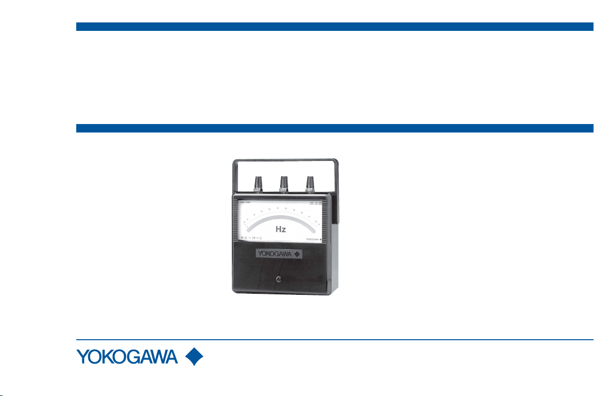
Portable Frequency Meter
IM 2038-01
2018. 3 5 版
5th Edition: March 2018
Page 2

IM 2038-01
本器を安全にご使用いただくために
SAFETY PRECAUTIONS
本器を安全にご使用いただくために,ご使用に先だって以下
に記載された警告文,および取扱説明書<本文>を必ずお読
みいただき,注意,使用方法についての内容は必ず守ってく
ださい。
これらの注意 に反したご使用により生じた障害については,
YOKOGAWA は責任と保証を負いかねます。
このマニュアルは製品の一部として重要な内容を含んでいま
す。本器を廃棄するまで,本器を使用するときにすぐご覧に
なれるところに,このマニュアルを大切に保存してください。
The following general safety precautions must be observed
during all phases of operation, service and repair of this
instrument. Failure to comply with these precautions or with
specific WARNINGS given elsewhere in this manual violates
the safety standards of the design, manufacture and intended
use of the instrument.
YOKOGAWA assumes no liability for the customer’s failure to
comply with these requirements.
This manual is part of the product and contains important
information. Store this manual in a safe place close to the
instrument so that you can refer to it immediately.
Keep this manual until you dispose of the instrument.
— i —
Page 3
IM 2038-01
本器および取扱説明書には安全記号 が表示されています。
この安全記号は,人体および機器を保護するために,取扱注意
の警告,取扱説明書や添付資料を必ず読む必要があることを
警告しています。
警 告
感電の恐れがありますので,以下のことを必ず守って
ください。
・ 計器および付属機器を接続する場合は,回路が活線状態で
ないことを確認してから行ってください。
・ 接続端子は,緩みのないように確実に締め付けてください。
・ 通電中は,入力端子およびその他の端子またはプラグ挿入
口等に触れないでください。
・ 通電中は,ケースおよびカバーを開けないでください。
・ 定格電流,定格電圧(表示の上限)を超える入力を加えな
いように注意してください。
The safety symbol is shown both on the instrument and
throughout the instruction manual to draw attention to the necessary
safety precautions.
WARNING
To avoid injury or death to personnel and damage to the
instrument, be sure to comply with the following.
• Make sure that the source voltage is not alive before you
attempt to connect the instrument to the circuit.
• Once you have connected the instrument to the circuit, tighten
the terminals.
• Never touch the terminals or plug holes when operating the
instrument.
• Never open the case or cover when operating the instrument.
• Be sure not to exceed the rated current and the rated voltage
(the upper limit of indication).
— ii —
Page 4

IM 2038-01
目 次
CONTENTS
本器を安全にご使用いただくために ................................... i
概 要 .............................................................................................. 1
取扱法および使用上の注意 ..................................................... 2
結線と測定..................................................................................... 3
保 守 .............................................................................................. 4
仕 様 .............................................................................................. 5
保 証
本器は,厳密な社内検査を経て出荷されておりますが,万一
製造上の不備による故障あるいは輸送中の事故等による故障
の節は,お買上げいただいた販売店または当社販売員にお申
しつけください。
当社製品の保証期間はご納入日より 1 年間です。この間に発
生した故障で,原因が明らかに当社の責任と判定された場合
には無償修理いたします。
SAFETY PRECAUTIONS .................................................. i
INTRODUCTION ............................................................... 1
OPERATING INSTRUCTIONS ......................................... 2
CONNECTION and MEASUREMENT ............................. 3
MAINTENANCE ................................................................ 4
SPECIFICATIONS .............................................................. 5
Warranty
The 2038 instruments are shipped only after stringent inhouse inspection. Should the instrument suffer damage that
is attributable to improper manufacture or an accident during
transport, contact the sales representative from which you
purchased the product or your nearest YOKOGAWA sales
office
All products of YOKOGAWA are guaranteed for a period of one
(1) year from the date of delivery.
YOKOGAWA will repair the product in question, free of charge,
if the product fails during the guarantee period for reasons that
are evidently attributable to YOKOGAWA.
— iii —
Page 5

IM 2038-01
概 要
さげ手
指針
Pointer
計器カバー
Zero Adjust Screw
INTRODUCTION
携帯用指針形周波数計 2038
サと直流電流計を組合わせて周波数−電流変換を行い,周波数の直
読が可能な携帯用周波数計であります。指示計は振動,衝撃に強い
トートバンド指示方式を採用し,特性においても従来の周波数計に
比べて,すぐれた点を数多くもっています。
は,当社独自の微分形トランスデュー
The
2038 Portable Precision-pointer Frequency Meter
instrument that performs frequency-to-DC current conversion. It does this
by combining a differential transducer with a DC current meter in order to
read frequencies directly. Its indicator uses taut-band suspension, making
it more resistant to vibration and shock and, as a result, far superior to
conventional frequency meters.
Handle
測定端子
Terminal
目盛板
Dial
ミラー
Mirror
Cover
零位調整器
Fig.1
is a portable
— 1 —
Page 6

IM 2038-01
取扱法および使用上の注意
OPERATING INSTRUCTIONS
1. 計器は,直射日光の当たる場所,外部磁界のある場所,振動の
ある場所,あるいは高温高湿な環境では使用しないでください。
2. 計器は,常に水平位置(標準姿勢)で使用してください。
このとき最も正確な指示が得られます。
3. 多数の計器を並べて使用するときは,でき得る限り離して使う
ようにしてください。
4. 計器の結線に先だち測定範囲,極性等をよく確認し,端子の締
付けは確実に行ってください。
5. 測定に入る前に指針が目盛の零位に一致していることを確かめ
ます。もし一致していなければ零位調整器を左右に回して合わ
せます。ミラーに映った指針の像と指針とが一致する目の位置
で行ってください。ただし,指針の曲がりで零位から外れたも
のは,誤差の原因となりますので,零位調整器で合わせないよ
うにしてください。
6. 計器に,その最大目盛値以上の値をみだりに加えないよう注意
してください。測定値があらかじめ予測できない場合には最も
大きい測定範囲から順次下位に換えて測定してください。
7. 測定の精度を高めるために計器の指示はなるべく最大目盛値か
らその 1/2 の間の目盛で読みとれるような測定範囲の計器を選
びます。
8. 測定中に計器の窓ガラスの表面を乾いた布で強く拭きますと静
電気のため指示が変化することがありますので避けてください。
特に乾燥期にはご注意ください。
表面の汚れは,乾いた布で軽く拭きとってください。
1. Do not use the instrument in a location exposed to direct sunlight, an
external magnetic field or mechanical vibration or in a high-te perature
highly humid environment.
2. Place the instrument on a fairly level surface.
A horizontal position will give the highest accuracy.
3. When using a number of these instruments in an array, keep them as far
away from each other as possible.
4. Before wiring any of these instruments, carefully check the measuring
range and polarities. When wiring, securely fasten the terminals.
5. Before measurement, check that the pointer coincides exactly with the
zero scale point. If it does not turn the zero adjust screw provided on
the meter cover until the pointer meets the zero scale point.
Position your eye so that the mirror image of the pointer coincides with
the actual pointer. However, if the pointer is off from the zero scale
point because the pointer is bent, do not adjust using the zero adjust
screw because this will lead to errors.
6. Be careful not to apply an unreasonably large current or high voltage to
the instrument.
7. For the optimum instrument accuracy, select a measuring range such
that the indication may be read in the top half of the scale.
8. Try not to apply too much force when wiping the glass window surface
of the instrument during measurement. Doing so, may result in a
deviation in the indication due to static electricity.
This is especially true when the instrument is used in a dry season.
If the surface is dirty, clean it gently with a dry soft cloth.
— 2 —
Page 7

IM 2038-01
結線と測定
Fig. 2-1
電源
Power Source
負荷
Load
Fig. 2-2
電源
Power Source
負荷
Load
CONNECTION and MEASUREMENT
(1) あらかじめ電源電圧の概略値を把握し,定格電圧に合った測定
端子を選び結線します。
(2) 120 V 端 子は,50 〜 135 V の範 囲 で, ま た 240 V 端 子は,
130 〜 300 V の範囲で測定可能です。(スケール板に表示)
電源電圧が,300 V を超える場合は計器用変圧器を外付けして
使用します。
(3) 電源電圧を切ったときに,指針が一瞬マイナスに振り切れます
が,計器の異常ではありません。
10 〜 20 秒で指針は零位置に戻ります。
1. Measure the approximate voltage of the power source to be measured,
and then connect the power source to the measuring instrument.
2. The voltage input range of 120 V terminal is 50 to 135 V and the
voltage input range of 240 V terminal is 130 to 300 V.
(The input range is indicated on the scale plate.)
If it is higher than 300 V, connect a voltage transformer.
3. When the power source is cut off, the pointer deflects to the negative
side of the scale. This is not an abnormal phenomenon, but rather an
expected reaction of the instrument's operation.
The deflected pointer returns to the ero position in 10 to 20 seconds.
U
u
V
VT
v
— 3 —
Page 8

IM 2038-01
保 守
MAINTENANCE
1. 計器の保管は,直射日光の当たらない湿気の少ない場所にして
ください。また,埃りがかからないようにご留意ください。
2. 精度を確保し,常に正しい精度で測定するためにも定期的な校
正をおすすめします。
校正の周期は,計器の使用頻度や使用条件により異なりますが,
3 か月に 1 〜 2 回行えば理想的です。
アフターサービス
正常な動作を示さず修理を要する場合には,
当社または販売代理店へお申しつけください。
1. To ensure good measurement, keep the instrument free of dust,
moisture, and away from direct sunlight.
2. If an overload or excessive shock has caused the accuracy of the
instrument to become doubtful, check several scale points and compare
these readings with an instrument which has been properly calibrated.
If the accuracy of the instrument is found to differ from its rating,
recalibrate the instrument.
Ideally, the instrument should be calibrated once or twice every three
months, though this depends on how frequently the instrument is used
and the conditions under which it is operated.
NOTE
If any troubles occur in the instrument, contact your nearest
YOKOGAWA Sales office or sales agent.
— 4 —
Page 9

IM 2038-01
仕 様
SPECIFICATIONS
精度階級 : 次頁(次ページ)参照
定格電圧: 120/240 V
120 V: 50 〜 135 V で使用可能
240 V: 130 〜 300 V で使用可能
指針振れ角: 約 85°
目盛長: 約 135 mm
目盛区分: 次頁(次ページ)参照
絶縁試験: 電気回路と外箱間 DC 500 V にて 10 MΩ 以上
電圧試験: 電気回路と外箱間 2000 VAC, 5 秒間
使用温湿度範囲: 0 〜 40℃,30 〜 75% RH
保存温湿度範囲: − 10 〜+ 50℃,25 〜 80% RH
外形寸法: 約 195 × 170 × 87 mm
質量: 約 1.8 kg
アクセサリ(別売): 携帯用かばん 2291 01
Rated Accuracy: See the table on the next page
Rated Voltage:
120 V for models operated on a source voltage of 50 to 135 V
240 V for models operated on a source voltage of 130 to 300 V
Deflection Angle: Approx. 85°
Scale Length: Approx. 135 mm
Scale Division: See the table on the next page
Insulation Test: More than 10 MΩ at 500 VDC
between the circuit and case
Voltage Test: 2000 VAC, for 5 seconds
when measured between the circuit and case
Operating Temperature and Humidity Range:
0 to 40°C, 30 to 75% RH
Storage Temperature and Humidity Range:
-10 to 50°C, 25 to 80% RH
Dimensions: Approx. 195 × 170 × 87 mm
Weight: Approx. 1.8 kg
Optional Accessories: Carrying case model 2291 01
— 5 —
Page 10

IM 2038-01
<アクセサリ
計器用変圧器:0.2級
Voltage Transformer: 0.2%
* 受注停止製品
* Discontinued product
形名
Model
2038
コード
Code
31
32
2038 03 *
2038 04 *
2038 11 *
2038 12 *
精度階級 Accuracy: % of full scale value
Accessories>
形名
Model
2261
2261 02 *
2261 03 *
2262 00 *
コード
Code
01 110 V
測定範囲
Measuring Range
45 – 65 Hz
20 – 100 Hz
100 – 300 Hz
300 – 500 Hz
45 – 55 Hz
55 – 65 Hz
220/440/2200/3300 V
15/30/50/75 V
100/200/300/500 V
3300/6600 V
精度階級
Accuracy
一次
Primary
0.2
1.0
0.5
0.5
0.2
0.2
目盛区分
Scale Division
100区分(0.2 Hz/div)
100区分(1 Hz/div)
100区分(2 Hz/div)
100区分(2 Hz/div)
100区分(0.1 Hz/div)
100区分(0.1 Hz/div)
二次
Secondary
150 V
150 V
110 V
消費電力
Power Consumption
120 V Range: Approx. 1.3 VA
240 V Range: Approx. 2 VA
120 V Range: Approx. 1.3 VA
240 V Range: Approx. 2 VA
定格負担
Burden
15 VA
15 VA
15 VA
— 6 —
Page 11

Printed in China
 Loading...