

Page 1

User’s
Manual
YFGW410
Field Wireless
Management Station
IM 01W02D01-01EN
IM 01W02D01-01EN
2nd Edition
Page 2

Blank Page
Page 3

YFGW410 Field Wireless Management Station
IM 01W02D01-01EN 2nd Edition
CONTENTS
Introduction ..............................................................................................................i
Safety Precautions ..................................................................................................ii
Documentation Conventions ................................................................................iii
Information of User’s Manual Revision ...............................................................iv
Toc-1
Part A Outline of Field Wireless System Conguration
A1. Minimum System Conguration ...........................................................A1-1
A2. Minimum System Conguration with Redundant Field Wireless
Network ...................................................................................................A2-1
A3. YFGW410 in Redundant Conguration ...............................................A3-1
A4. YFGW410 in High-Level Redundancy Conguration .........................A4-1
IM 01W02D01-01EN
Page 4

Part B YFGW410 Product Description
B1. Introduction .............................................................................................B1-1
B2. YFGW410 Function Outline ...................................................................B2-1
B2.1 System Manager ............................................................................................ B2-1
B2.2 Security Manager ........................................................................................... B2-1
B2.3 Gateway .......................................................................................................... B2-1
B2.4 Wireless Network Conguration and Management Functions and
Others .............................................................................................................. B2-2
B3. Structure and Parts of YFGW410 ..........................................................B3-1
B3.1 Front View ....................................................................................................... B3-1
B3.2 Top View .......................................................................................................... B3-1
B3.3 Side and Rear Views ...................................................................................... B3-2
B3.4 RS-485 Conguration Switches ................................................................... B3-2
B3.5 Outline of Component Functions ................................................................. B3-3
B3.6 Reset Switch ................................................................................................... B3-3
B3.7 Shutdown Switch ........................................................................................... B3-3
Toc-2
B4. Checking the Product ............................................................................B4-1
IM 01W02D01-01EN
Page 5

Part C Installation
C1. Installation Environment .......................................................................C1-1
C2. Power Supply and Grounding ..............................................................C2-1
C2.1 Power Supply ................................................................................................. C2-1
C2.2 Grounding ....................................................................................................... C2-2
C3. Mounting .................................................................................................C3-1
C3.1 Mounting Direction ........................................................................................ C3-1
C3.2 Mounting to DIN Rails .................................................................................... C3-2
C3.3 Installation of the YFGW410 ......................................................................... C3-3
C4. Wiring .......................................................................................................C4-1
C4.1 Terminals and Communication Ports Connection ..................................... C4-1
C4.2 Power Supply Cable Connection ................................................................. C4-2
C4.3 Grounding ....................................................................................................... C4-6
C4.4 Communication Cable Connection .............................................................. C4-8
C5. Explosion-Proof Wiring .........................................................................C5-1
Toc-3
IM 01W02D01-01EN
Page 6

Part D System Construction
D1. Engineering Procedures........................................................................D1-1
D2. Tools to be Used for the Engineering ...................................................D2-1
D2.1 Overview of the Tools .................................................................................... D2-1
D2.2 Using the Field Wireless Management Console ........................................ D2-2
D2.2.1 System Requirements .................................................................... D2-3
D2.2.2 Launching the Tool .......................................................................... D2-3
D3. Constructing a Field Wireless System .................................................D3-1
D3.1 Setting Operation Items ............................................................................... D3-1
D3.2 Detail of Conguration ................................................................................. D3-2
D3.2.1 YFGW410 Settings ........................................................................ D3-2
D3.2.2 Operation Mode ........................................................................... D3-14
D3.2.3 Hopping Patterns ......................................................................... D3-14
D3.2.4 Field Wireless Networks .............................................................. D3-19
D3.2.5 Graphic Editor .............................................................................. D3-34
D3.2.6 Alert Settings ................................................................................ D3-46
D3.2.7 Sampling Data .............................................................................. D3-47
D3.2.8 Modbus Settings ........................................................................... D3-58
D3.2.9 Resource ...................................................................................... D3-65
D3.2.10 Downloading Wireless Network Settings ...................................... D3-66
D3.2.11 Other Setting Operations ............................................................. D3-69
Toc-4
D4. Starting up the Field Wireless System .................................................D4-1
D4.1 Procedure for System Start-up ..................................................................... D4-1
D4.2 Wireless Network Management ................................................................... D4-2
D4.2.1 Monitor Functions ........................................................................... D4-2
D4.2.2 The Monitor Start up Window ......................................................... D4-4
D4.2.3 Graphic Viewer ............................................................................... D4-6
D4.2.4 Topology Viewer ............................................................................ D4-21
D4.2.5 Backbone Device List ................................................................... D4-22
D4.2.6 Field Device List ............................................................................ D4-24
D4.2.7 Log Viewer .................................................................................... D4-26
D4.2.8 Functions Called from the Menu Bar ............................................ D4-29
IM 01W02D01-01EN
Page 7

Part E Operation and Maintenance
E1. Routine Maintenance .............................................................................E1-1
E1.1 Routine Maintenance ......................................................................................E1-1
E1.1.1 Operation Status of Wireless System ..............................................E1-1
E1.1.2 YFGW410 Maintenance ..................................................................E1-1
E1.2 Handling a Device in the Abnormal Status ..................................................E1-2
E1.3 Handling a Device in the Warning Status .....................................................E1-2
E2. Adding and Replacing a Device ............................................................E2-1
E2.1 Field Wireless Device .....................................................................................E2-1
E2.2 Field Wireless Access Point (YFGW510) ......................................................E2-2
E2.3 Field Wireless Management Station (YFGW410).........................................E2-2
E3. YFGW410 Maintenance in Hazardous Area .........................................E3-1
E4. Parts with Dened Life Spans ...............................................................E4-1
Toc-5
IM 01W02D01-01EN
Page 8

Part F Troubleshooting
F1. Field Wireless System ...........................................................................F1-1
F2. YFGW410 .................................................................................................F2-1
F2.1 Status Information ..........................................................................................F2-1
F2.2 Status Indicators and Actions .......................................................................F2-2
Toc-6
IM 01W02D01-01EN
Page 9

Part G Specications
G1. YFGW410 ................................................................................................ G1-1
G1.1 Standard Specication .................................................................................. G1-1
G1.2 Model and Sufx Codes ................................................................................ G1-3
G1.3 External Dimensions .....................................................................................G1-4
G2. Field Wireless Network ......................................................................... G2-1
G2.1 Field Wireless Network Specication .......................................................... G2-1
G2.2 Network Form (Topology) ............................................................................. G2-2
G2.2.1 Star Topology .................................................................................. G2-2
G2.2.2 Mesh Topology ................................................................................G2-2
G2.3 Precautions on Conguring a Wireless Network .......................................G2-3
G2.3.1 Route Specication ......................................................................... G2-3
G2.3.2 Redundancy of Wireless Route ...................................................... G2-3
G2.3.3 Support of Large-Scale Wireless System .......................................G2-3
G2.3.4 Hopping Pattern ..............................................................................G2-3
G2.3.5 Number of Hops .............................................................................. G2-4
G2.3.6 Communication between Devices .................................................. G2-4
G2.4 Duocast (ISA100.11a Standard) ....................................................................G2-4
G2.5 Standard Battery Life ..................................................................................... G2-5
G2.6 Restrictions .................................................................................................... G2-5
G2.6.1 Restrictions on Number of Connectable Devices by Network
Resources .......................................................................................G2-5
G2.6.2 Maximum Number of Host Systems ...............................................G2-6
G2.6.3 Duocast and Auto I/O Device .......................................................... G2-6
G2.7 Recommended Device List ........................................................................... G2-7
Toc-7
G3. Glossary of Terms and Abbreviations ................................................ G3-1
IM 01W02D01-01EN
Page 10

<Read Me First>
Introduction
This document describes the YFGW410 Field Wireless Management Station (hereafter simply
refered to as YFGW410), which is a core component of the eld wireless system that based on
ISA100.11a, the wireless communication standard for industrial automation specied by the
International Society of Automation (ISA).
Functions of the YFGW410 are explained in the outline of the eld wireless system, and in the
installation, conguration, startup and operations of the eld wireless network.
The operation of Field Wireless Management Console, which is built in to the YFGW410 and
used as a tool for setup and management of a eld wireless network through YFGW410, is also
explained in this document.
i
IM 01W02D01-01EN
Page 11

<Read Me First>
Safety Precautions
IMPORTANT
Be sure to read the safety precautions for this product described in “Read Me First (IM
01W02D01-11EN)”.
n Transportation of products containing lithium batteries:
This product contains lithium batteries. Primary lithium batteries are subject to transportation
regulations by the U.S. Department of Transportation, and are also covered by the International
Air Transport Association (IATA), the International Civil Aviation Organization (ICAO), and the European Ground Transportation of Dangerous Goods (ARD). It is the responsibility of the shipper
to ensure compliance with these or any other local requirements. Consult current regulations and
requirements regarding lithium batteries before shipping.
ii
n How to dispose of batteries:
The following is an explanation about the new EU Battery Directive (DIRECTIVE 2006/66/EC).
This directive is only valid in the EU.
Batteries are included in this product. Batteries in this product cannot be removed by yourself.
Dispose of them together with this product.
If you dispose of this product within the EU, contact your local Yokogawa Europe B.V. ofce.
Do not dispose of them as domestic household waste.
Battery type: lithium thionyl chloride primary battery
CAUTION
The symbol (see above) means they shall be sorted out and collected as ordained in ANNEX II in
DIRECTIVE 2006/66/EC.
IM 01W02D01-01EN
Page 12

<Read Me First>
Documentation Conventions
n Typographical Convention
The following typographical conventions are used throughout the manuals:
l Conventions commonly used throughout manuals
Character string to be entered
The characters to be entered are shown in one-byte characters as follows:
Example:
FIC100.SV=50.0
“” mark
Indicates a space between character strings to be entered.
Example:
AL PIC010 -SC
Character string enclosed in curly brackets ({ })
Indicates an optional characters that can be omitted.
Example:
iii
PR TAG {. Sheet name}
l Conventions used to show key or button operations:
Characters enclosed in square brackets ([ ])
Characters enclosed in square brackets show the names of buttons used during the explanation
of the software operation.
Example:
To execute the command, click [OK].
Characters enclosed in angle brackets (< >)
Characters enclosed in angle brackets show the title of the screen during the explanation of the
software operation.
Characters enclosed in corner brackets ([ ])
Characters enclosed in corner brackets show a tab or an item of the screen during the explanation of the software operation.
n Symbols used in the manual
The symbol used in the manual are described in “Read Me First” (IM 01W02D01-11EN).
n Drawing Conventions
Some drawings may be partially emphasized, simplied, or omitted, for the convenience of description.
Some screen images depicted in the manual may have different display positions or character
types (e.g., the upper/lower case). Also note that some of the images contained in this manual
are display examples.
IM 01W02D01-01EN
Page 13

<Read Me First>
Information of User’s Manual Revision
Material Name : YFGW410 Field Wireless Management Station
Material Number : IM 01W02D01-01EN
Edition Date Page Revised Item
1st August 2012 - New Issue
2nd February 2013 -
Part A
B3-2, C4-8
D3-15
D4-29, D4-31
G1-1, G1-3
G2-1, G2-2
G2-5
G2-6
G3-1
Revise descriptions about a number of connectable devices,
and typography.
Change a number of connectable devices.
Add description about RS-485.
Revised descriptions about HoppingPattern.
Add description about a radio prohibit function.
Change communication services and its capability.
Change a number of connectable devices, and add list of
communication services.
Add description about a number of connectable output devices.
Add description about a capablity for the host system.
Add Glossary
iv
IM 01W02D01-01EN
Page 14
<A1. Minimum System Conguration>
Part A Outline of Field Wireless System
Conguration
The YFGW410, the YFGW510 Field Wireless Access Point (hereafter simply refered to as
YFGW510), the YFGW610 Field Wireless Media Converter (hereafter simply refered to as
YFGW610) and eld wireless devices are used to build an industrial wireless network that based
on to ISA100.11a, the wireless communication standard for industrial automation specied by the
International Society of Automation (ISA).
This part describes the typical conguration of eld wireless system that can be established using
these devices.
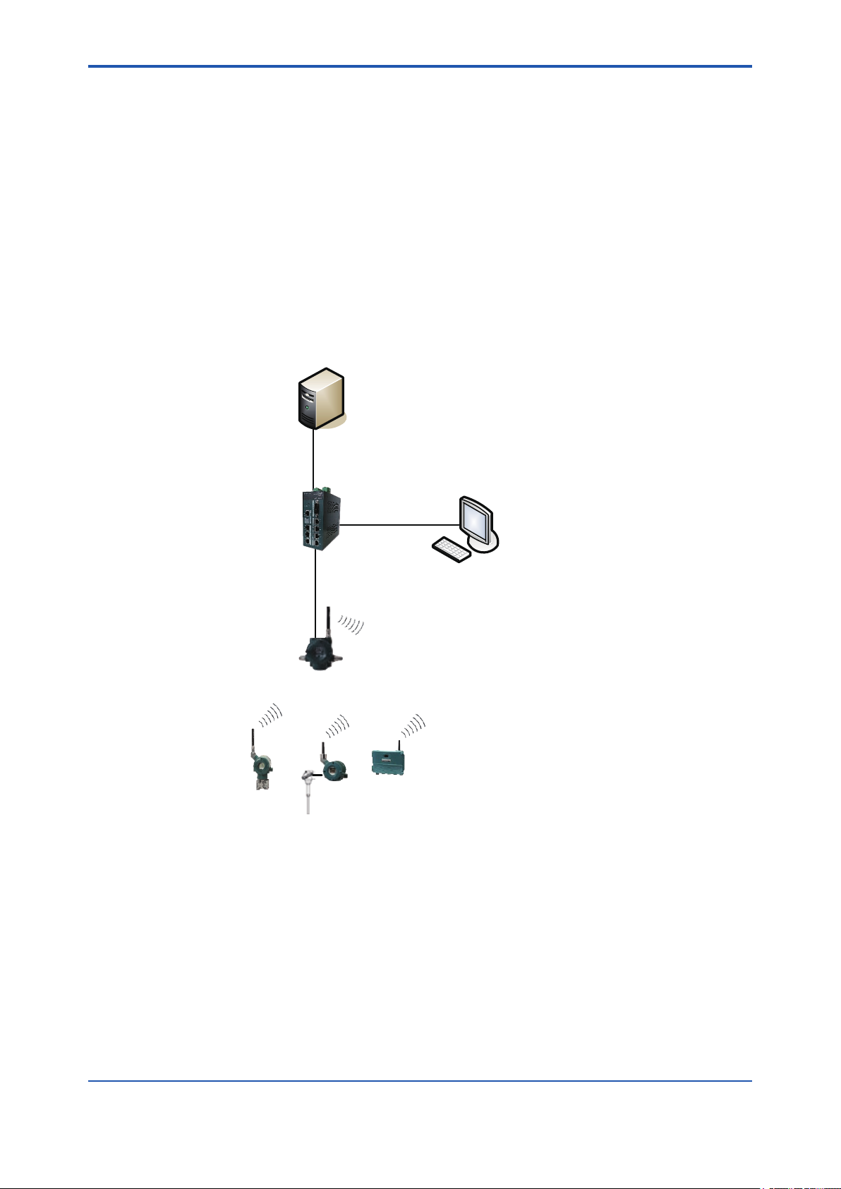
A1. Minimum System Conguration
Host system
A1-1
Field Wireless
Management Station
(YFGW410)
Field Wireless
Management Console
Field Wireless
Access Point
Field wireless network
(ISA100.11a)
Field wireless device
Figure A1-1 Minimum system conguration example (The eld wireless backbone using metal network)
(YFGW510)
FA0101.ai
This is the minimum conguration to monitor and record the process data of eld wireless devices.
This system consists of eld wireless devices, the YFGW510, YFGW410, and data monitoring
and recording devices (DAQSTATION, STARDOM and others) or the host system (DCS, SCADA
and others) supporting the Modbus/TCP communication.
The eld wireless subnet (the eld wireless network consisting of the YFGW510 and eld wireless devices) can be connected up to 100 eld wireless devices. In this conguration, up to 100
eld wireless devices can be connected.
IM 01W02D01-01EN
Page 15

<A1. Minimum System Conguration>
Up to 20 eld wireless subnets can be connected to the YFGW410.
Any of the three types of eld wireless backbone can be selected for between YFGW410 and
YFGW510.
• The metal network composed of the YFGW510 (100BASE-TX model), shown in Figure
A1-1
• The optical ber network shown in Figure A1-2, composed of the YFGW610 connected to
the YFGW410, uses the YFGW510 (100BASE-FX model) for signal transmission via optical
ber cables.
• The wireless LAN network shown in Figure A1-3, composed of other manufactures’ wireless
LAN access point (connected to the YFGW410) for wireless LAN communication with the
YFGW510 (wireless LAN client model).
The Field Wireless Management Console, which is the program built in to the YFGW410, is used
for conguration and management of a eld wireless network. This program can be started and
operated by the PC connected via the eld network interface or via the maintenance interface of
the YFGW410.
Certain parameters need to be set on the following devices to congure and start the wireless
network. For the relevant procedure, see the Provisioning and Conguration section.
• YFGW410 The device parameters, wireless network conguration, commu-
nication with host system, and others
A1-2
• YFGW510 The device parameters
Wireless LAN parameters if the wireless LAN client model is
selected
• Field wireless devices Provisioning and sensor parameters, and others
Once the eld wireless network has started, the eld wireless device parameters can be set and
those devices can be managed from the Plant Resource Manager (PRM) connected to the host
network. If the security policy for the host system is acceptable, the FieldMate can be used for
parameter setup and maintenance. The FieldMate is connected to the YFGW410 via the maintenance interface.
IMPORTANT
When CENTUM VP is running, set and adjust the parameters of the eld wireless device from
PRM.
When CENTUM VP is not running, or when a non-Yokogawa host system is connected, the parameters can be set and adjusted using FieldMate.
IM 01W02D01-01EN
Page 16
<A1. Minimum System Conguration>
Host system
Field Wireless
Management Station
(YFGW410)
Field Wireless
Management Console
Field Wireless
Media Converter
(YFGW610)
A1-3
Optical network
Field wireless network
(ISA100.11a)
Field wireless device
Field Wireless
Access Point
(YFGW510)
FA0102.ai
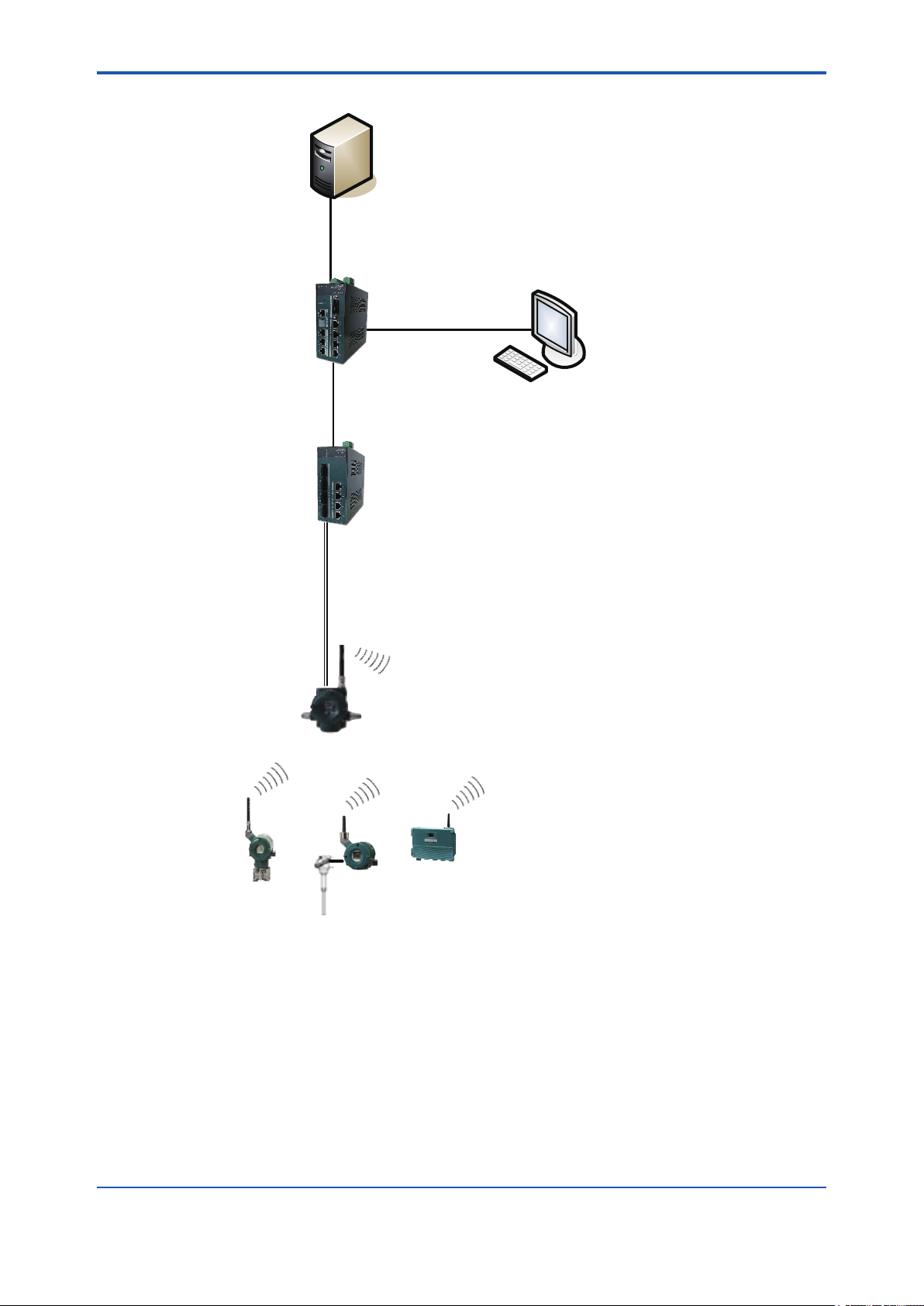
Figure A1-2 Minimum system conguration example (The eld wireless backbone using optical network)
In this conguration, YFGW610 and YFGW510 are connected through optical network cables.
The YFGW610 needs to be installed near YFGW410 for media conversion between optical
network and metal network.This is a useful method if the distance is too far from YFGW410 to
YFGW510. Also in order to eliminate the inuence of electromagnetic noise due to lightning and
keep transmission distance.
IM 01W02D01-01EN
Page 17

<A1. Minimum System Conguration>
Host system
Field Wireless
Management Station
(YFGW410)
Subnet A Subnet B
Wireless LAN access point
(other manufactures)
Wireless LAN access point
(other manufactures)
Wireless LANWireless LAN
Field Wireless
Management Console
A1-4
Field wireless
network
(ISA100.11a)
Field Wireless
Access Point
(YFGW510)
Field wireless
network
(ISA100.11a)
Field wireless deviceField wireless device
Field Wireless
Access Point
(YFGW510)
FA0103.ai
Figure A1-3 Minimum system conguration example (The eld wireless backbone using wireless LAN
network)
In this conguration example, the wireless LAN access point (other manufactures) is installed on
the eld wireless backbone, and each YFGW510 is connected to the eld wireless backbone via
the wireless LAN. If YFGW510 are connected via the wireless LAN, a single YFGW510 can be
connected to a single eld wireless subnet. Using YFGW510 wireless LAN redundancy model
and two wireless LAN access points, the wireless LAN communication can be made redundant.
Similar to the other eld wireless backbone network, up to 20 eld wireless subnets can be connected to the YFGW410. Up to 100 eld wireless devices can be connected in each eld wireless
subnet, and up to 500 eld wireless devices can be connected to the YFGW410.
For the recommended wireless LAN access points, see Section G2.7 Recommended Device
List.
IM 01W02D01-01EN
Page 18
<A2. Minimum system conguration with redundant eld wireless network>
A2-1
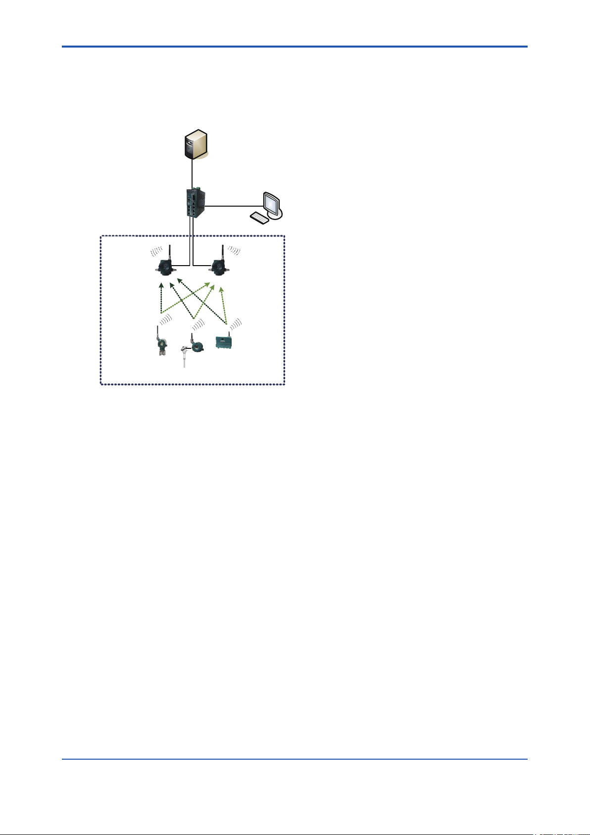
A2. Minimum System Conguration with
Redundant Field Wireless Network
Host system
Field Wireless
Management Station
(YFGW410)
Field Wireless
Management Console
Subnet A
Field Wireless
Access Point
(YFGW510)
Field wireless
network
(ISA100.11a)
Field wireless device
Field Wireless
Access Point
(YFGW510)
FA0201.ai
Figure A2-1 Minimum system conguration with redundant eld wireless network
This is redundant eld wireless network conguration. Two YFGW510 are installed in the eld
wireless network, and the eld wireless devices communicate with the both YFGW510 (Duocast). The communication path from the eld wireless devices to the YFGW410 is made redundant.
This system redundancy can prevent various types of interference in the eld wireless network
environment and can maintain the high quality connection.
Up to 100 eld wireless devices can be connected to a single eld wireless subnet.
IM 01W02D01-01EN
Page 19
<A3. YFGW410 in Redundant Conguration>
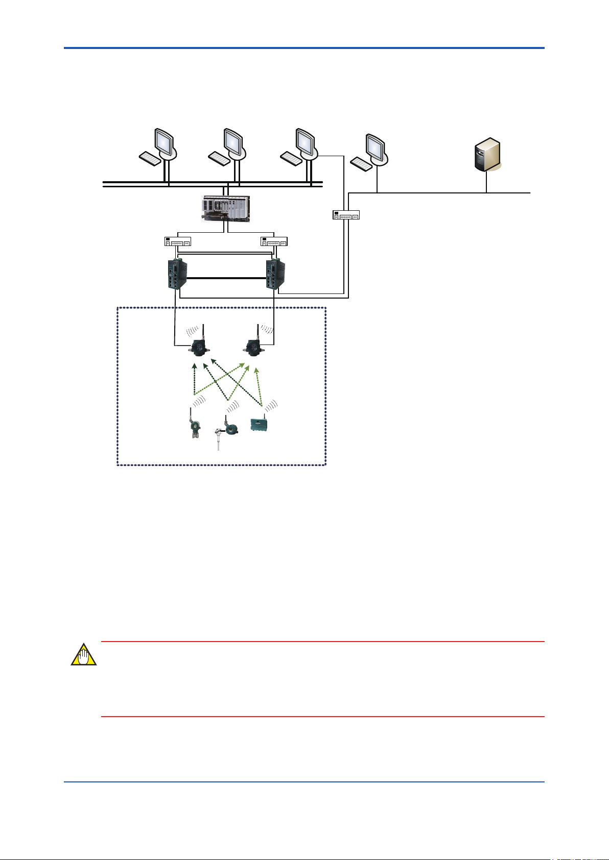
A3. YFGW410 in Redundant
Conguration
A3-1
HIS HIS/ENG PRM
Control network (Ethernet)
Subnet A
Field Wireless
Access Point
(YFGW510)
Field wireless
network
(ISA100.11a)
L2SWL2SW
Cable for Redundancy
FCS
ALE111×2
Field Wireless
Management Station
(YFGW410)
Field Wireless
Access Point
(YFGW510)
"Field wireless management PC
- Field Wireless Management Console"
L3SW
NTP server
Ethernet
Field wireless device
FA0301.ai
Figure A3-1 Redundant system conguration of YFGW410
In this example, the both of YFGW410 and YFGW510 are made redundant system. In using the
Duocast, the eld wireless devices are made fully redundant and a highly reliable system.
Two YFGW410 virtually operate as a single machine, and the backbone devices and host system
devices access to this virtual machine.
When one of YFGW410 is out of service by failure, another YFGW410 continue operation. One
failure does not affect a eld wireless system.
Up to 100 eld wireless devices can be connected to a single eld wireless subnet even in the
redundant conguration. Up to 500 eld wireless devices can be connected to YFGW410.
The host system is DCS, SCADA system, or the device management application.
IMPORTANT
When CENTUM VP is running, set and adjust the parameters of the eld wireless device from
PRM. When CENTUM VP is not running, or when a non-Yokogawa host system is connected,
the parameters can be set and adjusted using FieldMate.
IM 01W02D01-01EN
Page 20

<A3. YFGW410 in Redundant Conguration>
IMPORTANT
When CENTUM VP is used with YFGW410 in redundant conguration, CENTUM VP R5.02.00
or higher is required. For details, see the Communication with Subsystems Using FIO user’s
manual (IM 33K03L20-50E).
A3-2
IM 01W02D01-01EN
Page 21
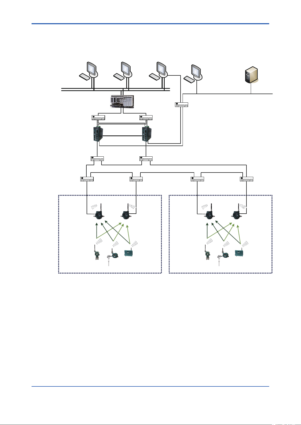
<A4. YFGW410 in High-Level Redundancy Conguration>
A4-1
A4. YFGW410 in High-Level Redundancy
Conguration
HIS HIS/ENG PRM
Control network (Ethernet)
FCS
ALE111×2
L2SW L2SW
Cable for Redundancy
L2SW (IEEE 1588) L2SW (IEEE 1588)
L2SW (IEEE 1588) L2SW (IEEE 1588) L2SW (IEEE 1588) L2SW (IEEE 1588)
Subnet A
Field Wireless
Access Point
(YFGW510)
Field Wireless
Access Point
Management Station
(YFGW510)
Field Wireless
(YFGW410)
Subnet B
Field Wireless
Access Point
(YFGW510)
"Field wireless management PC
- Field Wireless Management Console"
L3SW
NTP server
Ethernet
Field Wireless
Access Point
(YFGW510)
Field wireless network
(ISA100.11a)
Field wireless device
Field wireless network
(ISA100.11a)
Field wireless device
Figure A4-1 High-Level redundancy system conguration of YFGW410
In this conguration, the system consists of redundant YFGW410 and redundant Modbus/TCP
client of the host system. Yokogawa’s Modbus/TCP client can be made redundant using the FCS
(Field Control Station) of CENTUM VP. For details, see the CENTUM VP User’s Manual
(IM 33K03L20-50E for R5, or IM 33M01A30-40E for R4).
The YFGW410 in redundant conguration operates as a single virtual machine for the Modbus/
TCP clients. Although the YFGW410 has the L2SW functions, the eld wireless backbone network can be expanded by adding another L2SW between the eld wireless backbone devices.
The L2SW needs to be used which supports the IEEE 1588 v2 precision time protocol and the
RSTP or another loop detect functions. If a L2SW is used that is not supporting the IEEE 1588 v2
protocol and RSTP function, its operation is not guaranteed. Enable the IEEE 1588 v2 precision
time protocol of L2SW, and operate the switch in E2E 2-step TC mode. Also, enable the RSTP or
another loop detect function.
FA0401.ai
IM 01W02D01-01EN
Page 22

<A4. YFGW410 in High-Level Redundancy Conguration>
In the redundant YFGW410, need to connect the system to the YFGW510 using following method:
• Direct connection between YFGW410 and YFGW510 (shown in Figure A3-1)
• A single L2SW is installed for each backbone device. The L2SW have to connect as a loop.
(shown in Figure A4-1).
For the recommended L2SWs whose operations have been proven on the eld wireless backbone system, see Section G2.7 Recommended Device List. If a non-recommended L2SW is
used, its operation is not guaranteed even when the above functional requirements are satised.
IMPORTANT
When connecting the L2SW between YFGW410 and YFGW510, requirements for operation to
the backbone network are the following.
- Use IEEE1588 v2 compliant product to L2SW.
- Enable Rapid Spanning Tree Protocol (RSTP) or another loop detection function.
A4-2
IMPORTANT
When CENTUM VP is running, set and adjust the parameters of the eld wireless device from
PRM.
When CENTUM VP is not running, or when a non-Yokogawa host system is connected, the parameters can be set and adjusted using FieldMate.
IMPORTANT
When CENTUM VP is used with YFGW410 in redundant conguration, CENTUM VP R5.02.00
or higher is required. For details, see the Communication with Subsystems Using FIO user’s
manual (IM 33K03L20-50E).
IM 01W02D01-01EN
Page 23

<B1. Introduction>
Part B YFGW410 Product Description
B1. Introduction
This chapter outlines the functions and hardware conguration of the YFGW410.
YFGW410 is a core device in the eld wireless network, and it is used for conguration and management of a eld wireless network and for data transfer to the host system. A single YFGW410
is always required for the eld wireless network, and two YFGW410s are required for redundacy
system.
The YFGW410 can be mounted on the DIN rails, and it is usually mounted on the panel or wall in
the cabinet.
B1-1
IM 01W02D01-01EN
Page 24

<B2. YFGW410 Function Outline>
B2. YFGW410 Function Outline
The following outlines the YFGW410 functions.
YFGW410 has the System Manager, Security Manager, and Gateway functions. Also, this device
has the switching hub functions to connect the host system, PC to operate Field Wireless Management Console and other applications.
B2.1 System Manager
The System Manager controls the wireless communication of eld wireless devices, congures
the eld wireless backbone devices, and provides the database function.
The management function of the eld wireless device establishes a communication path to each
eld wireless device, monitors the Join or Leave status of each eld wireless device, and noties
the Field Wireless Management Console with an abnormality. Also, this function determines the
communication availability in conjunction with the Security Manager.
The management function of the eld wireless backbone device is used to initialize the IP address, network address and others of the YFGW410 and YFGW510.
The database function of the eld wireless network is used to manage the network information data contained in the YFGW410 and to control the data synchronization during redundant
YFGW410 system conguration.
B2-1
B2.2 Security Manager
The Security Manager has the functions for eld wireless device authentication and for encryption key management.
The Security Manager allows eld wireless devices to join to the network with the Join key, Session key and others. This manager is used to create, update, and delete an authentication/encryption key during communication.
B2.3 Gateway
The YFGW410 bridges between the eld wireless network and the host system.
During Modbus communication, the eld wireless device data is transmitted to the host system.
The Read Input Register, Read Holding Register, and Write Holding Register functions are supported. Before transmitting data to the host system, it is necessary to map the transmission process value, device status, alert information and other data to registers.
In the ISA100.11a protocol communication, the information about eld wireless network state and
device state of this network is transmitted when requested by the host system. Also, the gateway
relays a request and its response between the host system and eld wireless devices.
The Gateway can cache the diagnosis data acquired through communication with the eld wireless device in the YFGW410’s internal memory. The efcient communication to wireless eld
devices can use a wireless band exibly and improve the response to the host system.
IMPORTANT
When access to the Modbus registers that are not mapped in YFGW410, a non-zero data may
be contained.
IM 01W02D01-01EN
Page 25

<B2. YFGW410 Function Outline>
IMPORTANT
Writing to the Holding Register of Modbus by CENTUM VP requires R5.02.00 or higher. For details, see the Communication with Subsystems Using FIO user’s manual (IM 33K03L20-50E).
B2.4 Wireless Network Conguration and
Management Functions and Others
The YFGW410 has the software tools for conguration and management of eld wireless network on the Web page of this device. Connect to YFGW410 via Internet Explorer (IE) that are
installed on the eld wireless management PC.
B2-2
IM 01W02D01-01EN
Page 26
<B3. Structure and Parts of YFGW410>
B3. Structure and Parts of YFGW410
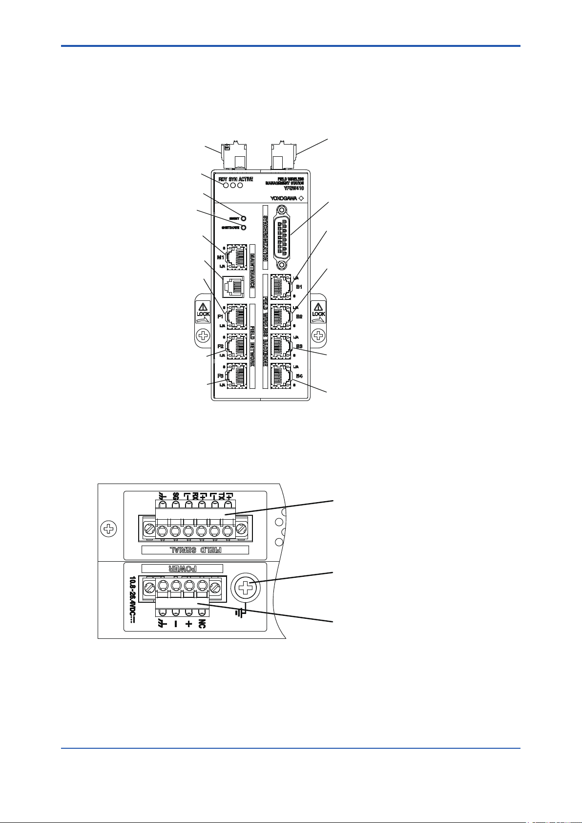
B3.1 Front View
B3-1
RS-485 connector
Status indicator LED
Reset switch
Shutdown switch
Maintenance interface
Serial port
Field network interface 1
Field network interface 2
Field network interface 3
Figure B3-1 YFGW410 front view
Power supply connector
Synchronization connector
Field wireless
backbone interface 1
Field wireless
backbone interface 2
Field wireless
backbone interface 3
Field wireless
backbone interface 4
FB0301.ai
B3.2 Top View
Figure B3-2 YFGW410 top view
RS-485 connector
Ground terminal
Power supply connector
FB0302.ai
IM 01W02D01-01EN
Page 27
<B3. Structure and Parts of YFGW410>
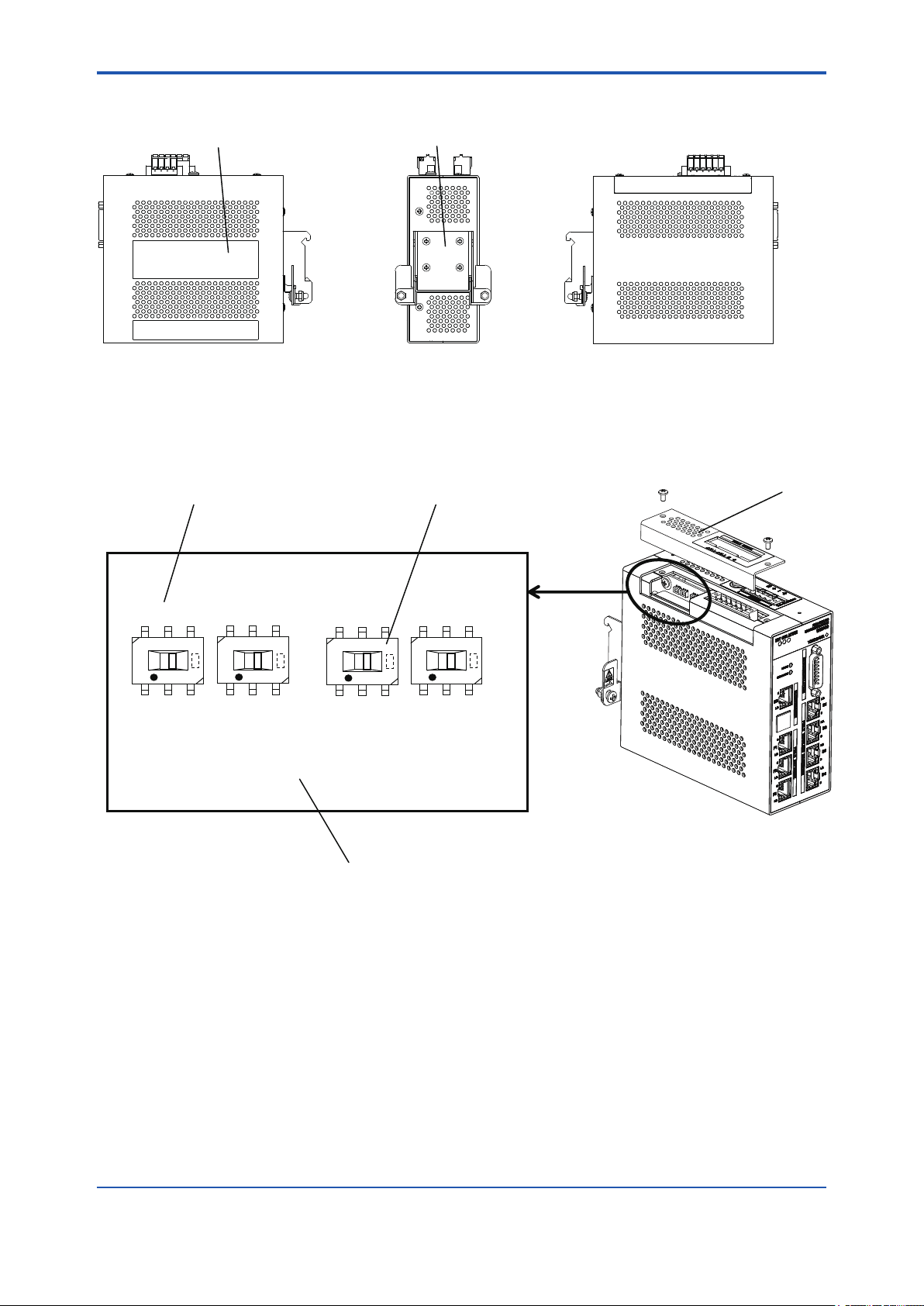
B3.3 Side and Rear Views
Name plate DIN rail mounting bracket
B3-2
Right side Rear
Figure B3-3 YFGW410 side and rear views
B3.4 RS-485 Conguration Switches
Switch number RS-485 configuration switches
SW602
SW604
SW603
SW605
Left side
FB0303.ai
Top cover
Circuit board
Figure B3-4 RS-485 Conguration Switches
FB0304.ai
IM 01W02D01-01EN
Page 28

<B3. Structure and Parts of YFGW410>
B3.5 Outline of Component Functions
Table B3-1 Outline of the YFGW410 component functions
Name Function Reference
RS-485 connector Connects to the host system that uses Modbus/RTU communi-
RS-485 conguration
switches
Status indicator LED A combination of three RDY, SYN, and ACTIVE LEDs indicates
Reset switch Resets the YFGW410. B3.6
Shutdown switch Shuts down the YFGW410. B3.7
Maintenance interface Connects the Field Wireless Management Console for setup and
Serial port Used for YFGW410 maintenance only. (Do not use this port dur-
Field network interface 1 to 3 Connects to the host system that uses the Modbus/TCP, ISA100.
Power supply connector Supplies electric power to the YFGW410. C4.2
Synchronization connector Connects two YFGW410 devices to each other for synchronous
Field wireless backbone
interface 1 to 4
DIN rail mounting bracket Secures the YFGW410 onto DIN rails using brackets. C3.3
cation.
Congures connection type to the host system (4-wire / 2-wire) C4.4
the YFGW410 operation status.
maintenance of a eld wireless network.
The PC, that has the FieldMate for setup and management of
eld wireless devices via wireless network, can also be connected (if used for the system without CENTUM VP).
ing normal network conguration and operation.)
11a or other protocol communication.
communication in the redundancy conguration. Plug the terminating connector into it if the system is not redundant.
Connects YFGW510, YFGW610, and the wireless LAN access
point to congure the eld wireless backbone.
B3-3
C4.4
F2.2
C4.4
C4.1
C4.4
C4.4
C4.4
B3.6 Reset Switch
Resets YFGW410. Hold the Reset switch for more than six seconds, the database in the
YFGW410 is initialized. If the database is initialized, the entire setup information of the device is
cleared. Always make a backup copy of the database before starting its initialization.
IMPORTANT
When initializing the database, don’t power off until RDY LED becomes green. Otherwise initialization will be failed and YFGW410 may not work correctly.
B3.7 Shutdown Switch
Shuts down YFGW410. Hold the Shutdown switch more than six seconds. Once shut down the
YFGW410, start it again by turning the power supply OFF rst, and then turn it ON again.
IM 01W02D01-01EN
Page 29
<B4. Checking the Delivered Products>
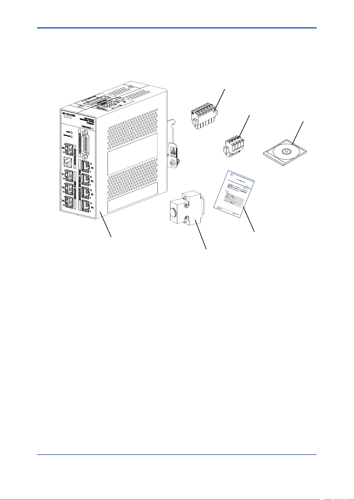
B4. Checking the Product
When you receive the product, please check the contents.
Check that the product specications match your order, that all parts are included, and that there
is no damage, stains, or other problems.
RS-485 connector
Power supply connector
B4-1
DVD-ROM
YFGW410
Read Me First
Terminator or Cable for Redundancy
Figure B4-1 Checkout of delivered products
● Read Me First (IM01W02D01-11EN Read Me First)
When specied manual language as an English.
● DVD-ROM (F9194TA)
When specied Software Media as DVD-ROM.
● Terminator or Cable for Redundancy
It depends on selection of Sync Connector Termination.
If With Terminator is specied, Terminator is included. Otherwise Cable for Redundancy is
included.
● Power supply connector and RS-485 connector
These are included as standard.
FB0401.ai
IM 01W02D01-01EN
Page 30

<C1. Installation Environment>
Part C Installation
This part describes the installation of the YFGW410.
Follow the steps below to use of the product.
1. YFGW410 installation
2. Power, ground, and signal cable connection
C1. Installation Environment
The system must be installed in an appropriate environment to ensure stable system operation.
The following denes the detailed specications of the YFGW410 installation environment.
Table C1-1 Installation environment specications
Item Specications Applicable
Ambient
temperature
Ambient
humidity
Temperature
gradient
Protection class IP20 IEC529
Vibration resistance 0.15 mm P-P (5 to 58 Hz)
Impact resistance 15 G, 11 ms (no conductive, and 3-direction half sine
Altitude Up to 3000 meters (due to restricted ambient tem-
Noise level Electric eld 3 V/m or less (80 MHz to 1 GHz)
Grounding Class D grounding
Cooling Natural cooling
Mounting Mounted on DIN rails.
Power
supply
Power consumption 10 W
Operating -40 to 65°C (at altitude below 2000 meters)
-40 to 55°C (at altitude between 2000 and 3000
meters)
Transport or storage
Operating 5 to 95% relative (without condensing)
Transport or stor-
age
Operating Within +/-10°C per hour JEIDA 29 Class B
Transport or stor-
age
Electrostatic
discharge
Voltage range 10.8 to 26.4 VDC
Rated voltage 24 VDC
Allowable ripple Less than 1% p-p
-40 to 85°C
5 to 95% relative (without condensing)
Within +/-20°C per hour
1 G (58 to 150 Hz)
waves)
perature)
4 kV or less (contact discharge), 8 kV or less (aerial
discharge)
IEC68-2-6
IEC68-2-27
C1-1
standards
CAUTION
When ambient temperature is beyond 50 °C, a temperature of the surface is very high. Please be
careful not to touch with bare hands.
IM 01W02D01-01EN
Page 31

<C1. Installation Environment>
IMPORTANT
• The temperature specication during operation indicates the criterion of the temperature
at the air intake of the bottom portion of modules. Do not block ventilation holes, as it may
hinder the air-cooling capabilities of the body. When installing YFGW410 in a cabinet, note
that the temperature specication is not in respect to the ambient temperature of the cabinet. Provide cooling fans in the cabinet if needed.
• Avoid exposing YFGW410 to direct sunlight.
• Prevent condensation under any circumstance.
• The dust level of the room should not exceed 0.3 mg/m
3
. Under any circumstance, avoid
iron akes, carbon particles, or any other type of dust that are conductive.
• Avoid existence of corrosive gases such as hydrogen sulde, sulfurous acid gas, chlorine,
and ammonia.
• YFGW410 should not share a ground wire with other devices.
n YFGW410 Vibration Criteria
C1-2
Ensure that if the frequency of vibration at the installation location is 58 Hz or less, the total amplitude is maintained less than 0.15 mm. If the vibration frequency is greater than 58 Hz, nd a
location that will meet the following condition:
Acceleration (m/s
2
) = 2π2 x A x F2 x 10-3 < 9.8 (=1 G)
A: Total amplitude (mm)
F: Frequency (Hz)
The range of allowable total amplitudes is shown below.
mm
0.2
0.15
0.1
Allowable range
0.05
Total amplitude
0
10 30 50 70 90 110 130 150Hz
Vibration frequency
FC0101.ai
Figure C1-1 Allowable Vibration Range
IM 01W02D01-01EN
Page 32

<C1. Installation Environment>
n Radio Device Noise to YFGW410
The following shows general requirements when using a radio device such as transceivers;
however, as a general rule, close the cabinet door when using a radio device:
• Transceivers that have 3 W of output power or less should be at least 1 m away. Transceivers that have 10 W of output power or less should be at least 2 m away.
• Radio devices that have 1 W of output power or less including cellular phones and cordless
phones should be at least 1 m away.
• The eld wireless device radio output is about 10 mW. There is no impact for YFGW410,
but keep to 1m than the same way as the 1 W output radio device.
C1-3
IM 01W02D01-01EN
Page 33

<C2. Power Supply and Grounding>
C2. Power Supply and Grounding
An appropriate power supply is necessary for the stable operation of YFGW410.
C2.1 Power Supply
Connect the power source to the spring terminal block located on the top of YFGW410.
SEE
For power supply and current consumption of the YFGW410, also see GS 01W02D01-01EN
ALSO
n Inrush current
When starting up, inrush current may run into the device. As shown in the table below, this current is, even though short-lived, signicantly larger (10 times or more) than the steady state current. Make sure that the power supply and protector can endure the inrush current.
Table C2-1 Inrush current specications
Item Specications Remarks
Inrush current 30 A, 2 ms or less At 26.4 VDC
C2-1
SEE
For wiring of the YFGW410 power supply, see Section C4.2 Power Supply Cable Connection.
ALSO
WARNING
• Conguration data may be corrupted if a power failure occurs during download to
YFGW410, YFGW510 and eld wireless devices. Conguration data is not corrupted even if
a power failure occurs at the time of the usual operation.
• When power failure is detected, the system may take a certain amount of time to recover to
the normal operation status.
• Please supply the power from the permanent power supply to avoid.
IMPORTANT
- YFGW410 does not have a power switch. Provide a breaker or switch for the external power
line to turn ON/OFF the device.
- The overcurrent protection circuit of the power supply, it is recommended to use the automatic-recover type with the reverse L-shaped.
IM 01W02D01-01EN
Page 34

<C2. Power Supply and Grounding>
C2.2 Grounding
Appropriate grounding is necessary for the stable operation of YFGW410. Class D grounding
(the third class grounding) with the ground resistance of 100 ohms or less is necessary. To connect the ground cable to YFGW410 directly, use the frame ground (FG) terminal on the top side
of the mainbody.
SEE
For grounding of the YFGW410, see Section C4.3 Grounding.
ALSO
C2-2
IM 01W02D01-01EN
Page 35

<C3. Mounting>
C3. Mounting
YFGW410 can be mounted on the DIN rails, and it is usually mounted on the panel or wall in the
cabinet.
No other type of mounting is allowed.
C3.1 Mounting Direction
YFGW410 is designed to be cooled by natural air. Install an YFGW410 so that the ventilation air
ows upward from its bottom to top as shown below. Mount in the correct direction.
Up
Air flow
C3-1
Air flow
Down
Figure C3-1 YFGW410 mounting direction
FC0301.ai
IMPORTANT
• Be sure to turn off the power before installing or removing YFGW410.
• Do not install the body blocking the ventilation holes on the top and bottom.
• At the top side, to prevent the cooling air current from being blocked, be sure to place the
body at least 150 mm away from other devices. This space is also used as a work area for
the power supply cable connection.
• At the bottom side, to prevent the cooling air current from being blocked, be sure to place
the body at least 100 mm away from other devices.
• At the side panel, to prevent the cooling air current from being blocked, be sure to place the
body at least 50 mm away from other devices. This space is also used as a work area for
the power supply cable connection.
• Do not expose to direct sunlight.
IM 01W02D01-01EN
Page 36

<C3. Mounting>
C3.2 Mounting to DIN Rails
First, install the DIN rails on the panel or the cabinet wall. Secure the DIN rails by tightening the
appropriate number of screws. Be careful that the rails do not get bent or deformed due to the
weight of the YFGW410 or cable tension.
To securely ground YFGW410, insert an insulation bushing between the DIN rails and mounting
panel and tighten the screws. Insulate the DIN rails from the metal surface of the mounting panel.
Insulation bushing
DIN rail
Insulation bushing
FC0302.ai
Figure C3-2 Use of insulation bushing
C3-2
IM 01W02D01-01EN
Page 37

<C3. Mounting>
C3.3 Installation of the YFGW410
1. Loosen the screws at both sides of the DIN rail mounting bracket (located on the rear panel
of the YFGW410), by rotating these screws in the reverse direction from the “Lock” position.
The screws do not drop even when fully loosened.
2. As shown in Figure C3-3, hook the top edge of the DIN rail mounting bracket onto the top of
the DIN rail, and return the YFGW410 back to the horizontal position. Then, hook the bottom
edge of the mounting bracket onto the bottom of the DIN rail.
3. Tighten the screws at both ends of the DIN rail mounting bracket, by rotating them toward
the “Lock” position. Tighten screws securely to ensure there is no clearance between the
bracket and the DIN rails.
4. Remove the YFGW410 by following the procedure described above in reverse.
After you have tightened the screws, loosen them by three turns.
C3-3
Figure C3-3 Mounting of the YFGW410 on DIN rails
FC0303.ai
IM 01W02D01-01EN
Page 38

<C3. Mounting>
FC0304.ai
Figure C3-4 Mounting example
C3-4
Figure C3-5 Mounting example (in redundant conguration)
FC0305.ai
IM 01W02D01-01EN
Page 39

<C4. Wiring>
C4. Wiring
This chapter explains the power, grounding, and communication cable connection to the
YFGW410.
C4.1 Terminals and Communication Ports
Connection
The YFGW410 has spring terminals to connect the power supply cable and serial communication
cables. Use the screw to connect the ground terminal with a ring-type crimp to the frame ground.
Use the RJ-45 connectors for Ethernet, and connect the metal network cables to the eld wireless backbone device interface, eld network interface, and maintenance interface.
Plug the cable for redundancy or the terminator to the synchonization connector.
The customer does not need to connect any cable to the serial port.
C4-1
RS-485 connector
Maintenance interface
Field network interface
Power supply connector
Synchronization connector
Field wireless
backbone interface
Figure C4-1 Terminals and Communication Ports View
FC0401.ai
IM 01W02D01-01EN
Page 40

<C4. Wiring>
C4.2 Power Supply Cable Connection
The YFGW410 has a 4-pin power supply connector (with a spring terminal; Phoenix Contact’s
FKC 2.5/4-STF) and the socket on the mainbody. The spring terminal base is secured by two
screws at both ends. To separate the terminal from the socket, loosening these screws.
There is enough space for cabling at the top and side panels of the YFGW410, leave the spring
terminals on the mainbody (as shown in Figure C4-2) and connect the positive and negative
power lines as indicated.
If there is insufcient space, separate the spring terminals from the socket, route the cables, and
secure the mainbody.
IMPORTANT
Be careful to connect the power supply cable with correct polarity. Because the YFGW410 does
not have a power switch, add a power switch or a circuit breaker to the external power line.
C4-2
1
2
3
4
Figure C4-2 Power supply cable connection procedure
FC0402.ai
IM 01W02D01-01EN
Page 41

<C4. Wiring>
To disconnect the power supply cable from the spring terminal, push down the orange areas
around the cable inlet and pull out the power supply cable from the socket.
FC0403.ai
C4-3
Figure C4-3 Disconnecting the power supply cable
l Applicable cables
Insulated cables for industrial equipment such as;
• 600 V polyvinyl chloride insulated wires (IV); JIS C3307
• Polyvinyl chloride insulated wires for electrical apparatus (KIV); JIS C3316
• 600 V grade heat-resistant polyvinyl chloride insulated wires (HIV); JIS C3317
• Heatproof vinyl insulated wires VW-1 (UL1015/UL1007)
• Control cables (vinyl insulated vinyl sheath cable) (CVV); JIS C3401
l Wire Size
Without sleeve: 0.2 mm2 to 2.5 mm2 (AWG24 to 14)
With sleeve: 0.2 mm
2
to 2.5 mm2 (AWG24 to 14)
IM 01W02D01-01EN
Page 42

<C4. Wiring>
l Wiring to spring terminals:1 (without sleeve)
- When using a solid conductor, strip the insulated cover and connect it.
Cable
Strip the solid conductor by 10 mm.
- When using a stranded conductor, strip the
insulated cover and twist and connect it.
Core
Length of exposed wire
Strip the stranded conductor for 10 mm.
Never solder the stranded conductor when connecting cables.
Be careful not to cause the loosely stranded conductor to come in contact with adjacent
terminals or others. Insert the cable leads into the terminal block securely.
l Wiring to spring terminals:2 (with sleeve)
The sleeve can prevent cable leads from untwist when you connect the cable. Select a sleeve to
match the cable size. If the length of cable leads does not match the length of sleeve (I
cable to the correct length. Strip the cable for a length so that the core wire slightly extends from
the metal tube of the sleeve. If this causes the length of the metal tube of the sleeve to be slightly
shorter than the stripping length, this is no problem.
C4-4
FC0404.ai
), strip the
2
The wiring cables and applicable sleeves are listed in the table below.
Use the same manufacturer for sleeves and tools.
Example of tool: Phoenix Contact’s CRIMPFOX 6
For details on sleeves and crimp tools, contact to Phoenix Contact Inc.
l
1
l
2
1
d
1
s
2
s
1
d
FC0405.ai
IM 01W02D01-01EN
Page 43

<C4. Wiring>
Table C4-1 List of power cables
Cable Dimensions (mm)
Section
area
2
(mm
)
AWG
Strip
length
(mm)
I
1
I
2
d
1
S
1
d
2
S
2
0.25 24 10 10.5 6.0 0.8 0.15 2.0 0.25 AI 0.25-6 BU
0.34 22 10 10.5 6.0 0.8 0.15 2.0 0.25 AI 0.34-6 TQ
10 12.5 8.0 0.8 0.15 2.0 0.25 AI 0.34-8 TQ
0.5 20 10 12.0 6.0 1.1 0.15 2.5 0.25 AI 0.5-6 WH
10 14.0 8.0 1.1 0.15 2.5 0.25 AI 0.5-8 WH
10 16.0 10.0 1.1 0.15 2.5 0.25 AI 0.5-10 WH
0.75 20 10 12.0 6.0 1.3 0.15 2.8 0.25 AI 0.75-6 GY
10 14.0 8.0 1.3 0.15 2.8 0.25 AI 0.75-8 GY
10 16.0 10.0 1.3 0.15 2.8 0.25 AI 0.75-10 GY
1.0 18 10 12.0 6.0 1.5 0.15 3.0 0.3 AI 1-6 RD
10 14.0 8.0 1.5 0.15 3.0 0.3 AI 1-8 RD
10 16.0 10.0 1.5 0.15 3.0 0.3 AI 1-10 RD
1.5 16 10 12.0 6.0 1.8 0.15 3.4 0.3 AI 1.5-6 BK
10 14.0 8.0 1.8 0.15 3.4 0.3 AI 1.5-8 BK
10 18.0 10.0 1.8 0.15 3.4 0.3 AI 1.5-10 BK
2.5 14 10 14.0 8.0 2.3 0.15 4.2 0.3 AI 2.5-8 BU
10 16.0 10.0 2.3 0.15 4.2 0.3 AI 2.5-10 BU
C4-5
Phoenix
Contact's type
IMPORTANT
• Use the same manufacturer for sleeves and tools.
• Use sleeve tools that match the wire thickness.
• Insert the wire to be connected completely into the pressure clamp terminal and attach it
securely.
• Secure the cable to cable clamps, etc. so that the weight of the cable applied to the terminal
is minimized.
• Strip the cable for a length so that the core wire slightly extends from the metal tube of the
sleeve. If this causes the length of the metal tube of the sleeve to be slightly shorter than the
stripping length, this is no problem.
IM 01W02D01-01EN
Page 44

<C4. Wiring>
C4.3 Grounding
Appropriate grounding is necessary for the stable operation of YFGW410. The YFGW410 has
two ground terminals: the frame ground (FG) terminal secured by the M4 screw at the side of
power supply connector (on the top side of the mainbody), and the ground terminal at the power
supply spring terminal.
Connect the ground cable from the frame ground (FG) terminal to the ground. Connect the cable
shield or others to the power supply spring terminal.The internal wiring of YFGW410 mainbody is
connected as shown in the following gure.
C4-6
Ground
terminal
Power supply
+
NC
connector
YFGW410 Housing
SG
RX RX +
TX TX +
RS-485
connector
FC0406.ai
Figure C4-4 Internal connection of the ground terminal
To ensure stable grounding, insulate the panel or DIN rails with YFGW410 from the metal surface
of external cabinet, rack and others by using insulation bushings or others. Then, connect the cable from YFGW410 to the ground. Class D grounding (the third class grounding) with the ground
resistance of 100 ohms or less is necessary. To connect the ground cable to YFGW410 directly,
use the frame ground (FG) terminal on the top side of the mainbody. YFGW410 should not share
a ground wire with other devices.
IM 01W02D01-01EN
Page 45

<C4. Wiring>
C4-7
Figure C4-5 Ground terminal connection procedure
FC0407.ai
IM 01W02D01-01EN
Page 46

<C4. Wiring>
l Applicable cables
Insulated cables for industrial equipment such as;
• 600V polyvinyl chloride insulated wires (IV); JIS C3307
• Polyvinyl chloride insulated wires for electrical apparatus (KIV); JIS C3316
• 600V grade heat-resistant polyvinyl chloride insulated wires (HIV); JIS C3317
• Heatproof vinyl insulated wires VW-1 (UL1015/UL1007)
l Wire Size
Core: AWG14 to 13 (2 mm2 to 2.6 mm2)
l Termination
Use a ring tongue terminal for M4 terminals: with an insulation sleeve
C4.4 Communication Cable Connection
C4-8
n Field wireless backbone device
Connect the 100BASE-TX compliance cable, terminated with an RJ-45 connector, to the eld
wireless backbone device interface on the front panel of the YFGW410.
Figure C4-6 Connection to eld wireless backbone
n Field network
Connect the 100BASE-TX compliance cable, terminated with an RJ-45 connector, to the eld
network interface on the front panel of the YFGW410.
Generally, connect the host system which transmits data using the ISA100.11a protocol to the F1
port of YFGW410. Connect the host system which transmits data using the Modbus/TCP protocol to the F2 or F3 port.
FC0408.ai
n RS-485
YFGW410 supports to communicate with the host system, which supports Modbus/RTU communication, via the RS-485 connector on top of the main body. 4-wire and 2-wire types are provided
for connection with the host system. Selecting connection type is set by RS-485 conguration
switches. YFGW410 supports only 1 to 1 connection.
RS-485 connector is a 6-pin connector with a spring terminal (Phoenix Contact FKC 2.5/6-STF).
For details of wiring, see C4.2 Power Supply Cable Connection. Regarding RS-485 communi-
IM 01W02D01-01EN
Page 47

<C4. Wiring>
cation cables, use shielded twisted pair cables (cables for RS-422/RS-485 communication are
recommended).
IMPORTANT
All RS-485 conguration switches are set to OFF by default. When connecting cables to the RS485 connector, set RS-485 conguration switches to t actual connection before power on.
l Connection in 4-wrie Type
YFGW410 Host System
TX+
TX-
TX+
R2
TX-
C4-9
RX+
R1
RX-
SG
FG
R1: Termination resistance of 120 Ω (comes with YFGW410)
R2: According to the instruction on the external equipment
Figure C4-7 Connection and Conguration in 4-wire Type
l Connection in 2-wire Type
YFGW410 Host System
TX+
TX-
RX+
R1
RX-
R2
TX+
TX-
RX+
RX-
R2
RX+
RX-
SG
FG
RS-485 Configuration Switches
SW602 SW603SW604 SW605
OFF OFF OFF ON
FC0409.ai
RS-485 Configuration Switches
SW602 SW603SW604 SW605
SG
FG
R1: Termination resistance of 120 Ω (comes with YFGW410)
R2: According to the instruction on the external equipment
Figure C4-8 Connection and Conguration in 2-wire Type
l Modbus/RTU
Following table shows Modbus/RTU communication parameter of YFGW410. The host system
should be congured in accordance with following parameters.
.
SG
FG
ON OFF ON ON
FC0410.ai
IM 01W02D01-01EN
Page 48

<C4. Wiring>
Table C4-2 Modbus/RTU Communication Parameters of YFGW410
Item Description Note
Serial Communication Boat rate: 38.4kbps
Parity: Even
Stop bit: 1 bit
Modbus/RTU Modbus Slave
Modbus/RTU Address: 1
Fixed values
Congure the host system as Modbus Master.
Modbus/RTU address of the host
system should be except 1.
IMPORTANT
Modbus/RTU supports to access up to 125 words at once. However, part of information may not
be accessed through Modbus/RTU, because number of accessible words depended on a Modbus/RTU client. For details, see users’ manual of the host system.
n Maintenance interface
C4-10
Connect the 100BASE-TX compliance cable, terminated with an RJ-45 connector, to the maintenance interface (M1) on the front panel of the YFGW410. Connect the Field Wireless Management Console to this port for conguration of a eld wireless network and the YFGW410.
IMPORTANT
When CENTUM VP is running, set and adjust the parameters of the eld wireless device from
PRM.
When CENTUM VP is not running, or when a non-Yokogawa host system is connected, the parameters can be set and adjusted using FieldMate.
n Synchronization connector
In order to build redundancy YFGW410, connect an attached cable for redundancy to the synchronization connector in the front of YFGW410. When using single YFGW410, connect the
terminator to the synchronization connector. If nothing has connected with a synchronization connector, YFGW410 does not operate.
IMPORTANT
• The cable for redundancy has the D-sub 15-pin connector at both ends. Secure the cable
connector to the synchronization connector using screws. When cables other than an attached cable for redundancy are connected, these operation is not guaranteed.
• If nothing has connected with a synchronization connector, YFGW410 does not operate.
IM 01W02D01-01EN
Page 49

<C5. Explosion-Proof Wiring>
C5. Explosion-Proof Wiring
- Application pending -
(Left blank intentionally)
C5-1
IM 01W02D01-01EN
Page 50

<D1. Engineering Procedures>
Part D System Construction
This part describes the ow and work content of the engineering in order to construct a Field
Wireless System.
D1. Engineering Procedures
Shippment
D1-1
Engineering of host system
System
(CENTUM VP, FAST/TOOLS,
engineer
DAQSTATION, and so on)
Backup file
Startup engineer or
wireless engineer
Modbus
registers file
Startup engineer or
wireless engineer
Startup engineer or
wireless engineer
Person in
charge of devices
Startup engineer or
wireless engineer
User or
startup engineer
Start-up
Engineering of field wireless network
(Configurator and YFGW410)
Configuration data
download to YFGW410
(Configurator)
Engineering of YFGW510
(Field wireless access point setup tool)
YFGW410
YFGW510
YFGW610
installation
Check and adjust wireless connection
Save the communication quality data
(Monitor)
Backup configuration data
(Configurator)
(Monitor)
Provisioning file
Field wireless device
(FieldMate)
Set device parameters
(FieldMate PRM)
Field wireless device installation
Set and adjust device parameters
(FieldMate PRM)
Loop check
Person in
charge of devices
Person in
charge of devices
Person in
charge of devices
Person in
charge of devices
User or
startup engineer
Operation
Operators
Device management
Maintenance staff
FD0101.ai
Figure D1-1 Engineering Flow for Wireless System Construction
The explanations in this document are based on the assumption that all engineering in the network construction is executed after the delivery of the components for the Field Wireless System
to the customer. When Yokogawa Electric Corporation receives an order that includes the engineering, the procedure may differ from the ow shown in Figure D1-1.
As shown in Figure D1-1, in order to construct a Field Wireless System that has been specically
designed according to a customer’s request, the following types of engineering are necessary:
(1) Provisioning and setting of the eld wireless device
(2) Construction of the Field Wireless System
(3) Engineering of the host system
IM 01W02D01-01EN
Page 51

<D1. Engineering Procedures>
n (1): Provisioning and Setting of the Field Wireless Device
Provisioning is conguration of the required information into a eld wireless device in order to
integrate it with the eld wireless network. This task is necessary in order to prevent third parties from making improper connections to the eld wireless network through methods such as
tampering or spoong. Devices on which provisioning has not been carried out or onto which the
incorrect information is congured cannot be integrated with the eld wireless network.
As shown in Figure D1-1, the following tasks are necessary before installing a eld wireless
device.
• Provisioning
Using FieldMate, the information that the eld wireless device requires in order to be integrated with the eld wireless network is congured via infrared data communication. This
task must be executed before the device is installed. Using the Provisioning Device tool on
FieldMate, provisioning is executed for the eld wireless device via infrared data communication.
• Setting and Adjustment of parameters
In the case of eld wireless devices manufactured by Yokogawa Electric Corporation, the
person in charge of devices can make settings and adjust the parameters via infrared data
communication before installing the device, by using FieldMate. This task can also be performed via a eld wireless network after the device is installed.
When performing these tasks before installing the device, use FieldMate R2.03.00 or later versions. For a eld wireless system, use applicable version of FieldMate and Device Files checked
by the website (http://www.eld-wireless.com/) For details, see Part I ISA100.11a Device Conguration in the FieldMate User’s Manual (IM 01R01A01-01E).
D1-2
n (2): Construction of the Field Wireless System
This task comprises the construction of a eld wireless network by the wireless system engineer
(including the start-up engineer) based on the detailed design information of the eld wireless
network by setting the YFGW410, the YFGW510 Field Wireless Access Point, and the eld wireless device.
The task includes constructing the network for the Field Wireless System, downloading information to the YFGW410, setting the YFGW510, verifying the startup and running status of the eld
wireless network, and, if necessary, correcting the network conguration, and setting and adjusting the parameters of the eld wireless device via the eld wireless network. The task of network
construction includes enabling or disabling redundancy in the YFGW410, registering and setting
the functions of the eld wireless device, setting up the communication paths, and dening process data in the Modbus registers.
For the detailed procedures, see Sub-section D3.2.8 “Setting Modbus” in this document.
The tasks of downloading information to the YFGW410 and verifying the startup and running status of the eld wireless network are assumed to be performed by the wireless system engineer
(including the start-up engineer) after the device has been delivered to the user’s plant site and
installed.
The task of setting and adjusting the device parameters is supposed to be performed by the
person in charge of the devices.
IM 01W02D01-01EN
Page 52

<D1. Engineering Procedures>
n (3): Engineering of the Host System
This task is the engineering of the host (control/monitoring) system by the system engineer.
The task targets system applications for which process data can be read/written using Modbus,
as well as applications for which the process values and parameters of the eld wireless device
can be read/written using the ISA100.11a protocol.
Some examples of target applications are shown below.
Modbus/TCP STARDOM, FA-M3R, DAQWORX, DAQSTATION, DAQMASTER,
CENTUM VP, FAST/TOOLS, other companies’ implementations of DCS/
SCADA
Modbus/RTU DAQMASTER and other companies’ implementations of DCS/SCADA
ISA100.11a PRM, FieldMate
OPC Applications that correspond to OPC servers (CENTUM VP, FAST/
TOOLS, etc.)
For details, see the User’s Manual for the relevant host system.
IMPORTANT
When CENTUM VP R4 is used, R4.02.30 or higher is required. For details, see Reference Subsystem Communication (Using FIO) (IM 33M01A30-40E).
D1-3
When CENTUM VP R5 is used, R5.02.00 or higher is required.
If CENTUM VP is used with YFGW410 in redundant conguration or writing output values to eld
wireless devices, CENTUM VP R5 is required. For details, see the Communication with Subsystem Using FIO user’s manual (IM 33K03L20-50E).
IM 01W02D01-01EN
Page 53

<D2. Tools to be Used for the Engineering>
D2-1
D2. Tools to be Used for the Engineering
In Figure D1-1 Engineering Flow for Wireless System Construction, the tools described in this
User’s Manual are shown in parentheses alongside the tasks.
This chapter describes the following tools included in Figure D1-1.
• Congurator
• Monitor
• Field wireless access point setup tool
• FieldMate
• PRM (Plant Resource Manager)
D2.1 Overview of the Tools
n Congurator
This tool is included in the Field Wireless Management Console that is built into the YFGW410. It
is used for constructing the eld wireless network.
It creates the conguration information for the wireless network conguration that is managed by
the YFGW410 based on the detailed design information of the wireless network. It also creates
conguration data based on the provisioning information of the eld wireless device, which contain information such as the devices to be integrated into the network, the roles of those devices,
the function settings for the data renewal cycles, etc., data allocations for the Modbus registers,
and other information.
These pieces of information are downloaded to the YFGW410 and the eld wireless device.
Congurator is launched from the Field Wireless Management Console on the YFGW410 via an
instance of Internet Explorer on a PC that is connected to maintenance interface or eld network
interface.
n Monitor
This tool is included with the Field Wireless Management Console that is built into the YFGW410.
It is used for monitoring the running status of Field Wireless System constructed .
Monitor displays the Packet Error Rate (PER), the Received Signal Strength Indicator (RSSI),
and the eld wireless network conguration gures for each wireless communication path, as
well as displaying information about the eld wireless device such as the battery life.
It is used for determining the communication stability when the Field Wireless System is started
and for monitoring daily status during operation.
Monitor is launched from the Field Wireless Management Console on the YFGW410 via an
instance of Internet Explorer on a PC that is connected to maintenance interface or eld network
interface.
IM 01W02D01-01EN
Page 54

<D2. Tools to be Used for the Engineering>
n Field wireless access point setup tool
The eld wireless access point setup tool makes the settings that YFGW510 requires in order to
be integrated with the eld wireless network (device tag and password).
This tool is a Windows PC application that is provided with YFGW510.
In the case of the wireless LAN option, it is also used to set parameters related to wireless LAN
(SSID, network key, etc.).
For details of operation, see the YFGW510 User’s Manual (IM01W02E01-01JA).
n FieldMate
This is a separately provided application for setting the parameters of the eld device.
In the Field Wireless System, the eld wireless device is provisioned and congured via infrared
data communication. Prepare the infrared adapter specied in the FieldMate User’s Manual (IM
01R01A01-01E).
If the host system for YFGW410 is not CENTUM VP manufactured by Yokogawa and there is
no PRM (mentioned later in this document), you can set the parameters by connecting a PC on
which FieldMate is installed to maintenance interface of YFGW410.
For details of operation, see the FieldMate User’s Manual (IM 01R01A01-01E).
D2-2
n PRM (Plant Resource Manager)
This is a separately provided application for monitoring the status of the eld device, and setting
and managing the parameters. It is used to create FDT projects on the FDT framework. Monitoring, conguration, and control are provided via a connection to the eld wireless device using
DTM.
The PC on which PRM is installed is connected to eld network interface of YFGW410.
For details of operation, see the Plant Resource Manager Reference (IM 33Y05Q10-11E).
D2.2 Using the Field Wireless Management
Console
The Field Wireless Management Console that is built into YFGW410 contains two tools: Congurator and Monitor.
The basic usage rights for the tool are as follows:
l Field Wireless Management Console: 1 license
l Congurator: 1 client
l Monitor: 3 clients
IM 01W02D01-01EN
Page 55

<D2. Tools to be Used for the Engineering>
D2.2.1 System Requirements
l PC environment
Item Recommended system requirements
CPU Intel Core 2 Duo 2.66 GHz or equivalent, or higher
RAM 2 GB or more
HDD 40 GB or larger (at least 15 GB of free space)
Communication interface Ethernet-compatible network ports
Display Color: True Color (24 bits or more) recommended
Resolution: 1280 x 800 recommended
D2-3
l PC software system requirements
OS Type
Windows 7 Professional Service Pack 1 32/64 bit
Windows Vista Business Edition Service Pack 2 32 bit
Windows Server 2008 Enterprise Service Pack 2 32 bit
Windows Server 2008 R2 Enterprise 32/64 bit
*1: Japanese or English versions are supported.
*2: Microsoft .NET Framework 3.5 Service Pack 1 must be installed.
*3: The 64 bit OS is compatible when using WOW64 (Windows 32-bit on Windows 64-bit).
*1*2*3
l Internet Explorer (IE) compatibility requirements
The tool works with the IE version bundled with each OS.
Target OS IE version
Windows 7 Professional SP1 (32/64 bit) IE 8.0
Windows Vista Business Edition SP2 (32 bit) IE 7.0
Windows Server 2008 Enterprise SP2 (32 bit) IE 7.0
Windows Server 2008 R2 Enterprise (32/64 bit) IE 8.0
D2.2.2 Launching the Tool
l Connecting and launching YFGW410
When YFGW410 is factory default, before power on, connecting the power, synchronization connector and eld network interface 1 is required. In addition, for a redundant conguration, two
YFGW410s should be connected each other with Cable for Redundancy.
The host system should be connected to eld network interface 1, and the PC which executes
the Field Wireless Management Console should be directly connected to maintenance interface.
If there is no host system, connect the PC which executes the Field Wireless Management Console to eld wireless interface 1.
For details, see Part A Outline of Field Wireless System Conguration and C4 Wiring.
IM 01W02D01-01EN
Page 56

<D2. Tools to be Used for the Engineering>
IMPORTANT
When launching YFGW410, if nothing is connected to eld network interface 1, or if the connected device is not running, YFGW410 may detect an error and may not launch properly.
IMPORTANT
The network should be congured that the PC which executes the Field Wireless Management
Console can access to YFGW410 through a eld network interface, during an operational state.
l PC settings
• When connecting the PC to the maintenance interface
The maintenance interface’s IP address at the time of shipment from the factory is
192.168.200.101. If the IP address of the PC is set as 192.168.200.xxx (xxx being a number
between 1 and 254, excluding between 101 and 106 and the addresses of other devices
connected to the same network segment), communication with YFGW410 becomes possible.
D2-4
• When connecting the PC to eld network interface 1
The IP address of the F1 port at the time of shipment from the factory is 192.168.0.101. If
the IP address of the PC is set as 192.168.0.xxx (xxx being a number between 1 and 254,
excluding between 101 and 103 and the addresses of other devices connected to the same
network segment), communication with YFGW410 becomes possible.
Because the Field Wireless Management Console is launched after it is downloaded to the PC
from YFGW410, there is no need to install it on the PC.
IMPORTANT
The Field Wireless Management Console cannot be launched via a proxy server. In Internet
Explorer, open the [Tools] menu, click [Internet Options], select the [Connections] tab, click [LAN
settings], and deselect the checkbox next to [Use a proxy server for your LAN].
l Launching the Field Wireless Management Console
After checking YFGW410 to conrm that the RDY LED, which shows the running status, is lit
green, launch Internet Explorer on the PC. To connect, enter the following URL in the address bar
on Internet Explorer.
http://(IP address of the communication port on YFGW410 to which the PC is connected):8080
http://192.168.0.101:8080
When the connection is successfully made, the window shown in Figure D2-1 is displayed.
IM 01W02D01-01EN
Page 57

<D2. Tools to be Used for the Engineering>
D2-5
FD0201.ai
Figure D2-1 Field Wireless Management Console launch window
This window has two buttons: [Congurator] and [Monitor].
• [Congurator] For constructing the eld wireless network
• [Monitor] For monitoring the running status of the eld wireless network
IMPORTANT
The Field Wireless Management Console becomes usable about one minute after the RDY LED,
which shows the running status of YFGW410, turns green. Depending on the status of the RDY
LED, access to the Field Wireless Management Console may not be possible. For the status of
the LED that shows the running status, see Section F2.2 Status Indicators and Actions.
l Logging in
When the [Congurator] or [Monitor] button is clicked, a window is displayed to indicate that the
application is running.
FD0202.ai
IM 01W02D01-01EN
Page 58

<D2. Tools to be Used for the Engineering>
IMPORTANT
It may be necessary to change the security settings of Internet Explorer. To change the security
level, follow the instructions on the window that is displayed.
The following security alerts may appear on the window. When this window is displayed, click the
[Run] button.
D2-6
FD0203.ai
When the application is successfully launched, the window shown in Figure D2-2 is displayed.
FD0204.ai
Figure D2-2 Login window
Item Description Maximum number of
characters
User Name Login user name Up to 16 single byte
characters
Password Login password Up to 16 single-byte
alphanumeric characters,
including special characters (e.g. !,$,#,%)
*1 Has administrator rights
Initial setting
Admin
!admin
*1
IM 01W02D01-01EN
Page 59

<D2. Tools to be Used for the Engineering>
Three types of user authority are provided, with the following functions available for each type of
user.
User authority type Description
Administrator Authority for all operations: monitoring, setting, and control
Power User Permission for monitoring, exporting data les, changing the redundancy
status, and restarting the device
Regular User Permission only for monitoring
The following table shows the operations that are permitted or otherwise for each type of user
authority
D2-7
Operation
User authority
Launching Congurator
Launching Monitor
Administrator Power User Regular User Reference
D3
D4
If a user has logged in as an Administrator or Power User on another PC, any new users can only
log in as Regular Users.
For Monitor, the operable functions depend on the type of user authority. The following operable
functions are available.
Function
User authority
Change passwords
(relevant ID)
Read device parameters
Restart device
Change active / standby status
of YFGW410
Export monitoring data
Download rmware
User account manager
Administrator Power User Regular User Reference
D3.2.11
D4.2.3
D4.2.3
D4.2.8
D4.2.3
D4.2.8
D4.2.8
D3.2.11
IMPORTANT
If Congurator and Monitor are launched at the same time, operations must not be run on them
simultaneously due to the following operation conicts. Start a new operation only after the currently running one is completed.
• Downloading the eld wireless network settings (Congurator)
• Downloading rmware (Monitor)
• Reading device parameters (Monitor)
• Restarting device (Monitor)
• Changing active / standby status of YFGW410 (Monitor)
IM 01W02D01-01EN
Page 60

<D2. Tools to be Used for the Engineering>
IMPORTANT
When access control is enabled for the Field Wireless Management Console, the following error
is displayed in a dialog if an attempt is made to launch Congurator or Monitor from an unpermitted IP Address:“Communication Error: Failed to send or receive data.”
For details of access control, see Sub-section D3.2.1 YFGW410 Settings.
l Launching Congurator
In the Field Wireless Management Console launch window, click the [Congurator] button to go
to the Login window, and then enter a User Name and Password. After you have successfully
logged in, the following window is displayed.
D2-8
FD0205.ai
Figure D2-3 Congurator initial window
The operations of this window onwards are described in Chapter D3. Constructing a Field Wireless System, alongside the engineering details.
l Closing Congurator
To close Congurator, click the [x] button in the top right corner of the window, as shown in Figure
D2-3. You can also close Congurator by clicking the [File] menu in the top left of the window and
selecting [Exit], as shown in Figure D2-3. For details of operation, see Sub-section D3.2.11 Other
Setting Operations.
IM 01W02D01-01EN
Page 61

<D2. Tools to be Used for the Engineering>
l Launching Monitor
In the Field Wireless Management Console launch window, click the [Monitor] button to go to the
Login window, then enter a User Name and Password. After you have successfully logged in,
the following window is displayed. For the types of user authority and operable functions for each
type, see “Logging in” for details.
D2-9
Figure D2-4 Monitor launch window
When Monitor starts, information managed by YFGW410 is automatically refreshed every
minute.
IMPORTANT
If YFGW410 is unable to acquire the information when the window is updated due to causes
such as a communication error, the following error is displayed in a dialog: “Communication Error: Failed to send or receive data”. In such case, check the following items:
• The RDY LED on YFGW410 is green.
• YFGW410 is connected to the PC.
• The IP address of the PC is permitted in access control. For information on access control,
see Sub-section D3.2.1 YFGW410 Settings.
The operations of this window onwards are described in Chapter D4. Starting up the Field Wireless System, alongside the engineering details.
l Closing Monitor
FD0206.ai
To close Monitor, click the [x] button in the top right corner of the window, as shown in Figure D2-
4. You can also close Monitor by clicking the [File] menu in the top left of the window and selecting [Exit], as shown in Figure D2-4. For details, see Sub-section D4.2.8 Functions Called from the
Menu Bar.
IM 01W02D01-01EN
Page 62

<D3. Constructing a Field Wireless System>
D3. Constructing a Field Wireless
System
This chapter describes the procedure to construct a Field Wireless System.
Before starting, nish provisioning all eld wireless devices that will join the eld wireless network
and prepare a provisioning information le. For details about the provisioning procedure, see the
FieldMate User‘s Manual (IM 01R01A01-01E).
D3.1 Setting Operation Items
To construct a wireless network, use the Field Wireless Management Console to start the Congurator and congure the following settings.
Tree pane item names Operation overview
n YFGW410 Settings
• Interfaces Set the IP addresses of the Field Wireless Backbone Network and mainte-
• Access Control Lists Register connections to the Access Control List of the ports of the YFGW410
• Time Source Select the time synchronization method of the system
n Operation Mode
n Hopping Patterns
n Field Wireless Networks
• Network ID 100 Dene the information of the eld wireless subnet (when Network ID is 100),
n Graphic Editor
n Alert Settings
n Sampling Settings
n Modbus Settings
n Resource
Set the device tag of the YFGW410 and the Layer2 switch of the Field Wireless Backbone Network during YFGW410 redundant operation
nance interface, and set use of eld networks and their IP Addresses
Select the operation mode of the wireless network
Set the transmission channels used by the eld wireless subnet
Dene the Network ID, hopping patterns, and their descriptions for the eld
wireless subnet
register the Field Wireless Access Point that form the network, and register
eld wireless devices
Congure the display of the wireless device arrangement visually as a oor
plan
Set the tolerances to determine parameters warnings related to the wireless conditions displayed by the Monitor of the Field Wireless Management
Console
Set the parameters related to the update time, such as process values
Select the method of mapping to the Modbus register, such as process values, and mapping to the Input registers and Holding registers
Display the usage rate of the wireless band of each eld wireless subnet
D3-1
After conguring the settings for the eld wireless network, download the settings to the
YFGW410, YFGW510, and eld wireless devices.
IM 01W02D01-01EN
Page 63

<D3. Constructing a Field Wireless System>
D3.2 Detail of Conguration
This section describes the setting operation items and the procedure to congure a eld wireless
network using the Congurator of the Field Wireless Management Console.
D3.2.1 YFGW410 Settings
n Device tag and redundancy setting
In the initial window of the Congurator (Figure D2-3), set the YFGW410 Device Tag and whether
to use the Layer2 switch with the Field Wireless Backbone Network (between the YFGW410 and
YFGW510) when YFGW410 is set to redundant operation.
The character input restrictions for device tags and the factory default setting are shown below.
When editing a device tag, obey these restrictions.
Item Description Input character restrictions Default setting
Device Tag Device Tag Up to 16 characters of following types: half-
byte uppercase alphanumeric characters,
hyphens, and underscores
The [Enable Redundancy] check box indicates redundancy of the YFGW410. It determines and
displays single or redundant operation based on the connection status of the cable for redundancy or terminator connected to the Synchronization connector of the YFGW410.
D3-2
YFGW410
Item Description Status of YFGW410 Check box
Enable
Redundancy
YFGW410 operation mode
setting
Single operation Check box cleared
Redundant operation Check box selected
In addition, the [Use external Layer2 switch for Field Wireless Backbone Interface] check box indicates the use of the Layer2 switch. The default setting is displayed according to the YFGW410
redundancy settings. When the Layer2 switch is used with the Field Wireless Backbone Network,
always select the check box while observing the important points listed in Chapter A4.YFGW410
in High-Level Redundancy Conguration.
Settings for the [Use external Layer2 switch for Field Wireless Backbone Interface] check box
Check box
Status of YFGW410
Single operation Check box cleared Check box cleared (cannot be changed)
Redundant operation Check box selected Check box selected Check box cleared
Initial value
Layer2 switch present
Actual conguration
No Layer2 switch present
(direct connection)
IMPORTANT
When the setting information of this window is edited, all backbone devices must be restarted
when the setting information is downloaded.
IM 01W02D01-01EN
Page 64

<D3. Constructing a Field Wireless System>
n Network Interface (when set for single operation)
When [Interfaces] is selected in the menu tree of the Congurator, the following four tabs are
displayed in the main window: [Field Wireless Backbone], [Field Network 1], [Field Network 2],
and [Field Network 3].
IMPORTANT
When the setting information of these tabs is edited, all backbone devices must be restarted
when the setting information is downloaded.
l Field Wireless Backbone
When the YFGW410 is set for single operation and the [Field Wireless Backbone] tab is selected,
the tab shown in Figure D3-1 appears in the main window.
D3-3
FD0301.ai
Figure D3-1 Field Wireless Backbone Setting Tab (for Single Operation)
At this tab, set the allocation method for the IP address and set the IP address and subnet mask
settings of the Field Wireless Backbone Network in the YFGW410.
With the default setting, the [Enable Automatic Backbone IP Address allocation] check box is
selected and the default settings shown below are automatically allocated.
To manually enter the [IP Address] and [Subnet Mask] settings, clear the [Enable Automatic
Backbone IP Address allocation] check box.
Item Description Default setting
IP Address IP address of Field Wireless Backbone Network 192.168.200.101
Subnet Mask Subnet mask of Field Wireless Backbone Network 255.255.255.0
IM 01W02D01-01EN
Page 65

<D3. Constructing a Field Wireless System>
IMPORTANT
The following addresses are used internally by the YFGW410: the IP addresses shown in the
chart above + 1. It is necessary to set IP Address settings such that there is no overlap with other
devices.
l Field Network1
When the YFGW410 is set for single operation and the [Field Network1] tab is selected, the tab
shown in Figure D3-2 appears in the main window.
D3-4
FD0302.ai
Figure D3-2 Field Network1 Setting Tab (for Single Operation)
The IP address, subnet mask, default gateway address of Field Network1 are congured here.
The addresses of Field Network1 must always be set.
The [Default Gateway Address] species the IP address of the connection port for routers when
they are connected and connecting to systems on different network segment (Plant Resource
Manager(PRM), etc.) When a router is not used, we recommend setting the same address as the
IP address.
Default settings are shown below. Make changes as necessary.
Item Description Default setting
IP Address IP Address of Field Network1 192.168.0.101
Subnet Mask Subnet mask of Field Network1 255.255.255.0
Default Gateway
Address
Default gateway address of Field Network1 192.168.0.1
IM 01W02D01-01EN
Page 66

<D3. Constructing a Field Wireless System>
IMPORTANT
Always connect the host system to Field Network1.
l Field Network2/3
When you are using only one network when connecting the YFGW410 to the host system, always connect to Field Network1.
When you must separate the network of the host system, use Field Network2, Field Network3, or
both. To do so, in addition to the setting items for Field Network1, a setting to enable the relevant
interface is added to the settings for Field Network2 and Field Network3.
This will be explained using Field Network2 as an example.
When the YFGW410 is set for single operation and the [Field Network2] tab is selected, the tab
shown in Figure D3-3 appears in the main window.
D3-5
FD0303.ai
Figure D3-3 Field Network2 Setting Tab (for Single Operation)
At this tab, congure the [Enable F2 Port], [IP Address] and [Subnet Mask] settings.
When the [Enable F2 Port] check box is selected, the [IP Address] and [Subnet Mask] items can
be congured.
Default settings are shown below. Make changes as necessary.
Item Description Default setting
Enable F2 Port Enable Field Network2
IP Address IP address of Field Network2 192.168.1.101
Subnet Mask Subnet mask of Field Network2 255.255.255.0
Check box cleared
(disabled)
IM 01W02D01-01EN
Page 67

<D3. Constructing a Field Wireless System>
When the YFGW410 is set for single operation and the [Field Network3] tab is selected, a window similar to Figure D3-3 appears.
The settings are the same as those for Field Network2. Congure the settings as necessary.
Default settings are shown below.
Item Description Default setting
Enable F3 Port Enable Field Network3
IP Address IP address of Field Network3 192.168.2.101
Subnet Mask Subnet mask of Field Network3 255.255.255.0
Check box cleared
(disabled)
n Network interface (when set for redundant operation)
When [Interfaces] is selected in the menu tree of the Congurator, the following four tabs are
displayed in the main window: [Field Wireless Backbone], [Field Network 1], [Field Network 2],
and [Field Network 3].
IMPORTANT
When the setting information of these tabs is edited, all backbone devices must be restarted
when the setting information is downloaded.
D3-6
l Field Wireless Backbone
When the YFGW410 is set for redundant operation and the [Field Wireless Backbone] tab is
selected, the tab shown in Figure D3-4 appears in the main window.
Figure D3-4 Field Wireless Backbone Setting Tab (for Redundant Operation)
FD0304.ai
IM 01W02D01-01EN
Page 68

<D3. Constructing a Field Wireless System>
At this tab, select the acquisition method for the IP address of the Field Wireless Backbone Network in the YFGW410 and set the IP address and subnet mask settings.
With the default settings, the [Enable Automatic Backbone IP Address allocation] check box is
selected and the default settings shown below are automatically allocated.
To manually enter the [IP Address] and [Subnet Mask] settings, clear the [Enable Automatic
Backbone IP Address allocation] check box.
Item Description Default setting
Virtual IP Address
UNIT1 IP Address
UNIT2 IP Address
Subnet Mask Subnet mask of the Field Wireless Backbone Network 255.255.255.0
Virtual IP address of the Field Wireless Backbone Network
used to access from the Field Wireless Access Point
The IP Address of the Field Wireless Backbone Network
of the YFGW410 connected to the UNIT1 connector of the
cable for redundancy.
The IP Address of the Field Wireless Backbone Network
of the YFGW410 connected to the UNIT2 connector of the
cable for redundancy.
192.168.200.101
192.168.200.103
192.168.200.105
IMPORTANT
D3-7
The following addresses are used internally by the YFGW410: UNIT1 IP Address +1 and UNIT2
IP Address +1. It is necessary to set IP Address settings such that there is no overlap with other
devices.
l Field Network1
When the YFGW410 is set for redundant operation and the [Field Network1] tab is selected, the
tab shown in Figure D3-5 appears at the main page.
Figure D3-5 Field Network1 Setting Tab (for Redundant Operation)
FD0305.ai
IM 01W02D01-01EN
Page 69

<D3. Constructing a Field Wireless System>
The IP address, subnet mask, default gateway address of Field Network1 are congured here.
The [Default Gateway Address] species the IP address for routers when they are connected
and connecting to systems on different network segment (Plant Resource Manager(PRM), etc.)
When a router is not used, we recommend setting the same address as the [Virtual IP Address].
Default settings are shown below. Make changes as necessary.
Item Description Default setting
Virtual IP Address
UNIT1 IP Address
UNIT2 IP Address
Subnet Mask Subnet mask of Field Network1 255.255.255.0
Default Gateway
Address
Virtual IP address of Field Network 1 connecting from the
host system
The IP Address of Field Network1 of the YFGW410 connected to the UNIT1 connector of the cable for redundancy.
The IP Address of Field Network1 of the YFGW410 connected to the UNIT2 connector of the cable for redundancy.
Default gateway address of Field Network1 192.168.0.1
192.168.0.101
192.168.0.102
192.168.0.103
IMPORTANT
Always connect the host system to Field Network1.
D3-8
l Field Network2/3
When the YFGW410 is set for redundant operation and the [Field Network2] tab is selected, the
tab shown in Figure D3-6 appears at the main page.
Figure D3-6 Field Network2 Setting Tab (for Redundant Operation)
FD0306.ai
IM 01W02D01-01EN
Page 70

<D3. Constructing a Field Wireless System>
At this tab, congure the [Enable F2 Port], [IP Address] and [Subnet Mask] settings.
When the [Enable F2 Port] check box is selected, the [IP Address] and [Subnet Mask] items can
be congured.
Default settings are shown below. Make changes as necessary.
Item Description Default setting
Enable F2 Port Enable Field Network2
Virtual IP Address
UNIT1 IP Address
UNIT2 IP Address
Subnet Mask Subnet mask of Field Network2 255.255.255.0
Virtual IP address of Field Network 2 connecting from the
host system
The IP Address of Field Network2 of the YFGW410 connected to the UNIT1 connector of the cable for redundancy.
The IP Address of Field Network2 of the YFGW410 connected to the UNIT2 connector of the cable for redundancy.
Check box cleared
(disabled)
192.168.1.101
192.168.1.102
(Used internally)
192.168.1.103
(Used internally)
When the YFGW410 is set for redundant operation and the [Field Network3] tab is selected, a
window similar to Figure D3-6 appears.
The settings are the same as those for Field Network2. Congure the settings as necessary.
Default settings are shown below.
Item Description Default setting
Enable F3 Port Enable Field Network3
Virtual IP Address
UNIT1 IP Address
UNIT2 IP Address
Subnet Mask Subnet mask of Field Network3 255.255.255.0
Virtual IP address of Field Network 3 connecting from the
host system
The IP Address of Field Network3 of the YFGW410 connected to the UNIT1 connector of the cable for redundancy.
The IP Address of Field Network3 of the YFGW410 connected to the UNIT2 connector of the cable for redundancy.
Check box cleared
(disabled)
192.168.2.101
192.168.2.102
(Used internally)
192.168.2.103
(Used internally)
D3-9
IM 01W02D01-01EN
Page 71

<D3. Constructing a Field Wireless System>
n Access Control Lists
When [Access Control Lists] is clicked in the menu tree of the Congurator, the tab shown in
Figure D3-7 opens in the main window.
D3-10
FD0307.ai
Figure D3-7 Access Control List Tab
In the access control list, IP address and subnet mask information of host systems (PCs running applications, recording instruments, DCS I/O cards, etc.) that are permitted to access the
YFGW410 can be registered and restrictions can be set for access to the YFGW410 by unregistered host systems or PCs.
In the [Field Wireless Management Console] section, register the information of PCs running the
Field Wireless Management Console. In the [PRM,FieldMate,OPC Server] section, register host
systems that transmit using the ISA100.11a protocol. In the [Modbus client] section, register host
systems transmitting using the Modbus/TCP protocol.
Each section has 2 settings: the [Enable Access Control] check box to enable access control,
and the [Access List] to register the addresses.
The access control list of Congurator will be explained as an example.
With the default settings, the [Enable Access Control] check box is cleared. When the check box
is selected, the access control list function is enabled and the [Add], [Edit], and [Delete] buttons
are available.
The access control list displays the information of registered hosts and other networks.
Button name Function
Add Add new items. The window shown in Figure D3-8 appears.
Edit Edit the selected items. The window shown in Figure D3-8 appears.
Delete Delete the selected items.
IM 01W02D01-01EN
Page 72

<D3. Constructing a Field Wireless System>
When the [Add] button is clicked, the window shown in Figure D3-8 appears.
FD0308.ai
Figure D3-8 Access Control List Registration Window
Two settings are available for the access control list setting: [IP Address] to congure the IP address, and [Network] to congure an individual network. In the window, select the button of the
desired setting. The default setting is [IP Address].
D3-11
When [IP Address] is selected, enter the IP address in the [IP Address] eld.
When [Network] is selected, enter the network address in the [Network Address] eld and enter
the subnet mask in the [Subnet Mask] eld.
The default setting for all items is [0.0.0.0].
Button name Operation
When there are no errors in the entered information, it is added to the access list in the
OK
Cancel
window shown in Figure D3-7. If there is an input error, the location of the problem is
indicated by an error icon and the content of the error is displayed to correct the problem.
See Figure D3-9.
No registration information is added and the window returns to the tab displayed in
Figure D3-7.
Figure D3-9 Error Display Window
FD0309.ai
IM 01W02D01-01EN
Page 73

<D3. Constructing a Field Wireless System>
When the [Edit] button is clicked, the information of the device selected in the access control list
is displayed in the window shown in Figure D3-8. Make the necessary changes or corrections.
Button name Operation
If there are no errors in the information entered, the information in the access control list
OK
Cancel
is changed. If there is an input error, the location of the problem is indicated by an error
icon and the content of the error is displayed to correct the problem, as shown in Figure
D3-9.
The registration information is not changed and the window returns to the tab displayed
in Figure D3-7.
When a setting to be deleted is selected in the access control list and the [Delete] button is
clicked, the dialog shown in Figure D3-10 appears.
FD0310.ai
Figure D3-10 Deletion Conrmation Dialog
D3-12
Button name Operation
OK The registration selected in the access control list is deleted.
Cancel
n Time Source
Setting the time source that YFGW410 uses. Time Source is the time standard to notify the host
system from the Field Wireless Management Console and YFGW410.
To synchronize the time of the YFGW410 and host system, acquire the time from a network time
protocol (NTP) server that the host system uses. By synchronizing the time with the host system,
you can handle data with time stamps.
Even if an NTP server is not used, the Field Wireless Network operates normally based on the
time maintained by the YFGW410.
When [Time Source] is selected in the menu tree of the Congurator, the tab shown in Figure D311 appears in the main window.
The registration information is not changed and the window returns to the tab displayed
in Figure D3-7.
IM 01W02D01-01EN
Page 74

<D3. Constructing a Field Wireless System>
Figure D3-11 Time Source Selection Tab
D3-13
FD0311.ai
The default setting for the time source is [Don’t Use Time Server]. To connect to an NTP server
and synchronize time, select [Use general purpose NTP server for message timestamp]. When
this option is selected, the IP address of the time server of the selected item can be entered
manually. The default setting is the following address. IP Address: 192.168.0.200
IMPORTANT
When the setting information of this tab is edited, YFGW410 must be restarted when the setting
information is downloaded.
IM 01W02D01-01EN
Page 75

<D3. Constructing a Field Wireless System>
D3.2.2 Operation Mode
The Field Wireless System supports one operation mode (Expert Mode) only.
When [Operation Mode] is selected in the menu tree in the left pane of the Congurator, the tab
shown in Figure D3-12 appears in the main window.
D3-14
Figure D3-12 Operation Mode Tab
At this tab, [Expert Mode] is selected. No operations can be performed at this tab.
D3.2.3 Hopping Patterns
Field Wireless System uses the frequencies of 16 channels in the range of 2.4000 to 2.4835 GHz
as prescribed by IEEE802.15.4.
In order to coexist with other types of wireless systems using the same 2.4 GHz band, eld wireless devices change wireless channels according to a prescribed order while transmitting.
This wireless channel order is called a hopping pattern.
When a Field Wireless System is comprised of several eld wireless subnet and the wireless frequencies overlap, changing the hopping pattern and preventing interference in the transmissions
of eld wireless subnets provides stable transmission.
When [Hopping Patterns] is selected in the menu tree in the left pane of the Congurator, the tab
shown in Figure D3-13 appears in the main window.
FD0312.ai
IM 01W02D01-01EN
Page 76

<D3. Constructing a Field Wireless System>
Figure D3-13 Hopping Pattern Setting Tab
D3-15
FD0313.ai
At the bottom of the main window, select the wireless channels to be used to automatically generate a hopping pattern. At the top of the main window, congure the [Channels for advertisements]
setting.
Channels for advertisements are wireless channels to add the new wireless devices to the eld
wireless network.
Generally, the default channels do not need to be changed.
n Channels for advertisements
Set the channels for advertising transmission. The default setting is [Use default channels
(14,16,19,22) for advertisements]. In most cases, use the default setting.
If it is necessary to change to other transmission channels, select [Use designated channels for
advertisements], and then select the channels in the drop-down boxes below. Before making
changes, consult our service or sales representative.
n Hopping Patterns
l Hopping Patterns per Subnet
Select how many Hopping Patterns are used in one eld wireless subnet.
If many eld wireless subnets are used and each subnet is a simple network, select 1. If a few
eld wireless subnets are used and each subnet is a complex network, select 4.
IM 01W02D01-01EN
Page 77

<D3. Constructing a Field Wireless System>
Conguration Hopping Patterns Field wireless subnets Note
1 Max. 8 Max. 20 default
4 Max. 2 Max. 5 *1, *2
*1 If selecting 1 Hopping Pattern, more than 10 Enable Channels are required.
*2 If selecting 4 Hopping Patterns, more than 15 Enable Channels are required, and all Enable Channels should be same for each
Hopping Pattern.
IMPORTANT
When the setting.information of this tab is edited, YFGW410 must be restarted when the setting
information is downloaded.
l Hopping Pattern Table Items
Pattern: Hopping pattern name
Enable: Select the check box to enable the respective pattern
Enable channels: Select the check boxes to enable the wireless channels used by the respec-
tive pattern
D3-16
Optimization: Select when optimization recalculation is required due to editing at this tab.
When the [Optimization] button below the chart is clicked and the optimization
calculation is successful, these check boxes are cleared.
IMPORTANT
When an [Optimization] check box is selected, you cannot move away from this tab. Click the
[Optimization] button to run the optimization calculation.
When the check boxes of wireless channels under [Enable channels] in the “All” pattern row are
changed, the status of the wireless channel check boxes for A to H are changed in the same
manner.
When the [i] button to the right of [Enable channels] is clicked, the image shown in Figure D3-14
appears. The image shows the relation of wireless LAN channels and frequencies with the highest possibility of interference with ISA100.11a eld wireless.
IM 01W02D01-01EN
Page 78

<D3. Constructing a Field Wireless System>
Figure D3-14 Field wireless channels and wireless LAN channels window
D3-17
FD0314.ai
Usable wireless channels are regulated by national radio standards. With eld wireless, 16 channels between 11 and 26 can be used. However, the default setting is FCC (US), which removes
channel 26 because it cannot be used. The 15 channels between channel 11 and 25 that are
permitted in most countries are selected. If there is a wireless channel that is not used because of
additional national channel restrictions or the effects of interference with wireless LAN and other
wireless transmissions cannot be tolerated, clear the check box of that channel.
After the hopping pattern settings have been congured and the [Optimization] button is clicked,
a message appears asking the user to conrm that the frequencies used comply with local wireless standards.
FD0315.ai
Figure D3-15 Frequency Use Conrmation Dialog
When the [OK] button is clicked, optimization calculation is performed for the hopping pattern.
When the [Cancel] button is clicked, the window returns to the Hopping Pattern tab.
When the optimization calculation for the hopping pattern is complete, the window shown in Figure D3-16 appears.
IM 01W02D01-01EN
Page 79

<D3. Constructing a Field Wireless System>
FD0316.ai
Figure D3-16 Optimization Calculation Result Window
This window shows the results of optimization for each pattern and indicates whether all patterns
were optimized successfully.
Button name Operation
Accept
Cancel
This button appears when all patterns were successfully optimized.
When this button is clicked, the window switches from the Optimized results window to
the Hopping Pattern tab, and the [Optimization] check boxes are cleared.
When this button is clicked, the window switches from the Optimized results window to
the Hopping Pattern tab.
D3-18
IMPORTANT
When optimization has been completed and the patterns has been changed, a request to restart
eld wireless subnets using the changed hopping patterns is issued when setting information is
downloaded.
IMPORTANT
When an [Optimization] check box is selected, you cannot move away from this tab. Click the
[Optimization] button to run the optimization calculation.
When optimization calculation was not successful, change the Hopping Pattern settings as follows.
• Decrease the types of hopping patterns.
• Select more [Enable channels] check boxes.
IM 01W02D01-01EN
Page 80

<D3. Constructing a Field Wireless System>
D3.2.4 Field Wireless Networks
When [Field Wireless Networks] is selected in the menu tree of the Congurator, the tab shown in
Figure D3-17 appears in the main window.
D3-19
FD0317.ai
Figure D3-17 Field Wireless Network Setting Tab
At this tab, congure the settings of the eld wireless subnets connected under the YFGW410.
The default setting is to register a eld wireless subnet with a Network ID of 100. When the network ID of the eld wireless subnet is registered here, Network ID:100 (when the default setting is
used) appears under [Field Wireless Networks] in the menu tree of the window.
Button name Function
Add When this button is clicked, the window shown in Figure D3-18 appears.
Delete
When a Network ID to be deleted is selected and this button is clicked, the dialog shown
in Figure D3-19 appears.
IM 01W02D01-01EN
Page 81

<D3. Constructing a Field Wireless System>
• Add a eld wireless subnet
When the [Add] button is clicked, the window shown in Figure D3-18 appears.
FD0318.ai
Figure D3-18 Add Field Wireless Subnet Window
When the [Network ID] eld is entered and the [OK] button is clicked, it is added to the list in the
main window and under [Field Wireless Networks] in the menu tree.
The Network ID setting range is a decimal number between 2 and 65535.
• Delete a eld wireless subnet
When the [Delete] button in the main window is clicked, the dialog shown in Figure D3-19
appears.
D3-20
FD0319.ai
Figure D3-19 Warning Dialog
When the [OK] button in the dialog shown in Figure D3-19 is clicked, the respective network
ID and all data related to this subnet are deleted.
IM 01W02D01-01EN
Page 82

<D3. Constructing a Field Wireless System>
n Field Wiress Subnet Settings (Network ID:100)
When [Network ID:100] (when the default Network ID setting) is selected under [Field Wireless
Networks] in the menu tree of the Congurator, the [Network Information], [Backbone Routers],
and [Field Devices] tabs appear in the main window.
l Field Wiress Subnet Information (Network Information)
When the [Network Information] tab is selected, the tab shown in Figure D3-20 appears.
D3-21
FD0320.ai
Figure D3-20 Network Information Tab
At this tab, select the hopping pattern for the Field Wireless Subnet and congure the network.
Item Description Default setting
Network ID
Description Lists a description of the network. Blank
Hopping Pattern
Enable Channels
The ID of the eld wireless subnet congured is automatically
displayed.
Select the hopping pattern appropriate for the respective eld
wireless subnet from the drop-down box. The drop-down box
displays the names of optimized selectable hopping patterns.
When a hopping pattern is selected, the wireless channels
specied for this pattern are automatically displayed.
Automatic setting
Blank
Blank
IMPORTANT
When the hopping pattern is selected or changed, a request to restart the respective eld wireless subnet is issued when the setting information is downloaded.
IM 01W02D01-01EN
Page 83

<D3. Constructing a Field Wireless System>
l Backbone Routers
When the [Backbone Routers] tab is selected, the tab displayed in Figure D3-21 appears.
D3-22
Figure D3-21 Backbone Router Tab (Initial Condition)
At this tab, register Field Wireless Access Point that comprise the eld wireless subnet.
Button functions
Button name Function
Add Add YFGW510. The window shown in Figure D3-22 appears.
Edit
Delete Delete selected YFGW510.
Edit registered information of selected YFGW510. The window shown in Figure D3-22
appears.
FD0321.ai
IM 01W02D01-01EN
Page 84

<D3. Constructing a Field Wireless System>
When the [Add] button is clicked, the window shown in Figure D3-22 appears.
FD0322.ai
Figure D3-22 Backbone Router Settings Window
D3-23
Item Description Default setting
Network ID Automatically displays the ID of the eld wireless subnet. Automatic setting
Device Tag
Model
Duocast ID
IP Address
Use Factory Default
Password
Password
Enter the Device Tag congured by the eld wireless access point
setup tool. To change from an automatically allocated device tag,
enter the information manually.
Select the model type of the Field Wireless Access Point. Currently, the only setting is YFGW510.
When the Field Wireless Access Point is set for redundancy, and
the eld wireless device is connected by Duocast, select the same
ID as the pairing Field Wireless Access Point. The following selections can be made: blank, A to H When the Duocast function is not
used, leave this setting blank. When the Duocast ID has already
been congured to a Field Wireless Access Point, the setting is
displayed in the following format: Duocast ID:device tag. (Ex.
A:BBR001). When the Duocast ID has already been congured
to 2 Field Wireless Access Point, the setting is displayed in the following format: [Duocast ID]: Reserved. (Ex. A:Reserved)
Enter the IP address of the Field Wireless Access Point.
When automatic allocation of the IP address was selected using
the setting at the [Field Wireless Backbone] window after selecting
[YFGW410 Settings] and [Interfaces], the displayed IP address
cannot be changed.
Congure whether to use the factory default password. It must
be the same as that set by the eld wireless access point setup
tool. When this check box is selected, the default setting is used.
The factory default for the Field Wireless Access Point setting is to
have the check box selected.
When the factory default password is not used, enter the password manually. It must be the same as that set by the eld wireless
access point setup tool. The following characters can be used:
half-byte numbers and half-byte alphabetic characters from A to F
(uppercase an lowercase characters are distinguished).
Allocated in ascending order from
BBR001
YFGW510
Blank
Automatically
allocated in ascending order from
192.168.200.111
Check box selected
Blank
Duocast is a method for a eld wireless device to transmit the same data to a paired Field Wireless Access Point to make the transmission path of a eld wireless network including a Field
Wireless Access Point redundant. When setting the path of the eld wireless device, always set
the Field Wireless Access Point with the same Duocast ID as the 2 paths.
IM 01W02D01-01EN
Page 85

<D3. Constructing a Field Wireless System>
After the settings and changes are complete and the [OK] button is clicked, the information of the
Backbone Router Settings window is added to the setting chart of the main window. When the
[Cancel] button is clicked, the information at the Backbone Router Settings window is discarded.
When the row of the device at the backbone routers tab is selected and the [Edit] button is
clicked, the registration information of the selected device appears on the window shown in
Figure D3-23.
When the settings and changes are complete and the [OK] button is clicked, the information of
the relevant Field Wireless Access Point is changed and the changes are reected in the setting
list chart of the main window. When the [Cancel] button is clicked, the changes are discarded and
the setting information of the registered Field Wireless Access Point is not changed.
When the row of the device at the backbone routers tab is selected and the [Delete] button
is clicked, Figure D3-23 appears.
FD0323.ai
Figure D3-23 Deletion Conrmation dialog
D3-24
When the [OK] button is clicked, the all path information related to this device is deleted. When
the [Cancel] button is clicked, no information is deleted and returns to the main window.
IMPORTANT
When a Field Wireless Access Point is added, changed, or deleted, a request to restart the relevant Field Wireless Access Point is issued when the setting information is downloaded.
IM 01W02D01-01EN
Page 86

<D3. Constructing a Field Wireless System>
In the example shown in Figure D3-24, 2 YFGW510s in the Network ID:100 eld wireless subnet
have a Duocast setting and are registered to use the default password.
D3-25
Figure D3-24 Backbone Routers Registration Example
l Field Devices
When the [Field Devices] tab is selected, the tab shown in Figure D3-25 appears. In the default
status, the chart does not contain any registered items.
FD0324.ai
Figure D3-25 Field Devices Tab (Initial Condition)
FD0325.ai
IM 01W02D01-01EN
Page 87

<D3. Constructing a Field Wireless System>
At this tab, register eld wireless devices to be allocated under the eld wireless backbone.
When registering a eld wireless device, perform device provisioning in advance as described
in Chapter D1. Engineering Procedures and create a provisioning le. By importing this le, eld
wireless devices can be added and registered with the device registration list.
Field wireless devices are registered as IO devices. When it is necessary to set device roles and
other functions from the setup plan, change the settings.
The types of eld wireless devices are as follows.
i. Field wireless device that only supports the routing function (parameter displayed as
“Router”)
ii. Field wireless device that only supports the IO function (parameter displayed as “IO” or
“IO(Auto)”)
iii. Field wireless device that supports both the routing and IO functions and is able to run either
one or both roles at the same time
IMPORTANT
A eld wireless device that supports only the routing function is not available at the moment.
Accordingly, when using the routing function, it is necessary to use a eld wireless device in the
category of iii. Yokogawa’s EJX, YTA510 and YTMX580 are eld wireless devices in the category
of iii. In some cases, third-party eld wireless devices cannot be used as a routing device.
D3-26
Devices that have IO, IO+Router, or Router roles are manually congured to connect host devices according to a wireless device allocation plan. The host type roles to which devices of each
role can connect are IO+Router, Router, and Backbone Router (BBR).
In addition, devices with an IO(Auto) role are automatically set to the optimal connection destination at this time by the YFGW410 when joining the wireless network. Even in such cases, devices
with a routing function (devices with a IO+Router or Router role) must have a host device manually selected and hopping limited to three times.
Congure the necessary settings to determine the network path.
Button functions
Button name Function
Add
Edit
Delete
Import
Provisioning le
When the eld wireless device provisioning le is used for device registration using the procedure in this manual, this button is not used.
When a eld wireless device that requires additional or changed functions settings is selected and this button is clicked, the window shown in Figure D3-32 appears. Perform the
necessary changes at this window. When the row of the selected device is double clicked,
the same window appears.
When a registered eld wireless device is selected and this button is clicked, the registration
is deleted.
Proceeds to the procedure to import the provisioning le created from the advance provisioning of devices as described in Chapter D1. Engineering Procedures to register eld
wireless devices.
Field wireless devices are registered using the [Import Provisioning le], [Edit], and [Delete] buttons.
IM 01W02D01-01EN
Page 88

<D3. Constructing a Field Wireless System>
Registering from a provisioning le
When the [Import Provisioning File] button is clicked, the window shown in Figure D3-26 appears.
D3-27
FD0326.ai
Figure D3-26 Open Provisionng File Window
In this window, select the provisioning le (the le extension is .ypif) that includes the information
of eld wireless devices to be registered to import it.
For le names, half-byte alphanumeric characters and non-alphabetic characters are recommended.
When a le is selected and the [OK] button is clicked, the window shown in Figure D3-27 appears.
In this example, the le contains the information of 8 newly registered eld wireless devices.
Information is displayed in the [Newer Devices] column and the check boxes of all devices are
selected.
IM 01W02D01-01EN
Page 89

<D3. Constructing a Field Wireless System>
D3-28
FD0327.ai
Figure D3-27 Import Provisioning File Window
When the [OK] button is clicked, the information is added to the device registration list as shown
in Figure D3-28. When the [Cancel] button is clicked, new devices are not registered and the
conrmation window is closed.
FD0328.ai
Figure D3-28 Field Devices Tab after Adding 8 New Devices
After the provisioning le has been imported, an <Import Result> appears that indicates that 8
new devices were successfully added. Click the [OK] button to close this dialog.
IM 01W02D01-01EN
Page 90

<D3. Constructing a Field Wireless System>
If the eld wireless devices tab already contains information of registered devices when the provisioning le information is imported, a window shown in Figure D3-29 appears instead of Figure
D3-27.
D3-29
FD0329.ai
Figure D3-29 Import Provisioning File Window
The [Older Devices] column of the import provisioning le window displays the device tag that
have already been registered to the eld devices tab included in the provisioning le. Not all
device check boxes are selected. Check boxes of devices to be updated by the provisioning
information are selected. In this example, the window indicates that all 8 devices included in the
provision le are already registered and the check box of YTA-4 is selected.
When the [OK] button is clicked, the registration information of devices with selected check boxes
is updated. When the [Cancel] button is clicked, the information is not updated and the import
provisioning le is closed.
IM 01W02D01-01EN
Page 91

<D3. Constructing a Field Wireless System>
Figure D3-30 Import Result Dialog
D3-30
FD0330.ai
After the information has been imported to the device registration list, the dialog shown in Figure
D3-30 appears. Click the [OK] button to close this window. This window indicates that 1 eld wireless device was updated in this example.
Figure D3-31 shows the results of importing the information of 8 eld wireless devices from the
provisioning le to the wireless device registration list.
Figure D3-31 Field Devices Tab after Registering from Provisioning File
FD0331.ai
IM 01W02D01-01EN
Page 92

<D3. Constructing a Field Wireless System>
Device registration list items
Item Description Default setting
Device Tag Device tag of the eld wireless device
EUI-64 64-bit Extended Unique Identier
Join Key
Device Role Role of the eld wireless device IO (Auto)
Primary Router
Secondary Router
*1. In addition to the parameters above, Provisioner Name and Provisioning Time are also imported from the provisioning le.
Encryption key when adding a eld wireless device to the
network
The routing device in the primary path is set by the device
tag
The routing device in the secondary path is set by the
device tag
Read from the provisioning
le (*1)
Blank
Blank
The blank items in the device registration list and details of added setting items are described in
the following “Editing device information”.
Editing device information
The tab shown in Figure D3-32 appears when one of the following two actions is performed at
the device registration list of the main window: the row of the device information to be added or
edited is selected and the [Edit] button is clicked or the relevant row is double clicked.
D3-31
Figure D3-32 Field Device Settings Window
FD0332.ai
IM 01W02D01-01EN
Page 93

<D3. Constructing a Field Wireless System>
Item Description Default setting
Network ID Automatically display the ID of the eld wireless subnet. Automatic setting
Device Tag
EUI-64 64-bit Extended Unique Identier. Acquired during provisioning.
Join Key
Device Role
Provisioner
Name
Provisioning
Time
Properties
Primary Router
Secondary
Router
Not Online
Device Group
Alert Enable alerts from the eld wireless device (check box selected).
Group ID
Primary Router
Device Group
Secondary
Router
Display the device tag of the eld wireless device Set during provisioning.
Transmission encryption key when joining a wireless network
Automatically generated during provisioning.
Role of the eld wireless device
Select from (1) IO, (2) IO+Router, (3) Router, and 4. IO(Auto)
Display the name of the Provisioner.
Display the time of provisioning.
The primary host device to connect to the device itself. Select from
the candidate devices displayed in the drop-down box. When a
YFGW510 is congured with a Duocast setting, the DuocastID is
displayed in parentheses at the end of the device tag.
Example) BBR001(A)
The secondary host device to connect to the device itself. Select
from the candidate devices displayed in the drop-down box. The
display when a YFGW510 is congured with a Duocast setting is
the same as that of Primary Router.
Select whether to prevent the relevant device from joining (check
box selected)
Group IO Devices that are planned to connect to the same host
device (check box selected). When this check box is selected, the
Device Group section on the right is available.
When the device is set to be included in a Device Group, select the
group ID number from the drop-down box.
When the device is set to be included in a Device Group, select the
primary host device to connect to from the drop-down box. When
another device is set with the same group ID, the host device is
automatically entered.
When the device is set to be included in a Device Group, select
the secondary host device to connect to from the drop-down box.
When another device is set with the same group ID, the host device
is automatically entered.
D3-32
Automatically
imported
Automatically
imported
Automatically
imported
(displayed using
asterisks)
IO(Auto)
Automatically
imported
Automatically
imported
Blank
Blank
Check box cleared
(Join)
Check box cleared
(Don’t include in
group)
Check box selected
(Send alerts)
Blank
Blank
Blank
IM 01W02D01-01EN
Page 94

<D3. Constructing a Field Wireless System>
When the settings and changes are complete and the [OK] button is clicked, the information of
the eld device settings window is added to the setting list of the main window. When the [Cancel]
button is clicked, the information of the setting window is discarded.
• Field Wireless Device Duocast Settings
When a eld wireless device is congured with a Duocast setting, always set both paths of
the eld wireless device to a Field Wireless Access Point with the same DuocastID. If the
Duocast IDs do not match, it does not operate.
Example) Correct Duocast setting
Primary Router: BBR001(A)
Secondary Router: BBR002(A)
Example) Incorrect Duocast setting
a) The Duocast IDs of both paths do not match
Primary Router: BBR001(A)
Secondary Router: BBR002(B)
b) A Duocast ID is not set for one of the paths
Primary Router: BBR001(A)
D3-33
Secondary Router: BBR002
A eld wireless device with an IO(Auto) role cannot connect to a Field Wireless Access Point congured with a Duocast setting. When using a eld wireless device with an IO(Auto) role, always
connect to a Field Wireless Access Point with a blank DuocastID eld (there are no parentheses
at the end of the device tag name)
IMPORTANT
Check the important points listed in G2. Field Wireless Networks before conguring the settings.
IMPORTANT
When the following setting information is changed, a request to restart eld wireless devices is
issued when settings are downloaded.
Device Tag,EUI-64,Join Key,Provisioning Time,Provisioner Name,Device Role, Not online
Take sufcient care when changing settings after starting operation.
Deleting registered devices
When the row of the device to be deleted is selected in the Field wireless device registration list
of the main window and the [Delete] button is clicked, the relevant device is deleted from the list.
IMPORTANT
Be aware that when a routing device is deleted or a routing function is cleared, the transmission
of eld wireless devices downstream may be unstable.
IM 01W02D01-01EN
Page 95

<D3. Constructing a Field Wireless System>
D3.2.5 Graphic Editor
The graphic edit function allows you to position wireless devices on a map or oor plan of the
installation area so that you can visually conrm transmission paths. You can also observe the
connections status of YFGW510 and eld wireless devices set in the image using the Monitor of
the Field Wireless Management Console.
When [Graphic Editor] is selected in the menu tree of the Congurator, the tab shown in Figure
D3-33 appears in the main window.
D3-34
Figure D3-33 Graphic Editor Tab
Button name Function
Add Set the information of the area information to be newly registered.
Edit Edit the information settings of the area information.
Delete Delete a registered area information and its information.
FD0333.ai
IM 01W02D01-01EN
Page 96

<D3. Constructing a Field Wireless System>
Adding area information
When the [Add] button is clicked, the window shown in Figure D3-34 appears.
D3-35
FD0334.ai
Figure D3-34 Area Settings Window
Item Description Default setting
Area Name
Network ID
Background Image
Description Enter description of the relevant area. Blank
Set an area name. The default setting can be
changed.
Select this setting from the drop-down box, which
displays wireless networks set at the <Field Wireless
Networks>.
Set a background image. Set an image such as a
map or oor plan of the installation area.
Allocated in ascending order from
Area001
The smallest ID of the network IDs
registered with the eld wireless
network
Blank
When the [OK] button is clicked, the settings are reected in the graphic registration list of the
main window. When the [Cancel] button is clicked, the setting information is discarded.
Multiple areas can be used for the same Field Wireless Subnet. In addition, the same device
icons can be allocated to other areas. For details about device icons, see “Area settings” in this
sub-section.
IMPORTANT
Background images must satisfy the following conditions to be imported.
Image size: 1000 x 450 pixels or less
File size: 1 MB or less
File format: jpeg, jpg, png
IM 01W02D01-01EN
Page 97

<D3. Constructing a Field Wireless System>
Editing area information
When the row of information to be updated is double clicked or the row is selected in the list and
the [Edit] button is clicked, the shown in Figure D3-34 appears. Make the necessary corrections
or revisions.
When the [OK] button is clicked, the changes are reected in the registration list. When the [Cancel] button is clicked, the changes are discarded.
Deleting area information
When the row of information to be deleted is selected in the graphic registration list and the [Delete] button is clicked, all information of the relevant area is deleted.
n Area settings (Area001(2005))
When graphics are registered with the list shown in the Figure D3-33, the specied area name
is displayed in the menu tree under [Graphic Editor]. The name is displayed using the following
format: “Area name (Network ID)”.
When an area name (in this example, Area001(2005)) in the menu tree is clicked, the tab shown
in Figure D3-35 appears.
D3-36
FD0335.ai
Figure D3-35 Registered Area Setting Window
The picture of the map or oor plan registered in the area settings window is displayed on a main
window.
On this window, allocate YFGW510 and eld wireless devices to their positions in the installation
plan.
IM 01W02D01-01EN
Page 98

<D3. Constructing a Field Wireless System>
Six types of icons are displayed at the bottom of the main window.
Icons and operations scope
Icon Name Operation scope
YFGW410 Indicates a YFGW410. It cannot be allocated in the backgroud image area.
Backbone Router
Routing Device
IO Device
Device Group
A Comment Add a comment to the backgroud image area.
Indicates a Field Wireless Access Point with a backbone router role. Allocate registered devices on the backgroud image area.
Indicates devices with Router or IO+Router roles. Allocate registered devices on the backgroud image area.
Indicates devices with IO or IO(Auto) roles only. Allocate registered devices
on the backgroud image area.
Indicates groups of IO devices with the same connection device on the host
side. Allocate registered groups on the backgroud image area.
Allocating Backbone Routers (BBR)
To allocate a backbone router, drag and drop the backbone router icon at the bottom of the main
window to the allocation position on the background image area. The shown in Figure D3-36 appears. Select the device tag of the device to be allocated.
D3-37
FD0336.ai
Figure D3-36 Select Device Tag Window
Item Description Default setting
Network ID
Device Tag
Automatically displays the network ID set for the area
displayed.
The device tags of backbone devices registered with the
relevant network ID are displayed in the drop-down box.
Select the device tag of the wireless device to be allocated
at the position.
Automatically displayed
Displays registered unallocated devices in ascending order
When the [OK] button is clicked, the icon of the device and the device tag appear in the specied
position, as shown in Figure D3-37. When the [Cancel] button is clicked, the settings are discarded and nothing is added to the backgroud image area.
IM 01W02D01-01EN
Page 99

<D3. Constructing a Field Wireless System>
Figure D3-37 Backbone Router Allocation
D3-38
FD0337.ai
Allocating Routing Devices
A routing device is a eld wireless device with a Router or IO+Router role.
Drag and drop the routing device icon at the bottom of the main window to the installation position
on the background image area. The shown in Figure D3-38 appears.
Figure D3-38 Select Device Tag Window
FD0338.ai
IM 01W02D01-01EN
Page 100

<D3. Constructing a Field Wireless System>
Item Description Default setting
Network ID
Device Tag
Automatically displays the network ID set for the area
displayed.
The device tags of eld wireless devices with routing function registered with the relevant network ID are displayed in
the drop-down box. Select the device tag of the device to be
allocated at the position.
Automatically displayed
Displays registered unallocated devices in ascending order
When the device tag of a device to be registered is selected and the [OK] button is clicked, the
device icon and device tag appear in the specied location. A window appears to edit the wireless
transmission paths and the device information congured when the wireless device was registered, as shown in Figure D3-39. When the [Cancel] button is clicked, the settings are discarded
and nothing is added to the backgroud image area.
D3-39
Figure D3-39 Routing Device Allocation
When no changes to the device registration information are required, click the [OK] button. The
wireless device is added in the condition displayed on the backgroud image area.
If the information must be changed, edit the settings and click the [OK] button to update the
information. If the transmission path settings are changed, the display of these paths is changed
and added to the backgroud image area. When the [Cancel] button is clicked, the settings are
discarded and no wireless devices are added to the backgroud image area.
Allocating IO Devices
IO devices are eld wireless devices with an IO or IO(Auto) role.
IO devices are added to the device installation position on the backgroud image area using the
same procedure as that for routing devices. See “Allocating Routing Devices” for details.
The paths of eld wireless devices with IO(Auto) roles are determined after they join a eld wireless network. So, the Congurator does not display their paths.
FD0339.ai
IM 01W02D01-01EN
 Loading...