

Page 1

INSTRUCTION
MANUAL
Model YF100
Vortex Flowmeter
(Integral Type, Remote Type)
Model YFA11
Vortex Flow Converter
(Remote Type)
(Style E)
IM 1F2B4-01-YIA
IM 1F2B4-01-YIA
1st Edition, March 1998
Printed in U.S.A.
Page 2

TABLE OF CONTENTS
I. INTRODUCTION ....................................................................................................... 1
1.1 General Overview ............................................................................................. 1
1.2 Principle of Operation....................................................................................... 1
1.2.1 Vortex shedding.................................................................................... 1
1.2.2 K-factor................................................................................................ 2
1.2.3 Qmin .................................................................................................... 3
1.2.4 Uniquely vortex.................................................................................... 3
1.2.5 Vortex frequency .................................................................................. 3
1.2.6 Available outputs.................................................................................. 3
1.3 Standard Specifications ..................................................................................... 4
1.4 Basic Sizing ...................................................................................................... 7
1.4.1 Flowmeter sizing .................................................................................. 7
1.5 Model and Suffix Codes ................................................................................... 9
II. QUICK START ......................................................................................................... 22
2.1 Parameter Setting in BRAIN Communications ................................................ 22
2.2 YEWFLO Setup ............................................................................................. 25
2.2.1 Liquid, gas or steam in mass flow units .............................................. 26
2.2.2 Steam flow in energy units ................................................................. 28
2.2.3 Gas volumetric referenced to standard conditions ............................... 30
2.2.4 Liquid, gas, or steam in volumetric units at flowing conditions .......... 32
2.3 Parameter Setting in HART Communications ................................................. 34
2.3.1 Communication Specifications ........................................................... 34
2.3.2 Hardware Recommendations .............................................................. 35
III. INSTALLATION ....................................................................................................... 36
3.1 Piping Requirements ....................................................................................... 36
3.1.1 Pipe schedule ..................................................................................... 37
3.1.2 Flow direction and orientation ............................................................ 37
3.1.3 Pressure and temperature taps ............................................................ 37
3.1.4 Flushing the pipe ................................................................................ 38
3.1.5 Gaskets .............................................................................................. 38
3.2 Installing the Vortex Meter.............................................................................. 38
3.2.1 Installing the wafer style vortex meter ................................................ 38
3.2.2 Installing the wafer style vortex meter horizontally ............................ 39
3.2.3 Installing the wafer style vortex meter vertically ................................ 39
3.2.4 Installing the flanged vortex meter ..................................................... 40
3.2.5 Insulating vortex meters with integral converter ................................. 40
3.2.6 Rotating the meter housing ................................................................. 41
3.2.7 Remote converter terminal box rotation.............................................. 41
3.2.8 Integral converter rotation .................................................................. 41
3.2.9 Installing the remote converter ........................................................... 42
3.3 Wiring ........................................................................................................... 43
3.3.1 Cables and wires (analog or pulse output wires only) ......................... 43
3.3.2 Analog output, 2-wire type (4-20 mADC)........................................... 43
3.3.3 Pulse output, 3-wire type .................................................................... 44
3.3.4 Interconnection for remote converter .................................................. 45
3.4 Cable ........................................................................................................... 46
3.4.1 Field terminating the signal cable (YF011-0*E).................................. 46
3.5 Wiring Cautions .............................................................................................. 49
3.5.1 Flameproof transmitter installation ..................................................... 49
3.5.2 Cautions for insulation and dielectric strength testing ......................... 49
3.5.3 Instruction document for FM explosionproof instruments................... 50
3.5.4 Wiring cautions for CSA intrinsic safety............................................. 52
3.5.5 Wiring cautions for FM intrinsic safety .............................................. 54
IM 1F2B4-01-YIA
i
Page 3

TABLE OF CONTENTS
IV. MAINTENANCE ...................................................................................................... 58
4.1 How to ........................................................................................................... 58
4.1.1 Communicating with the YEWFLO remotely ..................................... 59
4.1.2 Adjusting zero and span ..................................................................... 60
4.1.3 Using self-diagnostics ........................................................................ 61
4.1.4 Simulating an output/performing a loop check.................................... 62
4.1.5 Changing the output mode to analog or pulse ..................................... 63
4.1.6 Increasing gas and steam flow measurement accuracy by correcting
for gas expansion ............................................................................... 64
4.1.7 Activating Reynolds number correction.............................................. 65
4.1.8 Activating mismatched pipe schedule (bore) correction ...................... 66
4.1.9 Setting up and resetting the internal totalizer ...................................... 67
4.1.10 Scaling the pulse output ..................................................................... 68
4.1.11 Setting up user defined flow units ...................................................... 69
4.1.12 Setting up the local LCD indicator display mode ................................ 70
4.1.13 Setting the low cut flowrate ................................................................ 71
4.1.14 Trimming the 4-20 mA analog output ................................................. 72
4.1.15 Using the upload/download feature .................................................... 74
4.2 Disassembly and Reassembly.......................................................................... 75
4.2.1 Indicator/Totalizer removal ................................................................ 75
4.2.2 Amplifier replacement ........................................................................ 75
4.3 Vortex Shedder Assembly Removal ................................................................ 76
4.3.1 Removal of shedder from remote converter type................................. 76
4.3.2 Removal of the shedder from integral type ......................................... 77
4.4 Reassembly Cautions ...................................................................................... 78
4.4.1 YEWFLO shedder bolt torque procedures .......................................... 78
4.5 YEWFLO Style "E" Amplifier Calibration Procedure ..................................... 81
4.5.1 General amplifier checkout ................................................................ 82
4.5.2 Analog output test .............................................................................. 82
4.5.3 Pulse output test ................................................................................. 83
V. PARAMETER SETTING/CONFIGURATION ....................................................... 84
5.1 Notes on the TBL optional digital display ....................................................... 84
5.1.1 Display contents in display section ..................................................... 85
VI. TROUBLESHOOTING ............................................................................................ 88
6.1 Error Code Listing .......................................................................................... 88
6.2 Operating Procedures ...................................................................................... 89
6.3 Flow Computation .......................................................................................... 92
6.3.1 Variable definitions ............................................................................ 92
6.3.2 Flow conversion factor ....................................................................... 93
6.4 Signal Conditioning ........................................................................................ 94
6.4.1 YEWFLO Style "E" signal adjustment procedure ............................... 94
6.4.2 Problem solving ................................................................................. 94
6.4.3 Piping checkout procedure ................................................................. 94
6.4.4 Noise balance adjustment ................................................................... 95
6.4.5 Noise judge ........................................................................................ 96
6.4.6 TLA adjustment ................................................................................. 96
6.4.7 Low-cut flowrate adjustment .............................................................. 97
6.4.8 High-frequency filter adjustment ........................................................ 97
6.5 Flowcharts ...................................................................................................... 98
6.5.1 No flowmeter output under flowing conditions................................... 98
6.5.2 Flowmeter output with no flow......................................................... 100
6.5.3 Large flowmeter errors ..................................................................... 101
6.5.4 Output is unstable when flowrate is low ........................................... 102
IM 1F2B4-01-YIA
ii
Page 4

TABLE OF CONTENTS
VII. GLOSSARY ......................................................................................................... 103
APPENDIXES:
Appendix A: Parameter Details ............................................................................. 107
Appendix B: HART Parameter Details ................................................................... 115
Appendix C: Customer Maintenance Parts List
Appendix D: Dimensional Diagrams
INDEX
IM 1F2B4-01-YIA
iii
Page 5

INTRODUCTION
I. INTRODUCTION
1.1 GENERAL OVERVIEW
This manual provides installation, parameter setting, calibration, maintenance and troubleshooting
instructions for the YEWFLO Vortex flowmeter. Also included are standard specifications, model code
definitions, dimensional drawings and a parts lists.
All YEWFLO’ s are shipped pre-configured for your application. Therefore, if you included correct
process conditions with your order, no electronic setup or parameter setting is required. For piping
and wiring connections, refer to the Installation section.
If your process conditions have changed since your order was placed, please refer to the ‘ QUICK
START’ section which is designed to simplify configuration of the YEWFLO software parameters.
Please refer to the index for immediate access to a specific procedure or the glossary located at the end
of this manual for further information on a specific term.
If you have any questions concerning the YEWFLO you received, please contact your local Yokogawa
Industrial Automation Representative or our headquarters office in Newnan, GA at 770-254-0400.
If you have technical questions regarding the installation, operation, setup or application of a
YEWFLO, please contact our Technical Assistance Center (TAC) at 800-524-SERV.
Yokogawa has manufactured this instrument according to rigorous ISO 9000 quality standards. To
ensure quality performance we recommend referencing our YEWFLO sizing program to determine the
level at which your application should be run as well as a straight meter run of 20 diameters upstream
and 5 diameters downstream. In addition to these suggestions, please follow the instructions in this
manual carefully.
We are not responsible for any instrument’ s performance, if that instrument has not been properly
applied or installed in accordance with this manual, nor can we be responsible for the performance of
any instrument which has been modified or repaired by an unauthorized service center.
Note: Existing YEWFLO Style C vortex flowmeters may be upgraded to provide the features and benefits
of the New microprocessor-based Style "E" YEWFLO.
1.2 PRINCIPLE OF OPERATION
1.2.1 Vortex shedding
How many of you have seen a flag flapping in the breeze on a windy day? Everybody has. How many
of you have noticed that the flag flaps faster as the wind blows faster? Few haven’ t. When you see a
flag flapping in the breeze, you are witnessing the same phenomenon that makes a vortex flowmeter
work. The flapping frequency is proportional to the velocity of the wind, and it’ s linear! The flapping
is caused by a vortex alternately being created on either side of the flag, and moving downstream with
the wind. The vortex is a swirl of low pressure, like a tornado, that pulls the flag in the direction of the
vortex. The passing of alternating vortices down the length of the flag causes it to flap. The faster the
wind blows, the faster these vortices are created, and the faster the flag flaps. Frequency is
proportional to velocity .
IM 1F2B4-01-YIA
Page 1
Page 6
INTRODUCTION
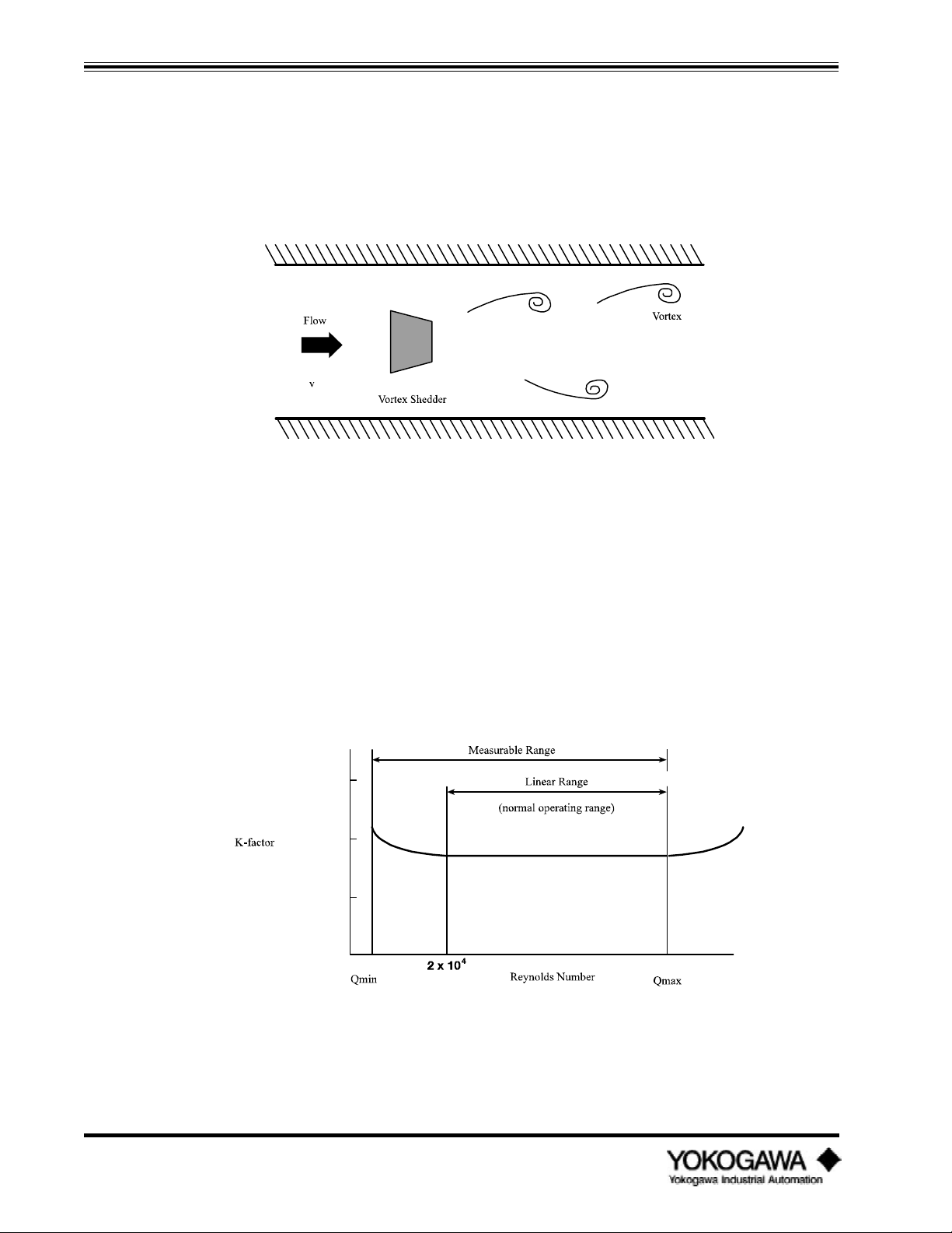
The flapping flag is a familiar example of vortex shedding that everyone should be comfortable with.
Here’ s how it’ s used in a vortex flowmeter. A non-streamlined part (bluff body) is inserted in the flow
stream, this obstruction in the pipe causes vortices to be alternately created (shed). We call this part
the ‘ shedder bar’ . The shedder bar in a YEWFLO performs two functions, it creates the vortices, and
with the addition of our piezoelectric crystals senses them too. The crystals generate an alternating
voltage waveform whose frequency is proportional to fluid velocity. The rest of the magic is taken care
of in the electronics.
Figure 1.2.1: Karman Vortices
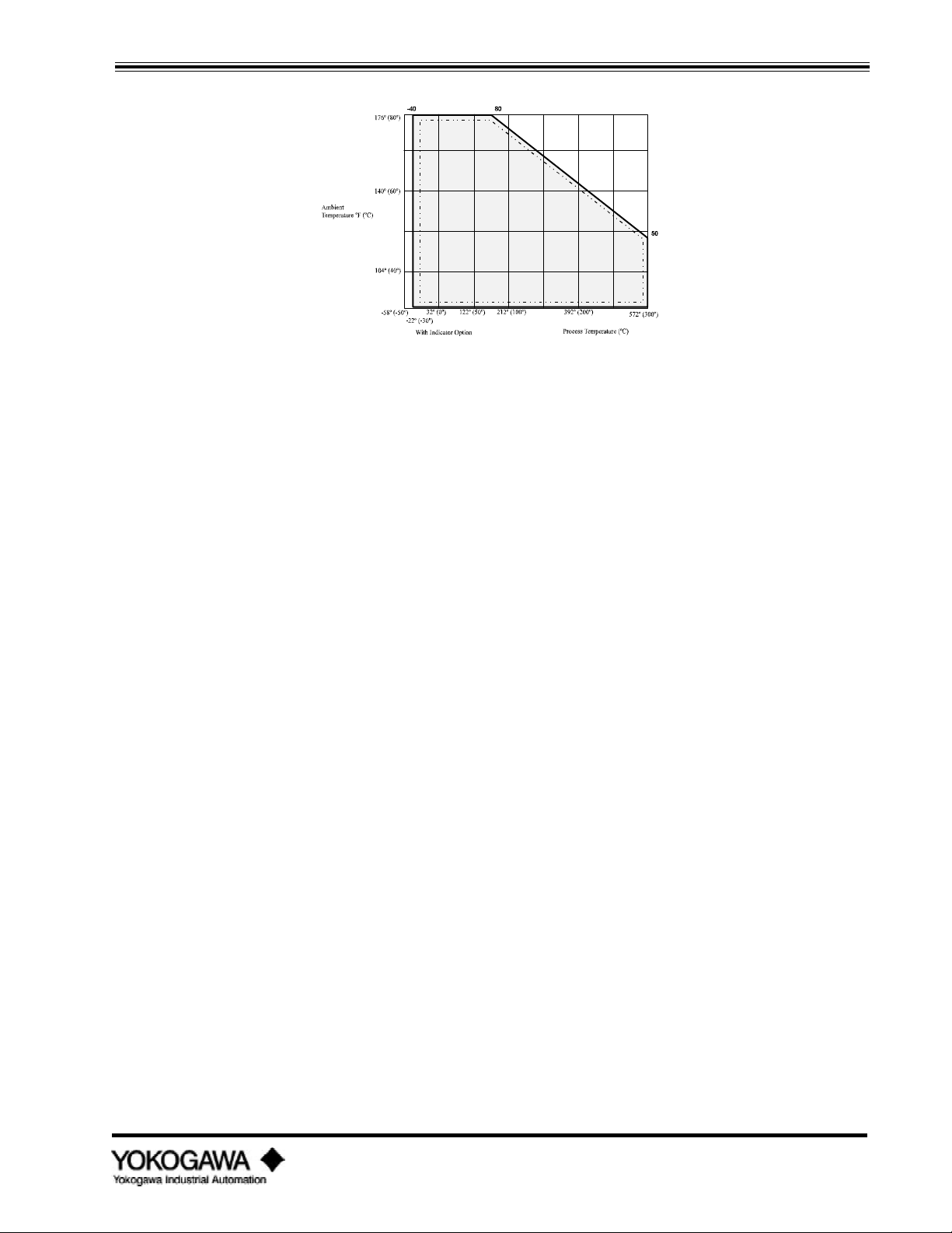
1.2.2 K-factor
The most important fact about vortex shedding is that once the physical geometry, (pipe I.D., shedder
bar width, etc.), are fixed, the frequency vs. flowrate (K-factor (pulse/gallon)) is unaffected by
changes in viscosity, density or pressure over the operating range of the specific application. To
determine the operating range use the YEWFLO Sizing program. On the other hand, an orifice plate is
directly affected by changes in any of these parameters. There is a very small temperature effect due to
expansion or contraction of the shedder bar width, which is easily compensated. Therefore, the Kfactor created in our flow stand (all YEWFLOs are wet flow calibrated) on water, is accurate for gas
too! Not so with an orifice plate. The benefit here is simplified calculations, and fewer things that
can effect accuracy .
IM 1F2B4-01-YIA
Page 2
Figure 1.2.2: Relationship between K-factor and Reynolds Numbers
Page 7

INTRODUCTION
1.2.3 Qmin
Those of you who haven’ t used many vortex flowmeters may be wondering, ‘ Why do we need to know
viscosity, density, pressure and temperature?’ . While the K-factor is unaffected by changes in
viscosity, density and pressure, the velocity at which vortices begin to be created and become stable
enough to measure accurately will vary. We refer to this velocity as Qmin, stated in desired flow units
GPM, SCFH, etc. Here’ s an example to help you understand. Let’ s go back to the flag example.
We’ ve all seen the flag flapping in the breeze; however, on some days we can feel the breeze blowing,
but the flag isn’ t flapping. Why not? For the flag to flap, there must be enough breeze blowing, or
energy, to lift the flag and create fully developed vortices. This is the same thing that happens in the
vortex flowmeter.
The higher the fluid viscosity, the higher the velocity (more energy) required to start vortex shedding.
On the other hand, the higher the density, the lower the velocity needed to start vortex shedding. In
gases, viscosity and density can vary with pressure and temperature. Sounds complicated, but
compared to an orifice plate it’ s quite simple. By using the YEWFLO sizing program, vortex meter
selection is simple. Simply enter the process conditions, the program will prompt you for them, and
presto, a performance table for all meter sizes is generated. This performance table will help you
select the best YEWFLO for the application.
1.2.4 Uniquely vortex
Vortex shedding flowmeters measure flow digitally. This means, amplitude of the vortex signal is
unimportant. As long as the flow is above the Qmin threshold, only the presence or absence of a
vortex is important. Just like digital electronics, as long as the voltage is above or below a threshold
value, it is either on or off. Digital flow measurement means no zero drift or span shift . Orifice plate
flowmeters, for example, cannot make this claim, even if they are using microprocessor-based digital
D/P transmitters, they still measure the small amplitude of deflection caused by differential pressure,
and changes in temperature or pressure can shift zero and span.
1.2.5 Vortex frequency
The YEWFLO uses piezoelectric crystals embedded in the shedder bar . Note that they are 1)
hermetically sealed, and 2) surrounded by a heavy wall thickness , to protect them from the
environment and the process. The positioning of the crystals is important. Although one crystal
primarily measures flow frequency, it unfortunately picks up some pipe vibration noise. The other
crystal is positioned such that it picks up primarily the pipe vibration noise. By electronically
subtracting these two signals, we are able to obtain a high signal to noise ratio for the flow signal .
The new Style "E" body design also improves the signal to noise ratio, by stiffening the shedder bar
mounting in the measurement plane, further isolating it from pipe vibration.
1.2.6 Available outputs
After processing the digital vortex frequency as described above, what outputs can you get? You can
select either 4-20 mA output or voltage pulse, digital output. Output is selected by setting jumpers on
the amplifier board, and the setting the software for pulse or analog output. Analog output is twowire, and pulse output is a three-wire connection (for details see the wiring section). The pulse output
can be scaled over a range of 0-6000 Hz, down or up to maximize pulse resolution. Scaling up the
frequency output can be done to improve resolution. The pulse output is also capable of driving many
electromechanical totalizers directly without additional power.
IM 1F2B4-01-YIA
Page 3
Page 8

INTRODUCTION
1.3 STANDARD SPECIFICATIONS
NOTE: For special applications, please contact your local Yokogawa Industrial Automation representative to
discuss possible enhancements to these standard specifications.
Fluids to be measured: Liquid, gas or steam
Performance specifications:
Repeatability: 0.2% of reading
Accuracy and velocity range :
Fluid Accuracy: Pulse Output Accuracy: Analog Output Velocity
Liquid ±0.8% of reading ±0.8% of reading plus up to 32 ft/sec
Gas or ±0.8% of reading ±0.8% of reading plus up to 115 ft/sec
Steam ±0.1% of full scale
±1.5% of reading ±1.5% of reading plus from 115 ft/sec
Note: Gas accuracy can be improved to 0.8% over the full range by built-in software compensation. (See
how to section 4.10.)
Output signal:
Analog: 4 to 20 mADC
Pulse: Low level 0 to 2 V
High level Vs - 2V ( Vs = input supply voltage)
Pulse width 50% duty cycle
±0.1% of full scale
±0.1% of full scale to 262 ft/sec
Ambient temperature limits:
-40º to 175ºF (-40º to 80ºC): standard unit w/o agency approval ratings
-20º to 175ºF (-30º to 80ºC): with optional digital indicator
-40º to 140ºF (-40º to 60ºC): with FM explosion-proof rating
-40º to 120ºF (-40º to 50ºC): with CSA intrinsically safe rating for integral converter
-40º to 175ºF (-40º to 80ºC): with CSA intrinsically safe rating for remote converter
Process temperature limits:
Standard remote converter: -40º to 575ºF (-40º to 300ºC)
HPT remote converter: -40º to 755ºF (-40º to 402ºC)
Cryogenic remote converter: -320º to 300ºF (-200º to 150ºC)
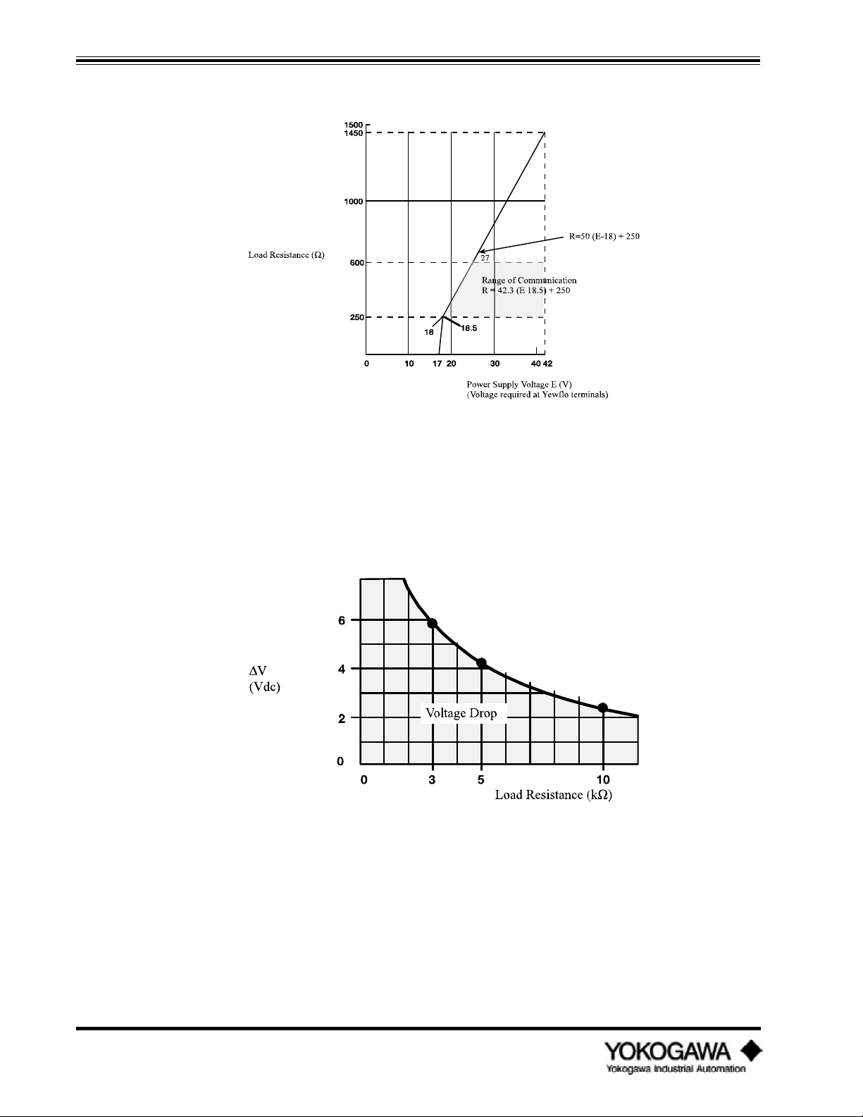
Integral converter: See Figure 1.3.1
Storage temperature limits:
Integral or remote standard unit: -40º to 176ºF (-40º to 80ºC)
With integral indicator or totalizer: -22º to 80ºF (-30º to 140ºC)
IM 1F2B4-01-YIA
Page 4
Page 9
INTRODUCTION
Figure 1.3.1: Operating temperature range for integral type converter
Power supply and load resistance:
Analog output: 17 to 42 VDC (see Figure 1.3.2)
Pulse output: 14 to 30 VDC
Maximum output wire resistance: 50 ohms
Maximum line capacitance: 0.22 microfarad
Ambient humidity limits:
5 to 100% relative humidity
Process pressure limits:
-14.7 psi (full vacuum) to flange rating
Materials of construction:
Process wetted parts:
Body: CF8M (ANSI 316 stainless steel) or Hastelloy C (equivalent of
ASTM494, CW12MW)
Shedder bar: Duplex stainless steel (CD4MCU equivalent to ANSI 329 stainless
steel) or Hastelloy C (equivalent of ASTM494, CW12MW)
Non-wetted parts:
Amplifier housing: Aluminum alloy casting
Paint: Case - Polyurethane resin baked coating, frosty white
Cover - Polyurethane resin baked coating, deep, sea moss green
IM 1F2B4-01-YIA
Page 5
Page 10
INTRODUCTION
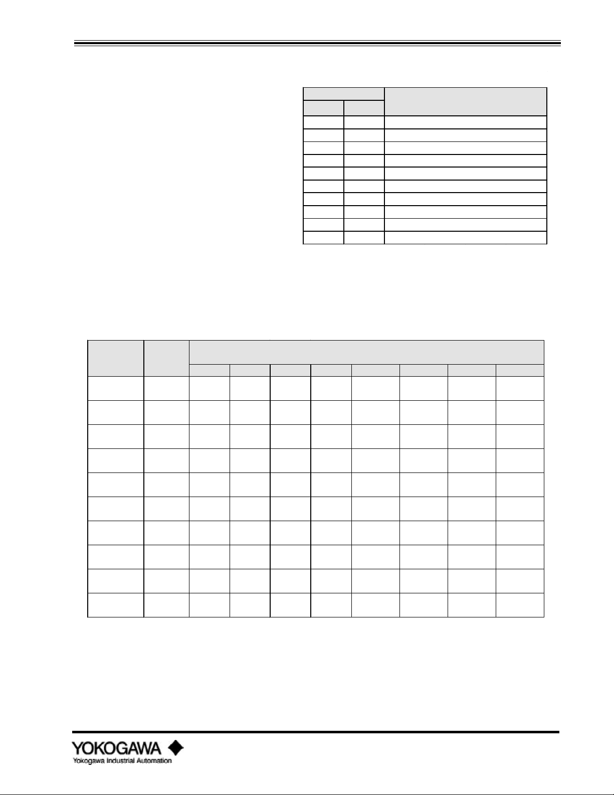
Analog Output :
Figure 1.3.2: Relationship between power supply voltage and load resistance for analog output version
Pulse Output: Pulse output voltage = Vs-2v-∆v
where ∆v = due to external load resistance
Vs = Power Supply Voltage
2v = 2 volts
IM 1F2B4-01-YIA
Page 6
Figure 1.3.3: Load resistance vs. pulse output voltage drop
Page 11
INTRODUCTION
1.4 BASIC SIZING
Measurable Flow Rates in U.S. gpm
Nominal Size
1.4.1 Flowmeter sizing
LIQUID
Nominal Size Minimum and Maximum
Notes: 1) This table assumes standard
conditions of 59ºF (15ºC).
2) Maximum flowrates are based
on 32 ft/sec.
3) These figures are
approximations. Refer to the
Yewflo sizing program for the
exact minimum and maximum
for your application.
4) The values shown in parenthesis
is the minimum linear flowrate.
5) Proper pipe bracing may be
required to obtain minimum
mm inch
15 ½ 1.3 -4.2 and 27
25 1 2 -7.3 and 82
40 1½ 5.9 -11.3 and 196
50 2 9.8 -14.5 and 324
80 3 20 and 628
100 4 33 and 1100
150 6 79 and 2400
200 8 150 and 4290
250 10 265 and 6460
300 12 300 and 9260
flowrate.
Table 1.4.1: Water -Flowmeter Range
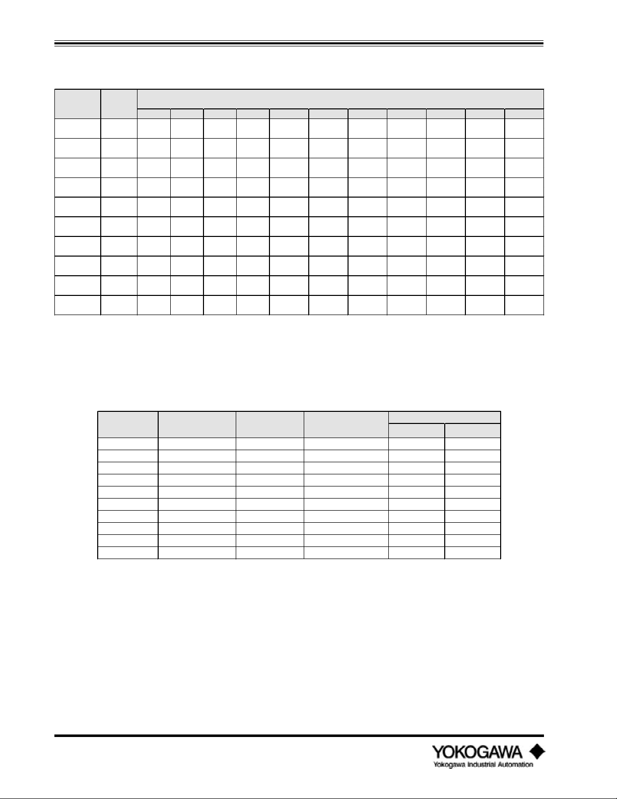
GAS
Flow Rate Minimum Linear and Maximum Measurable Air Flow Rates in SCFH
(inches) Limits (Standard conditions are 59ºF and 14.7 psia) at process line pressure
0 psig 50 psig 100 psig 150 psig 200 psig 300 psig 400 psig 500 psig
½ min 172 361 500 719 939 1379 1822 2266
max 1700 7492 13302 19128 24967 36692 48454 60266
1 min 400 839 1118 1486 1940 2851 3765 4683
max 5267 23215 41217 59268 77362 113692 150137 186737
1½ min 792 1919 3037 4061 5026 6838 8970 11157
max 1267 55397 98355 141428 184604 271296 358263 445599
2 min 1313 2756 4080 5867 7658 11254 14862 18485
max 20821 91779 162951 234313 305846 449474 593557 738253
3 min 2534 5321 7877 11326 14784 21726 28691 35685
max 40196 177182 314580 452347 590443 867720 1145876 1425214
4 min 4423 10710 16953 22670 28055 38174 50076 62283
max 70157 309249 549061 789516 1030544 1514497 1999984 2487535
6 min 9685 29678 46977 64927 84749 124548 164473 204567
max 153618 677145 1202247 1728757 2256524 3316208 4379250 5446812
8 min 20851 68121 107827 144185 178437 242799 303286 265774
max 274675 1010761 2149664 3091086 4034753 5929510 7830269 9739113
10 min 37370 122437 193804 259153 320716 436397 545115 649056
max 424752 1872295 3324193 4779987 6239253 9169263 12108556 15060351
12 min 53518 175343 277549 371134 459300 624968 780663 929518
max 608291 2681328 4760604 6845457 8935284 13131375 17340759 21568047
1
Notes: 1) Maximum flowrates are based on 262 ft/sec.
Table 1.4.2: Air-Flowmeter Range
2) These figures are approximations. Refer to the sizing program for the exact minimum and
maximum flowrates for your application.
IM 1F2B4-01-YIA
Page 7
Page 12
INTRODUCTION
STEAM
Nominal Size Flow Rate Minimum Linear and Maximum Measurable Saturated Steam Flow Rates in lb/hr
(inches) Limits
15 psig 25 psig 50 psig 75 psig 100 psig 125 psig 150 psig 175 psig 200 psig 250 psig 300 psig
½ min 12.8 14.6 18.4 21.5 24.1 26.5 28.7 30.7 32.6 36.6 43.4
max 122 161 254 346 437 527 616 705 765 973 1154
1 min 29.7 34 42.8 49.9 56.1 61.6 66.6 71.3 75.7 83.7 91.2
max 379 498 788 1071 1353 1632 1910 2185 2464 3014 357
1½ min 58.7 67.3 84.6 98.6 118 137 156 173 191 224 257
max 905 1188 1879 2554 3228 3894 4557 5215 5879 7192 8530
2 min 97.5 111 140 164 184 202 219 234 248 298 354
max 1500 1969 3113 4232 5349 6452 7550 8639 9740 11916 14133
3 min 188 216 271 316 355 390 422 452 480 576 683
max 2895 3800 6010 8170 10326 12455 14576 16678 18804 23004 27283
4 min 328 376 472 551 659 766 869 967 1065 1251 1434
max 5054 6633 10490 14260 18023 21739 25440 29109 32820 40150 47620
6 min 719 824 1184 1515 1827 2122 2407 2681 2951 3467 3974
max 11065 14523 22969 31224 39463 47600 55705 63739 71864 87914 104270
8 min 1549 1885 2720 3477 4193 4872 5525 6153 6773 7958 9122
max 19785 25968 41070 55830 70561 85111 99603 113968 128496 157194 186439
10 min 2725 3387 4888 6249 7536 8756 9930 11060 12174 14304 16396
max 30596 40157 63509 86334 109114 131614 154024 176238 198703 243081 288305
12 min 3903 4851 7000 8949 10793 12539 14220 15839 17434 20485 23481
max 43816 57590 90952 123640 156263 188485 220578 252392 284564 348119 412883
at process line pressure
Table 1.4.3: Steam - Flowmeter Range
Notes: 1) Maximum flowrates are based on 262 ft/sec.
2) These figures are approximations. Refer to the sizing program for the exact minimum and
maximum flowrates for your applications.
Nominal Size Internal Diameter Cross Sectional Nominal Pulse Rate Nominal K-factor
(inches) (inches) Area (ft2) (Hz/ft/s) Pulse/US gal Pulse/ft
½
1
1½
2
3
4
6
8
10
12
0.57 0.0018 19.1 1423 10645
1.01 0.0056 10.8 259 1940
1.56 0.133 7.05 70.8 530
2.01 0.022 5.59 33.9 253
2.8 0.043 4.02 12.6 94.3
3.69 0.074 3 5.39 40.3
5.46 0.163 2.03 1.67 12.5
7.31 0.291 1.52 0.7 5.24
9.09 0.45 1.23 0.366 2.74
10.9 0.645 1.03 0.213 1.59
Table 1.4.4: Nominal K-factor and general flowmeter information
3
IM 1F2B4-01-YIA
Page 8
Page 13
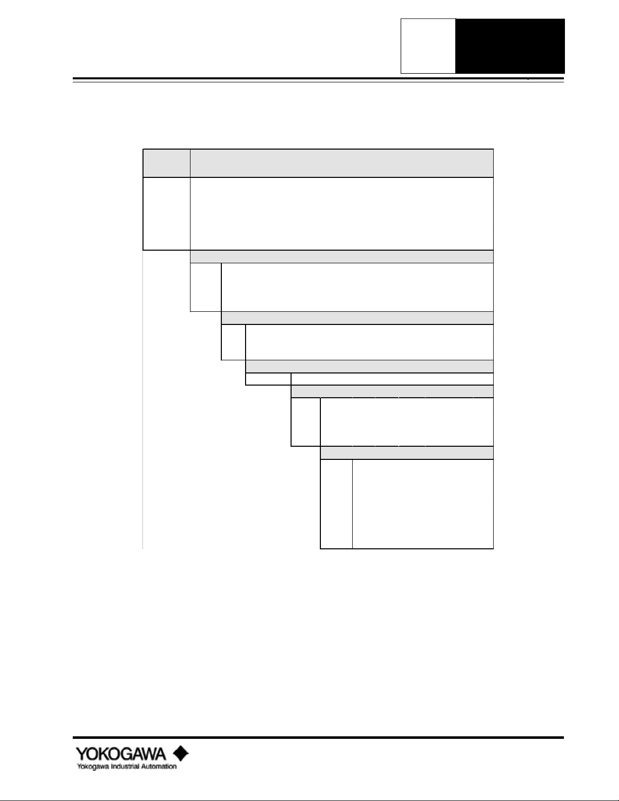
YEWFLO
B3
ANSI 600 lb Wafer Flanges
*E VORTEX FLOWMETERS
*E
STAINLESS
WAFER
MODEL
CODE
YF101 0.5" I.D. Stainless Steel Wafer
YF102 1.0" I.D. Stainless Steel Wafer
YF104 1.5" I.D. Stainless Steel Wafer
YF105 2.0" I.D. Stainless Steel Wafer
YF108 3.0" I.D. Stainless Steel Wafer
YF110 4.0" I.D. Stainless Steel Wafer
-AAU
-AAD Integral, 4-20 mA for intrinsic safety
-AAR Integral, pulse output for intrinsic safety
-NNN Remote converter
YEWFLO *E - STAINLESS WAFER
Integral , 4-20 mA or pulse
PROCESS CONNECTIONS (wafer style for mounting between)
ANSI 150 lb Wafer Flanges
B1
B2 ANSI 300 lb Wafer Flanges
A-S3S3*E
Stainless Steel shedder bar & body
/FMF
/FMS FM intrinsic safety w/FM stamp
/CSF CSA explosionproof housing w/CSA stamp
/CSS CSA intrinsic safety w/CSA stamp
CERTIFICATION
MATERIALS
CERTIFICATION
FM explosionproof housing w/FM stamp
OPTIONS
/HART
/HPT
/TBL
/EPF
/OSW
/BLT
/SCT
HART communications
High temperature
Local interface
Epoxy-coated electronics housing
Oxygen cleaning
304 SS nuts and bolts
Stainless Steel tags wired into place
IM 1F2B4-01-YIA
Page 9
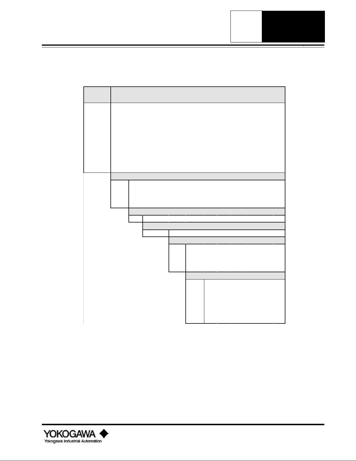
Page 14

STAINLESS
FLANGED 150#
*E
YEWFLO
*E VORTEX FLOWMETERS
MODEL
CODE
YF101 0.5" I.D. Stainless Steel 150 lb RF flange
YF102 1.0" I.D. Stainless Steel 150 lb RF flange
YF104 1.5" I.D. Stainless Steel 150 lb RF flange
YF105 2.0" I.D. Stainless Steel 150 lb RF flange
YF108 3.0" I.D. Stainless Steel 150 lb RF flange
YF110 4.0" I.D. Stainless Steel 150 lb RF flange
YF115 6.0" I.D. Stainless Steel 150 lb RF flange
YF120 8.0" I.D. Stainless Steel 150 lb RF flange
YF125 10.0" I.D. Stainless Steel 150 lb RF flange
YF130 12.0" I.D. Stainless Steel 150 lb RF flange
-AAU
-AAD Integral, 4-20 mA for intrinsic safety
-AAR Integral, pulse output for intrinsic safety
-NNN Remote converter
YEWFLO *E - STAINLESS 150# FLANGE
CONFIGURATION
Integral , 4-20 mA or pulse
PROCESS CONNECTIONS
ANSI 150 lb RF flanges
A1
A-S3S3*E
Stainless Steel shedder bar & body
/FMF
FM explosionproof housing w/FM stamp
/FMS FM intrinsic safety w/FM stamp
/CSF CSA explosionproof housing w/CSA stamp
/CSS CSA intrinsic safety w/CSA stamp
/HART
/HPT
/TBL
/EPF
/OSW
/SCT
MATERIALS
CERTIFICATION
OPTIONS
HART communications
High temperature
Local interface
Epoxy-coated electronics housing
Oxygen cleaning
Stainless Steel tags wired into place
IM 1F2B4-01-YIA
Page 10
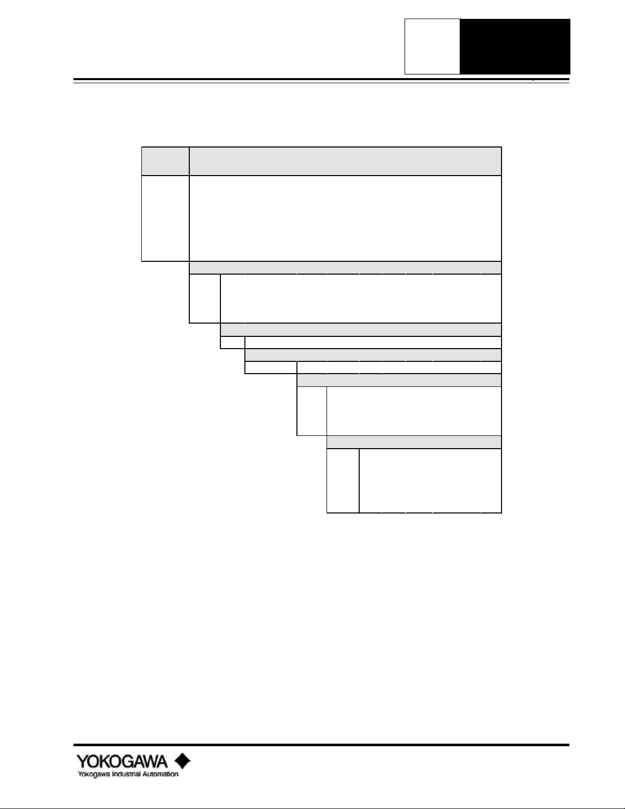
Page 15
YEWFLO
*E VORTEX FLOWMETERS
*E
STAINLESS
FLANGED 300#
MODEL
CODE
YF101 0.5" I.D. Stainless Steel 300 lb RF flange
YF102 1.0" I.D. Stainless Steel 300 lb RF flange
YF104 1.5" I.D. Stainless Steel 300 lb RF flange
YF105 2.0" I.D. Stainless Steel 300 lb RF flange
YF108 3.0" I.D. Stainless Steel 300 lb RF flange
YF110 4.0" I.D. Stainless Steel 300 lb RF flange
YF115 6.0" I.D. Stainless Steel 300 lb RF flange
YF120 8.0" I.D. Stainless Steel 300 lb RF flange
YF125 10.0" I.D. Stainless Steel 300 lb RF flange
YF130 12.0" I.D. Stainless Steel 300 lb RF flange
-AAU
-AAD Integral, 4-20 mA for intrinsic safety
-AAR Integral, pulse output for intrinsic safety
-NNN Remote converter
YEWFLO *E - STAINLESS 300# FLANGE
CONFIGURATION
Integral , 4-20 mA or pulse
PROCESS CONNECTIONS
ANSI 300 lb RF flanges
A2
A-S3S3*E
Stainless Steel shedder bar & body
/FMF
FM explosionproof housing w/FM stamp
/FMS FM intrinsic safety w/FM stamp
/CSF CSA explosionproof housing w/CSA stamp
/CSS CSA intrinsic safety w/CSA stamp
/HART
/HPT
/TBL
/EPF
/OSW
/SCT
MATERIALS
CERTIFICATION
OPTIONS
HART communications
High temperature
Local interface
Epoxy-coated electronics housing
Oxygen cleaning
Stainless Steel tags wired into place
IM 1F2B4-01-YIA
Page 11
Page 16

STAINLESS
FLANGED 600#
*E
YEWFLO
*E VORTEX FLOWMETERS
MODEL
CODE
YF101 0.5" I.D. Stainless Steel 600 lb RF flange
YF102 1.0" I.D. Stainless Steel 600 lb RF flange
YF104 1.5" I.D. Stainless Steel 600 lb RF flange
YF105 2.0" I.D. Stainless Steel 600 lb RF flange
YF108 3.0" I.D. Stainless Steel 600 lb RF flange
YF110 4.0" I.D. Stainless Steel 600 lb RF flange
YF115 6.0" I.D. Stainless Steel 600 lb RF flange
YF120 8.0" I.D. Stainless Steel 600 lb RF flange
-AAU
-AAD Integral, 4-20 mA for intrinsic safety
-AAR Integral, pulse output for intrinsic safety
-NNN Remote converter
YEWFLO *E - STAINLESS 600# FLANGE
CONFIGURATION
Integral , 4-20 mA or pulse
PROCESS CONNECTIONS
ANSI 600 lb RF flanges
A3
A-S3S3*E
Stainless Steel shedder bar & body
/FMF
FM explosionproof housing w/FM stamp
/FMS FM intrinsic safety w/FM stamp
/CSF CSA explosionproof housing w/CSA stamp
/CSS CSA intrinsic safety w/CSA stamp
/HART
/HPT
/TBL
/EPF
/OSW
/SCT
MATERIALS
CERTIFICATION
OPTIONS
HART communications
High temperature
Local interface
Epoxy-coated electronics housing
Oxygen cleaning
Stainless Steel tags wired into place
IM 1F2B4-01-YIA
Page 12
Page 17

YEWFLO
B3
ANSI 600 lb RF flanges
*E VORTEX FLOWMETERS
*E
HASTELLOY C
WAFER
MODEL
CODE
YF101 0.5" I.D. Hastelloy C Wafer
YF102 1.0" I.D. Hastelloy C Wafer
YF104 1.5" I.D. Hastelloy C Wafer
YF105 2.0" I.D. Hastelloy C Wafer
YF108 3.0" I.D. Hastelloy C Wafer
YF110 4.0" I.D. Hastelloy C Wafer
-AAU
-AAD Integral, 4-20 mA for intrinsic safety
-AAR Integral, pulse output for intrinsic safety
-NNN Remote converter
YEWFLO *E - HASTELLOY C WAFER
Integral , 4-20 mA or pulse
PROCESS CONNECTIONS (wafer style for mounting between)
ANSI 150 lb RF flanges
B1
B2 ANSI 300 lb RF flanges
A-HCHC*E
CERTIFICATION
MATERIALS
Hastelloy C Shedder wetted parts
CERTIFICATION
FM explosionproof housing w/FM stamp
/FMF
/FMS FM intrinsic safety w/FM stamp
/CSF CSA explosionproof housing w/CSA stamp
/CSS CSA intrinsic safety w/CSA stamp
OPTIONS
/HART
/TBL
/EPF
/OSW
/SCT
HART communications
Local interface
Epoxy-coated electronics housing
Oxygen cleaning
Stainless Steel tags wired into place
IM 1F2B4-01-YIA
Page 13
Page 18

HASTELLOY C
FLANGED 150#
*E
YEWFLO
*E VORTEX FLOWMETERS
MODEL
CODE
YF101 0.5" I.D. Hastelloy C 150 lb RF flange
YF102 1.0" I.D. Hastelloy C 150 lb RF flange
YF104 1.5" I.D. Hastelloy C 150 lb RF flange
YF105 2.0" I.D. Hastelloy C 150 lb RF flange
YF108 3.0" I.D. Hastelloy C 150 lb RF flange
YF110 4.0" I.D. Hastelloy C 150 lb RF flange
YF115 6.0" I.D. Hastelloy C 150 lb RF flange
-AAU
-AAD Integral, 4-20 mA for intrinsic safety
-AAR Integral, pulse output for intrinsic safety
-NNN Remote converter
YEWFLO *E - HASTELLOY C 150# FLANGE
CERTIFICATION
Integral , 4-20 mA or pulse
PROCESS CONNECTIONS (wafer style for mounting between)
ANSI 150 lb RF flanges
A1
A-HCHC*E
Hastelloy C Shedder wetted parts
/FMF
/FMS FM intrinsic safety w/FM stamp
/CSF CSA explosionproof housing w/CSA stamp
/CSS CSA intrinsic safety w/CSA stamp
MATERIALS
CERTIFICATION
FM explosionproof housing w/FM stamp
OPTIONS
/HART
/TBL
/EPF
/OSW
/SCT
HART communications
Local interface
Epoxy-coated electronics housing
Oxygen cleaning
Stainless Steel tags wired into place
IM 1F2B4-01-YIA
Page 14
Page 19
YEWFLO
*E VORTEX FLOWMETERS
*E
HASTELLOY C
FLANGED 300#
MODEL
CODE
YF101 0.5" I.D. Hastelloy C 300 lb RF flange
YF102 1.0" I.D. Hastelloy C 300 lb RF flange
YF104 1.5" I.D. Hastelloy C 300 lb RF flange
YF105 2.0" I.D. Hastelloy C 300 lb RF flange
YF108 3.0" I.D. Hastelloy C 300 lb RF flange
YF110 4.0" I.D. Hastelloy C 300 lb RF flange
YF115 6.0" I.D. Hastelloy C 300 lb RF flange
-AAU
-AAD Integral, 4-20 mA for intrinsic safety
-AAR Integral, pulse output for intrinsic safety
-NNN Remote converter
YEWFLO *E - HASTELLOY C 300# FLANGE
CERTIFICATION
Integral , 4-20 mA or pulse
PROCESS CONNECTIONS (wafer style for mounting between)
ANSI 300 lb RF flanges
A2
A-HCHC*E
Hastelloy C wetted parts
/FMF
/FMS FM intrinsic safety w/FM stamp
/CSF CSA explosionproof housing w/CSA stamp
/CSS CSA intrinsic safety w/CSA stamp
MATERIALS
CERTIFICATION
FM explosionproof housing w/FM stamp
OPTIONS
/HART
/TBL
/EPF
/OSW
/SCT
HART communications
Local interface
Epoxy-coated electronics housing
Oxygen cleaning
Stainless Steel tags wired into place
IM 1F2B4-01-YIA
Page 15
Page 20
NACE MTLS
B3
ANSI 600 lb RF flanges
WAFER
MODEL
CODE
YF101
YF102 1.0" I.D. NACE Wafer
YF104 1.5" I.D. NACE Wafer
YF105 2.0" I.D. NACE Wafer
YF108 3.0" I.D. NACE Wafer
7
*E
*E VORTEX FLOWMETERS
YEWFLO *E - NACE MATERIALS WAFER
METER SIZES
0.5" I.D. NACE Wafer
CERTIFICATION
-AAU
-AAD Integral, 4-20 mA for intrinsic safety
-AAR Integral, pulse output for intrinsic safety
-NNN Remote converter
Integral , 4-20 mA or pulse
PROCESS CONNECTIONS (wafer style for mounting between)
ANSI 150 lb RF flanges
B1
B2 ANSI 300 lb RF flanges
YEWFLO
A-HCS3*E
MATERIALS
Hastelloy C shedder bar w/stainless steel body
CERTIFICATION
FM explosionproof housing w/FM stamp
/FMF
/FMS FM intrinsic safety w/FM stamp
/CSF CSA explosionproof housing w/CSA stamp
/CSS CSA intrinsic safety w/CSA stamp
OPTIONS
/HART
/TBL
/EPF
/OSW
/SCT
HART communications
Local interface
Epoxy-coated electronics housing
Oxygen cleaning
Stainless Steel tags wired into place
IM 1F2B4-01-YIA
Page 16
Page 21

YEWFLO
*E VORTEX FLOWMETERS
*E
NACE MTLS
7
FLANGED 150#
MODEL
CODE
YF101 0.5" I.D. NACE 150 lb RF Flange
YF102 1.0" I.D. NACE 150 lb RF Flange
YF104 1.5" I.D. NACE 150 lb RF Flange
YF105 2.0" I.D. NACE 150 lb RF Flange
YF108 3.0" I.D. NACE 150 lb RF Flange
YEWFLO *E - NACE MATERIALS 150# FLANGE
-AAU
-AAD Integral, 4-20 mA for intrinsic safety
-AAR Integral, pulse output for intrinsic safety
-NNN Remote converter
Integral , 4-20 mA or pulse
PROCESS CONNECTIONS
ANSI 150 lb RF flanges
A1
A-HCS3*E
Hastelloy C shedder bar w/stainless steel body
/FMF
/FMS FM intrinsic safety w/FM stamp
/CSF CSA explosionproof housing w/CSA stamp
/CSS CSA intrinsic safety w/CSA stamp
CERTIFICATION
MATERIALS
CERTIFICATION
FM explosionproof housing w/FM stamp
OPTIONS
/HART
/TBL
/EPF
/OSW
/SCT
HART communications
Local interface
Epoxy-coated electronics housing
Oxygen cleaning
Stainless Steel tags wired into place
IM 1F2B4-01-YIA
Page 17
Page 22
NACE MTLS
7
FLANGED 300#
*E
YEWFLO
*E VORTEX FLOWMETERS
MODEL
CODE
YF101 0.5" I.D. NACE 300 lb RF Flange
YF102 1.0" I.D. NACE 300 lb RF Flange
YF104 1.5" I.D. NACE 300 lb RF Flange
YF105 2.0" I.D. NACE 300 lb RF Flange
YF108 3.0" I.D. NACE 300 lb RF Flange
YEWFLO *E - NACE MATERIALS 300# FLANGE
-AAU
-AAD Integral, 4-20 mA for intrinsic safety
-AAR Integral, pulse output for intrinsic safety
-NNN Remote converter
Integral , 4-20 mA or pulse
PROCESS CONNECTIONS
ANSI 300 lb RF flanges
A2
A-HCS3*E
Hastelloy C shedder bar w/stainless steel body
/FMF
/FMS FM intrinsic safety w/FM stamp
/CSF CSA explosionproof housing w/CSA stamp
/CSS CSA intrinsic safety w/CSA stamp
CERTIFICATION
MATERIALS
CERTIFICATION
FM explosionproof housing w/FM stamp
OPTIONS
/HART
/TBL
/EPF
/OSW
/SCT
HART communications
Local interface
Epoxy-coated electronics housing
Oxygen cleaning
Stainless Steel tags wired into place
IM 1F2B4-01-YIA
Page 18
Page 23
YEWFLO
*E VORTEX FLOWMETERS
*E
NACE MTLS
7
FLANGED 600#
MODEL
CODE
YF101 0.5" I.D. NACE 600 lb RF Flange
YF102 1.0" I.D. NACE 600 lb RF Flange
YF104 1.5" I.D. NACE 600 lb RF Flange
YF105 2.0" I.D. NACE 600 lb RF Flange
YF108 3.0" I.D. NACE 600 lb RF Flange
YEWFLO *E - NACE MATERIALS 600# FLANGE
-AAU
-AAD Integral, 4-20 mA for intrinsic safety
-AAR Integral, pulse output for intrinsic safety
-NNN Remote converter
Integral , 4-20 mA or pulse
PROCESS CONNECTIONS
ANSI 600 lb RF flanges
A3
A-HCS3*E
Hastelloy C shedder bar w/stainless steel body
/FMF
/FMS FM intrinsic safety w/FM stamp
/CSF CSA explosionproof housing w/CSA stamp
/CSS CSA intrinsic safety w/CSA stamp
CERTIFICATION
MATERIALS
CERTIFICATION
FM explosionproof housing w/FM stamp
OPTIONS
/HART
/TBL
/EPF
/OSW
/SCT
HART communications
Local interface
Epoxy-coated electronics housing
Oxygen cleaning
Stainless Steel tags wired into place
IM 1F2B4-01-YIA
Page 19
Page 24
REMOTE
CONVERTER
*E
YEWFLO
*E VORTEX FLOWMETERS
MODEL
CODE
YFA11 Remote Converter
-AUPA
-ADPA 4-20 mA for intrinsic safety
-ARPA Pulse output for intrinsic safety
YEWFLO *E - REMOTE CONVERTER
4-20 mA or pulse output
-01*E 0.5" body
-02*E 1.0" body
-04*E 1.5" body
-05*E 2.0" body
-08*E 3.0" body
-10*E 4.0" body
-15*E 6.0" body
-20*E 8.0" body
-25*E 10.0" body
-30*E 12.0" body
CONFIGURATION
METER SIZES
CERTIFICATION
/FMF
/FMS FM intrinsic safety w/FM stamp
/CSF CSA explosionproof housing w/CSA stamp
/CSS CSA intrinsic safety w/CSA stamp
FM explosionproof housing w/FM stamp
OPTIONS
/HART
/TBL
/EPF
/SCT
/Z
HART communications
Local interface
Epoxy-coated electronics housing
Stainless Steel tags wired into place
Additional cable, per foot
IM 1F2B4-01-YIA
Page 20
Page 25
YEWFLO
*E VORTEX FLOWMETERS
CABLE TYPE, *E
YF011 Remote meter interconnecting cable
CONFIGURATION
-1
Terminated ends
-0010F
-0015F 15 feet
-0030F 30 feet
-0050F 50 feet
-0065F 65 feet
METER SIZES
10 feet
CERTIFICATION
*E Style E
*E
PARTS
METERS
CABLE
IM 1F2B4-01-YIA
Page 21
Page 26

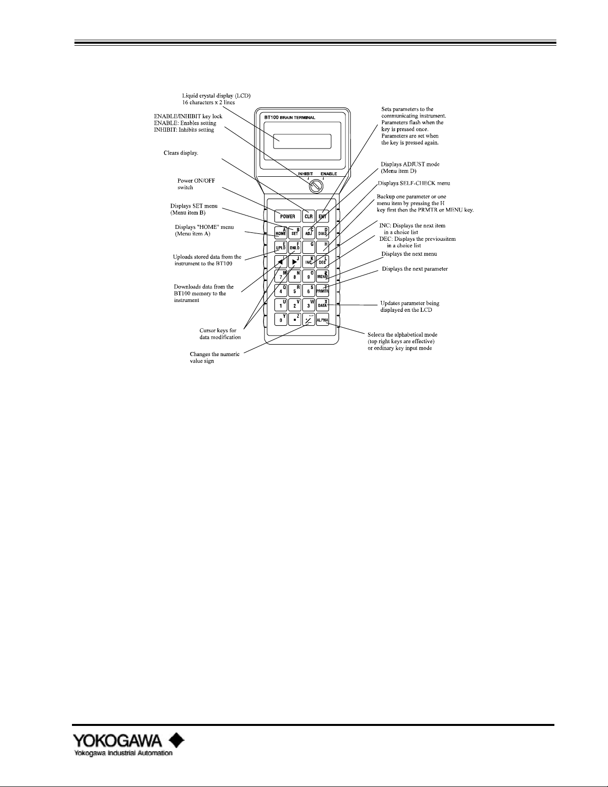
QUICK START USING THE BT100/200
II. QUICK START
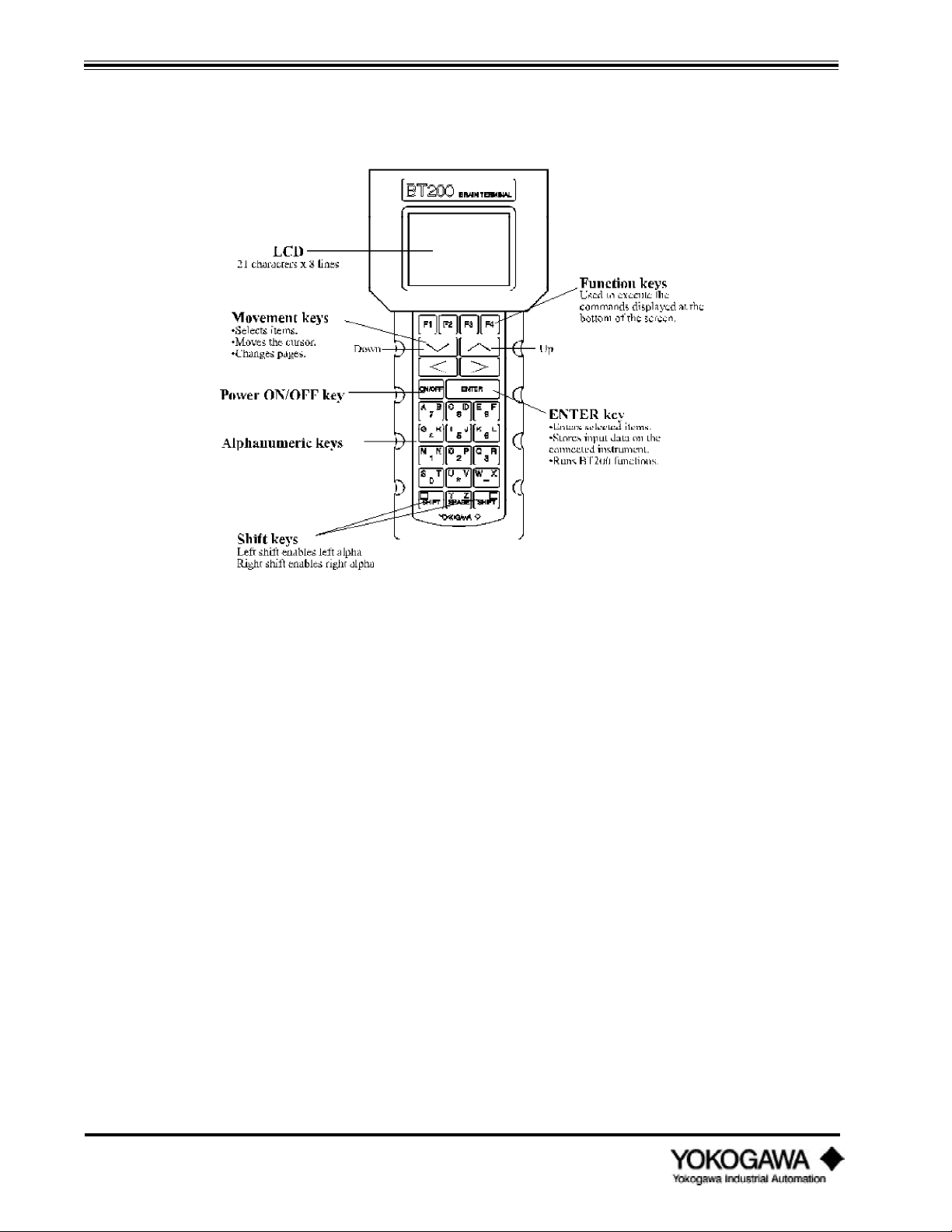
BT100/BT200 HANDHELD TERMINAL
Note: If you specified the correct process conditions on your order, these parameters have been preset at the
factory; therefore, there is no need to re-enter the data.
The Style E YEWFLO is a smart communicating device with microprocessor-based technology.
When used with Yokogawa’ s BT100 or BT200 handheld terminal (HHT), YEWFLO can be
configured to meet specific application needs. In addition, the optional local indicator/totalizer (TBL
option) allows setting of various parameters.
When in the analog output mode, the HHT may be connected at any point on the instrument's
4-20 mA loop. This connection superimposes a digital signal on top of the instrument’ s 4-20 mA
signal making communications completely transparent to your process signal. On the other hand,
since there are no 4-20 mA wires in the pulse mode, direct connection of the HHT to the HHT
PULSE and HHT COM test points on the amplifier is necessary. Once connected, flowrate and total
can be read, tag numbers entered, meter size or any other parameter modified as required.
Additionally, you may activate or deactivate many features of the YEWFLO as necessary to meet
the requirements of your application.
The HHT will enable you to scroll through the program until you locate the parameter that you wish
to change. For communication information, see “How to communicate with the YEWFLO remotely”
in the maintenance section. Please refer to the appropriate HHT instruction manual for details on
each HHT.
To change a parameter using the BT100, insert the removable key in the lock and turn it clockwise
to the ENABLE position. If the key is not in place or if it is in the INHIBIT position, you will receive an
OPERATION ERR message on the display when you press either the I NC or DE C key or try to enter
an alphanumeric value in any parameter. If this occurs, insert the key in the lock, turn it clockwise to
the ENABLE position then press either the I N C , DE C or alphanumeric key as before.
2.1 PARAMETER SETTING IN BRAIN™ COMMUNICATIONS
The Model YF100*E Vortex flowmeter incorporates BRAIN™ communication functions. These
functions enable the Vortex converter to remotely carry out the following functions by
communicating with the BRAIN™ Terminal (BT100 or BT200), µXL, or Centum-XL distributed
control systems.
• Setting or changing parameters required for vortex meter operation such as tag number, flow span
and process conditions for example.
• Monitoring flowrate, totalized flow and self-diagnostics.
• 4-20 mA loop check (simulated output) and totalizer reset.
Note: When the pulse/analog jumpers are set for a pulse output, Remote BRAIN™ communication on the
4-20 mA wires is not available. Therefore parameters cannot be set or read remotely. For the BT100
to operate in the pulse output mode, the instrument must be connected to the test points labeled HHT
Pulse and HHT Com. This allows access to all parameters.
Note: Only the position of the jumpers affects remote communication ability, the software setting of pulse or
4-20 mA has no effect.
IM 1F2B4-01-YIA
Page 22
Page 27
QUICK START USING THE BT100/200
BT100 Basic Operation
1) POWER on.
2) First three key strokes will always display “Model No.” , Tag No.”, and “Self-check” .
3) Press ME N U key to select desired main menu.
4) Press P MT R key to move down through the selected menu.
5) Once a parameter has been selected, use the I NC or D E C keys to review options within the
parameter list. When data input is required, use the al pha key to toggl e between the al pha an d
n umeri c character s (A to Z, 0 to 9).
6) Once a parameter has been selected, push E NT twice to save the changes.
Notes: A ) Use the AL P H A key to move between al pha a n d n umeri c char acter s.
B) To back up i n t he pr ogr ammi n g sequen ce, push H key an d then P MT R when i n par amet er
mode or ME N U when i n mai n men u mode.
C) UP L D and DN L D keys permit copying settings from one instrument in BT100 non-volatile
memory to another instrument.
D) The automatic power-off of the BT100 automatically turns off the power when no key has been
pressed for about 5 minutes. This function is not active during the display A10: Flowrate %, A20:
Flowr ate, or A30: Total. The display of these values is updated every 5 seconds.
IM 1F2B4-01-YIA
Page 23
Page 28
QUICK START USING THE BT100/200
BT200 Ba si c Operati on
1) Pr ess ON/OFF to acti vate power .
2) Pr ess E N T E R key when pr ompt ed.
3) “Model ”, “Tag N o.”, an d “Sel f-check” wi l l al ways be di splayed n ex t.
4) Pr ess F 4 to conti n ue. The mai n men u l i st wi l l be di splayed n ex t.
5) Hi ghl ight the desi red men u b y usi n g the up an d down movemen t ke ys. P r ess E NT E R to
access the sel ected men u.
6) Use the up an d down movemen t ke ys to hi ghl i ght the desi red parameter an d pr ess E NT E R to
access.
7) On ce a parameter has been sel ect ed ei ther:
a) Use the up an d down movemen t ke ys to r evi ew opti on s wi thi n t he par ameter . On ce the
appr opri ate opti on has b een sel ected, press E NT E R twice to edi t the sel ecti on .
b) Wher e data i n put i s requi r ed, use the al pha key to toggl e between t he al pha an d n umer i c
character s. Pr ess E NT E R twice to save the chan ges.
N otes: A ) The fun cti on keys (F 1 -F 4 ) ar e used to ex ecute the comman d s di s pl ayed at the bottom of the
scre e n .
B) Use the left (<) and right (>) movement keys to change whole page of displayed information. The
“ <“ key shows the preceding page and the “ >“ key the following page.
C) To select a desired alpha character, always use the appropriate S HI F T key. Use the green
shift key to select letters marked in green and the black shift key to select letters marked in black.
If the alpha/numeric keys are not used in conjunction with the S HI F T key, the numeric value
shown on the key will be displayed.
D) To go directly to a particular parameter anywhere in the menu tree while working in a menu, press
either S HI F T key and then press F 4 . Type the parameter designation (example B24) to be
displayed and press E NT E R .
IM 1F2B4-01-YIA
Page 24
Page 29

QUICK START USING THE BT100/200
2.2 YEWFLO SETUP
Note: If you specified the correct process conditions on your order, these parameters have been preset at the
factory; therefore, there is no need to re-enter the data.
The purpose of a Quick Start is to address only those parameters which must be set to establish the
operation of a meter for this application. Follow the parameters listed below and enter the data for
your particular application.
With the BT100 or BT200 properly connected to the Vortex meter begin communicating by pressing
the power button. After the power up sequence is complete, go to “ Menu B: SET 1” . The operation of
the BT100 and BT200 are slightly different. Please refer to the ‘ Basic Handheld Terminal Operation’
if you are unfamiliar with how to move through the menus and parameters. The following flow chart
identifies only the parameters to be set, you may have to skip several parameters or menus to get to
the parameters shown below. Be sure to enter all values and selections shown below or they will
not be saved. If you make a typing error, use the CL R key to clear and re-enter.
IM 1F2B4-01-YIA
Page 25
Page 30

QUICK START USING THE BT100/200
2.3 PARAMETER SETTING IN HART™ COMMUNICATIONS
When specified, the model YF100*E vortex flowmeter can be provided with HART™
communication functions. (To determine if this field communication protocol has been
incorporated in your instrument, confirm the “HART” suffix is a part of the YEWFLO model code.)
These functions enable the vortex converter to remotely carry out the following by communicating
with the HART communicator:
· Setting or changing parameters required for vortex meter operation such as tag number, flow span
and process conditions.
· Monitoring flowrate, totalized flow and self-diagnostics.
· 4-20 mA loop check (simulated output) and totalizer rest
The HART communicator can interface with YEWFLO from the control room, via direct connection
to the amplifier, or any other wiring termination point on the 4-20 mA loop. Polarity does not matter.
There must be a minimum of 250 ohms between the connection and the power supply. Refer to
Figure 1.3.2 on page 7 for power supply voltage requirements and load resistance.
Note1: The output jumpers on the amplifier must be set to the analog position to communicate. Only the
position of the jumpers affects remote communication ability, the software setting of pulse or 4-20 mA
has no effect.
Note2: When Yewflo is supplied with the HART option, the TBL digital display/local operator interface
cannot be used for parameter setting and configuration. Only two parameters are supported by the
TBL:
Parameter E01: Total reset
Parameter E02: Display Select
The amplifier has been pre-configured at the factory, so no setup should be required prior to
installation. If your process conditions have changed and reprogramming is required, the menu/
parameter configuration list for YEWFLO/HART can be found in Appendix B in the back of this
manual. Refer to the instructions provided with your HART communicator or operation details. The
QUICK START section of this manual will address only those parameters which must be set to
establish the operation of the meter for a particular application. Appendix B will cross-reference the
BRAIN parameters to the corresponding HART parameters.
2.3.1 Communication Specifications
Method of communication: Frequency shift keying (FSK). Conforms with Bell 202 Modem standard
with respect to baud rate and digital “ 1” and “ 0” frequencies.
Baud Rate: 1,200 bps
Digital “0” Frequency: 2,200 Hz
Digital “1” Frequency: 1,200 Hz
Data Byte Structure: 1 start bit, 8 data bits, 1 odd parity bit, 1 stop bit
IM 1F2B4-01-YIA
Page 34
Page 31

QUICK START USING THE BT100/200
Single Digital Process Variable Rate:
Poll/Response Mode: 2.0 per second
Burst Mode: 3.7 per second
Maximum Number of Multi-drop Devices:
Loop Powered: 15
Multivariable Specification:
Maximum process variable per smart device: 256
Maximum Number of Communication Masters: Two
2.3.2 Hardware Recommendations:
Supply Voltage: 17-42 VDC
Load Resistance: 250 to 600 ohms (includes cable resistance)
Refer to Figure 1.3.2 on page 7 for power
supply voltage requirements and load
resistance.
Minimum cable size: 24 AWG, (0.51 mm diameter)
Cable Type: Single pair shielded or multiple pair with
overall shield
Maximum Twisted-Pair Length: 10,000 ft. (3,048 m)
Maximum Multiple Twisted-Pair Length: 5,000 ft (1,524 m)
Use the following formula to determine cable length for a specific application:
L = 65 x 106
(R x C) C
where:
- (Cr + 10,000)
L = length in feet or meters
R = resistance in ohms (current sense resistance plus barrier resistance)
C = cable capacitance in pF/ft or pF/m
Cf = maximum shunt capacitance of field device in pF
IM 1F2B4-01-YIA
Page 35
Page 32

INSTALLATION
III. INSTALLATION
Before installing your YEWFLO you will need to gather the following tools:
Wafer Style:
1. Gaskets - self-centering preferred. In no case should the I.D. of the gaskets be smaller than
the I.D. of the meter.
2. Wrenches - Two of a size appropriate for the nuts supplied.
3. Screw driver - A small Phillips or flat blade type may be used to connect lead wires.
4. Sufficient wire to reach from the meter signal converter to the power source, receiving
device. See the Wiring Section of this manual for wire recommendations.
5. Stud bolts, washers and nuts are supplied with the meter
Flanged Style:
1. Nuts, bolts and washers appropriate in type, size, material and quantity for the flange as
specified by ANSI standards.
2. Gaskets - self-centering preferred. In no case should the I.D. of the gaskets be smaller than
the I.D. of the meter.
3. Wrenches - Two of a size appropriate for the nuts supplied.
4. Screw driver - A small Phillips or flat blade type may be used to connect lead wires.
5. Sufficient wire to reach from the meter signal converter to the power source, receiving
device. See the Wiring Section of this manual for wire recommendations.
3.1 PIPING REQUIREMENTS
To obtain maximum performance, the vortex flowmeter should be installed in a pipe with a straight
run the same size as the nominal size of the meter. On the upstream side, the straight run depends on
what is in the pipe ahead of the meter. In most installations a maximum of 20 diameters will be
sufficient. The pipe on the downstream side of the meter should always be at least 5 diameters. The
combination of flowmeter with upstream and downstream pipe is referred to as the metering run.
Refer to the following illustrations for the minimum straight pipe for your installation. Note that in
all installations the mating pipe on either side of the vortex meter must match the meter size. In many
applications proper sizing may recommend using one meter size smaller than the existing pipe.
When this is the case, concentric reducers should not be directly attached to the flowmeter, but
installed on either end of the metering run as shown. In any case, the guidelines for orifice plate
installations as published by the ASME will be safe to follow.
IDEAL
Figure 3.1.1: YEWFLO upstream side of valve
IM 1F2B4-01-YIA
Page 36
Page 33

INSTALLATION
ACCEPTABLE
Figure 3.1.2: Reducer, expander, elbow and valve
If the meter cannot be located in the piping where the minimum straight run requirements can be
met, it may be possible to install flow conditioning equipment upstream of the vortex meter and
reduce the upstream piping without significantly reducing the accuracy. Contact your local
representative or Yokogawa Industrial Automation for recommendations regarding flow conditioners.
3.1.1 Pipe schedule
We recommend pipe schedule 40 for ½" through 2" meter sizes. For meters larger than 2", use
schedule 80 pipe or smaller. If pipe schedule other than above is used, please refer to Parameter D05
to correct errors due to mismatched pipe schedule.
3.1.2 Flow direction and orientation
Before installing the vortex meter verify the arrow on the meter body is facing the same
direction as the direction of the flow. The direction of flow can be determined by the arrow on the
shedder bar or clamping plate. The meter may be installed with the converter located above, below
or to the side of the piping, whatever suits the selected installation location best. Flow may be
horizontal or vertical, as long as the pipe is completely full. For liquid applications vertical flow up
is preferred, as this guarantees a full pipe at all times.
3.1.3 Pressure and temperature taps
If you are metering a gas where pressure and temperature compensation is required, pressure and
temperature taps must be located downstream of the vortex meter. See Figure 3.1.3.
Figure 3.1.3: Pressure and Temperature taps
IM 1F2B4-01-YIA
Page 37
Page 34

INSTALLATION
3.1.4 Flushing the pipe
On a new installation we recommend flushing the pipeline and removing any and all scales on the
inside of the pipe before installing the vortex meter. The bypass piping should be installed around the
vortex meter to facilitate pipe cleaning. When there is no bypass piping, the vortex meter should be
temporarily removed and a spool piece installed in its place.
3.1.5 Gaskets
The ID of the gaskets must be equal to or larger than the ID of the meter and mating pipe. The
gaskets should be the self-centering type. It is important that the gaskets not protrude into the flow
stream, otherwise accuracy will be adversely affected.
Figure 3.1.4: Gasket cross section Figure 3.1.5: Typical gasket with bolt holes
3.2 INSTALLING THE VORTEX METER
Before installing the vortex meter, verify the arrow on the meter body is facing the same direction as
the direction of the flow.
3.2.1 Installing the wafer style vortex meter
When installing the wafer type vortex meter it is important to align the instrument bore with the
inner diameter of the adjacent piping. For meters in sizes ½" through 3", four alignment collars are
supplied. These collars establish a predetermined spacing between the mounting bolts and the
outside diameter of the vortex meter body. The bolts must be of the proper diameter to establish
alignment. Carbon steel stud bolts and nuts are supplied as standard. Stainless steel (304) stud bolts
and nuts are optional. Gaskets are supplied by the user. Check all mating flanges ensuring all weld
slag is ground off and the inside surface is clean and smooth.
IM 1F2B4-01-YIA
Page 38
Page 35

INSTALLATION
Meter Flange Collar Kit Mark on
Size Rating (4 per set) collar
0.5" 150# F9322GC GL
0.5" 300#, 600# F9322GD GM
1.0" 150# F9322HC HL
1.0" 300#, 600# F9322GA GJ
1.5" 150# F9322GC GL
1.5" 300#, 600# F9322JD JM
2.0" 150# F9322KA KC
3.0" 150# F9322KM KP
Table 3.2.1: Dimensions
Note: Only the above indicated meter sizes require collars
3.2.2 Installing the wafer style vortex meter horizontally
1) Insert two collars (see dimensions table above) on each of the two lower bolts.
2) Place the vortex meter on the collars located on the lower two bolts making sure the arrow
on the side of the meter body is facing in the same direction as the flow.
3) Insert the remaining bolts and tighten all bolts and nuts uniformly.
4) Check for leakage between the meter body and the flanges.
Figure 3.2.1: Wafer type - horizontal installation
3.2.3 Installing the wafer style vortex meter vertically
1) Insert one collar (if required, see table 3.2.1) on each bolt, being certain that the collars are
in contact with the outside diameter of the vortex meter body. Make sure the arrow on the
side of the meter body is facing the same direction as the flow.
2) Tighten all bolts uniformly.
3) Check for leakage between the meter body and the flanges.
IM 1F2B4-01-YIA
Page 39
Page 36

INSTALLATION
CAUTION:
When installing the vortex meter in a vertical pipe
outdoors we recommend rotating the conduit
connection to face downward reducing the chance of
rain and condensate running down the conduit into
the housing.
Fig 3.2.2: Wafer type - vertical installation
3.2.4 Installing the flanged vortex meter
Use bolts, nuts and gaskets in accordance with ANSI B16.5 (user supplied). The ID of the gasket
must be equal to or greater than the ID of the meter bore. Self-centering gaskets are highly
recommended.
Figure 3.2.3: Flanged type - horizontal installation Figure 3.2.4: Flanged type - vertical installation
3.2.5 Insulating vortex meters with integral converter
When installing a vortex meter with an integral converter in a pipe to measure high temperature
fluids, do not insulate the converter housing or mounting bracket. If it is necessary to insulate the
entire installation, use a remote mounted converter. Custom steam jackets are available if necessary,
please contact your Yokogawa Industrial Automation Representative for more information.
IM 1F2B4-01-YIA
Page 40
Page 37

INSTALLATION
3.2.6 Rotating the meter housing
The terminal box or converter housing may be rotated in 90º increments with respect to the pipe for
viewing or wiring convenience.
3.2.7 Remote converter terminal box rotation
1) Turn the power off.
2) Remove the terminal box cover.
3) Disconnect the lead wires from the sensor, Red (A) and White (B).
4) For 1" through 4" meter sizes, remove the bracket mounting bolts and the terminal box from
the meter body. Remove the four Allen bolts securing the terminal box to the bracket,
rotate to the desired position and reassemble.
5) On larger meters remove the 4 hex bolts securing the terminal box, rotate to the desired
position and reassemble.
3.2.8 Integral converter rotation
1) Turn the power off.
2) Remove the converter cover.
3) Remove the amplifier.
4) Disconnect the wires from the sensor, Red (A) and White (B).
5) For 1" through 4" meter sizes, remove the bracket mounting bolts and the amplifier housing
6) On larger meters remove the 4 hex bolts securing the amplifier housing, rotate to the desired
Figure 3.2.5: Changing the terminal box orientation
from the meter body. Remove the four Allen bolts securing the housing to the bracket, rotate
to the desired position and reassemble.
position and reassemble.
IM 1F2B4-01-YIA
Page 41
Page 38

INSTALLATION
Figure 3.2.6: Changing the converter orientation
3.2.9 Installing the remote converter
A special signal cable (YF011) must
be used between the vortex meter body and the remote
electronics. The maximum cable length is 65 feet (20 meters). Do not splice additional cable to
extend the length. The converter may mounted on 2" nominal pipe stand (horizontal or vertical)
using the supplied mounting bracket. The converter orientation may be rotated in 90º increments if
necessary to simplify wiring or viewing. To shorten the cable in the field please refer to the section
on cable.
Figure 3.2.7: Converter installation Figure 3.2.8: Converter installation
vertical pipe mounting horizontal pipe mounting
Note: If there is a local indicator (option /TBL) included on the remote amplifier, its display may be rotated
IM 1F2B4-01-YIA
Page 42
in 90º increments to facilitate reading the display.
Page 39

INSTALLATION
3.3 WIRING
3.3.1 Cables and wires (analog or pulse output wires only)
The following recommendations should be considered when selecting output wire for YEWFLO, and
installing it in the field.
1) Use 600 V PVC insulated wire or equivalent.
2) Use shielded wire in areas susceptible to electrical noise.
3) Use wire and cable suitable for the ambient environment, especially temperature and
4) Lay wires as far as possible from electrical noise sources such as large transformers, motors,
5) When wiring in a vertical position, a drip loop with a drain should be installed in the conduit
6) We recommend using crimp-on solderless type lugs for the output wire termination.
7) For industrial installations, we recommend using conduit or cable tray to protect wiring from
8) Safety grounding should meet National Electrical Code Class 3 requirements (resistance to
3.3.2 Analog output, 2-wire type (4-20 mADC)
When configured for analog output, the two instrument output wires also provide power. A DC
power supply (user supplied) is required in the loop. The power supply voltage required is
determined by the total instrument loop resistance including output wires. The permissible resistance
versus required power supply voltage is shown in figures 3.3.1 and 3.3.2.
chemical compatibility.
and power supplies.
so that water does not run down the wire and into the converter housing.
water or mechanical damage. A rigid steel conduit or flexible metal conduit is acceptable.
ground of 100 ohms or less). Ground wires should be 600 V PVC insulated wire.
Note: The field chassis ground and minus (-) power supply terminal are isolated from each other and should
not be connected.
Figure 3.3.1: Wiring Connections (Analog) Remote Converter
IM 1F2B4-01-YIA
Page 43
Page 40

INSTALLATION
Figure 3.3.2: Wiring Connections (Analog) Integral Converter
3.3.3 Pulse output, 3-wire type
When configured for pulse output mode, the converter requires three wires between the converter
and the power supply. The required power should be between 18 and 30 VDC (allowable ripple +1.5
V or less). The pulse output (P terminal) is connected to a remote totalizer. The minimum load
resistance of the pulse output loop is 10k ohms (maximum capacitance 0.22F, 0.1F for output
frequency above 2.5 kHz), and interconnection wire resistance must be less than 50 ohms.
IM 1F2B4-01-YIA
Page 44
Figure 3.3.3: Wiring Connections (Pulse) - Remote Converter Type
Page 41

INSTALLATION
Figure 3.3.4: Wiring Connections (Pulse) - Integral Type
3.3.4 Interconnection for remote converter
When the converter is remotely mounted from the meter body, a special signal cable (YFO11) must
be used. The maximum length of this cable is 65 feet (20 meters). The signal cable transmits a low
level sensor signal from the remote flowmeter to the remote converter. The remote converter
provides the output signals as described above. The remote signal wire connections are the same for
either Analog or Pulse output units. The A, B and C terminals on the flowmeter are connected via the
red, white and black wires (respectively) to the A, B and C terminals on the converter. The blue wire
is connected on the converter end only to chassis ground. See figure 3.3.5.
For remote mounted converters there are two electrical conduit connections. Use the left connection,
as viewed from the terminal side, for the signal wire (YFO11 cable) and the right connection for the
output wiring. If the connection directions are reversed, the cover shield for the signal terminals
cannot be installed.
Figure 3.3.5: Shield Converter -Remote Type
IM 1F2B4-01-YIA
Page 45
Page 42

INSTALLATION
3.4 CABLE
3.4.1 Field terminating the signal cable (YF011-0*E)
Both ends of the cable must be finished in accordance with the following instructions. The maximum
cable length is 65 feet (20 meters). The YEWFLO cable is a special double-shielded cable available
only from Yokogawa Industrial Automation. Proper termination is critical to ensure the meter
performs as specified. Do not splice additional cable to add length. Please follow all steps
completely.
If you are shortening the cable in the field, to simplify your work, cut off excess length from the
flowmeter end of the cable only and re-terminate. The flowmeter end requires only three (3)
termination’ s, while the converter end requires four (4).
Figure 3.4.1: YF011 Signal Cable
Caution: Do not allow the “ conductive layer” (black covering over signal wires A & B) to short to case
ground or any other conductor. Please follow the termination procedure to insure proper termination
and flowmeter performance.
Flowmeter end of the cable
1. Strip the outer polyethylene jacket,
outer braided shield, inner jacket,
and inner braided shield to the
dimensions shown.
Caution: Don’ t cut the uninsulated drain wires.
2. Strip off the black conductive layer
on each wire exposing the red or
white insulation underneath to the
IM 1F2B4-01-YIA
Page 46
Page 43

INSTALLATION
dimensions shown. Cut the length
of each wire to the dimensions
shown. Twist the strands of each
wire and drain wire so there are no
free strands.
3. Do not allow the black conductive
layer to short circuit to wires A, B,
C or the metal Case.
4. Strip off the red or white insulation
to the dimensions indicated. Twist
the outer and the inner drain wires
(shields) together. You should now
have 3 individual conductors.
5. Insert insulating tubing over the
twisted drain wires, wire C, as far
as possible. Cut the tubing off
leaving only 0.2 inches (5 mm) of
the drain wire exposed. Strip 0.2
inches (5 mm) of insulation from
the tips of the remaining two wires,
A and B.
6. Slide heat shrinkable tubing over
the wire bundle such that it covers
the braided shields, overlaps the
outer jacket and the loose wires A,
B, and C as shown. Be certain that
this tubing insulates all shield wires
from chassis ground, this will insure
that the field ground remains
isolated from the control room
ground.
7. Install insulated crimp lugs on each
wire A, B, and C.
8. Attach identifying labels to the
outside of the signal cable.
IM 1F2B4-01-YIA
Page 47
Page 44

INSTALLATION
Confirm that the insulation between each wire including the inner shield is 10 Mega Ohm or greater
at 500 VDC. Maintain both ends of the wires disconnected (open circuit) during insulation resistance
(Hi-Pot) test.
Converter end of the cable
1. Strip the outer polyethylene jacket,
outer braided shield, inner jacket,
and inner braided shield to the
dimensions shown. Caution: don’ t
cut the drain wires.
2. Strip off the black conductive layer
on each wire exposing the red or
white insulation underneath to the
dimensions indicated. Twist the
strands of each wire and drain wire
so there are no free strands.
3. Do not allow the black conductive
layer to short circuit to wires A, B,
C, G or the metal case.
4. Strip off the red or white insulation
to the dimensions indicated, and cut
each wire to length as shown.
5. Insert blue insulating tubing over the
outer shield drain wire (G), and
black insulating tubing over the
inner shield drain wire (C) as
shown. Cut the tubing off exposing
0.2 inches (5 mm) of each drain
wire. Strip 0.2 inches (5 mm) of
insulation from the tips of the
remaining two wires (A and B).
6. a) Slide heat shrinkable tubing over
the entire wire bundle such that it
overlaps the outer jacket, outer
shield and the blue wire (G) as
shown. Be certain that the outer
shield is fully protected.
IM 1F2B4-01-YIA
Page 48
Page 45

INSTALLATION
b) Slide another heat shrinkable tubing
over the wire bundle such that it covers
the inner braided shield, overlaps the
inner jacket and the loose wires A, B,
and C as shown. Be certain that the heat
shrink tubing protects all shield wires
from chassis ground. Heat the tubing as
necessary to shrink it for a tight fit.
7. Install insulated crimp lugs on each wire A, B, C and G.
8. Attach identifying labels to the outside of each signal cable.
Confirm that the insulation between each wire including the inner shield is 10 Mega Ohm or greater
at 500 VDC. Maintain both ends of the wires disconnected (open circuit) during insulation resistance
(Hi-Pot) test.
3.5 WIRING CAUTIONS
When installing the YEWFLO in a hazardous area, particular care must be taken when wiring the
meter not violate any of the requirements of the hazardous area approvals.
For explosionproof installations, the wiring must be protected by conduit and proper seals so
hazardous material exposure is limited and consistent with the requirements of the approving agency
(FM or CSA). If you are unsure about the requirements of the approving agency, consult their
appropriate standards handbook.
3.5.1 Flameproof transmitter installation
The model YF100 vortex flowmeters and YFA11 vortex flow converters are designed to be used in
hazardous areas, divisions 1 and 2. Their specific uses are outlined in “ Recommended practice for
explosion-protected electrical installations in general industries (Gas Explosion Protection, 1985).”
To avoid damaging the flameproof equipment, connecting bolts, wiring and pipes should be installed
with care. Caution should also be used for maintenance and repair of the equipment. For further
information, refer to “Operating precautions for instruments of flameproof construction conforming
to technical criteria (IEC-Compatible Standards)”
3.5.2 Cautions for insulation and dielectric strength testing
Since the flowmeter has undergone insulation and dielectric tests at the factory prior to shipment,
these tests are normally not required again. However, if required, follow the precautions and
procedures listed below:
1) Do not apply voltages exceeding 500 VDC for insulation resistance testing or 500 VAC for
dielectric strength testing.
2) Before conducting these tests, disconnect signal lines from the flowmeter terminals.
• Insulation Resistance Test Procedure
1) Short-circuit the + and – (4-20 mA output type) or +, P and – (pulse output type) terminals in
the terminal box.
IM 1F2B4-01-YIA
Page 49
Page 46
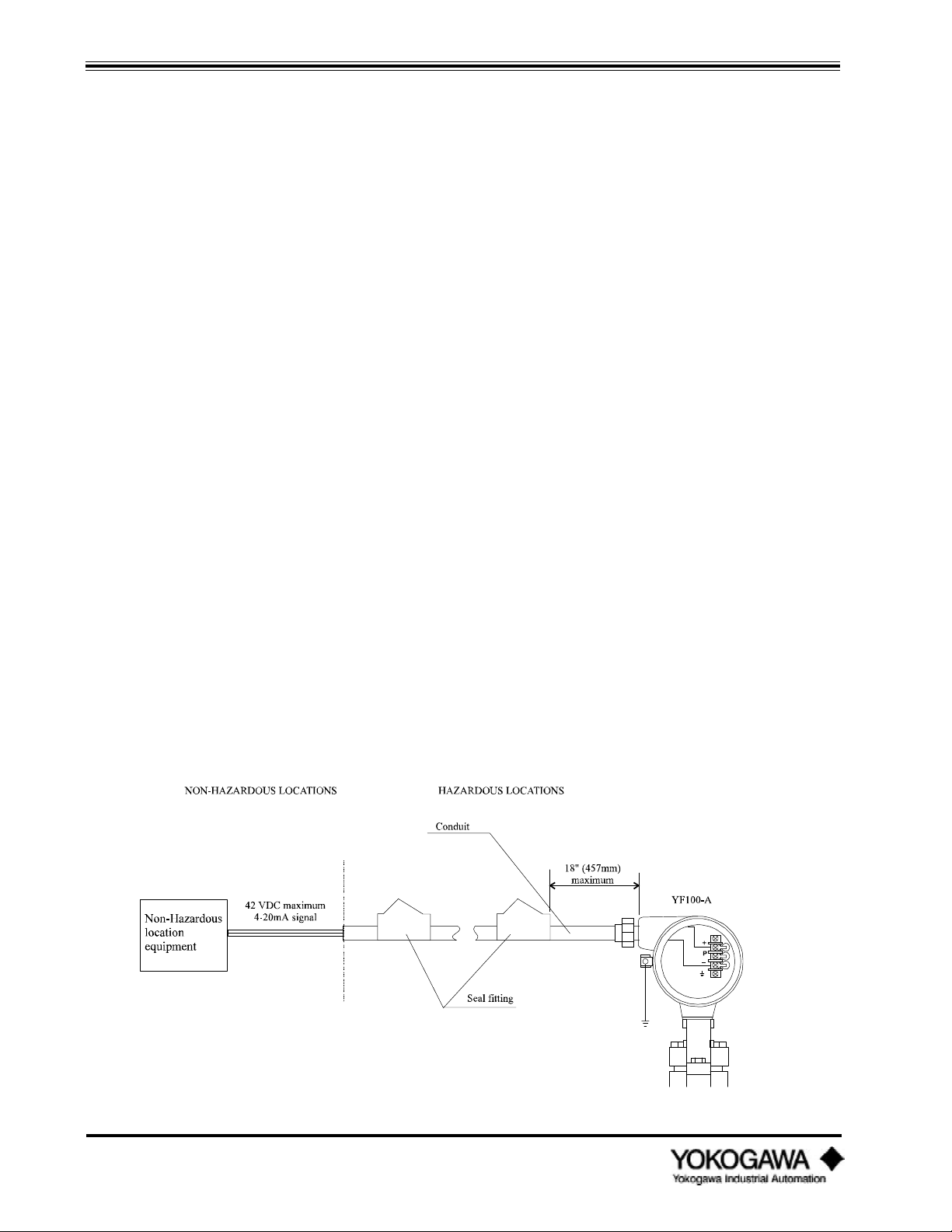
INSTALLATION
2) Connect a plus (+) insulation tester leadwire to these terminals and the minus (–) leadwire to
ground.
3) Turn the insulation tester power ON and measure the resistance between the two leads. Do
not apply the voltage for more than two minutes.
4) After completing the test, disconnect the insulation tester. The short-circuiting wire between
the + and – terminals should be connected to the ground terminal through a 100kΩ resistor
allowing discharge of any internally charged static voltage. Do not make physical contact
with these terminals until the voltage is completely discharged.
• Dielectric Strength Test
1) Short-circuit the + and – (4-20 mA output type) or +, P and – (pulse output type) terminals in
the terminal box.
2) Connect a dielectric strength tester between the + and – terminals and the ground terminal.
(Connect the dielectric strength tester positive (+) leadwire to the short-circuited terminals
and negative (–) leadwire to the transmitter ground terminal.)
3) Gradually increase the test voltage from 0 to the specified voltage.
4) When the test voltage is obtained, maintain it for one minute.
5) After completing this test, slowly decrease the voltage to avoid any voltage surges.
3.5.3 Instruction document for FM explosionproof instruments
Wiring
• All wiring shall comply with the national electrical code ANSI/NFPA70 and local electrical codes.
• In hazardous locations, wiring shall be placed in a conduit.
Operation
• WARNING: Do not open the cover while the circuit is alive.
• Avoid generating mechanical sparks when near the instrument and peripheral devices in hazardous
locations.
Maintenance and Repair
• Instrument modification or replacement parts provided by anyone other than an authorized
representative of Yokogawa Industrial Automation is prohibited and will void the Factory
explosionproof certification.
IM 1F2B4-01-YIA
Page 50
Figure 3.5.1: Integral Type
Page 47
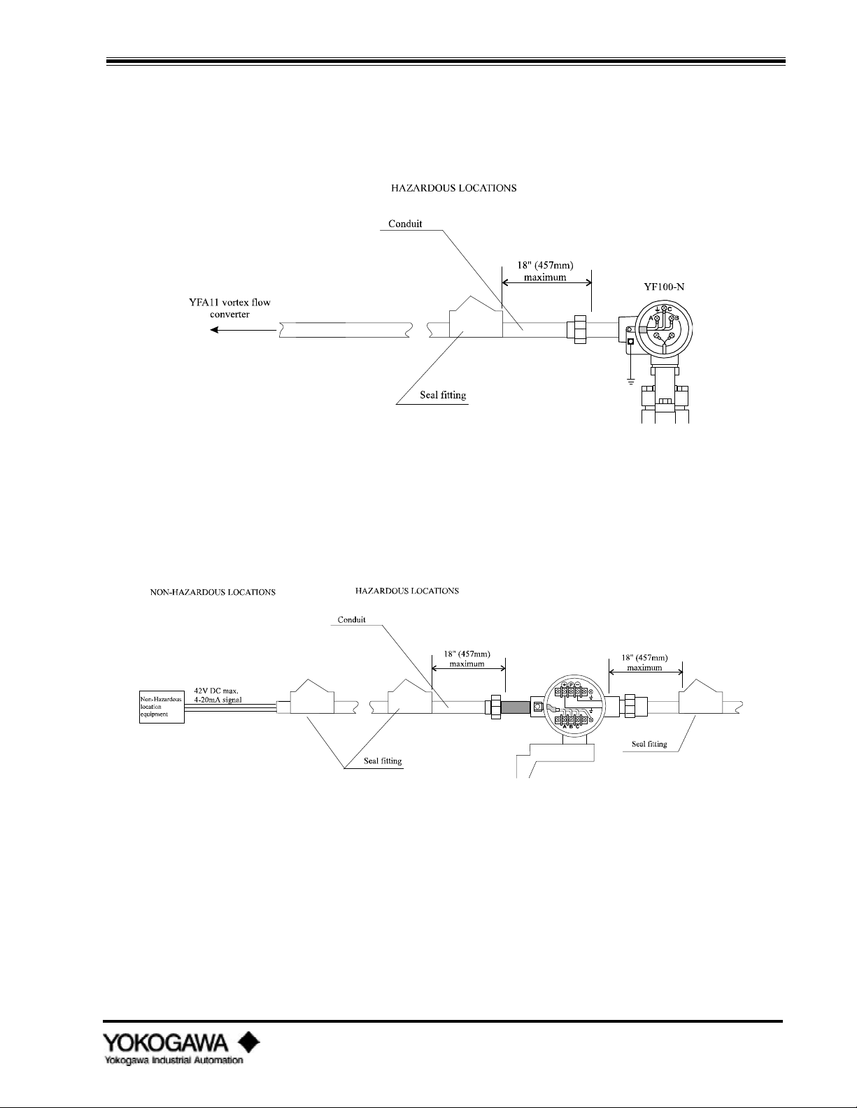
INSTALLATION
(A) YF100-A series Vortex flowmeters can be used in the following hazardous areas:
• Explosionproof for Class I, Division 1, Groups B, C and D.
• Dust ignition-proof for Class II, Division 1, Groups E, F and G
• Suitable for Class III, Division 1
• Outdoor hazardous locations, NEMA 4
Figure 3.5.2: Remote Type
(A) YF100-N series Vortex flowmeters can be used in the following hazardous areas:
• Explosionproof for Class I, Division 1, Groups B, C and D.
• Dust ignition-proof for Class II, Division 1, Groups E, F and G
• Suitable for Class III, Division 1
• Outdoor hazardous locations, NEMA 4
Figure 3.5.3: Remote Converter
(A) YFA11 series Vortex flowmeters can be used in the following hazardous areas:
• Explosionproof for Class I, Division 1, Groups B, C and D.
• Dust ignition-proof for Class II, Division 1, Groups E, F and G
• Suitable for Class III, Division 1
• Outdoor hazardous locations, NEMA 4
IM 1F2B4-01-YIA
Page 51
Page 48

INSTALLATION
3.5.4 Wiring cautions for CSA intrinsic safety
If the meter is to be installed in an intrinsically safe system, safety barriers must be installed to
prevent excessive power from entering the hazardous area.
• Integral Installation
Doc. No. ICS002-A12 p. 1
*CSA certified barrier with parameters of 28V/300 ohms.
IM 1F2B4-01-YIA
Page 52
Page 49

INSTALLATION
• Remote Installation
Doc. No. ICS002-A12 p. 1
*CSA certified barrier with parameters of 28V/300 ohms.
IM 1F2B4-01-YIA
Page 53
Page 50

INSTALLATION
3.5.5 Wiring cautions for FM intrinsic safety
If the meter is to be installed in an FM intrinsically safe system, safety barriers must be installed to
prevent excessive power from entering the hazardous area.
• Non-incendive Integral Installation
'
IM 1F2B4-01-YIA
Page 54
Page 51

INSTALLATION
• Non-incendive Remote Installation
Non-incendive Parameters:
Vmax = 28V, Imax = 93mA, Ci = 4nF (analog output), Ci = 62nF (pulse output), Li = 0
Vmax > Voc, Imax > Isc, Ca > Ci + Ccable, La > Li + Lcable
Notes:
1. Division 2 power source must be FMRC approved.
2. Control room equipment connected to the power supply must not use or generate more than 250V.
3. YF011 Signal Cable max length 131 ft. (40 m).
IM 1F2B4-01-YIA
Page 55
Page 52

INSTALLATION
• Intrinsically Safe Remote Installation
• Intrinsically Safe Integral Installation
IM 1F2B4-01-YIA
Page 56
Page 53

INSTALLATION
• Max. Entity Parameters
Vmax = 28 Vdc
Imax = 93 mA
Pmax = 0.66W
Analog Output
Pulse Output
Ci 4 nF 62 nF
Li 0 mH 0 mH
• Installation Requirements
Vmax > Voc or Vt
Imax > Isc or It
Ca > Ci + Ccable
La < Li + Lcable
Notes:
1. YF011 signal cable max length 20 meters.
2. Maximum non-hazardous location voltage must not exceed 250v.
3. Do not alter drawing without authorization from FMRC.
4. Installation should be in accordance with ANSI/ISA RP12.6. "Installation of Intrinsically Safe
Systems for Hazardous (Classified) Locations" and the National Electrical Code (ANSI/NFPA
70).
5. Approved dust-tight seals are required for Class II and III installations.
IM 1F2B4-01-YIA
Page 57
Page 54

MAINTENANCE
IV. MAINTENANCE
4.1 HOW TO...
The following how to lists are described in this chapter.
4.1.1 Communicating with the YEWFLO remotely
4.1.2 Adjusting zero and span
4.1.3 Using self-diagnostics
4.1.4 Simulating an output/performing a loop check
4.1.5 Changing the output mode to analog or pulse
4.1.6 Increasing gas and steam flow measurement accuracy by correcting for gas expansion
4.1.7 Activating Reynolds number correction
4.1.8 Activating mismatched pipe schedule (bore) correction
4.1.9 Setting up and resetting the internal totalizer
4.1.10 Scaling the pulse output
4.1.11 Setting up user defined flow units
4.1.12 Setting up the local LCD indicator display mode
4.1.13 Setting the low cut flowrate
4.1.14 Trimming the 4-20 mA analog output
4.1.15 Using the upload/download feature
For information on the following items, please refer to the noted reference points.
Adjusting trigger level adjustment (TLA) ................................................ see signal conditioning
Adjusting noise balance ........................................................................... see signal conditioning
Adjusting noise judge............................................................................... see signal conditioning
Connecting an oscilloscope to read the output from the YEWFLO ........... see troubleshooting
Minimizing the affects of noise ................................................................ see signal conditioning
Sizing a YEWFLO .................................................................................. refer to YEWFLO
sizing software
Calculating pressure drop through a flowmeter......................................... refer to YEWFLO
sizing software
Driving an output by inputting a frequency............................................... see amplifier calibration
IM 1F2B4-01-YIA
Page 58
Page 55

MAINTENANCE
4.1.1 Communicating with the YEWFLO remotely
The BT100/BT200 may be connected directly to terminals on the amplifier to communicate. You must
direct connect to communicate when the output jumpers are set for pulse output. With analog output
configuration, you may communicate either on the 4-20 mA loop wires or via a direct connection. The
following conditions must exist in either case for communication to operate properly.
Analog output mode
1. 250Ω to 600Ω of resistance must be in the loop, even for direct amplifier connection.
2. The output jumpers on the amplifier must be set to the analog position.
3. The vortex meter must be powered by 18.5 to 42 VDC. For proper communication at the meter
terminals, the ripple should be < 100 mVAC. Refer to figure 1.3.2 for power supply requirements.
4. Attach one end of the BT100/200 communication cable to the top of the communicator.
5. For Analog mode, there are two ways to communicate as follows:
A. Local Communication: Attach the other end of the communication cable to the HHT ANALOG
terminal and the HHT COM terminal on the amplifier itself. These connection points are labeled
per above and color coded with a yellow bead. Polarity does not matter.
B. Remote Communication: Connect the handheld terminal to the 4-20 mA signal wires, such that
at least 250Ω of the loop load is between the leads. Polarity does not matter.
Pulse output mode
1. The output jumpers on the amplifier must be set to pulse position.
2. The vortex meter must be powered by 14 to 30 VDC.
3. Attach one end of the BT100/200 communication cable to the top of the communicator.
4. On a pulse output vortex meter there is NO requirement for 250Ω of resistance.
5. For Pulse mode, only local communication is supported.
A. Attach the other end of the communication cable to the HHT PULSE terminal and the HHT
COM terminal on the amplifier itself. These connection points are labeled per above and color
coded with a yellow bead. Polarity does not matter.
Communication Start-up
BT200 handheld terminal BT100 handheld terminal
1. Power up by pressing the ON/ OF F key.. Power up by pressing the P O WE R key.
The WELCOME message indicates the handheld terminal is working properly.
2. Press E N T E R and a screen of information such as
YEWFLO*E showing what instrument you are connected
to, TAG NO., and SELF CHECK status, is displayed.
3.
4.
At this point you are ready to begin configuring or otherwise interrogating the YEWFLO parameters.
5.
Pressing E N T E R again (F 4 soft key OK) will
display a list of menus to choose from.
Press ME NU (or any key) and YEWFLO*E is displayed
showing your instrument connection.
Press me n u (or any key) again and TAG NO. is
displayed.
Press me n u (or any key) again to display SELF CHECK
status.
Pressing me n u (or any key) again will take you to
the A:DISPLAY menu - the top of all menus.
This process completes start-up of communication. Once you are successfully communicating, please refer
to the appropriate “How To” section to help you make the configuration change desired. If you receive a
Comm. Er ror recheck the connections as described above, and insure that the batteries in the handheld
terminal are fully charged. Refer to figure 4.5.1 for a connection diagram.
IM 1F2B4-01-YIA
Page 59
Page 56

MAINTENANCE
4.1.2 Adjusting zero and span
Zero Adjustment
There is no zero adjustment required on the YEWFLO. This is a procedure frequently required on other
types of flowmeters but is not applicable to the YEWFLO vortex flowmeter. If the vortex meter provides
an output in a no flow situation refer to the signal processing section or troubleshooting section of this
manual.
Span Adjustment
All YEWFLO vortex meters, both analog and pulse output units, require an initial span setting. If you
provided the correct process conditions at the time of your order, span has been preset at the factory. If it
is necessary to change this value, follow this procedure to make a span adjustment.
BT200 handheld terminal BT100 handheld terminal
B :SET 1
Using the up/down arrows,
scroll to the B :SET 1 menu and
press E N T E R .
Depress the Me n u key until
B :Set 1 menu appears.
B51: SPAN FACTOR
E+1
B52 :FLOW SPAN
7,500
Use the up/down arrow keys to
move through the parameter
list until B51: SPAN FACTOR is
displayed, press E NT E R .
Select the desired SPAN FACTOR from the list. If the span value is
greater than 32,000 an exponential S PAN FACTOR (x 10 multiplier)
must be used. For example, a span value of 75,000; the flow span
(B52) would be set to 7,500 and the SPAN FACTOR would be set to
E+1 (101). 7,500 x 101 = 75,000.
Use the arrow keys to scroll
through the choice list, press
E N T E R twice. Press F 4 ,
OK.
Use the arrow key to move to
B52 :FLOW SPAN . Press
E N T E R .
Input the flow span using the numeric keys
Press E N T E R twice. Press
F 4 , OK.
Using the p r mt r key move
through the parameter listing
until B51 :Span Factor appears.
Use the I NC or D E C key to
move through the choice list,
press E N T twice.
Press the P R MT R key once
to move to parameter B52 : FLOW
SPAN
Press E N T twice.
IM 1F2B4-01-YIA
Page 60
Page 57

MAINTENANCE
4.1.3 Using self-diagnostics
From any menu you have access to the self-diagnostics in the YEWFLO.
BT200 handheld terminal BT100 handheld terminal
X60 :Self CHECK
GOOD
From the menu screen, select any menu and
press E NT E R , to enter parameter display
mode. Press F 2 , the DI AG soft key. You may
also scroll down to the “ 60” parameter in the
current menu.
Press the DI AG key and you will
immediately run diagnostics, and the display
will show X60:SELF CHECK with either a GOOD
or ERROR display. Note X denotes the
alphabetic value of the current menu.
If error is displayed, press the E NT E R
key to display an alphanumeric list of the
error or errors. Scroll down to be sure all
error messages are seen. Press F 4 (ESC)
function to return to the menu screen.
As you resolve each condition that is causing an error, the error will automatically be cleared.
To confirm that all errors have been corrected, please perform Step 1 again.
If error is displayed, press I NC or D E C
to view the alphanumeric description of the
error. Continue pressing the I NC or DE C
key to scroll through the error list if there is
more than one.
Refer to the error code listing chart for a detailed description of each error message.
IM 1F2B4-01-YIA
Page 61
Page 58

MAINTENANCE
4.1.4 Simulating an output/performing a loop check
The YEWFLO provides the flexibility to simulate an output to perform a loop test. This feature can be
used for Analog output or Pulse output configurations.
Analog Output - simulate output (parameter B02:OUTPUT must be set to 4-20 mA DC)
BT200 handheld terminal BT100 handheld terminal
F :TEST
From the menu screen scroll down to the
F: TEST choice. Press E NT E R .
Depress the me n u until the F: TEST menu
is displayed.
F01: OUT ANALOG
50
Select F01: OUT ANALOG parameter. Press
E NT E R .
Using the numeric keys, enter the value of percent of span you wish to simulate. i.e. 50%
Press E NT E R twice. Press the E N T twice.
The current output, and the percent of rate display will agree with the value entered in
parameter F01. However, the engineering units display and totalization will continue to read
and totalize the actual flowrate.
Note: Two methods cause the simulated output to return to normal flow reading.
1)
Press the F 4 (ESC) function key.
2) After 10 minutes the output will automatically return to normal.
Press the p r mt r once to display
parameter F01: OUT ANALOG.
Move to any other menu or parameter, by
pushing the ME N U or P RMT R key.
Pulse Output - simulate output (Parameter B02:OUTP UT must be set to PULSE)
BT200 handheld terminal BT100 handheld terminal
F :TEST
F01: OUT pulse
2000
From the menu screen scroll down to the
F:TEST choice. Press E N T E R .
Scroll down to parameter F02: OUT PULSE.
Press E NT E R .
Use the numeric keys, enter the frequency value in Hertz you wish to simulate. i.e. 2000 Hz.
Press E NT E R twice. Press the E N T twice.
The frequency output will respond to the value entered. Note: The pulse output, will agree
with the value entered in parameter F01. However, the percent of span display, engineering
units display and totalization will continue to read the actual flowrate.
Depress the menu key until the F:Test menu
is displayed.
Press the p r mt r twice to display F02:
Out Puls e.
IM 1F2B4-01-YIA
Page 62
Two methods cause the simulated output to return to normal flow reading.
1)
Press the F 4 (ESC) function key.
2) After 10 minutes, the output will automatically return to normal.
Push the Me n u or P R MT R key to move
to another menu or parameter.
Page 59

MAINTENANCE
4.1.5 Changing th e output mode to analog or pulse
Changing the output to Analog output
On the amplifier, move the 3 individual output jumpers to the “ analog” position, these are the 3 pins on
the right as you look at the amplifier board. Refer to figure 1.3.2 for power supply requirements. This step
must be completed before proceeding. NOTE: To communicate in analog output mode you must have a
current loop load of 250Ω 600Ω.
After connecting the communication cable to the BT100/200 connect the clip leads on the other end to the
HHT ANALOG and HHT COM terminals of the amplifier, or on the 4-20 mA signal wires. Power up the
BT100/200 and proceed with the following steps:
BT200 handheld terminal BT100 handheld terminal
B: S ET 1
From the menu screen, select B: SET 1
using the up/down arrows, scroll to and
press the E NT E R key.
Press the ME N U key until the B: S e t 1
menu is displayed.
B02: OUTPUT
4 to 20 mA DC
Changing the output to Pulse output
On the amplifier move the 3 individual output jumpers to the “ pulse” position, these are the 3 pins on the
left as you look at the amplifier board. Refer to figure 1.3.2 for power supply requirements. This step must
be completed before proceeding. NOTE: You cannot communicate remotely in the pulse output mode.
After connecting the communication cable to the BT100/200 connect each alligator clip to the HHT pulse
and HHT COM terminals of the amplifier. Turn the power on the BT100/200 and proceed with the
following steps.
B: S ET 1
B02: OUTPUT
P ULSE
Using up/down keys select B02: OUTPUT
and press the E N T E R key.
Using the up/down arrows, select 4 to 20
mA DC and press the E N T E R key twice.
Then press F 4 , OK.
BT200 handheld terminal BT100 handheld terminal
From menu screen, use the arrow keys to
select B: S ET 1 and press the E NT E R
key.
Use up/down arrows keys to scroll to
B02: OUTPUT. Press E NT E R .
Use the arrow keys to select P ULSE and
press E N T E R twice. Then, press F 4 ,
OK.
Press the p a r a me t e r key until
parameter B02 : Out put is displayed.
Using the I N C and DE C key display
the available options. When 4 to 20 mA
DC is displayed press the E NT key
twice.
Press the ME N U key until the B: S e t 1
menu is displayed.
Press the P R MT R key until parameter
B02: Out put is displayed.
Use the I NC or D E C key to select
P ulse and press the E N T key twice.
IM 1F2B4-01-YIA
Page 63
Page 60

MAINTENANCE
4.1.6 Increasing gas and steam flow measurement accuracy by correcting for gas expansion
To achieve the highest level of performance from a vortex meter when measuring a compressible fluid,
YEWFLO offers a gas expansion factor which will automatically make the necessary correction and
improve gas accuracy to ±0.8% of rate over the full operating range. Without the gas expansion factor, the
standard accuracy is 1.5% of rate.
The pressure drop across the shedder bar increases with increasing flowrate. As the pressure drop
increases, the gas expands. Gas expansion due to the higher pressure drop will cause the vortex flowmeter
to read high. To compensate for this velocity activate the D06: EXPANSION FA parameter. To activate this
function, please follow the steps below:
NOTE: Do not activate this function for liquid flow applications. Review the setting of parameter B04:
FLUI D to confirm the settings are for Gas or Steam only.
BT200 handheld terminal BT100 handheld terminal
D :ADJUST
Proceed to the menu screen
and select the D: ADJUST and
press E N T E R .
Press the ME N U key to move
to the D: Adj ust menu.
D06 :EXPANSION FA
ACTIVE
Scroll through the parameters
to D06 : EXPANSION FA and press
E N T E R .
Using the arrow keys, select
ACTI VE and press E NT E R
twice. Then, press F 4 , OK.
Using the P R MT R key
move to parameter D06
:Ex pansion FA.
To activate this feature use the
I NC or D E C key to select
activ e and press E NT twice.
IM 1F2B4-01-YIA
Page 64
Page 61

MAINTENANCE
4.1.7 Activating Reynolds number correction
What is Reynolds Number Correction?
The YEWFLO vortex meter’ s output is linear beginning at 20,000 Reynolds number, or 40,000 for sizes 6
inch and above. From 5,000 to 20,000 Reynolds number the meter’ s output is nonlinear, but repeatable.
Reynolds number adjustment is a correction factor applied to the output to compensate for this nonlinearity within this Reynolds number range. When activated, flowmeter accuracy is improved to 0.8% of
rate throughout the flow range above 5000 Reynolds number. The correction factors listed below are
automatically applied when this feature is activated.
BT200 handheld terminal BT100 handheld terminal
D: adjust Select the D: adjust menu
and press e n t e r .
Press Me n u until the
D: Adjust menu appears.
D01: Reynolds adj
Active
D02: viscosity
1.0
D03 :Density F
8.3
The flowmeter will now be corrected for flowrates between 5,000 and 20,000 Reynolds number. Please be
sure to input accurate viscosity and density values, as this correction is only as valid as the accuracy of
these parameters. If viscosity and density change, accuracy will be affected until the new values are input.
Scroll to the first parameter,
D01: Reynolds adj, press
e n t e r .
Scroll to the active selection
and press e n t e r twice.
Press F 4 {E S C} to return
to the parameter list.
Select parameter D02:
vi scosity and press
e n t e r .
Input the flowing viscosity in centipoise
Press enter twice, Press f 4
{e s c } to return to the
parameter list.
Scroll to parameter
D03: DENSITY F and press
e n t e r .
Input the flowing density in units per B07 .
Press E N T E R twice. Press e n t twice.
Depress the P RMT R key
and move to the first
parameter D01: Reynolds Adj.
Using I NC or D E C select
acti ve and press e n t twice.
Press P RMT R to move to
D02: viscosity.
Press e n t twice.
Using the parameter key move
to the D03: DENSITY F
parameter.
Note: There are certain conditions where performance in the range of 5,000 to 20,000 Reynolds
number is not possible. Please consult the YEWFLO sizing program, your local representative or the
Yokogawa Industrial Automation factory for clarification.
Reynolds #
Correction
40,000 20,000 12,000 8,000 5,500
0% -1.0% -3.6% -6.5% -11.4%
IM 1F2B4-01-YIA
Page 65
Page 62

MAINTENANCE
4.1.8 Activating mis-matched pipe schedule (bore) correction
The mating pipe in a vortex meter installation should be schedule 40 pipe, using other schedule pipes can
cause small errors. If a pipe schedule other than schedule 40 is being used the error can be corrected using
the pipe effect correction.
Mis-matched pipe schedule correction
BT200 handheld terminal BT100 handheld terminal
D: adjust
Select menu D: adj ust and
press e n t e r .
Press me n u until d: adj ust
is displayed.
d05: pipe effect
Wafer Sch80
Pipe schedule correction is now invoked, and accuracy will be corrected for the combination selected.
Model Size Wafer Flange
YF101 ½” (15 mm) 0 -0.8 0 0.1
YF102 1” (25 mm) 0
YF104 1½” (40 mm) -0.2
YF105 2” (50 mm) 0.1 -0.9 0
YF108 3” (80 mm) 0.2 0.2 0.1
YF110 4” (100 mm) 0.2 -0.1 0.1 0
YF115 6” (150 mm) NA NA NA 0.3 -0.1
YF120 8” (200 mm) NA NA NA 0.3 -0.1
YF125 10” (250 mm) NA NA NA 0 0
YF130 12” (300 mm) NA NA NA 0 0
Scroll to the d05 : pipe effect
parameter and press
e n t e r .
Select from the list the correct
combination of process
connection (wafer or flange)
and pipe schedule, (Sch10,
Sch80 etc.), and press
e n t e r twice.
Sch 10
(%)
Sch 40 Sch 80
No
Correction
(%)
-0.7 0 0.1
-0.3 0 0.1
Press the p r mt r key until
the D05 : pipe effect menu
appears.
Using the i n c or d e c
keys, select the correct
combination of process
connection and pipe schedule,
press e n t twice.
Sch 10
(%)
Sch 40 Sch 80
No
Correction
(%)
0.1
0
IM 1F2B4-01-YIA
Page 66
Page 63

MAINTENANCE
4.1.9 Setting up and resetting the internal totalizer
Setup of the internal totalizer
BT200 handheld terminal BT100 handheld terminal
C: SET 2
Scroll through the menus to the C: SET 2 ,
then press E N T E R .
Press the ME N U key until the C: Set 2
menu appears.
C01: Total Rate
Note: When factors other than E0 are used the appropriate multiplier sticker should be placed on the
bezel of the local indicator, if present (/TBL).
Scroll down to C01: Tot al Rat e and press
E N T E R .
Scroll to the desired totalizer factor, press
E N T E R twice.
The available options for totalizer rates include scaled and unscaled rates
Examples:
E 0
E +2
E -2
There are three special settings designed to maximize resolution:
UNSC * 1
UNSC * 10
UNSC * 100
Note: Set this parameter such that the maximum count or pulse rate does not exceed
6,000 Hz.
Press p r mt r key to move to
parameter C01: Total Rate.
Use the I NC or D E C key to select the
desire totalizer factor. Press E NT twice.
1 count equals one unit of flow (100) ,
units same as flow unit.
1 count equals 100 units of flow (102) ,
units same as flow unit.
1 count equals 0.01 units of flow (10-2) ,
units same as flow unit.
1 pulse in, 1 count out (Unscaled)
1 pulse in, 10 counts out (Unscaled)
1 pulse in, 100 counts out (Unscaled)
Resetting the internal totalizer
BT200 handheld terminal BT100 handheld terminal
E: CONTROL
E01: TOTAL RESET
execute
Note: This parameter will automatically revert to NOT EXECUTE, when you exit the parameter.
Scroll to the E: CONTROL menu and press
E N T E R .
Scroll to parameter E01: TOTAL RESET and
press E N T E R .
Scroll to the value Exec ute and press
e n t e r twice to reset the totalizer.
Press the ME N U key until the E:
Control menu appears.
Press the P R MT R key once to display
the parameter E01: Total Reset.
Use the I NC or D E C key to select
ex ecute and press e n t twice to reset
the totalizer.
IM 1F2B4-01-YIA
Page 67
Page 64

MAINTENANCE
4.1.10 Scaling the pulse output
Before setting the pulse rate be sure that the YEWFLO has been properly set to pulse output mode. The
pulse output of the YEWFLO may be configured as a scaled or unscaled pulse output. Follow this
procedure to set the pulse scaling. Use scaled pulse to scale the output to pulses per engineering unit per
B51 Flow span units. Use unscaled pulse (UNSC*1, UNSC*10 or UNSC*100) for maximum pulse
resolution. Output will be 1, 10 or 100 pulses output for each input pulse. Use the K-factor to convert
unscaled units to volume units.
Setup of pulse output
BT200 handheld terminal BT100 handheld terminal
C: SET 2
Scroll through the menus to the
C: SET 2, then press E NT E R.
Depress the ME NU key until
the C: Set 2 menu appears.
C02: pulse rate
E +2
Scroll down to C02: p ulse r ate
and press E NT E R.
Select from the list the desired
pulse rate factor, press
E N T E R twice.
The available options for pulse rate include scaled and unscaled
rates.
Examples:
E 0
E +2
E - 2
There are three special unscaled settings designed to maximize
resolution:
UNSC * 1
UNSC * 10
UNSC * 100
Press p r mt r key to move
to parameter C02: pulse r ate .
Use the I NC or D E C key to
select the desire pulse rate
factor. Press E N T twice.
1 pulse equals one unit of flow
(100), units same as flow span.
1 pulse equals 100 units of
flow (102), units same as flow
span.
1 pulse equals 0.01 units of
flow (10-2), units same as flow
span.
1 pulse in, 1 pulse out
(Unscaled)
1 pulse in, 10 pulses out
(Unscaled)
1 pulse in, 100 pulses out
(Unscaled)
Set this parameter such that the maximum count or pulse rate does not exceed 6,000 Hz at max flow span.
Note: Gas Expansion Correction Factor in % reading = (-5.70833 x E-4 x V2) - (5.83333 x E-4 x V);
IM 1F2B4-01-YIA
Page 68
Where V = Average measured uncorrected velocity in m/sec
Page 65

MAINTENANCE
4.1.11 Setting up user defined flow units
It is possible that the flow units required for a particular application may not be available as standard flow
units. Therefore, YEWFLO offers the flexibility of setting custom user units for any application.
BT200 handheld terminal BT100 handheld terminal
B :SET 1
B35 :Fl ow unit
USGAL
B50 :Time Unit
/ m
C: SET 2
Scroll to the B: SET 1 menu and press the
E N T E R key. Select a standard flow
unit for parameters B15, B22, B29, or B35
and select a standard time base for
parameter B50 from the available list.
Make your selection from the list by
scrolling to it and pressing E N T E R
twice.
Only one of the above flow unit parameters will be available depending on whether
your application is for Gas, Liquid, Steam or Energy flow as selected in B04 :Fl uid.
From the menu screen scroll down to
C: SET 2 and press E N T E R. Then,
press F 4 , OK.
Using the me n u key move to the
B: SET 1 menu. Using the P RMT R key,
select parameters B15, B22, B29, or B35.
Then using the I NC or D E C key,
select a standard unit. Use the P RMT R
key to select parameter B50 and I NC or
DE C to select a standard time base.
Press the ME N U key until C: Set 2 is
displayed.
C09: UNIT CONV FA
0.0238
C10: USERS UNIT
BBL
The C09: Unit Conversion Fa is defined as: Standard Units/Custom Unit
Example: Set up for span of 50 BBL/h (Barrels per hour)
B35: FLOW UNIT..................USgal; conversion = 42 USgal/BBL (oil) or .0238 BBL/USgal
B50: TIME UNIT.................../h
C09: Unit Conversion Fa ..Enter 0.0238 BBL/USgal
C10: USER’ S UNIT .............Enter the abbreviation for barrels; BBL
After making the above modifications, the units of flow will now be barrels per hour, BBL/ h. This unit will
not appear on the /TBL indicator, but only when communicating with the BT100 or BT200. Parameter
A20 will now indicate flowrate in BBL/ h and parameter A30 will now totalize in Barrels, BBL.
NOTE: After making these settings, the value of parameter B52: FLOW S PAN must be set in custom user
units, i.e. BBL/ H or 50, for this example.
Scroll down to C09: UNIT CONV FA and
press E N T E R . Using the numeric
keys, enter the conversion factor and
press the E NT E R key twice. Press
F 4 , OK.
See below for how to calculate the correct conversion factor.
Scroll to parameter C10: USERS UNIT and
press the E NT E R key. Enter the
custom flow units abbreviation using the
alphanumeric keys. Press E N T E R
twice to save.
Using the P R MT R key move through
this menu until parameter C09: Unit
Conversion Fa is displayed. Use the
numeric keys, enter the conversion factor
and press the E N T key twice.
Using the P R MT R key move to the
c10: users unit parameter and enter the
custom flow units abbreviation using the
alphanumeric keys. Press E N T twice to
save.
Setting parameter C09: Uni t Conversion Fa to any value other than ‘ 0’ activates the custom user units
function. To clear this function set C09 to ‘ 0’ .
IM 1F2B4-01-YIA
Page 69
Page 66

MAINTENANCE
4.1.12 Setting up the local LCD indicator display mode
The YEWFLO vortex meter offers a variety of display options. The following procedure will allow you to
select which values are displayed, for your application.
BT200 handheld terminal BT100 handheld terminal
E: CONTROL
Scroll through the menus to
the E: CONTROL menu, then
press E N T E R .
Press the ME N U key until
the E: Contr ol menu is
displayed.
E02: DISP SELECT
rate %
Scroll to parameter E02: DISP
SELECT then press E NT E R.
Scroll to your desired choice,
press E N T E R twice.
Select one of the 6 display options for the local indicator.
The available options are:
rate %
rate
tot al
rate%, total
rate, total
rate, rat e%
Using the p r mt r key
move to parameter E02: Disp
Select .
Using I NC or D E C move
to the display option of your
choice, press E NT twice to
select.
Rate in percent of span.
Rate in engineering units.
Totalized flow in engineering
units.
Alternating display; rate in
percent of span and total flow.
Alternating display; rate in
engineering units total flow.
Alternating display; rate in
engineering units and rate in
percent of span.
IM 1F2B4-01-YIA
Page 70
Page 67

MAINTENANCE
4.1.13 Setting the low cut flowrate
The low cut flowrate is a digital cut-off that can be configured to force the analog or pulse output to 0%
when the flow is below a predetermined value. This parameter is used especially to lock out erroneous
flow signals that may occur below Qmin, where it may be desirable to have the meter drop to zero rather
than provide erroneous readings.
To set the low cut flowrate; move to menu H: Maintenance , then move down to H07: L.C. Flowr at e . Using
the numeric keypad input the low flow cut-off flowrate in flow span units. Once this value is stored, any
signal below the low cut flowrate will generate a 0% output.
H :Maintenance
H07 :L.C. Flowrate
10
BT200 handheld terminal BT100 handheld terminal
Move to parameter H07, input the desired low flow cut-off value in flow span units,
i.e. 10 Gal/min.
Press E n t e r twice. Press e n t twice.
IM 1F2B4-01-YIA
Page 71
Page 68

MAINTENANCE
4.1.14 Trimming the 4-20 mA analog output
The 4-20 mA analog output circuit is accurately calibrated at the factory using precision test equipment.
Field adjustment of this circuit is rarely required. This adjustment should not be made when there is a
suspected offset of the 4 mA point due to noise such as pipe line vibration, in this case, please refer to
signal conditioning.
If you find it necessary to trim the 4 mA and/or 20 mA value, it can be adjusted digitally with the
handheld terminal. An example of when to use this adjustment would be when there is a 250Ω resistor in
the loop changing the output to 1 - 5 volts. If the resistor value is not exact, an offset error of either the 4
mA (1V) and/or 20 mA (5V) reading will occur.
To digitally trim the current output, refer to the following formula and example to determine the correct
digital trim parameter settings. The parameter H08 : Tri m 4mA is used to adjust the 4 mA (or 0%) output,
and parameter H09 :Trim 20mA is used to adjust the 20 mA (or 100%)
H :Maintenance
H08 :TRIM 4ma
0.45 %
H09 :Trim 20ma
1.25 %
H08 :TRIM 4ma
0.8993 %
BT200 handheld terminal BT100 handheld terminal
Move to parameter H08, re-enter the
value shown, (.45 this example) press
E n t e r twice. The output will go to
0%. (Don’ t press OK until you are ready
to leave this parameter).
Read the analog output at 0% and record it as X (3.93mA this example).
Record the original value of H08 (0.45 this example).
Move to parameter H09 and re-enter the
value shown, (1.25 this example) press
e n t e r twice. The output will go to
100%. (Don’ t press OK until you are
ready to leave this parameter).
Read the analog output at 100% and record it as Y (19.72mA this example).
Record the original value of H09 (1.25 this example).
Calculate the New H08 setting using X and Y from above in Equation 1.
Calculate the New H09 setting using X and Y from above in Equation 2.
Store the New H08 setting (confirm the output goes to 4 mA or 0%).
Move to parameter H08 and press e n t
twice.
Move to parameter H09 : TRIM 20ma and
press e n t twice.
H09 :Trim 20ma
2.58%
IM 1F2B4-01-YIA
Page 72
Store the New H09 setting (confirm the output goes to 20 mA or 100%).
Page 69

MAINTENANCE
milliAmp example:
Calculate the new settings using X and Y values from above:
(Equation 1)
NEW H08 setting = ( 4 - X ) / ( Y - X ) * 100 + orig. H08 setting
example: 0.89 = ( 4 - 3.93 )/( 19.72 - 3.93 ) * 100 + 0.45
Example: milliAmp
Original New
H08
H09
X
Y
(Equation 2)
NEW H09 setting = ( 16 + X - Y )/( Y - X )*100 + current H09 setting
example: 2.58 = ( 16 + 3.93 - 19.72 )/( 19.72 - 3.93 ) * 100 + 1.25
.45 .89
1.25 2.58
3.93 mA 4.00 mA
19.72 mA 20.00 mA
0-100% example:
Calculate the new settings using X and Y values from above, where X and Y have been converted
to % of span values.
Example: 0-100%
Original New
H08 .45 .89
H09 1.25 2.58
X -0.43% 0.0%
Y 98.25% 100.0%
(Equation 1)
NEW H08 setting = - X / ( Y - X ) * 100 + orig. H08 setting
example: 0.89 = - ( -0.43 )/( 98.25 - (-0.43)) * 100 + 0.45
(Equation 2)
NEW H09 setting = ( 100 + X - Y )/( Y - X )*100 + current H09 setting
example: 2.58 = ( 100 + (-0.43) - 98.25 )/( 98.25-(-0.43)) * 100 + 1.25
IM 1F2B4-01-YIA
Page 73
Page 70

MAINTENANCE
4.1.15 Using the upload/download feature
The upload/download feature of the BT100/200 allows for one meter to be configured for an application
and then be copied to other meters with a minimum of key strokes. Note: Only the parameters in menu B
and C will be transferred via the upload/download procedure. The tag number will not be transferred.
To UPLOAD a configuration:
BT200 handheld terminal BT100 handheld terminal
1. Attach the handheld terminal leads to the appropriate
instrument.
2. Using the BT100/200 set up the parameters in the YEWFLO as
required, or go to step 3 if the YEWFLO is already setup.
3. From the menu screen, press
F 4 , (E S C ) soft key to go to
the Function menu. Scroll
down and select the UPLOAD TO
HHT choice.
4. Press E NT E R twice to
begin the upload.
5.
Do not disconnect the leads until the UPLOAD DONE or upload
COMPLETE message is displayed. Note: Only one configuration at
a time may be stored in either the BT100 or BT200.
From any menu or parameter
display, press the UP L D
key.
Press the E NT twice to begin
the upload.
To DOWNLOAD a stored configuration:
BT200 handheld terminal BT100 handheld terminal
1. Attach the handheld terminal leads to the appropriate
instrument.
2. From the menu screen, press
F 4 , (ESC) soft key to go to
the Function menu. Scroll
down and select the DOWNLOAD
TO I NST choice.
Press E N T E R twice to
begin the download.
3.
Do not disconnect the leads until the Download DONE or
DOWNLOAD COMP LETE message is displayed. Note: This same
configuration may be downloaded to as many YEWFLO meters
as are required.
Note: Only the parameters in menu B and C will be transferred via the upload/download procedure. The
tag number will not be transferred.
From any menu or parameter
display, press the DN L D
key.
Press E N T twice to begin the
download.
IM 1F2B4-01-YIA
Page 74
Page 71

MAINTENANCE
4.2 DISASSEMBLY AND REASSEMBLY
This section describes disassembly and reassembly procedures required for maintenance and parts
replacement. For replacement parts, see the parts list at the end of this manual.
Before disassembling the transmitter, turn the power off and release the pressure. Be sure to use the
proper tools for disassembling and reassembling.
Caution: It is prohibited by law for the user to modify flameproof instruments. This includes adding or
removing indicators. If modification is required, contact Yokogawa Industrial Automation.
4.2.1 Indicator/Totalizer removal
When servicing the amplifier, follow procedures below.
1) Turn the power off.
2) Remove the cover.
3) Completely loosen the four indicator mounting screws using a Phillips head screwdriver.
4) Disconnect the cable connector from the amplifier unit .
5) Pull out the indicator.
6) To reinstall the indicator, follow these steps in reverse order (step 5 to step 1).
7) The ribbon cable key located on top of the connector should face upward when installed.
4.2.2 Amplifier replacement
Replace the amplifier as follows:
1) Turn the power off.
2) Remove the converter cover.
3) If required, remove the indicator as described in section 4.2.1.
4) Slightly loosen the three (3) terminal screws and remove the leadwires from the P, + and -
Figure 4.2.1: Removing and reinstalling the indicator
terminals. Don't drop the screws.
IM 1F2B4-01-YIA
Page 75
Page 72

MAINTENANCE
5) Completely loosen the three amplifier mounting screws and remove the amplifier as shown
in figure 4.2.1.
Caution: To avoid damaging the connector pins, do not rotate the amplifier unit.
6) When reinstalling the amplifier in the converter, match the connector pin positions with the
socket then gently push the amplifier back into position. Don't push too hard or you will
bend the pins.
7) Tighten the amplifier mounting screws.
8) Reconnect the leadwires to the amplifier. The sensor wires must be connected to the proper
terminals for the amplifier to work correctly.
9) Set flowmeter parameters in the new amplifier.
4.3 VORTEX SHEDDER ASSEMBLY REMOVAL
Disassemble the vortex flowmeter only if the it performs abnormally. First determine the problem. Is
buildup causing problems in the assembly or is it bad. You can check for buildup when you remove
the shedder from the meter. If it slides out freely, buildup is not the problem. If it sticks, you should
clean around the bottom socket and edges to remove residue. The following steps detail removal and
reassembly procedures.
4.3.1 Removal of shedder from remote converter type
1) Remove the terminal box cover.
2) Loosen the two terminal screws and disconnect the sensor
Terminal Wire
P Black
+ Red
- White
wires (A & B).
3) Remove the bracket mounting bolts and remove the terminal box and bracket
simultaneously. Carefully remove the terminal box by first straightening the sensor wires. To
avoid damaging the wires, squeeze the wires as you slide the terminal out.
4) Remove the vortex shedder assembly mounting bolts then remove the assembly. Check for
buildup around the shedder bar holes and inside the meter.
5) When reassembling the vortex shedder bar assembly, reverse the above procedure making
sure the arrow on the plate is aligned with the flow on the meter body.
Color Wire
Red A
White B
Table 4.3.1: Sensor Wire Color Code
IM 1F2B4-01-YIA
Page 76
Page 73

MAINTENANCE
Figure 4.3.1: Disassembling and Reassembling the Vortex Shedder Assembly
Caution: When the shedder assembly is disassembled, the gasket must be replaced with a new gasket.
4.3.2 Removal of the shedder from integral type
1) Remove the converter cover.
2) Remove the amplifier. Refer to section 4.2.2 for directions.
3) Loosen the two terminal screws to disconnect sensor wires (A & B).
4) Remove the bracket mounting bolts and remove the terminal box and bracket
simultaneously. Carefully remove the terminal box by first straightening the sensor wires. To
avoid damaging the wires, squeeze the wires as you slide the terminal out.
5) Remove the vortex shedder assembly mounting bolts then remove the assembly. Check for
buildup around the shedder bar holes and inside the meter.
6) When reassembling the vortex shedder bar assembly, reverse the above procedure making
sure the arrow on the plate is aligned with the flow on the meter body.
IM 1F2B4-01-YIA
Page 77
Page 74

MAINTENANCE
Figure 4.3.2: Disassembling and Reassembling the Vortex Shedder Assembly
4.4 RE ASSEMBLY CAUTIONS
1) Use a new gasket.
2) Orient the shedder bar with the wider surface upstream. Align the guide pin on the vortex
shedder mounting block with the guide pin hole (1" - 4" flowmeters only). See figure 4.4.1.
3) Install the vortex shedder assembly properly.
4) Tighten all mounting bolts with a torque wrench. Use table 4.4.1 to determine the correct
torque value.
IM 1F2B4-01-YIA
Page 78
Page 75

MAINTENANCE
Figure 4.4.1: Vortex Shedder Bar Orientation
For high temperature assemblies (option /HPT), first tighten the bolts with a torque wrench applying
the A value. Next, completely loosen all the bolts and retighten with a torque wrench this time using
the B value.
5) Insert the sensor wires through the bottom hole of the terminal box. Slowly lower the
terminal box until the bracket touches the flowmeter shoulder. Be sure to keep the sensor
wires vertical while lowering the terminal box.
6) After assembly, confirm that there is no leakage.
4.4.1 YEWFLO shedder bolt torque procedure
Table 4.4.1 summarizes the torque values which should be used when reinstalling a shedder bar in
any YEWFLO Vortex meter. When reading this table, please keep the following in mind:
1) Use the TEFLON COATED GASKET table for all meters with teflon-coated gaskets.
2) Use the SILVER PLATED GASKET tables for all meters with silver-coated gaskets
regardless of whether they have a high-temperature sensor.
3) For meters with four bolts, tighten alternate bolts to produce an even compression of the
gasket.
4) Enter the appropriate table using the meter size. Tighten all bolts to the value shown in the
first column. When finished, tighten all bolts to the value shown in the second column.
Continue this procedure until all bolts are tightened to the highest torque value.
5) For meters with silver-coated gaskets, begin by using the table labeled 1st round. When
complete, unscrew all attachment bolts until the gasket compression plate is loose. Retighten
all bolts using the values shown in the table marked 2nd round. Notice that some torque
values are less for the second tightening sequence than for the first.
IM 1F2B4-01-YIA
Page 79
Page 76

MAINTENANCE
BOLT TORQUE CHART
GREEN TEFLON COATED GASKET TORQUE
Size 1st 2nd 3rd 4th 5th
YF101 40 in-lb 70 in-lb 100 in-lb 140 in-lb
YF102,104 25 in-lb 60 in-lb 90 in-lb 105 in-lb
YF105 10 ft-lb 15 ft-lb 22 ft-lb 29 ft-lb
YF108 10 ft-lb 22 ft-lb 37 ft-lb 43.5 ft-lb
YF110 10 ft-lb 22 ft-lb 43.5 ft-lb 58 ft-lb 72.5 ft-lb
YF115 10 ft-lb 15 ft-lb 29 ft-lb 36.5 ft-lb
YF120 10 ft-lb 22 ft-lb 37 ft-lb 51 ft-lb
SILVER PLATED GASKET 1ST ROUND
Size 1st 2nd 3rd 4th 5th
YF102,104 30 in-lb 60 in-lb 90 in-lb 120 in-lb 152 in-lb
YF105 10 ft-lb 22 ft-lb 37 ft-lb 43.5 ft-lb
YF108 10 ft-lb 22 ft-lb 43.5 ft-lb 58.5 ft-lb 72.5 ft-lb
YF110 20 ft-lb 40 ft-lb 60 ft-lb 80 ft-lb 101 ft-lb
YF115 10 ft-lb 15 ft-lb 29 ft-lb 36.5 ft-lb 51 ft-lb
YF120 10 ft-lb 22 ft-lb 37 ft-lb 51 ft-lb 72 ft-lb
SILVER PLATED GASKET 2ND ROUND
Size 1st 2nd 3rd 4th 5th
YF102,104 30 in-lb 60 in-lb 90 in-lb 105 in-lb
YF105 10 ft-lb 15 ft-lb 22 ft-lb 29 ft-lb
YF108 10 ft-lb 22 ft-lb 37 ft-lb 43.5 ft-lb
YF110 20 ft-lb 22 ft-lb 43 ft-lb 58 ft-lb 72.5 ft-lb
YF115 10 ft-lb 15 ft-lb 29 ft-lb 36.5 ft-lb
YF120 10 ft-lb 22 ft-lb 37 ft-lb 51 ft-lb
Table 4.4.1
IM 1F2B4-01-YIA
Page 80
Page 77

MAINTENANCE
4.5 YEWFLO STYLE "E" AMPLIFIER CALIBRATION PROCEDURE
Before calibrating the YEWFLO style E you will need to have the following tools on hand:
Item Recommended Instruments Remarks
Power Supply 24 VDC ±10% (Ripple <
Load Resistance (250 ohm) ±0.005% 4-20 mA DC version only
Voltmeter Model 2506A digital multimeter (accuracy ±0.05%) 4-20 mA DC version only
Oscilloscope Optional Optional
BRAIN terminal BT100 or BT200 handheld terminal For parameter setting
The YEWFLO Style “E” amplifier is microprocessor-based and in normal operation the span vs.
output relationship is checked automatically through the microprocessor’ s calculations. If it is
necessary to prove the span/output relationship or generally check the correct operation of the
amplifier, the following procedure can be followed. The procedure consists of two sections.
Section 4.5.1 may be performed independently, but Section 4.5.2 and/or 4.5.3 should be
performed only after Section 4.5.1 has been completed.
±50mV)
If the amplifier is checked in the instrument shop, be sure the amplifier case is well grounded. On
remote amplifiers, besides grounding the case be sure to short terminals A, B, and C and ground
them to the case. If checking an amplifier on a meter in-line, be sure the amplifier is well grounded
and a no-flow condition exists.
Connect the amplifier as shown in 4.5.1. Apply power for at least five minutes before testing.
Before beginning, check to be sure that all parameter settings are as specified in the programming
sheet which was included with the flowmeter instructions. If there is any discrepancy, correct the
Figure 4.5.1
IM 1F2B4-01-YIA
Page 81
Page 78

MAINTENANCE
program values. If the amplifier has been reconfigured to accommodate new process conditions or
the programming sheet is not available, it will be necessary to generate a new sheet by running the
YEWFLO sizing program. Contact your Yokogawa Industrial Automation representative for a copy
of the sizing program.
Note: For the remote amplifier, terminals A, B & C should be shorted together; otherwise, electrical noise
may interfere.
4.5.1 General amplifier check-out
a. Access parameter H06 (NOISE JUDGE) and set to “ NOT ACTIVE” .
b. Access parameter G02 (SPAN FREQUENCY) and record this value. Attach a calibrated
frequency generator to test points TP2 and COM2 and inject the same frequency as read in
parameter G02.
c. Access parameter G01 (FREQUENCY) and confirm that this value agrees with the
frequency in Step b above to within ±0.1%. Agreement of these two values confirms the
general internal operation of the amplifier. Any discrepancy in these two values indicates a
problem with the amplifier which may require amplifier replacement. Contact the Yokogawa
Industrial Automation Service Department for assistance at 1-800-524-7378.
d. If you wish to stop here, disconnect the frequency generator, return parameter H06 to
“ ACTIVE” . Otherwise, leave the frequency generator connected and parameters H06 and
any correction functions deactivated and proceed to the next section to confirm amplifier
calibration.
4.5.2 Analog output test
Before beginning this section, perform the amplifier checkout procedure, steps 4.5.1a - d above.
a. Check the PULSE/ANALOG jumpers on the front of the amplifier to be sure they are in the
correct position. Access (analog) parameter B02 (OUTPUT) and confirm the setting agrees
with the jumper position.
b. With the frequency generator connected and injecting the frequency per Step 4.5.1b measure
the current being produced by the amplifier. The output should be 20 mA, ±.02 mA.
c. Remove the frequency generator and replace it with a shorting jumper and measure the
output. The output should be 4 mA, ±.02 mA.
d. If there is a discrepancy in the outputs measured in steps b and c, contact the Yokogawa
Industrial Automation Service Department for assistance at 1-800-524-7378. Otherwise,
remove the jumper, return parameter H06 to “ ACTIVE” . Analog testing is complete.
IM 1F2B4-01-YIA
Page 82
Page 79

MAINTENANCE
4.5.3 Pulse output test
Before beginning this section, perform the amplifier checkout procedure, steps a-d above.
a. Check the PULSE/ANALOG jumpers on the front of the amplifier to be sure they are in the
correct position (pulse). Access parameter B02 (OUTPUT) and confirm the setting agrees
with the jumper position. Access parameter C02 (PULSE RATE) and set it to “UNSC*1” .
b. With the frequency generator connected and injecting the frequency per Step 4.5.1b, connect
a frequency counter across the “ -” and “ P” output screw terminals.
c. Check to be sure the frequency counter reads the frequency specified in Step 4.5.1b above
(±0.1%).
d. Remove the frequency generator and replace it with a jumper. Check to be sure the
frequency counter reads 0 Hz.
e. If there is a discrepancy in the outputs measured in Steps c and d, contact the Yokogawa
Industrial Automation Service Department for assistance at 1-800-524-7378. Otherwise,
remove the jumper, return parameter H06 to “ ACTIVE” , and return parameter C02 to your
required pulse rate setting. Testing is complete.
IM 1F2B4-01-YIA
Page 83
Page 80

MAINTENANCE
4.2 DISASSEMBLY AND REASSEMBLY
This section describes disassembly and reassembly procedures required for maintenance and parts
replacement. For replacement parts, see the parts list at the end of this manual.
Before disassembling the transmitter, turn the power off and release the pressure. Be sure to use the
proper tools for disassembling and reassembling.
Caution: It is prohibited by law for the user to modify flameproof instruments. This includes adding or
removing indicators. If modification is required, contact Yokogawa Industrial Automation.
4.2.1 Indicator/Totalizer removal
When servicing the amplifier, follow procedures below.
1) Turn the power off.
2) Remove the cover.
3) Completely loosen the four indicator mounting screws using a Phillips head screwdriver.
4) Disconnect the cable connector from the amplifier unit .
5) Pull out the indicator.
6) To reinstall the indicator, follow these steps in reverse order (step 5 to step 1).
7) The ribbon cable key located on top of the connector should face upward when installed.
4.2.2 Amplifier replacement
Replace the amplifier as follows:
1) Turn the power off.
2) Remove the converter cover.
3) If required, remove the indicator as described in section 4.2.1.
4) Slightly loosen the three (3) terminal screws and remove the leadwires from the P, + and -
Figure 4.2.1: Removing and reinstalling the indicator
terminals. Don't drop the screws.
IM 1F2B4-01-YIA
Page 75
Page 81

MAINTENANCE
5) Completely loosen the three amplifier mounting screws and remove the amplifier as shown
in figure 4.2.1.
Caution: To avoid damaging the connector pins, do not rotate the amplifier unit.
6) When reinstalling the amplifier in the converter, match the connector pin positions with the
socket then gently push the amplifier back into position. Don't push too hard or you will
bend the pins.
7) Tighten the amplifier mounting screws.
8) Reconnect the leadwires to the amplifier. The sensor wires must be connected to the proper
terminals for the amplifier to work correctly.
9) Set flowmeter parameters in the new amplifier.
4.3 VORTEX SHEDDER ASSEMBLY REMOVAL
Disassemble the vortex flowmeter only if the it performs abnormally. First determine the problem. Is
buildup causing problems in the assembly or is it bad. You can check for buildup when you remove
the shedder from the meter. If it slides out freely, buildup is not the problem. If it sticks, you should
clean around the bottom socket and edges to remove residue. The following steps detail removal and
reassembly procedures.
4.3.1 Removal of shedder from remote converter type
1) Remove the terminal box cover.
2) Loosen the two terminal screws and disconnect the sensor
Terminal Wire
P Black
+ Red
- White
wires (A & B).
3) Remove the bracket mounting bolts and remove the terminal box and bracket
simultaneously. Carefully remove the terminal box by first straightening the sensor wires. To
avoid damaging the wires, squeeze the wires as you slide the terminal out.
4) Remove the vortex shedder assembly mounting bolts then remove the assembly. Check for
buildup around the shedder bar holes and inside the meter.
5) When reassembling the vortex shedder bar assembly, reverse the above procedure making
sure the arrow on the plate is aligned with the flow on the meter body.
Color Wire
Red A
White B
Table 4.3.1: Sensor Wire Color Code
IM 1F2B4-01-YIA
Page 76
Page 82

MAINTENANCE
Figure 4.3.1: Disassembling and Reassembling the Vortex Shedder Assembly
Caution: When the shedder assembly is disassembled, the gasket must be replaced with a new gasket.
4.3.2 Removal of the shedder from integral type
1) Remove the converter cover.
2) Remove the amplifier. Refer to section 4.2.2 for directions.
3) Loosen the two terminal screws to disconnect sensor wires (A & B).
4) Remove the bracket mounting bolts and remove the terminal box and bracket
simultaneously. Carefully remove the terminal box by first straightening the sensor wires. To
avoid damaging the wires, squeeze the wires as you slide the terminal out.
5) Remove the vortex shedder assembly mounting bolts then remove the assembly. Check for
buildup around the shedder bar holes and inside the meter.
6) When reassembling the vortex shedder bar assembly, reverse the above procedure making
sure the arrow on the plate is aligned with the flow on the meter body.
IM 1F2B4-01-YIA
Page 77
Page 83

MAINTENANCE
Figure 4.3.2: Disassembling and Reassembling the Vortex Shedder Assembly
4.4 RE ASSEMBLY CAUTIONS
1) Use a new gasket.
2) Orient the shedder bar with the wider surface upstream. Align the guide pin on the vortex
shedder mounting block with the guide pin hole (1" - 4" flowmeters only). See figure 4.4.1.
3) Install the vortex shedder assembly properly.
4) Tighten all mounting bolts with a torque wrench. Use table 4.4.1 to determine the correct
torque value.
IM 1F2B4-01-YIA
Page 78
Page 84

MAINTENANCE
Figure 4.4.1: Vortex Shedder Bar Orientation
For high temperature assemblies (option /HPT), first tighten the bolts with a torque wrench applying
the A value. Next, completely loosen all the bolts and retighten with a torque wrench this time using
the B value.
5) Insert the sensor wires through the bottom hole of the terminal box. Slowly lower the
terminal box until the bracket touches the flowmeter shoulder. Be sure to keep the sensor
wires vertical while lowering the terminal box.
6) After assembly, confirm that there is no leakage.
4.4.1 YEWFLO shedder bolt torque procedure
Table 4.4.1 summarizes the torque values which should be used when reinstalling a shedder bar in
any YEWFLO Vortex meter. When reading this table, please keep the following in mind:
1) Use the TEFLON COATED GASKET table for all meters with teflon-coated gaskets.
2) Use the SILVER PLATED GASKET tables for all meters with silver-coated gaskets
regardless of whether they have a high-temperature sensor.
3) For meters with four bolts, tighten alternate bolts to produce an even compression of the
gasket.
4) Enter the appropriate table using the meter size. Tighten all bolts to the value shown in the
first column. When finished, tighten all bolts to the value shown in the second column.
Continue this procedure until all bolts are tightened to the highest torque value.
5) For meters with silver-coated gaskets, begin by using the table labeled 1st round. When
complete, unscrew all attachment bolts until the gasket compression plate is loose. Retighten
all bolts using the values shown in the table marked 2nd round. Notice that some torque
values are less for the second tightening sequence than for the first.
IM 1F2B4-01-YIA
Page 79
Page 85

MAINTENANCE
BOLT TORQUE CHART
GREEN TEFLON COATED GASKET TORQUE
Size 1st 2nd 3rd 4th 5th
YF101 40 in-lb 70 in-lb 100 in-lb 140 in-lb
YF102,104 25 in-lb 60 in-lb 90 in-lb 105 in-lb
YF105 10 ft-lb 15 ft-lb 22 ft-lb 29 ft-lb
YF108 10 ft-lb 22 ft-lb 37 ft-lb 43.5 ft-lb
YF110 10 ft-lb 22 ft-lb 43.5 ft-lb 58 ft-lb 72.5 ft-lb
YF115 10 ft-lb 15 ft-lb 29 ft-lb 36.5 ft-lb
YF120 10 ft-lb 22 ft-lb 37 ft-lb 51 ft-lb
SILVER PLATED GASKET 1ST ROUND
Size 1st 2nd 3rd 4th 5th
YF102,104 30 in-lb 60 in-lb 90 in-lb 120 in-lb 152 in-lb
YF105 10 ft-lb 22 ft-lb 37 ft-lb 43.5 ft-lb
YF108 10 ft-lb 22 ft-lb 43.5 ft-lb 58.5 ft-lb 72.5 ft-lb
YF110 20 ft-lb 40 ft-lb 60 ft-lb 80 ft-lb 101 ft-lb
YF115 10 ft-lb 15 ft-lb 29 ft-lb 36.5 ft-lb 51 ft-lb
YF120 10 ft-lb 22 ft-lb 37 ft-lb 51 ft-lb 72 ft-lb
SILVER PLATED GASKET 2ND ROUND
Size 1st 2nd 3rd 4th 5th
YF102,104 30 in-lb 60 in-lb 90 in-lb 105 in-lb
YF105 10 ft-lb 15 ft-lb 22 ft-lb 29 ft-lb
YF108 10 ft-lb 22 ft-lb 37 ft-lb 43.5 ft-lb
YF110 20 ft-lb 22 ft-lb 43 ft-lb 58 ft-lb 72.5 ft-lb
YF115 10 ft-lb 15 ft-lb 29 ft-lb 36.5 ft-lb
YF120 10 ft-lb 22 ft-lb 37 ft-lb 51 ft-lb
Table 4.4.1
IM 1F2B4-01-YIA
Page 80
Page 86

MAINTENANCE
4.5 YEWFLO STYLE "E" AMPLIFIER CALIBRATION PROCEDURE
Before calibrating the YEWFLO style E you will need to have the following tools on hand:
Item Recommended Instruments Remarks
Power Supply 24 VDC ±10% (Ripple <
Load Resistance (250 ohm) ±0.005% 4-20 mA DC version only
Voltmeter Model 2506A digital multimeter (accuracy ±0.05%) 4-20 mA DC version only
Oscilloscope Optional Optional
BRAIN terminal BT100 or BT200 handheld terminal For parameter setting
The YEWFLO Style “E” amplifier is microprocessor-based and in normal operation the span vs.
output relationship is checked automatically through the microprocessor’ s calculations. If it is
necessary to prove the span/output relationship or generally check the correct operation of the
amplifier, the following procedure can be followed. The procedure consists of two sections.
Section 4.5.1 may be performed independently, but Section 4.5.2 and/or 4.5.3 should be
performed only after Section 4.5.1 has been completed.
±50mV)
If the amplifier is checked in the instrument shop, be sure the amplifier case is well grounded. On
remote amplifiers, besides grounding the case be sure to short terminals A, B, and C and ground
them to the case. If checking an amplifier on a meter in-line, be sure the amplifier is well grounded
and a no-flow condition exists.
Connect the amplifier as shown in 4.5.1. Apply power for at least five minutes before testing.
Before beginning, check to be sure that all parameter settings are as specified in the programming
sheet which was included with the flowmeter instructions. If there is any discrepancy, correct the
Figure 4.5.1
IM 1F2B4-01-YIA
Page 81
Page 87

MAINTENANCE
program values. If the amplifier has been reconfigured to accommodate new process conditions or
the programming sheet is not available, it will be necessary to generate a new sheet by running the
YEWFLO sizing program. Contact your Yokogawa Industrial Automation representative for a copy
of the sizing program.
Note: For the remote amplifier, terminals A, B & C should be shorted together; otherwise, electrical noise
may interfere.
4.5.1 General amplifier check-out
a. Access parameter H06 (NOISE JUDGE) and set to “ NOT ACTIVE” .
b. Access parameter G02 (SPAN FREQUENCY) and record this value. Attach a calibrated
frequency generator to test points TP2 and COM2 and inject the same frequency as read in
parameter G02.
c. Access parameter G01 (FREQUENCY) and confirm that this value agrees with the
frequency in Step b above to within ±0.1%. Agreement of these two values confirms the
general internal operation of the amplifier. Any discrepancy in these two values indicates a
problem with the amplifier which may require amplifier replacement. Contact the Yokogawa
Industrial Automation Service Department for assistance at 1-800-524-7378.
d. If you wish to stop here, disconnect the frequency generator, return parameter H06 to
“ ACTIVE” . Otherwise, leave the frequency generator connected and parameters H06 and
any correction functions deactivated and proceed to the next section to confirm amplifier
calibration.
4.5.2 Analog output test
Before beginning this section, perform the amplifier checkout procedure, steps 4.5.1a - d above.
a. Check the PULSE/ANALOG jumpers on the front of the amplifier to be sure they are in the
correct position. Access (analog) parameter B02 (OUTPUT) and confirm the setting agrees
with the jumper position.
b. With the frequency generator connected and injecting the frequency per Step 4.5.1b measure
the current being produced by the amplifier. The output should be 20 mA, ±.02 mA.
c. Remove the frequency generator and replace it with a shorting jumper and measure the
output. The output should be 4 mA, ±.02 mA.
d. If there is a discrepancy in the outputs measured in steps b and c, contact the Yokogawa
Industrial Automation Service Department for assistance at 1-800-524-7378. Otherwise,
remove the jumper, return parameter H06 to “ ACTIVE” . Analog testing is complete.
IM 1F2B4-01-YIA
Page 82
Page 88

MAINTENANCE
4.5.3 Pulse output test
Before beginning this section, perform the amplifier checkout procedure, steps a-d above.
a. Check the PULSE/ANALOG jumpers on the front of the amplifier to be sure they are in the
correct position (pulse). Access parameter B02 (OUTPUT) and confirm the setting agrees
with the jumper position. Access parameter C02 (PULSE RATE) and set it to “UNSC*1” .
b. With the frequency generator connected and injecting the frequency per Step 4.5.1b, connect
a frequency counter across the “ -” and “ P” output screw terminals.
c. Check to be sure the frequency counter reads the frequency specified in Step 4.5.1b above
(±0.1%).
d. Remove the frequency generator and replace it with a jumper. Check to be sure the
frequency counter reads 0 Hz.
e. If there is a discrepancy in the outputs measured in Steps c and d, contact the Yokogawa
Industrial Automation Service Department for assistance at 1-800-524-7378. Otherwise,
remove the jumper, return parameter H06 to “ ACTIVE” , and return parameter C02 to your
required pulse rate setting. Testing is complete.
IM 1F2B4-01-YIA
Page 83
Page 89

PARAMETER SETTING/CONFIGURATION
V. PARAMETER SETTING/CONFIGURATION
parameters.
A symbol for delimiting a parameter setting item number and a parameter data
0
%; display mode
Instantaneous flow rate is displayed as 0.0 to 110.0%.
3
rate and totalized flow mode
are alternately displayed.
Instantaneous flow rate (engineering unit) and totalized flow rate
5.1 NOTES ON THE TBL OPTIONAL DIGITAL DISPLAY
The TBL digital display may be used to set most of the parameters required to configure the
YEWFLO. In the Parameter list each item is marked to indicate whether that parameter can be set or
not. Due to the limited number of digits available in the TBL display, the full item identification is not
possible. Tables 5.1.1 and 5.1.2 describe the item numbers and their function on the TBL display.
Figure 5.1.1: Integral Indicator/Totalizer Display
Item Description
Display section: Displays data, units, parameter setting item numbers, and
Setting section:
Attach unit labels if those other than displayed units are to be used. Sets parameter
item numbers and parameter data using
setting keys.
Decimal point
S E T, S HI F T ,
Setting key
and
I NC
parameter
Table 5.1.1: Mode Name List
Display Mode
Number Name Contents
Instantaneous flow as an engineering unit is displayed using 0
1 Display in engineering unit mode
2 Display in totalized flow mode
4
5
IM 1F2B4-01-YIA
Page 84
Display alternates between % flow
Display alternates between flow rate
in engineering units and totalized
flow mode
Display alternates between
instantaneous flow rates in
engineering unit and %
Table 5.1.2: Description of display
to 32000.
Totalized flow is displayed as 0 to 999999 without indicating the
decimal point.
Instantaneous flow rate (%) and totalized flow (engineering unit)
(engineering unit) are alternately displayed.
Instantaneous flow rates are alternately displayed as
engineering units and percentage (%).
Page 90

PARAMETER SETTING/CONFIGURATION
As shown on As shown on TBL As shown on As shown on TBL
Mode (status)
the BT100/BT200 TBL indicator/ the BT100/BT200 TBL indicator/
totalizer display totalizer display
B02 2 E03 E3
B03 3 F01 F1
B10 10 F02 F2
B11 11 G01 G1
B52 52 G02 G2
B53 53 G03 G3
C01 C1 G04 G4
C02 C2 G05 G5
C09 C9 G06 G6
D01 d1 H01 H1
D02 d2 H02 H2
D03 d3 H03 H3
D05 d5 H04 H4
D06 d6 H05 H5
E01 E1 H06 H6
E02 E2 H07 H7
5.1.1 Display contents in display section
Available modes include normal, setting and alarm number display. Each is described in detail in
table 5.1.3.
No.
name
1 Normal mode --- A mode in which instantaneous flow rates or totalized values
2 Setting mode SET In this mode, parameter contents are confirmed or data is
3 Alarm number
display mode
Key
operation
are displayed. Display content is usually selected either in
display content selection mode or by setting parameters via
BRAIN™ communication.
updated using the setting section. The mode is changed to
this mode when
--- This mode is overlapped when an alarm is occurring in
normal mode. The alarm number presentation to indicate
alarm contents (about 2 secs) and the normal data display
(about 4 secs) are repeated alternatively.
Display contents
is pressed in normal mode.
S E T
Table 5.1.4: Display Mode Number List
• Normal Mode
The normal mode will display the instantaneous flow rate or totalized flow. The six available
display modes are shown in Table 5.1.1.
To access the Setting mode press the S E T key which transfers to the “ setting mode” status.
The left two digits indicate the parameter item number and the four digits to the right of the “ : “
indicate the parameter data content.
IM 1F2B4-01-YIA
Page 85
Page 91

PARAMETER SETTING/CONFIGURATION
Figure 5.1.2: Integral Indicator/Totalizer Setting and Display Sections
Once in the “ SET” mode change the parameter item number using the I NC key and move the
flashing digits using the S HI F T key. Press the s e t key to move to the setting mode. Change the
parameter data value and the decimal point position using the I n c key and shift the flashing digit
using the S HI F T key. Once the parameter has been set correctly, press the s e t key once. The
entire display will then flash. Confirm the setting by pressing the s e t again. The flashing will stop.
The parameter is then set. When all parameter settings have been correctly set, press s e t and
S HI F T keys simultaneously. The display is now returned to the normal mode. If the setting has
been done outside the proper operating parameters, alarm is displayed.
• Setting Mode
The display mode can be changed using either the BT100 using parameter “ E02: Disp Select” or the
integral indicator/totalizer (TBL) by using the E2 parameter item.
Caution: While in the setting mode using the TBL, do not access the amplifier using the BT100, Centum
or XL distributed control system with BRAIN™ communications.
• Alarm Number Display Mode
When an alarm occurs, alarm number display and normal display are alternately displayed on the TBL
to indicate an alarm condition exists, provided the TBL is in the normal mode.
IM 1F2B4-01-YIA
Page 86
Page 92

PARAMETER SETTING/CONFIGURATION
Sequence Key Operation Display Description
0
1
S E T
Press
2
I NC
I NC
I NC
3
S H I F T
I NC
4
S E T
I NC
5
S E T
S E T
6
S E T
S E T
and
key
S H I F T
¤Flashing display position is
changeable changeable Setting mode
¤[C1] is displayed. • Press
¤[d1] is displayed. • Press
¤Display contents are different from
which values were set.
100.00%
0 2 :_ _0 0
E 1 :_ _0 0 • Press
E 1 :_ _0 0
E 2 :_ _0 0 •
E 2 :_ _0 0
E 2 :_ _0 0
E 2 :_ _0 0
123456 kg Mode returns to normal.
Normal mode
Example of totalized value
• Press
• Parameter item number can be changed.
• When
position moves to E.
I NC
• Next, press
moves to far right.
¤Parameter contents can be set.
• Press
• Press
display position to the far left.
key to enter setting mode.
S E T
key
I NC
key
I NC
INC
key
S H I F T
key is pressed, 1 changes to 2.
S E T
S E T
key is pressed, flashing display
key, flashing display position
S E T
key once display is flashing.
key once more to move flashing
Table 5.1.5: Display mode change sequence
IM 1F2B4-01-YIA
Page 87
Page 93

VI. ERROR CODES
Effect on Output
Effect on Indication via local Digital Display
Error
No.
Diagnostic
Message
Error definition and
Probability Cause
Current
Output
Pulse Output
Rate in %
Output
Rate in
Engineering
Units
Totalizer Corrective Action
1
Over
Output
This error signifies that the
flow exceeds the meter span
by over 110%.
Output driven
to a fixed
110%.
Normal
Operation
Indication is
driven to a
fixed 110% of
the span.
Normal
Operation
Normal
Operation
Respan the meter or
correct the overrange
condition.
2
Span Set
error
A span setting error
indicates that the span
velocity limits have been
exceeded. (32 ft/sec for
liquids and 262 ft/sec for
gas). Sensor may be
damaged. Contact
Yokogawa Industrial
Automation service
department for analysis.
Output may be
non-linear.
Output may be
non-linear.
Output may be
non-linear.
Output may be
non-linear.
Output may be
non-linear.
Correct the span
setting in parameter
B51 and B52 to meet
the velocity
limitations of the
meter.
3
NJ circuit
error
Noise discrimination circuit
is not functioning properly.
Normal
Operation
Normal
Operation
Normal
Operation
Normal
Operation
Normal
Operation
Amplifier replacement
required. Contact
Yokogawa Industrial
Automation service
dept.
4
Pulse Out
error
The pulse output span has
exceeded 6K Hertz.
Normal
Operation
Output is
limited to 6K
Hertz.
Normal
Operation
Normal
Operation
Normal
Operation
Check parameter
settings, in particular
C02.
5
EE Prom
error
EE prom is not functioning
correctly.
Output is fixed
at 1.25%.
No output
Output is fixed
at -1.25%.
Output is fixed
at 0.0%.
No output
Amplifier replacement
required. Contact
Yokogawa Industrial
Automation service
dept.
--- CPU error
The CPU has failed and the
meter is not functioning.
The display and selfdiagnostics are completely
inoperable.
Output is fixed
at 1.25%.
No output No output No output No output
Amplifier replacement
required. Contact
Yokogawa Industrial
Automation service
dept.
IM 1F2B4-01-YIA
Page 88
6.1 ERROR CODE LISTING
TROUBLESHOOTING
Page 94

TROUBLESHOOTING
6.2 OPERATING PROCEDURES
The Vortex shedding flowmeter is a frequency measuring device. The frequency is generated as
described in the ‘ Principle of Operation’ section, and is linear and proportional to flow velocity. The
electronics convert this frequency into a flow rate signal suitable for your process, providing either an
Analog 4-20 mA or powered voltage pulse output.
This troubleshooting section is designed to familiarize you with the electronic circuit, and internal
software operation.
Operating range:
Before proceeding, double check your process conditions and insure that the desired flow rate is within
the operating range, greater than minimum (Qmin) and less than maximum (Qmax). Please reference
the YEWFLO sizing program, or refer to section 1.4 Basic Sizing.
Electronic Circuit Operation:
If the operating flow rate is above Qmin, the vortex shedder with a piezoelectric sensor assembly
should generate a frequency signal proportional to flow rate.
The following circuit configuration is a simplified block diagram of the actual circuit. Some details
are left out for clarity.
Figure 6.2.1: Circuit Configuration
IM 1F2B4-01-YIA
Page 89
Page 95

TROUBLESHOOTING
1. Vortex Shedder (Sensor): The shedder bar assembly (sensor) may be integrally mounted to
the amplifier or remotely connected via a special signal cable. In any case, the piezoelectric
crystal signal is amplified by a high impedance preamplifier circuit.
2. Noise Balance: The Noise Balance function maximizes the signal to noise (S/N) ratio by
mixing the two crystal input signals. One crystal measures primarily flow frequency. The
other crystal measures primarily frequencies due to noise. This parameter is factory set, but
on occasion may need to be adjusted after installation. By properly balancing these signals in
a one time setup, the S/N ratio is maximized.
3. Gain: The balanced signal is then amplified by the gain stage. The gain is automatically set
when meter size and application (liquid or gas) are selected. This parameter should not
normally be adjusted, unless directed by the factory.
4. After the gain stage the signal is split. One signal is used to measure frequency, proportional
to flow velocity. The other signal is used to measure amplitude, proportional to fluid
momentum, for Noise Judge calculations.
5. Band Pass and High Frequency (H.F.) Filter: The frequency signal is filtered by both a
Band Pass filter and a High Frequency Filter. Filter settings are automatically set when meter
size and application are selected.
6. The output of the filter stage may be measured by a voltmeter or viewed with an Oscilloscope
at the TP2 and Com2 test points.
7. Trigger Level Adjustment (TLA): The filtered waveform is then converted to a square wave
by comparing its amplitude to the Trigger Level Adjustment (TLA) setting. The resulting
square wave may be viewed at the P and Com2 test points. The frequency of this square wave
is directly proportional to velocity.
8. The flow rate frequency is then input to the CPU for further calculation.
9. Noise Judge circuit: Simultaneous to steps 5 through 8, the Noise Judge circuit measures the
average signal amplitude.
10. The vortex signal is converted from an AC voltage to a DC voltage using a simple
rectification circuit. The Noise Judge circuit then outputs a frequency proportional to signal
amplitude.
11. The Noise Judge frequency is then input to the CPU for further calculation.
12. CPU input: The CPU then uses the frequency inputs to compute actual flow rate, and
perform Noise Judge signal discrimination.
13. Circuit Output: Based on the software flow diagram (shown below) the CPU outputs a
frequency proportional to flow rate. The CPU output frequency may be observed at the CPU
PLS and COM1 test points. This frequency output is then converted based on the output
selection jumpers to either a 4-20 mA current signal, or frequency.
14. Analog Output: If the software and jumpers are set for analog output, the CPU frequency is
in the range of 1000 Hz to 5000 Hz. The frequency to current (f/i) circuit will convert this to
4-20 mA.
15. Pulse Output: If the software and jumpers are set for pulse output, the CPU frequency will
be scaled (or unscaled) according to the software settings. The low level CPU frequency will
be converted to a powered voltage output pulse by the pulse output driver circuit as shown.
Software calculation:
The equations at the end of this section describe how the flow rate is calculated from the input
frequency. These equations are presented for reference only. It is not necessary to become familiar
with them to operate a vortex flowmeter.
IM 1F2B4-01-YIA
Page 90
Page 96

TROUBLESHOOTING
The software configuration flow chart is a simplified diagram, some details are left out for clarity.
Figure 6.2.2: Software Configuration
1. The flow rate frequency is input to the CPU and displayed in parameter G01.
2. The Noise Judge then discriminates whether this signal is flow rate or noise, based on the
settings of B08 (Min. Density) and H06 (Noise Judge). If noise judge determines the signal to
be flow, it is passed to Low Cut.
3. The Low Cut function (performed by H07 L.C. Flow rate) determines if the signal frequency
is greater than that input at H07, the Low Cut Flow rate. If the signal exceeds Low Cut, it is
then passed on to be computed into an actual flow rate and appropriately scaled for output
and totalization.
4. The resulting flow signal is then smoothed according to the damping value set in parameter
B53.
5. Error correction functions are applied to the damped flow signal. Refer to the appropriate
How to listing for details.
6. From this point the CPU calculates the appropriate values for analog and pulse output, and/or
for totalization and rate display.
IM 1F2B4-01-YIA
Page 91
Page 97

TROUBLESHOOTING
6.3 FLOW COMPUTATION
The flowrate is computed with the following equations based on the N number of generated vortices:
• Flowrate (in engineering units)
RATE = N * 1
KT = KM * {1 - 4.81 x (Tf - 15) x 10-5} ...Metric Units
KT = KM * {1 - 2.627 x (Tf - 15) x 10-5} ...English Units
• Flowrate (%)
RATE (%) = RATE * 1
• Totalized value
TOTAL = N * εf * εe * εr * ε
* εf * εe * εr * ε
∆t KT S
F
*1 * UKT * Uk * 1
p
S
* UKT * Uk * 1
*1
p
KT T
E
E
TOTAL = εf * εe * εr * ε
*N ...Unscaled
p
• Velocity
V = N * 1
* 1 * UKT* 1
∆t KT πD
2
• Reynolds number
Red = V * D * pf * 1
x 1000 ...Metric Units
µ
Red = V * D * pf * 1
x 124 ...English Units
µ
6.3.1 Variable definitions
N Input pulses counted
Dt Sample time for N counts (seconds)
ε
r
ε
p
ε
e
ε
f
Reynolds number correction factor (D01 - D03)
Pipe schedule correction factor (D05)
Expansion correction factor for gas or steam (D06)
Flow linearization correction factor (D20 - D30)
KT K-factor at operating temperature (pulses/litre) (pulses/gal)
KM K-factor at 15ºC (59ºF) (B06)
U
kt
U
k
Unit conversion factor for K-factor
Flow unit conversion factor (Refer to item (2))
Uk(user) Flow unit conversion factor for user's unit
U
TM
S
E
P
E
T
f
Factor corresponding to flow unit time (ex./m (minute) is 60)
Span factor (ex. E + 3 is 103) (B51)
Pulse rate (ex. E + 3 is 103) (C03)
Temperature at operating conditions (ºC) (ºF) (B10)
M Mass flow
H Calorimetric flow
IM 1F2B4-01-YIA
Page 92
Page 98

TROUBLESHOOTING
Q
n
Q
f
ρ
f
h
f
T
n
P
f
P
n
Volumetric flow at standard conditions
Volumetric flow at operating conditions
Density at operating conditions (B14 or B19)
Specific enthalpy (kcal/kg), (Btu/lb) (B20)
Standard temperature
Operating pressure (kg/cm2abs), (psia)
Standard pressure (kg/cm2abs), (psia) (B27)
K Deviation factor for gas (B28)
ρ
n
F
S
T
E
Density at standard temperature and standard pressure (kg/Nm3), (lb/scf)
Flowrate span (B52)
Total rate (C01)
D Internal diameter (m), (inch) (B03)
µ viscosity (cP)
ρ
f
Density at operating conditions (kg/m3), (lb/ft3)
• Conversion factors
Unit conversion factors: U
k(kg)
Uk(Btu), Uk(scf), Uk(acf)
, Uk(cal), Uk(Nm3), Uk(m3), Uk(lb),
Kilogram conversion factors: U
Actual cubic feet conversion factors: U
K-factor conversion factors: U
= 1 for a kilogram
k(kg)
U
= 0.001 for a metric ton
k(kg)
= 1 for acf
k(acf)
U
= 7.481 for a gallon
k(acf)
1/1000 (litre m3)
kt
U
0.3369 (USgal to actual cubic feet)
kt
User's unit conversion factor Uk = Uk (user) (C09)
For more information, refer to How to setup user defined units in the How to section of this manual.
6.3.2 Flow conversion factor (Uk)
Flow conversion factor Uk is obtained from the following computation depending on the fluid selected
(B04) and the flow units.
• Steam
M (Mass flowrate) U
H (Heat quantity) U
U
U
= ρ
k
= ρ
k
= Uρ
k
= Uρ
k
* Uk(kg)
f
* Uk(lb)
f
* hf*Uhf * Uk(kg)
f
* hf*Uhf * Uk(lb)
f
Qf (Flowrate at operation) Uk = Uk (m3)
Uk = Uk (acf)
• Gas
Qn (Flowrate at STP)
M (Mass flowrate) U
U
= Pf * Tn + 273.15 * 1 * Uk (Nm3)
k
Pn Tf + 273.15 K
= ρf * Uρ
k
U
= ρf * Uρ
k
* Uk(kg)
f
* Uk(lb)
f
IM 1F2B4-01-YIA
Page 93
Page 99

TROUBLESHOOTING
Qf (Flowrate)
• Liquid
Qf (Flowrate) Uk = Uk (m3)
M (Mass flowrate) Uk = pf * U(kg)
6.4 SIGNAL CONDITIONING
6.4.1 YEWFLO Style “E” signal adjustment procedure
The YEWFLO Style “ E” vortex flowmeter is a powerful, microprocessor-based instrument whose
noise discrimination functions have been factory-set for optimum performance based on customer
supplied application information. For most applications, these factory settings are ideal and should not
require adjustment by the user. However, difficult applications which generate a noisy output signal
may require fine tuning of these functions in an effort to better discriminate signal from noise.
There are five parameters associated with these functions: noise balance, TLA, low-cut frequency,
high-cut frequency and noise judge. This procedure will direct the user in the application of these
functions based on installation specific symptoms. One or more of these adjustments should correct
most of the problems that may be experienced. If problems persist, please contact our Technical
Assistance Center (TAC) 800-524-7378.
U
= Uk (m3)
k
Uk = Uk (acf)
Uk = Uk (acf)
U
= 7.481 x ρ
k
* U(lb) (7.481 is a conversion factor of USgal into acf)
f
6.4.2 Problem solving
The type of problems that can be solved using this adjustment procedure include:
• Output occurrence with no flow
• Unstable output at low flow
• High output for a known flow rate
• High output (beyond programmed span)
Before making any adjustments, we recommend exploring other potential reasons and possible
solutions for these problems by checking your piping.
6.4.3 Piping checkout procedure
Many noise problems can be solved by some simple changes to the overall piping design. Make the
following checks:
• Make sure there is sufficient straight run upstream and downstream. For further
recommendations, refer "Piping Requirements".
• Check the installation for excessive vibration - 1g max for gas applications and 2g max for
liquid applications. If excessive vibration exists and the pipe is not braced, install
appropriate bracing to dampen the vibration. High vibration piping may require remote
mounting of the amplifier to reduce the amplitude of any transmitted vibration to the
shedder bar. It also may be desirable to mount the meter so the shedder bar is perpendicular
IM 1F2B4-01-YIA
Page 94
Page 100

TROUBLESHOOTING
to the axis of vibration.
• Check the gaskets to be sure they don’ t protrude into the flow stream. If they do, trim them
as required or reinstall them.
• Be sure that wafer style meters are aligned properly using any alignment devices supplied
with the meter.
• If the meter is installed in non-conductive pipe, be sure the body is well grounded using an
external strap.
If a remote amplifier is used, confirm the following:
1) The interconnecting cable was factory terminated. If not properly connected, check the
termination. Refer to "Cable" for more information.
2) The remote electronics housing is w ell grounded.
3) Confirm the remote amplifier is correctly connected to the flowtube. If not properly connected,
an unexpected output can be generated by the amplifier.
If one or more of the symptoms mentioned above still exist after the piping checkout procedure,
perform the Noise Balance Adjustment procedure as follows:
6.4.4 Noise balance adjustment (parameter H01)
This adjustment balances the noise component in the output of the two piezoelectric crystals so that a
high signal to noise ratio can be obtained. This is basically a null-balance type adjustment; in other
words adjustment should be made throughout the range of possible values (-5 to +10) to determine the
lowest noise setting. This is not a simple min/max value setting.
Adjustment is made with a full pipe and no flow. If flow cannot be stopped, the best adjustment is
made at low flow rates (less than 1.6 f/s for liquids and 26 f/s for gas).
1) Connect an oscilloscope between test points TP2 and COM2 and observe the signal wave
form. Access parameter H01 and make adjustment throughout the range of possible values to
obtain the lowest noise component of the wave form. See Figure 6.4.1 below for wave form
examples.
Figure 6.4.1: TP2-COM2 Waveform
IM 1F2B4-01-YIA
Page 95
 Loading...