

Page 1

Instruction
Manual
Model YF100
Vortex Flowmeter
Fieldbus Communication Protocol
IM 1F2F4-01E
IM 1F2F4-01E
1st Edition
Page 2

CONTENTS
CONTENTS
1. INTRODUCTION ......................................................................................................1-1
䊏 Regarding This Manual ....................................................................... 1-1
䊏 Safety Precautions............................................................................... 1-2
䊏 Warranty .............................................................................................. 1-3
2. PARTS OF THE AMPLIFIER ................................................................................2-1
3. ABOUT FIELDBUS .................................................................................................3-1
3.1 Outline ................................................................................................. 3-1
3.2 Internal Structure of YF100................................................................. 3-1
3.2.1 System/network Management VFD ............................................. 3-1
3.2.2 Function Block VFD ..................................................................... 3-1
3.3 Correlation of Each Block ................................................................... 3-2
3.4 Wiring System Configuration .............................................................. 3-2
4. FOR NOVICE USERS .............................................................................................4-1
4.1 Connection of Equipment.................................................................... 4-1
4.2 Host Setting......................................................................................... 4-3
4.3 Bus Power ON .................................................................................... 4-3
4.4 Integration of DD................................................................................. 4-4
4.5 Reading the Parameters ..................................................................... 4-4
4.6 Continuous Record of Settings ........................................................... 4-4
4.7 Generation of Alarm............................................................................ 4-4
5. CONFIGURATION ...................................................................................................5-1
5.1 Network Design................................................................................... 5-1
5.2 Network Definition ............................................................................... 5-2
5.3 Definition of Combining Function Blocks ............................................ 5-3
5.4 Setting of Device Tag and Node Address .......................................... 5-4
5.5 Communication Setting ....................................................................... 5-5
5.6 Block Setting ....................................................................................... 5-7
5.6.1 Link Object ................................................................................... 5-7
5.6.2 Trend Object ................................................................................. 5-8
5.6.3 View Object .................................................................................. 5-9
5.6.4 Function Block Parameters ........................................................ 5-13
6. IN-PROCESS OPERATION ...................................................................................6-1
6.1 Mode Transition .................................................................................. 6-1
6.2 Generation of Alarm............................................................................ 6-1
6.2.1 Indication of Alarm ....................................................................... 6-1
6.2.2 Alarms and Events ....................................................................... 6-2
6.3 Simulation Function............................................................................. 6-3
APPENDIX 1. LIST OF PARAMETERS FOR EACH BLOCK OF THE YF100 .A-1
A1.1 Resource Block ....................................................................................A-1
A1.2 Al Function Block .................................................................................. A-3
FD No. IM 1F2F4-01E
1st Edition: Dec. 1998 (YK)
All Rights Reserved, Copyright © 1998, Yokogawa Electric Corporation
A1.3 Transducer Block .................................................................................. A-5
i
Page 3

APPENDIX 2. APPLICATION, SETTING AND CHANGE OF
BASIC PARAMETERS .......................................................................A-8
A2.1 Applications and Selection of Basic Parameters .................................A-8
A2.2 Setting and Change of Basic Parameters ............................................ A-9
A2.3 Setting the AI Function Block.............................................................A-10
A2.4 Setting the Transducer Block ............................................................. A-12
APPENDIX 3. OPERATION OF EACH PARAMETER IN THE
EVENT OF FAILURE ........................................................................A-13
ii
IM 1F2F4-01E
Page 4

1. INTRODUCTION
This manual contains a description of the YF100 Vortex Flowmeter Fieldbus
Communication Protocol. The Fieldbus communication protocol is based on the
same sensing features as that of the BRAIN communication protocol, which is
employed as the measurement principle, and is similar to the BRAIN communication protocol in terms of basic performance and operation. This manual describes
only those topics that are required for operation of the Fieldbus communication
protocol and that are not contained in the BRAIN communication protocol instruction manual. Refer to each of the following instruction manuals for topics common
to the BRAIN communication and Fieldbus communication protocols.
Regarding This Manual
• This manual should be passed on to the end user.
• The contents of this manual are subject to change without prior notice.
• All rights reserved. No part of this manual may be reproduced in any form
without Yokogawa’s written permission.
• Yokogawa makes no warranty of any kind with regard to this manual, including,
but not limited to, implied warranty of merchantability and fitness for a particular
purpose.
• If any question arises or errors are found, or if any information is missing from
this manual, please inform the nearest Yokogawa sales office.
• The specifications covered by this manual are limited to those for the standard
type under the specified model number break-down and do not cover custommade instrument.
• Please note that changes in the specifications, construction, or component parts
of the instrument may not immediately be reflected in this manual at the time of
change, provided that postponement of revisions will not cause difficulty to the
user from a functional or performance standpoint.
1. INTRODUCTION
IM 1F2F4-01E
1-1
Page 5

Safety Precautions
• For the protection and safety of the operator and the instrument or the system
• For the intrinsically safe equipment and explosionproof equipment, in case the
• The following safety symbol marks are used in this Manual:
WARNING
Indicates a potentially hazardous situation which, if not avoided, could result in
death or serious injury.
CAUTION
including the instrument, please be sure to follow the instructions on safety
described in this manual when handling this instrument. In case the instrument is
handled in contradiction to these instructions, Yokogawa does not guarantee
safety.
instrument is not restored to its original condition after any repair or modification
undertaken by the customer, intrinsically safe construction or explosionproof
construction is damaged and may cause dangerous condition. Please contact
Yokogawa for any repair or modification required to the instrument.
Indicates a potentially hazardous situation which, if not avoided, may result in
minor or moderate injury. It may also be used to alert against unsafe practices.
CAUTION
This instrument is tested and certified as explosionproof type. Please note that the
construction of the instrument, installation, external wiring, maintenance or repair is
strictly restricted, and non-observance or negligence of these restriction would
result dangerous condition.
IMPORTANT
Indicates that operating the hardware or software in this manner may damage it or
lead to system failure.
NOTE
1-2
Draws attention to information essential for understanding the operation and
features.
IM 1F2F4-01E
Page 6

1. INTRODUCTION
■ Warranty
The warranty shall cover the period noted on the quotation presented to the
purchaser at the time of purchase. Problems occurred during the warranty period
shall basically be repaired free of charge.
• In case of problems, the customer should contact the Yokogawa representative
from which the instrument was purchased, or the nearest Yokogawa office.
• If a problem arises with this instrument, please inform us of the nature of the
problem and the circumstances under which it developed, including the model
specification and serial number. Any diagrams, data and other information you
can include in your communication will also be helpful.
• Responsible party for repair cost for the problems shall be determined by
Yokogawa based on our investigation.
● The purchaser shall bear the responsibility for repair costs, even during the warranty period, if
the malfunction is due to:
• Improper and/or inadequate maintenance by the purchaser.
• Failure or damage due to improper handling, use or storage which is out of
design conditions.
• Use of the product in question in a location not conforming to the standards
specified by the Yokogawa, or due to improper maintenance of the installation
location.
• Failure or damage due to modification or repair by the party except Yokogawa
or who is requested by Yokogawa.
• Malfunction or damage from improper relocation of the product in question after
delivery.
• Reason of force majeure such as fires, earthquakes, storms/floods, thunder/
lightening, or other natural disasters, or disturbances, riots, warfare, or radioactive contamination.
IM 1F2F4-01E
1-3
Page 7

2. PARTS OF THE AMPLIFIER
Refer to the individual instruction manuals for detailed descriptions of the parts.
This section describes the topics applicable to the Fieldbus communication protocol.
(1)The Fieldbus communication type has no local key access.
(2)The Fieldbus communication protocol has a simulation function. A SIMULATE-
ENABLE jumper is mounted in the YF100 amplifier to discourage attempts to
trigger the simulation function during operation. Refer to Section 6.3, “Simulation Function” for details of the simulation function.
2. PARTS OF THE AMPLIFIER
Figure 2.1 Shape of the CPU Assembly
IM 1F2F4-01E
2-1
Page 8

3. ABOUT FIELDBUS
3.1 Outline
Fieldbus is a bi-directional digital communication protocol for field devices. Fieldbus
is a dramatic advance in implementation technologies for process control systems
and is widely employed by numerous field devices. It is expected to replace the
standard 4 to 20 mA analog communication protocol.
3. ABOUT FIELDBUS
YF100 Series Fieldbus communication protocol employs the specification
(FOUNDATION
Fieldbus, and provides interoperability between Yokogawa devices and those
produced by other manufacturers. Fieldbus comes with software consisting of AI
function block, providing the means to implement a flexible instrumentation system.
For information on other features, engineering, design, construction work, startup
and maintenance of Fieldbus, refer to “The Fieldbus Reference Manual” (TI
38K3A01-01E).
TM*1
Fieldbus Low Voltage Mode) standardized by the Foundation
3.2 Internal Structure of YF100
The YF100 contains virtual field devices (VFD) that share the following functions.
3.2.1 System/network Management VFD
• Sets node addresses and device tags necessary for communication.
• Controls the execution of function blocks.
• Manages operation parameters and communication resources (Virtual Communication Relationship: VCR).
3.2.2 Function Block VFD
(1) Resource block
• Manages the status of YF100 hardware.
• Automatically informs the host of the detected faults or other problems.
(2) Transducer block
• Converts sensor output to flow signal and delivers to AI function block.
(3) AI function block
• Outputs flow signals.
• Carries out scaling, and damping.
*1: FOUNDATION is a registered trademark of the Foundation Fieldbus.
IM 1F2F4-01E
3-1
Page 9
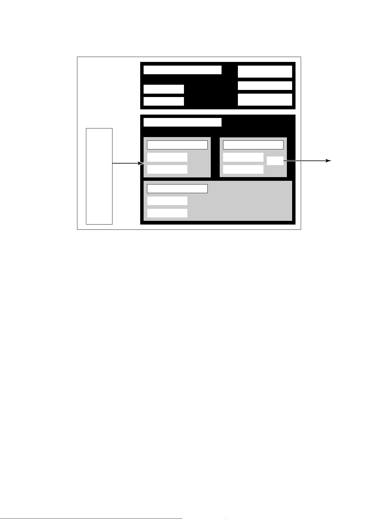
3.3 Correlation of Each Block
YF100
Sensor
Sensor
Input
Management VFD
Device Tag
Node Address
Function Block VFD
Transducer Block
Block Tag
Parameters
Resource Block
Block Tag
Parameters
Communication
Parameters
VCR
Function Block
Execution Schedule
AI function block
AI Function Block
Block Tag
Parameters
OUT
Output
F0301.EPS
Figure 3.1 Correlation of Each Block
Setting of various parameters, node address, and device tag shown in Figure 3.1
is required before starting operation.
3.4 Wiring System Configuration
The number of devices that can be connected to a single bus and the cable length
vary depending on system design. When constructing systems, both the fundamental and overall design, must be carefully considered to allow device performance to be fully exhibited.
3-2
IM 1F2F4-01E
Page 10

4. FOR NOVICE USERS
Fieldbus is fully dependent upon digital communication protocol and differs in
operation from conventional 4 to 20 mA transmission and the BRAIN communication protocol. It is recommended that novice users use field devices in accordance
with the procedures described in this section. The procedures assume that field
devices will be used for laboratories or similar experimental purposes.
4.1 Connection of Equipment
The following equipment is required for use with Fieldbus devices:
• Power supply: Fieldbus requires a dedicated power supply. It is recommended
that current capacity should be well over the total value of the
maximum current consumed by all devices (including the host).
Conventional DC current cannot be used as power supply.
• Terminator: Fieldbus requires two terminators. Refer to the supplier for
details of terminators that are attached to the host.
• Field devices: Connect Fieldbus communication type YF100. Two or more
YF100 (devices) or other devices can be connected.
• Host: Used for accessing field devices. A dedicated host (such as
DCS) is used for an instrumentation line while dedicated communication tools are used for experimental purposes. For
operation of the host, refer to the instruction manual for each
host. No details of the host are explained in the rest of this
material.
• Cable: Used for connecting equipment. Refer to “Guide to Fieldbus” (TI
38K3A01-01E) for details of instrumentation cabling. If the total
length of the cable is in a range of 2 to 3 meters for laboratory
or other experimental use, the following simplified cable (a
twisted pair wire with a cross section of 0.8 mm2 or more (#18
AWG) and cycle period of within 5 cm (2 inches) may be used.
Termination processing depends on the type of device being
deployed. For YF100, use an M3.5 screw terminal claw. Some
hosts require a connector.
4. FOR NOVICE USERS
IM 1F2F4-01E
Refer to Yokogawa when making arrangements to purchase the recommended
equipment.
Connect the equipment as shown in Figure 4.1. Connect the terminators at both
ends of the trunk, with a minimum length of the spur laid for connection.
Be care that the polarity of the terminal is correct.
4-1
Page 11

Fieldbus power
supply
Terminator
YF100
HOST
Terminator
F0401.EPS
Figure 4.1 Cabling
Note: No CHECK terminal is used for Fieldbus communication YF100. Do not connect the field
indicator and check meter.
Before using a Fieldbus configuration tool other than the existing host, confirm it
does not affect the loop functionality in which all devices are already installed in
operation. e.g. disconnect the relevant control loop from the bus.
IMPORTANT
Connecting a Fieldbus configuration tool to a loop with its exsisting host may
cause communication data scrambles resulting in a functional disorder or a system
failure.
4-2
IM 1F2F4-01E
Page 12
4.2 Host Setting
To activate Fieldbus, the following settings are required for the host.
Note: Care must be taken not to turn off the power immediately after setting. If the power is turned off
within 30 seconds after setting is made, the modified parameters are not saved and the settings
revert back to the original values.
Table 4.1 Operation Parameters
Symbol Parameter Description and Settings
V (ST) Slot-Time
V (MID) Minimum-Inter-PDU-Delay
V (MRD) Maximum-Reply-Delay
V (FUN) First-Unpolled-Node
V (NUN) Number-of-consecutive-
Unpolled-Node
0x00
4. FOR NOVICE USERS
Set 4 or greater value.
Set 4 or greater value.
Set so that V (MRD) x V (ST) is 12 or greater
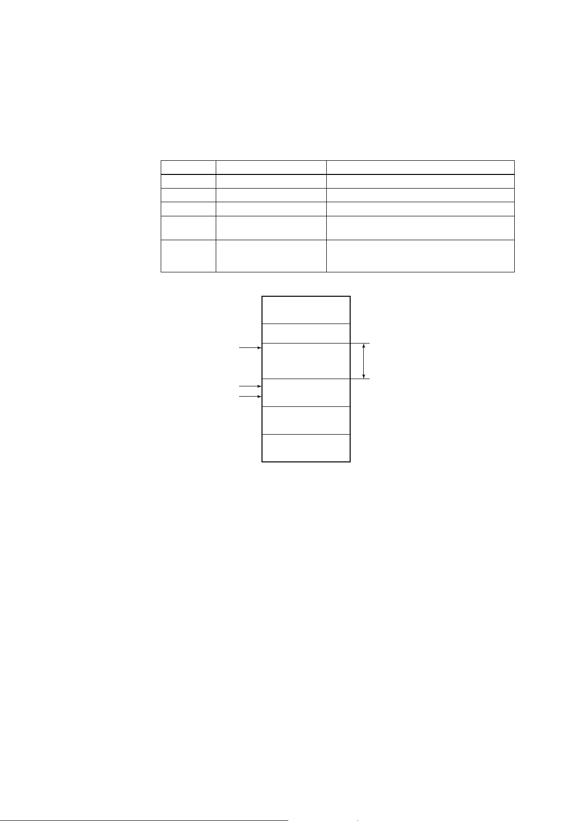
Indicate the address next to the address range
used by the host. Set hex. 15 or greater.
Unused address range. YF100 address is factory-
set to hex. F5. Set this address to be within the
range of the BASIC device in Figure 4.2.
T0401.EPS
Not used
V(FUN)
V(FUN)+V(NUN)
YEWFLO(0xF5)
Note 1: LM device: with bus control function (Link Master function)
Note 2: BASIC device: without bus control function
Figure 4.2 Available Range of Node Address
4.3 Bus Power ON
Turn on the power of the host and the bus. Where the YF100 is equipped with an
LCD indicator, first all segments are lit, then the display begins to operate. If the
indicator is not lit or abnormal current flows, check the polarity of the power supply.
Using the host device display function, check that YF100 is in operation on the
bus. Unless otherwise specified, the following settings are in effect when shipped
from the factory.
0x10
BASIC device
0xF7
0xF8
Default address
0xFB
0xFC
Portable device address
0xFF
LM device
Not used V(NUN)
F0402.EPS
IM 1F2F4-01E
Device tag: FI1001
Node address: 245 (hexadecimal F5)
Device ID: 5945430002xxxxxxxx (xxxxxxxx = a total of 8 alphanumeric
characters)
If no YF100 is detected, check the available address range and the polarity of the
power supply. If two YF100s are connected at a time, only one YF100 will be
detected if both YF100s have the same initial address. Separately connect each
YF100 and set a different address for each.
4-3
Page 13

4.4 Integration of DD
If the host supports DD (Device Description), the DD of the YF100 needs to be
included. Check if the following directory is placed under the directory where the
host DD is to be contained.
594543\0002
(Of this directory, 594543 is the manufacturer number of Yokogawa Electric
Corporation, and 0002 is the YF100 device number, respectively.)
In the absence of this directory, no DD of YF100 has been included. Create the
above directory and copy the DD file (0101.ffo,0101.sym) (option) into the directory.
Once the DD is included in the directory, the name and attribute of all parameters
of the YF100 are displayed.
4.5 Reading the Parameters
To read YF100 parameters, select the AI block of the YF100 from the host screen
and read the OUT parameter. The current flow is displayed.
(Check that MODE_BLK of the function block resource block is set to AUTO.)
4.6 Continuous Record of Settings
If the host has a function of continuously recording the indications, use this function to list the indications (values). Depending on the host being used, it may be
necessary to set the schedule of Publish (the function that transmits the indication
on a periodic basis).
4.7 Generation of Alarm
If the host is allowed to receive alarms, generation of an alarm can be attempted
from YF100. In this case, set the reception of alarms on the host side. YF100’s
VCR-7 and link object-3 are factory-set for this purpose. For practical purposes, all
alarms are placed in a disabled status; for this reason, it is recommended that you
first use one of these alarms on a trial basis.
Since the LO_PRI parameter (index 629) of the AI block is set to “0”, try setting
this value to “3”. Select the Write function from the host in operation, specify an
index or variable name, and write “3” to it.
The LO_LIM parameter (index 630) of the AI block determines the limit at which
the lower bound alarm for the process value is given. In usual cases, a very small
value is set to this limit. Set 10 (meaning 10 kg/min) to the limit. Since the flow is
almost 0, a lower bound alarm is raised. Check that the alarm can be received at
the host. When the alarm is confirmed, transmission of the alarm is suspended.
4-4
The above-mentioned items are a description of the simple procedure to be carried
out until YF100 is connected to Fieldbus. In order to take full advantage of the
performance and functionality of the device, it is recommended that it be read
together with Chapter 5, which describes how to use the YF100.
IM 1F2F4-01E
Page 14

5. CONFIGURATION
This chapter contains information on how to adapt the function and performance of
the YF100 to suit specific applications. Because two or more devices are connected to Fieldbus, settings including the requirements of all devices need to be
determined. Practically, the following steps must be taken.
(1)Network design
Determines the devices to be connected to Fieldbus and checks the capacity of
the power supply.
(2)Network definition
Determines the tag and node address for all devices.
(3)Definition of combining function blocks
Determines the method for combination between each function block.
(4) Setting tag and address
Sets the device address and node address one by one for each device.
(5)Communication setting
Sets the link between communication parameters and function blocks.
(6)Block setting
Sets the parameters for function blocks.
5. CONFIGURATION
The following section describes each step of the procedure in the order given.
Using a dedicated configuration tool allows the procedure to be significantly
simplified. This section describes the procedure to be assigned for a host which
has relatively simple functions.
5.1 Network Design
Select the devices to be connected to the Fieldbus network. The following equipment is necessary for operation of Fieldbus.
• Power supply: Fieldbus requires a dedicated power supply. It is recommended
• Terminator: Fieldbus requires two terminators. Refer to the supplier for
• Field devices: Connect the field devices necessary for instrumentation. YF100
• Host: Used for accessing field devices. A minimum of one device with
• Cable: Used for connecting equipment. Refer to “Guide to Fieldbus” for
that current capacity should be well over the total value of the
maximum current consumed by all devices (including the host).
Conventional DC current cannot be used as power supply.
details of terminators that are attached to the host.
has passed the interoperability test conducted by the Foundation
Fieldbus. In order to smoothly start Fieldbus, it is recommended
that the devices used satisfy the requirements of the above test.
bus control function is needed.
details of instrumentation cabling. Provide a cable sufficiently
long to connect all devices. For field branch cabling, use terminal boards or a connection box as required.
IM 1F2F4-01E
5-1
Page 15

First, check the capacity of the power supply. The power supply capacity must be
greater than the sum of the maximum current consumed by all devices to be
connected to Fieldbus. The maximum current consumed (power supply voltage 9 V
to 32 V) for YF100 is 17 mA. The cable must have the spur in a minimum length
with terminators installed at both ends of the trunk.
5.2 Network Definition
Before connection of devices with Fieldbus, define the Fieldbus network. Allocate
device tags and node address to all devices (excluding such passive devices as
terminators).
The device tag is the same as the conventional one used for the device. Up to 32
alphanumeric characters may be used for definition. Use a hyphen as a delimiter
as required.
The node address is used to specify devices for communication purposes. Because data is too long for a device tag, the host uses the device tag in place of the
node address for communication. A range of 16 to 247 (or hexadecimal 10 to F7)
can be set. The device (LM device) with bus control function (Link Master function)
is allocated from a smaller address number (16) side, and other devices (BASIC
device) without bus control function allocated from a larger address number (247)
side respectively. Place YF100 in the range of the BASIC device. Set the range of
address to be used to the LM device. Set the following parameters.
Table 5.1 Parameters for Setting Address Range
V (FUN) First-Unpolled-Node
V (NUN) Number-of-consecutive-
Unpolled-Node
Indicates the address next to the address range
used for the host or other LM device.
Unused address range
T0501.EPS
The devices within the address range written as “Unused” in Figure 5.1 cannot
participate in Fieldbus. For other address ranges, the range is periodically checked
to identify when a new device is mounted. Care must be taken not to allow the
address range to become wider, which can lead to exhaustive consumption of
Fieldbus communication performance.
0x00
Not used
V(FUN)
V(FUN)+V(NUN)
0x10
0xF7
0xF8
0xFB
0xFC
0xFF
LM device
Not used V(NUN)
BASIC device
Default address
Portable device address
F0501.EPS
5-2
Figure 5.1 Available Range of Node Address
IM 1F2F4-01E
Page 16

5. CONFIGURATION
To ensure stable operation of Fieldbus, determine the operation parameters and
set them to the LM devices. While the parameters in Table 5.2 are to be set, the
worst-case value of all the devices to be connected to the same Fieldbus must be
used. Refer to the specification of each device for details. Table 5.2 lists YF100
specification values.
Table 5.2 Operation Parameter Values of the YF100 to be Set to LM Devices
Symbol Parameters Description and Settings
V (ST) Slot-Time
V (MID) Minimum-Inter-PDU-Delay
V (MRD) Maximum-Reply-Delay
Indicates the time necessary for immediate reply of
thje device. Unit of time is in octets (256 µs). Set
maximum specification for all devices. For YF100,
set a value of 4 or greater.
Minimum value of communication data intervals.
Unit of time is in octets (256 µs). Set the maximum
specification for all devices. For YF100, set a value
of 4 or greater.
The worst case time elapsed until a reply is
recorded. The unit is Slot-time; set the value so
that V (MRD) xV (ST) is the maximum value of the
specification for all devices. For YF100, the setting
must be a value of 12 or greater.
T0502.EPS
5.3 Definition of Combining Function Blocks
The input/output parameters for function blocks are combined. For the YF100, the
output parameter (OUT) for AI block is subject to combination. They are combined
with the input of the control block as necessary. Practically, setting is written to the
YF100 link object with reference to “Block setting” in Section 5.6 for details. It is
also possible to read values from the host at proper intervals instead of connecting
the YF100 block output to other blocks.
The combined blocks need to be executed synchronously with other blocks or the
communications schedule. In this case, change the YF100 schedule according to
the following table. Enclosed values in the table are factory-settings.
Table 5.3 Execution Schedule of the YF100 Function Blocks
Index Parameters Setting (Enclosed is factory-setting)
269 (SM) MACROCYCLE_DURATION
276 (SM) FB_START_ENTRY.1
A maximum of 100ms is taken for execution of AI block. For scheduling of communications for combination with the next function block, the execution is so arranged
as to start after a lapse of longer than 100ms.
Cycle (MACROCYCLE) period of control or
measurement. Unit is 1/32 ms. (32000 = 1 s)
AI block startup time. Elapsed time from the start of
MACROCYCLE specified in 1/32 ms. (0 = 0 s)
T0503.EPS
IM 1F2F4-01E
5-3
Page 17

Macrocycle (Control Period)
LI103 LI100
OUT IN
LC100 LIC100
FC102 FIC100 FC100
BKCAL_IN
CAS_IN
BKCAL_OUT
FI101 FI100
Function Block
Schedule
Communication
Schedule
OUT
IN
BKCAL_IN
Unscheduled Communication
Figure 5.2 Function Block Schedule and Communication Schedule
5.4 Setting of Device Tag and Node Address
This section describes the steps in the procedure to take to set device tags and
node addresses to the YF100. There are three states of Fieldbus devices as
shown in Figure 5.3, and if the state is other than the lowest SM_OPERATIONAL
state, no function block is executed. YF100 must be transferred to this state when
an YF100 Device Tag or Node Address is changed.
(No Device Tag nor Node Address is set)
UNINITIALIZED
BKCAL_OUT
Scheduled
Communication
F0502.EPS
5-4
Device Tag clear Tag setting
INITIALIZED
(Only Tag is set)
Node Address clear
SM_OPERATIONAL
(Tag and address are retained, and
the function block can be executed.)
Node Address setting
F0503.EPS
Figure 5.3 Status Transition by Setting Device Tag and Node Address
YF100 has a device tag (FI1001) and node address (245, or hexadecimal F5) that
are set upon shipment from the factory (unless otherwise specified). To change
only the node address, clear the address once and then set a new node address.
To set the device tag, first clear the node address and clear the device tag, then
set the device address and node address again.
Devices whose node address was cleared will await the default address (randomly
chosen from a range of 248 to 251, or from hexadecimal F8 to FB). At the same
time, it is necessary to specify the device ID in order to correctly specify the
device. The device ID of the YF100 is 5945430002xxxxxxxx. (The xxxxxxxx at the
end of the above device ID is a total of 8 alphanumeric characters.)
IM 1F2F4-01E
Page 18

5.5 Communication Setting
To set the communication function, it is necessary to change the database residing
in SM-VFD.
VCR Setting
Set VCR (Virtual Communication Relationship), which specifies the called party for
communication and resources. YF100 has 8 VCRs whose application can be
changed, except for the first VCR, which is used for management. Each VCR has
the parameters listed in Table 5.4. Parameters must be changed together for each
VCR because modification for each parameter may cause inconsistent operation.
Table 5.4 VCR Static Entry
Subindex Parameter Description
1 FasArTypeAndRole
2 FasDllLocalAddr
3 FasDllConfiguredRemoteAddr
4 FasDllSDAP
5 FasDllMaxConfirmDelayO
nConnect
6 FasDllMaxConfirmDelayO
nData
7 FasDllMaxDlsduSize
8 FasDllResidualActiviey
Supported
9 FasDllTimelinessClass
10 FasDllPublisherTimeWin
dowSize
11 FasDllPublisherSynchro
nizaingDlcep
12 FasDllSubsriberTimeWin
dowSize
5. CONFIGURATION
Indicates the type and role of communication (VCR)
employed. The following 3 types may be used for
YF100.
0x32: Server (Responds to requests from host.)
0x44: Source (Transmits alarm or trend.)
0x66: Publisher (Sends AI block output to other
blocks.)
Set the local address. A range of 20 to F7 in
hexadecimal.
Sets the node address of the called party for
communication and the address (DLSAP or
DLCEP) used to specify VCR in that address. For
DLSAP or DLCEP, a range of 20 to F7 in
hexadecimal is used. Addresses in Subindex 2 and
3 need to be set to the same contents of the VCR
as the called party (local and remote are reversed).
Specifies the quality of communication. Usually,
one of the following types is set.
0x2B: Server
0x01: Source (Alert)
0x03: Source (Trend)
0x99: Publisher
To establish connection for communication, a
maximum wait time for the called party's response
is set in ms. Typical value is 60 seconds (60000).
For request of data, a maximum wait time for the
called party's response is set in ms. Typical value
is 60 seconds (60000).
Specifies maximum DL Service Data Unit Size
(DLSDU). Set 256 for Server and Trend VCR, and
64 for other VCRs.
Specifies whether connection is monitored. Set
YES (0xff) for Server. This parameter is not used
for other communication.
Not used for YF100.
Not used for YF100.
Not used for YF100.
Not used for YF100.
T0504-1.EPS
IM 1F2F4-01E
5-5
Page 19

Subindex Parameter Description
13 FasDllSubscriberSynchr
Not used for YF100.
onizationDlcep
14 FmsVfdId
Sets VFD in YF100 to be used. VfdID of YF100 is
0x1234.
15 FmsMaxOutstandingServi
ceCalling
16 FmsMaxOutstandingServi
ceCalled
17 FmsFeaturesSupported
Set 0 to Server. It is not used for other
applications.
Set 1 to Server. It is not used for other
applications.
Indicates the type of services in the application
layer. In the YF100, it is automatically set
according to specific applications.
Eight VCRs are factory-set as shown in the Table 5.5.
Table 5.5 VCR List
T0504-2.EPS
Index
(SM)
VCR Number Factory Setting
293 For system management (Fixed)1
294 Server (LocalAddr = 0xF3)2
295 Server (LocalAddr = 0xF4)3
296 Server (LocalAddr = 0xF7)4
297 Trend Source (LocalAddr = 0x07)5
298 Publisher (LocalAddr = 0x20)6
299 Al Alert Source (LocalAddr = 0x07)7
300 Server (LocalAddr = 0xF9)8
T0505.EPS
5-6
IM 1F2F4-01E
Page 20

5.6 Block Setting
Set the parameter for function block VFD.
5.6.1 Link Object
Link object combines the data voluntarily sent by the function block with VCR.
YF100 has five link objects. A single link object specifies one combination. Each
link object has the parameters listed in Table 5.6. Parameters must be changed
together for each VCR because the modifications made to each parameter may
cause inconsistent operation.
Table 5.6 Link Object Parameters
Subindex Parameters Description
1 LocalIndex
2 VcrNumber
3 RemoteIndex
4 ServiceOperation
5 StaleCountLimit
Five link objects are factory-set as shown Table 5.7. Usually, settings may be used
as they are and do not need to be changed.
5. CONFIGURATION
Sets the index of function block parameters to be
combined; set “0” for Trend and Alert.
Sets the index of VCR to be combined. If set to “0”,
this link object is not used.
Not used in YF100. Set to “0”.
Set one of the following. Set only one each for link
object for Alert or Trend.
0: Undefined
2: Publisher
6: Alert
7: Trend
Not used in YF100. Set to “0”.
T0506.EPS
Table 5.7 Factory-Settings of Link Objects
Index Link Object # Factory Settings
2000 AI.OUT → VCR#61
2001 Trend → VCR#52
2002 Alert → VCR#73
2003 Not used4
2004 Not used5
T0507.EPS
IM 1F2F4-01E
5-7
Page 21

5.6.2 Trend Object
It is possible to set the parameter so that the function block automatically transmits
Trend. YF100 has three Trend objects, all of which are used for Trend in analog
mode parameters. A single Trend object specifies the trend of one parameter.
Each Trend object has the parameters listed in Table 5.8. The first four parameters
are the items to be set. Before writing to a Trend object, it is necessary to release
the WRITE_LOCK parameter.
Table 5.8 Parameters for Trend Objects
Three trend objects are factory-set as shown Table 5.9.
subindex Parameters Description
1 Block Index
2 Parameter Relative Index
3 Sample Type
4 Sample Interval
5 Last Update
6 to 21 List of Status
21 to 37 List of Samples
Sets the leading index of the function block that
takes a trend. If the YF100, 600 is only available.
Sets the index of parameters taking a trend by a
value relative to the beginning of the function
block. In the YF100, the following three types of
trends are possible.
7: PV
8: OUT
19: FIELD_VAL
Specifies how trends are taken. Choose one of the
following 2 types:
1: Sampled upon execution of a function block.
2: The average value is sampled.
Specifies sampling intervals in units of 1/32 ms.
Set the integer multiple of the function block
execution cycle.
The last sampling time.
Status part of a sampled parameter.
Data part of a sampled parameter.
T0508.EPS
5-8
Table 5.9 Trend Object are Factory-Set
Index Trend Object # Factory Settings
2200 AI OUT1
2201 Not used.2
2202 Not used.3
T0509.EPS
IM 1F2F4-01E
Page 22

5.6.3 View Object
5. CONFIGURATION
This is the object to form groups of parameters in a block. One of advantage
brought by forming groups of parameters is the reduction of load for data transaction. YF100 has four View Objects for each Resource block, Transducer block and
AI1.AI2 function block, and each View Object has the parameters listed in Table
5.10 to 5.12.
Table 5.10 View Object for Resource Block
Relative Index Parameter Mnemonic VIEW_1 VIEW_2 VIEW_3 VIEW_4
1 ST_REV 2
2 TAG_DESC
3 STRATEGY
4 ALERT_KEY
5 MODE_BLK 4
6 BLOCK_ERR 2
7 RS_STATE
8 TEST_RW
9 DD_RESOURCE
10 MANUFAC_ID
11 DEV_TYPE
12 DEV_REV
13 DD_REV
14 GRANT_DENY
15 HARD_TYPES
16 RESTART
17 FEATURES
18 FEATURE_SEL
19 CYCLE_TYPE
20 CYCLE_SEL
21 MIN_CYCLE_T
22 MEMORY_SIZE
23 NV_CYCLE_T
24 FREE_SPACE
26 SHED_RCAS
27 SHED_ROUT
29 SET_FSAFE
30 CLR_FSAFE
31 MAX_NOTIFY
32 LIM_NOTIFY
33 CONFIRM_TIME
34 WRITE_LOCK
35 UPDATE_EVT
36 BLOCK_ALM
38 ACK_OPTION 2
39 WRITE_PRI 1
40 WRITE_ALM
11
425 FREE_TIME
128 FAIL_SAFE
837 ALARM_SUM
2
2
2
1
4
4
4
4
4
4
1
2
4
2
4
1
8
2
2
1
4
2
1
1
2
2
1
4
2
4
IM 1F2F4-01E
Totals (# bytes)
22 32 22 31
T0510.EPS
5-9
Page 23

Table 5.11 View Object for Transducer Block
Relative Index Parameter Mnemonic VIEW_1 VIEW_2 VIEW_3 VIEW_4
1 ST_REV 2
2 TAG_DESC
3 STRATEGY
4 ALERT_KEY
5 MODE_BLK 4
6 BLOCK_ERR 2
7 UPDATE_EVT
8 BLOCK_ALM
9
12 COLLECTION_DIRECTORY
13 PRIMARY_VALUE_TYPE
15 PRIMARY_VALUE_RANGE
16 CAL_POINT_HI
17 CAL_POINT_LO
18 CAL_MIN_SPAN
19 CAL_UNIT
20 SENSOR_TYPE
21 SENSOR_RANGE
22 SENSOR_SN
23 SENSOR_CAL_METHOD
24 SENSOR_CAL_LOC
25 SENSOR_CAL_DATE
26 SENSOR_CAL_WHO
27 LIN_TYPE
28
29
30
31
32
33
34
35
36
37
38
39
40
41
42
43
44
45
TRANSDUCER_DIRECTORY
SECONDARY_VALUE
SECONDARY_VALUE_UNIT
SIZE_SELECT
FLUID_TYPE
K_FACTOR_VALUE
K_FACTOR_UNIT
VISCOSITY_VALUE
VORTEX_FREQ_VALUE
FLOW_VELOCITY_VALUE
REYNOLDS_NUM_VALUE
MIN_DENITY_VALUE
DENSITY_UNIT
TEMPERATURE_F_VALUE
TEMPERATURE_UNIT
DENSITY_F_VALUE
SPE_ENTHALPY_VALUE
ENTHALPY_UNIT
TEMPERATURE_N_VALUE
210 TRANSDUCER_TYPE
111 XD_ERROR
514 PRIMARY_VALUE
4
4
2
2
2
4
4
1
1
4
1
4
1
4
1
4
4
1
4
2
4
2
2
1
5
5
4
4
4
2
2
1
2
11
4
2
2
11
4
1
2
4
T0511_1.EPS
5-10
IM 1F2F4-01E
Page 24

5. CONFIGURATION
Relative Index Parameter Mnemonic VIEW_1 VIEW_2 VIEW_3 VIEW_4
46
47
48
49
50
51
52
53
54
55
56
57
58
59
60
61
62
63
64
65
66
67
68
69
70
71
72
73
74
PRESSURE_F_VALUE
PRESSURE_N_VALUE
DEVIATION
NOISE_BALANCE_VALUE
TRIGGER_LEVEL_VALUE
AMPLIFIER_GAIN_VALUE
INSTRUMENTAL_ERR_ADJ
REYNOLDS_NUM_ADJ
ADJACENT_PIPE_EFFECT
EXPANSION_CORRECTION
HIGH_CUT_FILTER_VALUE
LOW_CUT_FLOW
NOISE_JUDGE_CONTROL
ADJ_FREQUENCY_1_VALUE
ADJ_DATA_1_VALUE
ADJ_FREQUENCY_2_VALUE
ADJ_DATA_2_VALUE
ADJ_FREQUENCY_3_VALUE
ADJ_DATA_3_VALUE
ADJ_FREQUENCY_4_VALUE
ADJ_DATA_4_VALUE
ADJ_FREQUENCY_5_VALUE
ADJ_DATA_5_VALUE
V_F_OUTPUT_SEL
V_F_FREQUENCY_VALUE
MODEL
DISPLAY_MODE
DISPLAY_CYCLE
ALARM_SUM
4
4
4
1
1
1
1
1
1
1
4
4
1
IM 1F2F4-01E
Totals (# bytes)
24
56
33
64
T0511_2.EPS
5-11
Page 25

Table 5.12 View Object for AI Function Block
Relative Index Parameter Mnemonic VIEW_1 VIEW_2 VIEW_3 VIEW_4
1 ST_REV 2
2 TAG_DESC
3 STRATEGY
4 ALERT_KEY
5 MODE_BLK 4
6 BLOCK_ERR 2
7PV
8 OUT 5
9 SIMULATE
10 XD_SCALE
11 OUT_SCALE
12 GRANT_DENY
13 IO_OPTS
14 STATUS_OPTS
15 CHANNEL
16 L_TYPE
17 LOW_CUT
18 PV_FTIME
20 UPDATE_EVT
21 BLOCK_ALM
23 ACK_OPTION
24 ALARM_HYS
25 HI_HI_PRI
26 HI_HI_LIM
27 HI_PRI
28 HI_LIM
29 LO_PRI
30 LO_LIM
31 LO_LO_PRI
32 LO_LO_LIM
33 HI_HI_ALM
34 HI_ALM
35 LO_ALM
36 LO_LO_ALM
37 PULSE_VAL
38 RESET
39 TOTAL
55
519 FIELD_VAL
822 ALARM_SUM
11
11
2
2
2
4
2
5
5
8
2
2
1
2
2
2
1
4
4
2
4
1
4
1
4
1
4
1
4
5-12
Totals (# bytes)
31 26 31 46
T0512.EPS
IM 1F2F4-01E
Page 26

5.6.4 Function Block Parameters
Function block parameters can be read from the host or can be set. For a list of
the parameters of blocks held by the YF100, refer to “List of parameters for each
block of the YF100” in Appendix 1. The following are a list of important parameters
with a guide to how to set them.
MODE_BLK: Indicates the three types of function block modes;
CHANNEL: This is the parameter of the transducer block to be input to the
XD_SCALE: Scale of input from the transducer block. The calibrated range
L_TYPE: Specifies the operation function of the AI block. If set to “Di-
PV_FTIME: Sets the time constant of the damping function within AI block
OUT_SCALE: Sets the range of output (from 0% to 100%). The unit can also
Alarm Priority: Indicates the priority of the process alarm. If a value of 3 or
Alarm Threshold: Sets the threshold at which a process alarm is generated. The
5. CONFIGURATION
Out_Of_Service, Manual, and Auto. In Out_Of_Service mode,
the AI block does not operate. The Manual mode does not
allow values to be updated. The Auto mode causes the measured value to be updated. Under normal circumstances, set
the Auto mode to take effect. The Auto mode is the factory
default.
AI block. AI block is assigned flow, respectively. Do not change
this setting.
is factory set (from 0 point to 100% point). Usually, the unit is
set in kg/min. Changing the unit (can be set only in flow unit)
also causes the unit within the transducer block to be automatically changed. (The unit is automatically changed according to
the unit selected by AI.)
rect”, the input delivered to CHANNEL is directly reflected on
OUT. If set to “Indirect”, scaling by XD_SCALE and
OUT_SCALE is carried out and is reflected on OUT. If set to
“Indirect SQRT”, after scaling by XD_SCALE, the square root is
extracted and the value scaled by OUT_SCALE is reflected on
OUT.
Square root is not utilized for YEWFLO.
(primary delay) in seconds.
be set with ease.
greater is set, an alarm is transmitted. The factory default is 1.
Four types of alarm can be set: HI_PRI, HI_HI_PRI, LO_PRI,
and LO_LO_PRI.
factory default setting is a value that does not generate an
alarm. Four types of alarm can be set: HI_LIM, HI_HI_LIM,
LO_LIM, and LO_LO_LIM.
IM 1F2F4-01E
5-13
Page 27

6. IN-PROCESS OPERATION
This chapter describes the procedure performed when changing the operation of
the function block of the YF100 in process.
6.1 Mode Transition
When the function block mode is changed to Out_Of_Service, the function block
pauses and a block alarm is issued.
When the function block mode is changed to Manual, the function block suspends
updating of output values. In this case alone, it is possible to write a value to the
OUT parameter of the block for output. Note that no parameter status can be
changed.
6. IN-PROCESS OPERATION
6.2 Generation of Alarm
6.2.1 Indication of Alarm
When the self-diagnostics function indicates that a device is faulty, an alarm
(device alarm) is issued from the resource block. When an error (block error) is
detected in each function block or an error in the process value (process alarm) is
detected, an alarm is issued from each block. If an LCD indicator is installed, the
error number is displayed as AL.XX. If two or more alarms are issued, multiple
error numbers are displayed in 2-second intervals.
F0601.EPS
IM 1F2F4-01E
Figure 6.1 Error Identified by Built-in Indicator
6-1
Page 28

Table 6.1 List of Error Messages for Built-in Indicators
LCD
AL-01
AL-02 Amplifier or hardware failure.
AL-03 EEPROM is faulty.
AL-20 The function block is not scheduled.
AL-21 The resource block is in O/S mode.
AL-22 The transducer block is in O/S mode.
AL-23 AI function block is in O/S mode.
AL-41
AL-42
AL-61 Out of the range of the built-in indicator display.
AL-62 Al function blocks are in Simulate mode.
AL-63
6.2.2 Alarms and Events
Following alarm or event can be reported by YF100 as an alert if allowed.
Analog Alerts (Generated when a process value exceeds threshold)
By AI Block Hi-Hi Alarm, Hi Alarm, Low Alarm, Low-Low Alarm
Discrets Alerts (Generated when an abnormal condition is detected)
By Resource Block Block Alarm, Write Alarm
By Transducer Block Block Alarm
By AI Block Block Alarm
Content of Alarms
Noise judgement circuit is faulty.
Out of flow range.
Out of span setting range for maximum and minimum.
Al function block is in MAN mode.
T0601.EPS
Update Alerts (Generated when a important (restorable) parameter is updated)
By Resource Block Update Event
By Transducer Block Update Event
By AI Block Update Event
An alert has following structure:
Table 6.2 Alert Object
Subindex
of Analog
Alert
1 Block Index
2 Alert Key
3 Standard
4 Mfr Type
5
6 Priority
7 Time Stamp
8 Subcode
9 Value
10 Relative Index
11 Unit Index
Subindex of
Discrete
Alert
1
2
3
4
5 Message
6
7
8
9
10
11 9
Subindex of
Update
Alert
1
2
3
4
5
6
7
8
Parameter
Name
Type
Type
Static
Revision
Explanation
Index of block from which alert is
generated
Alert Key copied from the block
Type of the alert
Alert Name identified by manufacturer
specific DD
Reason of alert notification
Priority of the alarm
Time when this alert is first detected
Enumerated cause of this alert
Value of referenced data
Relative index of referenced data
Value of static revision (ST_REV) of
the block
Unit code of referenced data
T0602.EPS
6-2
IM 1F2F4-01E
Page 29

6.3 Simulation Function
The simulation function simulates the input of a function block and lets it operate
as if the data was received from the transducer block. It is possible to conduct
testing for the downstream function blocks or alarm processes.
A SIMULATE_ENABLE jumper is mounted in the YF100 amplifier as a key for
disabling the accidental operation of this behavior. When this jumper is shortcircuited with a pin, simulation is enabled. To initiate the same action from a
remote terminal, if REMOTE LOOP TEST SWITCH is written to the 9th element (a
string of 32 characters) of the TEST_RW parameter (index 308) of the resource
block, the resulting action is the same as the one taken when the above jumper is
mounted. Note that this parameter value is lost when the power is turned OFF. In
simulation enabled status, an alarm is generated from the resource block, and
other device alarms will be masked; for this reason the simulation must be disabled immediately after using this function.
The SIMULATE parameter of AI block consists of the elements listed in Table 6.3
below.
Table 6.3 SIMULATE Parameter
Subindex Parameters Description
1 Simulate Status
2 Simulate Value
3 Transducer Status
4 Transducer Value
5 Simulate En/Disable
When Simulate En/Disable in Table 6.3 above is set to 2, the applicable function
block uses the simulation value set in this parameter instead of the data from the
transducer block. This setting can be used for propagation of the status to the
trailing blocks, generation of a process alarm, and as an operation test for trailing
blocks.
6. IN-PROCESS OPERATION
Sets the data status to be simulated.
Sets the value of the data to be simulated.
Displays the data status from the transducer block.
It cannot be changed.
Displays the data value from the transducer block.
It cannot be changed.
Controls the simulation function of this block.
1: Simulation disabled (standard)
2: Simulation started
T0603.EPS
IM 1F2F4-01E
6-3
Page 30

APPENDIX 1. LIST OF PARAMETERS FOR EACH BLOCK OF YF100
APPENDIX 1. LIST OF PARAMETERS
FOR EACH BLOCK OF THE
YF100
Note: The Write Mode column contains the modes in which each parameter is write enabled.
O/S: Write enabled in O/S mode.
MAN: Write enabled in Man mode and O/S mode.
AUTO: Write enabled in Auto mode, Man mode, and O/S mode.
A1.1 Resource Block
Offset Index ExplanationWrite ModeFactory DefaultParameter Name
0 300 TAG:“RS”Block Header
1 301 –ST_REV
2 302 NullTAG_DESC
3 303 0STRATEGY
4 304 0 1 to 255ALERT_KEY
5 305 AUTOMODE_BLK
6 306 –BLOCK_ERR
7 307 –RS_STATE
8 308 NullTEST_RW
9 309 NullDD_RESOURCE
10 310 0x00594543MANUFAC_ID
11 311 2DEV_TYPE
12 312 1DEV_REV
13 313 1DD_REV
14 314 0GRANT_DENY
15 315 Scalar input
16 316 –RESTART
17 317 Soft write lock
18 318 Soft write lock
HARD_TYPES
FEATURES
supported
Report supported
FEATURE_SEL
supported
Report supported
Block Tag
= O/S
–
AUTO
AUTO
AUTO
AUTO
–
AUTO
–
–
–
–
–
AUTO
–
Valid Range
Information on this block such as Block Tag, DD
Revision, Execution Time etc.
The revision level of the static data associated with the
resource block. The revision value is incremented each
time a static parameter value in this block is changed.
The user description of the intended application of the
block.
The strategy field can be used to identify grouping of
blocks. This data is not checked or processed by the
block.
The identification number of the plant unit. This
information may be used in the host for sorting alarms,
etc.
The actual, target, permitted, and normal modes of the
block.
This parameter reflects the error status associated with
the hardware or software components associated with a
block. It is a bit string, so that multiple errors may be
shown.
State of the resource block state machine.–
Read/write test parameter-used only for conformance
testing and simulation.
String identifying the tag of the resource which contains
the Device Description for this resource.
Manufacturer identification number-used by an interface
device to locate the DD file for the resource.
Manufacturer’s model number associated with the
resource-used by interface devices to locate the DD file
for the resource.
Manufacturer revision number associated with the
resource-used by an interface device to locate the DD
file for the resource.
Revision of the DD associated with the resource-used
by an interface device to locate the DD file for the
resource.
Options for controlling access of host computer and
local control panels to operating, tuning and alarm
parameters of the block.
The types of hardware available as channel numbers.–
Allows a manual restart to be initiated. Several degrees
of restart are possible. They are 1: Run, 2: Restart
resource, 3: Restart with defaults, and 4: Restart
processor.
Used to show supported resource block options.–
Used to select resource block options.AUTO
TA0101-1.EPS
IM 1F2F4-01E
A-1
Page 31

Offset Index ExplanationWrite Mode Valid RangeFactory DefaultParameter Name
19 319 ScheduledCYCLE_TYPE
20 320 ScheduledCYCLE_SEL
21 321 3200 (100ms)MIN_CYCLE_T
22 322 0MEMORY_SIZE
23 323 0NV_CYCLE_T
24 324 0FREE_SPACE
25 325 0FREE_TIME
26 326 –SHED_RCAS
27 327 –SHED_ROUT
28 328 1FAULT_STATE
29 329 1SET_FSTATE
30 330 1CLR_FSTATE
31 331 3MAX_NOTIFY
32 332 3LIM_NOTIFY
33 333 5000 (ms)CONFIRM_TIM
34 334 Unlocked
35 335 –UPDATE_EVT
36 336 –BLOCK_ALM
37 337 EnableALARM_SUM
38 338 0ACK_OPTION
39 339 0 0, 1, 3 to 15 only WRITE_PRI
40 340 –WRITE_ALM
WRITE_LOCK
–
AUTO
–
–
–
–
–
AUTO
AUTO
–
AUTO
AUTO
–
AUTO
AUTO
–
–
AUTO
AUTO
–
1(No Change)
2(Change) only
1(No Change)
2(Change) only
0–MAX_NOTIFY
1(Unlocked)
2(Locked) only
Identifies the block execution methods available for this
resource.
Used to select the block execution method for this
resource.
Time duration of the shortest cycle interval of which the
resource is capable.
Available configuration memory in the empty resource.
To be checked before attempting a download.
Interval between writing copies of NV parameters to
non-volatile memory. Zero means never.
Percent of memory available for further configuration.
YF100 has zero which means a preconfigured resource.
Percent of the block processing time that is free to
process additional blocks. YF100 does not support this.
Time duration at which to give up on computer writes to
function block RCas locations. YF100 does not support
this.
Time duration at which to give up on computer writes to
function block ROut locations. YF100 does not support
this.
Condition set by loss of communication to an output
block, failure promoted to an output block or a physical
contact. When fail-safe condition is set, Then output
function blocks will perform their FSAFE actions.
Allows the fail-safe condition to be manually initiated by
selecting Set.
Writing a Clear to this parameter will clear the device
fail-safe state if the field condition, if any, has cleared.
Maximum number of unconfirmed notify messages
possible.
Maximum number of unconfirmed alert notify messages
allowed.
The minimum time between retries of alert reports.AUTO
If set, no writes from anywhere are allowed, except to
clear WRITE_LOCK. Block inputs will continue to be
updated
This alert is generated by any change to the static data.–
The block alarm is used for all configuration, hardware,
connection failure or system problems in the block. The
cause of the alert is entered in the subcode field. The
first alert to become active will set the Active status in
the Status attribute. As soon as the Unreported status is
cleared by the alert reporting task, another block alert
may be reported without clearing the Active status, if
the subcode has changed.
The current alert status, unacknowledged states,
unreported states, and disabled states of the alarms
associated with the function block.
Priority of the alarm generated by clearing the write
lock.
This alert is generated if the write lock parameter is
cleared.
TA0101-2.EPS
A-2
IM 1F2F4-01E
Page 32

A1.2 Al Function Block
APPENDIX 1. LIST OF PARAMETERS FOR EACH BLOCK OF YF100
Offset Index ExplanationWrite Mode Valid RangeParameter Name
0 600 TAG: “AI”Block Header
1 601 –ST_REV
2 602 (blank)TAG_DESC
3 603 0STRATEGY
4 604 0 1 to 255ALERT_KEY
5 605 AUTOMODE_BLK
6 606 –BLOCK_ERR
7 607 –PV
8 608 –OUT
9 609 DisableSIMULATE
10 610 Specified at the
11 611 Specified at the
XD_SCALE
OUT_SCALE
Factory Default
time of order
time of order
Block Tag
= O/S
–
AUTO
AUTO
AUTO
AUTO
–
–
Value =
MAN
AUTO
MAN
MAN
Information on this block such as Block Tag, DD
Revision, Execution Time etc.
The revision level of the static data associated with the
function block. The revision value will be incremented
each time a static parameter value in the block is
changed.
The user description of the intended application of the
block.
The strategy field can be used to identify grouping of
blocks. This data is not checked or processed by the
block.
The identification number of the plant unit. This
information may be used in the host for sorting alarms,
etc.
The actual, target, permitted, and normal modes of the
block.
This parameter reflects the error status associated with
the hardware or software components associated with a
block. It is a bit string, so that multiple errors may be
shown.
Either the primary analog value for use in executing the
function, or a process value associated with it.
May also be calculated from the READBACK value of
an AO block.
The primary analog value calculated as a result of
executing the function.
Allows the transducer analog input or output to the
block to be manually supplied when simulate is
enabled. When simulation is disabled, the simulate
value and status track the actual value and status.
The high and low scale values, engineering units code,
and number of digits to the right of the decimal point
used with the value obtained from the transducer for a
specified channel.
The high and low scale values, engineering units code,
and number of digits to the right of the decimal point to
be used in displaying the OUT parameter and
parameters which have the same scaling as OUT.
12 612 0GRANT_DENY
13 613 0IO_OPTS
14 614 0STATUS_OPTS
15 615 1CHANNEL
16 616 Specified at the
17 617 0LOW_CUT
18 618 2sec
L_TYPE
time of order
AUTO
O/S
O/S
O/S
MAN
AUTO
AUTO
1 only
1 to 3 only
The value > 0
The value > 0PV_FTIME
Options for controlling access of host computers and
local control panels to operating, tuning and alarm
parameters of the block.
Options which the user may select to alter input and
output block processing
Options which the user may select in the block
processing of status
The number of the logical hardware channel that is
connected to this I/O block. This information defines
the transducer to be used going to or from the physical
world.
Determines if the values passed by the transducer
block to the AI block may be used directly (Direct) or if
the value is in different units and must be converted
linearly (Indirect), or with square root (Ind Sqr Root),
using the input range defined by the transducer and the
associated output range.
Limit used in square root processing. A value of zero
percent of scale is used in block processing if the
transducer value falls below this limit, in % of scale.
This feature may be used to eliminate noise near zero
for a flow sensor.
Time constant of a single exponential filter for the PV, in
seconds.
TA0102-1.EPS
IM 1F2F4-01E
A-3
Page 33

Offset Index ExplanationWrite Mode Valid Range
19 619
20 620 –UPDATE_EVT
Parameter Name
Factory Default
–FIELD_VAL
–
–
Raw value of the field device in percent of thePV range,
with a status reflecting the Transducer condition, before
signal characterization (L_TYPE) or filtering
(PV_FTIME).
This alert is generated by any change to the static data.
21 621 –BLOCK_ALM
22 622 EnableALARM_SUM
23 623 0ACK_OPTION
24 624 0.5% ALARM_HYS
25 625 0HI_HI_PRI
26 626 +INFHI_HI_LIM
27 627 0HI_PRI
28 628 +INFHI_LIM
29 629 0LO_PRI
30 630 –INFLO_LIM
31 631 0LO_LO_PRI
32 632 –INF
33 633 –HI_HI_ALM
34 634 –HI_ALM
LO_LO_LIM
–
–
AUTO
AUTO
AUTO
AUTO
AUTO
AUTO
AUTO
AUTO
AUTO
AUTO
–
–
0 to 50
0, 1, 3 to 15
Note 1
0, 1, 3 to 15
Note 1
0, 1, 3 to 15
Note 2
0, 1, 3 to 15
Note 2
The block alarm is used for all configuration, hardware,
connection failure or system problems in the block. The
cause of the alert is entered in the subcode field. The
first alert to become active will set the Active status in
the Status attribute. As soon as the Unreported status is
cleared by the alert reporting task, another block alert
may be reported without clearing the Active status, if
the subcode has changed.
The current alert status, unacknowledged states,
unreported states, and disabled states of the alarms
associated with the function block.
Selection of whether alarms associated with the block
will be automatically acknowledged.
Amount the PV must return within the alarm limits
before the alarm condition clears. Alarm Hysteresis is
expressed as a percent of the PV span.
Priority of the high high alarm.
The setting for high high alarm in engineering units.
Priority of the high alarm.
The setting for high alarm in engineering units.
Priority of the low alarm.
The setting for the low alarm in engineering units.
Priority of the low low alarm.
The setting of the low low alarm in engineering units.
The status for high high alarm and its associated time
stamp.
The status for high alarm and its associated time stamp.
35 635 –LO_ALM
36 636 –LO_LO_ALM
37 637 5 (E+5)PULSE_VAL
38 638 0 (OFF)
39 639 –TOTAL
Note 1: When Min (OUT_SCALE.EU0, OUT_SCALE.EU100) ≤ set value ≤ + INF, it is write-able.
Note 2: When -INF ≤ set value ≤ Max (OUT_SCALE .EU0,OUT_SCALE.EU100), it is write-able.
–
–
O/S
AUTO
–
0 to 13
0 (Off), 1 (Reset) onlyRESET
The status of the low alarm and its associated time
stamp.
The status of the low low alarm and its associated time
stamp.
Set the factor per totalized value count when a totalized
flow is necessary.
Totalized value (display & RAM data) are reset when
this function is executed.
Totalized value.
TA0102-2.EPS
A-4
IM 1F2F4-01E
Page 34

A1.3 Transducer Block
Offset Index ExplanationWrite Mode Valid RangeFactory DefaultParameter Name
0 400 TAG: “TB”Block Header
1 401 –ST_REV
2 402 (blank)TAG_DESC
3 403 0STRATEGY
4 404 1 1 to 255ALERT_KEY
5 405 AUTOMODE_BLK
6 406 –BLOCK_ERR
7 407 –UPDATE_EVT
8 408 –BLOCK_ALM
9 409 –TRANSDUCER_
10 410 104: Flow with
11 411 –XD_ERROR
12 412 –COLLECTION_
13 413 100: Mass flow
14 414 –PRIMARY_
15 415 Range of flowPRIMARY_
16 416 Max rangeCAL_POINT_HI
17 417 Min. rangeCAL_POINT_LO
18 418 FlowCAL_MIN_SPAN
19 419 1349: m
20 420 Vortex
21 421 Flow rangeSENSOR_
22 422 Serial No.SENSOR_SN
23 423 100: VolumetricSENSOR_CAL_
24 424 SENSOR_CAL_
25 425 SENSOR_CAL_
26 426 –SENSOR_CAL_
27 427 1LIN_TYPE
28 428 –SECONDARY_
29 429 1088: kgSECONDARY_
30 430 25 mm
DIRECTORY
TRANSDUCER_
TYPE
DIRECTORY
PRIMARY_
VALUE_TYPE
VALUE
VALUE_RANGE
RANGE
METHOD
LOC
DATE
WHO
VALUE
VALUE_UNIT
SIZE_SELECT
Calibration
101: Volumetric flow
3
/hCAL_UNIT
–
–
Block Tag
= O/S
–
AUTO
AUTO
AUTO
AUTO
–
–
–
–
O/S
–
–
–
O/S
O/S
O/S
–
APPENDIX 1. LIST OF PARAMETERS FOR EACH BLOCK OF YF100
Information on this block such as Block Tag, DD
Revision, Execution Time etc.
The revision level of the static data associated with the
function block. The revision value will be incremented
each time a static parameter value in the block is
changed.
The user description of the intended application of the
block
The strategy field can be used to identify grouping of
blocks. This data is not checked or processed by the
block.
The identification number of the plant unit.
This information may be used in the host for sorting
alarms, etc.
The actual, target, permitted, and normal modes of the
block.
This parameter reflects the error status associated with
hardware or software components associated with a
block. It is a bit string, so that multiple errors may be
shown.
This alert is generated by any change to the static data.–
The block alarm is used for all configuration, hardware,
connection failure or system problems in the block. The
cause of the alert is entered in the subcode field. The
first alert to become active will set the Active status in
the Status attribute.
A directory that specifies the number and starting
indices of the transducers.
104: Flow with
Calibration
100 to 109
Note 1
Note 2
Note 3
112:Vortex onlySENSOR_TYPE
100 to 106
0, 1, 255
Only displayed units
are write enabled
0:15 mm to
16:200 mmHPT
Identifies transducer.–
The error code in transducer.–
A directory that specifies the number, starting indices,
and DD Item Ids of the data collections in each
transducer within a transducer block.
The type of measurement represented by primary
value.
The measured value and status available to the function
block.
The High and Low range limit values, engineering units
code and the number of digits to the right of the decimal
point to be used to display the primary value.
The highest calibrated value.O/S
The lowest calibrated value.O/S
The minimum calibration span value allowed.–
The engineering unit for the calibrated values.–
The type of sensor.–
The High and Low range limit values, engineering units
code and the number of digits to the right of the decimal
point for the sensor.
The sensor serial number.–
The method of the last sensor calibration.O/S
The location of the last sensor calibration.
The date of the last sensor calibration.
The name of the person responsible for the last sensor
calibration.
The secondary value (totalized value) of transducer.–
The engineering unit of secondary value.–
The nominal size of combined detector.O/S
TA0103-1.EPS
IM 1F2F4-01E
A-5
Page 35

Offset Index ExplanationWrite Mode Valid RangeFactory DefaultParameter Name
31 431 Steam MFLUID_TYPE
32 432 68.6K_FACTOR_
VALUE
33 433 P/LK_FACTOR_
UNIT
34 434 1VISCOSITY_
VALUE
35 435 –VORTEX_FREQ
_VALUE
36 436 –FLOW_VELOCITY
_VALUE
37 437 –REYNOLDS_
NUM_VALUE
38 438 1MIN_DENSITY_
VALUE
39 439 Kg/m
DENSTY_UNIT
40 440 15TEMPERATURE_
F_VALUE
41 441 DegCTEMPERATURE_
UNIT
42 442 1DENSITY_F_
VALUE
43 443 1SPE_ENTHALPY
_VALUE
44 444 Kcal/kgENTHALPY_
UNIT
45 445 15TEMPPERATURE
_N_VALUE
46 446 1.0332PRESSURE_F_
VALUE
47 447 1.0332PRESSURE_N
VALUE
48 448 1DEVIATION
49 449 0NOISE_BALANCE
_VALUE
50 450 0TRIGGER_LEVEL
_VALUE
51 451 0AMPLIFIER_
GAIN_VALUE
52 452 0INSTRUMENTAL_
ERR_ADJ
53 453 0REYNOLDS_
NUM_ADJ
54 454 0ADJACENT_PIPE
_EFFECT
55 455 0EXPANSION_
CORRECTION
56 456 0HIGH_CUT_
FILTER_VALUE
57 457 0.06122LOW_CUT_
FLOW
58 458 1NOISE_JUDGE_
CONTROL
59 459 0ADJ_
FREQUENCY_
1_VALUE
60 460 0ADJ_DATA_1_
VALUE
61 461 0ADJ_
FREQUENCY_2
_VALUE
The type of flow fluid.O/S
The K-factor value (KM) at 15degC for combined
detector.
The unit of K-factor.O/S
O/S
0:Stream M to 7:Liq M
0 to 32000
0:p/L, 1:p/gal,
2:p/lmpGal
O/S
0 to 32000
The viscosity coefficient of low fluid to output the
Reynolds number.
The vortex frequency.–
The flow velocity value.–
The reynolds number–
0 to 32000
3
1097:kg/m
1107:lb/ft
3
3
The minimum density value under operating condition.O/S
The density unit under operating condition.O/S
1108:lb/gal
–500 to 1000
1001:degC
The fluid temperature under operating condition.O/S
The temperature unitO/S
1002:degF
0 to 32000
0 to 32000
1515:kcal/kg
The density value under operationg condition.O/S
The value of specific enthalpy.O/S
The unit of specific enthalpy.O/S
1208:kJ/kg
1516:Btu/lb
The fluid temperature under standard condition.O/S
The absolute pressure value (kg/cm
2
abs) under
operating condition.
The absolute pressure value (kg/cm2 abs) under
standard condition.
The deviation factor.O/S
The noise balance adjustment.O/S
The trigger level adjustment.O/S
The flowmeter gain can be adjusted.O/S
The parameter to correct the instrumental error.O/S
The parameter to correct the reynolds number’s shift
error.
The parameter to correct the measurement errors
caused by pipe schedules 10, 40, and 80
The parameter to corrects the deviation from the ideal
gas law when measuring a compressibility gas by mass
O/S
O/S
O/S
O/S
O/S
–500 to 1000
0 to 32000
0 to 32000
0 to 10
–5 to 10
–1 to 2
Note 4
0:Off, 1:On
0:Off, 1:On
0:Off to
6:Flange Sch80
0:Off, 1:On
flow and standard condition.
–
–
O/S
O/S
O/S
O/S
Note 5
0 to
XD_SCALE.EU100
0:Off, 1:On
0 to 32000
–100 to 100
0 to 32000
The control high cut filter to minimize the effect of high
frequency noise.
The parameter to eliminate noise in the low-frequency
(low flow rate) area.
The parameter to eliminate pipe vibration effect when
flowrate is close to zero.
The first break-point frequency for the instrumental error
adjustment.
The correcting value (%) at the first break-point
frequency for the instrumental error adjustment.
The second break-point frequency for the instrumental
error adjustment.
TA0103-2.EPS
A-6
IM 1F2F4-01E
Page 36

Offset Index ExplanationWrite Mode Valid RangeFactory DefaultParameter Name
62 462 0 –100 to 100ADJ_DATA_2_
VALUE
63 463 0ADJ_
FREQUENCY_3
_VALUE
64 464 0ADJ_DATA_3_
VALUE
65 465 0ADJ_
FREQUENCY_4
_VALUE
66 466 0ADJ_DATA_4_
VALUE
67 467 0ADJ_
FREQUENCY_5
_VALUE
68 468 0ADJ_DATA_5_
VALUE
69 469 0V_F_OUTPUT_
SEL
70 472 –V_F_
FREQUENCY_
VALUE
71 471 YF100*EMODEL
O/S
O/S
O/S
O/S
O/S
O/S
O/S
–
–
APPENDIX 1. LIST OF PARAMETERS FOR EACH BLOCK OF YF100
The correcting value (%) at the second break-point
frequnecy for the instrumental error adjustment.
0 to 32000
–100 to 100
0 to 32000
–100 to 100
0 to 32000
–100 to 100
0:Normal, 1-2:Temp.
3:TP2, 4:Amplitude
The third break-point frequency for the instrumental
error adjustment.
The correcting value (%) at the third break-point
frequnecy for the instrumental error adjustment.
The fourth break-point frequency for the instrumental
error adjustment.
The correcting value (%) at the fourth break-point
frequency for the instrumental error adjustment.
The fifth break-point frequency for the instrumental error
adjustment.
The correcting value (%) at the fifth break-point
frequency for the instrumental error adjustment.
The output of V/F circuit frequency
(V_F_FREQUENCY_VALUE).
The frequency corresponding to the value which is
selected in V_F_OUTPUT_SEL.
The model name of flow converter.–
72 472 1DISPLAY_MODE
73 473 1
CYCLE
74 474 –ALARM_SUM
Note 1: When CAL_POINT_LO< set value, set value < SENSOR_RANGE, EU100, it is write-able only.
Note 2: When CAL_POINT_HI > set value, set value < SENSOR_RANGE, EU100, it is write-able only.
Note 3: Only the flow rate unit is write-able (see parameter description)
Note 4: Set to one of 16 steps between -15 to 15 depending on diameter.
Note 5: The center value (0 value) is shifted in 16 steps between -15 to 15 depending on the
1:Flow unit, 2:%, 3:Total
1 to 255DISPLAY_
–
The display content of the indicator.–
The renewal cycle of the indicator.–
The current alert status, unacknowledged status,
unreported status and disabled status of the alarms
associated with the function block.
XD_SCALEEU100 value.
The limit value is used when a value larger than the limit value is set.
TA0103-3.EPS
IM 1F2F4-01E
A-7
Page 37

APPENDIX 2. APPLICATION, SETTING
AND CHANGE OF BASIC
PARAMETERS
A2.1 Applications and Selection of Basic Parameters
Setting Item (applicable parameters)
Tag No.
Calibration
(XD_SCALE)
Output scale
(OUT_SCALE)
Scale range and unit of built-in
indicator
(OUT_SCALE)
Output mode
(L_TYPE)
Output signal low cut
(LOW_CUT)
Damping time constant
(PV_FTIME)
Simulation
(SIMULATE)
LCD display
(DISPLAY_MODE,
DISPLAY_CYCLE)
Calibration range plus real input
(CAL_POINT_HI, CAL_POINT_LO)
Summary
Sets the device tag and each block tag.
Up to 32 alphanumeric characters can be set for both tags.
Refer to “Tag and address” in Section 5.4.
Sets the range of input from the transducer block corresponding to the 0% and 100%
points in operation within the AI function block. The calibrated range (0% and 100%) is the
factory default setting.
Sets the range unit, input value of the 0% point (lower bound of calibration range), input
value of the 100% point (upper bound of calibration range), and the 4 data at the decimal
point.
Sets the scale of output corresponding to the 0% and 100% points in operation within the
AI function block. It is possible to set a unit and scale that differs from the calibration
range.
Sets the range unit, input value of the 0% point (lower bound of output scale), input value
of the 100% point (upper bound of output scale), and the 4 data at the decimal point.
The range determined with the output scale becomes the scale and unit of the built-in
indicator.
Note: If a built-in indicator is available, the lower bound and the upper bound of the range
(numeric string excluding the decimal point if it is included) may be set in a range
from -65535 to 65535. Down to the third decimal position can be set.
Selects the operation function of the AI function block. It may be chosen from among
Direct, Indirect, and IndirectSQRT.
Direct:
Indirect:
IndirectSQRT:
If the output falls below the setting of this parameter, the output is set to Zero. It can be
set individually with Direct, Indirect, and IndirectSQRT.
Sets the time constant of the damping (primary delay) function in the AI function block in
seconds.
Performs simulation of the AI function block.
The input value and status for the calibration range can also be set.
It is recommended that this parameter be used for loop checks and other purposes. Refer
to “Simulation Function” in Section 6.3.
Sets the unit to be displayed on the LCD and the display speed.
Adjust display speed if a low temperature environment causes a poor LCD display quality.
Sets the range corresponding to the 0% and 100% points while adding the real input. It is
possible to set output to correctly match the user’s reference device output.
The output of the transducer block is directly output only via filtering without
scaling and square root extraction.
Output processed by proportion at the AI function block.
Output processed by square root extraction at the AI function block.
TA0201.EPS
A-8
IM 1F2F4-01E
Page 38

APPENDIX 2. APPLICATION, SETTING AND CHANGE OF BASIC PARAMETERS
A2.2 Setting and Change of Basic Parameters
This section describes the procedure taken to set and change the parameters for
each block. Obtaining access to each parameter differs depending on the configuration system used. For details, refer to the instruction manual for each configuration system.
Access the block mode (MODE_BLK) of each block.
Set the Target
(*Note 1)
of block mode (MODE_BLK) to Auto, Man or O/S
(*Note 2)
according to the Write Mode of the parameter to be set or changed.
Access the parameter to be set or changed.
Make setting or change in accordance with each parameter.
Set the Target of block mode (MODE_BLK) back to Auto
(*Note 2)
.
FA0201.EPS
NOTE
Do not turn the power OFF immediately after parameter setting. Should the power
be turned OFF 30 seconds after setting of parameters, changed parameters are
not saved and revert back to their original values.
IM 1F2F4-01E
Note 1: Block mode consists of the following four modes that are controlled by the universal parameter
that displays the running condition of each block.
Target (Target mode): Sets the operating condition of the block.
Actual (Real mode): Indicates the current operating condition.
Permit (Allowable mode): Indicates the operating condition that the block is allowed to take.
Note 2: The following are the operating conditions which the individual blocks will take.
Automatic (Auto) YesYesYes
Manual (Man)
Out of Service (O/S)
Normal (Usual mode): Indicates the operating condition that the block will usually take.
AI Function Block
Yes
Yes Yes Yes
Transducer Block Resource Block
TA0202.EPS
Refer to the “List of parameters for each block of the YF100” for details of the
Write Mode for each block.
A-9
Page 39

A2.3 Setting the AI Function Block
The AI function block controls operation of output of flow.
(1) Setting the calibration range
Access the XD_SCALE parameter.
Set the upper bound of the input range to EU at 100% on XD_SCALE.
Set the lower bound of the input range to EU at 0% on XD_SCALE.
Set the necessary unit to Units Index.
Set the decimal position of 2 to Decimal Point.
Example:
To measure 0 to 100 kg/min,
Set 100 to EU at 100% on XD_SCALE,
Set 0 to EU at 0% on XD_SCALE, and
Set 1323 to Units Index on XD_SCALE
Note 1: Each unit is expressed using a 4-digit numeric code. Refer to the applicable table for each unit
and the corresponding 4-digit codes.
(2) Setting the output range
(*Note)
FAP02.EPS
.
Access the OUT_SCALE parameter.
Set an output value corresponding to the upper bound of the input range to
EU at 100% on XD_SCALE.
Set an output value corresponding to the lower bound of the input range to
EU at 0% on XD_SCALE.
Set the necessary unit of output to Units Index.
Set the decimal position to Decimal Point.
FA0203.EPS
Example:
To set the output to 0.0 to 100.0%,
Set 100 to EU at 100% on XD_SCALE,
Set 0 to EU at 0% on XD_SCALE,
Set 1324 to Units Index on XD_SCALE , and
Set 2 to Decimal Point on OUT_SCALE.
Restrictions imposed when the device is equipped with a built-in indicator.
For a built-in indicator, the range determined by the output range corresponds to
the scale and unit of the indicator. Set the lower bound and upper bound of the
range (numeric string excluding decimal point if the decimal point is included) in a
range of –65535 to 65535. Down to the third decimal position can be set.
A-10
IM 1F2F4-01E
Page 40

APPENDIX 2. APPLICATION, SETTING AND CHANGE OF BASIC PARAMETERS
(3) Setting the output mode
Access the L_TYPE parameter.
Set the output mode.
1: Direct
2: Indirect
3: IndirectSQRT
(Sensor output value)
(Linear output value)
(Square root extraction output value)
(4) Setting the output signal Low Cut
Set the low cut value.
Access the LOW_CUT parameter.
Set the value subject to LOW_CUT.
Access the IO_OPTS parameter.
Turn Low cutoff ON.
If Low cutoff is turned OFF, Low cut function is released.
FA0204.EPS
FA0205.EPS
(5) Setting the damping time constant
Access the PV_FTIME parameter.
Set the time subject to damping (in seconds).
(6) Simulation
By optionally setting the input value to the calibration range and status, perform
simulation of the AI function block.
Access the Simulate Status parameter.
Set the status code.
Access the Simulate Value parameter.
Set an optional input value.
Access the Simulate En/Disable parameter.
Set whether Simulation is enabled or disabled.
1: Disabled
2: Enabled
FA0206.EPS
FA0207.EPS
IM 1F2F4-01E
If simulation is enabled, AI block uses Simulate Status and Simulate Value as
the input, and if disabled, the AI block uses Transducer Status and Transducer
Value as input.
A-11
Page 41

A2.4 Setting the Transducer Block
To access function specifics to the the YF100 of the transducer block, DD (Device
Description) for YF100 needs to have been installed in the configuration tool used.
For integration of DD, refer to “Integration of DD” in Section 4.4.
Setting the LCD display
Access the DISPLAY_MODE parameter and set the unit of display.
1: Real item display (Default) 2: % display 3: Totalized Flow
Access the DISPLAY_CYCLE parameter and set display cycle.
The display cycle is 500 mS x (setting).
It defaults to 1, but if the LCD display quality looks poor when used in lower
temperature environments, increase the value as required.
FA0208.EPS
A-12
IM 1F2F4-01E
Page 42

APPENDIX 3. OPERATION OF EACH PARAMETER IN THE EVENT OF FAILURE
APPENDIX 3. OPERATION OF EACH
PARAMETER IN THE EVENT
OF FAILURE
• Operation of each parameter in the event of failure
Cause
Sensor failure AL. 01
Amplifier failure
Communication failure AL. 02 Device Needs
EEPROM (FB) failure AL. 03 –
Function block
unscheduled
RS block
O/S mode
TR block
O/S mode
AI block
O/S mode
Abnormal flow
Abnormal parameter AL. 42 –
Out of LCD display
range
AI block
Simulate mode
AI block
MAN mode
LCD
display
AL. 02 Device Needs
AL. 20 ––––
AL. 21 –
AL. 22 Out of Service
AL. 23 –
AL. 41 –
AL. 61 –
AL. 62 –
AL. 63 –
TR block
BROCK ERR
Input Failure
Maintenance Now
Maintenance Now
TR block
XD_ ERROR
Mechanical
Failure z
I/0
Failure
Electronics
Failure
–
–
–
–
–
–
–
–
–
TR block
PV STATUS
Bad:
Sensor Failure
Bad:
Device Failure
Bad:
Device Failure
Bad:
Non Specific
Bad:
Non Specific
Bad:
Out of Service
–
Uncertain:
Sensor Conversion
Not Accurate
Uncertain:
Subnormal
–
–
–
Bad:
Sensor Failure
Bad:
Device Failure
Bad:
Device Failure
Bad:
Non Specific
Bad:
Non Specific
Bad:
Out of Service
–
Uncertain:
Subnormal
Uncertain:
Sensor Conversion
Not Accurate
–
–
–
TR block
SV STATUS
TA0301.EPS
IM 1F2F4-01E
A-13
 Loading...