

Page 1
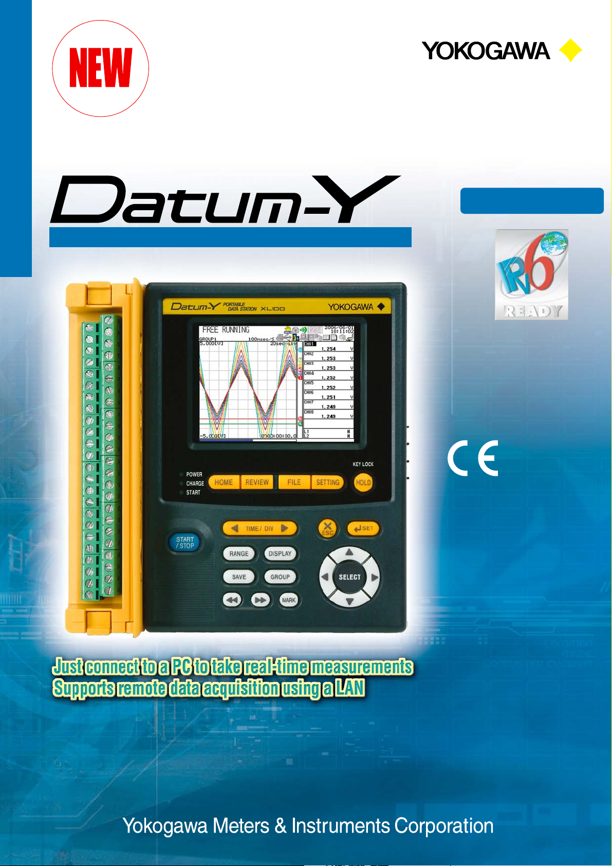
Compact and Noise-resistant Data Logger
T M
Data Logger
A world’s first in measuring
instruments!
To obtain IPv6 Ready Logo Phase-1 cer tification
ID : 01-000273
Size: 155 (W)⫻155 (H)⫻55 (D) mm
Weight: Approx. 800 g
(Without battery and rubber boot)
Bulletin XL120-E
Page 2
Main Features
Application Examples
Wide-view TFT LCD Screen
Datum-Y adopts a color TFT
LCD screen offering a wide
angle of view,
so displayed data can be
read clearly even from angled
directions.
You can select a desired
display mode from among
Wavefor m, Digital,
Bar Graph and Waveform +
Digital.
All Channels Adopt Universal Insulated Inputs
The channels in the analog input part adopt
insulated inputs, which means that temperature
(thermocouple/resistance temperature detector)
and voltage can be set differently for each
channel.
Eleven types of thermocouples, Pt100 and
JPt100 temperature-measuring resistors, and a
voltage up to 50 V range are supported.
Detachable Terminal Block
Wiring is easy, since the terminal block
can be removed with a single action.
Built-in terminal screwdriver
Te r minal block (for 16 channels)
Compact Size
External dimensions: 155 × 155 × 55(mm)
Weight: Approx. 800 g
Easy to carry
Space Saving
The analog inputs are wired from the left, while the
power and communication lines are wired from the
right. This design makes Datum-Y a suitable option in a
narrow space.
Main Functions are Directly Accessible with Just the Push of a Button
HOME
REVIEW
FILE
SETTING
Free running, logging screen, system
information, etc.
Reviewing data after acquisition and
reviewing measurement data while logging
Deleting and copying measurement data and
file processing such as media formatting
Configuring the settings of Datum-Y
M3 screws terminal block
(for 16 channels)
* Taking measurements with a resistance temperature
detector (RTD) is not possible.
2
Built-in rechargeable batteriy
The dedicated lithium ion battery enables
up to 7 hours of operation (in conditions
recommended by Yokogawa).
Rubber Boot (Standard Accessory)
Resistance to impact is improved by the use of a rubber
boot, which is removable.
Page 3
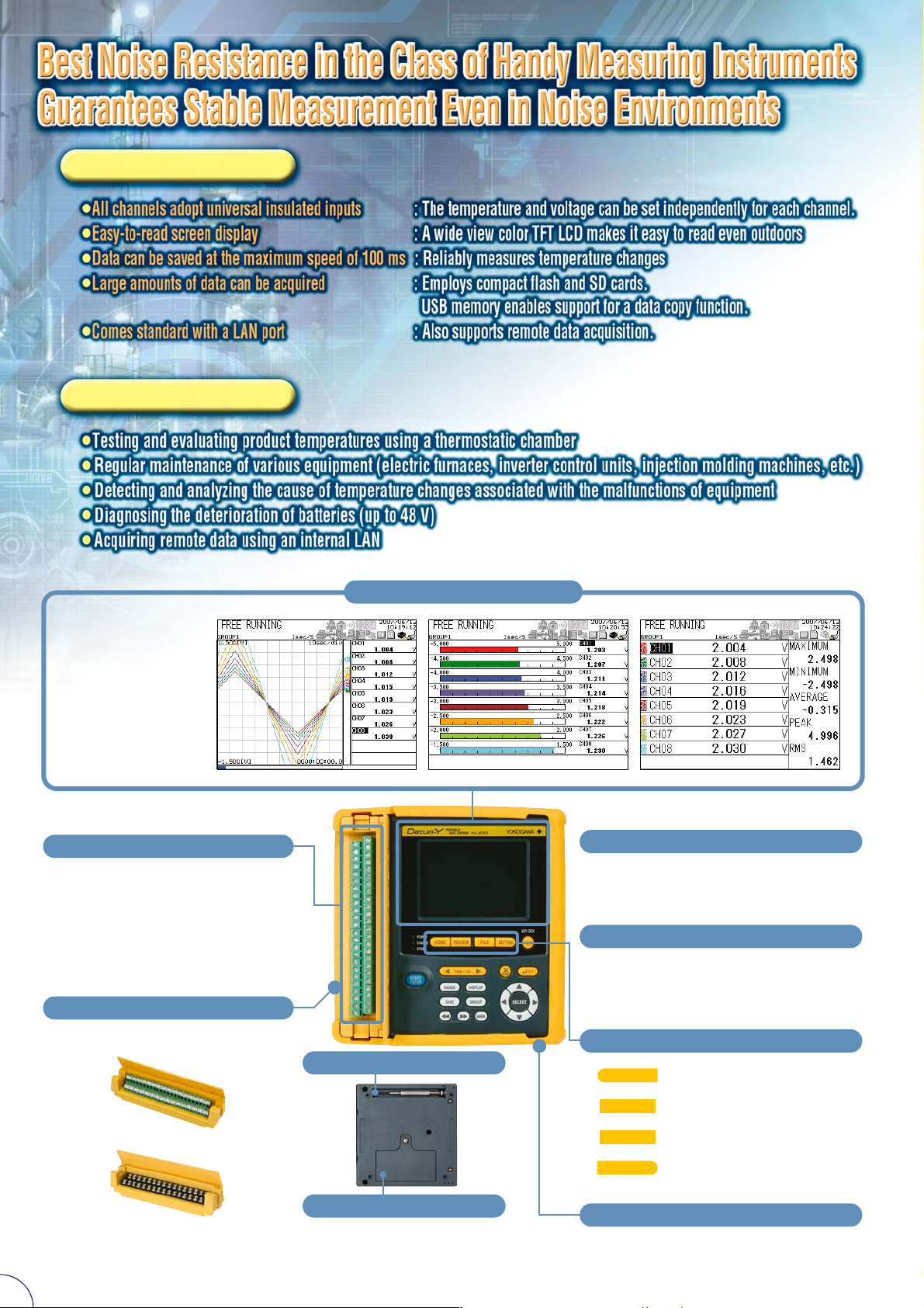
Variety of Functions Facilitate Measurement and Data Acquisition
Spot Check of Acquired Data
You can check measured data
(binary) on Datum-Y right away.
Overall trend and alarm output can
be checked on the spot immediately
after acquisition.
While Datum-Y is logging data, you
can display past data and current
data in the logging review mode for
comparison and identification of
trend. (This function is available
only when binary data is acquired.)
Screen in Logging Review Mode
Calculation Function
Datum-Y is capable of four arithmetic functions (among channels, between
channels and constants, etc.), statistical operations (minimum, maximum,
average, root-mean-square and peak values from start to end of logging), and
scaling.
Alarm Function
Datum-Y can be fitted with up to four alarm output channels. One alarm can be
set for each input channel, and multiple channels can be combined freely with
AND/OR gates. You can also use the e-mail delivery function to notify specified email addresses upon occurrence or reset of an alarm.
Trigger Function
You can use the pretrigger/trigger delay function,
which is convenient when you
detect and analyze the cause of
an error. You can start to
acquire data before and after a
trigger for up to 600
measurements, respectively.
(Pre-trigger starts data
acquisition before the trigger,
while trigger-delay starts data
acquisition after the trigger)
Pre-trigger
Starts saving data
Tr igger issued
Trigger delay
Starts saving data
File Split and Media Overwrite Functions
You can split a measurement data file at a specified time (hours and minutes)
while you are logging data. Furthermore, you can select the following save
options: Delete and Save to delete past measurement data and create new data
when the storage capacity of the destination storage media is full, Repeat Save
to overwrite the old data in the file during measurement, and Stop to stop the
saving. In addition, you can use the FTP function to acquire data stored in
Datum-Y without stopping measurement.
Acquisition of Large Amounts of
Data Using External Storage Media
Acquisition of Large Amounts of Data Using External Storage Media
Datum-Y lets you save data not only in its internal memory (16 MB), but
also in external storage media such as compact flash memory cards*
and SD cards* (up to 512 MB).
Data saved in these media can be copied to a USB memory* for easy
transfer to a PC.
* Use compact flash memory cards, SD cards and/or USB memory whose
compatibility with Datum-Y has been verified.
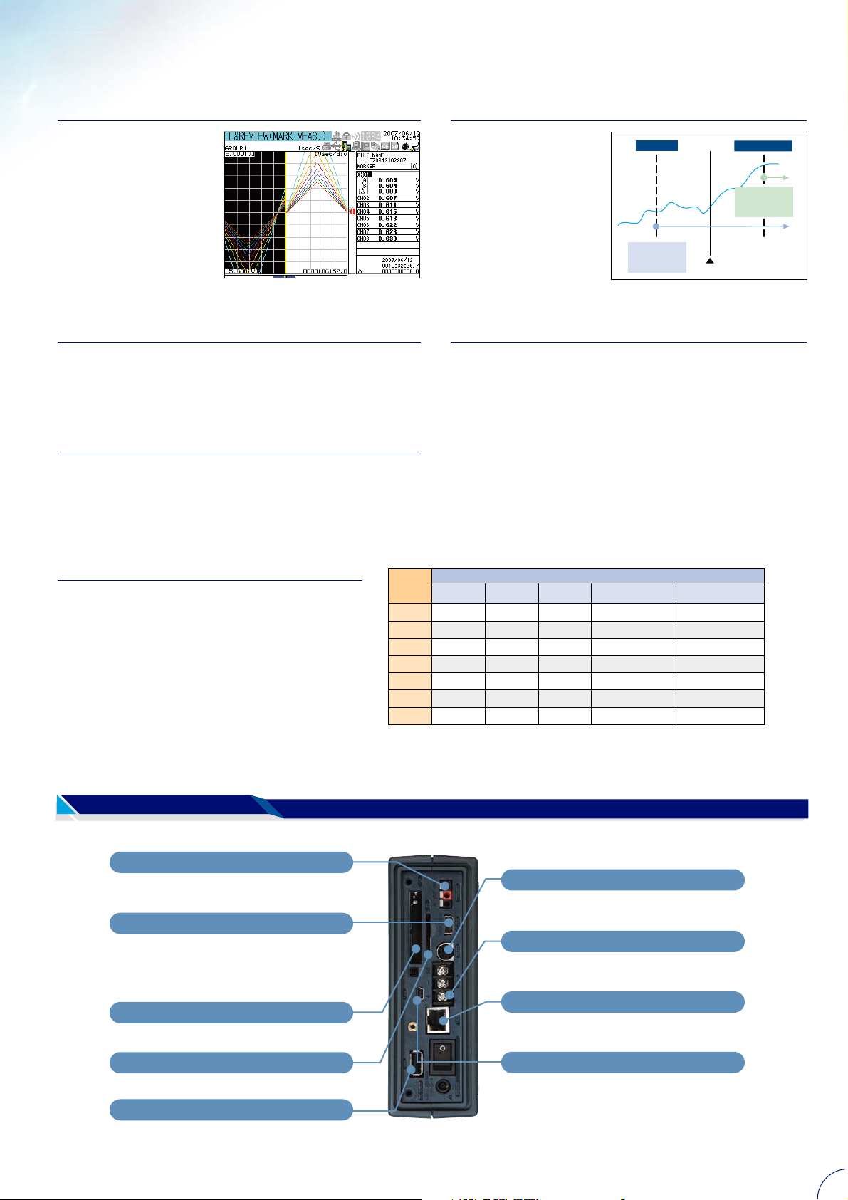
-Side-
External Trigger Input/Output
For connecting another device and synchronizing
measurements.
Digital Input/Output
For using pulse input (on one channel), logic inputs
(on two channels), and alarm outputs (on four
channels) via optional digital input/output cables
(91029).
Type II Compact Flash Slot
For saving data to a compact flash memory card
Recording time (approximate): When a 512 MB external storage medium
(One year is counted as 365 days.)
is used
Measurement
interval
100ms
200ms
500ms
1 sec
2 sec
5 sec
10 sec
1ch
1.6 years
3.2 years
8.1 years
–
–
–
–
Number of measurement channels
16ch8ch
74 days
148 days
1 year
2 years
4 years
10 years
10 years
–
74 days
185 days
1 year
2 years
5 years
10 years
16ch + Calculation 32ch
–
15 days
37 days
74 days
148 days
1 year
2 years
16ch + Calculation 32ch +
Communication 32ch
–
8 days
20 days
41 days
82 days
205 days
1.1 years
RS-232 Port
For communication with a PC and a dedicated printer
via an optional communication cable (91011).
RS-485 Port
For connecting another device via a communication
line.
LAN Port
For using Web ser ver, FTP server, E-mail sever and
other functions via a LAN cable.
SD Card Slot
For saving data to an SD memory card
USB Port
For inserting USB memory to use the data copy
function.
USB Port (for Communication)
For communication with a PC via a USB cable.
* Use a USB communication cable with a male Mini B
connector.
3
Page 4

Remote Data Acquisition Using Web Monitoring, FTP, and E-mail Delivery
LAN
Datum-Y employs Ethernet (10Base-T and 100Base-TX) standard protocols to provide the functions described below without using
dedicated software. Furthermore, you can set user authentication for access to Datum-Y to prevent unauthorized access.
Web Server Function
You can easily monitor the Datum-Y screens with the Internet Explorer*
browser (Screen display can be updated every 5, 10, or 30 seconds automatically,
or manually). You can use Operator Page*
for turning the power on and off and key locking. You can use Monitor Page*
to check and switch the Datum-Y screens. You can set access authentication for
each screen to enhance security.
*1: Internet Explorer is a registered trademark of Microsoft Corporation.
*2: Operator Page access address: http://Datum-Y IP address/operator.htm, or http://Datum-Y
domain name.host name/operator.htm
*3: Monitor Page access address: Change operator on Operator Page to monitor
Ethernet
2
to remotely operate Datum-Y, except
Web Monitoring
1
Web
3
just
FTP Server Function
You can output a list of files stored in Datum-Y's internal memory and connected
external storage media, and you can transfer and delete files.
Ethernet
E-mail Delivery Function
You can deliver a text message to e-mail addresses specified in Datum-Y to notify
of the occurrence and cancellation of alarms, the occurrence of errors in storage
media and FTP client errors, power outage and recovery, and scheduled times.
You can attach the instantaneous data at that time to the email message.
* The mail server is to be supplied by the customer.
Ethernet
Mail server
Internet
FTP Client Function
You can use this function to automatically transfer measurement data files, which
were created by splitting a file after logging or during measurement, to an FTP
server specified in Datum-Y. To prevent data transfer errors, you can set two FTP
servers, the primary and secondary. In addition, a function to re-transmit data that
failed to be transmitted is available.
* The FTP server is to be supplied by the customer.
Measurement data
transmission
FTP server
LAN/RS-232,LAN/RS-485
You can connect another Modbus protocol enabled device to Datum-Y to use all
of the LAN functions while you are acquiring data.
* For the LAN/RS-232 or LAN/RS-485 communication protocol, the measurement interval is more
than 10 seconds, and the Modbus communication interval is more than 5 seconds.
Web Monitoring
Ethernet
Modbus communication (RTU,ASCII)
Primary Secondary
RS-232,RS-485
Built-in Modbus Protocol Capability
Serial communication (RS-232, RS-485) can be performed using a dedicated
protocol as well as Modbus RTU and Modbus ASCII protocols that are supported
by Datum-Y’s standard capability.
In addition to analog data (temperature and voltage), you can acquire the data of
up to 32 measurement items of connected devices on the 32 communication
channels.
Modbus communication
(RTU
,ASCII)
Clamp-on Power Meter
CW120 Series
Accurate measurement is possible even when loads fluctuate significantly.
USB (for Communication)
The commercially available DatumLOGGER software allows you to
connect to a PC to perform real-time
measurement and send and receive
configuration data, and the supplied
D-TOOL software allows you to send
and receive configuration data.
USB cable
RS-232 (Printer)
You can use a dedicated cable
(91010) for a connection to output the
instantaneous value data and screen
image data.
4
Printer cable
(91010)
Optional printer (97010)
Page 5

Application Software “Datum-LOGGER”
allows you to connect up to ten Datum-Ys
to analyze and process data after you
perform real-time measurement and
acquire data with a PC.
Main Features
¡
Real-time measurement at the maximum speed of 1 second
¡
Zooming to analyze acquired data in the waveform view
¡
A variety of data saving functions available
(selective and partial saving)
Composite Operation on Four Dedicated
Channels during Real-time Measurement
You can perform composite operations (e.g. log, ⌺,
_
and
, except for the four arithmetic operations)
√
typical for a scientific electronic calculator on four
dedicated arithmetic channels. You can create a
calculation formula containing up to 16 terms
comprising measured values and functions.
Specifications
쎱
Applicable models: Datum-Y firmware version 3.01 or later
쎱
Real-time measurement data acquisition functions
• Communication interface: Ethernet, USB, RS-232, RS-485
• Maximum number of units that can be connected:10 units
• Data acquisition channels(per unit): Analog channels(16ch),Pulse
channel(1ch),Logic channels(2ch),XL unit calculation channels(32ch),Calculation
channels dedicated to Datum-LOGGER(4ch),Communication channels(32ch)
• Measurement acquisition period:1,2,5,10,20,30seconds,1,2,5,10, 20,30minutes, 1hour
(If the communication interface is RS-485, the acquisition periods that can be set vary
depending on the number of connected units. If the communication interface is
Ethernet and the communication interface set for the station is LAN/RS-232 or
LAN/RS-485, the settable measurement periods will be 10 seconds or longer
irrespective of the setting made to the Datum-LOGGER software.)
쎱
Display functions
• Display: Waveform, Digital, Bar graph, Meter display
• Cursor value display: Display of each measurement values, difference, maximum
value, minimum value and average value of cursors A and B.
• Arbitrary cursor list display: Display a list of arbitrary cursors and comments inserted
in a waveform graph.
• Alarm list display: Display a list of alarms for acquired data.
• Analysis view display: Display all specified channels, value differences between
cursors A and B in descending or ascending order, and the rate of change in
descending or ascending order.
• Horizontal Scroll: By scrolling a waveform display horizontally, it is possible to display
data acquired in the past even during real-time acquisition.
• Resizing the Horizontal axis: Display all the acquired data or data between cursors A
and B.
• Jump function: Re-display a waveform centering on a data selected in the cursor
value display, arbitrary cursor list display, alarm list display or analysis view display.
쎱
Dedicated calculation functions (available for Real-time measurement)
Formula of maximum 16-stack consisting of measurement data, functions and operators of
the same Datum-Y (station) can be set for up to four channels.
쎱
Data load functions
Datum-Y main unit measurement files, Datum-LOGGER measurement files on PC.
Measured Value Display at
Two Points (A and B) with a Cursor
You can display each of the measured values at two points
(A and B), the difference between the measured values (BA), and the maximum, minimum, and average values
between the two points. You can change the cursor
position using the method of clicking on the waveform
display and the method to specify the day and hour.
Analysis Screen Display for Measured Data
You can sort and display all the
measurement data or the
measured values between two
points (A and B) in ascending
or descending order, as well as
sort and display the amounts of
changes in ascending or
descending order.
쎱
File processing functions
• Partial storage: Save data between cursors A and B
• Divided storage: Save by specifying date/time intervals or store by dividing into
specified number of files
• File division: Datum-Y measurement data files and Datum-LOGGER measurement
data files stored on PC can be divided at the specified number of data interval or
specified date/time interval.
• Combined storage: Combine and save divided sub files of Datum-LOGGER
measurement data files.
• Skipped storage: Skip data using specified time intervals
• Storage format: Binary format (dedicated for Datum-LOGGER)
쎱
Report format storage: Save maximum, minimum and average of hourly reports, daily
reports, weekly reports and monthly reports in CSV format. Measurement data can be
added to CSV data to be stored.
쎱
Main unit setting functions: Send/receive setting details, load setting files and save setting
files via communication.
쎱
Clipboard copy functions: Copy a displayed waveform image to the clipboard
쎱
Printing functions: Print a displayed waveform image
System requirements
OS
Display
CPU performance
Memory
Hard disk
•Windows are either trademarks or registered trademarks of Microsoft Corporation in the
United States and/or other countries.
• Other company and product names are trademarks or registered trademarks of their
respective companies.
Windows 2000(SP4 or later)
Windows XP(SP1 or later)
XGA(1024×768) or higher
65536color or higher
Pentium III 1.6GHz or higher
Pentium 4 1.6GHz or faster is recommended
512MB or higher
1GB or more is recommended
At least 1GB of free space
Standard Supplied Software ‘‘D-TOOL’’
Allows You to Show Data in Waveforms and Perform CSV Conversion
Main Function
¡Waveform display of measured binary data
¡Enlarged view of waveforms along X/Y-axes
¡Display of respective data taken at two points (measured value, measurement time)
and the result of inter-channel calculation (B - A) ¡Copy function (clipboard copy)
¡Conversion to CSV for storage (skipping, saving of data between cursors)
¡File division ¡Settings and creation of setting files
¡Supported environment: Windows 2000*, Windows XP*
* Windows 2000 and Windows XP are registered trademarks of Microsoft Corporation.
5
Page 6

Specifications
Analog Input Section
¡
Input method
¡
Number of inputs
¡
Te r minal shape
¡
Input type
¡
Range and measurement range :
Input Range Measuring range Measurement accuracy
100mV
500mV
1V
DCV
5V
10V
50V
1-5V/f.s.
R *1
S *1
B *1
K *1
E *1
TC
J *1
T *1
N *1
W *2
L *3
U *3
Pt100 *4
RTD *6
JPt100 *4
*1 R,S,B,K,E,J,T,N : IEC584-1 (1995), DIN IEC584, JIS C 1602-1995
*2 W : W-5% Rd/W-26% Rd (Hoskins Mfg. Co.), ASTM E988
*3 L : Fe-CuNi, DIN43710, U : Cu-CuNi, DIN43710
*4 Pt100 : JIS C 1604-1997, IEC 751-1995, DIN IEC751-1996
JPt100 : JIS C 1604-1989, JIS C 1606-1989
*5 "f.s." for TC and RTD means the full scale of the measuring range.
*6 Excitation current: 2mA.
¡ Reference junction compensation: Internal reference junction compensation is used.
¡ Reference junction compensation accuracy:±1˚C
¡ Maximum input voltage
•Voltage range of 1 VDC or below and TC: ±10 VDC
•Voltage range of 5 VDC or above: ±60 VDC
¡ Input resistance: Approx. 1 MΩ
¡ Maximum common mode voltage: 30 VACr ms (50/60 Hz) or ±60 VDC
¡ Common mode rejection ratio
• 100 dB or above (50/60 Hz): Digital filter OFF
• 140 dB or above (50/60 Hz): Digital filter ON
Measurement interval: 5 seconds (8-channel terminal block)/10 seconds
(16-channel terminal block)
¡ Nor mal mode rejection ratio
• 50 dB or above (50/60 Hz): Digital filter ON
Measurement interval: 5 seconds (8-channel terminal block)/10 seconds
(16-channel terminal block)
¡ Ther mocouple burnout detection: Detection is turned ON constantly during
thermocouple measurement (burnout upscale only). (Display: "+*****")
:
Floating unbalanced input, insulated between channels
(Terminal "b" is shared by resistance temperature detector inputs.)
:
8 channels (XL121), 16 channels (XL122, XL124)
:
Screw in (XL121, XL122), M3 screw (XL124)
:
TC (thermocouple), RTD (resistance temperature detector),
DCV (direct-current voltage)
* RTD for Screw in type only
Reference operating conditions: Temperature (23±2˚C), humidity (55±10%RH),
power supply voltage (100 to 240 VAC), power supply frequency (50/60 Hz±1%
or less), warm-up (30 minutes or longer), without vibration, etc. that do not affect
the operation of the instrument
-100.00 to 100.00mV
±0.1% of f.s.
-500.0 to 500.0mV
-1.0000 to 1.0000V
-5.000 to 5.000V
-10.000 to 10.000V
-50.00 to 50.00V
1.000 to 5.000V
0 to 1768˚C
±0.05% of f.s.±2˚C *5
0 to 1768˚C
600 to 1800˚C
-200.0 to 1372.0˚C
±0.05% of f.s.±1˚C *5
-200.0 to 1000.0˚C
-200.0 to 1200.0˚C
-200.0 to 400.0˚C
-200.0 to 1300.0˚C
0 to 2315˚C
-200.0 to 900.0˚C
±0.05% of f.s.±2˚C *5
±0.05% of f.s.±1˚C *5
-200.0 to 400.0˚C
-200.0 to 850.0˚C
±0.05% of f.s.±0.5˚C *5
-200.0 to 500.0˚C
Calculation
¡
Four arithmetic :
operation
¡
Statistical :
operation
¡
Linear scaling :
Length
Area
Unit
Volume
Speed
Acceleration
Frequency
Weight
Work
Pressure
Flow
Te mperature
Voltage/current
Electric power
Electric energy
Between 2 channels.
(Measurement / calculation data / communication data, constant)
Maximum value (MAX), minimum value (MIN), average value
(AVE), peak value (P-P) and root-mean-square value (RMS)
between the start and stop of logging
Ianges capable of scaling: DCV, TC, RTD, pulse
Available range of scaling: -30000 to 30000
(pulse: -99999 to 99999)
Decimal point position: Selectable from 0.0000, 00.000,
000.00, 0000.0 and 00000
Unit: Can be set by the user (6 characters) or selectable from the
table below.
Item
mm,cm,m,km
mm2,cm2,m2
mm3,cm3,m3,cc,ml,l,kl
mm/s,mm/min,mm/h,cm/s,cm/min,cm/h,m/s,m/min,m/h,
km/s,km/min,km/h
m/s2,km/h2,Gal,G
mHz,Hz,kHz,rpm
mg,g,kg,t,N,kgf
mW,W,kW,PS,HP,J,Wh,cal
kg/cm2,Pa,kPa,MPa
m3/s,m3/min,m3/h,t/s,t/min,t/h,l/s,l/min,l/h,kg/s,kg/min,
kg/h,kl/s,kl/min,kl/h,cc/s,cc/min,cc/h
˚C, ˚F
mV,V,kV,mA,A,kA,MA
mW,W,kW,MW,mvar,var,kvar,Mvar,mVA,VA,kVA,MVA,deg
Wh,kWh,MWh,varh,kvar,Mvar
Maximum resolution
10µV
100µV
100µV
1mV
1mV
10mV
1mV
1˚C
0.1˚C
1˚C
0.1˚C
0.1˚C
Default
mm
m2
m3
mm/s
m/s2
mHz
mg
mW
kg/cm2
m3/s
˚C
mV
mW
Wh
Digital Input Section
¡
Number of inputs
¡
Input specification
¡
Maximum input voltage
Input
Pulse
(Instantaneous value)
Pulse
(Integral value)
Pulse
(Number of revolutions)
Pulse input: 1 channel, Logic input: 2 channels
:
Lo: Below 0.9 V or terminal short-circuited, Hi: 2.1 V or
:
higher or terminal open
10 VDC
:
Range
None
50kc/f.s.
500kc/f.s.
5Mc/f.s.
50Mc/f.s.
500Mc/f.s.
500rpm/f.s.
5krpm/f.s.
50krpm/f.s.
500krpm/f.s.
Measuring range
50k/Measurement interval
0 to 50000c
50k/Measurement interval
50k/sec
(The number of pulses per
second is counted and
converted to the number
of revolutions
Maximum resolution
1c
1c
10c
100c
1kc
10kc
–
c : Count
Display Section
¡
Display unit : 3.5-inch TFT color LCD (320 x 240 pixels)
¡
Display color
Trend/bar graphs :
•
Selectable from 16 colors
(Red, green, blue, bluish purple, brown, orange, yellowish
green, light blue, reddish purple, gray, lime, blue green, dark
blue, yellow, olive, purple)
• Background color : Selectable from white and black (waveform display area)
Selectable from white and black (waveform display area)
¡
Waveform display
• Direction of view : Horizontal
• Number of channels : Max. 8/display (group) (excluding pulse and DI)
• Number of displays : 4 (4 groups)
• Line width : Selectable from 1, 2 and 3 pixels
• Time scale display : Selectable from 1, 2, 5, 10, 20, 30 sec/div, 1, 2, 5, 10, 20,
30 min/div and 2, 5, 10, 12, 24 h/div
¡
Bar graph display
Direction of view : Horizontal
•
Number of channels : Max. 8/display (group)
•
Number of displays : 4 (4 groups)
•
Scale : Divided in 10 blocks (fixed)
•
Reference position : Edge or midpoint
•
¡
Digital display
Number of channels : Max. 8/display (group)
•
Number of displays : 4 (4 groups)
•
¡
Review display
Displays the past logging data recorded in internal memory or external storage
•
media (in binary format only).
Display : Waveform and digital display only
•
Display method : Operation of certain keys or call from the alarm summary
•
Background color : White or black (Opposite color to the one selected for
•
¡
Information display
Alarm summary : Displays the information for the latest alarms.
•
Log display : Displays the following lists.
•
"Display background color")
Error records, communication function records,
key login/logout records
¡
LCD setting
Backlight auto off : Selectable from OFF, 10 sec, 1, 2, 5, 10, 30 and 60 min
•
¡
Update interval : Max approx. 1 sec(Measurement interval)
(Default: 10 min)
Storage Functions
¡
Measurement interval: 100 ms (only when the 8-channel terminal block is used),
200 ms, 500 ms, 1 sec, 2 sec, 5 sec, 10 sec, 20 sec,
* The sampling interval during pulse input is greater than or equal to 1 s.
* If the communication is set to LAN/RS-232 or LAN/RS-485, the sampling interval is set greater than
or equal to 10 s.
¡
Internal memory: 16 MB
¡
External storage medium: Compact flash memory card (Type II), SD card, USB
memory (Only the copy function is supported by USB memory. Only those USB
memories that have been verified by YOKOGAWA are recommended.)
¡
Save mode:
File division: Select NO DIVISION or DIVISION.
•
(Specify DIVISION to save the data by dividing the data at constant time
intervals from the start of the logging operation.)
Memory full operation: Select STOP, REPEAT, or DELETE.
•
30 sec, 1 min, 2 min, 5 min, 10 min, 20 min, 30 min, 1 hr
6
Page 7

¡
Storage data type
Type
Logging data
Manual sampling data
Alarm data
Screen image data
Setting data
Log data
Backup file
Measurement is performed at specified intervals in logging
mode. / Instantaneous values (calculation data) are saved.
Measurement is performed for all channels in free running
mode when a certain key is operated. / Calculation data
(instantaneous values) is saved.
The same contents as the alarm summary are saved in
logging mode each time an alarm occurs.
The image data of the currently displayed screen is saved
when a certain key is operated.
The settings made to the instrument are saved when a
certain key is operated.
The same contents as the log display are saved when a
certain key is operated.
When data is not saved properly to the internal memory,
CF or SD card in logging mode (since, for instance, no card
has been inserted or the card is full), the data is saved to
the backup memory.
Description Format
Binary or ASCII
ASCII
ASCII
BMP
Binary
ASCII
Same format as
logging data
Alarm Functions (Alarm Output)
¡
Alarm type :
¡
Alarm delay time :
¡
Display :
¡
Hysteresis :
¡
Buzzer :
¡
Recording :
¡
Output format :
¡
contact capacity :
Hi (high limit), Lo (low limit), window-in (within specified upper/
lower range), window-out (outside specified upper/lower range)
(Only Hi and Lo are available for logic inputs.)
Number of measurements: 0 to 36,000
Alarm status is displayed in the status display area and
measured values are displayed in red when an alarm occurs.
(Selectable from non-hold and hold-type)
ON/OFF switchable (0.5% of span fixed, common to all
channels) 4 channels (not insulated)
ON/OFF switchable when being output
Up to 120 sets of latest information can be recorded.
Open collector, 5 V pull-up resistor (100 kΩ)
5 to 40 V, 100 mA
Trigger Functions
¡
Type :
Input to the external trigger input terminal, level (high limit, low limit,
window-in, window-out), alarm occurrence, time, timer (timer can only be
used to stop logging)
¡
Mode:
For level, the trigger target channels must be specified.
Single trigger (ends when the stop trigger is caused)
¡
Pre-trigger/trigger delay
Pre-trigger : The data before the trigger is saved.
•
Trigger delay : Data is saved when sampling has been performed the specified
•
number of times following the trigger.
Filter Functions (Analog Input)
Selectable from among OFF, 50 Hz and 60 Hz
Average Functions (Analog Input)
Moving average calculation ON/OFF, selectable from 1, 2, 5, 10 and 20 times
Automatic Measurement Functions
The setting file (AUTORUN.SET) saved in the CF card, SD card or USB memory is
loaded automatically, and recording star ts according to the contents of the file.
Communication Functions
¡
2 simultaneous communication is possible such as LAN and RS-485, LAN and
RS-232
¡
Ethernet (10BASE-T/100BASE-TX)
Protocol : SMTP,HTTP,FTP,TCP/IP(IPv4/IPv6),SNTP
•
E-mail delivery function : E-mail is delivered when an alarm occurs,
•
Web server function : Displays screen images using Browser
•
FTP client function : Transfers data files (measurement, alarm, log)
•
FTP server function : Outputs lists of directories and files present in
•
Time synchronization function : The instrument is connected to SNTP server
•
User verification : Permit access only to pre-registered users to
•
when alarm is cleared, when power is restored
from power failure, or when a medium related
error or FTP client related error occurs. E-mail
can also be delivered at a specified time.
software. Two modes are available: monitor
mode to view the screen, and operator mode
to operate the screen and change settings.
A password can be set individually.
created in the internal memory or external
storage medium to the specified FTP server.
the internal memory or external storage
medium, transfers files and deletes files.
at a specified interval (1 to 24 hrs.) for time
synchronization.
prevent operation by third parties.
Can be used with web and FTP servers.
¡
USB
Number of ports : 1
•
Electrical/mechanical specifications : Conforms to USB Rev 1.1.
•
Connector : Mini B-type 5-pin (receptacle)
•
System requirements : Personal computer (running on Windows 2000*
•
¡
RS-232
Connector : Mini DIN 8-pin
•
Synchronization method : Start-stop synchronization
•
Communication method : Full duplex point-to-point
•
Baud speed : 2400,4800,9600,19200,38400bps
•
Start bit : 1 bit (fixed)
•
Data length : 7/8 bits
•
Parity : Odd, Even, None
•
Stop bit : 1/2 bits
•
Handshaking : RTS/CTS, XON/XOFF, OFF
•
¡
RS-485
Terminal block : 3 terminal points with M3 fixing screw
•
Synchronization method : Start-stop synchronization
•
Communication method : Half duplex multi-drop (1:N (N = 1 to 31))
•
Baud speed : 2400,4800,9600,19200,38400,57600,115200bps
•
Start bit : 1 bit (fixed)
•
Data length : 7/8 bits
•
Parity : Odd, Even, None
•
Stop bit : 1/2 bits
•
Communication distance : 1.2 km (When two pairs of shielded twisted pair
•
cables (24AWG) are used)
Terminating resistor : 120 Ω, 1/2 W (External connection recommended)
•
¡
Serial communication Modbus protocol
or Windows XP*) with USB port
* Windows 2000 and Windows XP are registered
trademarks of Microsoft Corporation.
(Between terminals A and B)
• Function: Master and slave
• Transmission medium : RS-232 or RS-485
• Transmission mode : RTU mode or ASCII mode
• Communication channels : 32 channels, Modbus master
¡
Standard Protocol
• Transmission medium : LAN,USB,RS-232 and RS-485
Power Supply Section
¡
AC power supply
Rated supply voltage : 100 to 240 VAC
•
Operating voltage range : 90 to 132, 180 to 264 VAC
•
Rated supply frequency : 50/60 Hz
•
¡
Battery
Battery used : Dedicated lithium ion battery (2,400 mAh, 7.4 V)
•
Operation : The battery can be charged on the main unit only.
•
The instrument runs on the AC adapter when both
battery and AC adapter are used.
Charging function : The battery can be charged while the instrument is in
•
Continuously operable : Approx. 7 hours
•
time
use. Charging takes approximately 8 hours.
(When used at 25˚C, with measurement interval of 5 minutes
or longer, backlight auto-off set to 5 minutes or less, and no
communication)
Other
¡
Clock function :Time (year, month, day, hour and minute) can be set
in 24-hour system.
Accuracy: ±10 ppm (at 25˚C)
¡
Key lock function : Operations (excluding those for which key lock
function is not set) can be disabled by using certain
keys.
¡
Key login function : Entry of the user name and password is required at
the end of self test following power-ON.
¡
Display hold : displayed values can be held when certain keys are
operated.
¡
Beep sound : A beeping sound is caused when the ON/OFF key is
pressed.
¡
Data storage time display : The data storage time is displayed based on the
remaining memory capacity in the selected data
storage.
¡
Printer output : Can be printed to the dedicated printer (97010).
Standard Accessories
¡
Terminal block : 8 channels (95052) or 16 channels (95053, 95055)
¡
AC adapter : 100 to 240 VAC
¡
Rubber boot : Impact-Protection (93036)
¡
Screwdriver : For push-lock screws on the terminal block
¡
Quick manual : x1
¡
CD-ROM : Standard software, USB driver, instruction manual,
communication function manual, quick manual
7
Page 8

General Specifications
¡
Location for use: Indoor, at an altitude of 2000 meters or less
¡
Operating temperature/humidity range: 0 to 50˚C (0 to 40˚C if a battery is used),
5 to 85%RH (no condensation)
¡
Storage temperature/humidity range: -20 to 60˚C, 90%RH or less (no condensation)
¡
Insulation resistance
• Between each input terminal and frame : 20 MΩ or higher (500 VDC)
• Between input terminals (except for terminal b): 20 MΩ or higher (100 VDC)
•
Between each input terminal and digital input/output : 20 MΩ or higher (100 VDC)
¡
Withstanding voltage
• Between each input terminal and frame : 350 Vp-p (50/60 Hz), 1 min.
• Between input terminals (except for terminal b): 350 Vp-p (50/60 Hz), 1 min.
¡
Between each input terminal and digital input/output: 350 Vp-p (50/60 Hz), 1 min.
¡
Size : Approx. 155 (W) × 155 (H) × 55 (D) mm
(Without projecting parts and rubber boot)
¡
Weight : Approx. 800 g (Without battery and rubber boot)
¡
Safety standards
• Complying standard:EN61010-1
Measurement category I (circuit voltage used: ±60 VDC)
Pollution degree 2
Rated transient overvoltage 350 Vp-p
Model number and suffix code
¡
Emission
• Complying standard: EN61326 Class A, EN55011 Class A Group 1
EN61000-3-2, EN61000-3-3
This product class A for use in an industrial environment
and may cause radio interference if used for domestic use.
Therefore, appropriate measures must be taken when
using it for domestic use.
Cable condition:
-RS-232
Use the communication cable (91011).
-Pulse input, logic input and alarm output
Use the digital I/O cable(91029).
-Ethernet
Use category 5 Ethernet cable or better cable.
-Other (communications and I/O)
Shielded cable, less than 3m.
¡
Immunity
• Complying standard: EN61326 Annex A
Immunity test requirement for equipment used in
commercial environment.
Performance criterion under immunity test environments: B
Cable condition:
Same as the cable condition for emission.
(self-returnable performance deterioration)
Optional accessories and Spares
XL121
Suffix codeModel
XL122
XL124
Accessories
Printer (97010)
8ch, with Screw in type terminal block unit
Specification
16ch, wth Screw in type terminal block unit
-D
-F
-H
-R
-S
16ch, with M3 screws type terminal block unit
Power cord(UL/CSA Standard)
Power cord(VDE Standard)
Power cord(GB Standard)
Powe r cord(AS Standard)
Powe r cord(BS Standard)
Carrying Case (93037)
Optional
accessories
Spares
Lithium ion battery (94009) Digital I/O cable (91029) Stand (93039)
Name
Typ e-K TC
Carrying case
Lithium ion battery
Stand
Digital I/O cable
Application Software (Datum-LOGGER)
Communication cable
Printer cable
Printer
Printer thermal paper
AC adapter for printer
AC adapter for printer
Ter m i n al block unit (16ch)
Ter m i n al block unit (8ch)
M3 screws terminal block unit (16ch)
Rubber boot
AC adapter
(Suffix code)
Model No.
5 meter ⫻ 4 sets
Description
90060
To store the main unit and accessor ies
93037
2,400 mAh, 7.4 V
94009
Supports tilted installation on the desktop,
93039
wall mounting, and DIN rail mounting
For pulse/logic inputs and alarm outputs, 3 m
91029
For Datum-Y
XL900
RS-232 communication cable for PC (9 pin)
91011
RS-232 cable for printer
91010
Includes 1 roll thermal paper and 1 battery pack
97010
10 rolls/set
97080
Power supply 200-240 V
94006
Power supply 100-120 V
94007
8ch, Screw in type
95052
16ch, Screw in type
95053
16ch, M3 screws type
95055
Impact protection
93036
Power cord
94010
For UL/CSA Standard
-D
For VDE Standard
-F
For GB Standard
-H
For AS Standard
-R
For BS Standard
-S
* The AC adapter for printer (97010)
is available as an option.
* The unit stand cannot be stored.
World Wide Web site at
http://www.yokogawa.com/MCC
YOKOGAWA METERS & INSTRUMENTS CORPORATION
International Sales Dept.
YOKOGAWA CORPORATION OF AMERICA (U.S.A.) Phone: +1-770-253-7000 Facsimile: +1-770-251-2088
YOKOGAWA EUROPE B. V. (THE NETHERLANDS) Phone: +31-334-64-1611 Facsimile: +31-334-64-1610
YOKOGAWA ENGINEERING ASIA PTE. LTD. (SINGAPORE)
YOKOGAWA AMERICA DO SUL LTDA (BRAZIL) Phone: +55-11-5681-2400 Facsimile:
YOKOGAWA MEASURING INSTRUMENTS KOREA CORPORATION (KOREA)
YOKOGAWA AUSTRALIA PTY. LTD. (AUSTRALIA) Phone: +61-2-8870-1100 Facsimile: +61-2-8870-1111
YOKOGAWA INDIA LTD. (INDIA) Phone: +91-80-4158-6000 Facsimile: +91-80-2852-1441
YOKOGAWA SHANGHAI TRADING CO., LTD. (CHINA) Phone: +86-21-6880-8107 Facsimile: +86-21-6880-4987
YOKOGAWA MIDDLE EAST E.C. (BAHRAIN) Phone: +973-358100 Facsimile: +973-336100
YOKOGAWA ELECTRIC CIS LTD. (RUSSIAN FEDERATION)
Subject to change without notice.
All Rights Reserved. Copyright © 2007, Yokogawa Meters & Instruments Corporation.
Tachihi Bld. No.2, 6-1-3 Sakaecho, Tachikawa-shi, Tokyo, 190-8586 Japan
Phone: +81-42-534-1413 Facsimile: +81-42-534-1426
Phone: +65-6241-9933 Facsimile: +65-6241-2606
Phone: +82-2-551-0660 Facsimile: +82-2-551-0665
Phone: +7-095-737-7868 Facsimile: +7-095-737-7869
+55-11-5681-1274/4434
[Ed: 01/b] Printed in Japan: Jun. 2007(A)/5000(KP)
* Approx 200 (H) × 150 (W) mm,
Approx 500g
NOTICE
● Before using the product, read the instruction manual
carefully to ensure proper and safe operation.
Represented by:
MIK-ES15
 Loading...