

Page 1

User’s
Manual
Assembly & Installation Instructions
for WZ-H Quick Disconnect
3 & 7 Pin Amphenol Connectors with
High Temperature Cables
1. 7 Pin Amphenol Connector & High
Temperature Cable
1.1 Parts Listing ........................................................... 2
1.2 WZ-H Connector Assembly ................................... 3
1.3 Connector & Backshell Assembly .......................... 7
1.4 Final Assembly ...................................................... 8
2. 3 Pin Amphenol Connector & High
Temperature Cable
2.1 Parts Listing ........................................................... 9
2.2 WZ-H Connector Assembly ................................. 10
3. M1234PT-A & M1234 PU-A Installation guide
3.1 Assembly Instructions .......................................... 15
IM 11M12WZ-01-E
1st Edition
Page 2

2
1. 7 Pin Amphenol Connector & High Temperature
Cable
Parts Listing for 7 pin Amphenol Connector
Unit IssueNomenclatureItem No.
7
Connector
QTY
7EACrimps1
2EAFlex Conduit Connector2
1EA85mm Heat Shrink3
7EA15mm Heat Shrink4
7EAWire labels5
1EAAmphenol to Conduit Connector6
1EASeven (7) pin Amphenol
*Items 1 & 5 will be installed on the Analyzer side
Item 7
Item 6
(backshell)
Item 2
IM 11M12WZ-01-E
Page 3
WZ-H Connector Assembly
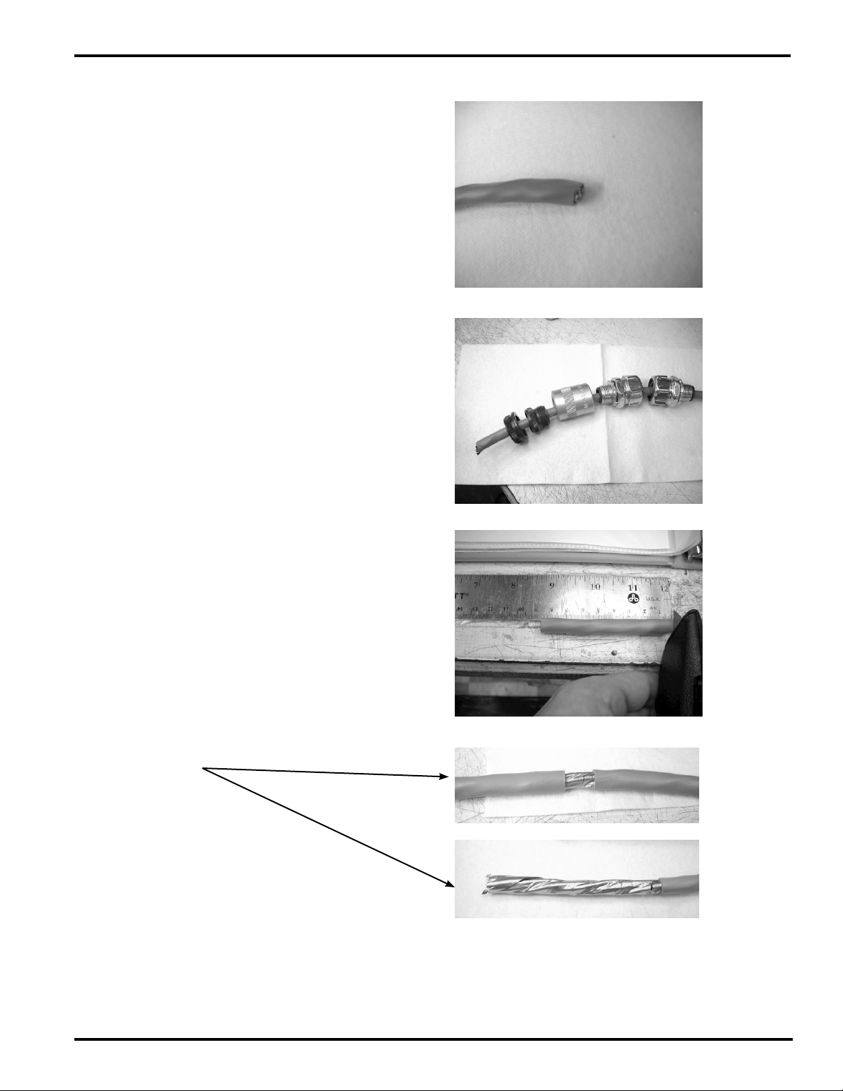
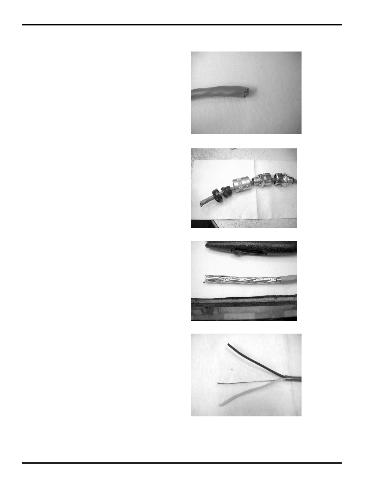
1. Cut cable length accordingly.
2. Slide the components over the cable as shown
* Flexible conduct not shown, to be provided by customer.
3
3. Score the outer cable jacket at 85mm.
4. Remove the outer cable insulation to expose the
foil shielding.
IM 11M12WZ-01-E
Page 4
4
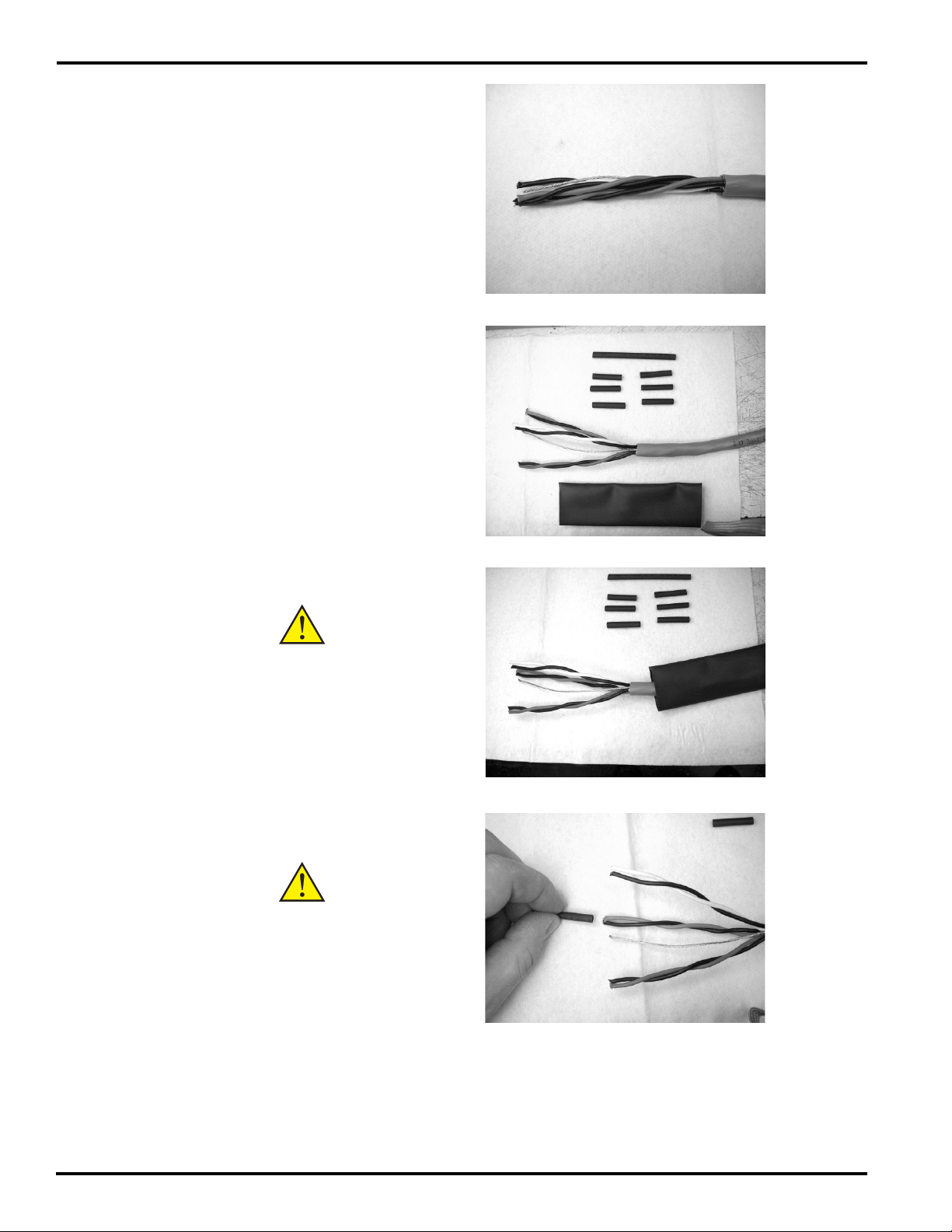
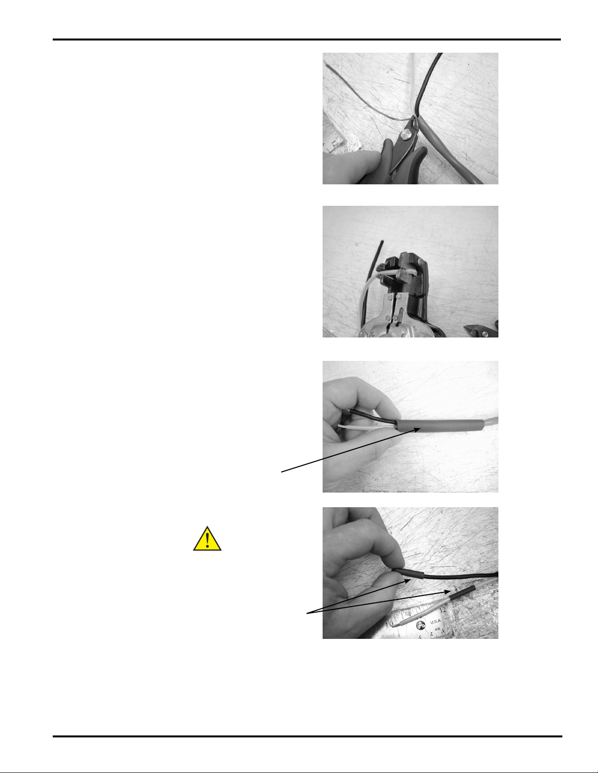
5. Remove foil shield to expose conductors.
6. Prepare 1” sections of 15mm heat shrink for application.
7. Slide heat shrink over cable.
CAUTION
Do not apply heat
at this time.
8. Push 1” sections of (15mm) heat shrink over individual conductors.
CAUTION
Do not apply heat
at this time.
IM 11M12WZ-01-E
Page 5
9. Push 3” section of (15mm) heat shrink over
ground wire.
Example of cable preparation.
5
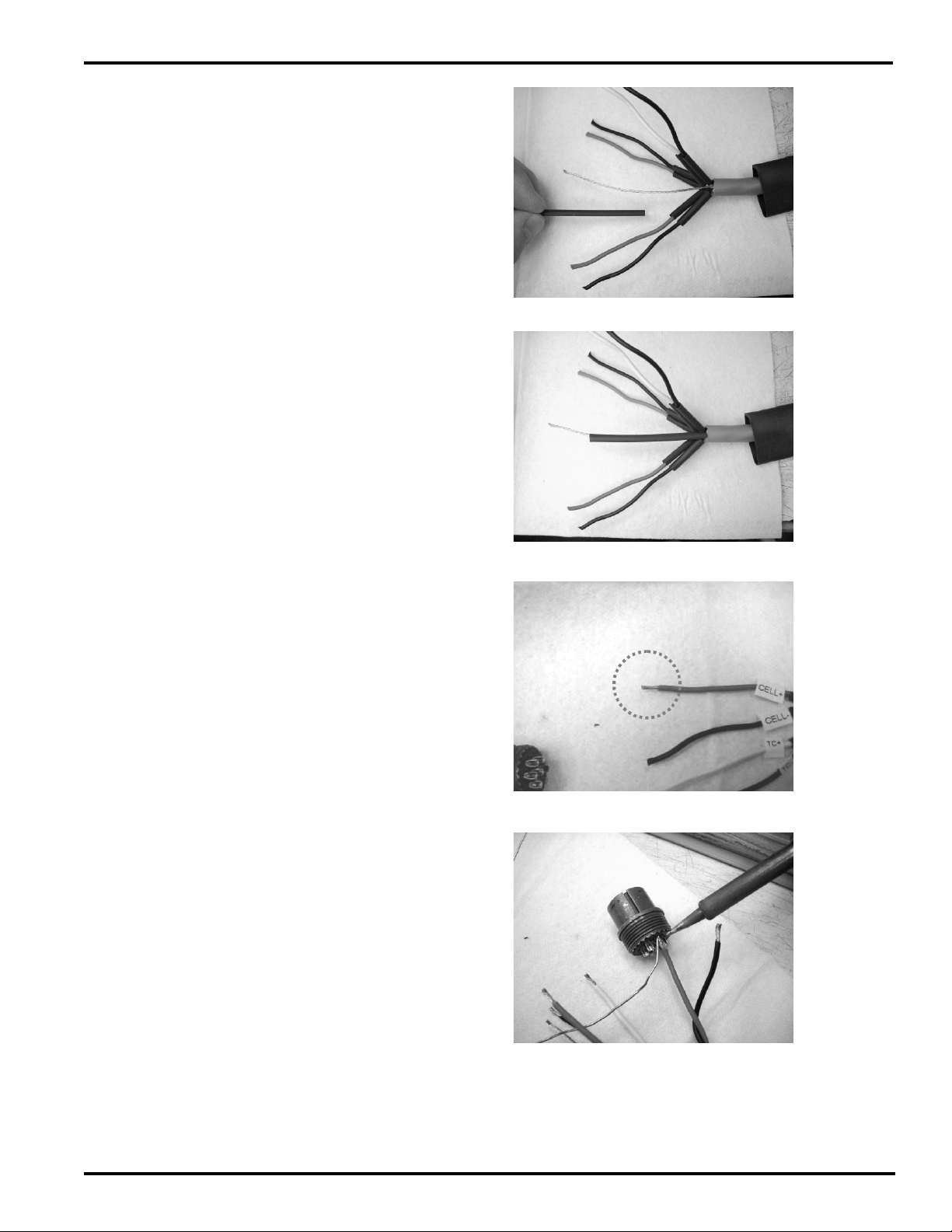
10. Strip approximately 5mm of insulation from
conductors.
11. Solder the conductors to the Amphenol connector. Solder joints should be neat, clean and
not touching each other.
IM 11M12WZ-01-E
Page 6

6
Soldering view for WZ cable
REDCELL +
A
BLACKCELL -B
WHITETC +C
BLACKTC -D
GREENCJ +E
BLACKCJ -F
SILVERGROUNDG
Ensure notch is in between A & F on the 7 pin connector.
Ensure notch is in between A & C on the 3 pin connector.
12. Solder joints should be neat, clean and not
touching each other.
CJ
+
CJ
_
E
TC
CELL
+
F
G
D
_
A
CELL
B
C
TC
_
+
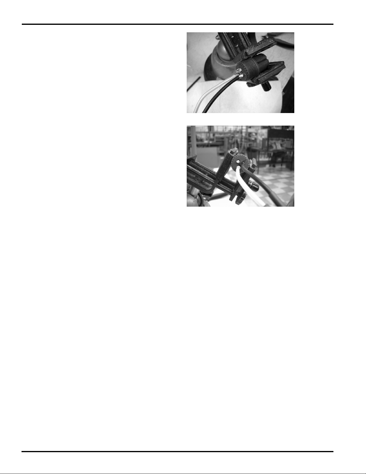
CAUTION
Do not apply excessive heat. Prolonged
exposure to heat gun will cause the
shrink tubing to split and fray.
13. Slide the heat shrink over the soldered connections, apply heat and seal the connections.
IM 11M12WZ-01-E
Page 7

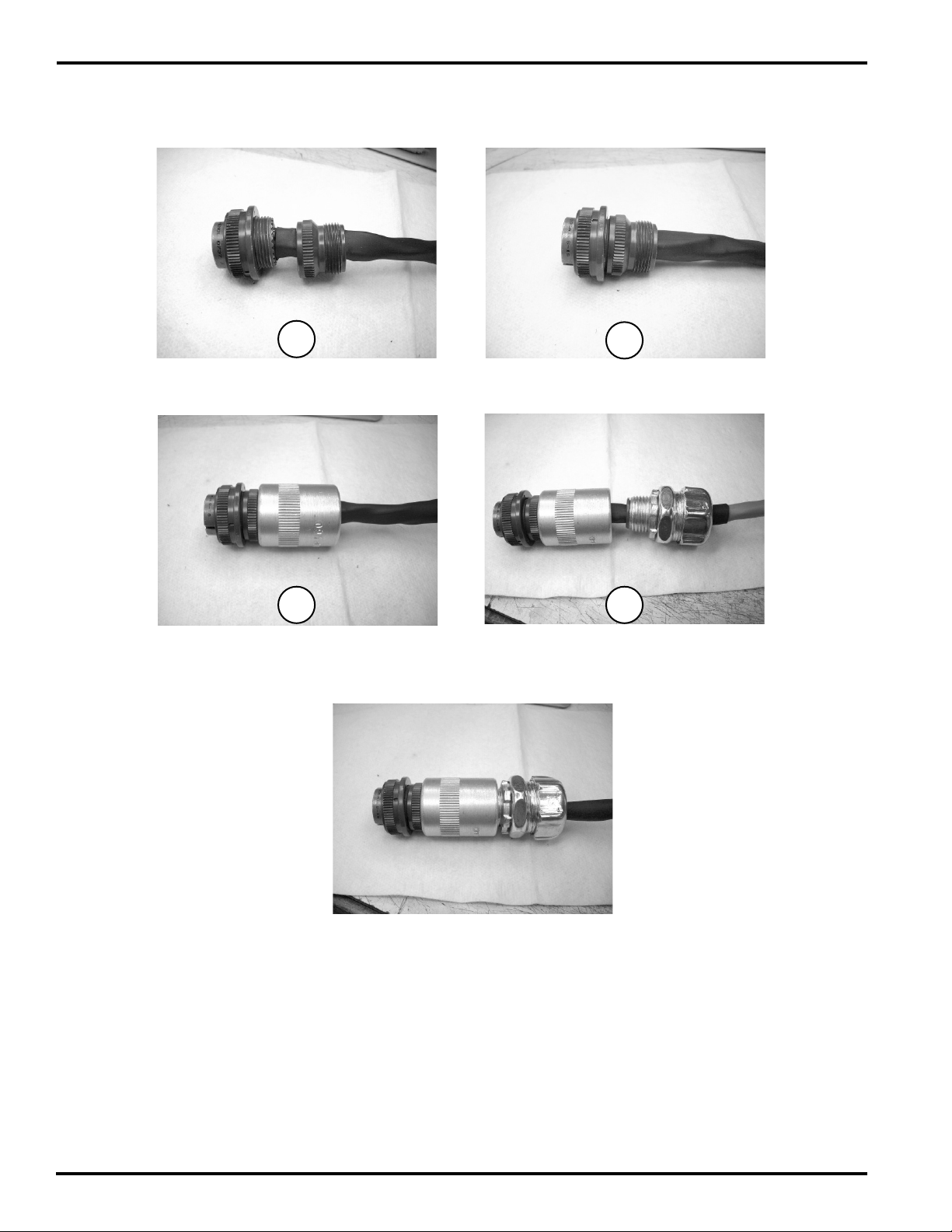
14. Slide the larger heat shrink tube and apply heat.
CAUTION
Do not apply excessive heat. Prolonged
exposure to heat gun will cause the
shrink tubing to split and fray.
15. Assemble backshell.
7
IM 11M12WZ-01-E
Page 8
8
Connector & Backshell Assembly
1
2
3 4
Final Connector Assembly
IM 11M12WZ-01-E
Page 9

2. 3 Pin Amphenol Connector & High Temperature
Cable
Parts Listing for 3 pin Amphenol Connector
QTYUnit IssueNomenclatureItem No.
3EACrimps1
2EAFlex Conduit Connector2
9
3
Connector
7
Connector
*Items 1 & 6 will be installed on the Analyzer side. Flexible conduct not shown, to be provided by customer.
Item 7
(backshell)
Item 3
Item 2
1EAAmphenol to Conduit
1EA100mm Heat Shrink4
3EA15mm Heat Shrink5
3EAWire labels6
1EAThree (3) pin Amphenol
*Flexible conduct not shown.
IM 11M12WZ-01-E
Page 10
10
WZ-H Connector Assembly
1. Cut cable to length.
2. Slide connector parts over cut cable (as shown):
* Flexible conduct not shown, to be provided by customer.
3. Remove 85mm of outer cable jacket.
4. Remove foil shield to outer cable jacket.
IM 11M12WZ-01-E
Page 11
5. Trim ground wire back to outer cable jacket.
6. Strip 5mm of insulation from each conductor.
11
7. Slide heat shrink over cable, and conductors.
Item 4
CAUTION
Do not apply heat
at this time.
Item 5
IM 11M12WZ-01-E
Page 12
12
8. Solder conductors to the contacts on the backside of the connector*.
* Refer to solder diagram below.
IM 11M12WZ-01-E
Page 13

Ensure notch is in between A & C on the 3 pin connector
13
HEATER 7DO NOT USE
BLACKHEATER 7A
HEATER 8B
CLEAR/ OR
WHITE
NONEC
9. Slide heat shrink to cover solder connection and
contacts. Apply heat.
CAUTION
Do not apply excessive heat. Prolonged
exposure to heat gun will cause the
shrink tubing to split and fray.
CA
B
HEATER 8
10. Slide outer heat shrink into place around conductors & contacts. Apply heat.
IM 11M12WZ-01-E
Page 14

14
11. Slide connector and backshell into place. Assemble connector as follows:
12. Slide flex backshell and flex conduit adapter
onto connector assembly.
13. Final product.
*Flex conduit not shown.
IM 11M12WZ-01-E
Page 15
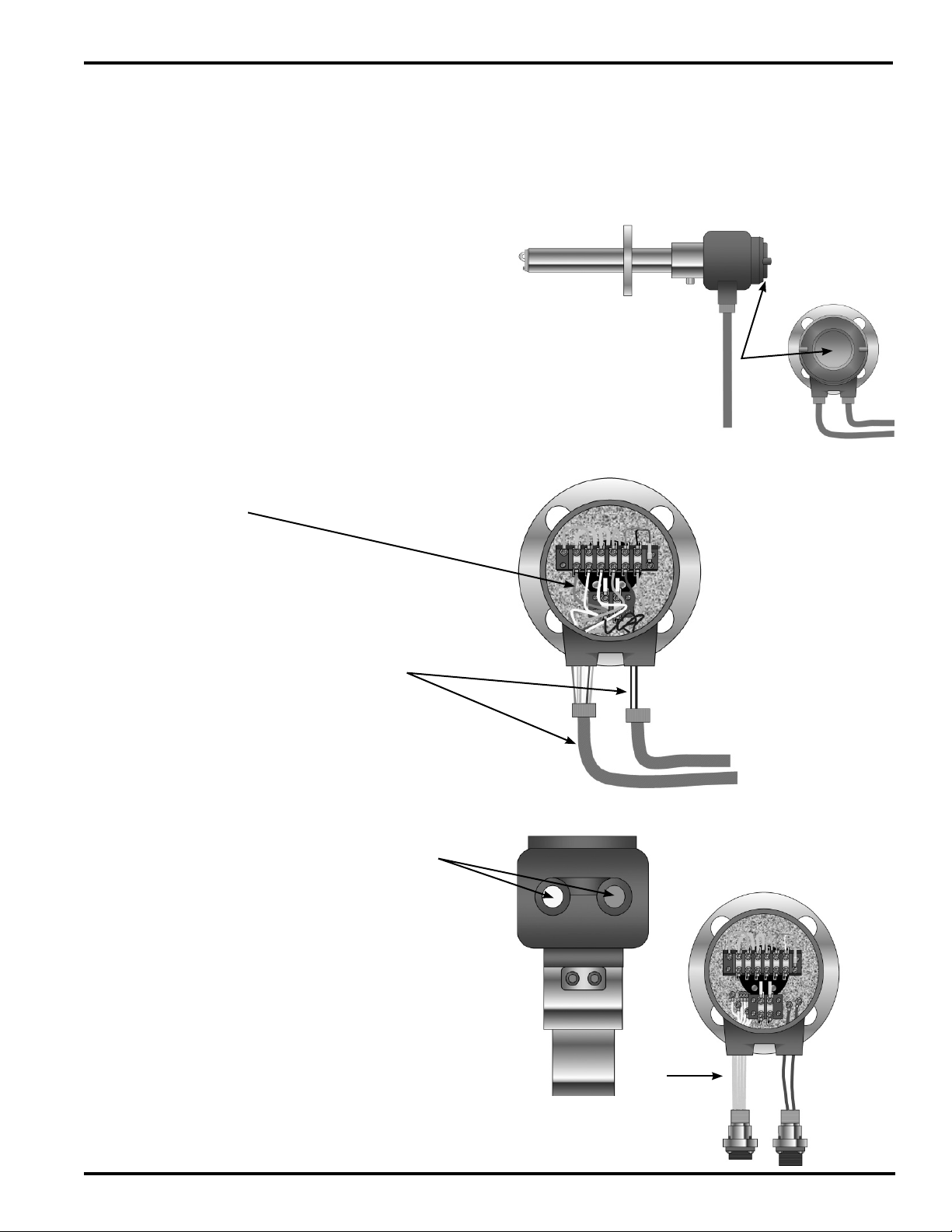
3. M1234PT-A & M1234PU-A Installation Guide
* Not included with /QF option.
1. Remove housing cover.
15
2. Disconnect leads.
3. Remove cable glands, cable and conduit
(if applicable)
4. Route conductors through electrical ports
(as shown)
IM 11M12WZ-01-E
Page 16

16
5. Attach leads as shown.
6. Replace housing cover and connect QF
connectors.
Yellow
123456
Blue
78
IM 11M12WZ-01-E
 Loading...