


WT3000
WT3000 Manual, Vol 3/3
Precision Power Analyzer
Expansion Function
IM 760301-51E
7th Edition

Note
Thank you for purchasing the WT3000 Precision Power Analyzer.
This Expansion Function User’s Manual contains useful information about the operating
procedures and lists the handling precautions of the expansion functions. To ensure
correct use, please read this manual thoroughly before beginning operation. After reading
the manual, keep it in a convenient location for quick reference whenever a question
arises during operation.
Three manuals, including this one, are provided as manuals for the WT3000. Please
read all of them.
Manual Title Manual No. Description
WT3000 Precision Power Analyzer
User’s Manual
(Vol 1/3)
WT3000 Precision Power Analyzer
Communication Interface
User’s Manual (CD-ROM)
(Vol 2/3)
WT3000 Precision Power Analyzer
Expansion Function
User’s Manual
(Vol 3/3)
IM 760301-51E Explains all functions and procedures
of the WT3000 excluding the expansion
functions and communication functions.
IM 760301-17E Explains the functions for controlling
the WT3000 using communication
commands.
IM 760301-51E This manual. Explains the expansion
functions (motor evaluation function
and options) of the WT3000 and their
operating procedures.
• The contents of this manual are subject to change without prior notice as a result of
continuing improvements to the instrument’s performance and functions. The figures
given in this manual may differ from those that actually appear on your screen.
•
Every effort has been made in the preparation of this manual t
o ensure the accuracy
of its contents. However, should you have any questions or find any errors, please
contact your nearest YOKOGAWA dealer.
• Copying or reproducing all or any part of the contents of this manual without the
permission of
• The TCP/IP
Yokogawa Electric Corporation is strictly prohibited.
software of this product and the document concerning the TCP/IP
software have been developed/created by YOKOGAWA based on the BSD Networking
Software, Release 1 that has been licensed from the University of California.
Trademarks
• Microsoft, Internet Explorer, MS-DOS, Windows, Windows NT, and Windows XP are
either registered trademarks or trademarks of Microsoft Corporation in the United
States and/or other countries.
•
Adobe, Acrobat, and PostScript are trademarks of
• For purposes of this manual, the ® and TM symbols do not accompany their
respective registered trademark names or trademark names.
• Other company and product names are registered trademarks or trademarks of their
respective holders.
Revisions
• 1st Edition December 2004
• 2nd Edition June 2005
• 3rd Edition January 2006
• 4th Edition December 2006
• 5th Edition March 2007
• 6th Edition May 2009
• 7th Edition February 2014
7th Edition: Februray 2014 (YMI)
All Rights Reserved, Copyright © 2004 Yokogawa Electric Corporation
All Rights Reserved, Copyright © 2014 Yokogawa Meters & Instruments Corporation
IM 760301-51E
Adobe Systems Incorporated.
i

Safety Precautions
This instrument is an IEC safety class 01 instrument (provided with a terminal for
protective earth grounding).
The general safety precautions described in the User’s Manual IM760301-01E and
this manual (IM760301-51E) must be observed during all phases of operation. If the
instrument is used in a manner not specified in these manuals, the protection provided
by the instrument may be impaired. Yokogawa Electric Corporation assumes no liability
for the customer’s failure to comply with these requirements.
ii
IM 760301-51E

Conventions Used in This Manual
Safety Markings
The following markings are used in this manual.
Improper handling or use can lead to injury to the user or damage to
the instrument. This symbol appears on the instrument to indicate that
the user must refer to the user’s manual for special instructions. The
same symbol appears in the corresponding place in the user’s manual
to identify those instructions. In the manual, the symbol is used in
conjunction with the word “WARNING” or “CAUTION.”
Subheadings
WARNING
CAUTION
Calls attention to information that is important for proper operation of
Note
On pages that describe operating procedures, the following symbols, displayed
characters, and terminology are used to distinguish the procedures from their
explanations:
Procedure
Explanation
Calls attention to actions or conditions that could cause serious or
fatal injury to the user, and precautions that can be taken to prevent
such occurrences.
Calls attentions to actions or conditions that could cause light injury to
the user or damage to the instrument or user’s data, and precautions
that can be taken to prevent such occurrences.
the instrument.
Follow the numbered steps. All procedures are written with
inexperienced users in mind; experienced users may not need to
carry out all the steps.
This subsection describes the setting parameters and the limitations
on the procedures.
Unit
IM 760301-51E
Displayed Characters and Terminology Used in the Procedural Explanations
Panel Keys and Soft keys
Bold characters used in the procedural explanations indicate characters that are marked on the
panel keys or the characters of the soft keys or menus displayed on the screen.
SHIFT+Panel Key
SHIFT+key means you will press the SHIFT key to turn ON the SHIFT key followed by the
operation key. The setup menu marked in purple below the panel key that you pressed appears on
the screen.
k Denotes 1000. Example: 12 kg, 100 kHz
K Denotes 1024. Example: 459 KB (file data size)
iii

Contents
Safety Precautions ............................................................................................................................ii
Conventions Used in This Manual ................................................................................................... iii
Chapter 1 Motor Evaluation Function (Motor Version)
1.1 Names and Functions of Parts of the Motor Evaluation Function .................................... 1-1
1.2 Applying Signals of Rotating Speed and Torque .............................................................. 1-2
1.3 Selecting the Type of the Revolution and Torque Signals ................................................ 1-4
1.4 Selecting the Analog Range .............................................................................................
1.5 Selecting the Line Filter and Synchronization Source .................................................... 1-10
1.6 Setting the Pulse Range, Pulse Count, and Pulse Rating .............................................. 1-12
1.7 Setting the Scaling Factor and Unit ................................................................................ 1-17
1.8 Setting the Motor and Frequency Measurement Source fo
Speed and Slip ......................................................................................................
1.9
1.10 Specications
Chapter 2 Built-in Printer (Option)
2.1 Names and Functions of Parts of the Built-in Printer ....................................................... 2-1
2.2 Loading the Roll Paper and Feeding the Paper ............................................................... 2-2
2.3 Printing Screen Images on the Built-in Printer ................................................................. 2-7
2.4 Printing Numeric Data Lists on the Built-in Printer ........................................................... 2-9
2.5 Auto Print
2.6 Built-in
ComputingtheMotorEfciencyandTotalEfciency...................................................... 1-24
oftheMotorEvaluationFunction ............................................................ 1-25
.......................................................................................................
PrinterSpecications .......................................................................................... 2-18
r Computing the Sync
................. 2-12
1-7
......... 1-21
Chapter 3 D/A Output and Remote Control (Option)
3.1 Part Names and Functions of D/A Output ........................................................................ 3-1
3.2 Setting the D/A Output ...................................................................................................... 3-3
3.3 Setting the D/A Zoom ..................................................................................................... 3-10
3.4 Remote Control .............................................................................................................. 3-12
3.5 D/AOutputandRemoteControlSpecications ............................................................. 3-14
Chapter 4 RGB Video Signal (VGA) Output (Option)
4.1 Names and Functions of the Parts of the RGB Video Signal (VGA) Output .................... 4-1
4.2 RGBVideoSignal(VGA)OutputSpecications............................................................... 4-2
Chapter 5 Ethernet Communications (Option)
5.1 Connecting to the Network ............................................................................................... 5-1
5.2 Setting TCP/IP .................................................................................................................. 5-2
5.3 Saving Setup, Waveform Display
(FTP Client Function) ......................................................................................................
Printing Screen Images on a Network Printer ................................................................ 5-12
5.4
5.5 Sending E-mail ...............................................................................................................
5.6 Accessing the WT3000 from a PC or Workstation (FTP
5.7 Setting of the T
5.8
5.9 Setting the FTP Passive Mode and LPR/SMTP Timeout ............................................... 5-26
5.10 EthernetInterfaceSpecications .................................................................................... 5-28
Checking the Ethernet Communication Function (Option) Availability and
MAC Address ..................................................................................................................... 5-25
ime Difference from GMT or SNTP ........................................................ 5-23
, Numeric, and Image Data to the FTP Server
. 5-9
5-16
Server Function) ..................... 5-19
iv
IM 760301-51E

1
2
3
4
5
6
7
8
9
10
11
12
13
Index
Contents
Chapter 6 Delta Computation (Option)
6.1 Delta Computation Function ............................................................................................. 6-1
6.2 Setting the Delta Computation ......................................................................................... 6-2
6.3 Determination of Delta Computation ................................................................................ 6-5
6.4 Delta
ComputationSpecications .................................................................................... 6-6
Chapter 7 Harmonic Measurement in Normal Measurement Mode (Option)
7.1 Harmonic Measurement Function .................................................................................... 7-1
7.2 Setting the Measurement Mode and Displaying Numeric Data ...................................... 7-10
7.3 Setting the Number of Displayed Items, Page Scrolling the Display ..............................
7.4 Changing the Displayed Items of Numeric Data ............................................................ 7-16
7.5 Selecting the PLL Source ............................................................................................... 7-22
7.6 Setting the Measured Order ........................................................................................... 7-25
7.7 Selecting the Distortion Factor Equation ........................................................................ 7-27
7.8 Setting the
7.9 Displaying the Bar Graph and Making Cursor Measurements
7.10 Displaying Vectors
7.11 Harmonic
Anti-Aliasing Filter ........................................................................................
....................................... 7-30
.......................................................................................................... 7-35
MeasurementSpecications .......................................................................... 7-38
7-12
7-28
Chapter 8 Wide Bandwidth Harmonic Measurement (Option)
8.1 Wide Bandwidth Harmonic Measurement Function ......................................................... 8-1
8.2 Various Settings Related to Wide Bandwidth Harmonic Measurement ............................ 8-2
8.3 Selecting the Wide Bandwidth Harmonic Measurement Mode and
Displaying Numeric Data ..................................................................................................
8.4
Turning ON/OFF the
8.5 Wide
BandwidthHarmonicMeasurementSpecications ................................................. 8-6
Timeout Warning Display of the PLL Lock ...................................... 8-5
8-3
Chapter 9 IEC Harmonic Measurement (Option)
9.1 IEC Harmonic Measurement Function ............................................................................. 9-1
9.2 Various Settings Related to IEC Harmonic Measurement ................................................ 9-5
9.3 Selecting the IEC Harmonic Measurement Mode ............................................................ 9-6
9.4 Selecting the Measured Source ....................................................................................... 9-7
9.5 Selecting the V
9.6 IEC
HarmonicMeasurementSpecications ................................................................... 9-10
oltage/Current Grouping ...........................................................................
Chapter 10 Waveform Computation (Option)
10.1 Waveform Computation Function ................................................................................... 10-1
10.2 Various Settings Related to Waveform Computation ..................................................... 10-3
10.3 Setting the Waveform Computation Mode ......................................................................
10.4 Setting the Waveform Equation ......................................................................................
10.5 Setting the Scale, Unit, and Label of the Computed Waveform .....................................
10.6 Waveform
ComputationFunctionSpecications .......................................................... 10-13
9-8
10-4
10-5
10-9
IM 760301-51E
v

Contents
Chapter 11 FFT (Option)
11.1 FFT Function ...................................................................................................................11-1
11.2 Various Settings Related to FFT ......................................................................................11-4
11.3 Setting the FFT
11.4 Selecting the Power Spectrum to Be Displayed, Selecting
Setting the Label ......................................................................................................
11.5 Setting the Number of Computed Points and Time Window .........................................11-10
11.6 Setting the Display Range of the X-Axis (Frequency) and
the Y-Axis (Signal Amplitude) ........................................................................................11-12
1
1.7 Selecting the Display
11.8 Displaying the Power Spectrum on the Split Screen .....................................................
11.9 Cursor Measurement .....................................................................................................
11.10 FFT
FunctionSpecications ..........................................................................................11-20
Mode ......................................................................................................11-5
the FFT Source, and
the Scale Type of
Type of the Power Spectrum.......................................................11-14
Chapter 12 Voltage Fluctuation and Flicker Measurement (Option)
12.1 Voltage Fluctuation and Flicker Measurement Function ................................................ 12-1
12.2 Setting the Voltage Fluctuation and Flicker Measurement Mode ................................... 12-6
12.3 Setting the Measurement Conditions ............................................................................. 12-8
12.4 Setting the Judgement Conditions ............................................................................... 12-13
12.5 Executing the Normal V
12.6 Executing the Measurement of dmax Caused by Manual Switching ...........................
12.7 Voltage
FluctuationandFlickerMeasurementSpecications ...................................... 12-33
oltage Fluctuation and Flicker Me
asurement .......................... 12-18
.......1
11-16
11-17
12-25
1-7
Chapter 13 Cycle-by-Cycle Measurement (Option)
13.1 Cycle-by-Cycle Measurement Function ......................................................................... 13-1
13.2 Setting the Cycle-by-Cycle Measurement Mode ............................................................ 13-4
13.3 Setting the Measurement Conditions ............................................................................. 13-6
13.4 Executing the Cycle-by-Cycle Measurement ............................................................... 13-13
13.5 Cycle-by-Cycle
MeasurementSpecications ............................................................... 13-19
Index
vi
IM 760301-51E
1
START STOP
REMOTE
CAL
SENSOR RATIO
MEASURING
RMS MEAN DC RMEAN
CURRENT RANGEVOLTAGE RANGE
MEASURING
RMS MEAN DC RMEAN
ALL
INPUT INFO.
MOTOR
SET
CURSOR NULL
MENU STORE SET
MENU
LOWER ITEM LOWER FORM ALLUSER SET
DISPLAY
ITEM & ELEMENT
2
3 4
COMPEN
ESC
ELEMENT
ELEMENT
1
WIRING
MODE AUTO MODE AUTO
EXT SENSOR
RESET SET
PAGE PAGE
SCALING
HRM SET
MEASURE
SYNC SOURCE
AVG
LINE FILTER
FREQ
FILTER
FILE
PRINT
MISC
STORE
IMAGE SAVE
HELP
NUMERIC WAVE
OTHERS
ITEM
FORM
U / I / P
WP/q/
TIME
USER
ELEMENT
UPDATE
RATE
HOLD
SINGLE
INTEG
LOCAL
SHIFT
YOKOGAWA
WT3 00 0
PRECI SIO N PO WER ANA LYZ ER
MOTOR VERS ION
SHIFT+SCALING (MOTOR SET) key (motor version)
Sets items that are required in the motor evaluation such as torque,
number of rotations, and motor output.
ELEMENT
VOLTAGE
±
1000V
MAX
1000V
MAX
±
CURRENT
1
30A
MAX
EXT
CAT II
ALL TERMINALS
1000V MAX TO
ELEMENT
VOLTAGE
±
1000V
MAX
1000V
MAX
±
CURRENT
2
30A
MAX
EXT
CAT II
ALL TERMINALS
1000V MAX TO
ELEMENT
VOLTAGE
±
1000V
MAX
1000V
MAX
±
CURRENT
3
30A
MAX
EXT EXT
CAT II
ALL TERMINALS
1000V MAX TO
ELEMENT
VOLTAGE
±
1000V
MAX
1000V
MAX
±
CURRENT
4
30A
MAX
CAT II
ALL TERMINALS
1000V MAX TO
TORQUE
± 20V MAX
± 20V MAX
SPEED
42V
pk MAX
D/A OUTPUT
VIDEO-OUT
(VGA)
GP-IB
(IEEE488)
SERIAL
(RS-232)
/ USB
EXT. CLK
ETHERNET
100BASE-TX
MEAS. START
100-240V AC 50/60Hz
200VA MAX
FUSE 250V T 6.3A
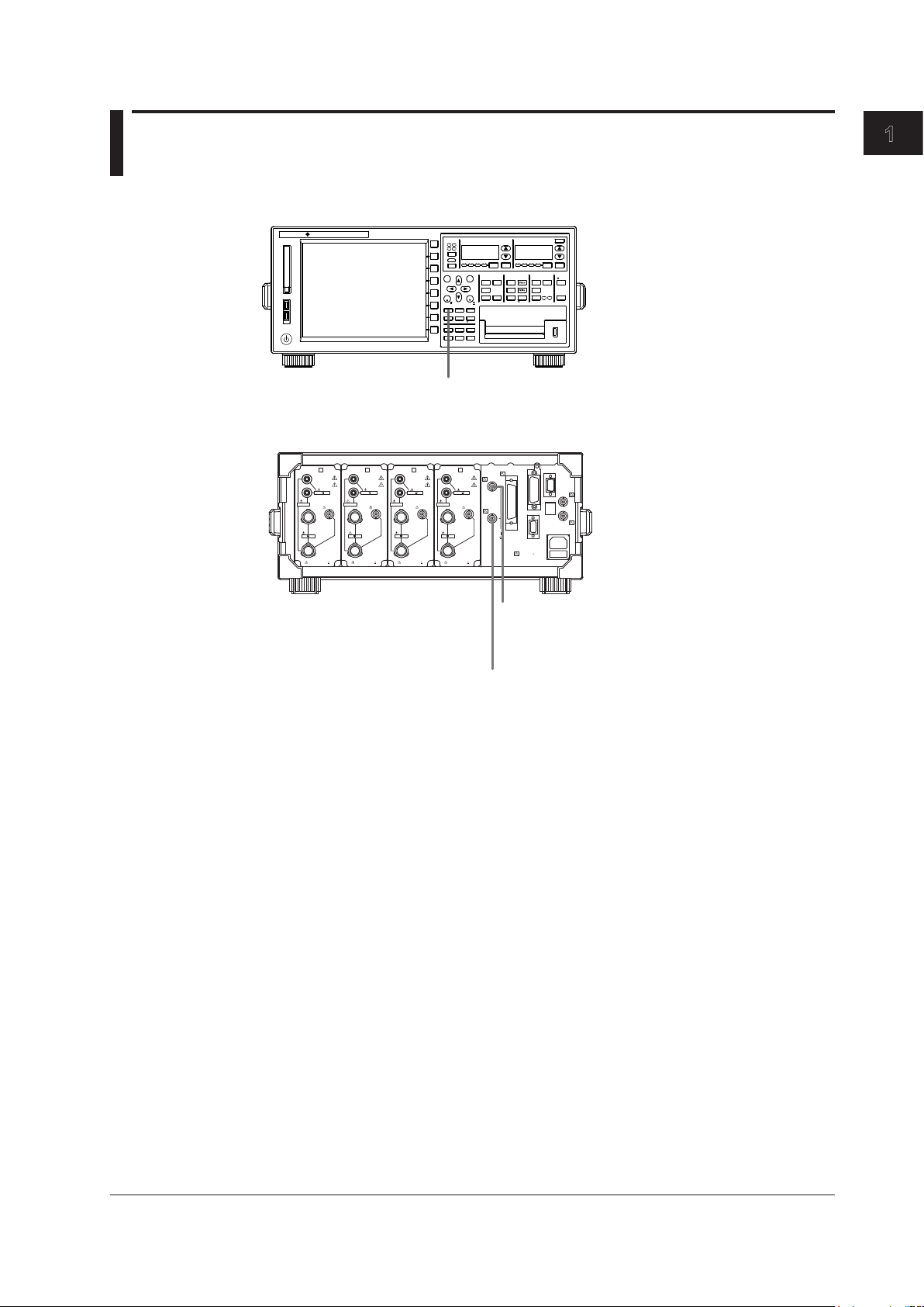
Torque signal input connector (TORQUE)
(motor version)
Receives signals from torque meters when evaluating
motors.
Revolution signal input connector (SPEED)
(motor version)
Receives signals from revolution sensors when evaluating
motors.
Chapter 1
Motor Evaluation Function (Motor Version)
1.1 Names and Functions of Parts of the Motor Evaluation Function
Front Panel
Rear Panel
Motor Evaluation Function (Motor Version)
Functional Description
By using the motor evaluation function (motor version), the rotating speed, torque, and
output of a motor can be determined from the signal that is proportional to the rotating
speed of the motor, and the signal received from a torque meter, which is proportional to
the motor’s torque. The signal applied from the revolution sensor or torque meter to the
WT3000 can be selected from analog signal (DC voltage) or pulse signal. In addition,
the synchronous speed and slip of a motor can be determined by setting the motor’s
number of poles. Furthermore, the active power and frequency that are measured by the
WT3000 and the motor output can be used to compute the motor efficiency and the total
efficiency.
Types of Measurement Functions
Measurement functions consists of Speed (rotating speed), Torque, Pm (motor output
or mechanical power), SyncSp (synchronous speed), and Slip. For details on the
Limitations by Measurement Modes
IM 760301-51E
determination of the measurement functions, see section 1.10. Set equations for the
motor
the procedures in section 5.7 in the User’s Manual IM760301-01E.
Measurement functions of the motor evaluation function cannot be measured in wide
bandwidth harmonic measurement, IEC harmonics measurement, voltage fluctuation and
flicker measurement, and cycle-by-cycle measurement modes.
ficiency((Pm)/(PΣA)×100)andtotalefficiency((Pm)/(PΣB)×100)accordingto
ef
1-1

1-2
IM 760301-51E
1.2 Applying Signals of Rotating Speed and Torque
SPEED
20V MAX
CAUTION
Applying a voltage exceeding the maximum allowable input to the revolution signal
input connector (SPEED) or torque signal input connector (TORQUE) can damage
the instrument.
Revolution Signal Input Connector (SPEED)
Input the signal output from the revolution sensor (a DC voltage (analog signal) or a
pulse signal that is proportional to the rotating speed of the motor) according to the
following specifications.
• DC Voltage (Analog Input)
Item Specifications
Connector type
Input range
Effective input range
Input resistance
Maximum allowable input
Continuous maximum common mode voltage
Isolated BNC connector
1 V, 2 V, 5 V, 10 V, and 20 V
0% to ±110% of the measurement range
Approx.
±22 V
±42 Vpeak or less
• Pulse Input
Item Specifications
Connector type
Frequency range
Amplitude input range
Effective amplitude
Input waveform
Input resistance
Continuous maximum common mode voltage
Isolated BNC connector
2 Hz to 200 kHz
±12 Vpeak
1 V (peak to peak) or more
50% duty ratio rectangular wave
Approx.
±42 Vpeak or less
1
1
MΩ
MΩ

1
Torque Signal Input Connector (TORQUE)
TORQUE
20V MAX
Input the signal output from the torque meter (a DC voltage (analog or pulse signal) that
is proportional to the torque of the motor) according to the following specifications.
• DC Voltage (Analog Input)
Item Specifications
Connector type
Input range
Effective input range
Input resistance
Maximum allowable input
Continuous maximum common mode voltage
• Pulse Input
Item Specifications
Connector type
Frequency range
Amplitude input range
Effective amplitude
Input waveform
Input resistance
Continuous maximum common mode voltage
1.2 Applying Signals of Rotating Speed and Torque
Isolated BNC connector
1 V, 2 V, 5 V, 10 V, and 20 V
0% to ±110% of the measurement range
Approx.
±22 V
±42 Vpeak or less
Isolated BNC connector
2 Hz to 200 kHz
±12 Vpeak
1 V (peak to peak) or more
50% duty ratio rectangular wave
Approx.
±42 Vpeak or less
MΩ
1
1MΩ
Motor Evaluation Function (Motor Version)
IM 760301-51E
1-3
1-4
IM 760301-51E
1.3 Selecting the Type of the Revolution and
START STOP
REMOTE
CAL
MOTOR
SET
CURSOR NULL
MENU STORE SET
MENU
LOWER ITEM LOWER FORM ALLUSER SET
DISPLAY
ITEM & ELEMENT
RESET SET
PAGE PAGE
SCALING
HRM SET
MEASURE
SYNC SOURCE
AVG
LINE FILTER
FREQ
FILTER
FILE
PRINT
MISC
STORE
IMAGE SAVE
HELP
NUMERIC
WAVE
OTHERS
ITEM
FORM
U / I / P
WP/q/
TIME
USER
ELEMENT
UPDATE
RATE
HOLD
SINGLE
INTEG
LOCAL
SHIFT
Cursor keys
To exit the menu during operation, press ESC located above the
soft keys.
In the procedural explanation below, the phrase “press the cursor
keys” may be used. This phrase refers to the procedures for
selecting items and entering values and character strings. For
details on the procedures, see section 3.14 in the User’s Manual
IM760301-01E.
Torque Signals
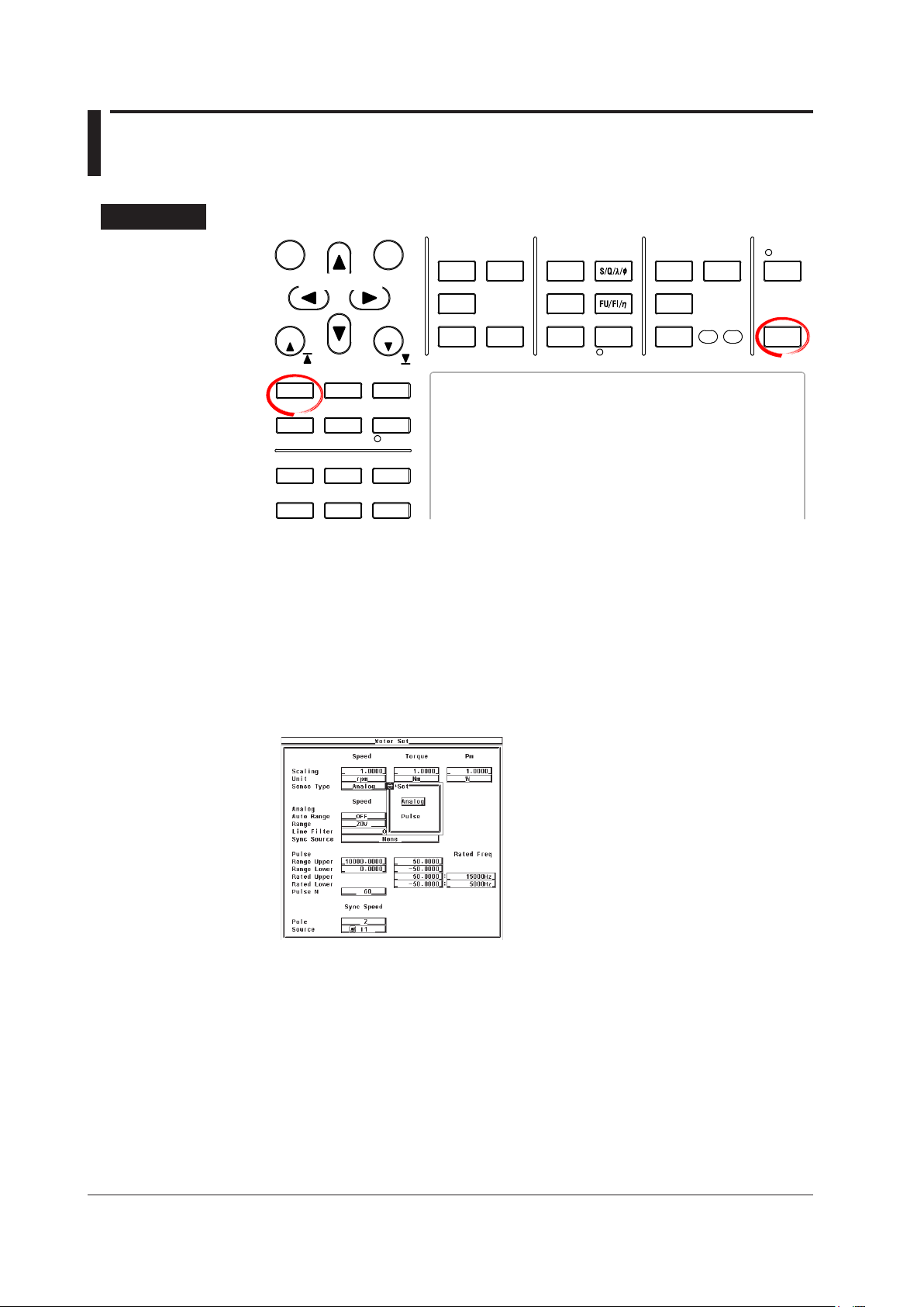
Procedure
Press SHIFT+SCALING (MOTOR SET) to display the Motor Set dialog box.
1.
• Selecting the Revolution Signal Type
Press the cursor keys to select the Sense Type under Speed.
2.
Press SET. A signal type selection box appears.
3.
Press the cursor keys to select Analog or Pulse.
4.
Press SET to confirm the signal type.
5.
1
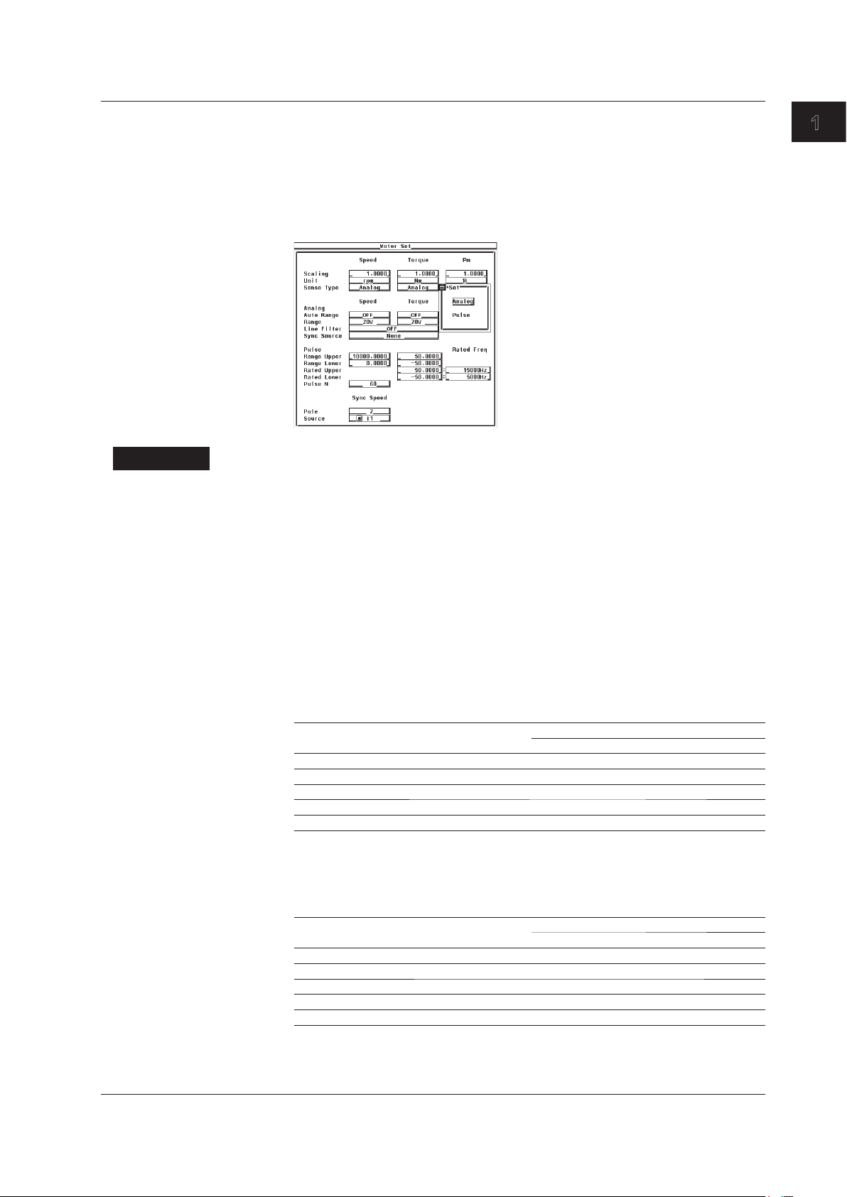
• Selecting the Torque Signal Type
Explanation
• Selecting the Signal Type
The signal applied from the revolution sensor or torque meter to the WT3000 can be
• Analog
•
1.3 Selecting the Type of the Revolution and Torque Signals
Press the cursor keys to select the Sense Type under Torque.
2.
Press SET. A signal type selection box appears.
3.
Press the cursor keys to select Analog or Pulse.
4.
Press SET to confirm the signal type.
5.
selected from the following two types.
Select this when the signal type is a DC voltage (analog signal).
Pulse
Select this when the signal type is a pulse signal.
Motor Evaluation Function (Motor Version)
• Signal Type and Setup Items
Some of the settings described in the subsequent sections are not required depending
on the signal type as described below.
• Settings Related to the Revolution Signal Type
Revolution Signal Type
Analog Pulse
Analog range (section 1.4) Required Not required
Line filter (section 1.5) Required Not required
Synchronization source (section 1.5) Required Recommended*
Pulse range (section 1.6) Not required Required
Pulse count per revolution (section 1.6) Not required Required
*
Measurement is possible using None (default), but it is recommended that you specify the
setting to improve the measurement accuracy
1.5.
• Settings Related to the Torque Signal Type
Analog range (section 1.4) Required Not required
Line filter (section 1.5) Required Not required
Synchronization source (section 1.5) Required Recommended*
Pulse range (section 1.6) Not required Required
Pulse rating (section 1.6) Not required Required
*
Measurement is possible using None (default), but it is recommended that you specify the
setting to improve the measurement accuracy
1.5.
. For details, see the explanation in section
Torque Signal Type
Analog Pulse
. For details, see the explanation in section
IM 760301-51E
1-5

1-6
IM 760301-51E
1.3 Selecting the Type of the Revolution and Torque Signals
• Common Settings Not Dependent on the Signal Type
• Motor’s number of poles and frequency measurement source (section 1.7)
• Scaling factor and unit (section 1.8)
1
1.4 Selecting the Analog Range
START STOP
REMOTE
CAL
MOTOR
SET
CURSOR NULL
MENU STORE SET
MENU
LOWER ITEM LOWER FORM ALLUSER SET
DISPLAY
ITEM & ELEMENT
RESET SET
PAGE PAGE
SCALING
HRM SET
MEASURE
SYNC SOURCE
AVG
LINE FILTER
FREQ
FILTER
FILE
PRINT
MISC
STORE
IMAGE SAVE
HELP
NUMERIC
WAVE
OTHERS
ITEM
FORM
U / I / P
WP/q/
TIME
USER
ELEMENT
UPDATE
RATE
HOLD
SINGLE
INTEG
LOCAL
SHIFT
Cursor keys
To exit the menu during operation, press ESC located above the
soft keys.
In the procedural explanation below, the phrase “press the cursor
keys” may be used. This phrase refers to the procedures for
selecting items and entering values and character strings. For
details on the procedures, see section 3.14 in the User’s Manual
IM760301-01E.
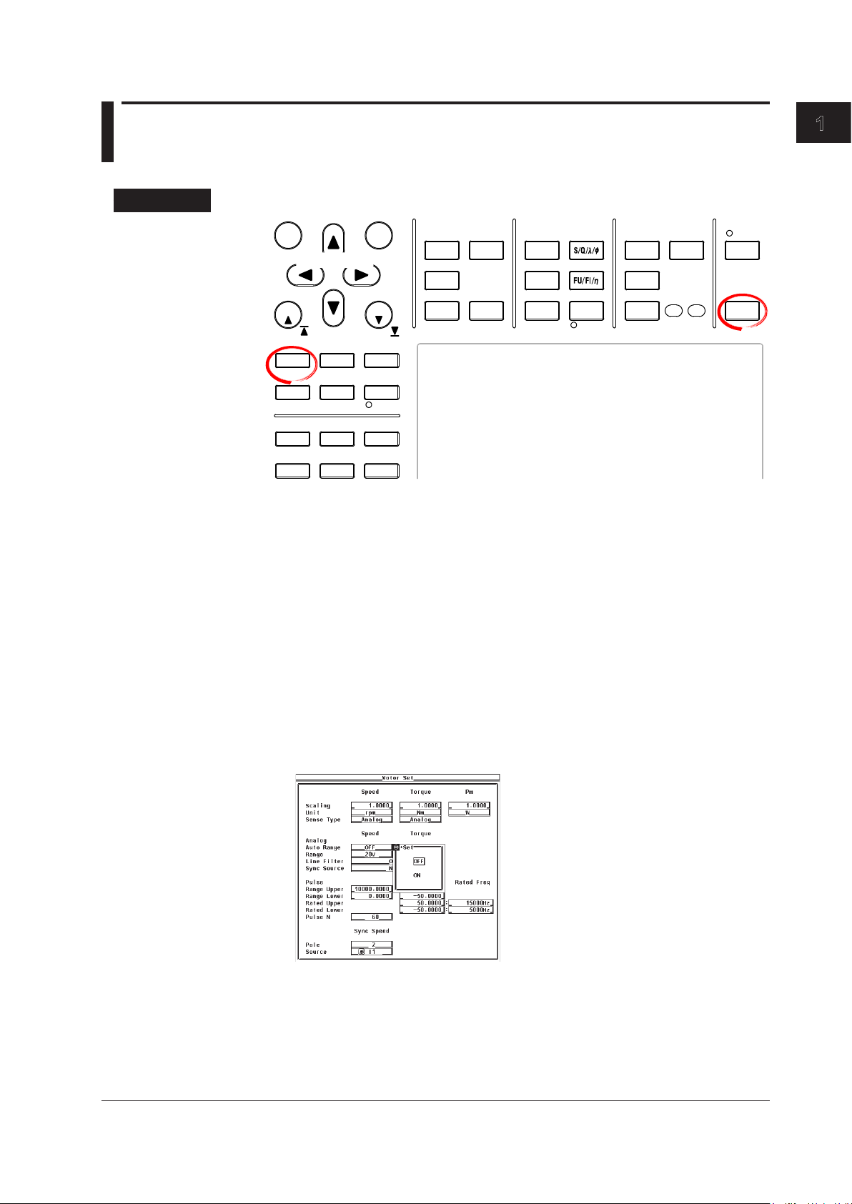
Procedure
The settings covered in this section apply to the case when the input signal type is set to
Analog. You do not have to specify the settings in this section if the input signal type is
set to Pulse.
Motor Evaluation Function (Motor Version)
• Selecting the Analog Input Range of the Revolution Signal
• Selecting Auto Range
Press SHIFT+SCALING (MOTOR SET) to display the Motor Set dialog box.
1.
Press the cursor keys to select Auto Range under Speed.
2.
Press SET. An auto range selection box appears.
3.
Press the cursor keys to select ON or OFF.
4.
Press SET to confirm the auto range setting.
5.
IM 760301-51E
1-7
1-8
IM 760301-51E
1.4 Selecting the Analog Range
• When Measuring Using a Fixed Range (When Auto Range Is Set to OFF)
6.
7.
8.
9.
• Selecting the Analog Input Range of the Torque Signal
• Selecting Auto Range
2.
3.
4.
5.
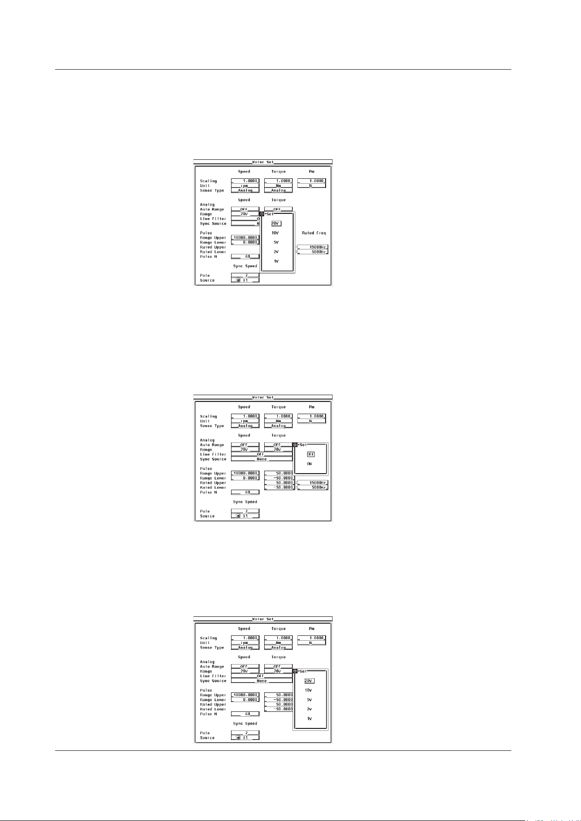
Press the cursor keys to select Range under Speed.
Press SET. An input range selection box appears.
Press the cursor keys to select a value between 20 V to 1 V.
Press SET to confirm the input range.
Press the cursor keys to select Auto Range under Torque.
Press SET. An auto range selection box appears.
Press the cursor keys to select ON or OFF.
Press SET to confirm the auto range setting.
• When Measuring Using a Fixed Range (When Auto Range Is Set to OFF)
6.
7.
8.
9.
Press the cursor keys to select Range under Torque.
Press SET. An input range selection box appears.
Press the cursor keys to select a value between 20 V to 1 V.
Press SET to confirm the input range.

1
1.4 Selecting the Analog Range
Explanation
• Selecting the Input Range of the Revolution and Torque Signals
Two types of range settings are available: fixed and auto.
• Fixed Range
Select the input range from the following:
20 V, 10 V, 5 V, 2 V, or 1 V
•
Auto Range
Select ON for the auto range setting to enable auto range. The range changes
automatically depending on the amplitude of the input signal.
• Range Increase
• When the rotating speed or torque data exceeds 1
measurement range, the measurement range is increased.
• When the peak value of the input signal exceeds approximately 150% of the
measurement range, the range is increased.
• Range Decrease
Wh
en the rotating speed or torque data is less than 30% of the measurement range
and the peak value of the input signal is less than 125% of the next lower range,
the measurement range is decreased.
10% of the current
Motor Evaluation Function (Motor Version)
Note
When non-periodic pulse waveforms are applied during auto range, the range may not remain
constant. If this happens, use the fixed range setting.
IM 760301-51E
1-9
1-10
IM 760301-51E
1.5 Selecting the Line Filter and Synchronization
START STOP
REMOTE
CAL
MOTOR
SET
CURSOR NULL
MENU STORE SET
MENU
LOWER ITEM LOWER FORM ALLUSER SET
DISPLAY
ITEM & ELEMENT
RESET SET
PAGE PAGE
SCALING
HRM SET
MEASURE
SYNC SOURCE
AVG
LINE FILTER
FREQ
FILTER
FILE
PRINT
MISC
STORE
IMAGE SAVE
HELP
NUMERIC
WAVE
OTHERS
ITEM
FORM
U / I / P
WP/q/
TIME
USER
ELEMENT
UPDATE
RATE
HOLD
SINGLE
INTEG
LOCAL
SHIFT
Cursor keys
To exit the menu during operation, press ESC located above the
soft keys.
In the procedural explanation below, the phrase “press the cursor
keys” may be used. This phrase refers to the procedures for
selecting items and entering values and character strings. For
details on the procedures, see section 3.14 in the User’s Manual
IM760301-01E.
Source
Procedure
The settings covered in this section apply to the case when the input signal type is set to
Analog. You do not have to specify the settings in this section if the input signal type is
set to Pulse.
Press SHIFT+SCALING (MOTOR SET) to display the Motor Set dialog box.
1.
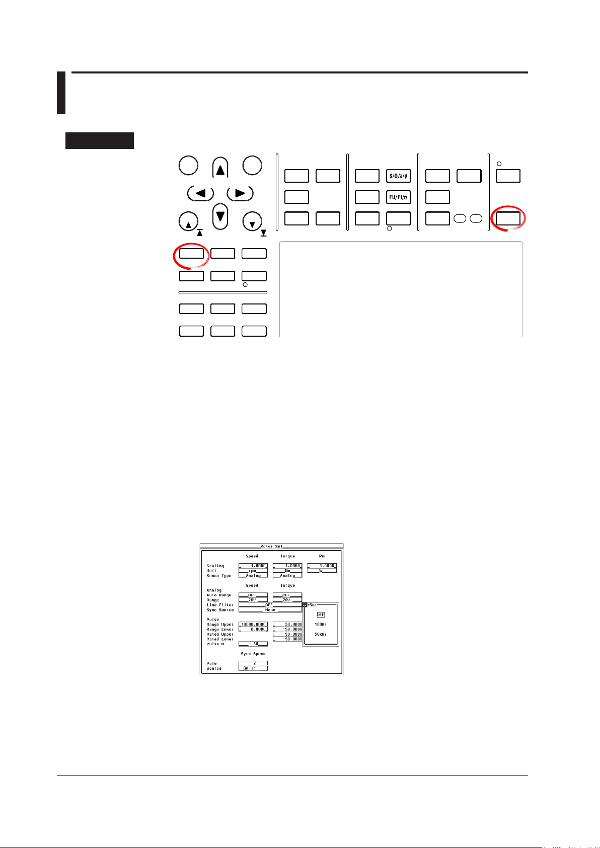
• Selecting the Line Filter
Press the cursor keys to select Line Filter.
2.
Press SET. A line filter selection box appears.
3.
Press the cursor keys to select a value between OFF and 50 kHz.
4.
Press SET to confirm the line filter. The same filter is set to both the revolution
5.
signal and the torque signal.
• Selecting the Synchronization Source
Press the cursor keys to select Sync Source.
2.
3.
4.
5.
Press SET. A synchronization source selection box appears.
Press the cursor keys to select any of the elements/wiring units starting with U1.
Press SET to confirm the synchronization source.

1
Explanation
1.5 Selecting the Line Filter and Synchronization Source
• Selecting the Line Filter
A line filter can be inserted into the circuits that measure the revolution signal and
torque signal. It eliminates harmonic noise.
The cutoff frequency can be selected from the list of choices below
OFF, 100 Hz, and 50 kHz
Selecting OFF disables the filter.
.
Note
If the signal type (see section 1.3) is Pulse, the filter function does not work.
Motor Evaluation Function (Motor Version)
IM 760301-51E
• Line Filter and Measurement Mode
• The line filter setting is common to all measurement modes except cycle-by-cycle
measurement mode. The initial setting is OFF.
• The line filter setting in cycle-by-cycle measurement mode is independent of the
setting in other measurement modes.
The initial setting is 50 kHz.
• Selecting the Synchronization Source
• Select which element’s input signal will be used as a synchronization source
(synchronized to the zero-crossing point of the selected signal) when measuring
the analog signal of the revolution signal and torque signal. Select the signal to
be the synchronization source from the choices below. The selectable items vary
depending on the installed elements.
U1, I1, U2, I2, U3, I3, U4, I4, Ext Clk (external clock)
* For the specifications of the Ext Clk (external clock), see the explanation in section
7.4.
• The measurement period determined by the synchronization source selected here
is used to measure the analog signal of the revolution signal and torque signal. If
you specify no synchronization source by selecting “None,” the entire sampled data
within the data update interval is the data used to determine the rotating speed and
torque. For details on the synchronization source, see appendix 6 in the User
Manual IM760301-01E.
•
If the rotating or torque signal is a pulse signal, the average of the pulse signal
interval over the measurement period determined by the synchronization source
elected here is the measured value of the rotating or torque signal. If the pulse signal
s
interval is not within this measurement period, the measured value is determined
from the previous interval.
•
To achieve stable measured values by matching the measurem
the measurement functions of voltage, current, active power, and so on such
as during the measurement of the motor efficiency, it is recommended that the
synchronization source be set to the same synchronization source specified in
section 4.7 in the User’s Manual IM760301-01E.
*
, and None
ent period with
’s
1-11
1-12
IM 760301-51E
1.6 Setting the Pulse Range, Pulse Count, and
START STOP
REMOTE
CAL
MOTOR
SET
CURSOR NULL
MENU STORE SET
MENU
LOWER ITEM LOWER FORM ALLUSER SET
DISPLAY
ITEM & ELEMENT
RESET SET
PAGE PAGE
SCALING
HRM SET
MEASURE
SYNC SOURCE
AVG
LINE FILTER
FREQ
FILTER
FILE
PRINT
MISC
STORE
IMAGE SAVE
HELP
NUMERIC
WAVE
OTHERS
ITEM
FORM
U / I / P
WP/q/
TIME
USER
ELEMENT
UPDATE
RATE
HOLD
SINGLE
INTEG
LOCAL
SHIFT
To exit the menu during operation, press ESC located above the
soft keys.
In the procedural explanation below, the phrase “press the cursor
keys” may be used. This phrase refers to the procedures for
selecting items and entering values and character strings. For
details on the procedures, see section 3.14 in the User’s Manual
IM760301-01E.
Cursor keys
Pulse Rating
Procedure
The settings covered in this section apply to the case when the input signal type is set to
Analog. You do not have to specify the settings in this section if the input signal type is
set to Pulse.
Press SHIFT+SCALING (MOTOR SET) to display the Motor Set dialog box.
1.
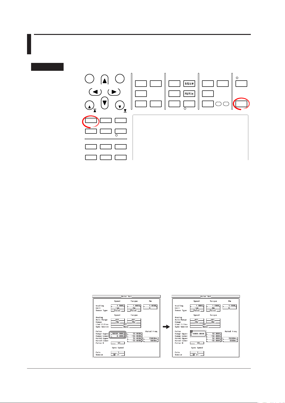
• Setting the Pulse Input Range of the Revolution Signal
If the revolution signal type is Pulse, set the upper and lower limits of the pulse input
range.
Press the cursor keys to select Pulse Range Upper under Speed.
2.
Press SET. A pulse input range setup box appears.
3.
Press the cursor keys to set the upper limit of the pulse input range.
4.
Press SET or ESC to close the box.
5.
Press the cursor keys to select Pulse Range Lower under Speed.
6.
Press SET. A pulse input range setup box appears.
7.
Press the cursor keys to set the lower limit of the pulse input range.
8.
Press SET or ESC to close the box.
9.
1
• Setting the Pulse Input Range of the Torque Signal
If the torque signal type is Pulse, set the upper and lower limits of the pulse input
range.
2.
3.
4.
5.
6.
7.
8.
9.
1.6 Setting the Pulse Range, Pulse Count, and Pulse Rating
Motor Evaluation Function (Motor Version)
Press the cursor keys to select Pulse Range Upper under Torque.
Press SET. A pulse input range setup box appears.
Press the cursor keys to set the upper limit of the pulse input range.
Press SET or ESC to close the box.
Press the cursor keys to select Pulse Range Lower under Torque.
Press SET. A pulse input range entry box appears.
Press the cursor keys to set the lower limit of the pulse input range.
Press SET or ESC to close the box.
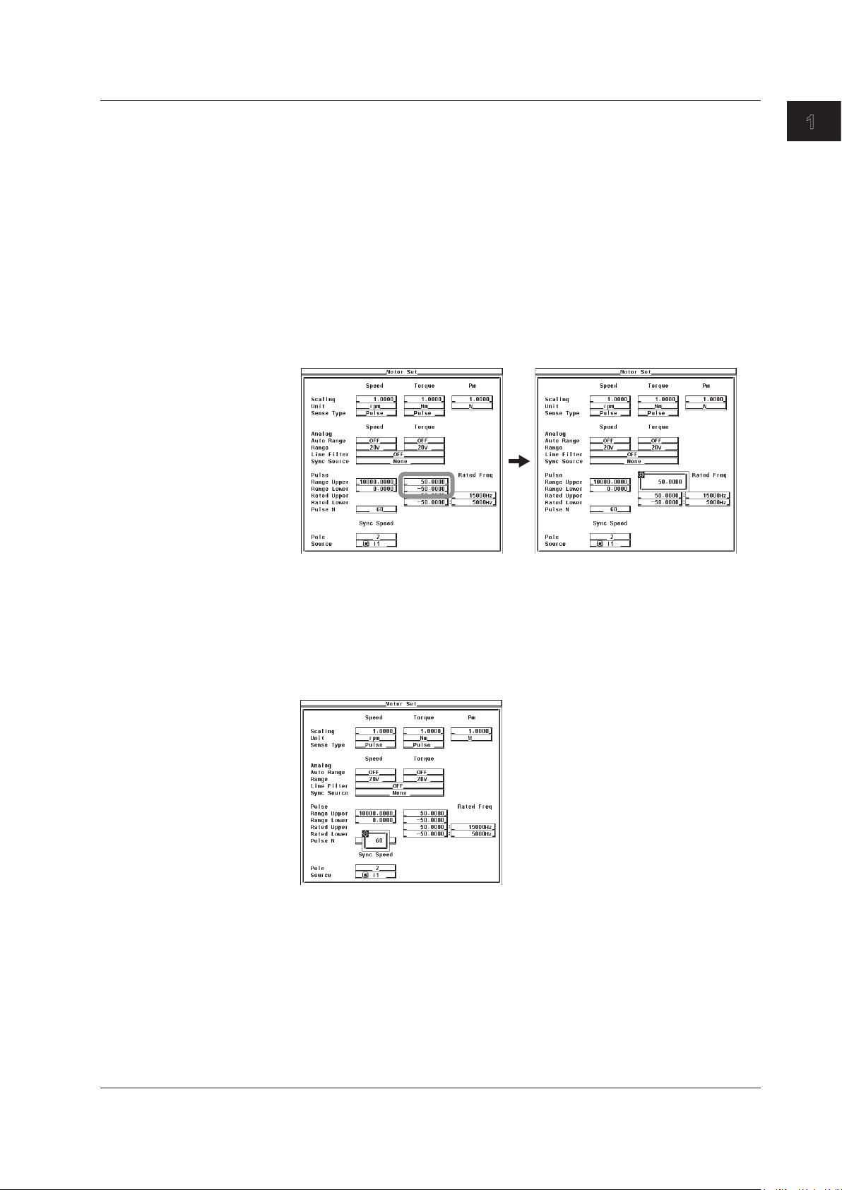
• Setting the Pulse Count per Revolution of the Revolution Signal
2.
3.
4.
5.
Press the cursor keys to select Pulse N.
Press SET. A pulse count entry box appears.
Press the cursor keys to set the pulse count.
Press SET or ESC to close the box.
IM 760301-51E
1-13
1-14
IM 760301-51E
1.6 Setting the Pulse Range, Pulse Count, and Pulse Rating
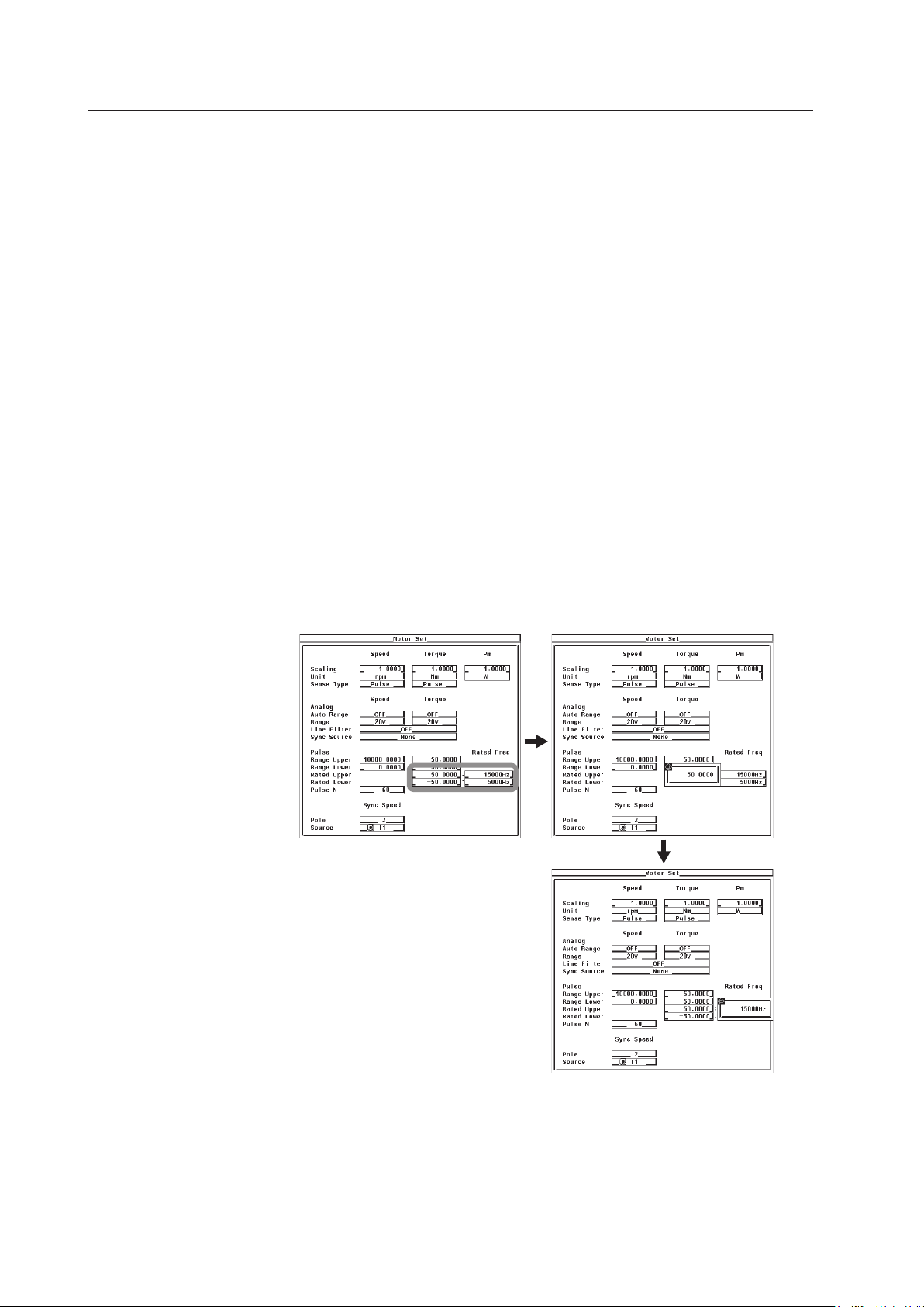
• Setting the Pulse Rating of the Torque Signal
Set the pulse rating of the torque sensor.
• Setting the Positive Rating
Press the cursor keys to select Pulse Rated Upper under Torque.
2.
Press SET. A pulse rating (torque) entry box appears.
3.
Press the cursor keys to set the positive pulse rating (torque).
4.
Press SET or ESC to close the box.
5.
Press the cursor keys to select Rated Upper under Rated Freq under Torque.
6.
Press SET. A pulse rating (pulse frequency) entry box appears.
7.
Press the cursor keys to set the positive pulse rating (pulse frequency).
8.
Press SET or ESC to close the box.
9.
• Setting the Negative Rating
Press the cursor keys to select Pulse Rated Lower under Torque.
2.
Press SET. A pulse rating (torque) entry box appears.
3.
Press the cursor keys to set the negative pulse rating (torque).
4.
Press SET or ESC to close the box.
5.
Press the cursor keys to select Rated Lower under Rated Freq under Torque.
6.
Press SET. A pulse rating (pulse frequency) entry box appears.
7.
Press the cursor keys to set the positive pulse rating (pulse frequency).
8.
Press SET or ESC to close the box.
9.

1
Explanation
1.6 Setting the Pulse Range, Pulse Count, and Pulse Rating
• Pulse Input Range
Set an appropriate range that includes the maximum and minimum values of the input
signal. For example, if you are measuring a signal whose rotating speed is between
120 rpms and 180 rpms and the torque is between –18 N·m to +18 N·m, set the pulse
input range of the rotating speed to 100 rpms to 200 rpms and that of the torque to
–20 N·m to +20 N·m.
The selectable range of pulse range of input signals is as follo
ws:
• Revolution signal: 0.0001 to 99999.9999 [rpm]
Torque signal: –10000.0000 to 10000.0000 [N·m]
•
If the input signal type is Pulse, the upper and lower limits of the waveform display are
set to the values specified here.
• On models with the D/A output (option), the rated value of the
D/A output is as
follows.
Input Signal of Rotating Speed or Torque D/A Output
Pulse Range Upper setting +5 V
PulseRange
Uppersetting×(–1) –5 V
• Setting the Rotation Pulse Count
Set the pulse count per rotation. Set the value in the range of 1 to 9999.
Motor Evaluation Function (Motor Version)
Rotating Speed =
Pulse count (pulse count per revolution)
* If the scaling factor is 1, the rotating speed is the number of rotations per minute (min
or rpm). In addition, if the revolution signal is a changed signal, you can set the scaling
factor (see section 1.7) to determine the rotating speed before the change.
Input pulse count from the revolution sensor per minute
×scalingfactor
*
• Pulse Rating of the Torque Signal
If the torque signal type is Pulse, set the positive and negative ratings of the torque
sensor. Refer to the torque sensor specifications to set the values.
The selectable range of the values is as follows:
•
Torque: –10000.0000 to 10000.0000 [N·m]
Pulse count: 1 to 100000000 [Hz]
•
Torque = (torque pulse coefficient*1×pulsefrequency+torquepulseoffset*1×scalingfactor
*1 The torque pulse count and torque pulse offset are set as shown in the figure on the next
page depending on the pulse rating of the torque signal.
*2 If the torque signal is a changed signal, you can set the scaling factor (see section 1.7) to
determine the torque before the change.
–1
*2
IM 760301-51E
1-15
1-16
IM 760301-51E
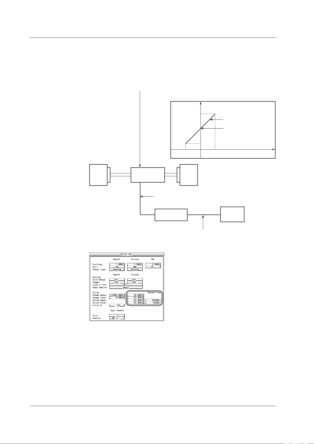
Specifications of the pulse output torque sensor
Pulse rating (positive): Outputs 15 kHz for 50 N·m
Pulse rating (negative): Outputs 5 kHz for –50 N·m
Torque pulse offset
Number of
output pulse
15 kHz
5 kHz
–50 N ·m
Output
axis
50 N· m Input torque
Torque signal to the WT3000
Pulse signal corresponding to –20 N· m to +20 N·m
D/A output signal to the recorder
5 V for –20 N·m to +20 N·m
Pulse input range and pulse rating
settings of the torque signal
Motor Load
WT3000
Recorder
Pulse output
torque sensor
Slope: Torque pulse
coefficient
1.6 Setting the Pulse Range, Pulse Count, and Pulse Rating
• Relationship between the Pulse Input Range and Pulse Rating of the
Torque Signal
If the torque sensor with the specifications below is used to measure the torque in the
range of –20 N·m to +20 N·m, the pulse input range and pulse rating settings are as
shown in the scree example below.
1
1.7 Setting the Scaling Factor and Unit
START STOP
REMOTE
CAL
MOTOR
SET
CURSOR NULL
MENU STORE SET
MENU
LOWER ITEM LOWER FORM ALLUSER SET
DISPLAY
ITEM & ELEMENT
RESET SET
PAGE PAGE
SCALING
HRM SET
MEASURE
SYNC SOURCE
AVG
LINE FILTER
FREQ
FILTER
FILE
PRINT
MISC
STORE
IMAGE SAVE
HELP
NUMERIC
WAVE
OTHERS
ITEM
FORM
U / I / P
WP/q/
TIME
USER
ELEMENT
UPDATE
RATE
HOLD
SINGLE
INTEG
LOCAL
SHIFT
To exit the menu during operation, press ESC located above the
soft keys.
In the procedural explanation below, the phrase “press the cursor
keys” may be used. This phrase refers to the procedures for
selecting items and entering values and character strings. For
details on the procedures, see section 3.14 in the User’s Manual
IM760301-01E.
Cursor keys
Procedure
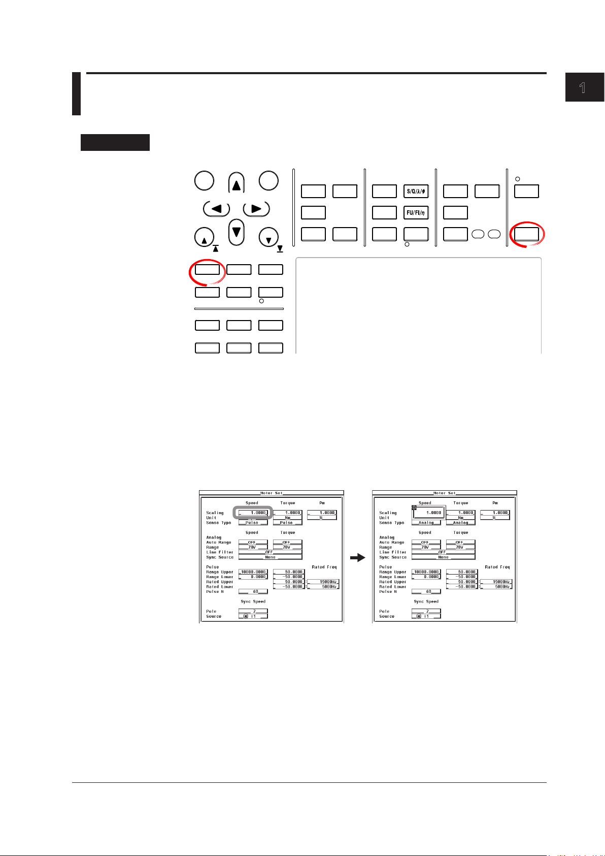
Press SHIFT+SCALING (MOTOR SET) to display the Motor Set dialog box.
1.
Motor Evaluation Function (Motor Version)
• Setting the Scaling Factor Used to Transform the Revolution Signal
Press the cursor keys to select Scaling under Speed.
2.
Press SET. A scaling factor entry box appears.
3.
Press the cursor keys to set the scaling factor.
4.
Press SET or ESC to close the box.
5.
IM 760301-51E
1-17
1-18
IM 760301-51E
1.7 Setting the Scaling Factor and Unit
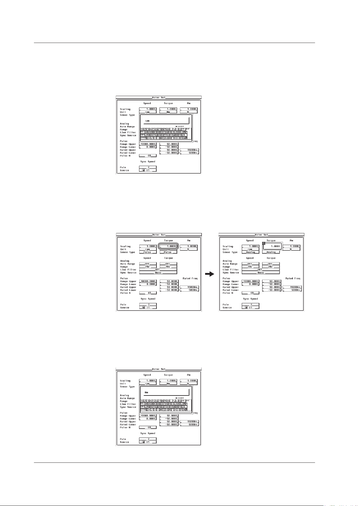
• Setting the Unit of Rotating Speed
Press the cursor keys to select Unit under Speed.
2.
Press SET. A keyboard appears.
3.
Use the keyboard to set the unit.
4.
For keyboard operations, see section 3.14 in the User’s Manual IM760301-01E.
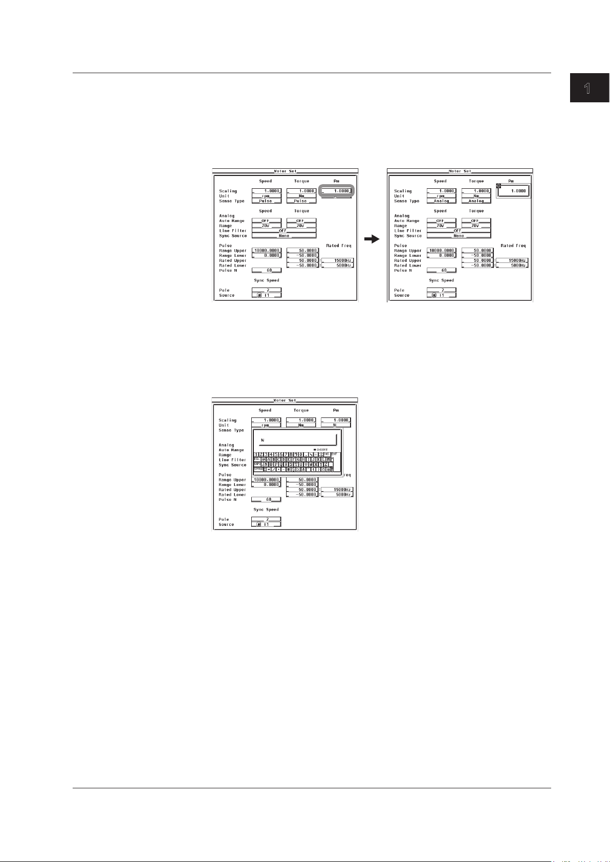
• Setting the Scaling Factor Used to Transform the Torque Signal
Press the cursor keys to select Scaling under Torque.
2.
Press SET. A scaling factor entry box appears.
3.
Press the cursor keys to set the scaling factor.
4.
Press SET or ESC to close the box.
5.
• Setting the Unit of Torque
Press the cursor keys to select Unit under Torque.
2.
Press SET. A keyboard appears.
3.
Use the keyboard to set the unit.
4.
For keyboard operations, see section 3.14 in the User’s Manual IM760301-01E.
1
• Setting the Scaling Factor Used to Compute the Motor Output
• Setting the Unit of Motor Output
1.7 Setting the Scaling Factor and Unit
Press the cursor keys to select Scaling under Pm.
2.
Press SET. A scaling factor entry box appears.
3.
Press the cursor keys to set the scaling factor.
4.
Press SET or ESC to close the box.
5.
Press the cursor keys to select Unit under Pm.
2.
Press SET. A keyboard appears.
3.
Use the keyboard to set the unit.
4.
For keyboard operations, see section 3.14 in the User’s Manual IM760301-01E.
Motor Evaluation Function (Motor Version)
IM 760301-51E
1-19

1-20
IM 760301-51E
1.7 Setting the Scaling Factor and Unit
Explanation
• Setting the Scaling Factor Used to Transform the Revolution Signal
Set the factor used to transform the revolution signal. Set the value in the range of
0.0001 to 99999.9999.
• When the Revolution Signal Type is
Analog
By setting the number of rotations per volt of input voltage, the rotating speed is
derived from the following equation.
Rotating
speed=Inputvoltagefromtherevolutionsensor×scalingfactor
• When the Revolution Signal Type is Pulse
The value is used as a scaling factor in the equation given in “Setting the Rotation
Pulse Count” in section 1.6
• Setting the Scaling Factor Used to Transform the Torque Signal
You can specify the scaling factor used to transform the torque signal to the torque of
the motor. Set the value in the range of 0.0001 to 99999.9999.
• When the Torque Signal T
By setting the torque per volt of input voltage, the torque is derived from the input
voltage from the torque meter using the following equation.
Torque
=Inputvoltagefromthetorquemeter×scalingfactor
• When the Torque Signal Type is Pulse
The value is used as a scaling factor in the equation given in “Setting the Torque
Signal Pulse Count” in section 1.6
ype is Analog
• Setting the Scaling Factor Used to Compute the Motor Output
You can specify the scaling factor used to compute the motor output (mechanical
power) from the rotating speed and torque. Set the value in the range of 0.0001 to
99999.9999.
The equation is indicated below
are set so that the unit of the rotating speed is min
. The scaling factors of the rotating speed and torque
–1
(or rpm) and the unit of torque
is N·m. When the scaling factor of the motor output specified here is 1, the unit of the
motor output Pm is W. Because the efficiency in section 1.9 is computed with the unit
of Pm to be W, it is recommended that the scaling factor of each item be set so that
the unit of Pm is W.
Motor output Pm =
60
*1 Rotating speed derived in section 1.6.
*2 Torque derived in section 1.6.
2×π×rotatingspeed
*1
×scalingfactor×torque
*2
• Setting the Unit of Rotating Speed, Torque, and Motor Output
• Number of Characters
Eight characters or less.
• Types of Characters
Characters that are displayed on the keyboard or spaces.
1
1.8 Setting the Motor and Frequency Measurement
START STOP
REMOTE
CAL
MOTOR
SET
CURSOR NULL
MENU STORE SET
MENU
LOWER ITEM LOWER FORM ALLUSER SET
DISPLAY
ITEM & ELEMENT
RESET SET
PAGE PAGE
SCALING
HRM SET
MEASURE
SYNC SOURCE
AVG
LINE FILTER
FREQ
FILTER
FILE
PRINT
MISC
STORE
IMAGE SAVE
HELP
NUMERIC
WAVE
OTHERS
ITEM
FORM
U / I / P
WP/q/
TIME
USER
ELEMENT
UPDATE
RATE
HOLD
SINGLE
INTEG
LOCAL
SHIFT
To exit the menu during operation, press ESC located above the
soft keys.
In the procedural explanation below, the phrase “press the cursor
keys” may be used. This phrase refers to the procedures for
selecting items and entering values and character strings. For
details on the procedures, see section 3.14 in the User’s Manual
IM760301-01E.
Cursor keys
Source for Computing the Sync Speed and Slip
Procedure
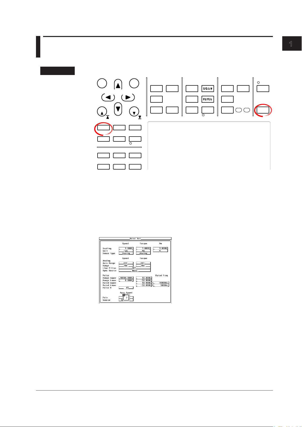
Press SHIFT+SCALING (MOTOR SET) to display the Motor Set dialog box.
1.
Motor Evaluation Function (Motor Version)
• Setting the Motor’s Number of Poles
Press the cursor keys to select Pole.
2.
Press SET. A box for entering the number of poles appears.
3.
Press the cursor keys to set the number of poles.
4.
Press SET or ESC to close the box.
5.
IM 760301-51E
1-21
1-22
IM 760301-51E
120 × frequency of the frequency measurement source (Hz)
Motor’s number of poles
Rotating speed SyncSp (min
–1
) =
1.8 Setting the Motor and Frequency Measurement Source for Computing the Sync Speed and Slip
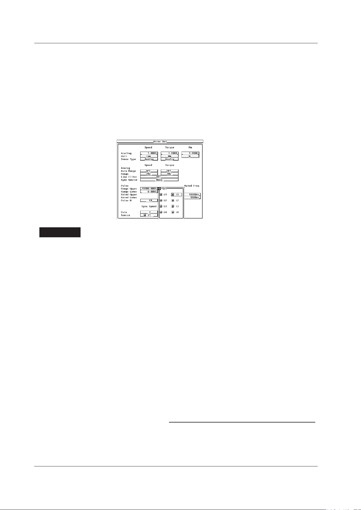
• Selecting the Frequency Measurement Source Signal (Voltage or
Current Signal Supplied to the Motor)
Press the cursor keys to select Sync Speed Source.
2.
Press SET. A frequency measurement source selection box appears.
3.
Press the cursor keys to select any of the target input signals for frequency
4.
measurement (see section 5.3 in the User’s Manual IM760301-01E).
When the button to the left of the input signal in the selection box is highlighted,
that is the source input signal for frequency measurement selected in section 5.3
in the User’s Manual IM760301-01E.
Press SET to confirm the frequency measurement source.
5.
Explanation
• Setting the Motor’s Number of Poles
The number can be set in the range of 1 to 99. Sets the number of poles for the motor
being measured.
• Setting the Frequency Measurement Source Signal
• Select the frequency measurement source from the choices below. The selectable
items vary depending on the installed elements.
U1, I1, U2, I2, U3, I3, U4, and I4
• Se
lect any of the source input signals for frequency measurement. When the button
to the left of the input signal in the frequency measurement source selection box is
highlighted, that is the source input signal for frequency measurement selected in
section 5.3 in the User’s Manual IM760301-01E. If you select an input signal that is
not a frequency measurement source, an error results.
•
In normal cases, the frequency measurement source (see section 5.3 in the
Manual IM760301-01E) is set to the voltage or current supplied to the motor. If
a frequency other than that of the voltage and current supplied by the motor is
specified, the synchronous speed may not be determined correctly.
User’s
• Equation for Deriving the Synchronous Speed
The unit of synchronous speed is fixed to min–1 (or rpm). The equation is indicated
below.

1
× 100
Synchronous speed (min
–1
) – rotating speed*(min–1)
Rotating speed (min
–1
)
Slip (%) =
* Rotating speed derived in section 1.6.
1.8 Setting the Motor and Frequency Measurement Source for Computing the Sync Speed and Slip
• Equation for Deriving the Slip
The unit of synchronous speed is fixed to min–1 (or rpm). Therefore, to determine the
slip, set the scaling coefficient of the rotating speed (see section 1.7) so that the unit
of rotating speed s also min
–1
(or rpm).
Note
Please select a stable voltage or current (supplied by the motor) with small distortion or noise
for the frequency measurement source.
Motor Evaluation Function (Motor Version)
IM 760301-51E
1-23
 Loading...