

Page 1
User’s
Manual
Model VJS7
Potentiometer Converter
(Isolated Single-output and Isolated Dualoutput Types)
Thank you for purchasing the JUXTA Signal Conditioner.
Please read through this manual before use for correct handling.
IM 77J01S07-01E
5th Edition Mar. 2012(YK)
Network Solutions Business Division
2-9-32, Naka-cho Musashino-shi, Tokyo 180-8750 Japan
Phone: +81-422-52-7179 Facsimile: +81-422-52-6619
CAUTIONARY NOTES FOR SAFE USE OF
THE PRODUCT
This User’s Manual should be carefully read before installing
and operating the product. The following symbol is used on the
product and in this manual to ensure safe usage.
This symbol is displayed on the product when it is
necessary to refer to the User's Manual for information
on personal and instrument safety. This symbol is
displayed in the User's Manual to indicate precautions
to avoid danger to the operator, such as an electric
shock.
The following symbols are used only in this manual.
Note
Draws attention to essential information for
understanding the operations and/or functions of the
product.
CHECKING PRODUCT SPECIFICATIONS
AND PACKAGE
(1) Checking the Model and Product Specications
Check that the model and specications indicated on the
nameplate attached to the main unit are as ordered.
(2) Packaged Items
Check that the package contains the following items:
• VJS7: 1
• Tag number label: 1
• Range label: 1
• User's Manual (this manual)
GENERAL
This plug-in type converter is used in combination with
transmitters which send displacement information of regulator
valves by resistance change signals from a potentiometer, and
converts the resistance change into isolated DC current or DC
voltage signals.
Output-2 can be selected from DC voltage signal, DC current
signal, communication function (RS-485), or alarm output (2
relay contacts).
Various parameters such as input range can be set and modied
using a PC (VJ77) or Handy Terminal (JHT200 and the like).
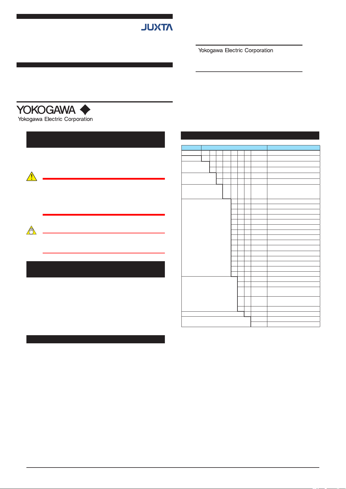
MODEL AND SUFFIX CODES
Model Sufx codes Description
VJS7 -0 □ □ -□ □ □ 0 /□□ Potentiometer Converter
Output
conguration
Power supply 6 100-240 V AC/DC
Input signal -1 Potentiometer resistance
Output-1 A 4 to 20mA DC
Output-2 A 4 to 20mA DC
Options Blank: With socket
*1 Operating range: 85-264 V
*2 Operating range: 12-36 V
*3 DC voltage signal or DC current signal
-0 Always 0
1 Single
2 Dual
7 15-30V DC
(Total resistance: 100Ω to
10kΩ)
B 2 to 10mA DC
C 1 to 5mA DC
D 0 to 20mA DC
E 0 to 16mA DC
F 0 to 10mA DC
G 0 to 1mA DC
1 0 to 10mV DC
2 0 to 100mV DC
3 0 to 1V DC
4 0 to 10V DC
5 0 to 5V DC
6 1 to 5 V DC
7 −10 to +10V DC
Z (Custom Order)
6 1 to 5V DC
P Communication function
(RS-485)
T High/low limit alarm output
(2 relay contacts)
N None
0 Always 0
/SN Without socket
[STYLE: S1]
(*1)
(*2)
(*3)
1
Page 2
1. MOUNTING METHOD
Mounting
Note
Insert/pull out the main unit into/from the socket
vertically to the face of socket. Otherwise the terminals
are bent and it may cause a bad contact.
1.1 Wall Mounting
Loosen the main unit-xing screw of the product and pull out the
main unit from the socket. Fix the socket on the wall with screws.
Next, insert the main unit into the socket and fasten the main unit
with the main unit-xing screw.
screws
Main unit
Mounting Dimensions
Socket
29.5 or more
22±0.2
Unit: mm
2-M4 or
2-ø4.5 or more
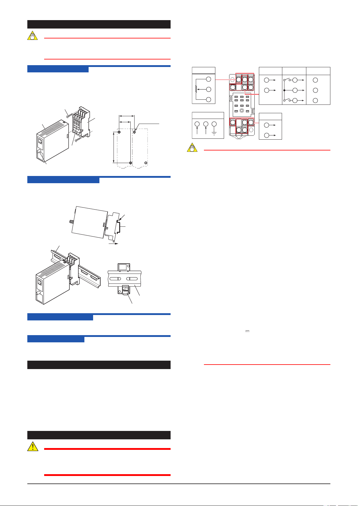
Wiring should be connected to the terminals on the socket
of the product. The terminals for external connections are of
M3 screws. Use crimp-on terminal lugs for connections to the
terminals.
Recommended cables: A nominal cross-sectional area of
0.5 mm2 or thicker for signal cables, and that of 1.25 mm2 or
thicker for power cables.
Input
100%
1
CENTER
3
0%
4
Power Supply
1110 8
N–
L+
GND
3 2
1011
56
1
4
789
Output-2
Analog output
+
2
–
5
Output-1
Analog output
+
7
–
9
Alarm output
ALM1
2
COM
5
ALM2
6
RS-485
Communication
2
5
6
B+
A–
COM
Main unit-fixing
screw
Threaded hole for
fixing the main unit
59±0.3
1.2 DIN Rail Mounting
Insert a DIN rail into the upper part of the DIN rail groove on the
rear of the socket, and then slide the slide lock at the lower part of
the socket upwards until the socket is xed into position as shown
below
Fit into here
DIN rail
DIN rail
Push
(Rear of socket)
DIN rail
Slide look
1.3 Mounting Using
When using a multi-mounting base, see the User's Manual for
VJCE (VJCE Mounting Base).
1.4 Using a Duct
When using a wiring duct, install the duct at least 30 mm away
from the top and bottom faces of the main unit.
2. INSTALLATION LOCATION
● Avoid the following environments for installation locations:
Areas with vibration, corrosive gases, dust, water, oil, solvents,
direct sunlight, radiation, a strong electric eld, and/or a strong
magnetic eld, altitude of more than 2000m above sea level.
● If there is any risk of a surge being induced into the power
line and/or signal lines due to lightning or other factors, a
dedicated lightning arrester should be used as protection for
both this converter and a eld-installed device.
● Operating temperature/humidity range: 0 to 50C/5 to 90%RH
(no condensation)
Note
● Do not use output-2 for the single-output type.
● The power line and input/output signal lines should
be installed away from noise-generating sources.
Other wise accuracy cannot be guaranteed.
● The grounding resistance must be 100 Ω or less
(JIS Class D grounding). The length and thickness
of the grounding cable should be as short and thick
as possible. Directly connect the lead from the
ground terminal (terminal no. 8) of the product to the
ground. Do not carry out daisy-chained inter-ground
terminal wiring
● Use of the product ignoring the specications may
cause overheating or damage. Before turning on the
power, ensure the following:
Power supply voltage and input signal value applied to
the product should meet the required specications.
The external wiring to the terminals and wiring to ground
are as specications.
● Do not operate the product in the presence of
ammable or explosive gases or vapors. To do so is
highly dangerous.
● The product is sensitive to static electricity;
exercise care in operating it. Before you operate
the product, touch a nearby metal part to discharge
static electricity.
● The use of inductance (L) loads such as auxiliary
relays and solenoid valves causes malfunction or
relay failure; always insert a CR lter or diode for
spark-removal into the line in parallel with the load.
Recommended CR
• C: 0.5 to 1F against contact current 1 A
• R: 0.5 to 1 against contact voltage 1 V
● For 15-30 V DC
measure, always install a circuit breaker (an IEC
60947-compatible product, 5 A, 100 V or 220 V AC)
in an easily accessible location near the instrument.
Moreover, provide indication that the switch is a
device for turning off the power to the instrument.
(±20%) power supply, as a safety
3. EXTERNAL WIRING
WARNING
Be sure to turn OFF the power supply before wiring to
avoid the risk of electric shock. Use a tester or similar
device to ensure that no power is being supplied to a
cable to be connected.
2
IM 77J01S07-01E 5th Edition Mar. 02, 2012-00
Page 3

4. DESCRIPTION OF FRONT PANEL
How to connect with the setting tool
4.1 Front Panel
The communications connector in the front panel is used for
setting up parameters through a PC (VJ77 PC-based Parameters
Setting Tool) or the Handy Terminal. The alarm-1 and alarm-2
LEDs light up if an alarm occurs (those LEDs are provided only
when the output-2 is specied for alarm output).
Communications connector
Alarm-1 LED
Alarm-2 LED
4.2 Connector for Communication
Use the connector for communication when setting the
parameters using a PC (VJ77 Parameters Setting Tool) or the
Handy Terminal
JUXTA communication cable
with 5-pin connector (F9182EE)
JHT200
Handy Terminal
PC which is installed
with the VJ77
● Use the VJ77 of version R1.04 or later.
● The modular jack conversion adapter does not come with the
JHT200 Handy Terminal. It is sold separately.
[Provided with VJ77 and JHT200]
Dedicated cable (E9786WK)
[Provided with VJ77]
5. SETTING PARAMETERS
Set the parameters using a PC (VJ77 Parameter Setting Tool) or
the Handy Terminal. Refer to “7. LIST OF PARAMETERS” in this
manual and the User’s Manual for VJ77 PC-based Parameters
Setting Tool (IM 77J01J77-01E) or the User’s Manual for JHT200
Handy Terminal (IM JF81-02E). Parameters are indicated inside
the [ ].
5.1 Settings Related to Inputs and Outputs
5.1.1 Total resistance
Set the total resistance in [D06: RESIST].
Setting range: 100 to 10000 Ω
5.1.2 Input Range
Set the 0% value of input range in [D22: INPUT1 L_RNG],
and the 100% value of input range in [D23: INPUT1 H_RNG].
5.1.3 Burnout
Set the burnout operation in [D30: BURN OUT].
Set “OFF”, “UP”, or “DOWN.”
5.1.4 Direction of Output Action
Analog output signals can be reversed. To reverse the
signal from output-1, set [D38: OUT1 DR] to REVERSE. For
output-2, set [D39 OUT2 DR] to REVERSE. To return the
output-1 signal to normal, set [D38: OUT1 DR] to DIRECT.
For output-2, set [D39: OUT2 DR] to DIRECT.
5.2 Settings Related to Communication
Function
Set the following parameters when output-2 is specied
for communication function. For more information on the
communication function, see the Instruction Manual for VJ Series
Modular jack conversion
adapter (E9786WH)
[Provided with VJ77]
Dedicated adapter (E9789HA)
[Provided with VJ77]
Communication Function (IM 77J1J11-01E).
5.2.1 Communication Protocol
Set the communication protocol by selecting from among
PCLINK, PC-LINK WITH SUM, MODBUS ASCII, MODBUS
RTU, and LADDER in [F01: PROTOCOL].
5.2.2 Communication Address
Set the address number of the isolator numerically in a range
of 1 to 99 in [F02: ADDRESS].
5.2.3 Baud Rate
Set the baud rate by selecting from among 1200, 2400, 4800,
and 9600 bps in [F03: BAUD RATE].
5.2.4 Parity
Select and set NONE, EVEN, or ODD in [F04: PARITY].
5.2.5 Data Length
Select and set 7 bits or 8 bits in [F05: DATA LEN].
5.2.6 Stop Bit
Select and set 1 bit or 2 bits in [F06: STOP BIT].
5.2.7 Input Decimal Point Position
Number of digits of decimal places can be set.
Select and set among 0 to 5 digits in [F07: INPUT DEC PT].
5.3 Settings Related to Alarm Output
Set the following parameters when output-2 is specied for alarm
output.
5.3.1 Alarm Setpoints
Set the alarm setpoints of alarm-1 and alarm-2 in [E03: SET
POINT1] and [E04: SET POINT2] numerically.
• Setting range: A range of 0 to 100% of input range
• Setting resolution: 0.1%
5.3.2 Direction of Alarm Action
Select the direction of alarm-1 action and that of alarm-2
action from among HIGH ALM (high-limit alarm) and LOW
ALM (low-limit alarm) and set each in [E05: ALM1 ACTION]
(direction of alarm-1 action) or [E06: ALM2 ACTION]
(direction of alarm-2 action).
• To activate alarm status when input signal ≥ alarm setpoint,
select HIGH ALM.
• To activate alarm status when input signal ≤ alarm setpoint,
select LOW ALM.
5.3.3 Hysteresis
Set alarm-1 and alarm-2 hysteresis, in [E09: HYSTERESIS1]
and [E10: HYSTERESIS2]. Hysteresis is a value added to the
alarm setpoint in order for an alarm status to be released (to
normal) after the alarm status has been activated. The alarm
status will be released in the following conditions, depending
on the direction of alarm action.
1. * When HIGH ALM (high-limit alarm) is set: Alarm is
released when input signal < (alarm setpoint - hysteresis).
2. * When LOW ALM (low-limit alarm) is set: Alarm is
released when input signal > (alarm setpoint + hysteresis).
• Setting range: A range of 0 to 100% of input range
• Setting resolution: 0.1%
3
IM 77J01S07-01E 5th Edition Mar. 02, 2012-00
Page 4

5.3.4 Alarm ON Delay and Alarm OFF Delay
[1]: Alarm status does not continue for more than 1 second after
Set alarm-1 and alarm-2 ON delays in [E11: ON DELAY1] and
[E12: ON DELAY2] and then alarm-1 and alarm-2 OFF delays
in [E13: OFF DELAY1] and [E14: OFF DELAY2]. An alarm
ON delay is a delay time from the establishment of alarm
condition to alarm output; an alarm OFF delay is a delay time
from the establishment of return-to-normal condition to output.
• Setting range: 0 to 999 seconds
• Setting resolution: 1 second (Note that about 0.2 second will
be added to set time to prevent erroneous operation.)
For example, when an alarm ON delay is set to 1 second,
alarm output is generated if alarm status continues for
more than 1 second after the input value exceeds the
alarm setpoint. Further, when an alarm OFF delay is set
to 2 seconds, alarm output is released if normal condition
continues for more than 2 seconds after the input value has
returned to normal from the alarm status.
5.3.5 Direction of Relay Action
Set the direction of relay energizing in alarm-1 normal
condition and alarm-2 normal condition by selecting from
among NRM DEENERGIZED (de-energized under normal
condition) and NRM ENERGIZED (energized under normal
condition) in [E15: RL1 ACTION] and [E16: RL2 ACTION]
and set them.
6. DESCRIPTION OF ALARM ACTIONS
This chapter describes examples of alarm actions under the
following conditions.
Item Alarm-1 Alarm-2
Direction of alarm
action
Alarm setting E03: SET POINT1 80% E04 : SET POINT2 15%
Hysteresis E09: HYSTERESIS1 10% E10 : HYSTERESIS2 5%
Alarm ON delay E11: ON DELAY1 1 sec. E12 : ON DELAY2 3 sec.
Alarm OFF delay E13: OFF DELAY1 2 sec. E14 : OFF DELAY2 4 sec.
Description of alarm
actions
Alarm conditions
established
[%]
100
[1]
80
60
1 sec.
Alarm-1
ON delay
40
Alarm-2 hysteresis (5%)
20
15
0
Alarm-1 action
Normal
Alarm-2 action
Parameter Setpoint Parameter Setpoint
E05: ALM1 ACTION High-limit
The alarm sounds if the
condition where the input value
is 80% or more of high-limit
alarm continues for more than 1
second. After the alarm sounds,
when the condition where
input value is less than 70%of
the high-limit alarm continues
for more than 2 seconds, the
status returns to normal
the alarm conditions are established at alarm-1.
[2]: Normal status does not continue for more than 2 seconds after
the normal conditions are established at alarm-1.
[3]: Alarm status does not continue for more than 3 seconds after
the alarm conditions are established at alarm-2.
[4]: Normal status does not continue for more than 4 seconds after
High-limit alarm ON
Normal conditions established
[2]
2 sec.
Alarm-1
OFF delay
Alarm-2 setpoint (15%)
Alarm
Normal Normal
the normal conditions are established at alarm-2.
High-limit alarm OFF
Alarm-1 setpoint (80%)
Alarm-1 hysteresis (10%)
Alarm conditions
established
[3]
E06: ALM2 ACTION Low-limit
alarm
The alarm sounds if the
condition where the input value
is 15% or less of low-limit
alarm continues for more than
3 seconds. After the alarm
sounds, when the condition
where input value is more than
20% of the low-limit alarm
continues for more than 4
seconds, the status returns to
normal.
Low-limit alarm ON
Normal conditions
3 sec.
established
[4]
Normal
Alarm
Alarm-2
ON delay
alarm
Low-limit alarm OFF
Alarm-2
OFF delay
4 sec.
Elapsed time
1 sec.
7. LIST OF PARAMETERS
Parameter Display Item
MODEL Model
TAG NO Tag no.
SELF CHK Self-check result
A DISPLAY1 Display1
A01 INPUT1 Input value 1
A05 OUTPUT1 Output value 1
A06 OUTPUT2 Output value 2
A07 ALM1 STATUS Alarm-1 status
A08 ALM2 STATUS Alarm-2 status
A54 STATUS Status
A56 REV NO Rev. no.
A58 MENU REV MENU REV
A60 SELF CHK Self-check result
B DISPLAY2 Display2
B01 INPUT1 Input value 1
B05 OUTPUT1 Output value 1
B06 OUTPUT2 Output value 2
B07 ALM1 STATUS Alarm-1 status
B08 ALM2 STATUS Alarm-2 status
B60 SELF CHK Self-check result
D SET (I/O) Setting (I/O)
D01 TAG NO.1 Tag no. 1
D02 TAG NO.2 Tag no. 2
D03 COMMENT1 Comment 1
D04 COMMENT2 Comment 2
D06 RESIST Total resistance
D22 INPUT1 L_RNG Input low range
D23 INPUT1 H_RNG Input high range
D38 OUT1 DR Direction of output-1 action
D39 OUT2 DR Direction of output-1 action
D60 SELF CHK Self-check result
E SET(ALM) Setting (alarm output)
E03 SET POINT1 Alarm-1 setting
E04 SET POINT2 Alarm-2 setting
E05 ALM1 ACTION Direction of alarm-1 action
E06 ALM2 ACTION Direction of alarm-2 action
E09 HYSTERESIS1 Alarm-1 hysteresis
E10 HYSTERESIS2 Alarm-2 hysteresis
E11 ON DELAY1 Alarm-1 ON delay setting
E12 ON DELAY2 Alarm-2 ON delay setting
E13 OFF DELAY1 Alarm-1 OFF delay setting
E14 OFF DELAY2 Alarm-2 OFF delay setting
E15 RL1 ACTION Direction of alarm-1 relay action
E16 RL2 ACTION Direction of alarm-1 relay action
E60 SELF CHK Self-check result
F SET(COM) Setting (communication)
F01 PROTOCOL Communication protocol
F02 ADDRESS Address
F03 BAUD RATE Baud rate
F04 PARITY Parity
F05 DATA LEN Data Length
F06 STOP BIT Stop bit
F07 INPUT DEC PT Decimal point position of input
F60 SELF CHK Self-check result
P ADJUST Adjustment
P10 ZERO ADJ1 Zero adjustment of input
P11 SPAN ADJ1 Span adjustment of input
P12 OUT1 0% 0% adjustment of output-1
P13 OUT1 100% 100% adjustment of output-1
P14 OUT2 0% 0% adjustment of output-2
P15 OUT2 100% 100% adjustment of output-2
P60 SELF CHK Self-check result
Q TEST Test
Q02 OUT1 TEST Forced output-1
Q03 OUT2 TEST Forced output-2
Q04 ALM1 TEST Forced output (alarm)
Q05 ALM2 TEST Forced output (alarm)
Q60 SELF CHK Self-check result
*1 The Status is displayed for service personnel to see history
records.
*2 There are items not displayed depending on what output-2
is specied.
*1
*2
*2
*2
4
IM 77J01S07-01E 5th Edition Mar. 02, 2012-00
Page 5

8. MAINTENANCE
The product starts running immediately when the power is turned
on; however, it needs 10 to 15 minutes of warm-up before it
meets the specied performance.
8.1 Calibration Apparatus
● 6-dial decade resistance boxes × 2 units
(Yokogawa Meters & Instruments 279301 or equivalent)
● A digital multimeter (DMM) (Yokogawa 7561 or equivalent)
● A calibrator (Yokogawa Meters & Instruments CA150 or
equivalent)
● A precision resistor of 250 Ω ±0.01%, 1W
● Setting tool for adjustment (Refer to “4.2 Connector for
Communication” in this manual.)
8.2 Calibration Procedure
1. Connect the instruments as shown below. First adjust the
output-1 signal and then the output-2 signal.
100%
0%
2. Operate the variable resistor according to the specications
3. Check to see the corresponding output voltages are 0, 25, 50,
For alarm output, check the relay action by the alarm indicator
lamp or resistance of output terminals.
● Use the setting tool (VJ77 Parameter Setting Tool or JHT200
User’s Manual for VJ77 [Document No.: IM 77J01J77-01E];
however, use the VJ77 of version R1.04 or later.
User’s Manual for JHT200 [Document No.: IM JF81-02E]
R1
R2
Input
R1
6 dial
variable
resistor
6 dial
variable
resistor
R2
Power supply
L+
1110 8
N–
GND
1
3
4
3 2
1
56
4
789
1011
R: For current output using 250 Ω
Output-2
2
+
R
DMM
–
5
Alarm-1
ALM1
2
5
COM
Alarm-2
ALM2
6
5
COM
Output-1
7
+
R
DMM
–
9
precision resistor
+
Calibrator
–
+
Calibrator
–
(total resistance, 0%, 100% resistance) of the potentiometer
to be connected. Keeping total resistance constant, change
each value of R1 and R2 to apply the resistance equivalent to
0, 25, 50, 75, and 100% of the input range to the converter.
75, and 100% respectively and within the specied accuracy
rating. (“R” is used for current output.)
Handy Terminal) to adjust the input/output signals.
SAFETY AND EMC STANDARDS
CAUTION
This instrument is for Measurement Category I (CAT.I).
Do not use it for measurements in locations falling
under Measurement Categories II, III, and IV.
Internal Wiring
Entrance
Cable
IV
III
Outlet
I
Measurement
Description Remarks
category
I CAT.I For measurements performed
on circuits not directly connected
to MAINS.
II CAT.II For measurements performed
on circuits directly connected to
the low-voltage installation.
III CAT.III For measurements performed in
the building installation.
IV CAT.IV For measurements performed
at the source of the low-voltage
installation.
An analog input signal is measurement category I (CAT.I).
Rated transient overvoltage: 1500 V
Note This is a reference safety standard value for
Measurement Category I of IEC/EN/CSA/UL61010-1.
This value is not necessarily a guarantee of instrument
performance.
EMC standards: Complies with EN61326.
The above conformed instrument is only for voltage of 15 to 30
V DC.
* The instrument continues to operate at a measurement
accuracy of within ±20% of the range during testing.
II
T
Appliances,
portable
equipments,
etc.
Distribution
board, circuit
breaker, etc.
Overhead
wire, cable
systems, etc.
(Note)
5
IM 77J01S07-01E 5th Edition Mar. 02, 2012-00
Page 6

Blank Page
 Loading...