

Page 1
General
Specications
Model TDLS8000
Tunable Diode Laser Spectrometer
GS 11Y01D01-01EN
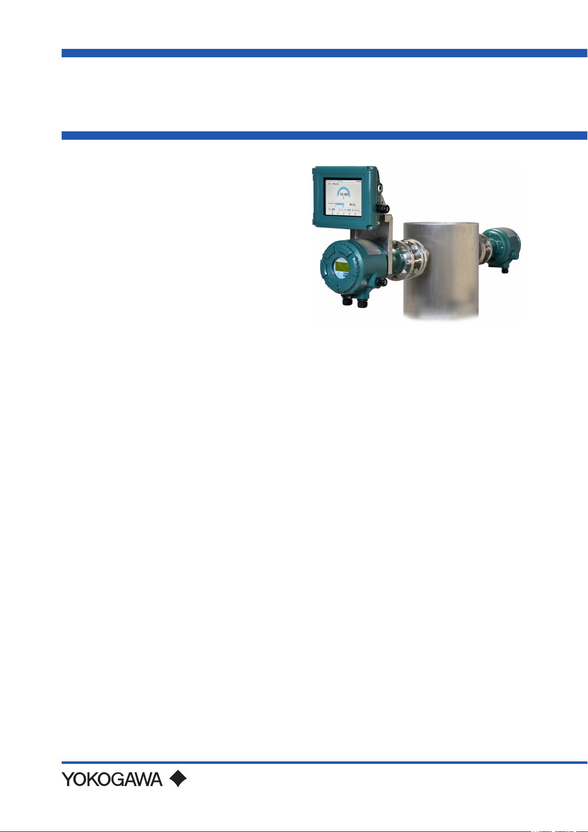
n Overview
Yokogawa’s new TDLSTM8000 houses all of the
industry’s leading features in one robust device.
The platform design is for in situ measurements
which negate the need for sample extraction and
conditioning.
The non-contacting sensor allows for a variety of
process types including corrosive, abrasive and
condensing.
The rst generation platform has been proven in many
others for the measurements of O2, CO, CH4, NH3,
H2O and many more NIR absorbing gases.
This second generation platform has improved
reliability and ease of installation and maintenance
while still meeting or exceeding designed application
demands.
TDLS8000 with YH8000 HMI Unit
n Features
• SIL2, TruePeakTM combined with smart laser
technology
- Measurement integrates the area of the absorbance
and gets a true, interference-free analysis under
changing pressure, temperature and background
- Laser module is replaceable on site without any
calibration or adjustment
- Internal reference cell in the laser module ensures
peak locking during trace measurement
- Laser and Detector modules are sealed to protect
them from dirty purge gas
- On board diagnostics and low TCO(*1) (no moving
parts, high MTTF(*2) for components)
- IEC61508 SIL designed & approved, SIL 2 capability
for single analyzer use, SIL 3 capability for dual
analyzer use
• Intuitive touchscreen HMI
- Large HMI provides easy operation and control of
up to 4 analyzers at the same time·A standard mini
display at both sides enables easy optical alignment
• HART and Modbus TCP communications
standard
•8-stageauto-gainadaptstodicultapplications
- Auto-gain enables wide signal ranges against
dynamic variation of transmission.
•Fullyeldrepairablewith50daysofdataand
spectra storage
•Compactdesignforone-maninstallationwithout
sacricingruggedness
- IECEx, ATEX, FM(US, Canada), Korea Ex, NEPSI,
EAC, Japan hazardous area approvals based on
Nonincendive/Type n or Explosionproof/ame proof.
- Purge gas is no need for explosion protection.
• In-situorextractiveanalysisandfastresponse
(2-5seconds,1second(optional))
• Process pressures up to 1 MPa abs. and process
temperaturesupto1,500ºC(Note)
Note: Maximum process temperatures and pressures
will vary by application
*1: Total Cost of Ownership
*2: Mean Time To Failure
• 10 language display options
YH8000 oers easy touch screen operation and
simple menu structure in 10 languages. Menus of
display, execution and setting are displayed in a
selected language.
Typical gases measured include:
• Oxygen in process and combustion applications.
Process temperatures can be as high as 1,500ºC,
and process pressures can be as high as 1 MPa abs.
Measurement span is typically between 1% and 25%
oxygen.
• Carbon monoxide in process and combustion
applications. Process temperatures can be as high as
1,500ºC. Two versions are available, high sensitivity
with ppm detection limits, and standard sensitivity for
higher ppm and percent level CO measurement
Other applications and gas measurements are possible
with the TDLS8000. Please ll out the Application
Data Sheet at the end of this document and send to
Yokogawa.
TDLS, TruePeak are trademarks or registered trademarks of Yokogawa Electric Corporation.
All other company and product names mentioned in this document are trademarks or registered trademarks of their respective companies.
Please select appropriate equipment in accordance with the laws and regulations of the relevant country/region, when it is used in a location where explosive atmospheres may be present.
Yokogawa Electric Corporation
2-9-32, Nakacho, Musashino-shi, Tokyo, 180-8750 Japan
GS 11Y01D01-01EN
©Copyright Apr. 2015
13th Edition Aug. 28, 2020
Page 2
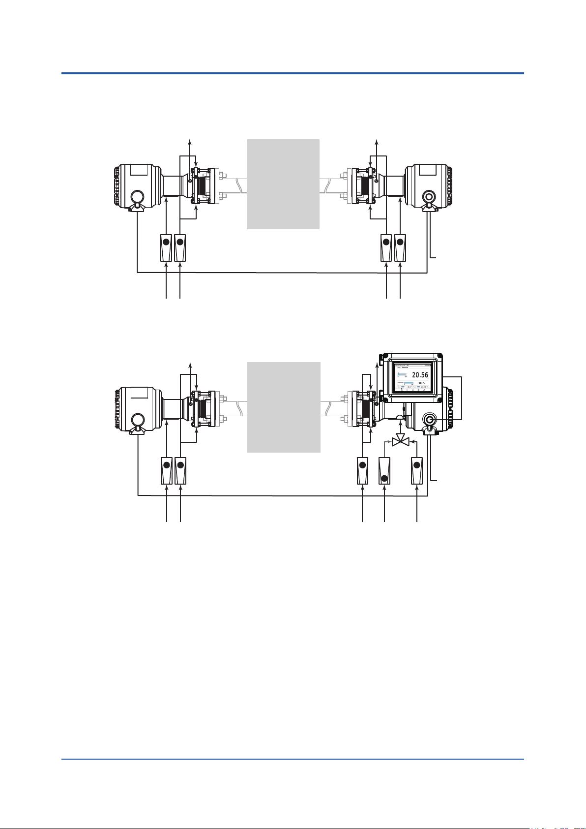
nSystemconguration
StandardSystemConguration
2
Laser unit (LU)
Measured gas
Flow meter Flow meter
Unit connection cable
Purge line for Optic Purge line for Optic
Purge line for Process window Purge line for Process window
Sensor control unit (SCU)
SystemCongurationwithYH8000HMIUnitandValidationgasline
Laser unit (LU)
Measured gas
Sensor control unit (SCU)
24V DC±10%
Flow meter Flow meter
Unit connection cable
Purge line for Optic Purge line for Optic
Purge line for Process window
Purge line for Process window
Check gas line
24V DC±10%
All Rights Reserved. Copyright © 2015, Yokogawa Electric Corporation GS 11Y01D01-01EN Aug 28, 2020-00
Page 3
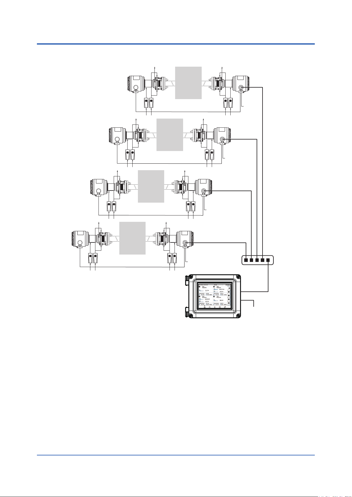
MultiAnalyzerCongurationwithRemoteHMI
Laser unit (LU) Sensor control unit (SCU)
Measured
Measured
gas
3
Measured
gas
24V DC
±10%
gas
24V DC±10%
24V DC±10%
Measured
gas
Flow meter Flow meter
Unit connection cable
Note: If power supply is 100 to 240 V AC, purchase the Universal Power Supply, separately.
If four multi analyzer conguration with remote HMI is made, ve universal power supply including YH8000 are needed.
24V DC±10%
Switching HUB
24V DC±10%
YH8000 HMI Unit
All Rights Reserved. Copyright © 2015, Yokogawa Electric Corporation GS 11Y01D01-01EN
Aug 28, 2020-00
Page 4
4
n STANDARD SPECIFICATIONS
TDLS8000 Tunable Diode Laser Spectrometer
Measurement object:
O2, CO, CO or CH4, CO2, CO + CO2,
H2O, NH3, H2S, HCl concentration in
combustion exhaust gas and process gas
If other gas measurements are required,
consult with Yokogawa
Measurement system:
Tunable diode laser spectroscopy
Light source; Near-infrared tunable diode laser
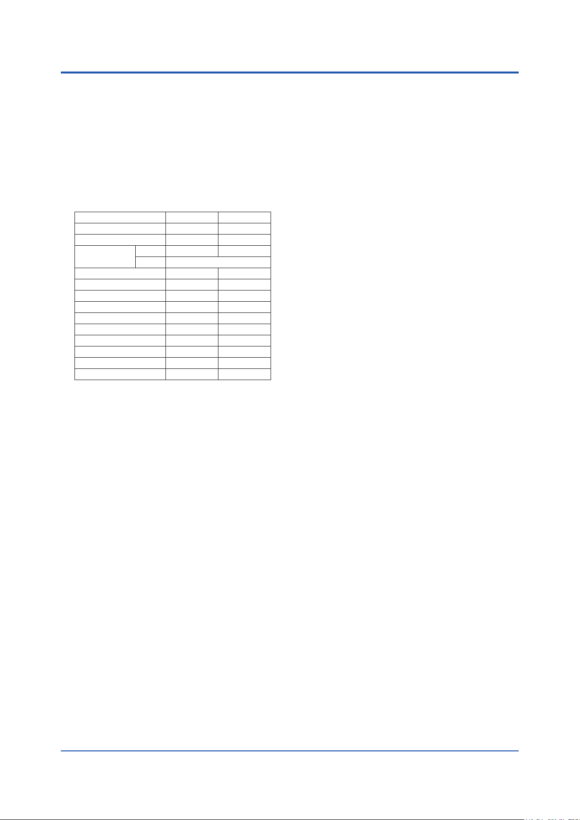
Measured components and ranges:
Measured component Min. range Max. range
O
2
CO (ppm) 0-200 ppm 0-10,000 ppm
CO or CH4 (*3)
NH
3
H2O (ppm) in non HC (*1) 0-30 ppm 0-30,000 ppm
H2O (ppm) in HC (*2) 0-30 ppm 0-30,000 ppm
CO (%) 0-20% 0-50%
CO (%) + CO2 (%) 0-30% 0-100%
H2S 0-5% 0-100%
CO2 (%) High Range 0-1% 0-5%
CO2 (%) Extend. Range 0-30% 0-50%
H2O (%) 0-10% 0-100%
HCl 0-50 ppm 0-5,000 ppm
*1: Non hydrocarbon background.
*2: Hydrocarbon background.
*3: Please consult with Yokogawa if CO or CH4
ingredient coexists.
CO 0-200 ppm 0-10,000 ppm
CH
4
Please consult with Yokogawa if the measuring range
for your sample gas is outside of the above ranges
Optical path length:
Optical distance between the laser unit
and the sensor control unit
Standard; 0.5 to 6 m (Application dependent)
Max; 30 m ( With optional Large Aperture
Optics (LAO))
Note: LAO unit can be selected only with analyzers for
If your optical path length is under 0.5 m or over
25 m (Zone 1/Div.1/Flameproof “d” with LAO)
O2, CO(ppm) and CO+CH
30 m, please consult with Yokogawa.
Safety, EMC, and RoHS conformity standards:
Safety conformity standards:
CE EN61010-1, EN61010-2-030
UL UL61010-1, UL 61010-2-030
CSA CAN/CSA-C22.2 No.61010-1, CAN/
CSA-C22.2 No.61010-2-030
GB GB30439 Part 1
Installation altitude: 2000 m or less
Installation category:
I (Anticipated transient overvoltage 330V)
Measuring category: O (Other)
Pollution degree: 2, Indoor/Outdoor use
Note: Installation category, called overvoltage category,
species impulse withstand voltage. Pollution
degree indicates the degree of existence of solid,
liquid, gas or other inclusions which may reduce
dielectric strength.
0-1% 0-25%
0-5%
0-30 ppm 0-5,000 ppm
4.
EMC conformity standards:
CE EN55011 Class A Group 1
EN61326-1 Class A Table 2 (For use in
industrial location), EN61326-2-3
RCM EN55011 Class A Group 1
KC KN11 Class A Group 1, KN61000-6-2
(Korea Electromagnetic Conformity)
RoHS conformity standards: EN50581
Information of the WEEE Directive
This product is purposely designed to be used in a
large scale xed installations only and, therefore,
is out of scope of the WEEE Directive. The WEEE
Directive does not apply.
The WEEE Directive is only valid in the EU.
Laser classication: CAN/CSA-E60825-1-15,
CE EN 60825-1:2014, FDA 21CFR part
1040.10, GB7247.1-2012, Class 1 laser
product
SIL Certication: The TDLS8000 expect digital output
(2 points), digital input (2 points), valve
control output (2 points), and digital
communications (HART, Modbus/TCP) are
certied in compliance with the following
standard.
IEC 61508:Functional safety of Electrical/
electronic/programmable electronic
related systems; SIL 2 capability for single
analyzer use, SIL 3 capability for dual
analyzer use.
Display:
128 x 64 dots LCD; On Sensor Control Unit
Status LEDs; 3 on Sensor Control Unit (Green:
Power, Orange: DO, Red: Fault)
4 digit 7-segment LEDs: On Laser Unit
Display items:
LCD on Sensor Control Unit; Gas concentration,
Transmission, Process gas temperature
(AI), Process gas pressure (AI), System
status, Alarm information, System
information (Product serial no., Laser
module serial no., Output signal, IP
address, HART address, Optical path
length, Analyzer internal temperature)
7-segment LEDs on Laser Unit; Transmission
Analog output: 2 points, 4 to 20 mA DC (Isolated from
the power supply and ground, Max. load
resistance 550 Ω)
Output types; Gas concentration, Transmission,
Process gas temperature, Process
gas pressure
Output range; 3.0 to 21.6 mA DC
Digital communications:
HART; On analog output signal 1 (AO-1)
Load resistance; 250 to 550 Ω (Include cable resistance)
Ethernet; RJ-45 connector in Sensor Control Unit
Protocol; Modbus/TCP
Communication speed; 100 Mbps
Digital output: 2 points, contact rating 24V DC, 1A
DO;
Function: Activate during Warning / Calibration
/ Validation / Warm up / Maintenance
conditions
Contact Specication: Relay contact output
(Isolated from the power supply and
ground), C-contact (NC/NO/COM)
All Rights Reserved. Copyright © 2015, Yokogawa Electric Corporation GS 11Y01D01-01EN
Aug 28, 2020-00
Page 5

5
Fault;
Function: Activate during Fault condition or when
the system power is o
Contact Specication: Relay contact output
(Isolated from the power supply and
ground), A-contact (NC/COM)
Valve control output: 2 points
Function; Activate calibration or validation solenoid
valves for zero, span or validation gas.
Output signal; 24V DC, 500 mA Max. per terminal
Alarm:
Warning;
Gas concentration low, Gas concentration
high, Transmission low, Process pressure
low, Process pressure high, Process
temperature low, Process temperature
high, Validation required, Validation
failure, Zero calibration error, Span
calibration error, Non process alarm,
External alarm
, Detector signal high,
Absorption too high
Fault;
Laser module temperature low, Laser
module temperature high, Laser
temperature low, Laser temperature high,
Peak center out of range, Reference peak
height low, Transmission lost, Reference
transmission low, Reference peak height
high, Laser unit failure, Laser module error,
File access error, E2PROM access error
Digital input: 2 points
Function; External Alarm/Calibration start/
Validation start/Stream switch (Valve
control)
Contact specication; Zero voltage contact input
(Isolated from the power supply and
ground)
Input signal; Open signal: 100 kΩ or more, Close
signal: 200 Ω or less
Analog input: 2 points
Signal type; 4 to 20 mA DC (Isolated from
the power supply and Ground), with
selectable powered/unpowered function
Input signal range; 2.4 to 21.6 mA DC
Input types; Process gas temperature, Process
gas pressure
Transmitter power supply;
15 V DC or higher (at 20 mA DC)
26 V DC or less (at 0 mA DC)
Note: This voltage is generated between the AI terminals
of TDLS8000. When calculating the minimum
operating voltage for transmitters, consider to allow
margins for voltage drop in external wiring.
Self-diagnostics:
Laser Unit temperature, Sensor Control
Unit temperature, Laser temperature,
Detector signal level, Memory read/write
function, Peak locking condition
Calibration:
Calibration method; Zero/Span calibration
Calibration mode; Manual, Auto (Time initiate,
Remote initiate (DI/Modbus)), Semi-Auto
(YH8000/HART)
Validation:
Validation method; Up to 2 points
Validation mode; Manual, Auto (Time initiated,
Remote initiate (DI/Modbus)), Semi-Auto
(YH8000/HART)
Note: Validation check is not available when Large
Aperture Optics “-LA” of the Optic Accessory
is specied or H20 ppm measurement “-H1” of
the Gas Parameter is specied. As well, when
gas concentration is unstable, please consult
Yokogawa.
Power supply: 24V DC +/-10%
If your power supply is 100 to 240 V AC,
Universal Power Supply, M1276WW (sold
separately), is required
Power consumption:
Max. 20W; TDLS8000 only
Max. 60W;
TDLS8000 with YH8000 and 2 solenoid valves
Protection degree: IP66, Type 4X
Material: Case; Aluminum alloy
Wetted materials:
316 SS, BK-7 glass, Teon encapsulated
FKM (O-ring for alignment ange), Silicone
(O-ring for LAO)
Paint color: Mint green (RAL 190 30 15 or equivalent)
Weight:
Sensor Control Unit; Approx. 8 kg
Laser Unit; Approx. 8 kg
Large Aperture Optics; Approx. 14 kg
ANSI Class 150-2-RF (Eq.) Alignment Flange;
Approx. 5 kg/pc
ANSI Class 150-3-RF (Eq.) Alignment Flange;
Approx. 7 kg/pc
ANSI Class 150-4-RF (Eq.) Alignment Flange;
Approx. 9 kg/pc
DIN PN16-DN50-A (Eq.) Alignment Flange;
Approx. 5 kg/pc
DIN PN16-DN80-A (Eq.) Alignment Flange;
Approx. 6 kg/pc
JIS 10K-50-FF (Eq.) Alignment Flange;
Approx. 5 kg/pc
JIS 10K-80-FF (Eq.) Alignment Flange;
Approx. 6 kg/pc
Flow Cell Alignment Flange; Approx. 5 kg/pc
Cable gland for Japan Ex “-J1”; (/JA1) Approx. 320 g/pc,
(/JB3, /JB4) Approx. 450 g/pc
Cable gland for Japan Ex “-J2”;
(/JC1, /JD1) Approx. 150 g/pc,
(/JE3, /JE4) Approx. 200 g/pc
Process gas condition:
Process gas temperature; Max. 1,500ºC,
Application dependent
Process gas pressure;
abs.,
Max.1 MPa abs., Min. 90 kPa
Application dependent
Max. 15 kPa G with LAO unit
Note:
When using TDLS8000 as CE marking compliance
product, it has following limitation.
General purpose model (-G1, -G2):
The upper limit of the measurement gas
ATEX model (-S1, -S2):
The upper limit of the measurement gas
An unstable gas in this context is a gas liable to
transform itself spontaneously, producing a sudden
pressure increase.
Such transformation as an example can result
from a relatively small variation of an operating
parameter (e.g. pressure, temperature, presence
of catalyzing material) in a conned volume.
This includes gases that are classied as
chemically unstable gases according to CLP
Regulation (EC) No 1272/2008 as amended.
pressure is 50kPa in gauge pressure.
Consult with Yokogawa Europe B.V. in the
case of witnessing high pressure in Europe.
pressure is 500kPa abs. The unstable gas
dened by following cannot be measured.
All Rights Reserved. Copyright © 2015, Yokogawa Electric Corporation GS 11Y01D01-01EN
Aug 28, 2020-00
Page 6

6
Typical examples of unstable gases: acetylene
(UN 1001), methyl acetylene (UN 1060),
vinyluoride (UN 1860), ozone and dinitrogen
oxide (UN 1067).
For further examples, see Table 35.1 of the UN
Manual of Tests and Criteria.
Dust in process gas; 20 g/m3 or less
(Dust loading levels are dependent
upon the application, OPL and other
installation factors)
Warm-up time: 5 min.
Installation condition:
Ambient operating temperature; -20 to 55ºC
Storage temperature; -30 to 70ºC
Humidity; 0 to 95%RH at 40ºC (Non-condensing)
Mounting ange type; ASME B16.5, DIN, JIS
Cable entries;
Sensor Control Unit:
1/2NPT or M20x1.5mm,one hole
3/4NPT or M25x1.5mm, three holes
Laser Unit: 3/4 NPT or M25x1.5mm, one hole
Purge gas connections;
1/4NPT or Rc1/4
If other gas connections are required,
please consult with Yokogawa.
Purge gas;
Theoretically, instrument air could be used as
a purge gas for all of the below applications
except for oxygen or H2O measurement.
Choosing between using nitrogen or
instrument air or purge gas will ultimately
depend upon further application details and
the desired precision of the measurement. All
gasses should be clean and dry.
Recommended purge gasses:
O2 analyzer: N2 (99.99% or greater, application
dependent)
H2O ppm analyzer: N2 (99.99% or greater with
< 20 ppm H2O for feed to the optional
dryer package)
CO, CO or CH4, CO2, CO + CO2, NH3, H2S, HCl
analyzer: N2 (99.99% or greater,
application dependent) or Instrument air
Purge gas ow rates;
Optic:
Application dependent (typ. 2 to 20L/min)
2 to 20L/min and 50 to 70mL/min
(Zone 1/Div.1/Flameproof “d”)
* Not more than 10kPa at the inlet for
Zone 1/Div.1/Flameproof “d” and Zone
2/Div.2/Type of protection “n”
Process window: Application dependent
(typ. 5 to 30L/min)
Hazardousareaclassications:
Division 1, Zone 1: Explosionproof
TDLS8000-D1 (FM Approval for US)
Division system:
Type of protection:
Explosionproof for Class I, Division 1,
Groups A, B, C, D, T5
Dust-Ignitionproof for Class II/III,
Division 1, Groups E, F, G, T5
Enclosure rating: Type4X
Applicable standards:
FM Class 3600: 2018
FM Class 3615: 2018
FM Class 3616: 2011
FM Class 3810: 2018
ANSI/NEMA250: 2013
Zone system:
Type of protection:
Class I, Zone 1, AEx db [op is T6 Ga]
IIC T5 Gb
Zone 21, AEx tb [op is T85˚C Da] IIIC
T100˚C Db
Enclosure rating: IP66
Applicable standards:
ANSI/UL 60079-0:2019
ANSI/UL 60079-1:2015
ANSI/UL 60079-28:2017
ANSI/UL 60079-31:2015
ANSI/IEC 60529:2004
TDLS8000-C1 (FM Approval for Canada)
Type of protection:
Ex db [op is T6 Ga] IIC T5 Gb
Class II/III, Division 1, Groups E, F, G, T5
Ex tb [op is T85˚C Da] IIIC T100˚C Db
Enclosure rating: IP66, Type4X
Applicable standards:
CAN/CSA-C22.2 No.0:2010 (R2015)
CSA-C22.2 No. 0.4:2017
CSA C22.2 No. 0.5:2016
CSA C22.2 No. 25:2017
CSA C22.2 No.94.2:2015
CAN/CSA-C22.2 No.61010-1:2012
CAN/CSA-C22.2 No.61010-2-030:2012
CAN/CSA-C22.2 No.60529:2016
CSA C22.2 No.60079-0:2019
CAN/CSA-C22.2 No.60079-1:2016
CAN/CSA-C22.2 No.60079-28:2016
CAN/CSA-C22.2 No.60079-31:2015
ANSI/ISA 12.27.01:2011
TDLS8000-S1 (ATEX)
Type of protection:
II 2(1) G Ex db [op is T6 Ga] IIC T5 Gb
II 2(1) D Ex tb [op is T85˚C Da] IIIC
T100˚C Db
Enclosure rating:
IP66 (In Accordance with EN 60529)
Applicable standards:
EN IEC 60079-0:2018
EN 60079-1:2014, EN 60079-28:2015,
EN 60079-31:2014
TDLS8000-E1 (IECEx)
Type of protection:
Ex db [op is T6 Ga] IIC T5 Gb
Ex tb [op is T85˚C Da] IIIC T100˚C Db
Enclosure rating:
IP66 (In Accordance with IEC 60529)
Applicable standards:
IEC 60079-0:2017, IEC 60079-1:2014,
IEC 60079-28:2015, IEC 60079-31:2013
TDLS8000-J1 (Japan Ex)
Type of protection:
Ex d IIC T5 Gb
Applicable standards:
JNIOSH-TR-46-1:2015
JNIOSH-TR-46-2:2015
TDLS8000-Q1, -R1 (EAC)
Type of protection:
1Ex d [op is T6 Ga] IIC T5 Gb X
Ex tb IIIC T100 ºC Db X
Enclosure rating:
IP66 (In accordance with GOST 14254-96)
All Rights Reserved. Copyright © 2015, Yokogawa Electric Corporation GS 11Y01D01-01EN
Aug 28, 2020-00
Page 7

7
Applicable standards:
GOST R IEC 60079-0-2011
GOST IEC 60079-1-2011
GOST 31610.28-2012
GOST IEC 60079-31-2013
Division 2, Zone 2: Nonincendive/Type n
TDLS8000-D2 (FM Approval for US)
Division system:
Type of protection:
Nonincendive for Class I, Division 2,
Groups A, B, C, D, T5
Dust-Ignitionproof for Class II/III,
Division 1, Groups E, F, G, T5
Enclosure rating: Type 4X
Applicable standards:
FM Class 3600: 2018
FM Class 3611: 2018
FM Class 3616: 2011
FM Class 3810: 2018
ANSI/NEMA250: 2013
Zone system:
Type of protection:
Class I, Zone 2, AEx nA nC [op is T6
Ga] IIC T5 Gc
Zone 21, AEx tb [op is T85˚C Da] IIIC
T100˚C Db
Enclosure Rating: IP66
Applicable standards:
ANSI/UL 60079-0:2019
ANSI/UL 60079-15:2013
ANSI/UL 60079-28:2017
ANSI/UL 60079-31:2015
ANSI/IEC 60529:2004
TDLS8000-C2 (FM Approval for Canada)
Type of protection:
Ex nA nC [op is T6 Ga] IIC T5 Gc
Ex tb [op is T85˚C Da] IIIC T100˚C Db
Enclosure rating: IP66, Type 4X
Applicable standards:
CSA C22.2 No. 25:2017
CSA C22.2 No.94.2:2015
CAN/CSA-C22.2 No.60529:2016
CAN/CSA-C22.2 No. 60079-0:2019
CAN/CSA-C22.2 No.60079-15:2016
CAN/CSA-C22.2 No.60079-28:2016
CAN/CSA-C22.2 No.60079-31:2015
CAN/CSA-C22.2 No.61010-1:2012
ANSI/ISA 12.27.01:2011
TDLS8000-S2 (ATEX)
Type of protection:
Enclosure rating:
IP66 (In accordance with EN 60529)
Applicable standards:
EN IEC 60079-0:2018,
Class II/III, Division 1, Groups E, F, G, T5
CAN/CSA-C22.2 No.61010-2-030:2012
II 3(1) G Ex nA nC [op is T6 Ga] IIC T5 Gc
II 2(1) D Ex tb [op is T85˚C Da] IIIC
T100˚C Db
EN 60079-15: 2010,
EN 60079-28: 2015,
EN 60079-31: 2014
TDLS8000-E2 (IECEx)
Type of protection:
Ex nA nC [op is T6 Ga] IIC T5 Gc
Ex tb [op is T85˚C Da] IIIC T100˚C Db
Enclosure rating:
IP66 (In accordance with IEC 60529)
Applicable standards:
TDLS8000-K2 (Korea Ex)
Type of protection: Ex nA nC IIC T5
Ex tD A21 T100 ºC
Enclosure rating:
IP66 (In accordance with IEC 60529)
Applicable standards:
TDLS8000-N2 (NEPSI)
Type of protection:
Ex nA nC [op is T6 Ga] IIC T5 Gc
Ex tD A21 IP66 T100ºC
Enclosure rating:
IP66 (In accordance with GB 4208)
Applicable standards:
GB 3836.1-2010, GB 3836.8-2014,
TDLS8000-Q2, -R2 (EAC)
Type of protection:
2Ex nA nC [op is T6 Ga] IIC T5 Gc X
Enclosure rating:
Applicable standards:
GOST R IEC 60079-0-2011
TDLS8000-J2 (Japan Ex)
Type of protection:
Applicable standards:
JNIOSH-TR-46-8:2015
JNIOSH-TR-46-9:2015
Enclosure rating:
IP66 (In accordance with IEC 60529)
IEC 60079-0:2017, IEC 60079-15: 2010,
IEC 60079-28: 2015, IEC 60079-31: 2013
Notice of Ministry of Labor No. 2013-54
Harmonized with IEC 60079-0: 2011,
IEC 60079-15: 2010, IEC 60079-28:
2015, IEC 60079-31: 2013
GB 12476.1-2013, GB 12476.5-2013,
IEC 60079-28:2015
Ex tb IIIC T100 ºC Db X
IP66 (In accordance with GOST 14254-96)
GOST R IEC 60079-15-2010
GOST 31610.28-2012
GOST IEC 60079-31-2013
Ex nA nC IIC T5 Gc
Ex tb IIIC T100
JNIOSH-TR-46-1:2015
ºC
Db
All Rights Reserved. Copyright © 2015, Yokogawa Electric Corporation GS 11Y01D01-01EN
Aug 28, 2020-00
Page 8
8
PERFORMANCE
Repeatability / Linearity:
Measured gas Repeatability Linearity
O
2
CO (ppm)
CO or
CH
4
NH
3
H2O (ppm) in
non HC
H2O (ppm) in HC+/- 2% reading or +/- 0.1 ppm
CO (%)
CO (%)
+ CO2
(%)
H2S
CO2 (%)
High Range
CO2 (%)
Extend. Range
H2O (%)
HCl
Measurement conditions: Gas temperature; 25 ºC, Gas
Data Update Cycle:
Standard; Approx. 2 seconds (Response
If less than 2 seconds response is
Zero Drift: Typically <0.1% of the minimum range
Inuences on the Measurement - Application
dependent
A. Temperature: The temperature of the measured
gas should be taken into account by the analyzer
so that the reading can be corrected on a real
time basis. The eect is specic to each dierent
measurement gas.
a. If the gas temperature is constant at the
desired measurement condition, then a xed
gas temperature may be programmed into the
analyzer. This xed value can be used in real
time by the analyzer to provide a temperaturecompensated reading.
b. If the gas temperature is relatively equal to the
ambient temperature, then an integral sensor
value may be utilized by the analyzer. This
active ambient value is used real time by the
analyzer to provide a temperature compensated
reading.
+/- 1% reading or +/- 0.01
%O2, whichever is greater
+/- 2% reading or +/- 1 ppm
CO, whichever is greater
+/- 2% reading or +/- 1 ppm
CO
CO, whichever is greater
+/- 4% reading or +/- 0.02%
CH
4
CH4, whichever is greater
+/- 2% reading or +/- 1 ppm
NH3, whichever is greater
+/- 2% reading or +/- 0.1 ppm
H2O, whichever is greater
H2O, whichever is greater
+/- 1% reading or +/- 0.01%
CO, whichever is greater
+/- 1% reading or +/- 0.1%
CO
CO, whichever is greater
+/- 1% reading or +/- 0.1%
CO
2
CO2, whichever is greater
+/- 1% reading or +/- 0.005%
H2S, whichever is greater
+/- 1% reading or +/- 0.005%
CO2, whichever is greater
+/- 1% reading or +/- 0.02%
CO2, whichever is greater
+/- 1% reading or +/- 0.004%
H2O, whichever is greater
+/- 1% reading or +/- 2.5 ppm
HCl, whichever is greater
pressure; 0.1 MPa, Optical path
length; 1 m
+/- 1% F.S.
+/- 1% F.S.
+/- 2% F.S.
+/- 4% F.S.
+/- 2% F.S.
+/- 1% F.S.
+/- 1% F.S
+/- 1% F.S.
+/- 1% F.S.
+/- 1% F.S.
+/- 1% F.S.
+/- 1% F.S.
+/- 1% F.S.
+/- 1% F.S.
+/- 2% F.S.
time may increase for non-standard
applications)
required, please consult with Yokogawa
over 24 months
c. If the gas temperature is variable, then an
external sensor value may be utilized by
the analyzer. This active input value can be
used in real time by the analyzer to provide a
temperature compensated reading.
B. Pressure: The pressure of the measured gas must
be taken into account by the analyzer so that the
reading can be corrected on a real time basis. The
eect is specic to each dierent measurement
gas.
a. If the gas pressure is constant at the desired
measurement condition, then a xed gas
pressure may be programmed to the analyzer.
This xed value can be used in real time by the
analyzer to provide a pressure compensated
reading.
b. If the gas pressure is variable, then an external
sensor value may be utilized by the analyzer.
This active input value can be used in real
time by the analyzer to provide a pressure
compensated reading.
● YH8000HMIUnit
The YH8000 is an HMI designed specically for the
TDLS8000 series. The YH8000 features an easy-touse touchscreen 7.5 inch color LCD which can be
used to display maintenance information, display alarm
statuses and records, and set all parameters of the
TDLS8000.
The YH8000 can be installed directly on the TDLS8000
series or installed remotely.
An Ethernet connection is used to connect the YH8000
to up to four TDLS8000 series simultaneously via a
hub.
Display: Touchscreen 7.5 inch TFT color LCD
panel, 640 x 480 (VGA)
Communication: Ethernet; RJ-45 connector
Communication speed; 100 Mbps
Case: Aluminum alloy
Paint color:
Protection degree of enclosure: IP65, Type 4X
Window: Polycarbonate
Weight: Approx. 4 kg
Cable gland for Japan Ex; (/JA1, /JA2) Approx. 320 g/pc
Mounting: Analyzer mount (Front, left-side, right-side)
Cable Entries: 1/2NPT or M20x1.5 mm, two holes
Installation conditions:
Ambient operating temperature; -20 to 55ºC
Storage temperature: -30 to 70ºC
Humidity: 10 to 90%RH at 40ºC (Non-condensing)
Power Supply: 24V DC +/-10%
Power consumption: Max.12 W
Safety, EMC, and RoHS conformity standards:
Safety conformitystandards:
CE EN61010-1
UL UL61010-1
CSA CAN/CSA-C22.2 No.61010-1
GB GB30439 Part 1
Installation Altitude: 2000 m or less
Installation category: I
Pollution degree: 2, Indoor/Outdoor use
Mint green (RAL 190 30 15 or equivalent)
with tilt function, Pipe mount, or Panel
mount (Stainless steel)
(Anticipated transient overvoltage 330 V)
All Rights Reserved. Copyright © 2015, Yokogawa Electric Corporation GS 11Y01D01-01EN
Aug 28, 2020-00
Page 9

9
EMC conformity standards:
CE EN55011 Class A Group 1
EN61326-1 Class A Table 2 (For use in
industrial location)
RCM EN55011 Class A Group 1
KC KN11 Class A Group 1, KN61000-6-2
(Korea Electromagnetic Conformity)
RoHS conformity standards: EN50581
Information of the WEEE Directive
This product is purposely designed to be used
in a large scale xed installations only and,
therefore, is out of scope of the WEEE Directive.
The WEEE Directive does not apply.
The WEEE Directive is only valid in the EU.
Hazardousareaclassications:
Division 2, Zone2: Nonincendive/Type n
YH8000-D2 (FM Approval for US)
Division system
Type of protection: Nonincendive for Class I,
Division 2, Groups A, B, C, D, T5
Enclosure rating: Type 4X
Applicable standards:
FM Class 3600: 2011, FM
Class 3611: 2004, FM Class
3810: 2005, NEMA 250: 2003
Zone system
Type of protection:
Class I, Zone 2, AEx nA ic IIC T5
Enclosure rating: IP65
Applicable standards: ANSI/ISA-60079-0-2013,
ANSI/ISA-60079-11-2014,
ANSI/ISA-60079-15-2012,
ANSI/IEC 60529-2004 (R2011)
YH8000-C2 (FM Approval for Canada)
Type of protection: Ex nA nL IIC T5
Enclosure rating: IP65, Type 4X
Applicable standards:
CAN/CSA-
CAN/CSACAN/CSA-
C22.2 No. 0-10 (R2015),
C22.2 No. 94.1-07 (R2012),
C22.2 No. 94.2-07 (R2012),
CAN/CSA-C22.2 No.60079-0:11,
CAN/CSA-C22.2 No.60079-15:12,
CAN/CSA-C22.2 No.61010-1-12,
CAN/CSA No. 60529-5 (2010)
YH8000-S2 (ATEX)
Type of protection: II 3 G Ex nA ic IIC T5 Gc
Enclosure rating:
IP65 (In accordance with EN 60529)
Applicable standards:
EN 60079-0: 2012+A11: 2013,
EN 60079-11: 2012, EN 60079-15: 2010
YH8000-E2 (IECEx)
Type of protection: Ex nA ic IIC T5 Gc
Enclosure rating:
IP65 (In accordance with IEC 60529)
Applicable standards: IEC 60079-0: 2011,
IEC 60079-11: 2011, IEC 60079-15: 2010
YH8000-J2 (Japan Ex)
Type of protection: Ex nA ic IIC T5 Gc
Enclosure rating:
IP54 (In accordance with IEC 60529) *1
*1: IP54 that is minimum requirement of Ex standards is
conrmed at the conformance assessment of Japan Ex.
YH8000 can be used in the environment required IP65.
Applicable standards: JNIOSH-TR-46-1:2015
JNIOSH-TR-46-6:2015
JNIOSH-TR-46-8:2015
YH8000-K2 (Korea Ex)
Type of protection: Ex nA nL IIC T5
Enclosure rating: IP65 (In accordance with
IEC 60529)
Applicable standards: Notice of Ministry of
LaborNo. 2013-54
Harmonized with IEC600790: 2011, IEC 60079-11:
2011, IEC 60079-15:2010
YH8000-N2 (NEPSI)
Type of protection: Ex nA ic IIC T5 Gc
Enclosure rating: IP65 (In accordance with
GB 4208)
Applicable standards: GB 3836.1-2010,
GB 3836.4-2010,
GB 3836.8-2014
YH8000-R2 (EAC)
Type of protection: 2Ex nA ic IIC T5 Gc X
Enclosure rating: IP65 (In accordance with
GOST 14254-96)
Applicable standards: GOST R IEC 60079-0-2011
GOST R IEC 60079-15-2010
● IF8000IsolationFlanges
A process isolation ange protects the TDLS8000
from the process gas pressure and the heat, dust,
and corrosive elements of the process gas. A process
isolation ange must be installed in the following
situations.
• When the process gas pressure exceeds 500 kPa
• When the process temperature is high and the
temperature of the process window area exceeds
55ºC even when process window purge is performed.
• When the process dust level is high and the
adherence of dust or intrusion of corrosive elements
cannot be prevented even when process window
purge is performed.
The IF8000 isolation anges can be used for additional
protection in in-situ or bypass installations.
Note: Must use in conjunction with alignment anges
Process connections: (see below table)
Heatresistance temperature: 200ºC max
Measured gas pressure: Max. 1 MPa abs.
Wetted materials:
Sapphire, 316 SS, Monel 400,
Kalrez (O-ring)
All Rights Reserved. Copyright © 2015, Yokogawa Electric Corporation GS 11Y01D01-01EN
Aug 28, 2020-00
Page 10

10
Weight;
Process
connection
ANSI Class 1502-RF Flange
ANSI Class 3002-RF Flange
ANSI Class 1503-RF Flange
ANSI Class 3003-RF Flange
ANSI Class 1504-RF Flange
DIN PN16-DN50
Flange
DIN PN16-DN80
Flange
JIS 10K-50-FF
Flange
JIS 10K-80-FF
Flange
Note: When using TDLS8000 as CE marking compliance
product, the upper limit of the measurement gas
pressure is 50kPa in gauge pressure.
Consult with Yokogawa Europe B.V. in the case of
witnessing high pressure in Europe.
Analyzer
connection
ANSI Class 1502-RF Flange
DIN PN16-DN50
Flange
Weight(Approx.)
316SS
5 kg/pc 6 kg/pc
7 kg/pc 7 kg/pc
8 kg/pc 9 kg/pc
11 kg/pc 12 kg/pc
12 kg/pc 14 kg/pc
7 kg/pc 7 kg/pc
10 kg/pc 11 kg/pc
7 kg/pc 7 kg/pc
9 kg/pc 10 kg/pc
Monel 400
● YC8000FlowCell
Used for extracting sample streams at any location.
Note: Must use in conjunction with alignment anges (“-FC”)
Gas temperature: 200ºC max
Gas pressure: Max. 1 MPa abs.
Wetted materials:
Weight;
Material/Optical
Path Length
Monel 400 Approx. 15 kg Approx. 18 kg
316 SS Approx. 14 kg Approx. 17 kg
Note: When using TDLS8000 as CE marking compliance
product, the upper limit of the measurement gas
pressure in YC8000 is 50kPa in gauge pressure.
Sapphire, 316 SS, Monel 400,
Kalrez (O-ring)
1016 mm
(40inch)
1524mm
(60inch)
● CalibrationCell
Used for o-line calibrations and validations.
Appropriate process windows are included on
calibration cell.
Optical Path Length: 660 mm
Material: 316 SS
Part No. Description Weight
K9772XA Calibration Cell with free-standing
K9772XB Calibration Cell with free-standing
K9772XC
K9772XD Calibration Cell with free-standing
K9772XE
K9772XF Calibration Cell with free-standing
K9772XG Calibration Cell with free-standing
K9772XH
K9772XJ Calibration Cell with free-standing
K9772XL
K9772XM Calibration Cell with free-standing
Note: When using TDLS8000 as CE marking compliance
frame for O
frame for O2 LAO
Calibration Cell with free-standing
frame for ppm H2O in non- hydrocarbon
frame for NH
Calibration Cell with free-standing
frame for ppm H2O in hydrocarbon
background
frame for ppm CO
frame for ppm CO LAO
Calibration Cell with free-standing frame for
CO (%) + CO2 (%), CO2 (%) Extend. Range
frame for HCl
Calibration Cell with free-standing
frame for CO(%), CO2 (%) High Range
frame for H2S
product, the upper limit of gas pressure in calibration
cell is 50kPa in gauge pressure.
2
3
Approx.
14 kg
● UnitConnectionCable
Use for interconnecting the Sensor Control Unit and the
Laser Unit.
Construction:
Note: When cable length is not more than 25m, Belden
Double-shielded (Overall shield and
Individual shields) 4-pair cable
Part No. Cable length
K9775XA 5 m
K9775XB 10 m
K9775XC 20 m
K9775XD 30 m
K9775XE 40 m
K9775XF 50 m
K9775XG 60 m
1475A may be used as Unit Connection Cable.
All Rights Reserved. Copyright © 2015, Yokogawa Electric Corporation GS 11Y01D01-01EN
Aug 28, 2020-00
Page 11

n MODEL AND CODES
● TDLS8000TunableDiodeLaserSpectrometer
Model SuxCode Option Code Description
TDLS8000 ..................................... ....................... Tunable Diode Laser Spectrometer
Type -G1
-G2
-GQ
-GR
-D2
-C2
-S2
-E2
-K2
-N2
-Q2
-R2
-D1
-C1
-S1
-E1
-J1
-J2
-Q1
-R1
Gas Parameter -X1
-X2
-C1
-C2
-C3
-C4
-C5
-A1
-S1
-D1
-D5
-H1
-H3
-H4
-L1
Optics Accessory -NN
-LA
-U2
-U3
-U4
-D5
-D8
-J5
-J8
-FC
I/O Interface -A1 ....................... Analog with HART+Modbus Ethernet
SI Unit -J
— -N ....................... Always -N
Option /D
*1: Type “-D1”, “-C1”, “- S1”, “-E1”, “-J1”, “-Q1”, “-R1” cannot be selected with “-H1” or “-H3”.
*2: When the process gas pressure is out of 90 to 130 kPa (abs.) or the process gas contains CO2 ≥ 40 % or H2 ≥ 20 % as
coexisting gas components, please contact YOKOGAWA.
*3: When CO or CH4 ingredient coexist, please contact YOKOGAWA.
*4: When “-NN” is selected, Zone2/Div2/Type of protection “n”, FM (Canada) Zone1 is not available.
-N
.......................
.......................
.......................
.......................
.......................
.......................
.......................
.......................
.......................
.......................
.......................
.......................
......................
......................
......................
.......................
.......................
......................
......................
......................
.......................
.......................
.......................
.......................
.......................
.......................
.......................
.......................
.......................
.......................
.......................
.......................
.......................
.......................
.......................
.......................
.......................
.......................
.......................
.......................
.......................
.......................
.......................
.......................
.......................
.......................
.......................
/RX
/RC
/SCT
/JA1
/JB3
/JB4
/JC1
/JD1
/JE3
/JE4
General Purpose, cable entry/piping:NPT
General Purpose, cable entry:Metric thread, piping:Rc
EAC with PA General Purpose, cable entry:Metric thread, piping:Rc
EAC General Purpose, cable entry:Metric thread, piping:Rc
FM (US) Class I Div 2, Zone2, cable entry/piping:NPT
FM (Canada) Class I Zone2, cable entry/piping:NPT
ATEX Type of protection “n”, cable entry:Metric thread, piping:Rc
IECEx Type of protection “n”, cable entry:Metric thread, piping:Rc
Korea Ex Type of protection “n”, cable entry:Metric thread, piping:Rc
NEPSI Type of protection “n”, cable entry:Metric thread, piping:Rc
EAC with PA Type of protection “n”, cable entry:Metric thread, piping:Rc
EAC Type of protection “n”, cable entry:Metric thread, piping:Rc
FM (US) Class I Div 1, Zone1, cable entry/piping:NPT (*1)
FM (Canada) Class I Zone1, cable entry/piping:NPT (*1)
ATEX Flameproof ”d”, cable entry:Metric thread, piping:Rc (*1)
IECEx Flameproof “d”, cable entry:Metric thread, piping:Rc (*1)
Japan Ex / Zone 1, cable entry:Metric thread, piping:Rc (*1) (*11)
Japan Ex / Zone 2, cable entry:Metric thread, piping:Rc (*11)
EAC with PA Flameproof “d”, cable entry:Metric thread, piping:Rc (*1)
EAC Flameproof “d”, cable entry:Metric thread, piping:Rc (*1)
O2 < 600°C, 0-25% (*2)
O2 < 1500°C, 0-25% Combustion
CO (%) 0-20%/0-50% <500°C
CO ppm 0-200ppm/0-10,000ppm <500°C (*3)
CO ppm <1500°C Combustion (*3)
CO ppm <1500°C or CH4 0-5% Combustion (*3)
CO (%) + CO2(%) 0-30%/0-100% <150°C
NH3 up to 0-5,000ppm <450°C DeNOX
H2S 0-5%/0-100% <100°C (*2)
CO2 High Range 0-1%/0-5% <100°C
CO2 Extend. Range 0-30/0-50% <150°C
H2O ppm non-Hydrocarbon Background (*1)
H2O ppm Hydrocarbon Background (*1)
H2O 0-10%/0-100% <500°C (*2)
HCl 0-50ppm/0-5,000ppm <500°C
Without Alignment Flanges (*4)
Large Aperture Optics, ANSI CLASS150-4-RF (*5) (*6)
ANSI CLASS150-2-RF(Eq.) Alignment Flange, pipng: NPT
ANSI CLASS150-3-RF(Eq.) Alignment Flange, pipng: NPT
ANSI CLASS150-4-RF(Eq.) Alignment Flange, pipng: NPT
DIN PN16-DN50-D(Eq.) Alignment Flange, pipng: Rc
DIN PN16-DN80-D(Eq.) Alignment Flange, pipng: Rc
JIS 10K-50-FF(Eq.) Alignment Flange, pipng: Rc
JIS 10K-80-FF(Eq.) Alignment Flange, pipng: Rc
Flow Cell Alignment Flange (*6)
Only SI Unit
SI Unit or non SI Unit (*7)
Diverging Beam without LAO (*8)
Reference Cell for O2 (*9)
Reference Cell for CO (*10)
Stainless Steel Tag Plate
Cable gland for Japan Ex “-J1” (Cable O.D. 8-12mm, G1/2) 1pc, for local HMI
Cable gland for Japan Ex “-J1” (Cable O.D. 10-16mm, G3/4) 3 pcs
Cable gland for Japan Ex “-J1” (Cable O.D. 10-16mm, G3/4) 4 pcs
Cable gland for Japan Ex “-J2” (Cable O.D. 6-9.5mm, M20) 1pc, for local HMI
Cable gland for Japan Ex “-J2” (Cable O.D. 8.5-13.4mm, M20) 1pc, for local HMI
Cable gland for Japan Ex “-J2” (Cable O.D. 9.5-15.4mm, M25) 3 pcs
Cable gland for Japan Ex “-J2” (Cable O.D. 9.5-15.4mm, M25) 4 pcs
11
All Rights Reserved. Copyright © 2015, Yokogawa Electric Corporation GS 11Y01D01-01EN
Aug 28, 2020-00
Page 12

*5: For applications whose optical path length is 6 m or longer, select the “-LA”. A condensing lens unit (LAO unit) is added to
the SCU side.
“-LA” can be selected when Oxygen or CO (-C2, -C3, -C4) analyzer is selected.
“-LA” can be selected with Zone 1/Div.1/Flameproof “d” when Gas Parameter “-X2”, “-C3”, “-C4” is selected.
*6: When FM (US) or FM (Canada) is specied, the connecting port for window purge is 1/4NPT.
When ATEX, IECEx, Korea Ex, NEPSI, EAC or Japan Ex is specied, the connecting port for window purge is Rc1/4.
*7: Available only to an end user located outside of Japan.
*8: The Option “/D” can be selected when Large Aperture Optics “-LA” of the Optic Accessory is not specied and Oxygen or
CO (-C2, -C3, -C4) analyzer is selected.
*9: The Option “/RX” can be used when Oxygen analyzer is selected. When both “-X2” of the Gas Parameter and “-LA” of the
Optics Accessory are selected, “/RX”must be specied.
*10: The Option “/RC” can be used when CO analyzer is selected. When both “-C3” or “-C4”of the Gas Parameter is selected,
“/RC” must be specied.
*11: For Japan Ex model (TDLS8000-J1, TDLS8000-J2), specied cable glands shall be attached to each cable entry for wiring.
Select one cable gland out of two types: (/JB3 or /JB4 for “-J1”, /JE3 or /JE4 for “-J2”). If you need, specify (/JA1 for “-J1”, /
JC1 or /JD1 for “-J2”) as well. For detailed information, refer to Japanese General Specications.
The Option “/JA1”, “/JB3” and “/JB4” can be used only when Japan Ex/Zone 1 model (TDLS8000-J1) is selected.
The Option “/JC1”, “/JD1”, “/JE3” and “/JE4” can be used only when Japan Ex/Zone 2 (TDLS8000-J2) model is selected.
If “/JA1”, “/JB3”, “/JB4”, “/JC1”, “/JD1”, “/JE3” or “/JE4” is necessary for other model, please contact Yokogawa.
● YH8000HMIUnit
Model SuxCode Option Code Description
YH8000 ...................... ....................... HMI Unit
Type -G1
Language -E ....................... English and 9 languages (*1)
— -N ....................... Always -N
Option /M
*1: These languages are message languages on the display.
One analyzer has English and 9 languages.
All languages are as follows; English, German, French, Spanish, Portuguese, Russian, Hungarian, Korean, Chinese and Japanese.
*2: For Japan Ex/Zone 2 certied model (YH8000-J2), specied cable glands shall be attached to each cable entry for wiring.
Select the Option “/JA1” or “/JA2”.
For detailed information, refer to Japanese General Specications (GS 11Y01D01-01JA).
The Option “/JA1” and “/JA2” can be used only when Japan Ex/Zone 2 certied model (YH8000-J2) is selected. If “/JA1” or
“/JA2” is necessary for other model, please contact Yokogawa.
*3: /M cannot be selected with TDLS8000 Type “-D1”, “-C1”, “-S1”, “-E1”, “-J1”, “-Q1” “-R1”.
-G2
-GR
-D2
-C2
-S2
-E2
-J2
-K2
-N2
-R2
.......................
.......................
.......................
.......................
.......................
.......................
.......................
.......................
.......................
.......................
.......................
/P
/W
/S
/C
/SCT
/JA1
/JA2
General Purpose, NPT thread for cable entry
General Purpose, Metric thread for cable entry
EAC General Purpose, Metric thread for cable entry
FM (US) Class I Div 2, Zone2, NPT thread for cable entry
FM (Canada) Class I Zone2, NPT thread for cable entry
ATEX Type of protection “n”, Metric thread for cable entry
IECEx Type of protection “n”, Metric thread for cable entry
Japan Ex/Zone 2, Metric thread for cable entry (*2)
Korea Ex Type of protection “n”, Metric thread for cable entry
NEPSI Type of protection “n”, Metric thread for cable entry
EAC Type of protection “n”, Metric thread for cable entry
Mounting kit for TDLS8000 series (*3)
Pipe mount
Wall mount
Sun Shield
Local HMI connection cable: 3m
Stainless Steel Tag Plate
Cable gland for Japan Ex (Cable O.D. 8-12mm, G1/2), 1 pc(*2)
Cable gland for Japan Ex (Cable O.D. 8-12mm, G1/2), 2 pc(*2)
12
All Rights Reserved. Copyright © 2015, Yokogawa Electric Corporation GS 11Y01D01-01EN
Aug 28, 2020-00
Page 13

● IF8000IsolationFlanges
Model SuxCode Option Code Description
IF8000 .................................................. ....................... Isolation Flange for TDLS8000 (2pcs/unit) (*1)
Process
Connection
(*2)
Analyzer Connection
(*3)
Material -MN
Sapphire Window Type -12
— -N ....................... Always -N
*1: IF8000 is delivered with two sets (for LU and SCU).
*2: When ANSI ange of the Process Connection is selected, the “-21” of Analyzer Connection must be specied.
When DIN or JIS of the Process Connection is selected, the “-50” of Analyzer Connection must be specied.
*3: The Analyzer Connection must be selected according to the ange size of TDLS8000.
-21
-23
-31
-33
-41
-50
-80
-J5
-J8
-21
-50
-SS
-13
-14
-15
-16
-17
-18
-20
.......................
.......................
.......................
.......................
.......................
.......................
.......................
.......................
.......................
.......................
.......................
.......................
.......................
.......................
.......................
.......................
.......................
.......................
.......................
.......................
.......................
ANSI CLASS150-2-RF(Eq.)
ANSI CLASS300-2-RF(Eq.)
ANSI CLASS150-3-RF(Eq.)
ANSI CLASS300-3-RF(Eq.)
ANSI CLASS150-4-RF(Eq.)
DIN PN16-DN50-D(Eq.)
DIN PN16-DN80-D(Eq.)
JIS 10K-50-FF(Eq.)
JIS 10K-80-FF(Eq.)
ANSI CLASS150-2-RF(Eq.)
DIN PN16-DN50-D(Eq.)
Monel 400
316/316L SS
Coated for O2 (-X1, -X2)
Coated for ppm H2O non Hydrocarbon background (-H1)
Coated for ppmNH3 (-A1)
Coated for ppm H2O Hydrocarbon background (-H3)
Coated for ppm CO (-C2, -C3, -C4)
Coated for % CO or % CO2 (-C5, -D5)
Coated for HCl (-L1)
Coated for -C1, -D1, -H4, -S1
13
● YC8000FlowCell
Model SuxCode Option Code Description
YC8000 ........................................................................ ....................... Flow Cell for TDLS8000
Flow Cell Type -EN ....................... Enhanced
Optical Path Length -40
-60
Material -MN
-SS
Port Conguration -3 ....................... 3 ports
Window Type -XX
-H3
-HH
-NH
-CC
-C2
-HC
-MC
Inside Wall Treatment -NN
-EP
— -N ....................... Always -N
.......................
.......................
.......................
.......................
.......................
.......................
.......................
.......................
.......................
.......................
.......................
.......................
.......................
.......................
Forty Inches
Sixty Inches
Monel 400
316/316L SS
Oxygen (-X1, -X2)
Moisture Hydrocarbon background (-H3)
Moisture non Hydrocarbon background (-H1)
NH3 (-A1)
ppm CO (-C2, -C3, -C4)
CO%+CO2% (-C5, -D5)
HCl (-L1)
-C1, -D1, -H4, -S1
No treatment (cleaned)
Electro-polish
All Rights Reserved. Copyright © 2015, Yokogawa Electric Corporation GS 11Y01D01-01EN
Aug 28, 2020-00
Page 14

14
n EXTERNAL DIMENSIONS
For the external dimensions of Japan Ex model (TDLS8000-J1, TDLS8000-J2, YH8000-J2), see Japanese General
Specications (GS 11Y01D01-01JA).
TDLS8000 with Alignment Flange
● LU
237
33
80
200
Ø180
33
198
SCU cable gland
3/4NPT or M25x1.5
Purge port (IN)
1/4NPT or Rc1/4
332
17
20
Flow restrictor *2
*1: The alignment flange varies according to specifications.
Other flanges may be added.
*2: The flow restrictors are attached in the case of
type -D1, -C1, -S1, -E1, -J1, -Q1 or -R1.
Purge port (OUT) x2
1/4NPT or Rc1/4
Alignment flange *1
Unit: mm
Measured
gas
34
All Rights Reserved. Copyright © 2015, Yokogawa Electric Corporation GS 11Y01D01-01EN Aug 28, 2020-00
Page 15

● SCU
15
Alignment
flange *1
Measured
gas
Purge port (OUT) x2
1/4NPT or Rc1/4
*1: The alignment flange varies according to specifications.
Other flanges may be added.
*2: The flow restrictors are attached in the case of
type -D1, -C1, -S1, -E1, -J1, -Q1 or -R1.
17
20
Flow restrictor *2
332
LU cable gland
3/4NPT or M25x1.5
For I/O signal
3/4NPT or M25x1.5
For power supply
3/4NPT or M25x1.5
1/2NPT or M20x1.5
Purge port (IN)
1/4NPT or Rc1/4
Unit: mm
198
62
196
Ø180
65
For YH8000
237
33
80
● Maintenance space
150
150 150
250
34
Unit: mm
600
All Rights Reserved. Copyright © 2015, Yokogawa Electric Corporation GS 11Y01D01-01EN
Aug 28, 2020-00
Page 16

● Alignment Flange
16
Purge port (IN) x2
1/4NPT or Rc1/4
TDLS8000 side
Optics Accessory code
(ange)
-U2 ANSI CLASS150-2-RF(Eq.) 4 19 120.7 19.5 150 87 1/4NPT
-U3 ANSI CLASS150-3-RF(Eq.) 4 19 152.4 24.3 190 92 1/4NPT
-U4 ANSI CLASS150-4-RF(Eq.) 8 19 190.5 23.9 228.6 92 1/4NPT
-D5 DIN PN16-DN50-D(Eq.) 4 18 125 18 165 86 Rc1/4
-D8 DIN PN16-DN80-D(Eq.) 8 18 160 20 200 88 Rc1/4
-J5 JIS 10K-50-FF(Eq.) 4 19 120 16 155 84 Rc1/4
-J8 JIS 10K-80-FF(Eq.) 8 19 150 18 185 86 Rc1/4
Hole QTYQHolehHole P.C.DCThicknesstOutside dia.DDistance
A (variable)
t
Q - h
ØD
Process side
Unit: mm
ØC
A
Ø61.7
Purge port
● LAO(LargeApertureOptics);OpticsAccessorycode“-LA”
This accessory is only for SCU side. For LU side, the Alignment ange ANSI CLASS150-4-RF (Eq.) will be mounted.
When piping is Rc1/4, a conversion adapter will be attached on the Alignment ange of the LU side.
Ø190.5
Instalation for process side
Ø108.2
Process side
8-Ø19 holes
Ø229
55
23.9
189 (Variable)
Purge port (IN) x2
1/4NPT or
Rc1/4 (with adapter)
TDLS8000 side
Unit: mm
All Rights Reserved. Copyright © 2015, Yokogawa Electric Corporation GS 11Y01D01-01EN
Aug 28, 2020-00
Page 17

■ YH8000HMIUnit
17
261
204
Earth terminal
MountingkitforTDLS8000series(Optioncode:/M)
261
Cable entry 2 (for Modbus)
1/2NPT or M20x1.5
65
75
87.5
Cable entry
1/2NPT or M20x1.5
185
75
4 - M6 depth 13
1 (for TDLS8000 series)
Unit: mm
Unit: mm
337
440
(198)
Front mounting
302
(198)
(200)
Right mounting
Available for left mounting
All Rights Reserved. Copyright © 2015, Yokogawa Electric Corporation GS 11Y01D01-01EN
Aug 28, 2020-00
Page 18

Pipemount(Optioncode:/P)
18
261
138
123
102
204 65 110
108.3
54.3
87.5
SunShield(Optioncode:/S)
197
318
46.3
Bracket
for pipe mount
2B pipe
Vertical or horizontal mounting
46.3
31
Stud for
sun shield
Bracket
for pipe mount
Unit: mm
Unit: mm
212.5
178
Wallmount(Option code:/W)
10
266
10
226 206 206
4 - Ø7.2 holes
*: The wall construction for mounting has to be designed for 4 times the weight of the YH8000.
Bracket for wall mount can be placed in lengthwise
105.4246
Bracket for wall mount
±0.5
2B pipe
Vertical or horizontal mounting
Unit: mm
246±0.5
4 - Ø6.0 to 7.2 holes
or M6
Installation for wall
All Rights Reserved. Copyright © 2015, Yokogawa Electric Corporation GS 11Y01D01-01EN
Aug 28, 2020-00
Page 19

SunShield(Optioncode:/S)
19
318
246
10
266
246
4 - Ø7.2 holes
When the sun shield is mounted, the bracket for wall have to be placed in widthwise.
20610
■ IF8000IsolationFlanges
Nut
5/8UNC, 3/4UNC
or M16
196
30
Bracket for wall mount
246
±0.5
Installation for wall
Q - h
Unit: mm
206±0.5
4 - Ø6.0 to 7.2 holes
or M6
Unit: mm
ØC
Ø38
ØD
t
L
TDLS8000 side
Process Connection code
(ange)
-21 ANSI CLASS150-2-RF(Eq.)
-23 ANSI CLASS300-2-RF(Eq.) 8
-31 ANSI CLASS150-3-RF(Eq.) 4
-33 ANSI CLASS300-3-RF(Eq.) 8
-41 ANSI CLASS150-4-RF(Eq.) 8
-50 DIN PN16-DN50-D(Eq.)
-80 DIN PN16-DN80-D(Eq.) 8 18 160 41.6 200 137
-J5 JIS 10K-50-FF(Eq.) 4 19 120 40.6 165 139
-J8 JIS 10K-80-FF(Eq.) 8 19 150 40.6 185 139
Process side
Analyzer Connection
code(ange)
ANSI
-21
CLASS150-2RF(Eq.)
DIN PN16-
-50
DN50-D(Eq.)
Hole QTYQHole
4
4 18
Purge port (IN) x2
1/4NPT or Rc1/4
Nut
h
19
5/8UNC
19
19
22 3/4UNC
19 5/8UNC
M16
Hole P.C.DCThicknesstOutside dia.DBolt lengthLPurge
120.7 39.6 150 127
127 39.6 165 137
152.4 39.6 190 137
168.3 39.6 210 146
190.5 39.1 228.6 137
125 41.6 165 137
Instalation for process side
port
1/4NPT
Rc1/4
All Rights Reserved. Copyright © 2015, Yokogawa Electric Corporation GS 11Y01D01-01EN
Aug 28, 2020-00
Page 20

■ YC8000FlowCell
TDLS8000 have to be assigned the dedicated Alignment ange (Optic Accessory: -FC).
When piping is Rc1/4, a conversion adopter will be attached on the Alignment ange.
20
86 (vaeiable)
1053 (Optical path length: -40) or 1561 (Optical path length: -60)
Pipe size: 1-1/2 Sch80
Sample inlet
35
(for 1/4” pipe)
Gas temp. or
pressure measurement port
(for 1/4” pipe)
Sample outlet
(for 1/4” pipe)
Ø152.4
Ø152.4
Flow cell aligenment
flange
(TDLS8000
Optics accessory
code “-FC”)
Unit: mm
■ CalibrationCell
Part number: K9772XA, K9772XB, K9772XC, K9772XD, K9772XE, K9772XF, K9772XG, K9772XH, K9772XJ,
K9772XL, K9772XM
Approx. 690
Sample port x2 (IN, OUT) 1/4NPT
Ø152.4
Unit: mm
Pipe size: 1-1/2 Sch80
Approx. 820
■ UnitConnectionCable
Part number: K9775XA, K9775XB, K9775XC, K9775XD, K9775XE, K9775XF, K9775XG
Ø13.5
L
L = 5, 10, 20, 30, 40, 50, 60 m
Approx.
410
210
Unit: mm
All Rights Reserved. Copyright © 2015, Yokogawa Electric Corporation GS 11Y01D01-01EN
Aug 28, 2020-00
Page 21

n WIRING
Wiring Laser Unit and Sensor Control Unit
Terminal A
21
Sensor Control Unit (SCU)Laser Unit (LU)
Ethernet port for
YH8000 or DCS
Terminal B
Terminal C
Earth for shield wire
Magnified Terminal A
LC MS-1 MS-2 VO
+-+-+
Connect to shield wire terminal
(Both side of cable)
Earth terminal
-
-
+
Earth for shield wire
Earth terminal
Magnified Terminal B
AO-1 AO-2 AI-1 AI-2 DI-1 DI-2 DO FAULT
-
+
+-+-+-+-+
Isolated
4-20mA
Output
-
+-+
4-20mA
Input for
Pressure
transmitter
4-20mA
Input for
Temperature
transmitter
-
Digital Input
+-+
Solenoid
Valve
Control for
Auto Cal
Solenoid
Valve
Control for
Auto Cal
Isolated
4-20mA
Output
With
HART
Magnified Terminal C
LC MS-1 MS-2 VO SV-1 SV-2
+-+
POWER
-
NC
-
+
Power
Supply
24V DC
COM
NO NC
COM
Digital
Output for
Digital
Output for
programmable
DO
-
FAULT
VO (HMI)
- -
+ +
24V DC Output for
YH8000 Power
All Rights Reserved. Copyright © 2015, Yokogawa Electric Corporation GS 11Y01D01-01EN
Aug 28, 2020-00
Page 22

Wiring the YH8000 HMI UNIT
LocalHMIconguration
22
Ethernet port
for DCS
Ethernet port
for TDLS8000 Series
Port1 Port2
Connection for power
Earth for shield wire
Modbus/TCP communication with DCS
Port1 Port2
w
e
-
P
o
-
+
r
+
Connect to shield wire terminal
Ethernet communication with TDLS8000 Series
24V DC power from TDLS8000 Series
• Connection cable between TDLS8000 Series and YH8000 must be use special cable which can be specied option code
“/C.”
• Maximum cable length between TDLS8000 Series and YH8000 is 3m.
• Maximum cable length between YH8000 and DCS is 100m.
RemoteHMIconguration
Ethernet communication with TDLS8000 Series
via switching HUB
Port1 Port2
-
P
o
-
w
+
e
r
+
24V DC power
Connect to shield wire terminal
• Maximum cable length between YH8000 and Switching HUB is 100m.
All Rights Reserved. Copyright © 2015, Yokogawa Electric Corporation GS 11Y01D01-01EN Aug 28, 2020-00
Page 23

23
TDLS8000 Tunable DiodeLase Gas Analyzer Inquiry Form
Thank you for your inquiry about our TDLS8000 Tunable Diode Laser Gas Analyzer. Please make inquiries by placing
checkmarks in the appropriate boxes and lling in the blanks. (The items with check mark and descriptions previously
lled on the underlines are xed requirements.)
1. GeneralInformation
Company :
Address :
Contact Person :
Email :
Telephone :
Fax :
Requested delivery date (day/month/year) :
Plant name :
Brief Description of application :
2. InstallationDetails(checkone-see drawing)
Cross Stack/Pipe. For measurement across the process.
Path length
Process Connection
Bypass Leg. Measurement across bypass leg located at process measurement point.
Path length
Process Connection
Extractive. Sample is extracted and transported (by others) to analyzer.
3. Analyzer Options:
YH8000 HMI Unit IF8000 Isolation Flanges YC8000 Flow Cell
Calibration Cell Unit Connection Cable
Cable length from Analyzer Unit to HMI Unit (specify units) :
Area Classication:
Ambient Temperature (Min-Max.) Specify units
4. Process Wetted Materials
Must Use
Must Not Use
5. StreamComposition(1sheetperstreamanalyzed)
Component Concentrations Units Measured
Name Min. Typ. Max. ppm(v)/vol% Yes/No
Range
If Measured
All Rights Reserved. Copyright © 2015, Yokogawa Electric Corporation GS 11Y01D01-01EN
Aug 28, 2020-00
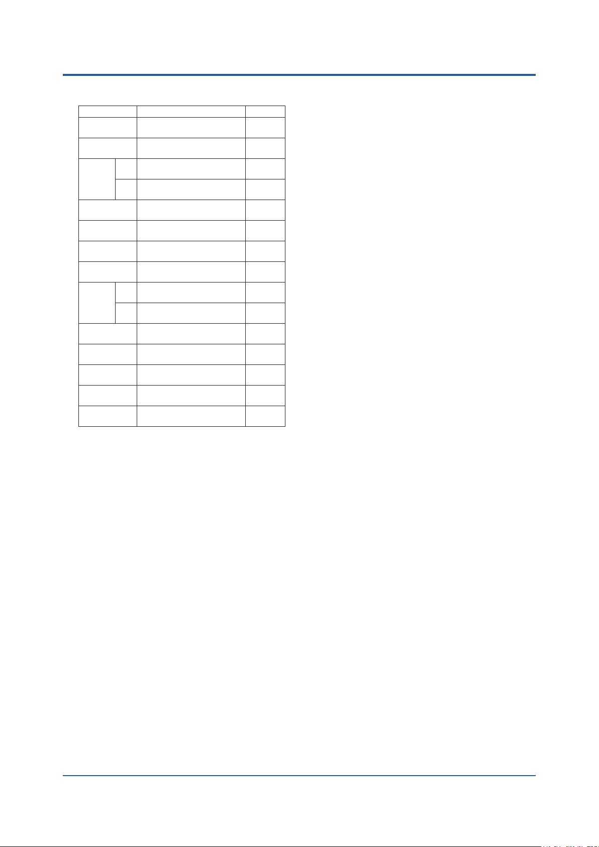
Page 24

6. Physical Properties
Units Min. Typ. Max.
Temperature
Pressure
Dew Point
Water Vapor
Flow
Velocity
Particulate Concentration
Installation location: Indoor Outdoor
Ambient temperature: to ºC
7. General Application & Installation Notes/Comments:
24
All Rights Reserved. Copyright © 2015, Yokogawa Electric Corporation GS 11Y01D01-01EN
Subject to change without notice.
Aug 28, 2020-00
 Loading...