

Page 1

TC10
48
48
48
PV
AT
1411
8 mm max.
Optional
gasket
65 mm min.
2.56 in min.
45
+0.6
mm
1.78
+0.023
in
45
+0.6
mm
1.78
+0.023
in
65 mm mi
n.
2.56 in min.
RS485
TERMINALS
Pin connector
∅
1.4 mm max.
(0.055 in.)
Stripped wire
L: 5.5 mm
(0.21 in.)
L
ELECTRICAL CONNECTIONS
Thermocouple
DI1
OP3
Limiter
OP4
(note)
Output 4: 0-12V DO
Analogue input
mV, V mA
Note: Terminal 4 can be programmed as:
- 0 to 12 V SSR Drive Output (OP4) connecting
the load between terminals 4 and 16;
- 12 Vdc (20 mA) transmitter power supply
connecting the 2 wire transmitter between
terminals 4 and 1; for 3 wire transmitter connect
terminal 4 to transmitter power supply inputand
terminal 1 and2 to transmitter signal output.
Neutral
Line
12VDC
(note)
PV
4 to 20 mA
3 wire transmitter
12VDC
(note)
PV
Pt100Pt1000
100 to 240 Vac
4 to 20 mA
2 wire transmitter
OP1
Output 1: 4-20 mA
Output
1
2
+
_
TC 10 - L
LIMIT CONTROL TYPE
Engineering Manual
Code: IM 05C01E81-12EN
1.3 MOUNTING REQUIREMENTS
This instrument is intended for permanent installation, for
indoor use only, in an electrical panel which encloses the
rear housing, exposed terminals and wiring on the back.
Select a mounting location having the following characteristics:
1. It should be easily accessible;
2. There is minimum vibrations and no impact;
3. There are no corrosive gases;
4. There are no water or other fl uids (i.e. condensation);
5. The ambient temperature is in accordance with the
operative temperature (0 to 50°C);
6. The relative humidity is in accordance with the instrument
specifi cations (20 to 90%);
The instrument can be mounted on panel with a maximum
thickness of 8 mm.
When the maximum front protection (IP65) is
desired, the optional gasket must be mounted.
This is mandatory for FM approval.
First edition:
Nov. 2019
Yokogawa Electric Corporation
2-9-32 Nakacho, Musashino-shi, Tokyo 180-8750 Japan
www.yokogawa.com/ns
1. OUTLINE DIMENSIONS (mm)
1.1 INSTRUMENT DIMENSIONS
1.2 PANEL CUT-OUT
2. CONNECTION DIAGRAM
2.1 GENERAL NOTES ABOUT WIRING
1. Do not run input wires together with power cables.
2. External components (like zener barriers, etc.) connected
between sensor and input terminals may cause errors in
measurement due to excessive and/or not balanced line
resistance or possible leakage currents.
3. When a shielded cable is used, it should be connected at
one point only.
4. Pay attention to the line resistance; a high line resistance
may cause measurement errors.
Yokogawa Electric Corporation - TC10-L - ENGINEERING MANUAL - PAG. 1
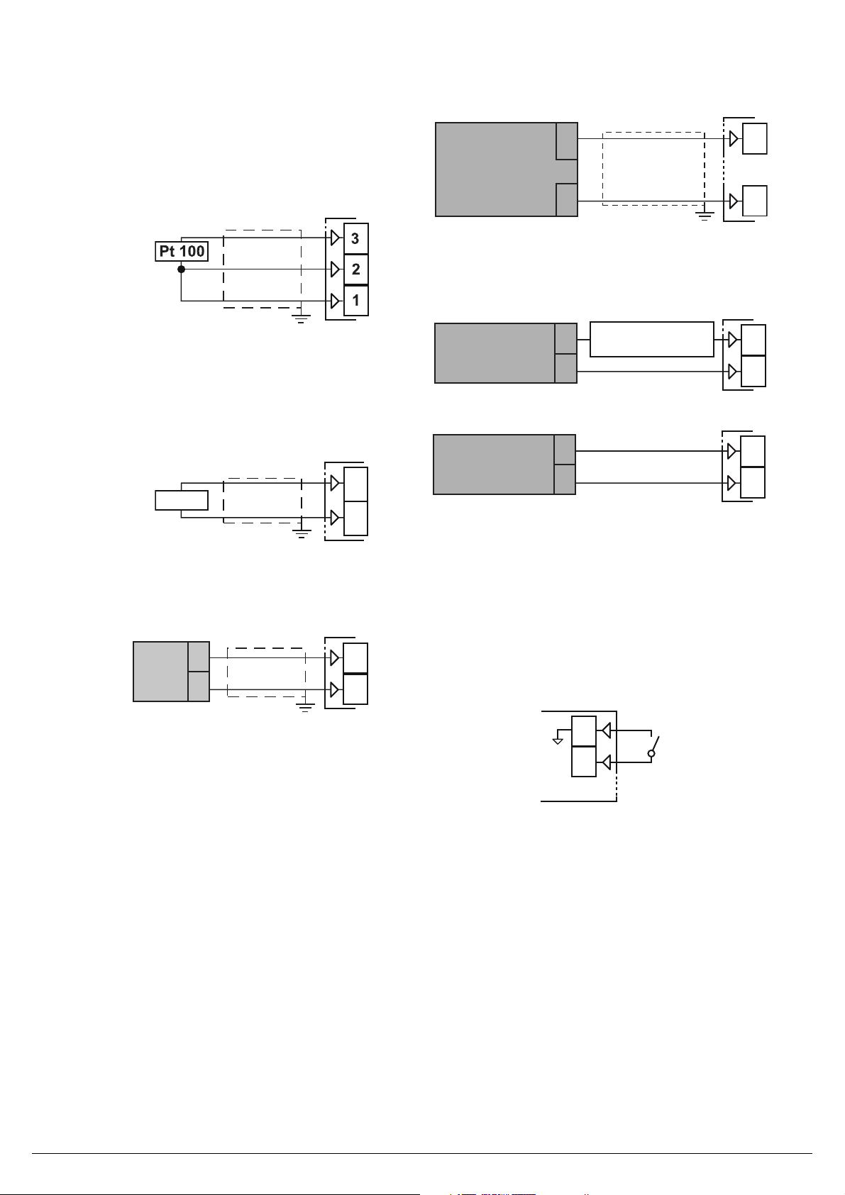
2.2 INPUTS
2.2.1 Termocouple Input
External resistance: 100W max., maximum error 25 µV.
Continuity detection current: 250 nA.
Cold junction: automatic compensation between 0 to 55°C.
Page 2
Cold junction accuracy: 0.04°C/°C after a warm-up of
2
3
Pt1000
mV
V
+
_
+
_
1
2
+
_
4 to 20 mA
Passive
transmitter
4
1
+
_
+
_
1
2
0/4 to 20 mA
Passive
transmitter
_
External
PWS
+
0/4 to 20 mA
Active
transmitter
+
_
+
_
1
2
Digital
Input 1
15
16
20 minutes.
Input impedance: > 1 MW.
Burn out: full scale
Calibration: According to EN 60584-1.
Note: For TC wiring use proper compensating cable
preferable shielded.
2.2.2 RTD Pt 100 Input
Input circuit: Current injection (135 µA).
Line resistance: Automatic compensation up to 20W/wire
with maximum error ±0.1% of the input span.
Calibration: According to EN 60751/A2.
Note: The resistance of the 3 wires must be the same.
2.2.3 RTD Pt 1000 Input
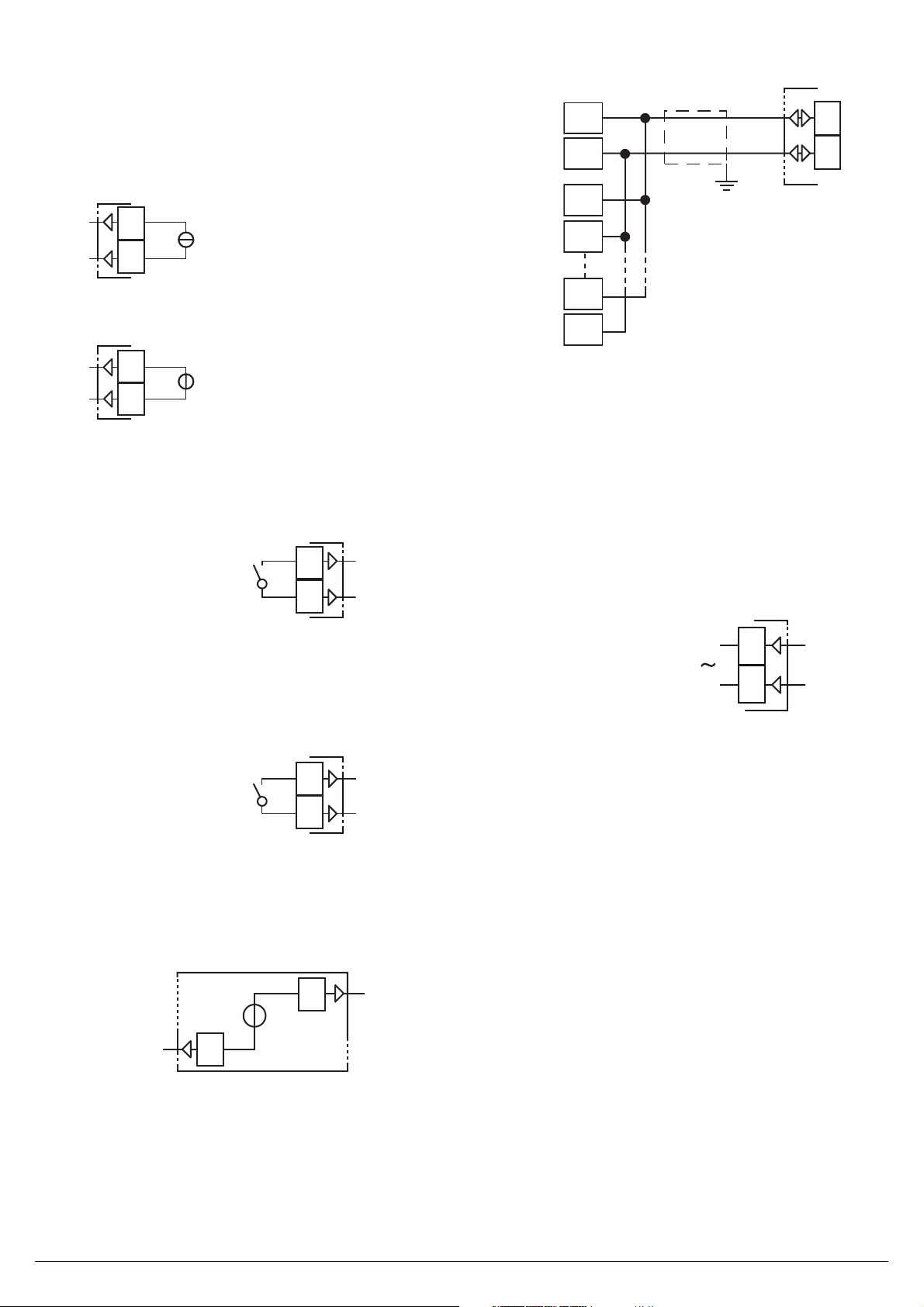
2.2.5 mA Input
0/4 to 20 mA input wiring for passive transmitter
using the auxiliar
Input impedance: < 53W.
Internal auxiliary PWS: 12 VDC (±10%), 20 mA max..
0/4 to 20 mA input wiring for passive transmitter
using an external pws
0/4 to 20 mA input wiring for active transmitter
y pws
Line resistance: Not compensated.
Pt 1000 input circuit: Current injection (15,5 µA).
Pt 1000 calibration: According to EN 60751/A2.
2.2.4 V and mV Input
Input impedance: > 1 MW for mV Input
500 kW for Volt Input.
Yokogawa Electric Corporation - TC10-L - ENGINEERING MANUAL - PAG. 2
2.2.6 Logic Input
Safety notes:
– Do not r
– The instrument needs 150 ms to recognize a contact
status variation;
– Logic inputs are NOT isolated by the measuring input.
A double or reinforced isolation between logic inputs and
power line must be assured by the external elements.
Logic inputs driven by dry contact
Maximum contact resistance: 100W.
Contact rating: DI1 = 10 V, 6 mA;
un logic input wiring together with power cables;
2.3 OUTPUTS
Safety notes:
– To avoid electrical shocks, connect power line at last.
– For supply connections use No. 16 AWG or larger wires
rated for at last 75°C.
– Use copper conductors only.
– SSR outputs are not isolated. A reinforced isolation must
be assured by the external solid state relays.
– For SSR, mA and V outputs if the line length is longer than
30 m use a shielded wire.
– Do not short-circuit the terminals of the SSR output.
WARNING! Before connecting the output actuators,
we recommend to confi gure the parameters to
Page 3
suit your application (e.g.: input type, Control
mA
+
-
7
8
V
+
-
7
8
C
NO
13
14
C
NO
11
12
SSR
+
-
4
Out4
4
16
D +
D -
D +
D -
D +
D -
D +
D -
RS-485
5
6
Power Supply
9
10
Neutral
Line
strategy, alarms, etc.).
2.3.1 Output 1 (OP1)
Function: retransmission
Output type: isolated output
Current Analog Output
2.4 SERIAL INTERFACE
mA output:
0/4... 20 mA, galvanically isolated, RL max. 600W.
Voltage Analog Output
V output: 0/2... 10 V
, galvanically isolated
2.3.2 Output 2 (OP2)
Function: limiter output
Relay Output
Contact rating: • 2 A /250 V cosϕ = 1;
• 1 A /250 V cosϕ = 0.4.
Operation: 1 x 10⁵.
2.3.3 Output 3 (OP3)
Relay Output
Contact rating: • 2 A /250 V cosϕ = 1;
• 1 A /250 V cosϕ = 0.4.
Operation: 1 x 10⁵.
, RL min.: 500W.
Interface type: Isolated (50 V) RS-485;
Voltage levels: According to EIA standard;
Protocol type: Modbus RTU;
Byte format: 8 bit with no parity;
Stop bit: 1 (one);
Baud rate:
Address: Programmable between 1 to 254.
Notes: 1. RS-485 interface allows to connect up to 30
2. The cable length must not exceed 1.5 km at
Programmable between 1200 to 38400 baud;
devices with one remote master unit.
9600 baud.
2.5 POWER SUPPLY
Supply Voltage: 100 to 240 VAC (-15 to +10%).
Notes: 1. Before connecting the instrument to the power
line, make sure that line voltage is equal to the
voltage shown on the identifi cation label;
2. The polarity of the power supply has no importance;
3. The power supply input is NOT fuse protected.
Please, provide a T type 1A, 250 V fuse externally.
2.3.4 Output 4 (OP4)
SSR Output
Logic level 0: Vout < 0.5 VDC;
Logic level 1: 12 V ±20%, 20 mA max..
Note: Overload protected.
Yokogawa Electric Corporation - TC10-L - ENGINEERING MANUAL - PAG. 3
Page 4

3. TECHNICAL CHARACTERISTICS
4. MODEL AND SUFFIX CODES
3.1 TECHNICAL SPECIFICATION
Case:
Front protection: IP 65 (when the optional panel gasket is
mounted) for indoor locations according to EN 60070-1;
Terminals protection: IP 20 according to EN 60070-1;
Installation: Panel mounting;
Terminal block:
0.25 to 2.5 mm2 (AWG22 to AWG14) with connection diagram,
tightening torque 0.5 Nm;
Dimensions: 48 x 48, depth 73 mm, (1.89 x 1.89 x 2.87 in.)
Panel cutout: 45[-0, +0.6] x 45[-0, +0.6] mm
(1.78[- 0.000, +0.023] x 1.78[- 0.000, +0.023] in.)
Weight: 180 g max..
Power supply: 100 to 240 VAC (-15 to +10% of the
nominal value);
Power consumption: 6.0 VA max. (100 to 240 VAC);
Insulation voltage: 2300 V rms according to EN 61010-1;
Display updating time: 500 ms;
Sampling time: 130 ms;
Resolution: 30000 counts;
Total Accuracy: ±0.5% F.S.V. ±1 digit @ 25°C of room
temperature;
Plastic, self-extinguishing degree: V-0 according to UL 94;
16 screw terminals for cables of
Model Code
TC10 -L
Fixed code -L Always "-L"
Power supply H 100 to 240 VAC
Fixed code C Always "C"
Retransmission
Limit control output R limit control relay output
Alarm output 1 - 2
Fixed code D
Serial communication
Fixed code F Always “F”
Option Code /GK Panel gasket for IP65
Suffix codes Description
oCo o oDo
N None
A PV retrans. output 4 to 20 mA
F Temperature Controller
N None
R
S RS485 Modbus
N None
Alarm output:2 Points (OT3 relay
+ OT4 SSR drive)
Always "D"
Electromagnetic compatibility and safety requirements
Compliance: directive EMC 2004/108/CE (EN 61326-1),
directive LV 2006/95/CE (EN 61010-1),
UL 61010-1 CSA 61010-1;
Note: During the test, the instrument continues to operate at
the measurement accuracy within specifi cation.
Installation category: II;
Pollution category: 2;
Temperature drift: It is part of the global accuracy;
Operating temperature: 0 to 50°C (32 to 122°F);
Storage temperature: -20 to +70°C (-4 to +158°F);
Humidity: 20 to 95% RH, not condensing.
Yokogawa Electric Corporation - TC10-L - ENGINEERING MANUAL - PAG. 4
Page 5
5. CONFIGURATION PROCEDURE
SP
HYS
PV
(A) (B) (C) (A) (B)(D)
EXCEEDED
LAMP
OUT
LAMP
lit
off
OUTPUT
RELAY
confirmation
(accepted)
confirmation
(not accepted)
lit
off
Energized
De-energized
OFF
OFFOFF
Lit
OFF
Lit
OFF
ON
OFF
Lit
OFF
Power
ON
OFF
SP
HYS
PV
(A) (B) (D)(C)
EXCEEDED
LAMP
OUT
LAMP
lit
off
OUTPUT
RELAY
confirmation
(accepted)
lit
off
Energized
De-energized
OFF
OFF
OFF
Lit
ON
OFF
Lit
OFF
Power
ON
OFF
OFF
ON
OFF
5.1 INTRODUCTION
When the instrument is powered, it starts immediately
to work according to the parameters values loaded in its
memory.
The instrument behaviour and its performance are governed
by the value of the stored parameters.
At the fi rst start up the instrument will use a “default” parameter set (factory parameter set); this set is a generic one
(e.g. a TC J input is programmed).
WARNING! Before connecting the output actuators, we
recommend to confi gure the parameters to
suit your application (e.g.: input type, Control
strategy, alarms, etc.).
To change these parameters you need to enter the “Confi guration mode”.
5.2 INSTRUMENT BEHAVIOUR AT POWER
ON
At power ON the instrument can operate in two different
mode according to the value assigned to [34] r.md parameter [34] r.md equal to 0
(Limit output is de-energized at power on in any cases.)
The output relay is always de-energized (opened) at poweron,even if PV does not exceed SP(A). The output (OUT)
display lamp is lit. If thePV does not exceed SP, after the
confi rming operation, output relay will be energized (closed)
and the output (OUT) display lamp turns off .
5.3 HOW TO ENTER THE
“CONFIGURATION MODES”
The confi guration procedure allows to take advantage of all
instrument features.
The instrument have one complete parameter set.
We call this set “confi guration parameter set” (or
“confi guration parameters”).
The access to the confi guration parameters is
password.
5.3.1 Complete confi guration procedure
The confi guration parameters are collected in various
groups. Every group defi nes all parameters related with a
specifi c function (e.g.: control, alarms, output functions).
1. Push the button for more than 3 seconds. The upper
display will show PASS while the lower display will show 0.
2. Using and buttons set the programmed password.
Notes: 1. The factory default password for confi guration
parameters is equal to 30.
3. Push the button
If the password is correct the display will show the acronym
protected by a
[34] r.md equal to 1(Limit output is de-energized at power on
in any cases.)The state of output relay is energized (closed)
and the output (OUT) display lamp turns off if the PV does
not exceed SP at power-on.
of the fi rst parameter group preceded by the symbol:
In other words the upper display will show:
]inp
]
.
(group of the Input parameters).
The instrument is in confi guration mode.
5.4 HOW TO EXIT THE “CONFIGURATION
MODE”
Push button for more than 3 seconds, the instrument will
come back to the “standard display”.
5.5 KEYBOARD FUNCTIONS DURING
PARAMETER CHANGING
A short press allows to exit from the current parameter
group and select a new parameter group.
A long press allows you to close the confi guration
parameter procedure (the instrument will come back
to the “standard display”).
When the upper display is showing a group and the
lower display is blank, this key allows to enter in the
selected group.
When the upper display is showing a parameter and
Yokogawa Electric Corporation - TC10-L - ENGINEERING MANUAL - PAG. 5
Page 6

the lower display is showing its value, this key allows
to store the selected value for the current parameter
and access the next parameter within the same group.
Allows to increase the value of the selected parameter.
Allows to decrease the value of the selected parameter.
+ These two keys allow to return to the previous
group. Proceed as follows:
Push the button and maintaining the pressure,
then push the button; release both the buttons.
Note: The group selection is cyclic as well as the selection
of the parameters in a group.
5.6 FACTORY RESET - DEFAULT
PARAMETERS LOADING PROCEDURE
Sometime, e.g. when you re-confi gure an instrument
previously used for other works or from other people or when
you have made too many errors during confi guration and
you decided to re-confi gure the instrument, it is possible to
restore the factory confi guration.
This action allows to put the instrument in a defi ned
condition (the same it was at the fi rst power ON).
The default data are those typical values loaded in the
instrument prior to ship it from factory.
To load the factory default parameter set, proceed as follows:
1. Press the
display will show PASS while the lower display shows 0;
2. Using
3. Push
4. The instrument will turn OFF all LEDs for a few seconds,
then the upper display will show dFLt (default) and then
all LEDs are turned ON for 2 seconds. At this point the
instrument restarts as for a new power ON.
The procedure is complete.
Note: The complete list of the default parameters is available
in Appendix A.
button for more than 5 seconds. The upper
and buttons set the value -481;
button;
5.7 CONFIGURING ALL THE PARAMETERS
In the following pages we will describe all the parameters of
the instrument. However, the instrument will only show the
parameters applicable to its hardware options in accordance
with the specifi c instrument confi guration (i.e. setting AL1t
[Alarm 1 type] to nonE [not used], all parameters related to
alarm 1 will be skipped).
]inP Group - Main and auxiliary input confi guration
[1] SEnS - Input type
Available: Always.
Range: • When the code of the input type is equal to c
(see paragraph “How to order”).
J TC J (-50... +1000°C/-58... +1832°F);
crAL TC K (-50... +1370°C/-58... +2498°F);
S TC S (-50... 1760°C/-58... +3200°F);
r TC R (-50... +1760°C/-58... +3200°F);
t TC T (-70... +400°C/-94... +752°F);
n TC N (-50...1300°C/-58...2372°F);
Pt1 RTD Pt 100 (-200... 850°C/-328... 1562°F);
Pt10 RTD Pt 1000 (-200... 850°C/-328... 1562°F);
0.60 0... 60 mV linear;
12.60 12... 60 mV linear;
0.20 0... 20 mA linear;
4.20 4... 20 mA linear;
0.5 0... 5 V linear;
1.5 1... 5 V linear;
0.10 0... 10 V linear;
2.10 2... 10 V linear.
Notes: 1. When a TC input is selected and a decimal fi gure
is programmed (see the next parameter) the max.
displayed value becomes 999.9°C or 999.9°F.
2. Every change of the SEnS parameter will
produces a change of the related parameter and
in particular:
• [7] bS (PV bias) will be forced to zero
• [11] Ao1L and [12] Ao1H (when the analog
retransmission is present) will be forced to the
Ex.Range limits.
• [13] AL1 and [30] AL2 will be forced to :
– for an absolute maximum alarm, them will be
forced to the maximum input span
– for an absolute minimum alarm, them will be
forced to the minimum input span
– for all other alarm, them will be forced to zero
• [14] HAL1 and [31] HAL2 will be forced equal
to the 0.5% of the input span
• [28] AL2L extended limit low
• [29] AL2H extended limit high
• [35] HYS will be forced equal to 0.05 % of the
input span
• [37] SPLL and [38] SPHL
• [39] SP
• the CAL group will be reset [51]A.L.P, [52]
A.L.O, [53] A.H.P, [54] A.H.O
[2] dP - Decimal point position
Available: Alw
Range: 0 to 3 when [1] SenS = Linear input;
0 or 1 when [1] SenS different from linear input.
Note: Every change of the dP parameter setting will produce
a change of the parameters related with it (e.g.: set
points, proportional band, etc.).
ays.
[3] SSc - Initial scale read-out for linear inputs
Available: When a linear input is selected b
Range: -1999 to 9999.
Notes: 1. SSc allows the scaling of the analog input to set
the minimum displayed/measured value.
The instrument will show a measured value up to
5% less than SSc value and then it will show an
underrange error.
2. It is possible to set a initial scale read-out higher
than the full scale read-out in order to obtain a
reverse read-out scaling.
E.g.:
0 mA = 0 mBar and 20 mA = -1000 mBar (vacuum).
y [1] SenS.
[4] FSc - Full scale read-out for linear input
Available: When a linear input is selected by [1] SenS.
Range: -1999 to 9999.
Notes: 1. Fsc allows the scaling of the analog input to set
the maximum displayed/measured value.
The instrument will show a measured value up to
5% higher than [4] FSc value and then it will show
Yokogawa Electric Corporation - TC10-L - ENGINEERING MANUAL - PAG. 6
Page 7

an overrange error.
2. It is possible to set a full scale read-out lower
than the initial scale read-out in order to obtain a
reverse read-out scaling.
E.g.:
0 mA = 0 mBar and 20 mA = -1000 mBar (vacuum).
[5] unit - Engineering unit
Available: When a temperature sensor is selected by [1]
SenS parameter.
Range: °C = Celsius;
°F = Fahrenheit.
[6] FiL - Digital fi lter on the measured value
Available: Alw
Range: oFF (No fi lter);
0.1 to 20.0 s.
Note: This is a fi rst order digital fi lter applied on the
measured value. For this reason it will affect the
measured value but also the control action and the
alarms behaviour.
[7] bS -
Available: Always.
Range: In Engineering unit, it is programmable from -100 to
ays.
PV input bias
100 % of the input span
[8] di.A - Digital Input Action
Available: Always.
Range: 0 = DI1 Direct action,
1 = DI1 Reverse action,
]out Gr
oup - Output parameters
[9] o1.t - Out 1 type
Available: When the out 1 is a linear output.
Range: 0.20 0 to 20 mA;
4.20 4 to 20 mA;
0.10 0 to 10 V;
2.10 2 to 10 V.
[10] o1F - Out 1 function
Available: Alw
Range: • When the out 1 is a linear output:
nonE =
r.inP = Measured value Analog retransmission.
r.Err = Analog retransmission of the measured
r.SP = Analog retransmission of the operative set
r.SEr = Analog retransmission of a value coming
ays.
Output not used. With this setting the status
of this output can be driven directly from
serial link;
error (PV-SP);
point;
from serial link;
[11] Ao1L - Initial scale value of the analog
retransmission
Available: When Out 1 is a present
Rang
e: -1999 to [12] Ao1H.
[12] Ao1H
- Full scale value of the analog
retransmission
Available: When Out 1 is present
Range: [11] Ao1L to 9999.
[13] o3F - Out 3 function
Available: When the instrument has out 3 option.
Range: nonE = Output not used. With this setting the status
of the this output can be driven directly
from serial link;
AL = Alarm output;
or.bo = Out-of-range or burn out indicator;
P.FAL = Power failure indicator;
bo.PF = Out-of-range, burn out and Power failure
indicator;
[14] o3AL - Alarms linked up with Out 3
Available: When [13] o3F = AL.
Range: 0 to 15 with the following rule:
+1 = Alarm 1;
+2 = Alarm 2;
+4 = Sensor break (burn out);
+8 = Overload on Out 4 (short circuit on out 4);
[15] o3Ac - Out 3 action
Available: when [13] o3F is diff
Range: dir = Direct action;
rEU = Reverse action;
Notes: 1. Direct action: the output repeats the status of the
driven element. Example: the output is an alarm
output with direct action. When the alarm is ON,
the relay will be energized (logic output 1).
2. Reverse action: the output status is the opposite
of the status of the driven element. Example:
the output is an alarm output with reverse
action. When the alarm is OFF, the relay will be
energized (logic output 1). This setting is usually
named “fail-safe” and it is generally used in
dangerous process in order to generate an alarm
when the instrument power supply goes OFF or
the internal watchdog starts.
erent from “nonE”.
[16] o4F - Out 4 function
Available: Alw
Range: nonE = Output not used. With this setting the status
AL = Alarm output;
or.bo = Out-of-range or burn out indicator;
P.FAL = Power failure indicator;
bo.PF = Out-of-range, burn out and Power failure
On = Output ever ON (it is used as auxiliary
ays
of the this output can be driven directly
from serial link.
indicator;
power supply for TX).
[17] o4AL - Alarms linked up with Out 4
Available: When [16] o4F = AL.
Rang
e: 0 to 7 with the following rule.
+1 = Alarm 1;
+2 = Alarm 2;
+4 = Sensor break (burn out);
[18] o4Ac - Out 4 action
Available: When [16] o4F is diff
Range: dir = Direct action;
rEU = Reverse action;.
erent from “nonE”.
Yokogawa Electric Corporation - TC10-L - ENGINEERING MANUAL - PAG. 7
Page 8

For more details see [15] o3.Ac parameter.
LoAb
OUT
AL1
AL1
PV
HAL1
time
HiAb
offoffoff
OUT
AL1
AL1
PV
HAL1
time
offoffoff
ON ON ON ON
LHAo
PV
AL1H
HAL1
time
offoffoff
LHdo
OUT
AL1
AL1L
HAL1
PV
AL1H
SP
HAL1
time
OUT
AL1
-AL1L
HAL1
offoffoff
ON ON ON ON
PWR ON
AL1
PV
time
offoff
Ab1 = +1
Ab1 = +0
offoff
ON ON
ON
Sp2
Sp1
PV
time
Ab1 = +8
Ab1 = +0
ON
offoff
AL1
offoffoff
AL1
ON
ON ON
ON
]AL1 Group - Alarm 1 parameters
[19] AL1t - Alarm 1 type
Available: Always.
Range:
nonE = Alarm not used;
LoAb = Absolute low alarm;
HiAb = Absolute high alarm;
LHAo = Absolute band alarm with alarm indication
out of the band;
LHAi = Absolute band alarm with alarm indication
inside the band;
SE.br = Sensor break;
LodE = Deviation low alarm (relative);
HidE = Deviation high alarm (relative);
LHdo = Relative band alarm with alarm indication
out of the band;
LHdi = Relative band alarm with alarm indication
inside the band.
Notes: 1. The relative and deviation alarms are “relative” to
the operative set point value.
2. The (SE.br) sensor break alarm will be ON when
the display shows ---- indication.
[20] Ab1 - Alarm 1 function
Available: When [28] AL1t is diff
Range: 0 to 3 with the following rule:
+1 = Not active at power up;
+2 =
Relative alarm not active at set point change.
Notes: 1. The “not active at power up” selection allows to
inhibit the alarm function at instrument power up
The alarm will be automatically enabled when the
measured value reaches, for the fi rst time, the
alarm threshold ±hysteresis (in other words, when
the initial alarm condition disappears).
2. A relative alarm not active at set point change” is
an alarm that masks the alarm condition after a
set point change until process variable reaches
the alarm threshold ±hysteresis.
Yokogawa Electric Corporation - TC10-L - ENGINEERING MANUAL - PAG. 8
erent from “nonE”.
3. The instrument does not store in EEPROM the
alarm status. For this reason, the alarm status
will be lost if a power down occurs.
[21] AL1L - For High and low alarms it is the low
limit of the AL1 threshold
-
For band alarm it is low alarm threshold
Available: When [19] AL1t is different from “nonE”.
Range: From -1999 to [22] AL1H engineering units.
[22] AL1H
- For High and low alarms, it is the high
limit of the AL1 threshold
- For band alarm, it is the high alarm
threshold
Available: When [19] AL1t is diff
Range: From [21] AL1L to 9999 engineering units.
erent from “nonE”.
[23] AL1- Alarm 1 threshold
Available: When:
[19] AL1t = LoAb - Absolute low alarm;
[19] AL1t = HiAb - Absolute high alarm;
[19] AL1t = LodE - Deviation low alarm (relative);
[19] AL1t = HidE - Deviation high alarm (relative).
Range: From [21] AL1L to [22] AL1H engineering units.
[24] HAL1 - Alarm 1 hysteresis
Available: When [19] AL1t is diff
Range: 1 to 9999 engineering units.
Notes: 1.
The hysteresis value is the difference between
the Alarm threshold value and the point the Alarm
automatically resets.
2. When the alarm threshold plus or minus the
hysteresis is out of input range, the instrument
will not be able to reset the alarm.
Example: Input range 0 to 1000 (mBar).
– Set point equal to 900 (mBar);
– Deviation low alarm equal to 50 (mBar);
– Hysteresis equal to 160 (mBar) the theoretical reset point is
900 - 50 + 160 = 1010 (mBar) but this value is out of range.
The reset can be made only by turning the instrument
OFF, removing the condition that generate the alarm and
then turn the instrument ON again;
– All band alarms use the same hysteresis value for both
thresholds;
– When the hysteresis of a band alarm is bigger than the
programmed band, the instrument will not be able to reset
the alarm.
Example: Input range 0 to 500 (°C).
– Set point equal to 250 (°C);
– Relative band alarm;
– Low threshold equal to 10 (°C);
– High threshold equal to 10 (°C);
– Hysteresis equal to 25 (°C).
erent from “nonE”.
Page 9

[25] AL1d - Alarm 1 delay
SP
HYS
PV
(A) (B) (C) (A) (B)(D)
EXCEEDED
LAMP
OUT
LAMP
lit
off
OUTPUT
RELAY
confirmation
(accepted)
confirmation
(not accepted)
lit
off
Energized
De-energized
OFF
OFFOFF
Lit
Lit
OFF
Lit
ON
OFF
ON
OFF
Lit
OFF
Available: When [19] AL1t is different from “nonE”.
Range: From oFF (0) to 9999 seconds.
Note: The alarm goes ON only when the alarm condition
persists for a time longer than [25] AL1d time but the
reset is immediate.
]AL2 Group - Alarm 2 parameters
[26] AL2t - Alarm 2 type
Available: A
Range:
Note: The relative alarm are “relative” to the current set
ways.
nonE = Alarm not used;
LoAb = Absolute low alarm;
HiAb = Absolute high alarm;
LHAo = Absolute band alarm with alarm indication
out of the band;
LHAi = Absolute band alarm with alarm indication
inside the band;
SE.br = Sensor break;
LodE = Deviation low alarm (relative);
HidE = Deviation high alarm (relative);
LHdo = Relative band alarm with alarm indication
out of the band;
LHdi = Relative band alarm with alarm indication
inside the band.
point.
reset is immediate.
]rEG gr
oup - Control parameters
[33] Hi.Lo - Control type:
Available: Always.
Range:
Hi = Hi limit;
Lo = Low limit
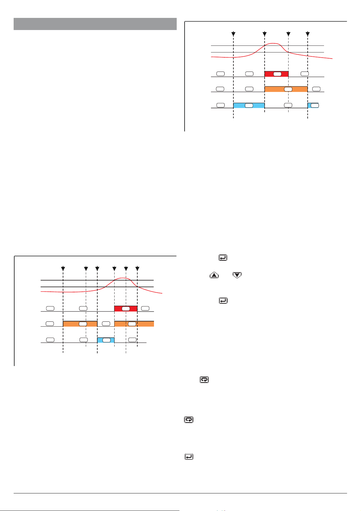
High limit control
When a measured value (PV) exceeds a set point
(SP),“EXCEEDED” [EX]lamp lights, “OUT” lamp turns ON
and the limit output relay (Out 2) is de-energized.
“EXCEEDED” [EX] lamp turns off when PV goes into normal
condition, while the output [OUT] display lamp stays on as
it is (b). The output [OUT] display lamp turns off when a
confi rming operation (rearm) is done by an operator.
The way to confi rm are: pressing
(according to the <<diS>> parameter setting).
The confi rming operation is not accepted during PV exceeds
SP (D) (during EXCEEDED lamp lights*). State of output
relay is de-energized whenever “OUT” lamp is on.
.
key or by DI1
[27] Ab2 - Alarm 2 function
Available: When [26] AL2t is diff
Range: 0 to 3 with the following rule:
+1 = Not active at power up;
+2 =
[28] AL2L
Relative alarm not active at set point change.
- For High and low alarms it is the low
erent from “nonE”.
limit of the AL2 threshold
- For band alarm it is low alarm threshold
Available: When [26] AL2t is different from “nonE”.
Range: -1999 to [29] AL2H engineering units.
[29] AL2H
- For High and low alarms it is the high
limit of the AL2 threshold
-
For band alarm it is high alarm threshold
Available: When [26] AL2t is different from “nonE”.
Range: From [28] AL2L to 9999 engineering units.
[30] AL2 - Alarm 2 threshold
Available: When:
[26] AL2t = LoAb Absolute low alarm;
[26] AL2t = HiAb Absolute high alarm;
[26] AL2t = LodE Deviation low alarm (relative);
[26] AL2t = HidE Deviation high alarm (relative).
Range: From [28] AL2L to [29] AL2H engineering units.
[31] HAL2 - Alarm 2 hysteresis
Available: When [26] AL2t is diff
Range: 1 to 9999 engineering units.
Note: For other details see [24] HAL1 parameter.
erent to “nonE” or [26] AL2t
is different from “SE.br”.
When the EXCEED lamp is ON but PV is lower than SP, the
upper display will be in green value and it shows that the PV
is in the hysteresis area.
Low limit control
When a measured value (PV) exceeds a setpoint (SP),
“EXCEEDED” lamp (c) lights, and “OUT” lamp (b) turns ON .
The limit output relay is de-energizedthen.
“EXCEEDED” lamp turns off when PV goes into normal
condition, while the output (OUT) display lamp stays on
as it is. The output (OUT) display lamp turns off when a
confi rming operation is done by an operator.
The way to confi rm are:
- pressing
key or
- by DI1 (according to the <<diS>> parameter setting).
The confi rming operation is not accepted during PV exceeds
SP (D) (during EXCEEDED lamp lights*). State of output
relay is de-energized whenever “OUT” lamp is on.
[32] AL2d - Alarm 2 delay
Available: When [26] AL2t type is diff
Range: From oFF (0) to 9999 seconds.
Note: The alarm goes ON only when the alarm condition
persist for a time longer than [32] AL2d time but the
Yokogawa Electric Corporation - TC10-L - ENGINEERING MANUAL - PAG. 9
erent form “nonE”.
Page 10

SP
HYS
PV
(A) (B) (C) (A) (B)(D)
EXCEEDED
LAMP
OUT
LAMP
lit
off
OUTPUT
RELAY
confirmation
(accepted)
confirmation
(not accepted)
lit
off
Energized
De-energized
OFF
OFFOFF
Lit
Lit
OFF
Lit
ON
OFF
ON
OFF
Lit
OFF
When the EXCEED lamp is ON but PV is Higher than SP,
the upper display will be in green value and it shows that the
PV is in the hysteresis area.
[34] r.md – Limit output status at power ON (Re-
start mode)
Available: A
Range: 0 = limit output is ON in any cas
[35] HyS – Hysteresis of the control output
Available: Available: always
Range: In engineering unit from 0.0 to 100 % of the input
vailable: always
1 = Limit output is OFF at power on when PV
doesn’t exceed SP.
span
[36] oP.SL – Operating display selection.
Available: A
vailable: always
Range:
Range: PU.SP = (0) PV (upper display) and SP (lower
display)
PU = (1) SP only (lower display)
Note: When you change the [37] SPLL value, the nstrument
checks the local set points (SP parameters). If SP
is out of this range, the instrument forces it to the
maximum acceptable value
[37] SPLL – Minimum set point value
Available: A
Range: from -1999 to [38] SPHL
Note: When you change the [37] SPLL value, the instrument
vailable: always
checks the local set points (SP parameters). If SP
is out of this range, the instrument forces it to the
minimum acceptable value.
[38] SPHL – Maximum set point value
Available: Available: always
Range: from [37] SPLL to 9999.
[39] SP - Set point.
Available: A
Range: from [37] SPLL to [38] SPHL
vailable: always
[40] diS– the way of confi rming operation
Available: Available: always
Range: but = by keyboard
di = by digital input
[41] tim – time duration of the last exceeded period.
Available: A
Range: from 00.00 to 99.59 (HH.mm).
vailable: always but it is a read only parameter.
[42] Hi- maximum measured value
Available: Available: when [33] Hi.Lo = Hi (high limit) but it is
a read only parameter.
Range: Engineering unit within the input range
[43] Lo – minimum measured value
Available: A
Range: Engineering unit within the input range.
vailable: when [33] Hi.Lo = Lo (low limit) but it is
a read only parameter.
]PAn group - Operator HMI
[44] PAS2 - Level 2 password:
Available: Always.
Range: oFF = Level 2 not protected by password
(as level 1 = Operator level) 1 to 200.
[45] PAS3
- Level 3 password:
Complete confi guration level
Available: Alw
Range: 3 to 200.
Note: Setting [44] PAS2 equal to [45] PAS3, the level 2 will
be masked.
ays.
[46] di.CL - Display color
Available: Always.
Range: 0 = the display color is used to show the
Exceed condition.
When no exceed condition is present, the
upper display will be green.
when [33] Hi.Lo = Hi (high limit ) and PV >
SP the upper display will be red.
when [33] Hi.Lo = Lo (low limit ) and PV <
SP the upper display will be red.
1 = Display red (fi x);
2 = Display green (fi x);
3 = Display orange (fi x).
[47] diS.t - Display time out
Available: Alw
Range: oFF = The display is ever ON;
0 (OFF) to 99.59 minutes and seconds.
Note: This function allows to turn OFF the display when no
alarm is present and no action is made on the instrument.
When diS.t is different from OFF and no button is
pressed for more than the programmed time out, the
display goes OFF and only 4 segments of the less
signifi cant digit are turned ON in sequence in order to
show that the instrument is working correctly.
If an alarm occurs or a button is pressed, the display
will come back to the normal operation.
ays.
]Ser group - Serial link parameter
[48] Add - Instrument address
Available: Always.
Range: oFF = Serial interface not used;
1 to 254.
[49] bAud - Baud rate
Available: When [48] Add diff
Range: 1200 = 1200 baud;
2400 = 2400 baud;
erent from oFF.
Yokogawa Electric Corporation - TC10-L - ENGINEERING MANUAL - PAG. 10
Page 11

9600 = 9600 baud;
AH.P 100°C
AH.o = 2
AL.o = -1
AH.P 10°C
Real curve
Modified curve
19.2 = 19200 baud;
38.4 = 38400 baud.
]CAL group - User calibration group
This function allows to calibrate the complete measuring
chain and to compensate the errors due to:
– Sensor location;
– Sensor class (sensor errors);
– Instrument accuracy.
[50] A.L.P - Adjust Low Point
Available: Alw
Range: -1999 to (A.H.P - 10) engineering units.
Note: The minimum difference between A.L.P and A.H.P is
equal to 10 Engineering Units.
[51] A.L.o - Adjust Low Offset
Available: Always.
Range: -300 to +300 engineering units.
[52] A.H.P - Adjust High Point
Available: Alw
Range: From (A.L.P + 10) to 9999 engineering units.
Note: The minimum difference between A.L.P and A.H.P is
equal to 10 Engineering Units.
ays.
ays.
• Push
button for more than 3 s. The instru-
ment will come back to the “standard display”.
[53] A.H.o - Adjust High Offset
Available: Always.
Range: -300 to +300 Engineering Units.
Example: Environmental chamber with an operative range:
10 to 100°C.
1. Insert in the chamber a reference sensor connected with
a reference instrument (usually a calibrator).
2. Start the control of the instrument, and set a set point equal to
the minimum value of the operative range (e.g.: 10°C). When
the temperature in the chamber is steady, take note of the
temperature measured by the reference system (e.g.: 9°C).
3. Set [50] A.L.P = 10 (low working point) and [140] A.L.o = -1
(it is the difference between the reading of the instrument
and the reading of the reference system). Note that after
this set the measured value of the instrument is equal to
the measured value of the reference system.
4. Set a set point equal to the maximum value of the
operative range (e.g. 100°C). When the temperature
in the chamber is steady, take note of the temperature
measured by the reference system (e.g. 98°C).
5. Set [52] A.H.P = 100 (low working point) and [142]
A.H.o = +2
instrument and the reading of the reference system). Note
that after this set the measured value of the instrument is
equal to the measured value of the reference system.
(it is the difference between the reading of the
The most important step of the confi guration procedure is
completed.
In order to exit from confi guration parameter procedure,
proceed as follows:
• Push
button.
Yokogawa Electric Corporation - TC10-L - ENGINEERING MANUAL - PAG. 11
Page 12

6. OPERATIVE MODES
PV
SP
Process Value
(in eng. units)
Set Point
(a)
(Editing mode)
Limit
Control
High
Limiter
Exceeded
indication
EX
OUT
PK
HI AL1 AL2
TC10-L
Output
(b)
(c)
(d)
(e)
SP
HYS
PV
(A) (B) (C) (A) (B)(D)
EXCEEDED
LAMP
OUT
LAMP
lit
off
OUTPUT
RELAY
confirmation
(accepted)
confirmation
(not accepted)
lit
off
Energized
De-energized
OFF
OFFOFF
Lit
Lit
OFF
Lit
ON
OFF
ON
OFF
Lit
OFF
SP
HYS
PV
(A) (B) (C) (A) (B)(D)
EXCEEDED
LAMP
OUT
LAMP
lit
off
OUTPUT
RELAY
confirmation
(accepted)
confirmation
(not accepted)
lit
off
Energized
De-energized
OFF
OFFOFF
Lit
Lit
OFF
Lit
ON
OFF
ON
OFF
Lit
OFF
The TC10-L is an FM (both FM3545 and FM3810) approved
limit controller that can be confi gured either as a high limit or
as a low limit controller by a user.
The relay of the output 2 operates in fail-safe mode (relay
de-energized during shutdown condition) and latching mode.
OUT 2 turns OFF (in this document this condition will be
named shutdown) when:
The instrument is confi gured as a high limiter (Hi.Lo = Hi)
and the measured value is greater than limiter threshold
[“SP” parameter] or.
The instrument is confi gured as a low limiter (Hi.Lo = Lo)
and the measured value is lower than limiter threshold.
Out 2 remains OFF until the condition which generated the
shutdown, no longer exists and the Confi rming action (rearm) has been performed.
During a shutdown (Out 2 is OFF) the upper display will be
red.
Confi rming action (rearm) can be performed in two different
way:
- by pressing the
key [when “diS” parameter is set to
“but”] but it will be accepted only when the condition which
generated the shutdown, no longer exists (EX lamp is OFF)
and the set point is shown on the lower display (see “normal
display” in “Navigation access”)
- by momentarily closing the digital input (by an external dry
contact) [when diS parameter is set to “di”] but it will be accepted only when the condition which generated the shutdown, no longer exists.
We defi ne also that the time duration of the shutdown condition, stored by the instrument, will be the time from Out 2
goes OFF (shutdown start) and the condition that generate
the shutdown no longer exists.
The confi rmation action is not part of this time count.
The time duration of the shutdown condition and max/min
measured values are stored in memory and available for
viewing (see “navigation access”) until the next shutdown
condition occurs.
These informations are lost at power down.
6.1 HIGH LIMIT CONTROL
- by DI1.
Output relay is de-energized whenever “OUT” lamp is on.
Check the “HYS” parameter value if the EX lamp (e) is not
turn off when PV (a) is lower than SP (b).
When the EX lamp (e) is ON but PV (a) is lower than SP (b),
the upper display will be in green color and it shows that the
PV is in the hysteresis area
6.2 LOW LIMIT CONTROL
The HI lamp (d) is OFF
When a measured value (a) is lower than the set point (b),
“EX” lamp (e) lights, and “OUT” lamp (c) turns ON and the
limit output relay is de-energized.
“EX” (e) lamp turns off when PV goes into normal condition,
while the “OUT” lamp (c) lamp stays on as it is.
The out (c) lamp turns off only when the EX lamp (e) is off
and a confi rming operation (rearm) has been done by an
operator.
The way to confi rm are (according to the “dis” parameter):
- pressing
- by DI1.
The confi rming operation is not accepted during PV exceeds
SP (D) (during EXCEEDED lamp lights*). State of output
relay is de-energized whenever “OUT” lamp is on.
Output relay is de-energized whenever “OUT” lamp is on.
Check the “HYS” parameter value if the EX lamp (e) is not
turn off when PV (a) is lower than SP (b).
key for more than 3 seconds or
The HI lamp (d) is ON
When a measured value (a) is higher then the set point
(b),“EX” lamp (e) lights, “OUT” lamp (b) turns ON and the
limit output relay (Out 2) is de-energized.
EX lamp (e) turns off when PV goes into normal condition,
while the ”OUT” lamp (c) stays on as it is.
The out (c) lamp turns off only when the EX lamp (e) is off
and a confi rming operation (rearm) has been done by an
operator.
The way to confi rm are (according to the “diS” parameter):
- pressing
key for more than 3 seconds or
Yokogawa Electric Corporation - TC10-L - ENGINEERING MANUAL - PAG. 12
When the EX lamp (e) is ON but PV (a) is higher than SP
(b), the upper display will be in green color and it shows that
the PV is in the hysteresis area
Page 13

6.3 ACCESS LEVELS AND SPECIFIC
PARAMETERS
The instrument is showing the “standard display”
This instrument is equipped with 3 different access
levels:Level 1 – Operator Mode.(not protected by password)
Level 2 – Operator modify parameter (protected by a programmable password [default 20])
Level 3 – Confi guration parameters mode (protected by programmable password [default 30])
• The operator area (Level 1) allows: confi rmation
action, to see and to reset the << tim >> parameter
(time duration of the last shutdown condition detected)
and to see and to reset the << Min/max >> (minimum
or maximum measured value during last shutdown
condition detected).
Note: when a new shutdown condition is detected, the
instrument automatically reset << tim>> and << min/
max >> parameters and start to memorize the values
related with the new shutdown condition only. At the
end of the shut down condition, <<tim>> and <<min/
max>> can be read and reset.
• The Level 2 area encompasses the following
parameters:
Param. Description
SP Set point (shutdown set point) dP
For high or low alarm, it is the low limit of AL1
AL1L
AL1H
AL2L
AL2H
threshold
For band alarm, it is low alarm threshold
For high or low alarm, it is the high limit of AL1
threshold
For band alarm, it is high alarm threshold
AL1 Alarm 1 threshold dP
For high or low alarm, it is the low limit of AL2
threshold
For band alarm, it is low alarm threshold
For high or low alarm, it is the high limit of AL2
threshold
For band alarm, it is high alarm threshold
AL2 Alarm 2 threshold dP
HyS
Fil Digital filter on the measured value 1
bS PV input bias
Hysteresis of the shutdown control (relay hyster-
esis for control output)
Dec.
Point
dP
dP
dP
dP
dP
6.4 ENTER THE “OPERATOR MODIFY
ARAMETER”
P
The instrument is showing the “standard display”.
1. Press the button for more than 3 seconds;
2. The upper display will show PASS while the lower display
will show 0;
3. By
and
buttons set the value assigned to [44]
PAS2 (Level 2 password).
Notes: 1. The factory default password for confi guration
parameters is equal to 20.
2. All parameter modifi cation are protected by a
time out. If no button is pressed for more than
30 second the instrument comes automatically
back to the Standard display, the new value of the
last selected parameter is lost and the parameter
modifi cation procedure is closed.When you
desire to remove the time out (e.g. for the fi rst
confi guration of an instrument) you can use a
password equal to 1000 plus the programmed
password (e.g. 1000 + 20 [default] = 1020).It is
always possible to manually End the parameter
confi guration procedure (see below).
4. Push
button.
5. The instrument will show on the upper display the
acronym of the fi rst parameter promoted to this level and
on the lower display its value.
6. By
and
buttons assign to this parameter the
desired value.
7. Press the
button in order to memorize the new value
and go to the next parameter.
8. When you want to come back to the “standard display”
push the button for more than 3 s.
6.5 HOW TO SEE BUT NOT MODIFY THE
“OPERATOR MODIFY PARAMETERS
ACCESS PARAMETERS”
Sometime it is necessary to let the possibility to see the
value assigned to the Operator Modify Parameter but it is
important that changes are made by authorized personnel
only.In this cases, proceed as follows:
1. Press the
2. The upper display will show PASS while the lower display
will show 0;
3. By
and
4. Push button;
5. The upper display will show the acronym of the fi rst
parameter promoted to the level 2 and lower display will
show its value;
6. Using
to all parameter present in level 2 but it will not be
possible to modify it;
7. It is possible to come back to the “standard display” by
pushing the
pushing no pushbutton for more than 30 seconds.
button for more than 3 seconds;
button set the value -181;
button it is possible to see the value assigned
button for more than 3 seconds or by
Yokogawa Electric Corporation - TC10-L - ENGINEERING MANUAL - PAG. 13
Page 14

6.6 LIST OF POSSIBLE ERRORS
ErAT Fast Auto-tune cannot start. The measure value is too
close to the set point.
Push the button in order to delete the error message.
ouLd Overload on the out 4
The messages shows that a short circuit is present on
the Out 4 when it is used as output or as a transmitter
power suply.
When the short circuit disappears the output restart to
operate.
NoAt Auto-tune not fi nished within 12 hours.
ErEP Possible problem of the instrument memory.
The messages disappears automatically.
When the error continues, send the instrument to your
supplier.
RonE Possible problem of the fi rmware memory.
When this error is detected, send the instrument to
your supplier.
Errt Possible problem of the calibration memory.
When this error is detected, send the instrument to
your supplier.
7. HARDWARE SPECIFICATIONS
7.6.1 Measuring input
Thermocouples
Type: J,K,S,R,T,N programmable.
Continuity detection current: 250 nA
Engineering Unit: °C or °F programmable.
CJ: automatic compensation from 0 to +55 °C.
CJ temperature drift : 0,04 °C/°C @ 25 °C after a warm-up
(instrument ON) equal to 20 minutes.
Burn-out: full scale.
Calibration: EN584-1, DIN 43710 - 1977
TC
Type
J -50 to 1000 °C -50.0 to 999.9 °C -58 to 1832 °F -58.0 to 999.9°F
K -50 to 1370 °C -50.0 to 999.9 °C -58 to 2498 °F -58.0 to 999.9 °F
S -50 to 1760 °C -50.0 to 999.9 °C -58 to 3200 °F -58 to 999.9 °F
R -50 to 1760 °C -50.0 to 999.9 °C -58 to 3200 °F -58.0 to 999.9 °F
T -70 to 400 °C -70.0 to 400.0 °C -94 to 752 °F -94.0 to 752.0 °F
N -50 to1300°C -50.0 to 999.9°C -58 to 2372°F -58.0 to 999.9 °F
RTD (Resistive Temperature Detector)
Type: Pt 100 - 3 wires
Current injection: 135 µA.
Line resistance: Automatic compensation (PT100 only) up to
20 Ohm/wire with maximum error <+0.1% input span.
Engineering unit: °C or °F programmable.
Burn-out: full scale.
Calibration: DIN 43760, EN 60751/A2
Pt 1000 - 2 wires.
RTD type Ranges
Pt 100 3 wires
PT 1000
- 200.0 to 850.0 °C -328.0 to 999.9 °F
- 200.0 to 850.0 °C -328.0 to 999.9 °F
Ranges
-200 to 850 °C -328 to 1562 °F
-200 to 850 °C -328 to 1562 °F
Linear inputs
Type: 0/12-60 mV, 0/4-20 mA, 0/1-5V, 0/2-10V.
Readout:
programmable from -1999 to 9999
Decimal point: programmable
Input type Input impedance
0/12 to 60 mV > 1 MOhm
0/4 to 20 mA 53 Ohm
0/1 to 5 V or 0/2 to 10 V > 500 kOhm
Digital input
Type: contact free of voltage
contact resistance: 100 Ohm.
Max.
Contact rating: 10 V, 6 mA.
Outputs
Out 1
Available: Optionally
Output action: direct/reverse programmable
Function: retransmission
Output type: 0-20 mA, 4-20 mA, 0-10 V or 2-10V programmable
Isolation: isolated output
Maximum load: 500 Ohm
Yokogawa Electric Corporation - TC10-L - ENGINEERING MANUAL - PAG. 14
Page 15

Out 2
Function: Limiter output
Available: Ever
Output action: Reverse
Output type: relay
Contatto: SPST (NO contact)
Contact rating: - 2A / 250 V c.a. on resistive load.
1 A / 250 V with cosf = 0.4
Out 3
Function: Alarm output
A
vailable: optionally
type : relay o SSR
a) Relay output
Contact type: SPST (No contact)
Contact rating: - 2A / 250 V c.a. on resistive load.
-1 A / 250 V with cosf = 0.4
b) Logic voltage for SSR drive.
Isolation: Output NOT isolated.
Protection: Output protected from short circuit.
1 logic status: 12 V ±20% @ 15 mA.
0 logic status: <0.5 V
Type: RS 485 optionally
Available: on request
Isolation: Isolated (50 V)
Protocol: Modbus RTU
Baud rate: from 1200 to 38400 baud
Multiple reading: max 16 word.
Multiple writing: max 16 word.
Parity: none
Data format: 8 bit
Start Bit : 1
Stop Bit: 1
Out 4 (when programmed)
Function: alarm output
A
vailable: ever
Type : SSR drive
Isolation: Not isolated
Protection : Output protected from short circuit.
Stato logico 1: 12 V ±20% @ 23 mA.
Stato logico 0: <0.5 V
Auxiliary power supply for TX
NOTE: this output is obtained by forcing the out 4 to ON.
Isolation:
Protection : Output protected from short circuit.
Voltage: 12 VDC
Current: 23 mA Max.
Not isolated
Serial interfaces
Type: TTL
A
vailable: ever
Isolation: Not isolated
Protocol: Modbus RTU
Baud rate: from 1200 to 38400 baud
Multiple reading: max 16 word.
Multiple writing: max 16 word.
Parity: none
Data format: 8 bit
Start Bit : 1
Stop Bit: 1
Yokogawa Electric Corporation - TC10-L - ENGINEERING MANUAL - PAG. 15
Page 16

8. GENERAL NOTES
8.1 PROPER USE
Every possible use not described in this manual must be
consider as a improper use.
This instrument is in compliance with EN 61010-1 “Safety
requirements for electrical equipment for measurement,
control and laboratory use”; for this reason it could not be
used as a safety equipment.
Whenever a failure or a malfunction of the control device
may cause dangerous situations for persons, thing or
animals, please remember that the plant has to be equipped
with additional safety devices.
Yokogawa Electric Corporation and its legal representatives do
not assume any responsibility for any damage to people, things
or animals deriving from violation, wrong or improper use or in
any case not in compliance with the instrument’s features.
8.2 WARRANTY
This product is under warranty against manufacturing
defects or faulty materials that are found within 18 months
from manufacturing date. The warranty is limited to the
replacement of the instrument.
The tampering of the instrument or an improper use of the
product will bring about the immediate withdrawal of the
warranty’s effects.
In the event of a faulty instrument, either within the period
of warranty, or further to its expiry, please contact our
sales department to obtain authorisation for sending the
instrument to our company.
8.3 DISPOSAL
Waste Electrical and Electric Equipment (WEEE)
Directive (This directive is valid in the EU
member states).
This product complies with the WEEE Directive
marking requirements.
The following marking indicates that you must
not discard this electrical/electronic product in domestic
household waste.
Product Category
With reference to the equipment types in the WEEE
directive, this product is classifi ed as a “Monitoring and
control instruments”.
Do not dispose of this product in domestic household waste.
When disposing of product in the EU, contact your Yokogawa
Europe B.V. offi ce.
Yokogawa Electric Corporation - TC10-L - ENGINEERING MANUAL - PAG. 16
Page 17

Appendix A
InP Group
N Param. Description Range value or selection list elements
J = TC J
crAL = TC K,
S = TC S,
r = TC R
t = TC T,
n = TC N
Pt1 = PT 100,
1 SEnS Measuring input
2 dP
3 SSc
4 FSc
5 unit
6 FiL
7 bS PV input bias -100 to 100 % of the input span dP
8 di.A Digital Input action
Decimal point figure
Note: For TC and RTD inputs the decimal figure must be 0 or 1 only.
Initial scale readout
NOTE: This parameter will be shown only when a linear input has been selected (mV, V or mA).
Full scale readout
NOTE: This parameter will be shown only when a linear input has been selected (mV, V or mA).
Engineering unit
NOTE: This parameter will be shown only when a TC or RTD input has been selected.
Digital filter on the measured value.
Note: This filter will affect the measured value but also the control action the analogue retransmission and the alarms behaviour.
OUT group
N Param. Description Range value or selection list elements
9 O1.t
10 o1F Out 1 function
11 Ao1L Retransmission – initial scale value -1999 to Ao1H dP
12 Ao1H Retransmission – full scale value Ao1L to 9999 dP
13 o3F
14 o3AL Alarms linked up with Out 3
15 o3Ac Out 3 action
16 o4F Out 4 function
Out 1 type
NOTE: this parameter will be shown only when Out 1 is present
Out 3 function
Available: when Out 3 is present.
0.20 = 0 to 20 mA
4.20 = 4 to 20 mA
0.10 = 0 to 10 Volt
2.10 = 2 to 10 Volt
nonE = Out not used
r.inP = Measure retransmission
r.Err = Error retransmission
r.SP = SP retransmission
r.SEr = Retransmission of a value coming from serial link
nonE = Out not used
AL = Alarm output
or.bo = Over-range and burn-out
P.FAL = Power failure
bo.PF = Over-range, Burn-out and power Fail
from 0 to 15
+1 = Alarm 1
+2 = Alarm 2
+4 = Burn-out
+8 = Overload of the Out 4
dir = Direct action
rEU = Reverse action
nonE = Out not used
AL = Alarm output
or.bo = Over-range and burn-out
P.FAL = Power failure
bo.PF = Over-range, Burn-out and power Fail
On = Output ever ON (usable as auxiliary PWS for a transmitter).
Pt10 = PT 1000,
0.60 = 0 to 60 mV,
12.60 = 12 to 60 mV,
0.20 = 0 to 20 mA,
4.20 = 4 to 20 mA,
0.5 = 0 to 5 V,
1.5 = 1 to 5 V,
0.10= 0 to 10 V
2.10 = 2 to 10 V,
0 to 3 dP
-1999 to 9999 dP
-1999 to 9999 (E.U.) dP
°C or °F
0( oFF) to 20.0 (s) 1
0 = DI1 direct
1 = DI1 reverse
Dec.
point
dP
Decimal
point
0
0
Yokogawa Electric Corporation - TC10 -L - ENGINEERING MANUAL - PAG. 17
Page 18

N Param. Description Range value or selection list elements
from 0 to 7
17 o4AL Alarms linked up with Out 4
+1 = Alarm 1
+2 = Alarm 2
+4 = Burn-out
18 o4Ac Out 4 action
dir = Direct action
rEU = Reverse action
AL1 Group
N Param. Description Range value or selection list elements
nonE = Alarm not used;
LoAb = Absolute low alarm;
HiAb = Absolute high alarm;
LHAo = Absolute band alarm with alarm indication out of the band;
19 AL1t Alarm 1 type
20 Ab1 Alarm 1 function
21 AL1L
22 AL1H
- For High and low alarms, it is the low limit of the AL1 threshold
- For band alarm, it is low alarm threshold
- For High and low alarms, it is the high limit of the AL1 threshold
- For band alarm, it is the high alarm threshold
23 AL1 Alarm 1 threshold AL1L to AL1H (E.U.) dP
24 HAL1 Alarm 1 hysteresis 1 to.9999 (E.U.) dP
25 AL1d Alarm 1 delay 0 (oFF) to 9999 (s) 0
LHAi = Absolute band alarm with alarm indication inside the band;
SE.br = Sensor break;
LodE = Deviation low alarm;
HidE = Deviation high alarm;
LHdo = Relative band alarm with alarm indication out of the band;
LHdi = Relative band alarm with alarm indication inside the band.
from 0 to 3
0 = no function
+1 = not active at power up
+2 = Relative alarm not active at set point change.
-1999 to AL1H (E.U.) dP
AL1L to 9999 (E.U.) dP
Decimal
point
0
Decimal
! gure
0
AL2 Group
N Param. Description Range value or selection list elements
nonE = Alarm not used;
LoAb = Absolute low alarm;
HiAb = Absolute high alarm;
LHAo = Absolute band alarm with alarm indication out of the band;
26 AL2t Alarm 2 type
LHAi = Absolute band alarm with alarm indication inside the band;
SE.br = Sensor break;
LodE = Deviation low alarm;
HidE = Deviation high alarm;
LHdo = Relative band alarm with alarm indication out of the band;
LHdi = Relative band alarm with alarm indication inside the band.
From 0 to 3
27 Ab2 Alarm 2 function
0 = no function
+1 = not active at power up
+2 = Relative alarm not active at set point change.
28 AL2L
29 AL2H
- For High and low alarms, it is the low limit of the AL2 threshold
- For band alarm, it is low alarm threshold
- For High and low alarms, it is the high limit of the AL2 threshold
- For band alarm, it is the high alarm threshold
-1999 to AL2H (E.U.) dP
AL2L to 9999 (E.U.) dP
30 AL2 Alarm 2 threshold AL2L to AL2H (E.U.) dP
31 HAL2 Alarm 2 hysteresis 1 to 9999 (E.U.) dP
32 AL2d Alarm 2 delay 0 (oFF) to 9999 (s) 0
rEG group
N Param. Description Range value or selection list elements
33 Hi.Lo Limit control type
34 r.md Restart mode
35 HyS Hysteresis of the control output From 0.0 to 100% of the input span dP
36 oP.SL Operative display selection
Hi = High limit.
Lo = Low limit.
0 = On > limit output is ON in any case (the instrument start in shutdown condition)
1 = oFF > limit output is OFF when, at power on, PV doesn’t exceed SP.
0 = PU.SP > PV and SP / SP only (lower display)
1 = SP > SP only (lower display)
Decimal
! gure
0
Decimal
! gure
Yokogawa Electric Corporation - TC10 - L - ENGINEERING MANUAL - PAG. 18
Page 19

N Param. Description Range value or selection list elements
37 SPLL Minimum set point value -1999 to SPHL ( E.U.) dP
38 SP.HL Maximum set point value SPLL to 9999 (E.U.) dP
39 SP Set point SPLL to SPHL dP
40 dis The way to confirming operation
41 tim
Duration time when in exceeded (in
shoutdown)
but = by keyboard (button)
di = by digital input
00.00 to 99.59 (HH.mm) 0
42 Hi Maximum measured value In Engineering Units dP
43 Lo Minimum measured value In Engineering Units dP
PAn Group
N Param. Description Range value or selection list elements
44 PAS2 Password level 2 0 (oFF) to 200 0
45 PAS3 Password level 3 3 to 200 0
0 = The display color is used to show the Exceeded condition.
46 di.CL Display color
1 = fixed red display
2 = fixed green display
3 = fixed amber display
47 diS.t Display time-out 0 (OFF) to 99.59 (mm.ss) 2
SEr group
N Param. Description Range value or selection list elements
48 Add Address 0 (oFF) to 254 0
1200
49 bAud Baud rate
2400
9600
19.2
38.4
Decimal
• gure
Decimal
• gure
0
Decimal
• gure
CAL group
N Param. Description Range value or selection list elements
50 A.L.P Adjust low Point -1999 to A.H.P-10 (E.U.) dP
51 A.L.o Adjust low Offset -300 to 300 (E.U.) dP
52 A.H.P Adjust High Point A.L.P +10 to 9999 (E.U.) dP
53 A.H.o Adjust High Offset -300 to 300 (E.U.) dP
Decimal
• gure
Yokogawa Electric Corporation - TC10 -L - ENGINEERING MANUAL - PAG. 19
Page 20

Yokogawa Electric Corporation - TC10 - L - ENGINEERING MANUAL - PAG. 20
 Loading...