

Page 1
1EN
9
General
Specification
GS 05C01E81-11EN
TC10-L
Temperature Controller
(
SP
PV
(A)
Confirmation
(accepted)
Operation
(RST key or
external con tact in put)
(B)
(C)
(A)
(D)
(B)
Confirmation
(not accepted)
off
lit lit
lit
lit
off off
off
off
off
off
on on
SP
PV
(A)
Confirmation
(accepted)
Operation
(RST key or
external con tact in put)
(B) (C) (A)
(D)
(B)
Confirmation
(not accepted)
lit
lit
lit lit
off off
off
off
off
off off
on on
Limit Control Type)
■ General
The TC10-L is an FM approved limit controller that can
be configured either as a high limit or as a low limit
controller by a user. The TC10-L features universal
input, 3 Dynamic Colors Led Display two alarm outputs,
retransmission output, a timer to count the total time the
setpoint is exceeded, and a register to retain the
maximum temperature reached. The RS-485
communication interface is available optionally.
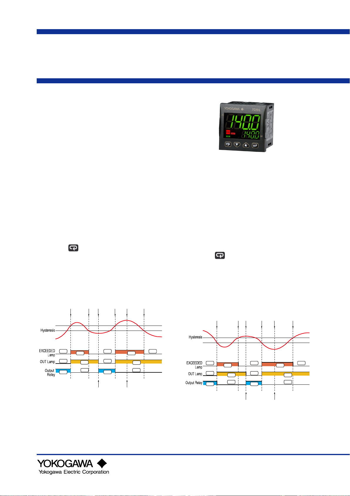
■ Limit Control Function
(High limit control)
When a measured value (PV) exceeds a setpoint
(SP), “EXCEEDED” lamp lights, and “OUT” lamp
turns ON (A). The limit output relay is deenergized
then. “EXCEEDED” lamp turns off when PV goes
into normal condition, while the output (OUT) display
lamp stays on as it is (B). The output (OUT) display
lamp turns off when a confirming operation is done
by an operator (C). The way to confirm is pressing
the RST ( ) key (or by DI1, according to the
setting of setup parameter DIS). The confirming
operation is not accepted during PV exceeds SP (D)
(during EXCEEDED lamp lights*). State of output
relay is de-energized whenever “OUT” lamp is on.
* Check the “HYS” value if the EXCEEDED lamp is not
turn off when PV is lower than SP.
(Low limit control)
When a measured value (PV) exceeds a setpoint
(SP), “EXCEEDED” lamp lights, and “OUT” lamp
turns ON (A).
The limit output relay is deenergized then.
“EXCEEDED” lamp turns off when PV goes into
normal condition, while the output (OUT) display
lamp stays on as it is (B). The output (OUT) display
lamp turns off when a confirming operation is done
by an operator (C). The way to confirm is pressing
the RST ( ) key (or by DI1, according to the
setting of setup parameter DIS). The confirming
operation is not accepted during PV exceeds SP (D)
(during EXCEEDED lamp lights*). State of output
relay is de-energized whenever “OUT” lamp is on.
* Check the “HYS” value if the EXCEEDED lamp is not
turn off when PV is higher than SP.
GS 05C01E81-1
2nd Edition Nov. 201
Page 2

All Rights Reserved. Copyright © 2018, Yokogawa Electric Corporation
GS 05C01E81-11EN
2nd Edition Nov. 2019
TC J
-50 to +1000°C
-58 to +1832°F
TC K
-50 to +1370°C
-58 to +2498°F
TC S
-50 to +1760°C
-58 to +3200°F
TC R
-50 to +1760°C
-58 to +3200°F
TC T
-70 to +400°C
-94 to +752°F
TC N
-50 to +1300°C
-58 to +2372°F
Pt100
-200 to +850°C
-328 to +1562°F
Pt1000
-200 to +850°C
-328 to +1562°F
Linear 0 to 60 mV
Linear 12 to 60 mV
Linear 0 to 20 mA (this selection forces Out 4 = TX)
Linear 4 to 20 mA (this selection forces Out 4 = TX)
Linear 0 to 5 V
Linear 1 to 5 V
Linear 0 to 10 V
Linear 2 to 10 V
■ Hardware Specifications
Display Specifications
Main display: 4 digits height 15.5 mm, 3 color red,
green and amber
Secondary display: 4 digits height 7 mm, green color
Display updating time: 500 ms
Universal Input Specifications
(*)
Sampling time: 130 ms
Resolution: 30000 counts
Total Accuracy: ±0.5% of F.S. ±1 digit
*: ±1.0% of F.S. ±1 digit
Resistance-temperature detector (RTD) measured
current; Pt100: 150 μA, Pt1000: 15.5 μA
Response time: 2 second or less, 63% (10 - 90%)
(The time required for transmission output to reach
63% of the maximum excursion when PV abruptly
changes from 10% to 90%)
Output Specifications
OUT 1: Analog output: 0/4 to 20 mA, galvanically
isolated, RL max. 600Ω ±0.2% of F.S. or 0/2
to 10 V, galvanically isolated, RL min.: 500Ω
±0.3% F.S.
OUT 2: Relay SPST -NO 2A/250 Vac or voltage to
drive SSR 13V max. @1mA, 10.5 min
@15mA ±10%
OUT 3: Relay SPST -NO 2A/250 Vac or voltage to
drive SSR 13V max. @1mA, 10.5 min
@15mA ±10%
OUT 4: programmable: voltage output to drive SSR
13V max. @1mA, 10.5 min. @15mA ±10%,
12 VDC (20 mA) transmitter power supply or
2nd digital input
Regulatory Compliance
CE marking, UL(USA/CANADA)
EMC Directive:
EN 61326-1 Class A, Table 2 (For use in industrial
locations)
EN 55011 Class A, Group 1
(During the test, the instrument continues to
operate at the measurement accuracy within
specification.)
LV Directive:
EN 61010-1, EN 61010-2-030
UL 61010-1 CSA 61010-1
Certified for FM-3810 and FM-3545.
Installation category: II
Pollution category: 2
RoHS Directive:
EN 50581
Power Supply Specification and Isolation Voltage
100 to 240 VAC (-15 to +10% of the nominal value)
Power consumption: 6.0 VA max. (100 to 240 VAC)
Isolation Voltage
3000 V AC for 1 minute between primary and
secondary terminals
(Primary terminals = Power and relay output
terminals, Secondary terminals = Analog I/O signal
terminals, contact input terminals, and
communication terminals.)
Environmental Conditions
Normal Operating Conditions
Operating temperature: 0 to 50°C (32 to 122°F)
Humidity: 20 to 90% RH, not condensing
Temperature Effects
Analog input: It is part of the global accuracy
Reference junction compensation: ±0.1°C/°C or less
Analog output: ±0.05% of F.S./°C or less
Storage temperature
Storage temperature: -20 to +70°C (-4 to +158°F)
Humidity: 20 to 95% RH, not condensing
Page 3

All Rights Reserved. Copyright © 2018, Yokogawa Electric Corporation
GS 05C01E81-11EN
2nd Edition Nov. 2019
■ External Dimensions and Panel
Cutout Dimensions
■ Terminal Arrangement
■ Construction, Mounting, and Wiring
Case: Plastic, self-extinguishing degree: V-0 according
to UL 94
Front protection: IP 65 (when the optional panel gasket
is mounted) for indoor locations according to EN
60070-1
Terminals protection: IP 20 according to EN 60070-1
Installation: Panel mounting
Terminal block: 16 screw terminals for cables of 0.25 to
2.5 mm
diagram, tightening torque 0.5 Nm;
2
(AWG22 to AWG14) with connection
Dimensions: 48 x 48, depth 62 mm
(depth from the panel surface)
(1.89 x 1.89 x 2.87 in.)
Panel cutout: 45[-0, +0.6] x 45[-0, +0.6] mm
(1.78[- 0.000, +0.023] x 1.78[- 0.000, +0.023] in.)
Weight: 180 g max.
Page 4

All Rights Reserved. Copyright © 2018, Yokogawa Electric Corporation
GS 05C01E81-11EN
2nd Edition Nov. 2019
Model Code
Suffix codes
Description
voltage output for SSR.
Type
-L
Always “-L”
Power supply
H
Fixed code
C
analog transmission
Relay output for limit control with PV analog
transmission
N R R
Relay outputs for limit control and alarm
N R N
Relay output for limit control
/ 12VDC 20mA transmitter power supply)
S
RS-485 communication Modbus/RTU
Fixed code
F
Always "F"
Fixed code
/GK
Panel gasket for IP65 (mandatory for FM)
■ Model and Suffix Code
TC10 -L □ C □ □ □ D □ F
A R R
Temperature Controller
with an universal input, one logic input, and one
100 to 240 VAC
Always "C"
Relay outputs for limit control and alarm with PV
OUT1-3
IN/OUT4(Fixed code) D
Serial communication
A R N
N
Selectable I/O (logic input / 12V SSR drive output
None
■ Items to be specified when ordering
Model and suffix code.
■ Standard accessories
Brackets (mounting hardware), Quick Guide
■ Optional accessory
Panel gasket for IP65: A00336
■ User’s Manual
Product user’s manuals can be downloaded or viewed at the following URL.
URL: http://www.yokogawa.com/ns/tc10/im
 Loading...