

Page 1

User’s
Model 735201
Manual
TB200
OPTICAL POWER METER
IM 735201-01E
3rd Edition
Page 2

Foreword
Thank you for purchasing the TB200 Optical Powermeter. This user’s manual
contains useful information about the functions and operating procedures of the
TB200 and lists the handling precautions of the instrument. To ensure correct use,
please read this manual thoroughly before beginning operation. After reading this
manual, keep it in a convenient location for quick reference in the event a
question arises during operation.
Notes
The contents of this manual are subject to change without prior notice as a result
of continuing improvements to the instrument’s performance and functions.
Display contents illustrated in this manual may differ slightly from what actually
appears on your screen.
In this manual, the descriptions are based on Windows 2000.
Every effort has been made in the preparation of this manual to ensure the
accuracy of its contents. However, should you have any questions or find any
errors, please contact your nearest YOKOGAWA dealer as listed on the back
cover of this manual.
Copying or reproducing all or any part of the contents of this manual without the
permission of Yokogawa Electric Corporation is strictly prohibited.
A warranty sheet is included. It cannot be reissued. After reading the sheet,
keep it in a safe location.
Trademarks
Windows is either a trademark or registered trademark of Microsoft Corporation
in the United States and/or other countries.
Adobe, Adobe Acrobat, and PostScript are registered trademarks of Adobe
Systems incorporated.
The company and product names used in this manual are not accompanied by
the trademark or registered trademark symbols (TM and ®).
Other company and product names are trademarks or registered trademarks of
their respective companies.
Revisions
● First Edition July, 2005
● Second Edition September, 2005
● Third Edition November, 2010
3rd Edition : November 2010 (YK)
All Rights Reserved, Copyright © 2005 Yokogawa Electric Corporation
All Rights Reserved, Copyright © 2010 Yokogawa Meters & Instruments Corporation
IM 735201-01E
i
Page 3

Terms and Conditions of the Software License
NOTICE - PLEASE READ CAREFULLY BEFORE USE
Thank you very much for purchasing this medium containing a software program and related documentation provided by
Yokogawa Electric Corporation and Y okogawa Meters & Instruments Corporation (hereinafter called "Y okogawa"), and the
program contained, embedded, inserted or used in the medium (hereinafter called the "Y okogawa Software Program").
By opening this package or plastic wrapping (hereinafter called "Package") enclosing the Yokogawa Sof tware Program, you
acknowledge that you understand and agree to the "T erms and Conditions of the Software License" (hereinafter called "Terms
and Conditions") which is written in the documentation and separately attached. Accordingly, the Terms and Conditions bind you.
The Yokogawa Sof tware Program and its related documentation including ownership of copyright shall remain the exclusive
property of Yokogawa or those third p arties from whom sublicensed software in the Y okogawa Software Program is licensed.
Yokogawa hereby grants you permission to use the Y okogawa Software Program on the conditions that you agree to the T erms
and Conditions before you open the Package and/or install it in or onto a computer.
IF YOU DO NOT AGREE TO THE TERMS AND CONDITIONS, YOU CANNOT OPEN THE P ACKAGE, A ND MUST
IMMEDIATEL Y RETURN IT T O YOKOGAWA OR ITS DESIGNA TED PARTY .
Terms and Conditions of the Soft ware License
Yokogawa Electric Corporation and Y okogawa Meters & Instruments Corporation, Japanese corporations (her einafter called
"Yokogawa"), grant permission to use this Yo kogawa Software Program (hereinafter called the "Licensed Sof tware") to the
Licensee on the conditions that the Licensee agrees to the terms and conditions stipulated in Article 1 hereof.
You, as the Licensee (hereinafter called "Lice nsee"), shall agree to the following terms and conditions for the sof tware license
(hereinafter called the "Agreement") based on the use intended for the Licensed Software.
Please note that Yokogawa grants the Licensee permission to use the Licensed Software under the terms and conditions herein
and in no event shall Yokogawa intend to sell or transfer the Licensed Software to the Licensee.
Licensed Software Name: TB200
Number of License: 1
Article 1 (Scope Covered by these Terms and Conditions)
1.1 The terms and conditions stipulated herein shall be applied to any Licensee who purchases the Licensed Software on the
condition that the Licensee consents to agree to the terms and conditions stipulated herein.
1.2 The "Licensed Software" herein shall mean and include all applicable programs and documentation, without limitation, all
proprietary technology, algorithms, and know -how such as a factor , invariant or process cont ained therein.
Article 2 (Grant of License)
2.1 Yokogawa grants the Licensee, for the purpose of single use, non-exclusive and non-transferable license of the Licensed
Software with the license fee separately agreed upon by both parties.
2.2 The Licensee is, unless otherwise agreed in writing by Yokogawa, not entitled to copy , change, sell, distribute, transfer , or
sublicense the Licensed Software.
2.3 The Licensed Software shall not be copied in whole or in part except for keeping one (1) copy for back-up purposes. The
Licensee shall secure or supervise the copy of the Licensed Software by the Licensee itself with great, strict, and due care.
2.4 In no event shall the Licensee dump, reverse assemble, reverse compile, or reverse engineer the Licensed Software so that
the Licensee may translate the Licensed Software into other programs or change it into a man-readable form from the
source code of the Licensed Software. Unless otherwise separately agreed by Y okogawa, Y okogawa shall not provide the
Licensee the source code for the Licensed Software.
2.5 The Licensed Software and its related documentation shall be the proprietary property or trade secret of Y okogawa or a third
party which grants Y okogawa the rights. In no event shall the Licensee be transferred, leased, sublicensed, or assigned any
rights relating to the Licensed Software.
2.6 Yokogawa may use or add copy protection in or onto the Licensed Software. In no even t shall the Licensee remove or
attempt to remove such copy protection.
2.7 The Licensed Software may include a software program licensed for re-use by a third party (hereinafter called "Third Party
Software", which may include any software program from affiliates of Y okogawa made or coded by themselves.) In the
case that Yokogawa is granted permission to sublicense to third parties by any licen sors (sub-licensor) of the Third Party
Software pursuant to different terms and conditions than those stipulated in this Agreement, the Licensee shall observe such
terms and conditions of which Yokogawa notifies the Licensee in writing separately .
2.8 In no event shall the Licensee modify, remove or delete a copyright notice of Y o kogawa and its licenser contained in the
Licensed Software, including any copy thereof.
ii
Utility
IM 735201-01E
Page 4

Article 3 (Restriction of Specific Use)
3.1 The Licensed Software shall not be intended specifically to be designed, developed, constructed, manufactured, distributed
or maintained for the purpose of the following events:
a. Operation of any aviation, vessel, or support of those operations from the ground;,
b. Operation of nuclear products and/or facilities;,
c. Operation of nuclear weapons and/or chemical weapons and/or biological weapons; or
d. Operation of medical instrumentation directly utilized for humankind or the human body.
3.2 Even if the Licensee uses the Licensed Software for the purposes in the preceding Paragraph 3.1, Yokogawa has no liability
to or responsibility for any demand or damage arising out of the use or operations of the Licensed Software, and the
Licensee agrees, on its own responsibility, to solve and settle the claims and damages and to defend, indemnify or hold
Yokogawa totally harmless, from or against any liabilities, losses, damages and expenses (including fees for recalling the
Products and reasonable attorney’s fees and court costs), or claims arising out of and related to the above-said claims and
damages.
Article 4 (Warranty)
4.1 The Licensee shall agree that the Licensed Software shall be provided to the Licensee on an "as is" basis when delivered. If
defect(s), such as damage to the medium of the Licensed Software, attributable to Yokogawa is found, Yokogawa agrees to
replace, free of charge, any Licensed Software on condition that the defective Licensed Software shall be returned to
Yokogawa’s specified authorized service facility within seven (7) days after opening the Package at the Licensee’s expense.
As the Licensed Software is provided to the Licensee on an "as is" basis when delivered, in no event shall Yokogawa
warrant that any information on or in the Licensed Software, including without limitation, data on computer programs and
program listings, be completely accurate, correct, reliable, or the most updated.
4.2 Notwithstanding the preceding Paragraph 4.1, when third party software is included in the Licensed Software, the warranty
period and terms and conditions that apply shall be those established by the provider of the third party software.
4.3 When Yokogawa decides in its own judgement that it is necessary, Yokogawa may from time to time provide the Licensee
with Revision upgrades and Version upgrades separately specified by Yokogawa (hereinafter called "Updates").
4.4 Notwithstanding the preceding Paragraph 4.3, in no event shall Yokogawa provide Updates where the Licensee or any third
party conducted renovation or improvement of the Licensed Software.
4.5 THE FOREGOING WARRANTIES ARE EXCLUSIVE AND IN LIEU OF ALL OTHER WARRANTIES OF QUALITY AND
PERFORMANCE, WRITTEN, ORAL, OR IMPLIED, AND ALL OTHER WARRANTIES INCLUDING ANY IMPLIED
WARRANTIES OF MERCHANTABILITY OR FITNESS FOR A PARTICULAR PURPOSE ARE HEREBY DISCLAIMED
BY YOKOGAWA AND ALL THIRD PARTIES LICENSING THIRD PARTY SOFTWARE TO YOKOGAWA.
4.6 Correction of nonconformity in the manner and for the period of time provided above shall be the Licensee’s sole and
exclusive remedy for any failure of Yokogawa to comply with its obligations and shall constitute fulfillment of all liabilities of
Yokogawa and any third party licensing the Third Party Software to Yokogawa (including any liability for direct, indirect,
special, incidental or consequential damages) whether in warranty, contract, tort (including negligence but excluding willful
conduct or gross negligence by Yokogawa) or otherwise with respect to or arising out of the use of the Licensed Software.
Article 5 (Infringement)
5.1 If and when any third party should demand injunction, initiate a law suit, or demand compensation for damages against the
Licensee under patent right (including utility
relating to any of the Licensed Software, the Licensee shall notify Yokogawa in writing to that effect without delay.
5.2 In the case of the preceding Paragraph 5.1, the Licensee shall assign to Yokogawa all of the rights to defend the Licensee
and to negotiate with the claiming party. Furthermore, the Licensee shall provide Yokogawa with necessary information or
any other assistance for Yokogawa’s defense and negotiation. If and when such a claim should be attributable to Yokogawa,
subject to the written notice to Yokogawa stated in the preceding Paragraph 5.1, Yokogawa shall defend the Licensee and
negotiate with the claiming party at Yokogawa’s cost and expense and be responsible for the final settlement or judgment
granted to the claiming party in the preceding Paragraph 5.1.
5.3 When any assertion or allegation of the infringement of the third party’s rights defined in Paragraph 5.1 is made, or when at
Yokogawa’s judgment there is possibility of such assertion or allegation, Yokogawa will, at its own discretion, take any of the
following countermeasures at Yokogawa’s cost and expense.
a. To acquire the necessary right from a third party which has lawful ownership of the right so that the Licensee will be able to
continue to use the Licensed Software;
b. To replace the Licensed Software with an alternative one which avoids the infringement; or
c. To remodel the Licensed Software so that the Licensed Software can avoid the infringement of such third party’s right.
5.4 If and when Yokogawa fails to take either of the countermeasures as set forth in the preceding subparagraphs of Paragraph
5.3, Yokogawa shall indemnify the Licensee only by paying back the price amount of the Licensed Software which
Yokogawa has received from the Licensee. THE FOREGOING PARAGRAPHS STATE THE ENTIRE LIABILITY OF
YOKOGAWA AND ANY THIRD PARTY LICENSING THIRD PARTY SOFTWARE TO YOKOGAWA WITH RESPECT
TO INFRINGEMENT OF THE INTELLECTUAL PROPERTY RIGHTS INCLUDING BUT NOT LIMITED TO, PATENT
AND COPYRIGHT.
model right, design patent, and trade mark)
IM 735201-01E
, copy right, and any other rights
iii
Page 5

Article 6 (Liabilities)
6.1 If and when the Licensee should incur any damage relating to or arising out of the Licensed Software or service that
Yokogawa has provided to the Licensee under the conditions herein due to a reason attributable to Yokogawa, Yokogawa
shall take actions in accordance with this Agreement. However, in no event shall Yokogawa be liable or responsible for any
special, incidental, consequential and/or indirect damage, whether in contract, warranty, tort, negligence, strict liability, or
otherwise, including, without limitation, loss of operational profit or revenue, loss of use of the Licensed Software, or any
associated products or equipment, cost of capital, loss or cost of interruption of the Licensee’s business, substitute
equipment, facilities or services, downtime costs, delays, and loss of business information, or claims of customers of
Licensee or other third parties for such or other damages. Even if Yokogawa is liable or responsible for the damages
attributable to Yokogawa and to the extent of this Article 6, Yokogawa’s liability for the Licensee’s damage shall not exceed
the price amount of the Licensed Software or service fee which Yokogawa has received. Please note that Yokogawa shall
be released or discharged from part or all of the liability under this Agreement if the Licensee modifies, remodels, combines
with other software or products, or causes any deviation from the basic specifications or functional specifications, without
Yokogawa’s prior written consent.
6.2 All causes of action against Yokogawa arising out of or relating to this Agreement or the performance or breach hereof shall
expire unless Yokogawa is notified of the claim within one (1) year of its occurrence.
6.3 In no event, regardless of cause, shall Yokogawa assume responsibility for or be liable for penalties or penalty clauses in any
contracts between the Licensee and its customers.
Article 7 (Limit of Export)
Unless otherwise agreed by Yokogawa, the Licensee shall not directly or indirectly export or transfer the Licensed Software to any
countries other than those where Yokogawa permits export in advance.
Article 8 (Term)
This Agreement shall become effective on the date when the Licensee receives the Licensed Software and continues in effect
unless or until terminated as provided herein, or the Licensee ceases using the Licensed Software by itself or with Yokogawa’s
thirty (30) days prior written notice to the Licensee.
Article 9 (Injunction for Use)
During the term of this Agreement, Yokogawa may, at its own discretion, demand injunction against the Licensee in case that
Yokogawa deems that the Licensed Software is used improperly or under severer environments other than those where
Yokogawa has first approved, or any other condition which Yokogawa may not permit.
Article 10 (Termination)
Yokogawa, at its sole discretion, may terminate this Agreement without any notice or reminder to the Licensee if the Licensee
violates or fails to perform this Agreement. However, Articles 5, 6, and 11 shall survive even after the termination.
Article 11 (Jurisdiction)
Any dispute, controversies, or differences between the parties hereto as to interpretation or execution of this Agreement shall be
resolved amicably through negotiation between the parties upon the basis of mutual trust. Should the parties fail to agree within
ninety (90) days after notice from one of the parties to the other, both parties hereby irrevocably submit to the exclusive jurisdiction
of the Tokyo District Court (main office) in
Article 12 (Governing Law)
This Agreement shall be governed by and construed in accordance with the laws of Japan. The Licensee expressly agrees to
waive absolutely and irrevocably and to the fullest extent permissible under applicable law any rights against the laws of Japan
which it may have pursuant to the Licensee’s local law.
Article 13 (Severability)
In the event that any provision hereof is declared or found to be illegal by any court or tribunal of competent jurisdiction, such
provision shall be null and void with respect to the jurisdiction of that court or tribunal and all the remaining provisions hereof shall
remain in full force and effect.
Japan for settlement of
the dispute.
iv
IM 735201-01E
Page 6
Checking the Contents of the Package
After opening the package, check the following items before beginning use. If
any of the contents are incorrect, missing, or appear to be abnormal, please
contact your Yokogaw a dealer or representa tive.
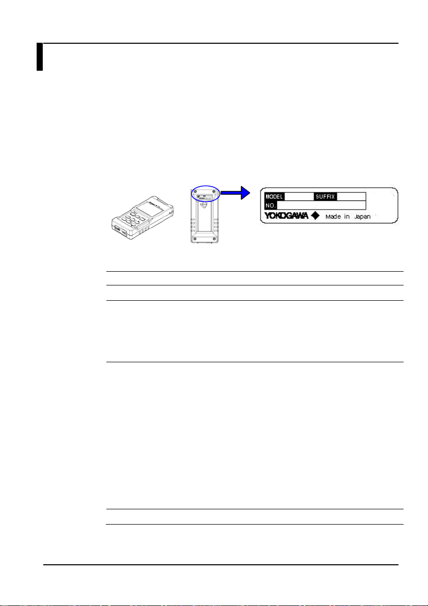
TB200 Main Unit
Check that the model and suffix code on the name plate on the rear of the
instrument match those of your order. Please have the instrument number
(NO.) ready when contacting your deal er or re presenta tive.
TB200 main unit
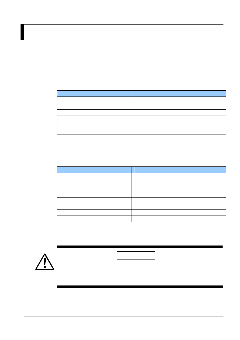
Models and Suffix Codes
Model Suffix Code Description
735201
Power cord - M
With/without sensor
head
Options /PR Protector (with stand)
Main unit
rear panel
AC adapter PSE Conforming (2 pin)
- C
- F
- G
- J
- CA0
- CA1
- CA3
AC adapter UL/CSA compliant (UL2P)
AC adapter VDE compliant (CEE-C2)
AC adapter AS compliant (AS2P)
AC adapter BS compliant (BS2P) angle
Without sensor head (when ordering main
unit only)
With sensor head (405 nm, 1 wavelength
calibration)
Inaccuracy under standard conditions:
±2.5%
With sensor head (405/660/785 nm, 3
wavelength calibration), inaccuracy under
standard conditions
405 nm:±2.5%
660 nm:±3.0%
785 nm:±3.0%
Name plate
IM 735201-01E
v
Page 7
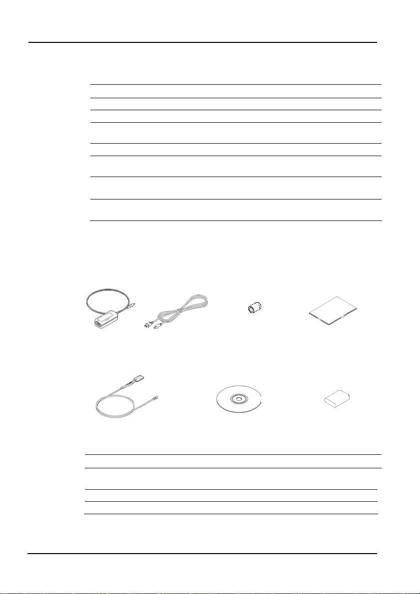
Standard Accessories
The following accessories come standard.
Product Name Model Qty. Note
AC adapter SU2007A 1
Power cord - 1
UM connector
protective cap
User's manual IM735201-01E 1 This manual
Sensor head 735201 1
Software
(TB200 Utility)
Sensor protective
cap
Note) The model when purchasing the sensor head by itself is 735221.
Sensor head
(when purchased together
Options (Sold Separately)
The following options are available for purchase separately.
Name Model Notes
Sensor head 735221
Protector SU2002A Protector with stand
Soft carrying case SU2006A
1 Attached to TB200 main unit
When purchasing together with
the TB200
-
-
Power cordAC adapter
UM connector protective cap
(on the TB200 main unit)
Software
(TB200 Utility)
Available on the sensor head
1
accessory CD.
1 Attached to the sensor head
User’s manual
(this document)
Sensor protective cap
(on sensor head)
Model when ordering only the
sensor head
vi
IM 735201-01E
Page 8

Safety Precautions
To ensure safe and correct operation of the instrument, you must take the safety
precautions given below. The instrument’s protective functions may not work if
used in a manner not described in this manual. Yokogawa bears no responsibility
for, nor implies any warranty against damages occurring as a result of failure to
take these precautions.
The following safety symbols and wording is used in this manual.
Warning: Handle with care. Refer to the user’s manual or service
manual. This symbol appears on dangerous locations on the
instrument which require special instructions for proper handling
or use. The same symbol appears in the corresponding place in
the manual to identify those instructions.
Direct current
Alternating current
IM 735201-01E
vii
Page 9

The following precautions must be taken to prevent potentially fatal accidents.
Use the Correct Power Supply
Check that the supply voltage of the instrument m atches that of the p ower
supply to be used before turning the power ON.
Use the Correct AC Power Cord and Adapter
To prevent electric shock or fire when using the AC adapter, only use the
dedicated AC adapter and pow er cord supplied with the instrument.
Also do not use the power cord and AC adapter that came with the
instrument on any other device.
Do Not Use Near Flammable Gases
Never use the instrument in locations with flammable or explosive gases or
vapors. Doing so is extremely dangerous.
Do Not Remove the Case
Only qualified Yo kogawa te chnicians may remove the case.
Handle the Item under Test Properly
The instrument measures devices that emit lasers. To prevent exposure
to radiation from lasers, operate the item under test strictly according to the
device’s user’s manual. Also, take care when handling the lens and other
optical devices as doing so can cause damage to the eye.
To prevent fire or electric shock, do not insert or drop metallic objects into the
opening.
When connecting to commercial power, conn ect directly to a ded icated outlet.
Do not use extension cords as they can overheat and cause fires.
Do Not Place the Power Cord on or Near Heaters
Heat can degrade the insulating coating resulting in fires or electric shock.
Do Not Damage or Modify the Pow er Cord
=> Fire or electric shock can result.
Do Not Use Extension Co rds or Splitte rs
=> Cables can overheat, causing fires.
Do Not Bend, Twist, or Forcibly Pu ll the Cable
=> Fire or electric shock can result.
Do Not Plug or Unplug the Power Cord with Wet Hands
=> Electric shock can result.
Insert the Power Plug Completely and Securely into the Outlet
=> If metal or other objects are allowed to contact the power supply plug,
fire or electric shock can result.
WARNIN G
viii
IM 735201-01E
Page 10

Safety Precautions
Do not remove the case. The instrument's internal components carry high
voltages and are extremely dangerous.
For internal inspection or adjustment, contact your nearest YOKOGAWA
dealer.
If there are any symptoms of trouble such as strange smells or smoke coming
from the instrument, turn the power OFF immediately, and remove the battery
pack or the power cord from the outlet. If such an irregularit y occurs, co ntact
your YOKOGAW A dealer .
Nothing should be placed on the power cord. The cord should be kept away from
any heat sources. When unplugging the pow er cord from the outlet, neve r pull
by the cord itself. Always hold and pull by the plug. If the power cord is
damaged, contact your dealer for re placement.
Always unplug the power cord from the outlet, and check that all externally
connected wires and cables are removed before moving the instrument.
=> Otherwise, the cords can become damaged, causing fire or electric
shock.
Be sure to unplug the power co rd from the outlet during lightning storms.
=> Fire, electric shock, or malfunction can result.
Do not use old and new batteries at the same time.
=> Explosion or leakage of the batteries can result, caus ing fire, injury, or
contamination of the surrounding area.
Check the polarity of the batteries (plus/minus orientation) before installing them.
=> Incorrect orientation can result in explos ion or leakage of the batteries,
causing fire, injury, or contamination of the surrounding area.
If the instrument experiences an abnormality, do not attempt to repair the
instrument your self.
=> Electric shock or damage can result. Also, any repairs conducted without
authorized consent will not be covered by the product warranty.
Never disassemble or rework the instrument.
=> Fire, electric shock, or malfunction can result.
When handling parts that open and close, such as when changing the battery,
take care not to pinch or injure your finger.
See below for operating environment limitations.
This product is a Class A (for industrial envir onments) produ ct. Operat ion of
this product in a residential area may cause radio interference in which case
the user will be required to corre ct the interference .
CAUTION
IM 735201-01E
ix
Page 11

General Handling Precautions
Take care not to damage the instrument by dropping it.
Unplug During Periods of Extended Non-Use
Unplug the power cord from the outlet. Remove the dry cells. Failure to
remove the battery pack during long periods of non-use can cause the
battery fluid to leak into the instrument, causing damage.
Do not place any other instrument or anything containing liquid on top of the
instrument. Doing so can lead to malfunction.
Since the LCD screen is very vulnerable and can be easily scratched, do not
allow any sharp objects near it. Also never expose it to vibrations and shocks.
Do Not Install the Instrument in Any of the Following Places
・ Humid or dusty areas
・ On an unstable surface
・ In direct sunlight or in locations such as automobiles where the
temperature can become high
・ In a location where it may become vibrated or shocked
・ Near sources of heat such as heating appliances
The IEC61010-1 pollution degree and overvoltage category of the instrument are
as follows.
・ Pollution degree 2
Pollution degree refers to the degree of adherence by a solid, liquid, or
vapor that reduces the withstand voltage or surface resistance factor. It
is a number that expresses the degree to which an instrument or one
of its components may become poluted while being used.
Pollution degree 2 applies to normal indoor atmospheres. It
applies only to normal or non-conductive pollution, but
conductivity may occur temporarily depending on
concentrations.
・ Overvoltage category II
Overvoltage category (installation category) is a number that defines
excessive voltage, and includes regulations for impulse withstand
voltage.
Overvoltage category II applies to electrical equipment that is powered
by a fixed installation such as a distribution board.
● ● Read this section before using the instrument for the first time.
If this instrument is used in a manner not specified in this manual, the
protective features provided by the instrument may be impaired.
CAUTION
x
IM 735201-01E
Page 12

Safety Markings
Safety Markings
The following markings are used in this manual.
WARNING
CAUTION
Note Calls attention to information that is important for proper
Bolded Characters
Bold characters and symbols used in the Procedure sections indicate the text
and symbols on the keys of the instrument.
Items set in boldface mainly refer to controls on the instrument and other devices,
or on-screen interface elements such as menu commands with which the user
interacts.
Improper handling or use can lead to injury to the user or
damage to the instrument. This symbol appears on the
instrument to indicate that the user must refer to the user's
manual for special instructions. The same symbol
appears in the corresponding place in the user's manual to
identify those instructions. In the manual, the symbol is
used in conjunction with the word “WARNING” or
“CAUTION.”
Calls attention to actions or conditions that could cause
serious or fatal injury to the user, and precautions that can
be taken to prevent such occurrences.
Calls attentions to actions or conditions that could cause
light injury to the user or damage to the instrument or user's
data, and precautions that can be taken to prevent such
occurrences.
operation of the instrument.
IM 735201-01E
xi
Page 13

Contents
Foreword ......................................................................................................i
Terms and Conditions of the Software License .........................................ii
Checking the Contents of the Package......................................................v
Safety Precautions ....................................................................................vii
Safety Markings..........................................................................................xi
Chapter 1 Explanation of Functions
1.1 Names and Functions of Parts ..............................................1-1
1.2 List of Functions...................................................................... 1-6
Chapter 2 Preparing for Measurement
2.1 Handling Precautions............................................................. 2-1
2.2 Connection Procedure ...........................................................2-3
2.3 Turning the Power Supply ON and OFF............................... 2-5
Chapter 3 Measurement
3.1 Entering Measurement Conditions........................................ 3-1
3.1.1 Setting the Wavelength ....................................................3-2
3.1.2 Setting the NA (Numerical Aperture) Correction Coefficient
........................................................................................... 3-3
3.1.3 Entering Averaging Settings............................................. 3-5
3.2 Modes ..................................................................................... 3-6
3.2.1 List of Modes..................................................................... 3-6
3.2.2 Diagram of Relationship between Modes .......................3-6
3.3 Absolute Value Measurement................................................ 3-7
3.3.1 Measuring Optical Power .................................................3-7
3.3.2 Changing Units .................................................................3-7
3.3.3 Fixing the Measuring Range (Range Hold)..................... 3-8
3.3.4 Displaying Maximum Values (MAX Hold)........................3-9
3.3.5 Measuring after Setting the CAL Value.......................... 3-10
3.4 Relative Value Measurement............................................... 3-12
xii
IM 735201-01E
Page 14

Chapter 4 Measuring Using USB (Remote Control)
4.1 USB Communication Function...............................................4-1
4.2 Installing USB Drivers .............................................................4-2
4.3 List of Commands...................................................................4-4
4.4 Sample Program.....................................................................4-9
4.4.1 Installing the DLL...............................................................4-9
4.4.2 Sample Software...............................................................4-9
Chapter 5 Notes When Purchasing the Sensor Head by
Itself
5.1 Uploading Sensor Specific Data.............................................5-1
5.2 Displaying the Sensor Head Serial Number..........................5-3
Chapter 6 Maintenance
6.1 Error Messages.......................................................................6-1
6.2 Troubleshooting ......................................................................6-3
6.3 Periodic Calibration.................................................................6-4
Chapter 7 Specifications
7.1 Specifications ..........................................................................7-1
7.2 External Dimensions...............................................................7-5
Appendix
Appendix 1 Table of NA Correction Coefficients.......................... App-1
Appendix 2 Table of 7-Segment Display Characters ..................App-4
IM 735201-01E
xiii
Page 15
Chapter 1 Explanation of Functions
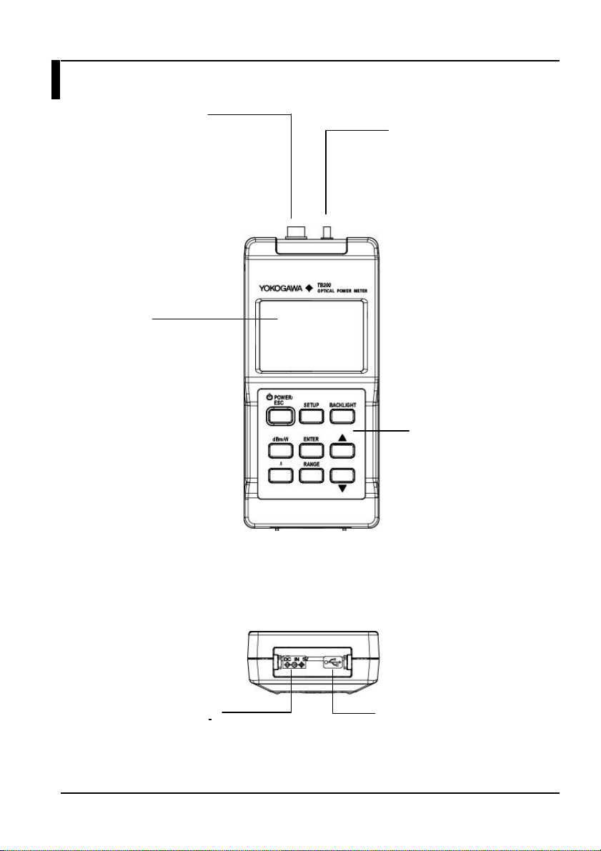
1.1 Names and Functions of Parts
Sensor Connector
IM 735201-01E
Connects to the
sensor head.
⇒See p. 2-4
Display
Displays measured
results and various
settings.
=> See p.1-4 and
p.1-5
AC Adapter Terminal
For connecting the AC
Keys
adapter.
Analog Out Terminal
(UM Connector)
Outputs a voltage
according to the
sensor head output.
=> See p. 1-7 and
1-8
Keys
Nine keys for
operating the
instrument.
=> See p.1-2 and
p.1-3
USB Terminal
For connecting the USB
cable.
1-1
Page 16
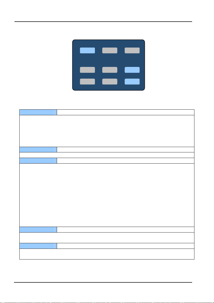
1.1 Names and Functions of Parts
Keys
POWER/ESC SETUP
POWER/ESC SETUP
dBm/W
dBm/W
λ
λ
ENTER
ENTER
RANGE
RANGE
POWER/ESC
Power supply and escape key
This key turns the power ON and OFF. Press the key to start the instrument with the power
save function set. If you hold down the button until the power save indicator “PWR SAVE”
disappears, the instrument starts with the power save function disabled. To turn the
instrument OFF, hold down the key until the LCD display goes out.
You can press the key once during operation to return to normal measurement mode (ESC
function).
BACKLIGHT
Backlight key
Press this key to turn ON the backlight. Press again to turn it OFF.
dBm/W
Unit selection key
This key switches the units for absolute value measurement mode (dBm or W). Each time
you press the key, the selected units change as follows:
dBm display => W display (switches automatically between mW, µW, and nW) => mW
display (fixed) => dBm display
Also, if you hold down the ENTER key while pressing this key, the instrument enters relative
value measurement mode. The measured value at the moment the key is pressed is set as
the reference value for relative value measurement. The instrument enters relative value
measurement mode (and displays the difference in the measured value from the reference
value) from the next measurement thereafter. Every time the key is pressed, the reference
value is updated. In relative value measurement mode, this key switches to absolute value
measurement mode.
(Related keys: ENTER)
λ
Wavelength key
Press this key to enter a mode for entering wavelength settings. Change values using the
UP and DOWN keys, then press the ENTER key to enter the selection.
RANGE
Range hold key
Press this key to fix the measuring range. Press it again to release the range. Press the
UP and DOWN keys to change the range.
BACKLIGHT
BACKLIGHT
▲
▲
▼
▼
1-2
IM 735201-01E
Page 17

1.1 Names and Functions of Parts
SETUP
Press this key to change to the Setup mode, in which various settings can be entered.
In absolute value measurement mode, measurement conditions can be entered in the
following order:
Averaging setting, max hold setting, NA correction coefficient setting, sensor serial number
display.
(Related keys: UP/DOWN, ENTER)
ENTER
Enters various kinds of selectable settings.
(Related keys: UP/DOWN, SETUP, dBm/W)
▲, ▼ Selection keys (UP/DOWN)
Use these keys to turn items ON and OFF, and to enter values.
Press once to change the selection UP or DOWN. Hold down to quickly scroll UP or DOWN
through the selections.
(Related keys: SETUP, ENTER)
Setup mode key
Entry key
IM 735201-01E
1-3
Page 18
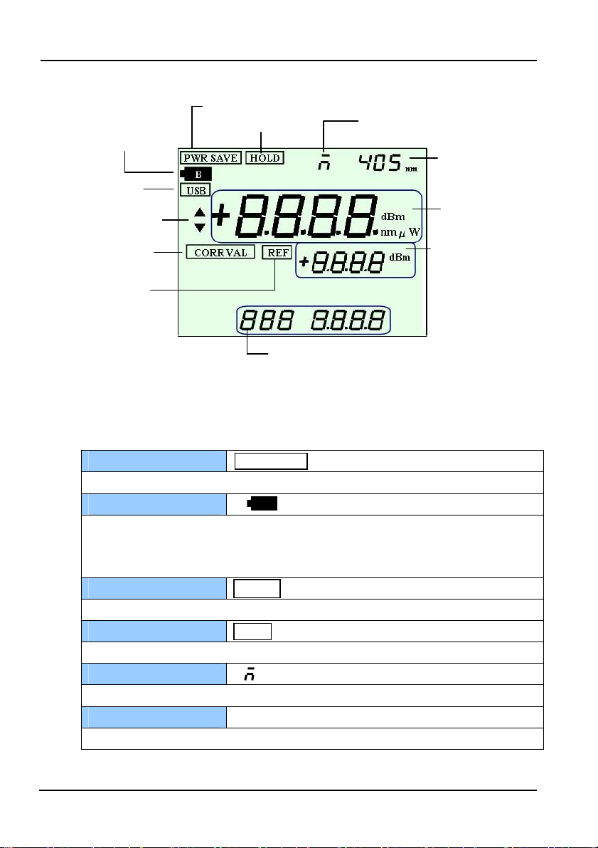
1.1 Names and Functions of Parts
r
e
play
Screens
Battery alarm
USB
communication
Arrow key indicator
User calibration
Relative value
measurement
Power save
“PWR SAVE” is displayed when the power save function is set.
Battery alarm
The indicator above blinks when the remaining battery charge is too low to provide
sufficient power for operation. Change the batteries or connect the AC adaptor. During
alarms, resuming is disabled.
Range fixing
The “HOLD” indicator is displayed when range switching is held.
USB communication
The “USB” indicator is displayed when in USB mode.
MAX hold
The mark above is displayed when the MAX hold function is set.
Wavelength setting
Displays the set wavelength (nm).
Power save
Range hold
PWR SAVE
HOLD
USB
“405 nm”
MAX hold
Measured
wavelength
Measured value
dis
Set value display
Rel. val. meas. ref. val.
Fixed range
NA correction value
MAX hold value
CAL valu
Setup mode display
Averaging ON/OFF
NA correction ON/OFF
Sensor serial numbe
BB
1-4
IM 735201-01E
Page 19

1.1 Names and Functions of Parts
Arrow key indicators “▲” “▼”
Displayed when various kinds of selectable settings are available.
Measured value display
Displays the measured value and its units. Messages appearing during errors and entry
of settings are also displayed here. (Related keys: dBm/W)
Correction value setting
The “CORR VAL” indicator is displayed when the correction value has been set using
the user calibration function.
Relative value
measurement
The “REF” indicator is displayed when in relative value measurement mode.
Setting value display
The reference value is displayed when in relative value measurement mode.
Also displays setting values and selection messages.
Setup mode display
Displays NA correction ON/OFF and the sensor serial number.
“+8.8.8.8.dBm nmµW”
CORR VAL
REF
“8.8.8.8”
“8 8 8 8.8.8.8”
IM 735201-01E
1-5
Page 20

1.2 List of Functions
Function Overview/Description
Optical power level
measurement
Range setting Sets the range automatically according to the level of received
Auto zero set Automatically sets zero when the power is turned ON.
Wavelength sensitivity
correction
Relative value
measurement
Absolute value
measurement
unit switching
Averaging Averages measured values internally and displays them.
Max hold Displays the maximum value during measurement.
NA (aperature)
correction
Sensor head
S/N display
User calibration Adds setting values displayed in normal measurement mode
Backlight Turning the backlight ON allows you to see the display in the
Displays the optical power level of the light received by the
sensor head in the display.
light. You can specify a fixed range. The setting range is -30 dBm
to +20 dBm
The user need not set zero manually.
The wavelength sensitivity can be corrected in the range from
400 to 850 nm (in 1 nm steps). Accurate measurements can be
obtained by matching with the wavelength of the light source
being measured.
You can set a reference value and display the change in level
relative to the reference value (units: dB).
You can switch the displayed units between dBm and W.
When W is selected, mW, uW, or nW is automatically selected
and displayed according to the optical power.
You can also fix the displayed units at mW.
The number of measured data values averaged is fixed at 20.
A moving average is taken every measurement interval.1
When measuring at high NA, you can correct error due to
angular incidence characteristics of the sensor. The setting range
is 0.500 to 2,000 (in 0.001 steps). However, the correction value
must be selected from the NA correction coefficient table in
appendix 1.
Displays the serial number of the sensor head connected to the
instrument.
and displays them. The available setting range is -10 dB to +10
dB.
dark.
1-6
IM 735201-01E
Page 21
1.2 List of Functions
A
a
Power save
(only when using a
battery)
Battery alarm
(only when using a
battery)
Resume
Analog output3 Outputs an analog voltage for each range according to the
USB communication Lets you edit settings and acquire measured values via USB
2
The settings that were active when the power was turned OFF
When running on dry cells, the power turns OFF automatically if
a key is not pressed within ten minutes.
The battery indicator blinks when the battery runs low.
are saved and restored the next time the power is turned ON (if
shutdown successfully).
The function is disabled when the battery alarm indicator is
displayed. In this case, the instrument saves the settings that
were last active when the power was turned OFF normally.
measured value.
(keys cannot be used for control when using this function).
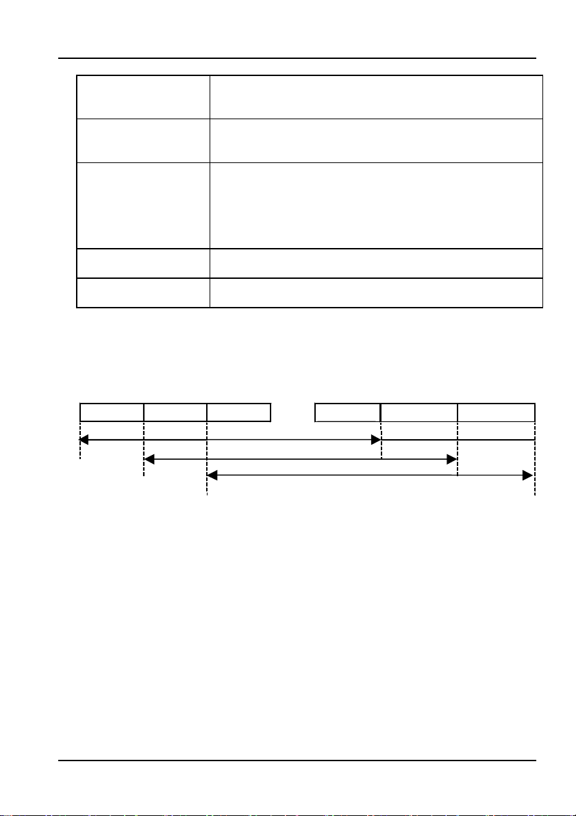
1. Moving average
Averages measured values from a determined number of measurements.
The average value is updated at all times as the most recent values are
loaded and the oldest ones are discarded.
Meas val 1 Meas val 2 Meas val 3
vg. over this are
Next, avg. over this area
Meas val N Meas val N+1
・・・
Then this area, and so on
Meas val N+2
N : No. of measurements (for this instrument, N =20)
2. The settings that are saved by the Resume function are as follows.
● Absolute value/relative value setting mode ● Range AUTO/HOLD
● Relative measurement value ● Range info. (only with range hold)
● Measurement wavelength ● NA correction value ON/OFF
● Last set detail wavelength ● Last set NA correction value
● Displayed units ● CAL setting ON/OFF
● Averaging ON/OFF ● Last set CAL value
● Turning MAX Hold ON/OFF
IM 735201-01E
1-7
Page 22

1.2 List of Functions
e
p
e
3. Analog Out
You can convert measured results to voltages of 0–2 V and output them. Output
values can be input to another device such as a recorder for comparison and trend
analysis. At each measuring range, the output value is the voltage from 0 to 2 V
that is proportional to the input value. With a fixed range, the output value is under
range at approximately 0.1 V and over range at approximately 2 V. When an
overrange occurs, a voltage of 2 V or over can be output from the analog out
terminal. Since with auto-switching the measuring range changes from
approximately 0.1 V to approximately 2 V, the output values are non-continuous.
(V)
2
ut valu
1
0.1
0
(V) Out
2
1
Output valu
0.1
0
-20 -10 103-40 0
-30 20 30
Input power (dBm)
Analog out when using automatic ranging
-20 -10 10-40 0
-30 20 30
Input power (dBm)
Analog out when using fixed measuring range (-20 dB)
1-8
IM 735201-01E
Page 23

Chapter 2 Preparing for Measurement
2.1 Handling Precautions
The following describes precautions that must be taken during use of the instrument.
This instrument utilizes ultra-precision optical components. In order for performance to
be guaranteed, please take note of the following.
Precautions during Use
1) Do not drop or expose the instrument to excessive physical shock. The
instrument is protected with plastic casing, but contains fragile optical
components.
2) Do not place the instrument in direct sunlight, or in high-temperature or highly
humid locations such as inside of a car for long periods of time.
3) Do not bring the instrument close to strong electromagnetic waves. Doing so
can lead to malfunction.
4) Do not use the instrument and mobile phones simultaneously in the same
vicinity.
5) The instrument is portable and can be used outdoors under battery power, but
is not waterproof. Never operate the instrument in the rain.
6) Do not disassemble the device.
7) Do not peer into the ends of the optical fiber, the beams as they travel through
the air, the optical connector, or other parts connected to the light source.
Doing so can result in injury to the eyes from lasers. Take appropriate caution
when handling.
8) Incidence of excessive or highly concentrated light outside of the optical power
measuring range can damage the sensor element.
9) When the optical power is expressed as an average the value appears low,
but the instantaneous power can be quite high. Take extra precaution with low
duty, high-cusp pulses.
10) If the surface of the sensor is soiled with dirt or grime, clean the end with
specialized optical connector cleaner or a dust-resistant cloth.
11) If any plastic parts become soiled, wipe with a soft and dry cloth.
12) When not using the instrument, attach the cap to protect the sensor from dirt,
grime, and other foreign particles.
13) To prevent damage when attaching or removing the optical input connector
cap, take care not to rub the connector against the cap.
14) Never insert or remove the sensor head while the power is ON.
15) Do not connect anything to the connectors (sensor head, analog out terminal,
etc.) other than the specified product. Damage can result.
16) The sensor head contains optical components that are easily scratched.
Take care not to scratch or crack any part of the sensor head.
17) Only turn ON the power if the sensor head is attached.
IM 735201-01E
2-1
Page 24

2.1 Handling Precautions
Precautions When Using the Batteries
1) If the plus or minus terminal of the battery holder is dirty, contact with the
battery will be weakened, possibly causing the power to cut out. If dirty, wipe
the plus and minus terminals clean with a dry cloth.
2) Do not allow the batteries to come into contact with water (including rain water
and sea water). Also, do not apply strong physical shocks.
3) Shorting the plus and minus terminals of the batteries with metal or other
conductive objects causes a large current to flow that can damage the
batteries and emit heat. Take care not to short the terminals when handling
the batteries.
4) Disassembling the batteries or placing them in fire is extremely dangerous and
must never be attempted.
5) Do not discard spent batteries together with general household waste (unless
your local laws permit doing so).
6) Check the polarity/orientation of the batteries carefully before inserting them
into the battery holder. Incorrectly oriented batteries can result in damage to
the instrument.
7) Remove the batteries during periods of extended non-use. Leakage from
batteries can occur, resulting in damage to the instrument.
8) Always operate the instrument in a way that is appropriate for the type of
batteries you are using.
Cautions When Using the AC Adapter
Use the AC adapter that came with the instrument, and the country-specific
power cable that was packaged together with the AC adapter. Connect a power
supply that meets the specifications of the AC adapter.
To use the cable and adapter, insert the power cable firmly into the inlet on the
AC adapter, and connect the output cable firmly to the AC adapter terminal on
the instrument. Also, only use these items indoors. Use them in the same
temperature range as is required for the instrument. Note that the safety standard
for the AC adapter specifies an operational temperature of 0–40°C. Never use an
AC adapter or power cable other than the dedicated ones available for use with
this instrument, as damage can result.
Precautions When Using the CD
This CD contains software, and is for use in a computer only. Do not play this on
an audio CD player as the high volume may damage your hearing or audio
speakers.
Precautions When Discarding the Instrument
Treat the instrument as general industrial waste, separate from household waste,
and dispose of the instrument according to relevant local laws.
2-2
IM 735201-01E
Page 25

2.2 Connection Procedure
Connecting the AC Adapter
Connect the AC adapter output terminal to the instrument’s AC adapter terminal
after opening the cap.
Figure 2-1 AC Adaptor Output Terminal
Installing the Batteries
When using batteries,
turn the screw on the rear
panel with a coin or other flat
object to remove the cover,
then install the batteries.
Turning the screw
locks/unlocks the cover as
shown in the figure.
Insert two AA batteries into
the holder following the
polarity markings. Always close the
cover after installing batteries.
If the low battery indicator blinks, you
must change the batteries
immediately. The instrument runs for
approximately twenty-four hours
when using alkaline AA batteries
(performance may vary depending
on the operating conditions).
-
+
+
-
Lock Unlock
Figure. 2-2 Installing the batteries
IM 735201-01E
2-3
Page 26

2.2 Connection Procedure
Connecting the Sensor Head
Connect the sensor head connector to the sensor
connector terminal on the instrument. Align the connector
tab with the groove, then push in. The connector head
cannot be connected if the tab is not properly aligned.
Figure 2-3 Sensor head connection diagram
● ● To remove the sensor head, hold and pull by the connector
Do not pull by the cable itself as it can break.
CAUTION
2-4
IM 735201-01E
Page 27

2.3 Turning the Power Supply ON and OFF
When Using the AC Adapter
When the power is OFF, press POWER/ESC key.
The instrument starts up in normal measurement mode.
Figure 2-4 Example of the normal measurement mode screen
Never use an AC adapter or power cable other than the dedicated
ones available for use with this instrument, as damage can result.
When Using Batteries
When the power is OFF, press POWER/ESC.
The instrument starts up in normal measurement mode.
“PWR SAVE” is displayed in the upper left part of the screen.
Figure 2-5 Display example in power save mode
Note
To start up with the power save function OFF, make sure the power is
・
turned OFF, then hold down the POWER/ESC key until the “PWR
SAVE” display goes out.
This instrument features a zero adjust function (zero point adjustment)
・
that automatically removes the offset within the circuits. Thus, no zero
adjustment by the user is necessary
WARNING
Indicates that the power save function is
operating. The power turns OFF if no key is
pressed for ten minutes.
IM 735201-01E
2-5
Page 28
2.3 Turning the Power Supply ON and OFF
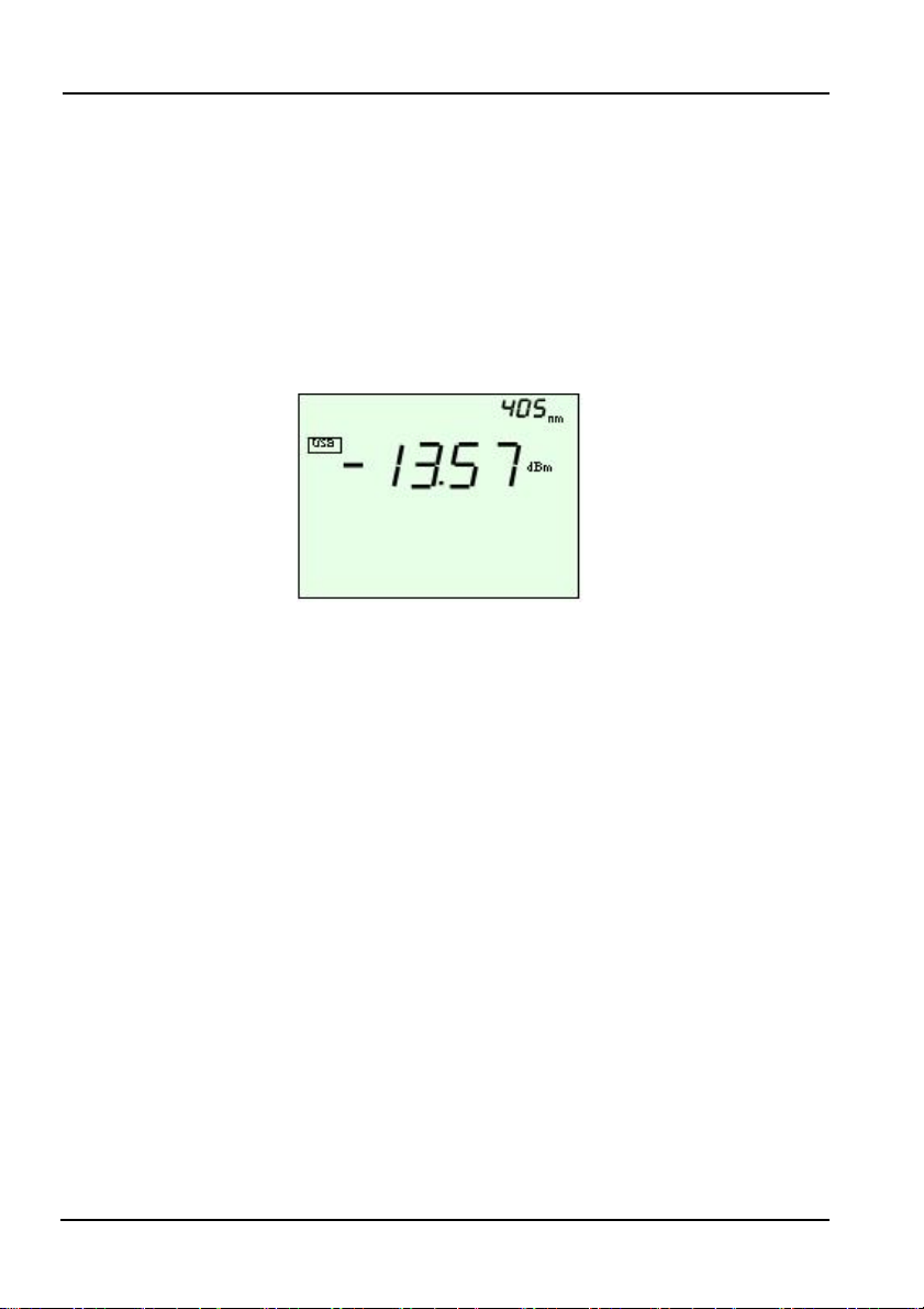
Starting Up in USB Mode
When the instrument is connected to a PC with a USB cable, the instrument
enters USB mode when the power is turned ON. It also enters this mode if the
cable is connected after the power is turned ON. Therefore, if a USB cable is
connected while the instrument is in normal measurement mode, it switches to
USB mode automatically. In USB mode, all keys are disabled except for the
POWER and BACKLIGHT keys.
The “USB” indicator is displayed when the instrument starts up in USB mode or
switches to that.
Figure 2-6 Display example in USB mode
Turning the Power OFF
1. Hold down the power key until the LCD display goes out.
2. Attach the sensor head protective cap.
3. When using the AC adapter, turn the instrument OFF with the power key
before disconnecting the adapter.
2-6
IM 735201-01E
Page 29

Chapter 3 Measurement
P
3.1 Entering Measurement Conditions
The following three measurement condition parameters can be set.
1) Wavelength setting (typical value, or switching of the wavelength in 1 nm
steps)
2) NA setting
3) Averaging setting
The conditions set here are stored until the next time you enter settings, even if
the power is turned OFF (Resume function.See p.1-7).
If you make a mistake, you can press the ESC or SETUP key.
ESC key: Return to normal measurement mode.
The setting procedures described all start from the initial screen in normal
measurement mode.
The initial screen in normal measurement mode.
Figure 3-1 Example of the initial screen in normal measurement mode.
key: Cancel setting and advance to the next setting.
SETU
Same screen as when first starting up.
Confirm that the screen shows the initial
settings, then begin the procedure for entering
measurement conditions.
IM 735201-01E
3-1
Page 30

3.1 Entering Measurement Conditions
3.1.1 Setting the Wavelength
You can set the correction wavelength for the sensor head to match the used
wavelength. The sensor element has wavelength sensitivity characteristics. To obtain
accurate measurements, the instrument is set to a wavelength that matches the
wavelength of the measured light.
Choosing a Typical Wavelength
1. Perform the operation from the initial screen in normal measurement mode
(Figure 3-1).
2. Press the λ key. The wavelength setting screen appears.。
Figure 3-2 Wavelength setting screen
3. Each time you press the UP key, the displayed wavelength cycles through
the following options: “405”, “660”, “785”, “Prev Val”, “Usr”, “405”, and so on.
Pressing the DOWN key cycles in the reverse order.
(Note: Previous value refers to the wavelength most recently set.)
4. After selecting a wavelength, press the ENTER key. The typical wavelength
setting is finalized.
Setting to an Arbitrary Wavelength. (Can Be Set in Units of 1 nm).
5. After setting the wavelength display to “USr”, press the ENTER key.
The detail wavelength setting screen appears.
Figure 3-3 Detail wavelength setting screen
6. Press the UP or DOWN key. Change the wavelength in units of 1 nm.
The available setting range is 400 to 850 nm.
7. Press the ENTER key. The detail wavelength settings are finalized.
3-2
IM 735201-01E
Page 31

3.1 Entering Measurement Conditions
3.1.2 Setting the NA (Numerical Aperture) Correction Coefficient
You can set the NA correction coefficient and correct the angle dependency of
the light accepted by the sensor head resulting from the aperture.
1. Perform the operation from the initial screen in normal measurement mode
(Figure 3-1).
2. Press the SETUP key. The setup mode screen appears.
3. Press the SETUP key two more times. The NA correction coefficient setting
ON/OFF screen appears.
Figure 3-4 Display example of the NA correction coefficient setting
ON/OFF screen
4. Each time you press the UP or DOWN key, “ON” or “OFF” blinks.
Select “ON”.
5. Press the ENTER key. The NA correction coefficient blinks.
Figure 3-5 Example of a display while setting the NA correction
coefficient
6. Press the UP or DOWN key to change the value. Determine the value from
the NA correction coefficient table (see appendix 1).
7. Press the ENTER key. The sensor serial number reference screen appears
(see Figure 5-1). The NA correction coefficient setting is finalized.
IM 735201-01E
3-3
Page 32

3.1 Entering Measurement Conditions
8. Press the ENTER key. The instrument returns to the normal measurement
mode screen.
Figure 3-6 Example of the display in normal measurement mode when
the NA correction coefficient setting is enabled.
Note
The NA correction coefficient differs depending on the NA and RIM of
・
the light source you are using.
Select a coefficient from the NA correction coefficient table in appendix
・
1 according to the conditions matching the light source.
NA
Stands for numerical aperture, and is a number that determines the
light-condensing characteristics of a lens.
The larger the NA, the more the beam is concentrated, allowing higher-density
recording.
3-4
IM 735201-01E
Page 33

3.1.3 Entering Averaging Settings
1. Perform the operation from the initial screen in normal measurement mode
(Figure 3-1).
2. Press the SETUP key. The averaging setting screen appears.
Figure 3-7 The averaging setting screen
3. Each time you press the UP or DOWN key, “ON” or “OFF” blinks.
Select “ON”.
4. Press the ENTER key. The MAX hold setting screen appears (see Figure
3-13). The averaging settings are finalized.
5. Press the ENTER key three times. The instrument returns to the normal
measurement mode screen.
Figure 3-8 Normal measurement mode screen when the averaging
Note
Averaging is performed on the instrument using a serial addition
・
averaging method.
・
The specified number of data from the measured values are averaged
and the result is displayed. After measurement begins, it is possible that
fewer than the specified number of data are measured.
3.1 Entering Measurement Conditions
setting is enabled
IM 735201-01E
3-5
Page 34
N
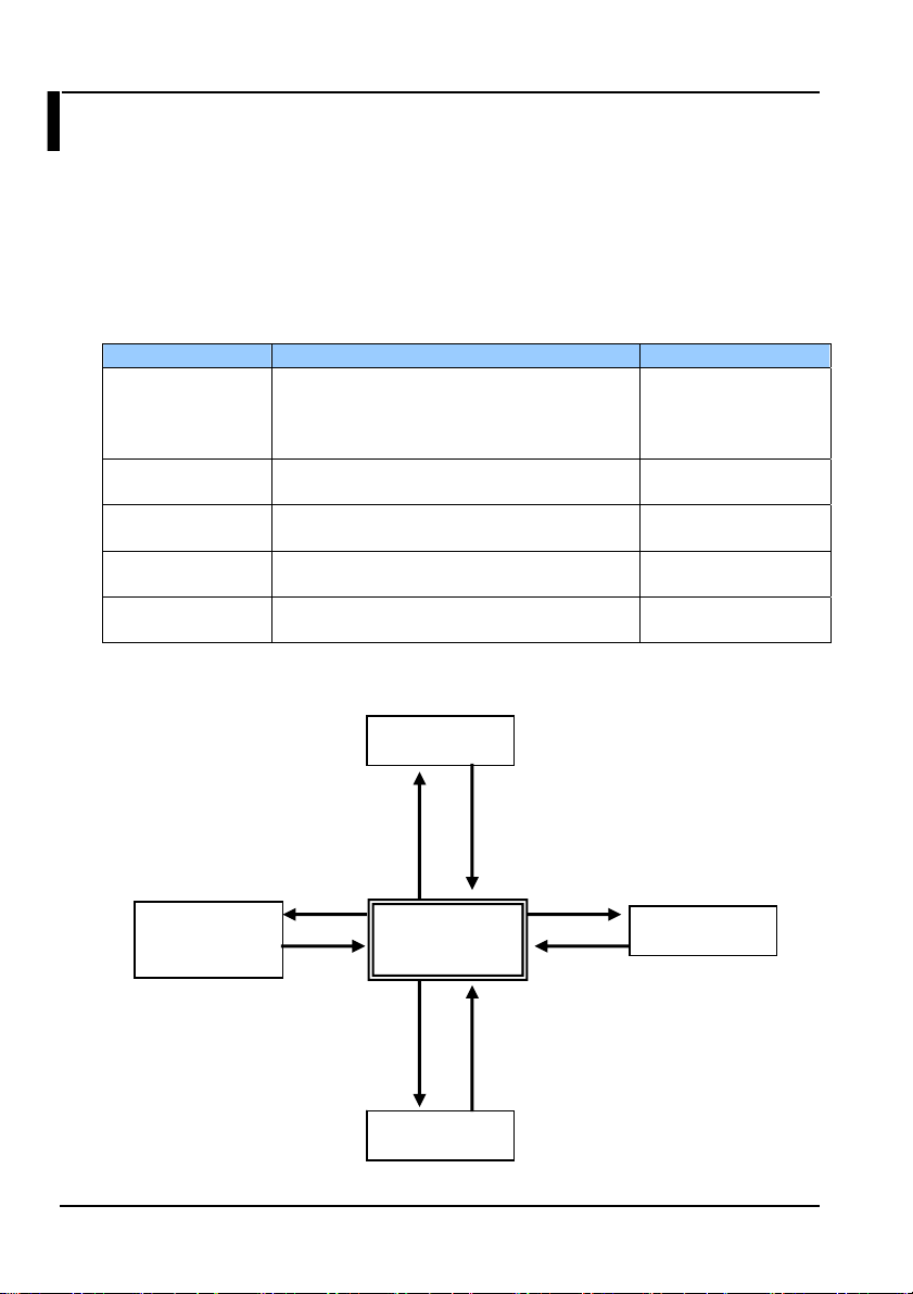
3.2 Modes
This instrument has five modes as shown in the table. When the power is turned
ON, the instrument starts up in normal measurement mode. You can press the
appropriate key to transition from normal measurement mode into the other
modes. When a USB cable is connected, the instrument switches to USB mode
automatically. When USB is disconnected, the instrument returns to normal
measuring mode.
3.2.1 List of Modes
Mode Functions Included Entering the Mode
Normal
measurement
mode
Setup mode Averaging setting. MAX hold setting.
Wavelength
setting mode
CAL setting mode User calibration function setting.
USB mode Remote control. Uploading the sensor head
3.2.2 Diagram of Relationship between Modes
Wavelength
measurement
mode
ENTER+SETUP key
Optical power measurement. Absolute value
measurement. Relative value measurement.
Range fixing. Switching the display units to
dBm/W.
NA setting. Sensor serial number display.
Setting the measured wavelength.
specific data to the TB200 from the PC.
ENTER key
SETUP key
λ key
SETUP mode
ormal
measurement
mode
CAL mode
Press the ENTER or SETUP key
four times in a row
Turn power ON and connect cables
Turn power OFF,
disconnect cables
ENTER key
Power ON
Press the SETUP
key.
Press the λ key
Press ENTER +
SETUP
Turn power ON and
connect cable.
USB mode
3-6
IM 735201-01E
Page 35

3.3 Absolute Value Measurement
3.3.1 Measuring Optical Power
When the power to the instrument is turned ON, measurement begins.
The optical power level is displayed in the measured value display area.
Figure 3-9 Example of an optical power measurement screen
3.3.2 Changing Units
Each time you press the dBm/W key, the display cycles through the following
options: “dBm” -> “W” (auto units) -> “mW” (fixed units) -> “dBm”.
dBm display W display (auto) mW display (fixed)
Figure 3-10 Display example of unit settings
Note
If the units are dB, differential measurement (relative value
・
measurement mode) is indicated.
Press the dBm/W key to switch to optical power measurement
・
(absolute value measurement mode).
IM 735201-01E
3-7
Page 36

3.3 Absolute Value Measurement
r
3.3.3 Fixing the Measuring Range (Range Hold)
You can fix the measuring range (range hold). This is useful when using the
analog out function.
1. Perform the operation from the initial screen in normal measurement mode
(Figure 3-1).
2. Press the RANGE key. The “HOLD” display and current range value blink
for five seconds.
Figure 3-11 Example of the range value display during range hold
Blinks for 5 sec. in synch. with the range value display,
then stops blinking.
3. After blinking, “HOLD” is displayed, and the range value is no longer
displayed. The fixed range setting is finalized. The instrument enters range
hold mode.
Figure 3-12 Example of the display when in range hold mode
To Change the Range Value
4. Press the UP or DOWN key while in range hold mode. The range goes up
or down.
5. The range blinks for five seconds in the area shown in Figure 3-11, then the
original screen returns (if REF is set, the REF value is displayed again).
Note
If the measuring range is fixed and the incoming light exceeds the
・
measuring range, the measured value blinks. If the upper limit of the
range is exceeded, “▲” is displayed. If the lower limit is not exceeded
“▼” is displayed.
Press the RANGE key again to return to AUTO mode.
・
Range value display
Displays the current range value fo
5 sec. (blinks)
3-8
IM 735201-01E
Page 37

3.3.4 Displaying Maximum Values (MAX Hold)
1. Perform the operation from the initial screen in normal measurement mode
(Figure 3-1).
2. Press the SETUP key. The setup mode screen appears.
3. Press the SETUP key once again. The MAX hold setting ON/OFF screen
appears.
Figure 3-13 Max hold setting screen
4. Each time you press the UP or DOWN key, “ON” or “OFF” blinks. Select
“ON”.
5. Press the ENTER key. The screen changes to the NA correction coefficient
setting screen (see Figure 3-4). The MAX hold setting is finalized.
6. Press the ENTER key two times. The instrument returns to the normal
measurement mode screen.
Figure 3-14 Normal measurement mode screen when the MAX hold setting
is enabled
Note
The MAX hold and REF functions cannot be used at the same time on
・
the instrument.
If you turn ON the REF function while the MAX hold function is enabled,
・
MAX hold is cancelled and the REF function is enabled.
3.3 Absolute Value Measurement
IM 735201-01E
3-9
Page 38

3.3 Absolute Value Measurement
3.3.5 Measuring after Setting the CAL Value
You can add an arbitrarily set user calibration value (CAL value) to the values
displayed in normal measurement mode. The available setting range is -10 dB to
+10 dB. The active power range and the setting range for the relative value
measurement reference value is shifted by the value of CAL. The ON status of the
user calibration function and the CAL value are saved even when the power is
turned OFF. Use for the correction made when performing calibration.
1. Perform the operation from the initial screen in normal measurement mode
(Figure 3-1).
2. Press the SETUP key while holding down the ENTER key. The CAL
setting ON/OFF screen appears. However, it does not appear when in
relative measurement mode. The transition only occurs from absolute
value measurement mode. If you transition to CAL setting mode, “CAL” is
displayed, and the display to the lower right of “CAL” blinks.
3. Each time you press the UP key, the display to the lower right of “CAL”
cycles through the following options: “OFF”, “Prev Val”, “Usr”, “OFF”.
Pressing the DOWN key cycles in the reverse order.
4. After selecting a CAL value (previous value), press the ENTER key.
The typical CAL setting is finalized.
Figure 3-15 Example of the CAL value setting screen
3-10
IM 735201-01E
Page 39

3.3 Absolute Value Measurement
5. You can set an arbitrary CAL value in 0.01 dB steps.
After setting the display to the lower right of “CAL” to “USr”, press the
ENTER key. The CAL detail setting screen appears.
6. Press the UP or DOWN key. The CAL value changes in steps of 0.01 dB.
The available setting range is -10 dBm to +10 dBm
Figure 3-16 Example of the CAL value detail setting screen
7. Press the ENTER key. The instrument returns to normal measurement
mode. The CAL detail setting is finalized.
Figure 3-17 Example of the normal measurement mode screen when
the CAL setting is enabled
IM 735201-01E
3-11
Page 40

3.4 Relative Value Measurement
Measuring the Optical Power Differential
You can display the difference (dB) from a reference value (REF).
1. In absolute value measurement mode, press the dBm/W key while holding
down the ENTER key. The measured value at the time the key was
pressed is set as the reference value, and relative measurement begins.
2. The units for relative measurement reference value are fixed at dBm.
There is no W unit display.
Absolute value measurement mode When REF is set
Figure 3-18 Example of display in absolute value measurement mode
when setting the reference (REF)
Note
To return to absolute value measurement, press the dBm/W key.
・
Each time you press the dBm/W key while holding down the ENTER
・
key, the reference value is updated.
Only measured values can be set as the reference value. Arbitrary
・
values cannot be specified.
3-12
IM 735201-01E
Page 41
Chapter 4 Measuring Using USB (Remote Control)
4.1 USB Communication Function
You can control the instrument using USB. You can read data and enter various
parameters from the PC. Also, a DLL and sample software are available on the
TB200 Utility CD in order to install the TB200 dedicated USB driver and easily
create control software. The following provides the USB communication
specifications and explains how to install the driver.
USB Communication Specification
Item Specification
USB standard Conforms to USB Version 1.1
Connector type B
Remote control function Provided (bulk transfer)
USB driver TB200 dedicated driver comes standard
(for Windows 2000/XP)
USB cable length* 2 m or less (shielded type)
* Attach a ferrite core (TDK: ZCAT1325-0530A or equivalent) to one end of the
USB cable, close to the instrument’s USB connector.
Driver/DLL Specifications and Operating Environment
Item System Requirements
OS Windows 2000/XP
Languages Microsoft Visual C++ 6.0
Microsoft Visual Basic 6.0
RAM 32 MB or more
Interface Windows 2000/XP with TB200 dedicated
USB driver installed.
Send delimiter (TB200 -> PC) CR+LF
Receive delimiter (PC -> TB200) CR+LF or LF only
CAUTION
During USB communications, do not turn the power to the PC and
TB200 OFF.
The driver and DLL are not guaranteed to be compatible with all PCs,
hubs, and other hardware.
IM 735201-01E
4-1
Page 42

4.2 Installing USB Drivers
Install the USB driver on the PC. Use the TB200 Utility CD that comes standard.
Follow the on-screen instructions.
Preparation
Turn the instrument ON, then connect the instrument to the PC using a USB
cable (insert the cable connector completely and firmly into the receptacle). The
instrument automatically enters USB mode, and USB is displayed (see section
2.2 and figure 2-6).
* USB cable: shielded cable of 2 m or more in length.
Installation
1. Place the enclosed TB200 Utility CD in the CD-ROM drive.
2. Turn the instrument ON, then connect the instrument to the PC using a
USB cable (insert the cable connector completely and firmly into the
receptacle). The Found New Hardware Wizard is displayed.
3. Click Next
4. Select Search for a suitable driver for my device. Click Next.
4-2
IM 735201-01E
Page 43

4.2 Installing USB Drivers
5. Select CD-ROM drives. Click Next.
6. Click Next.
7. Click Finish. The installation is complete
IM 735201-01E
4-3
Page 44

4.3 List of Commands
The following describes the commands available on the TB200.
The TB200 offers ASCII character strings in addition to input and output commands.
Also, the return values for setting commands and query commands are separate, so
there is no need to send commands and queries separately.
Command Notation Conventions and Meanings
1) Commands begin with a colon ( : ).
2) <wsp> means, enter a space.
3) <Value> means, enter value here.
4) ON|OFF means, enter either ON or OFF.
Command List
No.
Function Command Description Parameters Response
1 Data
request
2 Data
request with
status
3 Max value
data
request
4 Wavelength
setting
5 Check the
set
wavelength
6 NA
correction
function
enable/
disable
setting
:READ:POW? Returns the
:READ:POW:
STAT?
:READ:MAX? Returns the
:SENS:POW:
WAV<ws p>
<Value>
:SENS:POW:
WAV?
:SENS:CORR
:NA:STAT<ws
p> ON|OFF
current
measured value.
Returns the
current
measured value
and range
status.
current
maximum
measured value.
Sets the
wavelength
Returns the set
wavelength.
Turns NA
correction
function ON and
OFF
None Returns the current
None Returns the current
None
Returns the current
400-850
(1 step)
Units: nm
None Set as a three digit integer.
ON: Enabled
OFF: Disabled
measured value in Float
format. The units are the
same as those during
setting.
ERR#: See error list.
measured value in Float
format.
<Range status>
Over Range
Under Range
In Range
Average
ERR#: See error list.
maximum measured value
in Float format. The units
are the same as those
during setting.
ERR#: See error list.
OK: Setting complete
ERR#: See error list.
The units are fixed at nm.
ERR#: See error list.
OK: Setting complete
ERR#: See error list.
4-4
IM 735201-01E
Page 45

No.
Function Command Description Parameters Response
7 Check NA
correction
function
setting
status
8 Set NA
correction
Val ue
9 Check NA
correction
value
10 Setting the
measuring
range
11 Check
measuring
range
12 Set units of
measurement
13 Check units
of measurement
:SENS:CORR:
NA:STAT?
:SENS:CORR
:NA:VAL<wsp
><Value>
:SENS:CORR
:NA:VAL?
:SENS:POW:
RANG<wsp>
<Value>
:SENS:POW:
RANG?
:SENS:POW:
UNIT<wsp>
<Value>
:SENS:POW:
UNIT?
Returns the NA
correction
function setting
status.
Sets the NA
correction value.
Sets the data
internally
regardless of the
NA correction
function
ON/OFF.
Returns the
currently set NA
correction value.
Returns the
setting status of
the data
internally
regardless of the
NA correction
function
ON/OFF.
Sets
the measuring
range.
Returns the
status of the
current
measuring
range setting.
Sets the units for
the measured
value.
Returns the unit
setting status of
measured
values.
None ON: Enabled
0.500-2.000
:0.001step
None Decimal place 3 digits *.**
AUTO
+20 dBm
+10 dBm
0 dBm
-10 dBm
-20 dBm
-30 dBm
None AUTO
0: dBm
1: mW / µW /
nW auto
switching
2: mW fixed
display
None 0: dBm
4.3 List of Commands
OFF: Disabled
ERR#: See error list.
OK: Setting complete
ERR#: See error list.
ERR#: See error list.
OK: Setting complete
ERR#: See error list.
+20 dBm
+10 dBm
0 dBm
-10 dBm
-20 dBm
-30 dBm
ERR#: See error list.
OK: Setting complete
ERR#: See error list.
1: mW/µW/nW auto
switching
2: mW fixed display
ERR#: See error list.
IM 735201-01E
4-5
Page 46

4.3 List of Commands
No.
Function Command Description Parameters Response
14 Relative
value
measurement setting
15 Check
relative
setting
16 Check
relative
measurement
reference
value
17 User CAL
function
enable/
disable
setting
18 Check user
CAL
function
setting
status
19 Set user
CAL value
20 Check user
CAL value
21 Set
averaging
22 Check
averaging
setting
:SENS:POW:
REF:STAT
<wsp>ON|OF
F
:SENS:POW:
REF:STAT?
:SENS:POW:
REF:VAL?
:SENS:CORR
:CAL:STAT
<wsp>ON|OF
F
:SENS:CORR
:CAL:STAT?
:SENS:CORR
:CAL:VAL<ws
p><Value>
:SENS:CORR
:CAL:VAL?
:SENS:POW:
AVG < wsp >
ON|OFF
:SENS:POW:
AVG ?
Switches
between relative
and absolute
measurement.
Returns the
relative/absolute
value
measurement
status.
Returns the
relative
measurement
reference value.
Turns user CAL
function ON and
OFF
Returns the user
CAL function
setting status.
Sets the user
CAL value
Returns the user
CAL value.
Sets up
averaging.
Returns
the averaging
setting status.
ON: Relative
value
measurem
ent: dB
Absolute value
measurement
(dBm)
None ON: Relative value
None
***.** (symbol, 2-digit
ON: User CAL
ON status
OFF: User CAL
OFF status
None ON: User CAL ON status
***.** (symbol,
2-digit integer,
2-digit decimal).
The units are dB
Range: integer
from -10.00 to
+10.00, first 0 or
+ can be omitted
None ***.** (symbol, 2-digit
ON: Averaging
ON
OFF: Normal
measurement
None ON: Averaging ON
OK: Setting complete
ERR#: See error list.
measurement: dB
OFF: Absolute value
measurement: dBm
ERR#: See error list.
integer, 2-digit decimal).
units are dBm.
ERR#: See error list.
OK: Setting complete
ERR#: See error list.
OFF: User CAL OFF status
ERR#: See error list.
OK: Setting complete
ERR#: See error list.
integer, 2-digit decimal).
units are dB.
Range: -10.00 to +10.00.
ERR#: See error list.
OK: Setting complete
ERR#: See error list.
OFF: Normal
measurement
ERR#: See error list.
4-6
IM 735201-01E
Page 47

No.
Function Command Description Parameters Response
23 Max. value
measurement mode
setting
24 Check max
value
measurement mode
25 Get main
unit
(735201)
information
26 Get sensor
head
(735221)
information
27 Execute
zero set
28 Reset :SYST:RST Resets the
:SENS:POW:
MAX<wsp>
<Value>
:SENS:POW:
MAX?
:SYST:IDN? Returns main
Sets the
maximum value
measurement
mode.
Returns the
maximum value
measurement
mode setting
status.
unit information
:SYST:HEAD:
IDN?
Returns sensor
head
information.
:SYST:ZERO Executes an
Note
The command system conforms with SCPI. However only short (and
・
not long) form is supported.
Since spaces are used as separators, unneeded spaces inserted into
・
commands result in syntax errors.
Commands are case insensitive.
electrical ZERO.
setting
conditions to
their factory
defaults.
Installed sensor
head information
and wavelength
data are not
deleted.
ON: Max. value
measurement
mode ON +
reset max
measurement
value.
OFF: Normal
measurement
None ON: Max. value
None <maker>, <model>, <serial
None <maker>, <model>, <serial
None OK: Concluded
None OK: Concluded
4.3 List of Commands
OK: Setting complete
ERR#: See error list.
measurement mode ON
OFF: Normal
measurement
no.>, <firmware ver.>,
<options>
ERR#: See error list.
no.>
ERR#: See error list.
successfully
ERR#: See error list.
ZERO set can take up to 5
or 6 seconds.
The response occurs after
execution finishes.
successfully
ERR#: See error list.
IM 735201-01E
4-7
Page 48

4.3 List of Commands
Communication Errors
If a communication error occurs in remote control, a string comprising “ERR” plus
a number is sent.
Error List
Error Number Description Cause
ERR1 Command syntax
ERR2 Command
ERR3 System abnormality
error
execution error
error
Command not correct.
Parameters out of range.
Appears when in a mode that
precludes execution of the
command
Memory damaged, or other
hardware related trouble.
4-8
IM 735201-01E
Page 49

4.4 Sample Program
A DLL is provided to make creation of measurement programs easier.
4.4.1 Installing the DLL
The DLL is included on the TB200 Utility CD included with the sensor head.
For instructions on use, consult the ReadMe.txt file for the DLL.
4.4.2 Sample Software
The project file for the sample software that uses TB200.DLL is included on the
TB200 Utility CD.
This section describes how to use these sample programs.
Note
All DLLs and sample softwares in the CD that comes with the sensor
head are the same regardless of the sensor head.
For Visual C++
1. Place the TB200 Utility CD in the CD-ROM drive.
2. Copy the TB200.dll and VCSample.exe files from the VCSample folder on
the TB200 Utility CD to the same folder on the PC you are using.
3. Double-click VCSample.exe. The file opens.
4. Click Open. “Open success” is displayed. Click OK (in the popup screen).
IM 735201-01E
4-9
Page 50

4.4 Sample Program
5. Enter measurement conditions. After inputting the send command, click
Command (in the operation example, the wavelength is set).
When settings are complete, “OK” is displayed.
You can also display the currently set value and measured value. After
inputting the send command, click Command (in the operation example,
the set NA value is displayed).
6. Click Close to exit. “Close success” is displayed. Click OK (in the popup
screen).
7. To c lose the sample program, click OK.
4-10
IM 735201-01E
Page 51

4.4 Sample Program
For Visual Basic (VB)
1. Place the TB200 Utility CD in the CD-ROM drive.
2. Copy the TB200.dll and VBSample.exe files from the VBSample folder on
the TB200 Utility CD to the same folder on the PC you are using.
3. Double-click VBSample.exe. The file opens.
4. Click Open. “Open success” is displayed.
Click OK in the popup screen.
5. Enter measurement conditions. After inputting the send command, click
Command (in the operation example, the wavelength is set).
IM 735201-01E
4-11
Page 52

4.4 Sample Program
When settings are complete, “OK” is displayed.
You can also display the currently set value and measured value. After
inputting the send command, click Command (in the operation example,
the current measured value is displayed).
6. Click Close to exit. “Close success” is displayed. Click OK in the popup
screen.
7. To close the sample program, click the Close button “ X ”.
4-12
IM 735201-01E
Page 53

Chapter 5 Notes When Purchasing the Sensor Head by Itself
5.1 Uploading Sensor Specific Data
In order to satisfy sensor head operating characteristics, sensor specific data is
uploaded. This data is included in the TB200 Utility CD that comes with the
sensor head. Upload the data using your PC and USB cable. Note that if you
selected the combined calibration option at the time of purchase (suffix code
-CA1 or -CA3), the sensor specific data (calibration data) has already been
loaded into the TB200 Optical Powermeter, so this step is not necessary.
In the following cases, sensor-specific data must be uploaded before starting
measurement.
● When using a sensor head purchased by itself as an add-on.
● If the suffix code printed on the name plate on the rear panel of
the TB200 is -CA0.
Preparation
1. Install the USB driver (included) on the PC (see section 4.2 for the
installation procedure).
2. Turn the instrument ON, then connect the instrument to the PC using a
USB cable (insert the cable connector completely and firmly into the
receptacle). The instrument automatically enters USB mode, and USB is
displayed (see section 2.3).
Upload Procedure
1. Place the TB200 Utility CD in the CD-ROM drive.
2. Choose My Computer > CD-ROM > Utility.
3. Double-click the TB200DataUpLoad.exe file in the Utility folder.
The TB200DataUpLoad screen is displayed.
IM 735201-01E
5-1
Page 54

5.1 Uploading Sensor Specific Data
4. Click File Open. The Calibration File Select screen opens.
5. Select a data file from the Calibration Data folder. Click Open.
6. Click Data Upload. The upload finishes.
7. Click Exit.
Remove the USB cable. The instrument enters normal measurement mode
(use a safe procedure for removing the USB connection from the PC side).
Note
The uploaded correction data is unique to the sensor head.
・
When replacing it with a different sensor head, you must upload the
・
correction data for the new sensor head.
5-2
IM 735201-01E
Page 55

5.2 Displaying the Sensor Head Serial Number
The sensor head serial number of the calibration data currently stored in the
instrument is displayed.
Check whether it matches the serial number of the sensor head to be used.
This is only a mode for checking the number, and it cannot be edited. The last six
digits of the serial number are displayed
1. Perform the operation from the initial screen in normal measurement mode
(Figure 3-1).
2. Press the SETUP key. The setup mode screen appears.
3. Press the SETUP key three more times. The sensor head serial number is
displayed.
Figure 5-1 Sensor head serial number reference screen
Sensor head S/N
Last 6 digits
Ex. (27D234567)
IM 735201-01E
5-3
Page 56

Chapter 6 Maintenance
6.1 Error Messages
Overrange Error
The display blinks if the measured optical power level
exceeds the maximum measurable value.
It also blinks if, when using range hold, the value exceeds
the range upper limit.
Always note the measurable values of each range
Figure 6-1 Overrange error
Underrange Error
The display blinks if the measured optical power level falls
below the minimum measurable value.
It also blinks if, when using range hold, the value falls below
the range lower limit.
Always note the measurable values of each range.
Figure 6-2 Underrange error
Reference Value Out of Range Error
Displayed when the measured value used for setting or
updating the relative measurement reference value is
outside the valid range.
The high or low level error display appears for one second,
then the unit returns to the previous measurement mode.
Figure 6-3 High level error
Figure 6-4 Low level error
Exceeded the upper limit: high level error
Fell below the lower limit: low level error.
IM 735201-01E
6-1
Page 57

6.1 Error Messages
Figure 6-5 Resume error
Figure 6-6 CAL value
setting error
Resume Error
If the Resume value was not saved successfully, the
Resume error appears the next time the instrument is
started.
To cancel a resume error, press the ENTER key or turn the
power OFF and restart.
mode screen appears.
The normal measurement
CAL Value Setting Error
This is displayed if calibration data was not input or was lost.
Upload sensor specific data (calibration data) via USB (see
section 5.1).
Note that if you selected the combined calibration option at
the time of purchase (suffix code -CA0), the sensor specific
data (calibration data) has already been loaded into the
TB200 Optical Powermeter.
6-2
IM 735201-01E
Page 58

6.2 Troubleshooting
The following should be checked if the instrument is not functioning as expected.
Cannot take measurements
Immediately after turning the power ON, the measured value blinks and
measurements cannot be taken.
-> Is range hold selected (the hold indicator is displayed)?
Press the RANGE key. This clears the range hold.
(Example of possible problem: When using the previous value, the range is
held at a high level resulting in a continuous measured value of “under
error.”)
The instrument doesn’t work even though the power is ON.
1) Are the correct batteries installed?
-> Use only AA alkaline dry cells.
-> Check the polarity/orientation of the batteries.
2) Is there charge remaining in the batteries?
3) Is one or both of the batteries spent?
-> Replace both batteries (at the same time).
(Leakage can occur when using an old and new battery together, and can
result in damage to the instrument.)
4) Is the power cord for the AC adapter connected correctly?
5) Are you using the dedicated AC adapter that came with the instrument?
-> Never use an AC adapter or power cable other than the dedicated ones
available for use with this instrument, as damage can result.
Normal measured values are not displayed.
1) Do the instrument’s measurement conditions match the light being measured?
-> Edit the measurement conditions using the SETUP key.
2) Is CORR VAL blinking?
-> Turn the user calibration function OFF during normal measurement.
3) Is the sensor head connector connected correctly?
-> Check the connections. Align the connector tab with the groove, then push
all the way in.
If the connection is not sound, measurements will be inaccurate.
Cannot transfer data via USB.
1) Did you install the USB driver on the PC?
-> Use the accessory TB200 UTILITY CD.
2) Is the USB cable properly connected?
3) Are you using the dedicated AC adapter?
IM 735201-01E
6-3
Page 59

6.3 Periodic Calibration
Periodic Calibration
1) Periodic calibration maintains the normal performance of the instrument over
long periods of time, and is an effective means of quickly identifying any
malfunctions that may occur.
2) The sensor head uses an optical filter based on glass material. If the optical
filter is subjected to high powered near-infrared light of approximately 400 nm
for long durations, reduced transmissivity may result. Additionally, the
sensitivity of the sensor may be reduced by a few percent due to any
reductions in the transmissivity. For precise measurements, it is
recommended to calibrate the instrument periodically (every six months).
6-4
IM 735201-01E
Page 60

Chapter 7 Specifications
7.1 Specifications
TB200 Optical Power Meter: 735201
Environmental Conditions
Item Environmental Condi tion
Operation-guaranteed
temperature/humidity
conditions
Storage
temperature/humidity
Electrical Specifications
Item Specification
Display 7-segment, 4-digit, w/ backlight
Display resolution
Unit display
Wavelength setting range 400 to 850 nm
Wavelength sensitivity
compensation increment
Range selection AUTO/HOLD
NA compensation range 0.500 to 2.000 (0.001 increments)
Optical power display range 1 µW (-30 dBm) to 100 mW (+20 dBm)
Measurement interval Approx. 100 msec
Backlight
Analog output
Interface USB (B connector)
Sensor head
Power supply
Accessories User’s Manual, AC adapter, UM connector protective cap
Safety, EMC Note)
Note) Applies to products with CE marks. For all other products, contact your neare st
YOKOGAWA dealer.
IM 735201-01E
Body: 5 to 40°C (ambient temp erature), 20 to 80% (no
condensation)
-20 to +60°C (ambient temperature), 20 to 80% (no
condensation)
0.01 dB (When W unit is selected, fl oating poin t w /
4 digits past decimal poin t)
Absolute value: dBm, mW, µW , nW
Incremental value: d B
1 nm
Lights when backlight key is pressed, and goes out w hen
key is pressed again.
0 to 2 V connector: UM connector (made by Hirose
Electric)
Model: 735221 (Model name of sensor head becomes
735201 when -CA1 or -CA3 integrated calibration is
selected. However, its performance is the same.)
AC adapter (rated input voltage: 100 to 240 V, 50/60 Hz,
0.24 to 0.13 A) 7 VA AA alkali dry cell (operation time:
approx. 24 hours)
Safety: EN61010-1,
(Out of conformance since December 1, 2010.)
EMC: EN61326-1 ClassA, Table2 (for use in industrial
locations)Pollution degree 2, Over voltage category II
7-1
Page 61

7.1 Specifications
Sensor Head for TB200: 735221
Environmental Conditions
Item Environmental Condition
Operation-guaranteed
temperature/humidity
Storage
temperature/humidity
Electrical/Optical Characteristics
Item Specification
Wavelength range 400 to 850 nm
Light-receiving element Si-PD
Received light power
range
Max. light receiving level +20 dBm (100 mW) Note 1)
Max. power density 5 mW/mm2 Note 1)
Uncertainty at reference
conditions
Input type Spatial light
Accessories
Note 1) Condition: λ= 405 nm
Note 2) Reference conditions:
(1) Reference temperature: 23 °C ±3 °C
(2) Reference wavelength: λ= 405 nm (Add 0.5% when the wavelength
(3) Reference power: 1 mW
(4) Reference beam shape: Distribution: Gaussian distribution,
(5) Spectral width: 1 nm or less
(6) Light receiving position: Mechanical center
(7) Wavelength setting error: Within _0.5 nm
(8) Not including secular changes of measuring equipment
(9) Uncertainty inclusion coefficient: k = 2
* Uncertainty when only sensor head is sold. For details on
uncertainty when the integrated calibration option is applied, refer
to the “Remarks” column of the Model and Suffix Code table.
Note 3) Compensation values for this sensor head are provided in the TB200
Utility CD.
These performance values are for when this data is uploaded to the
TB200 Optical Power Meter for use.
0 to +60°C (ambient temperature), 20 to 80% (no
condensation)
-20 to +60°C (ambient temperature), 20 to 80%
(no condensation)
1 µW (-30 dBm) to 100 mW (+20 dBm) Note 1)
±4% Note 2)
TB200 Utility CD Note 3)
Sensor protective cap
is in the range of 400 to 420 nm.)
Radiated NA : 0.2, diffused light (50GI fiber output)
7-2
IM 735201-01E
Page 62

7.1 Specifications
Combined Calibration Specifications
The sensor head (735221) and TB200 Optical Powermeter (735201) are calibrated
together. If you selected the combined calibration option at the time of purchase,
the electrical/optical characteristics of the sensor head are as given below (suffix
code -CA1 or -CA3). The sensor head calibration data is written to the TB200
Optical Powermeter (735201), and the model of the sensor head becomes that
of the main unit (735201).
Electrical/Optical Characteristics (With the Combined Calibration Option)
Item Specification
Wavelength range 400 to 850 nm
Light-receiving element Si-PD
Received light power
range
Max. light receiving level +20 dBm (100 mW) Note 1)
Max. power density 5 mW/mm2 Note 1)
Uncertainty at reference
conditions
Input type Spatial light
Accessories
Note 1) Condition: λ= 405 nm
Note 2) Reference conditions:
(1) Reference temperature: 23 °C ±3 °C
(2) Reference wavelength: λ= 405 nm (Add 0.5% when the wavelength
(3) Reference power: 1 mW
(4) Reference beam shape: Distribution: Gaussian distribution,
(5) Spectral width: 1 nm or less
(6) Light receiving position: Mechanical center
(7) Wavelength setting error: Within _0.5 nm
(8) Not including secular changes of measuring equipment
(9) Uncertainty inclusion coefficient: k = 2
* Uncertainty when only sensor head is sold. For details on
uncertainty when the integrated calibration option is applied, refer
to the “Remarks” column of the Model and Suffix Code table.
Note 3) Compensation values for this sensor head are provided in the TB200
Utility CD.
These performance values are for when this data is uploaded to the
TB200 Optical Power Meter for use.
1 µW (-30 dBm) to 100 mW (+20 dBm) Note 1)
±2.5 %(405 nm)±3.0 %(660 nm 785 nm)
Note 2)
TB200 Utility CD Note 3)
Sensor protective cap
is in the range of 400 to 420 nm.)
660 nm calibration option: λ= 660 nm
785 nm calibration option: λ= 405 nm
Radiated NA: 0.2, diffused light (50GI fiber output)
IM 735201-01E
7-3
Page 63

7.1 Specifications
Accessories
Accessory Description
TB200 Utility CD
USB driver for Windows 2000/XP
API
Calibration data
Calibration data upload tool
7-4
IM 735201-01E
Page 64

7.2 External Dimensions
Figure 7-1 TB200 Optical Powermeter’s external dimensions
UM connector
Units: mm
IM 735201-01E
7-5
Page 65

7.2 External Dimensions
Figure 7-2 Sensor head’s external dimensions
M3
Fig. 5-2 Sensor head external dimensions
Units: mm
7-6
IM 735201-01E
Page 66
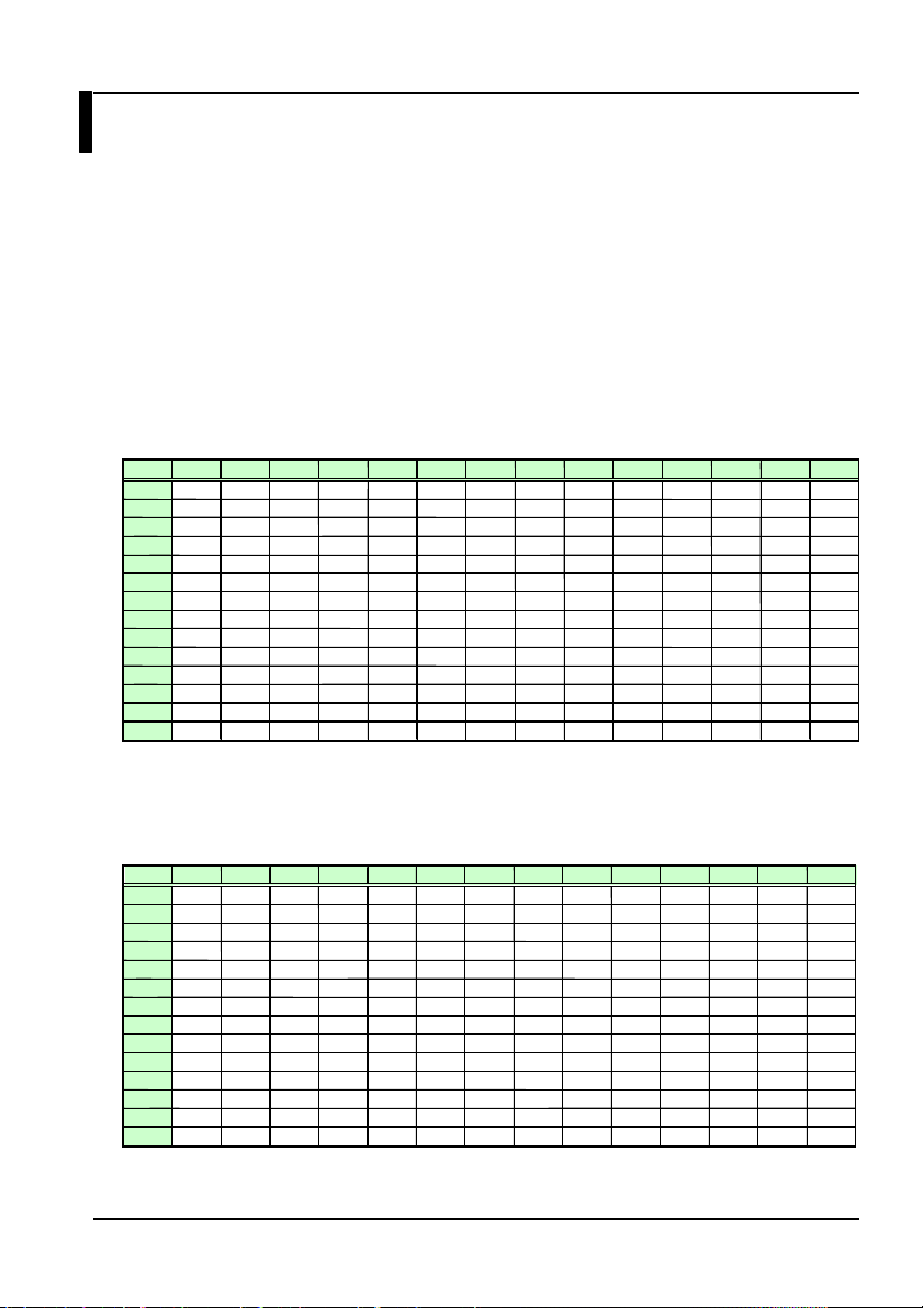
Appendix
Appendix 1 Table of NA Correction Coef ficients
Use this table when setting the numerical aperture (see section 3.1.2). You can
correct the angle dependency of the light accepted by the sensor head
resulting from the aperture. This section includes seven different NA correction
coefficient tables based on wavelength and NA. Contact your nearest
Yokogawa representative if none of the correction tables below match your
conditions.
The horizontal axis is S polarization (perpendicular to the plane of polarization)
and the vertical axis is P polarization (parallel to th e plane of polarization).
Wavelength: 405 nm, NA = 0.65
RIM 30% 35% 40% 45% 50% 55% 60% 65% 70% 75% 80% 85% 90% 95%
30% 1.148 1.148 1.149 1.149 1.149 1.15 1.15 1.15 1.15 1.151 1.151 1.151 1.151 1.151
35% 1.153 1.153 1.153 1.153 1.154 1.154 1.154 1.154 1.155 1.155 1.155 1.155 1.155 1.155
40% 1.157 1.157 1.157 1.157 1.158 1.158 1.158 1.158 1.158 1.158 1.159 1.159 1.159 1.159
45% 1.161 1.161 1.161 1.161 1.161 1.161 1.162 1.162 1.162 1.162 1.162 1.162 1.162 1.162
50% 1.164 1.164 1.164 1.165 1.165 1.165 1.165 1.165 1.165 1.165 1.165 1.165 1.165 1.165
55% 1.167 1.167 1.168 1.168 1.168 1.168 1.168 1.168 1.168 1.168 1.168 1.168 1.168 1.168
60% 1.17 1.171 1.171 1.171 1.171 1.171 1.171 1.171 1.171 1.171 1.171 1.171 1.171 1.171
65% 1.173 1.173 1.173 1.174 1.174 1.174 1.174 1.174 1.174 1.174 1.174 1.174 1.174 1.174
70% 1.176 1.176 1.176 1.176 1.176 1.176 1.176 1.176 1.176 1.176 1.176 1.176 1.176 1.176
75% 1.179 1.179 1.179 1.179 1.179 1.179 1.179 1.179 1.179 1.179 1.179 1.179 1.179 1.178
80% 1.181 1.181 1.181 1.181 1.181 1.181 1.181 1.181 1.181 1.181 1.181 1.181 1.181 1.181
85% 1.184 1.184 1.183 1.183 1.183 1.183 1.183 1.183 1.183 1.183 1.183 1.183 1.183 1.183
90% 1.186 1.186 1.186 1.186 1.186 1.186 1.185 1.185 1.185 1.185 1.185 1.185 1.185 1.185
95% 1.188 1.188 1.188 1.188 1.188 1.188 1.187 1.187 1.187 1.187 1.187 1.187 1.187 1.187
Wavelength: 405 nm, NA = 0.85
RIM 30% 35% 40% 45% 50% 55% 60% 65% 70% 75% 80% 85% 90% 95%
30% 1.302 1.302 1.302 1.302 1.302 1.302 1.302 1.302 1.302 1.302 1.302 1.302 1.301 1.301
35% 1.312 1.312 1.312 1.312 1.312 1.312 1.311 1.311 1.311 1.311 1.311 1.311 1.311 1.31
40% 1.321 1.321 1.321 1.321 1.321 1.32 1.32 1.32 1.32 1.32 1.319 1.319 1.319 1.319
45% 1.33 1.33 1.329 1.329 1.329 1.328 1.328 1.328 1.328 1.327 1.327 1.327 1.327 1.326
50% 1.338 1.337 1.337 1.337 1.336 1.336 1.336 1.335 1.335 1.335 1.334 1.334 1.334 1.333
55% 1.345 1.345 1.344 1.344 1.343 1.343 1.343 1.342 1.342 1.341 1.341 1.341 1.34 1.34
60% 1.352 1.352 1.351 1.351 1.35 1.35 1.349 1.349 1.348 1.348 1.347 1.347 1.347 1.346
65% 1.359 1.358 1.358 1.357 1.356 1.356 1.355 1.355 1.354 1.354 1.353 1.353 1.353 1.352
70% 1.365 1.364 1.364 1.363 1.362 1.362 1.361 1.361 1.36 1.36 1.359 1.359 1.358 1.358
75% 1.371 1.37 1.37 1.369 1.368 1.368 1.367 1.366 1.366 1.365 1.365 1.364 1.364 1.363
80% 1.377 1.376 1.375 1.374 1.374 1.373 1.372 1.372 1.371 1.37 1.37 1.369 1.369 1.368
85% 1.382 1.381 1.381 1.38 1.379 1.378 1.377 1.377 1.376 1.376 1.375 1.374 1.374 1.373
90% 1.388 1.387 1.386 1.385 1.384 1.383 1.382 1.382 1.381 1.38 1.38 1.379 1.379 1.378
95% 1.393 1.392 1.391 1.39 1.389 1.388 1.387 1.387 1.386 1.385 1.384 1.384 1.383 1.383
IM 735201-01E
App-1
Page 67

Table of NA Correction Coefficients
A
Wavelength: 660 nm, NA = 0.6
RIM 30% 35% 40% 45% 50% 55% 60% 65% 70% 75% 80% 85% 90% 95%
30% 1.104 1.104 1.103 1.103 1.103 1.102 1.102 1.102 1.101 1.101 1.101 1.101 1.100 1.100
35% 1.108 1.108 1.107 1.107 1.106 1.106 1.106 1.105 1.105 1.105 1.104 1.104 1.104 1.104
40% 1.112 1.111 1.111 1.110 1.110 1.109 1.109 1.109 1.108 1.108 1.108 1.107 1.107 1.107
45% 1.115 1.114 1.114 1.113 1.113 1.112 1.112 1.112 1.111 1.111 1.111 1.110 1.110 1.110
50% 1.118 1.117 1.117 1.116 1.116 1.115 1.115 1.114 1.114 1.114 1.113 1.113 1.113 1.112
55% 1.121 1.120 1.119 1.119 1.118 1.118 1.117 1.117 1.117 1.116 1.116 1.115 1.115 1.115
60% 1.123 1.122 1.122 1.121 1.121 1.120 1.120 1.119 1.119 1.119 1.118 1.118 1.117 1.117
65% 1.126 1.125 1.124 1.124 1.123 1.123 1.122 1.122 1.121 1.121 1.120 1.120 1.120 1.119
70% 1.128 1.127 1.127 1.126 1.125 1.125 1.124 1.124 1.123 1.123 1.123 1.122 1.122 1.121
75% 1.130 1.129 1.129 1.128 1.127 1.127 1.126 1.126 1.125 1.125 1.125 1.124 1.124 1.123
80% 1.132 1.131 1.131 1.130 1.129 1.129 1.128 1.128 1.127 1.127 1.127 1.126 1.126 1.125
85% 1.134 1.133 1.133 1.132 1.131 1.131 1.130 1.130 1.129 1.129 1.128 1.128 1.128 1.127
90% 1.136 1.135 1.135 1.134 1.133 1.133 1.132 1.132 1.131 1.131 1.130 1.130 1.129 1.129
95% 1.138 1.137 1.136 1.136 1.135 1.134 1.134 1.133 1.133 1.132 1.132 1.131 1.131 1.131
Wavelength: 660 nm, NA = 0.65
RIM 30% 35% 40% 45% 50% 55% 60% 65% 70% 75% 80% 85% 90% 95%
30% 1.125 1.125 1.124 1.123 1.123 1.122 1.122 1.121 1.121 1.121 1.120 1.120 1.119 1.119
35% 1.130 1.129 1.128 1.128 1.127 1.127 1.126 1.126 1.125 1.125 1.124 1.124 1.124 1.123
40% 1.134 1.133 1.133 1.132 1.131 1.131 1.130 1.130 1.129 1.129 1.128 1.128 1.127 1.127
45% 1.138 1.137 1.136 1.136 1.135 1.134 1.134 1.133 1.133 1.132 1.132 1.131 1.131 1.131
50% 1.142 1.141 1.140 1.139 1.139 1.138 1.137 1.137 1.136 1.136 1.135 1.135 1.134 1.134
55% 1.145 1.144 1.143 1.143 1.142 1.141 1.141 1.140 1.139 1.139 1.138 1.138 1.137 1.137
60% 1.148 1.147 1.146 1.146 1.145 1.144 1.144 1.143 1.142 1.142 1.141 1.141 1.140 1.140
65% 1.151 1.150 1.149 1.148 1.148 1.147 1.146 1.146 1.145 1.145 1.144 1.143 1.143 1.142
70% 1.154 1.153 1.152 1.151 1.150 1.150 1.149 1.148 1.148 1.147 1.147 1.146 1.146 1.145
75% 1.157 1.156 1.155 1.154 1.153 1.152 1.152 1.151 1.150 1.150 1.149 1.149 1.148 1.147
80% 1.159 1.158 1.157 1.156 1.155 1.155 1.154 1.153 1.153 1.152 1.151 1.151 1.150 1.150
85% 1.162 1.161 1.160 1.159 1.158 1.157 1.156 1.156 1.155 1.154 1.154 1.153 1.153 1.152
90% 1.164 1.163 1.162 1.161 1.160 1.159 1.159 1.158 1.157 1.157 1.156 1.155 1.155 1.154
95% 1.166 1.165 1.164 1.163 1.162 1.161 1.161 1.160 1.159 1.159 1.158 1.157 1.157 1.156
pp-2
IM 735201-01E
Page 68

Table of NA Correction Coefficients
Wavelength: 785 nm, NA = 0.45
RIM 30% 35% 40% 45% 50% 55% 60% 65% 70% 75% 80% 85% 90% 95%
30% 1.006 1.006 1.005 1.004 1.004 1.004 1.003 1.003 1.002 1.002 1.002 1.001 1.001 1.001
35% 1.007 1.006 1.006 1.005 1.005 1.004 1.004 1.004 1.003 1.003 1.002 1.002 1.002 1.001
40% 1.008 1.007 1.007 1.006 1.006 1.005 1.005 1.004 1.004 1.004 1.003 1.003 1.003 1.002
45% 1.009 1.008 1.007 1.007 1.006 1.006 1.005 1.005 1.005 1.004 1.004 1.004 1.003 1.003
50% 1.009 1.009 1.008 1.007 1.007 1.006 1.006 1.006 1.005 1.005 1.004 1.004 1.004 1.004
55% 1.010 1.009 1.009 1.008 1.007 1.007 1.007 1.006 1.006 1.005 1.005 1.005 1.004 1.004
60% 1.010 1.010 1.009 1.009 1.008 1.008 1.007 1.007 1.006 1.006 1.006 1.005 1.005 1.005
65% 1.011 1.010 1.010 1.009 1.009 1.008 1.008 1.007 1.007 1.006 1.006 1.006 1.005 1.005
70% 1.011 1.011 1.010 1.010 1.009 1.009 1.008 1.008 1.007 1.007 1.007 1.006 1.006 1.006
75% 1.012 1.011 1.011 1.010 1.009 1.009 1.009 1.008 1.008 1.007 1.007 1.007 1.006 1.006
80% 1.012 1.012 1.011 1.010 1.010 1.009 1.009 1.009 1.008 1.008 1.007 1.007 1.007 1.007
85% 1.013 1.012 1.011 1.011 1.010 1.010 1.009 1.009 1.009 1.008 1.008 1.008 1.007 1.007
90% 1.013 1.012 1.012 1.011 1.011 1.010 1.010 1.009 1.009 1.009 1.008 1.008 1.008 1.007
95% 1.014 1.013 1.012 1.012 1.011 1.011 1.010 1.010 1.009 1.009 1.009 1.008 1.008 1.008
Wavelength: 785 nm, NA = 0.5
RIM 30% 35% 40% 45% 50% 55% 60% 65% 70% 75% 80% 85% 90% 95%
30% 1.008 1.007 1.006 1.006 1.005 1.005 1.004 1.004 1.003 1.003 1.002 1.002 1.001 1.001
35% 1.009 1.008 1.007 1.007 1.006 1.006 1.005 1.005 1.004 1.004 1.003 1.003 1.002 1.002
40% 1.010 1.009 1.008 1.008 1.007 1.007 1.006 1.006 1.005 1.005 1.004 1.004 1.003 1.003
45% 1.011 1.010 1.009 1.009 1.008 1.007 1.007 1.006 1.006 1.005 1.005 1.005 1.004 1.004
50% 1.012 1.011 1.010 1.009 1.009 1.008 1.008 1.007 1.007 1.006 1.006 1.005 1.005 1.005
55% 1.012 1.011 1.011 1.010 1.009 1.009 1.008 1.008 1.007 1.007 1.007 1.006 1.006 1.005
60% 1.013 1.012 1.011 1.011 1.010 1.010 1.009 1.009 1.008 1.008 1.007 1.007 1.006 1.006
65% 1.014 1.013 1.012 1.011 1.011 1.010 1.010 1.009 1.009 1.008 1.008 1.007 1.007 1.007
70% 1.014 1.013 1.013 1.012 1.011 1.011 1.010 1.010 1.009 1.009 1.008 1.008 1.008 1.007
75% 1.015 1.014 1.013 1.013 1.012 1.011 1.011 1.010 1.010 1.009 1.009 1.009 1.008 1.008
80% 1.015 1.015 1.014 1.013 1.013 1.012 1.011 1.011 1.010 1.010 1.010 1.009 1.009 1.008
85% 1.016 1.015 1.014 1.014 1.013 1.012 1.012 1.011 1.011 1.010 1.010 1.010 1.009 1.009
90% 1.016 1.016 1.015 1.014 1.014 1.013 1.012 1.012 1.011 1.011 1.011 1.010 1.010 1.009
95% 1.017 1.016 1.015 1.015 1.014 1.013 1.013 1.012 1.012 1.011 1.011 1.011 1.010 1.010
Wavelength: 785 nm, NA = 0.55
RIM 30% 35% 40% 45% 50% 55% 60% 65% 70% 75% 80% 85% 90% 95%
30% 1.010 1.009 1.008 1.007 1.007 1.006 1.005 1.005 1.004 1.004 1.003 1.003 1.002 1.002
35% 1.011 1.010 1.010 1.009 1.008 1.007 1.007 1.006 1.006 1.005 1.005 1.004 1.004 1.003
40% 1.013 1.012 1.011 1.010 1.009 1.008 1.008 1.007 1.007 1.006 1.006 1.005 1.005 1.004
45% 1.014 1.013 1.012 1.011 1.010 1.010 1.009 1.008 1.008 1.007 1.007 1.006 1.006 1.005
50% 1.015 1.014 1.013 1.012 1.011 1.010 1.010 1.009 1.009 1.008 1.008 1.007 1.007 1.006
55% 1.016 1.015 1.014 1.013 1.012 1.011 1.011 1.010 1.010 1.009 1.009 1.008 1.008 1.007
60% 1.016 1.015 1.014 1.014 1.013 1.012 1.012 1.011 1.010 1.010 1.009 1.009 1.008 1.008
65% 1.017 1.016 1.015 1.014 1.014 1.013 1.012 1.012 1.011 1.011 1.010 1.010 1.009 1.009
70% 1.018 1.017 1.016 1.015 1.014 1.014 1.013 1.013 1.012 1.011 1.011 1.010 1.010 1.009
75% 1.019 1.018 1.017 1.016 1.015 1.014 1.014 1.013 1.013 1.012 1.012 1.011 1.011 1.010
80% 1.019 1.018 1.017 1.017 1.016 1.015 1.015 1.014 1.013 1.013 1.012 1.012 1.011 1.011
85% 1.020 1.019 1.018 1.017 1.017 1.016 1.015 1.015 1.014 1.013 1.013 1.012 1.012 1.011
90% 1.021 1.020 1.019 1.018 1.017 1.016 1.016 1.015 1.015 1.014 1.013 1.013 1.012 1.012
95% 1.021 1.020 1.019 1.019 1.018 1.017 1.016 1.016 1.015 1.015 1.014 1.014 1.013 1.013
IM 735201-01E
App-3
Page 69

A
Appendix 2 Table of 7-Segment Display Characters
0 1 2 3 4 5 6 7
8 9 /
A B C D E F G H
I J K L M N O P
Q R S T U V W X
Y Z
pp-4
IM 735201-01E
 Loading...