

Page 1

Time Interval Analyzer
Communication Interface
IM 704510-17E
1st Edition
Page 2

Foreword
Notes
Thank you for purchasing the YOKOGAWA TA720 Time Interval Analyzer.
This Communication Interface User’s Manual describes the functions of the
communication interface and command communications. To ensure correct use, please
read this manual thoroughly before beginning operation.
After reading the manual, keep it in a convenient location for quick reference whenever a
question arises during operation of the software.
The following manual is also provided in addition to this manual. Read them along with
this manual.
Manual Title Manual No. Description
TA720 User’s Manual IM 704510-01E Explains all functions and procedures of the
TA720 excluding the command communication
functions.
• The contents of this manual are subject to change without prior notice as a result of
continuing improvements to the instrument’s performance and functions.
• Every effort has been made in the preparation of this manual to ensure the accuracy
of its contents. However, should you have any questions or find any errors, please
contact your nearest YOKOGAWA dealer as listed on the back cover of this manual.
• Copying or reproducing all or any part of the contents of this manual without the
permission of Yokogawa Electric Corporation is strictly prohibited.
• The TCP/IP software of this product and the document concerning the TCP/IP
software have been developed/created by YOKOGAWA based on the BSD
Networking Software, Release 1 that has been licensed from California University.
Trademarks
Revisions
• Microsoft, MS-DOS, and Windows are either registered trademarks or trademarks of
Microsoft Corporation in the United States and/or other countries.
• Adobe, Acrobat, and PostScript are trademarks of Adobe Systems Incorporated.
• For purposes of this manual, the TM and ® symbols do not accompany their
respective trademark names or registered trademark names.
• Other company and product names are trademarks or registered trademarks of their
respective companies.
1st Edition: September 2002
Disk No. HF16
1st Edition : September 2002 (YK)
All Rights Reserved, Copyright © 2002 Yokogawa Electric Corporation
IM 704510-17E
i
Page 3

How to Use This Manual
Structure of the Manual
This User’s Manual consists of the following sections:
Chapter 1 GP-IB Communication Interface
Describes the setup procedures for using the GP-IB communication
interface.
Chapter 2 Ethernet Communication Interface (Option)
Describes the setup procedures for using the Ethernet communication
interface.
Chapter 3 Program Syntax and Programming
Describes the program syntax and points to note when creating the
programs.
Chapter 4 Commands
Describes all the commands one by one.
Chapter 5 Status Reports
Describes the status byte, various registers, queues, and other
information.
Chapter 6 Sample Programs
Introduces program examples made using Visual Basic.
Appendix
Describes reference material such as an ASCII character code table.
Index
Gives an index.
Conventions Used in This Manual
• Conventions
Type Symbol Meaning
Unit k 1000 Example: 100 kHz
Symbols
• Symbols Used in the Syntax
The following table indicates symbols that are used in the syntax mainly in chapter 3.
These symbols are referred to as BNF (Backus-Naur Form) symbols. For a
description of the symbols used with the data (conditions and values that are written
following a space after the program header), see pages 3-5 and 3-6.
Symbol Meaning Example Entry Example
<> Defined value WINDow<x> <x>=1 to 16 WINDOW2
{} Select from values given in {} MODE {AUTO|MANual} MODE AUTO
| Exclusive OR MODE {AUTO|MANual} MODE AUTO
[] Can be omitted :MEASure[:MODE]
... Can be repeated
K 1024 Example: 128 KB (memory size)
Note
Describes useful information.
ii IM 704510-17E
Page 4

Contents
1
Foreword ......................................................................................................................................... i
How to Use This Manual .................................................................................................................ii
Chapter 1 GP-IB Communication Interface
1.1 Names and Functions of the Parts Related to GP-IB Communications ........................ 1-1
1.2 Connecting the GP-IB Cable ......................................................................................... 1-2
1.3 GP-IB Communication Capabilities and Specifications ................................................. 1-3
1.4 Settings on the TA720 ................................................................................................... 1-5
1.5 Responses to Interface Messages ................................................................................ 1-6
Chapter 2 Ethernet Communication Interface (Option)
2.1 Names and Functions of the Parts Related to Ethernet Communications..................... 2-1
2.2 Ethernet Communications Functions and Specifications............................................... 2-2
2.3 Connection Using the Ethernet Communication Interface ............................................. 2-3
2.4 Setting the TA720 .......................................................................................................... 2-4
Chapter 3 Program Syntax and Programming
3.1 Messages ...................................................................................................................... 3-1
3.2 Commands .................................................................................................................... 3-3
3.3 Responses ..................................................................................................................... 3-4
3.4 Data ............................................................................................................................... 3-5
3.5 Synchronization with the Controller ............................................................................... 3-7
2
3
4
5
6
App
Chapter 4 Commands
4.1 List of Commands .......................................................................................................... 4-1
4.2 ASCale Group................................................................................................................ 4-8
4.3 CALCulation Group........................................................................................................ 4-9
4.4 COMMunicate Group ................................................................................................... 4-25
4.5 DISPlay Group ............................................................................................................. 4-27
4.6 FILE Group .................................................................................................................. 4-31
4.7 HCOPy Group.............................................................................................................. 4-34
4.8 HHIStogram<x> and THIStogram<x> Group............................................................... 4-36
4.9 IHIStogram Group........................................................................................................ 4-45
4.10 INPut Group ................................................................................................................. 4-52
4.11 MEASure Group .......................................................................................................... 4-55
4.12 MEMory Group ............................................................................................................ 4-57
4.13 RECall Group ............................................................................................................... 4-59
4.14 SAMPle Group ............................................................................................................. 4-60
4.15 SSTart Group ............................................................................................................... 4-64
4.16 STARt Group ............................................................................................................... 4-64
4.17 STATus Group ............................................................................................................. 4-65
4.18 STOP Group ................................................................................................................ 4-66
4.19 STORe Group .............................................................................................................. 4-66
4.20 SYSTem Group ............................................................................................................ 4-67
4.21 TVARiation<x> Group .................................................................................................. 4-69
4.22 UNIT Group ................................................................................................................. 4-71
4.23 Common Command Group .......................................................................................... 4-72
Index
IM 704510-17E
iii
Page 5

Contents
Chapter 5 Status Report
5.1 Overview of the Status Report ....................................................................................... 5-1
5.2 Status Byte .................................................................................................................... 5-2
5.3 Standard Event Register................................................................................................ 5-3
5.4 Extended Event Register ............................................................................................... 5-4
5.5 Output Queue and Error Queue .................................................................................... 5-5
Chapter 6 Sample Programs
6.1 Before Programming...................................................................................................... 6-1
6.2 Sample Program Image ................................................................................................. 6-1
6.3 Initialization, Error, and Functions for Execution............................................................ 6-2
6.4 Setting Measurement Parameters or Querying the Settings (for GP-IB) ....................... 6-6
6.5 Querying the Measured Statistical Values of Period Measurement (for GP-IB) ............ 6-8
6.6 Querying the Measured Statistical Values of Period A & Period B Measurement
(for GP-IB) ................................................................................................................... 6-11
6.7 Querying the Measured Data of A-to-B Time Interval Measurement (for GP-IB)......... 6-14
6.8 Setting Measurement Parameters or Querying the Settings (for Ethernet) ................. 6-17
6.9 Querying the Measured Statistical Values of Pulse Width Measurement
(for Ethernet)................................................................................................................ 6-19
Appendix
Appendix 1 ASCII Character Codes ....................................................................................App-1
Appendix 2 Error Messages ................................................................................................ App-2
Appendix 3 Overview of IEEE.488.2-1992 .......................................................................... App-4
Index
iv IM 704510-17E
Page 6
1.1 Names and Functions of the Parts Related to GP-IB Communications
Chapter 1 GP-IB Communication Interface
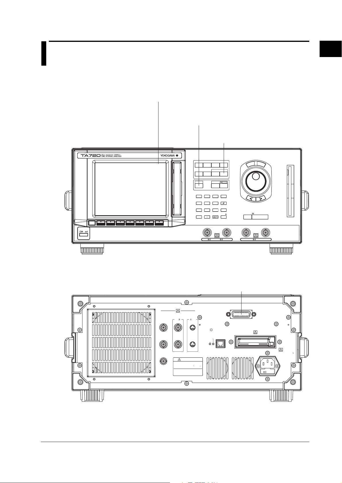
1.1 Names and Functions of the Parts Related to GP-IB Communications
Front Panel
Remote indication appears at the upper right corner of the screen
when in remote mode using communications.
LOCAL key (SHIFT+AUTO SCALE) key
Press this key to clear the remote mode
(controlled via communications) and enter the
local mode in which key operations are enabled.
UTILITY key
Press this key to configure
communications.
S
E
T
L
E
S
S
C
E
T
R
SINGLE START/STOP
EXT ARM/EXT GATE INHIBIT
POWER
SAMPLE
MODE
Remote
ESC
FUNCTION
DISPLAY SCALE
LOCAL
AUTO
SCALE
789
456
123
0
CH
A
INPUT
INITIALIZE
FILE
MARKER UTILITY
COPY MENU
SHIFT
COPY
MHz
m
sec/V/
ENTER
CH
B
n
1
GP-IB Communication Interface
Rear Panel
10MHz REF IN
(1Vp-p)
10MHz OUT
(1Vp-p)
GATE OUT
(TTL)
MONITOR
PROBE
POWER
OUT
( 12V)(50 )
CH
A
1Vp-p
CH
B
WARN ING
Do not operate without reading
safety precautions in user s manual
50
1M
40Vpk
rms
1M
40Vpk5V
GP-IB connector
Connector used to connect the TA720 to
the controller (PC) using a GP-IB cable.
GP-IB(IEEE488)
REFERENCE
ADJUST
ETHERNET
LINK
10BASE - T
TX
100-240V AC
250VA MAX
50/60Hz
FUSE 250V T 3.15A
IM 704510-17E
1-1
Page 7
1.2 Connecting the GP-IB Cable
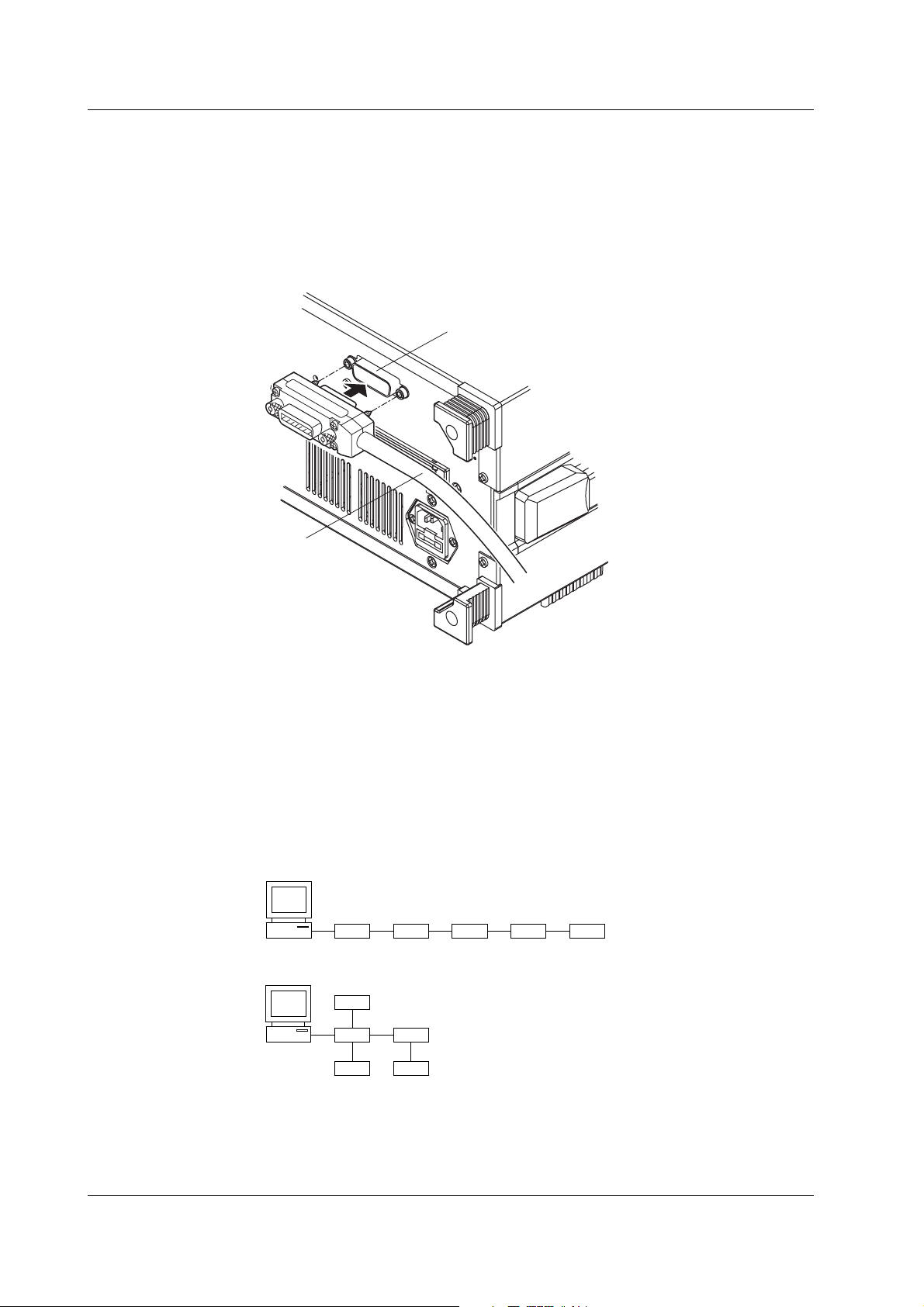
1.2 Connecting the GP-IB Cable
GP-IB Cable
The GP-IB connector used on this instrument is a 24-pin connector that conforms to the
IEEE St’d 488-1978. Use a GP-IB cable that conforms to this standard.
Connection Procedure
Connect the cable as shown below.
GP-IB cable
GP-IB connector
Precautions to Be Taken When Connecting Cables
• Firmly tighten the screws on the GP-IB cable connector.
• Multiple devices can be connected to a single GP-IB system. However, no more than
15 devices (including the controller) can be connected to a single system.
• When connecting multiple devices, each device must have its own unique address.
• Use a cable of length 2 m or less for connecting the devices.
• Make sure the total cable length does not exceed 20 m.
• When communicating, have at least two-thirds of the devices turned ON.
• When connecting multiple devices, connect them in a star or linear configuration (see
the figure below). Loop and parallel configurations are not allowed.
1-2 IM 704510-17E
Page 8

1.3 GP-IB Communication Capabilities and Specifications
1.3 GP-IB Communication Capabilities and Specifications
GP-IB Communication Capabilities
• Listener capability
• All of the information that you can set with the panel keys can be set through the
GP-IB interface except for turning ON/OFF the power and setting the
communication parameters.
• Receives commands from a controller requesting the output of setup information,
measured data, and other information.
• Also receives status report commands.
• Talker capability
Outputs setup information, measured data, and other information.
Note
Listen-only, talk-only, and controller capabilities are not available on this instrument.
Switching between Remote and Local Modes
• When switching from local to remote mode
Receiving a REN (Remote Enable) message from the controller when the instrument
is in the local mode causes the instrument to switch to the remote mode.
• REMOTE indication appears at the upper right corner of the screen (see page 1-1).
• All keys other than the LOCAL (SHIFT+AUTO SCALE) key are locked.
• The settings that existed in the local mode are maintained even when the
instrument switches to the remote mode.
• When switching from remote to local mode
Pressing the LOCAL (SHIFT+AUTO SCALE) key when the instrument is in the
remote mode causes the instrument to switch to the local mode. However, this act is
invalid if the instrument has been set to Local Lockout mode (see page 1-6) by the
controller.
• REMOTE indication at the upper right corner of the screen disappears.
• Key operations are enabled.
• The settings that existed in the remote mode are maintained even when the
instrument switches to the local mode.
1
GP-IB Communication Interface
IM 704510-17E
1-3
Page 9

1.3 GP-IB Communication Capabilities and Specifications
GP-IB Interface Specifications
Electrical and mechanical specifications: Conforms to IEEE St’d 488-1978 (JIS C1901-
Functional specifications: See table below.
Protocol: Conforms to IEEE St’d 488.2-1992
Code: ISO (ASCII) code
Mode: Addressable mode
Address setting: The address can be set in the range from 0 to
Clear remote mode: Clear remote mode by pressing the LOCAL
Function Subset Name Description
Source handshaking SH1 Full source handshaking capability
Acceptor handshaking AH1 Full acceptor handshaking capability
Talker T6 Basic talker capability, serial polling, untalk on
Listener L4 Basic listener capability, unlisten on MTA (My
Service request SR1 Full service request capability
Remote local RL1 Full remote/local capability
Parallel polling PP0 No parallel polling capability
Device clear DC1 Full device clear capability
Device trigger DT1 Full device trigger capability
Controller C0 No controller capability
Electrical characteristics E1 Open collector
1987)
30 on the GP-IB setup menu that is played
using the UTILITY key.
(SHIFT+AUTO SCALE) key. However, key
operations are void when Local Lockout is
enabled by the controller.
MLA (My Listen Address), and no talk-only
capability
Talk Address), and no listen-only capability.
1-4 IM 704510-17E
Page 10
1.4 Settings on the TA720
1.4 Settings on the TA720
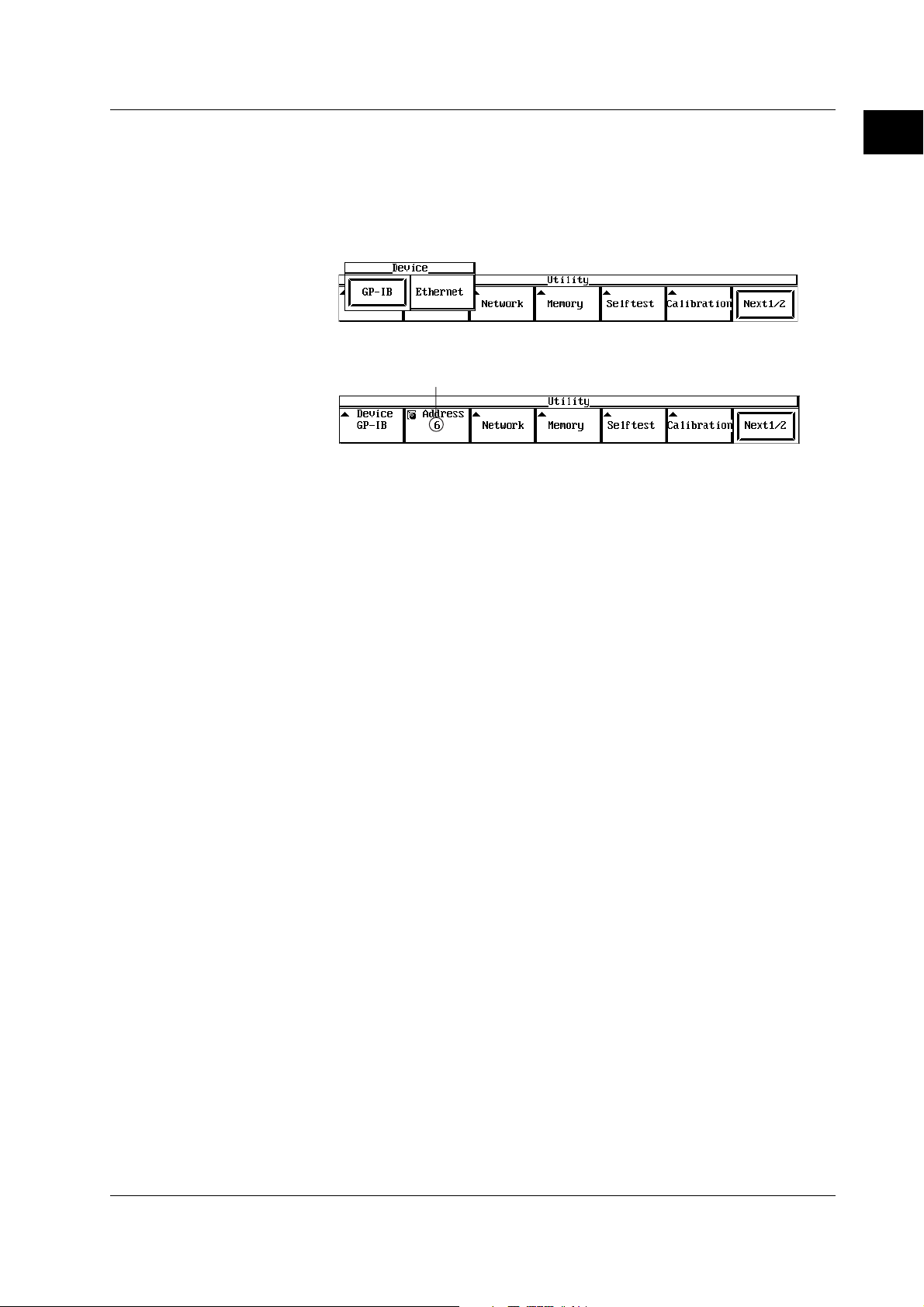
Procedure
1. Press the UTILITY key to display the Utility menu.
2. Press the Device soft key to display the Device selection menu.
3. Select GP-IB using the soft key.
4. Set the address using the rotary knob or numeric keys.
Explanation
Setting the Address
Each device that can be connected via GP-IB has a unique address within the GP-IB
system. This address is used to distinguish the device from others. Therefore, when
you connect the TA720 to a PC, for example, make sure to assign a unique address to
the TA720.
Select the address from the following: The initial value is 1.
Selectable range: 0 to 30
1
GP-IB Communication Interface
Set the address using the rotary knob or numeric keys.
IM 704510-17E
1-5
Page 11

1.5 Responses to Interface Messages
1.5 Responses to Interface Messages
What Is an Interface Message
Interface messages are also referred to as interface commands or bus commands. They
are commands that are issued by the controller. They are classified as follows:
• Uni-line messages
A single control line is used to transmit uni-line messages. The following three types
are available.
IFC (Interface Clear), REN (Remote Enable), and IDY (Identify)
• Multi-line messages
Eight data lines are used to transmit multi-line messages. The messages are
classified as follows:
• Address commands
These commands are valid when the instrument is designated as a listener or as a
talker. The following five types are available.
• Commands that are valid on an instrument that is designated as a listener
GTL (Go To Local), SDC (Selected Device Clear), PPC (Parallel Poll Configure),
and GET (Group Execute Trigger)
• Commands that are valid on an instrument that is designated as a talker
TCT (Take Control)
• Universal commands
These commands are valid on all instruments regardless of the listener and talker
designations. The following five types are available.
LLO (Local Lockout), DCL (Device Clear), PPU (Parallel Poll Unconfigure), SPE
(Serial Poll Enable), and SPD (Serial Poll Disable)
• In addition, listener address, talker address, and secondary commands are also
considered interface messages.
• The differences between SDC and DCL
In multi-line messages, SDC messages are those that require talker or listener
designation and DCL messages are those that do not require the designation.
Therefore, SDC messages are directed at a particular instrument while DCL
messages are directed at all instruments on the bus.
Responses to Interface Messages
• Responses to a uni-line message
• IFC: Clears the talker and listener functions. Stops output if data are being
output.
• REN: Switches between the remote and local modes.
• IDY: Not supported.
• Responses to a multi-line message (address command)
• GTL: Switches to the local mode.
• SDC: Clears the program message (command) being received and the
output queue (see page 5-5).
• GET: Same operation as the *TRG command.
• The COMMunicate:WAIT command is immediately terminated.
• PPC or TCT: Not supported.
• Responses to a multi-line message (universal command)
• LLO: Disables the LOCAL key on the front panel to prohibit switching to the
local mode.
• DCL: Same operation as the SDC message.
• SPE: Sets the talker function on all devices on the bus to serial polling mode.
The controller polls the devices in order.
• SPD: Clears the serial polling mode of the talker function on all devices on the bus.
• PPU: Not supported.
1-6 IM 704510-17E
Page 12
2.1 Names and Functions of the Parts Related to Ethernet Communications
Chapter 2 Ethernet Communication Interface
(Option)
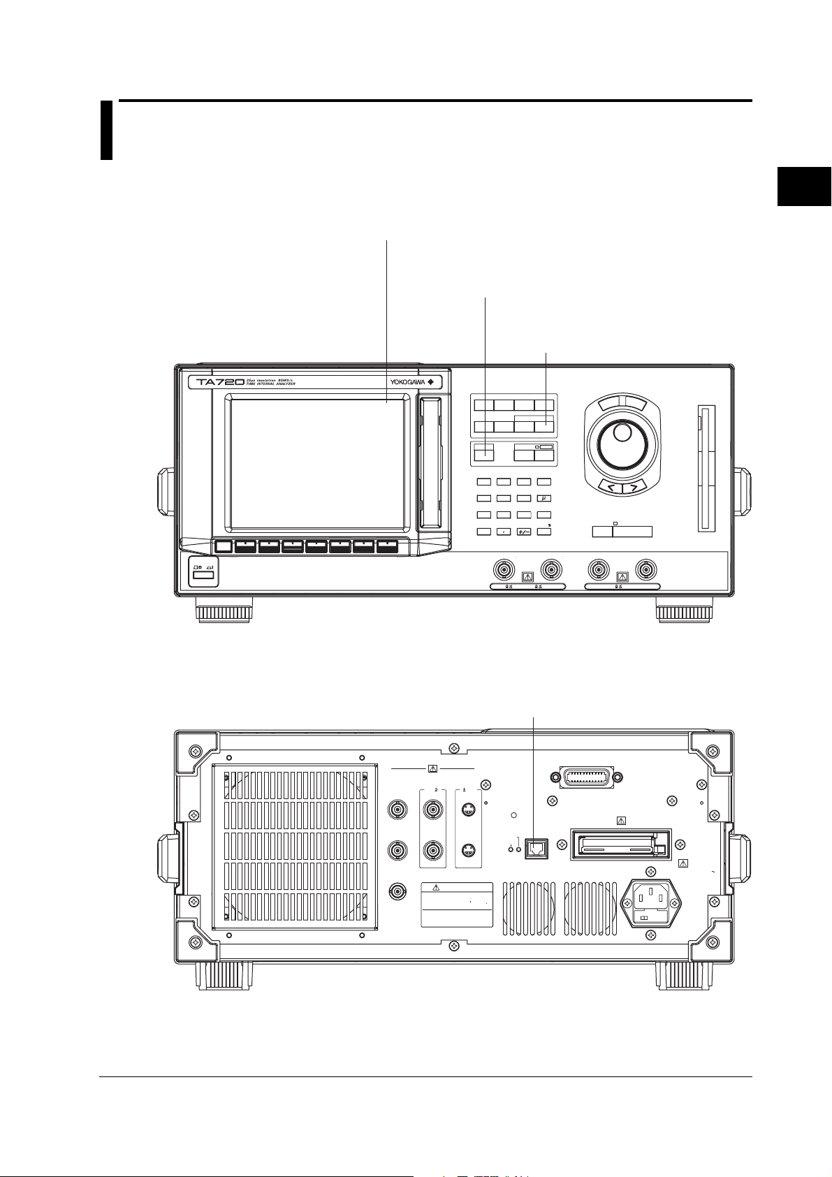
2.1 Names and Functions of the Parts Related to Ethernet Communications
Front Panel
Remote indication appears at the upper right corner of the
screen when in remote mode using communications.
LOCAL key (SHIFT+AUTO SCALE) key
Press this key to clear the remote mode
(controlled via communications) and enter the
local mode in which key operations are enabled.
UTILITY key
Press this key to set the user name
and password for user verification
and TCP/IP parameters.
S
E
T
L
E
S
S
C
E
T
R
SINGLE START/STOP
EXT ARM/EXT GATE INHIBIT
1M
40Vpk5V
POWER
SAMPLE
MODE
Remote
ESC
FUNCTION
DISPLAY SCALE
LOCAL
AUTO
SCALE
789
456
123
0
CH
A
50
INPUT
INITIALIZE
FILE
MARKERUTILITY
COPY MENU
SHIFT
COPY
MHz
m
sec/V/
ENTER
CH
B
1M
rms
n
40Vpk
2
Ethernet Communication Interface (Option)
Rear Panel
10MHz REF IN
(1Vp-p)
10MHz OUT
(1Vp-p)
GATE OUT
(TTL)
Ethernet interface connector
Connector used to connect the TA720 to the
controller (PC) using an Ethernet cable.
For details on how to connect the cable, see page 2-3.
GP-IB(IEEE488)
MONITOR
PROBE
POWER
OUT
( 12V)(50 )
CH
A
1Vp-p
CH
B
WARN ING
Do not operate without reading
safety precautions in user s manual
REFERENCE
ADJUST
LINK
TX
ETHERNET
10BASE - T
100-240V AC
250VA MAX
50/60Hz
FUSE 250V T 3.15A
IM 704510-17E
2-1
Page 13

2.2 Ethernet Communications Functions and Specifications
2.2 Ethernet Communications Functions and Specifications
Reception Function
You can specify the same settings as those specified by front panel key operations.
Receives output requests for measured and computed data, setting parameters of the
panel, and error codes.
Transmission Function
Outputs measured and computed data.
Outputs setting parameters of the panel and the status byte.
Outputs error codes that are generated.
Ethernet Communication Interface Specifications
Number of communication ports: 1
Electrical and mechanical specifications: Conforms to IEEE802.3
Transmission system: 10BASE-T
Maximum transmission rate: 10 Mbps
Connector type: RJ-45
Switching between Remote and Local Modes
• When switching from local to remote mode
If the TA720 receives a “:COMMunicate:REMote ON” command from the PC when it
is in the local mode, it switches to the remote mode.
• REMOTE is displayed at the upper left corner of the screen.
• All keys except the LOCAL (SHIFT+AUTO SCALE) key are disabled.
• The settings that existed in the local mode are maintained even when the
instrument switches to the remote mode.
• When switching from remote to local mode
Pressing the LOCAL (SHIFT+AUTO SCALE) key when the instrument is in the
remote mode causes the instrument to switch to the local mode. However, this is void
when the TA720 has received a “:COMMunicate:LOCKout ON” command from the PC
(local lockout condition).
When the TA720 receives a “:COMMunicate:REMote OFF” command from the PC,
the TA720 switches to the local mode regardless of the local lock condition.
• REMOTE indication at the upper right corner disappears.
• Key operations are enabled.
• The settings that existed in the remote mode are maintained even when the
instrument switches to the local mode.
Note
The Ethernet communication interface cannot be used concurrently with the GP-IB interface.
User Verification Function
When using the Ethernet communication interface, a user name and password are
required when connecting to the network. The user name and password are set on the
User Account pop-up window under the Utility menu of the TA720. For details, see
section 2.4, “Setting the TA720.”
2-2 IM 704510-17E
Page 14
2.3 Connection Using the Ethernet Communication Interface
2.3 Connection Using the Ethernet Communication Interface
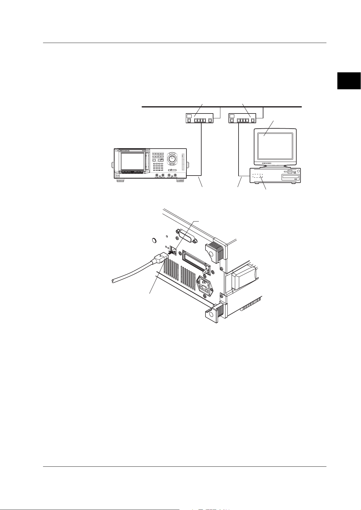
Connection Procedure
Connect a UTP (Unshielded Twisted-Pair) cable or an STP (Shielded Twisted-Pair)
cable that is connected to a hub, for example, to the 10BASE-T port on the rear panel of
the TA720.
Hub or router that supports 10BASE-T
S
E
T
L
E
S
S
C
E
T
R
SAMPLE
MODE
INPUT
FUNCTION
INITIALIZE
FILE
DISPLAY SCALE
MARKER UT I LI TY
LOCAL
COPY MENU
SHIFT
AUTO
COPY
SCALE
n
789
456
m
123
sec/V/
ENTER
SINGLE START/STOP
ESC
POWER
0
CHACH
EXT ARM/EXT GATE INHIBIT
B
501M40Vpk1M40Vpk5V
rms
2
Ethernet Communication Interface (Option)
PC or workstation
UTP cable or STP cable
(Straight cable)
Ethernet port (10BASE-T)
RJ-45 modular jack
Precautions to Be Taken When Connecting Cables
To connect the TA720 and a PC, be sure to use a straight cable via a hub. Operation is
not guaranteed when the TA720 and the PC are connected one-to-one using a cross
cable.
Ethernet NIC
IM 704510-17E
2-3
Page 15
2.4 Setting the TA720
2.4 Setting the TA720
Procedure
• Selecting the Communication Interface
Note
• Setting the User Name, Password, and Timeout
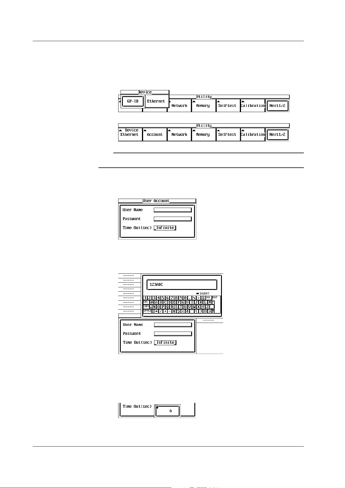
1. Press the UTILITY key to display the Utility menu.
2. Press the Device soft key to display the Device selection menu.
3. Press the Ethernet soft key.
Only the communication interface selected by Device is enabled. The TA720 does not accept
commands that are transmitted using an unselected GP-IB communication interface.
4. Press the Account soft key.
The user verification dialog box opens.
5. Turn the rotary knob to move the cursor onto the User Name.
6. Press the SELECT key to display the keyboard.
7. Enter the user name. Specify anonymous if you wish to allow access to all
users. To restrict access, enter the user name using up to 15 characters.
8. Turn the rotary knob to move the cursor to Password.
9. Press the SELECT key to display the keyboard.
10. Enter the password using up to 15 characters.
11. Turn the rotary knob to move the cursor onto the Time Out.
12. Press the SELECT key.
13. Set the timeout time using the rotary knob or numeric keys.
14. Press the SELECT key to confirm the new settings.
2-4 IM 704510-17E
Page 16

Explanation
2.4 Setting the TA720
Note
• For details on the keyboard operation, see section 4.4, “Entering Values and Character
Strings” in the
• User name and password are case-sensitive.
• Setting the TCP/IP
To use the network interface function, the following TCP/IP settings must be entered.
• IP address
• Subnet mask
• Default gateway
For details on how to enter these parameters, see section 12.2, “Setting the TCP/IP”
in the
TA720 User’s Manual IM704510-01E
Enter the following settings when using a controller to set information that can be
specified through key operation on the TA720 or when outputting setting parameters or
output waveform data to the controller.
• Setting the User Name and Password
The network interface has a user verification function. A user name and password for
the TA720 are set in advance.
• Setting the User Name
Enter the password using up to 15 characters. The default setting is “anonymous.”
TA720 User’s Manual IM704510-01E
.
.
2
Ethernet Communication Interface (Option)
• Setting the password
Enter the password using up to 15 characters.
• Setting the Timeout Time
The connection to the TA720 is automatically dropped if there is no access to the
TA720 for the specified time. The default setting is Infinite (no timeout).
• Setting the TCP/IP
For details, see section 12.2, “Setting the TCP/IP” in the
IM704510-01E
.
TA720 User’s Manual
Note
• If the user verification fails, connection to the TA720 is dropped.
• Password is not required if the user name is “anonymous.”
• If you change the user name, password, timeout time, or TCP/IP settings, power-cycle the
TA720 to activate the new settings.
IM 704510-17E
2-5
Page 17

Chapter 3 Program Syntax and Programming
,
<Program header>
<Program data>Space
3.1 Messages
3.1 Messages
Message
Messages are used to exchange information between
the controller and the instrument. Messages that are
sent from the controller to the instrument are called
program messages and messages that are sent back
from the instrument to the controller are called
response messages.
If a program message contains a message unit that
requests a response (a query), the instrument returns
a response message upon receiving the program
message. A single response message is always
returned in response to a single program message.
Program Message
Data that is sent from the controller to the instrument
are called program messages. The program message
format is shown below.
;
<Program message unit>
<Program Message Unit>
A program message consists of one or more program
message units; each unit corresponds to one
command. The instrument executes the received
commands in order.
Each program message unit is separated by a
semicolon (;).
For details regarding the format of the program
message unit, see the next section.
<PMT>
<PMT>
PMT is a program message terminator. The following
three types are available.
NL (New Line): Same as LF (Line Feed). ASCII
code “0AH”
^END: END message that is defined in
IEEE488.1 (EOI signal)
(The data byte that is sent
simultaneously with the END
message is the last data of the
program message.)
NL^END: NL with an END message added
(NL is not included in the program
message.)
• Program Message Unit Format
The program message unit format is shown below.
<Program header>
The program header indicates the command type. For
details, see page 3-3.
<Program Data>
If certain conditions are required in executing a
command, program data is added. A space (ASCII
code “20H”) separates the program data from the
header. If there are multiple sets of program data, they
are separated by commas (,).
For details, see page 3-5.
3
Program Syntax and Programming
Example
:MEASURE:MODE HHISTOGRAM;FUNCTION PERIOD,A<PMT>
Unit Unit
Example
:SAMPLE:GATE:MODE EVENT<PMT>
Header
Data
3-1IM 704510-17E
Page 18

3.1 Messages
Response Message
Data that is sent from the instrument to the controller
are called response messages. The response
message format is shown below.
;
<Response message unit>
<RMT>
<Response Message Unit>
A response message consists of one or more
response message units; each response message unit
corresponds to one response.
Response message units are separated by a
semicolon (;).
For details regarding the format of the response
message unit, see page 3-4.
Example
:SAMPLE:GATE:MODE EXTERNAL;POLARITY POSITIVE<RMT>
Unit Unit
<RMT>
A response message terminator. It is NL^END.
• Response Message Unit Format
The response message unit format is shown below.
,
<Response header> <Response data>Space
<Response Header>
A response header sometimes precedes the response
data. A space separates the data from the header.
For details, see page 3-4.
<Response Data>
Response data contains the content of the response.
If there are multiple sets of response data, they are
separated by commas (,). For details, see page 3-5.
Example
500.0E-03<RMT> :SAMPLE:INTERVAL MINIMUM<RMT>
Data Header Data
If there are multiple queries in a program message,
responses are made in the same order as the queries.
In most cases, a single query returns a single
response message unit, but there are a few queries
that return multiple units. The first response message
unit always corresponds to the first query, but the nth
response unit may not necessarily correspond to the
nth query. Therefore, if you want to make sure that
every response is retrieved, divide the program
messages into individual messages.
Precautions to Be Taken when Transferring
Messages
• If a program message that does not contain a query
is sent, the next program message can be sent at
any time.
• If a program message that contains a query is sent,
a response message must be received before the
next program message can be sent. If the next
program message is sent before the response
message is received in its entirety, an error occurs.
The response message that was not received is
discarded.
• If the controller tries to receive a response message
when there is none, an error occurs. If the
controller tries to receive a response message
before the transmission of the program message is
complete, an error occurs.
• If a program message containing multiple message
units is sent, and the message contains incomplete
units, the instrument will attempt to execute the
ones that are believed to be complete. However,
these attempts may not always be successful. In
addition, if the message contains queries, the
responses may not be returned.
Deadlock
The instrument can store in its buffer program and
response messages of length 1024 bytes or more (The
number of available bytes varies depending on the
operating conditions). When both the transmit and
receive buffers become full at the same time, the
instrument can no longer continue to operate. This
state is called a deadlock. In this case, operation can
be resumed by discarding the program message.
Deadlock will not occur if the program message
(including the <PMT>) is kept below 1024 bytes.
Furthermore, deadlock never occurs if a program
message does not contain a query.
3-2 IM 704510-17E
Page 19

3.2 Commands
3.2 Commands
Command
There are three types of commands (program headers)
that are sent from the controller to the instrument.
They differ in their program header formats.
Common Command Header
Commands that are defined in the IEEE 488.2-1992
are called common commands. The header format of
a common command is shown below. An asterisk (*)
is always placed in the beginning of a command.
<Mnemonic>
*
An example of a common command: *CLS
Compound Header
Dedicated commands used by the instrument are
classified and arranged in a hierarchy according to
their functions. The format of a compound header is
shown below. A colon (:) must be used to specify a
lower hierarchy.
:
<Mnemonic>
An example of a compound header:
MEASURE:FUNCTION
?
:
?
When Concatenating Commands
• Command Group
A command group is a group of commands that
have common compound headers arranged in a
hierarchy. A command group may contain subgroups.
Example Group of commands related to sampling
:SAMPLE?
:SAMPLE:GATE?
:SAMPLE:GATE:MODE
:SAMPLE:GATE:EVENTSIZE
:SAMPLE:GATE:POLARITY
:SAMPLE:GATE:TIME
:SAMPLE:INTERVAL
:SAMPLE:ARMING:SOURCE
:SAMPLE:ARMING:DELAY:MODE
:SAMPLE:ARMING:DELAY:TIME
• When Concatenating Commands of the Same
Group
The instrument stores the hierarchical level of the
command that is currently being executed, and
performs analysis on the assumption that the next
command sent will also belong to the same level.
Therefore, common header sections can be omitted
for commands belonging to the same group.
Example :INPUT:ACHANNEL:COUPLING AC;
IMPEDANCE I50<PMT>
3
Program Syntax and Programming
Simple Header
These commands are functionally independent and do
not have a hierarchy. The format of a simple header is
shown below.
:
<Mnemonic>
?
An example of a simple header: START
Note
A <mnemonic> is a character string made up of alphanumeric
characters.
• When Concatenating Commands of Different
Groups
If the following command does not belong to the
same group, a colon (:) is placed in front of the
header.
Example :MEASURE:MODE TSTAMP;:DISPLAY:
ITEM LIST<PMT>
• When Concatenating Simple Headers
If a simple header follows another command, a
colon (:) is placed in front of the simple header.
Example :MEASURE:MODE TSTAMP;:
START<PMT>
• When Concatenating Common Commands
Common commands that are defined in the IEEE
488.2-1992 are independent of hierarchy. Colons
(:) are not needed before a common command.
Example :MEASURE:MODE TSTAMP;*CLS;
FUNCTION PERIOD,A<PMT>
3-3IM 704510-17E
Page 20

3.2 Commands/3.3 Responses
• When Separating Commands with <PMT>
If a terminator is used to separate two commands,
each command is a separate message. Therefore,
the common header must be specified for each
command even when commands belonging to the
same command group are being concatenated.
Example :MEASURE:MODE TSTAMP<PMT>:
MEASURE:FUNCTION PERIOD,A<PMT>
Upper-level Query
An upper-level query is a query in which a question
mark (?) is appended to the highest level command of
a group. Execution of an upper-level query allows all
settings that can be specified in the group to be
received at once. Some query groups which are
comprised of more than three hierarchical levels can
output all the lower level settings.
Example :MEASURE?<PMT> -> :MEASURE:
MODE HHISTOGRAM;
FUNCTION PERIOD,A;SLOPE RISE
The response to an upper-level query can be
transmitted as a program message back to the
instrument. In this way, the settings that existed when
the upper-level query was made can be restored.
However, some upper-level queries will not return setup
information that is not currently in use. It is important to
remember that not all the group’s information is
necessarily returned as part of a response.
Header Interpretation Rules
The instrument interprets the header that is received
according to the rules below.
• Mnemonics are not case sensitive.
Example MEASure can be also written as
measure or Measure.
• The lower-case section of the header can be omitted.
Example MEASure can also be written as MEASU
or MEAS
• The question mark (?) at the end of a header
indicates that it is a query. The question mark (?)
cannot be omitted.
Example The shortest abbreviation for
“MEASure?” is “MEAS?.”
• If the <x> (value) at the end of a mnemonic is
omitted, it is interpreted as a 1.
Example If WINDow<x> is written as WIND, this
represents WINDow1.
• The section enclosed by braces ([]) can be omitted.
Example :CALCulation[:WINDow1]:
AVERage? can be written as
:CALCulation:AVERage?.
However, the last section enclosed by braces ([])
cannot be omitted in an upper-level query.
3.3 Responses
When the controller sends a message unit that has a
question mark (?) in its program header (query), the
instrument returns a response message to the query.
A response message is returned in one of the following
two forms.
• Response consisting of a header and data
If the response can be used as a program message
without any change, it is returned with a command
header attached.
Example :SAMPLE:GATE:MODE?<PMT> ->
:SAMPLE:GATE:MODE EVENT<RMT>
• Response consisting of data only
If the response cannot be used as a program
message unless changes are made to it (query-only
command), only the data section is returned.
However, there are query-only commands that
return responses with the header attached.
Example :STATUS:ERROR?<PMT> ->
0,”NO ERROR”<RMT>
• When You Wish to Return a Response without a
Header
Responses that return both header and data can be
set so that only the data section is returned. The
“:COMMunicate:HEADer” command is used to do
this.
• Abbreviated Form
Normally, the lower-case section is removed from a
response header before the response is returned to
the controller. Naturally, the full form of the header
can also be used. For this, the
“:COMMunicate:VERBose” command is used.
3-4 IM 704510-17E
Page 21

3.4 Data
3.4 Data
Data
A data section comes after the header. A space must
be included between the header and the data. The
data contains conditions and values. Data is classified
as below.
Data Description
<Decimal> Value expressed as a decimal number
(Example: The number of measurement
samples
-> :SAMPle:GATE:EVENtsize 100)
<Voltage><Time> Physical value
<Frequency> (Example: Gate time
<Percentage> -> :SAMPle:GATE:TIME 1US)
<Register> Register value expressed as either binary,
octal, decimal or hexadecimal.
(Example: Extended event register value
-> :STATUS:EESE #HFE)
<Character data> Predefined character string (mnemonic).
Can be selected from { }
(Example: Gate mode selection ->
:SAMPle:GATE:MODE {EVENt|TIME|
EXTernal})
<Boolean> Indicates ON and OFF. Set to ON, OFF or
value
(Example: Turn ON panorama display
-> :DISPlay:PANorama:STATe ON)
<Character string data> Arbitrary character string
(Example: Name of the file to be deleted
-> :FILE:DELete:SETup “SETUP_1”)
<Block data> Arbitrary 8-bit data
(Example: Response to acquired measured
data -> #6000010ABCDEFGHIJ)
<Decimal>
<Decimal> indicates a value expressed as a decimal
number, as shown in the table below. Decimal values are
given in the NR form as specified in the ANSI X3.42-1975.
Symbol Description Example
<NR1> Integer 125 -1 +1000
<NR2> Fixed-point number 125.0 -.90 +001.
<NR3> Floating-point number 125.0E+0 -9E-1 +.1E4
<NRf> Any of the forms <NR1> to <NR3> is allowed.
• The instrument can receive decimal values that are
sent from the controller in any of the forms, <NR1>
to <NR3>. This is represented by <NRf>.
• For response messages that the instrument returns
to the controller, the form (<NR1> to <NR3> to be
used) is determined by the query. The same form is
used regardless of the size of the value.
• In the case of <NR3>, the “+” after the “E” can be
omitted, but the “–” cannot.
• If a value outside the setting range is entered, the
value will be normalized so that it is just inside the
range.
• If a value has more significant digits than the
available resolution, the value is rounded.
<Voltage>, <Time>, <Frequency>, <Percent>
<Voltage>, <Time>, <Frequency>, and <Percent>
indicate decimal values that have physical significance.
Except for <Percent>, a <Multiplier> or <Unit> can be
attached to <NRf>. They can be entered in any of the
following forms.
Form Example
<NRf><Multiplier><Unit> 5MV
<NRf><Unit> 5E-3V
<NRf><Multiplier> 5M
<NRf> 5E-3
•<Multiplier>
Multipliers which can be used are shown below.
Symbol Word Multiplier
EX Exa 10
PE Peta 10
T Tera 10
G Giga 10
MA Mega 10
K Kilo 10
MMilli 10
U Micro 10
N Nano 10
PPico 10
F Femto 10
A Ato 10
18
15
12
9
6
3
–3
–6
–9
–12
–15
–18
• <Unit>
Units which can be used are shown below.
Symbol Word Description
V Volt Voltage
S Second Time
HZ Hertz Frequency
MHZ Megahertz Frequency
PCT Percentage Percentage
• <Multiplier> and <Unit> are not case sensitive.
• “U” should be used in place of “µ” in the data.
• “MA” is used for Mega to distinguish it from Milli.
• If both <Multiplier> and <Unit> are omitted, the
default unit is used.
• Response messages are always expressed in the
<NR3> form. Response messages are returned
using the default unit without the <Multiplier> or
<Unit>.
3
Program Syntax and Programming
3-5IM 704510-17E
Page 22

3.4 Data
<Register>
<Register> indicates an integer, and can be expressed
in hexadecimal, octal, or binary as well as a decimal
number. <Register> is used when each bit of the
value has a particular meaning. <Register> is
expressed in one of the following forms.
Form Example
<NRf> 1
#H #H0F
<Hexadecimal value made up of the digits 0 to 9 and A to F>
#Q<Octal value made up of the digits 0 to 7> #q777
#B<Binary value made up of the digits 0 and 1> #B001100
• <Register> is not case sensitive.
• Response messages are always expressed as
<NR1>.
<Character data>
<Character Data> is a specified string of character
data (a mnemonic). It is mainly used to indicate
options and is chosen from the character strings given
in { }. For interpretation rules, refer to “Header
Interpretation Rules” on page 3-4.
<Character String Data>
<Character string data> is not a specified character
string like <Character data>. It is an arbitrary
character string. The character string must be
enclosed in single quotation marks (‘) or double
quotation marks (“).
Form Example
<Character string data> ‘ABC’ “IEEE488.2-1987”
• If a character string contains a double quotation
mark (“), the double quotation mark will be replaced
by two concatenated double quotation marks (“”).
This rule also applies to a single quotation mark
within a character string.
•A response message is always enclosed in double
quotation marks (“).
• <Character string data> is an arbitrary character
string, therefore this instrument assumes that the
remaining program message units are part of the
character string if no single (‘) or double quotation
mark (“) is encountered. As a result, no error will
be detected if a quotation mark is omitted.
Form Example
{EVENt|TIME|EXTernal} EVENt
• As with the header, the “COMMunicate:VERBose”
command can be used to select whether to return
the response in the full form or in the abbreviated
form.
• The “COMMunicate:HEADer” setting does not
affect the <character data>.
<Boolean>
<Boolean> is data which indicates ON or OFF, and is
expressed in one of the following forms.
Form Example
{ON|OFF|<NRf>} ON OFF 1 0
• When <Boolean> is expressed in the <NRf> form,
“OFF” is selected if the rounded integer value is “0,”
and ON for all other cases.
•A response message is always returned with a “1” if
the value is ON and “0” if the value is OFF.
<Block Data>
<Block data> is arbitrary 8-bit data. It is only used in
response messages on the TA720 and is expressed in
the following form.
Form Example
#8<8-digit decimal number> #800000010ABCDEFGHIJ
<data byte sequence>
•#8
Indicates that the data is <Block data>.
• <8-digit decimal number>
Indicates the number of bytes of data (example:
00000010 = 10 bytes).
• <data byte sequence>
Expresses the actual data (example:
ABCDEFGHIJ).
• Data is comprised of 8-bit values (0 to 255). This
means that the ASCII code “0AH,” which stands for
“NL,” can also be a code used for data. Hence,
care must be taken when programming the
controller.
3-6 IM 704510-17E
Page 23

3.5 Synchronization with the Controller
3.5 Synchronization with the
Controller
The TA720 does not support overlap commands,
which allows the execution of the next command to
start before the execution of the previous command is
completed. If multiple sequential commands are sent
consecutively, the execution of the next command is
held until the execution of the previous command is
completed.
Achieving Synchronization
Synchronization is sometimes required for reasons
other than communications-related reasons, such as
the activation of a trigger, even if a sequential
command is used.
For example, if a “next program” message is
transmitted to make an inquiry about the waveform
data which has been acquired using single mode as
the trigger mode, the “MEMory:SEND?” command is
sometimes executed whether acquisition has been
completed or not, causing a command execution error.
:SSTart;:MEMory:SEND?<PMT>
In this case, the following method must be used to
synchronize with the end of the acquisition.
• Using the STATus:CONDition? query
The “STATus:CONDition?” query is used to query
the contents of the condition register (page 5-4). It
is possible to judge whether acquisition is in
progress or not by reading bit 0 of the condition
register. Bit 0 is “1” if acquisition is in progress, and
“0” if acquisition is stopped.
Example :SSTart<PMT>
:STATus:CONDition?<PMT>
(Read the response. If bit 0 is 0, repeat
this command until it becomes 1.)
:MEMory:SEND?<PMT>
The :MEMory:SEND? command will not be
executed until bit 0 of the condition register is set to
“1.”
• Using the extended event register
The changes in the condition register can be
reflected in the extended event register (page 5-4).
Example :STATus:FILTer1 RISE;:STATus:
EESE 1;EESR?;*SRE8;SSTart<PMT>
(Wait for a service request occurrence)
:MEMory:SEND?<PMT>
The “STATus:FILTer1 RISE” command sets the
transition filter so that bit 0 (FILTer1) of the
extended event register is set to “1” when bit 0 of
the condition register changes from “0” to “1.”
The “:STATus:EESE 1” command is used to
reflect only bit 0 of the extended event register to
the status byte.
The “STATus:EESR?” command is used to clear
the extended event register.
The “*SRE” command is used to generate a service
request solely on the cause of the extended event
register.
The “:MEMory:SEND?” command will not be
executed until a service request is generated.
• Using the COMMunicate:WAIT command
The “COMMunicate:WAIT” command halts
communications until a specific event is generated.
Example :STATus:FILTer1 RISE;:STATus:
EESR?;:SSTart<PMT>
(Read the response to STATus:EESR?)
:COMMunicate:WAIT 1;:MEMory:
SEND?<PMT>
For a description of “STATus:FILTer1 RISE” and
“STATus:EESR?” see the previous section
regarding the extended event register.
The “COMMunicate:WAIT 1” command indicates
that the program will wait for bit 0 of the extended
event register to be set to “1.”
The :MEMory:SEND? command will not be
executed until bit 0 of the extended event register is
set to “1.”
3
Program Syntax and Programming
3-7IM 704510-17E
Page 24

4.1 List of Commands
Chapter 4 Commands
4.1 List of Commands
Command Function Page
ASCale Group
:ASCale Executes auto scaling. 4-8
CALCulation Group
:CALCulation? Queries all settings related to the statistical value. 4-10
:CALCulation:AREA Queries the computation range or queries the current setting. 4-10
:CALCulation[:MEAS<x>]:AUTot? Queries auto window T. 4-11
:CALCulation[:MEAS<x>][:{BLOCk<x>|BALL}]:TAVerage?
Queries the average value when using time variation. 4-11
:CALCulation[:MEAS<x>][:{BLOCk<x>|BALL}]:TFLutter?
Queries the σ/AVE value (flutter) when using time variation. 4-11
:CALCulation[:MEAS<x>][:{BLOCk<x>|BALL}]:TJITter?
Queries the P-P/AVE value (jitter) when using time variation. 4-12
:CALCulation[:MEAS<x>][:{BLOCk<x>|BALL}]:TMAXimum?
Queries the maximum value when using time variation. 4-12
:CALCulation[:MEAS<x>][:{BLOCk<x>|BALL}]:TMINimum?
Queries the minimum value when using time variation. 4-13
:CALCulation[:MEAS<x>][:{BLOCk<x>|BALL}]:TPTopeak?
Queries the P-P value when using time variation. 4-13
:CALCulation[:MEAS<x>][:{BLOCk<x>|BALL}]:TRF?
Queries the RF value when using time variation. 4-14
:CALCulation[:MEAS<x>][:{BLOCk<x>|BALL}]:TSDeviation?
Queries the standard deviation (σ) when using time variation. 4-14
:CALCulation[:MEAS<x>][:{BLOCk<x>|BALL}]:TSNumber?
Queries the number of samples for the statistical computation when using
time variation. 4-15
:CALCulation[:MEAS<x>]:CONStt Sets constant T or queries the current setting. 4-15
:CALCulation[:MEAS<x>][:WINDow<x>]:AVERage?
Queries the average value when using histogram. 4-16
:CALCulation[:MEAS<x>][:WINDow<x>]:DEViation?
Queries the deviation when using histogram. 4-16
:CALCulation[:MEAS<x>][:WINDow<x>]:DEVT?
Queries the deviation/T value when using histogram. 4-17
:CALCulation[:MEAS<x>][:WINDow<x>]:FLUTter?
Queries the σ/AVE value (flutter) when using histogram. 4-17
:CALCulation[:MEAS<x>][:{WINDow<x>|SUMMation}]]:JITTer?
Queries the σ/T value (jitter) when using histogram. 4-18
:CALCulation[:MEAS<x>][:WINDow<x>]:MAXimum?
Queries the maximum value when using histogram. 4-18
:CALCulation[:MEAS<x>][:WINDow<x>]:MEDian?
Queries the median value when using histogram. 4-19
:CALCulation[:MEAS<x>][:WINDow<x>]:MINimum?
Queries the minimum value when using histogram. 4-19
:CALCulation[:MEAS<x>][:WINDow<x>]:MODE?
Queries the most frequent value when using histogram. 4-20
:CALCulation[:MEAS<x>][:{WINDow<x>|SUMMation}]:PTOPeak?
Queries the P-P value when using histogram. 4-20
:CALCulation[:MEAS<x>][:{WINDow<x>|SUMMation}]:SDEViation?
Queries the standard deviation (σ) when using histogram. 4-21
:CALCulation[:MEAS<x>][:{WINDow<x>|SUMMation}]:SNUMber?
Queries the number of samples for the statistical computation when
using histogram. 4-21
:CALCulation:PARameter? Queries whether all the statistical computations are turn ON or OFF. 4-22
:CALCulation:PARameter:CLEar Turns OFF all the statistical computation values. 4-22
:CALCulation:PARameter:AVERage Turns ON/OFF the average computation when using histogram or
queries the current setting. 4-22
:CALCulation:PARameter:DEViation Turns ON/OFF the deviation computation when using histogram or queries
the current setting. 4-22
:CALCulation:PARameter:DEVT Turns ON/OFF the deviation/T computation when using histogram or
queries the current setting. 4-22
4
Command
4-1IM 704510-17E
Page 25

4.1 List of Commands
Command Function Page
:CALCulation:PARameter:FLUTter Turns ON/OFF the σ/AVE (flutter) computation when using histogram or
:CALCulation:PARameter:JITTer Turns ON/OFF the σ/T (jitter) computation when using histogram or
:CALCulation:PARameter:MAXimum Turns ON/OFF the maximum value computation when using histogram or
:CALCulation:PARameter:MEDian Turns ON/OFF the median value computation when using histogram or
:CALCulation:PARameter:MINimum Turns ON/OFF the minimum value computation when using histogram or
:CALCulation:PARameter:MODE Turns ON/OFF the most frequent value computation when using histogram
:CALCulation:PARameter:PTOPeak Turns ON/OFF the P-P value computation when using histogram or queries
:CALCulation:PARameter:SDEViation
:CALCulation:PARameter:TAVerage Turns ON/OFF the average computation when using time variation or
:CALCulation:PARameter:TFLutter Turns ON/OFF the σ/AVE (flutter) computation when using time variation
:CALCulation:PARameter:TJITter Turns ON/OFF the P-P/AVE (jitter) computation when using time variation or
:CALCulation:PARameter:TMAXimum Turns ON/OFF the maximum value computation when using time variation or
:CALCulation:PARameter:TMINimum Turns ON/OFF the minimum value computation when using time variation or
:CALCulation:PARameter:TPTopeak Turns ON/OFF the P-P value computation when using time variation or
:CALCulation:PARameter:TRF Turns ON/OFF the RF value computation when using time variation or
:CALCulation:PARameter:TSDeviation
:CALCulation:POLarity Sets the polarity to be analyzed when measuring both pulse widths or both
COMMunicate Group
:COMMunicate? Queries all settings related to communications. 4-25
:COMMunicate:HEADer Sets whether to attach a header to the response data or queries the current
:COMMunicate:LOCKout Sets or clears local lockout. 4-25
:COMMunicate:REMote Switches between remote and local. 4-25
:COMMunicate:VERBose Sets whether to use abbreviated or unabbreviated form for response data. 4-25
:COMMunicate:WAIT Waits for an extended event to occur. 4-26
:COMMunicate:WAIT? Creates a response for the specified extended event. 4-26
DISPlay Group
:DISPlay? Queries all settings related to the display. 4-28
:DISPlay:BGRaph Turns ON/OFF the BOTH Graph display when measuring both pulse widths
:DISPlay:BLOCk Sets the displayed block or queries the current setting. 4-28
:DISPlay:DOTConnect Turns ON/OFF dot connect on the time variation display or queries the
:DISPlay:DOTType Sets the display method of the measured point on the time variation display
:DISPlay:GRAPhsize Sets the size of the graph display or queries the current setting. 4-29
:DISPlay:GRID Turns ON/OFF the grid display on the time variation display or queries the
:DISPlay:ITEM Sets the display format or queries the current setting. 4-29
:DISPlay:OVERlap Sets whether to display waveforms overlapped (ON/OFF) or queries the
:DISPlay:PANorama[:STATe] Turns ON/OFF the panorama display or queries the current setting. 4-29
:DISPlay:SGRaph Sets the display at the bottom section of the screen when using ALL display
:DISPlay:SITem Sets the type of statistical values to be displayed on the statistical display or
queries the current setting. 4-22
queries the current setting. 4-22
queries the current setting. 4-22
queries the current setting. 4-22
queries the current setting. 4-22
or queries the current setting. 4-23
the current setting. 4-23
Turns ON/OFF the standard deviation (σ) computation when using
histogram or queries the current setting. 4-23
queries the current setting. 4-23
or queries the current setting. 4-23
queries the current setting. 4-23
queries the current setting. 4-23
queries the current setting. 4-23
queries the current setting. 4-24
queries the current setting. 4-24
Turns ON/OFF the standard deviation (σ) computation when using time
variation or queries the current setting. 4-24
edges or queries the current setting. 4-24
setting. 4-25
or both edges or queries the current setting. 4-28
current setting. 4-28
or queries the current setting. 4-28
current setting. 4-29
current setting. 4-29
on the multi window or auto window or queries the current setting. 4-29
queries the current setting. 4-30
4-2 IM 704510-17E
Page 26

4.1 List of Commands
Command Function Page
:DISPlay:SSTYle Sets the display format on the statistical display or queries the current
setting. 4-30
:DISPlay:STATistic Turns ON/OFF the statistical display when using histogram or time variation
display or queries the current setting. 4-30
:DISPlay:WINDow Sets the window to be displayed or queries the current setting. 4-30
FILE Group
:FILE? Queries all settings related to files. 4-31
:FILE:CDIRectroy Changes the current directory. 4-31
:FILE:DELete:{BINary|BMP|POSTscript|SETup|STATistic|TIFF|TEXT}
Deletes various types of files. 4-32
:FILE:DRIVe Sets the target drive. 4-32
:FILE:FORMat Executes the floppy disk format. 4-32
:FILE:FREE? Queries the free disk space in bytes. 4-32
:FILE:LOAD:{BINary|SETup} Recalls various types of files. 4-32
:FILE:MDIRectory Creates a directory. 4-32
:FILE:PATH? Queries the current directory. 4-32
:FILE:SAVE? Queries all settings related to file saving. 4-32
:FILE:SAVE:ANAMing Turns ON/OFF the auto naming function of saved file names or queries the
current setting. 4-32
:FILE:SAVE:{BINary|SETup|STATistic|TEXT}
Saves various types of files. 4-33
:FILE:SAVE:COMMent Sets the comment at the top left section of the screen or queries the current
setting. 4-33
:FILE:SAVE:SITem Sets the type of statistical data file to be saved or queries the current setting. 4-33
HCOPy Group
:HCOPy? Queries all settings related to the output of screen image data. 4-34
:HCOPy:ABORt Aborts the printout of the screen image. 4-34
:HCOPy:ANAMing Turns ON/OFF the auto naming function of file names when saving screen
images to files or queries the current setting. 4-35
:HCOPy:CDIRectory Changes the current directory. 4-35
:HCOPy:COMMent Sets the comment at the top left section of the screen or queries the current
setting. 4-35
:HCOPy:COMPression Turns ON/OFF the compression when saving the screen image in BMP
format or queries the current setting. 4-35
:HCOPy:DEVice Sets the output destination of the screen image or queries the current setting. 4-35
:HCOPy:DRIVe Sets the target drive. 4-35
:HCOPy[:EXECute] Executes the printout of the screen image. 4-35
:HCOPy:FILename Sets the name of the file for saving the screen image or queries the current
setting. 4-35
:HCOPy:FORMat Sets the format for saving the screen image or queries the current setting. 4-35
:HCOPy:TONE Sets the color/gradation for saving the screen image or queries the current
setting. 4-35
HHIStogram and THIStogram Group
:{HHIStogram<x>|THIStogram<x>}? Queries all settings related to the histogram display. 4-38
:{HHIStogram<x>|THIStogram<x>}:AUTO?
Queries all settings related to the auto window. 4-38
:{HHIStogram<x>|THIStogram<x>}:AUTO:MODulation
Sets the modulation type on the auto window or queries the current setting. 4-38
:{HHIStogram<x>|THIStogram<x>}:AUTO:TTYPe
Sets how to determine constant T on the auto window or queries the current
setting. 4-38
:{HHIStogram<x>|THIStogram<x>}:AUTO:WINDow1:STATe
Turns ON/OFF window 1 on the auto window or queries the current setting. 4-38
:{HHIStogram<x>|THIStogram<x>}:MARKer?
Queries all settings related to the marker. 4-38
:{HHIStogram<x>|THIStogram<x>}:MARKer:LOW
Sets the low marker value or queries the current setting. 4-38
:{HHIStogram<x>|THIStogram<x>}:MARKer[:STATe]
Turns ON/OFF the marker or queries the current setting. 4-39
:{HHIStogram<x>|THIStogram<x>}[:MODE]
Sets the window mode or queries the current setting. 4-39
:{HHIStogram<x>|THIStogram<x>}:MULTi?
Queries all settings related to the multi window. 4-39
:{HHIStogram<x>|THIStogram<x>}:MULTi:FREQuency
Sets constant T using the frequency format or queries the current setting. 4-39
4
Command
4-3IM 704510-17E
Page 27

4.1 List of Commands
Command Function Page
:{HHIStogram<x>|THIStogram<x>}:MULTi:OFFSet
:{HHIStogram<x>|THIStogram<x>}:MULTi:SIZE
:{HHIStogram<x>|THIStogram<x>}:MULTi:TVALue
:{HHIStogram<x>|THIStogram<x>}:MULTi:UPDate
:{HHIStogram<x>|THIStogram<x>}:MULTi:WINDow<x>?
:{HHIStogram<x>|THIStogram<x>}:MULTi:WINDow<x>:HORizontal?
:{HHIStogram<x>|THIStogram<x>}:MULTi:WINDow<x>:HORizontal:CENTer
:{HHIStogram<x>|THIStogram<x>}:MULTi:WINDow<x>:HORizontal:SPAN
:{HHIStogram<x>|THIStogram<x>}:MULTi:WINDow<x>:LABel
:{HHIStogram<x>|THIStogram<x>}:MULTi:WINDow<x>:MARKer?
:{HHIStogram<x>|THIStogram<x>}:MULTi:WINDow<x>:MARKer:{LEFT|RIGHt}
:{HHIStogram<x>|THIStogram<x>}:MULTi:WINDow<x>:MARKer:{LVALue?|RVALue?}
:{HHIStogram<x>|THIStogram<x>}:SINGle?
:{HHIStogram<x>|THIStogram<x>}:SINGle:FREQuency
:{HHIStogram<x>|THIStogram<x>}:SINGle:HORizontal?
:{HHIStogram<x>|THIStogram<x>}:SINGle:HORizontal:CENTer
:{HHIStogram<x>|THIStogram<x>}:SINGle:HORizontal:SPAN
:{HHIStogram<x>|THIStogram<x>}:SINGle:MARKer?
:{HHIStogram<x>|THIStogram<x>}:SINGle:MARKer:{LEFT|RIGHt}
:{HHIStogram<x>|THIStogram<x>}:SINGle:MARKer:{LVALue?|RVALue?}
:{HHIStogram<x>|THIStogram<x>}:SINGle:TVALue
:{HHIStogram<x>|THIStogram<x>}:VERTical?
:{HHIStogram<x>|THIStogram<x>}:VERTical:AXIS
:{HHIStogram<x>|THIStogram<x>}:VERTical:HIGH
IHIStogram Group
:IHIStogram? Queries all settings related to the histogram display for ISI mode. 4-47
:IHIStogram:AUTO? Queries all settings related to the auto window. 4-47
:IHIStogram:AUTO:MODulation Sets the modulation type on the auto window or queries the current setting. 4-47
:IHIStogram:AUTO:TTYPe Sets how to determine constant T on the auto window or queries the current
:IHIStogram:AUTO:WINDow1:STATe Turns ON/OFF window 1 on the auto window or queries the current setting. 4-47
:IHIStogram:{MARK<x>|SPACe<x>} Sets mark/space or queries the current setting. 4-48
:IHIStogram[:MODE] Sets the window mode or queries the current setting. 4-48
:IHIStogram:MULTi? Queries all settings related to the multi window. 4-48
Sets the offset value on constant T or queries the current setting. 4-39
Sets the number of windows or queries the current setting. 4-39
Sets the constant T value or queries the current setting. 4-40
Changes the window setting based on the constant T and offset values. 4-40
Queries all settings related to the specified window. 4-40
Queries all settings related to the horizontal axis (X-axis) of the specified
window. 4-40
Sets the center position of the horizontal axis (X-axis) of the specified
window. 4-40
Sets the span of the horizontal axis (X-axis) of the specified window. 4-41
Sets the label of the specified window or queries the current setting. 4-41
Queries all settings related to the horizontal axis (X-axis) marker of the
specified window. 4-41
Sets the marker position of the specified window or queries the current
setting. 4-41
Sets the frequency of the marker position of the specified window or queries
the current setting. 4-42
Queries all settings related to the single window. 4-42
Sets constant T using the frequency format or queries the current setting. 4-42
Queries all settings related to the horizontal axis (X-axis) of the single
window. 4-42
Sets the center position of the horizontal axis (X-axis) of the single window. 4-42
Sets the span of the horizontal axis (X-axis) of the single window. 4-43
Queries all settings related to the marker of the single window. 4-43
Sets the marker position of the single window or queries the current setting. 4-43
Sets the frequency of the marker position of the single window or queries the
current setting. 4-43
Sets the constant T value of the single window or queries the current setting. 4-43
Queries all settings related to the vertical axis (Y-axis). 4-43
Queries the scale type setting of the vertical axis (Y-axis). 4-44
Queries the upper limit of the vertical axis (Y-axis) scale. 4-44
setting. 4-47
4-4 IM 704510-17E
Page 28

4.1 List of Commands
Command Function Page
:IHIStogram:MULTi:FREQuency Sets constant T using the frequency format or queries the current setting. 4-48
:IHIStogram:MULTi:OFFSet Sets the offset value on constant T or queries the current setting. 4-49
:IHIStogram:MULTi:SIZE Sets the number of windows or queries the current setting. 4-49
:IHIStogram:MULTi:TVALue Sets the constant T value or queries the current setting. 4-49
:IHIStogram:MULTi:UPDate Changes the window setting based on the constant T and offset values. 4-49
:IHIStogram:MULTi:WINDow<x>? Queries all settings related to the specified window. 4-49
:IHIStogram:MULTi:WINDow<x>:HORizontal?
Queries all settings related to the horizontal axis (X-axis) of the specified
window. 4-49
:IHIStogram:MULTi:WINDow<x>:HORizontal:CENTer
Sets the center position of the horizontal axis (X-axis) of the specified
window. 4-49
:IHIStogram:MULTi:WINDow<x>:HORizontal:SPAN
Sets the span of the horizontal axis (X-axis) of the specified window. 4-49
:IHIStogram:MULTi:WINDow<x>:LABel
Sets the window label or queries the current setting. 4-50
:IHIStogram:MULTi:WINDow<x>:MARKer?
Queries all settings related to the horizontal axis (X-axis) marker of the
specified window. 4-50
:IHIStogram:MULTi:WINDow<x>:MARKer:{LEFT|RIGHt}
Sets the marker position of the specified window or queries the current
setting. 4-50
:IHIStogram:POLarity Sets the polarity or queries the current setting. 4-50
:IHIStogram:SYNC Turns ON/OFF the Sync function or queries the current setting. 4-50
:IHIStogram:TARGet Sets the analysis target or queries the current setting. 4-50
:IHIStogram:TMODe Sets the trigger mode or queries the current setting. 4-50
:IHIStogram:TRIGger Sets the trigger condition or queries the current setting. 4-51
INPut Group
:INPut? Queries all settings related to the input. 4-52
:INPut:{ACHannel|BCHannel}? Queries all settings related to the specified channel. 4-52
:INPut:{ACHannel|BCHannel}:COUPling
Sets the coupling of the specified channel or queries the current setting. 4-53
:INPut:{ACHannel|BCHannel}:IMPedance
Sets the input impedance of the specified channel or queries the current
setting. 4-53
:INPut:{ACHannel|BCHannel}:TRIGger?
Queries all settings related to the trigger of the specified channel. 4-53
:INPut:{ACHannel|BCHannel}:TRIGger:LEVel
Sets the trigger level of the specified channel or queries the current setting. 4-53
:INPut:{ACHannel|BCHannel}:TRIGger:MODE
Sets the trigger mode of the specified channel or queries the current setting. 4-53
:INPut:AGATe? Queries all settings related to arming and external gate. 4-53
:INPut:AGATe:LEVel Sets the arming/gate level or queries the current setting. 4-53
:INPut:BCHannel:PHASe? Queries all settings related to the CH B phase adjustment. 4-53
:INPut:BCHannel:PHASe:ADJust Sets the phase adjustment time of CH B or queries the current setting. 4-53
:INPut:INHibit? Queries all settings related to inhibit. 4-54
:INPut:INHibit:LEVel Sets the inhibit level or queries the current setting. 4-54
MEASure Group
:MEASure? Queries all settings related to the measurement conditions. 4-55
:MEASure:FUNCtion Sets the measurement function or queries the current setting. 4-55
:MEASure:MODE Sets the sampling mode or queries the current setting. 4-56
:MEASure:POLarity Sets the pulse width polarity or queries the current setting. 4-56
:MEASure:SLOPe Sets the slope of the period/A-to-B time interval or queries the current setting.4-56
MEMory Group
:MEMory? Queries all settings related the external transmission of the measured data. 4-57
:MEMory:BLOCk Sets the target block for block sampling or queries the current setting. 4-57
:MEMory:BSIZe? Queries the number of blocks in which the measurements are valid. 4-57
:MEMory:BYTeorder Sets the transmission order of binary data or queries the current setting. 4-57
:MEMory:CLEar Clears the measured data. 4-57
:MEMory:DATaselect Sets the data to be transmitted or queries the current setting. 4-58
:MEMory:END Sets the data position of transmission end or queries the current setting. 4-58
:MEMory:FORMat Sets the format of the data to be transmitted or queries the current setting. 4-58
:MEMory:SEND<x>? Executes the transmission of the measured data specified by
“MEMory:DATaselect.” 4-58
:MEMory:SIZE<x>? Queries the number of data points that have been measured. 4-59
4
Command
4-5IM 704510-17E
Page 29

4.1 List of Commands
Command Function Page
:MEMory:STARt Sets the data position of transmission start or queries the current setting. 4-59
RECall Group
:RECall Recalls the setup data. 4-59
SAMPle Group
:SAMPle? Queries all settings related to sampling. 4-61
:SAMPle:ARMing? Queries all settings related to arming. 4-61
:SAMPle:ARMing:DELay? Queries all settings related to arming delay. 4-61
:SAMPle:ARMing:DELay:{AEVentsize|BEVentsize|EVENtsize}
:SAMPle:ARMing:DELay:{ATIMe|BTIMe|TIME}
:SAMPle:ARMing:DELay[:MODE] Sets the arming delay mode or queries the current setting. 4-62
:SAMPle:ARMing:SLOPe Sets the arming slope or queries the current setting. 4-62
:SAMPle:ARMing:SOURCe Sets the arming source or queries the current setting. 4-62
:SAMPle:BLOCk? Queries all settings related to block sampling. 4-62
:SAMPle:BLOCk:REST? Queries all settings related to block sampling rest. 4-62
:SAMPle:BLOCk:REST:EVENt Sets the rest time of block sampling in terms of the number of events or
:SAMPle:BLOCk:REST[:MODE] Sets the block sampling rest mode or queries the current setting. 4-63
:SAMPle:BLOCk:REST:TIME Sets the block sampling rest time or queries the current setting. 4-63
:SAMPle:BLOCk:SIZE Sets the number of blocks of block sampling or queries the current setting. 4-63
:SAMPle:BLOCk[:STATe] Turns ON/OFF block sampling or queries the current setting. 4-63
:SAMPle:GATE? Queries all settings related to the gate. 4-63
:SAMPle:GATE:EVENtsize Sets the gate in terms of the number of events or queries the current setting. 4-63
:SAMPle:GATE[:MODE] Sets the gate type or queries the current setting. 4-64
:SAMPle:GATE:POLarity Sets the polarity of the external gate or queries the current setting. 4-64
:SAMPle:GATE:TIME Sets the gate time in terms of time or queries the current setting. 4-64
:SAMPle:INHibit Sets the polarity of inhibit input or queries the current setting. 4-64
:SAMPle:INTerval Sets the sampling interval or queries the current setting. 4-64
:SAMPle:RCLock Sets reference sampling clock or queries the current setting. 4-64
SSTart Group
:SSTart Executes single measurement. 4-64
STARt Group
:STARt Starts the measurement. 4-64
STATus Group
:STATus? Queries all settings related to the communication status. 4-65
:STATus:CONDition? Queries the contents of the condition register. 4-65
:STATus:EESE Sets the extended event enable register or queries the current setting. 4-65
:STATus:EESR? Queries the content of the extended event register and clears the register. 4-65
:STATus:ERRor? Queries the error code and message information. 4-65
:STATus:FILTer<x> Sets the transition filter or queries the current setting. 4-65
:STATus:QMESsage Sets whether or not to attach message information to the response to the
STOP Group
:STOP Stops the measurement. 4-66
STORe Group
:STORe Stores the setup data. 4-66
SYSTem Group
:SYSTem? Queries all settings related to the SYSTem group. 4-67
:SYSTem:BEEP Turns ON/OFF the beep sound or queries the current setting. 4-67
:SYSTem:CLICksound Turns ON/OFF the click sound or queries the current setting. 4-68
:SYSTem:DATE Sets the date or queries the current setting. 4-68
:SYSTem:LCD? Queries all settings related to the LCD. 4-68
:SYSTem:LCD:AOFF Turns ON/OFF the auto off function of the LCD or queries the current setting. 4-68
:SYSTem:LCD:ATIMe Sets the auto off time of the LCD or queries the current setting. 4-68
:SYSTem:LCD:BRIGhtness Sets the brightness of the LCD or queries the current setting. 4-68
:SYSTem:LCD[:STATe] Turns ON/OFF the LCD backlight or queries the current setting. 4-68
:SYSTem:TIME Sets the time or queries the current setting. 4-68
:SYSTem:WARNing Turns ON/OFF the warning display or queries the current setting. 4-68
Sets the arming delay event of the specified channel or queries the current
setting. 4-62
Sets the arming delay time of the specified channel or queries the current
setting. 4-62
queries the current setting. 4-63
“:STATus:ERRor?” query or queries the current setting. 4-65
4-6 IM 704510-17E
Page 30

4.1 List of Commands
Command Function Page
TVARiation Group
:TVARiation<x>? Queries all settings related to time variation. 4-69
:TVARiation<x>:HORizonatal? Queries all settings related to the horizontal axis (X-axis) of the time
variation display. 4-69
:TVARiation<x>:HORizonatal:MINimum
Sets the left end of the horizontal axis (X-axis) scale or queries the current
setting. 4-70
:TVARiation<x>:HORizonatal:SPAN Sets the span of the horizontal axis (X-axis) scale or queries the current
setting. 4-70
:TVARiation<x>:MARKer? Queries all settings related to the marker. 4-70
:TVARiation<x>:MARKer:{HIGH|LOW} Sets the position of the high/low marker or queries the current setting. 4-70
:TVARiation<x>:MARKer:{LEFT|RIGHt}
Sets the position of the left/right marker or queries the current setting. 4-70
:TVARiation<x>:MARKer:{LVALue?|RVALue?}
Queries the measured value at the left/right marker position. 4-70
:TVARiation<x>:MARKer[:STATe] Turns ON/OFF the marker cursor or queries the current setting. 4-70
:TVARiation<x>:VERTical? Queries all settings related to the vertical axis (Y-axis). 4-70
:TVARiation<x>:VERTical:CENTer Queries the center value of the vertical axis (Y-axis). 4-70
:TVARiation<x>:VERTical:SPAN Queries the span of the vertical axis (Y-axis). 4-71
UNIT Group
:UNIT? Queries the default unit of voltage, time and frequency. 4-71
:UNIT:VOLTage Sets the default unit of voltage or queries the current setting. 4-71
:UNIT:TIME Sets the default unit of time or queries the current setting. 4-71
:UNIT:FREQuency Sets the default unit of frequency or queries the current setting. 4-71
Common Command Group
*CAL? Performs calibration and queries the result. 4-72
*CLS Clears the standard event register, extended event register, and error queue. 4-72
*ESE Sets the standard event enable register or queries the current setting. 4-72
*ESR? Queries the standard event register and clears the register. 4-72
*IDN? Queries the instrument model. 4-72
*OPC Sets the bit 0 (OPC bit) of the standard event register to 1 upon the
completion of the specified overlap command. 4-72
*OPC? Creates a response upon the completion of the specified overlap command. 4-72
*RST Resets the settings. 4-73
*SRE Sets the service request enable register or queries the current setting. 4-73
*STB? Queries the status byte register. 4-73
*TRG? Executes single measurement. 4-73
*TST? Performs a self-test and queries the result. 4-73
*WAI Holds the subsequent command until the completion of the specified
overlap operation. 4-73
4
Command
4-7IM 704510-17E
Page 31

4.2 ASCale Group
4.2 ASCale Group
The commands in this group deal with auto scale. You can execute the same operation as the AUTO SCALE
key on the front panel.
:ASCale
:ASCale
Function Executes auto scaling.
Syntax :ASCale
Example :ASCALE
Description Auto scale cannot be executed when using multi
window or auto window.
4-8 IM 704510-17E
Page 32

4.3 CALCulation Group
4.3 CALCulation Group
The commands in this group deal with statistical computation. You can make the same settings, make
inquiries of settings, and make inquiries of the statistical values as when the Calc/Stat menu of the DISPLAY
key on the front panel is used.
;
:CALCulation :
AREA <Space>
MEAS <x>
er
MARK
w
WINDo
BLOCk
?
;
:
AUTot
CONStt <Space>
?
<Time>
?
;
4
Command
WINDow <x>
SUMMation
BLOCk <x>
BALL
AVERage
:
DEViation
FLUTter
JITTer
MAXimum
MEDian
DEVT
MINimum
MODE
PTOPeak
SDEViation
;
JITTer
:
PTOPeak
SDEViation
SNUMber
SNUMber
?
TAVerage
:
TFLutter
TJITter
TMAXimum
TMINimum
TPTopeak
TRF
TSDeviation
TSNumber
?
<Space> POSitive
<Space> POSitive
NEGative
;
?
NEGative
ALL
SELect
4-9IM 704510-17E
Page 33

4.3 CALCulation Group
PARameter : CLEar
POLarity <Space> POSitive
;
A
VERage <Space> OFF
DEViation
FLUTter
JITTe
r
m
MAXimu
MEDian
DEVT
MINimum
MODE
PTOPeak
DEViation
TA Verage <Space> OFF
TFLutter
TJITter
TMAXimum
um
TMINim
TPTopeak
TR
F
TSDe
viation
NEGative
BO
TH
g
POSNe
?
?
<NRF
?
<NRF
?
?
ON
>
ON
>
:CALCulation
Function Queries all settings related to the statistical
value.
Syntax :CALCulation?
Example :CALCULATION? -> :CALCULATION:
AREA BLOCK;PARAMETER:AVERAGE 1;
DEVIATION 0;FLUTTER 0;JITTER 0;
MAXIMUM 0;MEDIAN 0;DEVT 0;
MINIMUM 0;MODE 0;PTOPEAK 1;
SDEVIATION 1;TAVERAGE 1;TFLUTTER 0;
TJITTER 0;TMAXIMUM 0;TMINIMUM 0;
TPTOPEAK 1;TRF 1;TSDEVIATION 1
:CALCulation:AREA
Function Queries the computation range of the statistical
values or queries the current setting.
Syntax :CALCulation:AREA
{MARKer|WINDow|BLOCk}
:CALCulation:AREA?
Example :CALCULATION:AREA MARKER
:CALCULATION:AREA? -> :CALCULATION:
AREA MARKER
Description • Cannot be specified when using multi window
or auto window.
• BLOCk cannot be specified when using
histogram.
• BLOCk cannot be specified when measuring
period A & period B, period A & A-to-B time
interval, pulse width A & A-to-B time interval,
and pulse width A & pulse width B.
4-10 IM 704510-17E
Page 34

4.3 CALCulation Group
:CALCulation[:MEAS<x>]:AUTot?
Function Queries the value defined by measured T/
estimated T of the auto window.
Syntax :CALCulation[:MEAS<x>]:AUTot?
<x>=1 to 2
Example • When measuring period, A-to-B time interval,
or pulse width
:CALCULATION:AUTOT?
-> :CALCULATION:AUTOT 3.6750E-8
• When measuring period A & period B, period
A & A-to-B time interval, pulse width A & A-toB time interval, and pulse width A & pulse
width B
:CALCULATION:MEAS1:AUTOT?
-> :CALCULATION:MEAS1:
AUTOT 3.6750E-8
Description • When measuring period, A-to-B time interval,
or pulse width, omit “:MEAS<x>”.
• Query is possible when auto window is
enabled.
:CALCulation[:MEAS<x>][:{BLOCk<x>|
BALL}]:TAVerage?
Function Queries the average value when using time
variation.
Syntax :CALCulation[:MEAS<x>][:{BLOCk<x>|
BALL}]:TAVerage?
<x> of MEAS<x>=1 to 2
<x> of BLOCk<x>=Block number (1 to
number of blocks)
BALL: Queries the statistical value
of the entire block.
Example • When measuring period, A-to-B time interval,
or pulse width and block sampling is not used
:CALCULATION:TAVERAGE?
-> :CALCULATION:
TAVERAGE 2.4035E-9
• When measuring period, A-to-B time interval,
or pulse width and block sampling is used
:CALCULATION:BLOCK1:TAVERAGE?
-> :CALCULATION:BLOCK1:
TAVERAGE 2.4035E-9
• When measuring period A & period B, period
A & A-to-B time interval, pulse width A & A-toB time interval, and pulse width A & pulse
width B
:CALCULATION:MEAS1:TAVERAGE?
-> :CALCULATION:MEAS1:
TAVERAGE 2.4035E-9
Description • If the statistical value is not valid, “NAN” is
returned in response to a query.
• When the computation range is a block and
block sampling is used, specify
“:{BLOCk<x>|BALL}”.
• When measuring period, A-to-B time interval,
or pulse width, omit “:MEAS<x>”.
:CALCulation[:MEAS<x>][:{BLOCk<x>|
BALL}]:TFLutter?
Function Queries the σ/AVE value (flutter) when using
time variation.
Syntax :CALCulation[:MEAS<x>][:{BLOCk<x>|
BALL}]:TFLutter?
<x> of MEAS<x>=1 to 2
<x> of BLOCk<x>=Block number (1 to
number of blocks)
BALL: Queries the statistical value
of the entire block.
Example • When measuring period, A-to-B time interval,
or pulse width and block sampling is not used
:CALCULATION:TFLUTTER?
-> :CALCULATION:
TFLUTTER 1.2887E+1
• When measuring period, A-to-B time interval,
or pulse width and block sampling is used
:CALCULATION:BLOCK1:TFLUTTER?
-> :CALCULATION:BLOCK1:
TFLUTTER 1.2887E+1
• When measuring period A & period B, period
A & A-to-B time interval, pulse width A & A-toB time interval, and pulse width A & pulse
width B
:CALCULATION:MEAS1:TFLUTTER?
-> :CALCULATION:MEAS1:
TFLUTTER 1.2887E+1
Description • If the statistical value is not valid, “NAN” is
returned in response to a query.
• When the computation range is a block and
block sampling is used, specify
“:{BLOCk<x>|BALL}”.
• When measuring period, A-to-B time interval,
or pulse width, omit “:MEAS<x>”.
4
Command
4-11IM 704510-17E
Page 35

4.3 CALCulation Group
:CALCulation[:MEAS<x>][:{BLOCk<x>|
BALL}]:TJITter?
Function Queries the P-P/AVE value (jitter) when using
time variation.
Syntax :CALCulation[:MEAS<x>][:{BLOCk<x>|
BALL}]:TJITter?
<x> of MEAS<x>=1 to 2
<x> of BLOCk<x>=Block number (1 to
number of blocks)
BALL: Queries the statistical value
of the entire block.
Example • When measuring period, A-to-B time interval,
or pulse width and block sampling is not used
:CALCULATION:TJITTER?
-> :CALCULATION:TJITTER 1.382E+00
• When measuring period, A-to-B time interval,
or pulse width and block sampling is used
:CALCULATION:BLOCK1:TJITTER?
-> :CALCULATION:BLOCK1:
TJITTER 1.382E+00
• When measuring period A & period B, period
A & A-to-B time interval, pulse width A & A-toB time interval, and pulse width A & pulse
width B
:CALCULATION:MEAS1:TJITTER?
-> :CALCULATION:MEAS1:
TJITTER 1.382E+00
Description • If the statistical value is not valid, “NAN” is
returned in response to a query.
• When the computation range is a block and
block sampling is used, specify
“:{BLOCk<x>|BALL}”.
• When measuring period, A-to-B time interval,
or pulse width, omit “:MEAS<x>”.
:CALCulation[:MEAS<x>][:{BLOCk<x>|
BALL}]:TMAXimum?
Function Queries the maximum value when using time
variation.
Syntax :CALCulation[:MEAS<x>][:{BLOCk<x>|
BALL}]:TMAXimum?
<x> of MEAS<x>=1 to 2
<x> of BLOCk<x>=Block number (1 to
number of blocks)
BALL: Queries the statistical value
of the entire block.
Example • When measuring period, A-to-B time interval,
or pulse width and block sampling is not used
:CALCULATION:TMAXIMUM?
-> :CALCULATION:
TMAXIMUM 1.1287E-7
• When measuring period, A-to-B time interval,
or pulse width and block sampling is used
:CALCULATION:BLOCK1:TMAXIMUM?
-> :CALCULATION:BLOCK1:
TMAXIMUM 1.1287E-7
• When measuring period A & period B, period
A & A-to-B time interval, pulse width A & A-toB time interval, and pulse width A & pulse
width B
:CALCULATION:MEAS1:TMAXIMUM?
-> :CALCULATION:MEAS1:
TMAXIMUM 1.1287E-7
Description • If the statistical value is not valid, “NAN” is
returned in response to a query.
• When the computation range is a block and
block sampling is used, specify
“:{BLOCk<x>|BALL}”.
• When measuring period, A-to-B time interval,
or pulse width, omit “:MEAS<x>”.
4-12 IM 704510-17E
Page 36

4.3 CALCulation Group
:CALCulation[:MEAS<x>][:{BLOCk<x>|
BALL}]:TMINimum?
Function Queries the minimum value when using time
variation.
Syntax :CALCulation[:MEAS<x>][:{BLOCk<x>|
BALL}]:TMINimum?
<x> of MEAS<x>=1 to 2
<x> of BLOCk<x>=Block number (1 to
number of blocks)
BALL: Queries the statistical value
of the entire block.
Example • When measuring period, A-to-B time interval,
or pulse width and block sampling is not used
:CALCULATION:TMINIMUM?
-> :CALCULATION:
TMINIMUM 9.99437E-8
• When measuring period, A-to-B time interval,
or pulse width and block sampling is used
:CALCULATION:BLOCK1:TMINIMUM?
-> :CALCULATION:BLOCK1:
TMINIMUM 9.99437E-8
• When measuring period A & period B, period
A & A-to-B time interval, pulse width A & A-toB time interval, and pulse width A & pulse
width B
:CALCULATION:MEAS1:TMINIMUM?
-> :CALCULATION:MEAS1:
TMINIMUM 9.99437E-8
Description • If the statistical value is not valid, “NAN” is
returned in response to a query.
• When the computation range is a block and
block sampling is used, specify
“:{BLOCk<x>|BALL}”.
• When measuring period, A-to-B time interval,
or pulse width, omit “:MEAS<x>”.
:CALCulation[:MEAS<x>][:{BLOCk<x>|
BALL}]:TPTopeak?
Function Queries the P-P value when using time
variation.
Syntax :CALCulation[:MEAS<x>][:{BLOCk<x>|
BALL}]:TPTopeak?
<x> of MEAS<x>=1 to 2
<x> of BLOCk<x>=Block number (1 to
number of blocks)
BALL: Queries the statistical value
of the entire block.
Example • When measuring period, A-to-B time interval,
or pulse width and block sampling is not used
:CALCULATION:TPTOPEAK?
-> :CALCULATION:
TPTOPEAK 3.0245E-9
• When measuring period, A-to-B time interval,
or pulse width and block sampling is used
:CALCULATION:BLOCK1:TPTOPEAK?
-> :CALCULATION:BLOCK1:
TPTOPEAK 3.0245E-9
• When measuring period A & period B, period
A & A-to-B time interval, pulse width A & A-toB time interval, and pulse width A & pulse
width B
:CALCULATION:MEAS1:TPTOPEAK?
-> :CALCULATION:MEAS1:
TPTOPEAK 3.0245E-9
Description • If the statistical value is not valid, “NAN” is
returned in response to a query.
• When the computation range is a block and
block sampling is used, specify
“:{BLOCk<x>|BALL}”.
• When measuring period, A-to-B time interval,
or pulse width, omit “:MEAS<x>”.
4
Command
4-13IM 704510-17E
Page 37

4.3 CALCulation Group
:CALCulation[:MEAS<x>][:{BLOCk<x>|
BALL}]:TRF?
Function Queries the RF value when using time variation.
Syntax :CALCulation[:MEAS<x>][:{BLOCk<x>|
BALL}]:TRF?
<x> of MEAS<x>=1 to 2
<x> of BLOCk<x>=Block number (1 to
number of blocks)
BALL: Queries the statistical value
of the entire block.
Example • When measuring period, A-to-B time interval,
or pulse width and block sampling is not used
:CALCULATION:TRF?
-> :CALCULATION:TRF 1.4775E-1
• When measuring period, A-to-B time interval,
or pulse width and block sampling is used
:CALCULATION:BLOCK1:TRF?
-> :CALCULATION:BLOCK1:
TRF 1.4775E-1
• When measuring period A & period B, period
A & A-to-B time interval, pulse width A & A-toB time interval, and pulse width A & pulse
width B
:CALCULATION:MEAS1:TRF?
-> :CALCULATION:MEAS1:
TRF 1.4775E-1
Description • If the statistical value is not valid, “NAN” is
returned in response to a query.
• When the computation range is a block and
block sampling is used, specify
“:{BLOCk<x>|BALL}”.
• When measuring period, A-to-B time interval,
or pulse width, omit “:MEAS<x>”.
:CALCulation[:MEAS<x>][:{BLOCk<x>|
BALL}]:TSDeviation?
Function Queries the standard deviation (σ) when using
time variation.
Syntax :CALCulation[:MEAS<x>][:{BLOCk<x>|
BALL}]:TSDeviation?
<x> of MEAS<x>=1 to 2
<x> of BLOCk<x>=Block number (1 to
number of blocks)
BALL: Queries the statistical value
of the entire block.
Example • When measuring period, A-to-B time interval,
or pulse width and block sampling is not used
:CALCULATION:TSDEVIATION?
-> :CALCULATION:
TSDEVIATION 2.4035E-9
• When measuring period, A-to-B time interval,
or pulse width and block sampling is used
:CALCULATION:BLOCK1:TSDEVIATION?
-> :CALCULATION:BLOCK1:
TSDEVIATION 2.4035E-9
• When measuring period A & period B, period
A & A-to-B time interval, pulse width A & A-toB time interval, and pulse width A & pulse
width B
:CALCULATION:MEAS1:TSDEVIATION?
-> :CALCULATION:MEAS1:
TSDEVIATION 2.4035E-9
Description • If the statistical value is not valid, “NAN” is
returned in response to a query.
• When the computation range is a block and
block sampling is used, specify
“:{BLOCk<x>|BALL}”.
• When measuring period, A-to-B time interval,
or pulse width, omit “:MEAS<x>”.
4-14 IM 704510-17E
Page 38

4.3 CALCulation Group
:CALCulation[:MEAS<x>][:{BLOCk<x>|
BALL}]:TSNumber?
Function Queries the number of samples for the
statistical computation when using time
variation.
Syntax :CALCulation[:MEAS<x>][:{BLOCk<x>|
BALL}]:TSNumber?
<x> of MEAS<x>=1 to 2
<x> of BLOCk<x>=Block number (1 to
number of blocks)
BALL: Queries the statistical value
of the entire block.
Example • When measuring period, A-to-B time interval,
or pulse width and block sampling is not used
:CALCULATION:TSNUMBER?
-> :CALCULATION:TSNUMBER 1.000E+3
• When measuring period, A-to-B time interval,
or pulse width and block sampling is used
:CALCULATION:BLOCK1:TSNUMBER?
-> :CALCULATION:BLOCK1:
TSNUMBER 1.000E+3
• When measuring period A & period B, period
A & A-to-B time interval, pulse width A & A-toB time interval, and pulse width A & pulse
width B
:CALCULATION:MEAS1:TSNUMBER?
-> :CALCULATION:MEAS1:
TSNUMBER 1.000E+3
Description • If the statistical value is not valid, “NAN” is
returned in response to a query.
• When the computation range is a block and
block sampling is used, specify
“:{BLOCk<x>|BALL}”.
• When measuring period, A-to-B time interval,
or pulse width, omit “:MEAS<x>”.
:CALCulation[:MEAS<x>]:CONStt
Function Sets constant T or queries the current setting.
Syntax :CALCulation[:MEAS<x>]:CONStt
{<Time>}
:CALCulation[:MEAS<x>]:CONStt?
<x>=1 to 2
<Time>=1 ns to 250 ns (25 ps steps)
Example • When measuring period, A-to-B time interval,
or pulse width
:CALCULATION:CONSTT 100ns
:CALCULATION:CONSTT?
-> :CALCULATION:CONSTT 100.000E-9
• When measuring period A & period B, period
A & A-to-B time interval, pulse width A & A-toB time interval, and pulse width A & pulse
width B
:CALCULATION:MEAS1:CONSTT 100ns
:CALCULATION:MEAS1:CONSTT?
-> :CALCULATION:MEAS1:
CONSTT 100.000E-9
Description • Setting and query are possible when single
window or multi window is enabled.
• When measuring period, A-to-B time interval,
or pulse width, omit “:MEAS<x>”.
4
Command
4-15IM 704510-17E
Page 39

4.3 CALCulation Group
:CALCulation[:MEAS<x>][:WINDow<x>]:
AVERage?
Function Queries the average value when using
histogram.
Syntax :CALCulation[:MEAS<x>][:WINDow<x>]:
AVERage? [{POSitive|NEGative|ALL|
SELect}]
<x> of MEAS<x>=1 to 2
<x> of WINDow<x>=Window number (1
to number of windows)
Example When in time stamp/hardware histogram
mode
• When measuring period, A-to-B time interval,
or pulse width and single window is used
:CALCULATION:AVERAGE?
-> :CALCULATION:
AVERAGE 1.00035E-7
• When measuring period, A-to-B time interval,
or pulse width and multi window or auto
window is used
:CALCULATION:WINDOW1:AVERAGE?
-> :CALCULATION:WINDOW1:
AVERAGE 1.00035E-7
• When measuring period A & period B, period
A & A-to-B time interval, pulse width A & A-toB time interval, and pulse width A & pulse
width B and single window is used
:CALCULATION:MEAS1:AVERAGE?
-> :CALCULATION:MEAS1:
AVERAGE 1.00035E-7
• When measuring period A & period B, period
A & A-to-B time interval, pulse width A & A-toB time interval, and pulse width A & pulse
width B and multi window or auto window is
used
:CALCULATION:MEAS1:WINDOW1:
AVERAGE?
-> :CALCULATION:MEAS1:WINDOW1:
AVERAGE 1.00035E-7
When in inter-symbol interference analysis
mode
:CALCULATION:WINDOW1:AVERAGE? ALL
-> :CALCULATION:WINDOW1:
AVERAGE 1.00035E-7
Description • If the statistical value is not valid, “NAN” is
returned in response to a query.
• When using single window, omit
“:WINDow<x>”.
• When measuring period, A-to-B time interval,
or pulse width, omit “:MEAS<x>”.
• When “:CALCulation:POLarity” is set to
“POSNeg”, specify “POSitive|NEGative”.
• When in inter-symbol interference analysis
mode, specify “ALL|SELect”.
:CALCulation[:MEAS<x>][:WINDow<x>]:
DEViation?
Function Queries the deviation when using histogram.
Syntax :CALCulation[:MEAS<x>][:WINDow<x>]:
DEViation? [{POSitive|NEGative|ALL|
SELect}]
<x> of MEAS<x>=1 to 2
<x> of WINDow<x>=Window number (1
to number of windows)
Example When in time stamp/hardware histogram
mode
• When measuring period, A-to-B time interval,
or pulse width and single window is used
:CALCULATION:DEVIATION?
-> :CALCULATION:
DEVIATION 1.4425E+1
• When measuring period, A-to-B time interval,
or pulse width and multi window or auto
window is used
:CALCULATION:WINDOW1:DEVIATION?
-> :CALCULATION:WINDOW1:
DEVIATION 1.4425E+1
• When measuring period A & period B, period
A & A-to-B time interval, pulse width A & A-toB time interval, and pulse width A & pulse
width B and single window is used
:CALCULATION:MEAS1:DEVIATION?
-> :CALCULATION:MEAS1:
DEVIATION 1.4425E+1
• When measuring period A & period B, period
A & A-to-B time interval, pulse width A & A-toB time interval, and pulse width A & pulse
width B and multi window or auto window is
used
:CALCULATION:MEAS1:WINDOW1:
DEVIATION?
-> :CALCULATION:MEAS1:WINDOW1:
DEVIATION 1.4425E+1
When in inter-symbol interference analysis
mode
:CALCULATION:WINDOW1:DEVIATION? ALL
-> :CALCULATION:WINDOW1:
DEVIATION 1.4425E+1
Description • If the statistical value is not valid, “NAN” is
returned in response to a query.
• When using single window, omit
“:WINDow<x>”.
• When measuring period, A-to-B time interval,
or pulse width, omit “:MEAS<x>”.
• When “:CALCulation:POLarity” is set to
“POSNeg”, specify “POSitive|NEGative”.
• When in inter-symbol interference analysis
mode, specify “ALL|SELect”.
4-16 IM 704510-17E
Page 40

4.3 CALCulation Group
:CALCulation[:MEAS<x>][:WINDow<x>]:DEVT?
Function Queries the deviation/T value when using
histogram.
Syntax :CALCulation[:MEAS<x>][:WINDow<x>]:
DEVT? [{POSitive|NEGative|ALL|
SELect}]
<x> of MEAS<x>=1 to 2
<x> of WINDow<x>=Window number (1
to number of windows)
Example When in time stamp/hardware histogram
mode
• When measuring period, A-to-B time interval,
or pulse width and single window is used
:CALCULATION:DEVT?
-> :CALCULATION:DEVT 9.99437E-8
• When measuring period, A-to-B time interval,
or pulse width and multi window or auto
window is used
:CALCULATION:WINDOW1:DEVT?
-> :CALCULATION:WINDOW1:
DEVT 9.99437E-8
• When measuring period A & period B, period
A & A-to-B time interval, pulse width A & A-toB time interval, and pulse width A & pulse
width B and single window is used
:CALCULATION:MEAS1:DEVT?
-> :CALCULATION:MEAS1:
DEVT 9.99437E-8
• When measuring period A & period B, period
A & A-to-B time interval, pulse width A & A-toB time interval, and pulse width A & pulse
width B and multi window or auto window is
used
:CALCULATION:MEAS1:WINDOW1:DEVT?
-> :CALCULATION:MEAS1:WINDOW1:
DEVT 9.99437E-8
When in inter-symbol interference analysis
mode
:CALCULATION:WINDOW1:DEVT? ALL
-> :CALCULATION:WINDOW1:
DEVT 9.99437E-8
Description • If the statistical value is not valid, “NAN” is
returned in response to a query.
• When using single window, omit
“:WINDow<x>”.
• When measuring period, A-to-B time interval,
or pulse width, omit “:MEAS<x>”.
• When “:CALCulation:POLarity” is set to
“POSNeg”, specify “POSitive|NEGative”.
• When in inter-symbol interference analysis
mode, specify “ALL|SELect”.
:CALCulation[:MEAS<x>][:WINDow<x>]:
FLUTter?
Function Queries the σ/AVE value (flutter) when using
histogram.
Syntax :CALCulation[:MEAS<x>][:WINDow<x>]:
FLUTter? [{POSitive|NEGative|ALL|
SELect}]
<x> of MEAS<x>=1 to 2
<x> of WINDow<x>=Window number (1
to number of windows)
Example When in time stamp/hardware histogram
mode
• When measuring period, A-to-B time interval,
or pulse width and single window is used
:CALCULATION:FLUTTER?
-> :CALCULATION:FLUTTER 1.2887E+1
• When measuring period, A-to-B time interval,
or pulse width and multi window or auto
window is used
:CALCULATION:WINDOW1:FLUTTER?
-> :CALCULATION:WINDOW1:
FLUTTER 1.2887E+1
• When measuring period A & period B, period
A & A-to-B time interval, pulse width A & A-toB time interval, and pulse width A & pulse
width B and single window is used
:CALCULATION:MEAS1:FLUTTER?
-> :CALCULATION:MEAS1:
FLUTTER 1.2887E+1
• When measuring period A & period B, period
A & A-to-B time interval, pulse width A & A-toB time interval, and pulse width A & pulse
width B and multi window or auto window is
used
:CALCULATION:MEAS1:WINDOW1:
FLUTTER?
-> :CALCULATION:MEAS1:WINDOW1:
FLUTTER 1.2887E+1
When in inter-symbol interference analysis
mode
:CALCULATION:WINDOW1:FLUTTER? ALL
-> :CALCULATION:WINDOW1:
FLUTTER 1.2887E+1
Description • If the statistical value is not valid, “NAN” is
returned in response to a query.
• When using single window, omit
“:WINDow<x>”.
• When measuring period, A-to-B time interval,
or pulse width, omit “:MEAS<x>”.
• When “:CALCulation:POLarity” is set to
“POSNeg”, specify “POSitive|NEGative”.
• When in inter-symbol interference analysis
mode, specify “ALL|SELect”.
4
Command
4-17IM 704510-17E
Page 41

4.3 CALCulation Group
:CALCulation[:MEAS<x>][:{WINDow<x>|
SUMMation}]:JITTer?
Function Queries the σ/T value (jitter) when using
histogram.
Syntax :CALCulation[:MEAS<x>][:{WINDow<x>|
SUMMation}]:JITTer? [{POSitive|
NEGative|ALL|SELect}]
<x> of MEAS<x>=1 to 2
<x> of WINDow<x>=Window number (1
to number of windows)
SUMMation: Queries the statistical
value when all windows are
accumulated.
Example When in time stamp/hardware histogram
mode
• When measuring period, A-to-B time interval,
or pulse width and single window is used
:CALCULATION:JITTER?
-> :CALCULATION:JITTER 1.2366E+1
• When measuring period, A-to-B time interval,
or pulse width and multi window or auto
window is used
:CALCULATION:WINDOW1:JITTER?
-> :CALCULATION:WINDOW1:
JITTER 1.2366E+1
• When measuring period A & period B, period
A & A-to-B time interval, pulse width A & A-toB time interval, and pulse width A & pulse
width B and single window is used
:CALCULATION:MEAS1:JITTER?
-> :CALCULATION:MEAS1:
JITTER 1.2366E+1
• When measuring period A & period B, period
A & A-to-B time interval, pulse width A & A-toB time interval, and pulse width A & pulse
width B and multi window or auto window is
used
:CALCULATION:MEAS1:WINDOW1:
JITTER?
-> :CALCULATION:MEAS1:WINDOW1:
JITTER 1.2366E+1
When in inter-symbol interference analysis
mode
:CALCULATION:WINDOW1:JITTER? ALL
-> :CALCULATION:WINDOW1:
JITTER 1.2366E+1
Description • If the statistical value is not valid, “NAN” is
returned in response to a query.
• When using single window, omit
“:{WINDow<x>|SUMMation}”.
• When measuring period, A-to-B time interval,
or pulse width, omit “:MEAS<x>”.
• When “:CALCulation:POLarity” is set to
“POSNeg”, specify “POSitive|NEGative”.
• When in inter-symbol interference analysis
mode, specify “ALL|SELect”.
:CALCulation[:MEAS<x>][:WINDow<x>]:
MAXimum?
Function Queries the maximum value when using
histogram.
Syntax :CALCulation[:MEAS<x>][:WINDow<x>]:
MAXimum? [{POSitive|NEGative|ALL|
SELect}]
<x> of MEAS<x>=1 to 2
<x> of WINDow<x>=Window number (1
to number of windows)
Example When in time stamp/hardware histogram
mode
• When measuring period, A-to-B time interval,
or pulse width and single window is used
:CALCULATION:MAXIMUM?
-> :CALCULATION:MAXIMUM 1.1287E-7
• When measuring period, A-to-B time interval,
or pulse width and multi window or auto
window is used
:CALCULATION:WINDOW1:MAXIMUM?
-> :CALCULATION:WINDOW1:
MAXIMUM 1.1287E-7
• When measuring period A & period B, period
A & A-to-B time interval, pulse width A & A-toB time interval, and pulse width A & pulse
width B and single window is used
:CALCULATION:MEAS1:MAXIMUM?
-> :CALCULATION:MEAS1:
MAXIMUM 1.1287E-7
• When measuring period A & period B, period
A & A-to-B time interval, pulse width A & A-toB time interval, and pulse width A & pulse
width B and multi window or auto window is
used
:CALCULATION:MEAS1:WINDOW1:
MAXIMUM?
-> :CALCULATION:MEAS1:WINDOW1:
MAXIMUM 1.1287E-7
When in inter-symbol interference analysis
mode
:CALCULATION:WINDOW1:MAXIMUM? ALL
-> :CALCULATION:WINDOW1:
MAXIMUM 1.1287E-7
Description • If the statistical value is not valid, “NAN” is
returned in response to a query.
• When using single window, omit
“:WINDow<x>”.
• When measuring period, A-to-B time interval,
or pulse width, omit “:MEAS<x>”.
• When “:CALCulation:POLarity” is set to
“POSNeg”, specify “POSitive|NEGative”.
• When in inter-symbol interference analysis
mode, specify “ALL|SELect”.
4-18 IM 704510-17E
Page 42

4.3 CALCulation Group
:CALCulation[:MEAS<x>][:WINDow<x>]:
MEDian?
Function Queries the median value when using
histogram.
Syntax :CALCulation[:MEAS<x>][:WINDow<x>]:
MEDian? [{POSitive|NEGative|ALL|
SELect}]
<x> of MEAS<x>=1 to 2
<x> of WINDow<x>=Window number (1
to number of windows)
Example When in time stamp/hardware histogram
mode
• When measuring period, A-to-B time interval,
or pulse width and single window is used
:CALCULATION:MEDIAN?
-> :CALCULATION:MEDIAN 1.00145E-7
• When measuring period, A-to-B time interval,
or pulse width and multi window or auto
window is used
:CALCULATION:WINDOW1:MEDIAN?
-> :CALCULATION:WINDOW1:
MEDIAN 1.00145E-7
• When measuring period A & period B, period
A & A-to-B time interval, pulse width A & A-toB time interval, and pulse width A & pulse
width B and single window is used
:CALCULATION:MEAS1:MEDIAN?
-> :CALCULATION:MEAS1:
MEDIAN 1.00145E-7
• When measuring period A & period B, period
A & A-to-B time interval, pulse width A & A-toB time interval, and pulse width A & pulse
width B and multi window or auto window is
used
:CALCULATION:MEAS1:WINDOW1:
MEDIAN?
-> :CALCULATION:MEAS1:WINDOW1:
MEDIAN 1.00145E-7
When in inter-symbol interference analysis
mode
:CALCULATION:WINDOW1:MEDIAN? ALL
-> :CALCULATION:WINDOW1:
MEDIAN 1.00145E-7
Description • If the statistical value is not valid, “NAN” is
returned in response to a query.
• When using single window, omit
“:WINDow<x>”.
• When measuring period, A-to-B time interval,
or pulse width, omit “:MEAS<x>”.
• When “:CALCulation:POLarity” is set to
“POSNeg”, specify “POSitive|NEGative”.
• When in inter-symbol interference analysis
mode, specify “ALL|SELect”.
:CALCulation[:MEAS<x>][:WINDow<x>]:
MINimum?
Function Queries the minimum value when using
histogram.
Syntax :CALCulation[:MEAS<x>][:WINDow<x>]:
MINimum? [{POSitive|NEGative|ALL|
SELect}]
<x> of MEAS<x>=1 to 2
<x> of WINDow<x>=Window number (1
to number of windows)
Example When in time stamp/hardware histogram
mode
• When measuring period, A-to-B time interval,
or pulse width and single window is used
:CALCULATION:MINIMUM?
-> :CALCULATION:
MINIMUM 9.99437E-8
• When measuring period, A-to-B time interval,
or pulse width and multi window or auto
window is used
:CALCULATION:WINDOW1:MINIMUM?
-> :CALCULATION:WINDOW1:
MINIMUM 9.99437E-8
• When measuring period A & period B, period
A & A-to-B time interval, pulse width A & A-toB time interval, and pulse width A & pulse
width B and single window is used
:CALCULATION:MEAS1:MINIMUM?
-> :CALCULATION:MEAS1:
MINIMUM 9.99437E-8
• When measuring period A & period B, period
A & A-to-B time interval, pulse width A & A-toB time interval, and pulse width A & pulse
width B and multi window or auto window is
used
:CALCULATION:MEAS1:WINDOW1:
MINIMUM?
-> :CALCULATION:MEAS1:WINDOW1:
MINIMUM 9.99437E-8
When in inter-symbol interference analysis
mode
:CALCULATION:WINDOW1:MINIMUM? ALL
-> :CALCULATION:WINDOW1:
MINIMUM 9.99437E-8
Description • If the statistical value is not valid, “NAN” is
returned in response to a query.
• When using single window, omit
“:WINDow<x>”.
• When measuring period, A-to-B time interval,
or pulse width, omit “:MEAS<x>”.
• When “:CALCulation:POLarity” is set to
“POSNeg”, specify “POSitive|NEGative”.
• When in inter-symbol interference analysis
mode, specify “ALL|SELect”.
4
Command
4-19IM 704510-17E
Page 43

4.3 CALCulation Group
:CALCulation[:MEAS<x>][:WINDow<x>]:MODE?
Function Queries the most frequent value when using
histogram.
Syntax :CALCulation[:MEAS<x>][:WINDow<x>]:
MODE? [{POSitive|NEGative|ALL|
SELect}]
<x> of MEAS<x>=1 to 2
<x> of WINDow<x>=Window number (1
to number of windows)
Example When in time stamp/hardware histogram
mode
• When measuring period, A-to-B time interval,
or pulse width and single window is used
:CALCULATION:MODE?
-> :CALCULATION:MODE 1.00025E-7
• When measuring period, A-to-B time interval,
or pulse width and multi window or auto
window is used
:CALCULATION:WINDOW1:MODE?
-> :CALCULATION:WINDOW1:
MODE 1.00025E-7
• When measuring period A & period B, period
A & A-to-B time interval, pulse width A & A-toB time interval, and pulse width A & pulse
width B and single window is used
:CALCULATION:MEAS1:MODE?
-> :CALCULATION:MEAS1:
MODE 1.00025E-7
• When measuring period A & period B, period
A & A-to-B time interval, pulse width A & A-toB time interval, and pulse width A & pulse
width B and multi window or auto window is
used
:CALCULATION:MEAS1:WINDOW1:MODE?
-> :CALCULATION:MEAS1:WINDOW1:
MODE 1.00025E-7
When in inter-symbol interference analysis
mode
:CALCULATION:WINDOW1:MODE? ALL
-> :CALCULATION:WINDOW1:
MODE 1.00025E-7
Description • If the statistical value is not valid, “NAN” is
returned in response to a query.
• When using single window, omit
“:WINDow<x>”.
• When measuring period, A-to-B time interval,
or pulse width, omit “:MEAS<x>”.
• When “:CALCulation:POLarity” is set to
“POSNeg”, specify “POSitive|NEGative”.
• When in inter-symbol interference analysis
mode, specify “ALL|SELect”.
:CALCulation[:MEAS<x>][:{WINDow<x>|
SUMMation}]:PTOPeak?
Function Queries the P-P value when using histogram.
Syntax :CALCulation[:MEAS<x>][:{WINDow<x>|
SUMMation}]:PTOPeak? [{POSitive|
NEGative|ALL|SELect}]
<x> of MEAS<x>=1 to 2
<x> of WINDow<x>=Window number (1
to number of windows)
SUMMation: Queries the statistical
value when all windows are
accumulated.
Example When in time stamp/hardware histogram
mode
• When measuring period, A-to-B time interval,
or pulse width and single window is used
:CALCULATION:PTOPEAK?
-> :CALCULATION:PTOPEAK 3.0245E-9
• When measuring period, A-to-B time interval,
or pulse width and multi window or auto
window is used
:CALCULATION:WINDOW1:PTOPEAK?
-> :CALCULATION:WINDOW1:
PTOPEAK 3.0245E-9
• When measuring period A & period B, period
A & A-to-B time interval, pulse width A & A-toB time interval, and pulse width A & pulse
width B and single window is used
:CALCULATION:MEAS1:PTOPEAK?
-> :CALCULATION:MEAS1:
PTOPEAK 3.0245E-9
• When measuring period A & period B, period
A & A-to-B time interval, pulse width A & A-toB time interval, and pulse width A & pulse
width B and multi window or auto window is
used
:CALCULATION:MEAS1:WINDOW1:
PTOPEAK?
-> :CALCULATION:MEAS1:WINDOW1:
PTOPEAK 3.0245E-9
When in inter-symbol interference analysis
mode
:CALCULATION:WINDOW1:PTOPeak? ALL
-> :CALCULATION:WINDOW1:
PTOPeak 3.0245E-9
Description • If the statistical value is not valid, “NAN” is
returned in response to a query.
• When using single window, omit
“:{WINDow<x>|SUMMation}”.
• When measuring period, A-to-B time interval,
or pulse width, omit “:MEAS<x>”.
• When “:CALCulation:POLarity” is set to
“POSNeg”, specify “POSitive|NEGative”.
• When in inter-symbol interference analysis
mode, specify “ALL|SELect”.
4-20 IM 704510-17E
Page 44

4.3 CALCulation Group
:CALCulation[:MEAS<x>][:{WINDow<x>|
SUMMation}]:SDEViation?
Function Queries the standard deviation (σ) when using
histogram.
Syntax :CALCulation[:MEAS<x>][:{WINDow<x>|
SUMMation}]:SDEViation? [{POSitive|
NEGative|ALL|SELect}]
<x> of MEAS<x>=1 to 2
<x> of WINDow<x>=Window number (1
to number of windows)
SUMMation: Queries the statistical
value when all windows are
accumulated.
Example When in time stamp/hardware histogram
mode
• When measuring period, A-to-B time interval,
or pulse width and single window is used
:CALCULATION:SDEVIATION?
-> :CALCULATION:
SDEVIATION 2.4035E-9
• When measuring period, A-to-B time interval,
or pulse width and multi window or auto
window is used
:CALCULATION:WINDOW1:SDEVIATION?
-> :CALCULATION:WINDOW1:
SDEVIATION 2.4035E-9
• When measuring period A & period B, period
A & A-to-B time interval, pulse width A & A-toB time interval, and pulse width A & pulse
width B and single window is used
:CALCULATION:MEAS1:SDEVIATION?
-> :CALCULATION:MEAS1:
SDEVIATION 2.4035E-9
• When measuring period A & period B, period A
& A-to-B time interval, pulse width A & A-to-B
time interval, and pulse width A & pulse width
B and multi window or auto window is used
:CALCULATION:MEAS1:WINDOW1:
SDEVIATION?
-> :CALCULATION:MEAS1:WINDOW1:
SDEVIATION 2.4035E-9
When in inter-symbol interference analysis
mode
:CALCULATION:WINDOW1:SDEVIATION?
ALL
-> :CALCULATION:WINDOW1:
SDEVIATION 2.4035E-9
Description • If the statistical value is not valid, “NAN” is
returned in response to a query.
• When using single window, omit
“:{WINDow<x>|SUMMation}”.
• When measuring period, A-to-B time interval,
or pulse width, omit “:MEAS<x>”.
• When “:CALCulation:POLarity” is set to
“POSNeg”, specify “POSitive|NEGative”.
• When in inter-symbol interference analysis
mode, specify “ALL|SELect”.
:CALCulation[:MEAS<x>][:{WINDow<x>|
SUMMation}]:SNUMber?
Function Queries the number of samples for the
statistical computation when using histogram.
Syntax :CALCulation[:MEAS<x>][:{WINDow<x>|
SUMMation}]:SNUMber? [{POSitive|
NEGative|ALL|SELect}]
<x> of MEAS<x>=1 to 2
<x> of WINDow<x>=Window number (1
to number of windows)
SUMMation: Queries the statistical
value when all windows are
accumulated.
Example When in time stamp/hardware histogram
mode
• When measuring period, A-to-B time interval,
or pulse width and single window is used
:CALCULATION:SNUMBER?
-> :CALCULATION:SNUMBER 6.000E+3
• When measuring period, A-to-B time interval,
or pulse width and multi window or auto
window is used
:CALCULATION:WINDOW1:SNUMBER?
-> :CALCULATION:WINDOW1:
SNUMBER 6.000E+3
• When measuring period A & period B, period
A & A-to-B time interval, pulse width A & A-toB time interval, and pulse width A & pulse
width B and single window is used
:CALCULATION:MEAS1:SNUMBER?
-> :CALCULATION:MEAS1:
SNUMBER 6.000E+3
• When measuring period A & period B, period
A & A-to-B time interval, pulse width A & A-toB time interval, and pulse width A & pulse
width B and multi window or auto window is
used
:CALCULATION:MEAS1:WINDOW1:
SNUMBER?
-> :CALCULATION:MEAS1:WINDOW1:
SNUMBER 6.000E+3
When in inter-symbol interference analysis
mode
:CALCULATION:WINDOW1:SNUMBER? ALL
-> :CALCULATION:WINDOW1:
SNUMBER 6.000E+3
Description • If the statistical value is not valid, “NAN” is
returned in response to a query.
• When using single window, omit
“:{WINDow<x>|SUMMation}”.
• When measuring period, A-to-B time interval,
or pulse width, omit “:MEAS<x>”.
• When “:CALCulation:POLarity” is set to
“POSNeg”, specify “POSitive|NEGative”.
• When in inter-symbol interference analysis
mode, specify “ALL|SELect”.
4-21IM 704510-17E
4
Command
Page 45

4.3 CALCulation Group
:CALCulation:PARameter?
Function Queries whether all the statistical computations
are turn ON or OFF.
Syntax :CALCulation:PARameter?
Example :CALCULATION:PARAMETER?
-> :CALCULATION:PARAMETER:
AVERAGE 1;DEVIATION 1;DEVT 1;
FLUTTER 1;JITTER 1;MAXIMUM 1;
MEDIAN 1;MINIMUM 1;MODE 1;
PTOPEAK 1;SDEVIATION 1
:CALCulation:PARameter:CLEar
Function Turns OFF all the statistical computation values.
Syntax :CALCulation:PARameter:CLEar
Example :CALCULATION:PARAMETER:CLEAR
:CALCulation:PARameter:AVERage
Function Turns ON/OFF the deviation computation when
using histogram or queries the current setting.
Syntax :CALCulation:PARameter:AVERage
{<Boolean>}
:CALCulation:PARameter:AVERage?
Example :CALCULATION:PARAMETER:AVERAGE ON
:CALCULATION:PARAMETER:AVERAGE?
-> :CALCULATION:PARAMETER:AVERAGE 1
:CALCulation:PARameter:DEViation
Function Turns ON/OFF the deviation computation when
using histogram or queries the current setting.
Syntax :CALCulation:PARameter:DEViation
{<Boolean>}
:CALCulation:PARameter:DEViation?
Example :CALCULATION:PARAMETER:
DEVIATION ON
:CALCULATION:PARAMETER:DEVIATION?
-> :CALCULATION:PARAMETER:
DEVIATION 1
:CALCulation:PARameter:DEVT
Function Turns ON/OFF the deviation/T computation
when using histogram or queries the current
setting.
Syntax :CALCulation:PARameter:DEVT
{<Boolean>}
:CALCulation:PARameter:DEVT?
Example :CALCULATION:PARAMETER:DEVT ON
:CALCULATION:PARAMETER:DEVT?
-> :CALCULATION:PARAMETER:DEVT 1
:CALCulation:PARameter:FLUTter
Function Turns ON/OFF the σ/AVE (flutter) computation
when using histogram or queries the current
setting.
Syntax :CALCulation:PARameter:FLUTter
{<Boolean>}
:CALCulation:PARameter:FLUTter?
Example :CALCULATION:PARAMETER:FLUTTER ON
:CALCULATION:PARAMETER:FLUTTER?
-> :CALCULATION:PARAMETER:FLUTTER 1
:CALCulation:PARameter:JITTer
Function Turns ON/OFF the σ/T (jitter) computation when
using histogram or queries the current setting.
Syntax :CALCulation:PARameter:JITTer
{<Boolean>}
:CALCulation:PARameter:JITTer?
Example :CALCULATION:PARAMETER:JITTER ON
:CALCULATION:PARAMETER:JITTER?
-> :CALCULATION:PARAMETER:JITTER 1
:CALCulation:PARameter:MAXimum
Function Turns ON/OFF the maximum value computation
when using histogram or queries the current
setting.
Syntax :CALCulation:PARameter:MAXimum
{<Boolean>}
:CALCulation:PARameter:MAXimum?
Example :CALCULATION:PARAMETER:MAXIMUM ON
:CALCULATION:PARAMETER:MAXIMUM?
-> :CALCULATION:PARAMETER:MAXIMUM 1
:CALCulation:PARameter:MEDian
Function Turns ON/OFF the median value computation
when using histogram or queries the current
setting.
Syntax :CALCulation:PARameter:MEDian
{<Boolean>}
:CALCulation:PARameter:MEDian?
Example :CALCULATION:PARAMETER:MEDIAN ON
:CALCULATION:PARAMETER:MEDIAN?
-> :CALCULATION:PARAMETER:MEDIAN 1
:CALCulation:PARameter:MINimum
Function Turns ON/OFF the minimum value computation
when using histogram or queries the current
setting.
Syntax :CALCulation:PARameter:MINimum
{<Boolean>}
:CALCulation:PARameter:MINimum?
Example :CALCULATION:PARAMETER:MINIMUM ON
:CALCULATION:PARAMETER:MINIMUM?
-> :CALCULATION:PARAMETER:MINIMUM 1
4-22 IM 704510-17E
Page 46

4.3 CALCulation Group
:CALCulation:PARameter:MODE
Function Turns ON/OFF the most frequent value
computation when using histogram or queries
the current setting.
Syntax :CALCulation:PARameter:MODE
{<Boolean>}
:CALCulation:PARameter:MODE?
Example :CALCULATION:PARAMETER:MODE ON
:CALCULATION:PARAMETER:MODE?
-> :CALCULATION:PARAMETER:MODE 1
:CALCulation:PARameter:PTOPeak
Function Turns ON/OFF the P-P value computation when
using histogram or queries the current setting.
Syntax :CALCulation:PARameter:PTOPeak
{<Boolean>}
:CALCulation:PARameter:PTOPeak?
Example :CALCULATION:PARAMETER:PTOPEAK ON
:CALCULATION:PARAMETER:PTOPEAK?
-> :CALCULATION:PARAMETER:PTOPEAK 1
:CALCulation:PARameter:SDEViation
Function Turns ON/OFF the standard deviation (σ)
computation when using histogram or queries
the current setting.
Syntax :CALCulation:PARameter:SDEViation
{<Boolean>}
:CALCulation:PARameter:SDEViation?
Example :CALCULATION:PARAMETER:
SDEVIATION ON
:CALCULATION:PARAMETER:SDEVIATION?
-> :CALCULATION:PARAMETER:
SDEVIATION 1
:CALCulation:PARameter:TAVerage
Function Turns ON/OFF the average computation when
using time variation or queries the current
setting.
Syntax :CALCulation:PARameter:TAVerage
{<Boolean>}
:CALCulation:PARameter:TAVerage?
Example :CALCULATION:PARAMETER:TAVERAGE ON
:CALCULATION:PARAMETER:TAVERAGE?
-> :CALCULATION:PARAMETER:
TAVERAGE 1
:CALCulation:PARameter:TFLutter
Function Turns ON/OFF the σ/AVE (flutter) computation
when using time variation or queries the current
setting.
Syntax :CALCulation:PARameter:TFLutter
{<Boolean>}
:CALCulation:PARameter:TFLutter?
Example :CALCULATION:PARAMETER:TFLUTTER ON
:CALCULATION:PARAMETER:TFLUTTER?
-> :CALCULATION:PARAMETER:
TFLUTTER 1
:CALCulation:PARameter:TJITter
Function Turns ON/OFF the P-P/AVE (jitter) computation
when using time variation or queries the current
setting.
Syntax :CALCulation:PARameter:TJITter
{<Boolean>}
:CALCulation:PARameter:TJITter?
Example :CALCULATION:PARAMETER:TJITTER ON
:CALCULATION:PARAMETER:TJITTER?
-> :CALCULATION:PARAMETER:TJITTER 1
:CALCulation:PARameter:TMAXimum
Function Turns ON/OFF the maximum value computation
when using time variation or queries the current
setting.
Syntax :CALCulation:PARameter:TMAXimum
{<Boolean>}
:CALCulation:PARameter:TMAXimum?
Example :CALCULATION:PARAMETER:TMAXIMUM ON
:CALCULATION:PARAMETER:TMAXIMUM?
-> :CALCULATION:PARAMETER:
TMAXIMUM 1
:CALCulation:PARameter:TMINimum
Function Turns ON/OFF the minimum value computation
when using time variation or queries the current
setting.
Syntax :CALCulation:PARameter:TMINimum
{<Boolean>}
:CALCulation:PARameter:TMINimum?
Example :CALCULATION:PARAMETER:TMINIMUM ON
:CALCULATION:PARAMETER:TMINIMUM?
-> :CALCULATION:PARAMETER:
TMINIMUM 1
4
Command
4-23IM 704510-17E
Page 47

4.3 CALCulation Group
:CALCulation:PARameter:TPTopeak
Function Turns ON/OFF the P-P value computation when
using time variation or queries the current
setting.
Syntax :CALCulation:PARameter:TPTopeak
{<Boolean>}
:CALCulation:PARameter:TPTopeak?
Example :CALCULATION:PARAMETER:TPTOPEAK ON
:CALCULATION:PARAMETER:TPTOPEAK?
-> :CALCULATION:PARAMETER:
TPTOPEAK 1
:CALCulation:PARameter:TRF
Function Turns ON/OFF the RF value computation when
using time variation or queries the current
setting.
Syntax :CALCulation:PARameter:TRF
{<Boolean>}
:CALCulation:PARameter:TRF?
Example :CALCULATION:PARAMETER:TRF ON
:CALCULATION:PARAMETER:TRF?
-> :CALCULATION:PARAMETER:TRF 1
:CALCulation:PARameter:TSDeviation
Function Turns ON/OFF the standard deviation (σ)
computation when using time variation or
queries the current setting.
Syntax :CALCulation:PARameter:TSDeviation
{<Boolean>}
:CALCulation:PARameter:TSDeviation?
Example :CALCULATION:PARAMETER:
TSDEVIATION ON
:CALCULATION:PARAMETER:TSDEVIATION?
-> :CALCULATION:PARAMETER:
TSDEVIATION 1
:CALCulation:POLarity
Function Sets the polarity to be analyzed when
measuring both pulse widths or both edges or
queries the current setting.
Syntax :CALCulation:POLarity {POSitive|
NEGative|BOTH|POSNeg}
:CALCulation:POLarity?
Example :CALCULATION:POLARITY POSITIVE
:CALCULATION:POLARITY?
-> :CALCULATION:POLARITY POSITIVE
Description • When measuring both pulse widths or both
edges, the statistical value corresponding to
the polarity specified by this command is
returned.
• When “POSNeg” is specified, specify
“POSitive|NEGative” in the query
inquiring the statistical value.
4-24 IM 704510-17E
Page 48

4.4 COMMunicate Group
4.4 COMMunicate Group
The commands in this group deal with communications. There are no front panel keys that correspond to the
commands in this group.
;
:COMMunicate :
HEADer <Space> OFF
ON
<NRf>
?
LOCKout <Space> OFF
ON
<NRf>
?
REMote <Space> OFF
ON
<NRf>
?
VERBose <Space> OFF
ON
<NRf>
?
WAIT <Space> <Register>
?
4
Command
:COMMunicate?
Function Queries all settings related to communications.
Syntax :COMMunicate?
Example :COMMUNICATE?
-> :COMMUNICATE:HEADER 1;VERBOSE 1
:COMMunicate:HEADer
Function Sets whether to attach a header to the response
data or queries the current setting.
Syntax :COMMunicate:HEADer {<Boolean>}
:COMMunicate:HEADer?
Example :COMMUNICATE:HEADER ON
:COMMUNICATE:HEADER?
-> :COMMUNICATE:HEADER 1
:COMMunicate:LOCKout
Function Sets or clears local lockout.
Syntax :COMMunicate:LOCKout {<Boolean>}
:COMMunicate:LOCKout?
Example :COMMUNICATE:LOCKOUT ON
:COMMUNICATE:LOCKOUT?
-> :COMMUNICATE:LOCKOUT 1
Description This command is dedicated to the Ethernet
communication interface.
?
:COMMunicate:REMote
Function Sets remote or local. ON is remote mode.
Syntax :COMMunicate:REMote {<Boolean>}
:COMMunicate:REMote?
Example :COMMUNICATE:REMOTE ON
:COMMUNICATE:REMOTE?
-> :COMMUNICATE:REMOTE 1
Description This command is dedicated to the Ethernet
communication interface.
:COMMunicate:VERBose
Function Sets the response messages to full form or
abbreviated form or queries the current setting.
Syntax :COMMunicate:VERBose {<Boolean>}
:COMMunicate:VERBose?
Example :COMMUNICATE:VERBOSE ON
:COMMUNICATE:VERBOSE?
-> :COMMUNICATE:HEADER ON
4-25IM 704510-17E
Page 49

4.4 COMMunicate Group
:COMMunicate:WAIT
Function Waits for one of the specified extended events
to occur.
Syntax :COMMunicate:WAIT {<Register>}
<Register>=0 to 65535 (extended
event register, see page 5-4)
Example :COMMUNICATE:WAIT 65535
Description For the description regarding how to
synchronize the program using
COMMunicate:WAIT, see page 3-7.
:COMMunicate:WAIT?
Function Creates the response that is returned when the
specified event occurs.
Syntax :COMMunicate:WAIT? {<Register>}
<Register>=0 to 65535 (extended
event register, see page 5-4)
Example :COMMUNICATE:WAIT? 65535 -> 1
4-26 IM 704510-17E
Page 50

4.5 DISPlay Group
4.5 DISPlay Group
The commands in this group deal with the display settings. You can make the same settings and inquiries as
when the DISPLAY key on the front panel is used.
;
:DISPlay : BGRaph <Space> OFF
ON
<NRf
>
?
BLOCk <Space> <NRf>
?
TConnect <Space> OFF
DO
ON
>
<NRf
?
DOTT
ype <Space> PIXel
MARK
?
e <Space> FULL
GRAPhsiz
HAL
F
?
GRID <Space> OFF
ON
>
<NRf
?
ITEM <Space> HISTogram
LIST
STATistic
TVARiation
?
VERlap <Space> OFF
O
ON
<NRf>
?
;
4
Command
a :STAT e <Space> OFF
PANoram
SGRaph <Space> STATistic
DEViation
SDEViation
?
ON
<NRf
>
?
?
4-27IM 704510-17E
Page 51

4.5 DISPlay Group
m <Space> HISTogram
SITe
TVARiatio
?
SSTYl
e <Space> ALL
BLOCk
WINDo
?
STATistic <Space> OFF
ON
<NRf
?
WINDo
w <Space>
ALL
SUMMation
n
w
>
?
?
:DISPlay?
Function Queries all settings related to the display.
Syntax :DISPlay?
Example :DISPLAY?
-> :DISPLAY:GRAPHSIZE FULL;
ITEM HISTOGRAM;PANORAMA:STATE 1;:
DISPLAY:STATISTIC 1
:DISPlay:BGRaph
Function Turns ON/OFF the BOTH Graph display when
measuring both pulse widths or both edges or
queries the current setting.
Syntax :DISPlay:BGRaph {<Boolean>}
:DISPLAY:BGRaph?
Example :DISPlay:BGRAPH OFF
:DISPlay:BGRAPH?
-> :DISPLAY:BGRAPH 0
Description • Setting is possible when displaying
histograms, measuring both pulse width or
both edges, and
“:CALCulation:POLarity” is set to
“POSitive|NEGative|POSNeg”.
• For details, see chapter 7 in the
Manual
.
TA720 User’s
WINDow
<x>
:DISPlay:BLOCk
Function Sets the displayed block or queries the current
setting.
Syntax :DISPlay:BLOCk {<NRf>}
:DISPLAY:BLOCk?
<NRf>=Block number (0 to number of
blocks)
<NRf>=0 indicates the all blocks.
Example :DISPlay:BLOCK 1
:DISPlay:BLOCK?
-> :DISPLAY:BLOCK 1
Description • Setting is possible when the sampling mode
is set to time stamp and
“:CALCulation:AREA” is set to “BLOCk”.
• Setting is possible when
“:SAMPle:BLOCk[:STATe]” is set to “ON”.
:DISPlay:DOTConnect
Function Turns ON/OFF dot connect on the time variation
display or queries the current setting.
Syntax :DISPlay:DOTConnect {<Boolean>}
:DISPlay:DOTConnect?
Example :DISPLAY:DOTCONNECT ON
:DISPLAY:DOTCONNECT?
-> :DISPLAY:DOTCONNECT 1
:DISPlay:DOTType
Function Sets the display method of the measured point
on the time variation display or queries the
current setting.
Syntax :DISPlay:DOTType {PIXel|MARK}
:DISPlay:DOTType?
Example :DISPLAY:DOTTYPE PIXEL
:DISPLAY:DOTTYPE?
-> :DISPLAY:DOTTYPE PIXEL
4-28 IM 704510-17E
Page 52

4.5 DISPlay Group
:DISPlay:GRAPhsize
Function Sets the size of the graph display or queries the
current setting.
Syntax :DISPlay:GRAPhsize {FULL|HALF}
:DISPlay:GRAPhsize?
Example :DISPLAY:GRAPHSIZE FULL
:DISPLAY:GRAPHSIZE?
-> :DISPLAY:GRAPHSIZE FULL
:DISPlay:GRID
Function Turns ON/OFF the grid display on the time
variation display or queries the current setting.
Syntax :DISPlay:GRID {<Boolean>}
:DISPlay:GRID?
Example :DISPLAY:GRID ON
:DISPLAY:GRID?
-> :DISPLAY:GRID 1
:DISPlay:ITEM
Function Sets the display format or queries the current
setting.
Syntax :DISPlay:ITEM {HISTogram|LIST|
STATistic|TVARiation}
:DISPlay:ITEM?
Example :DISPLAY:ITEM HISTOGRAM
:DISPLAY:ITEM?
-> :DISPLAY:ITEM HISTOGRAM
Description • “TVARiation” cannot be specified when the
sampling mode is set to hardware histogram.
• When the sampling mode is set to intersymbol interference analysis, only
“HISTogram|LIST” can be specified.
:DISPlay:OVERlap
Function Sets whether to overlap the histograms of both
polarities when measuring both pulse widths or
both edges on the histogram display or queries
the current setting.
Sets whether to overlap the waveforms of
measurement 1 and measurement 2 on the time
variation display or queries the current setting.
Syntax :DISPlay:OVERlap {<Boolean>}
:DISPlay:OVERlap?
Example :DISPLAY:OVERLAP ON
:DISPLAY:OVERLAP?
-> :DISPLAY:OVERLAP 1
Description • Setting is possible when displaying
histograms, measuring both pulse width or
both edges, and
“:CALCulation:POLarity” is set to
“POSitive|NEGative|POSNeg”.
• Setting is possible when displaying time
variation and measuring period A & period B,
period A & A-to-B time interval, pulse width A
& A-to-B time interval, and pulse width A &
pulse width B.
• For details, see chapter 7 in the
Manual
.
TA720 User’s
:DISPlay:PANorama[:STATe]
Function Turns ON/OFF the panorama display or queries
the current setting.
Syntax :DISPlay:PANorama[:STATe]
{<Boolean>}
:DISPlay:PANorama:STATe?
Example :DISPLAY:PANORAMA:STATE ON
:DISPLAY:PANORAMA:STATE?
-> :DISPLAY:PANORAMA:STATE 1
Description Settings is possible when displaying histograms
or time variation.
4
Command
:DISPlay:SGRaph
Function Sets whether to display STATistic, DEViation, or
SDEViation at the bottom section of the screen
when using ALL display on the multi window or
auto window or queries the current setting.
Syntax :DISPlay:SGRaph {STATistic|
DEViation|SDEViation}
:DISPlay:SGRaph?
Example :DISPLAY:SGRAPH DEVIATION
:DISPLAY:SGRAPH?
-> :DISPLAY:SGRAPH DEVIATION
Description Setting is possible when displaying histograms,
multi window or auto window is enabled, and
“:DISPlay:WINDow” is set to “ALL”.
4-29IM 704510-17E
Page 53

4.5 DISPlay Group
:DISPlay:SITem
Function Sets the type of statistical values to be
displayed on the statistical display or queries
the current setting.
Syntax :DISPlay:SITem {HISTogram|
TVARiation}
:DISPlay:SITem?
Example :DISPLAY:SITEM HISTOGRAM
:DISPLAY:SITEM?
-> :DISPLAY:SITEM HISTOGRAM
Description Setting is possible when the sampling mode is
set to time stamp and statistical values are
being displayed.
:DISPlay:SSTYle
Function Sets the display format on the statistical display
or queries the current setting.
Syntax :DISPlay:SSTYle {ALL|BLOCk|WINDow}
:DISPlay:SSTYle?
Example :DISPLAY:SSTYLE ALL
:DISPLAY:SSTYLE?
-> :DISPLAY:SSTYLE ALL
Description • “ALL|WINDow” can be specified when the
sampling mode is set to hardware histogram
and multi window or auto window is enabled.
•“ALL|WINDow” can be specified when the
sampling mode is time stamp, multi window
or auto window is enabled, and
“:DISPlay:SITem” is set to “HISTogram”.
•“ALL|BLOCk” can be specified when the
sampling mode is set to time stamp,
“:SAMPle:BLOCk:STATe” is set to “ON”,
“:DISPlay:SITem” is set to “TVARiation”,
and “:CALCulation:AREA” is set to
“BLOCk”.
:DISPlay:WINDow
Function Sets the window to be displayed or queries the
current setting.
Syntax :DISPlay:WINDow {ALL|SUMMation|
WINDow<x>}
:DISPlay:WINDow?
<x>=Window number (1 to number of
windows)
Example :DISPLAY:WINDOW ALL
:DISPLAY:WINDOW?
-> :DISPLAY:WINDOW ALL
Description Setting is possible when displaying histograms
and multi window or auto window is enabled.
:DISPlay:STATistic
Function Turns ON/OFF the statistical display when using
histogram or time variation display or queries
the current setting.
Syntax :DISPlay:STATistic {<Boolean>}
:DISPlay:STATistic?
Example :DISPLAY:STATISTIC ON
:DISPLAY:STATISTIC?
-> :DISPLAY:STATISTIC 1
4-30 IM 704510-17E
Page 54

4.6 FILE Group
The commands in this group deal with file operation. You can make the same settings, execute the same
operations, and make the same inquiries as when the SHIFT+UTILITY key on the front panel is used.
;
:FILE :CDIRector y <Space> <String>
;
DELete : BINar y <Space> <Filename>
BMP
POSTscript
up
SET
STA
Tistic
TIFF
TEXT
DRI
Ve <Space> FD0
CA0 ,<NRf>
ND0
t <Space> FD0
FORMa
FREE ?
;
LO
AD : BINar y <Space> <Filename>
SET
up
MDIRector
y <Space> <Filename>
TH ?
PA
;
SA
VE : ANAMing <Space> OFF
ON
<NRf
>
?
y <Space> <Filename>
BINar
SET
up
STA
Tistic
TEXT
COMMent <Space> <String>
?
SITe
m <Space> HISTogram
ARiation
TV
?
?
?
4.6 FILE Group
4
Command
:FILE?
Function Queries all settings related to files.
Syntax :FILE?
Example :FILE?
-> :FILE:SAVE:ANAMING 1;
COMMENT “”;SITEM TVARIATION
:FILE:CDIRectory
Function Changes the current directory.
Syntax :FILE:CDIRectory {<Character
string>}
Example :FILE:CDIRECTORY “NO_1”
4-31IM 704510-17E
Page 55

4.6 FILE Group
:FILE:DELete:{BINary|BMP|POSTscript|
SETup|STATistic|TIFF|TEXT}
Function Deletes various types of files.
Syntax :FILE:DELete:{BINary|BMP|
POSTscript|SETup|STATistic|TIFF|
TEXT} {<Character string>}
<Character string>=File name (Up to
8 characters. See the TA720
User’s Manual.)
BINary: Measurement data (binary
data)
BMP: BMP screen image data
POSTscript: PostScript screen image
data
SETup: Setup data
STATistic: Statistical data
TIFF: TIFF screen image data
TEXT: Measurement data (text data)
Example (The following is an example for the setup data.)
:FILE:DELETE:SETUP “TRASH”
Description “:FILE:DRIVe” is used to specify the target
storage medium for deleting the files.
:FILE:DRIVe
Function Sets the target drive.
Syntax :FILE:DRIVe {FD0|CA0[,<NRf>]|ND0}
FD0: Floppy disk drive
CA0: PC card drive
<NRf>=Partition (0 to 3)
ND0: Network drive
Example :FILE:DRIVE FD0
Description • PC card drive and network drive can be
specified only on models with these options.
• If the PC card drive does not contain
partitions, omit the <NRf> corresponding to
partitions.
:FILE:FORMat
Function Executes the floppy disk format.
Syntax :FILE:FORMat {FD0}
Example :FILE:FORMAT FD0
:FILE:FREE?
Function Queries the free disk space (bytes) on the drive.
Syntax :FILE:FREE?
Example :FILE:FREE?
-> :FILE:FREE 163840
Description • “:FILE:DRIVe” is used to specify the target
storage medium.
• If the target storage medium is set to network
drive, query is not possible.
:FILE:LOAD:{BINary|SETup}
Function Recalls various types of data.
Syntax :FILE:LOAD:{BINary|SETup}
{<Character string>}
<Character string>=File name (Up to
8 characters. See the TA720 User’s
Manual.)
BINary: Measurement data (binary
data)
SETup: Setup data
Example (The following is an example of a binary
measurement data.)
:FILE:LOAD:BINARY “TARGET”
:FILE:MDIRectory
Function Creates a directory.
Syntax :FILE:MDIRectory <Character string>
<Character string>=File name (Up to
8 characters. See the TA720 User’s
Manual.)
Example :FILE:MDIRECTORY “NEW”
:FILE:PATH?
Function Queries the current directory.
Syntax :FILE:PATH?
Example :FILE:PATH?
-> :FILE:PATH “Path=FD0”
:FILE:SAVE?
Function Queries all settings related to file saving.
Syntax :FILE:SAVE?
Example :FILE:SAVE?
-> :FILE:SAVE:ANAMING 0;
COMMENT “SAMPLE”
:FILE:SAVE:ANAMing
Function Turns ON/OFF the auto naming function of
saved file names or queries the current setting.
Syntax :FILE:SAVE:ANAMing {<Boolean>}
:FILE:SAVE:ANAMing?
Example :FILE:SAVE:ANAMING ON
:FILE:SAVE:ANAMING?
-> :FILE:SAVE:ANAMING 1
4-32 IM 704510-17E
Page 56

:FILE:SAVE:{BINary|SETup|STATistic|TEXT}
Function Saves various types of data.
Syntax :FILE:SAVE:{BINary|SETup|STATistic|
TEXT} {<Character string>}
<Character string>=File name (Up to
8 characters. See the TA720 User’s
Manual.)
BINary: Measurement data (binary
data)
SETup: Setup data
STATistic: Statistical data
TEXT: Measurement data (text data)
Example (The following is an example of a statistical data
file.)
:FILE:SAVE:STATISTIC “TARGET”
Description When the sampling mode is set to time stamp,
the statistical data specified by “:FILE:SAVE:
SITem” is saved.
:FILE:SAVE:COMMent
Function Sets the comment at the top left section of the
screen or queries the current setting.
Syntax :FILE:SAVE:COMMent {<Character
string>}
:FILE:SAVE:COMMent?
<Character string>=Comment (Up to
25 characters. See the TA720
User’s Manual.)
Example :FILE:SAVE:COMMENT “SAMPLE”
:FILE:SAVE:COMMENT?
-> :FILE:SAVE:COMMENT “SAMPLE”
4.6 FILE Group
4
Command
:FILE:SAVE:SITem
Function Sets the type of statistical data file to be saved
or queries the current setting.
Syntax :FILE:SAVE:SITem {HISTogram|
TVARiation}
:FILE:SAVE:SITem?
Example :FILE:SAVE:SITEM TVARIATION
:FILE:SAVE:SITEM?
-> :FILE:SAVE:SITEM TVARIATION
Description Setting is possible when the sampling mode is
set to time stamp.
4-33IM 704510-17E
Page 57

4.7 HCOPy Group
4.7 HCOPy Group
The commands in this group deal with screen image data output.
You can make the same settings, execute the same operations, and make the same inquiries as when the
(SHIFT+)COPY key on the front panel is used.
;
:HCOPy : EXECute
ABORt
ANAMing <Space> OFF
ON
>
<NRf
?
y <Space> <String>
CDIRector
COMMent <Space> <String>
?
COMPression <Space> OFF
ON
>
<NRf
?
DEVice <Space> PRINter
DRI
Ve
?
Ve <Space> FD0
DRI
e <Space> <Filename>
FILenam
t <Space> BMP
FORMa
T
ONE <Space> BW
:HCOPy?
Function Queries all settings related to the output of
screen image data.
Syntax :HCOPy?
Example :HCOPY?
-> :HCOPY:DEVICE PRINTER;
COMMENT “SAMPLE”
CA0 ,<NRf>
ND0
?
TIF
F
POSTscript
?
Y
GRA
COLor
RCOLor
?
?
:HCOPy:ABORt
Function Aborts the printout of the screen image.
Syntax :HCOPy:ABORt
Example :HCOPY:ABORT
4-34 IM 704510-17E
Page 58

4.7 HCOPy Group
:HCOPy:ANAMing
Function Turns ON/OFF the auto naming function of file
names when saving screen images to files or
queries the current setting.
Syntax :HCOPy:ANAMing {<Boolean>}
:HCOPy:ANAMing?
Example :HCOPY:ANAMING ON
:HCOPY:ANAMING?
-> :HCOPY:ANAMING 1
:HCOPy:COMMent
Function Sets the comment at the top left section of the
screen or queries the current setting.
Syntax :HCOPy:COMMent {<Character string>}
:HCOPy:COMMent?
<Character string>=Comment (Up to
25 characters. See the TA720
User’s Manual.)
Example :HCOPY:COMMENT “SAMPLE”
:HCOPY:COMMENT?
-> :HCOPY:COMMENT “SAMPLE”
:HCOPy:COMPression
Function Turns ON/OFF the compression when saving
the screen image in BMP format or queries the
current setting.
Syntax :HCOPy:COMPression {<Boolean>}
:HCOPy:COMPression?
Example :HCOPY:COMPRESSION ON
:HCOPY:COMPRESSION?
-> :HCOPY:COMPRESSION 1
:HCOPy:DEVice
Function Sets the output destination of the screen image
or queries the current setting.
Syntax :HCOPy:DEVice {PRINter|DRIVe}
:HCOPy:DEVice?
Example :HCOPY:DEVICE PRINTER
:HCOPY:DEVICE?
-> :HCOPY:DEVICE PRINTER
Description If “DRIVe” is specified, the screen image is
output to the drive specified by
“:HCOPy:DRIVe”.
:HCOPy:DRIVe
Function Sets the target drive.
Syntax :HCOPy:DRIVe {FD0|CA0[,<NRf>]|ND0}
FD0: Floppy disk drive
CA0: PC card drive
<NRf>=Partition (0 to 3)
ND0: Network drive
Example :HCOPY:DRIVE FD0
Description • Sets the output destination drive when
“:HCOPy:DEVice” is set to “DRIVe”.
• PC card drive and network drive can be
specified only on models supporting them.
• If the PC card drive does not contain
partitions, omit the <NRf> corresponding to
partitions.
:HCOPy:CDIRectory
Function Changes the current directory.
Syntax :HCOPy:CDIRectory {<Character
string>}
Example :HCOPy:CDIRECTORY “NO_1”
:HCOPy[:EXECute]
Function Executes the printout of the screen image.
Syntax :HCOPy[:EXECute]
Example :HCOPY:EXECUTE
:HCOPy:FILename
Function Sets the name of the file for saving the screen
image or queries the current setting.
Syntax :HCOPy:FILename {<Character
string>}
:HCOPy:FILename?
<Character string>=File name (Up to
8 characters. See the TA720 User’s
Manual.)
Example :HCOPY:FILENAME “KEEP”
:HCOPY:FILENAME?
-> :HCOPY:FILENAME “KEEP”
:HCOPy:FORMat
Function Sets the format for saving the screen image or
queries the current setting.
Syntax :HCOPy:FORMat {BMP|TIFF|POSTscript}
:HCOPy:FORMat?
Example :HCOPY:FORMAT BMP
:HCOPY:FORMAT?
-> :HCOPY:FORMAT BMP
4
Command
:HCOPy:TONE
Function Sets the color/gradation for saving the screen
image or queries the current setting.
Syntax :HCOPy:TONE {BW|GRAY|COLor|RCOLor}
Example :HCOPY:TONE BW
:HCOPY:TONE?
-> :HCOPY:TONE BW
4-35IM 704510-17E
Page 59

4.8 HHIStogram<x> and THIStogram<x> Group
4.8 HHIStogram<x> and THIStogram<x> Group
The commands in this group deal with the histogram display of hardware histogram and time stamp modes.
You can make the same settings and inquiries as when the DISPLAY, SCALE, and MARK keys on the front
panel are used.
• When the sampling mode is set to hardware histogram, use “:HHIStogram<x>”.
• When the sampling mode is set to time stamp, use “:THIStogram<x>”.
• When measuring the period, A-to-B time interval, or pulse width or when measuring period A & period B,
period A & A-to-B time interval, pulse width A & A-to-B time interval, and pulse width A & pulse width B, use
“HHIStogram1|THIStogram1” or “HHIStogram|THIStogram” for the command for measurement 1.
However, the query is “HHIStogram1|THIStogram1”.
• When measuring period A & period B, period A & A-to-B time interval, pulse width A & A-to-B time interval,
and pulse width A & pulse width B, use “HHIStogram2|THIStogram2” for the command for measurement 2.
:HHIStogram
:THIStogram
<x>
<x>
: MODE <Space> SINGle
;
MUL
Ti
AU
TO
?
;
AUTO : MODulation <Space> EFM
?
TTYPe <Space>
WINDow1 STATe OFF
MARK
er :STAT e <Space> OFF
LO
;
MUL
Ti : SIZE <Space> <NRf>
FREQuency
OFFSet
TV
ALue <Space>
UPDate
:
;
W <Space> <NRf>
<Space>
<Space>
MEASured
ESTimated
?
?
?
?
?
?
<Frequency>
?
?
?
EFMPlus
M1TO7
;
<Space>
ON
<NRf>
?
ON
<NRf>
<Time>
<Time>
4-36 IM 704510-17E
Page 60

4.8 HHIStogram<x> and THIStogram<x> Group
WINDow <x> :
SINGle :
VERTical : AXIS <Space> LINear
;
FREQuency
HORizontal : CENTer <Space>
MARK
ALue <Space>
TV
HIGH <Space> <NRf>
<Space>
er : LEFT <Space>
;
<Frequency>
?
;
AN <Space>
SP
;
RIGHt
Lue ?
LV A
RV
ALue
?
<Time>
?
?
LOGarithmic
?
?
?
?
;
HORizontal : CENTer <Space>
LABel <Space> <NRf>
MARK
er : LEFT <Space>
;
SP
AN <Space>
?
;
RIGHt
LV A
Lue ?
RV
ALue
?
?
?
<Time>
?
<Time>
?
?
<Time>
?
<Time>
?
<Time>
?
?
<Time>
?
4
Command
4-37IM 704510-17E
Page 61

4.8 HHIStogram<x> and THIStogram<x> Group
:{HHIStogram<x>|THIStogram<x>}?
Function Queries all settings related to the histogram
display in hardware histogram or time stamp
mode.
Syntax :{HHIStogram<x>|THIStogram<x>}?
<x>=1 to 2
Example (The following is an example for the hardware
histogram mode.)
:HHISTOGRAM?
-> :HHISTOGRAM1:MARKER:LOW 0;
STATE 1;:HHISTOGRAM1:MODE SINGLE;
SINGLE:HORIZONTAL:
CENTER 150.000E-09;SPAN 0.30E-06;:
HHISTOGRAM1:SINGLE:MARKER:
LEFT 0.0E+00;RIGHT 300.000E-09;:
HHISTOGRAM1:SINGLE:
FREQUENCY 26.315E+06;:
TVALUE 38.000E-09;:HHISTOGRAM1:
VERTICAL:AXIS LOGARITHMIC;
HIGH 0.1E+03
:{HHIStogram<x>|THIStogram<x>}:AUTO?
Function Queries all settings related to the auto window.
Syntax :{HHIStogram<x>|THIStogram<x>}:
AUTO?
<x>=1 to 2
Example (The following is an example for the hardware
histogram mode.)
:HHISTOGRAM1:AUTO?
-> :HHISTOGRAM1:AUTO:
MODULATION EFM;TTYPE ESTIMATED;
WINDOW1:STATE 1
:{HHIStogram<x>|THIStogram<x>}:AUTO:
MODulation
Function Sets the modulation type on the auto window or
queries the current setting.
Syntax :{HHIStogram<x>|THIStogram<x>}:
AUTO:MODulation {EFM|EFMPlus|M1TO7}
:{HHIStogram<x>|THIStogram<x>}:
AUTO:MODulation?
<x>=1 to 2
Example (The following is an example for the hardware
histogram mode.)
:HHISTOGRAM1:AUTO:MODULATION EFM
:HHISTOGRAM1:AUTO:MODULATION?
-> :HHISTOGRAM1:AUTO:MODULATION EFM
:{HHIStogram<x>|THIStogram<x>}:AUTO:
TTYPe
Function Sets how to determine constant T on the auto
window or queries the current setting.
Syntax :{HHIStogram<x>|THIStogram<x>}:
AUTO:TTYPe {MEASured|ESTimated}
:{HHIStogram<x>|THIStogram<x>}:
AUTO:TTYPe?
<x>=1 to 2
Example (The following is an example for the hardware
histogram mode.)
:HHISTOGRAM1:AUTO:TTYPE MEASURED
:HHISTOGRAM1:AUTO:TTYPe?
-> :HHISTOGRAM1:AUTO:TTYPE MEASURED
:{HHIStogram<x>|THIStogram<x>}:AUTO:
WINDow1:STATe
Function Turns ON/OFF window 1 on the auto window or
queries the current setting.
Syntax :{HHIStogram<x>|THIStogram<x>}:
AUTO:WINDow1:STATe {<Boolean>}
:{HHIStogram<x>|THIStogram<x>}:
AUTO:WINDow1:STATe?
<x>=1 to 2
Example (The following is an example for the hardware
histogram mode.)
:HHISTOGRAM1:AUTO:WINDOW1:STATE ON
:HHISTOGRAM1:AUTO:WINDOW1:STATE?
-> :HHISTOGRAM1:AUTO:WINDOW1:
STATE ON
:{HHIStogram<x>|THIStogram<x>}:MARKer?
Function Queries all settings related to the marker.
Syntax :{HHIStogram<x>|THIStogram<x>}:
MARKer?
<x>=1 to 2
Example (The following is an example for the hardware
histogram mode.)
:HHISTOGRAM1:MARKER?
-> :HHISTOGRAM1:MARKER:LOW 0;
STATE 1
:{HHIStogram<x>|THIStogram<x>}:MARKer:LOW
Function Sets the low marker value or queries the current
setting.
Syntax :{HHIStogram<x>|THIStogram<x>}:
MARKer:LOW {<NRf>}
:{HHIStogram<x>|THIStogram<x>}:
MARKer:LOW?
<x>=1 to 2
<NRf>=Frequency
Example (The following is an example for the hardware
histogram mode.)
:HHISTOGRAM1:MARKER:LOW 100
:HHISTOGRAM1:MARKER:LOW?
-> :HHISTOGRAM1:MARKER:LOW 100
4-38 IM 704510-17E
Page 62

4.8 HHIStogram<x> and THIStogram<x> Group
:{HHIStogram<x>|THIStogram<x>}:
MARKer[:STATe]
Function Turns ON/OFF the marker or queries the
current setting.
Syntax :{HHIStogram<x>|THIStogram<x>}:
MARKer[:STATe] {<Boolean>}
:{HHIStogram<x>|THIStogram<x>}:
MARKer:STATe?
<x>=1 to 2
Example (The following is an example for the hardware
histogram mode.)
:HHISTOGRAM1:MARKER:STATE ON
:HHISTOGRAM1:MARKER:STATE?
-> :HHISTOGRAM1:MARKER:STATE 1
:{HHIStogram<x>|THIStogram<x>}[:MODE]
Function Sets the window mode or queries the current
setting.
Syntax :{HHIStogram<x>|THIStogram<x>}
[:MODE] {SINGle|MULTi|AUTO}
:{HHIStogram<x>|THIStogram<x>}:
MODE?
<x>=1 to 2
Example (The following is an example for the hardware
histogram mode.)
:HHISTOGRAM1:MODE SINGLE
:HHISTOGRAM1:MODE?
-> :HHISTOGRAM1:MODE SINGLE
:{HHIStogram<x>|THIStogram<x>}:MULTi?
Function Queries all settings related to the multi window.
Syntax :{HHIStogram<x>|THIStogram<x>}:
MULTi?
<x>=1 to 2
Example (The following is an example for the hardware
histogram mode.)
:HHISTOGRAM1:MULTI?
-> :HHISTOGRAM1:MULTI:SIZE 1;
FREQEUNCY 26.315E+06;
TVALUE 38.000E-09;
OFFSET 10.000-09E;:HHISTOGRAM1:
MULTI:WINDOW1:HORIZONTAL:
CENTER 114.000E-09;SPAN 0.060E-06;:
HHISTOGRAM1:MULTI:WINDOW1:LABEL 3;
MARKER:LEFT 95.000E-09;
RIGHT 133.000E-09
:{HHIStogram<x>|THIStogram<x>}:MULTi:
FREQuency
Function Sets constant T using the frequency format or
queries the current setting.
Syntax :{HHIStogram<x>|THIStogram<x>}:
MULTi:FREQuency {<Frequency>}
:{HHIStogram<x>|THIStogram<x>}:
MULTi:FREQuency?
<x>=1 to 2
<Frequency>=4 MHz to 1000 MHz
Example (The following is an example for the hardware
histogram mode.)
:HHISTOGRAM1:MULTI:FREQUENCY 50MHz
:HHISTOGRAM1:MULTI:FREQUENCY?
-> :HHISTOGRAM1:MULTI:
FREQUENCY 50.000E+06
Description Setting/Query is made using the frequency
format of
“:{HHIStogram<x>|THIStogram<x>}:
MULTi:TVALue”.
:{HHIStogram<x>|THIStogram<x>}:MULTi:
OFFSet
Function Sets the offset value on constant T or queries
the current setting.
Syntax :{HHIStogram<x>|THIStogram<x>}:
MULTi:OFFSet {<Time>}
:{HHIStogram<x>|THIStogram<x>}:
MULTi:OFFSet?
<x>=1 to 2
<Time>=–100 ns to 300 ns (25 ps
steps)
Example (The following is an example for the hardware
histogram mode.)
:HHISTOGRAM1:MULTI:OFFSET 10ns
:HHISTOGRAM1:MULTI:OFFSET?
-> :HHISTOGRAM1:MULTI:
OFFSET 10.000E-09
:{HHIStogram<x>|THIStogram<x>}:MULTi:
SIZE
Function Sets the number of windows or queries the
current setting.
Syntax :{HHIStogram<x>|THIStogram<x>}:
MULTi:SIZE {<NRf>}
:{HHIStogram<x>|THIStogram<x>}:
MULTi:SIZE?
<x>=1 to 2
<NRf>=The number of windows (1 to
14)
Example (The following is an example for the hardware
histogram mode.)
:HHISTOGRAM1:MULTI:SIZE 10
:HHISTOGRAM1:MULTI:SIZE?
-> :HHISTOGRAM1:MULTI:SIZE 10
4
Command
4-39IM 704510-17E
Page 63

4.8 HHIStogram<x> and THIStogram<x> Group
:{HHIStogram<x>|THIStogram<x>}:MULTi:
TVALue
Function Sets the constant T value or queries the current
setting.
Syntax :{HHIStogram<x>|THIStogram<x>}:
MULTi:TVALue {<Time>}
:{HHIStogram<x>|THIStogram<x>}:
MULTi:TVALue?
<x>=1 to 2
<Time>=1 ns to 250 ns (25 ps steps)
Example (The following is an example for the hardware
histogram mode.)
:HHISTOGRAM1:MULTI:TVALUE 100ns
:HHISTOGRAM1:MULTI:TVALUE?
-> :HHISTOGRAM1:MULTI:
TVALUE 100.000E-09
:{HHIStogram<x>|THIStogram<x>}:MULTi:
UPDate
Function Changes the window setting based on the
constant T and offset values.
Syntax :{HHIStogram<x>|THIStogram<x>}:
MULTi:UPDate
<x>=1 to 2
Example (The following is an example for the hardware
histogram mode.)
:HHISTOGRAM:MULTI:UPDATE
:{HHIStogram<x>|THIStogram<x>}:MULTi:
WINDow<x>?
Function Queries all settings related to the specified
window.
Syntax :{HHIStogram<x>|THIStogram<x>}:
MULTi:WINDow<x>?
<x> of HHIStogram<x>|THIStogram<x>
=1 to 2
<x> of WINDow<x>=Window number (1
to number of windows)
Example (The following is an example for the hardware
histogram mode.)
:HHISTOGRAM1:MULTI:WINDOW1?
-> :HHISTOGRAM1:MULTI:WINDOW1:
HORIZONTAL:CENTER 114.000E-09;
SPAN 0.060E-06;:HHISTOGRAM1:MULTI:
WINDOW1:LABEL 3;MARKER:
LEFT 95.000E-09;RIGHT 133.000E-09
:{HHIStogram<x>|THIStogram<x>}:MULTi:
WINDow<x>:HORizontal?
Function Queries all settings related to the horizontal axis
(X-axis) of the specified window.
Syntax :{HHIStogram<x>|THIStogram<x>}:
MULTi:WINDow<x>:HORizontal?
<x> of HHIStogram<x>|THIStogram<x>
=1 to 2
<x> of WINDow<x>=Window number (1
to number of windows)
Example (The following is an example for the hardware
histogram mode.)
:HHISTOGRAM1:MULTI:WINDOW1:
HORIZONTAL?
-> :HHISTOGRAM1:MULTI:WINDOW1:
HORIZONTAL:CENTER 150.000E-09;
SPAN 0.3E-06
:{HHIStogram<x>|THIStogram<x>}:MULTi:
WINDow<x>:HORizontal:CENTer
Function Sets the center position of the horizontal axis
(X-axis) of the specified window.
Syntax :{HHIStogram<x>|THIStogram<x>}:
WINDow<x>:HORizontal:CENTer <Time>
:{HHIStogram<x>|THIStogram<x>}:
WINDow<x>:HORizontal:CENTer?
<x> of HHIStogram<x>|THIStogram<x>
=1 to 2
<x> of WINDow<x>=Window number (1
to number of windows)
<Time>=–50 ns to 3.2 ms (25 ps
steps)
Example (The following is an example for the hardware
histogram mode.)
:HHISTOGRAM1:MULTI:WINDOW1:
HORIZONTAL:CENTER 150ns
:HHISTOGRAM1:MULTI:WINDOW1:
HORIZONTAL:CENTER?
-> :HHISTOGRAM1:MULTI:WINDOW1:
HORIZONTAL:CENTER 150.000E-09
4-40 IM 704510-17E
Page 64

4.8 HHIStogram<x> and THIStogram<x> Group
:{HHIStogram<x>|THIStogram<x>}:MULTi:
WINDow<x>:HORizontal:SPAN
Function Queries all settings related to the horizontal axis
(X-axis) of the specified window.
Syntax :{HHIStogram<x>|THIStogram<x>}:
MULTi:WINDow<x>:HORizontal:SPAN
{<Time>}
:{HHIStogram<x>|THIStogram<x>}:
MULTi:WINDow<x>:HORizontal:SPAN?
<x> of HHIStogram<x>|THIStogram<x>
=1 to 2
<x> of WINDow<x>=Window number (1
to number of windows)
<Time>=1.5 ns, 3 ns, 7.5 ns, 15 ns,
30 ns, 60 ns, 150 ns, 300 ns, 600
ns, 1.5 µs, 3 µs, 6 µs
Example (The following is an example for the hardware
histogram mode.)
:HHISTOGRAM1:MULTI:WINDOW1:
HORIZONTAL:SPAN 300ns
:HHISTOGRAM1:MULTI:WINDOW1:
HORIZONTAL:SPAN?
-> :HHISTOGRAM1:MULTI:WINDOW1:
HORIZONTAL:SPAN 0.3E-06
:{HHIStogram<x>|THIStogram<x>}:MULTi:
WINDow<x>:LABel
Function Sets the label of the specified window or queries
the current setting.
Syntax :{HHIStogram<x>|THIStogram<x>}:
MULTi:WINDow<x>:LABel {<NRf>}
:{HHIStogram<x>|THIStogram<x>}:
MULTi:WINDow<x>:LABel?
<x> of HHIStogram<x>|THIStogram<x>
=1 to 2
<x> of WINDow<x>=Window number (1
to number of windows)
<NRf>=1 to 16
Example (The following is an example for the hardware
histogram mode.)
:HHISTOGRAM1:MULTI:WINDOW1:LABEL 3
:HHISTOGRAM1:MULTI:WINDOW1:LABEL?
-> :HHISTOGRAM1:MULTI:WINDOW1:
LABEL 3
:{HHIStogram<x>|THIStogram<x>}:MULTi:
WINDow<x>:MARKer?
Function Queries all settings related to the horizontal axis
(X-axis) marker of the specified window.
Syntax :{HHIStogram<x>|THIStogram<x>}:
MULTi:WINDow<x>:MARKer?
<x> of HHIStogram<x>|THIStogram<x>
=1 to 2
<x> of WINDow<x>=Window number (1
to number of windows)
Example (The following is an example for the hardware
histogram mode.)
:HHISTOGRAM1:MULTI:WINDOW1:MARKER?
-> :HHISTOGRAM1:MULTI:WINDOW1:
MARKER:LEFT 100.000E-09;
RIGHT 200.000E-09
:{HHIStogram<x>|THIStogram<x>}:MULTi:
WINDow<x>:MARKer:{LEFT|RIGHt}
Function Sets the marker position of the specified window
or queries the current setting.
Syntax :{HHIStogram<x>|THIStogram<x>}:
MULTi:WINDow<x>:MARKer:{LEFT|RIGHt}
<Time>
:{HHIStogram<x>|THIStogram<x>}:
MULTi:WINDow<x>:MARKer:{LEFT|
RIGHt}?
<x> of HHIStogram<x>|THIStogram<x>
=1 to 2
<x> of WINDow<x>=Window number (1
to number of windows)
<Time>=Marker position (25 ps
steps)
Example (The following is an example for the hardware
histogram mode and left marker.)
:HHISTOGRAM1:MULTI:WINDOW1:MARKER:
LEFT 100ns
:HHISTOGRAM1:MULTI:WINDOW1:MARKER:
LEFT?
-> :HHISTOGRAM1:MULTI:WINDOW1:
MARKER:LEFT 100.000E-09
4
Command
4-41IM 704510-17E
Page 65

4.8 HHIStogram<x> and THIStogram<x> Group
:{HHIStogram<x>|THIStogram<x>}:MULTi:
WINDow<x>:MARKer:{LVALue|RVALue}?
Function Sets the frequency of the marker position of the
specified window or queries the current setting.
Syntax :{HHIStogram<x>|THIStogram<x>}:
MULTi:WINDow<x>:MARKer:{LVALue|
RVALue}? [{POSitive|NEGative}]
<x> of HHIStogram<x>|THIStogram<x>
=1 to 2
<x> of WINDow<x>=Window number (1
to number of windows)
Example (The following is an example for the hardware
histogram mode.)
:HHISTGRAM1:MULTI:WINDOW1:MARKER:
LVALE?
-> :HHSTOGRAM1:MULTI:WINDOW1:
MARKER:LVALE 1234
Description When measuring both pulse widths or both
edges and “:CALCulation:POLarity” is set
to “POSNeg”, specify “POSitive|NEGative”.
:{HHIStogram<x>|THIStogram<x>}:SINGle?
Function Queries all settings related to the single window.
Syntax :{HHIStogram<x>|THIStogram<x>}:
SINGle?
<x>=1 to 2
Example (The following is an example for the hardware
histogram mode.)
:HHISTOGRAM1:SINGLE?
-> :HHISTOGRAM1:SINGLE:HORIZONTAL:
CENTER 150.000E-09;SPAN 0.30E-06;:
HHISTOGRAM1:SINGLE:MARKER:
LEFT 0.0E+00;RIGHT 300.000E-09;
:HHISTOGRAM1:SINGLE:
FREQUENCY 26.315E+06;
TVALUE 38.000E-09
:{HHIStogram<x>|THIStogram<x>}:SINGle:
HORizontal?
Function Queries all settings related to the horizontal axis
(X-axis) of the single window.
Syntax :{HHIStogram<x>|THIStogram<x>}:
SINGle:HORizontal?
<x>=1 to 2
Example (The following is an example for the hardware
histogram mode.)
:HHISTOGRAM1:SINGLE:HORIZONTAL?
-> :HHISTOGRAM:SINGLE:HORIZONTAL:
CENTER 150.000E-06;SPAN 0.3E-6
:{HHIStogram<x>|THIStogram<x>}:SINGle:
HORizontal:CENTer
Function Sets the center position of the horizontal axis
(X-axis) of the single window.
Syntax :{HHIStogram<x>|THIStogram<x>}:
SINGle:HORizontal:CENTer {<Time>}
:{HHIStogram<x>|THIStogram<x>}:
SINGle:HORizontal:CENTer?
<x>=1 to 2
• When in hardware histogram mode
<Time>=–50 ns to 3.2 µs (25 ps
steps)
• When in time stamp mode
<Time>=–50 ns to 20 ms (25 ps
steps)
Example (The following is an example for the hardware
histogram mode.)
:HHISTOGRAM1:SINGLE:HORIZONTAL:
CENTER 150ns
:HHISTOGRAM1:SINGLE:HORIZONTAL:
CENTER?
-> :HHISTOGRAM1:SINGLE:HORIZONTAL:
CENTER 150.000E-09
:{HHIStogram<x>|THIStogram<x>}:SINGle:
FREQuency
Function Sets constant T using the frequency format or
queries the current setting.
Syntax :{HHIStogram<x>|THIStogram<x>}:
SINGle:FREQuency {<Frequency>}
:{HHIStogram<x>|THIStogram<x>}:
SINGle:FREQuency?
<x>=1 to 2
<Frequency>=4 MHz to 1000 MHz
Example (The following is an example for the hardware
histogram mode.)
:HHISTOGRAM1:SINGLE:FREQUENCY 50MHz
:HHISTOGRAM1:SINGLE:FREQUENCY?
-> :HHISTOGRAM1:SINGLE:
FREQUENCY 50.000E+06
Description Setting/Query is made using the frequency
format of
“:{HHIStogram<x>|THIStogram<x>}:
SINGle:TVALue”.
4-42 IM 704510-17E
Page 66

4.8 HHIStogram<x> and THIStogram<x> Group
:{HHIStogram<x>|THIStogram<x>}:SINGle:
HORizontal:SPAN
Function Sets the span of the horizontal axis (X-axis) of
the single window.
Syntax :{HHIStogram<x>|THIStogram<x>}:
SINGle:HORizontal:SPAN {<Time>}
:{HHIStogram<x>|THIStogram<x>}:
SINGle:HORizontal:SPAN?
<x>=1 to 2
• For hardware histogram mode
<Time>=1.5 ns, 3 ns, 7.5 ns, 15
ns, 30 ns, 60 ns, 150 ns, 300 ns,
600 ns, 1.5 µs, 3 µs, 6 µs
• For time stamp mode
<Time>=1.5 ns, 3 ns, 7.5 ns, 15 ns,
30 ns, 60 ns, 150 ns, 300 ns, 600
ns, 1.5 µs, 3 µs, 6 µs, 15 µs, 30
µs, 60 µs, 150 µs, 300 µs, 600 µs,
1.5 ms, 3 ms, 6 ms, 15 ms, 30 ms
Example (The following is an example for the hardware
histogram mode.)
:HHISTOGRAM1:SINGLE:HORIZONTAL:
SPAN 300ns
:HHISTOGRAM1:SINGLE:HORIZONTAL:SPAN?
-> :HHISTOGRAM1:SINGLE:HORIZONTAL:
SPAN 0.3E-06
:{HHIStogram<x>|THIStogram<x>}:SINGle:
MARKer?
Function Queries all settings related to the marker of the
single window.
Syntax :{HHIStogram<x>|THIStogram<x>}:
SINGle:MARKer?
<x>=1 to 2
Example (The following is an example for the hardware
histogram mode.)
:HHISTOGRAM1:SINGLE:MARKER?
-> :HHISTOGRAM1:SINGLE:MARKER:
LEFT 100.000E-09;RIGHT 200.000E-09
:{HHIStogram<x>|THIStogram<x>}:SINGle:
MARKer:{LEFT|RIGHt}
Function Sets the marker position of the single window or
queries the current setting.
Syntax :{HHIStogram<x>|THIStogram<x>}:
SINGle:MARKer:{LEFT|RIGHt} {<Time>}
:{HHIStogram<x>|THIStogram<x>}:
SINGle:MARKer:{LEFT|RIGHt}?
<x>=1 to 2
<Time>=Marker position (25 ps steps)
Example (The following is an example for the hardware
histogram mode and left marker.)
:HHISTOGRAM1:SINGLE:MARKER:
LEFT 100ns
:HHISTOGRAM1:SINGLE:MARKER:LEFT?
-> :HHISTOGRAM1:SINGLE:MARKER:
LEFT 100.000E-09
:{HHIStogram<x>|THIStogram<x>}:SINGle:
MARKer:{LVALue|RVALue}?
Function Sets the frequency of the left/right marker
position of the single window or queries the
current setting.
Syntax :{HHIStogram<x>|THIStogram<x>}:
SINGle:MARKer:{LVALue|RVALue}?
[{POSitive|NEGative}]
<x>=1 to 2
Example (The following is an example for the hardware
histogram mode.)
:HHISTGRAM1:SINGLE:MARKER:LVALE?
-> :HHSTOGRAM1:SINGLE:MARKER:
LVALE 1234
Description When measuring both pulse widths or both
edges and “:CALCulation:POLarity” is set
to “POSNeg”, specify “POSitive|NEGative”.
:{HHIStogram<x>|THIStogram<x>}:SINGle:
TVALue
Function Sets the constant T value of the single window
or queries the current setting.
Syntax :{HHIStogram<x>|THIStogram<x>}:
SINGle:TVALue {<Time>}
:{HHIStogram<x>|THIStogram<x>}:
SINGle:TVALue?
<x>=1 to 2
<Time>=1 ns to 250 ns (25 ps steps)
Example (The following is an example for the hardware
histogram mode.)
:HHISTOGRAM1:SINGLE:TVALUE 100ns
:HHISTOGRAM1:SINGLE:TVALUE?
:{HHIStogram<x>|THIStogram<x>}:VERTical?
Function Queries all settings related to the vertical axis
(Y-axis) of the hardware histogram.
Syntax :{HHIStogram<x>|THIStogram<x>}:
VERTical?
<x>=1 to 2
Example (The following is an example for the hardware
histogram mode.)
:HHISTOGRAM1:VERTICAL?
-> :HHISTOGRAM1:VERTICAL:
AXIS LINEAR;HIGH 1.0E+03
4-43IM 704510-17E
4
Command
Page 67

4.8 HHIStogram<x> and THIStogram<x> Group
:{HHIStogram<x>|THIStogram<x>}:VERTical:
AXIS
Function Queries the scale type setting of the vertical
axis (Y-axis).
Syntax :{HHIStogram<x>|THIStogram<x>}:
VERTical:AXIS {LINear|LOGarithmic}
:{HHIStogram<x>|THIStogram<x>}:
VERTical:AXIS?
<x>=1 to 2
Example (The following is an example for the hardware
histogram mode.)
:HHISTOGRAM1:VERTICAL:AXIS LINEAR
:HHISTOGRAM1:VERTICAL:AXIS?
-> :HHISTOGRAM1:VERTICAL:
AXIS LINEAR
:{HHIStogram<x>|THIStogram<x>}:VERTical:
HIGH
Function Queries the upper limit of the vertical axis (Y-
axis) scale.
Syntax :{HHIStogram<x>|THIStogram<x>}:
VERTical:HIGH {<NRf>}
:{HHIStogram<x>|THIStogram<x>}:
VERTical:HIGH?
<x>=1 to 2
<NRf>=Frequency of the upper limit
• When using linear scale
10, 20, 40, 100, 200, 400, 1000,
400000, 1E+6, 1E+7, 1E+8, 1E+9
• When using logarithmic scale
1E+1, 1E+2, ..., 1E+9
Example (The following is an example for the hardware
histogram mode.)
:HHISTOGRAM1:VERTICAL:HIGH 1000
:HHISTOGRAM1:VERTICAL:HIGH?
-> :HHISTOGRAM1:VERTICAL:
HIGH 1.0E+03
4-44 IM 704510-17E
Page 68

4.9 IHIStogram Group
4.9 IHIStogram Group
The commands in this group deal with the histogram display setting of the inter-symbol interference analysis
mode. You can make the same settings and inquiries as when the DISPLAY, SCALE, and MARK keys on the
front panel are used.
;
:IHIStogram : MODE <Space>
AUTO : MODulation <Space> EFM
MULTi
AUTO
?
;
EFMPlus
M1TO7
?
TTYPe <Space>
WINDow1 STATe OFF
:
MEASured
ESTimated
?
;
<Space>
ON
<NRf>
?
4
Command
MARK <x>
SPACe
MULTi : SIZE <Space>
<x>
;
<Space> <NRf>
FREQuency
OFFSet
ALue <Space>
TV
UPDate
WINDow :: CENTer <Space>
<Space>
<Space>
<x>
?
?
<NRf>
?
<Frequency>
?
<Time>
?
<Time>
?
;
HORizontal
LABel <Space>
er : LEFT <Space>
MARK
;
SP
AN <Space>
?
;
<Time>
?
<Time>
?
?
<NRf>
<Time>
?RIGHt
?
?
?
4-45IM 704510-17E
Page 69

4.9 IHIStogram Group
POLarity <Space>
SYNC
TARGet <Space> PREVious
TRIGg
TMODe <Space> SINGle
<Space> OFF
er <Space> MARK
MARK
SPACe
?
ON
<NRf>
?
NEXT
MIDDle
BO
TH
?
SPAC
OSpace
MT
ST
OMark
MT
OMark
ST
OSpace
?
COMBination
BETW
?
?
e
een
4-46 IM 704510-17E
Page 70

4.9 IHIStogram Group
:IHIStogram?
Function Queries all settings related to the histogram
display for inter-symbol interference analysis
mode.
Syntax :IHIStogram?
Example :IHISTGRAM?
-> :IHISTOGRAM:MARK1 4;MODE MULTI;
MULTI:SIZE 9;FREQUENCY 26.315E+06;
TVALUE 38.000E-09;
OFFSET 10.000E-09;WINDOW1:
HORIZONTAL:CENTER 86.000E-09;
SPAN 0.060E-06;:IHISTOGRAM:MULTI:
WINDOW1:LABEL 2;MARKER:
LEFT 67.000E-09;RIGHT 105.000E-09;:
IHISTOGRAM:MULTI:WINDOW2:HORIZONTAL:
CENTER 124.000E-09;SPAN 0.060E-06;:
IHISTOGRAM:MULTI:WINDOW2:LABEL 3;
MARKER:LEFT 105.000E-09;
RIGHT 143.000E-09;:IHISTOGRAM:
MULTI:WINDOW3:HORIZONTAL:
CENTER 162.000E-09;SPAN 0.060E-06;:
IHISTOGRAM:MULTI:WINDOW3:LABEL 4;
MARKER:LEFT 143.000E-09;
RIGHT 181.000E-09;:IHISTOGRAM:
MULTI:WINDOW4:HORIZONTAL:
CENTER 200.000E-09;SPAN 0.060E-06;:
IHISTOGRAM:MULTI:WINDOW4:LABEL 5;
MARKER:LEFT 181.000E-09;
RIGHT 219.000E-09;:IHISTOGRAM:
MULTI:WINDOW5:HORIZONTAL:
CENTER 238.000E-09;SPAN 0.060E-06;:
IHISTOGRAM:MULTI:WINDOW5:LABEL 6;
MARKER:LEFT 219.000E-09;
RIGHT 257.000E-09;:IHISTOGRAM:
MULTI:WINDOW6:HORIZONTAL:
CENTER 276.000E-09;SPAN 0.060E-06;:
IHISTOGRAM:MULTI:WINDOW6:LABEL 7;
MARKER:LEFT 257.000E-09;
RIGHT 295.000E-09;:IHISTOGRAM:
MULTI:WINDOW7:HORIZONTAL:
CENTER 314.000E-09;SPAN 0.060E-06;:
IHISTOGRAM:MULTI:WINDOW7:LABEL 8;
MARKER:LEFT 295.000E-09;
RIGHT 333.000E-09;:IHISTOGRAM:
MULTI:WINDOW8:HORIZONTAL:
CENTER 352.000E-09;SPAN 0.060E-06;:
IHISTOGRAM:MULTI:WINDOW8:LABEL 9;
MARKER:LEFT 333.000E-09;
RIGHT 371.000E-09;:IHISTOGRAM:
MULTI:WINDOW9:HORIZONTAL:
CENTER 390.000E-09;SPAN 0.060E-06;:
IHISTOGRAM:MULTI:WINDOW9:LABEL 10;
MARKER:LEFT 371.000E-09;
RIGHT 409.000E-09;:IHISTOGRAM:
POLARITY SPACE;TADJUST:STATE 0;:
IHISTOGRAM:TARGET BOTH;
TRIGGER MARK;TMODE SINGLE
:IHIStogram:AUTO?
Function Queries all settings related to the auto window.
Syntax :IHIStogram:AUTO?
Example :IHISTOGRAM:AUTO?
-> :IHISTOGRAM:AUTO:MODULATION
EFMPLUS;TTYPE ESTIMATED;WINDOW1:
STATE 1
:IHIStogram:AUTO:MODulation
Function Sets the modulation type on the auto window or
queries the current setting.
Syntax :IHIStogram:AUTO:MODulation
{EFM|EFMPlus|M1TO7}
:IHIStogram:AUTO:MODulation?
Example :IHISTOGRAM:AUTO:MODULATION EFMPLUS
:IHISTOGRAM:AUTO:MODULATION?
-> :IHISTOGRAM:AUTO:
MODULATION EFMPLUS
:IHIStogram:AUTO:TTYPe
Function Sets how to determine constant T on the auto
window or queries the current setting.
Syntax :IHIStogram:AUTO:TTYPe
{MEASured|ESTimated}
:IHIStogram:AUTO:TTYPe?
Example :IHISTOGRAM:AUTO:TTYPE MEASURED
:IHISTOGRAM:AUTO:TTYPE?
-> :IHISTOGRAM:AUTO:TTYPE MEASURED
:IHIStogram:AUTO:WINDow1:STATe
Function Turns ON/OFF window 1 on the auto window or
queries the current setting.
Syntax :IHIStogram:AUTO:WINDow1:STATe
{<Boolean>}
:IHIStogram:AUTO:WINDow1:STATe?
Example :IHISTOGRAM:AUTO:WINDOW1:STATE ON
:IHISTOGRAM:AUTO:WINDOW1:STATE?
-> :IHISTOGRAM:AUTO:WINDOW1:STATE
ON
4-47IM 704510-17E
4
Command
Page 71

4.9 IHIStogram Group
:IHIStogram:{MARK<x>|SPACe<x>}
Function Sets mark/space or queries the current setting.
Syntax :IHIStogram:{MARK<x>|SPACe<x>}
{<NRf>[,{LESS|MORE}]}
:IHIStogram:{MARK<x>|SPACe<x>}?
<x> of MARK<x>=1 to 2
<x> of SPACe<x>=1 to 2
<NRf>=Window label
Example :IHISTOGRAM:MARK1 3
:IHISTOGRAM:MARK1?
-> :IHISTOGRAM:MARK1 3
Description • MARK1 can be specified when
“:IHIStogram:TRIGger” is set to “MARK”.
• SPACe1 can be specified when
“:IHIStogram:TRIGger” is set to “SPACe”.
• MARK1 and SPACe2 can be specified when
“:IHIStogram:TRIGger” is set to
“MTOSpace”.
• SPACe1 and MARK2 can be specified when
“:IHIStogram:TRIGger” is set to
“STOMark”.
• MARK1 and MARK2 can be specified when
“:IHIStogram:TRIGger” is set to
“MTOMark”.
• SPACe1 and SPACe2 can be specified when
“:IHIStogram:TRIGger” is set to
“STOSpace”.
:IHIStogram[:MODE]
Function Sets the window mode or queries the current
setting.
Syntax :IHIStogram[:MODE] {MULTi|AUTO}
:IHIStogram:MODE?
Example :IHISTOGRAM:MODE MULTI
:IHISTOGRAM:MODE?
-> :IHISTOGRAM:MODE MULTI
:IHIStogram:MULTi?
Function Queries all settings related to the multi window.
Syntax :IHIStogram:MULTi?
Example :IHISTOGRAM:MULTI?
-> :IHISTOGRAM:MULTI:SIZE 10;
FREQUENCY 26.315E+06;
TVALUE 38.000E-09;
OFFSET 10.000E-09;WINDOW1:
HORIZONTAL:CENTER 114.000E-09;
SPAN 0.060E-06;:IHISTOGRAM:MULTI:
WINDOW1:LABEL 1;MARKER:
LEFT 95.000E-09;RIGHT 133.000E-09;:
IHISTOGRAM:MULTI:WINDOW2:
HORIZONTAL:CENTER 152.000E-09;
SPAN 0.060E-06;:IHISTOGRAM:MULTI:
WINDOW2:LABEL 2;MARKER:
LEFT 133.000E-09;
RIGHT 171.000E-09;:IHISTOGRAM:
MULTI:WINDOW3:HORIZONTAL:
CENTER 190.000E-09;SPAN 0.060E-06;:
IHISTOGRAM:MULTI:WINDOW3:LABEL 3;
MARKER:LEFT 171.000E-09;
RIGHT 209.000E-09;:IHISTOGRAM:
MULTI:WINDOW4:HORIZONTAL:
CENTER 228.000E-09;SPAN 0.060E-06;:
IHISTOGRAM:MULTI:WINDOW4:LABEL 4;
MARKER:LEFT 209.000E-09;
RIGHT 247.000E-09;:IHISTOGRAM:
MULTI:WINDOW5:HORIZONTAL:
CENTER 266.000E-09;SPAN 0.060E-06;:
IHISTOGRAM:MULTI:WINDOW5:LABEL 5;
MARKER:LEFT 247.000E-09;
RIGHT 285.000E-09;:IHISTOGRAM:
MULTI:WINDOW6:HORIZONTAL:
CENTER 304.000E-09;SPAN 0.060E-06;:
IHISTOGRAM:MULTI:WINDOW6:LABEL 6;
MARKER:LEFT 285.000E-09;
RIGHT 323.000E-09;:IHISTOGRAM:
MULTI:WINDOW7:HORIZONTAL:
CENTER 342.000E-09;SPAN 0.060E-06;:
IHISTOGRAM:MULTI:WINDOW7:LABEL 7;
MARKER:LEFT 323.000E-09;
RIGHT 361.000E-09;:IHISTOGRAM:
MULTI:WINDOW8:HORIZONTAL:
CENTER 380.000E-09;SPAN 0.060E-06;:
IHISTOGRAM:MULTI:WINDOW8:LABEL 8;
MARKER:LEFT 361.000E-09;
RIGHT 399.000E-09;:IHISTOGRAM:
MULTI:WINDOW9:HORIZONTAL:
CENTER 418.000E-09;SPAN 0.060E-06;:
IHISTOGRAM:MULTI:WINDOW9:LABEL 9;
MARKER:LEFT 399.000E-09;
RIGHT 437.000E-09;:IHISTOGRAM:
MULTI:WINDOW10:HORIZONTAL:
CENTER 532.000E-09;SPAN 0.060E-06;:
IHISTOGRAM:MULTI:WINDOW10:LABEL 10;
MARKER:LEFT 513.000E-09;
RIGHT 551.000E-09
:IHIStogram:MULTi:FREQuency
Function Sets constant T using the frequency format or
queries the current setting.
Syntax :IHIStogram:MULTi:FREQuency
{<Frequency>}
:IHIStogram:MULTi:FREQuency?
<Frequency>=4 MHz to 1000 MHz
Example :IHISTOGRAM:MULTI:FREQUENCY 50MHz
:IHISTOGRAM:MULTI:FREQUENCY?
-> :IHISTOGRAM:MULTI:
FREQUENCY 50.000E+06
Description Setting/Query is made using the frequency
format of “:IHIStogram:MULTi:TVALue”.
4-48 IM 704510-17E
Page 72

4.9 IHIStogram Group
:IHIStogram:MULTi:OFFSet
Function Sets the offset value on constant T or queries
the current setting.
Syntax :IHIStogram:MULTi:OFFSet {<Time>}
:IHIStogram:MULTi:OFFSet?
<Time>=–100 ns to 300 ns (25 ps
steps)
Example :IHISTOGRAM:MULTI:OFFSET 10ns
:IHISTOGRAM:MULTI:OFFSET?
-> :IHISTOGRAM:MULTI:
OFFSET 10.000E-09
:IHIStogram:MULTi:SIZE
Function Sets the number of windows or queries the
current setting.
Syntax :IHIStogram:MULTi:SIZE {<NRf>}
:IHIStogram:MULTi:SIZE?
<NRf>=The number of windows (1 to
14)
Example :IHISTOGRAM:MULTI:SIZE 10
:IHISTOGRAM:MULTI:SIZE?
-> :IHISTOGRAM:MULTI:SIZE 10
:IHIStogram:MULTi:TVALue
Function Sets the constant T value of the single window
or queries the current setting.
Syntax :IHIStogram:MULTi:TVALue {<Time>}
:IHIStogram:MULTi:TVALue?
<Time>=1 ns to 250 ns (25 ps steps)
Example :IHISTOGRAM:MULTI:TVALUE 38ns
:IHISTOGRAM:MULTI:TVALUE?
-> :IHISTOGRAM:MULTI:
TVALUE 38.000E-09
:IHIStogram:MULTi:UPDate
Function Changes the window setting based on the
constant T and offset values.
Syntax :IHIStogram:MULTi:UPDate
Example :IHISTOGRAM:MULTI:UPDATE
:IHIStogram:MULTi:WINDow<x>?
Function Queries all settings related to the specified
window.
Syntax :IHIStogram:MULTi:WINDow<x>?
<x>=Window number (1 to number of
windows)
Example :IHISTOGRAM:MULTI:WINDOW1?
-> :IHISTOGRAM:MULTI:WINDOW1:
HORIZONTAL:CENTER 114.000E-09;
SPAN 0.060E-06;:IHISTOGRAM:MULTI:
WINDOW1:LABEL 1;MARKER:
LEFT 95.000E-09;RIGHT 133.000E-09
:IHIStogram:MULTi:WINDow<x>:HORizontal?
Function Queries all settings related to the horizontal axis
(X-axis) of the specified window.
Syntax :IHIStogram:MULTi:WINDow<x>:
HORizontal?
<x>=Window number (1 to number of
windows)
Example :IHISTOGRAM:MULTI:WINDOW1:
HORIZONTAL?
-> :IHISTOGRAM:MULTI:WINDOW1:
HORIZONTAL:CENTER 114.000E-09;
SPAN 0.060E-06;
:IHIStogram:MULTi:WINDow<x>:HORizontal:
CENTer
Function Sets the center position of the horizontal axis
(X-axis) of a specific window.
Syntax :IHIStogram:MULTi:WINDow<x>:
HORizontal:CENTer {<Time>}
:IHIStogram:MULTi:WINDow<x>:
HORizontal:CENTer?
<x>=Window number (1 to number of
windows)
<Time>=–50 ns to 3.2 µs (25 ps
steps)
Example :IHISTOGRAM:MULTI:WINDOW1:
HORIZONTAL:CENTER 114ns
:IHISTOGRAM:MULTI:WINDOW1:
HORIZONTAL:CENTER?
-> :IHISTOGRAM:MULTI:WINDOW1:
HORIZONTAL:CENTER 114.000E-09
:IHIStogram:MULTi:WINDow<x>:HORizontal:
SPAN
Function Queries all settings related to the horizontal axis
(X-axis) of the specified window.
Syntax :IHIStogram:MULTi:WINDow<x>:
HORizontal:SPAN {<Time>}
:IHIStogram:MULTi:WINDow<x>:
HORizontal:SPAN?
<x>=Window number (1 to number of
windows)
<Time>=1.5 ns, 3 ns, 7.5 ns, 15 ns,
30 ns, 60 ns, 150 ns, 300 ns, 600
ns, 1.5 µs, 6 µs
Example :IHISTOGRAM:MULTI:WINDOW1:
HORIZONTAL:SPAN 60ns
:IHISTOGRAM:MULTI:WINDOW1:
HORIZONTAL:SPAN?
-> :IHISTOGRAM:MULTI:WINDOW1:
HORIZONTAL:SPAN 0.060E-06
4
Command
4-49IM 704510-17E
Page 73

4.9 IHIStogram Group
:IHIStogram:MULTi:WINDow<x>:LABel
Function Sets the window label or queries the current
setting.
Syntax :IHIStogram:MULTi:WINDow<x>:LABel
{<NRf>}
:IHIStogram:MULTi:WINDow<x>:LABel?
<x>=Window number (1 to number of
windows)
<NRf>=1 to 16
Example :IHISTOGRAM:MULTI:WINDOW1:LABEL 3
:IHISTOGRAM:MULTI:WINDOW1:LABEL?
-> :IHISTOGRAM:MULTI:WINDOW1:
LABEL 3
:IHIStogram:MULTi:WINDow<x>:MARKer?
Function Queries all settings related to the horizontal axis
(X-axis) marker of the specified window.
Syntax :IHIStogram:MULTi:WINDow<x>:MARKer?
<x>=Window number (1 to number of
windows)
Example :IHISTOGRAM:MULTI:WINDOW1:MARKER?
-> :IHISTOGRAM:MULTI:WINDOW1:
MARKER:LEFT 95.000E-09;
RIGHT 133.000E-09
:IHIStogram:MULTi:WINDow<x>:MARKer:
{LEFT|RIGHt}
Function Sets the marker position of the specified window
or queries the current setting.
Syntax :IHIStogram:MULTi:WINDow<x>:MARKer:
{LEFT|RIGHt} {<Time>}
:IHIStogram:MULTi:WINDow<x>:MARKer:
{LEFT|RIGHt}?
<x>=Window number (1 to number of
windows)
<Time>=Marker position (25 ps
steps)
Example :IHISTOGRAM:MULTI:WINDOW1:MARKER:
LEFT 100ns
:IHISTOGRAM:MULTI:WINDOW1:MARKER:
LEFT?
-> :IHISTOGRAM:MULTI:WINDOW1:
MARKER:LEFT 100.000E-09
:IHIStogram:POLarity
Function Sets the polarity or queries the current setting.
Syntax :IHIStogram:POLarity {MARK|SPACe}
:IHIStogram:POLarity?
Example :IHISTOGRAM:POLARITY SPACE
:IHISTOGRAM:POLARITY?
-> :IHISTOGRAM:POLARITY SPACE
:IHIStogram:SYNC
Function Turns ON/OFF the Sync function or queries the
current setting.
Syntax :IHIStogram:SYNC {<Boolean>}
:IHIStogram:SYNC?
Example :IHISTOGRAM:SYNC ON
:IHISTOGRAM:SYNC?
-> :IHISTOGRAM:SYNC 1
:IHIStogram:TARGet
Function Sets the analysis target or queries the current
setting.
Syntax :IHIStogram:TARGet
{PREVious|MIDDle|NEXT|BOTH}
:IHIStogram:TARGet?
Example :IHISTOGRAM:TARGET NEXT
:IHISTOGRAM:TARGET?
-> :IHISTOGRAM:TARGET NEXT
Description • “PREVious|NEXT|BOTH” can be specified
when measuring pulse width or pulse width
A→pulse width B and
“:IHIStogram:TMODe” is set to “SINGle”.
•“PREVious|NEXT” can be specified when
measuring pulse width or pulse width
A→pulse width B and
“:IHIStogram:TMODe” is set to
“COMBination”.
•“PREVious|NEXT” can be specified when
measuring pulse width A→A-to-B time interval
of one edge and “:IHIStogram:TMODe” is
set to “COMBination”.
•“PREVious|NEXT” can be specified when
measuring pulse width A→A-to-B time interval
of both edges and “:IHIStogram:TMODe” is
set to “SINGle”.
•“PREVious|MIDDle|NEXT” can be specified
when measuring pulse width A→A-to-B time
interval of both edges and
“:IHIStogram:TMODe” is set to
“COMBination”.
• Setting is not possible when
“:IHIStogram:TMODe” is set to “BETWeen”.
:IHIStogram:TMODe
Function Sets the trigger mode or queries the current
setting.
Syntax :IHIStogram:TMODe
{SINGle|COMBination|BETWeen}
:IHIStogram:TMODe?
Example :IHISTOGRAM:TMODE COMBINATION
:IHISTOGRAM:TMODE?
-> :IHISTOGRAM:TMODE COMBINATION
Description “BETWeen” cannot be specified when measuring
pulse width A→A-to-B time interval.
4-50 IM 704510-17E
Page 74

:IHIStogram:TRIGger
Function Sets the trigger condition or queries the current
setting.
Syntax :IHIStogram:TRIGger
{MARK|SPACe|MTOSpace|STOMark|
MTOMark|STOSpace}
:IHIStogram:TRIGger?
Example :IHISTOGRAM:TRIGGER MARK
:IHISTOGRAM:TRIGGER?
-> :IHISTOGRAM:TRIGGER MARK
Description • “MARK|SPACe” can be specified when
“:IHIStogram:TMODe” is set to “SINGle”.
•“MTOSpace|STOMark” can be specified
when “:IHIStogram:TMODe” is set to
“COMBination”.
•“MTOMark|STOSpace” can be specified
when “:IHIStogram:TMODe” is set to
“BETWeen”.
4.9 IHIStogram Group
4
Command
4-51IM 704510-17E
Page 75

4.10 INPut Group
4.10 INPut Group
The commands in this group deal with the input section. You can make the same settings and inquiries as
when the INPUT key on the front panel is used.
;
;
:INPut :ACHannel
Hannel
BC
BCHannel : :PHASe
AGAT
INHibit : LEVel <Space> ZERO
:
COUPling
IMP
edance
TRIGg
e : LEVel
er :
;
;
<Space>
<Space>
<Space> ZERO
AC
DC
?
I50
I1M
?
;
el <Space>
LEV
MODE <Space> MANual
;
ADJust
?
?
?
?
?
<Space>
TTL
TTL10
TTL
TTL10
<Voltage>
<Percentage>
?
SINGleauto
eatauto
REP
?
?
?
<Time>
?
?
:INPut?
Function Queries all settings related to the input
conditions.
Syntax :INPut?
Example :INPUT?
-> :INPUT:ACHANNEL:COUPLING DC;
IMPEDANCE I1M;TRIGGER:
LEVEL 2.500E+00;MODE MANUAL;:INPUT:
AGATE:LEVEL TTL;:INPUT:BCHANNEL:
:INPut:{ACHannel|BCHannel}?
Function Queries all settings related to the specified
channel.
Syntax :INPut:{ACHannel|BCHannel}?
Example (The following is an example for CH A.)
:INPUT:ACHANNEL?
-> :INPUT:ACHANNEL:COUPLING DC;
IMPEDANCE I1M;TRIGGER:
LEVEL 2.500E+00;TRIGGER:MODE MANUAL
COUPLING DC;IMPEDANCE I1M;TRIGGER:
LEVEL 0.000E+00;MODEMANUAL;:INPUT:
INHIBIT:LEVEL TTL
4-52 IM 704510-17E
Page 76

4.10 INPut Group
:INPut:{ACHannel|BCHannel}:COUPling
Function Sets the coupling of the specified channel or
queries the current setting.
Syntax :INPut:{ACHannel|BCHannel}:COUPling
{AC|DC}
:INPut:{ACHannel|BCHannel}:
COUPling?
Example (The following is an example for CH A.)
:INPUT:ACHANNEL:COUPLING DC
:INPUT:ACHANNEL:COUPLING?
-> :INPUT:ACHANNEL:COUPLING DC
:INPut:{ACHannel|BCHannel}:IMPedance
Function Sets the input impedance of the specified
channel or queries the current setting.
Syntax :INPut:{ACHannel|BCHannel}:
IMPedance {I50|I1M}
:INPut:{ACHannel|BCHannel}:
IMPedance?
Example (The following is an example for CH A.)
:INPUT:ACHANNEL:IMPEDANCE I1M
:INPUT:ACHANNEL:IMPEDANCE?
-> :INPUT:ACHANNEL:IMPEDANCE I1M
:INPut:{ACHannel|BCHannel}:TRIGger?
Function Queries all settings related to the trigger of the
specified channel.
Syntax :INPut:{ACHannel|BCHannel}:TRIGger?
Example (The following is an example for CH A.)
:INPUT:ACHANNEL:TRIGGER?
-> :INPUT:ACHANNEL:TRIGGER:
LEVEL 2.500E+00;MODE MANUAL
:INPut:{ACHannel|BCHannel}:TRIGger:LEVel
Function Sets the trigger level of the specified channel or
queries the current setting.
Syntax :INPut:{ACHannel|BCHannel}:TRIGger:
LEVel {<Voltage>|<Percent>}
:INPut:{ACHannel|BCHannel}:TRIGger:
LEVel?
When in trigger manual mode <Voltage>=–5 V
to +5 V (1-mV steps)
When in trigger single/repeat auto <Percent>= 0
PCT to 100 PCT
Example (The following is an example for CH A in trigger
manual mode)
:INPUT:ACHANNEL:TRIGGER:LEVEL 2.5V
:INPUT:ACHANNEL:TRIGGER:LEVEL?
-> :INPUT:ACHANNEL:TRIGGER:
LEVEL 2.500E+00
:INPut:{ACHannel|BCHannel}:TRIGger:MODE
Function Sets the trigger mode of the specified channel
or queries the current setting.
Syntax :INPut:{ACHannel|BCHannel}:TRIGger:
MODE {MANual|SINGleauto|REPeatauto}
:INPut:{ACHannel|BCHannel}:TRIGger:
MODE?
Example (The following is an example for CH A.)
:INPUT:ACHANNEL:TRIGGER:MODE MANUAL
:INPUT:ACHANNEL:TRIGGER:MODE?
-> :INPUT:ACHANNEL:TRIGGER:
MODE MANUAL
:INPut:AGATe?
Function Queries all settings related to arming and
external gate.
Syntax :INPut:AGATe?
Example :INPUT:AGATE?
-> :INPUT:AGATE:LEVEL ZERO
Description Since the external arming input terminal is
shared with the external gate input terminal, the
setting applies to both.
:INPut:AGATe:LEVel
Function Sets the arming/gate level or queries the current
setting.
Syntax :INPut:AGATe:LEVel {ZERO|TTL|TTL10}
:INPut:AGATe:LEVel?
Example :INPUT:AGATE:LEVEL ZERO
:INPUT:AGATE:LEVEL?
-> :INPUT:AGATE:LEVEL ZERO
:INPut:BCHannel:PHASe?
Function Queries all settings related to the CH B phase
adjustment.
Syntax :INPut:BCHannel:PHASe?
Example :INPUT:BCHANNEL:PHASE?
-> :INPUT:BCHANNEL:PHASE:
ADJUST 6.0E-09
Description Querying is possible when measuring A-to-B
time interval, period A & A-to-B time interval, or
pulse width A & A-to-B time interval.
:INPut:BCHannel:PHASe:ADJust
Function Sets the phase adjustment time of CH B or
queries the current setting.
Syntax :INPut:BCHannel:PHASe:ADJust
{<Time>}
:INPut:BCHannel:PHASe:ADJust?
<Time>=0 s to 10 ns (100 ps steps)
Example :INPUT:BCHANNEL:PHASE:
ADJUST 100ps
:INPUT:BCHANNEL:PHASE:ADJUST?
-> :INPUT:BCHANNEL:PHASE:
ADJUST 100.0E-12
4
Command
4-53IM 704510-17E
Page 77

4.10 INPut Group
:INPut:INHibit?
Function Queries all settings related to inhibit.
Syntax :INPut:INHibit?
Example :INPUT:INHIBIT?
-> :INPUT:INHIBIT:LEVEL ZERO
:INPut:INHibit:LEVel
Function Sets the inhibit level or queries the current
setting.
Syntax :INPut:INHibit:LEVel
{ZERO|TTL|TTL10}
:INPut:INHibit:LEVel?
Example :INPUT:INHIBIT:LEVEL TTL
:INPUT:INHIBIT:LEVEL?
-> :INPUT:INHIBIT:LEVEL TTL
4-54 IM 704510-17E
Page 78

4.11 MEASure Group
The commands in this group deal with measurement conditions. You can make the same settings and
inquiries as when the MODE key on the front panel is used.
;
:MEASure : FUNCtion <Space> PERiod , A
PWIDt
TI
PPERiod
PT
PWT
PWPW
?
MODE <Space> TSTamp
HHIStogram
IS
I
?
POLarity <Space> POSitive
NEGative
TH
BO
?
h
I
I
B
AB
4.11 MEASure Group
4
Command
e <Space> RISE , RISE
SLOP
:MEASure?
Function Queries all settings related to the measurement
conditions.
Syntax :MEASure?
Example :MEASURE?
-> :MEASURE:MODE HHISTOGRAM;
FUNCTION PERIOD,A;SLOPE RISE
FA
LLFALL
TH
BO
?
?
:MEASure:FUNCtion
Function Sets the measurement function or queries the
current setting.
Syntax :MEASure:FUNCtion
{PERiod|PWIDth|TI|PPERiod|PTI|PWTI|
PWPW},{A|B|AB}
:MEASure:FUNCtion?
Example :MEASURE:FUNCTION PERIOD,A
:MEASURE:FUNCTION?
-> :MEASURE:FUNCTION PERIOD,A
Description • “A|B” can be specified for the second
parameter when measuring period or pulse
width.
• Only AB can be specified for the second
parameter when measuring A-to-B time
interval (TI), period A & period B (PPERiod),
period A & A-to-B time interval (PTI), pulse
width A & A-to-B time interval (PWTI), pulse
width A & pulse width B (PWPW).
•“PWIDth|PWTI|PWPW” can be specified
when the sampling mode is set to intersymbol interference analysis.
4-55IM 704510-17E
Page 79

4.11 MEASure Group
:MEASure:MODE
Function Sets the sampling mode or queries the current
setting.
Syntax :MEASure:MODE
{TSTamp|HHIStogram|ISI}
:MEASure:MODE?
Example :MEASURE:MODE HHISTOGRAM
:MEASURE:MODE?
-> :MEASURE:MODE HHISTOGRAM
:MEASure:POLarity
Function Sets the pulse width polarity when measuring
pulse width, pulse width A & A-to-B time
interval, or pulse width B or queries the current
setting.
Syntax :MEASure:POLarity
{POSitive|NEGative|BOTH}
:MEASure:POLarity?
Example :MEASURE:POLARITY POSITIVE
:MEASURE:POLARITY?
-> :MEASURE:POLARITY POSITIVE
Description Querying is possible when measuring pulse
width A & A-to-B time interval or pulse width A &
pulse width B.
:MEASure:SLOPe
Function Sets the slope when measuring the period, A-to-
B time interval, period A & period B, period A &
A-to-B time interval, or pulse width A & A-to-B
time interval or queries the current setting.
Syntax :MEASure:SLOPe
[{RISE|FALL|BOTH},]{RISE|FALL}
:MEASure:SLOPe?
Example When measuring the period
:MEASURE:SLOPE RISE
:MEASURE:SLOPE?
-> :MEASURE:SLOPE RISE
When measuring the A-to-B time interval
:MEASURE:SLOPE BOTH,RISE
:MEASURE:SLOPE?
-> :MEASURE:SLOPE BOTH,RISE
When measuring period A & period B
:MEASURE:SLOPE FALL,FALL
:MEASURE:SLOPE?
-> :MEASURE:SLOPE FALL,FALL
When measuring period A & A-to-B time
interval
:MEASURE:SLOPE FALL,RISE
:MEASURE:SLOPE?
-> :MEASURE:SLOPE FALL,RISE
When measuring pulse width A & A-to-B
time interval
:MEASURE:SLOPE?
-> :MEASURE:SLOPE BOTH,RISE
Description • Specify only the second parameter when
measuring the period.
•“RISE,RISE” or “FALL,FALL” can be
specified when measuring period A & period
B.
•“RISE,RISE” or “FALL,RISE” can be
specified when measuring period A & A-to-B
time interval.
•“BOTH,RISE” or “Both,FALL” can be
specified when the sampling mode is set to
time stamp or hardware histogram and pulse
width A & A-to-B time interval is measured.
4-56 IM 704510-17E
Page 80

4.12 MEMory Group
4.12 MEMory Group
The commands in this group deal with the external transmission of the measured data. There are no front
panel keys that correspond to the commands in this group.
;
:MEMor y :
BLOCk <Space> <NRf>
?
BSIZe
der <Space> LSBFirst
BYTeor
?
r
CLEa
aselect <Space> TSTamp
DAT
MEASuredata
FREQuenc
?
END <Space> <NRf>
?
FORMa
t <Space> ASCii
?
?
MSBFir
BINar
st
y
y
4
Command
SEND <x> ?
SIZE <x> ?
ARt <Space> <NRf>
ST
:MEMory?
Function Queries all settings related the external
transmission of the measured data.
Syntax :MEMory?
Example :MEMORY?
-> :MEMORY:BLOCK 0;
BYTEORDER LSBFIRST;
DATASELECT TSTAMP;END 51000;
FORMAT ASCII;START 1
:MEMory:BLOCk
Function Sets the target block for block sampling or
queries the current setting.
Syntax :MEMory:BLOCk {<NRf>}
:MEMory:BLOCk?
<NRf>=Block number (0 to 1000)
Example :MEMORY:BLOCK 1
:MEMORY:BLOCK?
-> :MEMORY:BLOCK 1
Description <NRf>=0 indicates the all blocks.
<Space> POSitive
NEGative
?
?
:MEMory:BSIZe?
Function Queries the number of blocks that have been
actually measured using block sampling.
Syntax :MEMory:BSIZe?
Example :MEMory:BSIZE?
-> :MEMORY:BSIZE 100
:MEMory:BYTeorder
Function Sets the transmission order of binary data or
queries the current setting.
Syntax :MEMory:BYTeorder
{LSBFirst|MSBFirst}
:MEMory:BYTeorder?
Example :MEMORY:BYTEORDER LSBFIRST
:MEMORY:BYTEORDER?
-> :MEMORY:BYTEORDER LSBFIRST
:MEMory:CLEar
Function Clears the measured data.
Syntax :MEMory:CLEar
Example :MEMory:CLEAR
4-57IM 704510-17E
Page 81

4.12 MEMory Group
:MEMory:DATaselect
Function Sets the data to be transmitted or queries the
current setting.
Syntax :MEMory:DATaselect
{TSTamp|MEASuredata|FREQuency}
:MEMory:DATaselect?
Example :MEMORY:DATASELECT TSTAMP
:MEMORY:DATASELECT?
-> :MEMORY:DATASELECT TSTAMP
Description • If time stamp (TSTamp) is specified and the
“:MEMory:SEND<x>?” command is executed
when the sampling mode is set to hardware
histogram, an error occurs.
• If FREQuency is specified and the
“:MEMory:SEND<x>?” command is executed
when the sampling mode is set to time stamp
or inter-symbol interference analysis, an error
occurs.
:MEMory:END
Function Sets the data position of transmission end or
queries the current setting.
Syntax :MEMory:END {<NRf>|<Time>}
:MEMory:END?
When in hardware histogram mode
<Time>=–2 ns to 3.2 µs
When in time stamp or inter-symbol
interference analysis mode
• Period, A-to-B time interval, or pulse width
<NRf>=Number of points (1 to
1,024,000)
• Period A & period B, period A & A-to-B time
interval, pulse width A & A-to-B time interval,
pulse width A & pulse width B
<NRf>=Number of points (1 to
512,000)
Example :MEMORY:END 1ns
:MEORY:END?
-> :MEMORY:END 1.000E-09
:MEMory:FORMat
Function Sets the format of the data to be transmitted or
queries the current setting.
Syntax :MEMory:FORMat {ASCii|BINary}
:MEMory:FORMat?
Example :MEMORY:FORMAT ASCII
:MEMORY:FORMAT?
-> :MEMORY:FORMAT ASCII
:MEMory:SEND<x>?
Function Executes the transmission of the measured data
specified by “MEMory:DATaselect.”
Syntax :MEMory:SEND<x>? [{POSitive|
NEGative}]
<x>=1 to 2
Example :MEMORY:SEND1?
-> #800000016abcdabceabcfabcg
Description • When the transmission format is ASCII, the
response data in <NR3> form is output for the
number of data points with each data point
separated by commas.
When the format is BINARY, a single block
data is output.
• The converting equation to a real number in
binary data is as follows.
When in hardware histogram mode
• When measuring both pulse widths or both
edges and “:CALCulation:POLarity” is
set to “POSNeg”, specify the output data
using “POSitive|NEGative”.
• Frequency (FREQuency)
The frequency is stored using a 4-byte
unsigned integer.
• Measured data (MEASuredata)
Assumed to be a signed 4-byte integer; the
measured value is the value that results by
multiplying 25 ps to this number.
• Time stamp value (TSTamp)
Time stamp cannot be directly output in
hardware histogram mode.
When in tiem stamp or inter-symbol
interference analysis mode
• Frequency (FREQuency)
The frequency cannot be output directly in
time stamp or inter-symbol interference
mode.
• Measured data (MEASuredata)
Assumed to be an unsigned 4-byte integer;
the measured value is the value that results
by multiplying 25 ps to this number.
• Time stamp value (TSTamp)
Assumed to be an unsigned 4-byte integer;
the time stamp value is the value that
results by multiplying 100 ns to this
number.
• For a description of the binary data format ,
see <Block data> on page 3-6.
4-58 IM 704510-17E
Page 82

4.12 MEMory Group/4.13 RECall Group
:MEMory:SIZE<x>?
Function Queries the number of data points that have
been measured.
Syntax :MEMory:SIZE<x>?
<x>=1 to 2
Example :MEMORY:SIZE1?
-> 10000
Description “NAN” is returned when the sampling mode is
set to hardware histogram.
4.13 RECall Group
:MEMory:STARt
Function Sets the data position of transmission start or
queries the current setting.
Syntax :MEMory:STARt {<NRf>}
:MEMory:STARt?
When in hardware histogram mode
<Time>=–2 ns to 3.2 µs
When in time stamp or inter-symbol
interference analysis mode
• Period, A-to-B time interval, or pulse width
<NRf>=Number of points (1 to
1,024,000)
• Period A & period B, period A & A-to-B time
interval, pulse width A & A-to-B time interval,
pulse width A & pulse width B
<NRf>=Number of points (1 to
512,000)
Example :MEMORY:START 1ns
:MEMORY:START?
-> :MEMORY:START 1.000E-09
4
Command
:RECall <Space> <NRf>
:RECall
Function Recalls the setup data.
Syntax :RECall <NRf>
<NRf>=0 to 31
Example :RECALL 0
4-59IM 704510-17E
Page 83

4.14 SAMPle Group
4.14 SAMPle Group
The commands in this group deal with sampling conditions. You can make the same settings and inquiries as
when the SAMPLE key on the front panel is used.
;
:SAMPle : ARMing :
BLOCk :STAT e <Space> OFF
;
DELa
y : MODE <Space>
e <Space> RISE
SLOP
SOURce <Space> AUTO
;
;
AEVent
BEVent
EVENtsize
ATIMe
BTIMe
TIME
?
EXT
?
?
<NRf>
?
;
<Space> <NRf>
<Space>
LL
FA
ernal
ON
TIME
EVENt
OFF
?
?
<Time>
?
?
REST : MODE <Space> OFF
EVENt
TIME
?
EVENt <Space> <NRf>
?
TIME <Space>
SIZE <Space> <NRf>
?
?
<Time>
?
?
4-60 IM 704510-17E
Page 84

;
GA
TE : MODE <Space> EVENt
EVENtsiz
e <Space> <NRf>
POLarity <Space> POSitive
TIME <Space>
INHibit <Space> OFF
POSitive
NEGative
?
INTer v
al <Space>
RCLock <Space> INTernal
?
?
?
<Time>
MINim
EXTernal
um
EXT
?
?
NEGative
?
?
?
TIME
ernal
<Time>
4.14 SAMPle Group
4
Command
:SAMPle?
Function Queries all settings related to sampling.
Syntax :SAMPle?
Example :SAMPLE?
-> :SAMPLE:ARMING:DELAY:
ATIME 1.0E-06;BTIME 1.0E-06;
MODE TIME;:SAMPLE:ARMING:
SLOPE FALL;SOURCE EXTERNAL;:SAMPLE:
GATE:EVENTSIZE 100;MODE EVENT;:
SAMPLE:INHIBIT OFF;RCLOCK INTERNAL
:SAMPle:ARMing?
Function Queries all settings related to arming.
Syntax :SAMPle:ARMing?
Example :SAMPLE:ARMING?
-> :SAMPLE:ARMING:DELAY:
ATIME 1.0E-06;BTIME 1.0E-06;
MODE TIME;:SAMPLE:ARMING:
SLOPE FALL;SOURCE EXTERNAL
Description Query is not possible when
“:SAMPle:GATE:MODE” is set to “EXTernal”.
:SAMPLe:ARMing:DELay?
Function Queries all settings related to arming delay.
Syntax :SAMPle:ARMing:DElay?
Example :SAMPLE:ARMING:DELAY?
-> :SAMPLE:ARMING:DELAY:
ATIME 1.0E-06;BTIME 1.0E-06;
MODE TIME
4-61IM 704510-17E
Page 85

4.14 SAMPle Group
:SAMPle:ARMing:DELay:{AEVentsize|
BEVentsize|EVENtsize}
Function Sets the arming delay event of the specified
channel or queries the current setting.
Syntax :SAMPle:ARMing:DELay:{AEVentsize|
BEVentsize|EVENtsize} {<NRf>}
:SAMPle:ARMing:DELay:{AEVentsize|
BEVentsize|EVENtsize}?
<NRf>=Number of events (1 to
1000000)
Example :SAMPLE:ARMING:DELAY:
AEVENTSIZE 1000
:SAMPLE:ARMING:DELAY:AEVENTSIZE?
-> :SAMPLE:ARMING:DELAY:
AEVENTSIZE 1000
Description • Setting is possible when
“:SAMPle:ARMing:DELay:MODE” is set to
“EVENt”.
• When measuring period A & period B or pulse
width A & pulse width B, setting is possible for
each channel {AEVEntsize|BEVentsize}.
• For all other cases, use {EVENtsize}.
:SAMPle:ARMing:DELay:{ATIMe|BTIMe|TIME}
Function Sets the arming delay time of the specified
channel or queries the current setting.
Syntax :SAMPle:ARMing:DELay:{ATIMe|BTIMe|
TIME} {<Time>}
:SAMPle:ARMing:DELay:{ATIMe|BTIMe|
TIME}?
<Time>=1 µs to 1 s (100 ns steps)
Example :SAMPLE:ARMING:DELAY:BTIME 1us
:SAMPLE:ARMING:DELAY:BTIME?
-> :SAMPLE:ARMING:DELAY:
BTIME 1.0E-06
Description • Setting is possible when
“:SAMPle:ARMing:DELay:MODE” is set to
“TIME”.
• When measuring period A & period B or pulse
width A & pulse width B, setting is possible for
each channel {ATIMe|BTIMe}.
• For all other cases, use {TIME}.
:SAMPle:ARMing:DELay[:MODE]
Function Sets the arming delay mode or queries the
current setting.
Syntax :SAMPLe:ARMing:DELay[:MODE]
{TIME|EVENt|OFF}
:SAMPle:ARMing:DELay:MODE?
Example :SAMPLE:ARMING:DELAY:MODE OFF
:SAMPLE:ARMING:DELAY:MODE?
-> :SAMPLE:ARMING:DELAY:MODE OFF
:SAMPle:ARMing:SLOPe
Function Sets the arming slope or queries the current
setting.
Syntax :SAMPLe:ARMing:SLOPe {RISE|FALL}
:SAMPle:ARMing:SLOPe?
Example :SAMPLE:ARMING:SLOPE RISE
:SAMPLE:ARMING:SLOPE?
-> :SAMPLE:ARMING:SLOPE RISE
:SAMPle:ARMing:SOURce
Function Sets the arming source or queries the current
setting.
Syntax :SAMPLe:ARMing:SOURce
{AUTO|EXTernal}
:SAMPle:ARMing:SOURce?
Example :SAMPLE:ARMING:SOURCE AUTO
:SAMPLE:ARMING:SOURCE?
-> :SAMPLE:ARMING:SOURCE AUTO
:SAMPle:BLOCk?
Function Queries all settings related to block sampling.
Syntax :SAMPle:BLOCk?
Example :SAMPLE:BLOCK?
-> :SAMPLE:BLOCK:REST:EVENT 1000;
MODE EVENT;:SAMPLE:BLOCK:SIZE 10;
STATE 1
Description • Querying is not possible when measuring
period A & period B, period A & A-to-B time
interval, pulse width A & A-to-B time interval,
and pulse width A & pulse width B.
• Query is not possible when
“:SAMPle:GATE:MODE” is set to
“EXTernal”.
• Querying is not possible when in inter-symbol
interference analysis mode.
:SAMPle:BLOCk:REST?
Function Queries all settings related to block sampling
rest.
Syntax :SAMPle:BLOCk:REST?
Example :SAMPLE:BLOCK:REST?
-> :SAMPLE:BLOCK:EVENT 1000;REST:
MODE EVENT
4-62 IM 704510-17E
Page 86

4.14 SAMPle Group
:SAMPle:BLOCk:REST:EVENt
Function Sets the rest time of block sampling in terms of
the number of events or queries the current
setting.
Syntax :SAMPLe:BLOCk:REST:EVENt {<NRf>}
:SAMPle:BLOCk:REST:EVENt?
<NRf>=Number of events (1 to
1,000,000)
Example :SAMPLE:BLOCK:REST:EVENT 1000
:SAMPLE:BLOCK:REST:EVENT?
-> :SAMPLE:BLOCK:REST:EVENT 1000
:SAMPle:BLOCk:REST[:MODE]
Function Sets the block sampling rest mode or queries
the current setting.
Syntax :SAMPLe:BLOCk:REST[:MODE]
{OFF|EVENt|TIME}
:SAMPle:BLOCk:REST:MODE?
Example :SAMPLE:BLOCK:REST:MODE OFF
:SAMPLE:BLOCK:REST:MODE?
-> :SAMPLE:BLOCK:REST:MODE OFF
:SAMPle:BLOCk:REST:TIME
Function Sets the block sampling rest time or queries the
current setting.
Syntax :SAMPLe:BLOCk:REST:TIME {<Time>}
:SAMPle:BLOCk:REST:TIME?
<Time>=1 µs to 1 s (100 ns steps)
Example :SAMPLE:BLOCK:REST:TIME 1us
:SAMPLE:BLOCK:REST:TIME?
-> :SAMPLE:BLOCK:REST:TIME 1.0E-6
:SAMPle:BLOCk:SIZE
Function Sets the number of blocks of block sampling or
queries the current setting.
Syntax :SAMPLe:BLOCk:SIZE {<NRf>}
:SAMPle:BLOCk:SIZE?
When in time stamp or inter-symbol
interference analysis mode
“:SAMPle:BLOCk:REST:MODE” is set to “OFF”
<NRf>=The number of blocks (2 to
1000)
When “:SAMPle:BLOCk:REST:MODE” is set to
“TIME|EVENt” or “:SAMPle:ARMing:SOURce”
is set to “EXTernal”
<NRf>=The number of blocks (2 to
250)
When in hardware histogram mode
<NRf>=The number of blocks (2 to
1000)
Example :SAMPLE:BLOCK:SIZE 10
:SAMPLE:BLOCK:SIZE?
-> :SAMPLE:BLOCK:SIZE 10
:SAMPle:BLOCk[:STATe]
Function Turns ON/OFF block sampling or queries the
current setting.
Syntax :SAMPLe:BLOCk[:STATe] {<Boolean>}
:SAMPle:BLOCk:STATe?
Example :SAMPLE:BLOCK:STATE ON
:SAMPLE:BLOCK:STATE?
-> :SAMPLE:BLOCK:STATE 1
:SAMPle:GATE?
Function Queries all settings related to the gate.
Syntax :SAMPle:GATE?
Example :SAMPLE:GATE?
-> :SAMPLE:GATE:EVENTSIZE 1000;
MODE EVENT
:SAMPle:GATE:EVENtsize
Function Sets the gate in terms of the number of events
or queries the current setting.
Syntax :SAMPLe:GATE:EVENtsize {<NRf>}
:SAMPle:GATE:EVENtsize?
When in time stamp or inter-symbol
interference analysis mode
When measuring period, A-to-B time interval, or
pulse width
<NRf>=Number of events (2 to
1,024,000)
When measuring period A & period B, period A
& A-to-B time interval, pulse width A & A-to-B
time interval, and pulse width A & pulse width B
<NRf>=Number of events (1 to
512,000)
When in hardware histogram mode
When measuring period, A-to-B time interval, or
pulse width
<NRf>=Number of events (2 to
1,000,000,000)
When measuring period A & period B, period A
& A-to-B time interval, pulse width A & A-to-B
time interval, and pulse width A & pulse width B
<NRf>=Number of events (1 to
1,000,000,000)
Example :SAMPLE:GATE:EVENTSIZE 1000
:SAMPLE:GATE:EVENTSIZE?
-> :SAMPLE:GATE:EVENTSIZE 1000
Description Setting is possible when “SAMPle:GATE:MODE”
is set to “EVENt”.
4
Command
4-63IM 704510-17E
Page 87

4.14 SAMPle Group/4.15 SSTart Group/4.16 STARt Group
:SAMPle:GATE[:MODE]
Function Sets the gate type or queries the current setting.
Syntax :SAMPLe:GATE[:MODE]
{EVENt|TIME|EXTernal}
:SAMPle:GATE:MODE?
Example :SAMPLE:GATE:MODE EVENT
:SAMPLE:GATE:MODE?
-> :SAMPLE:GATE:MODE EVENT
:SAMPle:GATE:POLarity
Function Sets the polarity of the external gate or queries
the current setting.
Syntax :SAMPLe:GATE:POLarity
{POSitive|NEGative}
:SAMPle:GATE:POLarity?
Example :SAMPLE:GATE:POLARITY POSITIVE
:SAMPLE:GATE:POLARITY?
-> :SAMPLE:GATE:POLARITY POSITIVE
Description Setting is possible when “SAMPle:GATE:MODE”
is set to “EXTernal”.
:SAMPle:GATE:TIME
Function Sets the gate time in terms of time or queries
the current setting.
Syntax :SAMPLe:GATE:TIME {<Time>}
:SAMPle:GATE:TIME?
<Time>=1 µs to 10 s (100 ns steps)
Example :SAMPLE:GATE:TIME 1us
:SAMPLE:GATE:TIME?
-> :SAMPLE:GATE:TIME 1.0E-06
Description Setting is possible when “SAMPle:GATE:MODE”
is set to “TIME”.
:SAMPle:INHibit
Function Sets the polarity of inhibit input or queries the
current setting.
Syntax :SAMPLe:INHibit
{OFF|POSitive|NEGative}
:SAMPle:INHibit?
Example :SAMPLE:INHIBIT OFF
:SAMPLE:INHIBIT?
-> :SAMPLE:INHIBIT OFF
Description When set to “OFF”, the inhibit input is invalid.
:SAMPle:INTerval
Function Sets the sampling interval or queries the current
setting.
Syntax :SAMPLe:INTerval {<Time>|MINimum}
:SAMPle:INTerval?
<Time>=0 to 1 s (1 µs steps)
Example :SAMPLE:INTERVAL MINIMUM
:SAMPLE:INTERVAL?
-> :SAMPLE:INTERVAL MINIMUM
Description • If “MINimum” is transmitted for the data or 0 is
transmitted for <Time>, sampling is
performed using the minimum interval.
• Setting is possible when the sampling mode
is set to time stamp.
:SAMPle:RCLock
Function Sets reference sampling clock or queries the
current setting.
Syntax :SAMPLe:RCLock {INTernal|EXTernal}
:SAMPle:RCLock?
Example :SAMPLE:RCLOCK INTERNAL
:SAMPLE:RCLOCK?
-> :SAMPLE:RCLOCK INTERNAL
4.15 SSTart Group
:SSTar t
:SSTart
Function Executes single measurement.
Syntax :SSTart
Example :SSTART
4.16 STARt Group
:STARt
:STARt
Function Starts the measurement.
Syntax :STARt
Example :START
4-64 IM 704510-17E
Page 88

4.17 STATus Group
4.17 STATus Group
The commands in this group deal with communication status. For details on the status report, see chapter 5.
;
:STATus : CONDition ?
EESE <Space> <Register>
?
EESR ?
ERRor ?
FILTer <x> <Space> RISE
FALL
BOTH
NEVer
?
QMESsage <Space> OFF
ON
<NRf>
?
?
4
Command
:STATus?
Function Queries all settings related to the
communication status.
Syntax :STATus?
Example :STATUS?
-> :STATUS:EESE 0;FILTER1 RISE;
FILTER2 NEVER;FILTER3 NEVER;
FILTER4 NEVER;FILTER5 NEVER;
FILTER6 NEVER;FILTER7 NEVER;
FILTER8 NEVER;FILTER9 RISE;
FILTER10 RISE;FILTER11 RISE;
FILTER12 RISE;FILTER13 RISE;
FILTER14 NEVER;FILTER15 NEVER;
FILTER16 NEVER;QMESSAGE 1
:STATus:CONDition?
Function Queries the contents of the condition register.
Syntax :STATus:CONDition?
Example :STATUS:CONDITON?
-> 16
:STATus:EESE
Function Sets the extended event enable register or
queries the current setting.
Syntax :STATus:EESE {<Register>}
:STATus:EESE?
<Register>=0 to 65535
Example :STATUS:EESE 257
:STATUS:EESE?
-> :STATUS:EESE 257
:STATus:EESR?
Function Queries the content of the extended event
register and clears the register.
Syntax :STATus:EESR?
Example :STATUS:EESR?
-> 1
:STATus:ERRor?
Function Queries the error code and message
information (top of the error queue).
Syntax :STATus:ERRor?
Example :STATUS:ERROR?
-> 113,”Undefine header”
:STATus:FILTer<x>
Function Sets the transition filter or queries the current
setting.
Syntax :STATus:FILTer<x>
{RISE|FALL|BOTH|NEVer}
:STATus:FILTer<x>?
<x>=1 to 16
Example :STATUS:FILTER2 RISE
:STATUS:FILTER2?
-> :STATUS:FILTER2 RISE
:STATus:QMESsage
Function Sets whether or not to attach message
information to the response to the “STATus:
ERRor?” query or queries the current setting.
Syntax :STATus:QMESsage {<Boolean>}
:STATus:QMESsage?
Example :STATUS:QMESSAGE OFF
:STATUS:QMESSAGE?
-> :STATUS:QMESSAGE 0
4-65IM 704510-17E
Page 89

4.18 STOP Group/4.19 STORe Group
4.18 STOP Group
:STOP
:STOP
Function Stops the measurement.
Syntax :STOP
Example :STOP
4.19 STORe Group
:STORe <Space> <NRf>
:STORe
Function Stores the setup data.
Syntax :STORe {<NRf>}
<NRf>=0 to 31
Example :STORE 0
4-66 IM 704510-17E
Page 90
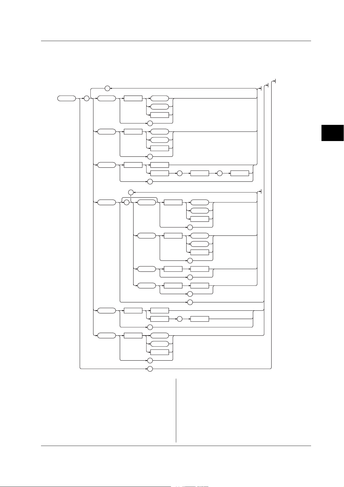
4.20 SYSTem Group
4.20 SYSTem Group
The commands in this group deal with basic system settings such as the date/time setting. You can make the
same settings and inquiries as when the Config menu or LCD menu of the UTILITY key on the front panel is
used.
;
:SYSTem : BEEP <Space> OFF
ON
<NRf
>
?
CLICksoun
d <Space> OFF
ON
<NRf>
?
TE <Space> <String>
DA
<NRf
> , <NRf> , <NRf>
?
;
LC
D :STAT e <Space> OFF
ON
<NRf>
?
AO
FF <Space> OFF
ON
<NRf
>
?
ATI Me <Space> <NRf>
?
BRIGhtness <Space> <NRf>
?
?
TIME <Space> <String>
<NRf
> , <NRf>
?
W
ARNing <Space> OFF
ON
<NRf>
?
?
4
Command
:SYSTem?
Function Queries all settings related to the SYSTem
group.
Syntax :SYSTem?
Example :SYSTEM?
-> :SYSTEM:BEEP 1:CLICKSOUND 1;LCD:
AOFF 0;STATE 1;BRIGHTNESS 4;:
SYSTEM:WARNING 0
:SYSTem:BEEP
Function Turns ON/OFF the beep sound or queries the
current setting.
Syntax :SYSTem:BEEP {<Boolean>}
:SYSTem:BEEP?
Example :SYSTEM:BEEP ON
:SYSTEM:BEEP?
-> :SYSTEM:BEEP 1
4-67IM 704510-17E
Page 91

4.20 SYSTem Group
:SYSTem:CLICksound
Function Turns ON/OFF the click sound or queries the
current setting.
Syntax :SYSTem:CLICksound {<Boolean>}
:SYSTem:CLICksound?
Example :SYSTEM:CLICKSOUND ON
:SYSTEM:CLICKSOUND?
-> :SYSTEM:CLICKSOUND 1
:SYSTem:DATE
Function Sets the date or queries the current setting.
Syntax :SYSTem:DATE {<Character
string>|,<NRf>,<NRf>,<NRf>}
:SYSTem:DATE?
Example :SYSTEM:DATE “2002/01/01”
:SYSTEM:DATE?
-> “2002/01/01”
Description <Character string> must be in the following
format: year (4 digits)/month (2 digits)/day (2
digits). When in the <NRf> form, specify the
date in the order year, month, and day.
:SYSTem:LCD?
Function Queries all settings related to the LCD.
Syntax :SYSTem:LCD?
Example :SYSTEM:LCD?
-> :SYSTEM:LCD:AOFF 1;ATIME 0
:SYSTem:LCD:AOFF
Function Turns ON/OFF the auto off function of the LCD
or queries the current setting.
Syntax :SYSTem:LCD:AOFF {<Boolean>}
:SYSTem:LCD:AOFF?
Example :SYSTEM:LCD:AOFF ON
:SYSTEM:LCD:AOFF?
-> :SYSTEM:LCD:AOFF 1
:SYSTem:LCD:ATIMe
Function Sets the auto off time of the LCD or queries the
current setting.
Syntax :SYSTem:LCD:ATIMe {<NRf>}
:SYSTem:LCD:ATIMe?
<NRf>=1 to 60 (minutes)
Example :SYSTEM:LCD:ATIME 15
:SYSTEM:LCD:ATIME?
-> :SYSTEM:LCD:ATIME 15
Description Setting is possible when “:SYSTEM:LCD:AOFF”
is set to “ON”.
:SYSTem:LCD:BRIGhtness
Function Sets the brightness of the LCD or queries the
current setting.
Syntax :SYSTem:LCD:BRIGhtness {<NRf>}
:SYSTem:LCD:BRIGhtness?
<NRf>=0 to 7
Example :SYSTEM:LCD:BRIGHTNESS
:SYSTEM:LCD:BRIGHTNESS?
-> :SYSTEM:LCD:BRIGHTNESS
:SYSTem:LCD[:STATe]
Function Turns ON/OFF the LCD backlight or queries the
current setting.
Syntax :SYSTem:LCD[:STATe] {<Boolean>}
:SYSTem:LCD:STATE?
Example :SYSTEM:LCD:STATE ON
:SYSTEM:LCD:STATE?
-> :SYSTEM:LCD:STATE 1
:SYSTem:TIME
Function Sets the time or queries the current setting.
Syntax :SYSTem:TIME {<Character
string>|,<NRf>,<NRf>}
:SYSTem:TIME?
Example :SYSTEM:TIME “12:00”
:SYSTEM:TIME?
-> “12:00:00”
Description <Character string> must be in the following
format: hour (2 digits):minutes (2 digits). When
in the <NRf> form, specify the time in the order
hour and minute. The response to a query
includes seconds.
:SYSTem:WARNing
Function Turns ON/OFF the warning display or queries
the current setting.
Syntax :SYSTem:WARNing <Boolean>
:SYSTem:WARNing?
Example :SYSTEM:WARNING ON
:SYSTEM:WARNING?
-> :SYSTEM:WARNING 1
4-68 IM 704510-17E
Page 92

4.21 TVARiation<x> Group
4.21 TVARiation<x> Group
The commands in this group deal with the time variation display in time stamp mode. You can make the same
settings and inquiries as when the DISPLAY, SCALE, and MARK keys on the front panel are used.
• When measuring the period, A-to-B time interval, or pulse width or when measuring period A & period B,
period A & A-to-B time interval, pulse width A & A-to-B time interval, and pulse width A & pulse width B, use
“TVARiation1” or “TVARiation” for the command for measurement 1. However, the query is
“TVARIATION1”.
• When measuring period A & period B, period A & A-to-B time interval, pulse width A & A-to-B time interval,
and pulse width A & pulse width B, use “TVARiation2” for the command for measurement 2.
;
;
:TVARiation :
HORizontal : MINimum <Space>
AN <Space>
SP
;
MARK
er :STAT e <Space> OFF
HIGH <Space>
LO
W
LEFT <Space>
RIGHt
Lue ?
LV A
RV
ALue
?
;
VER
Tical : CENTer <Space>
SP
AN <Space>
<Time><x>
?
<Time>
?
?
ON
<NRf>
?
<Time>
?
<Time>
?
<Time>
?
<Time>
?
?
?
4
Command
:TVARiation<x>?
Function Queries all settings related to time variation.
Syntax :TVARiation<x>?
<x>=1 to 2
Example :TVARIATION?
-> :TVARIATION1:HORIZONTAL:
MINIMUM 100.0E-09;SPAN 0.06E-03;:
TVARIATION1:MARKER:
HIGH 150.000E-09;LEFT 1.0E-06;
LOW 100.000E-09;RIGHT 2.0E-06;
STATE 1:TVARIATION1:VERTICAL:
CENTER 100.000E-09;SPAN 0.2E-06
:TVARiation<x>:HORizontal?
Function Queries all settings related to the horizontal axis
(X-axis) of the time variation display.
Syntax :TVARiation<x>:HORizontal?
<x>=1 to 2
Example :TVARIATION:HORIZONTAL?
-> :TVARIATION1:HORIZONTAL:
MINIMUM 100.0E-09;SPAN 0.06E-03
4-69IM 704510-17E
Page 93

4.21 TVARiation<x> Group
:TVARiation<x>:HORizontal:MINimum
Function Sets the left end of the horizontal axis (X-axis)
scale or queries the current setting.
Syntax :TVARiation<x>:HORizontal:MINimum
{<Time>}
:TVARiation<x>:HORizontal:MINimum?
<x>=1 to 2
<Time>=0 to 320 s (100 ns steps)
Example :TVARIATION1:HORIZONTAL:
MINIMUM 100ns
:TVARIATION1:HORIZONTAL:MINIMUM?
-> :TVARIATION1:HORIZONTAL:
MINIMUM 100.0E-09
:TVARiation<x>:HORizontal:SPAN
Function Sets the span of the horizontal axis (X-axis)
scale or queries the current setting.
Syntax :TVARiation<x>:HORizontal:SPAN
{<Time>}
:TVARiation<x>:HORizontal:SPAN?
<x>=1 to 2
<Time>=6 µs, 12 µs, 30 µs, 60 µs,
120 µs, 300 µs, 600 µs, 1.2 ms, 3
ms, 6 ms, 12 ms, 30 ms, 60 ms, 120
ms, 300 ms, 600 ms, 1.2 s, 3 s, 6
s, 12 s, 30 s, 60 s, 120 s, 300 s,
600 s
Example :TVARIATION1:HORIZONTAL:SPAN 60us
:TVARIATION1:HORIZONTAL:SPAN?
-> :TVARIATION1:HORIZONTAL:
SPAN 0.06E-03
:TVARiation<x>:MARKer?
Function Queries all settings related to the marker.
Syntax :TVARiation<x>:MARKer?
<x>=1 to 2
Example :TVARIATION1:MARKER?
-> :TVARIATION1:MARKER:
HIGH 150.000E-09;LEFT 1.0E-06;
LOW 100.000E-09;RIGHT 2.0E-06;
STATE 1
:TVARiation<x>:MARKer:{HIGH|LOW}
Function Sets the position of the high/low marker or
queries the current setting.
Syntax :TVARiation<x>:MARKer:{HIGH|LOW}
{<Time>}
:TVARiation<x>:MARKer:{HIGH|LOW}?
<x>=1 to 2
<Time>=Marker position (25 ps
steps)
Example (The following is an example for the high
marker.)
:TVARIATION1:MARKER:HIGH 150ns
:TVARIATION1:MARKER:HIGH?
-> :TVARIATION:MARKER:
HIGH 150.000E-09
:TVARiation<x>:MARKer:{LEFT|RIGHt}
Function Sets the position of the left/right marker or
queries the current setting.
Syntax :TVARiation:MARKer:{LEFT|RIGHt}
{<Time>}
:TVARiation:MARKer:{LEFT|RIGHt}?
<x>=1 to 2
<Time>=0 to 920 s (100 ns steps)
Example (The following is an example for the left marker.)
:TVARIATION1:MARKER:LEFT 150us
:TVARIATION1:MARKER:LEFT?
-> :TVARIATION1:MARKER:
LEFT 150.0E-03
:TVARiation<x>:MARKer:{LVALue|RVALue}?
Function Queries the measured value at the left/right
marker position.
Syntax :TVARiation<x>:MARKer:{LVALue|RVALue}?
<x>=1 to 2
Example (The following is an example for the left marker
position.)
:TVARIATION:MARKER:LVALUE?
-> 1.2000E-06
:TVARiation<x>:MARKer[:STATe]
Function Turns ON/OFF the marker cursor or queries the
current setting.
Syntax :TVARiation<x>:MARKer[:STATe]
{<Boolean>}
:TVARiation<x>:MARKer:STATe?
<x>=1 to 2
Example :TVARIATION1:MARKER:STATE ON
:TVARIATION1:MARKER:STATE?
-> :TVARIATION1:MARKER:STATE 1
:TVARiation<x>:VERTical?
Function Queries all settings related to the vertical axis
(Y-axis).
Syntax :TVARiation<x>:VERTical?
<x>=1 to 2
Example :TVARIATION1:VERTICAL:CENTER?
-> :TVARIATION1:VERTICAL:CENTER
100.000E-09;SPAN 0.2E-06
:TVARiation<x>:VERTical:CENTer
Function Queries the center value of the vertical axis (Y-
axis).
Syntax :TVARiation<x>:VERTical:CENTer
{<Time>}
:TVARiation<x>:VERTical:CENTer?
<x>=1 to 2
<Time>=–50 ns to 20 ms (25 ps
steps)
Example :TVARIATION1:VERTICAL:CENTER 100ns
:TVARIATION1:VERTICAL:CENTER?
-> :TVARIATION1:VERTICAL:
CENTER 100.000E-09
4-70 IM 704510-17E
Page 94

4.21 TVARiation<x> Group/4.22 UNIT Group
:TVARiation<x>:VERTical:SPAN
Function Queries the span of the vertical axis (Y-axis).
Syntax :TVARiation<x>:VERTical:SPAN
{<Time>}
:TVARiation<x>:VERTical:SPAN?
<x>=1 to 2
<Time>=500 ps, 1 ns, 2.5 ns, 5 ns,
10 ns, 20 ns, 50 ns, 100 ns, 200
ns, 500 ns, 1 µs, 2 µs, 5 µs, 10 µs,
20 µs, 50 µs, 100 µs, 200 µs, 500
µs, 1 ms, 2 ms, 5 ms, 10 ms, 20 ms
Example :TVARIATION1:VERTICAL:SPAN 200ns
:TVARIATION1:VERTICAL:SPAN?
-> :TVARIATION1:VERTICAL:
SPAN 0.2E-06
4.22 UNIT Group
The commands in this group deal with the default unit of voltage, time, and frequency data.
;
:UNIT
:
VOLTage <Space> <Multiplier> V
<Multiplier>
V
?
4
Command
TIME <Space> <Multiplier>
FREQuency <Space> <Multiplier> Hz
:UNIT?
Function Queries the default unit of voltage, time and
frequency.
Syntax :UNIT?
Example :UNIT?
-> :UNIT:FREQUENCY HZ;VOLTAGE V;
TIME S
:UNIT:VOLTage
Function Sets the default unit of voltage or queries the
current setting.
Syntax :UNIT:VOLTage {<Multiplier>}V
:UNIT:VOLTage?
<Multiplier> See section 3.4.
Example :UNIT:VOLTAGE V
:UNIT:VOLTAGE?
-> :UNIT:VOLTAGE V
S
<Multiplier>
S
?
<Multiplier>
Hz
?
?
:UNIT:TIME
Function Sets the default unit of time or queries the
current setting.
Syntax :UNIT:TIME {<Multiplier>}S
:UNIT:TIME?
<Multiplier> See section 3.4.
Example :UNIT:TIME s
:UNIT:TIME?
-> :UNIT:TIME S
:UNIT:FREQuency
Function Sets the default unit of frequency or queries the
current setting.
Syntax :UNIT:FREQuency {<Multiplier>}Hz
:UNIT:FREQuency?
<Multiplier> See section 3.4.
Example :UNIT:FREQuency HZ
:UNIT:FREQUENCY?
-> :UNIT:FREQUENCY HZ
4-71IM 704510-17E
Page 95

4.23 Common Command Group
4.23 Common Command Group
The commands in the common group are defined in the IEEE 488.2-1992 and are independent of the
instrument’s functions.
;
*
*
*
*
*
*
*
*
*
*
*
*
*
CAL
CLS
ESE
ESR
IDN
OPC
OPC
RST
SRE
STB
TRG
TST
WAI
<Space> <NRf>
<Space> <NRf>
?
?
?
?
?
?
?
?
*CAL?
Function Performs calibration and queries the result.
Syntax *CAL?
Example *CAL?
-> 0
Description If the calibration terminates normally, “0” is
returned. Otherwise, a non-zero value is
returned.
*CLS
Function Clears the standard event register, extended
event register, and error queue.
Syntax *CLS
Example *CLS
Description For details on the standard event register,
extended event register, and error queue, see
chapter 5, “Status Report.”
*ESE
Function Sets the standard event enable register or
queries the current setting.
Syntax *ESE {<NRf>}
*ESE?
<NRf>=0 to 255
Example *ESE 253
*ESE?
-> 253
Description For details on the standard event enable
register, see chapter 5, “Status Report.”
*ESR?
Function Queries the standard event register and clears
the register.
Syntax *ESR?
Example *ESR?
-> 253
Description For details on the standard event register, see
chapter 5, “Status Report.”
*IDN?
Function Queries the instrument model.
Syntax *IDN?
Example *IDN?
-> YOKOGAWA,704510,0,F1.01
Description A reply is returned in the following form:
manufacturer, model, serial number (always 0),
firmware version.
*OPC
Function Sets a “1” to the standard event register bit
upon the completion of the specified overlap
command. Because the TA720 does not
support overlap commands, the command is
discarded.
Syntax *OPC
*OPC?
Function Returns a “1” when the specified overlap
command is finished. A “1” is always returned,
because the TA720 does not support overlap
commands.
Syntax *OPC?
4-72 IM 704510-17E
Page 96

*RST
Function Initializes the setup data.
Syntax *RST
Example *RST
Description Executes the same operation as when the
[Execute] soft key of the INIT
(SHIFT+MARKER) key is pressed. For details
on initialization, see the
TA720 User’s Manual
*SRE
Function Sets the service request enable register or
queries the current setting.
Syntax *SRE {<NRf>}
*SRE?
<NRf>=0 to 255
Example *SRE 239
*SRE?
-> 239
*STB?
Function Queries the status byte register.
Syntax *STB?
Example *STB?
-> 4
Description For details on the status byte register, see
chapter 5, “Status Report.”
4.23 Common Command Group
.
4
Command
*TRG?
Function Executes the same operation as when the
SINGLE key is pressed.
Syntax *TRG?
Description The multi-line message GET (Group Execute
Trigger) also performs the same operation as
this command.
*TST?
Function Performs a self-test and queries the result.
Syntax *TST?
Example *TST?
-> 0
Description • Executes the same operation as the [Board]
test of the [Selftest] soft key.
• If the all the tests terminate normally, “0” is
returned. Otherwise, a non-zero value is
returned.
*WAI
Function Holds the subsequent command until the
completion of the specified overlap operation.
Because the TA720 does not support overlap
commands, the command is discarded.
Syntax *WAI
4-73IM 704510-17E
Page 97

5.1 Overview of the Status Report
Chapter 5 Status Report
5.1 Overview of the Status Report
Status Report
The figure below shows the status report that is read by serial polling. This status report is an extended version of
the status report defined in IEEE 488.2-1992.
OR
Occurrence
of a Service
Request
76543210
&
&
&
&
&
&
MSS
76ESBMAVEES EAV 1 0
RQS
Service Request Enable Register
&
Status Byte
Output
Queue
Error
Queue
5
Status Report
76543210
&
&
&
OR
76543210
15 14 13 12 11 10 9876543210
&
&
&
&
&
&
&
OR
15 14 13 12 11 10 9876543210
15 14 13 12 11 10 9876543210
15 14 13 12 11 10 9876543210
&
&
&
&
&
&
&
&
Standard Event Enable Register
&
&
&
Standard Event Register
Extended Event Enable Register
&
&
&
Extended Event Register
Transit Filter
Condition Filter
5-1IM 704510-17E
Page 98

5.1 Overview of the Status Report/5.2 Status Byte
Overview of the Registers and Queues
Name Function Writing Reading
Status byte – Serial polling (RQS),
*STB?(MSS)
Service request Masks status byte *SRE *SRE?
enable register
Standard event Changes in – *ESR?
register device status
Standard event Masks standard *ESE *ESE?
enable register event register
Extended event Changes in – STATus:EESR?
register device status
Extended event Masks extended STATus: STATus:EESE?
enable register event register EESE
Condition Current – STATus:
register instrument status CONDition?
Transition filter Conditions that STATus: STATus:FILTer
change the FILTer<x><x>?
extended event register
Output queue Stores a response All query commands
message to a
query
Error queue Stores the error – STATus:ERRor?
No. and message
Registers and Queues That Affect the Status Byte
Registers that affect the bits of the status byte are
shown below.
Standard event register: Sets bit 5 (ESB) of the status byte to “1”
or “0.”
Output queue: Sets bit 4 (MAV) of the status byte to “1”
or “0.”
Extended event register: Sets bit 3 (EES) of the status byte to “1”
or “0.”
Error queue: Sets bit 2 (EAV) of the status byte to “1”
or “0.”
Enable Registers
Registers that are used to mask a bit so that the bit will
not affect the status byte even when it is set to 1, are
shown below.
Status byte: Mask the bits using the service request
enable register.
Standard event register: Mask the bits using the standard event
enable register.
Extended event register: Mask the bits using the extended event
enable register.
Writing/Reading from Registers
The *ESE command is used to set the bits in the
standard event enable register to 1’s or 0’s. The
*ESE? command is used to query whether the bits in
the standard event enable register are 1’s or 0’s. For
details regarding these commands, see chapter 4.
5.2 Status Byte
Overview of Status Byte
RQS
76ESBMAV EES EAV 1 0
MSS
• Bits 0, 1, and 7
Not used (always 0)
• Bit 2 EAV (Error Available)
Set to “1” when the error queue is not empty. In
other words, this bit is set to “1” when an error
occurs. See the page 5-5.
• Bit 3 EES (Extend Event Summary Bit)
Set to “1” when the logical product of the extended
event register and the corresponding event register
is “1.” —that is, when an event takes place inside
the instrument. See the page 5-4.
• Bit 4 MAV (Message Available)
Set to “1” when the output queue is not empty. In
other words, this bit is set to “1” when there are data
to be transmitted. See the page 5-5.
• Bit 5 ESB (Event Summary Bit)
Set to “1” when the logical product of the standard
event register and the corresponding event register
is “1.” —that is, when an event takes place inside
the instrument. See the page 5-3.
• Bit 6 RQS (Request Service)/MSS (Master Status
Summary)
Set to “1” when the logical AND of the status byte
excluding Bit 6 and the service request enable
register is not “0.” In other words, this bit is set to
“1” when the instrument is requesting service from
the controller.
RQS is set to “1” when the MSS bit changes from
“0” to “1,” and cleared when serial polling is carried
out or when the MSS bit changes to “0.”
Bit Masking
To mask a bit in the status byte so that it does not
cause an SRQ, set the corresponding bit of the service
request enable register to “0.”
For example, to mask bit 2 (EAV) so that service is not
requested when an error occurs, set bit 2 of the service
request enable register to “0.” This can be done using
the *SRE command. To query whether each bit of the
service request enable register is “1” or “0,” use
*SRE?. For details on the *SRE command, see
chapter 4.
5-2 IM 704510-17E
Page 99

5.2 Status Byte/5.3 Standard Event Register
Operation of the Status Byte
A service request is issued when bit 6 of the status
byte becomes “1.” Bit 6 is set to “1” when any of the
other bits becomes a “1” (when the corresponding bit
of the service request enable register is also set to “1”).
For example, if an event takes place and the logical
OR of each bit of the standard event register and the
corresponding bit in the enable register is “1,” bit 5
(ESB) will be set to “1.” In this case, if bit 5 of the
service request enable register is “1,” bit 6 (MSS) will
be set to “1,” thus requesting service from the
controller.
It is also possible to check what type of event has
occurred by reading the contents of the status byte.
Reading from the Status Byte
The following two methods are provided for reading the
status byte.
• Inquiry using the *STB? query
Making an inquiry using the *STB? query sets bit 6
to MSS. This causes the MSS to be read. After
completion of the read-out, none of the bits in the
status byte will be cleared.
• Serial polling
Execution of a serial polling changes bit 6 to RQS.
This causes RQS to be read. After completion of
the read-out, only RQS is cleared. Using a serial
polling, it is not possible to read MSS.
Clearing the Status Byte
No method is provided for forcibly clearing all the bits
in the status byte. The bits that are cleared for each
operation are shown below.
• When an inquiry is made using the *STB? query
No bit is cleared.
• When a serial polling is executed
Only the RQS bit is cleared.
• When a *CLS command is received.
When the *CLS command is received, the status
byte itself is not cleared, but the contents of the
standard event register (which affects the bits in the
status byte) are cleared. As a result, the
corresponding bits in the status byte are cleared,
except bit 4 (MAV), since the output queue cannot
be emptied by the *CLS command. However, the
output queue will also be cleared if the *CLS
command is received just after a program message
terminator.
5.3 Standard Event Register
Overview of the Standard Event Register
6
7 543210
URQ
PON
• Bit 7 PON (Power ON)
• Bit 6 URQ (User Request)
• Bit 5 CME (Command Error)
• Bit 4 EXE (Execution Error)
• Bit 3 DDE (Device Dependent Error)
• Bit 2 QYE (Query Error)
• Bit 1 RQC (Request Control)
• Bit 0 OPC (Operation Complete)
Bit Masking
To mask a bit in the standard event register so that it
does not cause bit 5 (ESB) of the status byte to
change, set the corresponding bit in the standard event
enable register to “0.” Refer to Chapter 4.
For example, to mask bit 2 (QYE) so that ESB will not
be set to “1,” even if a query error occurs, set bit 2 of
the standard event enable register to “0.” This can be
done using the *ESE command. To inquire whether
each bit of the standard event enable register is “1” or
“0,” use the *ESE?. For details on the *ESE
command, see chapter 4.
CMEEXE DDEQYERQCOPC
Set to “1” when the power is turned ON.
Not used (always 0)
Set to “1” when the command syntax is incorrect.
Example Incorrectly spelled command name; “9”
used in octal data.
Set to “1” when the command syntax is correct but
the command cannot be executed in the current
state.
Example Parameters are outside the range.
Set to “1” when execution of the command is not
possible due to an internal problem in the
instrument that is not a command error or an
execution error.
Set to “1” if the output queue is empty or if the data
is missing even after a query has been sent.
Example No response data; data is lost due to an
overflow in the output queue.
Not used (always 0)
Set to “1” when the operation designated by the
*OPC command (see chapter 4) has been
completed.
5
Status Report
5-3IM 704510-17E
Page 100

5.3 Standard Event Register/3.3 Responses
Operation of the Standard Event Register
The standard event register is provided for eight
different kinds of event which can occur inside the
instrument. Bit 5 (ESB) of the status byte is set to “1”
Reading from the Standard Event Register
The contents of the standard event register can be
read by the *ESR command. After completion of the
read-out, the register will be cleared.
when any of the bits in this register becomes “1” (or
when the corresponding bit of the standard event
enable register becomes “1”).
Example
1. A query error occurs.
2. Bit 2 (QYE) is set to “1.”
3. Bit 5 (ESB) of the status byte is set to “1” if bit 2 of
the standard event enable register is “1.”
Clearing the Standard Event Register
The standard event register is cleared in the following
three cases.
• When the contents of the standard event register
are read using the *ESR command.
• When a *CLS command is received.
• When the instrument is power cycled.
It is also possible to check what type of event has
occurred inside the instrument by reading the contents
of the standard event register.
5.4 Extended Event Register
Reading the extended event register tells you whether changes in the condition register (reflecting internal
conditions) have occurred. A filter can be applied which allows you to decide which events are reported to
the extended event register.
FILTer<x> ->
Condition Register
:STATus:CONDition?
16
15
HCP
14
ACS
13
TST
12
CAL
11
7 543210
8
9
10
ISF
NSP
0
NRC
RTF
67 5432189101112131415
6
ETF MTF SOV TOV DOV DATCMF
Transition Filter
:STATus:FILTer<x>
{RISE|FALL|BOTH|NEVer}
Extended Event Register
:STATus:EESR?
67 54321089101112131415
01415
1
67 5438910111213
2
The meaning of each bit of the condition register is as follows.
Bit 0 DAT(DATa available) Set to “1” when the measured data and the computation result are valid.
Bit 1 DOV(Data OVerflow) Set to “1” when a measured data causes an overflow.
Bit 2 TOV(Time stamp OVerflow) Set to “1” when a time stamp data causes an overflow.
Bit 3 SOV(Sample OVerflow) Set to “1” when the number of measured samples causes an overflow.
Bit 4 MTF(Measured T Failure) Set to “1” when the measurement of measured T fails.
Bit 5 ETF(Estimated T Failure) Set to “1” when the measurement of estimated T fails.
Bit 6 RTF(Rest Time Failure) Set to “1” when the pause time of block sampling falls short of 500 ns.
Bit 7 NRC(No Reference Clock) Set to “1” when no reference signal is present.
Bit 8 CMF(Continuation Measurement Failure) Set to “1” when continuous measurement fails.
Bit 9 ISF(ISI analysis Failure) Set to “1” when inter-symbol interference analysis fails.
Bit 10 NSP(No Sync Pattern) Set to “1” when simbol seach fails.
Bit 11 Reserved Not used.
Bit 12 CAL(CALibration) Set to “1” while calibration is in progress.
Bit 13 TST(TeSTing) Set to “1” while self-test is in progress.
Bit 14 ACS(file ACceSsing) Set to “1” while the storage medium is being accessed.
Bit 15 HCP(Hard-CoPying) Set to “1” while hard copy is in progress.
The transition filter parameters detect changes in the specified bit (numerical suffix, 1 to 16) of the condition
register in the following manner and overwrite the extended event register.
RISE The bit of the extended event register becomes “1” when the bit of the condition register changes from “0” to “1.”
FALL The bit of the extended event register becomes “1” when the bit of the condition register changes from “1” to “0.”
BOTH The bit of the extended event register becomes “1” when the bit of the condition register changes from “0” to “1,” or from “1” to “0.”
NEVer Always 0.
5-4 IM 704510-17E
 Loading...