

Page 1

Time Interval Analyzer
GP-IB Interface
IM 704310-12E
2nd Edition
Page 2

Foreword
Notices
LOCAL key
GP-IB connector
Thank you for purchasing YOKOGAWA's TA520 Time Interval Analyzer.
This GP-IB Interface User
's Manual contains useful information about the functions and
commands of the GP-IB interface. To ensure correct use of the GP-IB interface, please
read this manual thoroughly before operating it.
Keep the manual in a safe place for quick reference whenever a question arises.
The following manual is provided with this instrument in addition to this GP-IB Interface
's Manual.
User
Manual Name Manual No. Description
TA520 User's Manual IM 704310-01E Describes all functions except for the
communications functions for GP-IB interface of
the instrument.
• The contents of this manual are subject to change without prior notice as a result of
improvements in the instrument
's performance and functions.
• Every effort has been made in the preparation of this manual to ensure the accuracy
of its contents. However, should you have any questions or find any errors, please
contact your nearest YOKOGAWA representative as listed on the back cover of this
manual.
• Copying or reproduction of all or any part of the contents of this manual without
YOKOGAWA's permission is strictly prohibited.
Trademarks
Revisions
• IBM PC/AT is a registered trademark of International Business Machines Corporation.
• Other product names are trademarks or registered trademarks of their respective
holders.
• 1st Edition: April 1999
• 2nd Edition: November 1999
Disk No. HF09
2nd Edition:November 1999 (YK)
All Rights Reserved, Copyright © 1999 Yokogawa Electric Corporation
iIM 704310-12E
Page 3

How to Use this Manual
Structure of this Manual
This User's Manual consists of five chapters, an appendix and an index as described
below.
Chapter 1 Overview of the GP-IB Interface
Describes the functions and specifications of GP-IB.
Chapter 2 Before Programming
Describes formats used when sending a command.
Chapter 3 Commands
Describes each command.
Chapter 4 Status Report
Describes the status byte, various registers and queues.
Chapter 5 Sample Program
Describes a program example written for a IBM PC/AT series personal
computer written in Quick BASIC version 4.0/4.5.
Appendix
Index
Conventions Used in this Manual
Symbols used for Notes and Keys
Type Symbol Description
Unit k 1000 e.g.: 100 kHz
K 1024 e.g.: 128 KB (memory capacity)
Note
Note
Symbols used in syntax descriptions
Symbols which are used in the syntax descriptions in Chapter 4 are shown below. These
symbols are referred to as BNF notation (Backus-Naur Form). For detailed information,
refer to pages 2-5 and 2-6.
Symbol Description Example Example
<> Defined value WINDow<x> <x>=1 to 16 WINDOW2
{} One of the options in is selected. MODE {AUTO|MANual} MODE AUTO
| Exclusive OR MODE {AUTO|MANual} MODE AUTO
[ ] Abbreviated :MEASure[:MODE]
... May be repeated
Contains references including the ASCII character code table.
Provides an alphabetically ordered index.
Provides information that is necessary for proper operation of the instrument.
ii IM 704310-12E
Page 4

Contents
1
Foreword............................................................................................................................................................. i
How to Use this Manual.............................................................................................................................ii
Chapter 1 Overview of the GP-IB Interface
1.1 Name of the Parts and Their Functions .................................................................................... 1-1
1.2 Connecting the GP-IB Cable..................................................................................................... 1-2
1.3 GP-IB Interface Functions and Specifications .......................................................................... 1-3
1.4 Settings on the Main Unit ..........................................................................................................1-5
1.5 Responses to Interface Messages............................................................................................ 1-6
Chapter 2 Before Programming
2.1 Messages.................................................................................................................................. 2-1
2.2 Commands................................................................................................................................ 2-3
2.3 Response ..................................................................................................................................2-5
2.4 Data .......................................................................................................................................... 2-5
2.5 Synchronization with the Controller .......................................................................................... 2-7
Chapter 3 Commands
3.1 Command Listing ...................................................................................................................... 3-1
3.2 ASCale Group ...........................................................................................................................3-9
3.3 CALCulation Group ................................................................................................................. 3-10
3.4 COMMunicate Group .............................................................................................................. 3-20
3.5 DISPlay Group ........................................................................................................................ 3-21
3.6 FILE Group ............................................................................................................................. 3-25
3.7 HCOPy Group ......................................................................................................................... 3-28
3.8 HHIStogram Group ................................................................................................................. 3-30
3.9 INPut Group ............................................................................................................................ 3-36
3.10 MEASure Group...................................................................................................................... 3-39
3.11 MEMory Group........................................................................................................................ 3-40
3.12 RECall Group .......................................................................................................................... 3-41
3.13 SAMPle Group ........................................................................................................................ 3-42
3.14 SCSI Group............................................................................................................................. 3-46
3.15 SSTart Group .......................................................................................................................... 3-46
3.16 STARt Group...........................................................................................................................3-46
3.17 STATus Group......................................................................................................................... 3-47
3.18 STOP Group ........................................................................................................................... 3-48
3.19 STORe Group ......................................................................................................................... 3-48
3.20 SYSTem Group ....................................................................................................................... 3-48
3.21 THIStogram Group.................................................................................................................. 3-50
3.22 TVARiation Group ................................................................................................................... 3-56
3.23 UNIT Group............................................................................................................................. 3-58
3.24 Common Command Group ..................................................................................................... 3-59
2
3
4
5
App
Index
iiiIM 704310-12E
Page 5

1.3 GP-IB Interface Functions and Specifications
Chapter 4 Status Repor t
4.1 Overview of the Status Report .................................................................................................. 4-1
4.2 Status Byte................................................................................................................................ 4-2
4.3 Standard Event Register ........................................................................................................... 4-3
4.4 Extended Event Register ..........................................................................................................4-4
4.5 Output Queue and Error Queue................................................................................................ 4-5
Chapter 5 Sample Program
5.1 Before Writing the Program.......................................................................................................5-1
5.2 Setup Example.......................................................................................................................... 5-1
5.3 Example of Statistical Data Output ...........................................................................................5-2
5.4 Example of Output in BINARY Format...................................................................................... 5-4
5.5 Example of Output in ASCII Format.......................................................................................... 5-5
Appendix
Appendix 1 ASCII Character Code...................................................................................................App-1
Appendix 2 Error Messages .............................................................................................................App-2
Appendix 3 Overview of IEEE 488.2-1992 .......................................................................................App-5
Index........................................................................................................................................................... Index-1
iv IM 704310-12E
Page 6
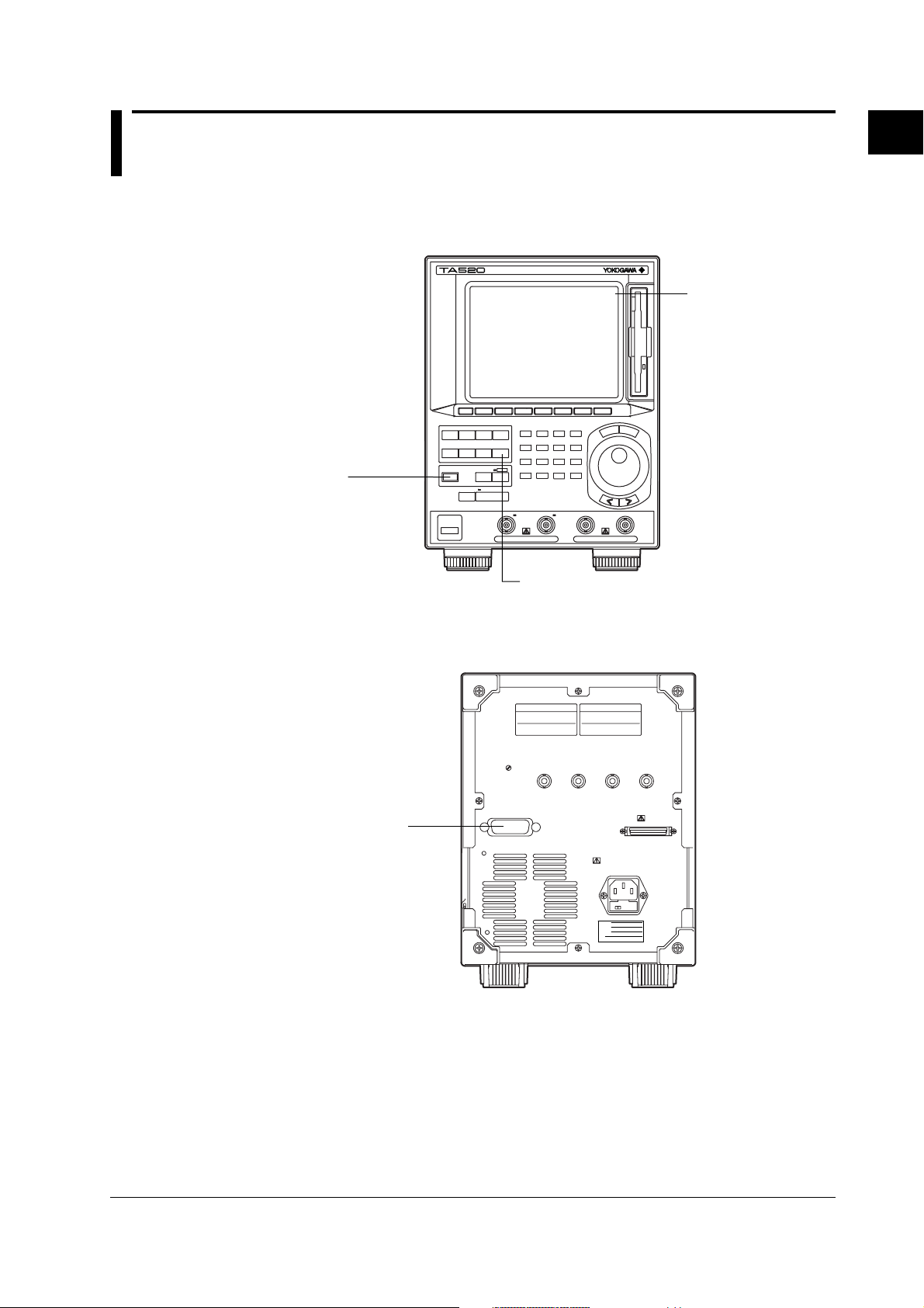
LOCAL key
GP-IB connector
1.1 Name of the Parts and Their Functions
Chapter 1 Overview of the GP-IB Interface
1.1 Name of the Parts and Their Functions
Front Panel
Remote
LOCAL key
(SHIFT+AUTO SCALE)
key
Press to cancel the
remote mode and enter
the local mode in which
the panel keys are
enabled.
AB
CH
EXT ARM/GATE IN
CH
UTILITY key
Press to enter the
communication settings.
INHIBIT IN
1
Overview of the GP-IB Interface
The word [Remote]
appears in the top right
corner of the screen
when the instrument is in
the remote mode.
Rear Panel
GP-IB connector
The connector used for
connecting the controller
(PC) with the GP-IB
cable.
1-1IM 704310-12E
Page 7
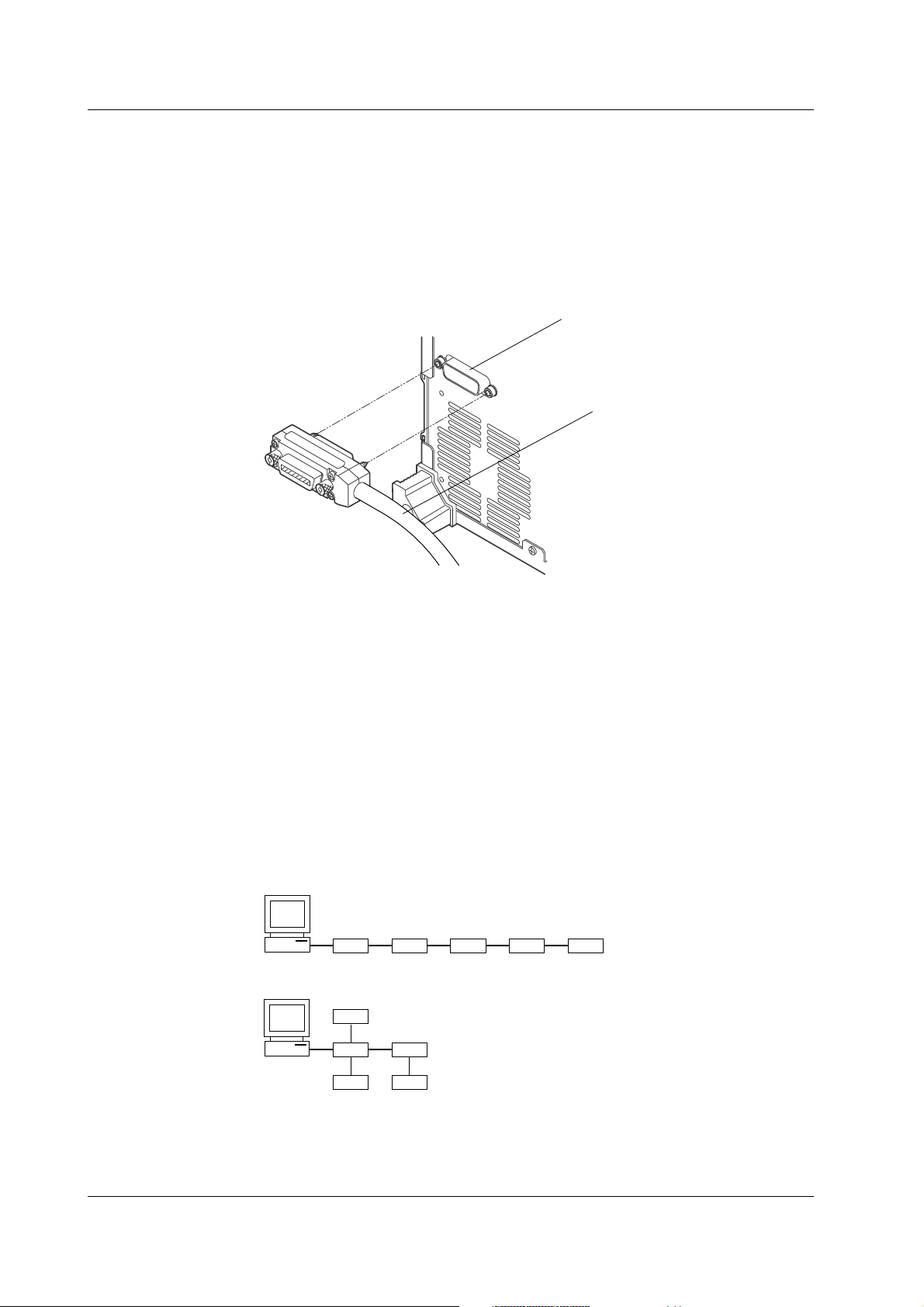
1.2 Connecting the GP-IB Cable
1.2 Connecting the GP-IB Cable
GP-IB Cable
The GP-IB connector on the rear panel is a 24-pin connector that conforms to IEEE
Standard 488-1978. Use a GP-IB cable that also conforms to IEEE Standard 488-1978.
Connection Method
Connect the GP-IB cable as shown.
GP-IB connector
GP-IB cable
Points to Note
• Be sure to tighten the screws on the GP-IB cable connector firmly.
• The instrument can be connected to more than one item of equipment (such as a
personal computer). However, it is not possible to connect more than 15 items of
equipment (including the controller) to a single bus.
• If you connect the instrument to more than one other item of equipment, make sure
that a different address is used for each item.
• Each connecting cable must be 2 m or less in length.
• The total length of all the cables must not exceed 20 m.
• While communications are in progress, more than two-thirds of the connected items of
equipment must be turned ON.
• When connecting more than one item of equipment, connect the items so that the
connection route forms a star or linear configuration. Loop or parallel wiring is not
allowed.
1-2 IM 704310-12E
Page 8

1.3 GP-IB Interface Functions and Specifications
1.3 GP-IB Interface Functions and Specifications
GP-IB Interface Functions
Listener function
• Allows you to make the same settings which you can make using the panel keys on
the instrument (except for the power ON/OFF and GP-IB communications settings).
• Receives commands from a controller requesting output of set-up and waveform data.
• Also receives status report commands.
Talker function
Outputs set-up and waveform data.
Note
The listen-only, talk-only, and controller functions are not available on this instrument.
Switching between Remote and Local Modes
Switching from Local to Remote Mode
Remote mode is activated when a REN (Remote Enable) message is received from a
controller while local mode is active.
• The word [Remote] appears in the top right corner of the screen (see page 1-1).
• All front panel keys except the LOCAL key are now inoperative.
• Settings that were entered in local mode are retained.
1
Overview of the GP-IB Interface
Switching from Remote to Local Mode
Pressing the Local key in remote mode puts the instrument in local mode. However, this
is not possible if Local Lockout has been set by the controller (page 1-7).
• The word [Remote] in the top right corner of the screen disappears (see page 1-1).
• All front panel keys are operative.
• Settings that were entered in remote mode are retained.
1-3IM 704310-12E
Page 9

1.3 GP-IB Interface Functions and Specifications
GP-IB Interface Specifications
Electrical and mechanical specifications: Conforms to IEEE Standard 488-1978.
Mechanical specifications : Refer to the table below.
Code : ISO (ASCII) code
Mode : Addressable mode/Talk-only mode (switched
Address setting : Addresses 0 to 30 can be selected from the
Remote mode clear : Remote mode can be cleared by pressing the
Mechanical Specifications
Function Subset Name Description
Source handshaking SH1 Full source handshaking capability
Acceptor handshaking AH1 Full acceptor handshaking capability
Talker T6 Basic talker capability, serial polling,
Listener L4 Basic listener capability, unlisten on MTA
Service request SR1 Full service request capability
Remote local RL1 Full remote/local capability
Parallel poll PP0 No parallel polling capability
Device clear DC1 Full device clear capability
Device trigger DT0 No device trigger capability
Controller C0 No controller function
Electrical characteristic E1 Open collector
automatically)
GP-IB setting menu, which is displayed when
you press [GP-IB] soft key after having pressed
the UTILITY key.
LOCAL key (SHIFT+AUTO SCALE key).
However, this is not possible if Local Lockout
has been set by the controller.
untalk on MLA(My Listen Address), No
talk-only capability
(My Talk Address), no listen-only capability
1-4 IM 704310-12E
Page 10
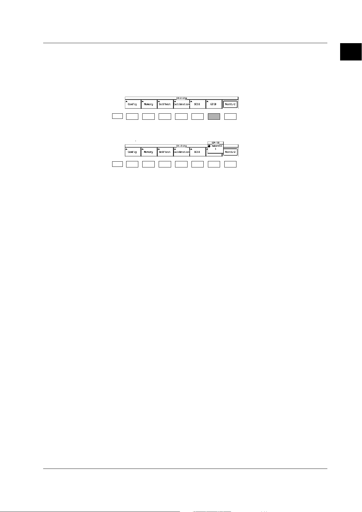
1.4 Settings on the Main Unit
1.4 Settings on the Main Unit
Procedure
1. Press the UTILITY key to display the Utility menu.
2. Press the [GP-IB] soft key to display the GP-IB menu.
ESC
3. Use the rotary knob to select the address.
ESC
Explanation
Selecting the address
Devices that are connected with the GP-IB cable have their own unique address within
the GP-IB system. This address is used to identify the different devices. Therefore,
when connecting the instrument to another device such as a PC, the address of the
instrument must be selected. The address is selected from the following range. The
default setting is [1].
Selectable range: 0 to 30
1
Overview of the GP-IB Interface
1-5IM 704310-12E
Page 11

1.5 Responses to Interface Messages
1.5 Responses to Interface Messages
What is an Interface Message?
An interface message (also called an interface command or bus command) is issued by
the controller. Interface messages are classified as follows.
Uni-line messages
Messages are transferred through a single control line. The following three types of uniline message are available.
• IFC (Interface Clear)
• REN (Remote Enable)
• IDY (Identify)
Multi-line messages
Eight data lines are used to transmit a message. Multi-line messages are classified as
follows.
Address commands
Valid when a piece of equipment is designated as a listener or a talker. The following
five address commands are available.
• Commands valid for pieces of equipment designated as listeners
GTL (Go To Local)
SDC (Selected Device Clear)
PPC (Parallel Poll Configure)
GET (Group Execute Trigger)
• Command valid for pieces of equipment designated as talkers
TCT (Take Control)
Universal commands
Valid for any item of equipment, irrespective of whether the item is designated as a
listener or a talker. The following five universal commands are available.
LLO (Local Lockout)
DCL (Device Clear)
PPU (Parallel Poll Unconfigure)
SPE (Serial Poll Enable)
SPD (Serial Poll Disable)
In addition to the above commands, a listener address, talker address or secondary
command can be sent in an interface message.
Differences between SDC and DCL
The SDC command is an address command and requires that both the talker and
listener be designated. DCL is a universal command and does not require that the
talker and listener be designated. Hence, SDC is used for specific items of equipment,
while DCL can be used for any equipment connected to the communications bus.
1-6 IM 704310-12E
Page 12

1.5 Responses to Interface Messages
Response to Interface Message
Response to a uni-line message
• IFC (Interface Clear)
Clears the talker and listener. Stops output if data is being output.
• REN (Remote Enable)
Switches between remote and local modes.
• IDY (Identify) is not supported.
Responses to a multi-line message (address command)
• GTL (Go To Local)
Switches to local mode.
• SDC (Selected Device Clear)
Clears the program message (command) which is currently being output. Also empties
the output queue (page 4-5).
• GET (Group Execute Trigger)
Same as *TRG.
•
COMMunicate:WAIT will be stopped immediately.
• PPC (Parallel Poll Configure) and TCT (Take Control) are not supported.
Responses to a multi-line message (universal command)
• LLO (Local Lockout)
Invalidates the LOCAL key on the front panel, disabling switching to local mode.
• DCL (Device Clear)
Same as SDC.
• SPE (Serial Poll Enable)
Sets the talker function to serial poll mode for all equipment connected to the
communications bus. The controller polls equipment sequentially.
• SPD (Serial Poll Disable)
Clears serial poll mode as the talker function for all equipment connected to the
communications bus.
• PPU (Parallel Poll Unconfigure) is not supported.
1
Overview of the GP-IB Interface
1-7IM 704310-12E
Page 13

Chapter 2 Before Programming
,
<Program header>
<Program data>Space
2.1 Messages
2.1 Messages
Messages
Blocks of message data are transferred between the
controller and this instrument during communications.
Messages sent from the controller to this instrument
are called program messages, and messages sent
back from this instrument to the controller are called
response messages.
If a program message contains a query command, i.e.
a command which requests a response, this
instrument returns a response message. A single
response message is always returned in reply to a
program message.
Program Messages
As explained above, the data (message) sent from the
controller to this instrument is called a program
message. The format of a program message is shown
below.
;
Program message unit
<PMT>
<PMT>
PMT is a terminator used to terminate each program
message. The following three types of terminator are
available.
NL (New Line) : Same as LF (Line Feed). ASCII code
"0AH" is used.
^END : END message defined in IEEE488.1.
(EOI signal)
(The data byte sent with an END
message will be the final item of the
program message unit.)
NL^END : NL with an END message attached
(NL is not included in the program
message.)
Program message unit format
The format of a program message unit is shown below.
<Program header>
A program header is used to indicate the command
type. For details, refer to page 2-3.
2
Before Programming
<Program message unit>
A program message consists of zero or more program
message units; each unit corresponds to one
command. This instrument executes commands one
by one according to the order in which they are
received.
Program message units are delimited by a ";".
For a description of the format of the program
message unit, refer to the explanation given further
below.
Example
:MEASURE:MODE HHISTOGRAM;FUNCTION PERIOD,A<PMT>
Unit Unit
<Program data>
If certain conditions are required for the execution of a
command, program data must be added. Program data
must be separated from the header by a space (ASCII
code "20H"). If multiple items of program data are
included, they must be separated by a
"," (comma).
For details, refer to page 2-5.
Example
:SAMPLE:GATE:MODE EVENT<PMT>
Header
Data
2-1IM 704310-12E
Page 14

2.1 Messages
Response Messages
The data returned by this instrument to the controller is
called a response message. The format of a response
message is shown below.
;
<Response message unit>
<RMT>
<Response message units>
A response message consists of one or more
response message units: each response message unit
corresponds to one response.
Response message units are delimited by a [ ;].
For the response message format, refer to the next
page.
Example
:SAMPLE:GATE:MODE EXTERNAL;POLARITY POSITIVE<RMT>
Unit Unit
<RMT>
RMT is the terminator used for every response
message. Only one type of response message is
available;
NL^END.
Response message unit format
The format of a program message unit is shown below.
,
<Rsps. header> <Response data>
Space
<Response header>
A response header sometimes precedes the response
data. Response data must be separated from the
header by a space. For details, refer to page 2-4.
<Response data>
Response data is used to define a response. If multiple
items of response data are used, they must be
separated by a "," (comma). For details, refer to page
2-5.
Example
500.0E-03<RMT> :SAMPLE:INTERVAL MINIMUM<RMT>
Data Header Data
If a program message contains more than one query,
responses are made in the same order as the queries.
Normally, each query returns only one response
message unit, but there are some queries which return
more than one response message unit. The first
response message unit always responds to the first
query, but it is not always true that the 'n'th unit
always responds to the
'n'th query. Therefore, if you
want to make sure that a response is made to each
query, the program message must be divided up into
individual messages.
Points to Note concerning Message Transmission
• It is always possible to send a program message if
the previous message which was sent did not
contain any queries.
• If the previous message contained a query, it is not
possible to send another program message until a
response message has been received. An error will
occur if a program message is sent before a
response message has been received in its entirety.
A response message which has not been received
will be discarded.
• If an attempt is made by the controller to receive a
response message, even if there it no response
message, an error will occur. An error will also occur
if the controller makes an attempt to receive a
response message before transmission of a
program message has been completed.
• If a program message of more than one unit is sent
and some of the units are incomplete, this
instrument receives program message units which
the instrument thinks complete and attempts to
execute them. However, these attempts may not
always be successful and a response may not
always be returned, even if the program message
contains queries.
Dead Lock
This instrument has a buffer memory in which both
program and response messages of 1024 bytes or
more can be stored. (The number of bytes available
will vary depending on the operating state of the
instrument.) If both buffer memories become full at the
same time, this instrument becomes inoperative. This
state is called dead lock. In this case, operation can be
resumed by discarding the response message.
No dead lock will occur, if the size of the program
message including the PMT is kept below 1024 bytes.
Furthermore, no dead lock will occur if the program
message does not contain a query.
2-2 IM 704310-12E
Page 15

2.2 Commands
2.2 Commands
Commands
There are three types of command (program header)
which can be sent from the controller to this
instrument. They differ in the format of their program
headers.
They are
• Common command header
• Compound header
• Simple header
Common Command Header
Commands defined in IEEE 488.2-1992 are called
common commands. The header format of a common
command is shown below. An asterisk (
be attached to the beginning of a command.
*
<Mnemonic>
?
An example of a common command
*CLS
*) must always
When Concatenating Commands
Command Group
A command group is a group of commands which have
the same compound header. A command group may
contain sub-groups.
Example Commands relating to the sampling
SAMPLE? SAMPLE:GATE?
SAMPLE:GATE:MODE SAMPLE:GATE:EVENTSIZE
SAMPLE:GATE:POLARITY SAMPLE:GATE:TIME
SAMPLE:INTERVAL SAMPLE:ARMING:SOURCE
SAMPLE:ARMING:DELAY:MODE
SAMPLE:ARMING:DELAY:TIME
When Concatenating Commands of the Same
Group
This instrument stores the hierarchical level of the
command which is currently being executed, and
performs analysis on the assumption that the next
command to be sent will also belong to the same level.
Therefore, it is possible to omit the header if the
commands belong to the same group.
2
Before Programming
Compound Header
Commands designed to be used only with this
instrument are classified and arranged in a hierarchy
according to their function. The format of a compound
header is illustrated below. A colon ( :) must be used
when specifying a lower-level header.
:
<Mnemonic>
?:
An example of a compound header
MEASURE:FUNCTION
Simple Header
These commands (headers) are functionally
independent of each other and are not arranged
hierarchically. The format of a simple header is shown
below.
<Mnemonic>
?:
An example of a simple header
START
Note
A mnemonic is a character string made up of alphanumeric
characters.
Example
INPUT:ACHANNEL:COUPLING AC;IMPEDANCE
I50<PMT>
When Concatenating Commands of Different
Groups
A colon ( :) must be included before the header of a
command, if the command does not belong to the
same group as the preceding command.
Example MEASURE:MODE TSTAMP;:DISPLAY:ITEM
LIST<PMT>
When Concatenating Simple Headers
When you type in a simple header after another
command, you must include a colon ( :) before the
simple header.
Example
MEASURE:MODE TSTAMP;:START<PMT>
When Concatenating Common Commands
Common commands defined in IEEE 488.2-1992 are
independent of hierarchical level. Thus, it is not
necessary to add a colon (
:) before a common
command.
Example
MEASURE:MODE TSTAMP;*CLS;FUNCTION
DUTY,A<PMT>
2-3IM 704310-12E
Page 16

2.2 Commands
When Separating Commands with <PMT>
If a terminator is used to separate two commands,
each command is a separate message. Therefore, the
common header must be typed in for each command
even when commands of the same command group
are being concatenated.
Example
MEASURE:MODE TSTAMP<PMT>MEASURE:
FUNCTION DUTY,A<PMT>
Upper-level Query
An upper-level query is a compound header to which a
question mark is appended. Execution of an upperlevel query allows all a group
's settings to be output at
once. Some query groups comprising more than three
hierarchical levels can output all their lower level
settings.
Example
MEASURE?<PMT>→:MEASURE:
MODE HHISTOGRAM;FUNCTION PERIOD,A;
SLOPE RISE
In reply to a query, a response can be returned as a
program message to this instrument. Transmitting a
response can restore the settings made when the
query was executed. However, some upper-level
queries will not return set-up data which is not currently
in use. Note that not all a group
's information will
necessarily be sent out as a response.
Header Interpretation Rules
This instrument interprets the header received
according to the following rules.
• Mnemonics are not case sensitive.
Example
"MEASure" can also be written as
"measure" or "Measure".
• The lower-case part of a header can be omitted.
Example "MEASure" can also be written as
"MEASU" or "MEAS".
• If the header ends with a question mark, the
command is a query. It is not possible to omit the
question mark.
Example "MEASure?" cannot be abbreviated to
• If the
"x" at the end of a mnemonic is omitted, it is
assumed to be
Example If
anything shorter than
"1".
"WINDow<x>" is written as "WIND", this
represents
"WINDow1".
"MEAS?".
• Any part of a command enclosed by [ ] can be
omitted.
Example
CALCulation[:WINDow1]:AVERage? can
be written as
"CALCulation:AVERage?".
However, a part enclosed by [ ] cannot be omitted if is
located at the end of an upper-level query.
2-4 IM 704310-12E
Page 17

2.3 Response/2.4 Data
2.3 Response
On receiving a query from the controller, this
instrument returns a response message to the
controller. A response message is sent in one of the
following two forms.
• Response consisting of a header and data
If the query can be used as a program message
without any change, a command header is attached
to the query, which is then returned.
Example
• Response consisting of data only
If the query cannot be used as a program message
unless changes are made to it (i.e. it is a query-only
command), no header is attached and only the data
is returned. Some query-only commands can be
returned after a header is attached to them.
Example STATUS:ERROR?<PMT>→
When returning a response without a header
It is possible to remove the header from a response
consisting of a header and data. The
"COMMunicate:HEADer" command is used to do this.
Abbreviated form
Normally, the lower-case part is removed from a
response header before the response is returned to
the controller. Naturally, the full form of the header can
also be used. For this, the "COMMunicate:VERBose"
command is used. The part enclosed by [ ] is also
omitted in the abbreviated form.
SAMPLE:GATE:MODE?<PMT>→:
SAMPLE:GATE:MODE EVENT<RMT>
0,"NO ERROR"<RMT>
2.4 Data
Data
A data section comes after the header. A space must
be included between the header and the data. The
data contains conditions and values. Data is classified
as below.
Data Description
<Decimal> Value expressed as a decimal number
(Example: CH2's probe attenuation
→SAMPle:GATE:EVENtsize 100)
<Voltage><Time> Physical value
(Example: Gate time
<Percent> →SAMPle:GATE:TIME 1US)
<Register> Register value expressed as either binary, octal, decimal
or hexadecimal
(Example: Extended event register value
→STATus:EESE #HFE)
<Character data> Specified character string (mnemonic). Can be selected
from { }
(Example: Selecting of gate mode
→SAMPle:GATE:MODE {EVENt|TIME|EXTernal})
<Boolean> Indicates ON/OFF. Set to ON, OFF or value
(Example: Panorama display ON
→DISPlay:PANorama:STATe ON)
<Character string data>Arbitrary character string
(Example: File name to be saved
→FILE:DELete:SETup "SETUP_1")
<Block data> Arbitrary 8-bit data
(Example: Response to acquired waveform data
→#6000010ABCDEFGHIJ)
<Decimal>
<<Decimal> indicates a value expressed as a decimal
number, as shown in the table below. Decimal values
are given in the NR form specified in ANSI X3. 42-
1975.
Symbol Description Example
<NR1> Integer 125 –1 +100000
<NR2> Fixed point number 125.0 –.90 +001.
<NR3> Floating point number 125.0E+0 –9E–1 +.1E4
<NRf> Any of the forms <NR1> to <NR3> is allowed.
2
Before Programming
• Decimal values which are sent from the controller to
this instrument can be sent in any of the forms to
<NR3>. In this case, <NRf> appears.
• For response messages which are returned from
this instrument to the controller, the form (<NR1> to
<NR3> to be used) is determined by the query. The
same form is used, irrespective of whether the value
is large or small.
• In the case of <NR3>, the "+" after the "E" can be
omitted, but the
"–" cannot.
• If a value outside the setting range is entered, the
value will be normalized so that it is just inside the
range.
• If the value has more than the significant number of
digits, the value will be rounded.
2-5IM 704310-12E
Page 18

2.4 Data
<Voltage>, <Time>, <Percent>
<Voltage>, <Time> and <Percent> indicate decimal
values which have physical significance. <Multiplier>
or <Unit> can be attached to <NRf>. They can be
entered in any of the following forms.
Form Example
<NRf><Multiplier><Unit> 5MV
<NRf><Unit> 5E-3V
<NRf><Multiplier> 5M
<NRf> 5E-3
<Multiplier>
Multipliers which can be used are shown below.
Symbol Word Description
EX Exa 10
PE Peta 10
T Tera 10
GGiga 10
MA Mega 10
K Kilo 10
M Mili 10
U Micro 10
N Nano 10
P Pico 10
F Femto 10
A Atto 10
18
15
12
9
6
3
-3
-6
-9
-12
-15
-18
<Unit>
Units which can be used are shown below.
Symbol Word Description
V Volt Voltage
S Second Time
PCT Percent Percent
<Register>
<Register> indicates an integer, and can be expressed
in hexadecimal, octal or binary as well as as a decimal
number. <Register> is used when each bit of a value
has a particular meaning. <Register> is expressed in
one of the following forms.
Form Example
<NRf> 1
#H<Hexadecimal value made up of the digits 0 to 9, and A to F> #H0F
#Q<Octal value made up of the digits 0 to 7> #q777
#B<Binary value made up of the digits 0 and 1> #B001100
• <Register> is not case sensitive.
• Response messages are always expressed as
<NR1>.
<Character Data>
<Character data> is a specified string of character data
(a mnemonic). It is mainly used to indicate options, and
is chosen from the character strings given in { }. For
interpretation rules, refer to "Header Interpretation
" on page 2-4.
Rules
Form Example
{EVENt|TIME|EXTernal} EVENt
• As with a header, the "COMMunicate:VERBose"
command can be used to return a response
message in its full form. Alternatively, the
abbreviated form can be used.
• The
"COMMunicate:HEADer" command does not
affect <character data>.
• <Multiplier> and <Unit> are not case sensitive.
• [U] is used to indicate [ µ].
• [MA] is used for Mega (M) to distinguish it from Mili.
• If both <Multiplier> and <Unit> are omitted, the
default unit will be used.
• Response messages are always expressed in
<Boolean>
<Boolean> is data which indicates ON or OFF, and is
expressed in one of the following forms.
Form Example
{ON|OFF|<NRf>} ON OFF 1 0
<NR3> form. Neither <Multiplier> nor <Unit> is
used, therefore the default unit is used.
• When <Boolean> is expressed in <NRf> form, OFF
is selected if the rounded integer value is [0] and ON
is selected if the rounded integer is [Not 0].
• A response message is always [1] if the value is ON
and [0] if it is OFF.
2-6 IM 704310-12E
Page 19

2.4 Data/2.5 Synchronization with the Controller
<Character String Data>
<Character string data> is not a specified character
string like <Character data>. It is an arbitrary character
string. A character string must be enclosed in single
quotation marks ( ') or double quotation marks ( ").
Form Example
<Character string data> 'ABC' "IEEE488.2-1987"
• Response messages are always enclosed in double
quotation marks.
• If a character string contains a double quotation
mark (
"), the double quotation mark will be replaced
by two concatenated double quotation marks (
"").
This rule also applies to a single quotation mark
within a character string.
• <Character string data> is an arbitrary character
string, therefore this instrument assumes that the
remaining program message units are part of the
character string if no single ( ') or double quotation
mark (
") is encountered. As a result, no error will be
detected if a quotation mark is omitted.
<Block data>
<Block data> is arbitrary 8-bit data. <Block data> is
only used for response messages. Response
messages are expressed in the following form.
Form Example
#8<8-digit decimal value><Data byte string> #8000010ABCDEFGHIJ
•#8
Indicates that the data is <Block data>.
• <6-digit decimal value>
Indicates the number of bytes of data. (
000010=10
bytes)
• <Data byte string>
The actual data. ( ABCDEFGHIJ)
• Data is comprised of 8-bit values (0 to 255). This
means that the ASCII code [0AH], which stands for
[NL], can also be a code used for data. Hence, care
must be taken when programming the controller.
2.5 Synchronization with the Controller
On the TA520, there are no overlap commands which
permit the execution of the next command before the
execution of the previous command completes. If
multiple commands are sent sequentially, the
execution of the next command is held until the
execution of the previous command completes.
How to Achieve Synchronization
Synchronization is sometimes required for reasons
other than communications related reasons, such as
the activation of a trigger.
For example, if the program message (see below) is
transmitted to make an inquiry about the data which is
acquired during single measurement, the
"MEMory:SEND?" command will be executed whether
acquisition has been completed or not, causing a
command execution error.
:SSTart;:MEMory:SEND?<PMT>
In this case, synchronization with the time at which
acquisition is completed must be accomplished, as
shown below.
Using STATus:CONDition? query
A
"STATus:CONDition?" query is used to make an
inquiry about the contents of the condition register
(page 4-4). It is possible to judge whether acquisition
is in progress or not by reading bit 0 of the condition
register. The measured data is effective if bit 0 is "1".
"0", acquisition is in progress, thus the
If it is
measured data is not effective.
Example
:SSTart<PMT>
STATus:CONDition?<PMT>
(Returns to the previous status if bit 0 is
found to be [1] when the response is
decoded.)
MEMory:SEND?<PMT>
2
Before Programming
A "MEMory:SEND?" query will not be executed until bit
0 of the condition register has been set to [
1].
2-7IM 704310-12E
Page 20

2.5 Synchronization with the Controller
Using the extended event register
Changes in the condition register are reflected in the
extended event register (page 4-4).
Example STATus:FILTer1 RISE;:STATus:EESE 1;
EESR?;*SRE 8;SSTart<PMT>
(Service request is awaited.)
MEMory:SEND?<PMT>
"STATus:FILTer1 RISE" indicates that the transit filter
is set so that bit 0 (
"1" when bit 0 of the condition register is
set to
changed from [
"STATus:EESE 1" is a command used to reflect the
FILTer1) of the extended register is
0] to [1].
status of only bit 0 of the extended event register in the
status byte.
"STATus:EESR?" is used to clear the extended event
register.
The "*SRE" command is used to generate a service
request caused by the extended event register only.
"MEMory:SEND?" will not be executed until a service
request is generated.
Using the COMMunicate:WAIT command
The "COMMunicate:WAIT" command halts
communications until a specific event is generated.
Example
STATus:FILTer1 RISE;:STATus:EESR?;
SSTart<PMT>
(Response to STATus:EESR? is decoded.)
COMMunicate:WAIT 1;:MEMory:
SEND?<PMT>
For a description of "STATus:FILTer1 RISE" and
"STATus:EESR?", refer to "Using the extended event
register
"COMMunicate:WAIT 1" means that communications is
" on this page.
halted until bit 0 of the extended event register is set to
[1].
"MEMory:SEND?" will not be executed until bit 0 of the
extended event register is set to [
1].
2-8 IM 704310-12E
Page 21

3.1 Command Listing
Chapter 3 Commands
3.1 Command Listing
Command Function Page
ASCale Group
:ASCale Performs auto-scaling. 3-9
CALCulation Group
:CALCulation? Queries all settings related to statistics. 3-13
:CALCulation:AREA Sets the area to calculate the statistics or queries the current setting. 3-13
:CALCulation:AUTot? Queries the value of the constant T for the auto window mode. 3-13
:CALCulation[:BLOCk<x>]:TAVerage? Queries the average value during the time variation display. 3-13
:CALCulation[:BLOCk<x>]:TFLutter? Queries the flutter value (σ/average value) during the time variation display. 3-13
:CALCulation[:BLOCk<x>]:TJITter? Queries the jitter value (P-P/average value) during the time variation display. 3-13
:CALCulation[:BLOCk<x>]:TMAXimum? Queries the maximum value during the time variation display. 3-13
:CALCulation[:BLOCk<x>]:TMINimum? Queries the minimum value during the time variation display. 3-14
:CALCulation[:BLOCk<x>]:TPTopeak? Queries the P-P value during the time variation display. 3-14
:CALCulation[:BLOCk<x>]:TRF? Queries the RF value during the time variation display. 3-14
:CALCulation[:BLOCk<x>]:TSDeviation?Queries the standard deviation (σ) during the time variation display. 3-14
:CALCulation[:BLOCk<x>]:TSNumber? Queries the number of samples on which to calculate the statistics during the time
variation display. 3-14
:CALCulation:CONStt Sets the value of the constant T or queries the current setting. 3-14
:CALCulation:PARameter? Queries the ON/OFF state of each statistical value. 3-14
:CALCulation:PARameter:CLEar Turns OFF all statistical values. 3-14
:CALCulation:PARameter:AVERage Turns ON/OFF the calculation of the average value during the histogram display or
queries the current setting. 3-14
:CALCulation:PARameter:ELERror Turns ON/OFF the calculation of the Effect Length Error during the histogram display
or queries the current setting. 3-14
:CALCulation:PARameter:FLUTter Turns ON/OFF the calculation of the flutter value (σ/average value) during the
histogram display or queries the current setting. 3-14
:CALCulation:PARameter:JITTer Turns ON/OFF the calculation of the jitter value (σ/T) during the histogram display
or queries the current setting. 3-15
:CALCulation:PARameter:MAXimum Turns ON/OFF the calculation of the maximum value during the histogram display
or queries the current setting. 3-15
:CALCulation:PARameter:MEDian Turns ON/OFF the calculation of the median value during the histogram display or
queries the current setting. 3-15
:CALCulation:PARameter:MELE Turns ON/OFF the calculation of the MELE value during the histogram display or
queries the current setting. 3-15
:CALCulation:PARameter:MINimum Turns ON/OFF the calculation of the minimum value during the histogram display
or queries the current setting. 3-15
:CALCulation:PARameter:MODE Turns ON/OFF the calculation of the most frequent value during the histogram
display or queries the current setting. 3-15
:CALCulation:PARameter:PTOPeak Turns ON/OFF the calculation of the P-P value during the histogram display or
queries the current setting. 3-15
:CALCulation:PARameter:SDEViation Turns ON/OFF the calculation of the standard deviation (σ) during the histogram
display or queries the current setting. 3-15
:CALCulation:PARameter:TAVerage Turns ON/OFF the calculation of the average value during the time variation display
or queries the current setting. 3-15
:CALCulation:PARameter:TJITter Turns ON/OFF the calculation of the jitter value (P-P/average value) during the
time variation display or queries the current setting. 3-15
:CALCulation:PARameter:TMAXimum Turns ON/OFF the calculation of the maximum value during the time variation
display or queries the current setting. 3-16
:CALCulation:PARameter:TMINimum Turns ON/OFF the calculation of the minimum value during the time variation
display or queries the current setting. 3-16
3
Commands
3-1IM 704310-12E
Page 22

3.1 Command Listing
Command Function Page
:CALCulation:PARameter:TSDeviation Turns ON/OFF the calculation of the standard deviation (σ) during the time variation
display or queries the current setting. 3-16
:CALCulation:PARameter:TPTopeak Turns ON/OFF the calculation of the P-P value during the time variation display or
queries the current setting. 3-16
:CALCulation:PARameter:TFLutter Turns ON/OFF the calculation of the jitter value (σ/average value) during the time
variation display or queries the current setting. 3-16
:CALCulation:PARameter:TRF Turns ON/OFF the calculation of the RF value during the time variation display or
queries the current setting. 3-16
:CALCulation:POLarity Sets which polarity to analyze when measuring both polarities during the pulse width
measurement or queries the current setting. 3-16
:CALCulation:SUMMation:AVERage? Queries the average value when the windows are summed during multi-window or
auto window mode. 3-16
:CALCulation:SUMMation:ELERror? Queries the Effect Length Error when the all windows are summed during multi-window
or auto window mode. 3-16
:CALCulation:SUMMation:FLUTter? Queries the flutter value (σ/average value) when the all windows are summed during
multi-window or auto window mode. 3-16
:CALCulation:SUMMation:JITTer? Queries the jitter value (σ/T) when the all windows are summed during multi-window or
auto window mode. 3-17
:CALCulation:SUMMation:MAXimum? Queries the maximum value when the all windows are summed during multi-window or
auto window mode. 3-17
:CALCulation:SUMMation:MEDian? Queries the median value when the all windows are summed during multi-window or
auto window mode. 3-17
:CALCulation:SUMMation:MELE? Queries the MELE value when the all windows are summed during multi-window or auto
window mode. 3-17
:CALCulation:SUMMation:MINimum? Queries the maximum value when the all windows are summed during multi-window or
auto window mode. 3-17
:CALCulation:SUMMation:MODE? Queries the most frequent value when the all windows are summed during multi-window
or auto window mode. 3-17
:CALCulation:SUMMation:PTOPeak? Queries the P-P value when the all windows are summed during multi-window or auto
window mode. 3-17
:CALCulation:SUMMation:SDEViation? Queries the standard deviation (σ) when the all windows are summed during multi-window
or auto window mode. 3-17
:CALCulation:SUMMation:SNUMber? Queries the number of samples on which to calculate the statistics when the all windows
are summed during multi-window or auto window mode. 3-17
:CALCulation[:WINDow<x>]:AVERage? Queries the average value during the histogram display. 3-17
:CALCulation[:WINDow<x>]:ELERror? Queries the Effect Length Error value during the histogram display. 3-18
:CALCulation[:WINDow<x>]:FLUTter? Queries the flutter value (σ/average value) during the histogram display. 3-18
:CALCulation[:WINDow<x>]:JITTer? Queries the jitter value (σ/T) during the histogram display. 3-18
:CALCulation[:WINDow<x>]:MAXimum? Queries the maximum value during the histogram display. 3-18
:CALCulation[:WINDow<x>]:MEDian? Queries the median value during the histogram display. 3-18
:CALCulation[:WINDow<x>]:MELE? Queries the MELE value during the histogram display. 3-18
:CALCulation[:WINDow<x>]:MINimum? Queries the minimum value during the histogram display. 3-18
:CALCulation[:WINDow<x>]:MODE? Queries the most frequent value during the histogram display. 3-18
:CALCulation[:WINDow<x>]:PTOPeak? Queries the P-P value during the histogram display. 3-19
:CALCulation[:WINDow<x>]:SDEViation? Queries the standard deviation (σ) during the histogram display. 3-19
:CALCulation[:WINDow<x>]:SNUMber? Queries the number of samples on which to calculate the statistics during the histogram
display. 3-19
COMMunicate Group
:COMMunicate? Queries all settings related to communications. 3-20
:COMMunicate:HEADer Sets whether or not to attach headers to query responses or queries the current
setting. 3-20
:COMMunicate:VERBose Sets whether or not to use the full or abbreviated form for query responses or
queries the current setting. 3-20
:COMMunicate:WAIT Waits for the specified extended events to occur. 3-20
:COMMunicate:WAIT? Creates a response when the specified extended events occur. 3-20
3-2 IM 704310-12E
Page 23

3.1 Command Listing
Command Function Page
DISPlay Group
:DISPlay? Queries all settings related to the display. 3-22
:DISPlay:BACKlight Turns ON/OFF the back light or queries the current setting. 3-22
:DISPlay:BLOCk Sets the block to be displayed or queries the current setting. 3-22
:DISPlay:BRIGhtness Sets the brightness of the screen or queries the current setting. 3-22
:DISPlay:DOTConnect Turns ON/OFF the dot connection function during the time variation display or queries
the current setting. 3-22
:DISPlay:DOTType Sets the display format of the measurement point during the time variation display or
queries the current setting. 3-22
:DISPlay:GRAPhsize Sets the size of the graph display or queries the current setting. 3-23
:DISPlay:GRID Turns ON/OFF the grid during the time variation display or queries the current setting. 3-23
:DISPlay:ITEM Sets the display format or queries the current setting. 3-23
:DISPlay:OVERlap Sets whether or not to superimpose the polarity display (ON/OFF) when measuring
both polarities or slopes. 3-23
:DISPlay:PANorama? Queries all settings related to the panorama display. 3-23
:DISPlay:PANorama:AREA Sets the panorama display range or queries the current setting. 3-23
:DISPlay:PANorama[:STATe] Turns ON/OFF the panorama display or queries the current setting. 3-23
:DISPlay:PANorama:ZOOM? Queries all settings related to the zoom function of the panorama display. 3-23
:DISPlay:PANorama:ZOOM:ADJust Adjusts the zoom setting of the panorama display. 3-23
:DISPlay:PANorama:ZOOM:POSition Sets the zoom position of the panorama display or queries the current setting. 3-23
:DISPlay:PANorama:ZOOM:SPAN Sets the zoom range of the panorama display or queries the current setting. 3-23
:DISPlay:SITem Sets the type of statistical values to display or queries the current setting. 3-23
:DISPlay:SSTYle Sets the format of the statistics display or queries the current setting. 3-24
:DISPlay:STATistic Turns ON/OFF the statistics display during the histogram or time variation display or
queries the current setting. 3-24
:DISPlay:WINDow Sets the window to display or queries the current setting. 3-24
3
Commands
FILE Group
:FILE? Queries all settings related to files. 3-25
:FILE:CDIRectory Changes the current directory. 3-25
:FILE:DELete:BINary Deletes the binary measurement data file. 3-26
:FILE:DELete:BMP BMP Deletes the screen image file. 3-26
:FILE:DELete:POSTscript Deletes the post script screen image file. 3-26
:FILE:DELete:SETup Deletes the setup information data file. 3-26
:FILE:DELete:STATistic Deletes the statistics data file. 3-26
:FILE:DELete:TIFF Deletes the TIFF screen image file. 3-26
:FILE:DELete:TEXT Deletes the text measurement data file. 3-26
:FILE:DRIVe Sets the drive. 3-26
:FILE:FORMat Formats the floppy disk. 3-26
:FILE:FREE? Queries the drive free space in number of bytes. 3-26
:FILE:LOAD:BINary Loads the binary measurement data. 3-26
:FILE:LOAD:SETup Loads the setup information data. 3-26
:FILE:MDIRectory Creates a directory. 3-23
:FILE:PATH? Queries the current directory. 3-26
:FILE:SAVE? Queries all settings related to saving the file. 3-27
:FILE:SAVE:ANAMing Turns ON/OFF the auto naming function for saving files or queries the current setting. 3-27
:FILE:SAVE:BINary Saves the measured data in binary format. 3-27
:FILE:SAVE:COMMent Sets a comment in the top left corner of the screen or queries the current setting. 3-27
:FILE:SAVE:SETup Saves the setup information data. 3-27
:FILE:SAVE:STATistic Saves the statistical data. 3-27
:FILE:SAVE:TEXT Saves the measured data in text format. 3-27
HCOPy Group
:HCOPy? Queries all settings related to the output of the screen image data. 3-28
:HCOPy:ABORt Aborts the hard copy. 3-28
:HCOPy:ANAMing Turns ON/OFF the auto naming function for saving the screen image to files or queries
the current setting. 3-28
3-3IM 704310-12E
Page 24

3.1 Command Listing
Command Function Page
:HCOPy:COMMent Sets a comment in the top left corner of the screen or queries the current setting. 3-29
:HCOPy:COMPression Turns ON/OFF the compression when saving the screen image in BMP or TIFF
format or queries the current setting. 3-29
:HCOPy:DEVice Sets the output destination of the screen image or queries the current setting. 3-29
:HCOPy[:EXECute] Executes a hard copy of the screen image. 3-29
:HCOPy:FILename Sets the name of the file in which to save the screen image or queries the current
setting. 3-29
:HCOPy:FORMat Sets the format of the file in which to save the screen image or queries the current
setting. 3-29
:HCOPy:TONE Sets the color for saving the screen image or queries the current setting. 3-29
HHIStogram Group
:HHIStogram? Queries all settings related to the histogram display during the hardware histogram
mode. 3-31
:HHIStogram:AUTO? Queries all settings related to the auto window mode. 3-31
:HHIStogram:AUTO:MODulation Sets the modulation method during auto window mode or queries the current setting. 3-31
:HHIStogram:AUTO:TTYPe Sets how the constant T is determined during the auto window mode or queries the
current setting. 3-32
:HHIStogram:MARKer? Queries all settings related to the marker. 3-32
:HHIStogram:MARKer:LOW Sets the position of the low marker or queries the current setting. 3-32
:HHIStogram:MARKer[:STATe] Turns ON/OFF the markers or queries the current setting. 3-32
:HHIStogram:MODE Sets the mode or queries the current setting. 3-32
:HHIStogram:MULTi? Queries all settings related to the multi-window mode. 3-32
:HHIStogram:MULTi:SIZE Sets the number of windows or queries the current setting. 3-32
:HHIStogram:MULTi:TVALue Sets the value of the constant T or queries the current setting. 3-32
:HHIStogram:MULTi:UPDate Changes the window setting based on the value of the constant T. 3-32
:HHIStogram:MULTi:WINDow<x>? Queries all settings related to each window. 3-32
:HHIStogram:MULTi:WINDow<x>:HORizontal?
Queries all settings related to the horizontal axis of each window. 3-32
:HHIStogram:MULTi:WINDow<x>:HORizontal:CENTer
Sets the center position of the horizontal axis of each window or queries the current
setting. 3-33
:HHIStogram:MULTi:WINDow<x>:HORizontal:SPAN
Sets the width of the horizontal axis of each window or queries the current setting. 3-33
:HHIStogram:MULTi:WINDow<x>:LABel Sets the label of each window or queries the current setting. 3-33
:HHIStogram:MULTi:WINDow<x>:MARKer? Queries all settings related to the horizontal axis marker of each window. 3-33
:HHIStogram:MULTi:WINDow<x>:MARKer:LEFT
Sets the position of the left marker of each window or queries the current setting. 3-33
:HHIStogram:MULTi:WINDow<x>:MARKer:LVALue?
Queries the frequency at the position of the left marker. 3-33
:HHIStogram:MULTi:WINDow<x>:MARKer:RIGHt
Sets the position of the right marker of each window or queries the current setting. 3-33
:HHIStogram:MULTi:WINDow<x>:MARKer:RVALue?
Queries the frequency at the position of the right marker. 3-33
:HHIStogram:SINGle? Queries all settings related to single window. 3-33
:HHIStogram:SINGle:HORizontal? Queries all settings related to the horizontal axis of the single window. 3-34
:HHIStogram:SINGle:HORizontal:CENTer Sets the center position of the horizontal axis of the window or queries the current
setting. 3-34
:HHIStogram:SINGle:HORizontal:SPAN Sets the width of the horizontal axis of the window or queries the current setting. 3-34
:HHIStogram:SINGle:MARKer? Queries all settings related to the horizontal axis marker. 3-34
:HHIStogram:SINGle:MARKer:LEFT Sets the position of the left marker or queries the current setting. 3-34
:HHIStogram:SINGle:MARKer:LVALue? Queries the frequency at the position of the left marker. 3-34
:HHIStogram:SINGle:MARKer:RIGHt Sets the position of the right marker or queries the current setting. 3-34
:HHIStogram:SINGle:MARKer:RVALue? Queries the frequency at the position of the right marker. 3-34
:HHIStogram:SINGle:TVALue Sets the value of the constant T or queries the current setting. 3-34
:HHIStogram:VERTical? Queries all settings related to the vertical axis during the hardware histogram mode. 3-34
3-4 IM 704310-12E
Page 25

3.1 Command Listing
Command Function Page
:HHIStogram:VERTical:AXIS Sets the type of vertical axis scale or queries the current setting. 3-34
:HHIStogram:VERTical:HIGH Sets the upper limit of the vertical axis scale or queries the current setting. 3-35
INPut Group
:INPut? Queries all settings related to the input section. 3-37
:INPut:ACHannel? Queries all settings related to channel A. 3-37
:INPut:ACHannel:COUPling Sets the coupling of channel A or queries the current setting. 3-37
:INPut:ACHannel:IMPedance Sets the input impedance of channel A or queries the current setting. 3-37
:INPut:ACHannel:TRIGger? Queries all settings related to the trigger of channel A. 3-37
:INPut:ACHannel:TRIGger:LEVel Sets the trigger level of channel A or queries the current setting. 3-37
:INPut:ACHannel:TRIGger:MODE Sets the trigger mode of channel A or queries the current setting. 3-37
:INPut:AGATe? Queries all settings related to arming and the external gate. 3-37
:INPut:AGATe:LEVel Sets the arming or gate level or queries the current setting. 3-37
:INPut:BCHannel? Queries all settings related to channel B. 3-38
:INPut:BCHannel:COUPling Sets the coupling of channel B or queries the current setting. 3-38
:INPut:BCHannel:IMPedance Sets the input impedance of channel B or queries the current setting. 3-38
:INPut:BCHannel:TRIGger? Queries all settings related to the trigger of channel B. 3-38
:INPut:BCHannel:TRIGger:LEVel Sets the trigger level of channel B or queries the current setting. 3-38
:INPut:BCHannel:TRIGger:MODE Sets the trigger mode of channel B or queries the current setting. 3-38
:INPut:INHibit? Queries all settings related to the inhibit function. 3-38
:INPut:INHibit:LEVel Sets the inhibit level or queries the current setting. 3-38
3
Commands
MEASure Group
:MEASure? Queries all settings related to the measurement conditions. 3-39
:MEASure:FUNCtion Sets the measurement function or queries the current setting. 3-39
:MEASure:MODE Sets the sampling mode or queries the current setting. 3-39
:MEASure:POLarity Sets the polarity during the pulse width measurement or queries the current setting. 3-39
:MEASure:SLOPe Sets or queries the slope during period or time interval measurement. 3-39
MEMory Group
:MEMory? Queries all settings related to the transmission of the measured data to external
devices. 3-40
:MEMory:BLOCk Sets the block during block sampling or queries the current setting. 3-40
:MEMory:BYTeorder Sets the transmission byte order of the binary data or queries the current setting. 3-40
:MEMory:CLEar Clears the measured data. 3-40
:MEMory:DATaselect Sets the data to transmit or queries the current setting. 3-40
:MEMory:END Sets the data position of the end of the transmission or queries the current setting. 3-41
:MEMory:FORMat Sets the format of the transmission data or queries the current setting. 3-41
:MEMory:SEND? Transmits the measured data specified with the "MEMory:DATaselect" command. 3-41
:MEMory:SIZE? Queries the number of measured data points. 3-41
:MEMory:STARt Sets the data position of the start of the transmission or queries the current setting. 3-41
RECall Group
:RECall Recalls the setup information. 3-41
SAMPle Group
:SAMPle? Queries all settings related to sampling. 3-43
:SAMPle:ARMing? Queries all settings related to the arming function. 3-43
:SAMPle:ARMing:DELay? Queries all settings related to the arming delay. 3-43
:SAMPle:ARMing:DELay:EVENtsize Sets the arming delay event or queries the current setting. 3-43
:SAMPle:ARMing:DELay:MODE Sets the arming delay mode or queries the current setting. 3-43
:SAMPle:ARMing:DELay:TIME Sets the arming delay time or queries the current setting. 3-44
:SAMPle:ARMing:SLOPe Sets the arming slope or queries the current setting. 3-44
:SAMPle:ARMing:SOURce Sets the arming source or queries the current setting. 3-44
:SAMPle:BLOCk? Queries all settings related to block sampling. 3-44
:SAMPle:BLOCk:REST? Queries all settings related to the pause period of the block sampling operation. 3-44
:SAMPle:BLOCk:REST:EVENt Sets the pause time of the block sampling operation in terms of the number of events
or queries the current setting. 3-44
3-5IM 704310-12E
Page 26

3.1 Command Listing
Command Function Page
:SAMPle:BLOCk:REST[:MODE] Sets the pause mode of the block sampling operation or queries the current setting. 3-44
:SAMPle:BLOCk:REST:TIME Sets the pause time of the block sampling operation or queries the current setting. 3-44
:SAMPle:BLOCk:SIZE Sets the block size of the block sampling operation or queries the current setting. 3-44
:SAMPle:BLOCk[:STATe] Turns ON/OFF the block sampling function or queries the current setting. 3-44
:SAMPle:GATE? Queries all settings relatied to the gate. 3-44
:SAMPle:GATE:EVENtsize Sets the gate in terms of the number of events or queries the current setting. 3-45
:SAMPle:GATE[:MODE] Sets the gate type or queries the current setting. 3-45
:SAMPle:GATE:POLarity Sets the polarity of the external gate or queries the current setting. 3-45
:SAMPle:GATE:TIME Sets the gate in terms of time or queries the current setting. 3-45
:SAMPle:INHibit Sets the polarity of the inhibit input or queries the current setting. 3-45
:SAMPle:INTerval Sets the sampling interval or queries the current setting. 3-45
:SAMPle:RCLock Sets the reference clock for sampling or queries the current setting. 3-45
SCSI Group
:SCSI? Queries all settings related to SCSI. 3-46
:SCSI:HDD Sets the SCSI address of the internal hard disk or queries the current setting. 3-46
:SCSI:INITialize Initializes the SCSI. 3-46
:SCSI:OWN Sets the SCSI address of the instrument or queries the current setting. 3-46
SSTart Group
:SSTart Executes single measurement. 3-46
STARt Group
:STARt Starts the measurement. 3-46
STATus Group
:STATus? Queries all settings related to the communication status. 3-47
:STATus:CONDition? Queries the status register. 3-47
:STATus:EESE Sets the extended event enable register or queries the current setting. 3-47
:STATus:EESR? Queries the extended event register and clears the register. 3-47
:STATus:ERRor? Queries the error code and message. 3-47
:STATus:FILTer<x> Sets the transition filter or queries the current setting. 3-47
:STATus:QMESsage Sets whether or not to include the message information in response to the
"STATus:ERRor?" command or queries the current setting. 3-47
STOP Group
:STOP Stops the measurement. 3-48
STORe Group
:STORe Stores the current setup information. 3-48
SYSTem Group
:SYSTem? SYSTem Queries all settings related to the group. 3-48
:SYSTem:BEEP Turns ON/OFF the beep sound or queries the current setting. 3-48
:SYSTem:CLICksound Turns ON/OFF the click sound or queries the current setting. 3-49
:SYSTem:DATE Sets today's date or queries the current setting. 3-49
:SYSTem:HDDMotor Turns ON/OFF the HDD motor while waiting or queries the current setting. 3-49
:SYSTem:TIME Sets the current time or queries the current setting. 3-49
:SYSTem:WARNing Turn ON/OFF the warning display or queries the current setting. 3-49
THIStogram Group
:THIStogram? Queries all settings related to the histogram of the time stamp mode. 3-52
:THIStogram:HORizontal? Queries all settings related to the horizontal axis of the histogram of the time stamp
mode. 3-52
:THIStogram:HORizontal:CENTer Sets the center value of the horizontal axis or queries the current setting. 3-52
:THIStogram:HORizontal:SPAN Sets the width of the horizontal axis or queries the current setting. 3-52
:THIStogram:ISI? Queries all settings related to the inter-symbol interference analysis. 3-52
:THIStogram:ISI:MARK<x> Sets the mark or queries the current setting. 3-52
:THIStogram:ISI:MODE Sets the trigger mode or queries the current setting. 3-52
:THIStogram:ISI:POLarity Sets the polarity or queries the current setting. 3-52
3-6 IM 704310-12E
Page 27

3.1 Command Listing
Command Function Page
:THIStogram:ISI:SIZE Sets the number of windows or queries the current setting. 3-52
:THIStogram:ISI:SPACe<x> Sets the space or queries the current setting. 3-53
:THIStogram:ISI[:STATe] Turns ON/OFF the inter-symbol interference analysis function or queries the current
setting. 3-53
:THIStogram:ISI:TARGet Sets the item to be analyzed or queries the current setting. 3-53
:THIStogram:ISI:TRIGger Sets the trigger condition or queries the current setting. 3-53
:THIStogram:ISI:TVALue Sets the value of the constant T or queries the current setting. 3-53
:THIStogram:ISI:UPDate Changes the window setting based on the constant T. 3-53
:THIStogram:ISI:WINDow<x>? Queries all settings related to each window. 3-53
:THIStogram:ISI:WINDow<x>:HORizontal?
Queries all settings related to the horizontal axis of each window. 3-53
:THIStogram:ISI:WINDow<x>:HORizontal:CENTer
Sets the center value of the horizontal axis or queries the current setting. 3-53
:THIStogram:ISI:WINDow<x>:HORizontal:SPAN
Sets the width of the horizontal axis or queries the current setting. 3-54
:THIStogram:ISI:WINDow<x>:LABel Sets the label of each window or queries the current setting. 3-54
:THIStogram:ISI:WINDow<x>:MARKer? Queries all settings related to the horizontal marker cursor of each window. 3-54
:THIStogram:ISI:WINDow<x>:MARKer:LEFT
Sets the position of the left marker or queries the current setting. 3-54
:THIStogram:ISI:WINDow<x>:MARKer:RIGHt
Sets the position of the right marker or queries the current setting. 3-54
:THIStogram:MARKer? Queries all settings related to the markers. 3-54
:THIStogram:MARKer:LEFT Sets the position of the left marker or queries the current setting. 3-54
:THIStogram:MARKer:LOW Sets the position of the low marker or queries the current setting. 3-54
:THIStogram:MARKer:LVALue? Queries the frequency at the left marker position. 3-54
:THIStogram:MARKer:RIGHt Sets the position of the right marker or queries the current setting. 3-55
:THIStogram:MARKer:RVALue? Queries the frequency at the right marker position. 3-55
:THIStogram:MARKer[:STATe] Turns ON/OFF the marker or queries the current setting. 3-55
:THIStogram:VERTical? Queries all settings related to the vertical axis. 3-55
:THIStogram:VERTical:AXIS Sets the type of vertical axis scale or queries the current setting. 3-55
:THIStogram:VERTical:HIGH Sets the upper limit of the vertical axis scale or queries the current setting. 3-55
3
Commands
TVARiation Group
:TVARiation? Queries all settings related to the time variation display. 3-56
:TVARiation:HORizontal? Queries all settings related to the horizontal axis of the time variation display. 3-56
:TVARiation:HORizontal:MINimum Sets the left end of the horizontal axis scale or queries the current setting. 3-57
:TVARiation:HORizontal:SPAN Sets the width of the horizontal axis scale or queries the current setting. 3-57
:TVARiation:MARKer? Queries all settings related to the markers. 3-57
:TVARiation:MARKer:HIGH Sets the position of the high marker or queries the current setting. 3-57
:TVARiation:MARKer:LEFT Sets the position of the left marker or queries the current setting. 3-57
:TVARiation:MARKer:LOW Sets the position of the low marker or queries the current setting. 3-57
:TVARiation:MARKer:LVALue? Queries the measured value at the left marker position. 3-57
:TVARiation:MARKer:RIGHt Sets the position of the right marker or queries the current setting. 3-57
:TVARiation:MARKer:RVALue? Queries the measured value of the right marker position. 3-57
:TVARiation:MARKer[:STATe] Turns ON/OFF the marker cursor or queries the current setting. 3-57
:TVARiation:VERTical? Queries all settings related to the vertical axis. 3-57
:TVARiation:VERTical:CENTer Sets the center value of the vertical axis or queries the current setting. 3-58
:TVARiation:VERTical:SPAN Sets the width of the vertical axis or queries the current setting. 3-58
UNIT Group
:UNIT? Queries the default units for voltage, time, and frequency. 3-58
:UNIT:VOLTage Sets the default unit for voltage or queries the current setting. 3-58
:UNIT:TIME Sets the default unit for time or queries the current setting. 3-58
3-7IM 704310-12E
Page 28

3.1 Command Listing
Command Function Page
Common Command Group
*CAL? Performs calibration and queries the result. 3-59
*CLS Clears the standard event register, extended event register and error queue. 3-59
*ESE Sets the value for the standard event enable register/queries the current setting. 3-59
*ESR? Queries the value of the standard event register and clears it at the same time. 3-59
*IDN? Queries the instrument model. 3-59
*OPC Clears/does not clear the OPC event on completion of execution of the specified
overlap command. 3-59
*OPC? Creates a response on completion of execution of the specified overlap command. 3-59
*RST Initializes the set-up information. 3-60
*SRE Sets the value of the service request enable register/queries the current setting. 3-60
*STB? Queries the value of the status byte register. 3-60
*TRG Performs single measurement. 3-60
*TST? Executes a self-test and queries the test result. 3-60
*WAI Waits for the command following "*WAI" until execution of the designated overlap
command is completed. 3-60
3-8 IM 704310-12E
Page 29

3.2 ASCale Group
The commands in this group deal with auto scaling.
:ASCale
ASCale
Function Performs auto-scaling.
Syntax :ASCale
Example :ASCALE
Description Auto-scaling is not possible in the multi-window
and auto window modes.
3.2 ASCale Group
3
Commands
3-9IM 704310-12E
Page 30
3.3 CALCulation Group
3.3 CALCulation Group
The commands in this group deal with statistical calculations.
;
:CALCulation : AREA <Space> MARKer
WINDow
BLOCk
?
AUTot
POLarity <Space> POSitive
CONStt <Space>
PARameter : CLEar
?
NEGative
BOTH
?
<Time>
?
;
AVERage <Space> OFF
ELERror <Space> OFF
FLUTter <Space> OFF
JITTer <Space> OFF
MAXimum <Space> OFF
MEDian <Space> OFF
MELE <Space> OFF
ON
<NRf>
?
ON
<NRf>
?
ON
<NRf>
?
ON
<NRf>
?
ON
<NRf>
?
ON
<NRf>
?
ON
<NRf>
?
3-10 IM 704310-12E
Page 31
MINimum <Space> OFF
ON
<NRf>
?
MODE <Space> OFF
ON
<NRf>
?
PTOPeak <Space> OFF
ON
<NRf>
?
SDEViation <Space> OFF
ON
<NRf>
?
TA Verage <Space> OFF
ON
<NRf>
?
TJITter
TMAXimum <Space> OFF
TMINimum <Space> OFF
TSDeviation <Space> OFF
TPTopeak <Space> OFF
TFLutter <Space> OFF
<Space> OFF
ON
<NRf>
?
ON
<NRf>
?
ON
<NRf>
?
ON
<NRf>
?
ON
<NRf>
?
ON
<NRf>
?
3.3 CALCulation Group
3
Commands
3-11IM 704310-12E
Page 32

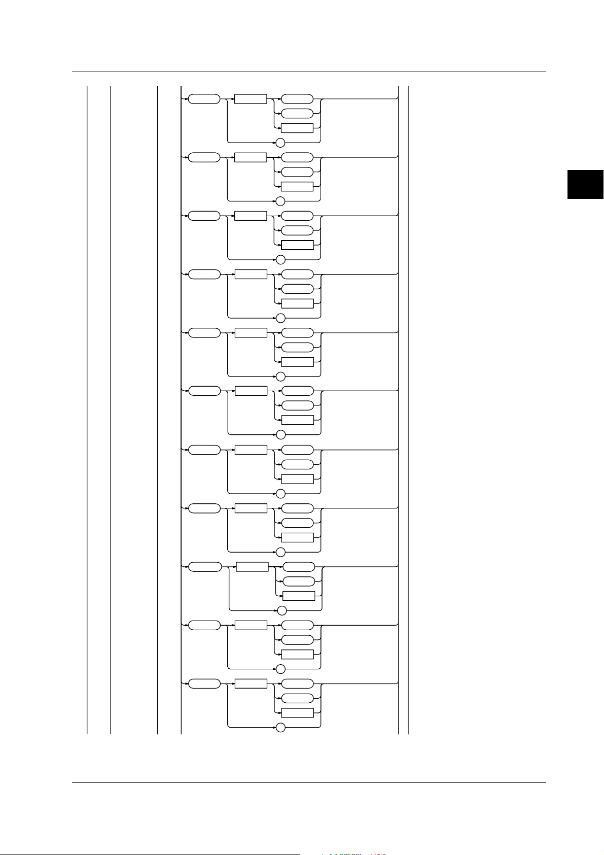
3.3 CALCulation Group
BLOCk <x> : TA Verage ?
WINDow <x> : AVERage ? <Space> ALL
TRF <Space> OFF
ON
<NRf>
?
?
;
TJITter
TMAXimum ?
TMINimum ?
TSDeviation ?
TPTopeak ?
TFLutter ?
TRF ?
TSNumber ?
;
ELERror
?
? <Space> ALL
SELect
SELect
FLUTter
JITTer
MAXimum
MEDian
MELE
MINimum
MODE
PTOPeak
SDEViation
SNUMber
? <Space> ALL
SELect
? <Space> ALL
SELect
? <Space> ALL
SELect
? <Space> ALL
SELect
? <Space> ALL
SELect
? <Space> ALL
SELect
? <Space> ALL
SELect
? <Space> ALL
SELect
? <Space> ALL
SELect
? <Space> ALL
SELect
3-12 IM 704310-12E
Page 33

;
SUMMation : AVERage ?
ELERror ?
FLUTter ?
JITTer ?
MAXimum ?
MEDian ?
MELE ?
MINimum ?
MODE ?
PTOPeak ?
SDEViation ?
SNUMber ?
3.3 CALCulation Group
3
Commands
?
CALCulation?
Function Queries all settings related to statistics.
Syntax :CALCulation?
Example :CALCulation?
→:CALCULATION:AREA MARKER;
POLARITY POSITIVE;CONSTT 100.000E-09;
PARAMETER:AVERAGE 1;ELERROR 1;FLUTTER 1;
JITTER 1;MAXIMUM 1;MEDIAN 1;MELE 1;
MINIMUM 1;MODE 1;PTOPEAK 1;SDEVIATION 1
CALCulation:AREA
Function Sets the area to calculate the statistics or
queries the current setting.
Syntax :CALCulation:AREA {MARKer|WINDow|BLOCk}
Example :CALCULATION:AREA MARKER
:CALCULATION:AREA?
→:CALCULATION:AREA MARKER
CALCulation:AUTot?
Function Queries the measured T value or the estimated
T value for the auto window mode.
Syntax :CALCulation:AUTot?
Example :CALCULATION:AUTOT?
→3.6750E-8
CALCulation[:BLOCk<x>]:TAVerage?
Function Queries the average value during the time
variation display.
Syntax :CALCulation[:BLOCk<x>]:TAVerage?
Example :CALCULATION:BLOCK1:TAVERAGE?
→2.4035E-9
Description • If the statistics are not valid, [NAN] is returned
in response to a query.
• Omit ":BLOCK<x>" if block sampling is not
used.
CALCulation[:BLOCk<x>]:TFLutter?
Function Queries the flutter value (σ/average value)
during the time variation display.
Syntax :CALCulation[:BLOCk<x>]:TFLutter?
Example :CALCULATION:BLOCK1:TFLUTTER?
→1.2887E+1
Description • If the statistics are not valid, [NAN] is returned
in response to a query.
• Omit ":BLOCK<x>" if block sampling is not
used.
CALCulation[:BLOCk<x>]:TJITter?
Function Queries the jitter value (P-P/average value)
during the time variation display.
Syntax :CALCulation[:BLOCk<x>]:TJITter?
Example CALCULATION:BLOCK1:TJITTER?
→1.382E+00
Description • If the statistics are not valid, [NAN] is returned
in response to a query.
• Omit ":BLOCK<x>" if block sampling is not
used.
CALCulation[:BLOCk<x>]:TMAXimum?
Function Queries the maximum value during the time
variation display.
Syntax :CALCulation[:BLOCk<x>]:TMAXimum?
Example :CALCULATION:BLOCK:TMAXIMUM?
→1.1287E-7
Description • If the statistics are not valid, [NAN] is returned
in response to a query.
• Omit ":BLOCK<x>" if block sampling is not
used.
3-13IM 704310-12E
Page 34

3.3 CALCulation Group
CALCulation[:BLOCk<x>]:TMINimum?
Function Queries the minimum value during the time
variation display.
Syntax :CALCulation[:BLOCk<x>]:TMINimum?
Example :CALCULATION:BLOCK1:TMINIMUM?
→9.99437E-8
Description • If the statistics are not valid, [NAN] is returned
in response to a query.
• Omit ":BLOCK<x>" if block sampling is not
used.
CALCulation[:BLOCk<x>]:TPTopeak?
Function Queries the P-P value during the time variation
display.
Syntax :CALCulation[:BLOCk<x>]:TPTopeak?
Example :CALCULATION:BLOCK1:TPTOPEAK?
→3.0245E-9
Description • If the statistics are not valid, [NAN] is returned
in response to a query.
• Omit ":BLOCK<x>" if block sampling is not
used.
CALCulation[:BLOCk<x>]:TRF?
Function Queries the RF value during the time variation
display.
Syntax :CALCulation[:BLOCk<x>]:TRF?
Example :CALCULATION:BLOCK1:TRF?
→1.4775E-1
Description • If the statistics are not valid, [NAN] is returned
in response to a query.
• Omit ":BLOCK<x>" if block sampling is not
used.
CALCulation[:BLOCk<x>]:TSDeviation?
Function Queries the standard deviation (σ) during the
time variation display.
Syntax :CALCulation[:BLOCk<x>]:TSDeviation?
Example :CALCULATION:BLOCK1:TSDEVIATION?
→2.4035E-9
Description • If the statistics are not valid, [NAN] is returned
in response to a query.
• Omit ":BLOCK<x>" if block sampling is not
used.
CALCulation[:BLOCk<x>]:TSNumber?
Function Queries the number of samples on which to
calculate the statistics during the time variation
display.
Syntax :CALCulation[:BLOCk<x>]:TSNumber?
Example :CALCULATION:BLOCK1:TSNUMBER?
→1000
Description • If the statistics are not valid, [NAN] is returned
in response to a query.
• Omit ":BLOCK<x>" if block sampling is not
used.
CALCulation:CONStt
Function Sets the value of the constant T or queries the
current setting.
Syntax :CALCulation:CONStt <Time>
:CALCulation:CONStt?
<Time>=1 ns to 250 ns (in 25 ps steps)
Example :CALCULATION:CONSTT 100ns
:CALCULATION:CONSTT?
→:CALCULATION:CONSTT 100.000E-09
CALCulation:PARameter?
Function Queries the ON/OFF state of each statistical
value.
Syntax :CALCulation:PARameter?
Example :CALCULATION:PARAMETER?
→:CALCULATION:PARAMETER:AVERAGE 1;
ELERROR 1;FLUTTER 1;JITTER 1;MAXIMUM 1;
MEDIAN 1;MELE 1;MINIMUM 1;MODE 1;
PTOPEAK 1;SDEVIATION 1
CALCulation:PARameter:CLEar
Function Turns OFF all statistical values.
Syntax :CALCulation:PARameter:CLEar
Example :CALCULATION:PARAMETER:CLEAR
CALCulation:PARameter:AVERage
Function Turns ON/OFF the calculation of the average
value during the histogram display or queries
the current setting.
Syntax :CALCulation:PARameter:AVERage <Boolean>
:CALCulation:PARameter:AVERage?
Example :CALCULATION:PARAMETER:AVERAGE ON
:CALCULATION:PARAMETER:AVERAGE?
→:CALCULATION:PARAMETER:AVERAGE 1
CALCulation:PARameter:ELERror
Function Turns ON/OFF the calculation of the Effect
Length Error during the histogram display or
queries the current setting.
Syntax :CALCulation:PARameter:ELERror <Boolean>
:CALCulation:PARameter:ELERror?
Example :CALCULATION:PARAMETER:ELERROR ON
:CALCULATION:PARAMETER:ELERROR?
→:CALCULATION:PARAMETER:ELERROR 1
CALCulation:PARameter:FLUTter
Function Turns ON/OFF the calculation of the flutter
value (σ/average value) during the histogram
display or queries the current setting.
Syntax :CALCulation:PARameter:FLUTter <Boolean>
:CALCulation:PARameter:FLUTter?
Example :CALCULATION:PARAMETER:FLUTTER ON
:CALCULATION:PARAMETER:FLUTTER?
→:CALCULATION:PARAMETER:FLUTTER 1
3-14 IM 704310-12E
Page 35

3.3 CALCulation Group
CALCulation:PARameter:JITTer
Function Turns ON/OFF the calculation of the jitter value
(σ/T) during the histogram display or queries
the current setting.
Syntax :CALCulation:PARameter:JITTer <Boolean>
:CALCulation:PARameter:JITTer?
Example :CALCULATION:PARAMETER:JITTER ON
:CALCULATION:PARAMETER:JITTER?
→:CALCULATION:PARAMETER:JITTER 1
CALCulation:PARameter:MAXimum
Function Turns ON/OFF the calculation of the maximum
value during the histogram display or queries
the current setting.
Syntax :CALCulation:PARameter:MAXimum <Boolean>
:CALCulation:PARameter:MAXimum?
Example :CALCULATION:PARAMETER:MAXIMUM ON
:CALCULATION:PARAMETER:MAXIMUM?
→:CALCULATION:PARAMETER:MAXIMUM 1
CALCulation:PARameter:MEDian
Function Turns ON/OFF the calculation of the median
value during the histogram display or queries
the current setting.
Syntax :CALCulation:PARameter:MEDian <Boolean>
:CALCulation:PARameter:MEDian?
Example :CALCULATION:PARAMETER:MEDIAN ON
:CALCULATION:PARAMETER:MEDIAN?
→:CALCULATION:PARAMETER:MEDIAN 1
CALCulation:PARameter:MELE
Function Turns ON/OFF the calculation of the MELE
value during the histogram display or queries
the current setting.
Syntax :CALCulation:PARameter:MELE <Boolean>
:CALCulation:PARameter:MELE?
Example :CALCULATION:PARAMETER:MELE ON
:CALCULATION:PARAMETER:MELE?
→:CALCULATION:PARAMETER:MELE 1
CALCulation:PARameter:MINimum
Function Turns ON/OFF the calculation of the minimum
value during the histogram display or queries
the current setting.
Syntax :CALCulation:PARameter:MINimum <Boolean>
:CALCulation:PARameter:MINimum?
Example :CALCULATION:PARAMETER:MINIMUM ON
:CALCULATION:PARAMETER:MINIMUM?
→:CALCULATION:PARAMETER:MINIMUM 1
CALCulation:PARameter:MODE
Function Turns ON/OFF the calculation of the most
frequent value during the histogram display or
queries the current setting.
Syntax :CALCulation:PARameter:MODE <Boolean>
:CALCulation:PARameter:MODE?
Example :CALCULATION:PARAMETER:MODE ON
:CALCULATION:PARAMETER:MODE?
→:CALCULATION:PARAMETER:MODE 1
CALCulation:PARameter:PTOPeak
Function Turns ON/OFF the calculation of the P-P value
during the histogram display or queries the
current setting.
Syntax :CALCulation:PARameter:PTOPeak <Boolean>
:CALCulation:PARameter:PTOPeak?
Example :CALCULATION:PARAMETER:PTOPEAK ON
:CALCULATION:PARAMETER:PTOPEAK?
→:CALCULATION:PARAMETER:PTOPEAK 1
CALCulation:PARameter:SDEViation
Function Turns ON/OFF the calculation of the standard
deviation (σ) during the histogram display or
queries the current setting.
Syntax :CALCulation:PARameter:SDEViation
<Boolean>
:CALCulation:PARameter:SDEViation?
Example :CALCULATION:PARAMETER:SDEVIATION ON
:CALCULATION:PARAMETER:SDEVIATION?
→:CALCULATION:PARAMETER:SDEVIATION 1
CALCulation:PARameter:TAVerage
Function Turns ON/OFF the calculation of the average
value during the time variation display or
queries the current setting.
Syntax :CALCulation:PARameter:TAVerage
<Boolean>
:CALCulation:PARameter:TAVerage?
Example :CALCULATION:PARAMETER:TAVERAGE ON
:CALCULATION:PARAMETER:TAVERAGE?
→:CALCULATION:PARAMETER:TAVERAGE 1
CALCulation:PARameter:TJITter
Function Turns ON/OFF the calculation of the jitter value
(P-P/average value) during the time variation
display or queries the current setting.
Syntax :CALCulation:PARameter:TJITter <Boolean>
:CALCulation:PARameter:TJITter?
Example :CALCULATION:PARAMETER:TJITTER ON
:CALCULATION:PARAMETER:TJITTER?
→:CALCULATION:PARAMETER:TJITTER 1
3
Commands
3-15IM 704310-12E
Page 36

3.3 CALCulation Group
CALCulation:PARameter:TMAXimum
Function Turns ON/OFF the calculation of the maximum
value during the time variation display or
queries the current setting.
Syntax :CALCulation:PARameter:TMAXimum
<Boolean>
:CALCulation:PARameter:TMAXimum?
Example :CALCULATION:PARAMETER:TMAXIMUM ON
:CALCULATION:PARAMETER:TMAXIMUM?
→:CALCULATION:PARAMETER:TMAXIMUM 1
CALCulation:PARameter:TMINimum
Function Turns ON/OFF the calculation of the minimum
value during the time variation display or
queries the current setting.
Syntax :CALCulation:PARameter:TMINimum
<Boolean>
:CALCulation:PARameter:TMINimum?
Example :CALCULATION:PARAMETER:TMINIMUM ON
:CALCULATION:PARAMETER:TMINIMUM?
→:CALCULATION:PARAMETER:TMINIMUM 1
CALCulation:PARameter:TSDeviation
Function Turns ON/OFF the calculation of the standard
deviation (σ) during the time variation display or
queries the current setting.
Syntax :CALCulation:PARameter:TSDeviation
<Boolean>
:CALCulation:PARameter:TSDeviation?
Example :CALCULATION:PARAMETER:TSDEVIATION ON
:CALCULATION:PARAMETER:TSDEVIATION?
→:CALCULATION:PARAMETER:TSDEVIATION 1
CALCulation:PARameter:TPTopeak
Function Turns ON/OFF the calculation of the P-P value
during the time variation display or queries the
current setting.
Syntax :CALCulation:PARameter:TPTopeak
<Boolean>
:CALCulation:PARameter:TPTopeak?
Example :CALCULATION:PARAMETER:TPTOPEAK ON
:CALCULATION:PARAMETER:TPTOPEAK?
→:CALCULATION:PARAMETER:TPTOPEAK 1
CALCulation:PARameter:TFLutter
Function Turns ON/OFF the calculation of the flutter
value (σ/average value) during the time
variation display or queries the current setting.
Syntax :CALCulation:PARameter:TFLutter
<Boolean>
:CALCulation:PARameter:TFLutter?
Example :CALCULATION:PARAMETER:TFLUTTER ON
:CALCULATION:PARAMETER:TFLUTTER?
→:CALCULATION:PARAMETER:TFLUTTER 1
CALCulation:PARameter:TRF
Function Turns ON/OFF the calculation of the RF value
during the time variation display or queries the
current setting.
Syntax :CALCulation:PARameter:RF <Boolean>
:CALCulation:PARameter:RF?
Example :CALCULATION:PARAMETER:TRF ON
:CALCULATION:PARAMETER:TRF?
→:CALCULATION:PARAMETER:TRF 1
CALCulation:POLarity
Function Sets which polarity to analyze when measuring
both polarities during the pulse width
measurement or queries the current setting.
Syntax :CALCulation:POLarity
{POSitive|NEGative|BOTH}
:CALCulation:POLarity?
Example :CALCULATION:POLARITY POSITIVE
:CALCULATION:POLARITY?
→:CALCULATION:POLARITY POSITIVE
CALCulation:SUMMation:AVERage?
Function Queries the average value when the all
windows are summed during multi-window or
auto window mode.
Syntax :CALCulation:SUMMation:AVERage?
Example :CALCULATION:SUMMATION:AVERAGE?
→2.4035E-9
Description If the statistics are not valid, [NAN] is returned in
response to a query.
CALCulation:SUMMation:ELERror?
Function Queries the Effect Length Error when the all
windows are summed during multi-window or
auto window mode.
Syntax :CALCulation:SUMMation:ELERror?
Example :CALCULATION:SUMMATION:ELERROR?
→1.4425E+1
Description If the statistics are not valid, [NAN] is returned in
response to a query.
CALCulation:SUMMation:FLUTter?
Function Queries the flutter value (σ/average value)
when the all windows are summed during multiwindow or auto window mode.
Syntax :CALCulation:SUMMation:FLUTter?
Example :CALCULATION:SUMMATION:FLUTTER?
→1.2887E+1
Description If the statistics are not valid, [NAN] is returned in
response to a query.
3-16 IM 704310-12E
Page 37

3.3 CALCulation Group
CALCulation:SUMMation:JITTer?
Function Queries the jitter value (σ/T) when the all
windows are summed during multi-window or
auto window mode.
Syntax :CALCulation:SUMMation:JITTer?
Example :CALCULATION:SUMMATION:JITTER?
→1.2366E+1
Description If the statistics are not valid, [NAN] is returned in
response to a query.
CALCulation:SUMMation:MAXimum?
Function Queries the maximum value when the all
windows are summed during multi-window or
auto window mode.
Syntax :CALCulation:SUMMation:MAXimum?
Example :CALCULATION:SUMMATION:MAXIMUM?
→1.1287E-7
Description If the statistics are not valid, [NAN] is returned in
response to a query.
CALCulation:SUMMation:MEDian?
Function Queries the median value when the all windows
are summed during multi-window or auto
window mode.
Syntax :CALCulation:SUMMation:MEDian?
Example :CALCULATION:SUMMATION:MEDIAN?
→1.00145E-7
Description If the statistics are not valid, [NAN] is returned in
response to a query.
CALCulation:SUMMation:MODE?
Function Queries the most frequent value when the all
windows are summed during multi-window or
auto window mode.
Syntax :CALCulation:SUMMation:MODE?
Example :CALCULATION:SUMMATION:MODE?
→1.00025E-7
Description If the statistics are not valid, [NAN] is returned in
response to a query.
CALCulation:SUMMation:PTOPeak?
Function Queries the P-P value when the all windows are
summed during multi-window or auto window
mode.
Syntax :CALCulation:SUMMation:PTOPeak?
Example :CALCULATION:SUMMATION:PTOPEAK?
→3.0245E-9
Description If the statistics are not valid, [NAN] is returned in
response to a query.
CALCulation:SUMMation:SDEViation?
Function Queries the standard deviation (σ) when the all
windows are summed during multi-window or
auto window mode.
Syntax :CALCulation:SUMMation:SDEViation?
Example :CALCULATION:SUMMATION:SDEVIATION?
→2.4035E-9
Description If the statistics are not valid, [NAN] is returned in
response to a query.
3
Commands
CALCulation:SUMMation:MELE?
Function Queries the MELE value when the all windows
are summed during multi-window or auto
window mode.
Syntax :CALCulation:SUMMation:MELE?
Example :CALCULATION:SUMMATION:MELE?
→9.99437E-8
Description If the statistics are not valid, [NAN] is returned in
response to a query.
CALCulation:SUMMation:MINimum?
Function Queries the maximum value when the all
windows are summed during multi-window or
auto window mode.
Syntax :CALCulation:SUMMation:MINimum?
Example :CALCULATION:SUMMATION:MINIMUM?
→9.99437E-8
Description If the statistics are not valid, [NAN] is returned in
response to a query.
CALCulation:SUMMation:SNUMber?
Function Queries the number of samples on which to
calculate the statistics when the all windows are
summed during multi-window or auto window
mode.
Syntax :CALCulation:SUMMation:SNUMber?
Example :CALCULATION:SUMMATION:SNUMBER?
→1000
Description If the statistics are not valid, [NAN] is returned in
response to a query.
CALCulation[:WINDow<x>]:AVERage?
Function Queries the average value during the histogram
display.
Syntax :CALCulation[:WINDow<x>]:AVERage?[{ALL|
SELect}]
Example :CALCULATION:WINDOW1:AVERAGE?ALL
→1.00035E-7
Description • If the statistics are not valid, [NAN] is returned
in response to a query.
• Omit "WINDow<x>" if the window is set to
single mode.
• Omit the data if the inter-symbol interference
analysis function is OFF.
3-17IM 704310-12E
Page 38

3.3 CALCulation Group
CALCulation[:WINDow<x>]:ELERror?
Function Queries the Effect Length Error value during the
histogram display.
Syntax :CALCulation[:WINDow<x>]:ELERror?[{ALL|
SELect}]
Example :CALCULATION:WINDOW1:ELERROR?ALL
→1.4425E+1
Description • If the statistics are not valid, [NAN] is returned
in response to a query.
• Omit "WINDow<x>" if the window is set to
single mode.
• Omit the data if the inter-symbol interference
analysis function is OFF.
CALCulation[:WINDow<x>]:FLUTter?
Function Queries the flutter value (σ/average value)
during the histogram display.
Syntax :CALCulation[:WINDow<x>]:FLUTter?[{ALL|
SELect}]
Example :CALCULATION:WINDOW1:FLUTTER?ALL
→1.2887E+1
Description • If the statistics are not valid, [NAN] is returned
in response to a query.
• Omit "WINDow<x>" if the window is set to
single mode.
• Omit the data if the inter-symbol interference
analysis function is OFF.
CALCulation[:WINDow<x>]:MEDian?
Function Queries the median value during the histogram
display.
Syntax :CALCulation[:WINDow<x>]:MEDian?[{ALL|
SELect}]
Example :CALCULATION:WINDOW1:MEDIAN?ALL
→1.00145E-7
Description • If the statistics are not valid, [NAN] is returned
in response to a query.
• Omit "WINDow<x>" if the window is set to
single mode.
• Omit the data if the inter-symbol interference
analysis function is OFF.
CALCulation[:WINDow<x>]:MELE?
Function Queries the MELE value during the histogram
display.
Syntax :CALCulation[:WINDow<x>]:MELE?[{ALL|
SELect}]
Example :CALCULATION:WINDOW1:MELE?ALL
→9.99437E-8
Description • If the statistics are not valid, [NAN] is returned
in response to a query.
• Omit "WINDow<x>" if the window is set to
single mode.
• Omit the data if the inter-symbol interference
analysis function is OFF.
CALCulation[:WINDow<x>]:JITTer?
Function Queries the jitter value (σ/T) during the
histogram display.
Syntax :CALCulation[:WINDow<x>]:JITTer?[{ALL|
SELect}]
Example :CALCULATION:WINDOW1:JITTER?ALL
→1.2366E+1
Description • If the statistics are not valid, [NAN] is returned
in response to a query.
• Omit "WINDow<x>" if the window is set to
single mode.
• Omit the data if the inter-symbol interference
analysis function is OFF.
CALCulation[:WINDow<x>]:MAXimum?
Function Queries the maximum value during the
histogram display.
Syntax :CALCulation[:WINDow<x>]:MAXimum?[{ALL|
SELect}]
Example :CALCULATION:WINDOW1:MAXIMUM?ALL
→1.1287E-7
Description • If the statistics are not valid, [NAN] is returned
in response to a query.
• Omit "WINDow<x>" if the window is set to
single mode.
• Omit the data if the inter-symbol interference
analysis function is OFF.
CALCulation[:WINDow<x>]:MINimum?
Function Queries the minimum value during the
histogram display.
Syntax :CALCulation[:WINDow<x>]:MINimum?[{ALL|
SELect}]
Example :CALCULATION:WINDOW1:MINIMUM?ALL
→9.99437E-8
Description • If the statistics are not valid, [NAN] is returned
in response to a query.
• Omit "WINDow<x>" if the window is set to
single mode.
• Omit the data if the inter-symbol interference
analysis function is OFF.
CALCulation[:WINDow<x>]:MODE?
Function Queries the most frequent value during the
histogram display.
Syntax :CALCulation[:WINDow<x>]:MODE?[{ALL|
SELect}]
Example :CALCULATION:WINDOW1:MODE?ALL
→1.00025E-7
Description • If the statistics are not valid, [NAN] is returned
in response to a query.
• Omit "WINDow<x>" if the window is set to
single mode.
• Omit the data if the inter-symbol interference
analysis function is OFF.
3-18 IM 704310-12E
Page 39

CALCulation[:WINDow<x>]:PTOPeak?
Function Queries the P-P value during the histogram
display.
Syntax :CALCulation[:WINDow<x>]:PTOPeak?[{ALL|
SELect}]
Example :CALCULATION:WINDOW1:PTOPEAK?ALL
→3.0245E-9
Description • If the statistics are not valid, [NAN] is returned
in response to a query.
• Omit "WINDow<x>" if the window is set to
single mode.
• Omit the data if the inter-symbol interference
analysis function is OFF.
CALCulation[:WINDow<x>]:SDEViation?
Function Queries the standard deviation (σ) during the
histogram display.
Syntax :CALCulation[:WINDow<x>]:SDEViation?
[{ALL|SELect}]
Example :CALCULATION:WINDOW1:SDEVIATION?ALL
→2.4035E-9
Description • If the statistics are not valid, [NAN] is returned
in response to a query.
• Omit "WINDow<x>" if the window is set to
single mode.
• Omit the data if the inter-symbol interference
analysis function is OFF.
3.3 CALCulation Group
3
Commands
CALCulation[:WINDow<x>]:SNUMber?
Function Queries the number of samples on which to
calculate the statistics during the histogram
display.
Syntax :CALCulation[:WINDow<x>]:SNUMber?[{ALL|
SELect}]
Example :CALCULATION:WINDOW1:SNUMBER?ALL
→1000
Description • If the statistics are not valid, [NAN] is returned
in response to a query.
• Omit "WINDow<x>" if the window is set to
single mode.
• Omit the data if the inter-symbol interference
analysis function is OFF.
3-19IM 704310-12E
Page 40

3.4 COMMunicate Group
3.4 COMMunicate Group
The commands in this group deal with the communication.
;
:COMMunicate :
COMMunicate?
Function Queries all settings related to communications.
Syntax :COMMunicate?
Example :COMMUNICATE?
→:COMMUNICATE:HEADER 1;VERBOSE 1
HEADer <Space> OFF
VERBose <Space> OFF
WAIT <Space> <Register>
?
ON
<NRf>
?
ON
<NRf>
?
?
COMMunicate:HEADer
Function Sets whether or not to attach headers to query
responses or queries the current setting.
Syntax :COMMunicate:HEADer <Boolean>
:COMMunicate:HEADer?
Example :COMMUNICATE:HEADER ON
:COMMUNICATE:HEADER?
→:COMMUNICATE:HEADER 1
COMMunicate:VERBose
Function Sets whether or not to use the full or
abbreviated form for query responses or
queries the current setting.
Syntax :COMMunicate:VERBose <Boolean>
:COMMunicate:VERBose?
Example :COMMUNICATE:VERBOSE OFF
:COMMUNICATE:VERBOSE?
→:COMMUNICATE:VERBOSE 0
COMMunicate:WAIT
Function Waits for any of the specified extended events
to occur.
Syntax :COMMunicate:WAIT <Register>
<Register>=0 to 65535
Example :COMMUNICATE:WAIT 65535
COMMunicate:WAIT?
Function Creates a response when any of the specified
extended events occurs.
Syntax :COMMunicate:WAIT?<Register>
<Register>=0 to 65535
Example :COMMUNICATE:WAIT?65535→1
3-20 IM 704310-12E
Page 41

3.5 DISPlay Group
The commands in this group deal with display settings.
;
:DISPlay : ITEM <Space> HISTogram
LIST
STATistic
TVARiation
?
GRAPhsiz e <Space> FULL
HALF
?
OVERlap <Space> OFF
ON
<NRf>
?
STATistic <Space> OFF
ON
<NRf>
?
GRID <Space> OFF
ON
<NRf>
?
DOTConnect <Space> OFF
ON
<NRf>
?
DOTType <Space> PIXel
MARK
?
;
3.5 DISPlay Group
3
Commands
PANorama : STAT e <Space> OFF
ON
<NRf>
?
AREA <Space>
ZOOM : ADJust
SITem <Space> HISTogram
TVARiation
?
<Time>
?
;
POSition <Space>
SPAN <Space>
,
<Time>
<Time>
?
<Time>
?
?
?
3-21IM 704310-12E
Page 42

3.5 DISPlay Group
SSTYle
WINDow
BACKlight
BLOCk
BRIGhtness <Space> <NRf>
<Space>
<Space>
<Space>
<Space> <NRf>
ALL
BLOCk
WINDow
?
ALL
WINDow
SUMMation
?
OFF
ON
<NRf>
?
?
?
?
<x>
DISPlay?
Function Queries all settings related to the display.
Syntax :DISPlay?
Example :DISPLAY?
→:DISPLAY:ITEM HISTOGRAM;GRAPHSIZE
FULL;STATISTIC 1;PANORAMA:STATE 1;
AREA 0.0E-06,0.3E-06;ZOOM:
POSITION 100.000E-09;SPAN 0.3E-06;:
DISPLAY:BRIGHTNESS 1
DISPlay:BACKlight
Function Turns ON/OFF the back light or queries the
current setting.
Syntax :DISPlay:BACKlight <Boolean>
:DISPlay:BACKlight?
Example :DISPLAY:BACKLIGHT ON
:DISPLAY:BACKLIGHT?
→:DISPLAY:BACKLIGHT 1
DISPlay:BRIGhtness
Function Sets the brightness of the screen or queries the
current setting.
Syntax :DISPlay:BRIGhtness <NRf>
:DISPlay:BRIGhtness?
Example :DISPLAY:BRIGHTNESS 1
:DISPLAY:BRIGHTNESS?
→:DISPLAY:BRIGHTNESS 1
DISPlay:DOTConnect
Function Turns ON/OFF the dot connection function
during the time variation display or queries the
current setting.
Syntax :DISPlay:DOTConnect <Boolean>
:DISPlay:DOTConnect?
Example :DISPLAY:DOTCONNECT ON
:DISPLAY:DOTCONNECT?
→:DISPLAY:DOTCONNECT 1
DISPlay:BLOCk
Function Sets the block to be displayed or queries the
current setting.
Syntax :DISPlay:BLOCk <NRf>
:DISPlay:BLOCk?
<NRf>=Block number (1 to number of
blocks)
Example :DISPLAY:BLOCK 1
:DISPLAY:BLOCK?
DISPlay:DOTType
Function Sets the display format of the measurement
point during the time variation display or queries
the current setting.
Syntax :DISPlay:DOTType {PIXel|MARK}
:DISPlay:DOTType?
Example :DISPLAY:DOTTYPE PIXEL
:DISPLAY:DOTTYPE?
→:DISPLAY:DOTTYPE PIXEL
→:DISPLAY:BLOCK 1
Description This command can only be used when the
measurement mode is set to time stamp and
the block sampling function is turned ON.
3-22 IM 704310-12E
Page 43

3.5 DISPlay Group
DISPlay:GRAPhsize
Function Sets the size of the graph display or queries the
current setting.
Syntax :DISPlay:GRAPhsize {FULL|HALF}
:DISPlay:GRAPhsize?
Example :DISPLAY:GRAPHSIZE FULL
:DISPLAY:GRAPHSIZE?
→:DISPLAY:GRAPHSIZE FULL
DISPlay:GRID
Function Turns ON/OFF the grid during the time variation
display or queries the current setting.
Syntax :DISPlay:GRID <Boolean>
:DISPlay:GRID?
Example :DISPLAY:GRID ON
:DISPLAY:GRID?
→:DISPLAY:GRID 1
DISPlay:ITEM
Function Sets the display format or queries the current
setting.
Syntax :DISPlay:ITEM
{HISTogram|LIST|STATistic|TVARiation}
:DISPlay:ITEM?
Example :DISPLAY:ITEM HISTOGRAM
:DISPLAY:ITEM?
→:DISPLAY:ITEM HISTOGRAM
DISPlay:OVERlap
Function Sets whether or not to superimpose the polarity
display (ON/OFF) when measuring both
polarities or slopes.
Syntax :DISPlay:OVERlap <Boolean>
:DISPlay:OVERlap?
Example :DISPLAY:OVERLAP ON
:DISPLAY:OVERLAP?
→:DISPLAY:OVERLAP 1
DISPlay:PANorama?
Function Queries all settings related to the panorama
display.
Syntax :DISPlay:PANorama?
Example :DISPLAY:PANORAMA?
→:DISPLAY:PANORAMA:STATE 1;
AREA 0.0E-06,0.3E-06;ZOOM:
POSITION 100.000E-09;
SPAN 0.3E-06
DISPlay:PANorama:AREA
Function Sets the panorama display range or queries the
current setting.
Syntax :DISPlay:PANorama:AREA <Time>,<Time>
:DISPlay:PANorama:AREA?
Example :DISPLAY:PANORAMA:AREA 0,300ns
:DISPLAY:PANORAMA:AREA?
→:DISPLAY:PANORAMA:AREA 0.0E-06,0.3E-06
DISPlay:PANorama[:STATe]
Function Turns ON/OFF the panorama display or queries
the current setting.
Syntax :DISPlay:PANorama[:STATe] <Boolean>
:DISPlay:PANorama:STATe?
Example :DISPLAY:PANORAMA:STATE ON
:DISPLAY:PANORAMA:STATE?
→:DISPLAY:PANORAMA:STATE 1
DISPlay:PANorama:ZOOM?
Function Queries all settings related to the zoom function
of the panorama display.
Syntax :DISPlay:PANorama:ZOOM?
Example :DISPLAY:PANORAMA:ZOOM?
→:DISPLAY:PANORAMA:ZOOM:
POSITION 100.000E-09;SPAN 0.3E-06
DISPlay:PANorama:ZOOM:ADJust
Function Adjusts the zoom setting of the panorama
display.
Syntax :DISPlay:PANorama:ZOOM:ADJust
Example :DISPLAY:PANORAMA:ZOOM:ADJUST
DISPlay:PANorama:ZOOM:POSition
Function Sets the zoom position of the panorama display
or queries the current setting.
Syntax :DISPlay:PANorama:ZOOM:POSition <Time>
:DISPlay:PANorama:ZOOM:POSition?
Example :DISPLAY:PANORAMA:ZOOM:POSITION 1us
:DISPLAY:PANORAMA:ZOOM:POSITION?
→:DISPLAY:PANORAMA:ZOOM:
POSITION 1.000000E-06
DISPlay:PANorama:ZOOM:SPAN
Function Sets the zoom range of the panorama display
or queries the current setting.
Syntax :DISPlay:PANorama:ZOOM:SPAN <Time>
:DISPlay:PANorama:ZOOM:SPAN?
Example :DISPLAY:PANORAMA:ZOOM:SPAN 300ns
:DISPLAY:PANORAMA:ZOOM:SPAN?
→:DISPLAY:PANORAMA:ZOOM:SPAN 0.3E-06
DISPlay:SITem
Function Sets the type of statistical values to display or
queries the current setting.
Syntax :DISPlay:SITem {HISTogram|TVARiation}
:DISPlay:SITem?
Example :DISPLAY:SITEM HISTOGRAM
:DISPLAY:SITEM?
→:DISPLAY:SITEM HISTOGRAM
3-23IM 704310-12E
3
Commands
Page 44

3.5 DISPlay Group
DISPlay:SSTYle
Function Sets the format of the statistics display or
queries the current setting.
Syntax :DISPlay:SSTYle {ALL|BLOCk|WINDow}
:DISPlay:SSTYle?
Example :DISPLAY:SSTYLE ALL
:DISPLAY:SSTYLE?
→:DISPLAY:SSTYLE ALL
Description ALL or WINDow can be specified when the
measurement mode is hardware histogram and
the window mode is multi-window or auto
window. A query in this condition will return
ALL or WINDow.
ALL or BLOCk can be specified when the
measurement mode is time stamp, the block
sampling function is ON and the statistics of the
time variation are being displayed. A query in
this condition will return ALL or BLOCk.
This command cannot be issued for conditions
other than those specified above.
DISPlay:STATistic
Function Turns ON/OFF the statistics display during the
histogram or time variation display or queries
the current setting.
Syntax :DISPlay:STATistic {<Boolean>}
:DISPlay:STATistic?
Example :DISPLAY:STATISTIC ON
:DISPLAY:STATISTIC?
→:DISPLAY:STATISTIC 1
DISPlay:WINDow
Function Sets the window to display or queries the
current setting.
Syntax :DISPlay:WINDow {ALL|SUMMation|
WINDow<x>}
:DISPlay:WINDow?
<x>=Window number (1 to number of
windows)
Example :DISPLAY:WINDOW ALL
:DISPLAY:WINDOW?
→:DISPLAY:WINDOW ALL
Description This command can be used only when the
measurement mode is set to hardware
histogram and the window is set to multiwindow or auto window.
3-24 IM 704310-12E
Page 45

3.6 FILE Group
The commands in this group deal with file operations.
;
:FILE : FORMat <Space> NORMal , DD64
QUICk
DRIVe <Space> FD0
SCSI , <NRf> , <NRf>
CDIRector y <Space> <String>
MDIRector y <Space> <Filename>
FREE ?
PA TH
LOAD : BINar y <Space> <Filename>
DELete : BINar y <Space> <Filename>
SAVE : ANAMing <Space> OFF
?
;
SETup <Space> <Filename>
;
BMP <Space> <Filename>
TIFF <Space> <Filename>
POSTscript <Space> <Filename>
SETup <Space> <Filename>
STATistic <Space> <Filename>
TEXT <Space> <Filename>
;
COMMent <Space> <String>
BINar y <Space> <Filename>
SETup <Space> <Filename>
STATistic <Space> <Filename>
TEXT <Space> <Filename>
3.6 FILE Group
DD72
HD12
HD14
3
Commands
ON
<NRf>
?
?
?
?
FILE?
Function Queries all settings related to files.
Syntax :FILE?
Example :FILE?
→:FILE:DRIVE FD0;SAVE:ANAMING 1;
COMMENT "SAMPLE"
FILE:CDIRectory
Function Changes the current directory.
Syntax :FILE:CDIRectory <string>
Example :FILE:CDIRECTORY "NO_1"
3-25IM 704310-12E
Page 46

3.6 FILE Group
FILE:DELete:BINary
Function Deletes the binary measurement data file.
Syntax :FILE:DELete:BINary <string>
<string>="filename" (8 characters or
less, see User’s Manual for
TA520)
Example :FILE:DELETE:BINARY "TRASH"
FILE:DELete:BMP
Function BMP Deletes the screen image file.
Syntax :FILE:DELete:BMP <string>
<string>="filename" (8 characters or
less, see User’s Manual for
TA520)
Example :FILE:DELETE:BINARY "TRASH"
FILE:DELete:POSTscript
Function Deletes the post script screen image file.
Syntax :FILE:DELete:POSTscript <string>
<string>="filename" (8 characters or
less, see User’s Manual for
TA520)
Example :FILE:DELETE:POSTSCRIPT "TRASH"
FILE:DELete:SETup
Function Deletes the setup information data file.
Syntax :FILE:DELete:SETup <string>
<string>="filename" (8 characters or
less, see User’s Manual for
TA520)
Example :FILE:DELETE:SETUP "TRASH"
FILE:DELete:STATistic
Function Deletes the statistics data file.
Syntax :FILE:DELete:STATistic <string>
<string>="filename" (8 characters or
less, see User’s Manual for
TA520)
Example :FILE:DELETE:STATISTIC "TRASH"
FILE:DELete:TIFF
Function Deletes the TIFF screen image file.
Syntax :FILE:DELete:TIFF <string>
<string>="filename" (8 characters or
less, see User’s Manual for
TA520)
Example :FILE:DELETE:TIFF "TRASH"
FILE:DELete:TEXT
Function Deletes the text measurement data file.
Syntax :FILE:DELete:TEXT <string>
<string>="filename" (8 characters or
less, see User’s Manual for
TA520)
Example :FILE:DELETE:TEXT "TRASH"
FILE:DRIVe
Function Sets the drive.
Syntax :FILE:DRIVe {FD0|SCSI,<NRf>[,<NRf>]}
First <NRf>=SCSI address (0 to 7),
second <NRf>=partition (1 to 5)
Example :FILE:DRIVE FD0
Description Omit the second <NRf> when the drive has no
partitions set.
FILE:FORMat
Function Formats the floppy disk.
Syntax :FILE:FORMat {NORMal,(DD64|DD72|HD12|
HD14)|QUICk}
Example FILE:FORMAT NORMAL,HD14
FILE:FREE?
Function Queries the drive free space in number of
bytes.
Syntax :FILE:FREE?
Example :FILE:FREE?
→163840
FILE:LOAD:BINary
Function Loads the binary measurement data.
Syntax :FILE:LOAD:BINary <string>
<string>="filename" (8 characters or
less, see User’s Manual for
TA520)
Example :FILE:LOAD:BINARY "TARGET"
FILE:LOAD:SETup
Function Loads the setup information data.
Syntax :FILE:LOAD:SETup <string>
<string>="filename" (8 characters or
less, see User’s Manual for
TA520)
Example :FILE:LOAD:SETUP "TARGET"
FILE:MDIRectory
Function Creates a directory.
Syntax :FILE:MDIRectory <string>
<string>="dirctory_name" (8 characters
or less, see User’s Manual for
TA520)
Example :FILE:MDIRECTORY "NEW"
FILE:PATH?
Function Queries the current directory.
Syntax :FILE:PATH <string>
:FILE:PATH?
Example :FILE:PATH?
→"_USER1"
3-26 IM 704310-12E
Page 47

3.6 FILE Group
FILE:SAVE?
Function Queries all settings related to saving the file.
Syntax :FILE:SAVE?
Example :FILE:SAVE?
→:FILE:SAVE:ANAMING 0;COMMENT "SAMPLE"
FILE:SAVE:ANAMing
Function Turns ON/OFF the auto naming function for
saving files or queries the current setting.
Syntax :FILE:SAVE:ANAMing <Boolean>
:FILE:SAVE:ANAMing?
Example :FILE:SAVE:ANAMING ON
:FILE:SAVE:ANAMING?
→:FILE:SAVE:ANAMING 1
FILE:SAVE:BINary
Function Saves the measured data in binary format.
Syntax :FILE:SAVE:BINary <string>
<string>="filename" (8 characters or
less, see User’s Manual for
TA520)
Example :FILE:SAVE:BINARY "TARGET"
FILE:SAVE:COMMent
Function Sets a comment in the top left corner of the
screen or queries the current setting.
Syntax :FILE:SAVE:COMMent <string>
:FILE:SAVE:COMMent?
<string>="comment" (25 characters or
less, see the User’s Manual for
TA520)
Example :FILE:SAVE:COMMENT "SAMPLE"
:FILE:SAVE:COMMENT?
→:FILE:SAVE:COMMENT "SAMPLE"
FILE:SAVE:TEXT
Function Saves the measured data in text format.
Syntax :FILE:SAVE:TEXT <string>
<string>="filename" (8 characters or
less, see User’s Manual for
TA520)
Example :FILE:SAVE:TEXT "TARGET"
3
Commands
FILE:SAVE:SETup
Function Saves the setup information data.
Syntax :FILE:SAVE:SETup <string>
<string>="filename" (8 characters or
less, see User’s Manual for
TA520)
Example :FILE:SAVE:SETUP "TARGET"
FILE:SAVE:STATistic
Function Saves the statistical data.
Syntax :FILE:SAVE:STATistic <string>
<string>="filename" (8 characters or
less, see User’s Manual for
TA520)
Example :FILE:SAVE:STATISTIC "TARGET"
3-27IM 704310-12E
Page 48

3.7 HCOPy Group
3.7 HCOPy Group
The commands in this group deal with the output of screen image data.
;
:HCOPy :
EXECute
DEVice <Space> PRINter
MEDia
?
FORMat <Space> BMP
TIFF
POSTscript
?
COMPression <Space> OFF
ON
<NRf>
?
TONE <Space> BW
GRAY
COLor
RCOLor
?
FILename <Space> <Filename>
?
ANAMing <Space> OFF
ON
<NRf>
?
COMMent <Space> <String>
?
ABORt
?
HCOPy?
Function Queries all settings related to the output of the
screen image data.
Syntax :HCOPy?
Example :HCOPY?
→:HCOPY:DEVICE PRINTER;COMMENT "SAMPLE"
HCOPy:ANAMing
Function Turns ON/OFF the auto naming function for
saving the screen image to files or queries the
current setting.
Syntax :HCOPy:ANAMing <Boolean>
:HCOPy:ANAMing?
Example :HCOPY:ANAMING ON
HCOPy:ABORt
Function Aborts the hard copy.
:HCOPY:ANAMING?
→:HCOPY:ANAMING 1
Syntax :HCOPy:ABORt
Example :HCOPY:ABORT
3-28 IM 704310-12E
Page 49

3.7 HCOPy Group
HCOPy:COMMent
Function Sets a comment in the top left corner of the
screen or queries the current setting.
Syntax :HCOPy:COMMent <string>
:HCOPy:COMMent?
<string>="comment" (25 characters or
less, see the User’s Manual for
TA520)
Example :HCOPY:COMMENT "SAMPLE"
:HCOPY:COMMENT?
→:HCOPY:COMMENT "SAMPLE"
HCOPy:COMPression
Function Turns ON/OFF the compression when saving
the screen image in BMP or TIFF format or
queries the current setting.
Syntax :HCOPy:COMPression <Boolean>
:HCOPy:COMPression?
Example :HCOPY:COMPRESSION ON
:HCOPY:COMPRESSION?
→:HCOPY:COMPRESSION 1
HCOPy:DEVice
Function Sets the output destination of the screen image
or queries the current setting.
Syntax :HCOPy:DEVice {PRINter|MEDia}
:HCOPy:DEVice?
Example :HCOPY:DEVICE PRINTER
:HCOPY:DEVICE?
→:HCOPY:DEVICE PRINTER
HCOPy:TONE
Function Sets the color for saving the screen image or
queries the current setting.
Syntax :HCOPy:TONE {BW|GRAY|COLor|RCOLor}
Example :HCOPY:TONE BW
:HCOPY:TONE?
→:HCOPY:TONE BW
3
Commands
HCOPy[:EXECute]
Function Executes a hard copy of the screen image.
Syntax :HCOPy[:EXECute]
Example :HCOPY:EXECUTE
HCOPy:FILename
Function Sets the name of the file in which to save the
screen image or queries the current setting.
Syntax :HCOPy:FILename <string>
:HCOPy:FILename?
<string>="filename" (8 characters or
less, see User’s Manual for
TA520)
Example :HCOPY:FILENAME "KEEP"
:HCOPY:FILENAME?
→:HCOPY:FILENAME "KEEP"
HCOPy:FORMat
Function Sets the format of the file in which to save the
screen image or queries the current setting.
Syntax :HCOPy:FORMat {BMP|TIFF|POSTscript}
Example :HCOPY:FORMAT BMP
:HCOPY:FORMAT?
→:HCOPY:FORMAT BMP
3-29IM 704310-12E
Page 50

3.8 HHIStogram Group
3.8 HHIStogram Group
The commands in this group deal with the histogram settings of the hardware histogram mode.
;
:HHIStogram : MODE <Space> SINGle
MULTi
AUTO
?
;
VERTical : AXIS <Space> LINear
LOGarithmic
?
HIGH <Space> <NRf>
?
?
;
MARKer : STAT e <Space> OFF
ON
<NRf>
?
LOW <Space> <NRf>
?
?
;
SINGle : TVALue <Space>
HORizontal : CENTer <Space>
MARKer : LEFT <Space>
<Time>
?
;
SPAN <Space>
;
RIGHt <Space>
LV ALue ?
RVALue ?
?
?
<Time>
?
<Time>
?
?
<Time>
?
<Time>
?
3-30 IM 704310-12E
Page 51

;
AUTO : MODulation <Space> EFM
EFMPlus
M1TO7
?
TTYPe <Space> MEASured
ESTimated
?
?
;
MULTi : SIZE <Space> <NRf>
?
UPDate
TVALue <Space>
WINDow <x> : LABel <Space> <NRf>
<Time>
?
;
?
;
HORizontal : CENTer <Space>
SPAN <Space>
;
MARKer : LEFT <Space>
RIGHt <Space>
LV ALue ?
RVALue ?
?
?
?
?
3.8 HHIStogram Group
3
Commands
<Time>
?
<Time>
?
?
<Time>
?
<Time>
?
HHIStogram?
Function Queries all settings related to the histogram
display during the hardware histogram mode.
Syntax :HHIStogram?
Example :HHISTOGRAM?
→:HHISTOGRAM:MODE SINGLE;VERTICAL:
AXIS LINEAR;HIGH1.0E+03;:HHISTOGRAM:
MARKER:STATE 1;LOW 0.1E+03;:HHISTOGRAM:
SINGLE:TVALUE 100.000E-09;HORIZONTAL:
CENTER 150.000E-06;SPAN 0.3E-6;:
HHISTOGRAM:SINGLE:MARKER:
LEFT 100.000E-09;RIGHT 200.000E-09
HHIStogram:AUTO?
Function Queries all settings related to the auto window
mode.
Syntax :HHIStogram:AUTO?
Example :HHISTOGRAM:AUTO?
→:HHISTOGRAM:AUTO:MODULATION EFM
HHIStogram:AUTO:MODulation
Function Sets the modulation method during auto
window mode or queries the current setting.
Syntax :HHIStogram:AUTO:MODulation
{EFM|EFMPlus|M1TO7}
:HHIStogram:AUTO:MODulation?
Example :HHISTOGRAM:AUTO:MODULATION EFM
:HHISTOGRAM:AUTO:MODULATION?
→:HHISTOGRAM:AUTO:MODULATION EFM
3-31IM 704310-12E
Page 52

3.8 HHIStogram Group
HHIStogram:AUTO:TTYPe
Function Sets how the constant T is determined during
the auto window mode or queries the current
setting.
Syntax :HHIStogram:AUTO:TTYPe {MEASured|
ESTimated}
:HHIStogram:AUTO:TTYPe?
Example :HHISTOGRAM:AUTO:TTYPE MEASURED
:HHIStogram:AUTO:TTYPe?
→:HHISTOGRAM:AUTO:TTYPE MEASURED
HHIStogram:MARKer?
Function Queries all settings related to the marker.
Syntax :HHIStogram:MARKer?
Example :HHISTOGRAM:MARKER?
→:HHISTOGRAM:MARKER:STATE 1;LOW 0.1E+03
HHIStogram:MARKer:LOW
Function Sets the position of the low marker or queries
the current setting.
Syntax :HHIStogram:MARKer:LOW <NRf>
:HHIStogram:MARKer:LOW?
<NRf>=Frequency
Example :HHISTOGRAM:MARKER:LOW 100
:HHISTOGRAM:MARKER:LOW?
→:HHISTOGRAM:MARKER:LOW 0.1E+03
HHIStogram:MARKer[:STATe]
Function Turns ON/OFF the markers or queries the
current setting.
Syntax :HHIStogram:MARKer[:STATe] <Boolean>
:HHIStogram:MARKer:STATe?
Example :HHISTOGRAM:MARKER:STATE ON
:HHISTOGRAM:MARKER:STATE?
→:HHISTOGRAM:MARKER:STATE 1
HHIStogram:MODE
Function Sets the mode or queries the current setting.
Syntax :HHIStogram[:MODE] {SINGle|MULTi|AUTO}
:HHIStogram:MODE?
Example :HHISTOGRAM:MODE SINGLE
:HHISTOGRAM:MODE?
→:HHISTOGRAM:MODE SINGLE
HHIStogram:MULTi:SIZE
Function Sets the number of windows or queries the
current setting.
Syntax :HHIStogram:MULTi:SIZE <NRf>
:HHIStogram:MULTi:SIZE?
Example :HHISTOGRAM:MULTI:SIZE 10
:HHISTOGRAM:MULTI:SIZE?
→:HHISTOGRAM:MULTI:SIZE 10
HHIStogram:MULTi:TVALue
Function Sets the value of the constant T or queries the
current setting.
Syntax :HHIStogram:MULTi:TVALue <Time>
:HHIStogram:MULTi:TVALue?
<Time>=1 ns to 250 ns(in 25 ps steps)
Example :HHISTOGRAM:MULTI:TVALUE 100ns
:HHISTOGRAM:MULTI:TVALUE?
→:HHISTOGRAM:MULTI:TVALUE 100.000E-09
HHIStogram:MULTi:UPDate
Function Changes the window setting based on the value
of the constant T.
Syntax :HHIStogram:MULTi:UPDate
Example :HHISTOGRAM:MULTI:UPDATE
HHIStogram:MULTi:WINDow<x>?
Function Queries all settings related to each window.
Syntax :HHIStogram:MULTi:WINDow<x>?
Example :HHISTOGRAM:MULTI:WINDOW1?
→:HHISTOGRAM:MULTI:WINDOW1:LABEL 3;
HORIZONTAL:CENTER 150.000E-09;
SPAN 0.3E-06;:HHISTOGRAM:MULTI:WINDOW1:
MARKER:LEFT 100.000E-09;
RIGHT 200.000E-09
HHIStogram:MULTi:WINDow<x>:HORizontal?
Function Queries all settings related to the horizontal
axis of each window.
Syntax :HHIStogram:MULTi:WINDow<x>:HORizontal?
Examle :HHISTOGRAM:MULTI:WINDOW1:HORIZONTAL?
→:HHISTOGRAM:MULTI:WINDOW1:HORIZONTAL:
CENTER 150.000E-09;SPAN 0.3E-06
HHIStogram:MULTi?
Function Queries all settings related to the multi-window
mode.
Syntax :HHIStogram:MULTi?
Example :HHISTOGRAM:MULTI?
→:HHISTOGRAM:MULTI:SIZE 1;
TVALUE 100.000E-09;WINDOW1:LABEL 3;
HORIZONTAL:CENTER 150.000E-09;
SPAN 0.3E-06;:HHISTOGRAM:MULTI:WINDOW1:
MARKER:LEFT 100.000E-09;
RIGHT 200.000E-09
3-32 IM 704310-12E
Page 53

3.8 HHIStogram Group
HHIStogram:MULTi:WINDow<x>:HORizontal:
CENTer
Function Sets the center position of the horizontal axis of
each window or queries the current setting.
Syntax :HHIStogram:WINDow<x>:HORizontal:
CENTer <Time>
:HHIStogram:WINDow<x>:HORizontal:CENTer?
<Time>=-50 ns to 3.2 µs (in 25 ps steps)
Example :HHISTOGRAM:MULTI:WINDOW1:HORIZONTAL:
CENTER 150ns
:HHISTOGRAM:MULTI:WINDOW1:HORIZONTAL:
CENTER?
→:HHISTOGRAM:MULTI:WINDOW1:
HORIZONTAL:CENTER 150.000E-09
HHIStogram:MULTi:WINDow<x>:HORizontal:
SPAN
Function Sets the width of the horizontal axis of each
window or queries the current setting.
Syntax :HHIStogram:MULTi:WINDow<x>:HORizontal:
SPAN <Time>
:HHIStogram:MULTi:WINDow<x>:HORizontal:
SPAN?
<Time>=1.5 ns,3 ns,7.5 ns,15 ns,30 ns,60
ns,150 ns,300 ns,600 ns,1.5 µs,3
µs,6 µs
Example :HHISTOGRAM:MULTI:WINDOW1:HORIZONTAL:
SPAN 300ns
:HHISTOGRAM:MULTI:WINDOW1:HORIZONTAL:
SPAN?
→:HHISTOGRAM:MULTI:WINDOW1:
HORIZONTAL:SPAN 0.3E-06
HHIStogram:MULTi:WINDow<x>:LABel
Function Sets the label of each window or queries the
current setting.
Syntax :HHIStogram:MULTi:WINDow<x>:LABel <NRf>
:HHIStogram:MULTi:WINDow<x>:LABel?
<NRf>=1 to 32
Example :HHISTOGRAM:MULTI:WINDOW1:LABEL 3
:HHISTOGRAM:MULTI:WINDOW1:LABEL?
→:HHISTOGRAM:MULTI:WINDOW1:LABEL 3
HHIStogram:MULTi:WINDow<x>:MARKer?
Function Queries all settings related to the horizontal
axis marker of each window.
Syntax :HHIStogram:MULTi:WINDow<x>:MARKer?
Example :HHISTOGRAM:MULTI:WINDOW1:MARKER?
→:HHISTOGRAM:MULTI:WINDOW1:MARKER:
LEFT 100.000E-09;RIGHT 200.000E-09
HHIStogram:MULTi:WINDow<x>:MARKer:LEFT
Function Sets the position of the left marker of each
window or queries the current setting.
Syntax :HHIStogram:MULTi:WINDow<x>:MARKer:
LEFT <Time>
:HHIStogram:MULTi:WINDow<x>:MARKer:LEFT?
<Time>=marker position (in 25 ps steps)
Example :HHISTOGRAM:MULTI:WINDOW1:MARKER:
LEFT 100ns
:HHISTOGRAM:MULTI:WINDOW1:MARKER:LEFT?
→:HHISTOGRAM:MULTI:WINDOW1:MARKER:
LEFT 100.000E-09
HHIStogram:MULTi:WINDow<x>:MARKer:LVALue?
Function Queries the frequency at the position of the left
marker.
Syntax :HHIStogram:WINDow<x>:MARKer:LVALue?
Example :HHISTOGRAM:WINDOW1:MARKER:LVALUE?
→1.234E+03
HHIStogram:MULTi:WINDow<x>:MARKer:RIGHt
Function Sets the position of the right marker of each
window or queries the current setting.
Syntax :HHIStogram:MULTi:WINDow<x>:MARKer:
RIGHt <Time>
:HHIStogram:MULTi:WINDow<x>:MARKer:
RIGHt?
<Time>=marker position (in 25 ps steps)
Example :HHISTOGRAM:MULTI:WINDOW1:MARKER:
RIGHT 200ns
:HHISTOGRAM:MULTI:WINDOW1:MARKER:RIGHT?
→:HHISTOGRAM:MULTI:WINDOW1:MARKER:
RIGHT 200.000E-09
HHIStogram:MULTi:WINDow<x>:MARKer:
RVALue?
Function Queries the frequency at the position of the
right marker.
Syntax :HHIStogram:WINDow<x>:MARKer:RVALue?
Example :HHISTOGRAM:WINDOW1:MARKER:RVALUE?
→1.234E+03
HHIStogram:SINGle?
Function Queries all settings related to single window.
Syntax :HHIStogram:SINGle?
Example :HHISTOGRAM:SINGLE?
→:HHISTOGRAM:SINGLE:TVALUE 100.000E-09;
HORIZONTAL:CENTER 150.000E-06;
SPAN 0.3E-6;:HHISTOGRAM:SINGLE:MARKER:
LEFT 100.000E-09;RIGHT 200.000E-09
3
Commands
3-33IM 704310-12E
Page 54

3.8 HHIStogram Group
HHIStogram:SINGle:HORizontal?
Function Queries all settings related to the horizontal
axis of the single window.
Syntax :HHIStogram:SINGle:HORizontal?
Example :HHISTOGRAM:SINGLE:HORIZONTAL?
→:HHISTOGRAM:SINGLE:HORIZONTAL:
CENTER 150.000E-06;SPAN 0.3E-6
HHIStogram:SINGle:HORizontal:CENTer
Function Sets the center position of the hrizontal axis of
the window or queries the current setting.
Syntax :HHIStogram:SINGle:HORizontal:
CENTer <Time>
:HHIStogram:SINGle:HORizontal:CENTer?
<Time>=-50 ns to 3.2 µs (in 25 ps steps)
Example :HHISTOGRAM:SINGLE:HORIZONTAL:
CENTER 150ns
:HHISTOGRAM:SINGLE:HORIZONTAL:CENTER?
→:HHISTOGRAM:SINGLE:HORIZONTAL:
CENTER 150.000E-09
HHIStogram:SINGle:HORizontal:SPAN
Function Sets the width of the horizontal axis of the
window or queries the current setting.
Syntax :HHIStogram:SINGle:HORizontal:
SPAN <Time>
:HHIStogram:SINGle:HORizontal:SPAN?
<Time>=1.5 ns,3 ns,7.5 ns,15 ns,30 ns,60
ns,150 ns,300 ns,600 ns,1.5 µs,3
µs,6 µs
Example :HHISTOGRAM:SINGLE:HORIZONTAL:SPAN 300ns
:HHISTOGRAM:SINGLE:HORIZONTAL:SPAN?
→:HHISTOGRAM:SINGLE:HORIZONTAL:
SPAN 0.3E-06
HHIStogram:SINGle:MARKer:LVALue?
Function Queries the frequency at the position of the left
marker.
Syntax :HHIStogram:SINGle:MARKer:LVALue?
Example :HHISTOGRAM:SINGLE:MARKER:LVALUE?
→1.234E+03
HHIStogram:SINGle:MARKer:RIGHt
Function Sets the position of the right marker or queries
the current setting.
Syntax :HHIStogram:SINGle:MARKer:RIGHt <Time>
:HHIStogram:SINGle:MARKer:RIGHt?
<Time>=marker position (in 25 ps steps)
Example :HHISTOGRAM:SINGLE:MARKER:RIGHT 200ns
:HHISTOGRAM:SINGLE:MARKER:RIGHT?
→:HHISTOGRAM:SINGLE:MARKER:
RIGHT 200.000E-09
HHIStogram:SINGle:MARKer:RVALue?
Function Queries the frequency at the position of the
right marker.
Syntax :HHIStogram:SINGle:MARKer:RVALue?
Example :HHISTOGRAM:SINGLE:MARKER:RVALUE?
→1.234E+03
HHIStogram:SINGle:TVALue
Function Sets the value of the constant T or queries the
current setting.
Syntax :HHIStogram:SINGle:TVALue <Time>
:HHIStogram:SINGle:TVALue?
<Time>=1 ns to 250 ns (in 25 ps steps)
Example :HHISTOGRAM:SINGLE:TVALUE 100ns
:HHISTOGRAM:SINGLE:TVALUE?
→:HHISTOGRAM:SINGLE:TVALUE 100.000E-09
HHIStogram:SINGle:MARKer?
Function Queries all settings related to the horizontal
axis marker.
Syntax :HHIStogram:SINGle:MARKer?
Example :HHISTOGRAM:SINGLE:MARKER?
→:HHISTOGRAM:SINGLE:MARKER:
LEFT 100.000E-09;RIGHT 200.000E-09
HHIStogram:SINGle:MARKer:LEFT
Function Queries all settings related to the horizontal
axis marker.
Syntax :HHIStogram:SINGle:MARKer:LEFT <Time>
:HHIStogram:SINGle:MARKer:LEFT?
<Time>=marker position (in 25 ps steps)
Example :HHISTOGRAM:SINGLE:MARKER:LEFT 100ns
:HHISTOGRAM:SINGLE:MARKER:LEFT?
→:HHISTOGRAM:SINGLE:MARKER:
LEFT 100.000E-09
HHIStogram:VERTical?
Function Queries all settings related to the vertical axis
during the hardware histogram mode.
Syntax :HHIStogram:VERTical?
Example :HHISTOGRAM:VERTICAL?
→:HHISTOGRAM:VERTICAL:AXIS LINEAR;
HIGH 1.0E+03
HHIStogram:VERTical:AXIS
Function Sets the type of vertical axis scale or queries
the current setting.
Syntax :HHIStogram:VERTical:AXIS {LINear|
LOGarithmic}
:HHIStogram:VERTical:AXIS?
Example :HHISTOGRAM:VERTICAL:AXIS LINEAR
:HHISTOGRAM:VERTICAL:AXIS?
→:HHISTOGRAM:VERTICAL:AXIS LINEAR
3-34 IM 704310-12E
Page 55

HHIStogram:VERTical:HIGH
Function Sets the upper limit of the vertical axis scale or
queries the current setting.
Syntax :HHIStogram:VERTical:HIGH <NRf>
:HHIStogram:VERTical:HIGH?
<NRf>=Upper frequency limit
For linear scale
10,20,40,100,200,400,1000,…..,1000000,
1E+7,1E+8,1E+9
For logarithmic scale
1E+1,1E+2,…..,1E+9
Example :HHISTOGRAM:VERTICAL:HIGH 1000
:HHISTOGRAM:VERTICAL:HIGH?
→:HHISTOGRAM:VERTICAL:HIGH 1.0E+03
3.8 HHIStogram Group
3
Commands
3-35IM 704310-12E
Page 56

3.9 INPut Group
3.9 INPut Group
The commands in this group deal with the input section.
;
;
:INPut : ACHannel : IMPedance <Space> I50
COUPling <Space> AC
TRIGg er : MODE <Space> MANual
;
BCHannel : IMPedance <Space> I50
COUPling <Space> AC
TRIGg er : MODE <Space> MANual
;
AGAT e : LEVel <Space> ZERO
I1M
?
DC
?
;
LEVel <Space>
I1M
?
DC
?
;
LEVel <Space>
TTL
TTL10
?
?
SINGleauto
REPeatauto
?
<Voltage>
?
?
?
SINGleauto
REPeatauto
?
<Voltage>
?
?
?
3-36 IM 704310-12E
Page 57

;
INHibit : LEVel <Space> ZERO
TTL
TTL10
?
?
?
3.9 INPut Group
3
Commands
INPut?
Function Queries all settings related to the input section.
Syntax :INPut?
Example :INPUT?
→:INPUT:ACHANNEL:IMPEDANCE I1M;
COUPLING DC;TRIGGER:MODE MANUAL;
LEVEL 2.500E+00;:INPUT:BCHANNEL:
IMPEDANCE I1M;COUPLING DC;TRIGGER:
MODE MANUAL;LEVEL 2.500E+00;:INPUT:
AGATE:LEVEL ZERO;:INPUT:INHIBIT ZERO
INPut:ACHannel?
Function Queries all settings related to channel A.
Syntax :INPut:ACHannel?
Example :INPUT:ACHANNEL?
→:INPUT:ACHANNEL:IMPEDANCE I1M;
COUPLING DC;TRIGGER:MODE MANUAL;
LEVEL 2.500E+00
INPut:ACHannel:COUPling
Function Sets the coupling of channel A or queries the
current setting.
Syntax :INPut:ACHannel:COUPling {AC|DC}
:INPut:ACHannel:COUPling?
Example :INPUT:ACHANNEL:COUPLING DC
:INPUT:ACHANNEL:COUPLING?
→:INPUT:ACHANNEL:COUPLING DC
INPut:ACHannel:IMPedance
Function Sets the input impedance of channel A or
queries the current setting.
Syntax :INPut:ACHannel:IMPedance {I50|I1M}
:INPut:ACHannel:IMPedance?
Example :INPUT:ACHANNEL:IMPEDANCE I1M
:INPUT:ACHANNEL:IMPEDANCE?
→:INPUT:ACHANNEL:IMPEDANCE I1M
INPut:ACHannel:TRIGger?
Function Queries all settings related to the trigger of
channel A.
Syntax :INPut:ACHannel:TRIGger?
Example :INPUT:ACHANNEL:TRIGGER?
→:INPUT:ACHANNEL:TRIGGER:MODE MANUAL;
LEVEL 2.500E+00
INPut:ACHannel:TRIGger:LEVel
Function Sets the trigger level of channel A or queries
the current setting.
Syntax :INPut:ACHannel:TRIGger:LEVel <voltage>
:INPut:ACHannel:TRIGger:LEVel?
During trigger manual mode
<level>=-5V to +5V (in 1 mV steps)
During trigger signal/repeat auto
<level>=0 to 100% (in 1% steps)
Example :INPUT:ACHANNEL:TRIGGER:LEVEL 2.5V
:INPUT:ACHANNEL:TRIGGER:LEVEL?
→:INPUT:ACHANNEL:TRIGGER:
LEVEL 2.500E+00
INPut:ACHannel:TRIGger:MODE
Function Sets the trigger mode of channel A or queries
the current setting.
Syntax :INPut:ACHannel:TRIGger:MODE
{MANual|SINGleauto|REPeatauto}
:INPut:ACHannel:TRIGger:MODE?
Example :INPUT:ACHANNEL:TRIGGER:MODE MANUAL
:INPUT:ACHANNEL:TRIGGER:MODE?
→:INPUT:ACHANNEL:TRIGGER:MODE MANUAL
INPut:AGATe?
Function Queries all settings related to arming and the
external gate.
Syntax :INPut:AGATe?
Example :INPUT:AGATE?
→:INPUT:AGATE:LEVEL ZERO
Description Since the external arming signal input terminal
is shared with the external gate input terminal,
the settings apply to both.
INPut:AGATe:LEVel
Function Sets the arming or gate level or queries the
current setting.
Syntax :INPut:AGATe:LEVel {ZERO|TTL|TTL10}
:INPut:AGATe:LEVel?
Example :INPUT:AGATE:LEVEL ZERO
:INPUT:AGATE:LEVEL?
→:INPUT:AGATE:LEVEL ZERO
3-37IM 704310-12E
Page 58

3.9 INPut Group
INPut:BCHannel?
Function Queries all settings related to channel B.
Syntax :INPut:BCHannel?
Example :INPUT:BCHANNEL?
→:INPUT:BCHANNEL:IMPEDANCE I1M;
COUPLING DC;TRIGGER:MODE MANUAL;
LEVEL 2.500E+00
INPut:BCHannel:COUPling
Function Sets the coupling of channel B or queries the
current setting.
Syntax :INPut:BCHannel:COUPling {AC|DC}
:INPut:BCHannel:COUPling?
Example :INPUT:BCHANNEL:COUPLING DC
:INPUT:BCHANNEL:COUPLING?
→:INPUT:BCHANNEL:COUPLING DC
INPut:BCHannel:IMPedance
Function Sets the input impedance of channel B or
queries the current setting.
Syntax :INPut:BCHannel:IMPedance {I50|I1M}
:INPut:BCHannel:IMPedance?
Example :INPUT:BCHANNEL:IMPEDANCE I1M
:INPUT:BCHANNEL:IMPEDANCE?
→:INPUT:BCHANNEL:IMPEDANCE I1M
INPut:BCHannel:TRIGger:MODE
Function Sets the trigger mode of channel B or queries
the current setting.
Syntax :INPut:BCHannel:TRIGger:MODE {MANual|
SINGleauto|REPeatauto}
:INPut:BCHannel:TRIGger:MODE?
Example :INPUT:BCHANNEL:TRIGGER:MODE MANUAL
:INPUT:BCHANNEL:TRIGGER:MODE?
→:INPUT:BCHANNEL:TRIGGER:MODE MANUAL
INPut:INHibit?
Function Queries all settings related to the inhibit
function.
Syntax :INPut:INHibit?
Example :INPUT:INHIBIT?
→:INPUT:INHIBIT:LEVEL ZERO
INPut:INHibit:LEVel
Function Sets the inhibit level or queries the current
setting.
Syntax :INPut:INHibit:LEVel {ZERO|TTL|TTL10}
:INPut:INHibit:LEVel?
Example :INPUT:INHIBIT:LEVEL ZERO
:INPUT:INHIBIT:LEVEL?
→:INPUT:INHIBIT:LEVEL ZERO
INPut:BCHannel:TRIGger?
Function Queries all settings related to the trigger of
channel B.
Syntax :INPut:BCHannel:TRIGger?
Example :INPUT:BCHANNEL:TRIGGER?
→:INPUT:BCHANNEL:TRIGGER:MODE MANUAL;
LEVEL 2.500E+00
INPut:BCHannel:TRIGger:LEVel
Function Sets the trigger level of channel B or queries
the current setting.
Syntax :INPut:BCHannel:TRIGger:LEVel <voltage>
:INPut:BCHannel:TRIGger:LEVel?
During trigger manual mode
<level>=-5V to +5V (in 1 mV steps)
During trigger single/repeat auto
<level>=0 to 100% (in 1% steps)
Example :INPUT:BCHANNEL:TRIGGER:LEVEL 2.5V
:INPUT:BCHANNEL:TRIGGER:LEVEL?
→:INPUT:BCHANNEL:TRIGGER:
LEVEL 2.500E+00
3-38 IM 704310-12E
Page 59

3.10 MEASure Group
The commands in this group deal with the measurement condition settings.
;
:MEASure : MODE <Space> TSTamp
HHIStogram
?
FUNCtion <Space> PERiod , A
PWIDth
TI
?
POLarity <Space> POSitive
NEGative
BOTH
?
SLOPe <Space> RISE , RISE
FALL
?
?
3.10 MEASure Group
3
Commands
B
AB
FALLBOTH
MEASure?
Function Queries all settings related to the measurement
conditions.
Syntax :MEASure?
Example :MEASURE?
→:MEASURE:MODE HHISTOGRAM;
FUNCTION PERIOD,A;SLOPE RISE
MEASure:FUNCtion
Function Sets the measurement function or queries the
current setting.
Syntax :MEASure:FUNCtion {PERiod|PWIDth|TI},{A|
B|AB}
:MEASure:FUNCtion?
Example :MEASURE:FUNCTION PERIOD,A
:MEASURE:FUNCTION?
→:MEASURE:FUNCTION PERIOD,A
Description A or B can be specified for the second
parameter when measuring the period or pulse
width. AB can only be specified when
measuring the time interval.
MEASure:MODE
Function Sets the sampling mode or queries the current
setting.
Syntax :MEASure[:MODE] {TSTamp|HHIStogram}
:MEASure:MODE?
Example :MEASURE:MODE HHISTOGRAM
:MEASURE:MODE?
→:MEASURE:MODE HHISTOGRAM
MEASure:POLarity
Function Sets the polarity during the pulse width
measurement or queries the current setting.
Syntax :MEASure:POLarity {POSitive|NEGative|
BOTH}
:MEASure:POLarity?
Example :MEASURE:POLARITY POSITIVE
:MEASURE:POLARITY?
→:MEASURE:POLARITY POSITIVE
MEASure:SLOPe
Function Sets or queries the slope during period or time
interval measurement.
Syntax :MEASure:SLOPe [{RISE|FALL|BOTH},]{RISE|
FALL}
:MEASure:SLOPe?
Example
Description RISE or FALL can be specified for the first
For period measurements
:MEASURE:SLOPE RISE
:MEASURE:SLOPE?
→:MEASURE:SLOPE RISE
For time interval measurements
:MEASURE:SLOPE BOTH,RISE
:MEASURE:SLOPE?
→:MEASURE:SLOPE BOTH,RISE
parameter and none for the second parameter
when measuring the period.
When measuring the time interval, RISE, FALL,
or BOTH can be specified for the first
parameter and RISE or FALL for the second
parameter.
3-39IM 704310-12E
Page 60
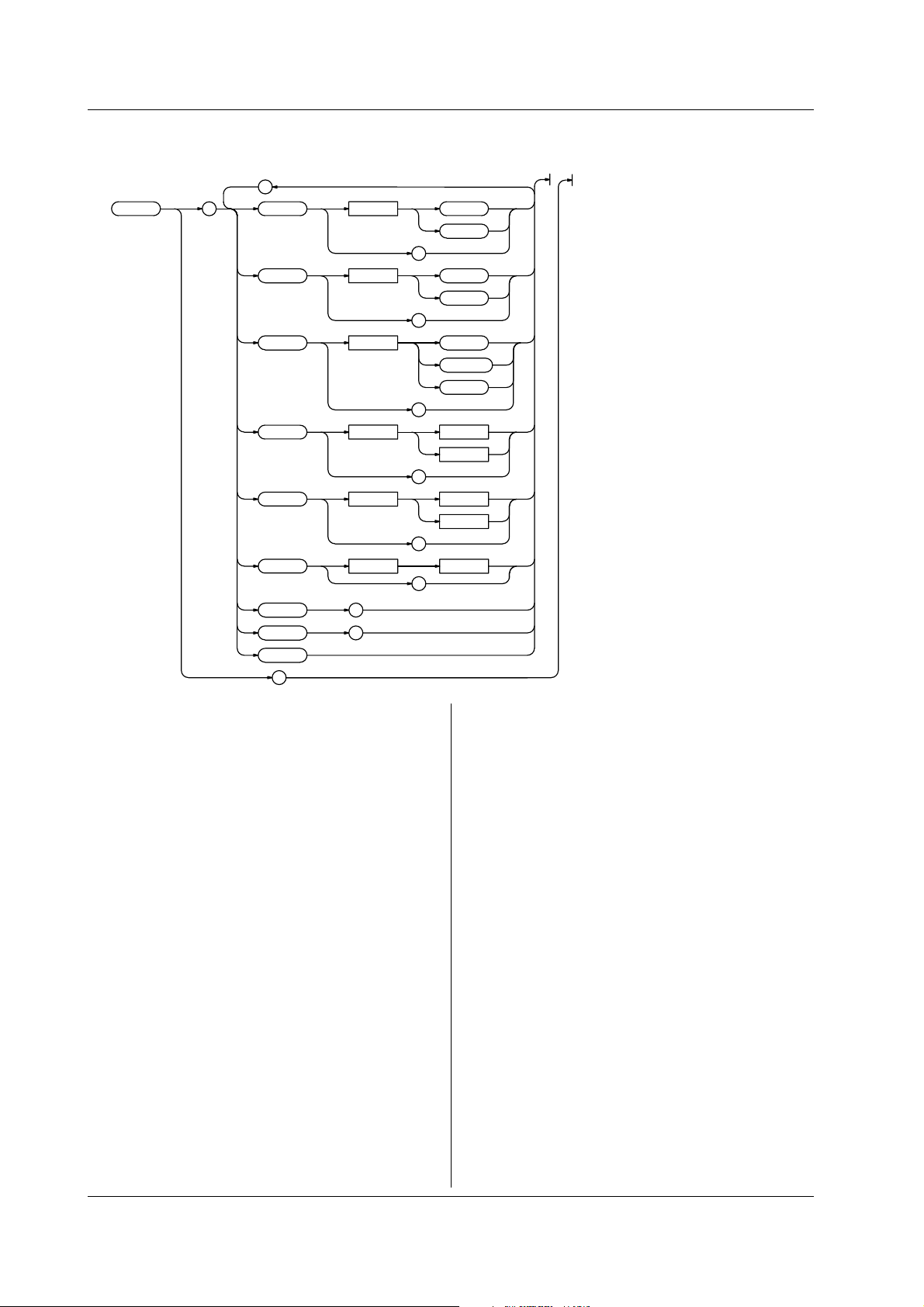
3.11 MEMory Group
3.11 MEMory Group
The commands in this group deal with the transmission of the measured data to external devices.
;
:MEMor y : FORMat <Space> ASCii
BINar y
?
BYTeorder <Space> LSBFirst
MSBFirst
?
DATaselect <Space> FREQuency
MEASuredata
TSTamp
?
STARt <Space>
END <Space>
BLOCk
<Space>
<Time>
<NRf>
?
<Time>
<NRf>
?
<NRf>
?
SIZE
SEND
CLEar
?
MEMory?
Function Queries all settings related to the transmission
of the measured data to external devices.
Syntax :MEMory?
?
?
MEMory:CLEar
Function Clears the measured data.
Syntax :MEMory:CLEar
Example MEMORY:CLEAR
Example :MEMORY?
→:MEMORY:DATASELECT FREQUENCY;
FORMAT ASCII;BYTEORDER LSBFIRST;
START 0.000E-09;END 1.000E-09;BLOCK 1
MEMory:DATaselect
Function Sets the data to transmit or queries the current
setting.
Syntax :MEMory:DATaselect {TSTamp|MEASuredata|
MEMory:BLOCk
Function Sets the block during block sampling or queries
the current setting.
Syntax :MEMory:BLOCk <NRf>
:MEMory:BLOCk?
Example :MEMORY:BLOCK 1
:MEMORY:BLOCK?
→:MEMORY:BLOCK 1
Example :MEMORY:DATASELECT TSTAMP
Description If time stamp (TSTamp) is specified when the
FREQuency}
:MEMory:DATaselect?
:MEMORY:DATASELECT?
→:MEMORY:DATASELECT TSTAMP
measurement mode is set to histogram or
frequency (FREQuency) is specified when the
mode is set to time stamp, an error occurs
MEMory:BYTeorder
when executing the MEMory:SEND?command.
Function Sets the transmission byte order of the binary
data or queries the current setting.
Syntax :MEMory:BYTeorder {LSBFirst|MSBFirst}
:MEMory:BYTeorder?
Example :MEMORY:BYTEORDER LSBFIRST
:MEMORY:BYTEORDER?
→:MEMORY:BYTEORDER LSBFIRST
3-40 IM 704310-12E
Page 61

3.11 MEMory Group/3.12 RECall Group
MEMory:END
Function Sets the data to transmit or queries the current
setting.
Syntax :MEMory:END <NRf>
:MEMory:END?
During time stamp mode, <NRf>=Number of
points(1 to 512,000)
During hardware histogram mode,
<Time>= -3.5 ns to 3.2 ms (in 25 ps
steps)
Example :MEMORY:END 1ns
:MEMORY:END?
→:MEMORY:END 1.000E-09
MEMory:FORMat
Function Sets the format of the transmission data or
queries the current setting.
Syntax :MEMory:FORMat {ASCii|BINary}
:MEMory:FORMat?
Example :MEMORY:FORMAT ASCII
:MEMORY:FORMAT?
→:MEMORY:FORMAT ASCII
MEMory:SEND?
Function Queries (transmits) the measured data
specified with the "MEMory:DATaselect"
command.
Syntax :MEMory:SEND?
Example :MEMORY:SEND?
→#800000016abcdabceabcfabcg
Description • When the transmission format is ASCII, the
response data in <NR3> format are output
the number of times equal to the number of
data points separated by commas (,). When
the format is BINARY, a single block of data
is output.
• The conversion equation from the binary data
to the real number is as follows:
For hardware histogram mode
Frequency (FREQuency):
Stored as an unsigned four-byte integer
Measured data (MEASuredata):
Consider it an unsigned four-byte integer.
The measured value is this number multiplied
by 25 ps.
For time stamp mode
Frequency (FREQuency):
Frequency cannot be output directly in the
time stamp mode.
Measured data (MEASuredata):
Consider it an unsigned four-byte integer.
The measured value is this number multiplied
by 25 ps.
Time stamp value (TSTamp):
Consider it an unsigned four-byte integer.
The time stamp value is this number
multiplied the following times.
When the sampling interval is 0 (MINimum)
:100 ns
When the sampling interval is 1 µs or longer
:1 µs
MEMory:SIZE?
Function Queries the number of measured data points.
Syntax :MEMory:SIZE?
Example :MEMORY:SIZE?
→10000
Description [NAN] is returned when the sampling mode is set
to hardware histogram.
MEMory:STARt
Function Sets the data position of the start of the
transmission or queries the current setting.
Syntax :MEMory:STARt <NRf>
:MEMory:STARt?
During time stamp mode, <NRf>=Number of
points(1 to 512,000)
During hardware histogram mode,
<Time>= -3.5 ns to 3.2 µs (in 25 ps
steps)
Example :MEMORY:START 1ns
:MEMORY:START?
→:MEMORY:START 1.000E-09
3
Commands
3.12 RECall Group
:RECall <Space> <NRf>
RECall
Function Recalls the setup information.
Syntax RECall <NRf>
<NRf>=0 to 9
Example RECALL 0
3-41IM 704310-12E
Page 62

3.13 SAMPle Group
3.13 SAMPle Group
The commands in this group deal with the sampling condition settings.
;
;
:SAMPle : ARMing : SOURce <Space> AUTO
EXTernal
?
SLOPe <Space> RISE
FALL
?
;
DELay : MODE <Space> TIME
TIME <Space>
EVENtsiz e <Space> <NRf>
;
EVENt
OFF
?
<Time>
?
?
?
?
BLOCk : STAT e <Space> OFF
ON
<NRf>
?
SIZE <Space> <NRf>
?
;
REST : MODE <Space> OFF
EVENt <Space> <NRf>
TIME <Space>
EVENt
TIME
?
?
<Time>
?
?
?
3-42 IM 704310-12E
Page 63

;
GATE : MODE <Space> EVENt
EXTernal
?
EVENtsiz e <Space> <NRf>
?
TIME <Space>
POLarity <Space> POSitive
INHibit <Space> OFF
POSitive
NEGative
?
INTer val <Space>
RCLock <Space> INTernal
<Time>
MINimum
?
EXTernal
?
?
<Time>
?
NEGative
?
?
3.13 SAMPle Group
TIME
3
Commands
SAMPle?
Function Queries all settings related to sampling.
Syntax :SAMPle?
Example :SAMPLE?
→:SAMPLE:ARMING:MODE OFF;:SAMPLE:BLOCK:
STATE 0;:SAMPLE:GATE:MODE EVENT;
EVENTSIZE 1000;:SAMPLE:INHIBIT OFF:
RCLOCK INTERNAL
SAMPle:ARMing?
Function Queries all settings related to the arming
function.
Syntax :SAMPle:ARMing?
Example :SAMPLE:ARMING?
→:SAMPLE:ARMING:SOURCE EXTERNAL;
SLOPE RISE;DELAY:MODE EVENT;
EVENTSIZE 1000
SAMPle:ARMing:DELay?
Function Queries all settings related to the arming delay.
Syntax :SAMPle:ARMing:DELay?
Example :SAMPLE:ARMING:DELAY?
→:SAMPLE:ARMING:DELAY:MODE EVENT;
EVENTSIZE 1000
SAMPle:ARMing:DELay:EVENtsize
Function Sets the arming delay event or queries the
current setting.
Syntax :SAMPLe:ARMing:DELay:EVENtsize <NRf>
:SAMPle:ARMing:DELay:EVENtsize?
<NRf>=Number of events (1 to 1000000)
Example :SAMPLE:ARMING:DELAY:EVENTSIZE 1000
:SAMPLE:ARMING:DELAY:EVENTSIZE?
→:SAMPLE:ARMING:DELAY:EVENTSIZE 1000
SAMPle:ARMing:DELay:MODE
Function Sets the arming delay mode or queries the
current setting.
Syntax :SAMPLe:ARMing:DELay[:MODE] {TIME|EVENt|
OFF}
:SAMPle:ARMing:DELay:MODE?
Example :SAMPLE:ARMING:DELAY:MODE OFF
:SAMPLE:ARMING:DELAY:MODE?
→:SAMPLE:ARMING:DELAY:MODE OFF
3-43IM 704310-12E
Page 64

3.13 SAMPle Group
SAMPle:ARMing:DELay:TIME
Function Sets the arming delay time or queries the
current setting.
Syntax :SAMPLe:ARMing:DELay:TIME <Time>
:SAMPle:ARMing:DELay:TIME?
<Time>=1 µs to 1s(in 100 ns steps)
Example :SAMPLE:ARMING:DELAY:TIME 1us
:SAMPLE:ARMING:DELAY:TIME?
→:SAMPLE:ARMING:DELAY:TIME 1.0E-06
SAMPle:ARMing:SLOPe
Function Sets the arming slope or queries the current
setting.
Syntax :SAMPLe:ARMing:SLOPe {RISE|FALL}
:SAMPle:ARMing:SLOPe?
Example :SAMPLE:ARMING:SLOPE RISE
:SAMPLE:ARMING:SLOPE?
→:SAMPLE:ARMING:SLOPE RISE
SAMPle:ARMing:SOURce
Function Sets the arming source or queries the current
setting.
Syntax :SAMPLe:ARMing:SOURce {AUTO|EXTernal}
:SAMPle:ARMing:SOURce?
Example :SAMPLE:ARMING:SOURCE AUTO
:SAMPLE:ARMING:SOURCE?
→:SAMPLE:ARMING:SOURCE AUTO
SAMPle:BLOCk?
Function Queries all settings related to block sampling.
Syntax :SAMPle:BLOCk?
Example :SAMPLE:BLOCK?
→:SAMPLE:BLOCK:STATE 1;SIZE 10;REST:
MODE EVENT;EVENT 1000
SAMPle:BLOCk:REST?
Function Queries all settings related to the pause period
of the block sampling operation.
Syntax :SAMPle:BLOCk:REST?
Example :SAMPLE:BLOCK:REST?
→:SAMPLE:BLOCK:REST:MODE EVENT;
EVENT 1000
SAMPle:BLOCk:REST:EVENt
Function Sets the pause time of the block sampling
operation in terms of the number of events or
queries the current setting.
Syntax :SAMPLe:BLOCk:REST:EVENt <NRf>
:SAMPle:BLOCk:REST:EVENt?
<NRf>=Number of events (1 to 1000000)
Example :SAMPLE:BLOCK:REST:EVENT 1000
:SAMPLE:BLOCK:REST:EVENT?
→:SAMPLE:BLOCK:REST:EVENT 1000
SAMPle:BLOCk:REST[:MODE]
Function Sets the pause mode of the block sampling
operation or queries the current setting.
Syntax :SAMPLe:BLOCk:REST[:MODE] {OFF|EVENt|
TIME}
:SAMPle:BLOCk:REST:MODE?
Example :SAMPLE:BLOCK:REST:MODE OFF
:SAMPLE:BLOCK:REST:MODE?
→:SAMPLE:BLOCK:REST:MODE OFF
SAMPle:BLOCk:REST:TIME
Function Sets the pause time of the block sampling
operation or queries the current setting.
Syntax :SAMPLe:BLOCk:REST:TIME <Time>
:SAMPle:BLOCk:REST:TIME?
<Time>=1 µs to 1 s (in 100 ns steps)
Example :SAMPLE:BLOCK:REST:TIME 1us
:SAMPLE:BLOCK:REST:TIME?
→:SAMPLE:BLOCK:REST:TIME 1.0E-6
SAMPle:BLOCk:SIZE
Function Sets the block size of the block sampling
operation or queries the current setting.
Syntax :SAMPLe:BLOCk:SIZE <NRf>
:SAMPle:BLOCk:SIZE?
<NRf> =1 to 100 (during time stamp mode)
=1 to 1000 (during hardware
histogram mode)
Example :SAMPLE:BLOCK:SIZE 10
:SAMPLE:BLOCK:SIZE?
→:SAMPLE:BLOCK:SIZE 10
SAMPle:BLOCk[:STATe]
Function Turns ON/OFF the block sampling function or
queries the current setting.
Syntax :SAMPLe:BLOCk[:STATe] <Boolean>
:SAMPle:BLOCk:STATe?
Example :SAMPLE:BLOCK:STATE ON
:SAMPLE:BLOCK:STATE?
→:SAMPLE:BLOCK:STATE 1
SAMPle:GATE?
Function Queries all settings related to the gate.
Syntax :SAMPle:GATE?
Example :SAMPLE:GATE?
→:SAMPLE:GATE:MODE EVENT;EVENTSIZE 1000
3-44 IM 704310-12E
Page 65

3.13 SAMPle Group
SAMPle:GATE:EVENtsize
Function Sets the gate in terms of the number of events
or queries the current setting.
Syntax :SAMPLe:GATE:EVENtsize <NRf>
:SAMPle:GATE:EVENtsize?
<NRf> =1 to 512,000 (during time stamp
mode)
=1 to 1,000,000,000 (during
hardware histogram mode)
Example :SAMPLE:GATE:EVENTSIZE 1000
:SAMPLE:GATE:EVENTSIZE?
→:SAMPLE:GATE:EVENTSIZE 1000
SAMPle:GATE[:MODE]
Function Sets the gate type or queries the current
setting.
Syntax :SAMPLe:GATE[:MODE] {EVENt|TIME|
EXTernal}
:SAMPle:GATE:MODE?
Example :SAMPLE:GATE:MODE EVENT
:SAMPLE:GATE:MODE?
→:SAMPLE:GATE:MODE EVENT
SAMPle:GATE:POLarity
Function Sets the polarity of the external gate or queries
the current setting.
Syntax :SAMPLe:GATE:POLarity {POSitive|
NEGative}
:SAMPle:GATE:POLarity?
Example :SAMPLE:GATE:POLARITY POSITIVE
:SAMPLE:GATE:POLARITY?
→:SAMPLE:GATE:POLARITY POSITIVE
SAMPle:INTerval
Function Sets the sampling interval or queries the current
setting.
Syntax :SAMPLe:INTerval {<Time>|MINimum}
:SAMPle:INTerval?
<Time>=0 to 1 s (in 1 µs steps)
Example :SAMPLE:INTERVAL MINIMUM
:SAMPLE:INTERVAL?
→:SAMPLE:INTERVAL 0.0E-06
Description The sampling interval is set to the minimum
value when "MINimum" is sent in the data or 0 is
specified for <Time>. In this case, 0 s is
returned as a response to the query.
SAMPle:RCLock
Function Sets the reference clock for sampling or queries
the current setting.
Syntax :SAMPLe:RCLock {INTernal|EXTernal}
:SAMPle:RCLock?
Example :SAMPLE:RCLOCK INTERNAL
:SAMPLE:RCLOCK?
→:SAMPLE:RCLOCK INTERNAL
3
Commands
SAMPle:GATE:TIME
Function Sets the gate in terms of time or queries the
current setting.
Syntax :SAMPLe:GATE:TIME <Time>
:SAMPle:GATE:TIME?
<Time>=1 µs to 10 s (in 100 ns steps)
Example :SAMPLE:GATE:TIME 1us
:SAMPLE:GATE:TIME?
→:SAMPLE:GATE:TIME 1.0E-06
SAMPle:INHibit
Function Sets the polarity of the inhibit input or queries
the current setting.
Syntax :SAMPLe:INHibit {OFF|POSitive|NEGative}
:SAMPle:INHibit?
Example :SAMPLE:INHIBIT OFF
:SAMPLE:INHIBIT?
→:SAMPLE:INHIBIT OFF
Description The inhibit input is disabled if it is turned "OFF."
3-45IM 704310-12E
Page 66

3.14 SCSI Group/3.15 SSTart Group/3.16 STARt Group
3.14 SCSI Group
The commands in this group deal with the SCSI settings.
;
:SCSI : INITializ e
OWN <Space> <NRf>
?
HDD <Space> <NRf>
?
?
SCSI?
Function Queries all settings related to SCSI.
Syntax :SCSI?
Example :SCSI?
→:SCSI:OWN 0;HDD 1
SCSI:HDD
Function Sets the SCSI address of the internal hard disk
or queries the current setting.
Syntax :SCSI:HDD <NRf>
:SCSI:HDD?
<NRf>=0 to 7
Example :SCSI:HDD 1
:SCSI:HDD?
→:SCSI:HDD 1
3.15 SSTart Group
:SSTar t
SSTart
Function Executes single measurement.
Syntax :SSTart
Example :SSTART
SCSI:INITialize
Function Initializes the SCSI.
Syntax :SCSI:INITialize
Example :SCSI:INITIALIZE
SCSI:OWN
Function Sets the SCSI address of the instrument or
queries the current setting.
Syntax :SCSI:OWN <NRf>
:SCSI:OWN?
<NRf>=0 to 7
Example :SCSI:OWN 0
:SCSI:OWN?
→:SCSI:OWN 0
3.16 STARt Group
:STARt
STARt
Function Starts the measurement.
Syntax :STARt
Example :START
3-46 IM 704310-12E
Page 67

3.17 STATus Group
The commands in this group deal with the communication status. For status reports, see chapter 4.
;
:S TATus : CONDition ?
EESE <Space> <Register>
?
EESR ?
ERRor ?
FILTer <x> <Space> RISE
FALL
BOTH
NEVer
?
QMESsage <Space> OFF
ON
<NRf>
?
?
3.17 STATus Group
3
Commands
STATus?
Function Queries all settings related to the
communication status.
Syntax :STATus?
Example :STATUS?
→:STATUS:EESE 0;FILTER1 RISE;
FILTER2 NEVER;FILTER3 NEVER;
FILTER4 NEVER;FILTER5 NEVER;
FILTER6 NEVER;FILTER7 NEVER;
FILTER8 NEVER;FILTER9 RISE;
FILTER10 RISE;FILTER11 RISE;
FILTER12 RISE;FILTER13 RISE;
FILTER14 NEVER;FILTER15 NEVER;
FILTER16 NEVER;QMESSAGE 1
STATus:CONDition?
Function Queries the status register.
Syntax :STATus:CONDition?
Example :STATUS:CONDITON?→16
STATus:EESE
Function Sets the extended event enable register or
queries the current setting.
Syntax :STATus:EESE <Register>
:STATus:EESE?
<Register>=0 to 65535
Example :STATUS:EESE 257
:STATUS:EESE?→:STATUS:EESE 257
STATus:ERRor?
Function Queries the error code and message (top of the
error queue).
Syntax :STATus:ERRor?
Example :STATUS:ERROR?→113,"Undefine header"
STATus:FILTer<x>
Function Sets the transition filter or queries the current
setting.
Syntax :STATus:FILTer<x> {RISE|FALL|BOTH|
NEVer}
:STATus:FILTer<x>?
<x>=1 to 16
Example :STATUS:FILTER2 RISE
:STATUS:FILTER2?
→:STATUS:FILTER2 RISE
STATus:QMESsage
Function Sets whether or not to include the message
information in response to the
"STATus:ERRor?" command or queries the
current setting.
Syntax :STATus:QMESsage <Boolean>
:STATus:QMESsage?
Example :STATUS:QMESSAGE OFF
:STATUS:QMESSAGE?→:STATUS:QMESSAGE 0
STATus:EESR?
Function Queries the extended event register and clears
the register.
Syntax :STATus:EESR?
Example :STATUS:EESR?→1
3-47IM 704310-12E
Page 68

3.18 STOP Group/3.19 STORe Group/3.20 SYSTem Group
3.18 STOP Group
:STOP
STOP
Function Stops the measurement.
Syntax :STOP
Example :STOP
3.19 STORe Group
:STORe <Space> <NRf>
STORe
Function Stores the current setup information.
Syntax :STORe <NRf>
<NRf>=0 to 9
Example :STORE 0
3.20 SYSTem Group
The commands in this group deal with the system settings such as date and time.
;
:SYSTem : DATE <Space> <String>
<NRf> , <NRf> , <NRf>
?
TIME <Space> <String>
<NRf> , <NRf>
?
BEEP <Space> OFF
ON
<NRf>
?
CLICksound <Space> OFF
ON
<NRf>
?
HDDMotor
WARNing
<Space> OFF
ON
<NRf>
?
<Space> OFF
ON
<NRf>
?
?
SYSTem?
Function Queries all settings related to the SYSTem
group.
Syntax SYSTem?
Example :SYSTEM?
→:SYSTEM:BEEP 1:CLICKSOUND 1;HDDMOTOR 1
SYSTem:BEEP
Function Turns ON/OFF the beep sound or queries the
current setting.
Syntax :SYSTem:BEEP <Boolean>
Example :SYSTEM:BEEP ON
:SYSTEM:BEEP?
→:SYSTEM:BEEP 1
3-48 IM 704310-12E
Page 69

SYSTem:CLICksound
Function Turns ON/OFF the click sound or queries the
current setting.
Syntax :SYSTem:CLICksound <Boolean>
Example :SYSTEM:CLICKSOUND ON
:SYSTEM:CLICKSOUND?
→:SYSTEM:CLICKSOUND 1
3.20 SYSTem Group
SYSTem:DATE
Function Sets today's date or queries the current setting.
Syntax :SYSTem:DATE {<string>|,<NRf>,<NRf>,
<NRf>}
:SYSTem:DATE?
Example :SYSTEM:DATE "1999/01/01"
:SYSTEM:DATE?
→"1999/01/01"
Description The <String> must be in the form [Year(4
digits)/Month(2 digits)/Date(2 digits)] as shown
above. For <NRf> format, write year, month,
date in that order.
SYSTem:HDDMotor
Function Turns ON/OFF the HDD motor while waiting or
queries the current setting.
Syntax :SYSTem:HDDMotor <Boolean>
Example :SYSTEM:HDDMOTOR ON
:SYSTEM:HDDMOTOR?
→:SYSTEM:HDDMOTOR 1
SYSTem:TIME
Function Sets the current time or queries the current
setting.
Syntax :SYSTem:TIME {<string>|,<NRf>,<NRf>}
:SYSTem:TIME?
Example :SYSTEM:TIME "12:00"
:SYSTEM:TIME?
→"12:00:00"
Description The <String> must be in the form [Hour(2
digits)/Minute(2 digits)] as shown above. For
<NRf> format, write hour and minute in that
order. The response to the query will also
include a value for the number of seconds.
3
Commands
SYSTem:WARNing
Function Turn ON/OFF the warning display or queries
the current setting.
Syntax :SYSTem:WARNing <Boolean>
:SYSTem:WARNing?
Example :SYSTEM:WARNING ON
:SYSTEM:WARNING?
→:SYSTEM:WARNING 1
3-49IM 704310-12E
Page 70

3.21 THIStogram Group
3.21 THIStogram Group
The commands in this group deal with the histogram settings of the time stamp mode.
;
;
:THIStogram : MARKer : STAT e <Space> OFF
ON
<NRf>
?
LEFT <Space>
RIGHt <Space>
LV ALue ?
RVALue ?
LOW <Space> <NRf>
;
ISI : S TAT e <Space> OFF
MODE <Space> SINGle
POLarity <Space> SPACe
TRIGg er <Space> SPACe
SPACe <x> <Space> <NRf>
MARK <x> <Space> <NRf>
<Time>
?
<Time>
?
?
?
ON
<NRf>
?
COMBination
BETWeen
?
MARK
?
MARK
STOMark
MTOSpace
STOSpace
MTOMark
?
?
?
3-50 IM 704310-12E
Page 71

TARGet <Space> PREVious
BOTH
?
SIZE <Space> <NRf>
?
UPDate
TVALue <Space>
WINDow <x> : LABel <Space> <NRf>
;
VERTical : AXIS <Space> LINear
HIGH <Space> <NRf>
;
HORizontal : CENTer <Space>
SPAN <Space>
<Time>
?
LOGarithmic
?
?
?
<Time>
?
<Time>
?
?
?
NEXT
;
?
;
HORizontal : CENTer <Space>
SPAN <Space>
;
MARKer : LEFT <Space>
RIGHt <Space>
?
3.21 THIStogram Group
3
Commands
<Time>
?
<Time>
?
?
<Time>
?
<Time>
?
?
?
3-51IM 704310-12E
Page 72

3.21 THIStogram Group
THIStogram?
Function Queries all settings related to the histogram of
the time stamp mode.
Syntax :THIStogram?
Example :THISTOGRAM?
→:THISTOGRAM:MARKER:LEFT 100.000E-09;
RIGHT 200.000E-09;LOW 0.1E+03;:
THISTOGRAM:ISI:STATE 0;:THISTOGRAM:
VERTICAL:AXIS LINEAR;HIGH 1.0E+03;:
THISTOGRAM:HORIZONTAL:
CENTER 150.000E-09;SPAN 0.3E-06
THIStogram:HORizontal?
Function Queries all settings related to the horizontal
axis of the histogram of the time stamp mode.
Syntax :THIStogram:HORizontal?
Example :THISTOGRAM:HORIZONTAL?
→:THISTOGRAM:HORIZONTAL:
CENTER 150.000E-09;SPAN 0.3E-06
THIStogram:HORizontal:CENTer
Function Sets the center value of the horizontal axis or
queries the current setting.
Syntax :THIStogram:HORizontal:CENTer <Time>
:THIStogram:HORizontal:CENTer?
<Time>=-50 ns to +20 ms (in 25 ps steps)
Example :THISTOGRAM:HORIZONTAL:CENTER 150ns
:THISTOGRAM:HORIZONTAL:CENTER?
→:THISTOGRAM:HORIZONTAL:
CENTER 150.000E-09
THIStogram:HORizontal:SPAN
Function Sets the width of the horizontal axis or queries
the current setting.
Syntax :THIStogram:HORizontal:SPAN <Time>
:THIStogram:HORizontal:SPAN?
<Time>= 1.5 ns,3 ns,7.5 ns,15 ns,30 ns,60
ns,…..,6 ms,15 ms,30 ms
Example :THISTOGRAM:HORIZONTAL:SPAN 300ns
:THISTOGRAM:HORIZONTAL:SPAN?
→:THISTOGRAM:HORIZONTAL:SPAN 0.3E-06
THIStogram:ISI?
Function Queries all settings related to the inter-symbol
interference analysis.
Syntax :THIStogram:ISI?
Example :THISTOGRAM:ISI?
→:THISTOGRAM:ISI:STATE 1;MODE SINGLE;
POLARITY MARK;TRIGGER MARK;MARK1 3;
TARGET PREVIOUS;SIZE 1;
TVALUE 40.000E-09;WINDOW1:
LABEL 3;HORIZONTAL:CENTER 150.000E-09;
SPAN 0.3E-06;:THISTOGRAM:ISI:WINDOW1:
MARKER:LEFT 100.000E-09;
RIGHTT 200.000E-09
THIStogram:ISI:MARK<x>
Function Sets the mark or queries the current setting.
Syntax :THIStogram:ISI:MARK<x> <NRf>
:THIStogram:ISI:MARK<x>?
<NRf>=Window label
Example :THIStogram:ISI:MARK<x> 3
:THIStogram:ISI:MARK<x>?
→:THISTOGRAM:ISI:MARK<x> 3
Description When the trigger condition is MARK or
MTOSpace, MARK1 can be specified. For
STOMark, only MARK2 can be specified. For
MTOMark, both MARK1 and MARK2 can be
specified. For all other cases, MARK<x>
cannot be specified.
THIStogram:ISI:MODE
Function Sets the trigger mode or queries the current
setting.
Syntax :THIStogram:ISI:MODE {SINGle|
COMBination|BETWeen}
:THIStogram:ISI:MODE?
Example :THISTOGRAM:ISI:MODE SINGLE
:THISTOGRAM:ISI:MODE?
→:THISTOGRAM:ISI:MODE SINGLE
THIStogram:ISI:POLarity
Function Sets the polarity or queries the current setting.
Syntax :THIStogram:ISI:POLarity {MARK|SPACe}
:THIStogram:ISI:POLarity?
Example :THISTOGRAM:ISI:POLARITY MARK
:THISTOGRAM:ISI:POLARITY?
→:THISTOGRAM:ISI:POLARITY MARK
THIStogram:ISI:SIZE
Function Sets the number of windows or queries the
current setting.
Syntax :THIStogram:ISI:SIZE <NRf>
:THIStogram:ISI:SIZE?
<NRf>=1 to 16
Example :THISTOGRAM:ISI:SIZE 10
:THISTOGRAM:ISI:SIZE?
→:THISTOGRAM:ISI:SIZE 10
3-52 IM 704310-12E
Page 73

3.21 THIStogram Group
THIStogram:ISI:SPACe<x>
Function Sets the space or queries the current setting.
Syntax :THIStogram:ISI:SPACe<x> <NRf>
:THIStogram:ISI:SPACe<x>?
<NRf>=Window label
Example :THIStogram:ISI:SPACe<x> 3
:THIStogram:ISI:SPACe<x>?
→:THIStogram:ISI:SPACe<x> 3
Description When the trigger condition is SPACe or
STOMark, only SPACe1 can be specified. For
MTOSpace, only SPACe2 can be specified. For
STOSpace, both SPACe1 and SPACe2 can be
specified. For all other cases SPACe<x>
cannot be specified.
THIStogram:ISI[:STATe]
Function Turns ON/OFF the inter-symbol interference
analysis function or queries the current setting.
Syntax :THIStogram:ISI[:STATe] <Boolean>
:THIStogram:ISI:STATe?
Example :THISTOGRAM:ISI:STATE ON
:THISTOGRAM:ISI:STATE?
→:THISTOGRAM:ISI:STATE ON
THIStogram:ISI:TARGet
Function Sets the item to be analyzed or queries the
current setting.
Syntax :THIStogram:ISI:TARGet {PREVious|NEXT|
BOTH}
:THIStogram:ISI:TARGet?
Example :THISTOGRAM:ISI:TARGET PREVIOUS
:THISTOGRAM:ISI:TARGET?
→:THISTOGRAM:ISI:TARGET PREVIOUS
Description When the trigger mode is SINGle, PREVious,
NEXT, or BOTH can be specified. For
COMBination, only PREVious or NEXT can be
specified. For BETWEEN, nothing can be
specified.
THIStogram:ISI:TRIGger
Function Sets the trigger condition or queries the current
setting.
Syntax :THIStogram:ISI:TRIGger
{MARK|SPACe|MTOSpace|STOMark|MTOMark|
STOSpace}
:THIStogram:ISI:TRIGger?
Example :THISTOGRAM:ISI:TRIGGER MARK
:THISTOGRAM:ISI:TRIGGER?
→:THISTOGRAM:ISI:TRIGGER MARK
Description When the trigger mode is SINGle, MARK or
SPACE can be specified. For COMBination,
MTOSpace or STOMark can be specified. For
BETWEEN, MTOMark or STOSpace can be
specified.
THIStogram:ISI:TVALue
Function Sets the value of the constant T or queries the
current setting.
Syntax :THIStogram:ISI:TVALue <Time>
:THIStogram:ISI:TVALue?
<Time>=1 ns to 250 ns (in 25 ps steps)
Example :THISTOGRAM:ISI:TVALUE 100ns
:THISTOGRAM:ISI:TVALUE?
→:HHISTOGRAM:SINGLE:TVALUE 0.100000E-06
THIStogram:ISI:UPDate
Function Changes the window setting based on the
constant T.
Syntax :THIStogram:ISI:UPDate
Example :THISTOGRAM:ISI:UPDATE
THIStogram:ISI:WINDow<x>?
Function Queries all settings related to each window.
Syntax :THIStogram:ISI:WINDow<x>?
Example :THISTOGRAM:ISI:WINDOW1?
→:THISTOGRAM:ISI:WINDOW1:LABEL 3;
HORIZONTAL:CENTER 150.000E-09;
SPAN 0.3E-06;:THISTOGRAM:ISI:WINDOW1:
MARKER:LEFT 100.000E-09;
RIGHTT 200.000E-09
THIStogram:ISI:WINDow<x>:HORizontal?
Function Queries all settings related to the horizontal
axis of each window.
Syntax :THIStogram:ISI:WINDow<x>:HORizontal?
Example :THISTOGRAM:ISI:WINDOW1:HORIZONTAL:
CENTER?
→:THISTOGRAM:ISI:WINDOW1:HORIZONTAL:
CENTER 150.000E-09;SPAN 0.3E-06
THIStogram:ISI:WINDow<x>:HORizontal:CENTer
Function Sets the center value of the horizontal axis or
queries the current setting.
Syntax :THIStogram:ISI:WINDow<x>:HORizontal:
CENTer <Time>
:THIStogram:ISI:WINDow<x>:HORizontal:
CENTer?
<Time>=-50 ns to 3.2 µs (in 25 ps steps)
Example :THISTOGRAM:ISI:WINDOW1:HORIZONTAL:
CENTER 150ns
:THISTOGRAM:ISI:WINDOW1:HORIZONTAL:
CENTER?
→:THISTOGRAM:ISI:WINDOW1:HORIZONTAL:
CENTER 150.000E-09
3
Commands
3-53IM 704310-12E
Page 74

3.21 THIStogram Group
THIStogram:ISI:WINDow<x>:HORizontal:SPAN
Function Sets the width of the horizontal axis or queries
the current setting.
Syntax :THIStogram:ISI:WINDow<x>:HORizontal:
SPAN <Time>
:THIStogram:ISI:WINDow<x>:HORizontal:
SPAN?
<Time>= 1.5 ns,3 ns,7.5 ns,15 ns,30 ns,60
ns,150 ns,300 ns,600 ns,1.5 µs,3
µs,6 µs
Example :THISTOGRAM:ISI:WINDOW1:HORIZONTAL:
SPAN 300ns
:THISTOGRAM:ISI:WINDOW1:HORIZONTAL:SPAN?
→:THISTOGRAM:ISI:WINDOW1:HORIZONTAL:
SPAN 0.3E-06
THIStogram:ISI:WINDow<x>:LABel
Function Sets the label of each window or queries the
current setting.
Syntax :THIStogram:ISI:WINDow<x>:LABel <NRf>
:THIStogram:ISI:WINDow<x>:LABel?
<NRf>=1 to 32
Example :THISTOGRAM:ISI:WINDOW1:LABEL 3
:THISTOGRAM:ISI:WINDOW1:LABEL?
→:THISTOGRAM:ISI:WINDOW1:LABEL 3
THIStogram:ISI:WINDow<x>:MARKer?
Function Queries all settings related to the horizontal
marker cursor of each window.
Syntax :THIStogram:ISI:WINDow<x>:HORizontal?
Example :THISTOGRAM:ISI:WINDOW1:MARKER?
→:THISTOGRAM:ISI:WINDOW1:MARKER:
LEFT 100.000E-09;RIGHTT 200.000E-09
THIStogram:ISI:WINDow<x>:MARKer:LEFT
Function Sets the position of the left marker or queries
the current setting.
Syntax :THIStogram:ISI:WINDow<x>:MARKer:
LEFT <Time>
:THIStogram:ISI:WINDow<x>:MARKer:LEFT?
<Time>=marker position (in 25 ps steps)
Example :THISTOGRAM:ISI:WINDOW1:MARKER:
LEFT 100ns
:THISTOGRAM:ISI:WINDOW1:MARKER:LEFT?
→:THISTOGRAM:ISI:WINDOW1:MARKER:
LEFT 100.000E-09
THIStogram:ISI:WINDow<x>:MARKer:RIGHt
Function Sets the position of the right marker or queries
the current setting.
Syntax :THIStogram:ISI:WINDow<x>:MARKer:
RIGHt <Time>
:THIStogram:ISI:WINDow<x>:MARKer:RIGHt?
<Time>=marker position (in 25 ps steps)
Example :THISTOGRAM:ISI:WINDOW1:MARKER:
RIGHTT 200ns
:THISTOGRAM:ISI:WINDOW1:MARKER:RIGHT?
→:THISTOGRAM:ISI:WINDOW1:MARKER:
RIGHTT 200.000E-09
THIStogram:MARKer?
Function Queries all settings related to the markers.
Syntax :THIStogram:MARKer?
Example :THISTOGRAM:MARKER?
→:THISTOGRAM:MARKER:LEFT 100.000E-09;
RIGHT 200.000E-09;LOW 0.1E+03
THIStogram:MARKer:LEFT
Function Queries all settings related to the marker.
Syntax :THIStogram:MARKer:LEFT <Time>
:THIStogram:MARKer:LEFT?
<Time>=marker position (in 25 ps steps)
Example :THISTOGRAM:MARKER:LEFT?
→:THISTOGRAM:MARKER:LEFT 100.000E-09
THIStogram:MARKer:LOW
Function Sets the position of the low marker or queries
the current setting.
Syntax :THIStogram:MARKer:LOW <NRf>
:THIStogram:MARKer:LOW?
<NRf>=Frequency
Example :THISTOGRAM:MARKER:LOW 100
:THISTOGRAM:MARKER:LOW?
→:THISTOGRAM:MARKER:LOW 0.1E+03
THIStogram:MARKer:LVALue?
Function Queries the frequency at the left marker
position.
Syntax :THIStogram:MARKer:LVALue?
Example :THISTOGRAM:MARKER:LVALUE?
→0.123E+03
Description Cannot be used during inter-symbol
interference analysis (Use :THIStogram:ISI:
WINDow<x>:MARKer:LVALue?
).
3-54 IM 704310-12E
Page 75

THIStogram:MARKer:RIGHt
Function Sets the position of the right marker or queries
the current setting.
Syntax :THIStogram:MARKer:RIGHt <Time>
:THIStogram:MARKer:RIGHt?
<Time>=marker position (in 25 ps steps)
Example :THISTOGRAM:MARKER:RIGHT?
→:THISTOGRAM:MARKER:RIGHT 200.000E-09
THIStogram:MARKer:RVALue?
Function Queries the frequency at the right marker
position.
Syntax :THIStogram:MARKer:RVALue?
Example :THISTOGRAM:MARKER:RVALUE?
→0.123E+03
Description Cannot be used during inter-symbol
interference analysis (Use :THIStogram:ISI:
WINDow<x>:MARKer:RVALue?
).
THIStogram:MARKer[:STATe]
Function Turns ON/OFF the marker or queries the
current setting.
Syntax :THIStogram:MARKer[:STATe] <Boolean>
:THIStogram:MARKer:STATe?
3.21 THIStogram Group
3
Commands
THIStogram:VERTical?
Function Queries all settings related to the vertical axis.
Syntax :THIStogram:VERTical?
Example :THISTOGRAM:VERTICAL?
→:THISTOGRAM:VERTICAL:AXIS LINEAR;
HIGH 1.0E+03
THIStogram:VERTical:AXIS
Function Sets the type of vertical axis scale or queries the
current setting.
Syntax :THIStogram:VERTical:AXIS {LINear|
LOGarithmic}
:THIStogram:VERTical:AXIS?
Example :THISTOGRAM:VERTICAL:AXIS LINEAR
:THISTOGRAM:VERTICAL:AXIS?
→:THISTOGRAM:VERTICAL:AXIS LINEAR
THIStogram:VERTical:HIGH
Function Sets the upper limit of the vertical axis scale or
queries the current setting.
Syntax :THIStogram:VERTical:HIGH <NRf>
:THIStogram:VERTical:HIGH?
<NRf>=Upper frequency limit
For linear scale
10,20,40,100,200,400,1000,…..,1000000,
1E+7,1E+8,1E+9
For logarithmic scale
1E+1,1E+2,…..,1E+9
Example :THISTOGRAM:VERTICAL:HIGH 1000
:THISTOGRAM:VERTICAL:HIGH?
→:THISTOGRAM:VERTICAL:HIGH 1.0E+03
3-55IM 704310-12E
Page 76

3.22 TVARiation Group
3.22 TVARiation Group
The commands in this group deal with the time variation display.
;
;
:TVARiation : VERTical : CENTer <Space>
SPAN <Space>
;
HORizontal : MINimum <Space>
SPAN <Space>
;
MARKer : STAT e <Space> OFF
LEFT <Space>
RIGHt <Space>
LV ALue ?
RVALue ?
HIGH <Space>
LOW <Space>
<Time>
?
<Time>
?
?
<Time>
?
<Time>
?
?
ON
<NRf>
?
<Time>
?
<Time>
?
<Time>
?
<Time>
?
?
?
TVARiation?
Function Queries all settings related to the time variation
display.
Syntax :TVARiation?
Example :TVARIATION?
→:TVARIATION:VERTICAL:
CENTER 100.000E-09;SPAN 0.2E-06;:
TVARiation:HORizontal?
Function Queries all settings related to the horizontal
axis of the time variation display.
Syntax :TVARiation:HORizontal?
Example :TVARIATION:HORIZONTAL?
→:TVARIATION:HORIZONTAL:MINIMUM 0;
SPAN 0.3E-03
TVARIATION:HORIZONTAL:MINIMUM 0;
SPAN 0.3E-03;:TVARIATION:MARKER:STATE 1;
LEFT 1.0E-06;RIGHT 2.0E-06;
HIGH 100.000E-09;LOW 50.000E-09
3-56 IM 704310-12E
Page 77

3.22 TVARiation Group
TVARiation:HORizontal:MINimum
Function Sets the left end of the horizontal axis scale or
queries the current setting.
Syntax :TVARiation:HORizontal:MINimum <Time>
:TVARiation:HORizontal:MINimum?
<Time>=0 to 3200 s (in 100 ns steps)
Example :TVARIATION:HORIZONTAL:MINIMUM 0s
:TVARIATION:HORIZONTAL:MINIMUM?
→:TVARIATION:HORIZONTAL:MINIMUM 0.0E-06
TVARiation:HORizontal:SPAN
Function Sets the width of the horizontal axis scale or
queries the current setting.
Syntax :TVARiation:HORizontal:SPAN <Time>
:TVARiation:HORizontal:SPAN?
<Time>= 6 µs,12 µs,30 µs,600 µs,......,
600 s,1200 s,3000 s,6000s
Example :TVARIATION:HORIZONTAL:SPAN 300us
:TVARIATION:HORIZONTAL:SPAN?
→:TVARIATION:HORIZONTAL:SPAN 0.3E-03
TVARiation:MARKer?
Function Queries all settings related to the markers.
Syntax :TVARiation:MARKer?
Example :TVARIATION:MARKER?
→:TVARIATION:MARKER:STATE 1;
LEFT 1.0E-06;RIGHT 2.0E-06;
HIGH 100.000E-09;LOW 50.000E-09
TVARiation:MARKer:HIGH
Function Sets the position of the high marker or queries
the current setting.
Syntax :TVARiation:MARKer:HIGH <Time>
:TVARiation:MARKer:HIGH?
<Time>=marker position (in 25 ps steps)
Example :TVARIATION:MARKER:HIGH 100ns
:TVARIATION:MARKER:HIGH?
→:TVARIATION:MARKER:HIGH 100.000E-09
TVARiation:MARKer:LEFT
Function Sets the position of the left marker or queries
the current setting.
Syntax :TVARiation:MARKer:LEFT <Time>
:TVARiation:MARKer:LEFT?
<Time>=0 to 9200 s (in 100 ns steps)
Example :TVARIATION:MARKER:LEFT 150us
:TVARIATION:MARKER:LEFT?
→:TVARIATION:MARKER:LEFT 150.0E-03
TVARiation:MARKer:LOW
Function Sets the position of the low marker or queries
the current setting.
Syntax :TVARiation:MARKer:LOW <Time>
:TVARiation:MARKer:LOW?
<Time>=marker position (in 25 ps steps)
Example :TVARIATION:MARKER:LOW 100ns
:TVARIATION:MARKER:LOW?
→:TVARIATION:MARKER:LOW 100.000E-09
TVARiation:MARKer:LVALue?
Function Queries the measured value at the left marker
position.
Syntax :TVARiation:MARKer:LVALue?
Example :TVARIATION:MARKER:LVALUE?
→1.2000E-06
TVARiation:MARKer:RIGHt
Function Sets the position of the right marker or queries
the current setting.
Syntax :TVARiation:MARKer:RIGHt <Time>
:TVARiation:MARKer:RIGHt?
<Time>=0 to 9200 s (in 100 ns steps)
Example :TVARIATION:MARKER:RIGHT 150us
:TVARIATION:MARKER:RIGHT?
→:TVARIATION:MARKER:RIGHT 150.0E-03
TVARiation:MARKer:RVALue?
Function Queries the measured value of the right marker
position.
Syntax :TVARiation:MARKer:RVALue?
Example :TVARIATION:MARKER:RVALUE?
→1.2000E-06
TVARiation:MARKer[:STATe]
Function Turns ON/OFF the marker cursor or queries the
current setting.
Syntax :TVARiation:MARKer[:STATe] <Boolean>
:TVARiation:MARKer:STATe?
Example :TVARIATION:MARKER:STATE ON
:TVARIATION:MARKER:STATE?
→:TVARIATION:MARKER:STATE 1
TVARiation:VERTical?
Function Queries all settings related to the vertical axis.
Syntax :TVARiation:VERTical?
Example :TVARIATION:VERTICAL:CENTER?
→:TVARIATION:VERTICAL:
CENTER 100.000E-09;SPAN 0.2E-06
3
Commands
3-57IM 704310-12E
Page 78

3.22 TVARiation Group/3.23 UNIT Group
TVARiation:VERTical:CENTer
Function Sets the center value of the vertical axis or
queries the current setting.
Syntax :TVARiation:VERTical:CENTer <Time>
:TVARiation:VERTicalCENTer?
<Time>=50 ns to 20 ms (in 25 ps steps)
Example :TVARIATION:VERTICAL:CENTER 100ns
:TVARIATION:VERTICAL:CENTER?
→:TVARIATION:VERTICAL:
CENTER 100.000E-09
TVARiation:VERTical:SPAN
Function Sets the width of the vertical axis or queries the
current setting.
Syntax :TVARiation:VERTical:SPAN <Time>
:TVARiation:VERTical:SPAN?
<Time>= 500 ps,1 ns,2.5 ns,5 ns,10 ns,
Example :TVARIATION:VERTICAL:SPAN 200ns
:TVARIATION:VERTICAL:SPAN?
→:TVARIATION:VERTICAL:SPAN 0.2E-06
3.23 UNIT Group
The commands in this group deal with the default units of voltage, time, and frequency.
;
:UNIT
:
VOLTage <Space> < Multiplier > V
< Multiplier >
V
?
TIME <Space> < Multiplier >
< Multiplier >
S
?
20 ns,…..,2 ms,5 ms,10 ms,20 ms
S
UNIT?
Function Queries the default units for voltage, time, and
frequency.
Syntax :UNIT?
Example :UNIT?
→:UNIT:FREQUENCY HZ;VOLTAGE V;TIME S
UNIT:VOLTage
Function Sets the default unit for voltage or queries the
current setting.
Syntax :UNIT:VOLTage [<auxiliary unit>]V
:UNIT:VOLTage?
<multiplier> See section 2.4.
Example :UNIT:VOLTAGE V
:UNIT:VOLTAGE?
→:UNIT:VOLTAGE V
UNIT:TIME
Function Sets the default unit for time or queries the
current setting.
Syntax :UNIT:TIME [<auxiliary unit>]S
:UNIT:TIME?
<multiplier> See section 2.4.
Example :UNIT:TIME s
:UNIT:TIME?
→:UNIT:TIME S
?
3-58 IM 704310-12E
Page 79

3.24 Common Command Group
3.24 Common Command Group
The commands in the common command group are independent of the instrument’s functions, and are specified
in IEEE 488.2-1992.
;
*
*
*
*
*
*
*
*
*
*
*
*
*
CAL
CLS
ESE
ESR
IDN
OPC
OPC
RST
SRE
STB
TRG
TST
WAI
<Space> <NRf>
<Space> <NRf>
?
?
?
?
?
?
?
?
3
Commands
*CAL?
Function Performs calibration and queries the result.
Syntax *CAL?
Example *CAL?
Description [0] will be returned if calibration is completed
properly, and a value other than [0] will be
returned if an abnormality has been detected
during calibration.
*CLS
Function Clears the standard event register, extended
event register and error queue.
Syntax *CLS
Example *CLS
Description For details of the registers and queue, refer to
Chapter 4, "Status Report."
*ESE
Function Sets the value for the standard event enable
register/queries the current setting.
Syntax *ESE <NRf>
*ESE?
<NRf>=0 to 255
Example *ESE 253
*ESE?→253
Description For details of the standard event enable
register, refer to Chapter 4, "Status Report."
*ESR?
Function Queries the value of the standard event register
and clears it at the same time.
Syntax *ESR?
Example *ESR?→253
Description For details of the standard event enable
register, refer to Chapter 4, "Status Report."
*IDN?
Function Queries the instrument model.
Syntax *IDN?
Example *IDN?→YOKOGAWA,704210,0,1.01
Description A reply consists of manufacturer, model, serial
No. (not used, always fixed at [0]) and firmware
version.
*OPC
Function Sets bit 0 (OPC bit) of the standard event
register to [1] when execution of an overlap
command is completed. This command will be
ignored even if it is sent since overlap
commands are not supported by this
instrument.
Syntax *OPC
*OPC?
Function After "*OPC?" is sent, [1] will be returned if
execution of the designated overlap command
has been completed. [1] will also be returned
since overlap commands are not supported by
this instrument.
Syntax *OPC?
3-59IM 704310-12E
Page 80

3.24 Common Command Group
*RST
Function Initializes the set-up information.
Syntax *RST
Example *RST
Description The same function can be performed by
displaying initialize menu and pressing
[Execute] soft key. For details, refer to the
TA520 Time Interval Analyzer User's Manual.
*SRE
Function Sets the value of the service request enable
register/queries the current setting.
Syntax *SRE <NRf>
*SRE?
<NRf>=0 to 255
Example *SRE 239
*SRE?→239
*STB?
Function Queries the value of the status byte register.
Syntax *STB?
Example *STB?→4
Description For details of the status byte register, refer to
Chapter 4, "Status Report."
*TRG
Function The same function as when the SINGLE key is
pressed is performed.
Syntax *TRG
Description GET (Group Execute Trigger) multi-line
message has also the same effect as this
command.
*TST?
Function Executes a self-test and queries the test result.
Syntax *TST?
Example *TST?→0
Description • The same function can be performed by
selecting [Board] from the self-test menu.
•[0] will be returned if all the self test results
are satisfactory, and a value other than [0]
will be returned if an abnormality is detected
during the test.
*WAI
Function Waits for the command following "*WAI" until
execution of the designated overlap command
is completed. This command will be ignored
even if it is sent since overlap commands are
not supported by this instrument.
Syntax *WAI
3-60 IM 704310-12E
Page 81

4.1 Overview of the Status Report
Chapter 4 Status Report
4.1 Overview of the Status Report
Status Report
The figure below shows the status report which is read by a serial poll. This is an extended version of the one
specified in IEEE 488.2-1992.
OR
Occurrence
of a service
request
76543210
&
&
&
&
&
&
MSS
7 6 ESBMAVEES EAV 1 0
RQS
Service request enable register
&
Status byte
Output
queue
Error
queue
4
Status Report
76543210
&
&
&
OR
76543210
1514131211109876543210
&
&
&
&
&
&
&
OR
1514131211109876543210
1514131211109876543210
15 14131211109876543210
&
&
&
&
&
&
&
&
Standard event enable register
&
&
&
Standard event register
Extended event enable register
&
&
&
Extended event register
Transit filter
Condition filter
4-1IM 704310-12E
Page 82

4.1 Overview of the Status Report/4.2 Status Byte
Overview of Registers and Queues
Name Function Writing Reading
Status byte — Serial poll (RQS),
Service request Masks status byte. *SRE *SRE?
enable register
Standard event Change in device — *ESR?
register status
Standard event Masks standard *ESE *ESE?
enable register event register
Extended event Change in device — STATus:EESR?
register status
Extended event Masks standard STATus:EESE STATus:EESE?
enable register event register
Condition Current instrument status — STATus:CONDition?
register
Transit filter Extended event STATus:FILTer STATus:FILTer<x>
occurrence conditions <x>
Output queue Stores response message All executable queues
to a query.
Error queue Stores error Nos. — STATus:ERRor?
and messages.
*STB?(MSS)
Registers and Queues which Affect the Status Byte
Registers which affect each bit of the status byte are
shown below.
Standard event register : Sets bit 5 (ESB) of status byte to [1] or [0].
Output queue : Sets bit 4 (MAV) of status byte to [1] or [0].
Extended event register : Sets bit 3 (EES) of status byte to [1] or [0].
Error queue : Sets bit 2 (EAV) of status byte to [1] or [0].
Enable Registers
Registers which mask a bit so that the bit does not
affect the status byte, even if the bit is set to [1], are
shown below.
Status byte : Masks bits using the service request enable register.
Standard event register : Masks bits using the standard event enable register.
Extended event register : Masks bits using the extended event enable register.
Writing/Reading from Registers
The
*ESE command is used to set bits in the standard
event enable register to [ 1] or [0], and the
*ESR? query
is used to check whether bits in that register are set to
[1] or [ 0]. For details of these commands, refer to
Chapter 3.
4.2 Status Byte
Overview of Status Byte
RQS
7 6 ESBMAVEES EAV 1 0
MSS
Bits 0, 1 and 7
Not used (always
Bit 2 EAV (Error Available)
Set to [1] when the error queue is not empty, i.e. when
an error occurs. For details, refer to page 4-5.
Bit 3 EES (Extended Event Summary Bit)
Set to [1] when a logical AND of the extended event
register and the corresponding enable register is [1],
i.e. when an event takes place in the instrument. Refer
to page 4-4.
Bit 4 MAV (Message Available)
Set to "1" when the output queue is not empty, i.e.
when there is data which is to be output when an
inquiry is made. Refer to page 4-5.
Bit 5 ESB (Event Summary Bit)
Set to "1" when a logical AND of the standard event
register and the corresponding enable register is [1],
i.e. when an event takes place in the instrument. Refer
to page 4-3.
Bit 6 RQS (Request Status)/MSS (Master Summary
Status)
MSS is set to [1] when a logical AND of the status byte
(except for bit 6) and the service request enable
register is not [0], i.e. when the instrument is
requesting service from the controller.
RQS is set to [1] when MSS changes from [0] to [1],
and is cleared when a serial poll is performed or when
MSS changes to [0].
Bit Masking
To mask a bit in the status byte so that it does not
cause an SRQ, set the corresponding bit of the service
request enable register to
For example, to mask bit 2 (EAV) so that no service
will be requested, even if an error occurs, set bit 2 of
the service request enable register to [0]. This can be
done using the *SRE command. To query whether
each bit of the service request enable register is [1] or
[0], use *SRE?. For details of the *SRE command, refer
to Chapter 3.
"0")
"0".
4-2 IM 704310-12E
Page 83

4.2 Status Byte/4.3 Standard Event Register
Operation of the Status Byte
A service request is issued when bit 6 of the status
byte becomes [1]. Bit 6 becomes [1] when any of the
other bits becomes [1] (or when the corresponding bit
in the service request enable register becomes [1]).
For example, if an event takes place and the logical
OR of each bit of the standard event register and the
corresponding bit in the enable register is [1], bit 5
(ESB) will be set to "1". In this case, if bit 5 of the
service request enable register is [1], bit 6 (MSS) will
be set to [1], thus requesting service from the
controller.
It is also possible to check what type of event has
occurred by reading the contents of the status byte.
Reading from the Status Byte
The following two methods are provided for reading the
status byte.
• Inquiry using the *STB? query
Making an inquiry using the
*STB? query sets bit 6 to
MSS. This causes the MSS to be read. After
completion of the read-out, none of the bits in the
status byte will be cleared.
• Serial poll
Execution of a serial poll changes bit 6 to RQS. This
causes RQS to be read. After completion of the
read-out, only RQS is cleared. Using a serial poll, it
is not possible to read MSS.
Clearing the Status Byte
No method is provided for forcibly clearing all the bits
in the status byte. Bits which are cleared are shown
below.
• When an inquiry is made using the *STB? query
No bit is cleared.
• When a serial poll is performed
Only the RQS bit is cleared.
• When the *CLS command is received
When the
*CLS command is received, the status
byte itself is not cleared, but the contents of the
standard event register (which affects the bits in the
status byte) are cleared. As a result, the
corresponding bits in the status byte are cleared,
except bit 4 (MAV), since the output queue cannot
be emptied by the *CLS command. However, the
output queue will also be cleared if the
*CLS
command is received just after a program message
terminator.
4.3 Standard Event Register
Overview of the Standard Event Register
6
7 543210
URQ
PON
Bit 7 PON (Power ON)
Bit 7 PON (Power ON) Set to
turned ON
Bit 6 URQ (User Request)
Not used (always
Bit 5 CME (Command Error)
Set to "1" when the command syntax is incorrect.
Examples: Incorrectly spelled command name; [9]
Bit 4 EXE (Execution Error)
Set to "1" when the command syntax is correct but the
command cannot be executed in the current state.
Examples: Parameters are outside the setting
Bit 3 DDE (Device Dependent Error)
Set to "1" when execution of the command is not
possible due to an internal problem in the instrument
that is not a command error or an execution error.
Example: The circuit breaker is reset.
Bit 2 QYE (Query Error)
Set to
missing even after a query has been sent.
Examples: No response data; data is lost due to an
Bit 1 RQC (Request Control)
Not used (always
Bit 0 OPC (Operation Complete)
Set to "1" when the operation designated by the *OPC
command has been completed. Refer to Chapter 3.
Bit Masking
To mask a bit in the standard event register so that it
does not cause bit 5 (ESB) of the status byte to
change, set the corresponding bit in the standard event
enable register to "0".
For example, to mask bit 2 (QYE) so that ESB will not
be set to "1", even if a query error occurs, set bit 2 of
the standard event enable register to [0]. This can be
done using the *ESE command. To inquire whether
each bit of the standard event enable register is [1] or
"0", use the *ESE?. For details of the *ESE command,
refer to Chapter 3.
CMEEXEDDEQYERQCOPC
"1" when power is
"0")
used in octal data.
range: an attempt is made to make a
hard copy during acquisition.
"1" if the output queue is empty or if the data is
overflow in the output queue.
"0")
4
Status Report
4-3IM 704310-12E
Page 84

4.3 Standard Event Register/4.4 Extended Event Register
Operation of the Standard Event Register
The standard event register is provided for eight
different kinds of event which can occur inside the
instrument. Bit 5 (ESB) of the status byte is set to [1]
Reading from the Standard Event Register
ïThe contents of the standard event register can be
read by the *ESR command. After completion of the
read-out, the register will be cleared.
when any of the bits in this register becomes [1] (or
when the corresponding bit of the standard event
enable register becomes [1]).
Examples
1. A query error occurs.
2. Bit 2 (QYE) is set to [1].
3. Bit 5 (ESB) of the status byte is set to [1] if bit 2 of
the standard event enable register is [1].
Clearing the Standard Event Register
The standard event register is cleared in the following
three cases.
• When the contents of the standard event register
are read using
*ESR?
• When the *CLS command is received
• When power is turned ON again
It is also possible to check what type of event has
occurred inside the instrument by reading the contents
of the standard event register.
4.4 Extended Event Register
The extended event register indicates changes in the device's internal condition register as detected
through the transition filters.
FILTer<x>→
Condition register
:STATus:CONDition?
16
15
7 543210
8
9
10
11
12
13
14
TST
ACS
HCP
INI
ASC
0
0
0
RTF
67 5432189101112131415
6
ETF MTF SOV TOV DOV DATCAL
Transition filter
:STATus:FILTer<x>
{RISE|FALL|BOTH|NEVer}
Extended event register
:STATus:EESR?
67 54321089101112131415
67 5438910111213
2
01415 1
The states indicated by the condition register are as follows.
Bit 0 Dat (Data Available) Set to "1" when measured data or computed result is valid.
Bit 1 Dov (Data Overflow) Set to "1" when measured data overflows.
Bit 2 Tov (Time Stamp Overflow) Set to "1" when time stamp data overflows.
Bit 3 SOV (Sample Overflow) Set to "1" when the number of measured samples is exceeded.
Bit 4 MTF (Measured T Failure) Set to "1" when the measurement of Measured T fails.
Bit 5 ETF (Estimated T Failure) Set to "1" when the measurement of Estimated T fails.
Bit 6 RTF (Rest Time Failure) Set to "1" when the pause time of block sampling is less than 500 ns.
Bit 8 CAL (Calibration) Set to "1" during calibration.
Bit 9 TST (Testing) Set to "1" during self-test.
Bit 10 ACS (Accessing) Set to "1" while accessing the medium.
Bit 11 HCP (Hard-Copying) Set to "1" during the hard copy operation.
Bit 12 INI (Initializing) Set to "1" during initialization.
Bit 13 ASC (Auto Scaling) Set to "1" during auto scaling.
The transition filter parameters determine change of each bit (suffix 1 to 16) in the condition register and set
the corresponding bit of the extended event register as shown below.
RISE Sets the extended event register bit to [1] when the condition register bit changes from [0] to [1].
FALL Sets the extended event register bit to [1] when the condition register bit changes from [1] to [0].
BOTH Sets the extended event register bit to [1] when the condition register bit changes from [0] to [1] or from [1] to [0].
NEVer The extended event register bit is fixed at [0].
4-4 IM 704310-12E
Page 85

4.5 Output Queue and Error Queue
Overview of the Output Queue
The output queue is provided to store response
messages to queries. For example, when the
WAVeform:SEND? query is sent to request output of the
acquired waveform, the response data will be stored in
the output queue until it is read out.
The example below shows that data is stored record
by record in the output queue, and is read out oldest
item first, newest item last. The output queue is
emptied in the following cases (in addition to when
read-out is performed).
• When a new message is received from the controller
• When dead lock occurs (page 2-2)
• When a device clear command (DCL or SDC) is
received
• When power is turned ON again
The output queue cannot be emptied using the
command. To see whether the output queue is empty
or not, check bit 4 (MAV) of the status byte.
*CLS
4.5 Output Queue and Error Queue
4
Status Report
D2
D1
Overview of the Error Queue
The error queue stores the error No. and message
when an error occurs. For example, when the built-in
battery has run out, an error occurs and its error No.
(901) and message "Backup Failure " will be stored in
the error queue.
The contents of the error queue can be read using the
STATus:ERRor? query. As with the output queue,
messages are read oldest first, newest last (refer to the
previous page).
If the error queue becomes full, the final message will
be replaced by message 350, "Queue overflow ".
The error queue is emptied in the following cases (in
addition to when read-out is performed).
• When the
• When power is turned ON again
To see whether the error queue is empty or not, check
bit 2 (EAV) of the status byte.
*CLS command is received
D1 D2
D1
4-5IM 704310-12E
Page 86

Chapter 5 Sample Program
5.1 Before Writing the Program
Environment
PC : IBM PC/AT compatible (using the AT-GPIB/TNT IEEE-488.2 board by
National Instruments)
Language : Quick-BASIC
Instrument Settings
Address 1
All sample programs in this chapter use address 1 for the instrument. Therefore, set the
GP-IB address of the instrument to 1 according to the procedures described on page 1-
4.
5.2 Setup Example
'*********************************************************************
'* *
'* TA520 Sample Program1 for GP-IB interface *
'* Microsoft QuickBASIC 4.0/4.5 Version *
'* *
'*********************************************************************
'* *
'* Set the TA520 as follows: *
'* Measurement mode : hardware histogram mode *
'* Measurement function: CHA, period measuremen *
'* Sampling size : 1000 *
'* *
'*********************************************************************
'
REM $INCLUDE: 'qbdecl4.bas'
'
DEVICE$ = "DEV1": CALL IBFIND(DEVICE$, TA%)
CALL IBSIC(TA%)
BORD$ = "GPIB0": CALL IBFIND(BORD$, BD%)
CALL IBSIC(BD%)
V% = 1: CALL IBSRE(BD%, V%)
CALL IBCLR(TA%)
'
CMD$ = "MEASURE:MODE HHISTOGRAM" 'Hardware histogram mode
CALL IBWRT(TA%, CMD$)
CMD$ = "MEASURE:FUNCTION PERIOD,A" 'CHA, period measurement
CALL IBWRT(TA%, CMD$)
CMD$ = "SAMPLE:GATE:MODE EVENT" 'Event gate
CALL IBWRT(TA%, CMD$)
CMD$ = "SAMPLE:GATE:EVENTSIZE 1000" 'Sampling size to 1000 points
CALL IBWRT(TA%, CMD$)
'
V% = 0: CALL IBSRE(BD%, V%)
'
END
5.1 Before Writing the Program/5.2 Setup Example
5
Sample Program
5-1IM 704310-12E
Page 87

5.3 Example of Statistical Data Output
5.3 Example of Statistical Data Output
'*********************************************************************
'* *
'* TA520 Sample Program2 for GP-IB interface *
'* Microsoft QuickBASIC 4.0/4.5 Version *
'* *
'*********************************************************************
'* *
'* Set the instrument to hardware histogram and multi-window modes. *
'* Measure and output the statistics for each window. *
'* *
'*********************************************************************
'
REM $INCLUDE: 'qbdecl4.bas'
'
DEVICE$ = "DEV1": CALL IBFIND(DEVICE$, TA%)
CALL IBSIC(TA%)
BORD$ = "GPIB0": CALL IBFIND(BORD$, BD%)
CALL IBSIC(BD%)
V% = 1: CALL IBSRE(BD%, V%)
CALL IBCLR(TA%)
'
CMD$ = "MEASURE:MODE HHISTOGRAM" 'Hardware histogram mode
CALL IBWRT(TA%, CMD$)
CMD$ = "MEASURE:FUNCTION PWIDTH,A" 'Pulse width measurement
CALL IBWRT(TA%, CMD$)
CMD$ = "MEASURE:POLARITY POSITIVE" 'Positive polarity
CALL IBWRT(TA%, CMD$)
CMD$ = "SAMPLE:GATE:MODE EVENT" 'Event gate
CALL IBWRT(TA%, CMD$)
CMD$ = "SAMPLE:GATE:EVENTSIZE 1000000" 'Sampling size to 1000 points
CALL IBWRT(TA%, CMD$)
'
CMD$ = "HHISTOGRAM:MODE MULTI" 'Multi-window
CALL IBWRT(TA%, CMD$)
CMD$ = "HHISTOGRAM:MULTI:SIZE 10" 'Number of windows to 10
CALL IBWRT(TA%, CMD$)
CMD$ = "HHISTOGRAM:MULTI:TVALUE 37ns" 'Constant T to 37 ns
CALL IBWRT(TA%, CMD$)
CMD$ = "HHISTOGRAM:MULTI:WINDOW1:LABEL 3" 'Set label
CALL IBWRT(TA%, CMD$)
CMD$ = "HHISTOGRAM:MULTI:WINDOW2:LABEL 4"
CALL IBWRT(TA%, CMD$)
CMD$ = "HHISTOGRAM:MULTI:WINDOW3:LABEL 5"
CALL IBWRT(TA%, CMD$)
CMD$ = "HHISTOGRAM:MULTI:WINDOW4:LABEL 6"
CALL IBWRT(TA%, CMD$)
CMD$ = "HHISTOGRAM:MULTI:WINDOW5:LABEL 7"
CALL IBWRT(TA%, CMD$)
CMD$ = "HHISTOGRAM:MULTI:WINDOW6:LABEL 8"
CALL IBWRT(TA%, CMD$)
CMD$ = "HHISTOGRAM:MULTI:WINDOW7:LABEL 9"
CALL IBWRT(TA%, CMD$)
CMD$ = "HHISTOGRAM:MULTI:WINDOW8:LABEL 10"
CALL IBWRT(TA%, CMD$)
CMD$ = "HHISTOGRAM:MULTI:WINDOW9:LABEL 11"
CALL IBWRT(TA%, CMD$)
CMD$ = "HHISTOGRAM:MULTI:WINDOW10:LABEL 14"
CALL IBWRT(TA%, CMD$)
CMD$ = "HHISTOGRAM:MULTI:UPDATE" 'Update scale of each window
CALL IBWRT(TA%, CMD$)
'
CMD$ = "CALCULATION:PARAMETER:AVERAGE ON;SDEVIATION ON" 'Turn ON statistical
calculation
CALL IBWRT(TA%, CMD$)
'
CMD$ = "STATUS:FILTER1 RISE" 'Set transition filter
CALL IBWRT(TA%, CMD$)
CMD$ = "STATUS:EESR?" 'Clear extended event register
CALL IBWRT(TA%, CMD$)
RES$ = SPACE$(100)
CALL IBRD(TA%, RES$)
'
5-2 IM 704310-12E
Page 88

5.3 Example of Statistical Data Output
CMD$ = "SSTART" 'Start single measurement
CALL IBWRT(TA%, CMD$)
CMD$ = "COMMUNICATE:WAIT 1" 'Wait for the data to become valid
CALL IBWRT(TA%, CMD$)
'
FOR I% = 1 TO 10 'Repeat for the number of windows
WIND$ = MID$(STR$(I%), 2)
CMD$ = "CALCULATION:WINDOW" + WIND$ + ":AVERAGE?" 'Query the average value
CALL IBWRT(TA%, CMD$)
AV$ = SPACE$(100)
CALL IBRD(TA%, AV$)
AV$ = LEFT$(AV$, IBCNT%)
CMD$ = "CALCULATION:WINDOW" + WIND$ + ":SDEVIATION?"'Query the standard deviation
CALL IBWRT(TA%, CMD$)
SD$ = SPACE$(100)
CALL IBRD(TA%, SD$)
SD$ = LEFT$(SD$, IBCNT%)
PRINT "WINDOW" + WIND$, AV$; ",", SD$
NEXT I%
'
V% = 0: CALL IBSRE(BD%, V%)
'
END
Output Example
WINDOW1 1.1519300E-7, 4.07300E-9
WINDOW2 150.69150E-7, 3.88000E-9
WINDOW3 1.8207475E-7, 4.24150E-9
WINDOW4 2.1602550E-7, 4.57975E-9
WINDOW5 2.5323700E-7, 4.53925E-9
WINDOW6 2.9228175E-7, 4.44050E-9
WINDOW7 3.2897925E-7, 4.46675E-9
WINDOW8 3.6557575E-7, 4.48900E-9
WINDOW9 4.019625E-7, 4.5175E-9
WINDOW10 5.125175E-7, 3.1150E-9
5
Sample Program
5-3IM 704310-12E
Page 89

5.4 Example of Output in BINARY Format
5.4 Example of Output in BINARY Format
'*********************************************************************
'* *
'* TA520 Sample Program3 for GP-IB interface *
'* Microsoft QuickBASIC 4.0/4.5 Version *
'* *
'*********************************************************************
'* *
'* Outputs the data measured in time stamp mode in binary format. *
'* *
'*********************************************************************
'
REM $INCLUDE: 'qbdecl4.bas'
'
DEVICE$ = "DEV1": CALL IBFIND(DEVICE$, TA%)
CALL IBSIC(TA%)
BORD$ = "GPIB0": CALL IBFIND(BORD$, BD%)
CALL IBSIC(BD%)
V% = 1: CALL IBSRE(BD%, V%)
CALL IBCLR(TA%)
'
CMD$ = "MEASURE:MODE TSTAMP" 'Hardware histogram mode
CALL IBWRT(TA%, CMD$)
CMD$ = "MEASURE:FUNCTION TI,AB" 'Time interval measurement
CALL IBWRT(TA%, CMD$)
CMD$ = "SAMPLE:GATE:MODE EVENT" 'Event gate
CALL IBWRT(TA%, CMD$)
CMD$ = "SAMPLE:GATE:EVENTSIZE 1000" 'Sampling size to 1000 points
CALL IBWRT(TA%, CMD$)
'
CMD$ = "STATUS:FILTER1 RISE" 'Set transition filter
CALL IBWRT(TA%, CMD$)
CMD$ = "STATUS:EESR?" 'Clear extended event register
CALL IBWRT(TA%, CMD$)
RES$ = SPACE$(100)
CALL IBRD(TA%, RES$)
'
CMD$ = "SSTART" 'Start single measurement
CALL IBWRT(TA%, CMD$)
CMD$ = "COMMUNICATE:WAIT 1" 'Wait for measured data to become valid
CALL IBWRT(TA%, CMD$)
'
CMD$ = "MEMORY:DATASELECT MEASUREDATA" 'Set the type of data to retrieve
CALL IBWRT(TA%, CMD$)
CMD$ = "MEMORY:FORMAT BINARY;BYTEORDER LSBFIRST" 'Set the format
CALL IBWRT(TA%, CMD$)
'
ST% = 1: ED% = 1000 'Set the start and end points
FOR I% = ST% TO ED% STEP 50 'Retrieve 50 points at a time
CMD$ = "MEMORY:START" + STR$(I%) + ";END" + STR$(I% + 49)
CALL IBWRT(TA%, CMD$)
CMD$ = "MEMORY:SEND?" 'Request measured data
CALL IBWRT(TA%, CMD$)
RES$ = SPACE$(250)
CALL IBRD(TA%, RES$) 'Receive measured data
J% = VAL(MID$(RES$, 2, 1)) 'Analyze the header section
K% = VAL(MID$(RES$, 3, J%)) / 4
N% = J% + 3
FOR M% = 1 TO K%
L% = CVI(MID$(RES$, N%, 2)) 'Convert binary to real number
IF L% < 0 THEN D# = L% + 65536# ELSE D# = L%
H% = CVI(MID$(RES$, N% + 2, 2))
IF H% < 0 THEN D# = D# + (H% + 65536#) * 65536# ELSE D# = D# + H% * 65536#
D# = D# * .000000000025#
PRINT I% + M% - 1, D# 'Display measured values
N% = N% + 4
NEXT M%
NEXT I%
'
V% = 0: CALL IBSRE(BD%, V%)
'
END
Output Example
1 .000000024075
2 .0000000259
3 .000000027850
4 .000000024225
5 .000000030625
6 .000000026425
7 .00000002
8 .0000000322
9 .00000002785
10 .0000000268
: :
: :
5-4 IM 704310-12E
Page 90

5.5 Example of Output in ASCII Format
'*********************************************************************
'* *
'* TA520 Sample Program4 for GP-IB interface *
'* Microsoft QuickBASIC 4.0/4.5 Version *
'* *
'*********************************************************************
'* *
'* Outputs the data measured in time stamp mode in ASCII format. *
'* *
'*********************************************************************
'
REM $INCLUDE: 'qbdecl4.bas'
'
DEVICE$ = "DEV1": CALL IBFIND(DEVICE$, TA%)
CALL IBSIC(TA%)
BORD$ = "GPIB0": CALL IBFIND(BORD$, BD%)
CALL IBSIC(BD%)
V% = 1: CALL IBSRE(BD%, V%)
CALL IBCLR(TA%)
'
CMD$ = "MEASURE:MODE TSTAMP" 'Hardware histogram mode
CALL IBWRT(TA%, CMD$)
CMD$ = "MEASURE:FUNCTION TI,AB" 'Time interval measurement
CALL IBWRT(TA%, CMD$)
CMD$ = "SAMPLE:GATE:MODE EVENT" 'Event gate
CALL IBWRT(TA%, CMD$)
CMD$ = "SAMPLE:GATE:EVENTSIZE 1000" 'Sampling size to 1000 points
CALL IBWRT(TA%, CMD$)
'
CMD$ = "STATUS:FILTER1 RISE" 'Set transition filter
CALL IBWRT(TA%, CMD$)
CMD$ = "STATUS:EESR?" 'Clear extended event register
CALL IBWRT(TA%, CMD$)
RES$ = SPACE$(100)
CALL IBRD(TA%, RES$)
'
CMD$ = "SSTART" 'Start single measurement
CALL IBWRT(TA%, CMD$)
CMD$ = "COMMUNICATE:WAIT 1" 'Wait for measured data to become valid
CALL IBWRT(TA%, CMD$)
'
CMD$ = "MEMORY:DATASELECT MEASUREDATA" 'Set the type of data to retrieve
CALL IBWRT(TA%, CMD$)
CMD$ = "MEMORY:FORMAT ASCII" 'Set the format
CALL IBWRT(TA%, CMD$)
'
ST% = 1: ED% = 1000 'Set the start and end points
FOR I% = ST% TO ED% STEP 10 'Retrieve 10 points at a time
CMD$ = "MEMORY:START" + STR$(I%) + ";END" + STR$(I% + 9)
CALL IBWRT(TA%, CMD$)
CMD$ = "MEMORY:SEND?" 'Request measured data
CALL IBWRT(TA%, CMD$)
RES$ = SPACE$(250)
CALL IBRD(TA%, RES$) 'Receive measured data
J% = 1
FOR K% = 0 TO 9
D# = VAL(MID$(RES$, J%)) 'Convert ASCII to real number
PRINT I% + K%, D# 'Display measured values
J% = INSTR(J%, RES$, ",") + 1
NEXT K%
NEXT I%
'
V% = 0: CALL IBSRE(BD%, V%)
'
END
5.5 Example of Output in ASCII Format
5
Sample Program
Output Example
1 .000000024075
2 .0000000259
3 .000000027850
4 .000000024225
5 .000000030625
6 .000000026425
7 .00000002
8 .0000000322
9 .00000002785
10 .0000000268
: :
5-5IM 704310-12E
Page 91

Appendix
Appendix 1 ASCII Character Code
ASCII character codes are given below.
01234567
0
0
NUL
0
1
1
SOH
1
2
2
STX
2
3
3
ETX
3
4
4
EOT
4
5
5
ENQ
5
6
6
ACK
6
7
7
BEL
7
8
9
A
B
C
D
10
8
11
9
12
A
13
B
14
C
15
CR
D
E
16
SO
E
F
17
F
Address
Command
BS
HT
LF
VT
FF
SI
GTL
SDC
PPC
GET
TCT
20
10
0
21
11
1
22
12
2
23
13
3
24
14
4
25
15
5
26
16
6
27
17
7
30
18
8
31
19
9
32
1A
10
33
1B
11
34
1C
12
35
1D
13
36
1E
14
37
1F
15
Universal
Command
DEL
LLO
DC1
DC2
DC3
DCL
DC4
PPU
NAK
SYN
ETB
SPE
CAN
SPD
EM
SUB
ESC
FS
GS
RS
US
Appendix 1 ASCII Character Code
@
A
B
C
D
E
F
G
H
J
K
L
M
N
O
I
0
120
50
64
1
121
51
65
2
122
52
66
3
123
53
67
4
124
54
68
5
125
55
69
6
126
56
70
7
127
57
71
8
130
58
72
9
131
59
73
10
132
5A
74
11
133
5B
75
12
134
5C
76
13
135
5D
77
14
136
5E
78
15
137
5F
79
Talker
Address
P
Q
R
S
T
U
V
W
X
Y
Z
^
_
16
140
60
80
17
141
61
81
18
142
62
82
19
143
63
83
20
144
64
84
21
145
65
85
22
146
66
86
23
147
67
87
24
150
68
88
25
151
69
89
26
152
6A
90
27
153
[
6B
91
28
154
\
6C
92
29
155
]
6D
93
30
156
6E
94
UNT
157
6F
95
‘
a
b
c
d
e
f
g
h
i
j
k
l
m
n
o
Secondary
Command
0
96
1
97
2
98
3
99
4
100
5
101
6
102
7
103
8
104
9
105
10
106
11
107
12
108
13
109
14
110
15
111
160
p
70
112
161
q
71
113
162
r
72
114
163
s
73
115
164
t
74
116
165
u
75
117
166
v
76
118
167
w
77
119
170
x
78
120
171
y
79
121
172
z
7A
122
173
{
7B
123
174
|
7C
124
175
}
7D
125
176
~
7E
126
177
DEL
(RUBOUT)
7F
127
16
17
18
19
20
App
21
22
23
24
25
26
27
28
29
30
Appendix
40
20
16
41
21
17
42
22
18
43
23
19
44
24
20
45
25
21
46
26
22
47
27
23
50
28
24
51
29
25
52
2A
26
53
2B
27
54
2C
28
55
2D
29
56
2E
30
57
2F
31
SP
!
”
#
$
%
&
’
(
)
*
+
,
-
.
/
60
0
30
32
61
1
31
33
62
2
32
34
63
3
33
35
64
4
34
36
65
5
35
37
66
6
36
38
67
7
37
39
70
8
38
40
71
9
39
41
72
10
3A
42
73
11
3B
43
74
12
3C
44
75
13
3D
45
76
14
3E
46
77
15
3F
47
Listener
Address
0
1
2
3
4
5
6
7
8
9
<
=
>
?
100
16
40
48
101
17
41
49
102
18
42
50
103
19
43
51
104
20
44
52
105
21
45
53
106
22
46
54
107
23
47
55
110
24
48
56
111
25
49
57
112
26
:
4A
58
113
27
;
4B
59
114
28
4C
60
115
29
4D
61
116
30
4E
62
117
UNL
4F
63
Example
hexadecimal
octal
25
PPU
NAK
15 21
GP-IB code
ASCII character code
decimal
App-1IM 704310-12E
Page 92

Appendix 2 Error Messages
Appendix 2 Error Messages
Communication error messages are described below.
• If servicing is required, contact your nearest YOKOGAWA dealer as listed on the back
cover of this manual.
• For error messages other than communication error messages, see the User's
Manual IM704310-01E.
Error in communication command (100 to 199)
Code Message Action Reference Page
102 Syntax error Syntax error other than the codes given below. Chap. 2, 3
103 Invalid separator There is no <DATA SEPARATOR>. 2-1
104 Data type error Invalid <DATA> type. 2-5 to 2-6
108 Parameter not allowed There are too many <DATA> parameters. 2-5, Chap. 3
109 Missing parameter A required <DATA> parameter is missing. 2-5, Chap. 3
111 Header separator error There is no <HEADER SEPARATOR>. 2-2
112 Program mnemonic too long <mnemonic> is too long. Chap. 3
113 Undefined header No such command. Chap. 3
114 Header suffix out of range The <HEADER> value is not correct. Chap. 3
120 Numeric data error The mantissa is missing from the value. 2-5
123 Exponent too large The exponent is too large 2-5, Chap. 3
124 Too many digits Too many significant digits. 2-5, Chap. 3
128 Numeric data not allowed Numerical data cannot be used. 2-5, Chap. 3
131 Invalid suffix Invalid unit. 2-5
134 Suffix too long The unit is too long. 2-5
138 Suffix not allowed Units cannot be used. 2-5
141 Invalid character data No such selection. Chap. 3
144 Character data too long The <CHARACTER DATA> is too long. Chap. 3
148 Character data not allowed <CHARACTER DATA> cannot be used. Chap. 3
150 String data error The right separator for <STRING DATA> is missing. 2-6
151 Invalid string data The contents of <STRING DATA> are invalid. Chap. 3
158 String data not allowed <STRING DATA> cannot be used. Chap. 3
161 Invalid block data The length of <BLOCK DATA> is not correct. 2-6, Chap. 3
Use a comma (,) to separate data.
See pages 2-5 and 2-6 and enter data using the correct format.
Check the number of parameters.
Enter the required parameters.
Use a space to separate the header and data.
Check the mnemonic (string made of alphanumeric characters).
Check the header.
Check the header.
A mantissa must be placed before the exponent in <NRf> format.
Use a smaller number for the exponent following "E" in <NR3> format.
Limit the number of digits to 255 or less.
Enter the value using a format other than <NRf> format.
Check the units for <Voltage> and <Time>
Check the units for <Voltage> and <Time>
Units cannot be used for values other than <Voltage> and <Time>.
Enter one of the string from {...|...|...}.
Check the spelling of {...|...|...}.
Enter the value in a format other than {...|...|...}.
Use " ” " or " ’ " to enclose the <STRING DATA>.
The <STRING DATA> is too long or contains invalid characters.
Use a data format other than <STRING DATA>.
<BLOCK DATA> cannot be used.
App-2 IM 704310-12E
Page 93

Appendix 2 Error Messages
Code Message Action Reference Page
168 Block data not allowed <BLOCK DATA> cannot be used. 2-6, Chap. 3
171 Invalid expression <EXPRESSION DATA> contains invalid characters. Chap. 3
Equations cannot be used.
178 Expression data not allowed. <EXPRESSION DATA> cannot be used. Chap. 3
Equations cannot be used.
181 Invalid outside macro definition The place holder is outside the macro.
Macro functions of IEEE488.2 are not supported.
Error in communication execution (200 to 299)
Code Message Action Reference Page
221 Setting conflict There is a conflict in the setting. Chap. 3
Check the relevant settings.
222 Data out of range The data value is out of range. Chap. 3
Check the range.
223 Too much data The data byte length is too long. Chap. 3
Check the data byte length.
224 Illegal parameter value The parameter value is invalid. Chap. 3
Check the range.
241 Hardware missing The hardware is not installed.
Check the existence of the option.
260 Expression error <EXPRESSION DATA> are invalid.
Equations cannot be used.
270 Macro error Too many macro nests.
Macro functions of IEEE488.2 are not supported.
272 Macro execution error Cannot be used in a macro.
Macro functions of IEEE488.2 are not supported.
273 Illegal macro label The macro label is invalid
Macro functions of IEEE488.2 are not supported.
275 Macro definition too long The macro is too long
Macro functions of IEEE488.2 are not supported.
276 Macro recursion error Macro recursion occurred.
Macro functions of IEEE488.2 are not supported.
277 Macro redefinition not allowed Macro redefinition is not allowed.
Macro functions of IEEE488.2 are not supported.
278 Macro header not found No such macro is defined.
Macro functions of IEEE488.2 are not supported.
App
Appendix
App-3IM 704310-12E
Page 94

Appendix 2 Error Messages
Error in communication Query (400 to 499)
Code Message Action Reference Page
410 Query INTERRUPTED The transmission of the response was aborted. 2-2
Check the transmission/reception order.
420 Query UNTERMINATED No response to be transmitted. 2-2
430 Query DEADLOCKED Transmission/reception deadlock occurred. 2-2
440 Query UNTERMINATED after The request order is not correct.
indefinite response Do not enter a query after the *IDN? and *OPT? commands.
Check the transmission/reception order.
Abort the transmission.
Limit the length of the program messages to 1024 bytes
including <PMT>.
Error in Execution (600 to 899)
See User’s Manual IM704310-01E.
Error in System Operation (912 to 915)
Code Message Action Reference Page
912 Fatal error in Communication- Communication driver error occurred.
driver Servicing is required.
914 A communication time-out has Communication timeout error occurred.
occurred Make sure to receive the data within the timeout time.
The communication line may be malfunctioning.
Other (350)
Code Message Action Reference Page
350 Queue overflow Read out the error queue. 4-5
Note
Code 350 indicates overflow of error queue. This code is returned as a response to the
"STATus:ERRor?" query; it does not appear on the screen.
App-4 IM 704310-12E
Page 95

Appendix 3 Overview of IEEE 488.2-1992
Appendix 3 Overview of IEEE 488.2-
1992
The GP-IB interface provided with this instrument
conforms to IEEE 488.2-1992. This standard requires
the following 23 points be stated in this document. This
appendix describes these points.
(1)Subsets supported by IEEE 488.1 interface
functions
Refer to the specifications on page 1-3.
(2)Operation of device when the device is assigned
to an address other than one of the addresses 0
to 30
This instrument does not allow assignment to an
address other than 0 to 30.
(3)Reaction when the user initializes address
settings.
Change of the current address is acknowledged
when a new address is set using the UTILITY key
menu (GP-IB menu). The newly set address is valid
until another new address is set.
(4)Device set-up at power ON. Commands which
can be used at power ON
Basically, the previous settings (i.e. the settings
which were valid when power was turned OFF) are
valid.
All commands are available at power ON.
(5)Message transmission options
(a) Input buffer size and operation
The input buffer
(b)Types of queries which return multiple
response messages
Refer to the examples of each command in
Chapter 3.
(c) Types of queries which generate response
data during analysis of the syntax
Every query generates response data when
analysis of the syntax is performed.
(d)Types of queries which generate response
data during reception
No query generates response data when it is
received by the controller.
(e) Types of commands which have pairs of
parameters.
Refer to the examples of each command in
Chapter 3.
's capacity is 1024 bytes.
(6)List of function elements which configure
commands used for the device. All those which
are included in elements of composite
command program headers
Refer to Chapter 2 and 3.
(7)Buffer size that affects the transmission of block
data
The buffer size of the block data is 64 KB.
(8)List of program data elements which can be
used in equations and nesting limit
Cannot be used.
(9)Syntax of response data to queries
Refer to the examples of each command in Chapter
3.
(10)
Communication between devices that does not
follow the response syntax
There are none.
(11)
Size of data block of response data
0 to 128004 bytes
(12)
List of supported common commands
Refer to 3.24 Common Command Group.
(13)
Condition of device when calibration is
successfully completed
Same state as before calibration. Measuring ended,
the datas before calibration are invalid datas.
(14)
Maximum length of block data which can be
used for definition of trigger macro when
used
*DDT is not supported.
(15)
Maximum length of macro label if macro
definition is used; maximum length of block data
which can be used for definition of macro;
processing when recursion is used in definition of
macro
Macro functions are not supported.
(16)
Response to *IDN?
Refer to 3.24 Common Command Group.
(17)
Size of storage area for protected user data if
PUD and *PUD? are used.
*PUD and *PUD? are not supported.
(18)
Length of resource name if *RDT and *RDT? are
used.
*RDT and *RDT? are not supported.
(19)
Change in status if *RST, *LRN?, *RCL and *SAV
are used.
*RST
Refer to 3.24 Common Command Group.
*LRN?, *RCL, *SAV
These commands are not supported.
*DDT is
App
Appendix
App-5IM 704310-12E
Page 96

Appendix 3 Overview of IEEE 488.2-1992
(20)
Scope of the self-test using *TST?
The test covers the same items as the Board test in
the Selftest menu of the UTILITY key.
(21)
Structure of extended return status
Refer to chapter 4.
(22)
To find out whether each command is performed
in parallel or sequentially
Refer to 2.5 Synchronization with the Controller, or
chapter 3.
(23)
Functions performed until a message indicating
completion of the command is displayed
Refer to the function description of each command
in chapter 3, and to the User
's Manual 704310-01E.
App-6 IM 704310-12E
Page 97

Index
A
Abbreviated form.................................................................2-5
address ...............................................................................1-5
arming .....................................................................3-37, 3-43
arming delay .....................................................................3-44
arming level.......................................................................3-37
arming slope .....................................................................3-44
arming source ...................................................................3-44
auto naming ......................................................................3-27
auto window ......................................................................3-31
auto-scaling.........................................................................3-9
average value .........................................................3-13, 3-14
B
Block data ...........................................................................2-7
Boolean ............................................................................... 2-6
back light ........................................................................... 3-22
beep sound .......................................................................3-48
binary data ........................................................................3-40
block size ..........................................................................3-44
C
Character String Data .........................................................2-7
Command Group ................................................................2-3
center position...................................................................3-34
click sound ........................................................................3-49
condition register.................................................................4-4
constant T ...........................................3-14, 3-32, 3-34, 3-53
coupling...................................................................3-37, 3-38
D
Dead Lock ........................................................................... 2-2
Delete................................................................................3-26
data .....................................................................................2-5
date ...................................................................................3-49
display ............................................................................... 3-22
display format....................................................................3-23
dot connection...................................................................3-22
F
Format...............................................................................3-26
files....................................................................................3-25
G
GP-IB Cable ........................................................................ 1-2
GP-IB Interface Specifications ............................................1-4
GP-IB connector ............................................................. i, 1-1
Graph Parameter ..............................................................3-22
gate ...................................................................................3-44
gate level...........................................................................3-37
gate type ...........................................................................3-45
graph size .........................................................................3-23
grid ....................................................................................3-23
H
HDD motor ........................................................................3-49
Header Interpretation Rules ................................................ 2-4
hard copy ..........................................................................3-29
header ......................................................................... 2-3, 2-5
histogram ..........................................................................3-52
histogram (hardware histogram mode) ............................. 3-31
horizontal axis ................................................................... 3-52
I
ISI......................................................................................3-52
inhibit.......................................................................3-38, 3-45
inhibit level ........................................................................3-38
input impedance......................................................3-37, 3-38
inter-symbol interference analysis ....................................3-52
interface message...............................................................1-6
L
LOCAL key ...................................................................... i, 1-1
load (binary data) ..............................................................3-26
M
Index
Index
E
Error Queue ........................................................................4-5
error queue .......................................................................3-47
event .................................................................................3-44
event size .......................................................................... 3-45
extended event register ............................................3-47, 4-4
external gate .....................................................................3-37
Messages............................................................................2-1
Multi-line messages ............................................................1-6
manual scaling ..............................................3-35, 3-52, 3-57
marker ........................................................... 3-32, 3-34, 3-57
marker (ISI) ....................................................................... 3-54
measured data ..................................................................3-41
measurement function ......................................................3-39
measurement point ...........................................................3-22
Index-1IM 704310-12E
Page 98

Index
modulation method (auto window) ....................................3-31
motor ................................................................................. 3-49
multi-window .....................................................................3-32
O
Output Queue .....................................................................4-5
overlap ..............................................................................3-23
P
Program Messages............................................................. 2-1
panorama display..............................................................3-23
pause mode ......................................................................3-44
pause time ........................................................................3-44
polarity ....................................................................3-39, 3-45
R
Response Messages ..........................................................2-2
recall (setup information) ..................................................3-41
reference clock..................................................................3-45
trigger mode ............................................................ 3-37, 3-38
trigger mode (ISI) ..............................................................3-52
U
Uni-line messages ..............................................................1-6
upper limit of the vertical axis............................................3-35
W
warning .............................................................................3-49
width of the horizontal axis................................................3-34
window mode ....................................................................3-32
X
X Span ..............................................................................3-34
Z
zoom .................................................................................3-23
zoom position .................................................................... 3-23
zoom range .......................................................................3-23
S
SCSI address .................................................................... 3-46
Start ..................................................................................3-46
Status Byte..........................................................................4-2
Status Report ......................................................................4-1
Stop...................................................................................3-48
sampling interval ...............................................................3-45
sampling mode..................................................................3-39
saving......................................................................3-27, 3-28
scale........................................................................3-55, 3-57
scale value ........................................................................3-52
screen image data ............................................................3-28
single window....................................................................3-33
slope .................................................................................3-39
space ................................................................................3-53
statistical calculation (histogram) ......................................3-14
statistical calculation (time variation) ................................3-13
statistical values ................................................................ 3-23
statistics ............................................................................3-13
statistics display ................................................................3-24
status register ...................................................................3-47
store (setup information) ...................................................3-48
T
time ...................................................................................3-49
time stamp mode ..............................................................3-52
time variation.....................................................................3-56
transition filter............................................................3-47, 4-4
transmits the measured data ............................................3-41
Index-2 IM 704310-12E
 Loading...