

General
Specications
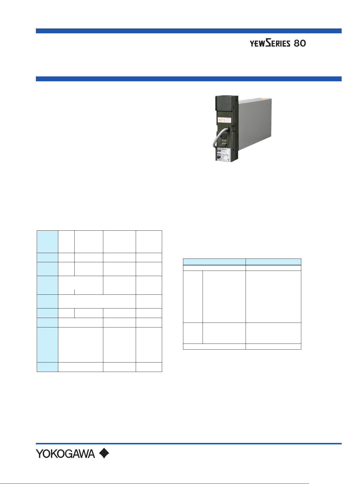
Model STED (Style S)
mV, Temperature and Potentiometer/
Voltage Converter
GS 01B04J01-02E
n GENERAL
The Model STED Converter accepts a mV DC,
thermocouple, RTD or potentiometer signal, converts
and normalizes it, provides isolation, and outputs 1
to 5 V DC and 4 to 20 mA DC signals. Two types
are prepared for the STED converter: xed input
type that is xed to mV DC, thermocouple, RTD
or potentiometer, and universal input type that can
select input type from mV DC, thermocouple or RTD.
Burnout function is provided as standard for each
type.
With the VJ77 Parameter Setting Tool you can do the
following:
· Read/write all parameters at once
· Save read parameters to a le
· Copy parameters to other devices of the same model
and sux code (only with style code R or S).
n STANDARD SPECIFICATIONS
Input Signals
mV DC
Thermocouple
Input
Signal
Type
Minimum
Span
Maximum
Span 100 mV 62 mV
Max. Zero
Elevation
Measuring
Range
Measurement
unit
Input
Resistance
Source
(leadwire)
Resistance
Input
Overload
*1: Thermocouple JIS C 1602、IEC 60584-1 (ITS-90)
TypeK, T, E, J, R, S, B, N, W3
*2: RTD JIS C 1604, IEC 60751 (ITS-90) Pt100
JIS C 1604: 1989, DIN (IPTS-68) Pt100
JIS C 1604: 1989, JPt100
JIS C 1604: 1981, Pt50 JIS C 1604
Input
3 mV 3 mV 10°C
Whichever is the smaller,
within three times the
span or
±50 mV ±25 mV
See table of Measuring Ranges
mV
1 MΩ (Power on)
4 kΩ (Power o)
Up to 500 Ω
Up to ± 4 V DC – –
Note 1: ASTM E988 Standard: W97Re3-W75Re25
(tungsten97% rhenium3%-tungsten75% rhenium25%)
Note 2:ASTM E988 Standard: W95Re5-W74Re26
(tungsten95% rhenium5%-tungsten74% rhenium26%)
(*1)
Input
shown on the right.
°C, K, °F
(*4)
(PT50/Pt100)
500°C (JPt100)
Within ve
times the span
(temperature)
(*6)
°C, K, °F
No greater than
input span (°C) X
0.4 Ω or 10 Ω per
wire, whichever is
the smaller.
Each leadwire
resistance must
be equal.
(Note 1)
RTD Input
3-wire
Current at
0.2 mA DC
650°C
– –
, W5
(*2)
(*3)
(*6)
(*5)
(Note 2)
Potentiometer
Up to 50
% of total
resistance
50 % or
more of total
resistance
Maximum 10
Ω per wire
Each leadwire
resistance
must be
equal.
Input
3-wire
Voltage at
0.5 V DC
80 Ω
2000 Ω
Ω
*3: When used with BARD-300 or BARD-700, the minimum span
is 30°C (60°C for Pt50). The minimum span for Pt50 is 20°C.
(BARD-300 and BARD-700 are safety barriers of YOKOGAWA.)
*4: When used with BARD-200 or BARD-600, the internal
resistance of BARD (235 Ω ± 15 Ω) is not included.
(BARD-200 and BARD-600 are safety barriers of YOKOGAWA.)
*5: When used with BARD-300 or BARD-700, the internal
resistance of BARD (130 Ω ± 3 Ω) is not included.
(BARD-300 and BARD-700 are safety barriers of YOKOGAWA.)
*6: When specify the option code “/FCAL”.
For universal input type, select one input type from
mV DC, thermocouple or RTD.
Measuring Ranges for Each Input
Type Measuring Ranges
mV –50 to 150 mV
(*1)
TC
RTD
Potentiometer
*7: For STED-7 type only
*8: For STED-4 type only
*9: Total resistance
Type K
Type T
Type J
Type E
Type B
Type R
Type S
Type N
Type W3
Type W5
(*2)
JPt100
Pt50
Pt100 (ITS-90)
Pt100 (IPTS-68)
(*8)
–200 to 1200°C
–200 to 350°C
0 to 750°C
–200 to 800°C
600 to 1700°C
0 to 1600°C
(*7)
(*7)
(*7)
0 to 1600°C
–200 to 1200°C
0 to 2000°C
0 to 2000°C
–200 to 510°C
–200 to 649°C
(*7)
–200 to 850°C
–200 to 660°C
100 to 2000 Ω
Output Signals
Output: 1 to 5 V DC (two outputs)
4 to 20 mA DC (one output)
Load Resistance:
2 kΩ or more (1 to 5 V DC output)
750 Ω or less (4 to 20 mA DC output)
(*9)
GS 01B04J01-02E
©Copyright Sep. 2001(MC)
14th Edition Jan. 2021(YK)

(Thermocouple output change/°C near 0°C)
(Thermocouple output change/°C at measurement temperature)
K =
2
BRAIN Communication Function
Sets each parameter, monitors input/output values, and
adju
sts input/output using a PC (VJ77) or the JHT200
Handy Terminal*.
Burnout Function (UP/DOWN/OFF)
Fixed input type: Selection by the jumper switch.
Universal input type: Selection by the parameter.
Calibration
mV DC Input:
Linearity for mV DC and output
Thermocouple Input/RTD Input:
Linearity for temperature and output
Potentiometer Input:
Linearity for resistance value and output
Adjustment Range for Zero and Span
mV DC Input/Thermocouple Input/RTD Input:
±5% of span
Potentiometer Input:
±10% of span
How to Adjust
Fixed input type:
Adjustment by push switch on the front.
Universal input type:
Adjustment using a PC (VJ77) or the
*: When connecting a PC (VJ77) or the JHT200
JHT200 Handy Terminal*.
Handy Terminal, the adapter for modular-jack
(model E9786WH) is required. When using the
BT200 BRAIN Terminal of YOKOGAWA Electric
Corporation, the communication cable of 5-pin
connector type (model F9182EE) and the adapter
for modular-jack (model E9786WH) are required.
n MOUNTING AND APPEARANCE
Mounting: Indoor rack mounting
Wiring
Signal wiring: ISO M4 size (4mm) screws on
Power and Ground wiring
100 V version: JIS C 8303 two-pole plug with
Cable length: 300 mm
Power supply terminal type (option
220 V version: CEE 7 VII (CENELEC standard)
Power supply terminal type (option
External Dimensions:
Weight: 1.7 kg (including rack-mounting case)
terminal block
earthing contact (IEC A5-15,
UL458)
code /TB)
plug (option code /A2ER)
Cable length: 300 mm
code /A2TB)
(Height x Width x Depth from the
mounting face)
180 x 48 x 300 (mm)
n STANDARD PERFORMANCE
Accuracy: ±0.5% of span
<For Thermocouple>
Note that for thermocouple input, add the reference
junction compensation accuracy to the accuracy
above.
Reference Junction Compensation Accuracy
For temperatures 0°C and over:
For temperatures below 0°C:
Reference junction compensation is not performed
for type B.
<For Thermocouple>
±0.5% of span or ±0.1°C, whichever is greater
Burnout Time: 1 minute or less
Maximum Power Consumption
DC voltage: 24 V DC, 75 mA
AC voltage: 100 V AC, 5.5 VA
220 V AC, 7.0 VA
However, there are the following conditions
for TC and RTD inputs.
±0.5°C (except for Types R and S)
±1°C (for Types R and S)
Multiply accuracy for temperatures
over 0°C by K, where
n POWER SUPPLY AND ISOLATION
Power Supply Rated Voltage:
100 V version:
24-110 VDC
100-120 VAC
220 V version:
135-300 VDC
200-240 VAC
Power Supply Input Voltage: AC/DC both usage
100 V version: DC drive 20 to 130 V, no polarity
AC drive 80 to 138 V, 47 to 63 Hz
220 V version: DC drive 120 to 340 V, no polarity
AC drive 138 to 264 V, 47 to 63 Hz
Insulation Resistance
Between I/O terminals and Ground:
100 MΩ/ 500 V DC
Between Power and Ground:
100 MΩ/500 V DC
Dielectric Strength
Between I/O terminals and Ground:
500 V AC for 1 minute.
Between Power and Ground:
1000 V AC for 1 minute (100 V version)
1500 V AC for 1 minute (220 V version)
, -10 %, +10 %, 100 mA
, -10 %, +10 %, 50/60 Hz, 8.0 VA
, -10 %, +10 %, 20 mA
, -10 %, +10 %, 50/60 Hz, 10.0 VA
All Rights Reserved. Copyright © 2001, Yokogawa Electric Corporation
GS 01B04J01-02E
Jan.12, 2021-00

3
n NORMAL OPERATING CONDITIONS
Ambient Temperature: 0 to 50°C
Ambient Humidity: 5 to 90% relative humidity
(non-condensing)
Operating environment: Area free of hydrogen sulde
gas and other corrosive
gases and dust and where
the device is not exposed to
sea breeze or direct sunlight.
Continuous vibration: (at 5 to 9 Hz) Half amplitude of
1.5 mm or less
(at 9 to 150 Hz) 4.9m/s
2
or less,
1 oct/min for 90 minutes each
in the three axis directions
Impact: 49 m/s
2
or less, 11 ms, 3 axes, 6 directions, 3
times each
Installation altitude: 2,000 m or less above sea level
Warm-up time: 15 minutes or more after the power is
turned on
n TERMINAL CONNECTIONS
Terminal arrangement
OUT
K
J
HFDCB
A
Terminal
Designation
A +
B C +
D F +
H J
K
Do not connect to the output terminal when the terminal is not in use.
Output 1 (1 to 5 V DC)
Output 3 (4 to 20 mA DC)
Output 2 (1 to 5 V DC)
n TRANSPORT AND STORAGE
CONDITIONS
Temperature: -25 to 70°C
Temperature change rate: 20°C per hour or less
Humidity: 5 to 95%RH (no condensation)
n OPTIONS
/NHR: Without rack case (internal unit only)
/FBP: Power supply fuse bypass
/LOCK: Power supply plug with lock
/WSW: With spring washer
/REK: Mount to same line with EK series rack
/TB: With power supply terminal
/A2TB: 220V version with power supply terminal
/A2ER: 220V version with power supply plug
/FCAL: Fahrenheit range
Description
Terminal
Designation
1 +
3
5
1
2
4
6
8
7
IN
2 - 2 2
3 3 3
4 4 4
5 5 5
6
7 7 7
8 8 8
For STED-7 type, select one input from mV DC, thermocouple or RTD.
Description
STED-1 and STED-2 STED-3 STED-4
mV DC input or
thermo- couple
input
(RJC block
installation terminal)
Terminal
Designation
Description
1 1
6 6
A
B
B
RTD
input
Terminal
Designation
Description
0%
CENTER
100%
Potentiometer
input
All Rights Reserved. Copyright © 2001, Yokogawa Electric Corporation
GS 01B04J01-02E
Jan.12, 2021-00

n EXTERNAL DIMENSIONS
Power supply plug type
4
180
Cable length: 300 mm
No zero and
span adjustment
push switches
for STED-7 type.
48
Trigonometry
Unit: mm
General tolerance = ±(value of tolerance class IT18 based on JIS B 0401-2016) / 2
Power supply terminal type(option /TB or /A2TB)
136
22
30052
F01.ai
52
180
No zero and
span adjustment
push switches
for STED-7 type.
48
Power supply
terminal block
L N
Trigonometry
Unit: mm
General tolerance = ±(value of tolerance class IT18 based on JIS B 0401-2016) / 2
All Rights Reserved. Copyright © 2001, Yokogawa Electric Corporation
71 300
Power and Ground Terminal connection
(Connection screw: M4)
Symbol
Description
+
L
-
N
Power supply
Ground
GS 01B04J01-02E
136
22
F02.ai
Jan.12, 2021-00

Power supply terminal type(option /REK)
5
200
2-ø7
190
5
52
No zero and
span adjustment
push switches
for STED-7 type.
32 136
48
Power supply
terminal block
L N
71 300
Power and Ground Terminal connection
(Connection screw: M4)
Symbol
Description
+
L
-
N
Power supply
Ground
Trigonometry
Unit: mm
General tolerance = ±(value of tolerance class IT18 based on JIS B 0401-2016) / 2
F03.ai
All Rights Reserved. Copyright © 2001, Yokogawa Electric Corporation
GS 01B04J01-02E
Jan.12, 2021-00

n MODEL AND SUFFIX CODES
Model Sux Codes Option Codes Descriptions
STED mV, Temperature and Potentiometer/Voltage Converter
Input
Signal
Number of Inputs 1 1 input
Sux Code 0 Always 0
Auxiliary Codes
STED-110: “-MV”
STED-210: “-TK” to “-TS”
STED-310: “-PA” to “-PD”
STED-410: “-RS”
STED-710: “-UN”
Style Code *S Style S
Option Codes
-1
-2
-3
-4
-7
(*1) (*2) (*3)
-MV
-TK
-TT
-TJ
-TE
-TB
-TR
-TS
-PA
-PB
-PD
-RS
-UN
/NHR
/FBP
/LOCK
/WSW
/REK
/TB
/A2TB
/A2ER
/FCAL
mV DC input
Thermocouple input
RTD input
Potentiometer input
Universal input (mV, TC, RTD input)
mV DC
Type K (ITS90, JIS C1602)
Type T (ITS90, JIS C1602)
Type J (ITS90, JIS C1602)
Type E (ITS90, JIS C1602)
Type B (ITS90, JIS C1602)
Type R (ITS90, JIS C1602)
Type S (ITS90, JIS C1602)
JPt100 (JIS’89)
Pt50 (JIS’81)
Pt100 (ITS-90, JIS C1604)
Potentiometer
Universal input (mV, TC, RTD input)
Without rack case
Power supply fuse bypass
Power supply plug with lock
With spring washer
Mount to same line with EK series rack
With power supply terminal
220V version with power supply terminal
220V version with power supply plug
Fahrenheit range
6
6
*1: /LOCK, /REK, /TB, /A2TB, and /A2ER cannot be specied together.
*2: /FBP, /A2TB, and /A2ER cannot be specied together.
*3: When setting the temperature unit with “deg F”, specify the option code /FCAL.
n ORDERING INSTRUCTIONS
Specify the following when ordering:
1. Model, sux code and auxiliary code, and optional sux code, if necessary.
2. Specication of input: Mandatory specication
(1) Fixed-to-mV DC input type
(2) Fixed-to-Thermocouple input type (except for Types N, W3 and W5)
(3) Fixed-to-RTD input type
(4) Fixed-to-Potentiometer input type
(5) Universal input type
3. Burnout selection: Optional specication
Measuring range and unit e.g. 0 to 10 mV DC
Measuring range and unit e.g. 0 to 300 °C
Measuring range and unit e.g. 0 to 300 °C
• Total resistance and unit (R
• Resistance at 0% point and unit (R
• Resistance at 100% point and unit (R
e.g. Resistance of Potentiometer R
T Ω)
0 Ω)
100 Ω)
T = 500 Ω, R0 = 50 Ω, R100 = 450 Ω
• Input type (Select input type from mV DC, thermocouple or RTD.)
• When mV DC input is selected:
Measuring range and unit e.g. 0 to 10 mV DC
• When thermocouple input is selected (see table of Measuring Ranges on page 1):
Thermocouple type e.g. Type K
Measuring range and unit e.g. 0 to 300 °C
• When RTD input is seleccted (see table of Measuring Ranges on page 1):
RTD type e.g. Pt100
Measuring range and unit e.g. 0 to 100 °C
Select from UP, DOWN or OFF.
If not specied: OFF
All Rights Reserved. Copyright © 2001, Yokogawa Electric Corporation
Subject to change without notice.
GS 01B04J01-02E
Jan.12, 2021-00
 Loading...