

Page 1

Technical
TI 34P02K35-02E
TI 34P02K35-02E
Information
STARDOM
Engineering Guide (FCN-500/FCN-RTU)
© Copyright Apr. 2016 (YK)
1st Edition Apr.28.2016 (YK)
3rd Edition Jun. 6.2018 (YK)
Page 2

Blank Page
Page 3

i
IMPORTANT
Introduction
About this manual
This engineering guide is intended as a guide for system engineering of a
STARDOM system (FCN-500, FCN-RTU) based on given specifications.
It supplements the information contained in the following documents, which
are required for STARDOM engineering, and explains precautions and
pointers, following the engineering workflow sequence.
Related Documents
- GS 34P02Q02-01E FCN-RTU Autonomous Controller Functions
- GS 34P02Q03-01E FCN Autonomous Controller Functions (FCN-500)
- IM 34P02P25-01E NPAS POU – Overview
- IM 34P02Q01-01E STARDOM FCN/FCJ Guide
- TI 34P02A13-01E FCN-500 Technical Guide
- TI 34P02A14-01E FCN-RTU Technical Guide
- TI 34P02K13-02E STARDOM FCN-500/FCN-RTU
Primer – Fundamental
- TI 34P02K25-01E STARDOM Network Configuration Guide
- TI 34P02Q91-01E STARDOM FCN/FCJ Installation Guide
Notation in this document:
- The term “FCN-500” refers to the autonomous controllers with NFCP501/NFCP502
CPU module.
- The term “FCN-RTU” refers to the low power autonomous controllers with
NFCP050 CPU module.
All Rights Reserved. Copyright © 2001, Yokogawa Electric Corporation TI 34P02K35-02E Jun. 6, 2018-00
Page 4

ii
Copyrights and Trademarks
Copyrights
The copyrights of this document belong to Yokogawa Electric Corporation.
No part of this document may be transferred, sold, distributed (including delivery via
a commercial PC network or the like), or registered or recorded on videotapes.
Trademarks and Licensed Software
- STARDOM is a trademark.
- Company names and product names included in this document are trademarks
or registered trademarks of their respective owners.
- Registered trademarks or trademarks are not denoted with the ‘TM’ or ‘®’ mark
in this document.
TI 34P02K35-02E Jun. 6, 2018-00
Page 5

iii
TI 34P02K35-02E 3rd Edition
STARDOM
Engineering Guide (FCN-500/FCN-RTU)
CONTENTS
Introduction ................................................................................................ i
Copyrights and Trademarks .................................................................... ii
CONTENTS ............................................................................................... iii
1. Overview ........................................................................................... 1
2. Basic Design and Function Design ................................................ 3
2.1 Checking Hardware Specification ............................................................ 3
2.1.1 Current Consumption of FCN-500 and FCN-RTU Unit ................... 3
2.1.2 Checking Operation Specifications of I/O Modules ........................ 6
2.1.3 Checking Automatic Loading of I/O Modules .................................. 6
2.1.4 Measures for Duplexing .................................................................. 7
2.2 Pre-Application Creation Checklist .......................................................... 9
2.2.1 Checking Revisions of FCN-500, FCN-RTU and Tools .................. 9
2.2.2 Checking FCN-500, FCN-RTU Control Application Size .............. 12
2.2.3 Checking FCN-500, FCN-RTU Performance ................................ 13
2.2.4 Determining FCN-500, FCN-RTU Scan Cycle .............................. 15
2.2.5 Retentive Variable (Retain Data) Considerations ......................... 18
2.2.6 Time Synchronization .................................................................... 23
3. Hardware Setup .............................................................................. 25
3.1 Resource Configurator Setting ............................................................... 25
3.2 Setup in Web Browser ............................................................................. 27
4. Control Application Creation ......................................................... 29
4.1 Using Logic Designer Setup ................................................................... 29
4.1.1 Selecting a Template for a New Project ........................................ 29
4.1.2 Control Task Setup ........................................................................ 31
4.1.3 Multi-tasking .................................................................................. 34
4.1.4 Specifying Target FCN/FCJ........................................................... 35
4.1.5 Multi-resource Project ................................................................... 37
4.1.6 Application Size ............................................................................. 38
4.2 Application Programming Languages ................................................... 40
4.2.1 Programming Languages Supported by Logic Designer .............. 40
4.2.2 Selecting a Programming Language ............................................. 41
TI 34P02K35-02E Jun. 6, 2018-00
Page 6

iv
4.3 Principles of Application Creation .......................................................... 42
4.3.1 Principles of Application Creation ................................................. 42
4.3.2 Example of a Simple Application ................................................... 42
4.3.3 Bottom-up Application Creation .................................................... 45
4.4 Application Creation Know-how ............................................................. 46
4.5 Network Templates ................................................................................... 47
4.6 Application Encapsulation ...................................................................... 48
4.6.1 Features of Application Encapsulation .......................................... 48
4.6.2 Procedure for Creating a POU ...................................................... 50
4.6.3 Modifying Logic of a POU ............................................................. 54
4.7 Handling Compile Errors and Warnings ................................................ 58
4.8 Precautions About Downloading ............................................................ 60
4.8.1 Offline Download and Online Download ....................................... 60
4.8.2 Downloading Boot Project and Source ......................................... 62
4.8.3 Detailed Description of Download Dialog ..................................... 62
4.8.4 Importance of Boot Project ........................................................... 64
4.8.5 Importance of Source .................................................................... 65
4.9 Control Application Backup .................................................................... 66
5. Function Test (Debugging) ............................................................ 69
5.1 Equipment Used for Testing .................................................................... 69
5.1.1 Precautions of Testing When Using In-house Equipment ............. 70
5.1.2 Precautions of Testing When Using FCN/FCJ Simulator .............. 73
5.1.3 Precautions of Testing When Using Target Equipment ................. 75
5.1.4 Precautions of Migrating Testing from In-house Equipment to
Target Equipment .......................................................................... 77
5.2 Unit Test and Combination Test .............................................................. 79
5.3 Unit Test Precautions ............................................................................... 80
5.3.1 Pre-unit Test Checklist .................................................................. 80
5.3.2 Unit Test Methodology ................................................................... 81
5.3.3 Unit Test Know-how ...................................................................... 83
5.4 Combination Test Precautions ................................................................ 86
5.4.1 Combination Test Prerequisites .................................................... 86
5.4.2 Equipment Used for Combination Test ......................................... 86
5.4.3 Checking Log Files of FCN-500, FCN-RTU .................................. 87
5.4.4 System Failure Test ....................................................................... 87
5.5 Checking CPU Load and Application Size ............................................. 92
5.5.1 Checking CPU Load...................................................................... 92
5.5.2 Checking Application Size ............................................................. 93
TI 34P02K35-02E Jun. 6, 2018-00
Page 7

v
5.6 Logic Designer’s Debug Mode ................................................................ 95
5.6.1 Switching to Debug Mode ............................................................. 96
5.6.2 Basic Operation in Debug Mode ................................................... 99
5.6.3 Disconnecting I/O .......................................................................... 99
5.6.4 Entering and Checking Values of Device Label Variables .......... 101
5.7 Software Wiring ...................................................................................... 106
5.7.1 Overview of Software Wiring ....................................................... 106
5.7.2 Software Wiring Creation and Precautions ................................. 107
5.7.3 Precautions When Creating Software Wiring ............................. 109
5.8 Using Loop Check Tool ........................................................................... 110
5.8.1 Values Displayed in Loop Check Tool .......................................... 111
5.8.2 Locating Problems Using Loop Check Tool ................................. 112
6. User Acceptance Test (UAT) ........................................................ 114
6.1 Pre-UAT Checklist ................................................................................... 114
6.1.1 UAT Prerequisites ........................................................................ 114
6.1.2 UAT Implementation Guidelines................................................... 115
6.2 Items Requiring Prior Explanation to Users ......................................... 11 6
6.2.1 Differences in Equipment Used from Actual System ................... 116
6.2.2 Differences between Process I/O and Software Wiring ............... 117
6.2.3 Equipment Communicating with FCN-500, FCN-RTU ................. 11 7
7. System Delivery Precautions ...................................................... 118
7.1 System Delivery Checklist ...................................................................... 119
7.1.1 System Delivery Prerequisites ..................................................... 119
7.1.2 Forms of Delivery ......................................................................... 119
7.2 Delivery for New System ....................................................................... 121
7.2.1 Pre-Delivery Preparation ............................................................. 121
7.2.2 Control Application Backup ......................................................... 122
7.2.3 System Delivery .......................................................................... 123
7.3 Delivery for System Expansion ............................................................. 124
7.4 Delivery for System Modification .......................................................... 125
7.4.1 Pre-Delivery Preparation and Application Backup ...................... 125
7.4.2 System Delivery .......................................................................... 125
7.4.3 Preparation for On-site Installation ............................................. 125
7.4.4 On-site Installation ...................................................................... 126
7.5 Procedure Instruction Sheet and Rehearsal ....................................... 127
8. Detailed Description ..................................................................... 128
8.1 Checking Operation Specifications of I/O Modules ............................ 128
8.1.1 Checking Operation Specification of Analog/Digital Input .......... 128
8.1.2 Checking Operation Specification of Analog/Digital Output ........ 130
8.1.3 Checking Specification of Pulse Input......................................... 132
8.1.4 Checking Specification of Pulse Width Output ........................... 133
8.2 Checking Specification of Serial Communication .............................. 135
TI 34P02K35-02E Jun. 6, 2018-00
Page 8

vi
8.3 Precautions about Multi-tasking .......................................................... 137
8.4 Criteria for Selecting Programming Languages in Logic Designer .. 141
8.4.1 Selection Criteria for FBD, LD and ST ........................................ 141
8.4.2 Selecting between FBD and LD .................................................. 149
8.4.3 Combining FBD, LD and ST ....................................................... 150
8.4.4 Selecting between SFC and Stepped FBD or LD ....................... 152
9. Advanced Engineering ................................................................ 156
9.1 General Application Development Know-how ..................................... 156
9.1.1 Variable Definitions ..................................................................... 156
9.1.2 Local Variables versus Global Variables ..................................... 157
9.1.3 _RB and _BOOL Suffix Variables of Device Label Variables ...... 160
9.1.4 Execution Order of Control Application ....................................... 162
9.1.5 Inter-FCN/FCJ Communication Concept .................................... 169
9.1.6 How to Create User Data Types ................................................. 175
9.1.7 Jump, Connector and Return Functions ..................................... 178
9.1.8 Cross References ....................................................................... 182
9.1.9 Specifying Retain Data and OPC Property ................................. 185
9.1.10 Getting FCN-500, FCN-RTU Time .............................................. 186
9.1.11 Precautions When Using Terminal EN of Functions ................... 187
9.1.12 Logic for Saving Retain Data ...................................................... 190
9.1.13 Comparing Logic Designer Projects ........................................... 192
9.1.14 Avoidance of the Error during Execution .................................... 193
9.2 Know-how in Use of NPAS_POU .......................................................... 194
9.2.1 Scan Cycle and Control Cycle .................................................... 194
9.2.2 How to Detect Mode, Status and Alarm ...................................... 197
9.2.3 NPAS_POU Status Propagation ................................................. 202
9.2.4 Blocked NPAS_POU Status Propagation ................................... 207
9.2.5 Selection of Timers and Counters ............................................... 210
9.2.6 Engineering Parameters .............................................................. 211
Appendix 1 STARDOM Engineering Flow Chart ............................... 214
Revision Information ................................................................................. i
TI 34P02K35-02E Jun. 6, 2018-00
Page 9
<1. Overview>
1
TI 34P02K35-02E
Jun. 6, 2018-00
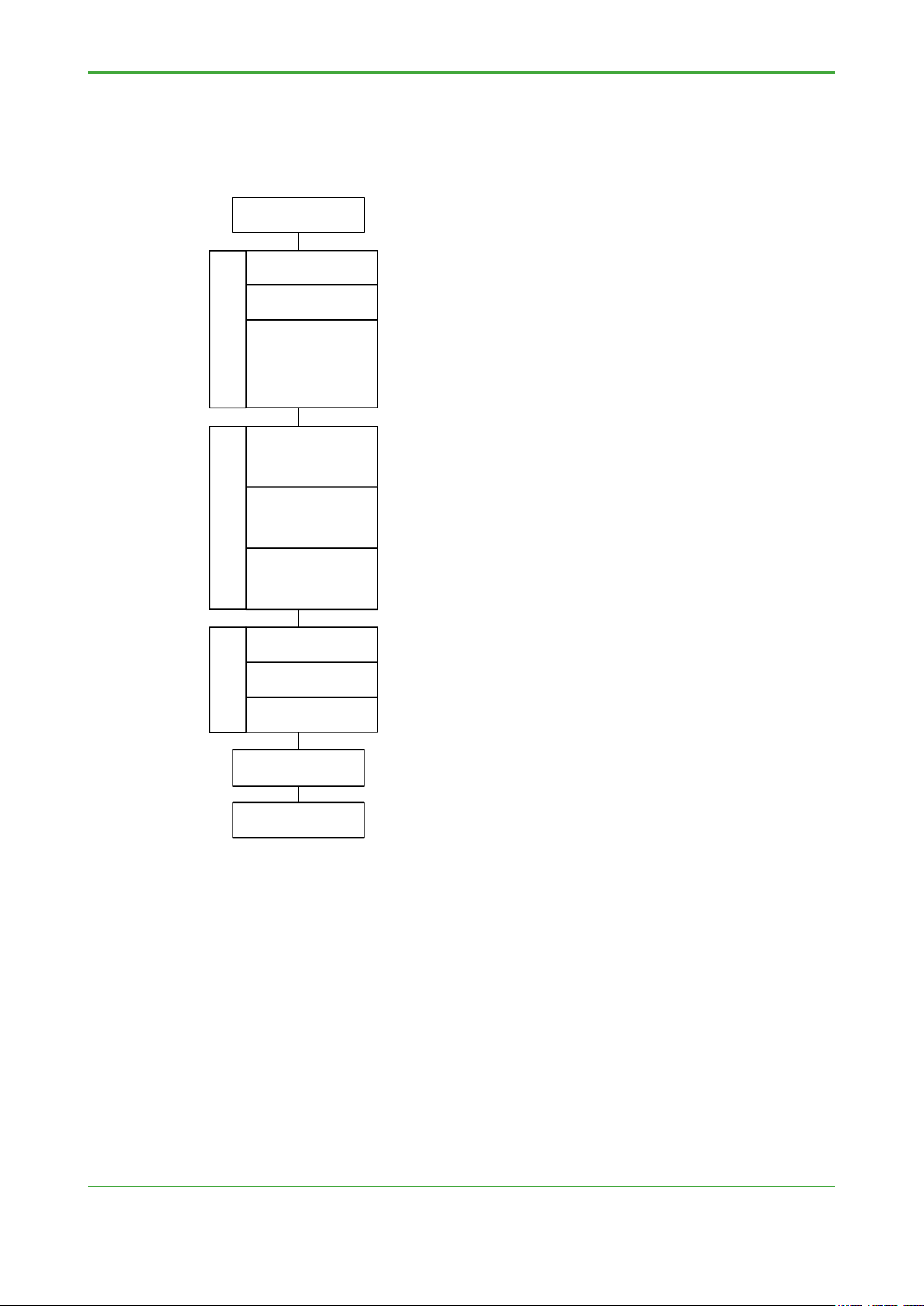
Check require-
ment spec.
User acceptance
test (UAT)
System delivery
Unit test
Integration test
System test
Detailed function
design of
application
software
Check requirement
spec.
Check system
configuration
- Verify that the requirement specification can be implemented using
the STARDOM system.
- Verify that the system configuration allows implementation of the
requirement specification.
- Based on the requirement specification, prepare basic specifications
for FCN/FCJ control applications, operation/monitoring applications
and communication functions.
- Based on basic functions, perform detailed design of each
application and prepare functional specification.
- Based on function specification, create applications.
- In unit test, check individual applications.
- In integration test, combine applications already tested in unit tests
and test the integrated STARDOM system as a whole.
- In system test, combine external equipment and control panels with
the STARDOM system, and perform function test, including
communication tests.
- Verify along with customer that the designed/created application
satisfies the function specification.
- After completion of UAT, deliver STARDOM system.
FCN/FCJ control
applications
Operation and
monitoring
applications
Communication
applications
Basic design and
function design
Application creationFunction test
1. Overview
STARDOM engineering can be divided into phases as shown in the diagram
below.
This engineering guide is intended as a guide for system engineering of a
STARDOM system based on given specifications. For this purpose, it describes
the precautions and checklist for each of the engineering phases after
specifications are confirmed, including basic design and function design,
application creation, function test, user acceptance test (UAT) and system
delivery.
This engineering guide focuses on FCN/FCJ control applications.
Details on the functions and use of the FCN-500 and FCN-RTU controller and
individual application programming tools can be found in their respective
instruction manuals (IM) and Technical Information (TI). Wherever necessary, this
manual will refer the reader to these documents for details on functions and
usage.
Page 10

Blank Page
Page 11

<2. Basic Design and Function Design>
3
TI 34P02K35-02E
Jun. 6, 2018-00
2. Basic Design and Function Design
The first thing to do in STARDOM engineering is to check whether a given
customer specification can be implemented using the hardware, application
programming tools, APPFs (application portfolios), and licenses provided
with the system.
2.1 Checking Hardware Specification
Review specifications for the hardware given in GS and IM documents to
confirm whether specification requirements are achievable.
2.1.1 Current Consumption of FCN-500 and FCN-RTU Unit
Calculate the current consumption of each FCN unit, and check that it does not
exceed the rated output current of the power supply module.
● Rated Output of Power Supply Module
The rated output current of the FCN-500 power supply module is given by:
System power supply: 0 A to 7.8 A
Analog field power supply: 4 A (max)
SEE ALSO
Chapter A1.3, “Power Supply Module” of IM “STARDOM FCN/FCJ Guide”
The rated output current of the FCN-RTU power supply module is given by:
NFPW426: System power supply: 0 A to 2.4 A
Analog field power supply: 0.54 A (max)
NFPW441: System power supply: 0 A to 7.8 A
Analog field power supply: 4 A (max)
SEE ALSO
Chapter A2.3, “Power Supply Module (NFPW426, NFPW444)” of IM “STARDOM FCN/FCJ Guide”
The power supply module mounted on a unit supplies power only to that unit so
the current consumption of each unit must be kept below the rated output
described above.
Page 12
<2. Basic Design and Function Design>
4
TI 34P02K35-02E
Jun. 6, 2018-00
● Calculating Current Consumption of an FCN Unit
The current consumption of the system power supply of an FCN unit can be
obtained by summing the current consumption values of the base module, as well
as the CPU modules, I/O modules, and E2 bus/SB bus modules installed on the
base module.
If I/O modules requiring analog field supply are mounted in the unit, the current
consumption of the analog field supply of the FCN unit should be calculated
additionally. The system power supply current consumption and analog field
supply current consumption values of individual modules given in the “STARDOM
FCN/FCJ Guide” can be used for these calculations.
An example of current consumption calculation
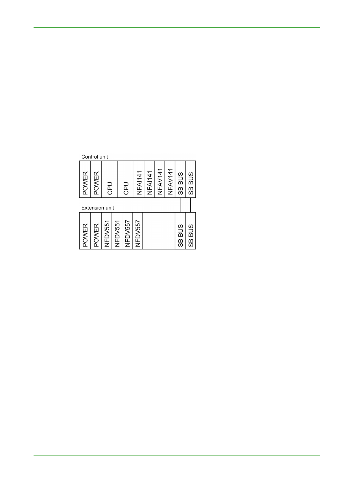
This example calculates the current consumption of the control unit, as well as,
that of the extended unit, shown in the figure below.
- Calculating current consumption of control unit
System power supply
Current consumption of NFCP501 modules : 1200 mA×2 =2400 mA
Current consumption of NFAI141 modules : 310 mA×2 = 620 mA
Current consumption of NFAV141 modules : 350 mA×2 = 700 mA
Current consumption of SB bus repeat modules : 500 mA×2 =1000 mA
Total: 4720 mA < rated output current of 7.8A
Analog field power supply
Current consumption of NFAI141 : 450mA×2 = 900mA
Total: 900mA < rated output current of 4A
NFAV141 and SB bus repeat modules do not require analog field power and
are thus excluded from the calculation. (E2 bus interface module does not
require analog field power too)
- Calculating current consumption of extension unit
System power supply
Current consumption of NFDV551 modules : 700mA×2 = 1400mA
Current consumption of NFDV557 modules : 550mA×2 = 1100mA
Current consumption of SB bus repeat modules : 500mA×2 = 1000mA
Total: 3500mA < rated output current of 7.8A
Page 13

<2. Basic Design and Function Design>
5
TI 34P02K35-02E
Jun. 6, 2018-00
Analog field power supply
Current consumption of NFDV551 modules : 60mA×2 = 120mA
Current consumption of NFDV557 modules : 60mA×2 = 120mA
Total: 240mA
(For digital output cards, 24Vmust be supplied to each module)
SB bus repeat module does not require analog field power and are thus
excluded from the calculation. (E2 bus interface module does not require
analog field power too)
In this example, the current consumption of the system power supply, as well as
the current consumption of the analog field power supply, of both the control unit
and the extension unit, are below the rated output of the power supply modules so
there is no problem.
● I/O Modules Requiring Analog Field Power Supply
In the power consumption calculation example given above, some of the I/O
modules of the FCN-500 and FCN-RTU units require analog field power supply.
SEE ALSO
Section A1.13.3 "Field Power Supply" of IM “STARDOM FCN/FCJ Guide."
Any of such I/O modules, when used, require 24 V DC to be supplied to the power
supply module, in addition to the power supply used for control. Check the
hardware specification for 24 V DC power supply.
Page 14

<2. Basic Design and Function Design>
6
TI 34P02K35-02E
Jun. 6, 2018-00
2.1.2 Checking Operation Specifications of I/O Modules
Compare the operation specification of each I/O module against the requirement
specification to ensure that requirements can be met.
For more details, see Section 8.1, "Checking Operation Specifications of I/O
Modules;" Section 8.2, "Checking Serial Communication Specification" of Chapter
8, "Detailed Description," as well as the "STARDOM FCN/FCJ Guide."
2.1.3 Checking Automatic Loading of I/O Modules
Operation settings, device label names and all other configuration information of
I/O modules and communication modules are saved in the on-board flash
memory of the FCN-500 and FCN-RTU. Using Resource Configurator, whether to
automatically load configuration information into a new I/O module when an I/O
module is replaced can be specified.
If automatic loading is enabled, configuration information stored on the flash
memory is loaded and a replacement I/O module begins operations
automatically provided if the same model name I/O module being replaced.
Otherwise, confirmation information is not loaded automatically.
If automatic loading is disabled, configuration information stored on the flash
memory is not loaded automatically regardless of the model of the
replacement module.
In such case, redefine and download settings using the Resource Configurator
and rebooting the FCN-500 or FCN-RTU is required.
Page 15

<2. Basic Design and Function Design>
7
TI 34P02K35-02E
Jun. 6, 2018-00
2.1.4 Measures for Duplexing
Within a STARDOM system, the following components can be duplexed:
CPU of FCN-500
Power supply module of FCN-500 or FCN-RTU (used long base module only)
SB bus of FCN-500
Control network (control LAN) of FCN-500
Communication application
Check precautions described below for duplexed system components.
● FCN-500 Operation When Configured with Duplexed CPU
The operation specification and precautions applicable when the CPU of an FCN500 is duplexed are given in the following IM and TI documents:
Section B1.3.3, “Precautions on the Creation of Control Applications” of IM
“STARDOM FCN/FCJ Guide”
Chapter C2, “Duplex CPU Module (FCN-500)” of IM “STARDOM FCN/FCJ
Guide”
Section 7.2, “Operation using Duplex FCN CPU Modules" of TI “FCN-500
Technical Guide”
● FCN-500 and FCN-RTU Operation When Configured with Duplexed
Power Supply Module
Duplexing of the power supply module can be achieved by simply installing two
power supply modules on a long base module.
SEE ALSO
For details on the operation specification of an FCN-500 configured with duplexed power supply
module, see Section 3.1.2, “Power Supply Module” of TI “FCN-500 Technical Guide,” Section 3.1.2,
“Power Supply Module” of TI “FCN-RTU Technical Guide.”
● FCN-500 Operation When Configured with Duplexed E2 Bus/SB Bus
Duplexing of the E2 bus/SB bus can be achieved simply by configuration using
Resource Configurator.
SEE ALSO
For details on the operation specification of an FCN-500 configured with duplexed SB bus, see
Section 3.4, “SB Bus Repeat Module for FCN” of TI “FCN-500 Technical Guide.”
Page 16

<2. Basic Design and Function Design>
8
TI 34P02K35-02E
Jun. 6, 2018-00
● FCN-500 Operation and Precautions Regarding Duplexed Control
Network
For details on the operation specification and precautions applicable to a
STARDOM system configured with duplexed control network, see:
Section D2.2.2, “Control Network Duplexed Configuration” of IM “STARDOM
FCN/FCJ Guide”
Section 2.6 "Duplexing Control Network" of TI “STARDOM Network
Configuration Guide”
• Diagnostic communication interval
In a duplexed control network, diagnostic frames are transmitted periodically
through multicast communication.
If two successive diagnostic frame transmissions are unsuccessful, system
network failure is assumed, and control network switchover is performed.
One diagnostic frame is transmitted and one receive processing is performed
for each duplexed device within each cycle. When there are many duplexed
devices, the CPU load increases proportionally due to increased receive
processing of diagnostic frames. The diagnostic communication interval is
defined as 500 ms by default and can be lengthened as appropriate if many
duplexed devices are present on the network.
SEE ALSO
For details, see Section 2.6.1, “The Duplexed Network Function Provided on STARDOM” of TI
“Network Configuration Guide.”
● Operation and Precautions Regarding Duplexed Communication
Application
To implement duplexed communication with non-STARDOM equipment such
as FA-M3, third-party PLCs, and remote I/O, a communication application
must include logic for executing a transmission path switchover when a
communication error is detected.
SEE ALSO
For more details, see Section 2.6.2, “Duplexing Communications Using an Application” of TI
“Network Configuration Guide.”
Page 17

<2. Basic Design and Function Design>
9
TI 34P02K35-02E
Jun. 6, 2018-00
2.2 Pre-Application Creation Checklist
This section covers checking items on application programming tools,
application size, etc, before creating applications.
2.2.1 Checking Revisions of FCN-500, FCN-RTU and Tools
Before programming applications, check the revisions of the FCN/FCJ Basic
Software and each tool to be used in subsequent engineering. These include:
- FCN/FCJ Basic Software (stored on the system card)
- Resource Configurator
- Logic Designer
- Various application portfolios
The revision of the FCN/FCJ Basic Software should match the revision of the
CPU module (on-board flash memory).
SEE ALSO
For details on how to check the revision of the system card, see "● Revision of System Card Used”
of Section 5.1.1, “Precautions of Testing when Using In-house Equipment.”
● For New System Implementation
When implementing a new system, using the latest versions of the FCN/FCJ
Basic Software and tools listed above is recommended.
If application development is to be carried out using in-house development
equipment instead of the target equipment, upgrade the FCN-500, FCN-RTU,
Logic Designer and all software tools to the latest versions before starting
application creation.
● For System Modification
When modifying an existing application using in-house development equipment,
whether revisions of the FCN/FCJ Basic Software and the various tools listed
above of the in-house equipment match those of the existing system is needed to
be checked.
When carrying out engineering for system modification using in-house equipment
having revisions later than the existing system, beware of using new system
functions not supported in the existing system. Otherwise, the application may,
despite thorough testing on in-house equipment, fail to be downloaded to the
existing system or, even if successfully downloaded to the existing system, fail to
run or fail to run correctly.
Moreover, even if a function used in the modified application is present on the
existing system, its operation specification may be different because of functional
enhancements included in the revision upgrade so that the modified application
may behave differently when tested on in-house equipment and when executed
on the existing system after delivery.
Page 18

<2. Basic Design and Function Design>
10
TI 34P02K35-02E
Jun. 6, 2018-00
● For System Expansion
STARDOM allows intermixing of FCN-500 and FCN-RTU of different revisions
within a system. When implementing system expansion through addition of a new
FCN-500 and FCN-RTU to an existing system, consider whether to use the latest
revision for the new FCN-500 and FCN-RTU or to match the existing system
revision.
Consider the pros and cons described below, and decide whether to use the latest
revision for the new FCN-500, FCN-RTU and intermix different FCN-500, FCNRTU revisions within the system, to standardize revisions throughout the system
by downgrading the new FCN-500, FCN-RTU to match the existing system
revision, or to standardize to the latest revision throughout the system by
upgrading the existing system.
• Using the latest revision
In this case, all supported functions can be used.
However, beware that the operation specifications of some functions may
have changed due to functional enhancements included in the revision
upgrade so that the expanded system may behave differently from the existing
system. Furthermore, system revision control may be more tedious with
intermixing of FCN-500 and FCN-RTU s of different revisions.
• Matching the existing revision
In this case, the new FCN-500 and FCN-RTU will behave the same as the
existing system but new functionality included in the latest revision will not be
available. However, system revision control will be easier with a standardized
FCN-500 and FCN-RTU revision throughout the system.
The FCN-500 is used R4.02 or later.
● Procedure for System Downgrade
The procedures are essentially the same for downgrading and upgrading the
revision of in-house equipment to match the revision of an existing system for the
purpose of system modification or system expansion engineering.
When upgrading, use the DVD-ROM for the latest system revision; when
downgrading, use the DVD-ROM for the required system revision instead.
Observe the following precautions for downgrading the FCN/FCJ Basic Software.
• Precautions when downgrading FCN/FCJ Basic Software
FCN-500 can not be downgrading before than R4.02.
FCN-RTU can not be downgrading before than R2.10.
To downgrade a system, follow essentially the same procedure for system
upgrade by decompressing the Basic Software stored on the DVD-ROM for
the required revision to the PC, and then issuing an “FcxRevup” command at
the command prompt but include a “-s” option.
Page 19

<2. Basic Design and Function Design>
11
TI 34P02K35-02E
Jun. 6, 2018-00
If you execute the plain “FcxRevup” command without the “-s" option, as is
usually done when performing a revision upgrade, configuration information
stored on the flash memory will be retained after command execution. This
may cause an error if the existing configuration information cannot be
interpreted by the older revision after system downgrade. Therefore, when
downgrading a system, execute the "FcxRevup” command with the “-s" option
to perform a clean upgrade along with initialization of configuration
information.
● Checking Service Packs and Service Releases
Service releases or service packs may have been published for some system
revisions.
For new system implementation, after installing the latest system revision, check
for the presence of published service releases and service packs, and apply them
as required. Similarly, after having upgraded or downgraded the revision of inhouse equipment to match the existing system, check whether any service
releases and service packs have been previously applied to the existing system,
and apply them accordingly to the in-house equipment.
Page 20

<2. Basic Design and Function Design>
12
TI 34P02K35-02E
Jun. 6, 2018-00
2.2.2 Checking FCN-500, FCN-RTU Control Application Size
Estimate the size of an FCN500 or FCN-RTU control application from the
requirement specification and ensure that there is no problem.
SEE ALSO
For details on how to estimate the size of an application, see Section 4.5.2, “Calculation of Control
Application Capacity" of TI "FCN-500 Technical Guide," Section 4.5.2, “Calculation of Control
Application Capacity" of TI "FCN-RTU Technical Guide."
Estimate the control application size by estimating the ADLST size and retain data
size as described in TI “STARDOM Technical Guide.”
To investigate the utilization of application resources, calculate the respective
utilization rates of ADLST capacity of retain data capacity, and take the larger of
the two values as the system-wide utilization rate.
The checking items described in this section is based on calculated values, which
should be verified by checking the actual control application size during function
test.
SEE ALSO
For details, see Section 5.5.2, “Checking Application Size.”
• For projects using NPAS POUs
Projects using NPAS POUs usually exceed the ADLST size limit (if ever it is
exceeded) before exceeding the retain data size limit.
Therefore, first estimate the ADLST size, and if it is within the 4MB upper limit,
you can assume that there is no application size problem.
You can also use the ADLST utilization as an indicator of the utilization of the
control application.
• For projects not using NPAS POUs
For projects not using NPAS POUs, the ADLST size and retain data size
depend on how many variables are specified with OPC property and RETAIN
property during engineering.
In this case, estimate both ADLST size and retain data size and if both values
are within their respective upper limits, it can be assumed that there will be no
application size problem.
Furthermore, use the larger of the ADLST and retain data utilization rates as
an indicator of the utilization rate of the control application.
Page 21

<2. Basic Design and Function Design>
13
TI 34P02K35-02E
Jun. 6, 2018-00
NPAS_POU's execution time
Control task interval
CPU load (%) =
x 100%
2.2.3 Checking FCN-500, FCN-RTU Performance
Estimate the execution time of an FCN-500 or FCN-RTU control application from
the requirement specification and determine the CPU load.
SEE ALSO
For details on how to estimate performance, see Section 4.5.3, “Confirmation of Performance" of TI
"FCN-500 Technical Guide", Section 4.5.3, “Confirmation of Performance" of TI "FCN-RTU Technical
Guide".
The checking items described in this section is based on calculated values, which
should be verified by checking the actual CPU load during function test.
SEE ALSO
For details, see Section 5.5.1, “Checking CPU Load."
● Calculating Execution Time and CPU load of Control Application
The method for estimating the execution time of a control application depends on
whether the project uses NPAS POUs.
• For projects using NPAS POUs
For a project using NPAS POUs, determine the execution time as described in
the above-mentioned TI document, and calculate the CPU load using the
following formula:
• For projects not using NPAS POUs
The above-mentioned TI document does not describe how to calculate the
execution time of a project not using NPAS POUs. This is because the
execution time of non-NPAS_POU blocks are very short and hence need not
be considered during the estimation phase.
TIP
In the CPU function specification description of the GS document “FCN Autonomous Controller
Functions (FCN-500)” or “FCN-RTU Low Power Autonomous Controller Functions”, the execution
speed is given as:
FCN-500s Execution speed: Approx. 10 µs per kilosteps in an IL program
FCN-RTUs Execution speed: Approx. 50 µs per kilosteps in an IL program
This means that about 10 µs (FCN-500) or 50 µs (FCN-RTU) is required to process 1 kilosteps of an
IL program block.
Each function such as AND or OR coded in IL is equivalent to 3 steps.
Therefore, the execution time of 1000 functions is about 30 µs (FCN-500) or about 150 µs (50 µs x
3, FCN-RTU).
Based on this calculation, about 195,000 functions (FCN-500) or about 65,000 functions (FCN-RTU)
can be processed within 10 milliseconds.
Page 22
<2. Basic Design and Function Design>
14
TI 34P02K35-02E
Jun. 6, 2018-00
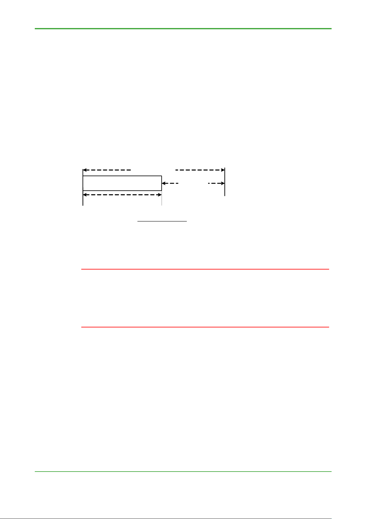
IMPORTANT
Execution time
Scan cycle
Idle time
Execution time
Scan cycle
CPU load ≤ 60%
Executes communication
● Recommended CPU Load
The following FCN-500 and FCN-RTU functions are executed during CPU idle
time:
- Ethernet communications of FCN-500 and FCN-RTU
- Communication with VDS/ASTMAC data server
- Inter- FCN-500 and FCN-RTU communication
- Various inter-device communications such as Modbus communications
using Ethernet or serial communications
- Operation or setup from Logic Designer or Resource Configurator
- Duolet function
- Downloading of boot project and source
To allow such processing, it is recommended that the CPU load be kept at 60% or
lower.
and Duolet functions
CPU load (%) =
x 100 %
The CPU load calculation described in this section considers only the execution
time of the control application. In an actual system, execution time also includes
CPU module and I/O module access time. Therefore, consider a CPU load slightly
higher than the value estimated here.
The I/O module access time varies with the number of I/O modules and normally
ranges between several milliseconds to 20 milliseconds.
Page 23

<2. Basic Design and Function Design>
15
TI 34P02K35-02E
Jun. 6, 2018-00
2.2.4 Determining FCN-500, FCN-RTU Scan Cycle
As described in the previous section 2.2.3, “Checking FCN-500 and FCN-RTU
Performance,” it is recommended that CPU load be kept at 60% or lower.
Check that the estimated CPU load is 60% or lower, and there is no problem with
the scan cycle stated in the requirement specification if applicable. If the CPU
load exceeds 60%, investigate rectification measures.
● Setting Range for Scan Cycle
The scan cycle of the FCN-500 can be set to a value between 5 ms and 32760
ms in 5 ms increments. The scan cycle of the FCN-RTU can be set to a value
between 10 ms and 32760 ms in 10 ms increments. When setting the scan cycle
to 4 seconds or longer, note the precautions described later.
● When a Required Scan Cycle is Stated in Requirement Specification
If a scan cycle is stated in the requirement specification, use the stated value to
estimate the CPU load and check that it is 60% or lower. If the CPU load exceeds
60%, consider whether it can be reduced using the methods described later.
● When no required scan cycle is stated in requirement specification
If no scan cycle is stated in the requirement specification the engineer is given the
responsbility, determine the scan cycle from the execution time of the control
application estimated as described in Section 2.2.3, “Checking FCN-500 and
FCN-RTU Performance.”
● Example for Determining Scan Cycle
If engineer is asked to decide on the scan cycle, use Logic Designer’s default
scan cycle of 100 ms as a baseline consideration.
Example 1: When estimated control execution time is 20 ms
Estimated CPU load = 20 ms/100 ms = 20%
Based on the estimated CPU load of 20%, even considering the time for
accessing I/O modules, the CPU load is expected to be below the
recommended limit of 60%. Therefore, the scan cycle of 100 ms should be
fine.
Example 2: When estimated control execution time is 50 ms
Estimated CPU load = 50 ms/100 ms = 50%
The estimated CPU load of 50% is below the recommended limit of 60%.
However, if the time for accessing I/O modules is taken into consideration, the
CPU load is expected to approach 60%, or even exceed 60% if many I/O
modules are installed.
In this example, we should look into reducing the CPU load using the methods
described hereafter.
If the scan cycle is set to 100 ms, download the application early on in application
creation to check that there is indeed no CPU load problem.
Page 24
<2. Basic Design and Function Design>
16
TI 34P02K35-02E
Jun. 6, 2018-00
Execution time
Scan cycle
CPU load
70 ms
100 ms
70%
70 ms
200 ms
35%
IMPORTANT
● Ways for Reducing CPU Load
Consider the ways described below for reducing CPU load.
• Lengthen the scan cycle
By lengthening the scan cycle, CPU load can be reduced even if the execution
time remains unchanged.
After changing the scan cycle, which is the most fundamental setting affecting
FCN-500 and FCN-RTU operation, always check that control is not adversely
affected.
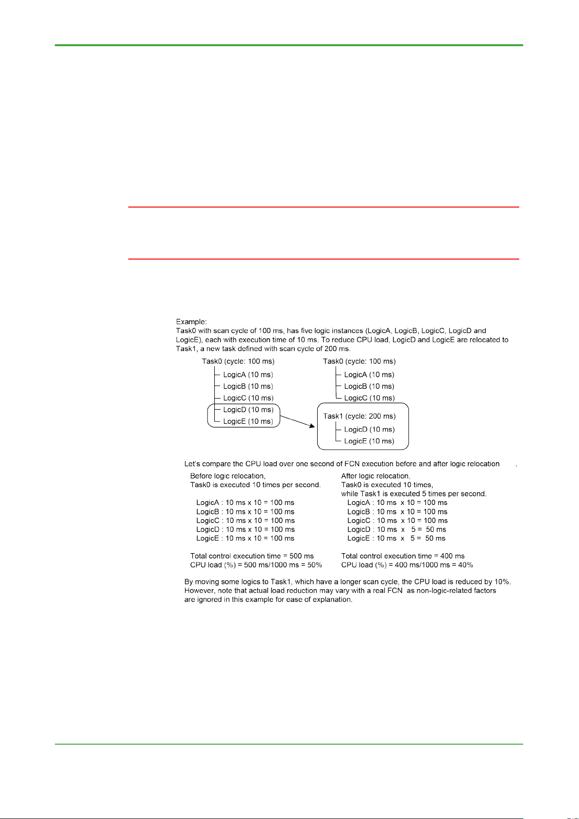
• Define a task with long control cycle and move the application
For an application that can tolerate a long control cycle, define a task with a
longer cycle and move. By doing so, it reduces the overall CPU load.
Page 25

<2. Basic Design and Function Design>
17
TI 34P02K35-02E
Jun. 6, 2018-00
Control Cycle
Windup Time
100 ms
3 seconds
500 ms
15 seconds
1000 ms (= 1 minute)
30 seconds
2000 ms (= 2 minutes)
60 seconds (= 1 minute)
● Precautions When Using a Long Scan Cycle
• When scan cycle is 4 seconds or longer
Analog/digital output modules are defined with line access loss time of 4
seconds.
If the scan cycle is 4 seconds or longer, the interval between FCN-500 or
FCN-RTU CPU accesses of the output modules will be 4 seconds or longer.
Depending on individual setting, an output module may assume that a CPU
error has occurred and perform output fallback.
SEE ALSO
For details, see Section 8.1.2, "Checking Operation Specification of Analog/Digital Output” of
Chapter 8, “Detailed Description.”
• About windup of NPAS POUs
For NPAS POU, after an FCN-500 or FCN-RTU reboot, windup processing is
executed for 30 scan cycles before control computation begins.
As the windup time is proportional to the scan cycle, lengthening the scan
cycle delays the starting of control computation after an FCN-500 or FCN-RTU
boot.
Page 26

<2. Basic Design and Function Design>
18
TI 34P02K35-02E
Jun. 6, 2018-00
2.2.5 Retentive Variable (Retain Data) Considerations
Retain data of the FCN-500 and FCN-RTU may reside in the following locations:
- Non-volatile memory (factory setting)
- Volatile memory
- Flash memory
Based on the requirement specification, decide whether retain data is to reside in
volatile memory or non-volatile memory, as well as the procedure for saving retain
data to the flash memory.
SEE ALSO
For details on considerations of retain data in FCN-500 and FCN-RTU, see Section 4.3.5, “Retentive
Variables” of TI “FCN-500 Technical Guide,” Section 4.3.5, “Retentive Variables” of TI “FCN-RTU
Technical Guide.”
● Retain Data Residing in Memory
Retain data can be stored in either volatile memory or non-volatile memory using
Resource Configurator and is always resident in one of these locations.
By default factory setting, retain data is resident in non-volatile memory.
- Non-volatile memory
Retain data, when resident in non-volatile memory, is retained by a backup
battery even if the FCN-500 or FCN-RTU is powered off.
- Volatile memory
Data, including retain data, resident in the volatile memory is cleared when the
FCN-500 or FCN-RTU is powered off.
The management of retain data is rather different depending on whether it resides
in volatile or non-volatile memory.
● Saving Retain Data to Flash memory
Retain data residing in memory can also be backed up to the flash memory either
manually by an operator or by executing a save instruction from an application.
An operator can manually execute the backup using “Save Retain Data” from the
FCN/FCJ “Maintenance Menu” or, equivalently, set global variable
"GS_RETAIN_SV_SW” to TRUE in Logic Designer’s DEBUG mode.
Depending on the conditions present after an FCN-500 or FCN-RTU reboot, retain
data may be restored from the flash memory so saving retain data to the flash
memory is an important aspect of retain data management.
SEE ALSO
For details on executing a save instruction from an application, see Section 9.1.12, “Logic for Saving
Retain Data” of Chapter 9, "Advanced Engineering ".
In the FCN-500, the retain data is stored in the flash memory, and can be saved on the SD card. For
details, refer to D3.4 "Backup of all data to SD card (FCN-500)" of IM “STARDOM FCN/FCJ Guide”
Page 27

<2. Basic Design and Function Design>
19
TI 34P02K35-02E
Jun. 6, 2018-00
TIP
In subsequent description, the term "retain data on the flash memory" refers to retain data which
was current as at the time when it was saved to the system card but not necessarily the most up-todate.
For instance, if retain data was saved a week ago, “retain data on the flash memory" would be one
week old.
● Behavior of Retain Data when FCN-500 or FCN-RTU Power is Off/On
1. If retain data is resident in non-volatile memory
As described earlier, retain data residing in non-volatile memory is retained even
after the FCN-500 or FCN-RTU is powered off. When the FCN-500 or FCN-RTU
is powered on, the system reboots using retain data in the non-volatile memory so
retain data persistency is guaranteed.
However, under certain circumstances, retain data in the non-volatile memory
may not be restored. Instead, all retentive variables are first initialized to their
initial values after power on. If retain data has been previously saved to the flash
memory, that data is restored. Otherwise, the FCN-500 or FCN-RTU reboots with
all initial variable values. Some circumstances under which retain data in the nonvolatile memory will not be restored are listed below.
• If the structure of retain data of the application at startup does not match
the structure of retain data in the non-volatile memory
If the control application running before power off is inconsistent with the boot
project on the flash memory on the number, data type or some other aspect of
retain data, retain data in the non-volatile memory will not be restored after
power on.
• If the backup battery was removed
If the backup battery is removed when power is off, retain data, like all other
data residing in the non-volatile memory, will be lost and hence cannot be
restored at power up.
• If the CPU module or FCJ has been replaced
If the CPU module or FCJ is replaced, retain data residing in the non-volatile
memory of the hardware naturally cannot be restored.
2. If retain data is resident in volatile memory
Retain data stored in volatile memory is lost when the FCN-500 or FCN-RTU is
powered off.
After power on, all retentive variables are first initialized to their initial values. If
retain data has been previously saved to the flash memory, that data is restored.
Otherwise, the FCN-500 or FCN-RTU reboots with all initial variable values.
Page 28

<2. Basic Design and Function Design>
20
TI 34P02K35-02E
Jun. 6, 2018-00
● Behavior of Retain Data in FCN/FCJ Start Mode
Performing offline download to FCN-500 or FCN-RTU from Logic Designer stops
control on the FCN-500 or FCN-RTU. However, as power supply is not
interrupted, retain data, even if resident in volatile memory, retain their data. As
such, the behavior of retain data after data download in the FCN/FCJ start mode
is the same regardless of whether retain data is resident in volatile or non-volatile
memory.
1. If FCN/FCJ is warm started
1.1 If there is no change in retain data area
If there is no change in the retain data area, control is started using retain data
values current before offline download, even if the control application has been
changed.
1.2 If retain data structure has been changed
If the number or data type of retain data has been changed so that the retain
data structure is modified, retain data in the memory can no longer be used.
SEE ALSO Point 1 of TIP below
In this case, all retentive variables are first initialized to their initial values. If
retain data has been previously saved to the flash memory, control is restarted
using that data.
SEE ALSO Point 2 of TIP below
If no retain data is saved on the system card, the FCN-500 or FCN-RTU is
rebooted with initial values for retentive variables.
Page 29
<2. Basic Design and Function Design>
21
TI 34P02K35-02E
Jun. 6, 2018-00
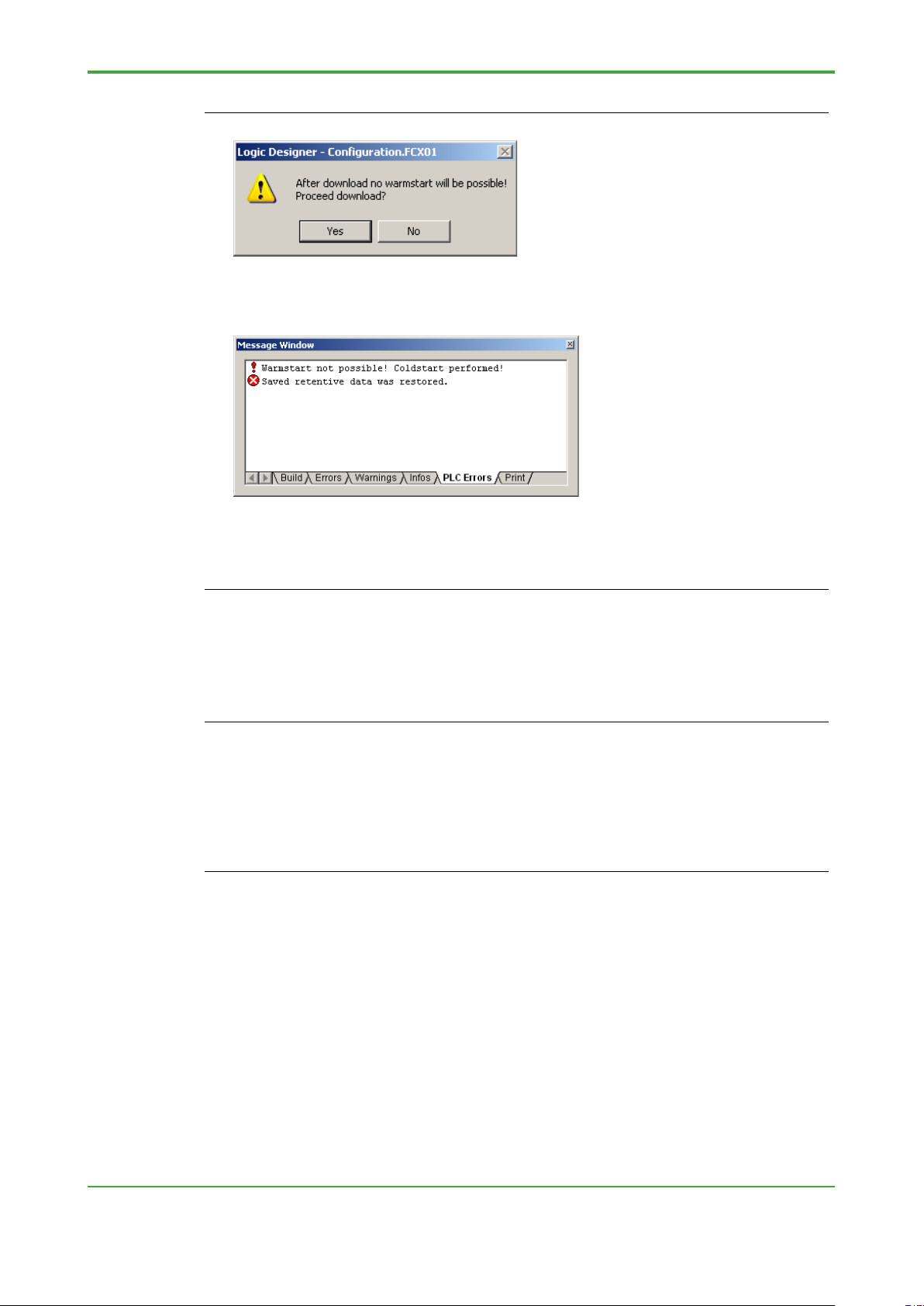
TIP
1. In the case of 1.2 described above, the following dialog is displayed before offline download:
This message indicates that warm start using retain data residing in the memory will not be
possible after downloading. It does not mean that warm start, in itself, is not allowed.
2. In this case, performing a warm start after completion of offline download generates the following
PLC error:
The first line of the message means that cold start was performed as warm start using retain
data in memory was not possible. The second line of the message means that the FCN-500 or
FCN-RTU was restarted using retain data saved on the flash memory.
From these two error messages, retain data saved on the flash memory was restored by a warm
start after an offline download is understood.
2. If FCN/FCJ is cold started
After a cold start, the FCN-500 or FCN-RTU initializes all variables and start
controlling. In other words, all retentive variables are initialized by a cold start.
TIP
The retain data structure will be changed by the following events:
- Adding or deleting an NPAS POU having one or more access parameters or engineering
parameters specified as retain data
- Specifying a non-retentive variable as a retentive variable or vice versa
- Changing the data type of a variable specified as retain data
The behavior of retain data on the FCN-500 or FCN-RTU start mode described above applies
similarly when the FCN-500 or FCN-RTU is stopped from Logic Designer’s Application Control
dialog,and then restarted without performing downloading.
Page 30

<2. Basic Design and Function Design>
22
TI 34P02K35-02E
Jun. 6, 2018-00
● Behavior of Retain Data on Online Download
Even if a modification involves a change in the retain data area, persistency of
retain data is guaranteed so long as the modification is online downloaded. Newly
added retentive variables, however, will be set to initial values.
● Relationship between Initial Value and Retained Value
After an FCN-500 or FCN-RTU warm start, even if initial values are specified for
retain dat, their retained values take precedence.
● Summary
By default setting, FCN-500 or FCN-RTU is configured so that retain data is
resident in non-volatile memory. As such, you can first review the specification on
this basis.
Data resident in non-volatile memory retain their values even after the FCN-500
or FCN-RTU is powered off because of a backup battery. These retained values
are restored at the next FCN-500 or FCN-RTU power on. In this way, the most upto-date data values are always maintained so keeping retain data resident in nonvolatile memory is the usual practice.
However, even if retain data is made resident in non-volatile memory, we
recommend saving retain data to the flash memory regularly as a safeguard
against unexpected situations where data retained in memory cannot be used. In
addition to saving retain data manually, saving data regularly using a control
application is also recommended.
SEE ALSO
For details, see Section 9.1.12, “Logic for Saving Retain Data” of Chapter 9, “Advanced
Engineering.”
If a backup of retain data is saved on the flash memory, in case of event that data
retained in non-volatile memory cannot be used for whatever reason, retained
data values as at the time of saving will be restored from the system card. by
doing so, it avoids the worst-case scenario where all retain data variables are
initialized.
Compared to keeping retain data resident in non-volatile memory, keeping retain
data reside in volatile memory enables a shorter execution time, and hence a
shorter scan cycle for FCN-500 or FCN-RTU operation. However, if the FCN-500
or FCN-RTU is powered off and on again, retain data values before power off is
lost and retain data values are always restored from the flash memory.
To prepare for unexpected contigency, save retain data to the flash memory
regularly, and also by manually whenever retain data is modified.
SEE ALSO
For details on scan cycle, see Section 2.2.4, “Determining FCN-500 and FCN-RTU Scan Cycle.”
Page 31

<2. Basic Design and Function Design>
23
TI 34P02K35-02E
Jun. 6, 2018-00
2.2.6 Time Synchronization
The FCN-500 or FCN-RTU allows time synchronization among external devices
supporting SNTP (Simple Network Time Protocol).
SEE ALSO
For details on time synchronization of FCN-500 or FCN-RTU, see:
- Section B1.9.4, “Time Synchronization Function” of IM “STA R DOM FCN/FCJ Guide”
- Section 2.3.3, “Time Synchronization Function” of TI “FCN-500 Technical Guide”
- Section 2.3.3, “Time Synchronization Function” of TI “FCN-RTU Technical Guide”
● For FCN-500 Running as SNTP Server
After setting through FCN-500 maintenance page, the FCN-500 time
synchronization server automatically runs and starts time reporting. Setting for
SNTP server is done through FCN-500 maintenance page. The following file is
modified to start SNTP sever.
However, the FCN-500 cannot provide highly accurate time reporting as its
reported time includes internal timer error of -17.5 to +12 seconds/day.
1. JEROS Basic Setting File (DOUNUS.PRP)
It specifies whether to start the SNTP server function. This setting is for only
FCN-500 only. Specify YES to start SNTP Server.
Setting item: Start the SNTP server function (SntpServer)
SntpServer = YES use the SNTP server function
SntpServer = NO not use the SNTP server function,
default value
SEE ALSO
For details of JEROS basic setting file, see online-help.
● For FCN-500 or FCN-RTU Running as SNTP Client
If the FCN-500 or FCN-RTU runs as an SNTP client. To setup from the
FCN/FCJ maintenance homepage to enable the FCN-500 or FCN-RTU to
receive reported time values from an SNTP server (as an SNTP client) and
perform time synchronization accordingly.
From the FCN/FCJ maintenance homepage, time synchronization settings are
implemented at the following two locations.
1. JEROS Basic Setting File (DOUNUS.PRP)
Configure for the use of SNTP client function.
2. SNTP Setting File (S NT P.PRP)
SEE ALSO
For details of JEROS basic setting file, see online-help.
Page 32

Blank Page
Page 33

<3. Hardware Setup>
25
TI 34P02K35-02E
Jun. 6, 2018-00
IMPORTANT
3. Hardware Setup
After reviewing and deciding on a desired FCN-500 and FCN-RTU hardware
configuration as described in Chapter 2, perform the actual FCN-500 and FCNRTU hardware setup by running Resource Configurator and by accessing the
FCN/FCJ maintenance homepage using a generic web browser.
3.1 Resource Configurator Setting
Among the hardware configuration items reviewed and described in Chapter 2, the
following items are configured using Resource Configurator:
- I/O module operation
- Enabling/disabling of automatic loading of I/O modules
- Duplexed operation
- Enabling/disabling of hardware backup of retain data
SEE ALSO
- Section 2.1.2,”Checking Operation Specifications of I/O Modules”
- Section 2.1.3,”Checking Automatic Loading of I/O Modules”
- Section 2.1.4,”Measures for Duplexing”
- Section 2.2.5,”Retentive Variable (Retain Data) Considerations”
Do not turn off the power to the FCN-500 and FCN-RTU controller while
downloading Resource Configuration.
It will take up to three minutes to complete the download operation.
For details on the Resource Configurator and how to use the Resource Configurator
Editor, read “STARDOM FCN-500/FCN-RTU Primer – Fundamental”(TI 34P02K1302) and the Resource Configurator online help documentation.
Page 34

<3. Hardware Setup>
26
TI 34P02K35-02E
Jun. 6, 2018-00
● Precautions When Using FCN-500 or FCN-RTU with No Actual I/O
Modules
Resource configurator R4.20 or later can maintain unimplemented I/O module
definition.
If FCN-500 or FCN-RTU is not installed with the required I/O modules and new
hardware configuration us downloaded using Resource Configurator R4.10 or
earlier, existing I/O module configuration already defined will be overwritten and lost.
As an example, consider the following scenario.
An engineer defines the required device labels and I/O settings for target equipment
installed with the required I/O modules, and downloads the project to the FCN-500
or FCN-RTU.
However, as application creation and debugging is to be carried out using an inhouse FCN-500 or FCN-RTU, he relocates the CPU module on the target FCN-500
or FCN-RTU to the in-house FCN-500 or FCN-RTU and reboots the FCN-500 or
FCN-RTU.
When the engineer connects to the in-house FCN-500 or FCN-RTU using Resource
Configurator at this stage, the system reads a state of no I/O module.
The engineer then downloads this information using Resource Configurator,
resulting in I/O module information being overwritten, and information defined
previously is lost permanently.
To prevent this, it is advisable not to modify hardware settings using Resource
Configurator when working with no I/O module installed or from using a different set
of I/O modules than what is currently defined in the configuration.
● Using Resource Configurator Editor
Resource Configurator works by first reading configuration information from a
running FCN-500 or FCN-RTU, and then downloading new configuration information
after it has been modified on a PC. As such, it cannot be used to perform hardware
setup without a running FCN-500 or FCN-RTU.
To perform hardware setup when an FCN-500 or FCN-RTU is not available, such as
in the early phase of engineering or in a job involving modification of an existing
system, use Resource Configurator Editor instead.
Settings defined using Resource Configurator Editor can be saved to a file, and
downloaded later using Resource Configurator when the FCN-500 or FCN-RTU is
available for connection.
Page 35

<3. Hardware Setup>
27
TI 34P02K35-02E
Jun. 6, 2018-00
3.2 Setup in Web Browser
Detailed setup and various FCN-500 or FCN-RTU operations can be achieved using
FCN/FCJ maintenance homepage through a generic web browser.
Among the hardware configuration items reviewed and decided as described in
Chapter 2, the following items can be configured by accessing the FCN/FCJ
maintenance homepage:
- Serial communication port
- Time synchronization
SEE ALSO
- Section 8.2, “Checking Serial Communication Specification (Serial Communication Port Settings)”
- Section 2.2.6, “Time Synchronization”
In addition to the above configuration items, setting system date and time, saving
retain data, read log files of the FCN-500 or FCN-RTU, reading various properties of
the FCN-500 or FCN-RTU , display CPU status and display resource configuration
can be achieved from the FCN/FCJ maintenance homepage.
SEE ALSO
For details on the operation and configuration items accessible on the maintenance homepage, see:
- Chapter B2, “Advanced Settings Using Web Browser“ of IM “STARDOM FCN/FCJ Guide”
- Section 4.1.6, “Settings of FCN/FCJ by Web Browser“ of TI “FCN-500 Technical Guide”
- Section 4.1.6, “Settings of FCN/FCJ by Web Browser“ of TI “FCN-RTU Tec h nical Guide”
Page 36

TI 34P02K35-02E
Jun. 6, 2018-00
Blank Page
Page 37

<4. Control Application Creation>
29
TI 34P02K35-02E
Jun. 6, 2018-00
4. Control Application Creation
Control applications executed by FCN-500 and FCN-RTU autonomous
controllers are created using Logic Designer and then downloaded to the
FCN-500 and FCN-RTU.
This chapter describes precautions on Logic Designer setup, as well as basic
principle, know-how and prohibitions on creating control applications.
For details on basic user operations of Logic Designer, see TI “STARDOM FCN500/FCN-RTU Primer – Fundamental" and the Logic Designer online help
documentation.
4.1 Using Logic Designer Setup
This section describes the required setup and selection using Logic Designer
before creating a control application, along with related precautions and
know-how information.
4.1.1 Selecting a Template for a New Project
When creating a new project using Logic Designer, select a project type from a list
of template projects.
For details on how to create a new project and select a template, see Section 4.1.2,
“Creating a New Project” of TI “STARDOM FCN-500FCN-RTU Primer –
Fundamental.”
● Template Types and Selection Criteria
When creating a new project, the project type can be selected from the following
three template projects.
• STARDOM FCX
This is the minimal template, which provides only system-defined functions and
function blocks. It does not include NPAS_POU, PAS_POU, serial
communication function blocks and function blocks for Foundation Fieldbus.
As such, select this template only when creating an application that uses neither
NPAS_POU nor PAS_POU.
• STARDOM FCN-500
It is the standard template for creating control application for the FCN-500.
Necessary functions for creating the control application has been prepared in
advance. (NPAS_POU, serial communication function block, function block for
Foundation Fieldbus, Turbomashinary, etc.)
If necessary, it is possible to add other library after creating a project.
Page 38

<4. Control Application Creation>
30
TI 34P02K35-02E
Jun. 6, 2018-00
• STARDOM FCX_A
It is the standard template for creating control application for the FCN-RTU.
Necessary functions for creating the control application has been prepared in
advance. (NPAS_POU, serial communication function block, function block for
Foundation Fieldbus, Turbomashinary, etc.)
If necessary, it is possible to add other library after creating a project.
● Adding Libraries
Logic Designer allows libraries to be added to a project to expand the available
functions.
Similarly, an application using an APPF can be created by installing the required
APPF from DVD-ROM to a PC running Logic Designer, and adding the relevant
libraries to the project.
Examples:
- To create an application using NPAS POUs, select the STARDOM FCX template
when creating the project, and then add the related NPAS_POU library.
Which library to add depends on the function to be aded. For details on the type of
library to be added and the procedure, see the online help documentation of each
function.
● Logic Designer Libraries and FCN-500, FCN-RTU Licenses
No license is required for adding a library to Logic Designer. In other words,
application development using a system function is allowed even if no license for
that function is registered in the FCN-500 or FCN-RTU.
However, a PLC error will be generated and the FCN-500 or FCN-RTU cannot run if
a project is downloaded to an FCN-500 or FCN-RTU without registering with the
required licenses for all functions used in the project.
When adding a library for functionality expansion, check that the required license is
registered in the FCN-500 or FCN-RTU .
SEE ALSO
Section 2.1.5, "Required Licenses”
Page 39

<4. Control Application Creation>
31
TI 34P02K35-02E
Jun. 6, 2018-00
4.1.2 Control Task Setup
Control applications created in Logic Designer are created by assigning to tasks and
turn into instances. This section describes task types and task settings.
● General Limitations of Control Tasks
All control tasks are subject to the following limitations.
• Limit on number of tasks
Up to 16 control tasks can be created for one FCN-500 or FCN-RTU. Running
only one control task on one FCN-500 or FCN-RTU is known as single-tasking,
while creating and running multiple control tasks concurrently on one FCN-500
or FCN-RTU is called multi-tasking.
• Task name
A task name consists of up to 7 alphanumeric and underscore (‘_’) characters
with the following restrictions:
- A task name cannot begin with a number.
- A task name cannot contain two contiguous underscore (‘_’) characters.
- A task name cannot end with an underscore (‘_’) character.
● Types of Control Tasks
There are three types of control tasks with different behaviors.
• Cyclic
A cyclic task is run at a specified interval, known as scan cycle. This task type is
used for most control applications.
• Default
A default task has the lowest execution priority among all control tasks. It is not
executed at fixed intervals. Instead, it is executed automatically when all other
control tasks are idle (not executing).
A default task is executed at variable execution intervals as its execution is
dependant on the operation of other control tasks. Hence, this task type is, in
general, not used in control applications.
• System
A system task is run when there is a change in the operating status of the FCN-
500 or FCN-RTU, or when an error is detected in the FCN-500 or FCN-RTU.
Page 40

<4. Control Application Creation>
32
TI 34P02K35-02E
Jun. 6, 2018-00
IMPORTANT
Execution triggers (status change or error) for a system tasks can be selected
from a list of predefined triggers.
System tasks are run only under specific FCN-500 or FCN-RTU conditions.
Hence, this task type is, in general, not used in control applications except for
some special-purpose applications.
As default and system task types are, in general, not used in control applications,
the description hereafter is limited to the cyclic task type.
Moreover, the term "control task" hereafter shall refers to a cyclic control task.
Page 41

<4. Control Application Creation>
33
TI 34P02K35-02E
Jun. 6, 2018-00
● Control Task Settings
The Task Settings dialog is used for specifying the execution interval, execution
priority, watchdog time and other settings of a control task.
For details on the relationship between the execution interval, priority and watchdog
time of a control task, and how these settings affect task execution, see Section
4.3.3, “Task Schedule” of TI “FCN-500 Technical Guide,” Section B4.3.3, “Task
Schedule” of TI “FCN-RTU Technical Guide.”
1. Execution interval of control task
Specify the execution interval of a control task in the [Interval] field on the Task
Settings dialog. The default execution interval for a new project is 100 ms. Modify it
according to the value decided as described in Section 2.2.4, ”Determining
FCN/FCJ Scan Cycle.”
2. Priority
When running multiple tasks concurrently on an FCN-500 or FCN-RTU, specify a
value (ranging from 0 to 31 in decreasing priority) for [Priority] on the task settings
dialog as the priority level of a task relative to other tasks during execution.
Assigning different priority values to individual tasks running in multi-tasking mode is
recommended.
3. Watchdog time
When the actual execution time of a control task exceeds the specified [Watchdog
Time], a watchdog error is generated and handled according to the setup described
in Section 4.1.4, “Specifying Target FCN/FCJ.”
Setting the watchdog time to 0 disables the watchdog timer.
Set the watchdog time to the same value as the control task execution interval as
described in Section 4.1.4, “Specifying Target FCN-500, FCN-RTU” is
recommended
4. Other Settings
The other settings on the Task Settings dialog including [Stack] and [Options] can be
left unchanged at default values.
Page 42

<4. Control Application Creation>
34
TI 34P02K35-02E
Jun. 6, 2018-00
4.1.3 Multi-tasking
This section describes the considerations and precautions for running multiple tasks
concurrently on an FCN-500 or FCN-RTU.
SEE ALSO
For details on the behavior of the FCN-500 or FCN-RTU when multiple tasks are created, see Section
4.3.3, “Task Schedule” of TI “FCN-500 Technical Guide,” Section 4.3.3, “Task Schedule” of TI “FCNRTU Technical Guide.”
● Considerations Multi-tasking
Two possible reasons for considering implementing multi-tasking are given below:
1. To c reate control tasks having different execution intervals in an attempt to
reduce CPU load of the FCN-500 or FCN-RTU. For details, see Section
2.2.4, “Determining FCN-500, FCN-RTU Scan Cycle.”
2. To c reate control tasks having the same execution interval and priority
level for sorting control tasks to be instantiated by function.
The FCN/FCJ runs without problems even with multi-tasking. However, in multitasking mode, tasks are processed alternately at intervals of 30 ms in a time-sharing
manner as described in TI “STARDOM Technical Guide” and this complicates desk
investigation of control applications.
Therefore, running one task per FCN-500 or FCN-RTU is generally recommended.
When deciding on control application execution, start with single-tasking and
consider multi-tasking only if it is necessary.
Even when considering creating multiple tasks so as to reduce the CPU load of the
FCN-500 or FCN-RTU, listed as the first reason above, first consider the option of
lengthening the execution interval of a single control task, and consider multi-tasking
only if the first option is disallowed by the requirement specification.
Creating multiple tasks having the same execution interval and priority for sorting
purpose, listed as the second reason above, is unnecessary.
Multi-tasking not only complicates system operation, it may also increase CPU load
due to processing for sharing such as shared access to I/O modules.
For these reasons, it is best to avoid splitting a single task into multiple tasks having
the same execution interval and priority.
● Precautions When Multi-tasking
Pay attention to some precautions when using multi-tasking.
SEE ALSO
For details on precautions when multi-tasking, see Section 8.3, “Precautions about Multi-tasking" of
Chapter 8, “Detailed Description."
Page 43

<4. Control Application Creation>
35
TI 34P02K35-02E
Jun. 6, 2018-00
4.1.4 Specifying Target FCN/FCJ
The following Target dialog is used for specifying the IP address of the FCN-500 or
FCN-RTU.
Besides the IP address, this dialog also displays a checkbox with the message “The
task aborts when the execution time of a task exceeds a watch dog time.”
The checkbox setting is explained below.
SEE ALSO
For details on how the above setting affects system behavior in the event of a watchdog error, see
Section 4.3.3, “Task Schedule” of TI “FCN-500 Technical Guide,” Section 4.3.3, “Task Schedule” of TI
“FCN-RTU Technical Guide."
For details on how to specify the IP address of an FCN-500 or FCN-RTU, see Section 4.1.3,
“Specifying Target FCN-500, FCN-RTU (by Specifying IP Address)" of “FCN-500/FCN-RTU Primer –
Fundamental.”
● Defining Task Behavior upon a Watchdog Error Event
How a control task behaves when its execution time exceeds the specified
watchdog time described in Section 4.1.2, “Control Task Setup” differs whether the
“The task aborts when the execution time...” checkbox described above is ticked or
not.
• Common behavior regardless of whether checkbox is ticked or not
If the watchdog time described in Section 4.1.2, "Control Task Setup” is set to a
value other than 0 ms, a watchdog error will be generated when the execution
time of a control task exceeds the preset value.
At the same time, a watchdog error will be logged in the log file on the FCN-500
or FCN-RTU.
• Behavior when checkbox is ticked
If the checkbox is ticked, execution of the associated task will be aborted at the
same time a watchdog error is generated. The control application associated
with the task also stops execution. Moreover, once aborted, execution of the task
will not be restarted until the FCN-500 or FCN-RTU is rebooted.
• Behavior when checkbox is not ticked
If the checkbox is not ticked, nothing happens when a watchdog error is
generated, and the control task continues execution.
Page 44

<4. Control Application Creation>
36
TI 34P02K35-02E
Jun. 6, 2018-00
IMPORTANT
The above description shows that if the “The task aborts when the execution time...”
checkbox is ticked, control computation of the FCN-500 or FCN-RTU will stop even
if only one watchdog error is generated.
To prevent this, untick the “The task aborts when the execution time...” checkbox.
● Watchdog Time Setting
On the other hand, monitoring task execution time using watchdog time provides
important diagnostic information about the current state of the system.
Therefore, set the watchdog time described in Section 4.1.2, “Control Task Setup” to
the same value as the scan cycle to enable monitoring of the execution time of a
control task.
In this way, a watchdog error will be generated and recorded in the system log file
whenever a control task fails to complete execution within the specified duration.
Moreover, as described in Section 2.2.3, “Checking FCN-500, FCN-RTU
Performance,” control execution time increases as CPU load increases.
In cases where an increased CPU load for whatever reason is expected to affect the
entire system, set the watchdog time to a value between 80% and 90% of the scan
cycle.
With this setting, a watchdog error will be generated whenever the CPU load (%)
exceeds 80% to 90%, thus providing an effective means for monitoring the CPU
load.
Do not tick the “The task aborts when the execution time...” checkbox when using a
redundant CPU.
Watchdog time modifications cannot be applied through an online download. To
apply a watchdog time modification, stop the FCN-500 or FCN-RTU and perform an
offline download.
Page 45

<4. Control Application Creation>
37
TI 34P02K35-02E
Jun. 6, 2018-00
FCN01 FCN02 FCN03
Project
Project01
Project02 Project03
4.1.5 Multi-resource Project
In Logic Designer applications, FCN-500s or FCN-RTUs are called resources and
one FCN-500 or FCN-RTU controller maps to one resource.
In the example shown in the figure below, a system comprises three FCN-500s so
three resources are created. When creating projects for this system, you can choose
either to create three resources within one project, as indicated by the solid line, or
create three projects, one for each resource, as indicated by the dotted lines.
In cases like this where there is more than one resource within a system, consider
and decide whether to create one project containing multiple resources, or one
project per resource.
When creating a multi-resource project, the number of resources that can be defined
within one project of Logic Designer is limited to 100 as described in Section 4.1.6,
“Application Size.” This system limit, though present, is actually large enough for
most practical systems.
On the other hand, creating one project per resource requires creating as many
projects as the number of resources, which makes project management on the
development PC more tedious.
Hence, in principle, create only one project even if there are multiple resources
within a system is recommended.
However, having many resources within one project makes engineering work more
tedious and may cause confusion. Therefore, we recommend limiting the maximum
number of resources per project to between 5 and 10.
TIP
This recommendation for limiting the maximum number of resources within one project to between 5
and 10 is based on considerations of efficient project management and engineering.
The system itself can accommodate up to 100 resources per project so even defining more than 10
resources per project is not a problem.
Page 46

<4. Control Application Creation>
38
TI 34P02K35-02E
Jun. 6, 2018-00
4.1.6 Application Size
The upper limit for the size of an application is described in Section 2.2.2, “Checking
FCN-500, FCN-RTU Control Application Size."
In addition to application size, the system imposes limits on the number of
resources, the number of logical POUs, etc. While these limits are described in
Logic Designer’s online help documentation, we elaborate on some of the more
important limits here.
1. Maximum number of resources in the project tree: 100
2. Maximum number of program instances in the resources: 1000
This is the maximum number of logical POUs that can be created as an instance
in one resource (FCN-500 or FCN-RTU).
3. Maximum number of tasks in the resources: 16
This is the maximum number of tasks that can be defined for one resource
(FCN-500 or FCN-RTU).
4. Maximum number of program instances in the tasks: 500
5. Maximum number of global variables: 15000
6. Maximum number of local variables in the logical POUs: 15000
Page 47

<4. Control Application Creation>
39
TI 34P02K35-02E
Jun. 6, 2018-00
7. Maximum value of code size in the logical POUs: 200KB
This is the upper limit on the size of one logical POU.
If the size of a logical POU exceeds 200 KB, a compiler error is generated. If the
size exceeds 80% of 200 KB, a compiler warning is displayed.
8. Maximum number of input/output parameters of the functions/function blocks:
300
9. Maximum number of logical POUs in the projects: 2000
10 Maximum number of POU instances that can be defined in project: 64000
11. Maximum number of code worksheets in the logical POUs: 255
12.Maximum number of types of available functions/function blocks in the logical
POUs: 620
13. Maximum number of available functions/function blocks in the logical POUs:
1024
14. Maximum number of jumps and labels in the logical POUs: 750
15. Maximum number of contacts/coils in the logical POUs: 3600
TIP
As the above list of system limits is not exhaustive, browse the above-mentioned online help
documentation before creating your application.
SEE ALSO
For details on the Jump function, see Section 9.1.7, “Jump, Connector and Return Functions” of
Chapter 9, “Advanced Engineering.”
For details on user-defined function blocks, see Section 4.7, “Application Encapsulation.”
Page 48

<4. Control Application Creation>
40
TI 34P02K35-02E
Jun. 6, 2018-00
4.2 Application Programming Languages
Logic Designer supports 5 types of programming languages for creating
control applications. This section describes the characteristics of each of
these languages, and the types of applications for which they are best suited.
4.2.1 Programming Languages Supported by Logic Designer
Logic Designer supports 5 types of programming languages conforming to the
IEC 61131-3 standard for creating applications.
• FBD (Function Block Diagram)
In FBD, functions, application blocks and NPAS_POUs are provided as blocks
and connected using signal lines, along which data is propagated.
FBD offers a visual representation of data flow, and is thus ideal for
programming regulatory control of analog signals.
• LD (Ladder Diagram)
LD is the most widely used language for programming PLC applications, where
logical computations are coded using symbols of contacts and coils as basic
components.
Besides offering a visual representation of data flow like FBD, LD allows not only
analog signals but also digital signals to be represented visually using BOOLtype contacts and coils.
• SFC (Sequential Function Chart)
An SFC consists of steps, transitions and actions. While a step is active, actions
coded within the step are executed. When the transition of the step becomes
true, the following step then becomes the active step, and its actions are
executed until its transition becomes true, and so on.
SFC’s step-by-step processing makes it ideal for building process progress type
applications and sequence control applications.
• IL (Instruction List)
In IL, each line consists of one operator and its operands, so coded expressions
are unambiguous but it is cumbersome for coding complex logical relations.
• ST (Structured Text)
In ST, control applications are coded using text. ST allows conditionals, such as
IF, CASE and FOR statements, as well as complex calculations to be coded
easily. As such, it is well suited for conditional decision and calculation
processing.
Page 49

<4. Control Application Creation>
41
TI 34P02K35-02E
Jun. 6, 2018-00
FBD
(Function Block Diagram)
LD (Ladder Diagram)
ST (Structured Text)
IL (Instruction List)
SFC
(Sequential Function Chart)
Step execution languages
Continuous
execution
languages
Graphical
languages
Text-based
languages
These five languages can be broadly classified into continuous execution languages
and step execution languages. FBD, LD, IL and ST belong to the former group,
whereby application content is executed continuously, while ST belong to the latter
group, whereby application content is segmented into and executed as steps.
FBD, LD, IL and ST can be further classified into graphical languages and textbased languages, with FBD, LD belonging to the former group, and ST, IL belonging
to the latter group.
TIP
As IL is seldom used in practice, descriptions about continuous execution language type hereinafter will
be limited to three programming languages, namely, FBD, LD and ST.
4.2.2 Selecting a Programming Language
Logic Designer allows programming language to be selected on logical POU
(program, function, function block) basis. When using SFC, programming language
can also be selected on transition or action basis. While a programmer may select
any language according to preference, it is important to select a language suited for
a specific purpose to fully exploit its unique features. For details on selection of
programming language, see Section 8.4, “Criteria for Selecting Programming
Languages in Logic Designer.”
Page 50

<4. Control Application Creation>
42
TI 34P02K35-02E
Jun. 6, 2018-00
4.3 Principles of Application Creation
In previous sections, we discussed task settings and selection of
programming language in Logic Designer.
This section discusses some principles for good application creation.
4.3.1 Principles of Application Creation
When creating a function in Logic Designer, consider different techniques but select
an appropriate language and creating a simple application are the two principles that
should be adhered to.
● Select a Suitable Language
Select a programming language suited for creating application according to the
selection criteria for programming language described in Section 8.4, “Criteria for
Selecting Programming Languages in Logic Designer” of Chapter 8, “Detailed
Description.”
Using a programming language not suited for an application leads to complicated
logic, with greater likelihood of bugs.
● Simple Application
Creating an application that is easy-to-understand simplifies logic checking at the
time of application creation. It increases the accuracy of desk debugging, and
reduces the number of bugs during application creation.
Moreover, a simple application is not only easily understood by the developer
himself but also by other engineers. For ease of future job handover to other
engineers as the development team grows, it is important to create simple
applications that are easy-to-understand.
4.3.2 Example of a Simple Application
We discuss the concept of simple application with a concrete example below.
● Segmentation of Code Worksheet
Logic Designer allows more than one code worksheet to be created within one
logical POU.
Exploit this feature by segmenting logic to be created by function and creating one
code worksheet for each function. Doing so yields simple worksheets and clear
worksheet segmentation by function.
Page 51

<4. Control Application Creation>
43
TI 34P02K35-02E
Jun. 6, 2018-00
Analog input
NPAS_PID
Analog output
MV=0% sequence logic
PV value calculation processing
Logic for writing SV value
Segmentation pattern A
Analog input
NPAS_PID
Analog output
MV=0% sequence logic
PV value calculation processing
Logic for writing SV value
Segmentation pattern B
Analog input
NPAS_PID
Analog output
MV=0% sequence logic
PV value calculation processing
Logic for writing SV value
Segmentation pattern C
Analog input
NPAS_PID
Analog output
MV=0% sequence logic
PV value calculation processing
Logic for writing SV value
Unsegmented worksheet
Consider the example logic to be created below, which consists of multiple analog
inputs, NPAS_PIDs and analog outputs, as well as logic for setting MV to MAN, 0%,
PV value calculation processing and logic for writing SV value for the NPAS_PID.
This application can be segmented by function into four pieces: analog I/O and
NPAS_PID; logic for setting MV to MAN, 0%; PV value calculation processing and
logic for writing SV value.
The first option is to create one worksheet for each segment, as shown in
segmentation pattern A below.
As the logic for setting MV=0% and logic for writing SV value are relatively simple,
including their codes into the same worksheet for analog I/O and NPAS_PID may
increase ease of understanding. This option for worksheet creation is shown in
segmentation pattern B above.
Over segmentation may sometimes lead to a more complicated application.
In segmentation pattern C, the analog I/O and NPAS_PID function is segmented into
three pieces, namely, analog input, NPAS_PID, analog output. The figure below
shows the actual view displayed in Logic Designer after creation.
Page 52

<4. Control Application Creation>
44
TI 34P02K35-02E
Jun. 6, 2018-00
Analog input
NPAS_PID
Analog output
Program POU A
MV=0% sequence logic
Program POU B
Analog input
NPAS_PID
Analog output
MV=0% sequence logic
PV value calculation processing
Logic for writing SV value
Unsegmeted program POU
Logic for writing SV value
Program POU C
PV value calculation processing
Program POU D
IMPORTANT
In this segmentation, while the worksheet is organized by individual functions of
analog input, NPAS_PID and analog output, the connections between the
NPAS_POUs are not implemented by direct links, but implemented through data
passing by variables. As a result, the data flow and inter-block relationships are not
visually captured, which destroys one of the features of FBD. This counter example
shows how over segmentation can produce a more complicated application.
In short, code worksheet segmentation by function is necessary for creating simple
applications but over segmentation may actually increase complexity.
● Segmentation of Program POU
Besides code worksheet segmentation, program POU creation by function is also
allowed.
However, doing this increases complexity as connections between program POUs
are implemented through global variables instead of local variables.
Therefore, unless there are special reasons such as the size of one program POU
exceeding the system limit, segmenting a program POU is not recommended.
If the data in the FCN-500 orFCN-RTU is referenced from the outside (e.g. via
FCN/FCJ OPC server), you need to pay attention to the length of a variable name
and a POU instance name..
- Variable name, instance name: up to 30 characters
The hierarchy of POU can be up to 6. If it is referred to as "POU instance
name .POU instance name .------. Variable name", it will be up to 216 characters.
Page 53

<4. Control Application Creation>
45
TI 34P02K35-02E
Jun. 6, 2018-00
Analog input
NPAS_PID
Analog output
MV=0% sequence logic
PV value calculation processing
Logic for writing SV value
Example in Section 4.3.2
Analog input
NPAS_PID
Analog output
MV=0% sequence logic
Logic for writing SV value
PV value calculation processing
Result of investigation
Component 1
Component 2
4.3.3 Bottom-up Application Creation
In Section 4.3.2, “Example of a Simple Application," we have investigated code
worksheet segmentation and logical POU segmentation. After deciding on the
organization of the code worksheets and logical POUs, create the control application
in a bottom-up manner starting from the smaller parts by investigating which parts, if
any, should be combined or componentized.
In the example given in Section 4.3.2, the application is divided by function into 4
parts: analog I/O and NPAS_PID; logic for setting MV to MAN, 0%; PV value
calculation processing and logic for writing SV value.
- Analog I/O and NPAS_PID
Create this part without encapsulating as there is no special need to do so.
- Logic for setting MV to MAN, 0%
Consider encapsulating this part to enable reuse in multiple locations.
- Logic for writing SV value
Consider encapsulating this part to enable reuse in multiple locations.
- PV value calculation processing
Consider encapsulating of this part to enable reuse in multiple locations.
Comparing the logic for setting MV to MAN, 0% and the logic for writing SV value,
both logics write to access parameters, and are executed when a condition is true
so they can also be created collectively as one component without any problem.
On the other hand, the logic for calculation processing of PV value is always
executed regardless of condition, and thus must be created separately from the
above two parts.
From the above discussion, the example given in Section 4.3.2 can be created into
three parts, namely, Analog I/O and NPAS_PID; component for setting MV to MAN,
0% and writing SV value and component for PV value calculation processing, as
shown in the figure below.
After deciding on the organization of the code worksheets and logical POUs, create
the application through bottom-up investigation and combination, starting from the
smaller logics.
Page 54

<4. Control Application Creation>
46
TI 34P02K35-02E
Jun. 6, 2018-00
4.4 Application Creation Know-how
Control application is created using Logic Designer. For details on know-how
relating to control application creation, see Chapter 9, “Advanced
Engineering.”
Section 9.1, “General Application Development Know-how ” of Chapter 9,
“Advanced Engineering”
Section 9.2, “Know-how in Use of NPAS_POU” of Chapter 9, “Advanced
Engineering”
Page 55

<4. Control Application Creation>
47
TI 34P02K35-02E
Jun. 6, 2018-00
automatically.
(2) Specify variable names (tag names).
(1) Select a suitable network
the list.
4.5 Network Templates
In the term “network template”, network refers to control logic connections,
and network template refers to a control logic (circuit diagram) model. Model
codes are made into templates to enable code reuse. Use of network
templates simplifies control logic construction.
Basic control loop templates, published on the Members Only Page of the
“Yokogawa Partner Portal STARDOM” website
(https://partner.yokogawa.com/global/member/rtu/nettemp/index.htm), can be
downloaded and copied into a prescribed folder for reuse. For more details, read the
documentation accompanying the templates.
(3) Circuit diagram is generated
template (model code) from
Page 56

<4. Control Application Creation>
48
TI 34P02K35-02E
Jun. 6, 2018-00
4.6 Application Encapsulation
User-defined POUs and function blocks can be registered in Logic Designer.
This section describes the features of user-defined POUs, how to create these
POUs and the relevant precautions.
4.6.1 Features of Application Encapsulation
● What is an Application Encapsulation?
Application encapsulation in this document refers to user-created logic defined as a
user defined POUs. It may also include system-defined functions, system-defined
function blocks or NPA S POUs.
User defined POUs can be created using any programming language.
● Deciding on Encapsulating Applications
Before encapsulating certain logic, first investigate whether it is indeed necessary to
encapsulate logic.
As described later, the merits of encapsulating lie in more efficient application
creation and debugging arising from using a registered component in multiple
places.
As such, encapsulating logic that is used in only one place in Logic Designer has
little merit.
On the contrary, you should consider encapsulating application when the same logic
is used in multiple places in Logic Designer.
● Merits of Encapsulating Application
Followings are the benefits.
1. Reduced application creation effort
To create logic by copying logic from another location in Logic Designer, first
specify the range for copying, execute a copy and paste, and then modify the
function block names and variable names in the copied logic.
Moreover, such work has to be repeated for all copies of the logic in different
locations.
On the other hand, encapsulating logic, like system-defined function blocks and
NPAS POUs, are created not by copying but by definition using the Edit Wizard.
Compared to copying, definition using Edit Wizard is simpler and
componentization is expected to save application creation effort.
Page 57

<4. Control Application Creation>
49
TI 34P02K35-02E
Jun. 6, 2018-00
2. Reduced debugging effort
As described earlier, besides copying and pasting, creating logic by copying also
requires modification of variables names. Such hand work must be checked
using desk debugging, as well as actual operation.
Encapsulated logic, on the other hand, runs exactly the same way wherever it is
used in Logic Designer.
In other words, using a debugged and proven encapsulated logic in another
place does not require rechecking of its internal logic.
In practice, variable assignment validation and simple execution validation is still
required but compared to the checking required for copied logic, application
encapsulation is expected to save debugging effort.
3. Better support of specification changes
Sometimes, created logic needs to be modified to support a specification change
or fix a bug.
For logic created through copying, any modification has to be repeated in all
copies of the logic. Moreover, there is a risk of missing some modifications.
Encapsulated logic, on the other hand, requires only the registered component to
be modified for the modification to be reflected in all places where the
encapsulated logic is used.
In other words, even if a encapsulated logic used in many places, only one place
needs to be modified, which translates into better support of specification
changes.
Page 58

<4. Control Application Creation>
50
TI 34P02K35-02E
Jun. 6, 2018-00
4.6.2 Procedure for Creating a POU
This section describes the procedure for creating a POU using as example the logic
for detecting a mode, status or alarm condition of an NPAS POU given in Section
9.2.2, “How to Detect Mode, Status and Alarm” of Chapter 9, “Advanced
Engineering.”
● Selecting Usage for Variables of a POU
When creating a POU, the property of a variable its usage can be selected. The five
available usage options are VAR, VAR_EXTERNAL, VAR_INPUT, VAR_OUTPUT
and VAR_IN_OUT. Among these, VAR and VAR_EXTERNAL are similar with
general programming languages.
VAR_INPUT : External data to be read into a POU
Besides global variables, data of VAR_INPUT type are
read and used for calculation within a POU.
VAR_OUTPUT : Output data from a POU
Select VAR_OUTPUT type for outputting internal
calculation results of a POU.
VAR_IN_OUT :Select VAR_IN_OUT type for external data to be read into
a POU, overwritten and then re-output from the POU.
When creating a POU, in addition to VAR and VAR_EXTERNAL, VAR_INPUT,
VAR_OUTPUT and VAR_IN_OUT can be used.
● Procedure for Creating a POU
Create the control logic shown in the figure below as a POU.
1. Register a POU
1.1 Right-click on [Logical POUs] in Logic Designer, and then select [Insert]-
[Function Block] from the pop-up menus.
Page 59

<4. Control Application Creation>
51
TI 34P02K35-02E
Jun. 6, 2018-00
1.2 On the displayed dialog, specify a POU name and language. Click [OK]. For this
example, specify “SAMPLE” for the name and select “FBD” for the language.
1.3 A user function block named "SAMPLE" is created under [Logical POUs]. Next,
create logic within this block.
2. Create logics
2.1 Open the SAMPLE code worksheet, place one AND function block and one EQ
function block, and then connect the output terminal of the AND function block to
the input terminal of the EQ function block.
2.2 Double-click the input terminal of the AND function, and specify a variable name,
usage and data type on the displayed dialog.
Page 60

<4. Control Application Creation>
52
TI 34P02K35-02E
Jun. 6, 2018-00
For this example, specify "IN" for [Name]. This becomes the terminal name of the
POU. As this terminal is to be used for reading external data into the POU, select
"VAR_INPUT” for [Usage].
Select “DWORD” for [Data Type] (the same data type for an NPA S POU mode,
status or alarm condition).
2.3 Similarly, create terminals to be connected to the mode, status or alarm condition
global variable.
For this example, specify "GM” for name, "VAR_INPUT” for [Usage] and
“DWORD” for [Data Type] (the same data type as the system global variable).
Connect GM to the terminals of AND and EQ.
2.4 Create a terminal for outputting the calculation result of the POU.
For this example, specify “OUT” for [Name], “VAR_OUTPUT” for [Usage] and
“BOOL” for [Data Type] (the same data type as the output terminal of EQ), and
then connect the variable to the output terminal of EQ.
This variable is the terminal for outputting result to the external.
2.5 This completes the creation of the logic. Compile the project.
3. Paste to Logical POU
3.1 In Edit Wizard, the created POU is displayed in green. Created POUs can be
treated like any other functions, functions blocks and NPAS POUs.
Page 61

<4. Control Application Creation>
53
TI 34P02K35-02E
Jun. 6, 2018-00
3.2 In the figure below, the first row shows the basic logic of the POU while the
second row shows two logics, which make use of the created POU for detecting
HH and LL alarms of NPAS_PVI_1 respectively.
(*Detects HH alarm of PVI_1*)” (*Detects LL alarm of PVI_1*)
Page 62

<4. Control Application Creation>
54
TI 34P02K35-02E
Jun. 6, 2018-00
4.6.3 Modifying Logic of a POU
This section describes the procedure for modifying a created POU along with
precautions.
● Precautions on POU Modification
1. Selective Modification of POU is not Allowed
As described in the merits of componentization in Section 4.7.1, “Features of
Application Encapsulation,” once a registered POU is modified, the modification will
be reflected in all logic using that POU.
This also means that it is not possible to apply a logic modification to some
applications.
A new POU should be created if previous logics have to be kept in some
applications.
2. When increasing or decreasing the number of I/O terminals
Some logic modifications may involve increasing or decreasing the number of I/O
terminals.
For FBD or LD code worksheets, increasing or decreasing the number of I/O
terminals involves a graphical change.
To apply a graphic change requires redefinition of the POU as described later.
Page 63

<4. Control Application Creation>
55
TI 34P02K35-02E
Jun. 6, 2018-00
● Procedure for Modifying a POU
This section describes here the procedure for modifying a POU, using an example
involving adding an input terminal to the “SAMPLE” POU created in Section 4.7.2,
“Procedure for Creating a POU.”
Change in requirement specification
The OUT terminal is to be turned on if the mode, status or alarm condition
becomes true and remains true for a certain duration, which can be specified
individually for each logic.
1. Add an input terminal
Open the variable worksheet of user function block “SAMPLE,” and define a new
terminal.
For this example, specify “TM” as the name of the input terminal for setting the
duration, “VAR_INPUT” as its usage and “TIME” as its data type.
Precautions when adding terminals
- Sequence of variables
The sequence of terminals follows the sequence of the variables on the
variable worksheet.
In the above figure, three VAR_INPUT type variables are defined with the
following sequence: IN, GM and TM. The terminals of the user function block
follow the same sequence: IN, GM and TM.
- Initial value of variable
The initial value of input terminal “TM” is defined as “TIME#1s”.
With this setup, if terminal “TM” is connected to nothing, its default value is 1
second.
In this example, if terminal “IN” or terminal “GM” is connected to nothing, this
comparison logic would be meaningless so this case is not considered in the
logic.
However, terminal “TM” is used for setting the duration so even if it is
connected to nothing, the comparison logic is still meaningful.
Therefore, a default value is defined in case that terminal “TM” is connected
to nothing.
Page 64

<4. Control Application Creation>
56
TI 34P02K35-02E
Jun. 6, 2018-00
2. Modify the control logic
Modify the logic within the user function.
The figure below shows the logic after modification using jump and return
functions described in Section 9.1.7, “Jump, Connector and Return Functions” of
Chapter 9, “Advanced Engineering.”
Firstly, if the mode, status or alarm condition becomes true, variable “V001”
becomes true.
Next, the preset duration TM is compared against 0 second using EQ.
If the preset duration is 0 second, logic execution jumps to label “TM_SET_0s”,
skipping TON_1. As a result, terminal “OUT” becomes true when the condition is
true without executing the duration logic.
On the other hand, if TM is set to a non-zero value, the jump is ignored and
TON_1 is executed.
Moreover, as a RETURN function is coded below TON_1, subsequent logic is
not executed if a duration is specified using TM.
After modifying the control logic, compile the project.
Page 65

<4. Control Application Creation>
57
TI 34P02K35-02E
Jun. 6, 2018-00
(*Detects HH Alarm of PVI_1*)
3. Redefine the control logic
The modification of the control logic is completed.
However, adding terminal “TM” involves a graphical change, which is not
reflected graphically in Logic Designer unless the POU is redefined in Logic
Designer.
3.1 Click “PVI_1_HH,” whose logic has been modified. The display is shown in the
figure on the right below.
3.2 In this state, double-click user function block [SAMPLE] in the Edit Wizard.
3.3 A dialog is displayed. Click [OK] without modifying anything.
3.4 This completes redefinition of the POU with the added terminal. Connect a
variable to terminal TM and specify the required duration.
If no variable is connected to terminal TM, the duration defaults to the initial
value of 1 second as described in point 1 above.
(*Detects HH alarm of PVI_1*)” (*Detects LL alarm of PVI_1*)
Page 66

<4. Control Application Creation>
58
TI 34P02K35-02E
Jun. 6, 2018-00
4.7 Handling Compile Errors and Warnings
When compiling a project in Logic Designer, compile errors and warnings may
sometimes be displayed as a compile result.
A compile error indicate the presence of a system error or a syntax error in the
application program that prevents successful completion of compile. Performing
downloading without first removing all compile errors will cause invalid code to be
downloaded, thus affecting normal control. To avoid this, always fix and remove all
compile errors before downloading.
On the other hand, compile warnings are not errors but may also affect normal
control if ignored. Fix all reported compile warnings.
TIP
Performing downloading without first removing all compile errors will cause the following dialog to be
displayed.
Figure Compilation Error Message Dialog
● Compile Warning Example
Shown below is a list of warnings generated during compile of a project. The list of
warnings includes a warning which, if left unresolved, affects normal control.
Message displayed at the end of compile
0 Error(s), 34 Warning(s)
Detailed description of warnings
Worksheet empty.
Worksheet empty.
:
:
Variable 'NewVar4' is never used.
Variable 'NewVar3' is never used.
Variable 'NewVar2' is never used.
Variable 'NewVar1' is never used.
Variable 'ALARM_HI' is never used.
Instance 'SAMPLE_1' is never used.
Instance 'R_TRIG_1' is used more than once.
Variable 'V07' is never used.
Variable 'GM_ALRM_HI' is never used.
Variable 'V006' is never used.
Variable 'V007' is never used.
Page 67

<4. Control Application Creation>
59
TI 34P02K35-02E
Jun. 6, 2018-00
Variable 'V008' is never used.
Variable 'V009' is never used.
Variable 'V011' is never used.
:
Among these warnings, the warning “Instance 'R_TRIG_1' is used more than once.”
indicates a real problem.
From the warning, we know that function block “R_TRIG” for detecting a rising edge
is used in multiple places with the same name “R_TRIG_1”.
Problem
Consider the following scenario.
Variable “a,” which is connected to input parameter CLK of R_TRIG_1 in one
location becomes ON and remains ON after R_TRIG_1 detects the rising edge and
performs output.
Variable “b,” which is connected to input parameter CLK of R_TRIG_1 in another
location now becomes ON. As variable “a” connected to input parameter CLK of
R_TRIG_1 in the first location remains ON after the first rising edge is detected,
R_TRIG_1 fails to detect the rising edge in variable “b” and thus performs no output.
In other words, the rising edge in variable “b” goes undetected.
This is an example where leaving an unresolved warning affects normal control.
● Recommendation: Fix All Compile Warnings
In the above example, one out of 34 warnings indicates a real problem.
When there are not so many warnings (say 30 or less), it may be easier to spot a
problematic warning among all displayed warnings.
However, when there are many warnings, it is possible that a problematic warning in
the midst may be ignored.
As such, fixing all compile warnings is recommended, even if they are nonproblematic, to avoid missing out a problematic warning.
Page 68

<4. Control Application Creation>
60
TI 34P02K35-02E
Jun. 6, 2018-00
4.8 Precautions About Downloading
A control application can be downloaded to the FCN-500 or FCN-RTU after
successful compile. This section describes some precautions about
downloading.
For details on this topic, read the online help documentation shown below.
TIP
In this document, unless otherwise stated, download refers to downloading a project to the main
memory.
4.8.1 Offline Download and Online Download
A control application can be downloaded in offline mode or online mode.
- Offline download
There are no restrictions associated with offline downloading except that control
operation on the FCN-500 or FCN-RTU stops at the time of download.
SEE ALSO
For details on the relationship between start mode and retain data after offline downloading, see
Section 2.2.5, “Retentive Variables (Retain Data) Considerations.”
- Online download
Online download allows changes to be made to a control application without
stopping control operation on the FCN/FCJ.
However, online download limits some of application modification.
Page 69

<4. Control Application Creation>
61
TI 34P02K35-02E
Jun. 6, 2018-00
IMPORTANT
Error
Action
Division by zero occurs (integer variables)
The task will stop.
Data exceeds the range of the array or
The operation of a task differs in the target setting
The memory contents next to the array may be broken.
An error occurs in a string operation
STRING type data(*1)
The task will continue. If string processing continues,
The execution of the task is not completed
The task will stop when the check box "The task aborts
A stack is overflowed
The task will stop when the check box "Stack check" on
checked.
Error items to be checked during the execution of the control application are shown
in the table below.
If an error occurs, the task may stop and multiple error messages may be displayed.
In this case, online downloads are no longer enabled. Once again, please download
project offline.
Please test the project to avoid the error before performing an online download. For
details, see 9.1.14, “Avoidance of the Error during Execution.”
Errors are confirmed on FCN/FCJ system alarm message during operation and
message window on Logic Designer during programming and debugging.
Table Operation of the Control Application Error
structure
EX1: Input more than 32 bytes a characters as
STRING(32) type data
EX2: Input more than 80 bytes a characters as
within the watchdog time
*1:STRING type is usually up to 80 bytes.
dialog.
When the check box “Array boundary check” on the
extended setting is checked, the task will stop.
(recommended)
Please check the array boundary.
If you do not check, the task will not stop.
multiple error messages are displayed.
when the execution time of task exceeds a watch dog
time." in the target setting dialog is checked.
the extended setting in the target setting dialog is
SEE ALSO
For details on online downloading, see Chapter B3, “Online Download" of IM “STARDOM FCN/FCJ
Guide.”
Page 70

<4. Control Application Creation>
62
TI 34P02K35-02E
Jun. 6, 2018-00
(1)
(2)
(3)
(4)
4.8.2 Downloading Boot Project and Source
This section describes downloading boot project and source .
SEE ALSO
For details on boot project and source, see Section 4.8.4, “Importance of Boot Project” and Section
4.8.5, “Importance of Source.”
● Boot Project
A boot project is stored on the on-board flash memory and loaded automatically into
main memory when the FCN-500 or FCN-RTU is powered on and control begins.
● Source
A source is a Logic Designer project stored on the flash memory.
A source is downloaded to the flash memory by Logic Designer. The project is
compressed into zwt format before download.
A project in Logic Designer can be restored by uploading its source from the flash
memory.
4.8.3 Detailed Description of Download Dialog
The following picture shows Logic Designer’s Download dialog.
1. Include Bootproject; Include Sources
Ticking the checkboxes enclosed by blue box (1) causes the boot project and
sources to be downloaded at the same time when the project is downloaded.
Page 71

<4. Control Application Creation>
63
TI 34P02K35-02E
Jun. 6, 2018-00
2. Download Source
Clicking the [Download Source] button enclosed by blue box (2) causes only the
source to be downloaded to the flash memory.
As source download is performed during the CPU’s idle time, it will not affect control
operation if the CPU load is below the recommended limit of 60% as described in
Section 2.2.3, “Checking FCN-500, FCN-RTU Performance.”
Use of the User-Libraries, Pagelayouts and Backend-Code checkboxes are
described in detail in Section 4.10, “Control Application Backup” but these three
checkboxes should in general be left unticked.
Clicking the [Delete Source on Target] button causes existing source loaded in the
flash memory to be deleted.
3. Download Boot Project
Clicking the [Download] button enclosed by blue box (3) causes only the boot
project to be downloaded to the flash memory.
Like source download, boot project download is performed during the CPU’s idle
time so it will not affect control operation if the CPU load is below the recommended
limit of 60%.
4. Download File
Clicking the [Download File] button enclosed by blue box (4) allows any file to be
downloaded to the flash memory for storage.
SEE ALSO
For details on how to download a project, see Section 4.6, “Hands-on: Downloading a Project” of TI
“STARDOM FCN-500/FCN-RTU Primer – Fundamental.”
Page 72

<4. Control Application Creation>
64
TI 34P02K35-02E
Jun. 6, 2018-00
4.8.4 Importance of Boot Project
It is extremely important to download the latest project to the boot project in real
systems.
As described in Section 4.8.2, “Downloading Boot Project and Source,” when the
FCN-500 or FCN-RTU is powered on, it begins control using the boot project.
If the boot project is out-dated, powering off and then on the FCN-500 or FCN-RTU
will cause control to be started with an out-dated control application.
A Case Story
In daily operation, an application was modified using online download and its
operation tested but the changes were not downloaded to the boot project.
At the next routine inspection, the FCN-500 or FCN-RTU was powered off and then
powered on.
The FCN-500 or FCN-RTU started control using the boot project, which was outdated, so control was unfortunately started with an old control application instead of
the latest control application used before the routine inspection.
To avoid this unfortunate scenario, we recommend downloading the boot project at
the same time whenever the project is downloaded to the FCN-500 or FCN-RTU.
Specifically, this means ticking the [Include Bootproject] checkbox as shown within
blue box (1) in the picture given in Section 4.8.3, “Detailed Description of Download
Dialog.”
If it is not feasible to download the boot project at the same time as the project for
some reason, download the latest control application to the boot project
subsequently using the button enclosed by box (3) of the picture shown in Section
4.8.3.
Page 73

<4. Control Application Creation>
65
TI 34P02K35-02E
Jun. 6, 2018-00
4.8.5 Importance of Source
As described in Section 4.9.2, “Downloading Boot Project and Source,” a source is
actually a Logic Designer project compressed into zwt format and stored on the
flash memory.
Moreover, by a simple operation, a project can be restored on a PC by uploading the
source.
Whether a source is present on the flash memory does not directly affect control
operation on the FCN-500 or FCN-RTU but a source can be used as a backup copy
of the application.
A Case Story
A Logic Designer project created on a PC is normally backed up to a server or other
media for safekeeping. However, when the PC was damaged or replaced, it was
discovered that the backup copy was missing or may not be the most up-to-date,
making project recovery difficult.
In such unfortunate situations, if the source of the latest project had been
downloaded to the flash memory previously, restoring the Logic Designer application
would be easy.
While keeping a backup copy of a Logic Designer application on a server or other
media is basic, we also recommend saving the source on the flash memory just in
case.
Specifically, ticking the [Include Sources] checkbox as shown within blue box (1) in
the picture given in Section 4.9.3, “Detailed Description of Download Dialog” causes
the source to be downloaded at the same time as the project.
If it is not feasible to download the source at the same time as the project for some
reason, download the source of the latest control application subsequently using the
button enclosed by box (2) of the picture shown in Section 4.9.3.
Logic Designer R4.02.01 and later versions allow a project on a PC and a project on
a FCN-500 or FCN-RTU to be compared. For details, see 9.1.13, “Comparing Logic
Designer Projects.”
Page 74

<4. Control Application Creation>
66
TI 34P02K35-02E
Jun. 6, 2018-00
4.9 Control Application Backup
Daily backup of control applications is important to guard against damage or
replacement of he PC used for creating the control applications.
This section describes the procedure for application backup.
● Folder for Storing Logic Designer Applications
Applications created using Logic Designer are stored in the following folder on the
PC:
<Logic Designer’s installed path>\FCN-FCJ\LogicDesigner\Projects
If Logic Designer is installed in its default location, this folder corresponds to:
C:\YOKOGAWA\FCN-FCJ\LogicDesigner\Projects
Within this folder, application data is stored in a folder having the same name as the
Logic Designer project and a file named “<project name>.mwt”. Depending on the
size of an application, the folder named after the project may be several tens of
megabytes, making direct backup a little difficult.
In this case, compress the application into a zwt format file first and backup the
compressed zwt file. Typically, a folder several tens of megabytes can be
compressed into a zwt file below 1 megabyte.
● Procedure for Compressing a Project into zwt Format
1. Select [File]-[Zip and Save As] from Logic Designer’s menu bar.
2. On the displayed dialog, select “Zipped Project Files (*.zwt).”
3. When “Zipped Project Files (*.zwt)” is selected, the Zip Options checkboxes are
enabled for selection. Unless required for some reason, these options should
generally be left unticked. Click [Save].
4. A compressed “zwt” file will be created in the folder displayed in the dialog.
5. Save a backup copy of the compressed zwt file.
Page 75

<4. Control Application Creation>
67
TI 34P02K35-02E
Jun. 6, 2018-00
TIP
The Zip Options checkboxes should generally be left unticked unless page layout has been edited.
Even if you are creating a user library, user library, please do not compress. It will also be compressed
libraries such as NPAS POU and APPF POU at the same time. When you unzip the compression
project in a different environment, it will be different versions of the POU are mixed. It is recommended
to separately manage the user library.
Page 76

TI 34P02K35-02E
Jun. 6, 2018-00
Blank Page
Page 77

<5. Function Test>
69
TI 34P02K35-02E
Jun. 6, 2018-00
5. Function Test (Debugging)
Function test is synonymous to debugging, and involves checking whether a
created control application runs in compliance to a requirement specification
and checking for application bugs. Function test may also help discover
contradictions in the requirement specification.
This chapter describes know-how and precautions relating to debugging of
FCN-500 and FCN-RTU applications.
5.1 Equipment Used for Testing
Function test of a control application may be carried out using the target equipment,
in-house test equipment or FCN/FCJ simulator. This section describes precautions
to these test environments.
Page 78

<5. Function Test>
70
TI 34P02K35-02E
Jun. 6, 2018-00
5.1.1 Precautions of Testing When Using In-house Equipment
When using in-house test equipment for debugging, the test environment may be
different from the target equipment.
● Style of CPU module
When debugging a new system, the FCN-500 or FCN-RTU of the in-house test
equipment used for debugging may be of an older version and its style number of
the CPU may be different from that of the target equipment.
On the other hand, when testing a modification of an existing system, the production
FCN-500 or FCN-RTU may be old and the style code of its CPU may differ from that
of the in-house test equipment.
A control application can be debugging using in-house test equipment whose CPU
style code differs from that of the target equipment or production equipment,
provided some restrictions and precautions to be described later are observed.
• How to check style code of CPU
Connect to the FCN/FCJ Maintenance homepage using a Web browser to
display the Top Page as shown in the figure below.
On the Top Page, check the displayed Type, which is enclosed by a blue box
below.
In the above figure, "S1U" is displayed after the model name (“NFCP502-W05”)
of the CPU module, indicating the latest S1 style CPU.
SEE ALSO
For details on checking CPU load, see Section 5.5.1, “Checking CPU Load.”
Page 79

<5. Function Test>
71
TI 34P02K35-02E
Jun. 6, 2018-00
● Revision of CPU module
Before starting debugging using in-house test equipment, check the revision of the
FCN/FCJ Basic Software (OS) stored on the CPU module.
When testing using in-house equipment, the FCN/FCJ OS stored on the CPU
module may not be of the latest revision and thus should be checked.
• How to check revision of system card
Connect to the FCN/FCJ Maintenance homepage using a Web browser to
display the Top Page as shown in the figure below.
On the Top Page, check the displayed OS Revision and BootROM Revision,
which are enclosed within a blue box below.
After determining the revision of the CPU module of the in-house test equipment,
check whether it matches the revisions of the tools verified in Section 2.2.1,
“Checking Revisions of FCN-500, FCN-RTU and Tools.”
If the revisions differ, upgrade or downgrade accordingly to match the revisions.
Page 80

<5. Function Test>
72
TI 34P02K35-02E
Jun. 6, 2018-00
● Suffix code on CPU module
Consider whether the suffix code on CPU module of the in-house test equipment
differ from the suffix code for target equipment.
Compare the suffix code on CPU module of the in-house test equipment against the
suffix code for target equipment, and check for any debugging problem.
Debugging Problem Example 1
To create a using NPAS POU application, an FCN-500 extended type (with
NPAS license) was purchased for the target equipment, but the NPAS POU
license was not included in the FCN-500 standard type for the in-house test
equipment.
Debugging Problem Example 2
As there is no need to use NPAS_POU, NFCP501 standard type (without NPAS
license) was purchased for the target equipment. However, the in-house
development equipment has FCN-500 extended type (with NPAS_POU license),
and an engineer created an application using NPAS_POU without realizing that
FCN-500 standard type (without NPAS_POU license) was purchased for the
target equipment.
In this example, the FCN-500 of the in-house equipment ran normally during
function test as an NPAS_POU license was present.
However, when the application was moved to the target equipment, the FCN-500
no longer runs and it was necessary to either fix the application or purchase an
FCN-500 extended type for the target equipment.
● Installed I/O Modules
As described in Section 5.5.1, “Checking CPU Load,” CPU load includes I/O module
access.
If the I/O modules installed on in-house test equipment differ from those to be
installed on the target equipment, an accurate CPU load cannot be reflected so CPU
load checking cannot be done on the in-house test equipment.
● Duplexed Parts
In a STARDOM system, the CPU of the FCN-500, the power supply module, the E2
bus/SB bus, the control network (Ethernet) and the communication application can
be duplexed.
However, parts required to be duplexed in the system may not be duplexed in the inhouse test equipment.
In such cases, investigate whether there is any problem with performing function
tests without duplexing, and how to perform switchover test for the duplexed parts.
Page 81

<5. Function Test>
73
TI 34P02K35-02E
Jun. 6, 2018-00
5.1.2 Precautions of Testing When Using FCN/FCJ Simulator
The FCN/FCJ Simulator tool is used to simulate the execution of a control
application on a PC.
Using a FCN/FCJ Simulator allows the function test of a control application to be
carried out on a PC without an FCN-500 or FCN-RTU.
For details on the FCN/FCJ Simulator, see the online help documentation of the
FCN/FCJ Simulator.
Functions Not Supported by FCN/FCJ Simulator
The FCN/FCJ Simulator does not support the following functions.
• I/O function
Input to I/O cannot be done as no I/O module can be installed.
• CPU duplex function
Switchover test for a duplexed CPU cannot be done as the FCN/FCJ Simulator
can only simulate a single CPU.
• Network duplex function
Switchover test for a duplexed network cannot be simulated as the FCN/FCJ
Simulator can only run with a single network.
• FCN/FCJ Maintenance page (Web)
• Upload/download to Resource Configurator
• Duolet runtime environment
The Duolet Application Development Kit is used for development and execution
(debugging) of Duolet applications. The FCN/FCJ Simulator only provides an
environment for accessing variables defined in a running control application.
Page 82

<5. Function Test>
74
TI 34P02K35-02E
Jun. 6, 2018-00
• Communication function of POU performing communication processing
Inter-FCN/FCJ communication, Modbus communication, serial communication,
Ethernet communication, communication using communication POUs, etc.
cannot be done.
● Items that can be debugged using FCN/FCJ Simulator
As described earlier, the I/O function is not supported by the FCN/FCJ Simulator.
Therefore, debugging using FCN/FCJ Simulator is in fact debugging with I/O in
disconnected state.
Moreover, as various communication modules using communication POUs are not
supported, connection test and combination test using these modules cannot be
done, as well.
For these reasons, use the FCN/FCJ Simulator for unit test of a control application
but use a real FCN-500 or FCN-RTU for connection test and combination test.
Page 83

<5. Function Test>
75
TI 34P02K35-02E
Jun. 6, 2018-00
5.1.3 Precautions of Testing When Using Target Equipment
Target equipment is delivered after completion of user acceptance test for use in the
factory. Therefore, it is important to ensure that all settings are properly done and
avoid failures due to oversight.
● FCN-500 Equipment Setup
Install power supply module, CPU module, various I/O modules, communication
module, E2 bus interface module and SB bus repeat module in the base module
based on hardware specifications. Perform equipment setup as described in Section
2.1, "Checking Hardware Specification."
Some equipment setup is done using Resource Configurator, while others are done
on the hardware itself. The first kind of setup is done after installing target
equipment and starting the FCN-500; while the second kind of hardware setup
described below is done at installation before starting the FCN-500.
• Unit number setting of base module
FCN-500 uses the same base module hardware for control units (unit 1) and
expansion units (unit 2 to 9).
When using the E2 bus, set the unit number with the rotary switch of the E2 bus
interface module. It is unnecessary to change the setting of hardware switch on
the base module as Unit 1.
When using the SB bus, whether a base module is to be used as a control unit
or expansion unit is defined using a hardware switch on the base module.
Before shipment, all base modules are set to unit 1 (for control unit) so during
installation, you need to set the switch of each base module to be used as an
expansion unit.
If a system has only one base module with no expansion unit, unit number setup
is not required.
SEE ALSO
For details on how to set the switch of a base module, see Section A1.2, “Base Module” of IM
“STARDOM FCN/FCJ Guide.”
• Single/Duplexed CPU module setting of base module
Whether an FCN-500 uses a single CPU module or duplexed CPU modules is
also defined using the resource configurator and a hardware switch of the base
module.
The factory default setting is for a single CPU and must be changed accordingly
when using duplexed CPU modules.
SEE ALSO
For details on how to set the switch of a base module, see Section A1.2, “Base Module” of IM
“STARDOM FCN/FCJ Guide.”
Page 84

<5. Function Test>
76
TI 34P02K35-02E
Jun. 6, 2018-00
• 2-wire/4-wire setting of current input module
The following current input modules must be configured for 2-wire or 4-wire
system during installation.
NFAI141 NFAI143 NFAI841
SEE ALSO
For details on the 2-wire/4-wire setting, see Section 8.1.1, “Checking Operation Specification of
Analog/Digital Input.”
● FCN-RTU Equipment Setup
Install power supply module, CPU module, various I/O modules and communication
module in the base module based on hardware specifications. Perform equipment
setup as described in Section 2.1, "Checking Hardware Specification."
Some equipment setup is done using Resource Configurator, while others are done
on the hardware itself. The first kind of setup are done after installing target
equipment and starting the FCN-RTU; while the second kind of hardware setup
described below are done at installation before starting the FCN-RTU.
• Unit number setting of base module
FCN-RTU uses the base module hardware for control units only.
Before shipment, all base modules are set to unit 1 (for control unit) so during
installation.
● Prevention of Equipment Failure
Handle equipment with care to prevent target equipment failure due to physical
shock.
Beware that improper power supply connection will cause power supply module
failure.
Examples of improper power supply connection:
- Connecting a 24V DC power supply module to 100 V AC
- Connecting a 100V AC power supply module to 240 V AC
- Connecting the 24V DC analog field supply to 100 V AC
- Connecting to the 24V DC power supply of an FCJ with reverse polarity
- Connecting the 24 DC power supply of an FCJ to 100 V AC
To avoid power supply module failure, perform power supply connections carefully.
Page 85

<5. Function Test>
77
TI 34P02K35-02E
Jun. 6, 2018-00
5.1.4 Precautions of Migrating Testing from In-house Equipment to Target Equipment
Debugging is sometimes started on in-house test equipment and then migrated to
the target equipment halfway through function test. We describe two migration
scenarios below.
● If CPU Module of In-house Equipment Are Used before Migration
In this migration scenario, debugging started using the CPU module of in-house
equipment is to be migrated to the target equipment upon delivery of its CPU
module.
Firstly, migrate the information stored on the CPU module of the in-house equipment
to the target CPU module using the following steps:
1. Save retain data specified on in-house equipment to its CPU module.
2. Execute the FcxBackup command to save data stored on the CPU module of the
in-house equipment to a PC.
4. Define the IP address on the target CPU module.
5. Execute the FcxRestore command to migrate the data of the CPU module of the
in-house equipment saved on the PC earlier to the target system card.
• Resource Configurator settings
Configuration data defined using Resource Configurator is saved in the CPU
module on-board flash memory. However, if the I/O module configuration is
different between the in-house equipment and target equipment, I/O modules
need to be reconfigured and device labels redefined for the target equipment.
• Items saved by FcxBackup command
The list of items to be saved by FcxBackup command is defined in a file named
“backuplist.txt” stored in the same folder as the “FcxBackup.exe” executable file.
The default backuplist.txt file list covers IEC 61131-3 language control
applications but does not include files added by Duolet applications. Read
“README.TXT” and edit the “backuplist.txt” file accordingly to add to or modify
the list of items to be saved by FcxBackup command as required.
Page 86

<5. Function Test>
78
TI 34P02K35-02E
Jun. 6, 2018-00
● If FCN/FCJ Simulator Is Used before Migration
In this migration scenario, debugging started using FCN/FCJ Simulator is to be
migrated to the target equipment upon its delivery.
As no hardware setup is done using FCN/FCJ Simulator, test migration from
FCN/FCJ Simulator to target equipment requires only migration of retain data.
The procedure for migration to target equipment depends on the state of retain data.
If the number of variables with retain data option is less, re-enter data on the target
FCN-500 or FCN-RTU without migrating retained data from FCN/FCJ Simulator.
Otherwise, migrate the retain data using the following procedure.
1. Save retain data specified using FCN/FCJ simulator to the CPU module using
the same procedure for a real FCN-500 or FCN-RTU. Retain data of FCN/FCJ
Simulator is saved as a csv format file named "RETAIN.CSV" on the PC in the
following folder:
<FCN/FCJ Simulator's installed path>\WorkSpace\Current
\USERS\STARDOM\RETAIN
If FCN/FCJ Simulator is installed in its default location, this folder corresponds
to:
C:\YOKOGAWA\FCN-FCJ\FCXSim\WorkSpace\Current
\USERS\STARDOM\RETAIN
2. Download Logic Designer projects not used by FCN/FCJ Simulator to the target
FCN-500 or FCN-RTU.
3. Execute FcxBackup command for the target FCN-500 or FCN-RTU. This backs
up data on the CPU module of the target FCN-500 or FCN-RTU to a folder
named “Backup” on the PC.
4. Copy the “RETAIN.CSV” file saved in step 1 to overwrite backup data saved in
step 3. The folder is:
\BACKUP\JEROS\USERS\STARDOM\RETAIN
5. Switch the target FCN-500 or FCN-RTU to Maintenance mode, and restore the
data saved in item 3 using an FcxRestore command. At the same time, retain
data copied in step 4, in other words, retain data used by FCN/FCX Simulator, is
also restored.
6. Reboot the FCN-500 or FCN-RTU. Download the project used by FCN/FCJ
Simulator and perform a warm start.
This procedure restores retain data stored on the CPU module under the same
conditions described under TIP of ”● Behavior of Retain Data on FCN-500, FCNRTU Start Mode” of Section 2.2.5, “Retentive Variables (Retain Data)
Considerations”
Page 87

<5. Function Test>
79
TI 34P02K35-02E
Jun. 6, 2018-00
5.2 Unit Test and Combination Test
Function test can be divided by scope into unit test and combination test.
• Unit test
The control applications such as its control logic and control loops are tested.
• Combination test
Including FCN-500 or FCN-RTU application graphics, displays and third-party
equipment/sub-systems, and communication functions.
Applications using programming languages such as Duolet function and VB (on
VDS) are also tested in combination test.
Function test normally begins with unit test and moves on to combination test after
control applications are checked.
Page 88

<5. Function Test>
80
TI 34P02K35-02E
Jun. 6, 2018-00
5.3 Unit Test Precautions
Unit test focuses on confirming the operation of control applications running on the
FCN-500 or FCN-RTU. This section describes know-how and precautions related to
unit test.
5.3.1 Pre-unit Test Checklist
Check the following items before starting unit test.
• Verify the source code.
Print out the source code, and check. Besides checking control logic, check that
application meets requirement specification.
• Verify that no Logic Designer compile errors and warnings are reported.
Check no errors or warnings are displayed in Logic Designer's compile result.
SEE ALSO
For details on compile errors and warnings, see Section 4.8, “Handling Compile Errors and Warnings.”
TIP
If multiple compile warnings on unused local variables and unused FB instances are reported, they can
be removed from all POU variable worksheets by selecting [Build]-[Remove unused variables and FB
instances] from the menu bar. This function, however, is only supported by Logic Designer R2.01.01
and later versions.
• Check for unused global variables.
Check for the presence of unused global variables following the procedure
described in Section 9.1.8, “Cross References” of Chapter 9, “Advanced
Engineering.” Specifically, if unused device label variables are found, determine
whether it is intentional or whether application programming is incomplete.
• Verify that no PLC error is reported at download.
Verify that no PLC error is reported when the project is downloaded to the FCN-
500 or FCN-RTU through Logic Designer.
Page 89

<5. Function Test>
81
TI 34P02K35-02E
Jun. 6, 2018-00
Temperature
control PID�
TIC001
Heating application
Control loops
Heating
program setup
TIC001PG
Logic for
starting heating
START
Logic for
ending heating
END
Logic for
stopping heating
STOP
Conditional logics
5.3.2 Unit Test Methodology
Like creation of control application, unit test should be carried out in a bottom-up
manner, starting from the smaller logic parts and combining them into larger parts.
This section describes this method using the control application example described
below.
Application Example: Reaction Tank Heating Application
This sample heating application consists of several parts as described below, with
multiple reaction tanks using the same heating application.
- Control loops
NPAS_PID (tag name TIC001) for temperature control
NPAS_PG_L30 (tag name TIC001PG) for heating program setup
- Conditional logics
Conditional logic for starting heating
Conditional logic for ending heating and logic for transiting to constant state
Logic for stopping and restarting heating
- User function blocks
As the above conditional logics are used in multiple places, they are registered
as user function blocks.
START : Conditional logic for starting heating
END : Conditional logic for ending heating and logic for transiting to constant
state
STOP : Logic for stopping heating
The figure below shows the schematic of the application example.
In this example, the basic control involves two main control loops, named TIC001
and TIC001PG, which are activated and deactivated by conditional logic.
The conditional logic cannot be tested unless the control loops operate correctly. So,
first debug the control loops.
Next, debug the user function blocks. At this stage, debug the logic of each user
function block by itself, without considering the operation of the control loops.
Page 90

<5. Function Test>
82
TI 34P02K35-02E
Jun. 6, 2018-00
After debugging each control loops and conditional logics, combine and debug them
together. In combined debug, start by debugging the two normal paths: from starting
to ending heating and from stopping to restarting heating.
After debugging the normal paths, debug the exception paths. Exception paths
involve failure of equipment during heating. Assume failure of the temperature
detector or control valve, generate IOP or OOP in the analog I/O, and check
whether the control application operates correctly.
Besides checking for correct operation, also check whether the operation is correct
within the plant environment. For instance, when a failure occurs, consider whether
the valve controlling the temperature should be fully-open, fully-closed or maintained
at its current state, and whether the operation of the control application is correct
within the plant environment. Moreover, if the requirement specification is
inconsistent with correct operation within the plant environment, check with the user.
After the first heating application has been successfully debugged, copy it to the
other locations where the same application is used. As each destination uses the
same logic, provided the copying is done correctly, it should operate the same way
as the first debugged location. Hence, when debugging each destination, it is
sufficient to check for correct operation of the normal paths.
Page 91

<5. Function Test>
83
TI 34P02K35-02E
Jun. 6, 2018-00
5.3.3 Unit Test Know-how
This section provides some useful know-how for testing a control application.
● Testing Control Loops
When testing a control loop that makes use of NPA S POUs, besides checking loop
connections such as processing of regulatory data and cascade connection, also
check for correct assignment of engineering parameters.
● Testing Control Logics
When testing control logic, besides checking for true condition, false condition, also
check for concurrent true/false conditions, prevention of chattering and pulse/status
type conditions.
• Concurrent true/false conditions
Consider an example where the open/close state of a valve having both open
and close signals is used as a condition within a control application. At the time
of valve opening or closing, it is possible that open and close signals are both
OF F.
Consider another example where the TRUE/FALSE calculation results of two
control logics are used as conditions of other logics so that processing is
performed when the condition is true. Depending on how the application is
programmed or the requirement specification, it is possible that both calculation
results may be true at the same time.
With these considerations, investigate and debug possible scenarios of
concurrent true results or conditions in control logic and the expected operation
under these scenarios.
• Prevention of chattering
When the PV value or alarm status of an N PAS POU or the state of a digital
input is used within control logic, chattering may occur under actual plant
conditions due to rapid cyclical state changes. However, such chattering may not
be observed in the test environment, which differs from the plant environment.
During debugging, investigate the possibility, suppression and handling of
chattering.
• Pulse-type data versus status-type data
Data used within control logic may be designed as pulse-type or status-type.
For instance, logic for initiating control may make use of a status-type start
condition or a pulse-type start trigger.
If a Start PB is also a status-type, control may be started at the time the start
condition is true.
With these considerations, consider whether data used within control logic is
status type or pulse type and debug accordingly.
Page 92

<5. Function Test>
84
TI 34P02K35-02E
Jun. 6, 2018-00
● Testing User Function Blocks
A function block created as a POU behaves the same way in every location where it
is used.
Therefore, when debugging a user function block, thorough testing is only required
in any one location. Once debugged, it can be expected to operate correctly in every
other location, and thus requires only simple verification of correct operation.
● Testing Exception Paths of Control Logic
When debugging control logic, in addition to checking normal execution paths, it is
important to also check exception paths.
For exception paths, consider the following events:
- IOP or OOP event due to equipment failure, etc.
- Indefinite state of digital input due to equipment failure, etc.
- No response to output signal in input signal
- Time lag in response to output signal
- Disconnection or no response during communication with other equipment
In addition to the above, consider other kinds of exception conditions.
Besides exception handling described in the function specification, investigate and
debug other possible errors and exceptions due to equipment failure, etc.
Page 93

<5. Function Test>
85
TI 34P02K35-02E
Jun. 6, 2018-00
● Testing Communication Applications
Connections between an FCN-500 or FCN-RTU, which uses communication
application, and communication equipment can be tested in four steps as described
below.
1. Check physical hardware connection with communication equipment and
its setup
Check the cable connecting the FCN-500 or FCN-RTU and communication
equipment, as well as its wiring system.
The cable to be used varies with the equipment but the following general
checklist can be used.
Straight cable or cross cable
2-wire, 3-wire or 4-wire system
Pin assignment
This check is important as failure to establish communication with other
equipment is often due to improper cable and other physical connections, or
invalid connection-related settings.
2. Test communication application
After completing the checks described in step (1), check the operation of the
communication application.
Connect variables to the ERROR terminal and STATUS terminal of POUs used
in the creation of each communication application, and verify that no
communication error has been reported.
If any communication error is reported, check the error code stored in the
variable connected to the STATUS terminal, and fix the application.
3. Check mapping of received data
After ensuring the absence of communication error in step (2), check the
mapping of received data. Verify that data of the remote equipment is correctly
read and written.
4. Check application which uses received data
Steps (1) to (3) check the communication itself. After ensuring the absence of
communication problems, check the operation of the control application, which
makes use of the communication data.
Page 94

<5. Function Test>
86
TI 34P02K35-02E
Jun. 6, 2018-00
5.4 Combination Test Precautions
Combination test goes beyond the control applications of FCN-500 or FCN-RTU.
With the FCN-500 or FCN-RTU connected to graphics, higher-level computers and
other equipment through various means of communication, combination test verifies
whether the system as a whole operates correctly, whether it operates correctly
even in the event of failures, and whether there are any inconsistencies in the
requirement specification.
5.4.1 Combination Test Prerequisites
Before starting combination test, ensure that the following preconditions are met.
• Unit test of FCN-500, FCN-RTU is completed.
The purpose of combination test is to test the operation of the system as a
whole.
When a problem is detected in combination test, it takes time to pinpoint whether
the cause lies in the control application itself or other system components. The
test is interrupted if control application has bugs.
To avoid this, always complete unit tests of FCN-500 or FCN-RTU control
applications before starting combination test.
• Unit tests of graphics and displays are completed.
For the same reason explained earlier for FCN-500 or FCN-RTU control
applications, always complete unit tests for any graphics and displays to be
connected before starting combination test.
• Communication is successfully established for communication
applications.
For equipment to be connected through various means of communication,
ensure that communication is successfully established and data sending and
receiving is allowed before starting combination test.
5.4.2 Equipment Used for Combination Test
Combination test is intended for testing not just the control application, but the
system as a whole. As such, we recommend using target equipment for combination
test is recommended.
Using In-house equipment during combination test may result in following:
1. Any problems faults in hardware will go undetected
2. Any missing licnese on target system will go undetected
To avoid these problems, use target equipment during combination test if possible.
Page 95

<5. Function Test>
87
TI 34P02K35-02E
Jun. 6, 2018-00
5.4.3 Checking Log Files of FCN-500, FCN-RTU
System errors such as watchdog errors caused by a sudden increase in CPU load,
inter-FCN/FCJ communication interruptions, as well as array boundary errors and
division by zero errors caused by control applications, whenever detected, are
recorded by the FCN-500 or FCN-RTU in system log files.
During the combination test phase, display the FCN-500 or FCN-RTU log files once
a day to investigate and rectify reported system errors, if any.
SEE ALSO
For details on how to display log files of FCN/FCJ, see Section B2.4.8, “Displaying Log Files” of IM
“STARDOM FCN/FCJ Guide.”
5.4.4 System Failure Test
Perform system failure test during combination test.
System failure test includes testing for recovery from FCN-500 or FCN-RTU power
off, recovery from system-wide power off, operation and recovery after
communication disconnection, as well as operation and recovery after failure of one
of two duplexed FCN-500 components.
This section describes how to simulate failure and recovery of some typical system
failures for testing purposes.
However, how the system behaves in the event of a system failure depends on the
factory condition and requirement specification.
Verify that the control operation both after a system failure and after system
recovery comply with the requirement specification. In addition to the system failure
tests described below, perform other system failure tests as required.
● Recovery from FCN-500, FCN-RTU System Power Off
Turn off the system power of the FCN-500 or FCN-RTU.
Verify that operation of all equipment other than the FCN-500 or FCN-RTU
complies with the requirement specification.
Next, turn on the system power of the FCN-500 or FCN-RTU and verify the
operation after recovery.
Besides checking the operation of the control application, verify that each
communication function is restored and retain data is preserved.
• Procedure for checking preservation of retain data
1. Select any one retain data item.
2. Before powering off the FCN-500 or FCN-RTU, save the current data to the
on-board flash memory.
3. Modify the value of the retain data item.
As this point, the data on the FCN-500 or FCN-RTU is different from the data
saved on the flash memory.
4. Power off the FCN-500 or FCN-RTU.
5. Power on the FCN-500 or FCN-RTU.
6. After FCN-500 or FCN-RTU startup, check the value of the selected retain
data item.
Page 96

<5. Function Test>
88
TI 34P02K35-02E
Jun. 6, 2018-00
If retain data is resident in non-volatile memory, the value specified in step 3 should
be restored. If retain data is resident in volatile memory, the value saved to the flash
memory in step 2 should be restored.
● Operation and Recovery after Power Off of External Field Power Supply
of FCN-500, FCN-RTU
When the external field power supply of FCN-500 or FCN-RTU is turned off, IOP
(input open alarm) or OOP (output open alarm) is reported in device label variables
of I/O modules requiring I/O field power.
If IOP is reported in an input device variable, this status is sent to applications.
If OOP is reported in an output device variable, this status is sent to applications.
By turning off and then turning on the external field power supply, compare the
actual operation of the control application against the IOP and OOP operation and
recovery stated in the requirement specification and ensure that requirements are
met.
Details on IOP and OOP, as well as the behavior of NPAS POUs under these alarm
conditions are described in the online help as shown below.
● Operation and Recovery after Communication Disconnection
With the FCN-500 or FCN-RTU running, disconnect the communication using any of
the following means and check the operation of the control application.
1. Switch off the connected equipment;
2. Pull out the communication cable;
3. Switch off hubs or other relay equipment, if any, on the communication path;
4. If an FCN communication module is used, unmount the communication
module; or
5. Any other means as required to disconnect communication.
After communication is temporarily disconnected, restore the original state by
reversing the above operation and check that communication is properly restored.
Page 97

<5. Function Test>
89
TI 34P02K35-02E
Jun. 6, 2018-00
IMPORTANT
● Recovery from System–wide Power Off
Power off and then power on, not just the FCN-500 or FCN-RTU but the entire
system. Check the operation after power is restored.
● Operation and Recovery after Failure of One of Two Duplex CPUs (FCN500 only)
To s im ul ate failure of one of two duplexed CPUs, press the RESET button of the
corresponding CPU.
When the control CPU is made to fail, control right is transferred to the standby CPU
and control continues. However, control switchover causes momentary interruption
of the communication over the control network, which is restored shortly after.
When the standby CPU is made to fail, control continues with the control CPU
running like a single CPU.
Verify that control switchover and momentary interruption of the control network do
not cause control problems.
To recover from single CPU state to duplexed CPU state requires execution of APC
(All Program Copy).
If automatic APC is enabled, APC is automatically executed after control switchover.
If automatic APC is disabled, execute APC manually using Resource Configurator.
Moreover, control continues during APC execution, but the control cycle is
lengthened by 1 to 2 seconds for one cycle.
Verify that there is no problem in control operation during APC execution and after
duplexed configuration is restored by APC execution.
SEE ALSO
For details on the operation specification and precautions of Duplex FCN-500 CPU modules, see:
Section B1.3.3, “Precautions on the Creation of Control Applications” of IM “STARDOM FCN/FCJ
Guide.”
Chapter C2 , “Duplex CPU Module (FCN)” of IM “STARDOM FCN/FCJ Guide.”
Section 7.2, “Operation Using Duplex FCN CPU Modules” of TI “FCN-500 Technical Guide”
The control and standby CPUs synchronize their timing while accessing process I/O.
When I/O is put in disconnected state for debug purposes, process I/O is
inaccessible, consequently the control CPU and standby CPU cannot be
synchronized. Therefore, when disconnecting I/O, switch the CPU to single mode.
Testing control switchover with the control CPU and standby CPU in nonsynchronized state is not only meaningless but may even cause abrupt changes in
control output.
To avoid this, cancel I/O disconnection before testing control switch over.
Page 98

<5. Function Test>
90
TI 34P02K35-02E
Jun. 6, 2018-00
● Operation and Recovery after Failure of One of Two Duplex Power
Supply Modules
To simulate failure of one of two duplex power supply modules, unmount one power
supply module from the base module or interrupt the power supply to one power
supply module.
When one power supply module fails, verify that a system alarm is generated but
control itself is not affected and continues normally.
Ver ify also that operation is not affected when the failed power supply module is
restored.
● Operation and Recovery after Failure of One of Two Duplex Control
Networks (FCN-500 only)
To simulate failure of one of two duplex control networks, disconnect the cable from
one of two duplex control network ports, or power off the Hub on one of two duplex
transmission paths.
As described in Section 2.1.4, “Measures for Duplexing,” when communication
unsuccessful communication diagnostic frames are sent two times, communication
on that path is diagnosed as error.
Therefore, wait several seconds before checking the operation. After that, restore
the control network and again check the operation.
● Operation and Recovery after Failure of One of Two Duplex E2 Bus
Interface Modules (FCN-500 only)
To simulate failure of one of two duplex SB bus repeat modules, unmount one of the
E2 bus interface modules from the base module or disconnect one of the two E2
bus cables.
When one SB bus repeat module fails, verify that a system alarm is generated but
control itself is not affected and continues normally.
Verify also that operation is not affected when the failed E2 bus interface modules is
restored.
● Operation and Recovery after Failure of One of Two Duplex SB Bus
Repeat Modules (FCN-500 only)
To simulate failure of one of two duplex SB bus repeat modules, unmount one of the
SB bus repeat modules from the base module or disconnect one of the two SB bus
cables.
When one SB bus repeat module fails, verify that a system alarm is generated but
control itself is not affected and continues normally.
Verify also that operation is not affected when the failed SB bus repeat module is
restored.
Page 99

<5. Function Test>
91
TI 34P02K35-02E
Jun. 6, 2018-00
● Fall-back Operation of Analog/Digital Output Modules
As described in Section 8.1.2, “Checking Operation Specification of Analog/Digital
Output” of Chapter 8, “Detailed Description,” an analog/digital output module
performs fallback if it detects a loss of line access with the CPU module beyond 4
seconds.
Cause output fallback using the following procedure and check the control operation
after output fallback is activated.
1. Stop control operation on the FCN-500 or FCN-RTU using Logic Designer’s
Project Control dialog.
2. Press the shutdown button of the FCN-500 or FCN-RTU or execute Shutdown
from the Maintenance homepage of the FCN-500 or FCN-RTU to put the FCN500 or FCN-RTU in “Power Off OK” state.
Page 100

<5. Function Test>
92
TI 34P02K35-02E
Jun. 6, 2018-00
5.5 Checking CPU Load and Application Size
Section 2.2.2, “Checking FCN-500, FCN-RTU Control Application Size" and Section
“2.2.3, “Checking FCN-500, FCN-RTU Performance" describe checking of FCN-500
or FCN-RTU control application size and performance before application creation.
These checks performed before application creation give desk-calculated values,
which must be verified by actual size and performance during function test.
5.5.1 Checking CPU Load
In Logic Designer, display the CPU load and verify that the displayed value is 60%
or less.
Procedure for checking CPU load
1. Display Logic Designer’s Control Dialog.
2. Click [Info] on the displayed dialog.
3. The CPU load is displayed on the [Resource] tab screen of the displayed Info
dialog.
Other than the CPU load, the free space for retain data is also displayed. This
data is used in Section 5.5.2, “Checking Application Size.”
 Loading...