

Page 1

Technical
Information
TI 34P02K71-01E
STARDOM
FCN-100/FCJ Migration
TI 34P02K71-01E
4th Edition: Jun. 6, 2018
Page 2

Blank Page
Page 3

< Introduction >
i
TI 34P02K71-01E
3rd Edition: Aug.28, 2017-00
Introduction
About This Manual
This manual describes the migration procedure from the data, control applications and
Duolet(Java) applications on the NFCP100, to the NFCP500(NFCP501/NFCP502).
For the sake of simplicity, this manual uses the least terminologies and the most basic
functions. For more details on functions and specifications, please refer to other
available documentation (IM, TI, GS or online help).
Organization of This Manual
Chapter 1: Introduces the overview of migration, and flow of procedure.
Chapter 2: Introduces the steps to migrate on the target device directly.
Chapter 3: Introduces the procedure to migrate work in-house equipment in
advance.
Page 4

< CONTENTS >
ii
4th Edition: TI 34P02K71-01E
STARDOM
FCN-100/FCJ Migration
CONTENTS
Introduction ................................................................................................ i
CONTENTS ................................................................................................ ii
1. Overview ........................................................................................... 1
1.1 Backing up, Converting, Restoring Data ................................................. 2
1.2 Migrating the Control Application ............................................................ 5
2. Migrating on the target device directly ........................................... 7
3. Migrating in-house equipment in advance ................................... 15
Appendix 1 FCN/FCJ and development tools ............................. 29
Appendix 2 Sample Libraries ....................................................... 30
Appendix 3 Field bus Definition ................................................... 31
Appendix 4 Duolet Application ..................................................... 32
Revision Information ................................................................................. i
TI 34P02K71-01E 4th Edition: Jun. 6, 2018-00
Page 5
< 1. Overview >
1
Logic Designer R4
Download
application
Restoring
Converting file
Backing up
NFCP501
Resource
Setting each
function
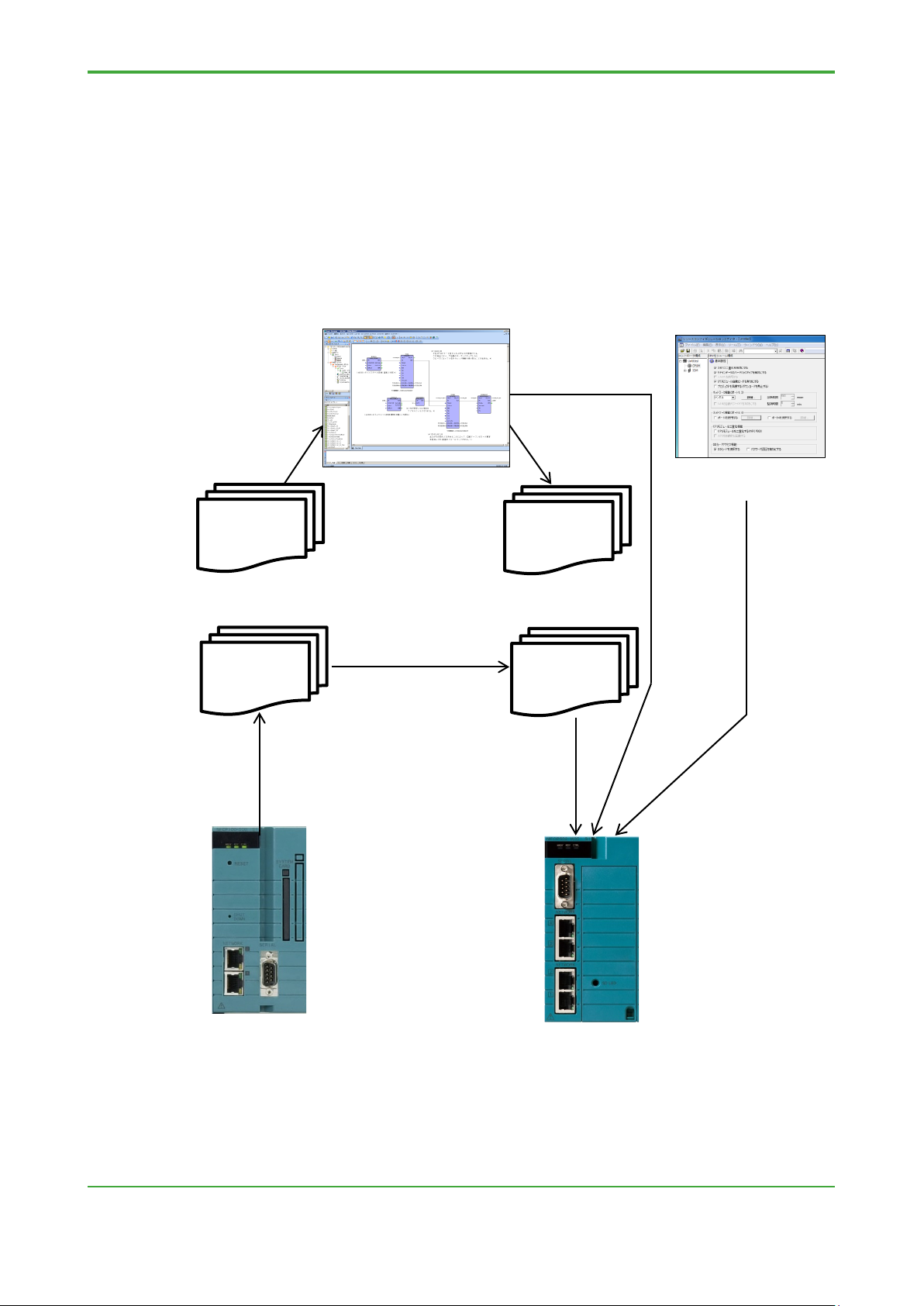
1. Overview
This chapter describes the migration procedure from the data and control
applications on the NFCP100, to the NFCP501/NFCP502.
First step, backing up, convert and restore the data on the controller by the command
operation on the personal computer.
Next step, migrate the control application for the NFCP100 (project on the Logic
Designer), to for the NFCP501/NFCP502. And download to the NFCP501/NFCP502.
control
Configurator
R3
Project
NFCP100
Files
(FcxBackup)
(FcxConvert)
R4
Project
NFCP500
Files
(FcxRestore)
TI 34P02K71-01E 4th Edition: Jun. 6, 2018-00
NFCP100
NFCP502
Figure Overview of migration
Page 6

< 1. Overview >
2
1.1 Backing up, Converting, Restoring Data
This section describes the command for backing up the data of the NFCP100,
for converting it for the NFCP501/NFCP502, and for restoring it to the
NFCP501/NFCP502.
The converted file is shown below.
- Retain saved file
- Settings of the resource configurator
- DUONUS.PRP
Setting items that are not included in the NFCP100, will be the default value. If
necessary, set it.
- CPU duplex configuration
- SNTP server
- Ethernet port No.3 and No.4 for NFCP502
- SD card
TIP
- Control application, boot project and the source file is not a conversion target. These are compiled
and downloaded by the Logic Designer.
- FcxConvert command can not convert the file that was backed up from NFJT100. Re-set IO
setting by the resource configurator. Re-set
saved file can be restored without conversion.
DUONUS.PRP by the maintenance page. Retain
● FcxBackup Command
This command backs up the target files from NFCP100 or NFJT100.
"BACKUP" folder will be created in the current directory.
Command: FcxBackup -all -u <User name> -p <Password>
<Host name or IP address>}
User name: User name of the administrator account.
Password: Password of the administrator account.
Host name or IP address:
Host name or IP address of the NFCP100.
E.g.: FcxBackup –all -u user01 -p abc123 192.168.0.1
TIP
- When you run the FcxBackup, FcxConvert and FcxRestore command in the command prompt,
move to the unzipped folder.
- The "-all" argument can be used FcxBackup command R3.10 or later.
- The "-u <user name>" and "-p <password>" argument can be used FcxBackup command R4.10 or
later. If you have changed the user name and password from the initial value, be sure to specify
them always.
TI 34P02K71-01E 4th Edition: Jun. 6, 2018-00
Page 7

< 1. Overview >
3
● FcxConvert Command
This command converts the FcxBackup command output file to NFCP501/NFCP502 file.
Command: FcxConvert.exe -t {new CPU type} -i {Source folder} -o {Destination
folder}
New CPU type: “NFCP501” or “NFCP502”
Source folder: “BACKUP”
Destination folder:
E.g. “BACKUP_NFCP501”
Please rename “BACKUP_NFCP501” into “BACKUP” when it is restored
to NFCP501/NFCP502.
E.g.: FcxConvert.exe -t NFCP501 -i BACKUP -o BACKUP_NFCP501
● FcxRestore Command
This command restores (downloads) the FcxConvert command output file to NFCP501/
NFCP502.
Command: FcxRestore {Host name or IP address}
Host name or IP address:
Host name or IP address of the NFCP501/NFCP502.
E.g.: FcxRestore 192.168.0.1
TIP
When restoring the file backed up from the NFCP100 and converted, to the NFCP501 /NFCP502, the
IP address of the backup source is set as the restore destination.
● FcxSaveRetain Command
This command saves, acquires, restores, and clears the retained data.
In this TI, only clear option is used. The command with "-c" option clears the retain data
on the SRAM. This command is used together with the FcxRestore command to ensure
that the backed up retained data is reflected in the SRAM.
Command: FcxSaveRetain -c {Host name or IP address}
Host name or IP address:
Host name or IP address of the NFCP501/NFCP502.
E.g.: FcxSaveRetain -c 192.168.0.1
TI 34P02K71-01E 4th Edition: Jun. 6, 2018-00
Page 8

< 1. Overview >
4
● Folder configuration example
If you specify "C:\temp" to the destination folder of the conversion tool
C:
temp
NFCP500 : Current Folder
FcxBackup.exe : Backup command
FcxConvert.exe : Convert command
FcxRestore.exe : Restore command
BACKUP : Backup folder
BACKUP_NFCP501 : Destination folder
TI 34P02K71-01E 4th Edition: Jun. 6, 2018-00
Page 9

< 1. Overview >
5
Processer
type
Migration Procedure
IPC_40
FCX
Re-compile
Create resource for IPC_40,
If expand the retain data
(refer to IMPORTANT)
IPC_32
IPC_33
Create resource for IPC_40,
and re-compile
SH_40
Create resource for IPC_40,
and re-compile
IMPORTANT
1.2 Migrating the Control Application
This section describes procedure of migrate the control applications (project
on the Logic Designer) for NFCP100 and NFJT100 to NFCP501/NFCP502.
In Section 2 or later describes the procedure of the case you do not extend
retain data area fundamentally.
● Not expanding the retain data area (Migration)
- If the PLC type is IPC_40, this control application (project) can be used by re-compiling
without changing itself.
- If the PLC type is IPC_32 or IPC_33, re-create the resource with IPC_40, and re-
compile.
● Expanding the retain data area (Extend function)
- If the PLC type is IPC_40, re-create the resource with “FCFX_B”/ “FCFX_C”, and
re-compile.
- If the PLC type is “IPC_32” or “IPC_33”, re-create the resource with “IPC_40” and
“FCFX_B”, and re-compile.
PLC type
Remark
FCX_A
If retain data area is extended, it is careful in clearing retained data.
FCX_B/FCX_C, and re-compile
area
TI 34P02K71-01E 4th Edition: Jun. 6, 2018-00
Page 10

< 1. Overview >
6
Processer
type
Controller
IPC_33
FCX
NFCP100 (*2)
R1.01 or later (FCX_A: R1.11 or later)
IPC_33
R1.30 or later
IPC_40
R1.50 or later
IPC_40
FCX_B
NFCP501/NFCP502
FCN/FCJ simulator
R4.02 or later
IPC_40
FCX_C
NFCP501/NFCP502
FCN/FCJ simulator
R4.20 or later
TIP
The combination of PLC type and processor type is shown in the table below.
PLC type
Remark
FCX_A
NFJT100 (FCJ)
FCN/FCJ simulator
*1: FCX: For NFJT100 or NFCP100 (not use NFLF111/NFGS813/NFGP813
/NFLP121/NFLC121)
FCX_A: For NFCP100 (use NFLF111/NFGS813/NFGP813/NFLP121
/NFLC121)
FCX_B: For NFCP501/NFCP502, retain data area extended version of FCX_A
FCX_C: For NFCP501/NFCP502 with three or more extension units and
NFLF111/NFLP121/NFLC121, device label extended version of FCX_B
*2: If the PLC type is IPC_40, the project for NFCP100 can be used by re-compiling
without changing itself.
If the PLC type is IPC_32 / IPC_33, re-create the resource with IPC_40.
If you want to change the processor type to FCX_B/FCX_C, re-create the
resource with IPC_40.
● Using the RS-232-C port on the FCJ
Change the port name used in the application program.
COM1: If you are migrating to COM1 of NFCP501/NFCP502, the application program
about the communication of the COM1 port is not changed.
If you are migrating to a port of the RS-232C communication module, change in
the same manner as the COM2 in the next section.
COM2: Migrate to a port of the RS-232C communication module.
Set the Port name of RS-232C communication module (e.g.) RS02 in the
resource configurator.
Change “COM2” to (e.g.) “RS02” in the application program.
TI 34P02K71-01E 4th Edition: Jun. 6, 2018-00
Page 11

< 2. Migration on the target device directly>
7
2. Migrating on the target device directly
This chapter describes the steps to migrate on the target device directly.
This text describes the steps to migrate from NFCP100 to NFCP500. Except for
the noted items, it is also true for NFJT100.
Migration Environment
The Tools for NFCP500 are required on the engineering PC.
- Logic Designer R4.20 or later
- Resource Configurator R4.20 or later
- Backup, Convert and Restore commands R4.20 or later
TIP
To back up NFCP 100, a Windows 7 or Windows 10 engineering PC is required. Backup commands
(R4.20 or later) will not work on Windows XP or Windows Vista PCs.
TI 34P02K71-01E 4th Edition: Jun. 6, 2018-00
Page 12
< 2. Migration on the target device directly>
8
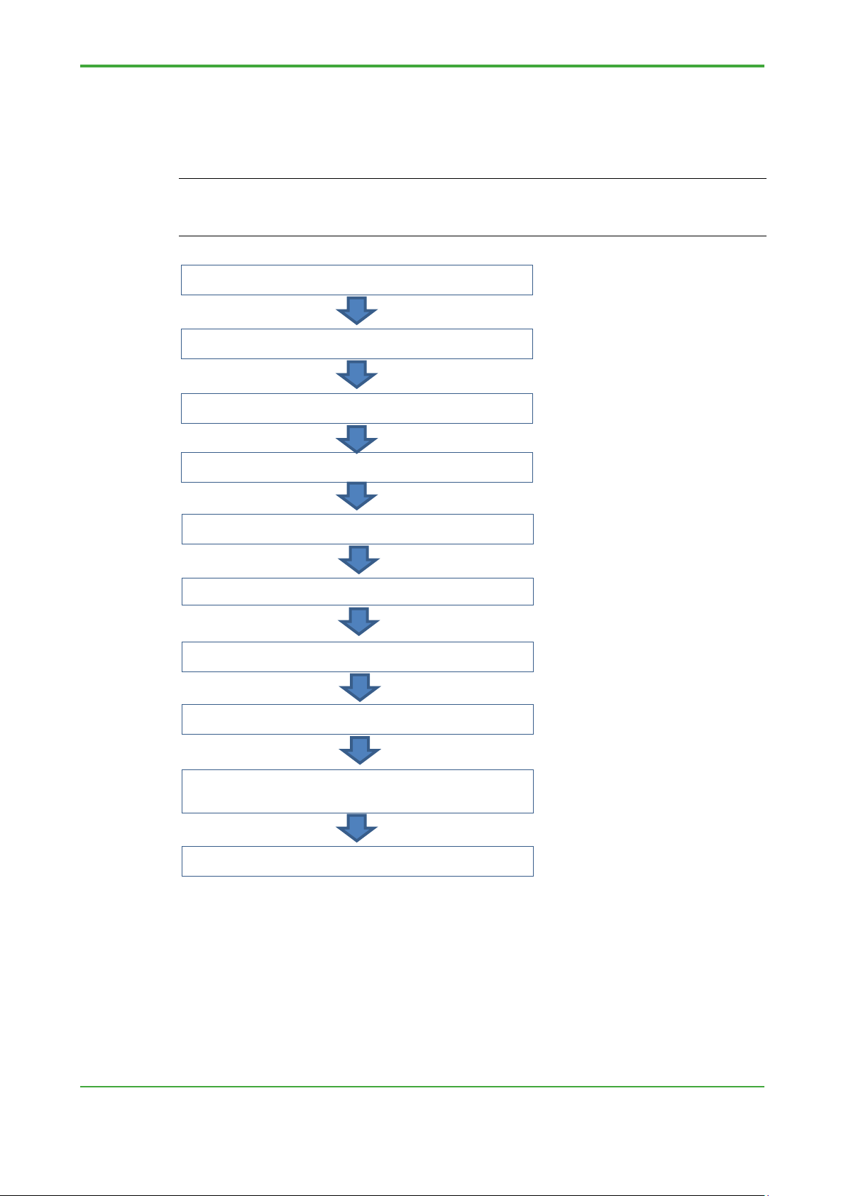
to the NFCP500
Step A6: Switching to maintenance mode
Migration Procedure (on the target device directly)
The following flowchart shows the overview of migration work on the target device
directly.
TIP
The definition information of the fieldbus (NFLF111, NFLP121, NFLC121) is stored on the engineering
PC with the IP address of the controller as the key. If field bus communication modules are used, it
requires advance preparation. For detail, refer to Appendix 3 "Field bus Definition".
Step A1: Obtaining conversion tools
Step A2: Saving the retain data on the NFCP100
Step A3: Backing up the NFCP100
Step A4: Converting the backup files
Step A5: Exchanging the CPU module
Step A7: Restoring the NFCP500
Step A8: Setting each function for NFCP500
Step A9: Downloading the control application
Step A10: Executing APC (Duplex CPU only)
Figure Flowchart of migration
TI 34P02K71-01E 4th Edition: Jun. 6, 2018-00
Page 13

< 2. Migration on the target device directly>
9
Procedure
● Step A1: Obtaining conversion tools
(1) Insert the system DVD-ROM for the R4.20 or later in the DVD drive.
(2) Select “DVD Contents.”
(3) Double-click the FCN/FCJ Basic Software Package.
- Pkg_NFCP500.exe in the Pkg_NFCP500 folder for FCN-500
(4) Specify a folder for saving unzipped files, and click the [Install] button.
The conversion tools are unzipped.
TIP
For example, if the specified folder for storing unzipped files is “C:\temp,” the following files will be
created in that Folder.
C:\temp\NFCP500\FcxBackup.exe
C:\temp\NFCP500\FcxRestore.exe
C:\temp\NFCP500\FcxConvert.exe
C:\temp\FCXTOOL\FcxSaveRetain.bat
C:\temp\FCXTOOL\save_retain.txt
To specify the name for the unzipped folder, do not include space in the name of the folder.
● Step A2: Saving the retain data on the NFCP100
(1) Run the Web browser and open the “STARDOM Maintenance Page” on the
NFCP100.
(2) Click “Maintenance Menu.”
The FCX Maintenance Menu is displayed.
(3) Click “Save Retain Data.”
The last time and data when the retain data was saved is displayed.
(4) Click the [SAVE] button.
The retain data is saved.
Figure Saving the retain data
TI 34P02K71-01E 4th Edition: Jun. 6, 2018-00
Page 14

< 2. Migration on the target device directly>
10
TIP
The [SAVE] button is not displayed in the maintenance mode.
If prior to R1.70, please save the retain data refer to the online help.
If the retain data area to extend, the data saved in Step A2 is not available in NFCP500.
● Step A3: Backing up the NFCP100
(1) In the command prompt window, change the current directory to the folder
containing the extracted conversion tools in Step A1.
Supposing that the conversion tools have been extracted to the folder C:¥temp,
type “cd C:\temp\NFCP500” and press the [Enter] key.
(2) In the command prompt window, type “FcxBackup -all -u <user name> -p
<password> <host name or IP address>,” and press the [Enter] key.
"BACKUP" folder will be created in the current directory.
e.g. C:\temp\NFCP500> FcxBackup -all -u user01 -p abc123
192.168.0.1
TIP
If already have a backup, you can skip this step.
● Step A4: Converting the backup files (except NFJT100)
(1) In the command prompt window, type “FcxConvert –t <new CPU type> -i
<Source folder> -o <Destination folder>,” and press the [Enter] key.
Some files for the NFCP501/NFCP502 are created to the destination folder.
e.g. C:\temp\NFCP500> FcxConvertp –t NFCP501 –i BACKUP
–o BACKUP_NFCP501
● Step A5: Exchanging the CPU module
(1) Remove the NFCP100 from the base module.
In the case of CPU duplex configuration, remove also the two.
(2) Transfer the Ethernet cable and the RS-233-C cable from NFCP100 to
NFCP501/NFCP502.
Attach the Ethernet cables to the same Ethernet port 1 or 2 before the
exchange.
(3) In the case of new goods NFCP501/NFCP502, start the resources configurator
to set the IP address.
(4) Insert the NFCP501/NFCP502 to the base module.
In the case of CPU duplex configuration, insert only the control side CPU
module in this step.
(5) In the case of new goods NFCP501/NFCP502, so the start-up in the IP address
setting mode, and set the IP address in the resource configurator.
After setting, you can exit the resources configurator.
TI 34P02K71-01E 4th Edition: Jun. 6, 2018-00
Page 15

< 2. Migration on the target device directly>
11
● Step A6: Switching to maintenance mode on the NFCP500
(1) Run the Web browser and open the “STARDOM Maintenance Page” on the
NFCP501/NFCP502.
(2) Select “Maintenance Menu.”
The FCX Maintenance Menu is displayed.
(3) Select “Reboot.”
The Reboot Menu is displayed.
(4) Select “Reboot (Maintenance Mode)” and click the [OK] button.
The NFCP501/NFCP502 boots up in maintenance mode.
(5) Make sure that it has been started in a maintenance mode, and exit the Web
browser.
● Step A7: Restoring to the NFCP500
(1) Rename "BACKUP" folder in Step A3 to another name.
(2) Rename the destination folder in Step A4 to "BACKUP".
(3) In the command prompt window, type “FcxSaveRetain -c <host name or IP
address>,” and press the [Enter] key.
The command with "-c" option only clears the retain data on the SRAM and
does not save the retain data.
e.g. C:\temp\NFCP500> FcxSaveRetain -c 192.168.0.1
(4) In the command prompt window, type “FcxRestore <host name or IP address>,”
and press the [Enter] key.
e.g. C:\temp\NFCP500> FcxRestore 192.168.0.1
(5) After restoring, change to the online mode in the maintenance page.
(6) Make sure that it has been started in online mode, and exit the Web browser.
TIP
The IP address of the restored NFCP501/NFCP502 is reflected the IP address of NFCP100.
If necessary, change the IP address. If field bus (NFLF111, NFLP121, NFLC121) are used, do the
following after Step A7 restore. Step A7-1: Exported by Resource Configurator, Step A7-2: Change IP
address, and Step A7-3: Imported by resource configurator.
License information can’t be migrated to the FCN-500. Please use the CPU module to the required
licenses are bundled.
TI 34P02K71-01E 4th Edition: Jun. 6, 2018-00
Page 16

< 2. Migration on the target device directly>
12
● Step A8: Setting each function for the NFCP500
(1) Set some settings for new function or additional configuration by the resource
configurator, and download it.
- Duolet function (If necessary)
- CPU
- Ethernet port No.3 and No.4 for NFCP502 (
- SD card: (
- I/O definition (migrating from NFJT100 only)
duplex configuration (If necessary)
If necessary)
If necessary)
(2) Set some settings for new function or additional configuration by the resource
configurator,.
- SNTP server (If necessary)
SEE ALSO
For setting of the SNTP server, refer to the "2.2.6 Time Synchronization" TI "STARDOM Engineering
Guide (FCN-500/FCN-RTU)".
TI 34P02K71-01E 4th Edition: Jun. 6, 2018-00
Page 17

< 2. Migration on the target device directly>
13
● Step A9: Downloading the control application to the NFCP500
(1) If you have the user library project, copy the user library (mwt file) and the folder
named the same name as the library project into the library folder.
E.g.: Copy Userlib.mwt and Userlib folder into
“C:\YOKOGAWA\FCN-FCJ\LogicDesigner\Libraries”
If the user library is compressed in this project, it is also copied user library
when it is decompressed. If an existing project is present, it compares the
version information before overwriting, and select to overwrite or Save As.
Compile the project of the user library in the logic designer of R4 after thawing.
TIP
The user library is a project to which the user is to create your own reference. Library of APPF is not
included.
If you are not using the user library, this step is not necessary.
(2) Open the project (R1/R2/R3/R4) by the Logic Designer R4.
The projects in the format of R3 or earlier are converted automatically to R4
format.
TIP
The project of R4 format can’t be opened in the R1/R2/R3 Logic Designer.
(3) If the PLC type is defined in IPC_32 / IPC_33, re-create the resource (PLC type:
IPC_40). When you re-create the resource, copy and set the definition following
information on the logic designer.
- Copy of the task definition
- Copy of the Program POU instance definition
- Copy of the global variable definition
- Setting of target setting dialog
- Copy of the device label variable definition
- Copy of the software wiring definition
- Change of resource names
SEE ALSO
Detailed procedure of re-creating resources, refer to online help "Control Application Programming
Guide" - "Control application creating" - "Considerations in the control application programming" "Project data management."
TIP
If the retain data area to extend, re-create the resource (PLC type: IPC_40, Processer type: FCX_B
/FCX_C).
If the retain data area to extend, the data saved is not available in NFCP500.
If changing the processor type of existing resources, the retain data area will not be extended.
TI 34P02K71-01E 4th Edition: Jun. 6, 2018-00
Page 18

< 2. Migration on the target device directly>
14
(4) Make the project by the Logic Designer R4.
(5) Perform offline download the control application to the NFCP501/NFCP502.
Also download the boot project and the source files as needed.
● Step A10: Executing APC (Duplex CPU only)
(1) After confirming the connection of Ethernet cable and the RS-233-C cable,
insert the other one CPU module for stand-by side.
(2) Run the APC. If APC automatic startup is disabled, run the APC from the
resource configurator.
TIP
In the control side and standby side CPU module, use the same model and same revision of basic
software.
TI 34P02K71-01E 4th Edition: Jun. 6, 2018-00
Page 19

< 3. Migration in-house equipment in advance>
15
3. Migrating in-house equipment in advance
This chapter describes the following procedure.
Bring back the data that was backed up from the target equipment on site.
Check the operation and conversion work in-house equipment. And then,
work for the target equipment on site.
(1) In Step B1 to B16 describes the following procedure.
Without providing the same I/O configuration as the target device as an inhouse equipment, check the operation with a minimum configuration of
NFCP500, power supply and base module.
Then, reflect the results operation check in-house to NFCP500 in the field.
(2) In Step B1 to B10 and C11 to C14 describes the following procedure.
Prepare the same I/O configuration as the target device as an in-house
equipment, check the operation in-house.
Then, replace the NFCP500 used in the operation check in-house in the
field.
This text describes the steps to migrate from NFCP100 to NFCP500. Except for
the noted items, it is also true for NFJT100.
Migration Environment
The Tools for NFCP500 are required on the engineering PC of both the site and the inhouse.
- Logic Designer R4.20 or later
- Resource Configurator R4.20 or later
- Backup, Convert and Restore commands R4.20 or later
TIP
To back up NFCP 100, a Windows 7 or Windows 10 engineering PC is required. Backup commands
(R4.20 or later) will not work on Windows XP or Windows Vista PCs.
TI 34P02K71-01E 4th Edition: Jun. 6, 2018-00
Page 20

< 3. Migration in-house equipment in advance>
16
Step B9: Downloading the control application
to the NFCP500
Step B6: Switching to maintenance mode
Same as target
On site
In-house
Migration Procedure (In advance to work in-house equipment)
The following flowchart shows the overview of migration work in advance to work inhouse equipment.
TIP
The definition information of the fieldbus (NFLF111, NFLP121, NFLC121) is stored on the engineering
PC with the IP address of the controller as the key. If field bus communication modules are used, it
requires advance preparation. For detail, refer to Appendix 3 "Field bus Definition".
Step B1: Obtaining conversion tools
Step B2: Saving the retain data on the NFCP100
Step B3: Backing up the NFCP100
Step B4: Converting the backup files
Step B5: Setting the IP address
Step B7: Restoring the NFCP500
Step B8: Setting each function for NFCP500
I/O definition
CPU only
C11
TI 34P02K71-01E 4th Edition: Jun. 6, 2018-00
B11
Page 21

< 3. Migration in-house equipment in advance>
17
Step B15: Downloading the control application
to the NFCP500
On site
Step C12: Backing up the NFCP500
Step C13: Exchanging the CPU module
Step C14: Executing APC (Duplex CPU only)
On site
In-house
B11
Step B11: Exchanging the CPU module
Step B12: Switching to maintenance mode
Step B13: Restoring the NFCP500
Step B14: Setting each function for NFCP500
Step B16: Executing APC (Duplex CPU only)
Step C11: Saving the retain data on the NFCP500
Figure Flowchart of migration
C11
TI 34P02K71-01E 4th Edition: Jun. 6, 2018-00
Page 22

< 3. Migration in-house equipment in advance>
18
Procedure (Work of target equipment in advance)
● Step B1: Obtaining conversion tools
(1) Insert the system DVD-ROM for the R4.20 or later in the DVD drive.
(2) Select “DVD Contents.”
(3) Double-click the FCN/FCJ Basic Software Package.
- Pkg_NFCP500.exe in the Pkg_NFCP500 folder for FCN-500.
(4) Specify a folder for saving unzipped files, and click the [Install] button.
The conversion tools are unzipped.
TIP
For example, if the specified folder for storing unzipped files is “C:\temp,” the following files will be
created in that folder.
C:\temp\NFCP500\FcxBackup.exe
C:\temp\NFCP500\FcxRestore.exe
C:\temp\NFCP500\FcxConvert.exe
C:\temp\FCXTOOL\FcxSaveRetain.bat
C:\temp\FCXTOOL\save_retain.txt
To specify the name for the unzipped folder, do not include space in the name of the folder.
● Step B2: Saving the retain data on the NFCP100
(1) Run the Web browser and open the “STARDOM Maintenance Page” on the
NFCP100.
(2) Click “Maintenance Menu.”
The FCX Maintenance Menu is displayed.
(3) Click “Save Retain Data.”
The last time and data when the retain data was saved is displayed.
(4) Click the [SAVE] button.
The retain data is saved.
Figure Saving the retain data
TI 34P02K71-01E 4th Edition: Jun. 6, 2018-00
Page 23

< 3. Migration in-house equipment in advance>
19
TIP
The [SAVE] button is not displayed in the maintenance mode.
If prior to R1.70, please save the retain data refer to the online help.
If the retain data area to extend , the data saved in Step A2 is not available in NFCP500.
● Step B3: Backing up the NFCP100
(1) In the command prompt window, change the current directory to the folder
containing the extracted conversion tools in Step B1.
Supposing that the conversion tools has been extracted to the folder C:¥temp,
type “cd C:\temp\NFCP500” and press the [Enter] key.
(2) In the command prompt window, type “FcxBackup -all -u <user name> -p
<password> <host name or IP address>,” and press the [Enter] key.
"BACKUP" folder will be created in the current directory.
e.g. C:\temp\NFCP500> FcxBackup -all -u user01 -p abc123
192.168.0.1
TIP
If already have a backup, you can skip this step.
TI 34P02K71-01E 4th Edition: Jun. 6, 2018-00
Page 24

< 3. Migration in-house equipment in advance>
20
Procedure (Work of in-house equipment)
● Step B4: Converting the backup files (except NFJT100)
(1) In the command prompt window, move to the unzipped folder in step B1.
(2) In the command prompt window, type “FcxConvert –t <new CPU type> -i
<Source folder> -o <Destination folder>,” and press the [Enter] key.
Some files for the NFCP501/NFCP502 are created to the destination folder.
e.g. C:\temp\NFCP500> FcxConvert –t NFCP501 –i BACKUP
–o BACKUP_NFCP501
● Step B5: Exchanging the CPU module
(1) In the case of new goods NFCP501/NFCP502, start the resources configurator
to set the IP address.
(2) Start the NFCP501/NFCP502.
(3) In the case of new goods NFCP501/NFCP502, so the start-up in the IP address
setting mode, and set the IP address in the resource configurator.
After setting, you can exit the resources configurator.
● Step B6: Switching to maintenance mode on the NFCP500
(1) Run the Web browser and open the “STARDOM Maintenance Page” on the
NFCP501/NFCP502.
(2) Select “Maintenance Menu.”
The FCX Maintenance Menu is displayed.
(3) Select “Reboot.”
The Reboot Menu is displayed.
(4) Select “Reboot (Maintenance Mode)” and click the [OK] button.
The NFCP501/NFCP502 boots up in maintenance mode.
(5) Make sure that it has been started in a maintenance mode, and exit the Web
browser.
● Step B7: Restoring to the NFCP500
(1) Rename "BACKUP" folder in Step B3 to another name.
(2) Rename the destination folder in Step B4 to "BACKUP".
(3) In the command prompt window, type “FcxSaveRetain -c <host name or IP
address>,” and press the [Enter] key.
The command with "-c" option only clears the retain data on the SRAM and
does not save the retain data.
e.g. C:\temp\NFCP500> FcxSaveRetain -c 192.168.0.1
(4) In the command prompt window, type “FcxRestore <host name or IP address>,”
and press the [Enter] key.
e.g. C:\temp\NFCP500> FcxRestore 192.168.0.1
(5) After restoring, change to the online mode in the maintenance page.
(6) Make sure that it has been started in online mode, and exit the Web browser.
TI 34P02K71-01E 4th Edition: Jun. 6, 2018-00
Page 25

< 3. Migration in-house equipment in advance>
21
TIP
The IP address of the restored NFCP501/NFCP502 is reflected the IP address of NFCP100.
If necessary, change the IP address. If field bus (NFLF111, NFLP121, NFLC121) are used, do the
following after Step B7 restore. Step B7-1: Exported by Resource Configurator, Step B7-2: Change IP
address, and Step B7-3: Imported by resource configurator.
License information can’t be migrated to the FCN-500. Please use the CPU module to the required
licenses are bundled.
● Step B8: Setting each function for the NFCP500
(1) Set some settings for new function or additional configuration by the resource
configurator, and download it.
- Duolet function (If necessary)
- CPU duplex configuration (
- Ethernet port No.3 and No.4 for NFCP502 (
- SD card (
If necessary)
- I/O definition (migrating from NFJT100 only)
If necessary)
If necessary)
(2) Set some settings for new function or additional configuration by the resource
configurator,.
- SNTP server (If necessary)
SEE ALSO
For setting of the SNTP server, refer to the "2.2.6 Time Synchronization" TI "STARDOM Engineering
Guide (FCN-500/FCN-RTU)".
TI 34P02K71-01E 4th Edition: Jun. 6, 2018-00
Page 26

< 3. Migration in-house equipment in advance>
22
● Step B9: Downloading the control application to the NFCP500
(1) If you have the user library project, copy the user library (mwt file) and the folder
named the same name as the library project into the library folder.
E.g.: Copy Userlib.mwt and Userlib folder into
“C:\YOKOGAWA\FCN-FCJ\LogicDesigner\Libraries”
If the user library is compressed in this project, it is also copied user library
when it is decompressed. If an existing project is present, it compares the
version information before overwriting, and select to overwrite or Save As.
Compile the project of the user library in the logic designer of R4 after thawing.
TIP
The user library is a project to which the user is to create your own reference. Library of APPF is not
included.
If you are not using the user library, this step is not necessary.
(2) Open the project (R1/R2/R3/R4) by the Logic Designer R4.
The projects in the format of R3 or earlier are converted automatically to R4
format.
TIP
The project of R4 format can’t be opened in the R1/R2/R3 Logic Designer.
(3) If the PLC type is defined in IPC_32 / IPC_33, re-create the resource (PLC type:
IPC_40). When you re-create the resource, copy and set the definition following
information on the logic designer.
- Copy of the task definition
- Copy of the Program POU instance definition
- Copy of the global variable definition
- Setting of target setting dialog
- Copy of the device label variable definition
- Copy of the software wiring definition
- Change of resource names
SEE ALSO
Detailed procedure of re-creating resources, refer to online help "Control Application Programming
Guide" - "Control application creating" - "Considerations in the control application programming" "Project data management."
TIP
If the retain data area to extend, re-create the resource (PLC type: IPC_40, Processer type: FCX_B
/FCX_C).
If the retain data area to extend, the data saved is not available in NFCP500.
If changing the processor type of existing resources, the retain data area will not be extended.
(4) Make the project by the Logic Designer R4.
TI 34P02K71-01E 4th Edition: Jun. 6, 2018-00
Page 27

< 3. Migration in-house equipment in advance>
23
(5) Perform offline download the control application to the NFCP501/NFCP502.
Also download the boot project and the source files as needed.
● Step B10: Checking the operation of NFCP500
- Hardware operation (communication function, CPU duplex configuration)
- The operation of the control application
TIP
If the in-house facilities site CPU type and the I/O module configuration is different, here the backup of
the data is not available in the work in the field..
TI 34P02K71-01E 4th Edition: Jun. 6, 2018-00
Page 28

< 3. Migration in-house equipment in advance>
24
Procedure (Work of target equipment)
● Step B11: Exchanging the CPU module
(1) Remove the NFCP100 from the base module.
In the case of CPU duplex configuration, remove also the two.
(2) Transfer the Ethernet cable and the RS-233-C cable from NFCP100 to
NFCP501/NFCP502.
Attach the Ethernet cables to the same Ethernet port 1 or 2 before the
exchange.
(3) In the case of new goods NFCP501/NFCP502, start the resources configurator
to set the IP address.
(4) Insert the NFCP501/NFCP502 to the base module.
In the case of CPU duplex configuration, insert only the control side CPU
module in this step.
(5) In the case of new goods NFCP501/NFCP502, so the start-up in the IP address
setting mode, and set the IP address in the resource configurator.
After setting, you can exit the resources configurator.
● Step B12: Switching to maintenance mode on the NFCP500
(1) Run the Web browser and open the “STARDOM Maintenance Page” on the
NFCP501/NFCP502.
(2) Select “Maintenance Menu.”
The FCX Maintenance Menu is displayed.
(3) Select “Reboot.”
The Reboot Menu is displayed.
(4) Select “Reboot (Maintenance Mode)” and click the [OK] button.
The NFCP501/NFCP502 boots up in maintenance mode.
(5) Make sure that it has been started in a maintenance mode, and exit the Web
browser.
● Step B13: Restoring to the NFCP500
(1) Rename "BACKUP" folder in Step B3 to another name.
(2) Rename the destination folder in Step B4 to "BACKUP".
(3) In the command prompt window, type “FcxSaveRetain -c <host name or IP
address>,” and press the [Enter] key.
The command with "-c" option only clears the retain data on the SRAM and
does not save the retain data.
e.g. C:\temp\NFCP500> FcxSaveRetain -c 192.168.0.1
(4) In the command prompt window, move to the unzipped folder in step B1.
(5) In the command prompt window, type “FcxRestore <host name or IP address>,”
and press the [Enter] key.
e.g. C:\temp\NFCP500> FcxRestore 192.168.0.1
TI 34P02K71-01E 4th Edition: Jun. 6, 2018-00
Page 29

< 3. Migration in-house equipment in advance>
25
TIP
The IP address of the restored NFCP501/NFCP502 is reflected the IP address of NFCP100.
If necessary, change the IP address. If field bus (NFLF111, NFLP121, NFLC121) are used, do the
following after Step B7 restore. Step B13-1: Exported by Resource Configurator, Step B13-2: Change
IP address, and Step B13-3: Imported by resource configurator.
License information can’t be migrated to the FCN-500. Please use the CPU module to the required
licenses are bundled.
● Step B14: Setting each function for the NFCP500
(1) Set some settings for new function or additional configuration by the resource
configurator, and download it.
- Duolet function (If necessary)
- CPU duplex configuration (
- Ethernet port No.3 and No.4 for NFCP502 (
- SD card (
If necessary)
- I/O definition (migrating from NFJT100 only)
If necessary)
If necessary)
(2) Set some settings for new function or additional configuration by the resource
configurator,.
- SNTP server (If necessary)
SEE ALSO
For setting of the SNTP server, refer to the "2.2.6 Time Synchronization" TI "STARDOM Engineering
Guide (FCN-500/FCN-RTU)".
TI 34P02K71-01E 4th Edition: Jun. 6, 2018-00
Page 30

< 3. Migration in-house equipment in advance>
26
IMPORTANT
● Step B15: Downloading the control application to the NFCP500
(1) Open the project in step B9 by the Logic Designer R4.
(2) Perform offline download the control application to the NFCP501/NFCP502.
Also download the boot project and the source files as needed.
The retain data that changed or added to in-house equipment, re-set it in the field.
● Step B16: Executing APC (Duplex CPU only)
(1) After confirming the connection of Ethernet cable and the RS-233-C cable,
insert the other one CPU module for stand-by side.
(2) Run the APC. If APC automatic startup is disabled, run the APC from the
resource configurator.
TIP
In the control side and standby side CPU module, use the same model and same revision of basic
software.
TI 34P02K71-01E 4th Edition: Jun. 6, 2018-00
Page 31

< 3. Migration in-house equipment in advance>
27
Procedure (Work of in-house equipment)
● Step C11: Saving the retain data on the NFCP500
(1) Run the Web browser and open the “STARDOM Maintenance Page” on the
NFCP501/NFCP502.
(2) Click “Maintenance Menu.”
The FCX Maintenance Menu is displayed.
(3) Click “Save Retain Data.”
The last time and data when the retain data was saved is displayed.
(4) Click the [SAVE] button.
The retain data is saved.
Figure Saving the retain data
TIP
The [SAVE] button is not displayed in the maintenance mode.
● Step C12: Backing up the NFCP500
(1) In the command prompt window, change the current directory to the folder
containing the extracted conversion tools in Step B1.
Supposing that the conversion tools has been extracted to the folder C:¥temp,
type “cd C:¥temp¥NFCP500” and press the [Enter] key.
(2) In the command prompt window, type “FcxBackup -all -u <user name> -p
<password> <host name or IP address>,” and press the [Enter] key.
"BACKUP" folder will be created in the current directory.
e.g. C:\temp\NFCP500> FcxBackup -all -u user01 -p abc123
192.168.0.1
TIP
This backup is the storage of the contents of the in-house work. You do not need to restore the content
in the field.
TI 34P02K71-01E 4th Edition: Jun. 6, 2018-00
Page 32

< 3. Migration in-house equipment in advance>
28
Procedure (Work of target equipment)
● Step C13: Exchanging the CPU module
(1) Remove the NFCP100 from the base module.
In the case of CPU duplex configuration, remove also the two.
(2) Transfer the Ethernet cable and the RS-233-C cable from NFCP100 to
NFCP501/NFCP502.
Attach the Ethernet cables to the same Ethernet port 1 or 2 before the
exchange.
(3) Insert the NFCP501/NFCP502 using in-house equipment to the base module.
In the case of CPU duplex configuration, insert only the control side CPU
module in this step.
● Step C14: Executing APC (Duplex CPU only)
(1) After confirming the connection of Ethernet cable and the RS-233-C cable,
insert the other one CPU module for stand-by side.
(2) Run the APC. If APC automatic startup is disabled, run the APC from the
resource configurator.
TIP
In the control side and standby side CPU module, use the same model and same revision of basic
software.
TI 34P02K71-01E 4th Edition: Jun. 6, 2018-00
Page 33

< Appendix 1 FCN/FCJ and development tools >
29
R4 Logic Designer
R4 Resource Configurator
FCN/FCJ Basic software
R1 - R2 - R3 X R4
X
Appendix 1 FCN/FCJ and development
tools
This appendix describes combination of the FCN/FCJ and the development
tools.
● Combination of the FCN/FCJ and the development tools
Logic designer R4 and Resource Configurator R4 can develop FCN/FCJ autonomous
controller with basic software R3 and R4.
FCN/FCJ Autonomous controller
- When opened in logic designer R4, a project that was created in a previous edition
Logic Designer (R1/R2/R3), are automatically converted to R4 format.
- A project that was saved in the Logic Designer R4, can’t be opened in previous edition
Logic Designer.
- Match the release and the revision of Logic Designer, Resource Configurator and
FCN/FCJ basic software.
TI 34P02K71-01E 3rd Edition: Aug. 28, 2017-00
Page 34

< Appendix 2 Sample Libraries >
30
Application PF
Library name
SAMA PF
SD_SAMA_PF
SA_SAMA_PF
General PF
SD_GENERAL_PF
SA_GENERAL_PF
Power Monitor
Communication PF
SD_CPMPOU_PF
SA_CPMPOU_PF
Temperature Controller
Communication PF
SD_DICPOM_PF
SA_DICPOM_PF
Boiler Control PF
SD_ABOILER_PF
SA_ABOILER_PF
Boiler Auxiliary Control PF
SD_ABOILERU_PF
SA_ABOILERU_PF
Appendix 2 Sample Libraries
This appendix describes procedure that uses a POU of the following
application portfolio on autonomous controller FCN-500.
FCN-500 is not bundled with License of these APPF. To use these, you must
replace the APPF library to the sample library. There is no need to replace the
POU.
- SAMA PF
- General PF
- Power Monitor Communication PF
- Temperature Controller
- Communication PF
- Boiler Control PF
- Boiler Auxiliary Control PF
● Step 1: Obtaining Sample Libraries
Download the sample libraries from the Web site to the library folder.
URL: https://partner.yokogawa.com/global/member/rtu/engsample/index.htm
E.g.(libraly folder): “C:\YOKOGAWA\FCN-FCJ\LogicDesigner\Libraries”
● Step 2: Adding Sample Libraries
(1) Open the library compressed project file in the Logic Designer and compile it.
(2) Register the sample libraries to library of product tree in the Logic designer.
If the above application portfolio library is registered, please remove it.
Application PF
Sample Library Name
● Step 3: Compiling and Downloading
(1) Re-compile the project in the Logic designer.
(2) Perform offline download the control application.
TI 34P02K71-01E 3rd Edition: Aug. 28, 2017-00
Page 35

< Appendix 3 Field bus Definition>
31
TI 34P02K71-01E
3rd Edition: Aug. 28, 2017-00
Appendix 3 Field bus Definition
This chapter describes the work in the case of an autonomous controller
NFCP100 were using the field bus (NFLF111, NFLP121, NFLC121
communication module).
The field bus definition information must be transferred from the engineering
PC for NFCP100 to the engineering PC for NFCP500.
TIP
If you have used the R2.20 previous FF engineering tool, conversion is required from the FF engine
tool to FF configurator. It offers a tool to support this conversion. After the conversion, you must check
the operation of the field bus.
For details, refer to "STARDOM FOUNDATION fieldbus System Migration Guide", TI 34P02Q55-01E.
The field bus definition information CF/DD files for FOUNDATION fieldbus, GSD files for
PROFIBUS or EDS files for CANopen, must be copied and imported from the
engineering PC for NFCP100 to the engineering PC for NFCP500.
SEE ALSO
- For how to copy CF/DD files for FOUNDATION fieldbus, refer to “5.8 Copying Fieldbus Associated
Files”, IM 34P02Q51-02E.
For CF/DD files, refer to “Items obtained from the device vendor” of “B1.2 Preparation for
Engineering”, TI 34P02Q51-02E.
- For how to register GSD files for PROFIBUS, refer to “3.3.3 Registering GSD Files”, IM
34P02Q57-01E.
- For how to register EDS files for CANopen, refer to “3.3.1 Registering Slave Devices”, IM
34P02Q58-01E.
If you want to engineering in a new PC for the NFCP500, export the definition
information by resources configurator on the original PC, and then import this definition
information by resources configurator on the new PC.
If you upgrade the PC for NFCP100 to for NFCP500, export and import it does not need,
because the definition information of the field bus is in the PC.
● Step 1: Export of definition information
Originally a PC that had done the engineering of NFCP100, and export the resource
configurator connected to the NFCP100.
● Step 2: Import of definition information
In a new PC to perform the engineering of NFCP500, connect the resource configurator
to the NFCP100, and import the file of Step1.
● Step 3: Download of definition information
In a new PC to perform the engineering of NFCP500, connect the resource configurator
connected to the NFCP100, and download the file of Step1.
.
Page 36

< Appendix 4 Duolet Application >
32
TI 34P02K71-01E
3rd Edition: Aug. 28, 2017-00
Appendix 4 Duolet Application
This chapter describes the procedure for migrating the Java application of the
autonomous controller FCN-100/FCJ to the Duolet application of FCN-500.
Edit system configuration file DUONUS.PRP
After converting by FcxConvert, # is added before JavaStart and AdditionalClassPath in
the system setting file DUONUS.PRP. After restoring to NFCP501/NFCP502, remove
the # before the JavaStart and AdditionalClassPath in the system configuration file
DUONUS.PRP so that the application to be used is activated.
For details on editing the system configuration file, refer to "B 2.4.2 Editing System
Setting Files " in FCN/FCJ Guide, IM 34P02Q01-01E.
Migration of Duolet (Java) Application Project
To use the project created before R4.02 with FCN-500, project migration work is
required. Migrate the project according to the following procedure.
(1) Change the CallJavac.bat file in the project folder of the Duolet application to a
different name such as CallJavac.bat.old.
(2) Change the Ftp2Fcx.bat file in the project folder of the Duolet application to a
different name such as Ftp2Fcx.bat.old.
(3) Copy CallJavac.bat, CallJavac_Fcn500.bat, Ftp2Fcx.bat from the
"Project\Template" folder under the installation folder to the project folder of the
Duolet application.
(4) Set the controller's IP address, the package to be included in the JAR, and the
JAR file name in Ftp 2 Fcx.bat.
(5) Execute CallJavac.bat or CallJavac_Fcn500.bat and confirm that the Duolet
application is created.
SEE ALSO
- Deprecated methods of IEC control data access class can not be used with FCN - 500. For details,
refer to the online help of FCN/FCJ Duolet application development kit.
- For transfer of Duolet application, refer to the online help of FCN/FCJ Duolet application
development kit.
Page 37

< Revision Information >
i
Revision Information
Title: STARDOM FCN-100/FCJ Migration
Document No.: TI 34P02K71-01E
Jun. 2016/1st Edition
Newly published
May 2017/2nd Edition/R4.10 or later
Reviced
• Addition of FcxBackup command arguments.
Aug. 2017/3rd Edition/R4.10.10 or later
Reviced
• Added FcXBackup obtaining method.
• Added migration of Duolet Application.
Jun. 2018/4th Edition/R4.20 or later*
Reviced
• Added processor type FCX_C.
• Changed obtain procedure of tool.
*: Denotes the release version of the software corresponding to the contents of the technical information in
question. The revised contents are valid until the next edition is issued.
■ For Questions and More Information
If you have any questions, you can send an E-mail to the following address.
E-mail:stardom_info@cs.jp.yokogawa.com
■ Written by Yokogawa Electric Corporation
■ Published by Yokogawa Electric Corporation
2-9-32 Nakacho, Musashino-shi, Tokyo 180-8750, JAPAN
TI 34P02K71-01E 4th Edition:Jun. 6, 2018-00
 Loading...