

Page 1

User’s
Manual
IM 04L51B01-04Z1
Quick, Easy Steps
URL: www.smartdacplus.com/manual/en/
Product user’s manuals can be downloaded or viewed at the
following URL;
4th Edition : Dec. 2015
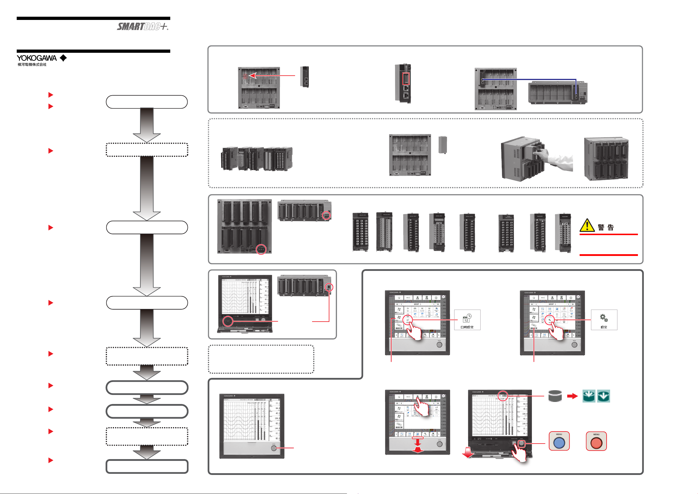
Manuals for reference
First Step Guide
Connect an GX60
(IM 04L51B01-02EN)
“
Installation and Wiring
First Step Guide
”
Install modules.
(IM 04L51B01-02EN)
“
Installation and Wiring
”
To connect an GX60.
Not required
if preinstalled
To connect an GX60,
install the modules in
the GX60.
1
Install an expansion module (GX90EX) into the GX/GP.
9
GX90EX
GX10/GP10 : Slot 2
GX20/GP20 : Slot 9
GX10/GP10: Up to 3 modules can be installed.
GX20/GP20: Up to 10 modules can be installed.
Modules (seven types)
GX90XA
Analog input
module
Connect the LAN cable bteween GX/GP and GX60.
GX60
2
1 2 3
address setting
Setting switch
(DIP switch
GX90EX
Modules not installed
Ex GX/GP
GX90XD
Digital input
module
)
Dummy covers are
attached to empty slots
(with screws).
* Recommended tightening
torque: 0.6 N•m
3
GX90YD
Digital output
module
Insert until a click is heard
and fasten with screws.*
GX90WD
Digital input/
output module
GX90XP
Pulse input
module
Modules installed
(10 modules)
First Step Guide
Connect I/O signals and power.
(IM 04L51B01-02EN)
“Installation and Wiring”
First Step Guide
(IM 04L51B01-02EN)
“
Basic Operations
First Step Guide
(IM 04L51B01-02EN)
“
Reconfiguring the
GX/GP
”
”
Make the GX/GP recognize the
modules (GX/GP reconfiguration).
First Step Guide
(IM 04L51B01-02EN)
“
Basic Operations
”
Turn on the power.
Set the date and time.
GX60
Power inlet on
Ex GX/GP
the GP10/GP20/GX60 (Power
inret type)
GX60
Power switch
If preinstalled, modules are preconfigured.
If you rearrange the modules or connect an
GX60, reconfigure.
M3 screw
terminal
Clamp
terminal
M3 screw
terminal
Clamp
terminal
Set the date and time*.
Common menu tab
Start measuring/recording.
M3 screw
terminal
M3 screw
terminal
* If you need to set the
time zone or DST (Daylight
Saving Time) or both, do
so before setting the date
and time.
To prevent electric shock when
wiring, make sure that the power
M3 screw
terminal
Clamp
terminal
supply is turned off.
Configure input and functions.
Browse tab
Recording stopped Recording in progress
First Step Guide
(IM 04L51B01-02EN)
“
Basic Operations
Paperless Recorder
User’s Manual
(IM 04L51B01-01EN)
First Step Guide
(IM 04L51B01-02EN)
“
Basic Operations
Configure signal inputs.
”
Configure functions as
necessary.
Start measuring/recording.
”
MENU key
or
To open, push the front door down and pull it toward you.
Lit in blue
Running
(No alarm)
Alternates
Lit in red
Alarm activated
Off: Power off
IM 04L51B01-04Z1 page 1/2
Page 2
User’s
Manual
IM 04L51B01-04Z1
すぐ使えるレコーダ
「基本操作」
URL: www.smartdacplus.com/manual/ja/
製品のユーザーズマニュアルは、以下のURL からダウンロードして
閲覧できます。
参照先のマニュアル
ファーストステップガイド
拡張ユニットを接続する
(IM 04L51B01-02JA)
「設置 / 配線」
ファーストステップガイド
各モジュールを装着する
(IM 04L51B01-02JA)
「設置 / 配線」
4版
2015.12
拡張ユニット
を接続する場合
プレインストールの
場合は不要です。
拡張ユニット
を接続する場合は、
拡張ユニットへ
装着します。
1
GX/GP に拡張モジュール (GX90EX) を装着
9
GX10/GP10:スロット 2
GX20/GP20:スロット 9
GX10/GP10:最大 3 モジュール装着可
GX20/GP20:最大 10 モジュール装着可
モジュール(7 種類)
GX90EX
GX90XA
アナログ入力
モジュール
GX/GP と拡張ユニット間を
拡張ユニットのアドレス設定
2
設定スイッチ
( ディップスイッチ)
GX90EX
1 2 3
モジュール未装着状態
モジュールが未装着のス
ロットには、ダミーカバー
が取り付けられています
(ねじ止め *)。
本体の例
GX90XD
ディジタル入力
モジュール
* 推奨締め付けトルク:0.6N・m
3
LAN ケーブルで接続
GX90YD
ディジタル出力
モジュール
「カチッ」と音がするまで挿入し
ねじ止め *
GX90WD
ディジタル入出力
モジュール
GX90XP
パルス入力
モジュール
モジュール装着状態
(10 モジュール装着)
ファーストステップガイド
(IM 04L51B01-02JA)
「設置 / 配線」
ファーストステップガイド
(IM 04L51B01-02JA)
「基本操作」
ファーストステップガイド
(IM 04L51B01-02JA)
「GX/GP の再構築」
ファーストステップガイド
(IM 04L51B01-02JA)
「基本操作」
入出力と電源を配線する
電源をオンする
本体にモジュールを認識させる
(GX/GP の再構築)
日付、時刻を設定する
GX60
GP10/GP20/GX60( インレット
タイプ)の電源端子は、イン
本体の例
レットです。
GX60
電源スイッチ
プレインストールの場合、モジュールは認識され
ています。モジュールの装着位置を変更した場合、
拡張ユニットを接続した場合は、再構築してくだ
さい。
M3 ねじ
端子
押し締め
端子
M3 ねじ
端子
日付、時刻の設定 *
共通メニュータブ
測定 / 記録の開始
押し締め
端子
M3 ねじ
端子
M3 ねじ
端子
* タイムゾーンおよび DST
(夏時間)を設定する場合
は、日付、時刻の設定を
する前に設定します。
配線時は、感電防止のため、
電源の供給元がオフになって
M3 ねじ端子押し締め
端子
いることを確 認してください。
測定入力、各種機能の設定
画面変更タブ
記録が停止中 記録が進行中
ファーストステップガイド
(IM 04L51B01-02JA)
「基本操作」
ペーパレスレコーダ
ユーザーズマニュアル
(IM 04L51B01-01JA)
ファーストステップガイド
(IM 04L51B01-02JA)
測定入力を設定する
必要に応じて各種機能を
設定する
測定 / 記録を開始する
MENU キー
または
前面ドアを下げながら手前に引くと開きます。
青色点灯
運転中
(アラームなし)
交互に表示
赤色点灯
アラーム発生中
消 灯:電源オフ
IM 04L51B01-04Z1 page 2/2
 Loading...