

Page 1

User's
Manual
Models SE100MJ/NJ and
SE200MJ/NJ
Integral T ype
Magnetic Flowmeter
IM 1E10B0-01E
IM 1E10B0-01E
10th Edition
Page 2

CONTENTS
Contents
1. INTRODUCTION .............................................................................................. 1-1
2. HANDLING PRECAUTIONS .......................................................................... 2-1
2.1 Checking Model and Specifications ............................................................... 2-1
2.2 Accessories ...................................................................................................... 2-1
2.3 Storage Precautions ......................................................................................... 2-1
2.4 Installation Location Precautions.................................................................... 2-1
2.5 Cleaning Precautions....................................................................................... 2-2
2.6 Converter Reorientation Precautions .............................................................. 2-2
3. INSTALLATION................................................................................................ 3-1
3.1 Piping Design Precautions .............................................................................. 3-1
3.2 Handling Precautions ...................................................................................... 3-3
3.2.1 General Precautions ................................................................................. 3-3
3.2.2 Flowmeter Piping..................................................................................... 3-4
3.3 Mounting ......................................................................................................... 3-4
3.3.1 Nominal Diameter 15mm (0.5in) to 40mm (1.5in) Wafer Type .............. 3-4
3.3.2 Nominal Diameter 50 mm(2in) to 200 mm(8in) Wafer Type .................. 3-6
3.3.3 Nominal Diameter 15 mm (0.5in) to 200 mm (8in) Flange Type............ 3-8
3.4 Wiring Precautions ........................................................................................ 3-10
3.4.1 Protective Grounding............................................................................. 3-10
3.4.2 General Precautions ............................................................................... 3-10
3.4.3 Power and Output Cables ...................................................................... 3-10
3.4.4 DC Connections..................................................................................... 3-11
3.4.5 Wiring Ports........................................................................................... 3-11
3.4.6 Connecting to External Instruments ...................................................... 3-12
4. BASIC OPERATING PROCEDURES............................................................4-1
4.1 Liquid Crystal Display (LCD) ........................................................................ 4-1
4.2 Types of Display Data .................................................................................... 4-2
4.2.1 The Initial Procedure to Change the Display Mode ................................ 4-3
4.2.2 Flow Rate Display Mode ......................................................................... 4-5
4.2.3 Setting Mode............................................................................................ 4-6
4.2.4 Alarm Display Mode ............................................................................... 4-7
4.2.5 Auto Zero Mode ...................................................................................... 4-8
4.2.6 Indicator Error Mode ............................................................................... 4-8
5. FUNCTION AND DATA SETTINGS ............................................................. 5-1
5.1 Setting Flow Span ........................................................................................... 5-1
5.2 Power Frequency (For DC Power Supply Version only) .............................. 5-4
5.3 Other Functions and Settings .......................................................................... 5-4
5.3.1 Pulse Output............................................................................................. 5-4
5.3.2 Display of Internal Totalization Values.................................................... 5-6
5.3.3 Resetting for Totalization Display ........................................................... 5-7
5.3.4 Damping Time Constant .......................................................................... 5-8
5.3.5 Current Output during Alarm Occurrence ............................................... 5-8
5.3.6 Reversing Flow Direction ........................................................................ 5-8
FD No. IM 1E10B0-01E
10th Edition: Apr. 2002 (YK)
All Rights Reserved, Copyright © 1999, Yokogawa Electric Corporation
i
IM 1E10B0-01E
Page 3

CONTENTS
5.3.7 Limiting Current Output .......................................................................... 5-9
5.3.8 Forward and Reverse Flow Measurement ............................................. 5-10
5.3.9 Automatic Two Range Switching .......................................................... 5-11
5.3.10 Alarm Output at Low Flow Limit (Flow Switch) .................................. 5-12
5.3.11 Totalization Switch Output .................................................................... 5-13
5.3.12 Alarm Output ......................................................................................... 5-14
5.3.13 Data Settings Enable / Inhibit ................................................................ 5-14
5.3.14 Procedure of Selecting Special Application Items................................. 5-15
5.3.15 Rate Limit .............................................................................................. 5-15
6. OPERATION VIA BRAIN TERMINAL (BT200) ......................................... 6-1
6.1 BT200 Connections......................................................................................... 6-1
6.2 BT200 Keypad Layout.................................................................................... 6-2
6.3 BT200 Key Functions ..................................................................................... 6-3
6.4 Displaying Flow Rate Data............................................................................. 6-4
6.5 Setting Parameters........................................................................................... 6-5
6.5.1 Setting Flow Span.................................................................................... 6-5
6.5.2 Power Frequency (For DC version only) ................................................. 6-7
6.6 Other Functions ............................................................................................... 6-7
6.6.1 User-Defined Units .................................................................................. 6-7
6.7 Other Important Points.................................................................................... 6-8
7. OPERATION VIA HART COMMUNICATOR ............................................7-1
7.1 Conditions of Communication Line ............................................................... 7-1
7.1.1 Interconnection between ADMAG SE and HART Communicator ......... 7-1
7.1.2 Communication Line Requirements ........................................................ 7-2
7.2 Basic Operation of the HART Communicator (Model 275) .......................... 7-3
7.2.1 Keys and Functions.................................................................................. 7-3
7.2.2 Display ..................................................................................................... 7-4
7.2.3 Calling Up Menu Addresses .................................................................... 7-4
7.2.4 Entering, Setting and Sending Data......................................................... 7-6
7.3 Parameters ....................................................................................................... 7-8
7.3.1 Parameters Configuration ........................................................................ 7-8
7.3.2 Data Renewing......................................................................................... 7-8
7.3.3 Menu Tree................................................................................................ 7-9
7.3.4 Setting Parameters ................................................................................. 7-12
8. ACTUAL OPERATION .................................................................................... 8-1
8.1 Pre-Operation Zero Adjustment...................................................................... 8-1
8.1.1 Zero Adjustment Using Data Setting Keys .............................................. 8-1
8.1.2 Zero Adjustment Using BT200................................................................ 8-2
8.1.3 Zero Adjustment Using HART Communicator ....................................... 8-3
8.2 Self-diagnostics Functions .............................................................................. 8-4
8.2.1 Output Status during Alarm Occurrence.................................................. 8-4
8.2.2 Self-diagnostics Using HART Communicator ........................................ 8-5
8.2.3 Error Description and Countermeasure ................................................... 8-6
9. MAINTENANCE................................................................................................ 9-1
9.1 Loop Test (Test output) .................................................................................. 9-1
9.1.1 Settings for Test Output Using Data Setting Keys................................... 9-1
9.1.2 Setting for Test Output Using BT200 ...................................................... 9-2
ii
IM 1E10B0-01E
Page 4

CONTENTS
9.1.3 Setting for Test Output Using HART Communicator ............................. 9-3
9.2 Trouble Shooting............................................................................................. 9-5
9.2.1 No Indication ........................................................................................... 9-5
9.2.2 Unstable Zero........................................................................................... 9-6
9.2.3 Disagreement of Indication with Actual Flow Rate................................. 9-7
10. OUTLINE..........................................................................................................10-1
11. PARAMETER LIST ........................................................................................ 11-1
11.1 Parameters for ADMAG SE Indicator and BRAIN Terminal ..................... 11-1
11.2 Parameters for HART Communicator .......................................................... 11-7
12. EXPLOSION PROTECTED TYPE INSTRUMENT .................................. 12-1
12.1 CENELEC ATEX(KEMA)........................................................................... 12-1
12.2 FM ................................................................................................................. 12-2
12.3 CSA ............................................................................................................... 12-2
12.4 SAA ............................................................................................................... 12-3
13. PRESSURE EQUIPMENT DIRECTIVE...................................................... 13-1
iii
IM 1E10B0-01E
Page 5

1. INTRODUCTION
1. INTRODUCTION
This instrument has been already adjusted at the
factory before shipment.
To ensure correct use of the instrument, please read
this manual thoroughly and fully understand how to
operate the instrument before operating it.
Regarding This Manual
• This manual should be passed on to the end user.
• Before use, read this manual thoroughly to comprehend its contents.
• The contents of this manual may be changed
without prior notice.
• All rights reserved. No part of this manual may be
reproduced in any form without Yokogawa’s written
permission.
• Yokogawa makes no warranty of any kind with
regard to this material, including, but not limited to,
implied warranties of merchantability and suitability
for a particular purpose.
• All reasonable effort has been made to ensure the
accuracy of the contents of this manual. However, if
any errors are found, please inform Yokogawa.
• Yokogawa assumes no responsibilities for this
product except as stated in the warranty.
• If the customer or any third party is harmed by the
use of this product, Yokogawa assumes no responsibility for any such harm owing to any defects in the
product which were not predictable, or for any
indirect damages.
Safety Precautions
• The following general safety precautions must be
observed during all phases of operation, service, and
repair of this instrument. Failure to comply with
these precautions or with specific WARNINGS
given elsewhere in this manual violates safety
standards of design, manufacture, and intended use
of the instrument. YOKOGAWA Electric Corporation assumes no liability for the customer’s failure to
comply with these requirements. If this instrument is
used in a manner not specified in this manual, the
protection provided by this instrument may be
impaired.
The following safety symbol marks are used in
this manual and instrument;
WARNING
A WARNING sign denotes a hazard. It calls
attention to procedure, practice, condition or the
like, which, if not correctly performed or adhered
to, could result in injury or death of personnel.
CAUTION
A CAUTION sign denotes a hazard. It calls
attention to procedure, practice, condition or the
like, which, if not correctly performed or adhered
to, could result in damage to or destruction of
part or all of the product.
IMPORTANT
A IMPORTANT sign denotes an attention to
avoid leading to damage to instrument or system
failure.
NOTE
A NOTE sign denotes a information for essential
understanding of the operation and features.
Protective grounding terminal.
Function grounding terminal. This terminal
should not be used as a “Protective grounding
terminal”.
Alternating current.
Direct current.
1-1
IM 1E10B0-01E
Page 6

1. INTRODUCTION
Warranty
• The guaranteed term of this instrument is described
in the quotation. We repair the damages that
occurred during the guaranteed term for free.
• Please contact with our sales office when this
instrument is damaged.
• If the instrument has trouble, please inform us
model code, serial number, and concrete substances
or situations. It is preferable to be attached a outline
or data.
• We decide after the examination if free repair is
available or not.
• Please consent to the followings for causes of
damages that are not available as free repair, even if
it occured during the guaranteed term.
A:Unsuitable or insufficient maintenance by the
customer.
B: The handling, using, or storage that ignore the
design and specifications of the instrument.
C: Unsuitable location that ignore the description in
this manual.
D:Remaking or repair by a person except whom we
entrust.
E: Unsuitable removing after delivered.
F: A natural disaster (ex. a fire, earthquake, storm and
flood, thunderbolt) and external causes.
For Safety Using
For safety using the instrument, please give attention
mentioned below.
WARNING
(1) Installation
• The instrument must be installed by expert
engineer or skilled personnel. The procedures
described about INSTALLATION are not
permitted for operators.
• The Magnetic Flow Tube is a heavy instrument.
Please give attention to prevent that persons
are injured by carrying or installing. It is preferable for carrying the instrument to use a cart
and be done by two or more persons.
• In case of high process temperature, care
should be taken not to burn yourself because
the surface of body and case reach a high
temperature.
• When removing the instrument from hazardous
processes, avoid contact with the fluid and the
interior of the flow tube.
• All installation shall comply with local installation requirement and local electrical code.
(2) Wiring
• The instrument must be installed by expert
engineer or skilled personnel. The procedures
described about WIRING are not permitted for
operators.
•Please confirm voltages between the power
supply and the instrument before connecting
the power cables. And also, please confirm
that the cables are not powered before connecting.
• The protective grounding must be connected to
the terminal in order to avoid personal shock
hazard.
(3) Operation
• Wait 10 min. after power is turned off, before
opening the covers.
(4) Maintenance
• Please do not carry out except being written to
a maintenance descriptions. When these
procedures are needed, please contact to
nearest YOKOGAWA office.
• Care should be taken to prevent the build up of
drift, dust or other material on the display glass
and data plate. In case of its maintenance, soft
and dry cloth is used.
(5) Explosion Protected Type Instrument
• For explosion proof type instrument, the description in Chapter 12 “EXPLOSION PROTECTED TYPE INSTRUMENT” is prior to the
other description in this user's manual.
• Only trained persons use this instrument in the
industiral location.
• The protective grounding must be connected
to a suitable IS grounding system.
• Take care not to generate mechanical spark
when access to the instrument and peripheral
devices in hazardous locations.
(6) The Instrument in Compliance with PED
• For the instrument in compliance with PED, the
description in Chapter 13 “PRESSURE EQUIPMENT DIRECTIVE” is prior to the other description in this User’s Manual.
1-2
IM 1E10B0-01E
Page 7
2. HANDLING PRECAUTIONS
2. HANDLING PRECAUTIONS
This instrument has been already tested thoroughly at
the factory. When the instrument is delivered, please
check externals and make sure that no damage
occurred during transportation.
In this chapter, handling precautions are described.
Please read this chapter thoroughly at first. And please
refer to the relative matter about other ones.
If you have any problems or questions, please make
contact with Yokogawa sales office.
2.1 Checking Model and Specifications
The model and specifications are shown on the Data
Plate. Please confirm the specifications between the
instrument that was delivered and the purchase order
(refer to the chapter 5. Outline).
Please let us know Model and Serial No. when making
contact with Yokogawa sales office.
MAGNETIC FIOWMETER
MODEL
SUFFIX
STYLE
SIZE
METER FACTOR
SUPPLY
FULL SCALE
CURRENT OUTPUT
PULSE OUTPUT
LINING MATERIAL
ELECTRODE
FLUID TEMP.
FLUID PRESS.
AMB. TEMP.
ENCLOSURE
TAG NO.
NO.
IM : User’s Manual
Figure 2.1 Data Plate
V AC 47Hz to 63Hz 10Wmax.
4-20mA (600Ωmax.
30V DC 0.2mAmax.
PFA
-
40 to +130 C (SEE IM
-
0.1 MPa MIN. (SEE IM)
-
20 to
IP 67
0038
mm
V DC 10Wmax.
+60
C SEE IM
Made in Japan
)
)
N200
2.2 Accessories
When the instrument is delivered, please make sure
that the following accessories are in the package.
• Centering device 1-set (for wafer type)
• Hexagonal wrench 1-piece (for special screw of
terminal cover)
• Data Sheet 1-sheet
• Unit Labels 1-sheet
• Plug 1-piece (only for DC power supply version)
2.3 Storage Precautions
In case the instrument is expected to be stored over a
long term, please give attention to the followings;
• The instrument should be stored in its original
packing condition.
• The storage location should be selected according to
the following conditions:
1) The location where it is not exposed to rain or
water.
2) The location where there is few vibration or
shock.
3) Temperature and humidity should be:
Temperature: –40 to 70˚C (–40 to 158˚F)
Humidity: 5 to 80% RH (no condensation)
Preferable ambient temperature and humidity
are 25˚C(77˚F) and about 65% RH.
2.4 Installation Location
Precautions
Please select the installation location considering the
following items to ensure long term stable operation of
the flow tube.
• Ambient Temperature:
Please avoid to install the instrument at the location
where temperature changes continuously. If the
location receives radiant heat from the plant, provide
heat insulation or improve ventilation.
•Atmospheric Condition:
Please avoid to install the instrument in an corrosive
atmosphere. In case of installing in the corrosive
atmosphere, please keep ventilating sufficiently and
prevent rain from entering the conduit.
•Vibration or shock:
Please avoid to install the instrument at the location
where there is heavy vibration or shock.
2-1
IM 1E10B0-01E
Page 8

2.5 Cleaning Precautions
Care should be taken to prevent the buildup of dirt,
dust or other material on the display glass. Such
buildup may interfere with the operation of
programming keys.
2.6 Converter Reorientation Precautions
Please do not change the converter orientation at the
customer’s site. If the converter reorientation is
required, please contact Yokogawa office or service
center.
2. HANDLING PRECAUTIONS
2-2
IM 1E10B0-01E
Page 9
3. INSTALLATION
WARNING
3. INSTALLATION
This instrument must be installed by expert
engineer or skilled personnel. The procedures
described in this chapter are not permitted for
operators.
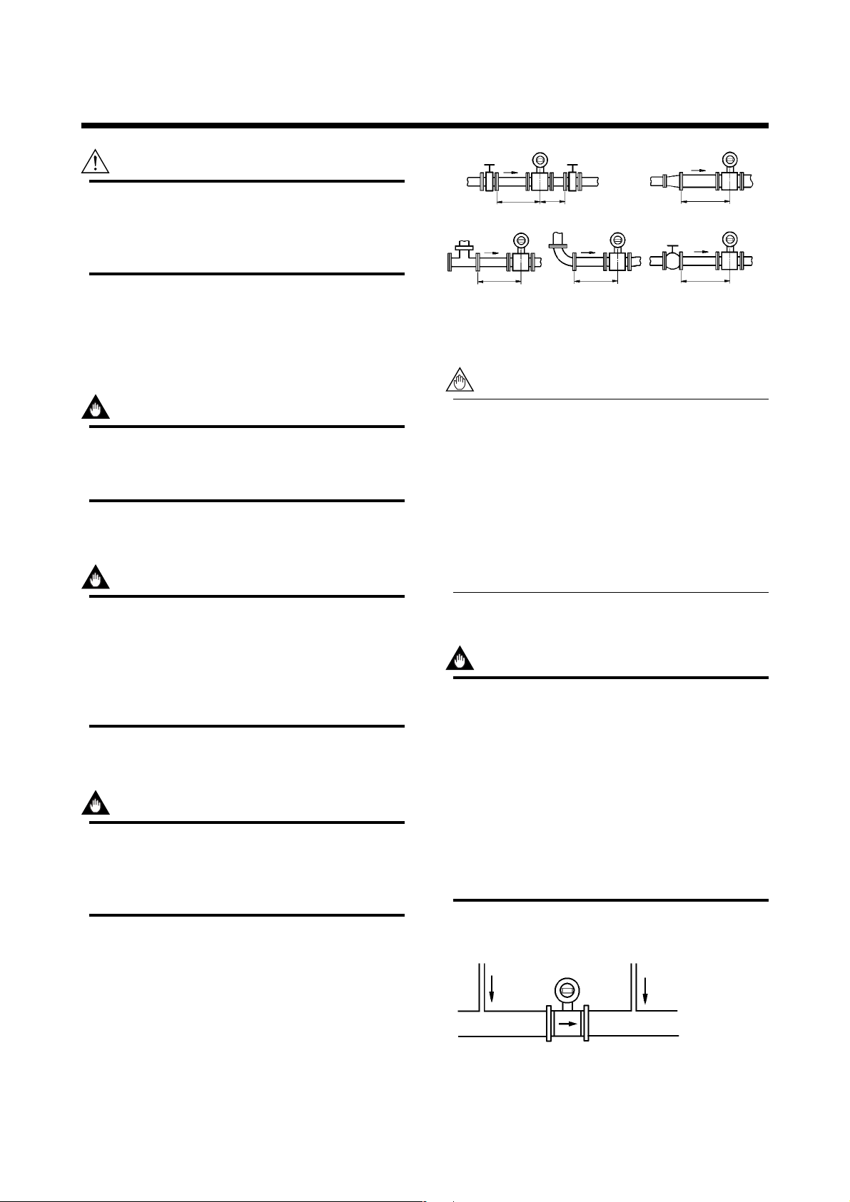
3.1 Piping Design Precautions
IMPORTANT
Please design the correct piping referring to the
followings to prevent damage for flow tube and
to keep correct measuring.
(1) Location
IMPORTANT
5 D or more 2 D or more
Gate valve fully open
5 D or more
D: Internal diameter of flowmeter
Figure 3.1.1 Minimum Length of Required Straight Run
Tee
5 D or more
90° bend
10 D or more
Expander pipe
10 D or more
Various types of valves
F0301.EPS
NOTE
1. Nothing must be inserted or installed in the
metering pipe that may interfere with the
magnetic field, induced signal voltages, and
flow velocity distribution.
2. These straight runs may not be required on
the downstream side of flowmeter. However,
if the downstream valve or other fittings
cause channeling on the upstream side,
provide a straight run of 2 D to 3 D on the
downstream side.
Please install the flow tube to the location where
it is not exposed to direct sunlight and ambient
temperature is –20 to + 60°C (–4 to 140°F)*.
* The minimum temperature is –10°C (14°F) in case
of the 40mm or lager sizes with the carbon steel
flange connection or wafer connection.
(2) Noise Rejection
IMPORTANT
The instrument should be installed away from
large electrical motors, transformers and other
power sources in order to avoid interference with
the measurement.
(3) Length of Straight Run
To keep accurate measuring, JIS B7554 “Electro
Magnetic Flow Tubes” explains about upstream piping
condition of Magnetic Flowmeters.
(4) Liquid Conductivity
IMPORTANT
Please avoid to install the flow tube at location
where liquid conductivity is likely to be nonuniform. Because it is possible to have bad
influences to the flow indication by non-uniform
conductivity when a chemical liquid is injected
from upstream side close to the flow tube. When
this occurs, it is recommended that chemical
application ports are installed on the downstream
side of the flow tube. In case chemicals must be
added upstream side, please keep the pipe
length enough so that liquid is properly mixed.
(BAD)
Upstream side
(GOOD)
Downstream side
We recommend to our customers about the piping
conditions shown in Figure 3.1.1 based on JIS B7554
and our piping condition test data.
Figure 3.1.2 Chemical Injection
3-1
F0302.EPS
IM 1E10B0-01E
Page 10
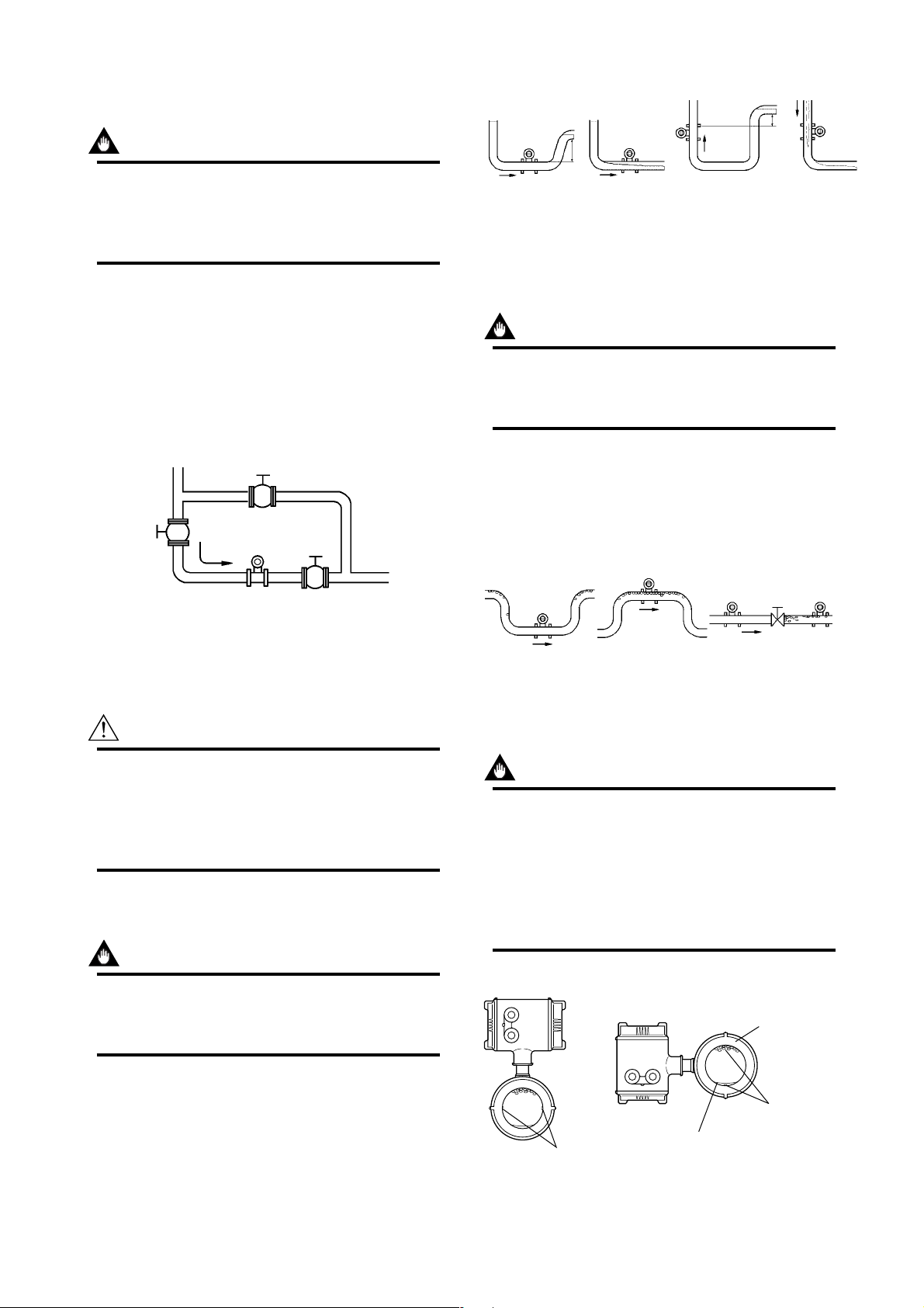
(5) Liquid Sealing Compound
(GOOD)
(BAD)
(GOOD)
(BAD)
h
h
h > 0
h > 0
Horizontal mounting
Vertical mounting
F0304.EPS
IMPORTANT
Please give attention in using Liquid Sealing
Compound to the piping, because it brings bad
influences to measurement by flowing out and
cover the surfaces of electrode and earth-ring.
(6) Service Area
Please select the location where there is enough area to
service installing, wiring, overhaul, etc.
(7) Bypass Line
It is recommended to install the Bypass Line to
facilitate maintenance and zero adjustment.
3. INSTALLATION
Figure 3.1.4 Filling the Pipe with Liquid
(10) No Air Bubbles
IMPORTANT
Please give attention to prevent bad influences
or measuring errors from air bubbles that gathers inside measuring pipes.
Bypass valve
Block valve
Block valve
Figure 3.1.3 Bypass Line
F0303.EPS
(8) Supporting the Flowmeter
CAUTION
Please avoid to support only the flowmeter, but
fix pipes at first and support the flowmeter by
pipes to protect the flow tube from forces caused
by vibration, shock, expansion and contraction
through piping.
(9) Piping Condition
In case the fluid includes air bubbles, please design the
piping that prevent to gather air bubbles. In case valves
are installed upstream of the flow tube, it is possible
that a valve causes air bubbles, please install the
flowmeter upstream side of a valve.
(GOOD)
(BAD)
Figure 3.1.5 Avoiding Air Bubbles
(GOOD)
(BAD)
F0305.EPS
(11) Mounting Direction
IMPORTANT
When the electrodes are vertical to ground, the
electrode is covered with air bubbles at upper
side or slurry at downside, and it may cause the
measuring errors.
Please be sure to mount the terminal box upper
side of piping to prevent water penetration into
terminal box.
The piping should be designed so that a full pipe
is maintained at all times to prevent loss of
signal and erroneous readings.
Please design the piping that a fluid is always filled in
the pipes. The Vertical Mounting is effective for fluids
that is easily separate or slurry settles within pipes.
In this case, please flow a fluid from bottom to up.
IMPORTANT
(GOOD) (BAD)
Air Bubbles
Electrodes
Slurry
Electrodes
Figure 3.1.6 Mounting Direction
3-2
F0306.EPS
IM 1E10B0-01E
Page 11
3. INSTALLATION
F0308.EPS
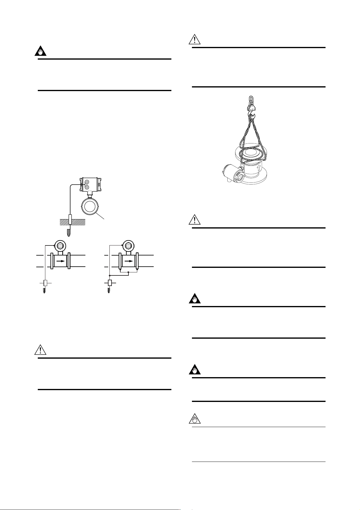
(12) Grounding
IMPORTANT
Improper grounding can have an adverse affect
on the flow measurement. Please ensure that
the instrument is properly grounded.
The electromotive force of the magnetic flow tube is
minute and it is easy to be affected by noise. And also
that reference electric potential is the same as the
measuring fluid potential. Therefore, the reference
electric potential (terminal potential) of the Flow Tube
and the Converter/Amplifier also need to be the same
as the measuring fluid. And moreover, that the potential must be the same with ground.
Please be sure to ground according to Figure 3.1.7.
600 V vinyl insulated
electric cable
(2mm2 or larger)
Note: See “3.4.1 Protective
grounding” for
information on
protective grounding.
CAUTION
In case the Magnetic Flow Tube without eye-bolt
lifts up, please refer to Figure 3.2.1. Please
never lift up by using a bar through the flow
tube. It damages liner severely.
Figure 3.2.1 Vertical Lifting Sling Rigging Method
(2) Precaution for Shock
Earth ring
Grounding resistance 100Ω or less
In case earth rings are used.
Figure 3.1.7 Grounding
In case earth rings are not used.
(Available only for metal piping)
F0307.EPS
3.2 Handling Precautions
WARNING
The Magnetic Flowmeter is a heavy instrument.
Please be careful to prevent persons from
injuring when it is handled.
CAUTION
Care should be taken not to drop the flow tube
or subject it to excessive shock. This may lead
to liner damage which will cause inaccurate
readings.
(3) Flange Protection Covers
IMPORTANT
Please keep the protection cover (ex. corrugated
paper or anything possible to protect) attached
with flange except when mounting to the pipe.
(4) Terminal Box Cover
IMPORTANT
Please never leave the terminal box cover open
until wiring to prevent insulation deterioration.
3.2.1 General Precautions
(1) Precaution for Carrying
The Magnetic Flowmeter is packed tightly. When it is
unpacked, please give attention to prevent damages to
the flowmeter. And to prevent the accident during
carry to the installing location, please carry it near the
location keeping packed as it delivered.
NOTE
The terminal box cover is locked by special
screw. In case of opening the terminal box
cover, please use the Hexagonal Wrench
attached.
3-3
IM 1E10B0-01E
Page 12

CAUTION
Be sure to lock the cover with the special screw
using the Hexagonal Wrench attached after
tightening the terminal box cover.
3. INSTALLATION
(5) Long-term Non-use
IMPORTANT
It is not preferable to leave the flowmeter for
long term non-use after installation.
In case the flow tube is compelled to do that,
please take care of the flowmeter by the followings.
• Confirmation of Sealing Condition for the
Flowmeter.
Please confirm the sealing conditions of the terminal
box screw and wiring ports.
In case of the Conduit Piping, please provide the
drain plugs or waterproof glands to it to prevent that
moisture or water penetrates into the flow tube
through the conduit.
• Regular Inspections
Please inspect the sealing condition (as above
mentioned) and inside of the terminal box. And
when it is suspect that water penetration into the
inside flow tube (ex. rain fall), please inspect when
it happened.
Slant
Figure 3.2.2 Slant and Mis-alignment of Flowmeter Piping
Mis-alignment
F0309.EPS
3.3 Mounting
3.3.1 Nominal Diameter 15mm (0.5in) to 40mm (1.5in) Wafer Type
IMPORTANT
Please use appropriate bolts and nuts according
to process connection. In case stud type of
through bolts are used, be sure outside diameter
of a shank is smaller than a thread ridge’s one.
Please use compressed non-asbestos fiber
gasket, PTFE gasket or the gasket which has
equal elasticity. In case of optional code/FRG,
please use rubber gasket or others which has
equal elasticity. Be sure the inner diameter of
the gasket does not protrude to inner piping.
(Refer to Table 3.3.6)
3.2.2 Flowmeter Piping
CAUTION
Mis-aligned or slanted piping can lead to leakage
and damage to flanges.
• Please correct mis-alignment or slanted piping and
improper distance between mounting flanges before
install the flowmeter. (Please refer to Figure 3.2.2)
• Inside a pipeline which is newly installed, some
foreign substances (such as welding scrap or wood
chips) may exist. Please remove them by flushing
piping before mounting the flowmeter.
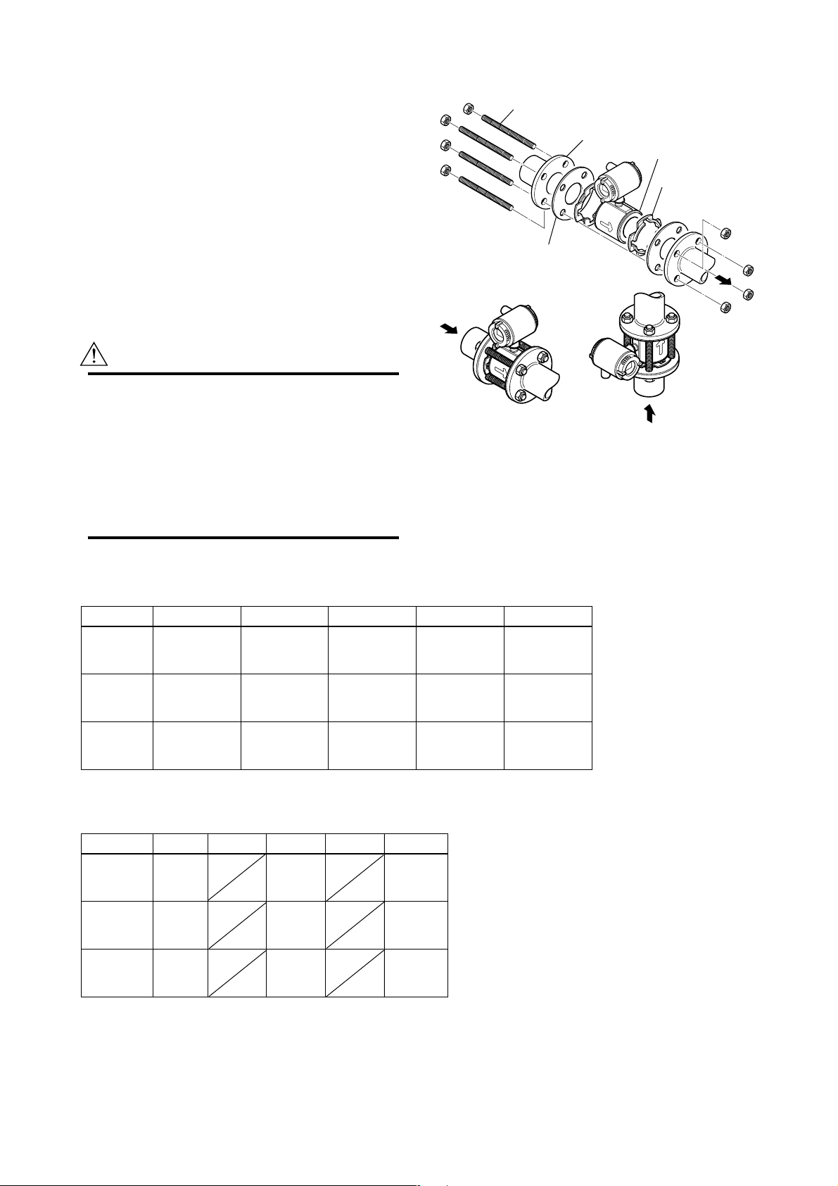
(1) Mounting Direction
Please mount the Magnetic Flowmeter matching the
flow direction of the fluid to be measured with the
direction of the arrow mark on the flowmeter.
IMPORTANT
If it is impossible to match the direction, please
never remodel by changing direction of the
terminal box. In case the measuring fluid flows
against the arrow direction, please refer to the
section 5.3.6 Reversing Flow Direction.
(2) Mounting Centering Devices
To keep concentricity of the Flow Tube with pipes,
please mount centering devices on the Mini-Flanges of
the Flow Tube. Please give attention to the nominal
diameter and flange rating of the centering devices.
3-4
IM 1E10B0-01E
Page 13
3. INSTALLATION
(3) Positioning Flow Tube
Please pass two through-bolts to adjacent holes of both
flanges and mount the Flow Tube, and pass other
through-bolts to other holes. (Refer to Figure 3.3.1) In
case stud type of through-bolts are used, position them
coming in contact centering devices with thread of
bolts.
(4) Tightening Nuts
Please tighten the bolts according to Torque Values in
Table 3.3.1. In case of PVC piping, please select
optional code /FRG, use rubber gasket and tighten with
the torque value in Table 3.3.2.
CAUTION
As the lining material is Fluorocarbon PFA, it is
possible that nuts may loose by its character as
time passes. Please tighten the nuts regularly.
Please be sure to tighten the bolts following
prescribed torque values. Please tighten the
flange bolts diagonally with the same torque
values, step by step up to the prescribed torque
value.
Please use appropriate bolts
Through-Bolt
and nut
Gasket
Figure 3.3.1 Mounting Procedure (Size: 15 mm(0.5in) to
40 mm(1.5in))
and nuts according to process
connection.
Flange
Mini-Flange
Centering Device
2-piece
Vertical MountingHorizontal Mounting
F0310.EPS
Table 3.3.1 Tightening Torque Values for Metal Piping in N-m{kgf-cm}[in-lbf]
Size mm(inch)
15(0.5)
25(1)
40(1.5)
*Please use compressed non-asbestos fiber gasket, PTFE gasket or the gasket which has equal elasticity.
Table 3.3.2 Tightening Torque Values for PVC Piping in N-m{kgf-cm}[in-lbf]
Size mm(inch)
15(0.5)
25(1)
40(1.5)
*Please select optional code /FRG and use rubber gasket or others which has equal elasticity.
JIS 10K JIS 20K ANSI 150 ANSI 300 DIN PN40
4.5 - 6.5
{46 - 66}
[40 - 58]
14.5 - 19.0
{148 - 194}
[128 - 168]
26.0 - 31.0
{265 - 316}
[230 - 274]
JIS 10K
1.3
{13}
[12]
3.5
{36}
[31]
5.7
{58}
[50]
JIS 20K ANSI 150
4.5 - 6.5
{46 - 66}
[40 - 58]
14.5 - 19.0
{148 - 194}
[128 - 168]
26.0 - 31.0
{265 - 316}
[230 - 274]
1.3
{13}
[12]
2.8
{29}
[25]
4.6
{47}
[41]
5.0 - 7.0
{51 - 71}
[44 - 62]
12.0 - 15.0
{122 - 153}
[106 - 133]
22.0 - 25.0
{224 - 255}
[195 - 221]
ANSI 300
DIN PN40
1.3
{13}
[12]
2.7
{28}
[24]
5.7
{58}
[50]
5.0 - 7.0
{51 - 71}
[44 - 62]
14.5 - 19.0
{148 - 194}
[128 - 168]
30.0 - 37.0
{311 - 377}
[270 - 327]
{51 - 66}
[44 - 58]
12.5 - 14.0
{128 - 143}
[111 - 124]
28.5 - 31.0
{291 - 316}
[252 - 274]
5.0 - 6.5
T0302.EPS
T0301.EPS
3-5
IM 1E10B0-01E
Page 14
3. INSTALLATION
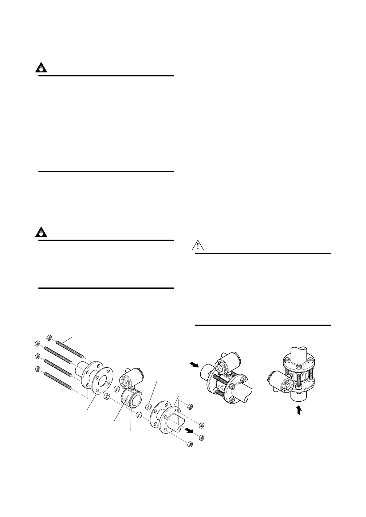
3.3.2 Nominal Diameter 50 mm(2in)
to 200 mm(8in) Wafer Type
IMPORTANT
Please use appropriate bolts and nuts according
to process connection. In case stud type of
through bolts are used, be sure outside diameter
of a shank is smaller than a thread ridge’s one.
Please use compressed non-asbestos fiber
gasket, PTFE gasket or the gasket which has
equal elasticity. In case of optional code/FRG,
please use rubber gasket or others which has
equal elasticity. Be sure the inner diameter of
the gasket does not protrude to inner piping.
(Refer to Table 3.3.6)
(1) Mounting Direction
Please mount the Magnetic Flowmeter matching the
flow direction of the fluid to be measured with the
direction of the arrow mark on the flowmeter.
(2) Mounting Centering Devices
To keep concentricity between the Flow Tube and
pipes, centering devices must be used. Pass two
through-bolts through the four centering devices (two
for each) and lower adjacent holes of both flanges.
(Refer to Figure 3.3.2)
Please give attention to the nominal size and flange
ratings of the centering devices. (Refer to Table 3.3.5)
(3) Positioning Flow Tube
Position the Flow Tube coming in contact four centering devices with Mini-Flanges. At this time, pay
attention to avoid four centering devices come in
contact with Housing. In case stud type of throughbolts are used, position them coming in contact four
centering devices with thread of the bolts. (Refer to
Figure 3.3.2) After positioning the Flow Tube, pass
remaining through-bolts to remaining holes.
(4) Tightening Nuts
Please tighten the bolts according to Torque Values in
Table 3.3.3. In case of PVC piping, please select
optional code/FRG, use rubber gasket and tighten with
the torque value in Table 3.3.4.
IMPORTANT
If it is impossible to match the direction, please
never remodel to change direction of the terminal box. In case the measuring fluid flows
against the arrow direction, please refer to the
section 5.3.6 Reversing Flow Direction.
Through-Bolt
and nut
Please use appropriate bolts and nuts
according to process connection.
Centering Device
CAUTION
As the lining material is Fluorocarbon PFA, it is
possible that nuts loose by its character as time
passes. Please tighten the nuts regularly.
Please be sure to tighten the bolts following
prescribed torque values. Please tighten the
flange bolts diagonally with the same torque
values, step by step up to the prescribed torque
value.
4-piece
Flange
Gasket
Housing
Mini-Flange
Figure 3.3.2 Mounting Procedure (Size: 50mm (2in) to 200mm (8in))
3-6
Horizontal Mounting
Vertical Mounting
F0311.EPS
IM 1E10B0-01E
Page 15

Table 3.3.3 Tightening Torque Values for Metal Piping in N-m{kgf-cm}[in-lbf]
Size mm(inch)
50(2)
80(3)
100(4)
150(6)
200(8)
JIS 10K JIS 20K ANSI 150 ANSI 300 DIN PN10
35.0 - 39.5
{357 - 403}
[310 - 350]
27.5 - 32.5
{281 - 332}
[243 - 288]
40.0 - 42.5
{408 - 434}
[354 - 376]
65.0 - 94.0
{663 - 959}
[575 - 832]
57.0 - 84.0
{581 - 857}
[504 - 743]
16.5 - 19.5
{168 - 199}
[146 - 173]
33.0 - 41.0
{337 - 418}
[292 - 363]
48.0 - 53.5
{490 - 546}
[425 - 473]
43.0 - 68.0
{439 - 694}
[381 - 602]
61.0 - 92.0
{622 - 938}
[540 - 814]
35.0 - 39.5
{357 - 403}
[310 - 350]
60.0 - 65.5
{612 - 668}
[531 - 580]
40.5 - 42.5
{413 - 434}
[358 - 376]
68.0 - 100.0
{694 - 1020}
[602 - 885]
69.0 - 101.0
{704 - 1030}
[611 - 894]
16.5 - 19.5
{168 - 199}
[146 - 173]
32.0 - 39.0
{326 - 398}
[283 - 345]
47.0 - 51.0
{479 - 520}
[416 - 451]
41.0 - 60.0
{418 - 612}
[363 - 531]
65.0 - 93.0
{663 - 949}
[575 - 823]
94.0 - 125.0
{959 - 1275}
[832 - 1106]
DIN PN16
27.5 - 32.5
{281 - 332}
[243 - 288]
40.0 - 42.5
{408 - 434}
[354 - 376]
65.0 - 94.0
{663 - 959}
[575 - 832]
58.0 - 84.0
{592 - 857}
[513 - 743]
3. INSTALLATION
DIN PN40
39.0 - 39.5
{398 - 403}
[345 - 350]
*Please use compressed non-asbestos fiber gasket, PTFE gasket or the gasket which has equal elasticity.
Table 3.3.4 Tightening Torque Values for PVC Piping in N-m{kgf-cm}[in-lbf]
Size mm(inch)
50(2)
80(3)
100(4)
150(6)
200(8)
JIS 10K
8.2
{84}
[73]
6.2
{63}
[55]
{82}
[71]
19.8
{202}
[175]
17.5
{179}
[155]
JIS 20K ANSI 150
8
8.2
{84}
[73]
12.4
{127}
[110]
8.1
{83}
[72]
18.9
{193}
[167]
25.1
{256}
[222]
ANSI 300
DIN PN10
26.2
{267}
[232]
DIN PN16
6.2
{63}
[55]
8
{82}
[71]
19.8
{202}
[175]
17.5
{179}
[155]
DIN PN40
8.2
{84}
[73]
*Please select optional code /FRG and use rubber gasket or others which has equal elasticity.
Table 3.3.5 Centering Device Identification
eziS
SIJ
K01
SIJ
K02
ISNA
051
ISNA
003
NPNID
01
DIN PN
NPNID
6104
50(2) B B B F - - F
80(3) B F F C - G -
100(4) B F C H - F -
150(6) K L K M - K -
200(8) K L L M K K
* Each Centering Device is engraved a character as identification.
-
T0305.EPS
* Please ensure that the I.D. of the gasket
does not protrude into the I.D. of the
Earth Ring. (This dimension is also
applied when no earth ring is used.)
Table 3.3.6 Earth Ring Inside Diameter
T0303.EPS
JIS G3451
F12(75M)
12.3
{126}
[109]
16.1
{164}
[142]
21.6
{220}
[191]
28.7
{293}
[254]
T0304.EPS
Unit:mm(inch)
Size Earth Ring inside diameter
15(0.5)
25(1)
40(1.5)
50(2)
80(3)
100(4)
150(6)
200(8)
15(0.59)
28(1.10)
41(1.61)
53(2.09)
81(3.19)
102(4.02)
146.1(5.75)
193.6(7.62)
T0306.EPS
3-7
IM 1E10B0-01E
Page 16
3. INSTALLATION
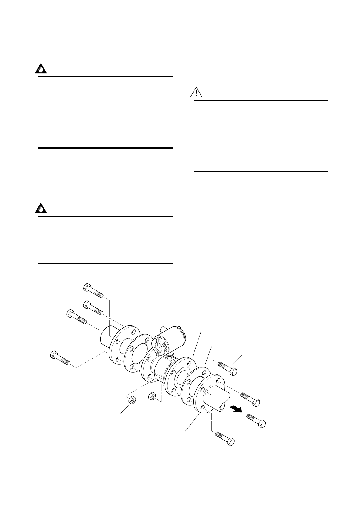
3.3.3 Nominal Diameter 15 mm (0.5in) to 200 mm (8in) Flange Type
IMPORTANT
Please use appropriate bolts and nuts according
to process connection. Please use compressed
non-asbestos fiber gasket, PTFE gasket or the
gasket which has equal elasticity. In case of
optional code /FRG, please use rubber gasket or
others which has equal elasticity. Be sure the
inner diameter of the gasket does not protrude to
inner piping. (Refer to Table 3.3.6)
(1) Mounting Direction
Please mount the Magnetic Flowmeter matching the
flow direction of the fluid to be measured with the
direction of the arrow mark on the flowmeter.
IMPORTANT
(2) Tightening Nuts
Please tighten the bolts according to Torque Values in
Table 3.3.7. In case of PVC piping, please select
optional code /FRG, use rubber gasket and tighten with
the torque value in table 3.3.8.
CAUTION
As the lining material is Fluorocarbon PFA, it is
possible that bolts loose by its character as time
passes. Please tighten the nuts regularly.
Please be sure to tighten the bolts following
prescribed torque values. Please tighten the
flange bolts diagonally with the same torque
values, step by step up to the prescribed torque
value.
If it is impossible to match the direction, please
never remodel to change direction of the terminal box. In case the measuring fluid flows
against the arrow direction, please refer to the
section 5.3.6 Reversing Flow Direction.
Please use appropriate bolts and
nuts according to process connection.
Flange
(Flow Tube)
Gasket
Bolt
Nut
Flange
(Piping side)
Figure 3.3.3 Mounting Procedure (Size: 15 mm (0.5in) to 200 mm (8in))
3-8
F0312.EPS
IM 1E10B0-01E
Page 17

Table 3.3.7 Tightening Torque Values for Metal Piping in N-m{kgf-cm} [in-lbf]
Size mm
JIS 10K
JIS 20K ANSI 150 ANSI 300 DIN PN10 DIN PN16
(inch)
DIN PN40
3. INSTALLATION
JIS F12(75M)
15(0.5)
25(1)
40(1.5)
50(2)
80(3)
100(4)
150(6)
200(8)
4.5 - 6.5
{46 - 66}
[40 - 58]
13.5 - 19.0
{138 - 194}
[119 - 168]
24.0 - 31.0
{245 - 316}
[212 - 274]
31.0 - 39.5
{316 - 403}
[274 - 350]
23.5 - 32.5
{240 - 332}
[208 - 288]
32.5 - 42.5
{332 - 434}
[288 - 376]
65.0 - 94.0
{663 - 959}
[575 - 832]
57.0 - 84.0
{581 - 857}
[504 - 743]
4.5 - 6.5
{46 - 66}
[40 - 58]
13.5 - 19.0
{138 - 194}
[119 - 168]
24.0 - 31.0
{245 - 316}
[212 - 274]
15.0 - 19.5
{153 - 199}
[133 - 173]
28.5 - 41.0
{291 - 418}
[252 - 363]
40.0 - 53.5
{408 - 546}
[354 - 473]
43.0 - 68.0
{439 - 694}
[381 - 602]
61.0 - 92.0
{622 - 938}
[540 - 814]
4.5 - 7.0
{46 - 71}
[40 - 62]
11.5 - 15.0
{117 - 153}
[102 - 133]
20.0 - 25.0
{204 - 255}
[177 - 221]
32.0 - 39.5
{326 - 403}
[283 - 350]
53.5 - 65.5
{546 - 668}
[473 - 580]
34.5 - 42.5
{352 - 434}
[305 - 376]
68.0 - 100.0
{694 - 1020}
[602 - 885]
69.0 - 101.0
{704 - 1030}
[611 - 894]
4.5 - 7.0
{46 - 71}
[40 - 62]
14.0 - 19.0
{143 - 194}
[124 - 168]
28.0 - 37.0
{286 - 377}
[248 - 327]
15.0 - 19.5
{153 - 199}
[133 - 173]
28.5 - 39.0
{291 - 398}
[252 - 345]
40.0 - 51.0
{408 - 520}
[354 - 451]
41.0 - 60.0
{418 - 612}
[363 - 531]
65.0 - 93.0
{663 - 949}
[575 - 1106]
94.0 - 125.0
{959 - 1275}
[832 - 1106]
23.5 - 32.5
{240 - 332}
[208 - 288]
33 - 42.5
{337 - 434}
[292 - 376]
65.0 - 94.0
{663 - 959}
[575 - 832]
58.0 - 84.0
{592 - 857}
[513 - 743]
* Please use compressed no-asbestos fiber gasket, PTFE gasket or the gasket which has equal elasticity.
4.5 - 6.5
{46 - 66}
[40 - 58]
11.5 - 14.0
{117 - 143}
[102 - 124]
25.5 - 31.0
{260 - 316}
[226 - 274]
34.5 - 39.5
{352 - 403}
[305 - 350]
51.0 - 65.5
{520 - 668}
[451 - 580]
72.0 - 85.0
{734 - 867}
[637 - 752]
68.0 - 100.0
{694 - 1020}
[602 - 885]
69.0 - 101.0
{704 - 1030}
[611 - 894]
T0307.EPS
Table 3.3.8 Tightening Torque Values for PVC Piping in N-m{kgf-cm} [in-lbf]
Size mm
JIS 10K
JIS 20K
ANSI 150 ANSI 300 DIN PN10
DIN PN16
DIN PN40
(inch)
15(0.5)
25(1)
40(1.5)
50(2)
80(3)
100(4)
150(6)
200(8)
1.3
{13}
[12]
3.5
{36}
[31]
5.7
{58}
[50]
8.2
{84}
[73]
6.2
{63}
[55]
8
{82}
[71]
19.6
{200}
[173]
17.5
{179}
[155]
1.3
{13}
[12]
2.8
{29}
[25]
4.6
{47}
[41]
8.2
{84}
[73]
12.4
{127}
[110]
8.1
{83}
[72]
18.8
{192}
[166]
25.1
{256}
[222]
26.2
{267}
[232]
1.3
{13}
[12]
2.7
{28}
[24]
5.7
{58}
[50]
8.2
{84}
[73]
6.2
{63}
[55]
8
{82}
[71]
19.6
{200}
[173]
17.5
{179}
[155]
* Please select optional code /FRG and use rubber gasket or others which has equal elasticity.
JIS G3451
F12(75M)
12.3
{126}
[109]
16.1
{164}
[142]
21.5
{219}
[190]
28.7
{293}
[254]
T0308.EPS
3-9
IM 1E10B0-01E
Page 18
3. INSTALLATION
3.4 Wiring Precautions
CAUTION
Confirm that all connections are corrected before
applying power to the instrument. Improper
wiring may damage the flowmeter.
NOTE
The terminal box and display cover is locked by
special screw. In case of opening the terminal
box cover, please use the Hexagonal Wrench
attached.
CAUTION
Be sure to lock the cover with the special screw
using the Hexagonal Wrench attached after
tightening the terminal box cover.
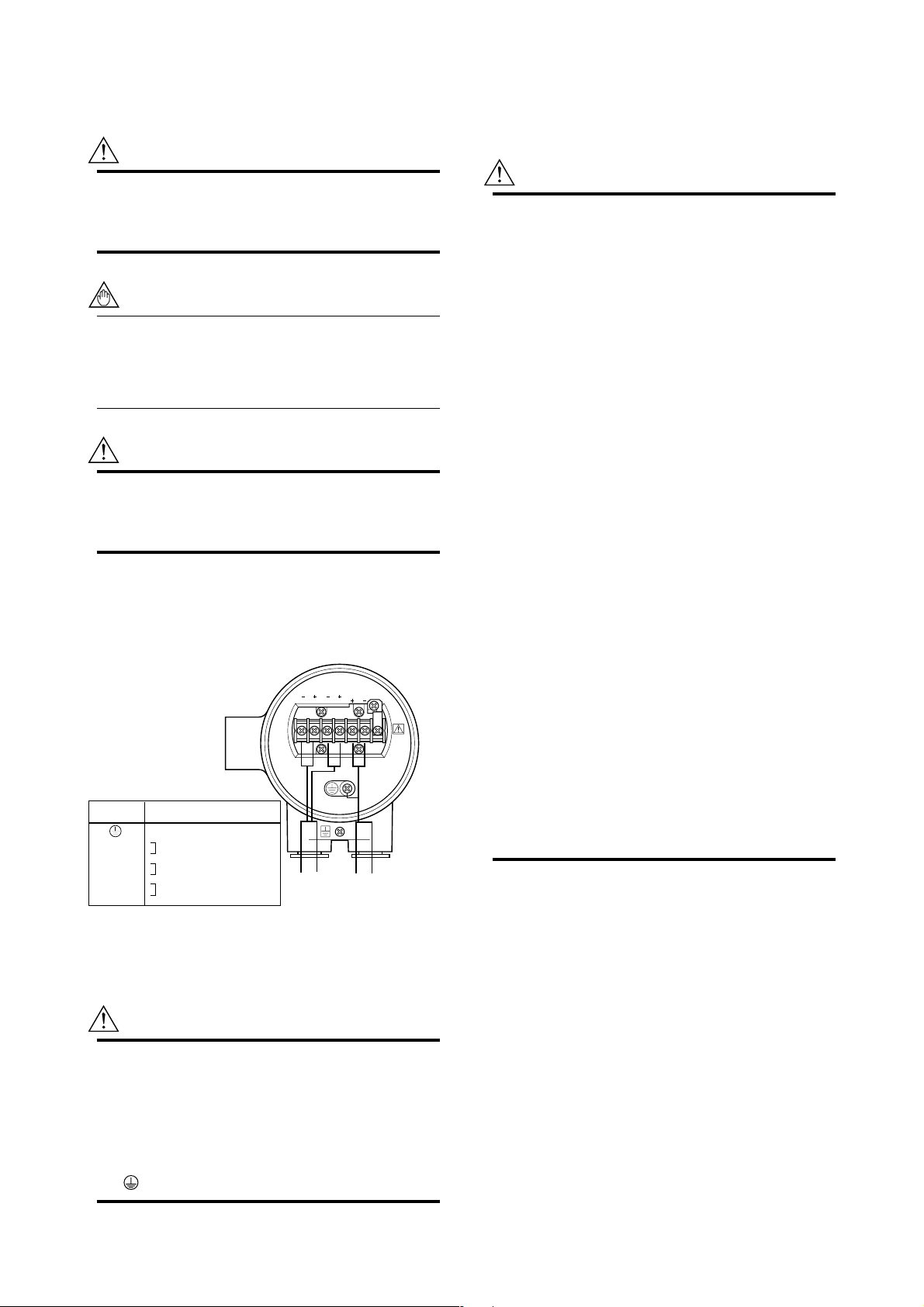
The external signal wirings are connected into the
terminal inside the converter. Please connect to each
terminal (Please refer to Figure 3.4.1) by taking off a
cover backside the converter.
PLS/ALM CUR POWER
Terminal
Symbols
POWER N–
POWER L+
CUR+
CUR–
PLS/ALM+
PLS/ALM–
Figure 3.4.1 WWiring
Description
Protective grounding
Power Supply
Current Output 4 to 20mA DC
Pulse, alarm or status output
Output
Cable
3.4.1 Protective Grounding
CAUTION
Please be sure to connect protective grounding
of ADMAG SE with cable of 2mm2 or larger
cross section in order to avoid the electrical
shock to the operators and maintenance engineers and prevent the influence of external
noise. And further connect the grounding wire to
the mark (100Ω or less).
LN
Power
Cable
G
F0313.EPS
3.4.2 General Precautions
Please give attention to the followings in wiring.
CAUTION
• Please pay attention to avoid the cable is
bended excessively.
• Please do not connect cables outdoors in case
of rain to prevent damages from dew formation
and to keep insulation inside the terminal box
of the flowmeter.
• The all cable ends are to be provided with
round crimp-on terminal.
• The power cables and output signal cables
must be routed in separate steel conduit tubes
or flexible tubes.(except 4-core 24VDC cable
wiring.)
• When waterproof glands or union equipped
waterproof glands are used, the glands must be
properly tightened to keep the box watertight.
•Please install a external switch or circuit
breaker as a means of power off (capacitance;
15A, conform to IEC947-1 and IEC947-3). The
preferable location is either near the instrument
or other places to easy operation. Furthermore, please indicate “power off equipment” on
the those external switch or circuit breaker.
• Please be sure to fully tighten the terminal box
cover before the power is turned on. After
tightening the covers, please be sure to fix it
withh the special screw using a hexagonal
wrench attached.
• Please be sure to turn off the power before
opening the covers.
• In case of DC power supply, a plug is attached.
When 4-core cable is used, please put that
plug into unused electrical connection port.
3.4.3 Power and Output Cables
Power Cable:
• Crimp-on Terminal
• Green/Yellow covered conductors shall be used only
for connection to PROTECTIVE CONDUCTOR
TERMINALS.
• Conform to IEC277, IEC245 or equivalent national
authorization.
Output Cable:
• Please use Polyvinyl chloride insulated and sheathed
control cables (JIS C3401) or Polyvinyl chloride
insulated and sheathed portable power cables (JIS
C3312) or equivalents.
3-10
IM 1E10B0-01E
Page 19
3. INSTALLATION
Outer Diameter:
•6.5 to 12mm in diameter (10.5 to 11.5mm for
waterproof gland /ECG, /ECU)
Nominal Cross Section:
• Single wire; 0.5 to 2.5mm2 , Stranded wire; 0.5 to
2
2.5mm
3.4.4 DC Connections
(1)Connecting Power Supply
IMPORTANT
In case of 24VDC power supply, AC power
supplies or reversed polarities cannot be connected. It will cause the fuse to burn out.
IMPORTANT
In case of 24VDC power supply, the specification for the supply voltage is 24VDC (-15 to
+20%), but the input voltage of the converter
drops due to cable resistance so it should be
used within the following range.
3.4.5 Wiring Ports
Please select the most suitable standard of wiring
procedure for the wiring ports by customer’s own.
(1)Using the Waterproof Gland
IMPORTANT
To prevent water or condensate from entering
the converter housing, waterproof glands are
recommended. Do not over-tighten the glands or
damage to the cables may result. Tightness of
the gland can be checked by confirming that the
cable is held firmly in place.
Waterproof gland
Optional specification code : /ECG
Gasket
Tightening gland
Washer
Waterproof gland with union joint
Optional specification code : /ECU
G 1/2
Gasket
1000
(3300)
900
(2970)
800
(2640)
700
(2310)
m(ft)
600
(1980)
500
(1650)
400
(1320)
300
(990)
200
(660)
100
(330)
0
20 22 24 26 28
Allowed
cable
length
Figure 3.4.2 Supplied Power and Cable Length
Supplied Power and Cable Length
Usable range E(V)
Cable cross section area : 1.25mm
Cable cross section area : 2mm
2
2
F0314.EPS
(2)Setting Power Supply Frequency
IMPORTANT
In case of DC power supply, the frequency of
the power supply has to be adjusted. Please
adjust for the local power frequency. The power
supply frequency is set in parameter B12 (or
Power freq for HART). Refer to 5.2, 6.5.2, or
7.3.4 for data setting procedure.
Tightening gland
G 1/2
Figure 3.4.3 Waterproof Gland
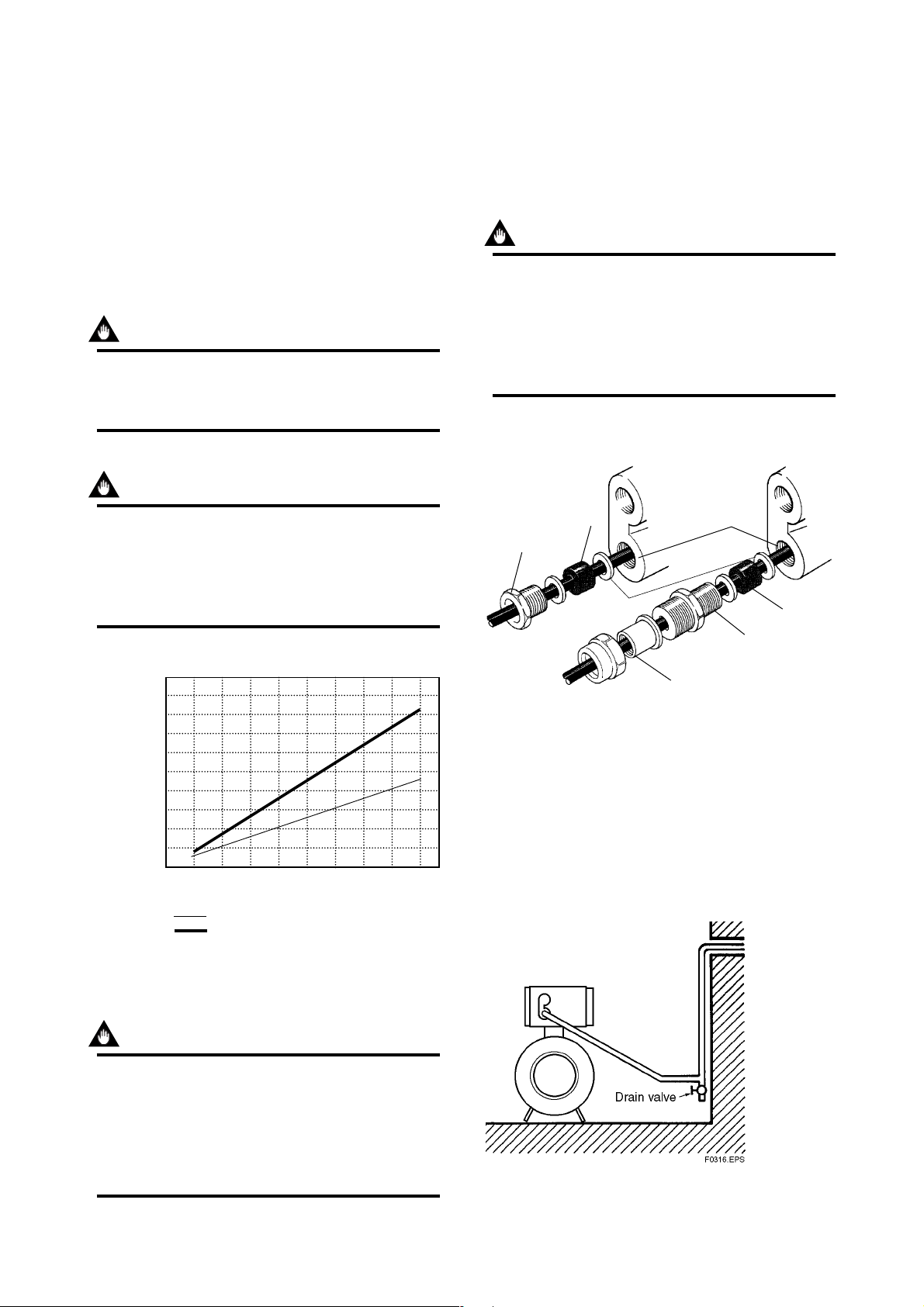
(2)Conduit Wiring
In case of conduit wiring, please use the waterproof
gland to prevent water flowing through the conduit
pipe into the wiring connection.
Please slope the conduit pipe down, and install a drain
valve at the low end of the vertical pipe.
Please open the drain valve regularly.
Figure 3.4.4 Conduit Wiring
3-11
F0315.EPS
IM 1E10B0-01E
Page 20
3. INSTALLATION
3.4.6 Connecting to External Instru-
ments
CAUTION
All the devices to be connected to current output
and pulse output must be conformed to
CSA1010, CSA950, or IEC950.
(1)Analog Signal Output(4 to 20mADC)
+
CUR+
ADMAG SE
–
CUR–
Figure 3.4.5 Connection for Analog Signal Output
(2)Pulse Output
+
RECEIVER
–
Load Resistance
max. 600 Ω
F0317.EPS
(3)Alarm or Status Output
IMPORTANT
This is a transistor contact(insulated type) so
attention must be paid to volttage and polarity
when making connections.
This output can not switch an AC load. To do
this, another relay (see the figure below) is
required.
* The alarm output works from “close”(Normal) to
“open”(Alarm).
ADMAG SE
ADMAG SE
PLS/ALM+
PLS/ALM–
PLS/ALM+
Protective diode
Load
This connection cannot
be made.
IMPORTANT
Please give attention to voltage and polarity in
wiring, because it is transister contact(insulation
type.
• In case of the filtering constant of Electric
Counter is more than the pulse width, it makes
signal decreases and can not be calculated
correctly.
• In case of input impedance of electric counter
is large inductive noise from power supply bring
bad influence to measurement. To calculate
correctly, it is recommended to use shield cable
or to make input impedance small enough
within the limits of pulse output of flowmeter.
ADMAG SE
PULSE OUT
PLS/ALM+
+
–
PLS/ALM–
Protective diode
Mechanical counter
30 V DC, 0.2A. max
PLS/ALM–
External
Power supply
30 V DC, 0.2A. max
Figure 3.4.7 Contact Output Connection
Magnetic
valve
AC power supply
F0319.EPS
ADMAG SE
PULSE OUT
Figure 3.4.6 Pulse Output Connection
PLS/ALM+
+
–
PLS/ALM–
Load
Universal counter or
Electronic counter
F0318.EPS
3-12
IM 1E10B0-01E
Page 21
4. BASIC OPERATING PROCEDURES
4. BASIC OPERATING PROCEDURES
All data settings can be performed with the three keys on the front panel (SET,SHIFT,
and INC), or using a handheld Brain Terminal (BT) or using a HART communicator.
The following sections describe basic data components and how to use the three panel
keys. (Please refer to Chapter 6 for the operation via Brain Terminal and Chapter 7 for
the operation via HART communicator.)
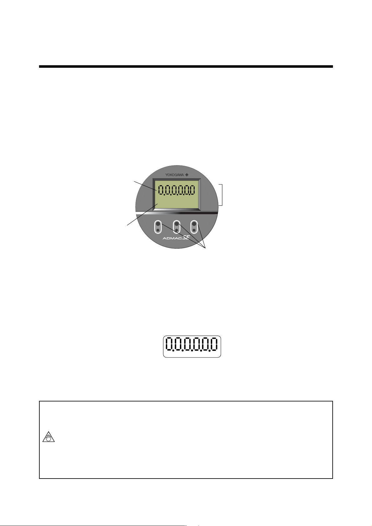
4.1 Liquid Crystal Display (LCD)
ADMAG SE display panel (if equipped) shows the components as follows.
4:Decimal Point
1:Data Display
3:Unit Display
µMmNkgalbbl %
scftm3 /d /s /h /m
SET
SHIFT
INC
2:Infrared Switches (if equipped)
Figure 4.1Components of Display
1: Data Display: Displays flow rate data, setting data and type of alarm generated.
2: Infrared Switches: These keys are used to change the display and type of setting data.
3: Unit Display: Displays flow rate units. In order to display other units, the
required unit label should be selected from the provided data
sheets.
4: Decimal Point: Displays decimal point.
• Structure of the Display
* The Display consists of six figure and five dots for the decimal point between them.
* Two types of data can be entered : direct entry of numerals and entry of desired data
items using codes.
Please refer to Chapter 11. Parameter List for information on how to change settings.
NOTE
The infrared switches operates as “ON” status by detecting the infrared ray reflection
from a finger put over the switches through the glass plate of the cover. Switches are
just below the printed letters SET, SHIFT, or INC on the faceplate and are circled
with a white line.
When you “touch” the swiches, please note the follwing.
The switches may operate even when you don’t touch the glass plate if your finger
comes near just above the glass plate. so please touch the switches sliding in your
finger from the lower part of the glass plate. Also be sure not to touch more than
one switch at one time by covering your other fingers over the faceplate.
4-1
IM 1E10B0-01E
Page 22
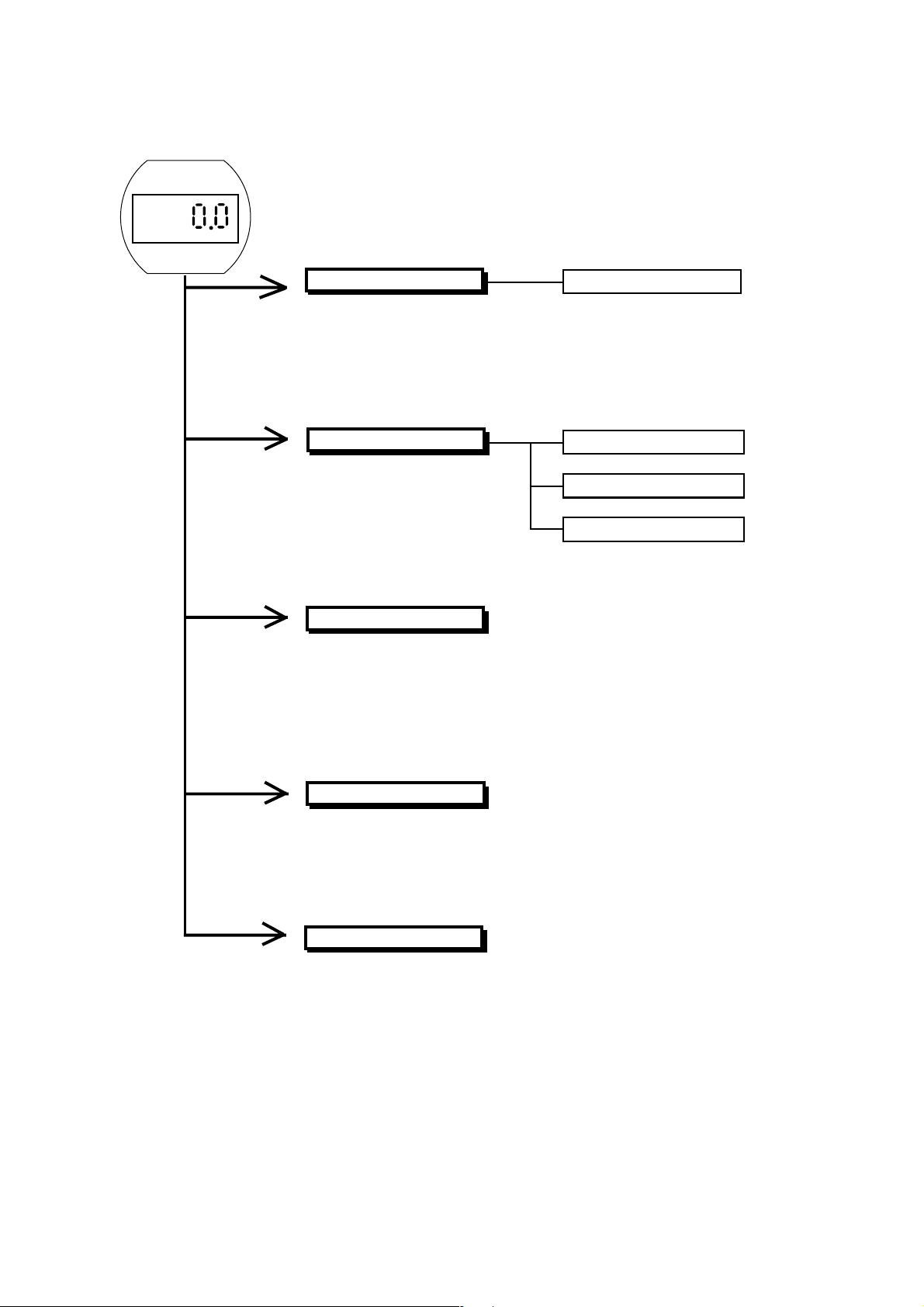
4.2 Types of Display Data
The Display Data is divided into 5 types as follows.
4. BASIC OPERATING PROCEDURES
Please refer to section 4.2.2
Flow Rate Display Mode
This mode indicates the instantaneous flow rate and totalization data.
Display settings can be set in the Setting Mode and parameter
No.“d01” (DISP SELECT) by using infrared switches, Brain Terminal,
or HART communicator.
Setting Mode
This mode makes certain about
contents of parameter and
rewrite data.This mode is called
up from Flow Rate Display Mode
by touching the SET key for 3
sec. and inputting a password.
Alarm Display Mode
When an alarm occurs in the
Flow Rate Display Mode, this
mode indicates the alarm code
number and normal data
alternately.
Please refer to section 4.2.4
Pass-Word Input Mode
Please refer to section 4.2.3
Number Changing Mode
Data Changing Mode
Data Confirmation Mode
Auto Zero Mode
This mode is indicated during
automatic zero setting.
Indicator Error Mode
This mode is shown in case the
keys keep staying “ON” by stains
or obstacles on front glass of the
case.The error is canceled by
cleaning them.
4-2
Please refer to section 4.2.5
Please refer to section 4.2.6
IM 1E10B0-01E
Page 23
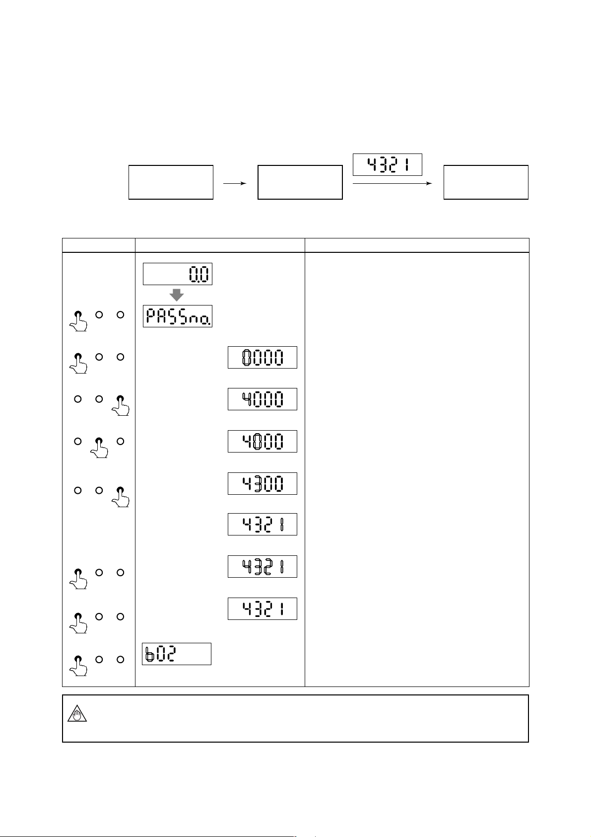
4.2.1 The Initial Procedure to Change the Display Mode
•The procedure of changing the display from the Flow Rate Display Mode into the
Setting Mode by using infrared switches on the converter is described as follows.
(1) Procedure in General
4. BASIC OPERATING PROCEDURES
The Flow Rate
Display Mode
SET key
(for 3 sec.)
The Pass-word
Input Mode
Password Input
(It is always “4321”.)
(2) Procedure in Detail
Switch Operation Display Description
(After power on)
SET SHIFT INC
(for 3 sec.)
SET SHIFT INC
SET SHIFT INC
SET SHIFT INC
(example)
To go to the Setting Mode, it is needed to go to the Password
Input Mode first. Please touch the SET key for 3 sec., and the
display goes into the Password Input Mode.
By touching the SET key again, the display goes into the
Number Input Mode. Please input the Password as follows, by
touching the SHIFT and INC keys.
By touching the INC key for some moment, change “0” into
“4”.
By touching the SHIFT key, the cursor moves to the next digit.
The Setting
Mode
SET SHIFT INC
SET SHIFT INC
SET SHIFT INC
SET SHIFT INC
NOTE
By touching the INC key for some moment again, change “0”
into “3”.
By continuing this for the rest of two digits, please change the
whole digits into “4321”.
By touching the SET key, whole Display is blinking.
And by touching the SET key again, setting the password is
completed.
(Setting is now completed)
By touching the SET key again, the display goes to the number
changing mode.
In the Password Input Mode, if keys were not operated for more than 20 sec., or if
correct password were not set, the display goes back into the Flow Rate Display Mode
automatically.
4-3
IM 1E10B0-01E
Page 24
4. BASIC OPERATING PROCEDURES
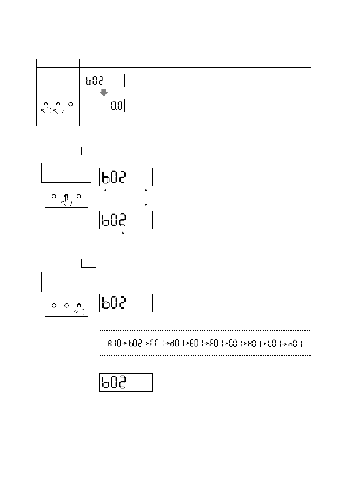
• The procedure of returning from the Setting Mode to the Flow Rate Display
Mode by using infrared switch on the converter is described as follows.
Switch Operation Display Description
The number changing mode of the Setting Mode.
SET SHIFT INC
(SHIFT key first)
(1) Functions of
Number
Changing Mode
SET SHIFT INC
(2) Functions of
Number
Changing Mode
(example)
After all settings have been completed, touch the SET key
simultaneously while touching the SHIFT key. Then the display
goes back to the Flow Rate Display Mode.
• Additional information on the functions of the keys is described here.
SHIFT
key
When the SHIFT key is touched in the Number Changing Mode, it shows as follows.
<< The Cursor Position moves alternately by touching the
SHIFT key.
Cursor Position
Cursor Position
key
INC
The INC key in the Number Changing Mode has each working at each cursor position.
a) In case the Cursor Position is at upper figure
SET SHIFT INC
The parameter number changes the followings by touching the INC key.
b) In case the Cursor Position is at lower figure
The parameter number changes from small number to big one by touching the INC key.
For example; 02, 03,
...
, 37, 02, 03,
...
(in case of parameters with “b”)
4-4
IM 1E10B0-01E
Page 25

4.2.2 Flow Rate Display Mode
• Flow Rate Display Mode indicates flow rates and totalization data. ADMAG SE can
indicate 12 types as follows.
INDICATOR
DISPLAY ITEM CONTENTS BT200 SETTING
Flow Rate (%)
Flow Rate
Actual Flow Rate
Instantaneous flow rate is displayed
within a range of -8 (or –108%) to
108% for the span.
The actual meter rate of instataneous
flow rate is displayed. (See NOTE)
The decimal place is the same as for
the span setting. However, since a
decimal point set at the least
significant bit cannot be displayed.
Parameter
No.
d01
d01
Code
No.
D01: DISP SELECT
00
D01: DISP SELECT
01
4. BASIC OPERATING PROCEDURES
HART
Communicator
RATE(%)
RATE
Disp Select
PV % rnge
Disp Select
PV
Actual Flow Rate
Totalization Values
Reverse Flow Rate
Totalization Values
Differential Between the
Forward and Reverse Flow
Totalization Values
Alternate Display of Flow Rate
(%) and Forward Flow Rate
Totalization Values
Alternate Display of Actual
Flow Rate and Forward Flow
Rate Totalization Values
Alternate Display of Actual
Flow Rate and Forward Flow
Rate(%)
Alternate Display of Flow Rate
(%) and Reverse Flow
Totalization Values
Alternate Display of Forward
Flow Rate and Reverse Flow
Totalization Values
Alternate Display of Flow Rate
(%) and Differential Flow
Totalization Values
Alternate Display of Forward
Flow Rate and Differential
Flow Totalization Values
Display actual flow rate totalization
value
Display reverse flow rate totalization
value
Differential totalization between
forward totalization and reverse
totalization is displayed.
Display alternately between display
of “RATE(%)” and “FOR. TTL”
every 4 second interval.
Display alternately between display
of “RATE” and “FOR. TTL”.
Display alternately between display
of “RATE” and “RATE(%)” every 4
second interval.
Display alternately between display
of “RATE(%)” and “REV. TTL”
every 4 second interval.
Display alternately between display
of “RATE” and “REV. TTL” every 4
second interval.
Actual flow rate (%) and differential
between forward and reverse
totalization values are indicated
alternately every 4 sec.
Actual flow rate and forward and
reverse totalization values are
indicated alternately every 4 sec.
d01
d01
d01
d01
d01
d01
d01
d01
d01
d01
D01: DISP SELECT
02
D01: DISP SELECT
03
D01: DISP SELECT
04
D01: DISP SELECT
05
D01: DISP SELECT
06
D01: DISP SELECT
07
D01: DISP SELECT
08
D01: DISP SELECT
09
D01: DISP SELECT
10
D01: DISP SELECT
11
FOR. TOT AL
REV. TOT AL
DIF. T OTAL
RATE %/FOR TTL
RATE/FOR TTL
RATE/RATE %
RATE %/REV. TTL
RATE/REV . TTL
RATE %/DIF. TTL
RATE/DIF. TTL
Disp Select
Totl
Disp Select
Rev. totl
Disp Select
Diff. totl
Disp Select
PV % rnge/Totl
Disp Select
PV/Totl
Disp Select
PV % rnge/PV
Disp Select
PV % rnge/Rev. totl
Disp Select
PV/Rev. totl
Disp Select
PV % rnge/Diff. totl
Disp Select
PV/Diff. totl
NOTE
• The display can set the units by setting parameter No.“b04” and “b05”.
• When special display of flow rate is specified in parameter “d10 flow user unit”, this
special display has higher priority in displaying than actual flow rate.
•Those 12 types function can be selected and set by changing into the Setting Mode.
(Please refer to 4.2.3 Setting Mode.)
• Those 12 types function can be selected by using infrared switches, Brain Terminal,
or HART communicator. (For using BT, please refer to Chapter 6. OPERATION VIA
BRAIN TERMINAL(BT 200). For using HART communicator, Chapter 7. OPERATION VIA HART Communicator.)
4-5
IM 1E10B0-01E
Page 26
4.2.3 Setting Mode
The Setting Mode confirms contents of parameter and rewrite data.
Number
Changing Mode
Cursor position is blinking.
4. BASIC OPERATING PROCEDURES
• Detailed procedures of data setting are explained in “ Chapter 5. Function and Data
Settings”.
• Procedure of data setting
* When the display is in the Setting Mode just after power
ON, it always starts from “b02”.
* After that, it starts from the former selected number.
SET SHIFT INC SET SHIFT INC
*Keys for number changing
SHIFT: for changing positions (to the right)
INC: for changing alphabets or numerals
SET SHIFT INC
Data Changing
Mode
*By touching the SET key the display goes to the Data Changing Mode.
* Two types of data can be entered : direct entry of numerals and entry of desired data
items using codes. Please refer to “Chapter 11. Parameter List” for information on
how to change settings.
SET SHIFT INC SET SHIFT INC
* Keys for data changing
SHIFT: for changing positions (to the right)
INC: for changing numerals or the position of
decimal point
*Data types are as follows.
Direct entry of numerals Entry of selected number
5-figure data = A decimal point is sure to show somewhere, The last figure (6th figure)
is always SPACE.
6-figure data(totalized value) = A decimal point doesn't show anywhere and no SPACE.
Selection type data = It is always 2-figure(other figures are always SPACE).
SET SHIFT INC
Data Confirmation
Mode
SET SHIFT INC
SET SHIFT INC
Whole display is blingking.
Data is completed.
The marks are always shown at the highest figure.
It changes: “+” and “–” (“+” is shown as “ ”.)
*When it is the Data Changing Mode and touch SET key, it
changes into the Data Confirmation Mode, whole of the
display begins to blink.
* During the display is blinking, touch the SET key, then the
data is completed.
* Then touch the SET key again and the display goes back to
the Number Changing Mode.
* During the display is blinking and touch other keys except
the SET key, the data setting is canceled and the display
goes back to the Number Changing Mode.
4-6
IM 1E10B0-01E
Page 27
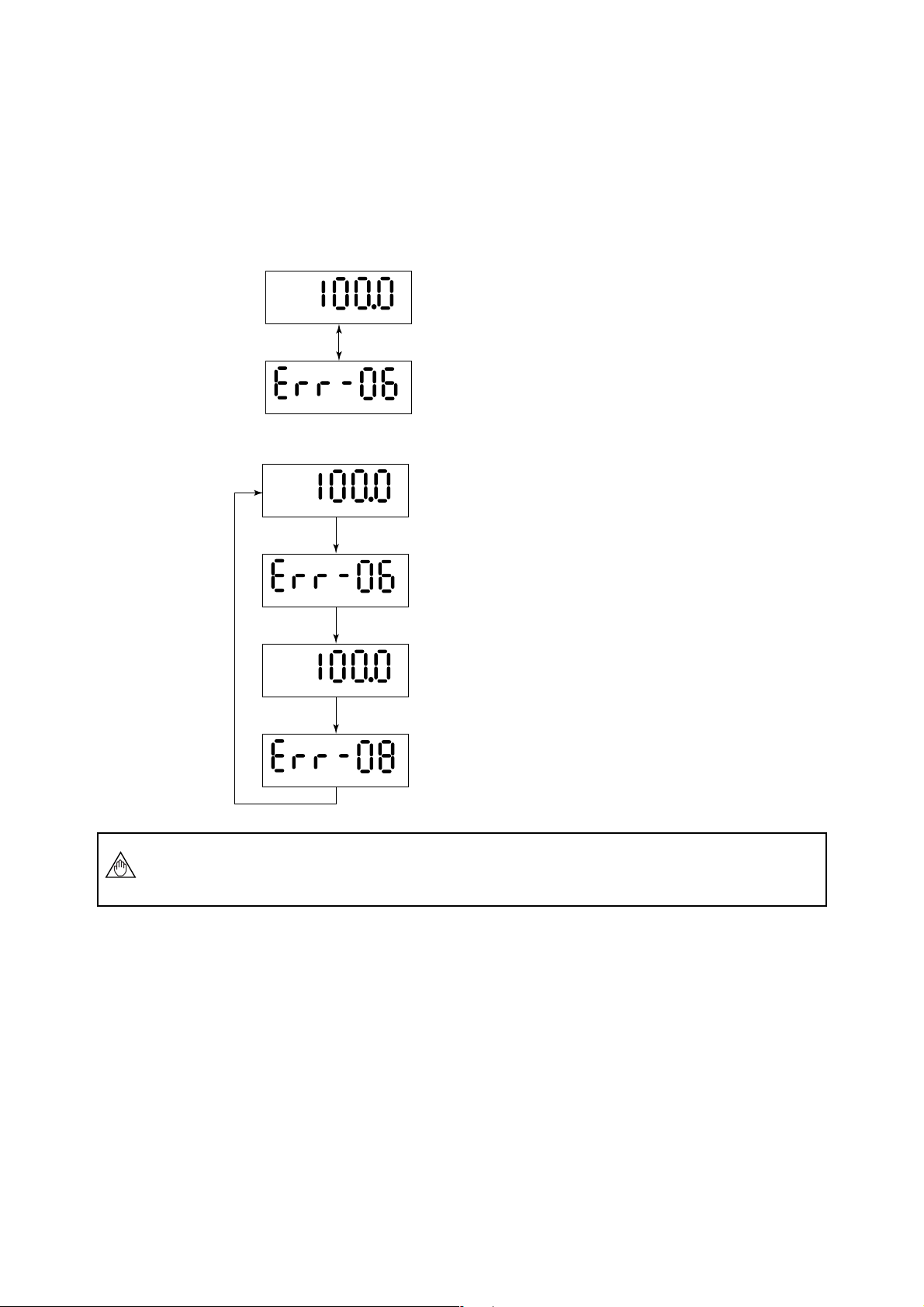
4.2.4 Alarm Display Mode
• When an alarm occurs, a content of the alarm is shown as an alarm code number.
However, this mode is available during the Flow Rate Display Mode.
In this mode, alarm number and flow rate are shown alternately.
For example;
• When alarm No. 6 is raised.
• When alarm No.6 and No.8 are raised at the same time.
4. BASIC OPERATING PROCEDURES
<< Flow Rate is indicated for 4 sec.
%
<< Alarm No. is indicated for 2 sec.
<< Flow Rate is indicated for 4 sec.
%
NOTE
<< Alarm No.6 is indicated for 2 sec.
<< Flow Rate is indicated for 4 sec.
%
<< Alarm No.8 is indicated for 2 sec.
For further description of the alarm functions, please refer to “Chapter 8.2 Selfdiagnostics Functions”.
4-7
IM 1E10B0-01E
Page 28
4.2.5 Auto Zero Mode
•Three ways of the auto zero adjustment can be done by using the infrared switches on
the converter, BT Terminal, or HART communicator.
Please refer to “8.1 Pre-Operation Zero Adjustment” in detail.
• The display can be changed into the Auto Zero Mode from any mode.
• The Auto Zero Mode is shown as follows (for 20sec.).
• When the Auto Zero Mode is finished, the display goes back into the Flow Rate
Display Mode automatically.
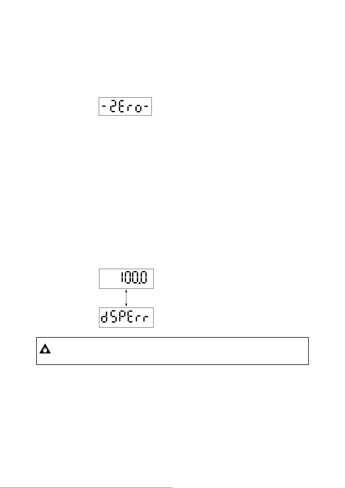
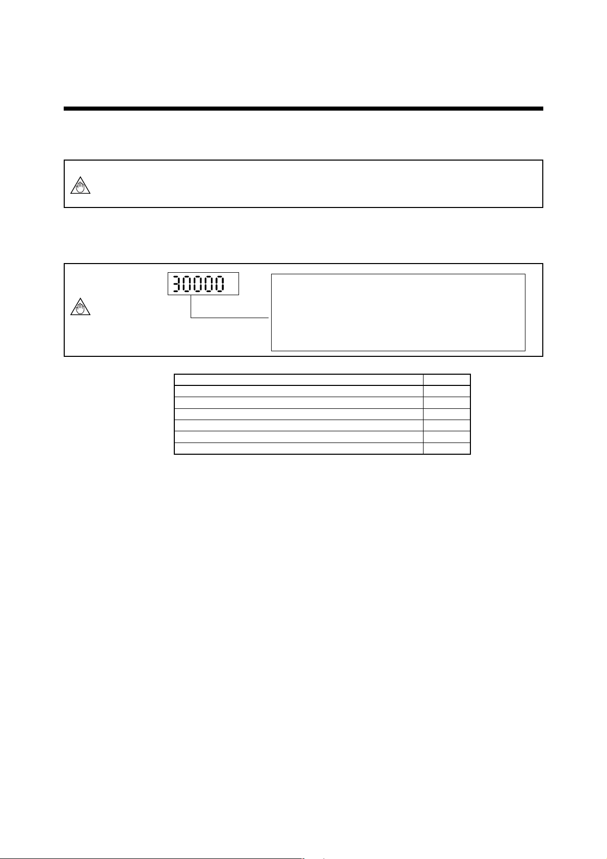
4.2.6 Indicator Error Mode
In the event the glass is stained or objects are placed near or on the glass, the switches
can be activated due to the infrared deflection. This will cause the "Password Input
Mode" to be displayed frequently and make the normal display mode unavailable. The
following comments relate to this possible occurrence.
*When the front glass of case is stained, please wipe out the glass by soft and dry
cloth.
*In case that each key keeps touching for more 120 sec. and it is continued, the
Password Input Mode is not available to enter.
*In case all keys are “OFF” for more 3 sec. , this mode is cancelled.
*This condition (the above-mentioned) is not an alarm, but the followings are shown
on LCD to indicate this condition.
(4 to 20 mA Output , Status Output , Flow Rate Indication Value and Self-check
Function work normally.)
*When these errors are raised, the display indicates alternately as follows.
4. BASIC OPERATING PROCEDURES
IMPORTANT
<< Flow Rate is indicated for 4 sec.
%
<< Warning is indicated for 2 sec.
In case of the front cover is loosened, "dSPErr" may occur, so please make sure the
cover is always fastened tightly.
4-8
IM 1E10B0-01E
Page 29
5. FUNCTION AND DATA SETTINGS
5. FUNCTION AND DATA SETTINGS
A Magnetic flowmeter calculates volume flow rate from a minute voltage that corresponds to the flow velocity of a fluid an outputs as a 4 to 20mA signal.
The three parameters must be set to obtain a correct signal.
NOTE
NOTE
Nominal size, flow span and meter factor must be set.
In these three factors, Nominal size (unit:mm) and meter factor are set before shipment.
This chapter explaines how to set flow span, other functions and data settings.
Please set data correctly.
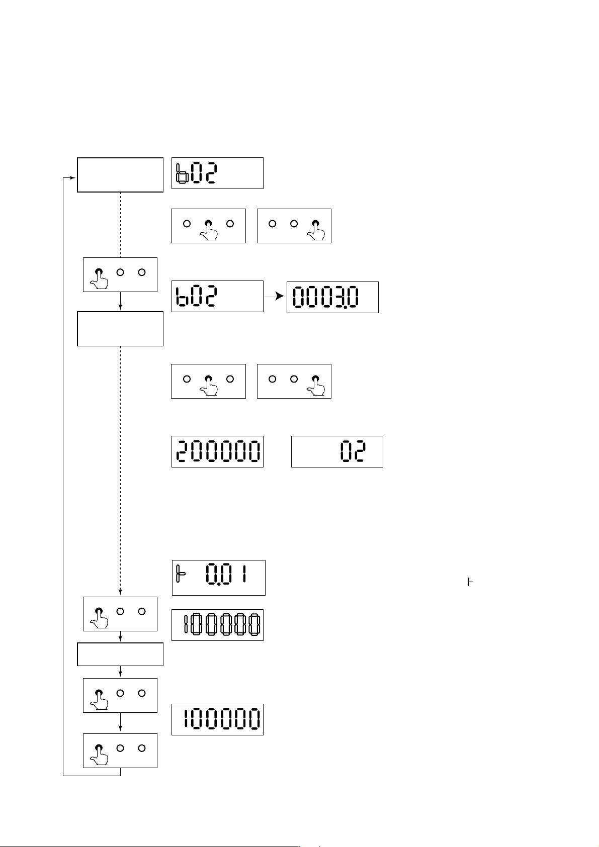
• you cannot set the leftmost digit of display to numeric value
greater than "4". If the leftmost digit of the span must be "4| or
more, set the numeric value beginning from the digit second
from the left on the display (the fourth digit).
• If the leftmost digit of the display is set to "3", the digits to its
right can be set to "0" only, regardless of the decimal point
position
Basic Key Operations
How to change the display into the setting mode?
How to move the cursor on the display during parameter setting?
How to change the display into the data changing mode?
How to move the cursor in the data changing mode?
How to change the data?
Finally, How to input the set data?
5.1 Setting Flow Span
(1) Determing the Flow Span
The flow rate span is the instantaneous flow rate value at which the output current is to
be 20mA.
Please determine the span under considering the followings.
• Please set the maximum flow rate at the most variable flow rate line.
If the flow rate of the fluid exceeds the flow rate span value, the flow rate that
exceeds this value (20mA or more) is not output and the flowmeter will not display
the correct flow rate. (108% or more can't be output)
• In a line where the flow rate is comparatively stable, set a value that is 1.5 to 2.0
times larger than the normal flow rate.
•Please set a value that will correspond to a flow velocity of 0.3 to 10m/s.
Please comfirm the flow velocity by sizing data or parameter No. “b13”.
(Parameter No. “b13” indicates corresponding flow velocity to set span)
• The basic input value for display is flow span value. It is recommended that the
accuracy of the first digit is in a 0.05 to 0.1% in case inputting the flow rate span
value.
For example, 30m3/h should be set as 30.00m3/h.
• In a span setting, the maximum value that can set is “30000” except any relation
with decimal position.
Key OperationItem
SET
SHIFT
SET
SHIFT
INC
SET (Twice)
5-1
IM 1E10B0-01E
Page 30
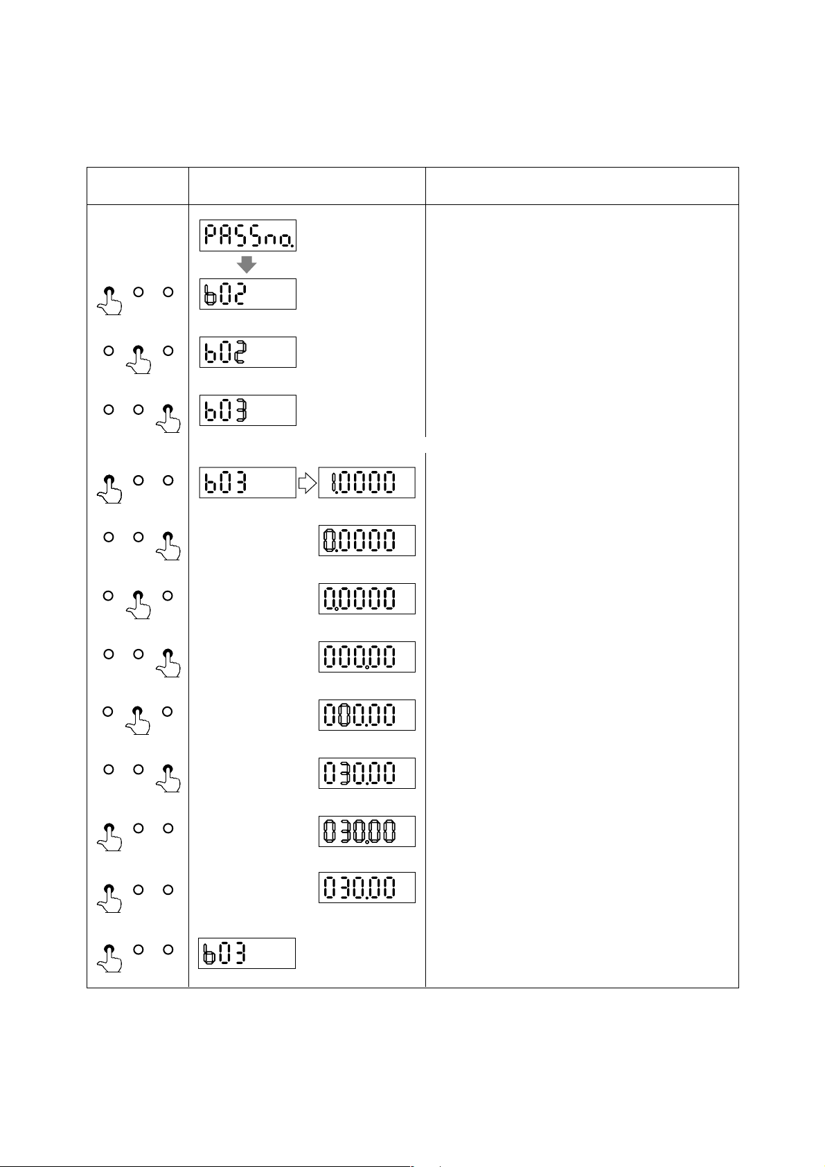
5. FUNCTION AND DATA SETTINGS
(2) Span Settings by Infrared Switches on the Converter (Example: Flow Span 30.00m3/h)
● Span Value Setting
Switch Operation Display Description
(See 4.2.1 The initial
procedure to change the
display)
SET SHIFT INC
Change into the password input mode through the setting mode.
(Please refer to Chapter 4 “BASIC OPERATION
PROCEDURES.”)
SET SHIFT INC
SET SHIFT INC
SET SHIFT INC
SET SHIFT INC
SET SHIFT INC
SET SHIFT INC
SET SHIFT INC
SET SHIFT INC
By touching the SHIFT and INC key, set the parameter
No. “b03”.
Defalt is set as 1.0000. Please change this into 0030.0.
By touching the SHIFT key, change into the data changing
mode.
By touching the INC key, change into “0”.
By touching SHIFT key, the cursor moves to the decimal point.
The decimal point on the cursor can be moved by touching the
INC key.
And by touching SHIFT key, blinking part moves to the right.
SET SHIFT INC
SET SHIFT INC
SET SHIFT INC
SET SHIFT INC
(Setting is now completed)
By touching INC key, change into “3”.
By touching SET key, whole Display is blinking.
And by touching the SET key again, the data is completed.
5-2
IM 1E10B0-01E
Page 31

5. FUNCTION AND DATA SETTINGS
● Setting Volume Measurement (m3) and Time Unit (/h)
Switch Operation Display Description
SET SHIFT INC
SET SHIFT INC
SET SHIFT INC
SET SHIFT INC
SET SHIFT INC
SET SHIFT INC
SET SHIFT INC
(Select m3)
Defalt : 12
Change into the number changing mode through the setting
mode.
By touching the SHIFT and INC key, please set the parameter
No.“b04”.
Volume Unit
Code
km3(103⫻m3)
And by touching the SET key,
change into the data changing mode.
By touching the INC key, set the “01”
(equivalent as m3)
By touching the SET key,
whole display is blinking.
And touching the SET key again,
the data is completed.
00
01
02
03
04
05
06
07
08
09
10
11
12
13
3
m
L(liter)
cm3(10-2⫻m)
M gal
k gal
gal
m gal
k bbl
bbl
m bbl
u bbl
m
ft.
And by touching the SET key, the data is completed and back
into the number changing mode.
3
(Select /h)
SET SHIFT INC
SET SHIFT INC
SET SHIFT INC
SET SHIFT INC
SET SHIFT INC
SET SHIFT INC
SET SHIFT INC
Defalt : 03
(Setting is now completed)
By touching the SHIFT and INC key, set the parameter
No. “b05”.
By touching the SET key, change into the data changing mode.
By touching the INC key, set the
Time Unit
“01” (equivalent as /h)
By touching the SET key,
whole display is blinking.
Code
00
01
02
03
/d
/h
/m
/s
And touoching the SET key again, the data is completed.
* If keys that except SET key are touched during display is
blinking, input data is not completed and back to former data.
5-3
IM 1E10B0-01E
Page 32

5. FUNCTION AND DATA SETTINGS
5.2 Power Frequency (For DC Power Supply Version only)
IMPORTANT
In case of DC power supply version, setting power frequency is required.
Display Description
Set the value in areas where the frequency differs in
“b12”.
Default: 50.00Hz
5.3 Other Functions and Settings
5.3.1 Pulse Output
PLS/ALM+, PLS/ALM– terminals are for common use with pulse, alarm and other
NOTE
(1) Pluse Output Overview
status output functions. Therefore, in case this function is used, other functions are not
available to use.
• By setting a pulse weight, a scaled pulse is transmitted to external counters or
measuring instruments.
Pulse Output Overview
Output Specifications
Connecting
Terminals
Pulse Width
Output Rate
* Please refer to “3.4.5 Output Connection to External Instruments” for information how to connect external
instruments.
(2) Procedures for Setting Pulse Output
Example setting: 10L output per pulse in a flow rate span of m3/h
ContentItem
Transistor contact output (contact capacity is 30V DC, 200mA)
PLS/ALM+, PLS/ALM– When using these for pulse output, alarm output or
status output are not available as the terminals are
used commonly.
Selection: DUTY50%, 0.5, 1, 20, 33, 50, 100ms
Min. 0.0001p/s, Max. 1000p/s
Display Description
Pulse output can be set in parameter No. “b10” and
selected “00” (Pulse output).
Default: 00
ContentCode
00
Pulse output
01
Alarm output
02
Forward / reverse flow measurement
03
Automatic two range switching
04
Alarm output at low flow limit
05
Totalization switch
5-4
IM 1E10B0-01E
Page 33

5. FUNCTION AND DATA SETTINGS
■■
Display Description
After setting the number changing mode, the unit of pulse
weight is set in parameter No. “F01”.
Default : 06
Volume unit in that for the flow rate span × 10
00
Volume unit in that for the flow rate span × 10
01
Volume unit in that for the flow rate span × 10
02
Volume unit in that for the flow rate span × 1
03
Volume unit in that for the flow rate span × 10
04
Volume unit in that for the flow rate span × 10
05
Number of pulses output per second at 100%
06
output
Volume UnitCode
-9
-6
-3
3
6
When Pulses are to be output per same liter with the flow
rate span of
m3/h, select “02” since L = 10-3 × m
Set the pulse weight “10” in parameter No. “F02”.
Default : 0
Set the low cut range nearby 0% in parameter No.
“F03”.
Default: (3%)
Setting Range: 0 to 100% (of span)
The pulse width can be set in parameter No. “F04”.
Pulse WidthCode
Default: 00
00
50%DUTY (Max. 1000p/s Min. 0.0001p/s)
01
0.5ms (Max. 1000p/s Min. 0.0001p/s)
02
1ms (Max. 500p/s Min. 0.0001p/s)
03
20ms (Max. 25p/s Min. 0.0001p/s)
04
33ms (Max. 15p/s Min. 0.0001p/s)
05
50ms (Max. 10p/s Min. 0.0001p/s)
06
100ms (Max. 5p/s Min. 0.0001p/s)
Normally, these are all required settings. The following settings are made depending on the applications
that are used.
3
(Flow rate value after damping)
Default: 01
Default: 00
5-5
The pulse output calculation can be set in parameter No.
“n01” by selecting flow rate or flow rate value after
damping.
In case the pulse output transistor should be OFF
ACTIVE, please change the parameter No. in “n02” to
“01”.
IM 1E10B0-01E
Page 34

5.3.2 Display of Internal Totalization Values
■■
• By setting a weight per a pulse, flow rate totalized value is shown on the display of
the converter.
(1) Setting Totalization Pulse Weight
Example: To output 10 L per pulse in flow rate span of m3/h.
Display Description
5. FUNCTION AND DATA SETTINGS
Set the pulse weight unit in parameter No. “E01”.
Defalt : 06
Default : 3%
(Damped flow rate value)
Default : 01
Volume unit in that for the flow rate span × 10
00
Volume unit in that for the flow rate span × 10
01
Volume unit in that for the flow rate span × 10
02
Volume unit in that for the flow rate span × 1
03
Volume unit in that for the flow rate span × 10
04
Volume unit in that for the flow rate span × 10
05
Number of pulses output per second at 100%
06
output
When Pulses are to be output per same liter with the flow
Volume UnitCode
rate span of
m3/h, select “02” since L = 10-3 × m
-9
-6
-3
3
6
3
Set the pulse weight “10(l)” in parameter No. “E02”.
Set the low cut range nearby 0% in parameter No.
“E03”.
Setting Range: 0 to 100% (of span)
The flow rate totalized value calculation can be set in
parameter No. “n01” by selecting “NO DAMPING” or
“DAMPING”.
5-6
IM 1E10B0-01E
Page 35

5.3.3 Resetting for Totalization Display
(1) Presetting for Forward Totalization Display
• E04, E05 are used for reset or preset the totalization values of the display.
Display Description
Default: 00 (disabled)
Default: 0
5. FUNCTION AND DATA SETTINGS
The totalization value presetting enable can be selected at
parameter No. “E04”.
ContentCode
00
Totalization preset inhibit
01
Totalization preset enable
The totalization value presetting enable is selected at
parameter number “E05”. The initial value is “0”, if it is
no setting, the function is zero setting.
SET SHIFT INC
(Twice)
(2) Zero-resetting for Reverse Toralization Display
Display Description
Default: 00 (disabled)
SET SHIFT INC
(Twice)
During the A30 :TOTAL (totalization value of flow rate)
is shown, the totalization value display is becoming the
value that is set at parameter number “E05”, by touching
SET key twice.
The totalization value presetting enable can be selected at
parameter No. “E04”.
00
01
During the A31 :REV.TOTAL (totalization value of
reverse flow rate) is shown, the totalization value display
is becoming zero, by touching SET key twice.
ContentCode
Totalization preset inhibit
Totalization preset enable
5-7
IM 1E10B0-01E
Page 36

5.3.4 Damping Time Constant
• The time constant can be changed by setting the parameter No. “b02” to suppress a
fluctuation or change a response time.
• The time constant influences to flow rate, pulse output and internal totalization.
However, in case “00” is selected in parameter No. “n01”, the pulse output and
internal totalization are not influenced by it.
Display Description
Default: 3(sec).
5.3.5 Current Output during Alarm Occurrence
• The current output and display values during alarming can be selected in advance.
Display Description
Default: 03
5. FUNCTION AND DATA SETTINGS
The time constant can be set in parameter No. “02”.
Setting Range: 0.5 to 200.0 sec.
The current output value during alarming can be set in
parameter No. “b11”.
Code
00
01
02
03
Content
2.4mA or less
4.0mA
HOLD
21.6mA or more
5.3.6 Reversing Flow Direction
• The flow direction is set to “FORWARD” at the factory. This function enables to
set flow direction from “FORWARD” to “REVERSE”.
Display Description
The flow derection can be set in parameter No. “b14”.
Default: 00
Code
00
01
Content
Forward direction
Reverse direction to flow arrow
5-8
IM 1E10B0-01E
Page 37

5.3.7 Limiting Current Output
(1) 4 to 20mA Low Cut Output (Current output nearby 0% range)
• This function makes it possible to reduce fluctuations in the 0% region to reduce it to
0%.
Display Description
5.6mA(10%)
5. FUNCTION AND DATA SETTINGS
Output
(2) 4 to 20mA Low Limit
(3) 4 to 20mA High Limit
Default : 00
4mA
Setting range: 0 to 10% Default:0(%)
0.5%0.5%
Set value
Hysteresis:1% fixed
• This function limits the low end of the analog output.
• The default value is set at –20%, and –10% as reverse flow limit. Please set in case
other setting is required.
• 2.4mA or less output in alarming is also limited.
Display Description
Default : -20(%)
Setting Range: –20 to 100%
Default: –20%
5.6mA(10%)
Output
4mA
• This function limits the high end of the analog output.
• The default value is set at 120%, and please set in case other setting is required.
• 21.6mA or more output in alarming is also limited.
Display Description
Output
18.4mA (90%)
Default : 120(%)
4mA
Setting Range: 0 to 120%
Default: 120%
5-9
IM 1E10B0-01E
Page 38

5.3.8 Forward and Reverse Flow Measurement
• This function enables to measure forward and reverse flow rate without change the
detector direction.
• By setting reverse range, in case fluids flow to reverse direction the flowmeter
measures it as reverse direction range automatically. In this time, a status signal that
shows changing into the reverse direction is output.
• To set the internal totalizing function for forward direction can also show it for
reverse direction by parameter settings.
• PLS/ALM+, PLS/ALM– terminals are used for output connection.
PLS/ALM+, PLS/ALM– terminals are for common use with pulse, alarm and other
NOTE
status output functions. Therefore, in case this function is used, other functions are not
available to use.
Display Description
Default: 00
5. FUNCTION AND DATA SETTINGS
F and R flow rate measurement can be selected as “02” in
parameter No. “b10”.
Code
00
Pulse output
01
Alarm output
02
Forward / reverse flow measurement
03
Automatic two range switching
04
Alarm output at low flow limit
05
Totalization switch
Content
Default: 2%
Reverse direction span can be set in parameter No.
“b30”.
Flow rate unit is the same as forward direction span.
Futher reverse range span should be set in the same
number of places of decimals as forward range span.
Example: forward flow rate : 1.000 then revers flow rate
should be 4.000.
Hysteresis width at switching direction can be set in
parameter No. “b31”.
It is the rate (%) of the smaller span, either forward or
reverse span.
0%
Flow Rate
Hysteresis
Status output
Forward flow measurement: OFF
Reverse flow measurement: ON
When using reversed status (ON/OFF)
is required, it can be set in “N02 Output Mode”.
5-10
IM 1E10B0-01E
Page 39

5.3.9 Automatic Two Range Switching
•When an input exceeds 100% of the first range, the range is automatically transferred
to the second range and the status output changes state.
• PLS/ALM+, PLS/ALM– terminals are used for output connection.
PLS/ALM+, PLS/ALM– terminals are for common use with pulse, alarm and other
NOTE
status output functions. Therefore, in case this function is used, other functions are not
available to use.
Display Description
Default : 00
5. FUNCTION AND DATA SETTINGS
Automotic two range transfer can be selected “03” in
parameter No. “b10”.
Code
Pulse output
00
Alarm output
01
Forward / reverse flow measurement
02
Automatic two range switching
03
Alarm output at low flow limit
04
Totalization switch
05
Content
Default : 1.0000
Default: 10%
Forward second range can be set by calling up parameter
No. “b33”.
Setting restrictions: First range ≤ 2nd range.
Further second range span should be set in the same
number of places of decimals as first range span in
parameter No. “b03”.
Example: First range : 1.000 then second range should be
4.000
Hysteresis width at switching range can be set in
parameter No. “b34”.
It is the rate (%) of first range span.
Output
100%
0 %
1st range: OFF
2nd range: ON
Status Output ON
Hysteresis (%)
Status Output
2nd range1st range
Flow Rate
5-11
When using reversed status (ON/OFF)
is required, it can be set in “N02 Output Mode”.
IM 1E10B0-01E
Page 40

5.3.10 Alarm Output at Low Flow Limit (Flow Switch)
• In case flow rate decrease under set level, an status signal is output.
PLS/ALM+, PLS/ALM– terminals are for common use with pulse, alarm and other
NOTE
status output functions. Therefore, in case this function is used, other functions are not
available to use.
Display Description
Alarm output at low flow limits can be selected “04” in
parameter No. “b10”.
Defalt : 00
Defalt : -10(%)
Code
00
01
02
03
04
05
The Low Limit value can be set in parameter No. “b36”
as parcentage for 4 to 20 mA.
5. FUNCTION AND DATA SETTINGS
Content
Pulse output
Alarm output
Forward / reverse flow measurement
Automatic two range switching
Alarm output at low flow limit
Totalozation switch
Default : 5(%)
Hysteresis width is set in parameter No. “b37”.
Output
low flow
limits
value.
Status
Output
On
When using reversed status (ON/OFF)
is required, it can be set in “N02 Output Mode”.
Hysteresis
5-12
IM 1E10B0-01E
Page 41

5.3.11 Totalization Switch Output
• In case the Internal Totalization Value increase over set level, an alarm signal is
output.
PLS/ALM+, PLS/ALM– terminals are for common use with pulse, alarm and other
NOTE
status output functions. Therefore, in case this function is used, other functions are not
available to use.
Display Description
Default : 00
Default : 0
5. FUNCTION AND DATA SETTINGS
Totalization switch can be selected as “05” in parameter
No. “b10”.
Code
00
Pulse output
01
Alarm output
02
Forward / reverse flow measurement
03
Automatic two range switching
04
Alarm output at low flow limit
05
Totalization switch
Switch level can be selected by calling up parameter No.
“E06”.
Totalization
999999
Content
Setting value
10000
Status
Output
ON
When using reversed status (ON/OFF)
is required, it can be set in “N02 Output Mode”.
Input
5-13
IM 1E10B0-01E
Page 42

5.3.12 Alarm Output
• This function is for status output from PLS/ALM+, PLS/ALM– terminals, when an
PLS/ALM+, PLS/ALM– terminals are for common use with pulse, alarm and other
NOTE
status output functions.
Therefore, in case this function is used, other functions are not available to use.
•All of the alarms are able to output except empty pipe detection function that can be
• The status goes from close to open (OFF) during alarming.
alarm occurs.
selected in parameter No. “n07” as out of selection.
Display Description
The alarm output can be selected “01” in parameter No.
“b10” and P+, P– terminals are only for alarm output.
Default: 00
Code
00
01
02
03
04
05
Content
Pulse output
Alarm output
Forward / reverse flow measurement
Automatic two range switching
Alarm output at low flow limit
Totalization switch
5. FUNCTION AND DATA SETTINGS
* Item “n” can be called up in setting “55” in parameter No. “L02”.
5.3.13 Data Settings Enable / Inhibit
• This function can inhibit to change all data except parameter No. “ L01”.
However, auto zero adjustment function can work, if it has been set in parameter No.
“C01”.
And the preset totalization value function also can work, if it has been set in parameter No. “E04”.
Displayed Description
Default: 01
Default: 01
The empty pipe output selection can be set in parameter
No. “n07”.
Code
00
01
The data settings inhibit item can be set “00” in
parameter No. “L01”.
Code
00
01
Content
ALARM
NO ALARM
Content
INHIBIT
ENABLE
5-14
IM 1E10B0-01E
Page 43

5.3.14 Procedure of Selecting Special Application Items
• Only the special apprication (“n” items) shipped being unpublished.
In case the “n” items should be used, it can be set “55” in parameter No. “L02”.
Displayed Description
The “n” items can be set “55” in parameter No. “L02”.
5. FUNCTION AND DATA SETTINGS
5.3.15 Rate Limit
Default: 00
Code
00
55
Content
Accessible up to L parameters.
Accessible up to n parameters.
• This function is used to remove noise that cannot be removed by increasing the
damping time constant.
•In case unexpected noise from step signal or slurry is entered, a basis is set to
recognize that signal is flow rate or noise.
The recoginition depends on rate limit value (upper and lower limit) and dead time
(sampling time).
• Determination of rate limit value and dead time.
Rate limit value:
Determine the level to reduce output
fluctuation.
For example, reducing 2% or more
fluctuation by setting as 2% to
reduce.
2%
2%
Dead time T0:
Please determine the dead time
depending on ouput fluctuation width.
In case of noise of which is longer
than the dead time, please set the
dead time longer.
T
0
T
0
• Signal processing procedures:
The function sets a certain upper and lower limit (rate limit value) for first order
delay response values of flow rate data obtained in a previous sampling. If currently
sampled flow rate data exceeds or goes below the limit is regarded as current flow
rate value. Signals whose protruding portions show the same trends during a certain
number of sampling times (dead time) are identified as flow rate signals.
5-15
IM 1E10B0-01E
Page 44

Example 1: Step Input
5. FUNCTION AND DATA SETTINGS
10%
1%
Dead time: 3 sec. (Sampling 80 ms × 18 times)
Step Signal
(1)
Flow rate value
after rate limiting
(2)
9
(3)
18
(4)
Flow rate value after
damping
Input: 0 to 10%
Damping time constant: 3 sec.
Dead time: 3 sec.
Rate limit value: 1%
63.2%
(1) Shows 1% response cause of excessive signal beyond the rate limit. However, actual
output is under damping that described by a solid line.
(2) Shows the flow rate signal (1%) of just after damping calculation (1) and rate limit
value.
(3) This signal is recognized as a flow rate signal since it does not return to within the
rate limit value within the dead time.
(4) The output signal follows the damping curve and tracks the step signal.
Example 2: Slurry Noise
Slurry Noise
Flow rate value after
rate limiting
+1%
Input: 0 to 10%
Damping time constant: 1 sec.
Dead time : 1 sec.
Rate limit value: 1%
–1%
The left figure shows that the slurry
noise is not a flow rate signal.
Flow rate value after rate limiting and damping.
Dead time: 1 sec.
Displayed Description
The rate limit value can be set in parameter No. “n03”.
Setting Range: 0 to 10%
Default: 5(%)
The dead time can be set in parameter No. “n04”.
Setting Range: 0 to 15 sec.
Default: 0(%)
(Rate limit function halt at 0)
5-16
IM 1E10B0-01E
Page 45

6. OPERATION VIA BRAIN TERMINAL
6. OPERATION VIA BRAIN TERMINAL (BT200)
Products come equipped with a BRAIN communication function communicate with
dedicated BRAIN terminals (BT200) or computer system. In the BRAIN Series communications system, modulated signal is superimposed onto the 4 to 20 mA DC analog
signal for data transmission. Since the modulated wave is an AC signal superimposed on
the analog signal will cause no error in the DC component of the analog signal. In this
way, monitoring can be performed via communications while the ADMAG SE is online.
This section describes the operation procedures using BRAIN terminal. For details on
the functions of the ADMAG SE, see Chapter 5, “Function and Data Settings.” And
also, see the “BT200 Instruction Manual” (IM 1C0A11-01E) for more detailed information.
6.1 BT200 Connections
(1) Connecting BT200 to 4 to 20 mA DC Transfer Line
The communication signal of the ADMAG SE with BRAIN communication function is
superimposed onto the 4 to 20 mA DC analog signal to be transferred.
Intermediate
terminals
+
CUR
–
CUR
Figure 6.1 Interconnection Diagram
4 to 20mA DC signal
transfer line
Control room
Receiver
Terminal board
Receiver resistance,
250Ω to 600Ω
BT200BT200 BT200
6-1
IM 1E10B0-01E
Page 46

6.2 BT200 Keypad Layout
Figure 6.2 shows the key pad layout of BT200.
6. OPERATION VIA BRAIN TERMINAL
LCD
8 lines with 21 characters each
Function keys
Executes the commands displayed at the bottom
of the screen.
Power
ON/OFF key
Entry cursor
(Inverse video)
Message
Menu panel Parameter panel
MENU BATTERY
A: DISPLAY
B: SET
C: ADJUST
D: DISP SEL
E: TOTAL SET
F: PULSE SET
HOME SET ADJ ESC
PARAM
A10:FLOW RATE(%)
0.6%
A20:FLOW RATE
0.06 m3/h
A30:TOTAL
0
DATA DIAG PRNT ESC
Arrow keys
• Selects an item.
• Moves the cursor.
• Page feeding.
ENTER key
• Goes to the selected item.
• Sets the entry data to the object
communication instrument.
• Executes the BT200 functions.
Alphanumeric keys
• Enters a number.
• Enters letters when pressed together with the
shift key.
SHIFT keys
Major parameters items
A maximum of six items are displayed.
Figure 6.2 Key Layout and Functions
Function commands
6-2
Parameter data
A maximum of three items
are displayed.
IM 1E10B0-01E
Page 47

6.3 BT200 Key Functions
(1) Entry of Alphanumeric Characters
Numbers, codes and letters can be entered in combinations of the alphanumeric keys and
the SHIFT key.
• Entry of numbers, codes and a space (0 to 9, ., -, )
Entering of them is possible by using the alphanumeric keys.
Example of Entry Key Operation
6. OPERATION VIA BRAIN TERMINAL
[
–4.3
1 –0.3
XW
–
NM
1
HG
4
ZY
SPACE
VU
.
XW
–
RQ
3
TS
0
VU RQ
.
• Entry of letters
Press an alphanumeric key while one
BA
7
of the SHIFT keys is pressed and the
letter on the same side of the key as
the SHIFT key that is pressed can be
entered. Press the SHIFT key each
time when entering a letter.
Example of Entry Key Operation
WIC
J. B
■
SHIFT
–
■
5
The letter on the left
side of the
alphanumeric key is
entered.
■
XW
SHIFTSHIFT
JI
■
SHIFT
VU
.
SHIFT
The letter on the
right side of the
alphanumeric key is
entered.
■
JI
5
SHIFT
■
■
SHIFT
BA
7
• Selection of capital/small letters
Capital and small letters can be selected alternately by pressing the function key [F2]
(CAPS).
Entry of capital letters
CODE CAPS CLR ESC
Entry of small letters
CODE caps CLR ESC
3
DC
8
F2
F1 F3 F4 F1 F2 F3 F4
• Entry of codes
Codes can be entered by pressing the function key [F1] (CODE). Every time [F1]
CODE is pressed, the codes are displayed at the cursor position in the order shown
below.
/ . - , + * ) ( ' & % $ ” !
To enter characters after the above codes, move the cursor using the [>] key before
entry.
Example of Entry Key Operation
l/m
F2 F1
■
SHIFT
LW
6
6-3
>
■
SHIFT
( m )( / )( l )(Small letter)
IM 1E10B0-01E
XW
1
Page 48

(2) Function Keys
6. OPERATION VIA BRAIN TERMINAL
The functions of the function keys vary with the commands being displayed on the
display panel.
MENU
A: DISPLAY
B: SET
C: ADJUST
D: DISP SEL
E: TOTAL SET
F: PULSE SET
HOME SET ADJ ESC
F2F1 F3 F4
Function keys
6.4 Displaying Flow Rate Data
Flow rate data can be displayed on the BT200 panel according to the following procedure.
Command
CAPS/caps
CODE
COPY*
FEED*
HOME
PARM
PON/POFF*
PRNT*
STOP*
*The command is available only for BT200-P00.
Calls up the zero-adjustment menu.
ADJ
Changes the capital/small letter mode.
Clears entered data/deletes all data.
CLR
See the above “Entry of code.”
Prints parameters on the panel.
Updates parameter data.
DAT A
Deletes one character.
DEL
Calls up the self-check panel.
DIAG
Returns to the previous panel.
ESC
Paper feed.
Calls up the home menu (A:DISPLAY).
Prints all parameters of the menus.
LIST*
Setting stop/re-setting. Returns to the previous panel.
NO
Goes to the next panel.
OK
Parameter number setting mode.
Printer output of data whose setting was changed Mode on/off.
Changes to the print mode.
Calls up the setting menu. (B:SETTING)
SET
Returns to the slot selection panel.
SLOT
Starts print out.
GO*
Stops printing.
Calls up the utility panel.
UTIL
Description
Display Description
ON/OFF
--WELCOME-BRAIN TERMINAL
ID:BT200
Check cable connection
and press the ENT key.
UTIL FEED
ENTER
PARAMETER
01:MODEL
SE14-A00
02:TAG NO.
03:SELF CHECK
GOOD
or
ENTER
F4
MENU
A:DISPLAY
B:SET
C:ADJUST
D:DISP SEL
E:TOTAL SET
F:PULSE SET
HOME SET ADJ ESC
PARAM
A10:FLOW RATE(%)
0.6 %
A20:FLOW RATE
0.06 m3/h
A30:TOTAL
0
DATA PRNTDIAG ESC
Inverse video bar
ENTER
Turn the power on and the panel as shown on the left appears after
“Please wait...” is displayed for a few seconds.
Pressing the ENTER key causes the initial data panel as shown on
the left to be displayed.
The tag number specified upon ordering has been entered.
OK
Pressing the F4 key [OK] or the ENTER key causes the menu panel
as shown on the left to be displayed.
Select “A:DISPLAY” on the menu screen with the inverse video bar
and press the ENTER key to make the flow data panel appear.
● A maximum of three data items can be displayed on one panel.
● Data are updated at an interval of 5 seconds.
● The arrow keys, [∧], [∨], [<] or [>], are used for page feeding or
item selection.
6-4
IM 1E10B0-01E
Page 49

6.5 Setting Parameters
The three parameters must be set to obtain a correct signal.
NOTE
6.5.1 Setting Flow Span
Nominal size, flow span and meter factor must be set.
In these three factors, nominal size (unit:mm) and meter factor are set before shipment.
Example: Flow span 30.0 m3/h
Display Description
ON/OFF
--WELCOME-BRAIN TERMINAL
ID:BT200
CHECK CABLE CONNECTION
AND PRESS THE ENT KEY.
UTIL FEED
ENTER
PARAM
01:MODEL
SE14-A00
02:TAG NO.
03:SELF CHECK
GOOD
ENTER
MENU
A:DISPLAY
B:SET
C:ADJUST
D:DISP SEL
E:TOTAL SET
F:PULSE SET
HOME SET ADJ ESC
ENTER
PARAM
B01:TAG NO
B02:DAMPING
3.0 s
B03:FLOW SPAN
1.00 m/s
DATA DIAG ESC
ENTER
SET
B03:FLOW SPAN
1.0000 m/s
0
6. OPERATION VIA BRAIN TERMINAL
Turn the power on and the panel as shown on the left appears after
“Please wait...” is displayed for a few seconds.
Pressing the ENTER key causes the initial data panel to be displayed.
OK
or
Pressing the F4 key or ENTER key causes the menu panel to be
F4
displayed.
Use the arrow key to select “B:SET” with the arrow key and press
the ENTER key.
Then, the parameter panel is displayed.
Select “B03:FLOW SPAN” using the arrow key and press ENTER
key to call up the following data setup panel.
Press ENTER key on the parameter panel to display the data setup
panel as shown on the left.
(If the security panel appears, enter the security code.*)
DEL CLR ESC
Enter “30.0” using the alphanumeric keys. Default:1.0000(m/s)
(This “B03: FLOW SPAN” is for entering the value, not units.)
×2
Press ENTER key twice at an interval of a few seconds.
SET
B03:FLOW SPAN
1.00 m/s
30.0
DEL ESC
ENTER
“30.0”
* For entry of the security code, see IM1C0A11-01E.
6-5
IM 1E10B0-01E
Page 50

6. OPERATION VIA BRAIN TERMINAL
Display Description
SET
B03:FLOW SPAN
30.0 m/s
NO OK
F4
PARAM
B01: TAG NO
B02: DAMPING
3.0 S
B03: FLOW SPAN
30.0 m/s
DATA DIAG ESC
PARAM
B02: DAMPING
3.0 S
B03: FLOW SPAN
30.0 m/s
B04: FLOW UNIT
m
DIAGDATA ESC
ENTER
SET
B04:FLOW UNIT
m
< km3 >
< m3 >
< l >
< cm3 >
ESC
ENTER
SET
B04:FLOW UNIT
m3
The display as shown on the left appears.
If the data is correct, press F4 key [OK].
The parameter panel is displayed again.
Select “B04:FLOW UNIT” by feeding the page with the arrow key.
Press ENTER key to display the data setup panel.
3
3
* km
cm3 : (10
Select “m
interval of a few seconds. Default:m
×2
(If the security panel appears, enter the security code.*)
3
: 10
X
m
-2
3
X
m)
3
” with the arrow key and press ENTER key twice at an
NO OK
F4
PARAM
B02: DAMPING
3.0 S
B03: FLOW SPAN
30.0 m3/s
B04: FLOW UNIT
m3
DATA DIAG ESC
If the data is correct, press the F4 key [OK].
The parameter panel appears again.
Select “B05:TIME UNIT” by feeding the page with the arrow key.
PARAM
B03: FLOW SPAN
30.0 m3/s
B04: FLOW UNIT
m3
B05: TIME UNIT
/s
DIAGDATA ESC
ENTER
Press the ENTER key to call up the data setup panel.
* For entry of the security code, see IM1C0A11-01E.
6-6
IM 1E10B0-01E
Page 51

6. OPERATION VIA BRAIN TERMINAL
Display Description
SET
B05:TIME UNIT
/s
< /s >
< /d >
< /h >
< /m >
ESC
ENTER
SET
B05:TIME UNIT
/h
NO OK
F4
PARAM
B03:FLOW SPAN
30.0 m3/h
B04:FLOW UNIT
m3
B05:TIME UNIT
/h
HOME SET ADJ ESC
Select “/h” with the arrow key and press ENTER key twice at an
interval of a few seconds. Default:s
×2
If the data is correct, press the F4 key [OK].
The parameter panel appears again.
The setting is completed.
6.5.2 Power Frequency (For DC version only)
IMPORTANT
In case of DC power supply version, setting power frequency is required.
Display Description
PARAM
B10: OUTPUT FUNC
PULSE OUT
B11: 4-20 ALM OUT
21.6mA OR MORE
B12: POWER FREQ
50.00Hz
DATA DIAG ESC
Set the value in areas where the frequency differs in “B12:POWER
FREQ”.
Default: 50.00Hz
6.6 Other Functions
Please set other needed parameters. For detail on the functions, see Chapter 5, "Functions and Settings" except "User-Defined Units" function. For "User-Defined Units"
function, see 6.6.1 below.
6.6.1 User-Defined Units
This function displays the instantaneous flow rate indicated in “A20 FLOW RATE” in
user-defined units.
(1) User-Defined Unit for Instantaneous Flow Rate
Example 1:Displaying the flow rate of a fluid (its specific gravity is 2) in weight (kg)
in a flow rate span of 10 m3/h. When the flow rate is 100%, 20,000 kg/h is
displayed.
6-7
IM 1E10B0-01E
Page 52

6. OPERATION VIA BRAIN TERMINAL
Display Description
PARAM
D02:FL USER SEL
PROVIDED
D03:FL USER SPAN
20000.0
D10:FL USER UNIT
kg/h
DATA DIAG ESC
PARAM
A10:FLOW RATE(%)
100.0 %
A20:FLOW RATE
20000.0 kg/h
A30:TOTAL
0
DIAGDATA
PRNT
(2) User-Defined Unit for Totalization Value
User-defined unit can be added to the totalization display in “A30 TOTAL”
Display Description
PARAM
E04:TOTAL SET
INHIBIT
E05:TL SET VALUE
0
E10:TL USER UNIT
kg
DATA DIAG ESC
ESC
Select “PROVIDED” in “D02:FL USER SEL.”
Default:NOT PROVIDED
In “D03:FL USER SPAN” set the value of 100% flow rate to be
displayed in “A20:FLOW RATE” The user-defined unit is set in
“D10:FL USER UNIT” Default:100.0
Set the user-defined unit in “D10:FL USER UNIT”
The instantaneous flow rate in user-defined unit can be displayed in
“A20:FLOW RATE”
Set the user-defined unit in “E10:TL USER UNIT”
PARAM
A10:FLOW RATE(%)
100.0 %
A20:FLOW RATE
20000.0 kg/h
A30:TOTAL
40000kg
DIAGDATA
ESC
6.7 Other Important Points
(1) The automatic power-off function turns the BT200 off automatically with no key
access for about 5 minutes or more. However, this function does not operate when
the BT200 is displaying “A10:FLOW RATE (%)” or “A20:FLOW RATE”
(2) When “A10:FLOW RATE (%)” or “A20:FLOW RATE” is displayed, the data are
updated every 5 seconds.
(3) UPLOAD/DOWNLOAD functions which can copy the setting date between
ADMAG SE and BT200 are provided. (For details, see the “BT200 Instruction
Manual IM 1C0A11-01E.”)
Parameters that can be copied are as follows:
B02 DAMPING, B03 FLOW SPAN, B04 FLOW UNIT, B05 TIME UNIT,
B06 SIZE UNIT, B07 NOMINAL SIZE, B10 OUTPUT FUNC, B11 4-20 ALM OUT,
D01 DISP SELECT, D02 FL USER SEL, D03 FL USER SPAN,
D10 FL USER UNIT, E01 TOTAL UNIT, E02 TOTAL SCALE,
E03 TOTAL LOWCUT, E04 TOTAL SET, E05 TL SET VALUE,
E10 TL USER UNIT, F01 PULSE UNIT, F02 PULSE SCALE,
F03 PULSE LOWCUT, F04 PULSE WIDTH, G01 4-20 LOW CUT,
G02 4-20 LOW LMT, G03 4-20 H LMT
6-8
The totalization value in user-defined unit can be displayed in
“A30:TOTAL”
IM 1E10B0-01E
Page 53
7. OPERATION VIA HAR T
COMMUNICATOR
Matching of communicator DD and instrument DD
Before using model 275 HART communicator, check that the DD(Device Description)
CAUTION
installed in the communicator matches to that of instruments to set up. To check the DD
in the instrument or the HART communicator, follow the steps below. If the correct DD
is not installed in the communicator, you must upgrade the DD at the HART official
programming sites. For communication tools other than Model 275 HART communicator, contact vendors of each for upgrade information.
1. Checking the DD in the instrument
1) Connect the communicator to the instrument to set up.
2) Call “Device setup” and press [→].
3) Call “Review” and press [→].
4) By pressing [NEXT] or [PREV], find “Fld dev rev” to
show the DD of the instrument.
2. Checking the DD in Model 275 HART communicator.
1) Turn on the communicator alone.
2) Call “Utility” from main menu and press [→].
3) Call “Simulation” and press [→].
4) Select “YOKOGAWA” from manufacturers list by
pressing [↓] and press [→] .
5) Select the model name of the instrument (i.e. ADMAG
SE) by pressing [↓] and press [→] to show the DD of the communicator.
7. OPERATION VIA HART COMMUNICATOR
[Example]
ADMAG SE
Review
Fld dev rev
2
HELP PREV NEXT EXIT
“The instrument DD is Version 2”
[Example]
HART Communicator
Fld dev rev
1 Dev v1 , DD v2
2 Dev v2 , DD v1
“The communicator DD
supports Version 1 and 2.”
Version
1 and 2
7.1 Conditions of Communication Line
7.1.1 Interconnection between ADMAG SE and HART Communicator
The HART Communicator can interface with the ADMAG SE from the control room,
the ADMAG SE site, or any other wiring termination point in the loop, provided there is
a minimum load resistance of 230Ω between the connection and the receiving instrument. To communicate, it must be connected in parallel with the ADMAG SE, the
connections are non-polarized. Figure 7.1.1 illustrates the wiring connections for direct
interface at the ADMAG SE site. The HART Communicator can be used for remote
access from any terminal strip as well.
Control room
4 to 20 mA DC signal line
+
CUR
CUR
–
ADMAG SE
Communicator
Model 275
Relaying
terminals
HART
Figure 7.1.1 Interconnection Diagram
HART
Communicator
Model 275
Terminal board
Receiving instrument
load resistance:
HART
Communicator
Model 275
230Ω to 600Ω
7-1
IM 1E10B0-01E
Page 54

7.1.2 Communication Line Requirements
Specifications for Communication Line:
Load resistance: 230 to 600Ω (including cable resistance)
When multidrop mode, see Figure 7.1.2.
Minimum cable size: 24 AWG, (0.51 mm diameter)
Cable type: Single pair shielded or multiple pair with overall shield
Maximum twisted-pair length: 6,500 ft (2,000 m)
Maximum multiple twisted-pair length: 3,200 ft (1,000 m)
Use the follwing formula to determine cable length for a specific application;
7. OPERATION VIA HART COMMUNICATOR
(R×C)
6
(Cf+10,000)
C
65×10
L = –
where: L = length in feet or meters
R = resistance in ohms, current sense resistance
C = cable capacitance in pF/ft or pF/m
Cf = 50,000 pF
Load
Resistance
(Ω)
800
600
400
200
0
12 345678910 11 12 13 14 15
* Maximum Load Voltage: 600Ω × 25 mA = 15 V
230
571
500
444
400
363
333
Q’ty of connected field devices
307
Figure 7.1.2 Load Resistance and Quantity of Devices in Multidrop Mode
285
266
NOTE
The above graph shows the load resistance in case that each current output of all
connected transmitters is 4 mA.
7-2
IM 1E10B0-01E
Page 55

7. OPERATION VIA HART COMMUNICATOR
7.2 Basic Operation of the HART Communicator (Model 275)
7.2.1 Keys and Functions
Communication Cable
LCD (Liquid crystal display)
(21 characters×8 lines)
Function keys
Functions of the keys are indicated on the
display.
Power ON/OFF
Shift keys
Use to enter
alphabetic characters.
Move the inverse video bar (cursor) on the
display for selecting the desired item.
Hot key
Call up Hot Key Menu as follows:
1. Span
2. Enable Write
3. New Password
1. Change the display contents.
2. Move the position where a number or
character is to be entered.
Example
Pressing calls up the display
corresponding to the item pointed with the
cursor.
Pressing returns to the previous display.
(See 7.2.3 Calling up Menu Address.)
Alphanumeric keys
1.Enter numbers and characters.
2.Select the desired menu item with the
corresponding number. (See 7.2.4 Entering,
Setting and Sending Data)
Example
Pressing single key enters the number.
Pressing the key with shift key enters the
alphabetic character.
(Press) (ENTER)
To enter “7”,
To enter “C”,
ABC
7
ABC
7
‘7’
‘C’
Figure 7.2.1 HART Communicator
7-3
IM 1E10B0-01E
Page 56

7.2.2 Display
7. OPERATION VIA HART COMMUNICATOR
The HART Communicator automatically searches for ADMAG SE on the 4 to 20 mA
loop when it is turned on. When the HART Communicator is connected to the ADMAG
SE, it displays “Online” menu as shown below.
(If ADMAG SE is not found, the communicator displays the message “No Device
Found. Press OK....” Press the OK ‘F4’ function key and the main menu appears. Please
retry after confirming the connection with the ADMAG SE.)
Manufacturer’s Field Device
Type Code
<2>
<3>
<4>
<5>
Tag (8 Characters) <1>
appears when the voltage
level of the battery is low
The arrow mark corresponding
to the pressed key appears.
Inverse video bar
Function keys
Figure 7.2.2 Display
<1> appears and flashes during communication between the HART Communicator
and the ADMAG SE. At Burst mode*, appears.
<2> The current display menu title appears.
<3> Each item in menu of <2> appears.
<4> and/or appear when the items are scrolled out of the display.
<5> On any given menu, the label appearing above a function key indicates the function
of that key for the current menu.
Note: Refer to “7.3.4 Setting Parameters (6) Burst Mode”.
7.2.3 Calling Up Menu Addresses
7.3.3 Menu Tree shows the configuration of Online Menu which is needed for the
operation with HART Communicator. The desired item can be displayed with ease by
understanding the menu configuration.
When the HART Commnicator is connected to the ADMAG SE, “Online” menu will be
displayed after the power is turned on (See Figure 7.2.2). Call up the desired item as
follows:
7-4
IM 1E10B0-01E
Page 57

Key operation
7. OPERATION VIA HART COMMUNICATOR
There are two choices to select the desired menu item.
1. Use the or key to select the desired item, and then press the key.
2. Press the number key displayed for the desired item.
Device setup
PV
PV AO
Span
Display Operation
ADMAG SE : FI-100
1
Online
1 Device setup
2 PV
3 PV AO
4 Span
DEL SET ESC ENTER
• To return to the previous display, press the
key, EXIT (F4), ESC (F3) or
ABORT (F3).
Example: Call up the “Tag” to change the tag number.
Check where “Tag” is located in the menu configuration. Then, call up “Tag” on the
display according to the menu configuration.
process variables
Diag/Service
Basic setup
Detailed setup
Review
STU
or
1
:
Line size
PV Damp
Tag
ADMAG SE : FI-100
Tag
FI-100
FI-100
Descriptor
:
Display appears when the HART Communicator is turned
1
HELP DEL ESC ENTER
on.
Select “Device setup”.
ADMAG SE : FI-100
2
Device setup
1 Process variables
2 Diag/Service
3 Basic setup
4 Detailed setup
5 Review
DEL SAVE HOME ENTER
ADMAG SE : FI-100
3
Basic setup
1 PV Unit
2 Span
3 Nominal size
4 PV Damp
5 Tag
HELP SAVE HOME ENTER
ADMAG SE : FI-100
4
Tag
FI-100
FI-100
HELP DEL ESC ENTER
or
YZ /
3
or
MNO
5
×2
Select “Basic setup”.
Select “Tag”.
×4
The display for Tag setting appears.
(The default value of “Tag” is blank.)
7-5
IM 1E10B0-01E
Page 58

7.2.4 Entering, Setting and Sending Data
The data which are input with the keys are set in the HART Communicator by pressing
ENTER (F4). Then, by pressing SEND (F2), the data are sent to the ADMAG SE. Note
that the data are not set in the ADMAG SE if SEND (F2) is not pressed. All the data set
with the HART Communicator is held in memory unless power is turned off, so every
data can be sent to the ADMAG SE at one lot.
Operation
Entering data on the “Tag” setting display.
On alphabetic characters, only capital letters can be used for setting Tag No. with HART
Communicator.
Example: Set “FIC-1A”.
Call up “Tag” setting display.
1. Device setup 3. Basic setup 5. Tag
ADMAG SE :
1
Tag
7. OPERATION VIA HART COMMUNICATOR
5. Tag
HELP DEL ESC ENTER
On the setting display shown above, enter the data as follows:
Character to
Operation Display
be entered
DEF
8
I
C
: +
-
1
*
–
STU
1
A
GHI
9
ABC
7
ABC
7
FF
F I
F I C
F I C -
F I C - 1
F I C - 1 A
7-6
IM 1E10B0-01E
Page 59

Display Operation
ADMAG SE :
1
Tag
FIC-1A
HELP DEL ESC ENTER
F4
(ENTER)
7. OPERATION VIA HART COMMUNICATOR
Press ENTER (F4) to set the data in the HART Communicator
after entering the data.
ADMAG SE :
2
Basic setup
1 PV Unit
2 Span
3 Line size
4 PV Damp
5 Tag FIC-1A
HELP SEND HOME ENTER
ADMAG SE : FIC-1A
3
Basic setup
1 PV Unit
2 Span
3 Line size
4 PV Damp
5 Tag FIC-1A
HELP SAVE HOME ENTER
NOTE
F2
Press SEND (F2) to send the data to the ADMAG SE.
* is flashing during communication.
(SEND)
SEND SAVE
label changed to label, and the transmission
is completed.
Press HOME (F3), and return “Online Menu”.
Parameter setting on the indicator of ADMAG SE is prohibited during HART Communication.
7-7
IM 1E10B0-01E
Page 60

7.3 Parameters
7.3.1 Parameters Configuration
Parameters of HART Communicator is constructed hierarchically. The menu tree for
Online menu is shown in 7.3.3 Menu Tree.
See “Chapter 11. Parameter List” about the usage of each parameter. Note the differences between parameters on ADMAG SE display and those on HART Communicator.
The Online menu summary is shown below.
Table 7.3.1 Online Menu Summary
No. Display Item Contents
1
Device setup
2
3
4
7.3.2 Data Renewing
PV
PV AO
SPAN
7. OPERATION VIA HART COMMUNICATOR
Set parameters for ADMAG SE.
Display process value in engineering unit.
Display analog output in mA.
Display set span in engineering unit.
NOTE
There are two methods to load the data of ADMAG SE from/to HART Communicator,
periodic data renewing and discretionary data renewing.
(1) Periodic Data Renewing
The follwing data are renewed in 0.5 to 2 seconds cycle.
PV, PV AO, PV % rnge, Totl, Reverse total, Diff. total, Power freq, Velocity
check
(2) Discretionary Data Renewing
The following data can be loaded from/to ADMAG SE. Up load can be done with
SAVE (F2) on any online menu, and down load can be done on Saved Configuration
menu in Offline menu. (Refer to HART Communicator Manual.)
Descriptor, Message, Date, Tag, Span, Line size, Size unit, PV Damp, Base vol
unit, Base time unit, Disp select, Fl user sel, Fl user span, Total unit, Total scale,
Total low cut, Tl set value, Total set, Analog low cut, Analog low lmt, Analog hi
lmt, Analog alarm out, Output function, Pulse unit, Pulse scale, Pulse low cut,
Pulse width.
The changed data with HART Communicator is sent to ADMAG SE by pressing
SEND (F2) of HART Communicator.
7-8
IM 1E10B0-01E
Page 61

7.3.3 Menu Tree
7. OPERATION VIA HART COMMUNICATOR
Online Menu
1 Device setup
2 PV [r]
3 PV AO [r]
4 Span [r]
1 Process
variables
2 Diag/Service
3 Basic setup
1 PV [r]
2 Totl [w]
1 Test device
2 Loop test [sel]
3 Status out [sel]
1 PV Unit [sel]
2 Span [w]
3 Line size [w]
4 PV Damp [w]
5 Tag [w]
6 Descriptor [w]
7 Message [w]
8 Date [w]
1 Sensor
1 Status [r]
1 Test/Status
2 Auto zero [exe]
3 Zero tuning [sel]
4 Output trim
4mA, 20mA, Other, End
Normal, Closed(on), Open(off)
gal/min
L/min
Cum/h
m/s
ft/s
Spcl
1 PV [r]
2 Flow units
2 Self test [exe]
Inhibits, Enable
1 D/A trim
2 Scaled D/A trim
1 Base vol unit [sel]
Status group 1
Status group 2
Status group 3
k Cum, Cum, L,
Cucm, M gal, k gal,
gal, m gal, k bbl, bbl,
m bbl, u bbl, m, ft
4 Detailed
setup
2 Input
to be continued to next page
3 Velocity check [r]
4 Sensor config
1 PV% rnge [r]
2 Span [w]
3 PV Damp [w]
4 Signal
processing
2 Base time unit
[sel]
1 Size unit [sel]
2 Line size [w]
3 MF [w]
4 Auto zero [exe]
5 Flow dir [sel]
1 Rate limit [w]
2 Dead time [w]
3 Power synch [sel]
4 Power freq [w]
d, h, min, s
mm, in
Forward, Reverse
Yes, No
[r] : read
[w] : write
[sel] : select
[exe] : execute
7-9
IM 1E10B0-01E
Page 62

7. OPERATION VIA HART COMMUNICATOR
Online Menu
1 Device setup
2 PV [r]
3 PV AO [r]
4 Span [r]
4 Detailed
setup
3 Totalizer
4 Outputs
1 Totl [w]
2 Total unit [sel]
3 Total scale [w]
4 Total low cut [w]
5 TI set value [w]
6 Total set [sel]
7 Total switch [w]
8 Reverse total [w]
9 Diff. total [r]
1 Analog set
2 Analog output
n UNIT/P, u UNIT/P,
m UNIT/P, UNIT/P,
k UNIT/P, M UNIT/P,
PULSE/s
Inhibit, Enable
1 Analog low cut [w]
2 Analog low lmt [w]
3 Analog hi lmt [w]
1 PV AO [r]
2 PV AO Alrm typ [r]
3 Loop test [sel]
4 Output trim
5 Analog alarm out
[sel]
4mA, 20mA, Other, End
1 D/A trim
2 Scaled D/A trim
2.4mA or less
4.0mA
Hold
21.6mA or more
to be continued to next page
3 HART output
4 Function set
5 Pulse output
1 Poll addr [w]
2Num req preams [r]
3 Burst mode [sel]
4 Burst option [sel]
1 Output function [sel]
2Reverse span [w]
3Bi direction hys [w]
4 Forward span2 [w]
5Auto range hys [w]
6 Low alarm [w]
7 Low alarm hys [w]
1 Pulse unit [sel]
2 Pulse scale [w]
3 Pulse low cut [w]
4 Pulse width [sel]
Off
On
PV
% range/current
Process vars/crnt
Pulse out
Alarm out
Bi direction
Auto 2 ranges
Low alarm
Total switch
n UNIT/P, u UNIT/P,
m UNIT/P, UNIT/P,
k UNIT/P, M UNIT/P,
PULSE/s
50% Duty,
0.5 ms, 1 ms,
20 ms, 33 ms,
50 ms, 100 ms
[r] : read
[w] : write
[sel] : select
[exe] : execute
7-10
IM 1E10B0-01E
Page 63

Online Menu
1 Device setup
2 PV [r]
3 PV AO [r]
4 Span [r]
4 Detailed
setup
4 Outputs
6 Disp output
7. OPERATION VIA HART COMMUNICATOR
PV % rnge
PV
1 Disp select [sel]
Totl
Rev.totl
Diff.totl
PV % rnge/Totl
PV/Totl
PV % rnge/PV
PV % rnge/Rev.totl
PV/Rev.totl
PV %rnge/Diff.totl
PV/Diff.totl
5 Reivew
5 Device info
1 Review 1
2 Review 2
3 Review 3
7 Appl set
1 Manufacturer [r]
2 Tag [w]
3 Descriptor [w]
4 Message [w]
5 Date [w]
6 Dev id [r]
7Write protect [r]
8 Revision #’s
2 FI user sel [sel]
3 FI user span [w]
1 Total/pulse [sel]
2 Output mode [sel]
3 Empty pipe [sel]
1 Universal rev [r]
2 Fld dev rev [r]
3 Software rev [r]
Not provided
Provided
No damp, Damp
On active
Off active
Alarm, No alarm
Hot key Span [w]
Wrt protect menu
Write protect [r]
Enable wrt 10min [w]
New password [w]
Software seal [r]
7-11
[r] : read
[w] : write
[sel] : select
[exe] : execute
IM 1E10B0-01E
Page 64

7. OPERATION VIA HART COMMUNICATOR
7.3.4 Setting Parameters
The three parameters must be set to obtain a correct signal.
NOTE
(1) Span
Call up “Base vol unit” setting display.
1. Device setup 4. Detailed setup 1. Sensor 2. Flow units 1. Base vol unit
ADMAG SE :
1
Flow unit
m
m bbl
u bbl
m
ft
DEL DEL ESC ENTER
Nominal size, flow span and meter factor must be set.
In these three factors, Nominal size (unit:mm) and meter factor are set before shipment.
Example: Set “20.0 Cum /h”.
1. Base vol unit
2. Base time unit
1. Span
Select “Cum” (m3).
×11
ADMAG SE :
2
Flow unit
m
Cum
L
Cucm
M gal
DEL DEL ESC ENTER
ADMAG SE :
3
Flow units
1 Base vol unit Cum
2 Base time unit s
HELP SEND HOME ENTER
(ENTER)
(SEND)
Call up “Base time unit” setting display.
2. Flow units 2. Base time unit
ADMAG SE :
1
Base time unit
s
d
h
min
s
DEL DEL ESC ENTER
ADMAG SE :
2
Base time unit
s
d
h
min
s
DEL DEL ESC ENTER
(ENTER)
F4
F2
F4
Press ENTER (F4).
Press SEND (F2) to set data to the ADMAG SE.
Select “h”.
×2
Press ENTER (F4).
ADMAG SE :
3
Flow units
1 Base vol unit Cum
2 Base time unit h
HELP SEND HOME ENTER
F2
(SEND)
Press SEND (F2) to set data to the ADMAG SE.
7-12
IM 1E10B0-01E
Page 65

Call up “Span” setting display.
Hot key 1. Span
ADMAG SE :
1
Flow units
1 Flow unit Cum
2 Time unit h
DEL SAVE HOME ENTER
ADMAG SE :
2
Hot key
1 Span 1 Cum/h
2 Enable Write
3 New Password
DEL SAVE ESC ENTER
ADMAG SE :
3
Span
1 Cum/h
1
HELP DEL ESC ENTER
7. OPERATION VIA HART COMMUNICATOR
Press Hot key.
Select “Span”.
Enter “20.0” with alphanumeric keys.
‘20.0’
ADMAG SE :
4
Span
1 Cum/h
20.0
DEL DEL ESC ENTER
ADMAG SE :
5
Hot key
1 Span 20.0Cum/h
2 Enable write
3 New password
DEL SEND ESC ENTER
NOTE
F4
(ENTER)
F2
Press ENTER (F4).
Press SEND (F2) to set data to the ADMAG SE.
Return to the presious display by pressing or .
(SEND)
When the span is set in engineering units using the ADMAG SE front panel key
switches, consideration should be given to the least significant digit which is to be
displayed for all ranges on the rate indicator of the ADMAG SE (parameter A20
FLOW RATE). For example, if the flow rate value is to be displayed to three decimal
places, set the span as “20.000” as opposed to “20.”
7-13
IM 1E10B0-01E
Page 66

(2) Flow Units
For actual flow unit setting, the following parameters are provided.
<1> “PV Unit”
This parameter can be set only with HART Communicator. The selectable units are
shown below.
gal/min, Cum/h, L/min, m/s, ft/s
<2> Combination of “Base vol unit” and “Base time unit”
These parameters can be set with both ADMAG SE and HART Communicator. The
selectable units are shown below.
“Base vol unit”: k Cum, Cum, L, Cucm, M gal, k gal, gal, m gal, k bbl, bbl,
m bbl, u bbl, m*, ft*
* “m” and “ft” can be combined only with /s.
“Base time unit”: /d, /h, /min, /s
If the unit undefined in “PV Unit” is set in these parameters, the display of “PV
Unit” indicates “Spcl.”
(3) Power Frequency (For DC power supply version only)
7. OPERATION VIA HART COMMUNICATOR
IMPORTANT
In case of DC power supply version, setting power frequency is required.
Example: Set “60.00”.
4. Power freq
Call up “Power freq” setting display.
1. Device setup 4. Detailed setup 2. Input 4. Signal procesing 4. Power freq
ADMAG SE :
1
Power freq
50.00
50.00
DEL DEL ESC ENTER
ADMAG SE :
2
Power freq
50.00
60.00
DEL DEL ESC ENTER
ADMAG SE :
3
Signal processing
1 Rate limit
2 Dead time
3 Power synch
4 Power freq 60.00
HELP SEND HOME ENTER
‘60.00’
F4
(ENTER)
F2
(SEND)
Enter “60.00” with alphanumeric keys.
Press ENTER (F4).
Press SEND (F2) to set data to the ADMAG SE.
7-14
IM 1E10B0-01E
Page 67

(4) Trim Analog Output
Fine output adjustment is carried out with “D/A trim” or “Scaled D/A trim”.
• D/A Trim
“D/A trim” is to be carried out if the calibration digital ammeter does not read 4.000
mA and 20.000 mA exactly with the output signal of 0% and 100%.
• Scaled D/A Trim
“Scaled D/A trim” is to be carried out if the output is adjusted using a voltmeter or
other types of meters with 0% to 100% scale.
Example 1: For the adjustment using an ammeter (±1uA is measurable.)
Call up “Output trim” display.
1. Device setup 2. Diag/Service 1. Test device 4. Output trim
ADMAG SE :
1
Output trim
1 D/A trim
2 Scaled D/A trim
HELP SAVE HOME ENTER
Select “D/A trim”.
7. OPERATION VIA HART COMMUNICATOR
ADMAG SE :
2
WARN-Loop should be
removed from
automatic control
DEL DEL ABORT OK
ADMAG SE :
3
Connect reference
meter
HELP SEND ABORT OK
ADMAG SE :
4
Setting fld dev
output to 4mA
DEL DEL ABORT OK
ADMAG SE :
5
Enter meter value
4.000
HELP DEL ABORT ENTER
F4
(OK)
F4
(OK)
F4
(OK)
‘4.115’
F4
(ENTER)
Press OK (F4).
Connect the ammeter (±1uA is measurable.), and press OK
(F4).
Press OK (F4), and the ADMAG SE outputs the output signal
of 0%.
Ammeter reading: 4.115
Enter the read value “4.115” of the ammeter, and press
ENTER (F4).
(The output of the ADMAG SE changes.)
7-15
IM 1E10B0-01E
Page 68

ADMAG SE :
6
Fld dev output 4.000
mA equal to reference
meter?
1 Yes
2 No
HELP SAVE ABORT OK
F4
(ENTER)
7. OPERATION VIA HART COMMUNICATOR
Ammeter reading: 4.000
Because the reading on the ammeter is 4.000 mA, select “Yes”
and press ENTER (F4).
If the reading is not 4.000 mA, select “No”.
Repeat step until the ammeter reads 4.000 mA.
5
ADMAG SE :
7
Setting fld dev
output of 20mA
DEL DEL ABORT OK
ADMAG SE :
8
Enter meter value
20.000
HELP DEL ABORT ENTER
ADMAG SE :
9
Fld dev output 20.000
mA equal to reference
meter?
1 Yes
2 No
DEL DEL ABORT ENTER
ADMAG SE :
10
NOTE-Loop may be
returned to automatic
control
HELP DEL ABORT OK
F4
(OK)
‘19.050’
F4
(ENTER)
F4
(ENTER)
F4
(OK)
Press OK (F4), and the ADMAG SE outputs the output signal
of 100%.
Ammeter reading: 19.050
Carry out the same procedures as those described under .
5
Ammeter reading: 20.000
“Returning fld dev to original output” appears.
Press OK (F4).
ADMAG SE :
1
Trim analog output
1 D/A trim
2 Scaled D/A trim
HELP SAVE HOME ENTER
ADMAG SE :
2
WARN-Loop should be
removed from
automatic control
DEL DEL ABORT OK
Example 2: For the adjustment using a voltmeter
VWX
2
F4
(OK)
Select the “Scaled D/A trim”.
Press OK (F4).
7-16
IM 1E10B0-01E
Page 69

ADMAG SE :
3
Trim will be scaled
from 4.000 to 20.000
1 Proceed
2 Change
HELP SAVE ABORT ENTER
VWX
2
7. OPERATION VIA HART COMMUNICATOR
Select “Change”, and press ENTER (F4).
The same operations as for “D/A trim” are required when
selecting “Proceed”.
ADMAG SE :
4
Set scale- Lo output
value
4.000000
4.000000
HELP DEL ABORT ENTER
ADMAG SE :
5
Set scale- Hi output
value
20.000000
20.000000
HELP DEL ABORT ENTER
ADMAG SE :
6
Trim will be scaled
from 1.000 to 5.000
1 Proceed
2 Change
DEL DEL ABORT ENTER
ADMAG SE :
7
Connect reference
meter
HELP DEL ABORT OK
‘1’
F4
(ENTER)
‘5’
F4
(ENTER)
F4
(ENTER)
F4
(OK)
Enter the read value on the meter when the signal is 4 mA. In
this case, enter the value of the voltage across a 250Ω resistor
(1 V), and press ENTER (F4).
Enter the read value on the meter when the signal is 20 mA.
Then, enter “5” (5 V), and press ENTER (F4).
Select “Proceed” and press ENTER (F4).
Connect the voltmeter, and press OK (F4).
ADMAG SE :
8
Setting fld dev
output to 4mA
HELP SAVE ABORT OK
ADMAG SE :
9
Enter meter value
1.000000
1.000000
DEL DEL ABORT ENTER
ADMAG SE :
10
Scaled output: 1.000
equal readout
device?
1 Yes
2 No
DEL DEL ABORT ENTER
F4
(OK)
‘1.01’
F4
(ENTER)
F4
(ENTER)
Press OK (F4). The output signal of 0% is output.
Voltmeter reading: 1.010
Enter the reading of the voltmeter (1.010), and press ENTER
(F4).
(The output of the ADMAG SE changes.)
Voltmeter reading: 1.000
Because the reading on the voltmeter is 1.000, select “Yes” and
press ENTER (F4).
If the reading is not 1.000, select “No”.
Repeat step until the voltmeter reads 1.000 V.
9
7-17
IM 1E10B0-01E
Page 70
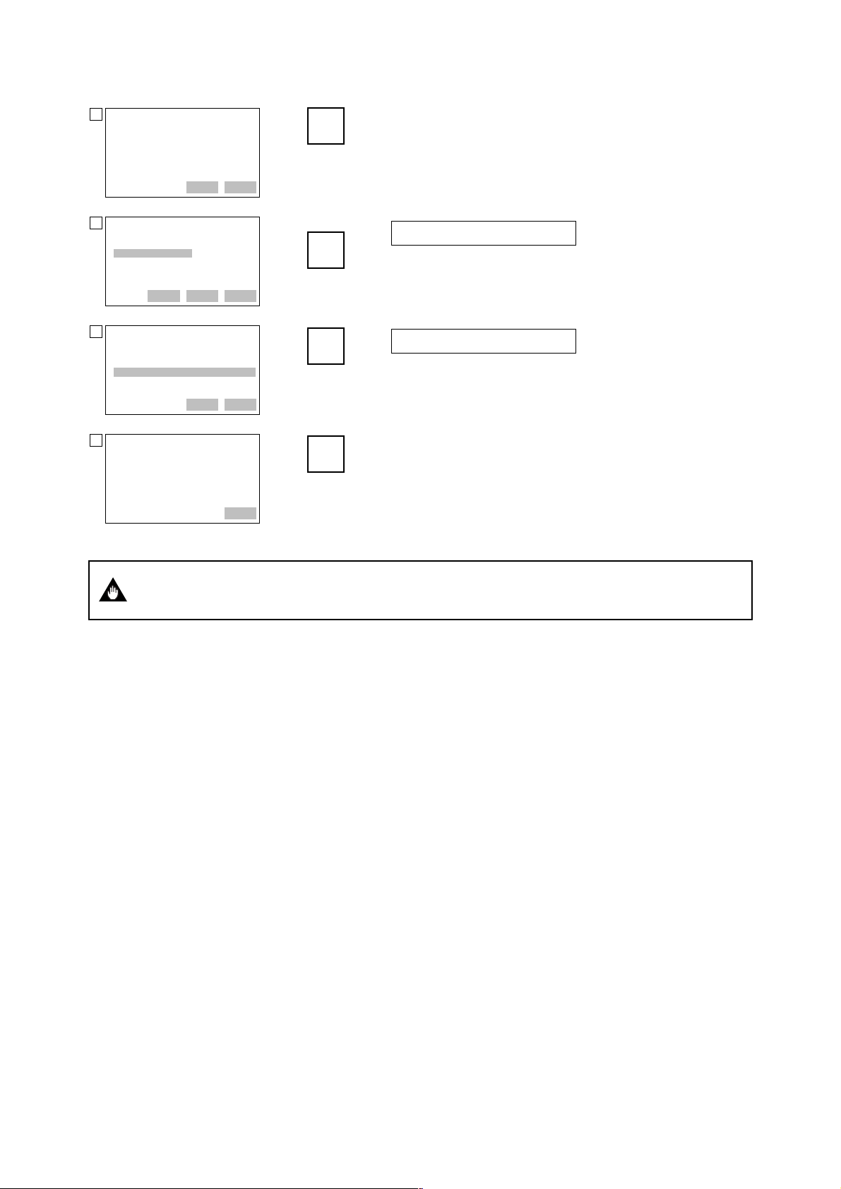
ADMAG SE :
11
Settting fld dev
output to 20mA
HELP SAVE ABORT OK
F4
(OK)
7. OPERATION VIA HART COMMUNICATOR
Press OK (F4). The output signal of 100% is output.
ADMAG SE :
12
Enter meter value
5.000000
5.000000
HELP DEL ABORT ENTER
ADMAG SE :
13
Scaled output: 5.210
equal readout
device?
1 Yes
2 No
HELP DEL ABORT ENTER
ADMAG SE :
14
NOTE-Loop may be
returned to automatic
control
DEL DEL ABORT OK
IMPORTANT
‘5.21’
F4
Voltmeter reading: 5.210
Enter the reading of the voltmeter (5.210), and press ENTER
(ENTER)
F4
(ENTER)
(F4).
Voltmeter reading: 5.000
Select “Yes” and press ENTER (F4).
“Returning fld dev to original output” appears.
F4
(OK)
Press OK (F4).
D/A trim should be executed only at single range mode. If D/A trim is executed at Bi
direction mode, it is feared that the current output becomes 108%.
7-18
IM 1E10B0-01E
Page 71

7. OPERATION VIA HART COMMUNICATOR
(5) Burst Mode
The ADMAG SE continuously sends the data stored in it when the burst mode is set
“On”. Either one of instantaneous flow rate, output in %, totalization values and current
output can be selected and sent. The data is sent intermittently as a digital signal when
the ADMAG SE is set in the burst mode.
Setting of Burst Mode
Call up “Burst option” display.
1. Device setup 4. Detailed setup 4. Outputs 3. HART output 4. Burst option
ADMAG SE :
Burst option
********
PV
% range/current
Process vars/crnt
HELP DEL ESC ENTER
Call up “Burst mode” display.
3. HART output 3. Burst mode
ADMAG SE :
1
Burst mode
Off
Off
On
DEL DEL ESC ENTER
ADMAG SE :
2
HART output
1 Poll addr 0
2 Num req preams 5
3 Burst mode On
4 Burst option PV
HELP SEND HOME ENTER
Releasing from “Burst Mode”
Call up “Burst mode” display, and set “Off”.
F4
(ENTER)
F2
(SEND)
F4
(ENTER)
F2
(SEND)
Set the data to be sent.
• Instantaneous flow rate (PV)
• Output in % and current output (% range/current)
• Instantaneous flow rate, totalization value* and current
output (Process vars/crnt)
* “Totl”, “Reverse total” or “Diff. total”
Set “ON” and press ENTER (F4).
Press SEND (F2).
7-19
IM 1E10B0-01E
Page 72

7. OPERATION VIA HART COMMUNICATOR
(6) Multidrop Mode
Field devices in multidrop mode refer to the connection of several field devices on a
communication single line. Up to 15 field devices can be connected when set in the
multidrop mode. To activate multidrop communication, the field device address must be
changed to a number from 1 to 15. This change deactivates the 4 to 20 mA output and
turns it 4 mA. Refer to Fig. 7.1.2 for the load resistance.
Setting of Multidrop Mode
Call up “Poll addr” display.
1. Device setup 4. Detailed setup 4. Outputs 3. HART output 1. Poll addr
ADMAG SE :
Poll addr
0
0
HELP DEL ESC ENTER
‘1’
F4
(ENTER)
F2
(SEND)
Set the polling address (a number from 1 to 15) and press
ENTER (F4).
Then, press SEND (F2) to send the data.
Call up “Auto Poll” display.
HART output Online Menu Main Menu 4. Utility 1. Configure Communication
ADMAG SE :
1
HART output
1 Poll addr 1
2 Num req preams 5
3 Burst mode On
4 Burst option PV
HELP SAVE HOME ENTER
ADMAG SE :
2
Online
1 Device setup
2 PV 20Cum/h
3 PV AO 20mA
4 Span 20Cum/h
HELP SAVE HOME ENTER
HART Communicator
3
1 Offline
2 Online
3 Frequency Device
4 Utility
HELP SEND HOME ENTER
HART Communicator
4
Utility
1 Configure Communic
2 System Information
3 Listen for PC
4 Storage Location
5 Simulation
HELP SEND HOME ENTER
F3
(HOME)
JKL
4
1. Polling
Return to “Online Menu” with HOME (F3).
Return to “Main Menu” with a “previous” key.
Select “Utility”.
Select “Configure Communication”.
HART Communicator
5
Configure Communicat
1 Polling
2 Contrast
3 Off Time
4 Ignore diagnostics
HELP SEND HOME ENTER
Select “Polling”.
7-20
IM 1E10B0-01E
Page 73
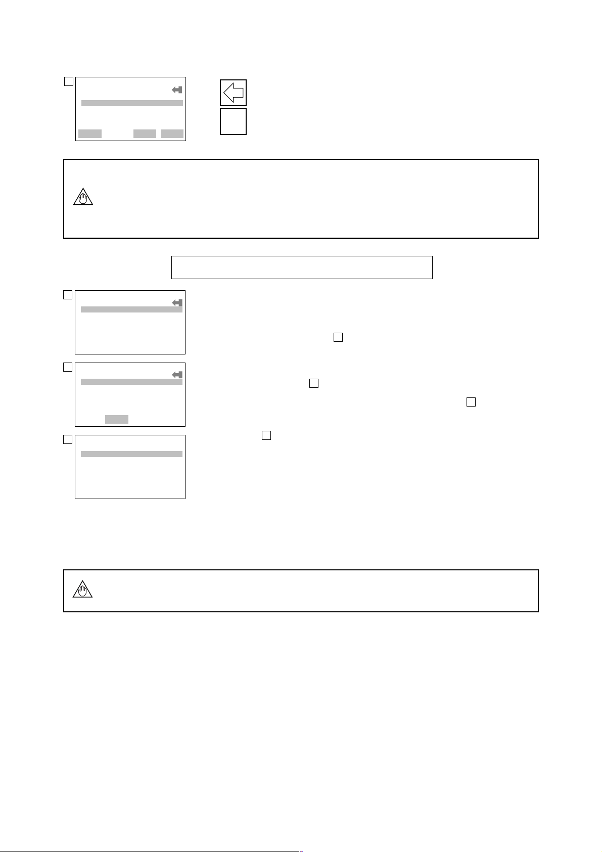
HART Communicator
6
Polling
Never Poll
Never Poll
Ask Before Polling
Always Poll
Digital Poll
HELP SAVE ESC ENTER
NOTE
HART Communicator
1
Online
1 1: FIC-1A
2 2: FIC-2A
3 3: PIC-1A
DEL DEL ESC ENTER
ADMAG SE:FIC-1A:
2
Online
1 Device setup
2 PV
3 PV AO
4 Span
HELP SAVE HOME ENTER
HART Communicator
3
1 Offline
2 Online
3 Frequency Device
4 Utility
7. OPERATION VIA HART COMMUNICATOR
Select “Digital Poll” and press ENTER (F4).
×3
F4
(ENTER)
1. If “Never Poll” is set in “Polling” when the address is set, “Online Menu” cannot
be called up and displayed. Be sure to set “Digital Poll” in “Polling” after setting
the polling address.
2. When the same polling address is set for two or more field devices in multidrop
mode, communication with these field devices is disabled.
Example: Communication when set in the multidrop mode.
(1) The HART Communicator searches for the field device is set in the
multidrop mode when the HART Communicator is turned on.
When the HART Communicator is connected to the field device, the tag
will be displayed (display ).
1
(2) Select the desired field device. After that, normal communication with the
selected field device is possible. However, the communication speed is slow
in this case (display ).
(3) To communicate with another field device, call up display , and select
2
3
“Online”.
(4) Display will appear. Repeat the above operation.
1
HELP SAVE HOME ENTER
Releasing from Multidrop Mode
First, call up the “Poll addr” display, and set the address to 0.
Second, call up the “Polling” display, and set “Never Poll”.
If the above releasing method is carried out in the reverse order, “Online Menu” can
NOTE
not be called up.
7-21
IM 1E10B0-01E
Page 74

(7) Write Protection
Write protection function is used to prevent unauthorized data being written into the
device, ADMAG SE. This function becomes active by entering a password in “New
password”. Write protection status is released for 10 minutes by entering the password
in “Enable wrt 10min”.
When the write protection function is active, data setting changes in all parameters of
NOTE
the ADMAG SE are inhibited and cannot be changed using either the HART Communicator or the ADMAG SE front panel key switches.
Setting Password
Example: Set the password to “1 2 3 4”.
Call up “Wrt protect menu” in Hot key menu
Hot key 2. Wrt protect menu2. Wrt protect menu
ADMAG SE :
1
Hot key
1 Span 1 m/s
2 Wrt protect menu
VWX
2
7. OPERATION VIA HART COMMUNICATOR
3. New password
Select “Wrt protect menu”.
HELP SAVE HOME ENTER
ADMAG SE :
2
Wrt protect menu
1 Write protect No
2 Enable wrt 10min
3 New password
4 Software seal Keep
HELP SAVE
ADMAG SE :
3
Enter new password to
change state of write
protect
HELP DEL ABORT ENTER
ADMAG SE :
4
Re-enter new password
within 30 seconds:
1234
1234
HELP DEL ABORT ENTER
ADMAG SE :
5
Change to New password
ABORT ENTER
YZ /
3
Select “New Password”.
Set “1 2 3 4” and press ENTER (F4).
STU1VWX2YZ /3JKL
F4
(ENTER)
STU1VWX2YZ /3JKL
F4
(ENTER)
Set “1 2 3 4” again and press ENTER (F4).
“Write protect” status changes from “No” to “Yes”.
4
4
DEL DEL
ADMAG SE :
6
It changed the state
of protection related
password
HELP DEL OK
ABORT OK
ABORT
F4
(OK)
Press OK (F4).
7-22
IM 1E10B0-01E
Page 75

Changing Password
Example: Change the password from “1 2 3 4” to “6 7 8 9 A”.
Call up “Wrt protect menu” in Hot key menu
Hot key 2. Wrt protect menu 2. Enable wrt 10min
ADMAG SE :
1
Enter current
password to enable to
write for 10
minutes:
HELP DEL ABORT ENTER
ADMAG SE :
2
Release the write
protection for 10
minutes.
DEL DEL ABORT OK
ADMAG SE :
3
If you wish to
release completely,
you have to change
password to all of
spaces.
HELP DEL ABORT OK
2. Wrt protect menu
“1 2 3 4”
F4
(ENTER)
F4
F4
Enter the password and press ENTER (F4).
Press OK (F4).
Write protection status is released for 10 minutes.
(OK)
Press OK (F4).
(OK)
7. OPERATION VIA HART COMMUNICATOR
ADMAG SE :
4
Wrt protect menu
1 Write protect No
2 Enable wrt 10min
3 New password
4 Software seal Keep
HELP SAVE ABORT OK
ADMAG SE :
5
Enter new password to
change state of write
protect
HELP DEL ABORT ENTER
ADMAG SE :
6
Re-enter new password
write 30 seconds:
6789A
6789A
HELP DEL ABORT ENTER
ADMAG SE :
7
Change to New password
HELP DEL
ABORT OK
YZ/
3
“6 7 8 9 A”
F4
(ENTER)
“6 7 8 9 A”
F4
(ENTER)
Select “New password”.
Set “6 7 8 9 A” and press ENTER (F4).
Set “6 7 8 9 A” again and press ENTER (F4).
ADMAG SE :
8
It changed the state
of protection related
password.
HELP DEL OK
ABORT
F4
(OK)
Press OK (F4).
7-23
IM 1E10B0-01E
Page 76

NOTE
7. OPERATION VIA HART COMMUNICATOR
1. “Enable wrt 10min” releases write protection status for 10 minutes. While write
protection status is released, it is possible to enter a new password in the “New
password”. It will not be possible when 10 minutes have elapsed.
2. To release write protection status completely, enter 8 spaces in the “New password”. This causes “Write protect” status to change from “Yes” to “No”.
3. If both ADMAG SE and HART Communicator power off and on again within 10
minutes after releasing of write protection status, the enabled write protection
status becomes unavailable.
4. “L01:TUNING” which is the write protection for ADMAG SE front panel key
switches, can be set “00:INHIBIT” or “01:ENABLE” only when “Write Protect”
on HART Communicator shows “No”.
* “Joker password” and “Software Seal”
When you forget the password that has been registered, it is possible to release the
mode for 10 minutes by using a joker password. Enter YOKOGAWA to release
“Write protect” status for 10 minutes. If this joker password is used, the status
shown in the parameter “Software seal” is changed from “Keep” to “Break”. Press
Hot key and select “2. Wrt Protect menu”. Current status is shown in “4. Software
seal”. This status will be returned from “Break” to “Keep” by registering a new
password.
(9) Other Functions and Operation
Please set the other needed parameters with the same way. The following document is
useful for your operation.
Product Manual for the HART Communicator: MAN 4250
7-24
IM 1E10B0-01E
Page 77

8. ACTUAL OPERATION
After you have installed the flow tube into the process piping, wired the input / output
terminals, set up the required parameters and performed the pre-operation zero adjustment, the magnetic flowmeter should output an accurate flow signal from its terminals
as soon as the measured fluid begins to flow.
This section describes procedures of zero adjustment and alarms countermeasure.
8.1 Pre-Operation Zero Adjustment
This section describes three procedures for performing zero adjustment. Using the data
setting keys on the converter front panel, using a BT200 or using a Hart Communicator.
Zero adjustment is made to set the instrument output to 0% (4mA) when the flow rate is
0.
1. Zero adjustment should be done only when the fluid is filled in the flow tube and the
IMPORTANT
fluid velocity is completely zero by closing the valve.
2. Zero adjustment should be done prior to the other operation. For 20 seconds during
the zero adjustment, any setting cannot be accepted.
8. ACTUAL OPERATON
8.1.1 Zero Adjustment Using Data Setting Keys
Display Description
Call up “C01” (ZERO TUNING) on the setting mode and touch SET key to make
the data display.
SET
SET
SET
SET
Code
00
INHIBIT
01
ENABLE
×2
Call up “C02” (MAGFLOW ZERO) and touch SET key.
Touch SET key twice.
×2
“-ZEro-” is displayed for about 20 seconds.
Content
Set “01” and touch SET key twice.
It changes into the Flow Rate Display Mode after the zero adjustment is completed.
8-1
IM 1E10B0-01E
Page 78

8.1.2 Zero Adjustment Using BT200
Display Description
8. ACTUAL OPERATON
MENU
A: DISPLAY
B: SET
C: ADJUST
D: DISP SEL
E: TOTAL SET
F: PULSE SET
HOME SET ADJ ESC
ENTER
PARAM
C01: ZERO TUNING
INHIBIT
C02: MAGFLOW ZERO
0.05
C60: SELF CHECK
GOOD
DATA DIAG ESC
ENTER
SET
C01: ZERO TUNING
ENABLE
ENTER
PARAM
C01: ZERO TUNING
ENABLE
C02: MAGFLOW ZERO
0.05
C60: SELF CHECK
GOOD
DATA DIAG ESC
Call up the menu panel and select “C:ADJUST” with the arrow key.
Press ENTER key to call up the panel displaying the parameter
subitems.
Confirm the inverse video bar is on “C01:ZERO TUNING”.
Press ENTER key to call up the data setup panel and select
“ENABLE”.
Press the ENTER key to set the data and return to the parameter sub
items panel. Select “C02:MAGFLOW ZERO”with the arrow key.
ENTER
SET
C02: MAGFLOW ZERO
0.05
+00.05
CLR ESC
ENTER
SET
C02: MAGFLOW ZERO
AUTOZERO
FEED NO OK
PARAM
C01: ZERO TUNING
ENABLE
C02: MAGFLOW ZERO
0.02
C60: SELF CHECK
GOOD
DATA DIAG ESC
Pressing the ENTER key causes the data setup panel to be displayed.
×2
While “C02:MAGFLOW ZERO” is displayed, press the ENTER
key twice at an interval of a few seconds.
Then, “AUTO ZERO” is now displayed.
F4
After about 20 seconds, pressing the “F4” [OK] of the function key
causes the menu panel to be displayed. The zero correction is
displayed. Then the panel returns to data display mode.
8-2
IM 1E10B0-01E
Page 79

8.1.3 Zero Adjustment Using HART Communicator
Call up “Zero tuning” display.
1. Device setup 2. Diag/Service 1. Test device 3. Zero tuning
8. ACTUAL OPERATON
ADMAG SE :
Zero tuning
Enable
Inhibit
Enable
DEL DEL ESC ENTER
Call up “Auto zero” display.
1. Test device 2. Auto zero
ADMAG SE :
1
About to enter auto
zero
DEL DEL ABORT OK
ADMAG SE :
2
waiting for auto zero
to complete
DEL DEL ABORT ENTER
ADMAG SE :
3
Auto zero passed
F4
(ENTER)
F2
(SEND)
F4
(OK)
F4
Select “Enable” and press ENTER (F4) and SEND (F2).
Press OK (F4).
Wait for about 20 seconds.
Press OK (F4).
HELP SEND ABORT OK
IMPORTANT
(OK)
This parameter is only for execution.
1. Zero adjustment should be done only when the fluid velocity is completely zero by
closing the valve.
2. Do not turn off the power to the ADMAG SE immediately after zero adjustment.
Powering off within 20 seconds after zero adjustment will return adjustment to the
previous setting.
8-3
IM 1E10B0-01E
Page 80

8.2 Self-diagnostics Functions
The self-diagnostics function displays instrument internal errors, input/output signal
abnormalities, setting errors, and other problems.
When an alarm occurs, the alarm number that the error has occurred and normal data
are alternately indicated on the indicator of ADMAG SE.
However, alarms are only displayed during flow rate data display mode and when
parameter numbers are being changed in the setting mode. (Alarms are not displayed
when data items are being changed.)
The current output during the alarm occurrence can be selected from among the
followings. See “8.2.1 Output Status during Alarm Occurence.”
• 2.4mA or less
• 4mA
• HOLD
• 21.6mA or more
When the BT200 is used, alarms are displayed in “A60 to N60:SELF CHECK”
parameter.
When the HART Communicator is used, alarms are displayed in “Status group 1 to
3” parameters. There are two methods for self-diagnostics, every transmission and
manually executing the “Self test” command. See “8.2.2 Self-diagnostics Using
HART Communicator.”
When an error message appears, follow “8.2.3 Error Description and Countermea-
sure.”.
8. ACTUAL OPERATON
8.2.1 Output Status during Alarm Occurrence
Display detail
Indicator
of SE
--- GOOD Self test OK ON Normal Normal
--- ERROR Error OFF Fixed* Stop
Err-02 uP FAULT uP fault OFF 21.6mA or more** Stop
Err-03 EEPROM FAULT EEPROM fault OFF 21.6mA or more** Stop
Err-05 A/D FAULT A/D fault OFF Fixed* Stop
Err-06 SIGNAL OVERFLOW Signal overflow OFF Fixed* Stop
Err-07 COIL OPEN Coil open OFF Fixed* Stop
Err-08 SP AN VEL.>10m/s Vel. span>10m/s OFF Fixed* Stop
Err-09 SP AN VEL.<0.3m/s V el. span<0.3m/s OFF Fixed* Stop
Err-10 P.SPAN>1000p/s P.span>1000p/s OFF Fixed* Stop
Err-11 P.SPAN>500p/s P.span>500p/s OFF Fixed* Stop
Err-12 P.SPAN>25p/s P.span>25p/s OFF Fixed* Stop
Err-13 P.SPAN>15p/s P.span>15p/s OFF Fixed* Stop
Err-14 P.SPAN>10p/s P.span>10p/s OFF Fixed* Stop
Err-15 P.SPAN>5p/s P.span>5p/s OFF Fixed* Stop
Err-16 P.SPAN<.0001p/s P.span<.0001p/s OFF Fixed* Stop
Err-17 T.SPAN>1000p/s T.span>1000p/s OFF Fixed* Stop
Err-18 T.SPAN>.0001p/s T.span<.0001p/s OFF Fixed* Stop
Err-19 4-20 LMT ERROR Analog lmt error OFF Fixed* Stop
Err-20 EMPTY PIPE Empty pipe OFF Fixed* Stop
Err-21 MULTIRANGE ERROR Multi range err OFF Fixed* Stop
Err-22 COIL SHORT Excitation failure OFF Fixed* Stop
Err-23 EEPROM NO SET EEPROM no set OFF 21.6mA or more** Stop
Err-24 EEPROM DEFAULT EEPROM default OFF Fixed* Stop
Err-25 — Dev id not entered OFF Fixed* Stop
Note) *Depending on the setting in “4-20 ALM OUT (Analog alarm out)”.
**When optional code /C1 is selected, current output becomes 2.4mA or less.
BRAIN Terminal
HART
Communicator
Alarm
Contact
Output
Current Output
Total/Pulse
Output
8-4
IM 1E10B0-01E
Page 81

8.2.2 Self-diagnostics Using HART Communicator
Self-diagnostics of the ADMAG SE and check of incorrect data setting can be carried
out with the HART Communicator. There are two methods for self-diagnostics of the
ADMAG SE, self-diagnostics for every transmission and manually executing the “Self
test” command. When an error message appears, follow “8.2.3 Error Description and
Countermeasure.”
Call up “Test/Status” setting display.
1. Device setup 2. Diag/Service 1. Test device 1. Test/Status
ADMAG SE :
1
Test/Status
1 Status
2 Self test
HELP SAVE HOME ENTER
VWX
2
Select “Self test”.
8. ACTUAL OPERATON
ADMAG SE :
2
Self test OK
DEL DEL ABORT OK
ADMAG SE :
3
Test/Status
1 Status
2 Self test
HELP SAVE HOME OK
ADMAG SE :
4
Status
1 Status group 1
2 Status group 2
3 Status group 3
HELP SAVE HOME OK
ADMAG SE :
5
group 1
Error OFF
uP fault OFF
EEPROM fault OFF
A/D fault OFF
Signal overflow OFF
HELP DEL ABORT EXIT
F4
(OK)
STU
1
If there is no error detected, “Self test OK” will be displayed.
Press OK (F4).
When an error occurs, an error message appears and the results
of self-diagnostics appear in the “Status”.
Call up “Status”.
The status menu is separated 3 groups. About items of each
group, see “8.2.3 Error Description and Countermeasure”.
Select the desired group.
If there is no error, the result of diagnostics is indicated as
“OFF”. If “ON” is indicated, a countermeasure for that error is
necessary.
8-5
IM 1E10B0-01E
Page 82

8.2.3 Error Description and Countermeasure
Display detail
Indicator
BRAIN T erminal HART Communicator
of SE
--- GOOD
--- ERROR
Err-02 uP FAULT
Err-03 EEPROM FAULT
Err-05 A/D FAULT
Err-06 SIGNAL
OVERFLOW
Err-07 COIL OPEN
Err-08 SPAN VEL.>10m/s
Err-09 SPAN VEL.<0.3m/s
Err-10 P.SPAN>1000p/s
Err-11 P.SPAN>500p/s
Err-12 P.SPAN>25p/s
Err-13 P.SPAN>15p/s
Err-14 P.SPAN>10p/s
Err-15 P.SPAN>5p/s
Err-16 P.SPAN<.0001p/s
Err-17 T.SPAN>1000p/s
Err-18 T.SPAN>.0001p/s
Err-19 4-20 LMT ERROR
Err-20 EMPTY PIPE
Err-21
MULTIRANGE
ERROR
Err-22 COIL SHORT
Err-23 EEPROM NO SET
Err-24 EEPROM
DEFAULT
Err-25 ---
—
Status
group 1
Status
group 2
Status
group 3
Self test OK
Error
uP fault
EEPROM fault
A/D fault
Signal overflow
Coil open
Vel. span>10m/s
Vel. span<0.3m/s
P.span>1000p/s
P.span>500p/s
P.span>25p/s
P.span>15p/s
P.span>10p/s
P.span>5p/s
P.span<.0001p/s
T.span>1000p/s
T.span<.0001p/s
Analog lmt error
Empty pipe
Multi range err
Excitation failure
EEPROM no set
EEPROM default
Dev id not
entered
8. ACTUAL OPERATON
Description Countermeasure
Normal status
Alarm occurrence
(At occurrence of error
No.2 to 25)
Microprocessor failure
EEPROM failure
A/D converter failure
Excessive input signal
Flow tube coil open-circuit
Span velocity setting
exceeds 11m/s.
Span velocity setting is
0.2m/s or less.
Pulse output rate exceeds
1100p/s at 50% duty.
It exceeds 1000p/s at
0.5ms pulse width.
Pulse output rate exceeds
500p/s at 1ms pulse width.
Pulse output rate exceeds
25p/s at 20ms pulse width.
Pulse output rate exceeds
15p/s at 33ms pulse width.
Pulse output rate exceeds
10p/s at 50ms pulse width.
Pulse output rate exceeds
5p/s at 100ms pulse width
Pulse output rate is
0.00005p/s or less.
Totalization rate exceeds
1100p/s.
Totalization rate is
0.00005p/s or less.
Analog low limit setting
exceeds analog high limit
setting.
Pipe is not filled with
fluid or insulating material
attached to electrodes.
“Span” setting exceeds
“Forward span2” setting
at Auto 2 ranges.
Excitation circuit failure
Default values have not
been set in EEPROM.
EEPROM has been
initialized.
Device ID has not been
entered.
Contact the nearest
Yokogawa office or
service center.
Check the followings:
•
Mix of the signal, power
supply, excitation and
other cables
• Stray currents in the
measured fluid
•
Incorrect grounding
Contact the nearest
Yokogawa office or
service center.
Change settings.
Fill the flow tube with
fluid or clean the flow
tube inside.
Change settings.
Contact the nearest
Yokogawa office or
service center.
—
—
8-6
IM 1E10B0-01E
Page 83

9. MAINTENANCE
9.1 Loop Test (Test output)
This function enables you to set up any desired value, and to output it from the converter for test. Since this function corresponds to flow rate totalization display and pulse
output, this makes it possible to check operation of individual function.
The test functions of status output are also provided.
• Test outputs take priority of the flow signal.
Do not forget to return to the normal operation mode after the loop test.
• In case "BI DIRECTION" is set at OUTPUT FUNCTION (Parameter No. b10), the
setting range is available -108 to +108. Please set the loop test value in +/- percent-
IMPORTANT
age based on the larger flow span within forward and reverse flow span.
• In case "AUTO 2 RANGES" is set at OUTPUT FUNCTION (Parameter No.b10),
the loop test setting value should be set in percentage based on the second range.
9. MAINTENANCE
9.1.1 Settings for Test Output Using Data Setting Keys
(1) Current Output (Corresponding to flow rate, totalization display and pulse output value)
Display Description
Call up “H01” (TEST MODE) on the setting mode and touch SET key to make the
data display.
SET
Set “01” and touch SET key twice.
SET
×2
SET
SET
×2
Setting value:
–8 (–108) to 108%
Code
00
01
Call up “H02” (OUTPUT VALUE) and touch SET key.
Set the value in % span. (The figure shows a 100% setting.)
Flow rate, totalization display and pulse output functions correspond to this set
value.
Content
Normal operation
Test output
9-1
IM 1E10B0-01E
Page 84

(2) Status Output (For status output, alarm output or pulse output )
Display Description
Call up “H01” (TEST MODE) on the setting mode and touch SET key to make the
data display.
SET
9. MAINTENANCE
Set “01” and touch SET key twice.
SET
Code
00
01
×2
Content
Normal operation
Test output
Call up “H03” (STATUS OUT) and touch SET key.
SET
Select the output status and touch
SET key twice.
SET
Code
Normal operation
00
Contact output status (ON)
01
Contact output status (OFF)
×2
02
Content
9.1.2 Setting for Test Output Using BT200
(1) Current Output (Corresponding to flow rate, totalization display and pulse output value)
Display Description
Select “TEST” in “H01: TEST MODE”.
PARAM
H01:TEST MODE
TEST
H02:OUTPUT VALUE
100 %
H03:STATUS OUT
NORMAL
DATA
DIAG ESC
Code
NORMAL
TEST
Set the value in % of span in “H02:OUTPUT VALUE”. (The figure
shows a 100% setting.)
Flow rate, totalization display and pulse output functions correspond
to this set value.
Content
Normal operation
Test output
(2) Status Output (For status output, alarm output or pulse output status)
Display Description
Call up “H01: TEST MODE” on the setting mode and select
“TEST”.
PARAM
H01:TEST MODE
TEST
H02:OUTPUT VALUE
100 %
H03:STATUS OUT
NORMAL
DATA
DIAG ESC
Code
NORMAL
TEST
Select the status to be output in “H03: STATUS OUT”.
Code
NORMAL
CLOSED(ON)
OPEN(OFF)
Content
Normal operation
Test output
Normal operation
Contact output status (ON)
Contact output status (OFF)
9-2
Content
IM 1E10B0-01E
Page 85

9.1.3 Setting for Test Output Using HART Communicator
(1) Loop Test
This feature can be used to output a fixed current from 2.72 mA to 21.28 mA for loop
check.
Setting of Loop Test
Example: Set “12mA (50%)” as test output.
2. Loop test
Call up “Loop test” display.
1. Device setup 2. Diag/Service 2. Loop test
ADMAG SE :
1
WARN-Loop should be
removed from
automatic control
DEL DEL ABORT OK
F4
(OK)
Set the control loop in manual mode, and press OK (F4).
9. MAINTENANCE
ADMAG SE :
2
Choose analog output
level
1 4mA
2 20mA
3 Other
4 End
DEL DEL ABORT ENTER
ADMAG SE :
3
Output
4.000
HELP DEL ABORT ENTER
ADMAG SE :
4
Fld dev output is
fixed at 12.000 mA
DEL DEL ABORT OK
F4
(ENTER)
‘1 2’
F4
(ENTER)
F4
(OK)
Select “Other”, and press ENTER (F4).
×2
1. 4mA:
Outputs a 4mA current signal
2. 20mA:
Outputs a 20mA current signal
3. Other:
Sets a desired output with the alphanumeric keys
4. End: Exits
Enter “12”, and press ENTER (F4).
Press OK (F4).
A fixed current of 12mA is output.
NOTE
1. In case “Bi direction” is set at “Output function”, the setting range is available
with –108 to +108%. Please set the loop test value in +/– percentage based on the
larger flow span within forward and reverse flow span.
2. In case “Auto 2 ranges” is set at “output function”, the loop test setting value
should be set in percentage based on the second range.
9-3
IM 1E10B0-01E
Page 86

Releasing from Loop Test:
On “Loop test” display.
ADMAG SE :
1
Choose analog output
level
1 4mA
2 20mA
3 Other
4 End
DEL DEL ABORT ENTER
ADMAG SE :
2
NOTE-loop may be
Returned to automatic
control
DEL DEL ABORT OK
9. MAINTENANCE
There are four methods which cause the simulated output to return to a normal flow
reading.
1. Wait 10 minutes to automatically release from the test mode.
2. Turn the power off to the ADMAG SE.
3. Execute “End”. (See the following for this procedure.)
4. Abort “Loop Test”. Press ABORT (F3).
To finish the loop test, select “End”, and press ENTER (F4).
×3
F4
(ENTER)
F4
(OK)
Press OK (F4).
(2) Status Output Test
ADMAG SE has one status output for alarm or other functions. It can be output for test.
After the status output test, return the status output parameter to “Normal”.
Call up “Status out” display.
1. Device setup 2. Diag/Service 3. Status out
ADMAG SE :
1
Status out
Normal
Normal
Close (on)
Open (off)
DEL DEL ESC ENTER
ADMAG SE :
2
Diag/Service
1 Test device
2 Loop test
3 Status out
DEL SEND HOME ENTER
NOTE
When the status output test is executed, the current output is fixed 4 mA.
F4
(ENTER)
F2
(SEND)
Select “Closed” (example) and press ENTER (F4).
Press SEND (F2).
9-4
IM 1E10B0-01E
Page 87

9.2 Trouble Shooting
Although magnetic flowmeters rarely require maintenance, failures occur when the
instrument is not operating correctly.
The following trouble shooting are described from the viewpoint of receiving instrument
indication.
Please avoid removing the converter unit from the case, replacing fuse and alter LCD
CAUTION
9.2.1 No Indication
orientation. When these procedures are needed, please contact the nearest Yokogawa
offce.
START
Examine the converter display flashing whether an error is displayed.
9. MAINTENANCE
Is an error displayed?
YES
Deal with the error
according to
"8.2.3 Error Description
and Countermeasure."
NO
Is other display appearing?
YES
Does the flow arrow on
flow tube agree with the
flow direction?
YES
Check that
the flow tube is filled with
the liquid.
Is the flow
tube filled with the liquid?
YES
Demount the flow tube and
check the inside.
NO
NO
Contact the
NO
nearest
Yokogawa office
or service center.
Execute either of the
followings.
a. Install flow tube to make
flow arrow agree with the
flow direction.
b. Change the set value in
"B14: FLOW DIR".
Change the piping or
mounting to fill the flow tube
with the liquid.
Vertical mounting is effective.
Is foreign matter
sticking to the liner and
electrode?
YES
Remove foreign matter.
9-5
NO
Contact the nearest
Yokogawa office or service
center.
IM 1E10B0-01E
Page 88

9.2.2 Unstable Zero
START
Examine whether or not the
meter tube is filled with
liquid and the liquid does
not contain bubbles.
It is better to provide a vent
*1*1
hole on the downstream
side of the flow tube to
check bubbles.
9. MAINTENANCE
Is the flow
tube filled with liquid
completely?
YES
Are bubbles
contained in the liquid?
NO
Examine whether
or not the valves leak.
Are valves leaking?
NO
• Confirm the flow tube
grounding.
• Confirm whether or not
the grounding wire is
disconnected from the
earth terminal.
Is grounding complete?
YES
Recheck liquid property.
*1
NO
YES
YES
NO
Change the piping or
mounting to fill the flow
tube with the liquid.
Vertical mounting is
effective.
Mount a defoaming device
on the upstream side of the
flow tube.
Stop the leak by repairing
valves.
Complete grounding (The
resistance must be 100Ω or
less.) See “3.1.12
Grounding”.
• Does the liquid
conductivity vary or is
it easy to change?
• Is liquid conductivity
sometimes below
5µS/cm?
NO
Is the liquid likely to cause
deposits?
NO
Is the flowmeter
located near motors,
transformers, or other
electric equipmets.
NO
Insulation deterioration is
suspected.
Contact the nearest
Yokogawa office or service
center.
YES
YES
YES
9-6
a. Insure that the liquid
conductivity does not
change beyond fluid
limits.
b. Do not use the ADMAG
SE for liquid has
conductivity below
5µS/cm.
c. Decrease flow velocity
near the conductivity low
limit as much as possible.
• Remove dirt and scale on
near electrodes.
• Change to vertical
mounting.
Sufficiently shield the flow
tube.
Locate the flow tube as far
as possible from these
equipments.
IM 1E10B0-01E
Page 89

9.2.3 Disagreement of Indication with Actual Flow Rate
START
9. MAINTENANCE
Are parameters
correctly set?
YES
Examine filling with liquid in the flow tube, bubbles and
correct grounding.
Is zero adjustment
completed?
YES
Is the flow tube
completely filled with
liquid?
YES
Is the liquid free of
bubbles?
YES
Is grounding complete?
YES
Is the signal
cable completely end-
treated?
YES
Recheck the liquid
property.
Is the liquid likely
to cause deposits?
NO
Examine whether or not a
valve exists immediately
before the flow tube (on the
upstream side).
Is a valve located
immediately upstream of
the meter?
NO
Check the operation with the
AM012/SE calibrator, and
you will be able to confirm
the error of the converter or
of Flow Tube.
NO
NO
NO
NO
NO
NO
YES
YES
Set the parameters correctly.
Adjust zero when the flow tube is
completely filled with liquid and
the velocity is zero.
Change the piping or mounting to
fill the flow tube with the liquid.
Vertical mounting is effective.
Provide a defoaming device on the
upstream side of the flow tube.
Complete grounding. (The
resistance must be 100Ω or less.)
See “3.1.12 Grounding”
Completely perform endtreatment of the signal cable with
PVC tubes or insulation tape so
that the conductors, inner shields,
and outer shield do not contact
each other or with the case.
a. Remove scales. Especially
clean the electrodes and their
vicinity.
b. Remove scales with a soft
brush or a piece of soft cloth.
Never claw or scratch the
lining.
a. If a valve located immediately
upstream of the flow tube is
used half opened, the indication
may be affected with flow
turbulency.
b. Move the valve downstream of
the flow tube.
c. If the valve must be located on
the upstream side, allow for a
minimum distance to the flow
tube of 10 times the flow tube
diameter or use the valve fully
open.
Contact the nearest
YOKOGAWA office
or service center.
9-7
IM 1E10B0-01E
Page 90

10. OUTLINE
10. OUTLINE
■ STANDARD SPECIFICATIONS
■ Magnetic Flow Converter
Note •For models with no setting switches, a hand-
held terminal is necessary to set parameters.
•Pulse output, status output and alarm output
use commom terminals, therefore, these
functions are not available at the same time.
Excitation method: Pulsed DC excitation
Output Signal:
Current Output: 4 to 20 mA DC
(Load resistance 600Ω maximum)
Transistor Contact Output(Open-collector):
Pulse, alarm or status output selected by
parameter setting (Contact rating : 30V
DC(OFF), 200mA*(ON))
* In case of FM-Nonincendive type, 135mA
Communication:
HART or BRAIN
(Superimposed on the 4 to 20mA DC signal)
Conditions of Communication Line:
Load Resistance: (including cable resistance)
HART:230 to 600Ω, depending on q’ty of field
devices connected to the loop (multidrop
mode)
BRAIN:250 to 600Ω
Load Capacitance: 0.22 µF maximum
Load Inductance: 3.3 mH maximum
Distance from Power Line: 15 cm(0.6 ft) or more
(Parallel wiring should be avoided.)
Input Impedance of Receiver Connected to the
Receiving Resistance: 10kΩ or larger (at 2.4kHz)
(only for HART)
Maximum Cable Length: 2 km* (6500 ft) (when
polyethylene-insulated PVC-sheathed
* In case of FM-Nonincendive type, 1.5km(4875ft)
Instantaneous Flow Rate Display Function:
Flow rate can be displayed either in engineering
units or in percent of span. (for models with
indicator)
Totalizer Display Function:
Totalized volume in engineering units can be
displayed by setting a totalizing factor. (for
models with indicator)
Span Setting Function:
Volumetric flow setting is available by setting
volume unit, time unit, flow rate value and flow
tube size.
Volume Unit: m
barrel(=158.987L)
Velocity Unit: m, ft
Time Unit: sec., min., hour, day
Flow Tube Size: mm, inch
Data Security During Power Failure:
Data storage in EEPROM - no back-up battery
required.
Damping Time Constant:
Settable from 0.5 second to 200 seconds. (63%
response time)
control cables (CEV cables) are used)
3
, l, cm3, gallon(US),
Pulse Output Function:
Scaled pulse can be output by setting a pulse
factor.
Pulse Width: Duty 50% or fixed pulse width (0.5,
1, 20, 33, 50, or 100ms) - user selectable.
Output Rate: 0.0001 to 1000pps (when pulse
output function is selected.)
Status Output Function:
One of the followings is selected by parameter
setting.
• Auto 2 Ranges Status Output :
Indicates the selected range for automatic
dual range function.
• Forward and Reverse Status Output :
Indicates the flow direction for forward and
reverse flow measurement mode.
• Totalization Status Output :
Indicates that the internal totalized value
exceeds the set value.
• Low Limit Alarm :
Indicates that flow rate under the low limit set
value.
Alarm Output Function :
Indicates that an alarm occurs (Normal Close
Fixed).
Self Diagnostics Function:
Converter failure, flow tube failure, erroneous
setting, etc. can be diagnosed and displayed (for
models with indicator).
Touch Control:
Parameter setting operation by infrared switches.
(for models with indicator and setting switches)
Electrical Connection:
ANSI 1/2NPT female, DIN Pg13.5 female,
ISO M20 X 1.5 female, JIS G1/2 female
Terminal Connection: M4 size screw terminal
Case Material: Aluminum alloy
Coating: Polyurethane corrosion-resistant coating
Deep sea moss green (Munsell 0.6GY3.1/2.0)
Protection: IP67, NEMA 4X, JIS C0920
■ Magnetic Flow Tube
Protection: IP67, NEMA 4X, JIS C0920
water tight type
water tight type
Size in mm (inch):
15 (0.5), 25 (1), 40 (1.5), 50 (2), 80 (3), 100 (4),
150 (6), 200 (8)
Coating:
Polyurethane corrosion-resistant coating,
Deep sea moss green (Munsell 0.6Y3.1/2.0)
• All sizes of carbon steel flange type
• 150 and 200 mm of wafer type
No coating
• 15 to 100mm of stainless steel flange type
• 15 to 100mm of wafer type
Flow Tube Material:
Size 15 to 100mm (0.5 to 4in.)
Housing:Stainless steel
(15mm:SCS11, 25 to100mm:SUS304)
Mini-flange for wafer conn.: Stainless steel
(SUS430)
10-1
IM 1E10B0-01E
Page 91

10. OUTLINE
Flange: Carbon steel (SS400) or stainless steel
(SUS304)
Pipe: Stainless steel (15 to 25mm: SCS13,
40 to 100mm: SUS304)
Size 150 to 200mm (6 to 8in.)
Housing: Carbon steel (SS400)
Mini-flange for wafer conn.: Carbon steel
(SS400)
Flange: Carbon steel (SS400) or stainless steel
(SUS304)
Pipe: Stainless steel (SUS304)
Wetted Part Material :
Lining : Fluorocarbon PFA
Electrode : Stainless steel (SUS316L),
Hastelloy C (equivalent to Hastelloy
C-276), Titanium, Tantalum,
Platinum-iridium, Tangsten Carbide.
Earth Ring : Stainless steel (SUS316),
Hastelloy C (equivalent to Hastelloy
C-276), Titanium, PFA lining+Earth-
electrode(Tantalum/Platinum-
Iridium)
Note : Hastelloy is a registered trademark of Haynes
International Inc.
Gasket :
• VALQUA#4010 ; Fluoro rubber, viton (between
flow tube body and earth ring; for optional
code /FRG)
• Non-asbestos joint sheet sheathed with fluoro
resin PTFE (between earth ring and process
flange; for optional code /BSF)
Other gaskets between flow tube and earth ring;
• VALQUA#4010(Mixing#RCD970) ; Alkari
resistance gasket for PVC piping(Fluoro
rubber)
• VALQUA#4010(Mixing#RCD470) ; Acid
resistance gasket for PVC piping(Fluoro
rubber)
Contact YOKOGAWA office. (Refer to TI 1E6A0-06E)
Electrode Construction: External insertion type.
■ STANDARD PERFORMANCE
SE***DJ/EJ+SE14(Up to 300m cable length)
Accuracy :
Size in mm
(inch)
15 to 400
(0.5 to 16)
Repeatability: 0.1% of flowrate (1mm/s minimum)
Maximum Power Consumption:
Insulation Resistance:
Span in m/s
(ft/s)
0.3 to 1
(1 to 3)
1 to 10
(3 to 33)
Accuracy
0.5% of span
0.25% of span
(at indications below 50% of
span)
0.5% of rate
(at indications 50% of span or
more)
T01.EPS
10W for combination of flow tube and converter
• 100MΩ between power terminals and ground
terminal at 500V DC.
• 100MΩ between power terminals and each
output terminal at 500V DC.
• 20MΩ between each output terminal and
ground terminal at 100V DC.
Withstand Voltage:
• 1500V AC between power terminals and
ground terminal for 1 minute. (for -A1/A2 power
supply)
• 500V AC between power terminals and ground
terminal for 1 minute. (for -D1 power supply)
CAUTION
When performing the Voltage Breakdown Test,
Insulation Resistance Test or any unpowered
electrical test, wait 10 seconds after the power
supply is turned off before removing the housing
cover. Be sure to remove the Short Bar at terminal
“G”. After testing, return the Short Bar to its correct
position. Screw tightening torque should be 1.18Nm(0.88ft-lb)or more, because the G-terminal is
thought as a protective grounding and should
conform to the Safety Requirements.
Safety Requirement Standard:
IEC1010, EN61010
EMC Conformity Standard:
EN61326
EN61000-3-2, EN61000-3-3
AS/NZS 2064
Grounding: 100Ω or less
*In case of explosion proof type, the protective grounding
must be connected to a suitable IS grounding system.
■ NORMAL OPERATING CONDITION
Ambient Temperature: -20 to 60 °C (-4 to 140 °F)
Note: The minimum temperature is -10°C (14°F) in case
of the 40mm or lager sizes with the carbon steel
flange connection or wafer connection.
Ambient Humidity: 5 to 95%RH (no condensation)
Rated Power Supply Voltage:
100V AC/DC Version:
Range 80 to 127V AC, 47 to 63Hz
90 to 110V DC
230V AC Version: Range 180 to 264V AC
24V DC/AC Version:
Range 20.4 to 28.8 V DC/AC
Supplied Power and Max. Cable Length for 24V
DC version:
Allowable cable length m(ft)
1000(3300)
900(2970)
800(2640)
700(2310)
600(1980)
500(1650)
400(1320)
300(990)
200(660)
100(330)
0
20 22 24 26 28 (V)
Cable cross section area: 1.25 mm
Cable cross section area: 2 mm
Altitude at installation side:
Max.2000m above sea level
Installation category based on IEC1010:
II (See Note)
2
2
F01.EPS
10-2
IM 1E10B0-01E
Page 92

Pollution level based on IEC1010: 2(See Note)
Note: • The “Installation category” implies the regulation f or
impulse withstand voltage. It is also called the
“Overvoltage category”.“II” applies to electrical
equipment.
• “Pollution le v el” describes the degree to which a
solid, liquid or gas which deteriorates dielectric
strength is adhering. “2” applies to a normal indoor
atmosphere.
Fuse: 2A 250V (Time-Lag type)
Fluid Conductivity: 5µS/cm or larger
Measurable Flow Rate Range:
3
@10m/s
6.361
17.671
45.23
70.68
180.95
282.74
636.1
1,130.9
/h)
English Units (Size:in., Flowrate:GPM)
MIN. Range
Size
@1.0ft/s
0.5
1.5
0.6024
1
2.4095
5.422
2
3
4
6
8
9.638
21.685
38.56
86.74
154.21
SI Units (Size:mm, Flowrate:m
Size
15
25
40
50
80
100
150
200
MIN. Range
@0.3m/s
MAX. Range
0.1909
0.5302
1.3572
2.1206
5.429
8.483
19.086
33.93
Fluid Temperature and Pressure:
Pressure
MPa(kgf/cm
4(40){570}
2
){psi}
Size 15 mm(0.5in.) to 50 mm(2in.)
Size 80 mm(3in.) to 200 mm(8in.)
MAX. Range
@33ft/s
20.078
80.31
180.70
321.2
722.8
1,285.0
2,891.3
5140
T02.EPS
10. OUTLINE
2(20)(285}
1(10){142}
-0.1(-1){-14.2}
-40
(-40)
0
-10
(32)
(14)
Temperature °C(°F)
(104)
100
40
(212)
(266)
F02-1.EPS
Note 1: This limits sho w maximum allow ab le fluid pressure
for Flow Tube itself. Further fluid pressure should also
be limitted according to flange rating.
Note 2: The minimum temperature is -10°C (14°F) in case of
the 40mm or lager sizes with the carbon steel flange
connection or wafer connection.
■ TERMINAL CONNECTION
Terminal Symbols Description
G
POWER NPOWER L+
CUR+
CUR-
PLS/ALM+
PLS/ALM-
Ground and power supply
Current output 4 to 20 mA DC
Pulse, alarm or status output
Protective grounding
130
T03-3.EPS
■ SIZING DATA
SI Units
10.0
5.0
Flow velocity
(m/s)
1.0
0.5
0.3
0.1
English Units
33
Size: mm
1
Size: in.
15
10
Flowrate (m /h)
0.5
25
3
1
1.5
80
40
50
100
2
3
4
100
150
1,000
6
200
8
Flow velocity
(ft/s)
10-3
10
5.0
2.0
1.0
1.0 1,000
10
100
Flowrate (GPM)
F06.EPS
IM 1E10B0-01E
Page 93

■ MODEL AND SUFFIX CODE
SE115
SE202
SE204
SE205
SE208
SE210
SE215
SE220
M
. . . . . . . . . . . . . . . . . . . . . . . . . . .
N
. . . . . . . . . . . . . . . . . . . . . . . . . . .
J
. . . . . . . . . . . . . . . . . . . . . . . . . .
-D
. . . . . . . . . . . . . . . . . . . . . . .
-E
. . . . . . . . . . . . . . . . . . . . . . . .
A
. . . . . . . . . . . . . . . . . . . . .
B1S
. . . . . . . . . . . . . . .
B2S
. . . . . . . . . . . . . . .
E1S
. . . . . . . . . . . . . . .
E2S
. . . . . . . . . . . . . . .
E4S
. . . . . . . . . . . . . . .
K1S
. . . . . . . . . . . . . . .
K2S
. . . . . . . . . . . . . . .
A1C
. . . . . . . . . . . . . . .
A2C
. . . . . . . . . . . . . . .
D1C
. . . . . . . . . . . . . . .
D2C
. . . . . . . . . . . . . . .
D4C
. . . . . . . . . . . . . . .
J1C
. . . . . . . . . . . . . . .
J2C
. . . . . . . . . . . . . . .
G1C
. . . . . . . . . . . . . . .
A1S
. . . . . . . . . . . . . . .
A2S
. . . . . . . . . . . . . . .
D1S
. . . . . . . . . . . . . . .
D2S
. . . . . . . . . . . . . . .
D4S
. . . . . . . . . . . . . . .
J1S
. . . . . . . . . . . . . . . .
J2S
. . . . . . . . . . . . . . . .
G1S
. . . . . . . . . . . . . . .
-L
. . . . . . . . . . . . .
-P
. . . . . . . . . . . . .
-H
. . . . . . . . . . . . .
-T
. . . . . . . . . . . . .
-V
. . . . . . . . . . . . .
-W
. . . . . . . . . . . .
N
. . . . . . . . . .
S
. . . . . . . . . .
P
. . . . . . . . . .
H
. . . . . . . . . .
T
. . . . . . . . . .
V
. . . . . . . . . .
0
. . . . . . . . . .
2
. . . . . . . . .
3
. . . . . . . . .
4
. . . . . . . . .
-A1
. . . . .
-A2
. . . . .
-D1
. . . . .
NN
. .
H1
. .
H2
. .
V1
. .
V2 . .
/
Suffix CodeModel Description
Construction
Aux. Code
Output Signal
Lining
Process Connection
Electrode Material
Earth ring and
Earth electrode Material
Electrical Connection
Power Supply
Indicator
HI, H2 V1, V2
NN
T04.EPS
. . . . . . . . . . . . . . . . . . . . . . . . .
. . . . . . . . . . . . . . . . . . . . . . . . .
. . . . . . . . . . . . . . . . . . . . . . . . .
. . . . . . . . . . . . . . . . . . . . . . . . .
. . . . . . . . . . . . . . . . . . . . . . . . .
. . . . . . . . . . . . . . . . . . . . . . . . .
. . . . . . . . . . . . . . . . . . . . . . . . .
. . . . . . . . . . . . . . . . . . . . . . . . .
Optional Code
(Refer to Note2)
Note 1: Select PN40 when PN10, PN16, PN25 is required for 15 to 50mm, and select PN16 when PN10 is required for 80 to 150mm,
because of same mating dimensions.
Note 2: Only ANSI1/2NPT electrical connection is available for FM or CSA explosion proof type. JIS G1/2 electrical connection is not
available for any explosion proof type.
Nominal Size 15 mm (1/2in.)
Nominal Size 25 mm (1in.)
Nominal Size 40 mm (1 1/2in.)
Nominal Size 50 mm (2in.)
Nominal Size 80 mm (3in.)
Nominal Size 100 mm (4in.)
Nominal Size 150 mm (6in.)
Nominal Size 200 mm (8in.)
Integral type for General Purpose
Integral type for Explosion Proof
Always J
4-20 mA and Pulse or Alarm, Simultaneous 2-output (BRAIN)
4-20 mA and Pulse or Alarm, Simultaneous 2-output (HART)
Fluorocarbon PFA
ANSI 150 Wafer
ANSI 300 Wafer
DIN PN10 Wafer Only for 200 mm (Note 1)
DIN PN16 Wafer Only for 80 to 200 mm (Note 1)
DIN PN40 Wafer Only for 15 to 50 mm (Note 1)
JIS 10K Wafer
JIS 20K Wafer
ANSI 150 Flange Carbon Steel (SS400)
ANSI 300 Flange Carbon Steel (SS400)
DIN PN10 Flange Carbon Steel (SS400), Only for 200 mm (Note 1)
DIN PN16 Flange Carbon Steel (SS400), Only for 80 to 200 mm (Note 1)
DIN PN40 Flange Carbon Steel (SS400), Only for 15 to 50 mm (Note 1)
JIS 10K Flange Carbon Steel (SS400)
JIS 20K Flange Carbon Steel (SS400)
JIS F12 Flange Carbon Steel (SS400), Only for 80 to 200 mm
ANSI 150 Flange Stainless Steel (SUS304)
ANSI 300 Flange Stainless Steel (SUS304)
DIN PN10 Flange Stainless Steel (SUS304), Only for 200 mm (Note 1)
DIN PN16 Flange Stainless Steel (SUS304), Only for 80 to 200 mm (Note 1)
DIN PN40 Flange Stainless Steel (SUS304), Only for 15 to 50 mm (Note 1)
JIS 10K Flange Stainless Steel (SUS304)
JIS 20K Flange Stainless Steel (SUS304)
JIS F12 Flange Stainless Steel (SUS304), Only for 80 to 200 mm
Stainless Steel (SUS316L)
Platinum-iridum
Hastelloy C276 Equivalent
Tantalum
Titanium
Tungsten Carbide
Non Earth Ring
Stainless Steel (SUS316)
Platinum-iridum Electrode
Hastelloy C276 Equivalent
Tantalum Electrode
Titanium
JIS G1/2 Female
ANSI 1/2NPT Female
DIN Pg13.5 Female
ISO M20X1.5 Female
80 to 127 V AC/90 to 110 V DC
180 to 264 V AC
20.4 to 28.8 V DC/AC
Non Indicator
With Horizontal Indicator
With Horizontal Indicator and Setting SW
With Vertical Indicator
With Vertical Indicator and Setting SW
Integral Type Magnetic Flowmeter:
10-4
10. OUTLINE
IM 1E10B0-01E
Page 94

10. OUTLINE
Optional Specification
A: Available N: Not available
Applicable Model
Item
Waterproof Glands Waterproof glands are attached to all wiring ports. For JIS G1/2 only. A A A NNN/ECG
Waterproof Glands Waterproof glands (uniont joints) are attached to all wiring ports.
with Union JointsFor JIS G1/2 only. AAA NNN/ECU
Gaskets for PVC Pipe Gaskets are attached between earth ring and flow tube.
Bolt & Nut Assembly Stainless steel bolts/nuts and non-asbestos PTFE-wrapped gaskets assembly
For District Heating and Cooling Condensation proof for DHC use. Only for size 100 to 400mm
(For District Cooling) Terminal box; urethane resin potting. Wired 30m signal cable at factory. N N A NNN/DHC
DC Noise Suppression Eliminating DC Noise
Burn Out Down Current output at CPU failure is set to "Downward(2.4mA DC or less)".
Lightning Protector Built-in Lightning Protector A A N A A N /A
Painting Color Change Black, Munsell code : N1.5 A A A AAA/P1
Epoxy Coating Coating is changed to epoxy coating. A A A AAA/X1
High Anti-corrosion Coating Coating is changed to three-layer coating.
Oil-prohibited Use Degreased cleansing treatment A N A A N A /K1
Oil-prohibited Use
with Dehydrating Treatment Degreased cleansing treatment and packed with desiccant A N A A N A /K5
180 deg. Rotated Converter 180 deg. rotated converter for reversed flow direction A N N A N N /CRC
Material Certificate(Note 1) Reproduced material certificate for pipe, electrode, earth ring, mini-flange,
Hydrostatics Test Certificate With the following water pressure for 10min. The result is filled in Note column
Calibration Certificate Level 3:Declaration and Primary Standard List A A A AAA/L3
CENELEC ATEX(KEMA) Explosion Proof EExdm[ia]IICT6...T3;GroupII Category 2G N N N A N N /KF2
Explosion Proof Type Explosion Proof EExdIICT6;GroupII Category 2G N N N N A N
(Only for size 15 to 200mm) Explosion Proof EExdm[ia]IICT6...T3;GroupII Category 2G N N N N N A
FM Explosion Proof Type Explosion Proof N N N A N A /FF1
(Only for size 15 to 200mm) Explosion Proof/Nonincendive N N N N A N /FF1/FN1
CSA Explosion Proof Type Explosion proof N N N A N A /CF1
(Only for size 15 to 200mm)
SAA Explosion Proof Type Explosion Proof Exdm ia IICT6...T3 N N N A N N /SF1
(Only for size 15 to 200mm) Explosion Proof ExdIICT6 N N N N A N
GOST Certification Calibration Certificate for GOST (only for products produced at YMF) A A A AAA/GOS
Only for size 15 to 200mm A N A A N A /FRG
for wafer type Available with 15 to 200mm(0.5 to 8in.) A N A A N A /BSF
(Size 15mm(0.5in.) or larger: Conductivity 50S/cm or higher.) N A N N A N /ELC
Without /C1 : Upward(21.6mA or more) A A N A A N /C1
Jade Green, Munsell code : 7.5BG4/1.5 A A A AAA/P2
Metallic Silver A A A AAA/P7
(Urethane coating on two-layer Epoxy coating) A A A AAA/X2
and flange (depends on spec.). A N A A N A /M01
of our standard certificate. JIS10K, ANSI Class 150, DIN PN10 : 1.5MPa,
JIS20K, ANSI Class 300, DIN PN16 : 3.0MPa, JIS F12 : 1.25MPa A N A A N A /T01
Level 2:Declaration and Calibration Equipment List A A A AAA/L2
Level 4:Declaration and YOKOGAWA Measuring A A A AAA/L4
Explosion Proof Exdm ia IICT6...T3 N N N N N A
Specification
General
SE14
SE***NJ
CodeEx-proof
SE***EJSE14SE***DJSE***MJ
T09.EPS
10-5
IM 1E10B0-01E
Page 95

■ EXTERNAL DIMENSION
10. OUTLINE
15 mm (0.5 in) Wafer Type
192(7.6)
30(1.2)
With Indicator
182(7.2)
Non Indicator
61(2.4)61(2.4)
40(1.6)
With Indicator
30(1.2)
Non Indicator
Ground
Terminal
ø123
(4.8)
49(1.9)
67(2.6)
137(5.4)
44(1.7)
25 mm (1 in) to 100 mm (4 in) Wafer Type
192(7.6)
With Indicator
182(7.2)
Non Indicator
61(2.4)61(2.4)
30
40(1.6)
With
Indicator
30(1.2)
Indicator
Non
(1.2)
ø123
49(1.9)
(4.8)
67(2.6)
Ground
Terminal
H1
øD
150 mm (6 in) to 200 mm (8 in) Wafer Type
192(7.6)
30
(1.2)
With Indicator
182(7.2)
Non Indicator
61(2.4)61(2.4)
40(1.6)
Indicator
With
30(1.2)
Indicator
Non
60.5(2.4)
147(5.8)
*1
L
147(5.8)
147(5.8)
60(2.4)*
With Indicator
293(11.5)
With Indicator
H
With Indicator
Lining : Fluorocarbon PFA
Weight: 3.3kg(7.3 lb)
With Indicator Option: Add 0.22kg(0.49lb)
When no earth ring is selected the face to face
*
length is shorter by approx. 1.6 mm(0.06 in).
The face to face length is longer by approx. 22
mm(0.87 in) for earth ring(P,T).
The face to face length is longer by approx.
8.4mm(0.33 in) for optional code /FRG.
*1
When no earth ring is selected the face to face length
is shorter by approx. 1.6 mm(0.06 in).
The face to face length is longer by approx. 22 mm
(0.87 in) for earth ring(P,T).
The face to face length is longer by approx.8.4mm
(0.33 in) for optional code/FRG.
Model
Nominal size
Lining
Face-to-face
length
Outside
diameter
Height
Weight kg(lb)
*2 With Indicator Option: Add 0.22 kg(0.49 lb)
*1
SE202J
*1
L
67.5(2.7)
ø
D
240(9.4)
H
H1
*2
When no earth ring is selected the face to face
25(1)
60(2.4)
84(3.3)
3.6(7.9)
SE204J
260(10.2)
104(4.1)
3.8(8.3)
SE205
40(1.5)
Fluorocarbon PFA
70(2.8)
86(3.4)
285(11.2)
129(5.1)
4.2(9.1)
length is shorter by approx. 2 mm (0.08 in).
The face to face length is longer by approx. 32 mm
(1.3 in) for earth ring(P,T).
Unit : mm(inch)
J
SE208J
50(2)
80(3.1)
99(3.9)
307(12.1)
6.6(14.6)
80(3)
120(4.7)
129(5.1)
156(6.1)
SE210
100(4)
150(5.9)
155(6.1)
338(13.3)
182(7.2)
8.6(19.0)
J
Ground
Terminal
ø123
(4.8)
øD
49(1.9)
67(2.6)
H1
H1
The face to face length is longer by approx. 10.0mm
(0.40in) for optional code/FRG.
Model
Nominal size
H
*1
L
Lining
Face-to-face
length
Outside
diameter
Height
Weight kg(lb)
*2 With Indicator Option: Add 0.22 kg(0.49 lb)
SE215J
150(6)
Fluorocarbon PFA
*1
L
200(7.9)
218(8.6)
ø
D
407(16.0)
H
248(9.8)
H1
*2
16.1(35.5)
10-6
SE220
200(8)
250(9.8)
268(10.6)
457(18.0)
298(11.7)
24.2(53.4)
J
F03.EPS
IM 1E10B0-01E
Page 96

10. OUTLINE
■
15 mm (0.5 in) Flange Type
192(7.6)
With Indicator
30(1.2)
182(7.2)
Non Indicator
61(2.4)61(2.4)
40(1.6)
With Indicator
30(1.2)
Non Indicator
ø123
49(1.9)
(4.8)
67(2.6)
Ground
Terminal
øC
137(5.4)
øD
60.5(2.4)
N-øh
25 mm (1 in) to 50 mm (2 in) Flange Type
192(7.6)
With Indicator
30(1.2)
Ground
Terminal
182(7.2)
Non Indicator
61(2.4)61(2.4)
øC
⬚
40(1.6)
With Indicator
30(1.2)
Non Indicator
147(5.8)
øD
N-øh
49(1.9)
67(2.6)
H1
147(5.8)
200(7.9)
147(5.8)
*1
t
*1
L
With
Indicator
*2
(11.5)
*1
*2
293
With Indicator
*1
H
*2
*2
t
Unit : mm(inch)
When no earth ring is selected the face to face length is
shorter by approx. 1.6 mm(0.06 in).
The face to face length is longer by approx. 22 mm (0.87 in) for
earth ring(P,T).
The face to face length is longer by approx. 8.4 mm (0.33 in)
for optional code/FRG.
The thickness(t) is longer by approx. 11 mm (0.43 in) for earth
ring(P,T).
The thickness(t) is longer by approx. 4.2 mm (0.17 in) for
optional code/FRG.
J
J2
J1
Fluorocarbon PFA
95
95
(3.7)
(3.7)
70
70
(2.8)
(2.8)
15
15
(0.6)
(0.6)
15.8
17.8
(0.6)
(0.7)
4.9
5.0
(11.1)
SE115
15(0.5)
A1
88.9
(3.5)
60.5
(2.4)
15.7
(0.6)
15
(0.6)
4.6
(10.0)
A2
D4
95.3
95
(3.8)
(3.7)
66.5
65
(2.6)
15.7
(0.6)
18
(0.7)
5.0
(11.0)
(2.6)
14
(0.6)
19.8
(0.8)
4.5
(9.9)
4
Model
Nominal size
Flange T ype
Lining
Flange outside dial.
Pitch circle dia.
Number of holes
Dia. of holes
Thickness
Weight kg(lb)
*3 With Indicator Option: Add 0.22 kg(0.49 lb)
When no earth ring is selected the face to face length
is shorter by approx. 1.6 mm(0.06 in).
The face to face length is longer by approx. 22 mm
(0.87 in) for earth ring(P,T).
The face to face length is longer by approx. 8.4 mm
(0.33 in) for optional code/FRG.
The thickness(t) is longer by approx. 11 mm (0.43 in)
for earth ring(P,T).
The thickness(t) is longer by approx. 4.2 mm (0.17 in)
for optional code/FRG.
ø
D
ø
C
N
ø
h
*2
t
*3
(10.7)
Model
Nominal size
Flange T ype
Lining
Face to face length (ISO)
Flange outside dia.
Height
Pitch circle dia.
Number of holes
Dia. of holes
Thickness
Bolt hole pitch
Weight kg(lb)
*3 With Indicator Option: Add 0.22 kg(0.49 lb)
*3
J1
J2
Fluorocarbon PFA
*1
L
125
D
C
h
(4.9)
272
(10.7)
113
(4.4)
90
(3.5)
19
(0.7)
17
(0.7)
45
6.0
(13.0)
125
(4.9)
272
(10.7)
113
(4.4)
90
(3.5)
19
(0.7)
19
(0.7)
45
6.3
(13.9)
ø
H
H1
ø
N
ø
*2
t
⬚
SE202
25(1)
A1
200(7.9)
108
(4.3)
264
(10.4)
105
(4.1)
79.2
(3.1)
4
15.7
(0.6)
17.2
(0.7)
45
5.3
(11.7)
J
A2
124
(4.9)
272
(10.7)
113
(4.4)
88.9
(3.5)
19.1
(0.7)
20.7
(0.8)
45
6.5
(14.3)
D4
115
(4.5)
267
(10.5)
108
(4.3)
85
(3.3)
14
(0.6)
21
(0.8)
45
6.3
(13.9)
J1
J2
Fluorocarbon PFA
140
140
(5.5)
(5.5)
290
290
(11.4)
(11.4)
131
131
(5.2)
(5.2)
105
105
(4.1)
(4.1)
19
19
(0.7)
(0.7)
19
21
(0.7)
(0.8)
45
45
7.6
7.9
(16.8)
(17.4)
10-7
SE204J
40(1.5)
A1
200(7.9)
127
(5.0)
284
(11.1)
125
(4.9)
98.6
(3.9)
4
15.7
(0.6)
20.5
(0.8)
45
7.2
(15.9)
A2
155.4
(6.1)
298
(11.7)
139
(5.5)
144.3
(5.7)
22.4
(0.9)
23.5
(0.9)
45
9.5
(20.9)
D4
150
(5.9)
295
(11.6)
136
(5.4)
110
(4.3)
18
(0.7)
21
(0.8)
45
9.2
(20.3)
J1
J2
Fluorocarbon PFA
155
155
(6.1)
(6.1)
316
316
(12.4)
(12.4)
157
157
(6.2)
(6.2)
120
120
(4.7)
(4.7)
4
8
19
19
(0.7)
(0.7)
19
21
(0.7)
(0.8)
45
22.5
9.0
9.1
(19.8)
(20.0)
SE205J
50(2)
A1
200(7.9)
152.4
(6.0)
315
(12.4)
156
(6.1)
120.7
(4.8)
4
19.1
(0.7)
22.2
(0.9)
45
9.5
(20.9)
A2
165.1
(6.5)
321
(12.6)
162
(6.4)
127
(5.0)
4
19.1
(0.7)
25.2
(1.0)
22.5
11.1
(24.5)
D4
165
(6.5)
321
(12.6)
162
(6.4)
125
(4.9)
4
18
(0.7)
23
(0.9)
45
10.9
(24.0)
F04-1.EPS
IM 1E10B0-01E
Page 97

80mm (3in) to 100mm (4in) Flange Type
192(7.6)
With Indicator
182(7.2)
Non Indicator
61(2.4)61(2.4)
30(1.2)
Ground
Terminal
øD
Model
Nominal size
Flange Type
Lining
Face to face length (ISO)
Flange outside dia.
Height
Pitch circle dia.
Number of holes
Dia. of holes
Thickness
Bolt hole pitch
Weight kg(lb)
*3 With Indicator Option: Add 0.22 kg(0.49 lb)
*3
40(1.6)
With Indicator
30(1.2)
Non Indicator
ø123
(4.8)
49
(1.9)
147(5.8)
67(2.6)
H1
N-øh
øC
A2
209.6
(8.3)
351
(13.8)
197
(7.8)
168.1
(3.5)
22.4
(0.9)
32.2
(1.3)
22.5
17.6
(38.8)
D4
(7.9)
(13.6)
(7.4)
(6.3)
8
(0.7)
(0.9)
(29.9)
L
200
346
187
160
18
23.8
22.5
13.6
⬚
SE208J
80(3)
J1
J2
A1
185
(7.3)
338
(13.3)
179
(7.0)
150
(5.9)
19
(0.7)
21.8
(0.9)
22.5
11.7
(25.8)
(7.9)
(13.6)
(7.4)
(6.3)
8
(0.9)
25.8
(1.0)
22.5
15.6
(34.3)
200
346
187
160
PFA Lining
200(7.9)
190.5
(13.4)
152.4
23
(35.9)
(7.5)
341
182
(7.2)
(6.0)
19.1
(0.7)
27.7
(0.7)
45
16.3
4
*1
L
øD
H
H1
øC
N
øh
*2
t
⬚
*1
G1
(8.3)
(13.8)
(7.6)
(6.6)
(0.7)
21.8
(0.9)
14.0
(30.9)
211
351
192
168
4
19
45
With Indicator
*2
t
J1
J2
210
255
(8.3)
(8.9)
369
376
(14.5)
(14.8)
210
217
(8.3)
(8.5)
175
185
(6.9)
(7.3)
19
23
(0.7)
(0.9)
21.8
27.8
(0.9)
(1.1)
22.5
22.5
13.7
17.6
(30.2)
(38.7)
H
SE210J
100(4)
A1
PFA Lining
250(9.8)
228.6
(9.1)
378
(14.9)
219
(8.6)
190.5
(7.5)
19.1
(0.7)
27.7
(1.1)
22.5
18.3
(40.3)
Unit : mm(inch)
*1
When no earth ring is selected the face to face
length is shorter by approx. 1.6 mm(0.06 in).
The face to face length is longer by approx. 22
mm (0.87 in) for earth ring(P,T).
The face to face length is longer by approx.
0.84mm (0.33 in) for optional code/FRG.
The thickness(t) is longer by approx. 11 mm
*2
(0.43 in) for earth ring(P,T).
The thickness(t) is longer by approx. 0.42mm
(0.17 in) for optional code/FRG.
A2
D2
G1
254
220
391
232
22.4
34.8
22.5
24.8
(8.7)
374
(14.7)
215
(8.5)
180
(7.1)
18
(0.7)
23.8
(0.9)
22.5
15.6
(34.3)
23.8
(9.4)
383
(15.1)
224
(8.8)
195
(7.7)
4
19
(0.7)
21.8
(0.9)
45
26
(57.3)
8
(10.0)
(15.4)
(9.1)
200.2
(7.9)
(0.9)
(1.4)
(54.7)
10. OUTLINE
F05.EPS
80mm(3in) to 100mm(4in) Flange Type
192(7.6)
With Indicator
182(7.2)
Non Indicator
61(2.4)
30(1.2)
Ground
Terminal
øD
Model
Nominal size
Flange Type
Lining
Face to face length (ISO)
Flange outside dia.
Height
Pitch circle dia.
Number of holes
Dia. of holes
Thickness
Bolt hole pitch
Weight kg(lb)*3
*3 With Indicator Option: Add 0.22 kg(0.49 lb)
61(2.4)
⬚
40(1.6)
With Indicator
30(1.2)
Non Indicator
49
ø123
(1.9)
(4.8)
N-øh
øC
J1
*1
L
280
ø
D
(11.0)
438
H
(17.2)
279
H1
(10.7)
240
ø
C
(9.4)
8
N
23
ø
h
(0.9)
27
*2
t
(1.1)
22.5
⬚
28
(64.7)
67(2.6)
H1
J2
305
(12.0)
450.5
(17.8)
291.5
(11.5)
260
(10.2)
12
25
(1.0)
33
(1.3)
15
35
(77.2)
SE215J
150(6)
A1
PFA Lining
300(11.8)
279.4
(11.0)
437.7
(17.2)
278.7
(11.0)
240
(9.5)
8
22.3
(0.9)
30.4
(1.2)
22.5
30
(66.1)
147(5.8)
A2
317.5
(12.5)
450.7
(18.0)
297.8
(11.7)
270
(10.6)
12
22.3
(0.9)
41.5
(1.2)
15
45
(99.2)
L
D2
(11.2)
440.5
(17.4)
281.5
(11.1)
(9.4)
(0.9)
(1.1)
22.5
(66.1)
*1
285
240
22
27
30
8
With Indicator
*2
t
G1
J1
290
330
(11.4)
(13.0)
443
488
(17.4)
(19.2)
284
329
(11.2)
(13.0)
247
290
(9.7)
(11.4)
6
19
(0.7)
(0.9)
27
(1.1)
(1.1)
30
29
(64.0)
(86)
H
J2
350
342..5
(13.8)
(13.5)
498
493.4
(19.6)
(19.4)
339
335.5
(13.3)
(13.2)
305
298.4
(12.0)
(11.7)
12
12 8 8
23
25
(1.0)
27
35
(1.4)
15
15
39
49
(108)
*1
When no earth ring is selected the face to face
length is shorter by approx. 2 mm (0.08 in).
The face to face length is longer by approx. 32 mm
(1.3 in) for earth ring(P,T).
The face to face length is longer by approx. 10.0
mm (0.4 in) for optional code/FRG.
*2
The thickness(t) is longer by approx. 16 mm
(0.63 in) for earth ring(P,T).
The thickness(t) is longer by approx. 5.0 mm
(0.20 in) for optional code/FRG.
SE220J
200(8)
A1
A2
PFA Lining
350(13.8)
22.3
(0.9)
49.4
(1.9)
22.5
46
(101)
381
(15.0)
513.5
(20.2)
354.5
(14.0)
330.2
(13.0)
12
25.4
(1.0)
46.1
(1.8)
15
68
(149.9)
D1
220
(8.7)
493
(14.4)
334
(13.1)
295
(11.6)
(0.9)
(1.1)
22.5
(94.8)
G1
D2
342
340
(13.5)
(13.4)
494
493
(19.4)
(14.4)
335
334
(13.2)
(13.1)
299
295
(11.8)
(11.6)
22
29
43
12
22
(0.9)
29
(1.1)
15
44
(97.0)
8
19
(0.7)
29
(1.1)
22.5
45
(99.3)
F05-1.EPS
10-8
IM 1E10B0-01E
Page 98

11. PARAMETER LIST
11. PARAMETER LIST
11.1 Parameters for ADMAG SE Indicator and BRAIN Terminal
This chapter describes ADMAG SE parameters for its indicator and BRAIN Terminal.
● Description of Items
Indicator
BRAIN
Terminal
Name
Data Range,
Units
Decimal
Point
Default
Value
R/W
Description
Parameter number for ADMAG SE indicator
Parameter number for BRAIN terminal
Parameter name
The figure in ( ) shows the number for selecting
data on ADMAG SE indicator. The desired
number can be entered when ADMAG SE
indicator is in the setting mode.
Indicates the range of allowable settings and the
units used.16 alphanumerics can be entered when
“16 ASCII characters” is specified.
Numbers indicate the position of decimal point
and its range of movement within the data
display.
11-1
Example :
0 to 4 : Can be moved in the range 0 to 4
4 : Fixed at 4
Indicate initial set value (When shipped from the
factory)
R: Read only W: Write enabled
Describes the nature of the parameter
IM 1E10B0-01E
Page 99

List of Parameters for ADMAG SE Indicator and BRAIN Terminal
11. PARAMETER LIST
Indicator Name R/W DescriptionData Range, Units
— A00 DISPLAY R
A10 A10 FLOW RATE(%) –10.0 to 110.0% 1 R
A20 A20 FLOW RATE ±300.0 0 to 4 R
A30 A30 TOTAL 0 to 999999 0 W
A31 A31 REV.TOTAL 0 to 999999 W
A32 A32 DIF.TORAL –999999 to 999999 R
— A60 SELF CHECK GOOD R
BRAIN
Terminal
ERROR
µF FAULT
EEPROM FAULT
A/D FAULT
SIGNAL OVERFLOW
COIL OPEN
SPAN VEL.> 10 m/s
SPAN VEL.< 0.3 m/s
P.SPAN > 1000 p/s
P.SPAN > 500 p/s
P.SPAN > 25 p/s
P.SPAN > 15 p/s
P.SPAN > 10 p/s
P.SPAN > 5 p/s
P.SPAN < 0001 p/s
T.SPAN > 1000 p/s
T.SPAN < 0001 p/s
4 - 20 LMT ERROR
EMPTY PIPE
MULTIRANGE ERROR
COIL SHORT
EEPROM NO SET
EEPROM DEFAULT
Decimal
Point
Default
Value
Major outputs display functions.
Displays instantaneous flow rate in %.
Displays instantaneous flow rate in
egineering unit.
Displays and presets forward direction
totalized flow rate.
Displays and resets reverse direction
totalized flow rate.
Displays differential totalized flow rate
between forward and reverse.
(A32=A30–A31)
Displays self-check result.
See “8.2 Self-diagnostics Functions.”
11-2
IM 1E10B0-01E
Page 100

11. PARAMETER LIST
Indicator Name R/W DescriptionData Range, Units
BRAIN
Terminal
Decimal
Point
Default
Value
— B00 SET R
— B01 TAG NO. ASC II 16 characters W
b02 B02 DAMPING 0.5 to 200 sec 1 3.0 W
b03 B03 FLOW SPAN 1 to 3.0000 0 to 4 1.0000 W
b04 B04 FLOW UNIT (00) km3(10
(01) m
(02) l(liter)
(03) cm3(10
3
X
m3)mW
3
-2
3
X
m)
(04) M gal
(05) k gal
(06) gal
(07) m gal
(08) k bbl
(09) bbl
(10) m bbl
(11) µ bbl
(12) m
(13) ft
b05 B05 TIME UNIT (00)/ d / s W
(01) / h
(02) / m
(03) / s
b06 B06 SIZE UNIT (00)mm mm W
(01) inch
b07 B07 NOMINAL SIZE 1 to 3000.0 1 100.0 W
b08 B08 MF 0.2500 to 3.0000 1.000 W
b10 B10 OUTPUT FUNC (00) PULSE OUT PULSE W
(01) ALARM OUT OUT
(02) BI DIRECTION
(03) AUTO 2 RANGES
(04) LOW ALARM
(05) TOTAL SWITCH
b11 B11 4 - 20 ALM OUT (00) 2.4 mA OR LESS 21.6 mA W
(01) 4.0 mA OR
(02) HOLD MORE
(03) 21.6 mA OR MORE
b12 B12 POWER FREQ 47.00 to 63.00 Hz 2 50.00 W
Major parameter setting.
Sets tag no. up to 16 characters.
Sets damping time constant of output.
Sets flow span in selected unit.
Selects volume unit of flow span.
Selects time unit of flow span.
Selects flow tube nominal size unit.
Sets flow tube nominal size in selected unit.
Sets meter factor. (Actual flow test data
has been entered.)
Selects status output functions.
Selects current output during alarm
occurrence.
Sets AC power frequency for DC power
supply.
11-3
IM 1E10B0-01E
 Loading...