

Page 1

User’s
Manual
Model SDBT (Style R)
Distributor
IM 01B04T01-02E
IM 01B04T01-02E
12th Edition
Page 2

Blank Page
Page 3

Model SDBT (Style R)
Distributor
IM 01B04T01-02E 12th Edition
CONTENTS
1. INTRODUCTION ........................................................................................... 1-1
1.1 Inspection ............................................................................................................... 1-2
1.2 Documentation Conventions ................................................................................. 1-3
1.3 Notice ...................................................................................................................... 1-3
2. GEN ERA L ..................................................................................................... 2-1
2.1 Standard Specifications......................................................................................... 2-1
2.2 Model and Suffix Codes ......................................................................................... 2-2
2.3 Accessory ............................................................................................................... 2-2
Toc-1
3. INS TALLATION............................................................................................. 3-1
3.1 External Wiring ....................................................................................................... 3-1
3.2 Applicable Cables................................................................................................... 3-2
4. PRINCIPLES OF OPERA TION...................................................................... 4-1
4.1 Loop Isolation T ype (for SDBT-11 Type) ................................................................ 4-1
4.2 Filed Isolation T ype (for SDBT-21 Type) ................................................................ 4-2
5. SETTING ....................................................................................................... 5-1
5.1 Names of Components........................................................................................... 5-1
5.2 Setting Jumper (for SDBT -21 Type) ....................................................................... 5-2
5.2.1 Check of Setting Jumper and Its Position................................................. 5-2
5.3 Setting of Parameters (for SDBT-21 Type) ............................................................ 5-3
5.3.1 Configuration of Parameters.................................................................... 5-3
5.3.2 Description of Parameters ....................................................................... 5-4
5.4 Parameter List (for SDBT-21 Type) ........................................................................ 5-5
6. MAINTENANCE ............................................................................................ 6-1
6.1 T est Equipment....................................................................................................... 6-1
6.2 Adjustment (for SDBT-21 Type) ............................................................................. 6-1
6.3 Replacement of Fuse.............................................................................................. 6-3
6.4 Replacement of Capacitor...................................................................................... 6-3
7. TROUBLESHOOTING .................................................................................. 7-1
7.1 Troubleshooting Flowchart.................................................................................... 7-1
7.2 Action in Fault Condition ....................................................................................... 7-2
7.3 Replacement of Parts ............................................................................................. 7-2
7.3.1 Replacement Procedure.......................................................................... 7-2
7.3.2 Replacement of Power Supply Unit ......................................................... 7-3
7.3.3 Replacement of Main Board .................................................................... 7-3
IM 01B04T01-02E 12th Edition : 2004.05.01-00All Rights Reserved, Copyright© 2001, Y okogawa Electric Corporation
Page 4

Toc-2
Appendix / TB Power Supply T erminal Connections for Rack-mounted Instru-
ments (Option) ...................................................................................App.-1
Appendix-1 GENERAL ........................................................................................... App.-1
Appendix-2 APPLICABLE INSTRUMENTS............................................................ App.-1
Appendix-3 EXTERNAL VIEW AND NAMES OF COMPONENTS ......................... App.-1
Appendix-4 POWER SUPPL Y AND GROUND WIRING ......................................... App.-2
Customer Maintenance Parts List.......................................CMPL 01B04T01-02E
CMPL 01B04F02-1 1E
IM 01B04T01-02E 12th Edition : 2004.05.01-00All Rights Reserved, Copyright© 2001, Y okogawa Electric Corporation
Page 5

<T oc> < 1. INTRODUCTION >
1. INTRODUCTION
This manual describes the functions and operations of the SDBT Distributor .
■ Intended Readers
This manual is intended for personnel in charge:
● Installation and wiring
● Instrumentation and setup of the function
● Operation and monitoring of the controller
● Maintenance of equipment
■ Related Documents
The following documents all relate to the SDBT Distributor . Read them as necessary. The
codes enclosed in parentheses are the document numbers.
● Rack-Mounted Instruments (IM 1B4F2-01E)
Describes mounting and wiring for the YS80 rack-mounted instruments.
● Model JHT200 Handy Terminal (IM JF81-02E)
Describes operation of JHT200.
1-1
● YEWSERIES 80 Installation Manual (TI 1B4A9-01E)
Describes the installation conditions of YS80 instruments.
IM 01B04T01-02E 12th Edition : 2004.05.01-00All Rights Reserved, Copyright© 2001, Y okogawa Electric Corporation
Page 6
<T oc> < 1. INTRODUCTION >
1.1 Inspection
The SDBT distributor is shipped only after stringent inspection at the factory . V isually inspect the product upon delivery to make sure it is not damaged in any way .
Store the box and inner packing material of the package in a safe place - they may be
needed if there is a problem with the product and it needs to be sent back for repair .
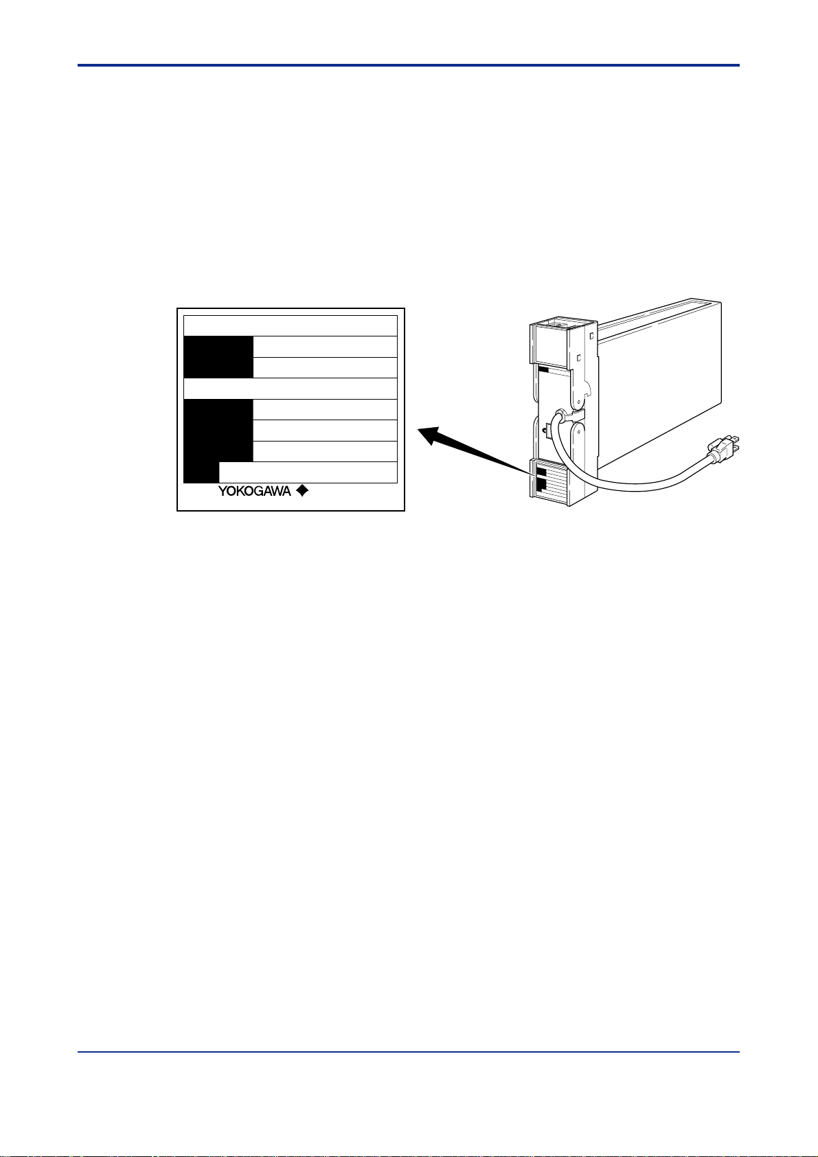
■ Check of Model and Suffix Codes
The model and suffix codes are indicated on the Name plate attached to the front cover of
the instrument. Crosscheck this information with the model and suffix codes of Section 2.2
to ensure that the product is as specified in the order .
DISTRIBUTOR
MODEL
SUFFIX
SDBT
-110*R
1-2
SUPPLY
INPUT
80–138V AC 47–63Hz
/20–130V DC
4 - 20mA DC
NO.
Made in Japan
Yokogawa Electric Corporation
Figure 1-1 Name plate for Loop Isolation T ype
■ Confirmation of the Package Contents
Check the package contents against the list below . If anything is missing or damaged,
immediately contact the sales office from which you purchased the product or your nearest
Y okogawa representative.
● SDBT Distributor.................................................................................................1
● Fuse (Parts No. : S9510VK)................................................................................1
● Instruction Manual (This manual)........................................................................1
F0101.EPS
IM 01B04T01-02E 12th Edition : 2004.05.01-00All Rights Reserved, Copyright© 2001, Y okogawa Electric Corporation
Page 7

<T oc> < 1. INTRODUCTION >
1.2 Documentation Conventions
This manual uses the following notational conventions.
■ Symbols
The following symbols are used in this manual.
WARNING
Indicates that operating the hardware or software in a particular manner may damage it or
result in a system failure.
NOTE
Draws attention to information that is essential for understanding the operation and/or
features of the product.
TIP
Gives additional information to complement the present topic and/or describe terms specific to this document.
1-3
Gives reference locations for further information on the topic.
■ Description of Displays
Some of the representations of product displays shown in this manual may be exaggerated
, simplified, or partially omitted for reasons of convenience when explaining them.
1.3 Notice
■ This Instruction Manual
● This manual should be passed on to the end user . Keep at least one extra copy of the
manual in a safe place.
● Read this manual carefully to gain a thorough understanding of how to operate this
product before you start using it.
● This manual is intended to describe the functions of this product. Yokogawa Electric
Corporation (hereinafter simply referred to as Yokogawa) does not guarantee that these
functions are suited to the particular purpose of the user .
● Under absolutely no circumstances may the contents of this manual, in part or in whole,
be transcribed or copied without permission.
See Also
● The contents of this manual are subject to change without prior notice.
● Every effort has been made to ensure accuracy in the preparation of this manual.
Should any errors or omissions come to your attention however , please contact your
nearest Yokogawa representative or our sales office.
IM 01B04T01-02E 12th Edition : 2004.05.01-00All Rights Reserved, Copyright© 2001, Y okogawa Electric Corporation
Page 8

<T oc> < 1. INTRODUCTION >
■ Protection, Safety, and Prohibition against Unauthorized Modification
● In order to protect the product and the system controlled by it against damage and
ensure its safe use, make certain that all of the instructions and precautions relating to
safety contained in this document are strictly adhered to. Yokogawa does not
guarantee safety if products are not handled according to these instructions.
● The following safety symbols are used on the product and in this manual.
CAUTION
If this symbol is indicated on the product, the operator should refer to the explanation given
in the instruction manual in order to avoid personal injury or death to either themselves or
other personnel, and/or damage to the instrument. The manual describes that the operator
should exercise special care to avoid shock or other dangers that may result in injury or
loss of life.
Protective ground terminal:
This symbol indicates that the terminal must be connected to ground prior to operating the
equipment.
1-4
Function ground terminal:
This symbol indicates that the terminal must be connected to ground prior to operating the
equipment.
AC voltage:
This symbol indicates that AC voltage is present.
DC voltage:
This symbol indicates that DC voltage is present.
● Do not turn off the power of the product during adjustment.
● Be sure to confirm the parameters referring to ‘‘5.4 Parameter List’ ’ before installing the
product in a system or plant. After confirming them, install the product in a system or
plant and turn on the power.
● If protection/safety circuits are to be used for the product or the system controlled by it,
they should be externally installed on the product.
● When you replace the parts or consumables of the product, only use those specified by
Yokogawa.
● Do not modify the product.
■ Force Majeure
● Yokogawa does not make any warranties regarding the product except those
mentioned in the WARRANTY that is provided separately.
● Yokogawa assumes no liability to any party for any loss or damage, direct or
indirect, caused by the use or any unpredictable defect of the product.
IM 01B04T01-02E 12th Edition : 2004.05.01-00All Rights Reserved, Copyright© 2001, Y okogawa Electric Corporation
Page 9
<T oc> < 2. GENERAL >
2. GENERAL
The SDBT distributor is designed to supply operating power to two-wire type transmitter
and convert 4 to 20 mA DC current signals from this transmitter into output signals.
The SDBT distributor has Loop isolation type (SDBT -11 type) and Filed isolation type
(SDBT-21 type). The SDBT -11 prepares two 1 to 5 V DC output signals, and SDBT-21
prepares one 4 to 20 mA DC output signal in addition to two 1 to 5 V DC output signals. The
SDBT-11 and SDBT-21 have built-in current limiters allowing normal operation even when
a short-circuit occurs on the transmitter side.
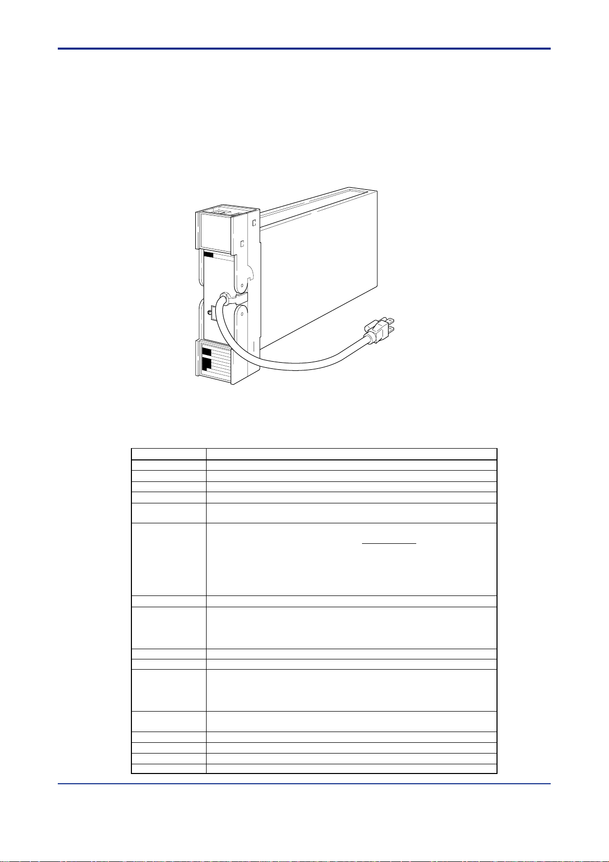
2-1
Figure 2-1 External View
2.1 Standard Specifications
Item Description
Trasmitter Used Operates on nominal 24 V DC, outputs 4 to 20 mA DC signal, 2-wire transmitter.
Number of Unit 1
Number of Output 2 points for SDBT-11, and 3 points for SDBT-21
Output Signal 1 to 5 V DC and 4 to 20 mA DC (for SDBT-21 only)
Load Resistance • 1 to 5 V DC output load resistance: at least 2k Ω
• 4 to 20 mA DC output load resistance: up to 750 Ω
Lead wire resistance Calculate from the following equation.
between transmitters
Low cut Characteristic Output is proportional to input when input is below 1 %
Isolation type (1) Loop isolation type Not isolated between input and output
(2) Filed isolation type Isolated between input and output
Accuracy ± 0.2 % of span (± 0.5 % of span for version with square root characteristic)
Transmitter Supply 25.0 to 25.5 V DC
Power Supply AC or DC (No change to instrument) 100 V version DC: 20 to130 V(polarity reversible)
Power Consumption • SDBT-11 type: 24 V DC 60 mA, 100 V AC 5.4 VA, 220 V AC 8.4 VA
• SDBT-21 type:24 V DC 115 mA, 100 V AC 9.5 VA, 220 V AC 12.4 VA
Ambient Temperature 0 to 50°C
Ambient Humidity 5 to 90% R.H. (non-condensing)
Mounting Indoor, rack mounting
Weight 1.7 kg
Lead wire Resistance(Ω) =
Note*: Minimum supply voltage – Maximum no-load voltage drop
E : Voltage drop when safety barrier is connected
T
E : Maximum voltage drop of transmitter
B
Isolated between input/output and power supply
Isolated between input/output and power supply
F0201.EPS
( 20* – E – E ) V
TB
0.02 A
AC: 80 to138 V, 47 to 63 Hz
220 V version DC: 120 to 340 V(polarity reversible)
AC: 138 to 264 V, 47 to 63 Hz
T0201.EPS
IM 01B04T01-02E 12th Edition : 2004.05.01-00All Rights Reserved, Copyright© 2001, Y okogawa Electric Corporation
Page 10
<T oc> < 2. GENERAL >
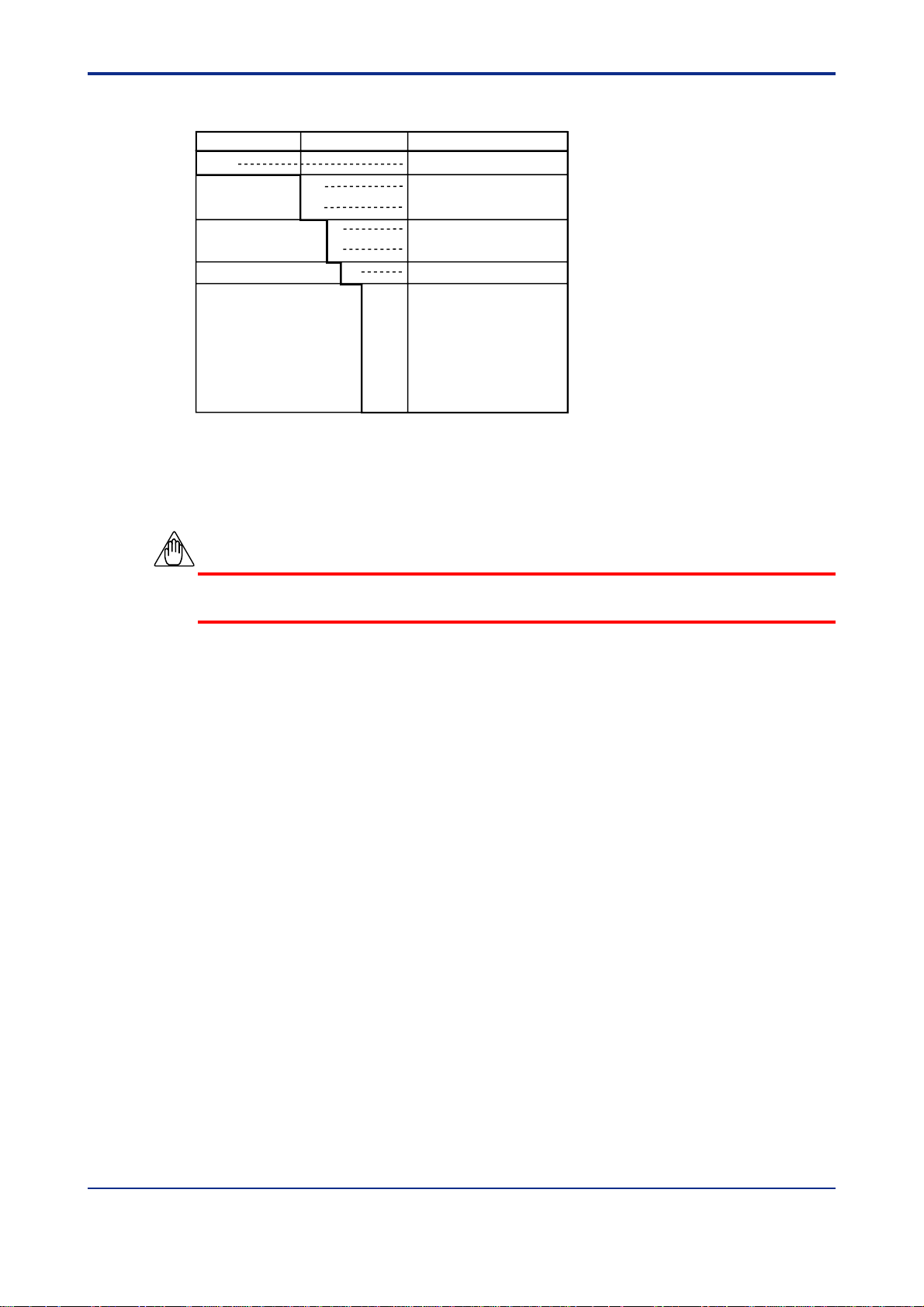
2.2 Model and Suffix Codes
Model Suffix Codes Description
SDBT Distributor
Isolation and -11 Loop isolation type, 1 point
Number of Input -21 Field isolation type, 1 point
Square Root Function 0 Not provided
1 Provided (for SDBT-21)
Style Code *R Style R
Option /A2ER 220 V power supply
/NHR Without case
/TB Power supply terminal
/FBP Power supply fuse bypass
/WSW With spring washers
/LOCK With special lock
2.3 Accessory
Fuse 1 A: 1
2-2
NOTE
The fuse (S9510VK) is the dedicated fuse. Do not use it for other products.
IM 01B04T01-02E 12th Edition : 2004.05.01-00All Rights Reserved, Copyright© 2001, Y okogawa Electric Corporation
Page 11
<T oc> < 3. INST ALLA TION >
3. INST ALLA TION
For details of the installation procedure and wiring precautions, refer to the technical
information “YEWSERIES 80 Installation Manual” (TI 1B4A9-01E) or the instruction
manual “Installation of Rack-Mounted Instruments” (IM 1B4F2-01E).
3.1 External Wiring
(a) T o prepare cables for connection to each terminal, install crimp-on solderless lugs for
4 mm screw on the end of each cable.
(b) Draw the internal unit out from the rack case.
(c) Connect the cables to the correct terminals referring to Table 3-1.
(d) Replace the internal unit into the rack case after completing the wiring.
(e) Always replace the terminal cover after completing the wiring.
NOTE
3-1
The terminal cover cannot be replaced if the internal unit is not installed in the rack case.
The terminal cover should be securely replaced because it has the function of locking the
internal unit.
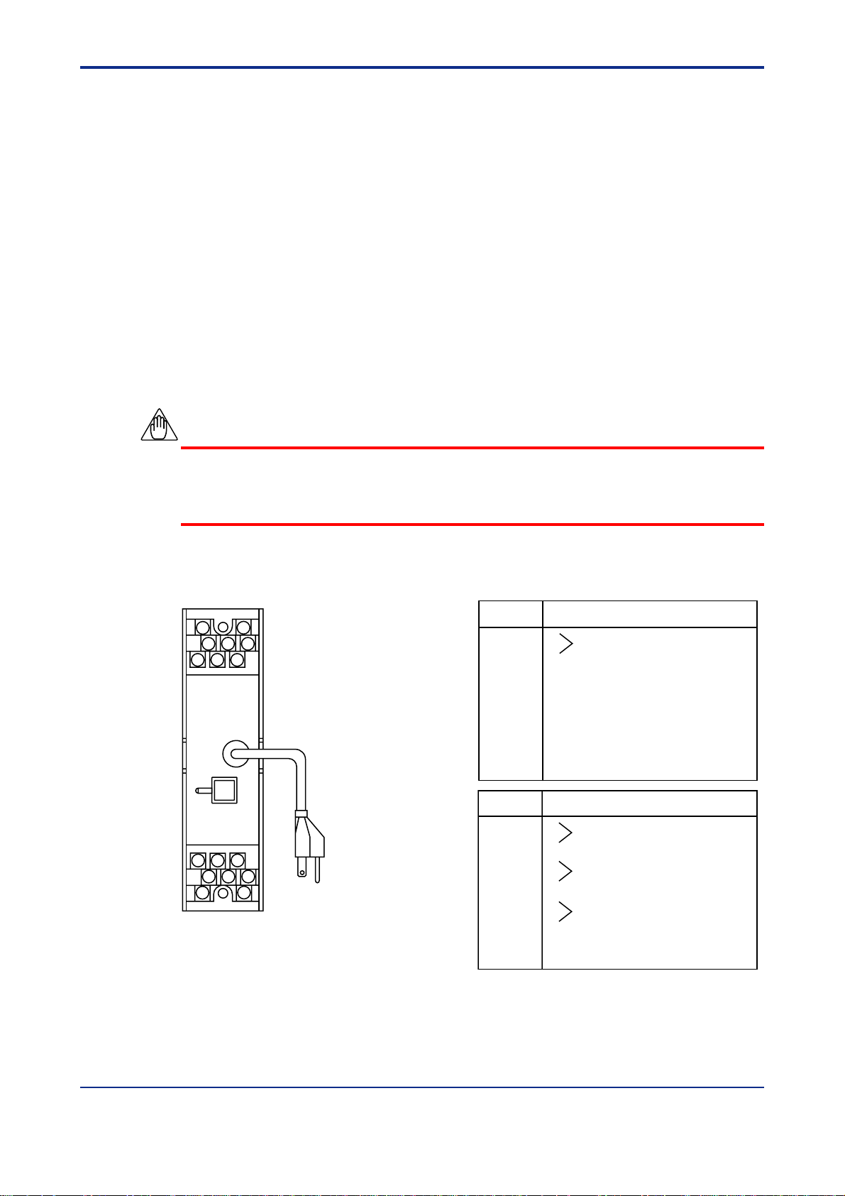
Table 3-1 Terminal Wiring
Terminal
Description
JK
HDB
ACF
531
642
78
F0301.EPS
Figure 3-1 T erminal Layout
Designation
1 +
2 –
3
4
5
6
7 COM (Note1)
8
Terminal
Description
Designation
A +
B –
C +
D –
F +
H –
J
K
Note1: When safety barrier is connected.
Note2: For SDBT-21 type only. When not used, terminals
remain opened.
Transmitter (Input)
Output 1 (1 to 5 V DC)
Output 3 (4 to 20 mA DC) Note2
Output 2 (1 to 5 V DC)
IM 01B04T01-02E 12th Edition : 2004.05.01-00All Rights Reserved, Copyright© 2001, Y okogawa Electric Corporation
Page 12

<T oc> < 3. INST ALLA TION >
3.2 Applicable Cables
(1) Signal circuit wiring
• Cross-sectional area of the cable conductor: 0.5 to 0.75 mm
• Examples of applicable cables: Single core PVC insulated flexible cable (VSF)
stranded wires (JIS C 3306); heat-resistant vinyl insulated cable (UL style 1007)
• Solderless lugs: All cable ends must be furnished with crimp-on
solderless lugs for 4 mm screw .
(2) Power supply wiring
• Cross-sectional area of the cable conductor: 1.25 to 2.00 mm
• Examples of applicable cables: 600 V PVC insulated cable (1 V) stranded wires (JIS
C 3307);PVC insulated cable for electrical apparatus
(KIV) stranded wires (JIS C 3316)
• Solderless lugs: All cable ends must be furnished with crimp-on
solderless lugs for 4 mm screw . The cable used
should fulfill the amperage requirement of each
instrument, and should also be small in voltage
drop.
2
2
3-2
IM 01B04T01-02E 12th Edition : 2004.05.01-00All Rights Reserved, Copyright© 2001, Y okogawa Electric Corporation
Page 13
<T oc> < 4. PRINCIPLES OF OPERATION >
4. PRINCIPLES OF OPERA TION
4.1 Loop Isolation T ype (for SDBT -1 1 Type)
The SDBT-11 supplies 25.0 to 25.5 V DC to two-wire transmitter through a current limiter,
and receives 4 to 20 mA DC current signals. The current signals are converted into 1 to 5 V
DC signals, then are output through output amplifier .
4-1
+
4 to 20 mA DC
–
Two-wire Transmitter
Current Limiter
1
2
7
250Ω
+
–
Power
Supply
Circuit
+
–
Figure 4-1 Functional Block Diagram for Loop Isolation T ype
+
A
Output 1 (1 to 5 V DC)
–
B
L+
Supply
N–
GND
+
F
Output 2 (1 to 5 V DC)
–
H
F0401.EPS
IM 01B04T01-02E 12th Edition : 2004.05.01-00All Rights Reserved, Copyright© 2001, Y okogawa Electric Corporation
Page 14

<T oc> < 4. PRINCIPLES OF OPERATION >
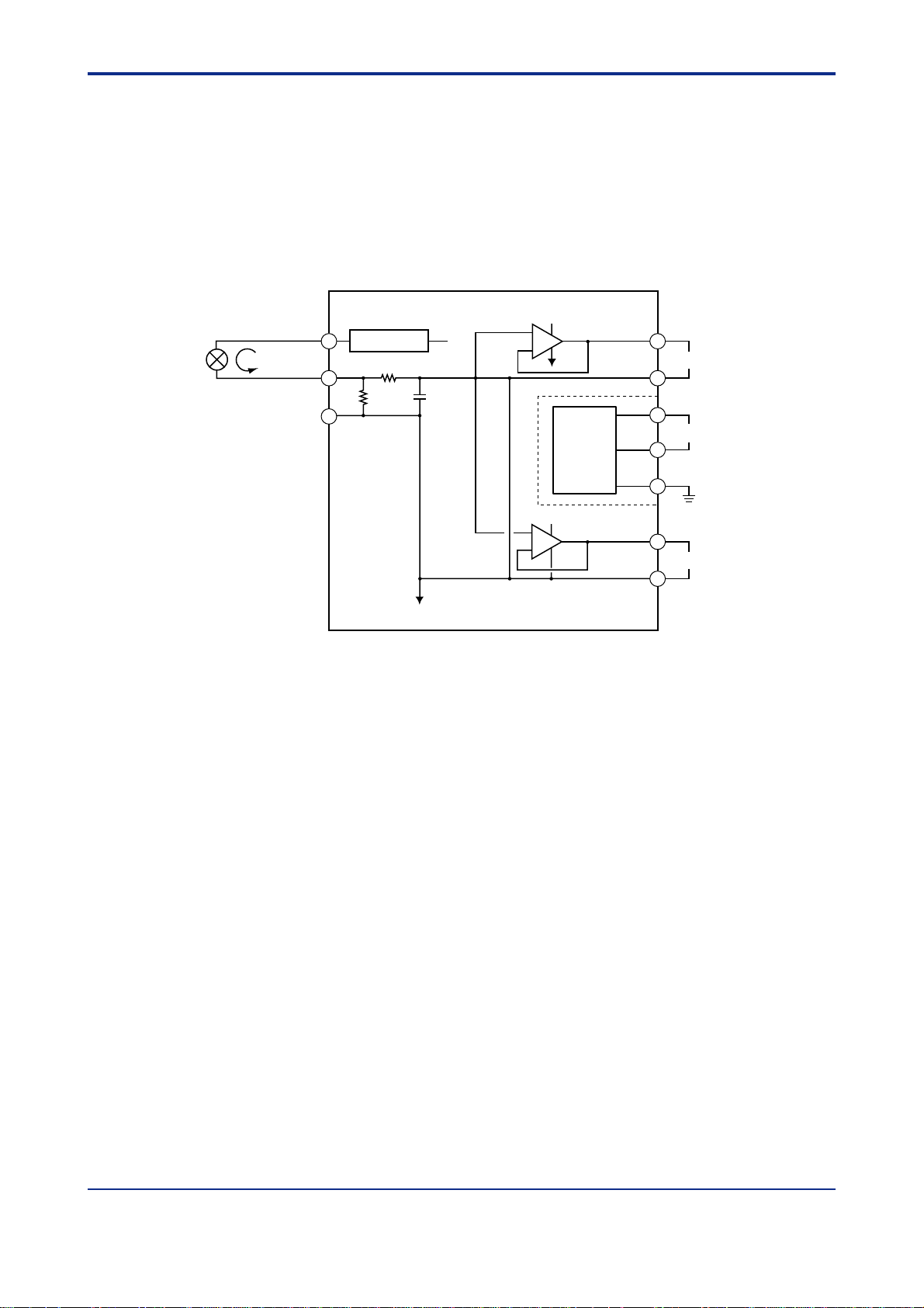
4.2 Filed Isolation T ype (for SDBT -21 Type)
The SDBT-21 supplies 25.0 to 25.5 V DC to two-wire transmitter through a current limiter,
and receives 4 to 20 mA DC current signals. The current signals are converted into 1 to 5 V
DC signals, then are converted into digital data in A/D conversion circuit.
The digital data has signal processing (square root characteristic etc.) in microprocessor to
be Pulse Width Modulation (PWM), then is coverted into 1 to 5 V DC or 4 to 20 mA DC
signals in output circuit through optical-isolation circuit.
Isolation Circuit
+
4 to 20 mA DC
–
Two-wire Transmitter
Handy
Terminal
1
2
7
Current Limiter
250Ω
A/D
Conversion
Circuit
Micro-
processor
Output
Circuit
Power
Supply
Circuit
+
A
Output 1 (1 to 5 V DC)
–
B
L+
Supply
N–
GND
4-2
Isolation Circuit
Figure 4-2 Functional Block Diagram for Field Isolation T ype
Output
Circuit
V/I
+
F
Output 2 (1 to 5 V DC)
–
H
+
C
Output 3 (4 to 20 mA DC)
–
D
F0402.EPS
IM 01B04T01-02E 12th Edition : 2004.05.01-00All Rights Reserved, Copyright© 2001, Y okogawa Electric Corporation
Page 15

<T oc> < 5. SETTING >
5. SETTING
The SDBT distributor is made ready for operation by simply turning on the power once the
installation and wiring are completed. The distributor does not require parameter settings
and the like if there is no change in the specifications at order .
5.1 Names of Components
Tag plate
BRAIN connector
(No connector for
SDBT-110 type)
5-1
Rack case
Name plate
Output terminal block
Main board
Terminal cover and handle for
drawing out the internal unit
Input terminal block
Multi-pin connector
Two-pole plug with earthing contact
Figure 5-1 Names of Components
F0501.EPS
IM 01B04T01-02E 12th Edition : 2004.05.01-00All Rights Reserved, Copyright© 2001, Y okogawa Electric Corporation
Page 16

<T oc> < 5. SETTING >
Position and function of setting jumper
5.2 Setting Jumper (for SDBT -21 T ype)
This instrument has the following setting jumper:
• Parameter Write Protect (JP2): ON/OFF
5.2.1 Check of Setting Jumper and Its Position
Setting jumper is on the main board of the internal unit.
Check the setting jumper in the following procedure.
(a) Pull forward the terminal cover, and draw the internal unit out from the rack case.
(b) Check that the jumper on the main board of the internal unit is set to obtain the desired
action.
(c) Use the tweezers to change the position of jumper.
(d) Put the internal unit back into the rack case.
(e) Replace the terminal cover.
Position and function of setting jumper
Parameter
write protect
(W.P.)
ON
Setting jumper (factory-set default)
5-2
OFF
ON:
Parameter change
by Handy Terminal
is prohibited.
Figure 5-2 Function and Set Point of Jumper
JP2
F0502.EPS
IM 01B04T01-02E 12th Edition : 2004.05.01-00All Rights Reserved, Copyright© 2001, Y okogawa Electric Corporation
Page 17

<T oc> < 5. SETTING >
5.3 Setting of Parameters (for SDBT -21 T ype)
This instrument has BRAIN communication parameters for specifying functions and
adjusting input. Connect JHT200 Handy T erminal (Note1) to the instrument to display or set parameters.
Note 1: BT200 BRAIN Terminal of YOKOGAWA ELECTRIC Corporation can also be used.
NOTE
For details of operation and adjusting procedures of JHT200 Handy Terminal, refer to the
instruction manual ‘‘JHT200 Handy Terminal’’ (IM JF81-02E).
<Connection>
Cable of 5-pin
connector type
JHT200
(F9182EE)
Handy Terminal
BRAIN connector
5-3
Figure 5-3 Connection
5.3.1 Configuration of Parameters
BRAIN communication parameters consist of the following parameters.
• Display (A & B parameters)
• Settings of Input and output (D parameters)
• Adjustment (P parameters)
• Test (Q parameters)
Adapter for modular jack
(E9786WH)
IM 01B04T01-02E 12th Edition : 2004.05.01-00All Rights Reserved, Copyright© 2001, Y okogawa Electric Corporation
Page 18

<T oc> < 5. SETTING >
5.3.2 Description of Parameters
The description of main parameters is as follows.
● Input/output-related parameters
(1) D21: LINEARIZE1 (for SDBT -21 1 T ype)
Sets the available/unavailable of square-root characteristic.
(2) D23: LOW CUT1 (for SDBT-211 T ype)
Sets the low cut point.
The input signal and output signal are shown in the figure below.
Output Signal (Y)
Y = X
Low cut point
5-4
0
Hysteresis (fixed to 0.2 %)
Input Signal (X)
(3) D33: OUT1 DR and D34: OUT2 DR
Sets the action direction for output 1 and output 2.
● Adjustment-related parameters
(1) P03: ZERO ADJ1
Performs Zero adjustment of input.
(2) P04: SP AN ADJ1
Performs Span adjustment of input.
(3) P13: OUT1 0% (Note1)
Adjusts 0% of output 1.
(4) P14: OUT1 100% (Note1)
Adjusts 100% of output 1.
(5) P15: OUT2 0% (Note1)
Adjusts 0% of output 2.
(6) P16: OUT2 100% (Note1)
Adjusts 100% of output 2.
● Test-related parameters
(1) Q02: OUT1 TEST (Note1)
Outputs the set value forcibly regardless of input condition.
Q03 has the same function.
Note1: After completing adjustment and test, press the [F4] (OK) key of the Handy Termi-
nal to return to normal condition (release of forced output).
IM 01B04T01-02E 12th Edition : 2004.05.01-00All Rights Reserved, Copyright© 2001, Y okogawa Electric Corporation
Page 19

<T oc> < 5. SETTING >
5.4 Parameter List (for SDBT -21 T ype)
BRAIN communication parameters for SDBT -21 type are as follows.
No. Symbol Parameter Name Setting Range Unit Default Setting Type
01 MODEL Model Name –––– unfixed Display
02 TAG NO Tag Number –––– unfixed Display
03 SELF CHK Self Check GOOD/ERROR –––– unfixed Display
<Display Parameters>
A DISPLAY1 Menu Name
A01 INPUT1 Input Display mA unfixed Display
A09 OUTPUT1 Output1 Display % unfixed Display
A10 OUTPUT2 Output2 Display % unfixed Display
A54 STATUS Status Display (Note1) 0000 to FFFF –––– unfixed Display
A55 WRT PROTECT Parameter Write Protect ON/OFF –––– OFF Display
A56 REV NO Revision number –––– unfixed Display
A58 MENU REV Menu Revision number –––– unfixed Display
A60 SELF CHK Self Check GOOD/ERROR –––– unfixed Display
B DISPLAY2 Menu Name
B01 INPUT1 Input Display mA unfixed Display
B09 OUTPUT1 Output1 Display % unfixed Display
B10 OUTPUT2 Output2 Display % unfixed Display
B60 SELF CHK Self Check GOOD/ERROR –––– unfixed Display
<Setting Parameters>
D SET(I/O) Menu Name
D01 TAG NO.1 Tag Number1 Up to 8-single-byte –––– unfixed Alphanumeric
D02 TAG NO.2 Tag Number2 Up to 8-single-byte –––– unfixed Alphanumeric
D03 COMMENT1 Comment1 Up to 8-single-byte –––– unfixed Alphanumeric
D04 COMMENT2 Comment2 Up to 8-single-byte –––– unfixed Alphanumeric
D21 LINEARIZE1 Linearize (Note2) OFF/SQR –––– SQR Selection
D22 LOW CUT1 Low Cut (Note2) 0.3 to 100.0 % 1.0 Real Number
D33 OUT1 DR Output1 Direction DIRECT/REVERSE –––– DIRECT Selection
D34 OUT2 DR Output2 Direction DIRECT/REVERSE –––– DIRECT Selection
D60 SELF CHK Self Check GOOD/ERROR –––– unfixed Display
<Adjustment Parameters>
P ADJUST Menu Name
P03 ZERO ADJ1 Zero Adjustment Note3 00.00 Selection
P04 SPAN ADJ1 Span Adjustment Note3 00.00 Selection
P13 OUT1 0% Output1 0% -20.0 to 20.0 % 00.00 Real Number
P14 OUT1 100% Output1 100% -20.0 to 20.0 % 00.00 Real Number
P15 OUT2 0% Output2 0% -20.0 to 20.0 % 00.00 Real Number
P16 OUT2 100% Output2 100% -20.0 to 20.0 % 00.00 Real Number
P60 SELF CHK Self Check GOOD/ERROR –––– unfixed Display
<Test Parameters>
Q TEST Menu Name
Q02 OUT1 TEST Output1 Test -25.0 to 125.0 % 000.0 Real Number
Q03 OUT2 TEST Output2 Test -25.0 to 125.0 % 000.0 Real Number
Q60 SELF CHK Self Check GOOD/ERROR –––– unfixed Display
Note 1: The condition of the instrument is displayed.
Note 2: Not displayed for SDBT-210 type.
Note 3: mA RST/mA INC/mA HINC/mA HDEC/mA DEC
5-5
IM 01B04T01-02E 12th Edition : 2004.05.01-00All Rights Reserved, Copyright© 2001, Y okogawa Electric Corporation
Page 20

Blank Page
Page 21

<T oc> < 6.
6. MAINTENANCE
This chapter describes the calibration procedures and part replacements that can be
done in the instrument room or service shop.
6.1 T est Equipment
For efficient maintenance of this distributor , it is recommended that the user have the
following test equipment manufactured by Yokogawa or their equivalent.
● DC V oltage/Current Standard, Type 7651…….........…........…........ 1 set
● Digital Voltmeter, Type 7562 …………………….................................1 set
● Calibration Booster , T ype JY0690 ……………………........................1 set
● Precision Resistor , Z9229FG………………...................................…1 unit
(250 Ω ± 0.05 % for current check)
6.2 Adjustment (for SDBT -21 T ype)
MAINTENANCE
>
6-1
NOTE
• For details of operation and adjusting procedures of JHT200 Handy Terminal, refer to the
instruction manual ‘‘JHT200 Handy T erminal’’ (IM JF81-02E).
• Do not turn off the power of the instrument during adjustment.
Adjust SDBT -21 type using JHT200 Handy T erminal.
(a) Connect the equipment as illustrated in Figure 6-2.
(b) Set the Parameter Write Protect (W .P.) of setting jumper to OFF. (Refer to ‘‘5.2 Setting
Jumper’’.)
(c) Turn on the power, and allow the equipment to warm up for about 5 minutes under this
condition.
(d) Connect JHT200 Handy Terminal.
<Connection>
Cable of 5-pin
connector type
JHT200
(F9182EE)
Handy Terminal
BRAIN connector
Figure 6-1 Connection
Adapter for modular jack
(E9786WH)
IM 01B04T01-02E 12th Edition : 2004.05.01-00All Rights Reserved, Copyright© 2001, Y okogawa Electric Corporation
Page 22

<T oc> < 6.
(e) Call the adjustment item (P: ADJUST) .
(f) P03: ZERO ADJ1 is displayed.
(g) Apply an input equivalent to 0 % of the input range. Check the input value and the input
display of P03: ZERO ADJ1. If the input value does not correspond to the display value ,
select P03: ZERO ADJ1 to enter the adjustment mode. Mainly select INC (addition) or
DEC (subtraction) for adjustment. (Selecting RST resets the adjusted value and re trieves the factory-set default.) Selecting HINC or HDEC performs adjustment using a
value ten times as large as INC or DEC.
(h) Apply an input equivalent to 100 % of the input range. Check the input value and the in put display of P04: SP AN ADJ1. If the input value does not correspond to the display
value, select P04: SP AN ADJ1 to enter the adjustment mode. Mainly select INC (addi tion) or DEC (subtraction) for adjustment. (Selecting RST resets the adjusted value and
retrieves the factory-set default.) Selecting HINC or HDEC performs adjustment using a
value ten times as large as INC or DEC.
(i) After completing the adjustment, set the parameter write protect (W.P.) of setting jumper
to ON. (Refer to ‘‘5.2 Setting Jumper’’.)
Table 6-1 Inpu/Output Characteristic Table
Input
%
0 4 mA 1 ± 0.008 V 1.000 ± 0.02 V
25 8 mA 2 ± 0.008 V 3.000 ± 0.02 V
50 12 mA 3 ± 0.008 V 3.828 ± 0.02 V
75 16 mA 4 ± 0.008 V 4.464 ± 0.02 V
100 20 mA 5 ± 0.008 V 5.000 ± 0.02 V
Without square root
characterisitic
Output
With square root
characterisitic
T0601.EPS
MAINTENANCE
>
6-2
YOKOGAWA Type 7651
or equivalent
DC Voltage/Current
Standard
Figure 6-2 Adjustment
YOKOGAWA Type 7562
or equivalent
Digtal Voltmeter
Digital Voltmeter
Note: The broken line shows
4 to 20 mA DC output
test circuit.
Calibration booster exclusively
for calibration
+
1
2
(Type JY0690)
–
–
+
–
+
250 Ω ± 0.05 %
3
4
5
JK
BDH
ACF
135
642
78
YOKOGAWA Type 7562
or equivalent
–
Digtal Voltmeter
+
Power Supply
F0602.EPS
IM 01B04T01-02E 12th Edition : 2004.05.01-00All Rights Reserved, Copyright© 2001, Y okogawa Electric Corporation
Page 23

<T oc> < 6.
6.3 Replacement of Fuse
When the fuse blows or requires replacement, replace it according to the following procedure. Recommended replacement interval: About 3 years.
NOTE
• When the fuse below , first check for the case because the fuse itself may not be
responsible for the problem. Then change the fuse.
• Use the dedicatd fuse (S9510VK). Do not use a fuse for other products.
(1) T o remove the fuse holder cap, then pull the fuse out in the direction shown in Figure 6
-3.
(2) When installing a new fuse, use a fuse with the correct rating. Fasten the cap se-
curely.
MAINTENANCE
>
6-3
Fuse
Rating: 1A
[ ]
Parts No.: S9510VK
Figure 6-3 Replacement of Fuse
6.4 Replacement of Capacitor
Degradation of the aluminum electrolytic capacitor used in the power supply unit depends
on operating temperature condition or operating environment.
Recommended replacement interval: 5 to 10 years.
F0603.EPS
NOTE
Ask your nearest Yokogawa sales staff for replacing the capacitor.
Do not replace the capacitor by yourself, because the parts number of power supply unit
(refer to CMPL 01B04T01-02E) and capacitor to be used are different according to the
power supply specifications.
IM 01B04T01-02E 12th Edition : 2004.05.01-00All Rights Reserved, Copyright© 2001, Y okogawa Electric Corporation
Page 24

Blank Page
Page 25

<Toc> < 7. TROUBLESHOOTING >
7. TROUBLESHOOTING
If any fault occurs in the instrument, note the symptoms, and follow Section 7-1
T roubleshooting Flowchart. T o find the fault, first wire the instruments according to
Figure 6-2, apply an input signal, and note the symptoms.
If the fault is difficult to find, contact your nearest Yokogawa sales staff.
7.1 T roubleshooting Flowchart
Instrument operates
abnormally.
7-1
Is output lower
than 0% ?
No
Is output higher
than 100% ?
No
Is
input/output accuracy
abnormal ?
No
Recheck instrument
abnormality.
YES
YES
YES
Is fuse blown ?
No
Is SDBT filed
isolated type ?
No
Replace main board
and recheck.
(See subsection 7.3.3)
Normal ?
No
YES
Replace fuse
and recheck.
YES
YES
End
(See section 6.3)
Perform zero and span.
(See section 6.2)
Normal ?
No
YES
End
Replace power supply
unit and recheck
Normal ?
Recheck instrument
abnormality.
Figure 7-1 Troubleshooting Flowchart
(See subsection 7.3.2)
YES
End
No
F0701.EPS
IM 01B04T01-02E 12th Edition : 2004.05.01-00All Rights Reserved, Copyright© 2001, Y okogawa Electric Corporation
Page 26
<Toc> < 7. TROUBLESHOOTING >
7.2 Action in Fault Condition
The output condition and error codes (BRAIN communication parameters) in fault
condition are shown in the table below.
NOTE
• ST ATUS is displayed in A54 of A: DISPLAY (display), and SELF CHK is displayed in 60 of
each item.
• ST ATUS error code is to be the addition display (hexadecimal number) when two errors or
more occur.
(Note1)
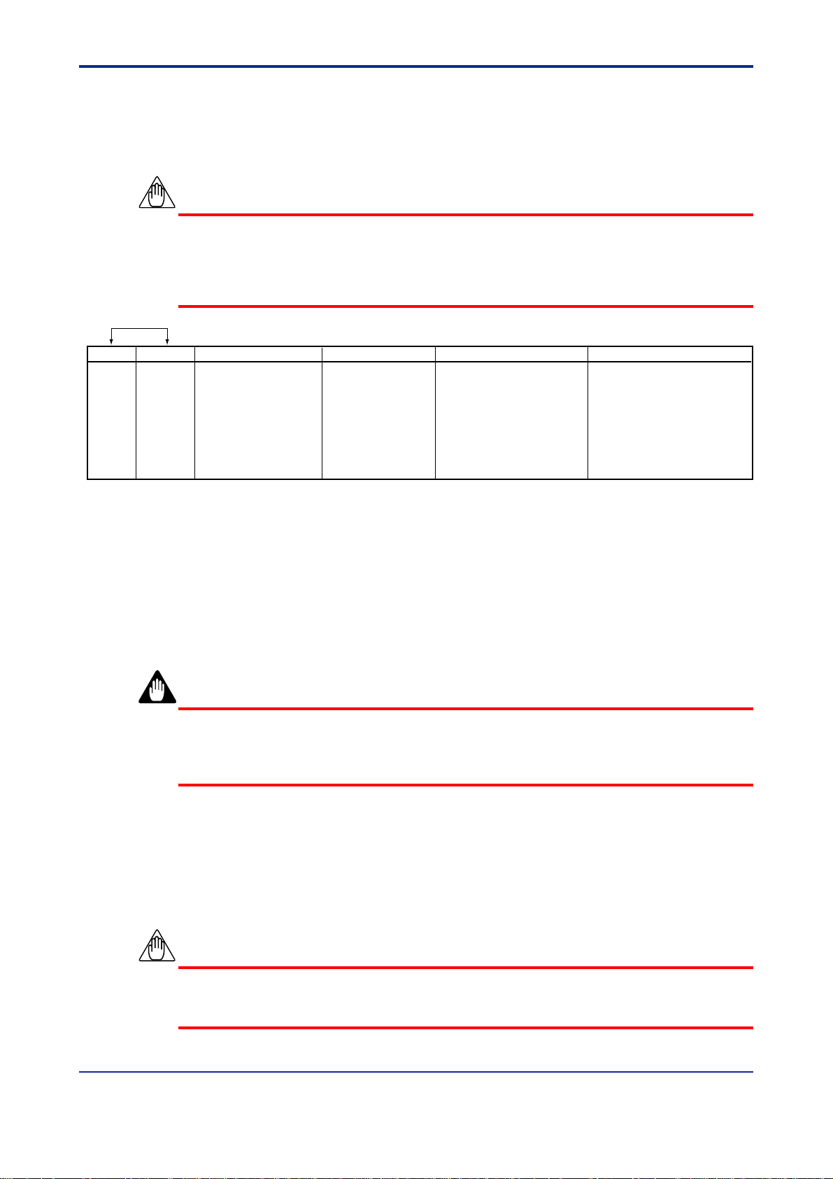
STATUS SELF CHK Error Information (Note2) Output Condition Description of Error Remedy
0001
0002
0004
0008
0040
Main board error, Power supply board error, and RAM error other than the errors mentioned above may occur.
Each output state of these errors is 0 % or less, and the error information can not be called using JHT200 Handy Terminal.
Note1: Displays for the BRAIN communication parameters, ■60: SELF CHK and A54: STATUS.
Note2: Displayed when calling ■60: SELF CHK.
Note3: Linear for the input below the low-cut point.
Note4: After checking the action, write ‘‘0’’ in STATUS to clear.
ERROR
ERROR
GOOD
ERROR
GOOD None Normal action Check power failure during Write ‘‘0’’ to clear.
EEPROM ERROR
EEPROM SUM ERROR
LOW_CUT
INPUT OVER RANGE
0 % or less EEPROM error Replace a main board.
0 % or less EEPROM sum check error Reset the parameter showing
an error. (Note4)
Normal action (Note3) Input below the square root Apply the input greater than the
characteristic with low-cut low-cut point.
Normal action Excessive input, out of -25 to Set the input within the range.
125 %
operation
7-2
T0701.EPS
7.3 Replacement of Parts
WARNING
Nobody except members of Yokogawa service staff is allowed to replace the parts.
Never replace the parts by yourself because there is a possibility of damage to the instrument or of danger .
7.3.1 Replacement Procedure
(1) Replacement of Power Supply Unit
(2) Replacement of Main Board
NOTE
• Disassemble only those parts that disassembly is required at parts replacement.
• Disassemble the instrument carefully .
IM 01B04T01-02E 12th Edition : 2004.05.01-00All Rights Reserved, Copyright© 2001, Y okogawa Electric Corporation
Page 27

<Toc> < 7. TROUBLESHOOTING >
7.3.2 Replacement of Power Supply Unit
(a) Pull the terminal cover (13) outward to draw the internal unit out from the rack case.
(b) Unplug the connector (1) from the power supply unit (2).
(c) Remove two screws (3) to separate the power supply unit (2) from the bracket (10).
NOTE
• Use the power supply unit for style R for replacement (refer to CMPL).
• The power supply unit of former style without compatibility can not be used.
7.3.3 Replacement of Main Board
(a) Remove the power supply unit (2).
(Refer to Subsection 7.3.2 for operating procedure.)
(b) Remove two screws (8) to separate the bracket (9).
(c) Remove four screws (4) to separate the bracket (10) and the front bracket (5) from
the main board (6).
7-3
Internal Unit
5
2
1
3
6
4
6
4
9
2
1
10
8
13
Figure 7-2 Disassemble View
IM 01B04T01-02E 12th Edition : 2004.05.01-00All Rights Reserved, Copyright© 2001, Y okogawa Electric Corporation
Page 28

Blank Page
Page 29
<T oc>
< Appendix /TB POWER SUPPLY TERMINALS for RACK-MOUNTED INSTRUMENTS (Option) >
Appendix / TB Power Supply T erminal
Connections for Rack-mounted
Instruments (Option)
Appendix-1 GENERAL
If you specify the terminal block to which the power source is directly connected (suffix
code /TB), the external wiring to the terminal block is necessary; therefore, drawing out of
the internal unit requires previous turning off of the power source and disconnection of the
wiring from the terminal block.
Appendix-2 APPLICABLE INSTRUMENTS
Model Description
STED mV, Temperature and Potentiometer/Voltage Converters
SKYD Alarm Unit
SALD Emf- and RTS- input Alarm Unit
SPLR Programmable Computing Unit
SIND Integrator
SISD Isolator
SDBT Distributor (for 1 point)
SDBS Distributor (for 4 points)
SDBU-21 Distributor (for single loop)
App.-1
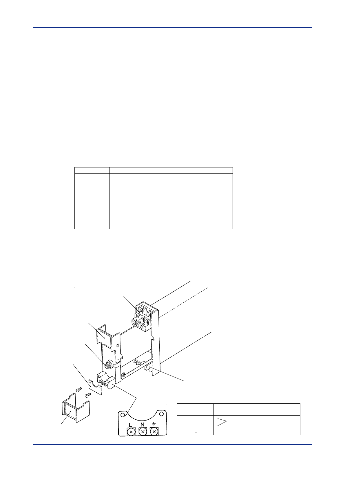
Appendix-3 EXTERNAL VIEW AND NAMES OF
COMPONENTS
Output Terminal Block
Outpul Terminal Cover
Power Fuse
Power Terminal Cover
Input Terminal Block
Power Terminal
Input Terminal Cover
Terminal
Designation
L AC or DC Power Supply
N (DC: polarity reversible)
Ground
Description
IM 01B04T01-02E 12th Edition : 2004.05.01-00All Rights Reserved, Copyright© 2001, Y okogawa Electric Corporation
Page 30

<T oc>
< Appendix /TB POWER SUPPLY TERMINALS for RACK-MOUNTED INSTRUMENTS (Option) >
App.-2
Appendix-4 POWER SUPPLY AND GROUND WIRING
(1) All cable ends must be furnished with crimp-on type solderless lugs (for 4 mm screw).
(2) Examples of applicable cables:
2
Cross-sectional area of the cable conductor: 2.0 mm
Applicable cable: 600 V vinyle insulated cable (IV) stranded wires, conforming to JIS
C3307.
Vinyle sheathed cables for electric appliances (KIV) stranded
wires, conforming to JIS C3316.
Note *: Power supply cables should be determined from the instrument power consumption-they must have
conductors with cross-sectional area of at least 1.25mm2.
(3) Wirings to power supply and ground terminals should be made after completion of
signal terminal wirings. (To facilitate connecting input signal, pull the internal unit
approximately half way out of the housing. Do not remove the power terminal block.)
(4) After completing the power supply and ground wiring, mount the power terminal cover.
. *
IM 01B04T01-02E 12th Edition : 2004.05.01-00All Rights Reserved, Copyright© 2001, Y okogawa Electric Corporation
Page 31
Customer
Maintenance
Parts List
Model SDBT (Style R)
Distributor
4
20
20
1
2
20
7
3
11
20
5
12
10
15
6
All Right Reserved, Copyright © 1983, Yokogawa Electric Corporation.
Subject to change without notice. Printed in Japan.
CMPL 01B04T01-02E
8th Edition: May 2004
Page 32

Qty
Model
SDBT-110
SDBT-210
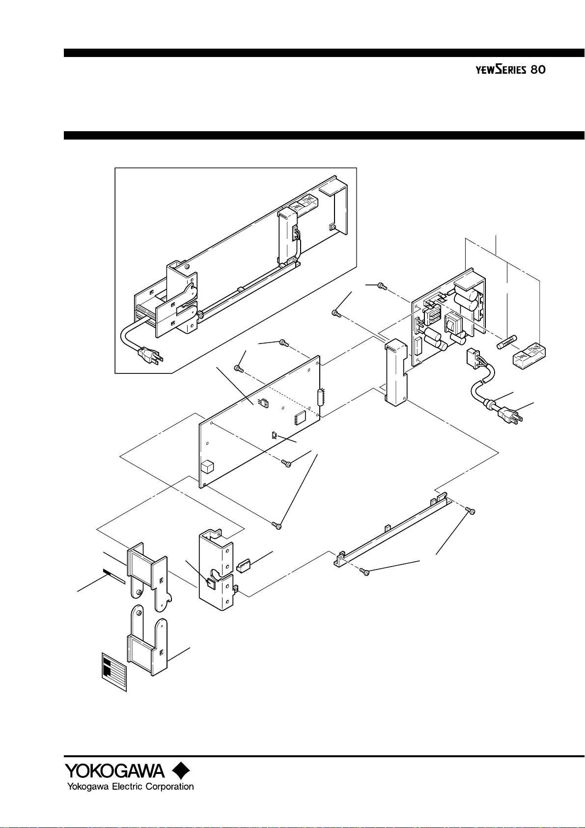
Item Part No. Description
1 L3040AA 1 Main Board Assembly
L3040AB 1 1 Main Board Assembly
2 A1211JS 1 1 1 1 Socket & Holder
3 L4040EA 1 1 1 1 Cap
4 L3040YA 1 1 1 1 Power Supply Unit (for 100V Version)
L3040YR 1 1 1 1 Power Supply Unit (for 220V Version)
5 S9510VK 1 1 1 1 Fuse(1A)
SDBT-211
2
6 E9713CA 1 1 1 1 Cover
7 E9713CK 1 1 1 1 Cover
10 E9713EG 1 1 1 1 Cable Assembly(for 100V Version)
E9713FS 1 1 1 1 Cable Assembly(for 220V Version)
11 E9713CE 1 1 1 1 Cover
12 S9079PB 1 1 1 1 Bushing
15 Y9422NP 1 1 1 1 Tag No. Label (blank)
20 Y9306JB 8 8 8 8 Pan H. Screw, M3x6
CMPL 01B04T01-02E 8th Edition : 2004.05.01-00
Page 33

Customer
4
8
76
3
1
2
5
Maintenance
Parts List
/TB
Power Supply Terminals
For Rack-Mounted Instruments
(Option)
All Right Reserved, Copyright © 1984, Yokogawa Electric Corporation.
Subject to change without notice. Printed in Japan.
CMPL 01B04F02-11E
8th Edition: May 2004
Page 34

Part No. Qty Descripion
Item
1
−−−
2
E9713CJ
3
−−−
4
E9713ET
5
S9510VK
6
E9713CV
7
Y9306JB
8
E9714DM
Table 1. Power Supply Unit Part Number.
Model
SPLR
STED, SISD, SDBT
SALD, SKYD, SIND, SDAU
SDBS, SDBU-21
SPCM
1
Power Supply Unit (see Table 1)
1
Cover
1
Bracket (see Table 2)
1
Terminal Assembly
1
Fuse (1A)
1
Cover
2
Pan H. Screw, M3 × 6
1
Label (1A/250V)
Power Supply Unit Part No.Applicable Instruments
100 V Version 200 V Version
E9715YH
L3040YH
L3040YJ
E9715YK
E9715YL
Table 2. Bracket Part Number.
Applicable Instruments
Model
STED-110/310/410
STED-210
STED-710
SISD,SIND-100/200, SDBT-21
SKYD-200/201/302
SKYD-100/101,SALD-110/310
SKYD-204/304
SKYD-104
SALD-210/710
SALD-724
SALD-214/714
SIND-104/204
SDBS
SDBT-11
SDAU-xxx/TB
SDAU-100/RLY4/TB
SDAU-270/RLY4/TB
SDAU-xxx/TB/COM
SDAU-100/RLY4/TB/COM
SDAU-270/RLY4/TB/COM
Bracket Part No.
L4040CA
L4040CB
L4040CC
L4040CE
L4040CG
L4040CH
L4040CL
L4040CM
L4040CQ
L4040CS
L4040CT
L4040CX
E9713DR
E9713DL
L4040DA
L4040DB
L4040DE
L4040DF
Page 35

<Int> <Toc> <Ind>
Revision Information
● Manual Title: Model SDBT (Style R) Distributor
● Manual No. : IM 01B04T01-02E
12th Edition/May 2004
Change of the company name.
i
Written by Yokogawa Electric Corporation
Published by Yokogawa Electric Corporation
2-9-32 Nakacho, Musashino-shi, Tokyo 180-8750, JAPAN
IM 01B04T01-02E
12th Edition : 2004.05.01-00
Page 36

Blank Page
Page 37

Page 38

YOKOGAWA ELECTRIC CORPORATION
Network Solutions Business Division
2-9-32, Nakacho, Musashino-shi, Tokyo, 180-8750 JAPAN
Phone: +81-422-52-7179 Facsimile: +81-422-52-6793
Sales Branch Offices
Tokyo, Nagoya, Osaka, Hiroshima, Fukuoka
YOKOGAWA CORPORATION OF AMERICA
Headquaters
2 Dart Road, Newnan, GA. 30265-1094 U.S.A.
Phone: +1-770-253-7000 Facsimile: +1-770-251-0928
Sales Branch Offices / Texas, Chicago, Detroit, San Jose
YOKOGAWA EUROPE B. V.
Headquaters
Databankweg 20, 3821 AL Amersfoort THE NETHERLANDS
Phone: +31-334-64-1611 Facsimile: +31-334-64-1610
Sales Branch Offices / Houten (The Netherlands), Wien (Austria), Zaventem
(Belgium), Ratingen (Germany), Madrid (Spain), Bratislava (Slovakia), Runcorn (United
Kingdom), Milano (Italy), Velizy villacoublay(France), Johannesburg(Republic of South
Africa)
YOKOGAWA AMERICA DO SUL S.A.
Headquarters & Plant
Praca Acapulco, 31-Santo Amaro, Sao Paulo/SP, BRAZIL CEP-04675-190
Phone: +55-11-5681-2400 Facsimile: +55-11-5681-4434
YOKOGAWA ENGINEERING ASIA PTE. LTD.
Head office
5 Bedok South Road, Singapore 469270 SINGAPORE
Phone: +65-6241-9933 Facsimile: +65-6241-2606
YOKOGAWA ELECTRIC KOREA CO., LTD.
Seoul Sales office
395-70, Shindaebang-dong, Dongjak-gu, Seoul,156-010, KOREA
Phone: +82-2-3284-3000 Facsimile: +82-2-3284-3019
YOKOGAWA TAIWAN CORPORATION
Head office
17F, No.39, Sec. 1, Chung Hwa Road Taipei, 100 TAIWAN
Phone: +886-2-2314-9166 Facsimile: +886-2-2314-9918
YOKOGAWA AUSTRALIA PTY. LTD.
Head office
Centrecourt D1, 25-27 Paul Street North, North Ryde, N. S. W. 2113, AUSTRALIA
Phone: +61-2-9805-0699 Facsimile: +61-2-9888-1844
YOKOGAWA INDIA LTD.
Head office
40/4 Lavelle Road, Bangalore, 560 001, INDIA
Phone: +91-80-227-1513 Facsimile: +91-80-227-4270
LTD. YOKOGAWA ELECTRIC
Grokholskiy per. 13, Build. 2, 4th Floor, 129010, Moscow, RUSSIA FEDERATION
Phone: +7-095-737-7868 Facsimile: +7-095-737-7869
 Loading...