

General
Specications
Model SDAU (Style R)
Digital Alarm Unit
GS 01B04K03-02E
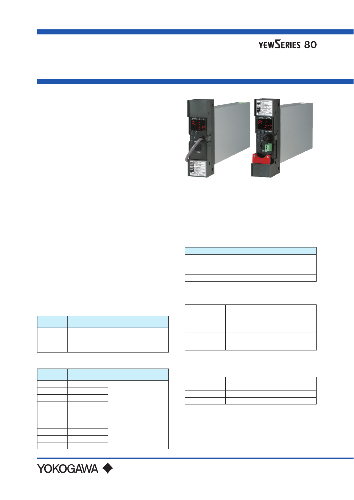
GENERAL
The SDAU Digital Alarm Unit accepts two input signals
(freely selectable from 1 to 5 V, mV, thermocouple
and RTD), and six detection results in alarm detecting
sections are freely connected to AND or to OR. Then
they are output to alarm relays (two points, or four
points for option).
Each alarm detecting section detects upper limit and
lower limit alarms of input absolute value, input rateof-change and 2-input deviation. Either a normally
energized or de-energized is selectable for alarm
output relays.
The display setter on the front panel can display input
values and set/change parameters such as an alarm
setpoint. A PC (VJ77) or the JHT200 Handy Terminal
can also set/ change parameters.
With the VJ77 Parameter Setting Tool you can do the
following:
· Read/write all parameters at once
·Savereadparameterstoale
· Copy parameters to other devices of the same model
andsuxcode.
*1: The BT200 BRAIN Terminal of YOKOGAWA
Electric Corporation can also be connected.
The adapter for modular jack (E9786WH) is
required for connecting a PC (VJ77) or the
JHT200 Handy Terminal or BT200 to the Digital
Alarm Unit.
INPUT/OUTPUT SIGNALS
Input Signals:
DCV Input
Input Signal
DC Voltage
Input
Measuring
Range
1 to 5 V DC Input Resistance: 1 MΩ
-50 to 150 mV DC
Input Resistance:1 MΩ
Input External Resistance:
Remarks
500 Ω or less
*1: ITS-90, JIS’95
*2: ASTM E988 Standard: W97Re3-W75Re25
(tungsten97% rhenium3%-tungsten75%
rhenium25%)
*3: ASTM E988 Standard: W95Re5-W74Re26
(tungsten95% rhenium5%-tungsten74%
rhenium26%)
RTD Input
Input Signal Measuring Range (°C)
JPt100 (JIS’89) -200.0 to 510.0 °C
Pt100 (ITS-90, JIS’97) -200.0 to 850.0 °C
Pt100 (IPTS-68, JIS’89) -200.0 to 660.0 °C
Pt50 (JIS’81) -200.0 to 649.0 °C
Input lead resistance : 10 Ω/lead or less
Number of Input Points
• Two points each 1 to 5 V DC (not
Two points
(SDAU-1 type)
Two points
(SDAU-2 type)
isolated between inputs mutually) or
• One point 1 to 5 V DC, and one point
mV, thermocouple or RTD (isolated
between inputs mutually)
Two points each universal inputs
(not isolated between inputs mutually)
mV, thermocouple or RTD freely selectable
Thermocouple Input
Input Signal
(*1)
Type K
(*1)
Type T
(*1)
Type J
(*1)
Type E
(*1)
Type B
(*1)
Type R
(*1)
Type S
(*1)
Type N
Type W3
Type W5
(*2)
(*3)
Measuring
Range(°C)
-270.0 to 1372.0
-270.0 to 400.0
-210.0 to 1200.0
-270.0 to 1000.0
100.0 to 1820.0
-50.0 to 1768.0
-50.0 to 1768.0
-270.0 to 1300.0
0 to 2315
0 to 2315
Remarks
Input Resistance:
1 MΩ
Input External Resistance:
500 Ω or less
Output Signals: Relay contact
Contact Capacity
100V AC 2A (Resistive load)
220V AC 0.5A (Resistive load)
30V DC 2A (Resistive load)
125V DC 0.5A (Resistive load)
Contact life expectancy: 600,000 times
GS 01B04K03-02E
7th Edition Jan. 2021

Number of Output Points:
Two sets of transfer contacts
Four sets of NC or NO contacts when
Alarm Output
Failure Output
Retransmission
Output
(Option)
/RLY4 option is selected.
Specify normally energized/normally de-
energized by parameter.
One set of NC or NO contact
Always normally energized
Not available when /RLY4, /VLT or /CUR
option is selected.
One point 1 to 5 V DC or 4 to 20 mA DC
/VLT: 1 to 5 V DC
/CUR: 4 to 20 mA DC
Failure output is not available.
Can not be combined with /RLY4
ALARM FUNCTIONS
Alarm Detecting Sections 3 (each independent)
Input Mode
Alarm Setting Upper and lower limit values, -19999 to 32000 (in engineering units)
Hysteresis 0 to 32000 (in engineering units)
Rate-of-Change Alarm
Sampling Time
Alarm Output Sections
(each independent)
Alarm Output Connection Six detection results are freely connected to AND or to OR.
Alarm Timer Mode
Timer Setting
Direction of Relay Action Set normally energized / de-energized.
Contact
Indicator Lamp Yellow lamp (ALMn) lights up on alarm.
Input absolute alarm
2-input deviation alarm
Input rate-of-change alarm
1 to 9999 s
2 or 4 when /RLY4 option is selected.
Alarm output (delay) timer
ON/OFF delay timer
Alarm output timer
Alarm ON/OFF delay
(dead time) timer
Two sets of transfer contacts or
Four sets of NC or NO contacts when /RLY4 option is selected.
0 to 600 s (in 1-second increment)
However, about a 0.2 second delay is added to the above set time to
prevent wrong operation.
0 to 999 s (in 1-second increment)
2
All Rights Reserved. Copyright © 2004, Yokogawa Electric Corporation
GS 01B04K03-02E Jan.12, 2021-00
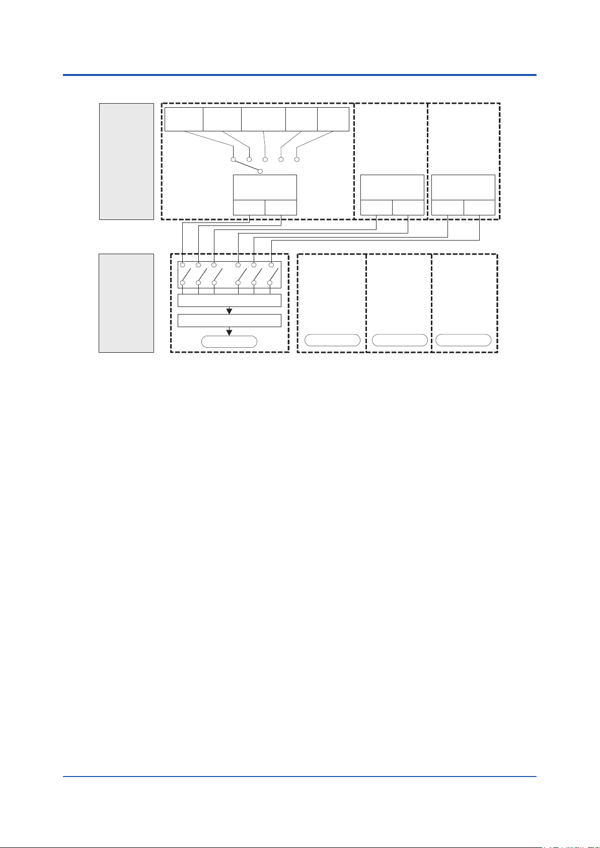
ALARM FUNCTION BLOCK DIAGRAM
Note 2: Any of six types of HI Alarm / LO Alarm can be connected.
F01.ai
3
PV1 PV2
Alarm
Detecting
Section
Alarm
Connection/
Output
Section
Note 1: Select one of them to use.
Deviation
(PV1-PV2)
(Note 1)
Alarm
Detection 1
HI Alarm LO Alarm
(Note 2)
AND/OR Connection
Alarm timer
Alarm Output 1
Rate-of-
change
PV1
Rate-of-
change
PV2
(Same as Alarm
(Same as Alarm
Detection 1)
Alarm
Detection 2
HI Alarm LO Alarm
HI Alarm LO Alarm
/RLY4
only
(Same as
Alarm Output 1)
Alarm Output 2 Alarm Output 3 Alarm Output 4
(Same as
Alarm Output 1)
Alarm Output 1)
Detection 1)
Alarm
Detection 3
/RLY4
only
(Same as
All Rights Reserved. Copyright © 2004, Yokogawa Electric Corporation
GS 01B04K03-02E Jan.12, 2021-00

4
MOUNTING AND APPEARANCE
Mounting: Mount on an indoor rack.
Signal Connection: M4 screw terminals
Power Supply Connection: Grounded two-pole plug,
or M4 screw terminals
External Dimensions: 180 x 48 x 300 (mm)
(Height x Width x Depth from the
mounting face)
Weight: Approx. 2 kg (including rack case)
DISPLAY FUNCTIONS
Display Setter: 5 digits, 2 lines, 11-segment LED
Indicator Lamps:
For all except /RLY4 option
Alarm status indication: ALM1,2 (yellow) 2
FAIL status indication: F (red) 1
Error indication: E (yellow) 1
For /RLY4 option
Alarm action indication: ALM1,2,3,4 (yellow) 4
Example of Display Data
Parameter Code Description
PVn Displays PVn
MODn Species input mode n
nH Sets upper-limit alarm nH
nL Sets lower-limit alarm nL
AN.OR.n Species AND/OR connection
n: Number of input point, number of alarm detection
In engineering units: -19999 to 32000
Decimal point position selectable
or number of alarm connection.
SETTING FUNCTIONS
Parameters can be set using the following three
ways.
(1) Display setter on the front panel
(2) VJ77 Parameters Setting Tool or JHT 200 Handy
Terminal
*1: The BT200 BRAIN Terminal of YOKOGAWA
(3) RS-485 Communication (when /COM option is
specied)
Key switches 4
(→ (SHIFT), ↑ (INCR), SET, )
Setting enable switch 1
(*1)
Electric Corporation can also be connected.
The adapter for modular jack (E9786WH) is
required for connecting a PC (VJ77), the JHT200
Handy Terminal or BT200 to the Digital Alarm
Unit.
NORMAL OPERATING CONDITIONS
Ambient
Temperature
Ambient
Humidity
Power
Supply
Voltage
0 to 50°C
5 to 90%RH (no condensation)
AC / DC both usage
100V version DC 20 to 130 V, no polarity
100V version AC
220V version DC
220V version AC
80 to 138 V,
47 to 63 Hz
120 to 340 V,
no polarity
138 to 264 V,
47 to 63 Hz
STANDARD PERFORMANCE
Performance in the standard operating condition (at
23°C±2°C, 50±10%RH)
Input Accuracy See the table: Input accuracy in page 4.
Alarm Action
Repeatability
Eect of ambient
temperature
Maximum
Current or Power
Consumption
Insulation
Resistance
Withstanding
Voltage
Burnout Time Within 60 s
Same as input accuracy
Twice of input accuracy / 10°C
240 mA for 24 V DC
17 VA for 100 V AC
22 VA for 220 V AC
Between I/O terminals and ground pin:
100 MΩ/500 V DC
Between power pins and ground pin:
100 MΩ/500 V DC
Between input terminal and ground pin:
500 V AC for 1 minute
Between output terminal, power pins and
ground pin:
1000 V AC for 1 minute (100 V version)
1500 V AC for 1 minute (220 V version)
All Rights Reserved. Copyright © 2004, Yokogawa Electric Corporation
GS 01B04K03-02E Jan.12, 2021-00

5
RECOVERY FROM POWER FAILURE
HOT Start: Continues the operation from the alarm
COLD Start: Power-on restart
* HOT start or COLD start is selectable by parameter.
Table: Input Accuracy
Input signal Accuracy
DCV input
T/C Accuracy (*
Type K
Type T
Type J
Type E
Type B
Type R
Type S
Type N
Type W3 0.0 to 2315.0 °C ±2.0 °C
Type W5 0.0 to 2315.0 °C ±2.0 °C
JPt100 (JIS’89) -200.0 to 510.0 °C
Pt100 (ITS-90,JIS’97) -200.0 to 850.0 °C
Pt100 (IPTS-68,JIS’89) -200.0 to 660.0 °C
Pt50 (JIS’81) -200.0 to 649.0 °C
(*1)
Note 1: Eect of ambient temperature:
Note 2: For thermocouple inputs except type B, add
Add the following (1) or (2), whichever is the larger:
(1) All types except types R and S: 0.5°C
Types R and S: 1°C
(2) Multiply the value in (1) by K, where
status immediately prior to power
failure.
(Hot start cannot be made for input
rate-of-change alarms. When the
alarm timer mode is set to alarm output
timer, ALM3 and ALM4 cannot be HOT
started.)
1 to 5V DC ±0.1%
-50.0 to 150.0mV DC ±20µV
1)
-270.0 to 0 .0 °C ±{0.5+A
0.0 to 1300.0 °C ±0.5 °C
1300.0 to 1372.0 °C ±1.0 °C
-270.0 to 0.0 °C ±{0.3+A
0.0 to 400.0 °C ±0.3 °C
-210.0 to 0.0 °C ±{0.3+A
0.0 to 1100.0 °C ±0.3 °C
1100.0 to 1200.0 °C ±1.0 °C
-270.0 to 0.0 °C ±{0.3+A
0.0 to 900.0 °C ±0.3 °C
900.0 to 1000.0 °C ±1.0 °C
100.0 to 600.0 °C ±{3.0+A
600.0 to 1820.0 °C ±3.0 °C
-50.0 to 0.0 °C ±4.0 °C
0.0 to 400.0 °C ±2.0 °C
400.0 to 1768.0 °C ±1.0 °C
-50.0 to 0.0 °C ±4.0 °C
0.0 to 400.0 °C ±2.0 °C
400.0 to 1768.0 °C ±1.0 °C
-270.0 to 0.0 °C ±{1.0+A
0.0 to 1300.0 °C ±1.0 °C
RTD Accuracy
±0.01%/°C of measuring range
the reference junction compensation error (see
below) to the accuracy above.
K=(Thermocouple output change/°C near normal
temperature) ÷ (Thermocouple output change
/°C near input temperature.)
(*2)
} °C
(*2)
} °C
(*2)
} °C
(*2)
} °C
(*3)
} °C
(*2)
} °C
±0.25°C
(*2)
For measured temperatures below 0 °C, add the
following A to the accuracy above.
- Measured temperature : -200 °C to below 0 °C
A = 0.0025 x | measured temperature |
- Measured temperature : below -200 °C
A = 0.1 x | measured temperature |
(*3)
For measured temperatures below 600 °C, add the
following B to the accuracy above.
- Measured temperature : 300 °C to below 600 °C
B = 0.02 x | measured temperature - 600 |
- Measured temperature : below 300 °C
B = 0.1 x | measured temperature - 300 | + 6
SELF-DIAGNOSTIC FUNCTIONS
F Lamp ON: CPU failure, A/D conversion failure,
E Lamp ON: Input signal overrange
*1: When more than 106.25%, or -6.25% or less of
input range upper limit (RH) and input range lower
limit (RL).
Failure Output: Failure contact output when F
EEPROM failure, EEPROM SUM
failure or RJC error
(*1)
, input
burnout, HOT start unavailable
lamp or E lamp lights up. However,
failure output action is in E lamp ON
selected by parameter. (Note: Only
when /CUR, /VLT or /RLY4 option is
not selected.)
CALIBRATION FUNCTIONS
Allow 0% and 100% points to be calibrated with an
accuracy of 1% or better when input signal is 1 to 5 V
by display setter on the front panel.
WIRING RESISTANCE CORRECTION
FUNCTIONS
If an error occurs because of input wiring resistance
when mV DC, thermocouple or RTD input, input
wiring resistance can be corrected.
OPTIONS
/A2ER: 220 V version with power supply plug
/TB/A2: 220 V version power supply terminal
/NHR: Without case
/FBP: Power supply fuse bypass
/LOCK: Power supply plug with lock
/WSW: With spring washer
/REK: Mount to same line with EK series rack
/TB: With power supply terminal
/VLT: With 1 to 5 V output
/CUR: With 4 to 20 mA output
/RLY4: Four points of alarm outputs
/COM: With RS-485 communication function
/BU: Burnout upscale
/BD: Burnout downscale
All Rights Reserved. Copyright © 2004, Yokogawa Electric Corporation
GS 01B04K03-02E Jan.12, 2021-00

COMMUNICATION FUNCTIONS
(/COM OPTION)
Input read and parameter read/write are possible.
Communication Interface: 1 channel
Standards: EIA RS-485
Communication System: 2-wire, half-duplex
Baud Rate: 1200, 2400, 4800 and 9600 bps
Communication Protocol: MODBUS, PC link, and
Ladder
Maximum Units Connectable: 31 units
Maximum Communication Distance: 1200 m
Communication cable: Shielded twisted-pair cables
(AWG24 or the equivalent)
for communication wiring
cables.
RETRANSMISSION OUTPUT
FUNCTIONS (/VLT and /CUR
OPTIONS)
/VLT: 1 to 5 V output of measured value or 2-input
deviation
/CUR: 4 to 20 mA output of measured value or
2-input deviation
6
Accuracy: ±0.1% of span
Load resistance:
2 kΩ or more
Accuracy: ±0.1% of span
Load resistance:
750 Ω or less
Retransmission
Output
Accuracy
(Option)
1 to 5 V DC
(/VLT)
4 to 20 mA
(/CUR)
Retransmission Output Accuracy Guaranteed Range:
mV Input
Span 10 to 100 mV DC
Three times
Zero
Elevation
the span, or
within ±50 mV,
whichever is the
smaller
Retransmission output accuracy guaranteed range is
within the range above and within 0.0% to 100.0%
of span.
Thermocouple
Input
10 to 63 mV
(converted
based on thermo
electromotive
force)
Three times
the span, or
within ±25 mV,
whichever is the
smaller
RTD Input
50 to 500°C
Within ve
times the
span
ACCESSORIES
Label sheet: 1 sheet
Reference junction bracket :
For SDAU-120-xx*R/NHR or
SDAU-270-xx*R/NHR
All Rights Reserved. Copyright © 2004, Yokogawa Electric Corporation
GS 01B04K03-02E Jan.12, 2021-00

MODEL AND SUFFIX CODES
Model Sux Codes Optional Sux Codes Description
SDAU Digital Alarm Unit
Input Signal 2
Input Signal 1
Always 0 0 Always 0
Auxiliary Codes
Available Combination
Standard Specications:
SDAU-100, SDAU-110
SDAU-120, SDAU-130
SDAU-270
Auxiliary Codes:
SDAU-100: -SV
SDAU-110: -MV
SDAU-120: from -TK to -TS
SDAU-130: from -PA to -PD
SDAU-270: -UN
Style Code *R Style R
Common Options
Note 1: /VLT, and /CUR options can be combined with only –UN auxiliary code.
/RLY4 option can be combined with only –SV or –UN auxiliary codes.
/VLT, /CUR and RLY4 options can not be combined with each other.
Note 2: For two points of 1 to 5 V inputs (-SV), burnout upscale or burnout downscale is not selectable.
Note 3: For universal inputs, 1 to 5 V is not selectable.
Note 4: Specify the option codes /TB and /A2 at the same time.
Note: There is no dierence between the latest and the previous temperature tables as far as applying them to the YEWSERIES.
- TC: Latest version; IEC60584-1: 2013/JIS C1602:2015
Previous version; IEC60584-1: 1995/JIS C1602:1995
- RTD Latest version; IEC60751- 2008/JIS C1604:2013
Previous version; IEC751- 1995/JIS C1604:1997
-1 Input signal 2: 1 to 5 V
-2 Input signal 2: Universal
0 1 to 5 V
1 mV
2 TC (Thermocouple)
3 RTD
7 Universal
(Note 3)
-SV Two points of 1 to 5 V inputs
-MV mV input
-TK Type K (ITS-90,JIS’95)
-TT Type T (ITS-90,JIS’95)
-TJ Type J (ITS-90,JIS’95)
-TE Type E (ITS-90,JIS’95)
-TB Type B (ITS-90,JIS’95)
-TR Type R (ITS-90,JIS’95)
-TS Type S (ITS-90,JIS’95)
-PA JPt 100 (JIS’89)
-PB Pt50 (JIS ’81)
-PD Pt100 (ITS-90, JIS’97)
-UN Universal (SDAU-270 only)
/A2ER 220 V version power supply plug
/TB/A2 220 V version power supply terminal
/NHR Without case
/FBP Power supply fuse bypass
/LOCK Power supply plug with lock
/WSW With spring washer
/REK Mount to same line with EK series rack
/TB With power supply terminal
/VLT With 1 to 5 V output
(Note 1)
/CUR With 4 to 20 mA output
/RLY4 Four points of alarm outputs
/COM With RS-485 communication function
/BU Burnout upscale
/BD Burnout downscale
(Note 2)
(Note 2)
(Note 1)
7
(Note 3)
(Note 3)
(Note 4)
(Note 1)
All Rights Reserved. Copyright © 2004, Yokogawa Electric Corporation
GS 01B04K03-02E Jan.12, 2021-00

ORDERING INSTRUCTIONS
F02.ai
F03.ai
1. Model, sux codes and auxiliary codes, and optional sux codes if necessary
2. SDAU-110, -120, -130: Upper limit of input range (RH1), lower limit of input range (RL1). Specify RH1 and RL1
within the measuring range of Input/output signal specications, where RL1<RH1.
Initial values
RH1 parameter; 100.0 when mV input, maximum value of measuring range when temperature input
RL1 parameter; 0.0 when mV input, minimum value of measuring range when temperature input
3. SDAU-270: Select the sensor type from the input signals in Input/Output Signals on Page 1. However, 1 to 5 V is
not selectable. Initial value: Pt100 (ITS90, JIS’97)
(Note: Sensor type is selectable for input 1 and input 2 respectively.)
TERMINAL CONNECTIONS
● Input/Output Terminals
8
6
Terminal
Designation
(*1)
Excluding /RLY4, /VLT and /CUR /RLY4 /VLT or /CUR
A
NC
B
COM
NC, NO
C
COM
D
NC
F
COM
H
J
NO
K
NO
1
2
3
4
5
6
7
8
*1: Terminal for connecting the reference junction bracket.
*2: Switch NC/NO using jumper.
+
-
+
-
NC: Relay normally closed contact (closed when relay de-energized).
NO: Relay normally open contact (open when relay de-energized).
Alarm output 1
(*2)
Failure output
Alarm output 2
1 to 5 V, mV, TC Input RTD Input
Input 1
Input 2
J K
B BDH
A
F
C
Refer to
External
Dimensions
1
5
3
4
2
8
7
● RS485 Communication Terminals (/COM Option)
NC, NO
COM
NC, NO
COM
NC, NO
COM
COM
NC, NO
Description
(*2)
(*2)
(*2)
(*2)
B+
A-
Alarm output 1
Alarm output 4
Alarm output 2
Alarm output 3
A
B
B
A
B
B
NC
COM
+
-
NC
COM
NO
NO
Input 1
Alarm output 1
Retransmission output
1 to 5 V or 4 to 20 mA
Alarm output 2
Input 2
All Rights Reserved. Copyright © 2004, Yokogawa Electric Corporation
COM
GS 01B04K03-02E Jan.12, 2021-00

<<Contents>> <<Index>>
Without/COM With/COM
F04.ai
Unit: mm
Without/COM With/COM
F05.ai
EXTERNAL DIMENSIONS
● Power Supply Plug Connection Type
9
9
180
Electric Electric
48
48 52 300
● Power Supply Terminal Type
Electric Electric
180
180
220V Power
supply plug
180
100V Power
supply plug
22 136
13622
48 48 71 300
All Rights Reserved. Copyright © 2004, Yokogawa Electric Corporation
Subject to change without notice.
Power supply terminals
GS 01B04K03-02E Jan.12, 2021-00
 Loading...