

Page 1

User’s
Manual
IM 01B04K03-02E
Model SDAU (Style R)
Digital Alarm Unit
IM 01B04K03-02E
8th Edition
Page 2

Page 3

Toc-1
IM 01B04K03-02E
8th Edition: Jan.29,2021-00
IM 01B04K03-02E 8th Edition
Model SDAU (Style R)
Digital Alarm Unit
CONTENTS
1. INTRODUCTION .................................................................................. 1-1
1.1 Inspection ............................................................................................. 1-2
1.2 Documentation Conventions ............................................................... 1-3
1.3 Notice .................................................................................................... 1-4
1.4 About Compatibility with the Conventional Model (Style E) ............. 1-6
2. GENERAL ............................................................................................. 2-1
2.1 Standard Specifications ....................................................................... 2-2
2.2 Model and Suffix Codes ............................................................................. 2-3
2.3 Accessory ...................................................................................................... 2-4
3. INSTALLATION .................................................................................... 3-1
3.1 External Wiring ..................................................................................... 3-1
4. FUNCTIONS ......................................................................................... 4-1
4.1 Operation Principle .............................................................................. 4-1
4.1.1 Hardware Block Diagram ........................................................... 4-1
4.2 Input Processing Function .................................................................. 4-3
4.3 Alarm Processing Function ................................................................. 4-5
4.3.1 Alarm-Detecting Sections .......................................................... 4-6
4.3.2 Alarm Connection / Output Sections .......................................... 4-7
4.3.3 Example of Setting the Alarm Functions .................................. 4-10
4.4 Retransmission Output Function (for /VLT and /CUR Options) ...... 4-11
4.5 Communication Function (for /COM Option) .................................... 4-12
4.6 Function of Recovery from Power Failure ........................................ 4-13
4.7 Self-Diagnostic Function ................................................................... 4-14
4.8 Alarm/Failure Outputs at Power-on and Power Failure .................... 4-15
5. SETTING ............................................................................................... 5-1
5.1 Names of Components ......................................................................... 5-3
5.2 Part Names of the Display Setter ......................................................... 5-4
5.3 Setting Jumpers ................................................................................... 5-6
5.3.1 Checking Setting Jumpers and their Locations ........................... 5-7
5.3.2 Change of Setting Jumper ......................................................... 5-8
5.4 Settings Done from the Front Panel of the Alarm Unit ....................... 5-9
5.4.1 How to Operate the Key Switches .............................................. 5-9
5.4.2 Settings Using Key Switches (Example) .................................. 5-10
Page 4

Toc-2
IM 01B04K03-02E
8th Edition: Jan.29,2021-00
5.5 Parameter Change Disable Function................................................. 5-11
5.6 Various Display Modes ...................................................................... 5-12
5.6.1 Display at Power ON ............................................................... 5-12
5.6.2 LOCK Display .......................................................................... 5-12
5.6.3 Display in Display Shutoff Mode .............................................. 5-12
5.6.4 Error Display ............................................................................ 5-13
5.6.5 Display of Self-Diagnostic Results ........................................... 5-13
5.6.6 Detailed Alarm Status Display .................................................. 5-14
5.7 Settings Using the JHT200 Handy Terminal ..................................... 5-16
5.8 Settings Using a PC (VJ77) ................................................................ 5-17
6. PARAMETERS ..................................................................................... 6-1
6.1 Configuration of Parameters ............................................................... 6-1
6.2 Display on Front Panel: Development View of Parameters ............... 6-2
6.3 Display on Front Panel: List of Parameters ........................................ 6-6
6.4 BRAIN Communication: List of Parameters ...................................... 6-22
7. MAINTENANCE ................................................................................... 7-1
7.1 Test Equipments ................................................................................... 7-1
7.2 Reference Table of Thermocouple and RTD ....................................... 7-1
7.3 Adjustment and Check ......................................................................... 7-1
7.3.1 Input Adjustment ........................................................................ 7-2
7.3.2 Correction of Input W iring Resistance ........................................ 7-4
7.4 Check of Reference Junction Temperature Compensation Action.... 7-6
7.5 List of Replaceable Parts ..................................................................... 7-7
8. TROUBLESHOOTING ........................................................................ 8-1
8.1 Actions under Fault Conditions .......................................................... 8-2
9. POWER SUPPLY TERMINAL CONNECTINS (Options /TB, /TB/A2
and /REK) ...................................................................................... 9-1
9.1 Names of Components and Power Terminal Symbols ....................... 9-2
9.2 Power Supply and Ground Wiring ...................................................... 9-3
General Specifications
Revision Information
Page 5

<1. INTRODUCTION >
1-1
IM 01B04K03-02E
8th Edition: Jan.29,2021-00
1. INTRODUCTION
This manual describes the functions and operations of the SDAU Digital Alarm
Unit.
Intended Readers
This manual is intended for personnel in charge of:
Installation and wiring
Instrumentation and setup of functions
Operation and monitoring of the controller
Maintenance of equipment
Related Documents
The following documents all relate to the SDAU Digital Alarm Unit. Read them as
necessary. The codes enclosed in parentheses are the document numbers.
• Rack-Mounted Instruments (IM 1B4F2-01E)
Describes mounting and wiring for YS80 rack-mounted instruments.
• Model VJ77 PC-based Parameters Setting Tool (IM 77J01J77-01E)
Describes operation of the VJ77 parameters setting tool.
• Model JHT200 Handy Terminal (IM 77J50H01-01EN)
Describes operation of JHT200.
• YS80*R Rack-Mounted Instruments Communication Functions
Describes the communication functions of SDAU. (IM 01B04F01-20E)
Page 6
<1. INTRODUCTION >
1-2
IM 01B04K03-02E
8th Edition: Jan.29,2021-00
1.1 Inspection
The SDAU digital alarm unit is shipped only after stringent inspection at the factory.
Visually inspect the product upon delivery to make sure it is not damaged in any way.
Store the box and inner packing material of the package in a safe place / they may be
needed if there is a problem with the product and it needs to be sent back for repair.
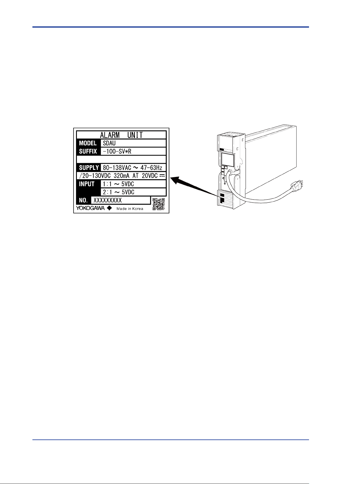
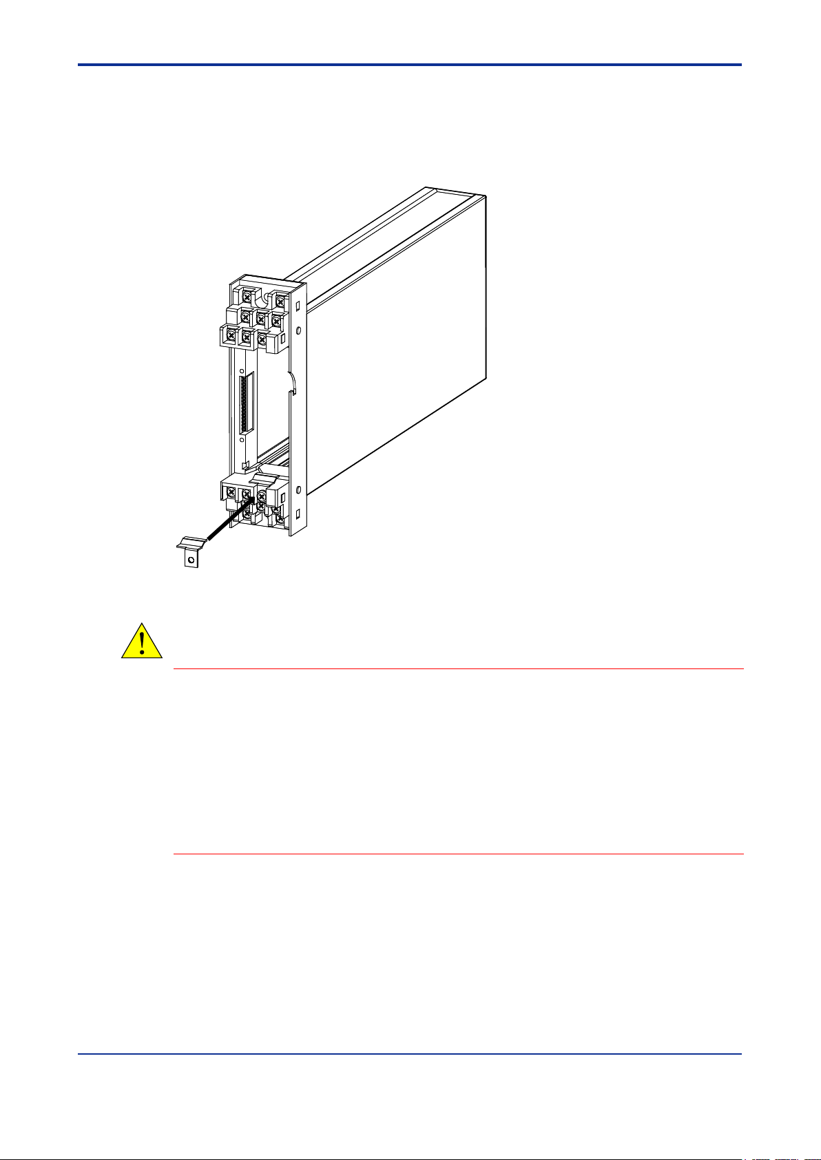
Check of Model and Suffix Codes
The model and suffix codes are indicated on the Name plate attached to the front cover
of the instrument. Crosscheck this information with the model and suffix codes of
Section 2.2 to ensure that the product is as specified in the order.
Figure1.1 Appearance and Name plate (Description example)
Confirmation of the Package Contents
Check the package contents against the list below. If anything is missing or damaged,
immediately contact the sales office from which you purchased the product or your
nearest Yokogawa representative.
• SDAU Digital Alarm Unit ................................................................................. 1
• Reference Junction Bracket (Parts No.: L4040EN)
(only for SDAU-120-xx*R/NHR or SDAU-270-xx*R/NHR) ............................. 1
• Alarm Label (Parts No.: L4040JA) .................................................................. 1 sheet
• Precautions on the Use of the YS80 Series.................................................... 1
Downloadable Electronic Manuals
You can download the latest manuals from the following website:
To view the User ’s Manuals, use Adobe Acrobat Reader of Adobe Systems Incorporated.
http://www.yokogawa.com/ns/ys/
Page 7
<1. INTRODUCTION >
1-3
IM 01B04K03-02E
8th Edition: Jan.29,2021-00
1.2 Documentation Conventions
This manual uses the following notational conventions.
Symbols
The following symbols are used in this manual.
Indicates that operating the hardware or software in a particular manner may damage it
or result in a system failure.
Draws attention to information that is essential for understanding the operation and/or
features of the product.
TIP
Gives additional information to complement the present topic and/or describes terms
specific to this document.
See Also
Gives reference locations for further information on the topic.
Description of Displays
Some of the representations of product displays shown in this manual may be
exaggerated, simplified, or partially omitted for reasons of convenience when explaining
them.
QR Code
The product has a QR Code pasted for efficient plant maintenance work and asset
information management. It enables confirming the specifications of purchased products
and user’s manuals.
For more details, please refer to the following URL.
https://www.yokogawa.com/qr-code
QR Code is a registered trademark of DENSO WAVE INCORPORATED.
Page 8

<1. INTRODUCTION >
1-4
IM 01B04K03-02E
8th Edition: Jan.29,2021-00
1.3 Notice
This User’s Manual
This manual should be passed on to the end user. Keep at least one extra copy of
the manual in a safe place.
Read this manual carefully to gain a thorough understanding of how to operate this
product before you start using it.
This manual is intended to describe the functions of this product. Yokogawa Electric
Corporation (hereinafter simply referred to as Yokogawa) does not guarantee that
these functions are suited to the particular purpose of the user.
Under absolutely no circumstances may the contents of this manual, in part or in
whole, be transcribed or copied without permission.
The contents of this manual are subject to change without prior notice.
Every effort has been made to ensure accuracy in the preparation of this manual.
Should any errors or omissions come to your attention however, please contact your
nearest Yokogawa representative or sales office.
Protection, Safety, and Prohibition against Unauthorized Modification
The following safety symbols are used on the product and in this manual.
If this symbol is indicated on the product, the operator should refer to the explanation
given in the user’s manual in order to avoid personal injury or death to either
themselves or other personnel, and/or damage to the instrument. The manual
describes that the operator should exercise special care to avoid shock or other
dangers that may result in injury or loss of life.
Protective ground terminal:
This symbol indicates that the terminal must be connected to ground prior to
operating the equipment.
Function ground terminal:
This symbol indicates that the terminal must be connected to ground prior to
operating the equipment.
AC voltage:
This symbol indicates that AC voltage is present.
DC voltage:
This symbol indicates that DC voltage is present.
Page 9

<1. INTRODUCTION >
1-5
IM 01B04K03-02E
8th Edition: Jan.29,2021-00
In order to protect the product and the system controlled by it against damage and
ensure its safe use, make certain that all of the instructions and precautions relating
to safety contained in this document are strictly adhered to. Yokogawa does not
guarantee safety if products are not handled according to these instructions.
If protection/safety circuits are to be used for the product or the system controlled by
it, they should be externally installed on the product.
Do not turn off the power of the product during adjustment.
When you replace the parts or consumables of the product, only use those specified
by Yokogawa.
Do not modify the product.
Force Majeure
Yokogawa does not make any warranties regarding the product except those
mentioned in the WARRANTY that is provided separately.
Yokogawa assumes no liability to any party for any loss or damage, direct or
indirect, caused by the use or any unpredictable defect of the product.
Page 10

<1. INTRODUCTION >
1-6
IM 01B04K03-02E
8th Edition: Jan.29,2021-00
1.4 About Compatibility with the Conventional
Model (Style E)
The operation and function differ from the conventional model.
Read this manual carefully to gain a thorough understanding of how to operate this
product before you start using it.
Be sure to confirm the parameters such as alarm set point and setting jumper
referring to ''6. PARAMETERS'' before installing the product in a system or plant.
After confirming them, install the product in a system or plant and turn on the power.
When replacing an internal unit with the old style code (SDAU-1xx-xx*E) with an
internal unit with the SDAU-120-xx*R or SDAU-270-UN*R style code, the reference
junction contact fitting (for contact with the RJC sensor) must be installed (or
replaced). For more information, see Section 2.3, “Accessory.”
Page 11
<2. GENERAL>
2-1
IM 01B04K03-02E
8th Edition: Jan.29,2021-00
2. GENERAL
The SDAU Digital Alarm Unit accepts two input signals (freely selectable from 1 to
5 V, mV, thermocouple, and RTD), and six detection results present in alarmdetecting sections are freely AND-connected or OR-connected. These results are
then output to alarm relays (two points, or four points if the optional suffix is
specified).
Each alarm-detecting section detects high limit and low limit alarms of an input
absolute value, input rate-of-change, and two-input deviation. Either a normally
energized or de-energized state is selectable for alarm output relays.
The digital display and key switches on the front panel allow input values to be
displayed and parameters such as alarm setpoints to be set or changed.
Parameters can also be set or changed by using a PC (VJ77) or the JHT200 Handy
Terminal
The self-diagnostic function also allows failure outputs to be generated.
With the VJ77 Parameter Setting Tool you can do the following:
*1: The B T200 BRAIN Term inal of Yokogawa E lectric Corporati on can also be connected.
Modular jack adapter (part no.: E9786WH) is requi red t o connect a PC (VJ77), the JHT200 Handy Termin al or BT200
*1
.
· Read/write all parameters at once
· Save read parameters to a file
· Copy parameters to other devices of the same model and suffix code.
to the Digital Alarm Unit.
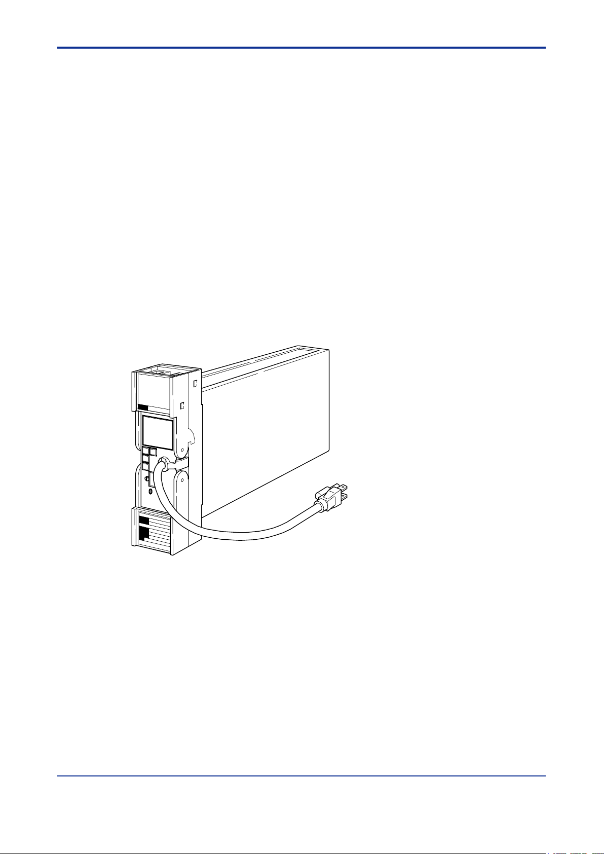
Figure 2.1 Appearance of the SDAU Digital Alarm Unit
Page 12

<2. GENERAL>
2-2
IM 01B04K03-02E
8th Edition: Jan.29,2021-00
2.1 Standard Specifications
Please see the General Specifications (GS 01B04K03-02E) at the end of this manual.
Page 13
<2. GENERAL>
2-3
IM 01B04K03-02E
8th Edition: Jan.29,2021-00
Model
Suf fix Codes
Optional Suf fix Codes
Description
SDAU
Digital Alarm Unit
-1 Input signal 2: 1 to 5 V
-2 Input signal 2: Universal (Note 3)
0
1 to 5 V
1
mV 2 TC (Thermoc ouple)
3
RTD 7 Universal (Note 3)
Always 0
0 Always 0
Auxiliary Codes
SDAU-270: -UN
-SV
Two points of 1 to 5 V inputs
-MV
mV input
-TK
Type K (ITS-90,JIS’95)
-TT
Type T (ITS-90,JIS’95)
-TJ
Type J (ITS-90,JIS’95)
-TE
Type E (ITS-90,JIS’95)
-TB
Type B (ITS-90,JIS’95)
-TR
Type R (ITS-90,JIS’95)
-TS
Type S (ITS-90,JIS’95)
-PA
JPt 100 (JIS’89)
-PB
Pt50 (JIS ’81)
-PD
Pt100 (ITS-90, JIS’97)
-UN
Universal (Note 3)
Style Code
*R Style R
/A2ER
220 V version power supply plug
/TB/A2
220 V version power supply terminal (Note 4)
/NHR
W ithout c ase
/FBP
Power supply fuse bypass
/LOCK
Power supply plug with lock
/WSW
With spring washer
/REK
Mount to same line with EK series rack
/TB
With power supply terminal
/VLT
With 1 to 5 V output (Note 1)
/CUR
With 4 to 20 mA output (Note 1)
/RLY4
Four points of alarm outputs (Note 1)
/COM
With RS-485 communication function
/BU
Burnout upscale ( Note 2)
/BD
Burnout downscale (Note 2)
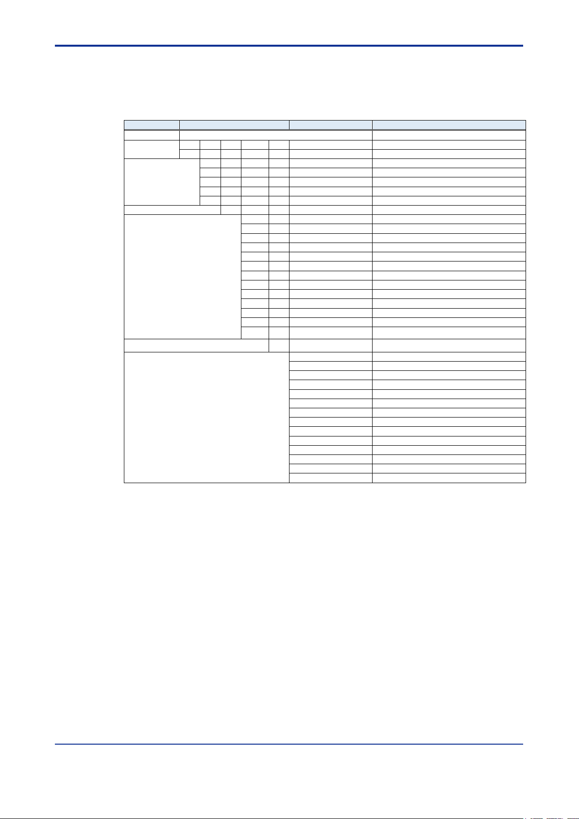
2.2 Model and Suffix Codes
The following table shows the SDAU model and suffix codes.
Table 2.1 Model and Suffix Codes
Input Signal 2
Input Signal 1
Available Combination
Standard Specifications:
SDAU-100, SDAU-110
SDAU-120, SDAU-130
SDAU-270
Auxiliary Codes:
SDAU-100: -SV
SDAU-110: -MV
SDAU-120: from -TK to -TS
SDAU-130: from -PA to -PD
Common Options
Note 1: /VLT, and /CUR options can be combined with only –UN auxiliary c ode.
/RLY4 option can be combined with only –SV or –UN auxiliary codes.
/VLT, /CUR and RLY4 options can not be combined with each other.
Note 2: For two points of 1 to 5 V inputs (-SV), burnout upscale or burnout downscale is not selectable.
Note 3: For universal inputs, 1 to 5 V is not selec table.
Note 4: Specify the option codes /TB and /A2 at th e same tim e.
Page 14
<2. GENERAL>
2-4
IM 01B04K03-02E
8th Edition: Jan.29,2021-00
2.3 Accessory
Reference junction bracket : 1
(For SDAU-120-xx*R/NHR or SDAU-270-xx*R/NHR)
Alarm label : 1
Figure 2.2 Location of the Reference Junction Bracket
CAUTION
• Notice when replacing the internal unit of a conventional model:
When replacing the internal unit of a conventional model (SDAU-1xx-xx*E) with that of SDAU-
120-xx*R or SDAU-270-UN*R, a reference junction bracket (for connection to the RJC sensor)
needs to be installed (replaced).
For SDAU-120-xx*E
Replace a reference junction bracket (for connection to the RJC sensor).
For models other than SDAU-120-xx*E
Install a reference junction bracket (for connection to the RJC sensor).
Page 15
<3. INSTALLATION>
3-1
IM 01B04K03-02E
8th Edition: Jan.29,2021-00
Alarm output 2
Alarm output 1
Failure output
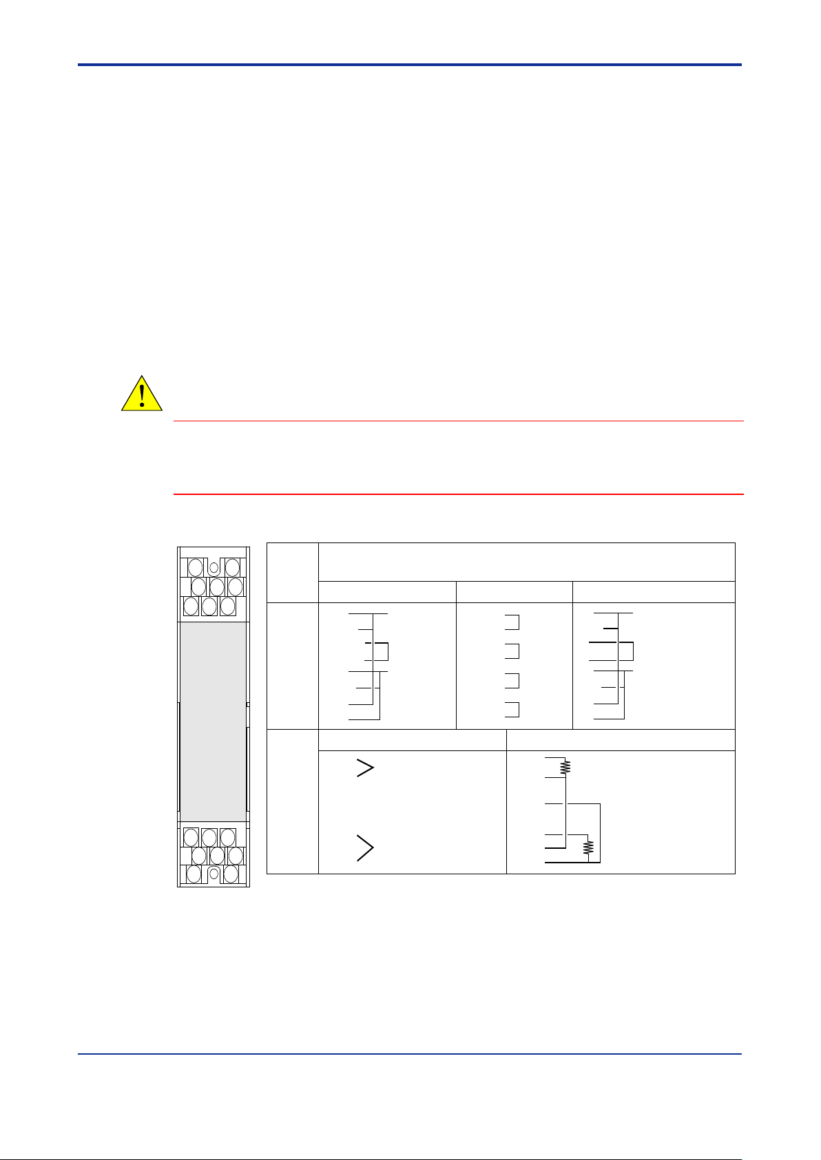
1 to 5 V, mV, TC Input RTD Input
*1: Terminal for connecting the reference junction bracket.
*2: Switch NC/NO using jumper.
NC: Relay normally closed contact (closed when relay de-energized).
NO: Relay normally open contact (open when relay de-energized).
Terminal
Designation
Description
Excluding /RLY4, /VLT and /CUR
/RLY4 /VLT or /CUR
Alarm output 1
Retransmission output
1 to 5 V or 4 to 20 mA
Alarm output 2
Alarm output 1
Alarm output 4
Alarm output 2
Alarm output 3
Input 1
Input 2
Input 1
Input 2
A
C
F
B
D
H
J
K
1
3
5
2
4
6
7
8
A
B
C
D
F
H
J
K
NC
COM
NC,NO
COM
NC
COM
NO
NO
NC,NO
COM
NC,NO
COM
NC,NO
COM
COM
NC,NO
NC
COM
+
-
NC
COM
NO
NO
1
2
3
4
5
6
7
8
+
-
+
-
A
B
B
A
B
B
(*1)
(*2)
(*2)
(*2)
(*2)
(*2)
Front view
may differ
according to
device.
3. INSTALLATION
For details of the installation procedure and wiring precautions, refer to the
instruction manual “Installation of Rack-Mounted Instruments” (IM 1B4F2-01E).
3.1 External Wiring
(a) All cable ends must be furnished with crimp-on type solderless lugs (for 4mm
screws).
(b) Draw out the internal unit from the rack case.
(c) Connect the cable to the correct terminals referring to Figure 3.1.
(d) Return the internal unit into the rack case after completing the wiring.
(e) Always return the terminal block cover to its original position after completing the
wiring.
CAUTION
The terminal block cover cannot be returned to its original position if the internal unit is not installed
correctly inside in the rack case. Securely return the terminal block cover because it also functions as
lock for the internal unit.
Figure 3.1 Terminal Layout and Terminal Wiring
Page 16

<3. INSTALLATION>
3-2
IM 01B04K03-02E
8th Edition: Jan.29,2021-00
B+
A-
COM
Figure 3.2 RS485 Communication Terminal Layout (/COM option)
Applicable Cables
(1) Signal circuit wiring
• Cross-sectional area of the cable conductor: 0.5 to 0.75 mm
• Examples of applicable cables: Single core PVC insulated flexible cable (VSF)
(2) Alarm circuit wiring
• Cross-sectional area of the cable conductor: 0.5 to 1.25 mm
• Examples of applicable cables: 600 V PVC insulated cable (IV) stranded wires (JIS
(3) Power supply wiring
• Cross-sectional area of the cable conductor: 1.25 to 2.00 mm
• Examples of applicable cables: 600 V PVC insulated cable (IV) stranded wires
2
stranded wires (JIS C 3306);
heat-resistant vinyl-insulated cable (UL style 1007)
2
C 3307);
PVC insulated cable for electric appliances (KIV)
stranded wires (JIS C 3316);
heat-resistant vinyl-insulated cable (UL style 1007)
2
(JIS C 3307)
Page 17
<4. FUNCTIONS >
4-1
IM 01B04K03-02E
8th Edition: Jan.29,2021-00
4. FUNCTIONS
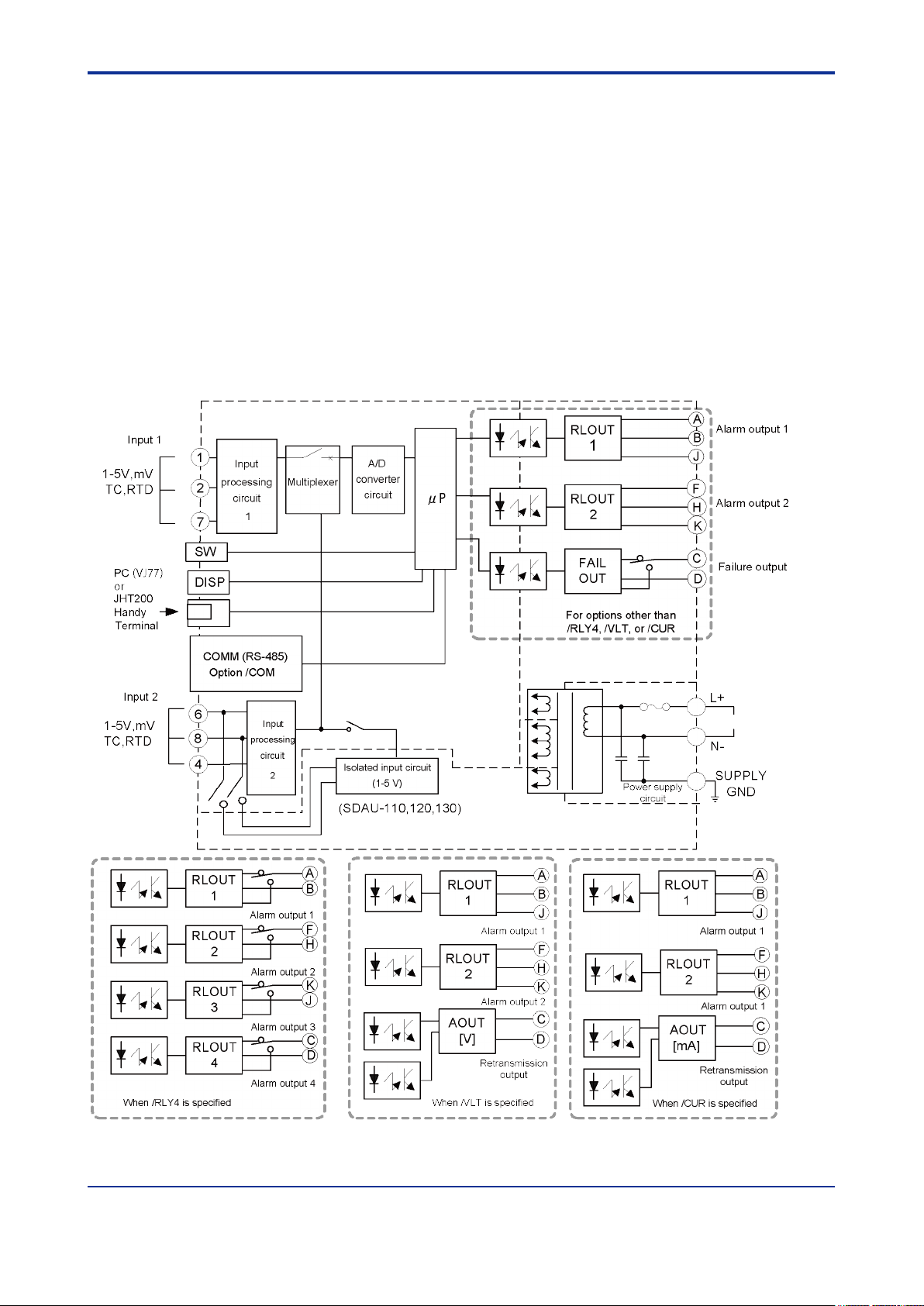
4.1 Operation Principle
Input signals are converted into digital data by an A/D converter circuit. This digital data
is signal processed (such as linearization or square root extraction) by a microprocessor
and then computed for alarm detection. Alarm relays are energized or de-energized
according to the alarm computation outputs.
For retransmission output, an input signal is pulse-width modulated after being signal
processed. It is then converted into 1 to 5 V DC or 4 to 20 mA DC signals via a photoisolation circuit.
4.1.1 Hardware Block Diagram
Figure 4.1 Hardware Block Diagram
Page 18
<4. FUNCTIONS >
4-2
IM 01B04K03-02E
8th Edition: Jan.29,2021-00
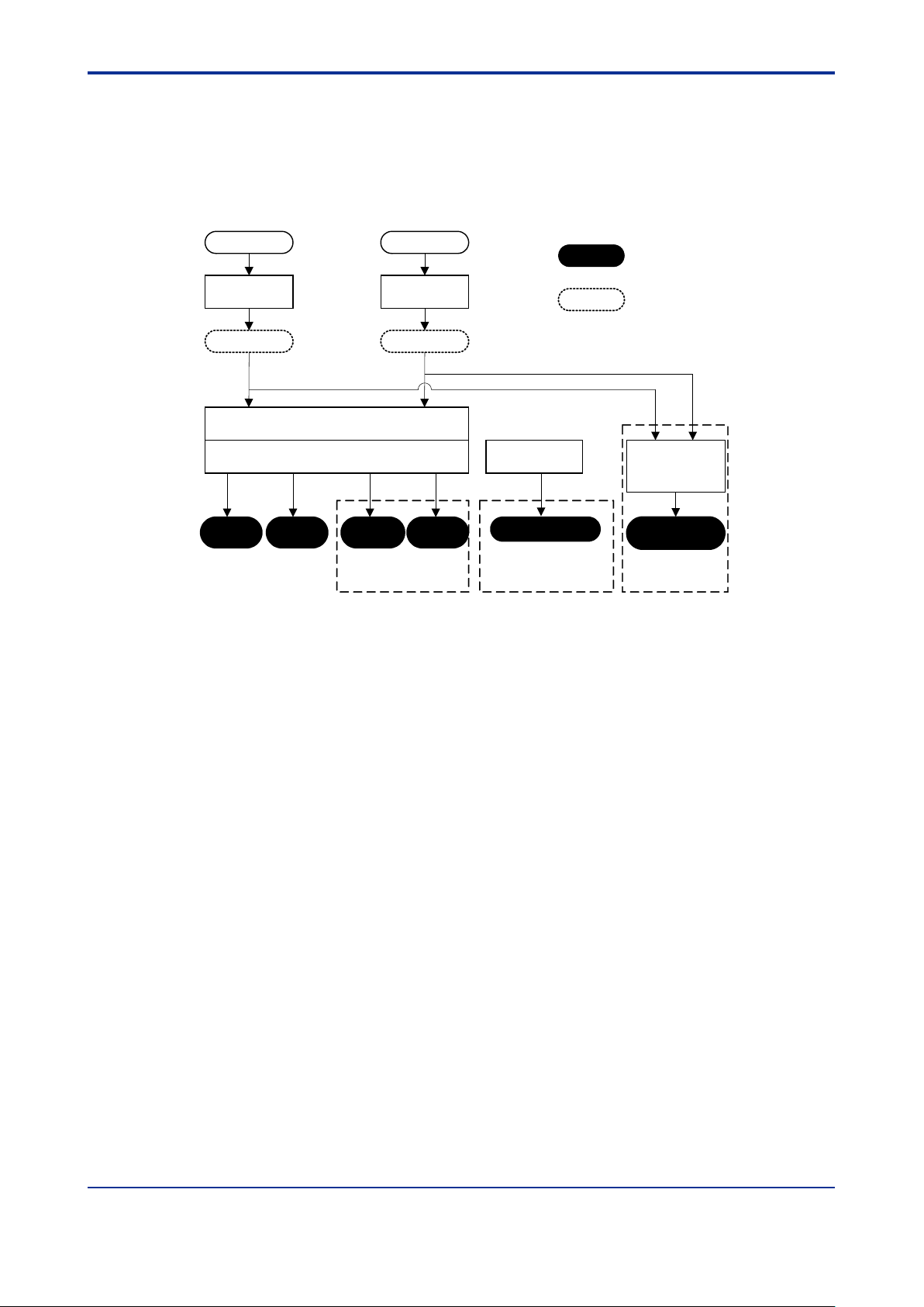
/RLY4
Input 1
Input 2
Input
processing
PV1
Input
processing
PV2
Alarm detection processing
Alarm connection/output processing
Alarm
output 1
Alarm
output 2
Alarm
output 3
Alarm
output 4
Retransmission
output
Retransmission
output
processing
Failure output
Terminal
symbol name
Parameter
displayed
/VLT,/CUR
When /RLY4,/VLT,or
/CUR is not specified
Self-
diagnosis
Internal Function Block Diagram
The following shows the internal function block diagram. For more information, see the
Description of Each Function section.
Figure 4.2 Internal Function Block Diagram
Page 19
<4. FUNCTIONS >
4-3
IM 01B04K03-02E
8th Edition: Jan.29,2021-00
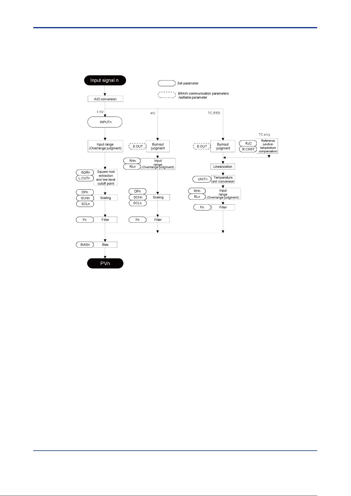
4.2 Input Processing Function
Two input points are provided. The following processing is done with respect to each
input (see Figure 4.3). Encircled symbols are parameter symbols appearing on the
display setter. "n" takes value 1 or 2.
Figure 4.3 Input Processing Function Block Diagram
Description of Each Function:
• A/D conversion: Performs A/D conversion of input signals.
• Burnout (B.OUT): If an input signal is mV, thermocouple, or RTD input, the action to
be taken in case of burnout can be set. (This can be specified according to an
option code. Settings can be changed via a PC (VJ77) or the JHT200 Handy
Terminal after delivery.)
• Temperature unit conversion (UNITn): Allows temperature units (°C, K or °F) to be
set if an input signal is thermocouple or RTD input.
Page 20
<4. FUNCTIONS >
4-4
IM 01B04K03-02E
8th Edition: Jan.29,2021-00
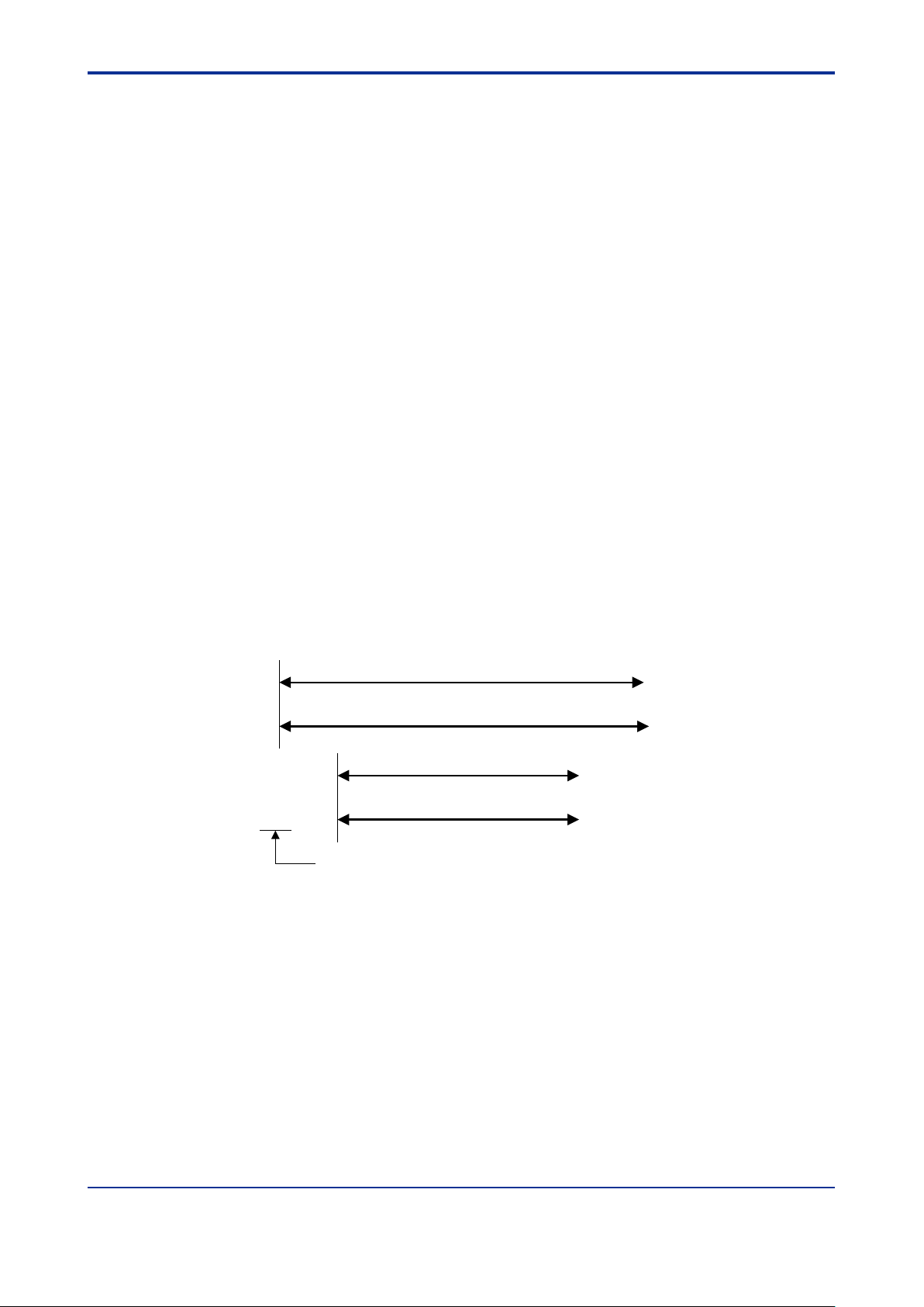
0.0 mV (RL1) 100.0 mV (RH1)
Default input range
0.0 (SCL1) 100.0 (SCH1)
Default scale
10.0 mV (RL1) 80.0 mV (RH1)
Measuring input range
1000 (SCL1) 20000 (SCH1)
Measuring scale
Decimal point position registered at DP1.
• Input range (RHn, RLn): An input range should be set if an input signal is mV or
temperature input. If an input value is -6.25% or less, or greater than 106.25% of the
input range, an input overrange occurs. For actions to be taken in the event of an
input overrange, see Section 8.2, "Actions under Fault Conditions."
• Square root extraction (SQRn, L.CUTn): If an input signal is 1 to 5 V DC, the
availability of square root extraction and a low-level cutoff point can be specified.
Specification of a low-level cutoff point is enabled only when square root extraction
is available. For inputs below the low-level cutoff point, no square root is extracted.
(Linear characteristics apply for any inputs below the low-level cutoff point.)
• Filter (Fn): This is a first-order lag filter. The time constant can be set in the range of
0.0 to 200.0 seconds. Note that for the actual time constant, a hardware filter time
constant of approx. 0.1 second will be added to the noted setting.
• Scaling (DPn, SCHn, SCLn): If an input signal is mV or 1 to 5 V DC, scaling can be
applied to a range specified by the input range (RHn, RLn). A value converted by
scaling (a value obtained by adding bias to this value if bias is used) becomes PVn.
The initial value of scaling is 0.0 to 100.0 (DPn=1, SCHn=100.0, SCLn=0.0).
<How to Set Input Range and Scaling>
The following is the example when input range of 10.0 to 80.0 mV is scaled to 1000 to
20000.
(1) Set the input range at the parameters RL1 and RH1.
(Example: RL1=10.0, RH1=80.0)
(2) Set the input decimal point position matched to the unit system actually in use at
DP1.
(Example: DP1=0)
(3) Set the scale range at the parameters SCH1 and SCL1.
(Example: SCL1=20000, SCH1=1000)
(Example)
Figure 4.4 Scaling
Note: Reverse scal ing (SCH1 < S CL1) is also possible.
The al arm unit will not operate normal ly when SCH1 is set to equal SCL1. Change the setting.
• Bias (BIASn):
A bias value can be added to scaling values.
This allows error to be compensated when there is an error between the input value
and the indicated value.
Bias can be set within the range ±10% [(SCH1 - SCL1) x 0.1] of the scaling width.
• PVn:
The value obtained by adding bias to the scaling value.
Page 21
<4. FUNCTIONS >
4-5
IM 01B04K03-02E
8th Edition: Jan.29,2021-00
Alarm
detection 3
Alarm
detection 2
Alarm
detection 1
HYS1
HI alarm
LO alarm
1H
1L
MOD1
Deviation
(PV1-PV2)
Rate-ofchange
PV1
Rate-of-
change
PV2
MOD3
HI alarm LO alarm
3H
3L
Set parameter
PV1
PV2
PV1
PV2
MOD2
HI alarm
LO alarm
2H 2L
PV1
PV2
DV
PV1.VL
PV2.VL
AND
ALn_H
ALn_L
OR
Connected to
AL1_H and
AL1_L
TMn
ACTn
Output timer
RL
NCCOMNO
AN.OR.n
ALMn
Lamp
TM1
ACT1
AND
AL1_H
AL1_L
OR
Connected to
AL1_H and
AL1_L
Output timer
RL
NCCOMNO
AN.OR.1
ALM1
Lamp
Parameter to be displayed
VL1.TM
HYS2
VL2.TM
HYS3
VL3.TM
TM.M
TM.M
ON.TM1
OFF.TM1
ON.TMn
OFF.TMn
Same connections as
MOD1
Same connections as
MOD1
Alarm output n (n=2 to 4. Note that n=3 or 4 is for /RLY4 only.)
Alarm output 1
Connected to 1H, 1L,
2H, 2L, 3H, and 3L
Alarm1
connection
result
Alarm n
connection
result
Alarm-detecting sectionsAlarm connection/output sections
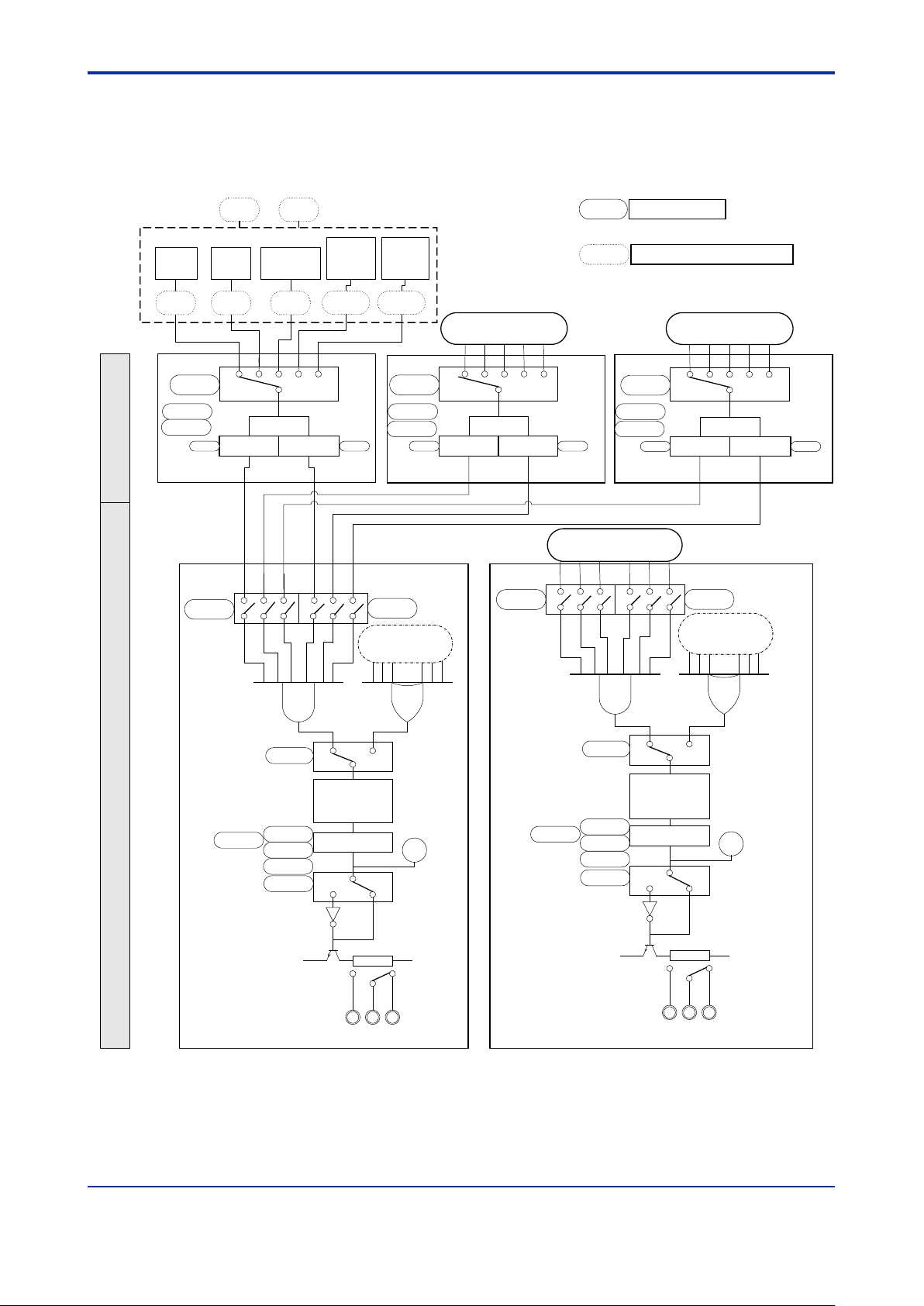
4.3 Alarm Processing Function
As shown in Figure 4.5, the SDAU's alarm function consists of the alarm-detecting
sections and alarm connection/output sections, each of which functions independent of
the others.
Figure 4.5 Alarm Processing Function Block Diagram
Page 22
<4. FUNCTIONS >
4-6
IM 01B04K03-02E
8th Edition: Jan.29,2021-00
Low-limit alarm
provided
nL
nH
HYSn
HYSn
Input
High-limit alarm
provided
4.3.1 Alarm-Detecting Sections
There are three alarm-detecting sections, which set each of the following items (see
Figure 4.5). Those in parentheses show parameter symbols to be displayed on the
display setter. "n" takes value 1, 2, or 3.
• Input mode (MODn): Selects a target input at alarm detection-n from among input-1
absolute alarm, input-2 absolute alarm, deviation alarm (input 1 - input 2), input-1
rate-of-change alarm, and input-2 rate-of-change alarm.
If the same PVn rate-of-change alarm is set to the multiple MOD, the rate-of-change
of MODn having smaller n value is displayed in PVn.VL parameter.
For example, MOD1=MOD2=MOD3=4: Input 2 rate-of-change (PV2.VL), and
VL1.TM=10, VL2.TM=5, VL3.TM=3, PV2.VL displays PV2 rate-of-change for 10
seconds.
• Hysteresis (HYSn): Sets hysteresis at alarm detection-n in engineering units (range:
0 to 32000). (This is not applicable to rate-of-change alarms.)
• Rate-of-change alarm sampling time (VLn.TM): Available when the input mode is
set to rate-of-change alarm. A rate-of-change is obtained as follows:
Example: When MOD1 = PV1 rate-of-change alarm and VL1.TM = 10 sec. are set,
Rate-of-change = current value (present PV1 value) - previous value (PV1
value 10 sec. before)
• High-limit alarm setpoint (nH): Sets the high-limit setpoint at alarm detection-n in
engineering units (range: -19999 to 32000). High-limit alarm cannot be used as lowlimit alarm.
• Low-limit alarm setpoint (nL): Sets the low-limit setpoint at alarm detection-n in
engineering units (range: -19999 to 32000). Low-limit alarm cannot be used as highlimit alarm.
• Alarm detection repeatability: Same as input conversion accuracy
Figure 4.6 Alarm Action When Hysteresis is Set
Page 23

<4. FUNCTIONS >
4-7
IM 01B04K03-02E
8th Edition: Jan.29,2021-00
[°C]
[Sec.]
Alarm action
when n.H = +30°C
Normal
Normal
100
80
60
40
20
0
V
Ln.TM
+40°C
+30°C
-20°C
-40°C
+30°C
Alarm action
when n.L = -20°C
Normal Normal
Alarm
Alarm
Alarm
Figure 4.7 Action to be Taken When Input is Rate-of-change Alarm
4.3.2 Alarm Connection/Output Sections
There are two alarm connection/output sections (four for the /RLY4 option), which set
each of the following items (see Figure 4.5).
Those in parentheses show parameter symbols to be displayed in the display setter. "n"
takes value 1 or 2 (up to 4 for the option /RLY4).
• Alarm output connection (ALn_H, ALn_L): ALn_H specifies whether to connect the
high-limit alarm detection results of MOD1 to MOD3. ALn_L specifies whether to
connect the low-limit alarm detection results of MOD1 to MOD3.
• Alarm AND/OR specification (AN.OR.n): Specifies if the results of alarm output
connections are AND-connected or OR-connected.
• Alarm timer mode (TM.M): Selects the alarm timer mode. This is common to alarm
outputs 1 and 2 (or alarm outputs 1 to 4 for the /RLY4 option).
0: Alarm output timer (timer causing alarm output to delay: equivalent to SDAU*E)
1: ON/OFF delay timer (alarm dead time)
Page 24
<4. FUNCTIONS >
4-8
IM 01B04K03-02E
8th Edition: Jan.29,2021-00
TMn setpoint (sec.)
Alarm output resolution (sec.)
0 to 39
0.15
40 to 79
0.3
80 to 159
0.6
160 to 319
1.2
320 to 600
2.4
• Alarm output timer (TMn): Sets the alarm output delay for alarm n. The alarm unit
outputs an alarm when the time period set in TMn has elapsed after the connection
of alarm n resulted in an alarm status. Time can be specified in the range of 0 to 600
seconds (in 1 sec. intervals). However, a time lag of approx. 0.2 second will be
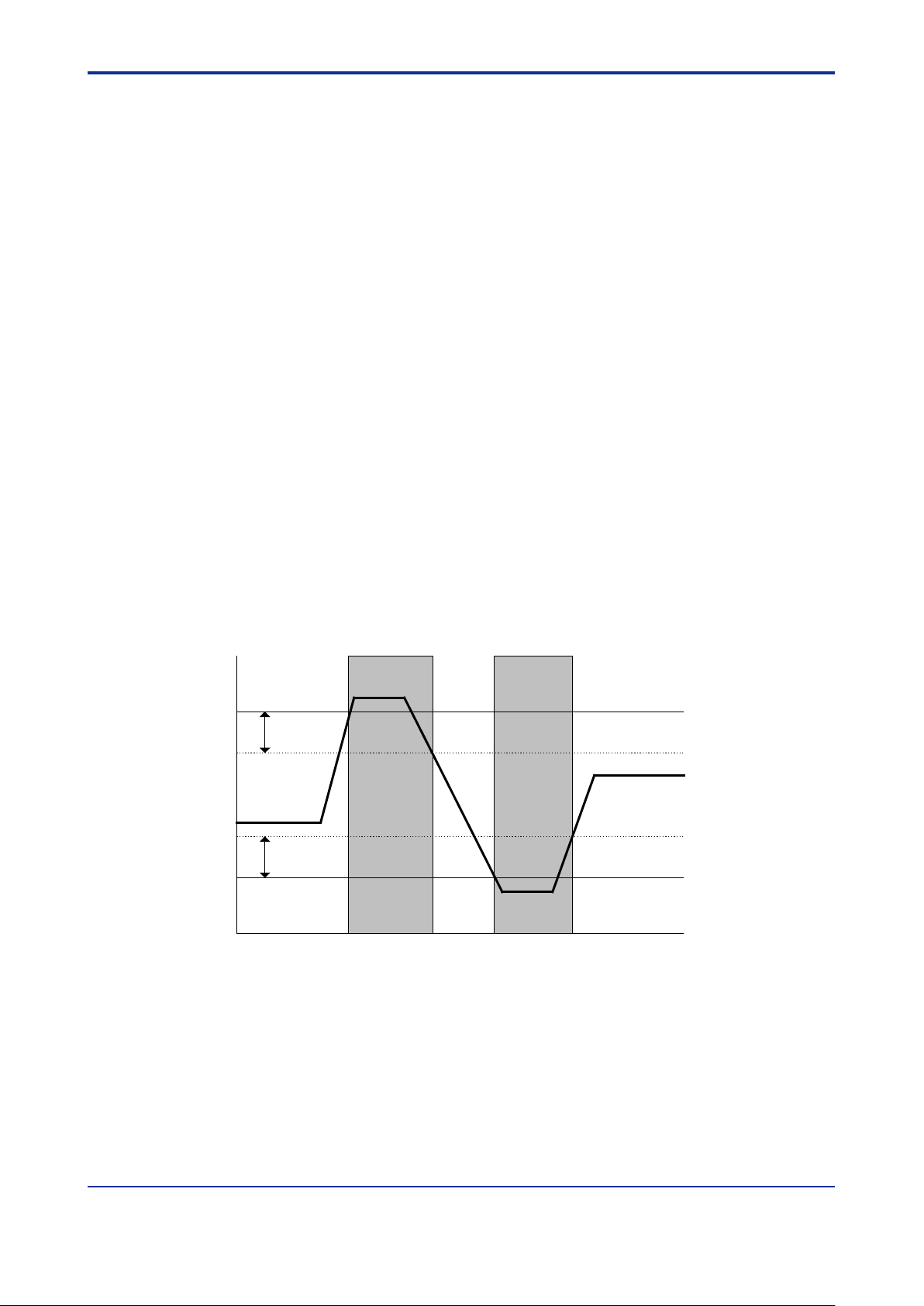
added to this setting as dead time to prevent erroneous alarm action.
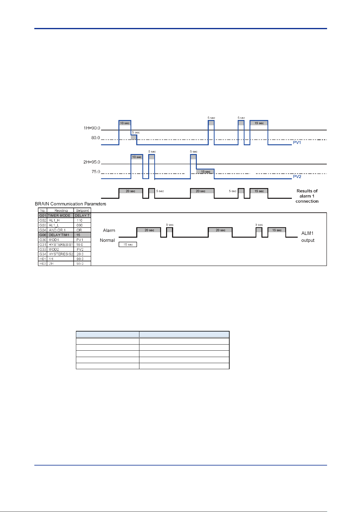
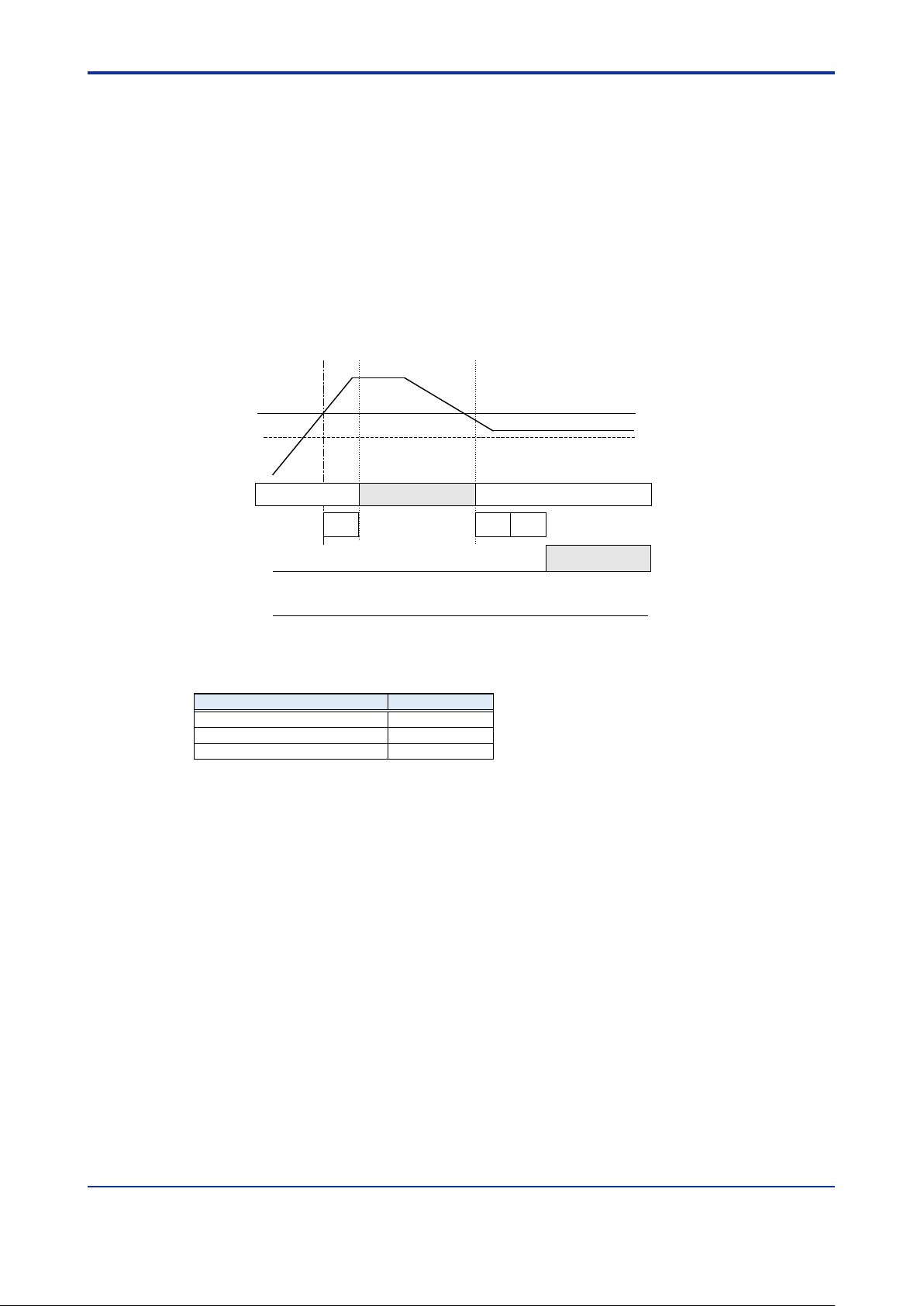
Figure 4.8 shows an example of the alarm actions taken by ALM1 when the alarm
output timer is set so that alarms to be output to ALM1 are delayed by 15 seconds if
an alarm is detected for either the 90.0 (hysteresis: 10.0) high limit alarm setpoint of
PV1 or the 95.0 (hysteresis: 20.0) high limit alarm setpoint of PV2.
Figure 4.8 Alarm Output Actions to be Taken When Alarm Output Timer is Set
Moreover, if a timer setpoint is changed, alarm status becomes identical with the
alarm status of that time, causing the timer function to work from that time on. The
alarm output resolution is as shown in the following table according to the setpoint
of the alarm output timer.
For example, if an alarm status occurs for one second with the alarm output timer set at
600 sec., an alarm is output for 2.4 seconds, between 597.6 to 602.4 seconds later.
ALM1 and ALM2 can be HOT started, while ALM3 and ALM4 are always COLD started.
(For HOT/COLD starts, see Section 4.6, "Function of Recovery from Power Failure.")
Page 25
<4. FUNCTIONS >
4-9
IM 01B04K03-02E
8th Edition: Jan.29,2021-00
• Alarm-n ON delay timer (ON.TMn): Sets dead time after which the alarm turns ON.
If an input value is within an alarm range for a time set by ON.TMn, an alarm status
occurs. If the input returns to the normal range before the time set by ON.TMn
elapses, no alarm turns ON.
• Alarm-n OFF delay timer (OF.TMn): Sets dead time after which the alarm turns OFF.
If an input value is within a normal range for a time set by OF.TMn, a normal status
is brought about. If the input returns to an alarm range before the time set by
OF.TMn elapses, the alarm does not turn OFF.
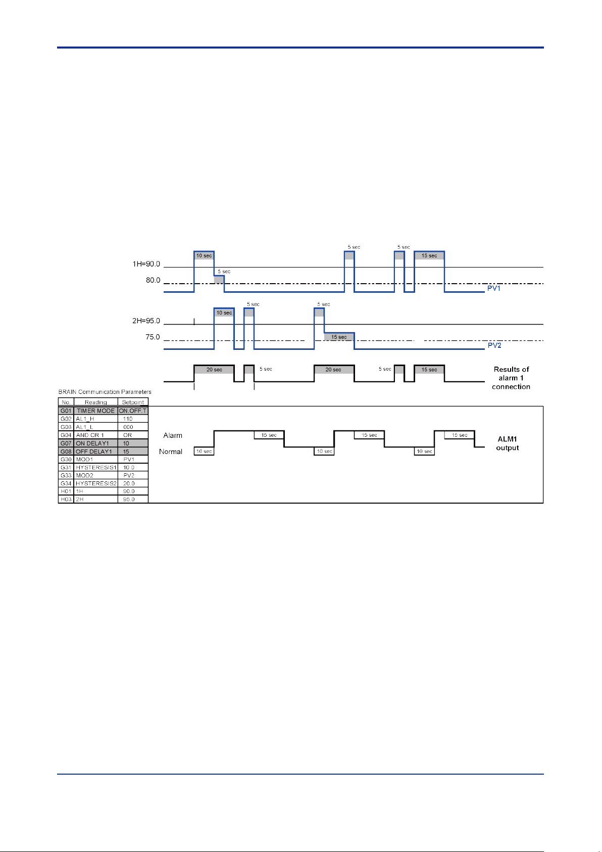
Figure 4.9 shows an example of the alarm actions taken by ALM1 when the alarm n
OFF delay timer is set so that the dead time of alarms to be output to ALM1 is 10
seconds and the dead time before these alarms are canceled is 15 seconds if an
alarm is detected for either the 90.0 (hysteresis: 10.0) high limit alarm setpoint of
PV1 or the 95.0 (hysteresis: 20.0) high limit alarm setpoint of PV2.
Figure 4.9 Alarm Actions to be Taken When Alarm-n ON/OFF Delay Timers are Set
• Direction of relay action (ACTn): Specifies energized/de-energized status of a relay
in a condition where no alarm has occurred.
Energized at normal operation (ACTn=1)
A relay is energized when the alarm n detection result is in a normal state.
De-energized at normal operation (ACTn=0)
A relay is energized when the alarm n detection result is in an alarm state.
• RLYn TEST: Relay action test (exclusive to a PC (VJ77) or the JHT200 Handy
Terminal)
This is the relay action test function. It allows a relay to turn ON/OFF regardless of
the current alarm detection results. (Note: Make sure that your process is not
affected by the relay action test before using this function.)
One set of transfer contacts are provided for each output section. An alarm state can be
checked with the ALM lamp on the front panel of the alarm unit (which lights up if an
alarm occurs) and by checking the ALMn parameter displayed on the display setter.
Page 26
<4. FUNCTIONS >
4-10
IM 01B04K03-02E
8th Edition: Jan.29,2021-00
PV1
PV1 - PV2
PV2
AN.OR.1
AND
OR
AL1_H
AL1_L
TM1
ACT1
ALM1
AN.OR.2
AND
OR
AL2_H
AL2_L
TM2
ACT2
ALM2
MOD1
HYS1
1H=80
1L
MOD2
HYS2
2H=50
2L=40
MOD3
HYS3
3H=70
3L
PV1 rate-of-change
PV2 rate-of-change
4.3.3 Example of Setting the Alarm Functions
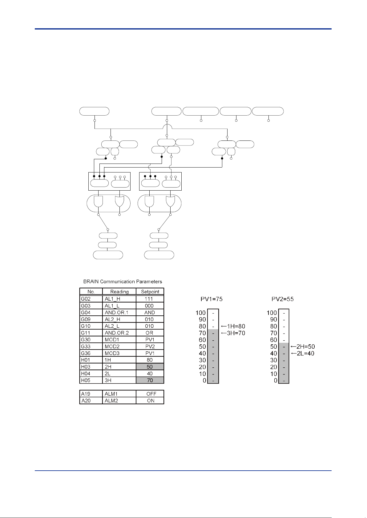
Example of Setting 1
Condition A)
ALM1: ALM1 alarm is output if all of the following are generated: the high high-limit
alarm of input 1 (1H = 80), the high-limit alarm of input 1 (3H = 70), and the
high-limit alarm of input 2 (2H = 50).
ALM2: ALM2 alarm is output if either the high-limit alarm (2H = 50) or low-limit alarm
(2L = 40) of input 2 is generated.
Figure 4.10 Alarm Connections for Condition A
Figure 4.11 Details of Parameter Settings
The parameter settings for condition A are as shown in the table above. When input 1
and input 2 are in the condition as shown in the figure above, the 2H and 3H parameters
enter the alarm state and only ALM2 outputs an alarm. (ALM1 outputs no alarm because
1H has not been in the alarm state.)
Page 27

<4. FUNCTIONS >
4-11
IM 01B04K03-02E
8th Edition: Jan.29,2021-00
mV input
Thermocouple input
RTD input
Span
10 to 100 mV DC
10 to 63 mV
elect romotive force)
50 to 500°C
Zero elevation
Three times the span
whichever is smaller
Three times the span or within ±25 mV,
Five t imes or less
4.4 Retransmission Output Function (for /VLT
and /CUR Options)
The SDAU digital alarm unit with the /VLT or /CUR option can output an input signal as
retransmission output in order to use it in a recorder, etc.
The retransmission output function is set using the following parameters.
For more information on each parameter, see Chapter 6, "PARAMETERS."
RET: Selects the retransmission output type (selectable from None, PV1, PV2, and
PV1 - PV2)
RTH: Maximum value of retransmission output scale
RTL: Minimum value of retransmission output scale
Retransmission Output Accuracy Guaranteed Range:
(RTH-RTL)
(RTL)
Note1: The retransmission output accuracy guaranteed range is within the noted accuracy range and within 0.0 to 100.0% of
the span (RTH - RTL ).
or within ±50 mV,
(converted based on thermo
whichever is smaller
the s pan
Page 28
<4. FUNCTIONS >
4-12
IM 01B04K03-02E
8th Edition: Jan.29,2021-00
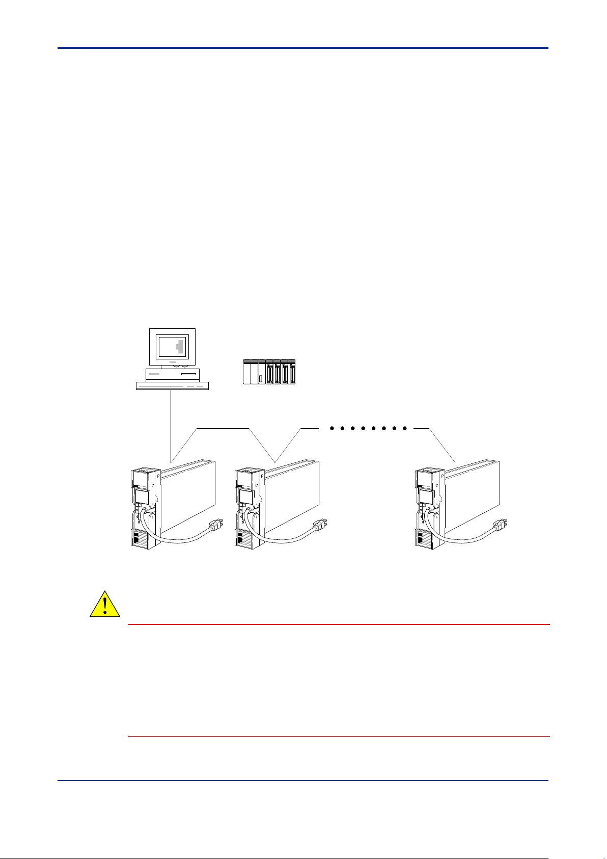
PC
A maximum of 1,200 m ; up to 31 slave stations connected.
Programmable logic
controller (FA-M3, etc.)
or
4.5 Communication Function (for /COM Option)
The SDAU alarm unit can communicate with a device with an RS-485 communication
interface, allowing input values to be read out and/or parameters to be read out or
written in.
For more information, see YS80*R Rack-Mounted Instruments Communication
Functions User’s Manual (IM 01B04F01-20E).
- Communication Interface : 1 channel
- Standards : EIA RS-485
- Communication System : 2-wire, half-duplex
- Baud Rate : 1200, 2400, 4800 and 9600 bps
- Communication Protocol : MODBUS, PC-Link, and Ladder
- Maximum Units Connectable : 31 units
- Maximum Communication Distance : 1200 m
- Communication Cable : Twist pair cable with shield (Wire size: AWG24 or
equivalent.)
Figure 4.12 Connection with a PC
CAUTION
• RS-485 communication is not available when a PC (VJ77) or the Handy Terminal is connected to
the BRAIN connector on the front panel.
When using a PC (VJ77) or the Handy Terminal, connect a PC (VJ77) or the Handy Terminal after
removing the RS-485 connector so that a PC (VJ77) or the Handy Terminal connector can be
easily disconnected.
• Writing via RS-485 communication is not possible if the Parameter Write Protect jumper (W.P.) is
set to ON or the Communication Write Protect Setting parameter (COMMU) is set to “1: Protect”.
Page 29
<4. FUNCTIONS >
4-13
IM 01B04K03-02E
8th Edition: Jan.29,2021-00
H=75.0
POWER OFF
POWER ON
HYS=10%
10
seconds
POWER ON
Normal
When HOT start is set:
When COLD start is set:
Normal
Normal
Alarm
10
seconds10seconds
Parameter Symbol
Setpoint
H (alarm setpoint nH)
75.0%
HYS (hysteresis)
10.0%
TM ( alarm output timer)
30 seconds
4.6 Function of Recovery from Power Failure
The SDAU alarm unit's recovery from power failure function operates as described
below, depending on the setting of the HOT start/COLD start parameter.
HOT start: Continues operation from the alarm status just before a power failure.
Note1: W hen t he alarm t im er m ode is set to alarm output tim er, ALM3 and ALM4 cann ot be HOT started.
Note2: HOT start s also cannot be m ade for rate-of-change alarm s. F or these alarm s, the S DAU judges if an alarm has
COLD start: Starts operation by assuming that power-on input has been continued
(provided that hysteresis has not been activated).
The following shows differences in alarm actions between HOT and COLD setpoints.
occurred at the instant when the change time of a rate-of-change alarm has elapsed, by regarding the value at
recovery from pow er failure as the previous value.
Figure 4.13 Alarm Action for HOT and COLD Starts
Parameter Setting Conditions for the Conditions in the Figure Above
Note: Even when the HOT start parameter is set, if a power failure occurs during any of
the following procedures, a HOT start is not possible.
• During input adjustment
• While a parameter is being changed (with a key switch, a PC (VJ77), JHT200
Handy Terminal, or through RS-485 communication)
• During initial setting at power ON
Page 30

<4. FUNCTIONS >
4-14
IM 01B04K03-02E
8th Edition: Jan.29,2021-00
1
ALM
2 E F
Lower half section of
the digital display
Fail (F) lamp
Error (E) lamp
4.7 Self-Diagnostic Function
The SDAU alarm unit has a self-diagnostic function capable of detecting a failure or
error in the unit itself.
If an error/failure is detected, notification is made by the following means: an error
indication appears on the lower half of the digital display, a parameter is displayed on
the upper half of it, a lamp on the front panel of the alarm unit is lit, the failure output
contact is de-energized (when /RLY4, /CUR, or /VLT is not specified), and/or an alarm
output contact is activated.
For details about the lamps on the front panel of an alarm unit with the /RLY4 option, see
Section 5.2, “Part Names of the Display Setter.”
The following describes actions to be taken in the event of error. (For more information,
see Section 8.2, "Actions under Fault Conditions.")
• Lighting of F lamp: CPU failure, A/D conversion failure, EEPROM failure, or RJC
error
(When the /RLY4 option is specified, this lamp is an indicator for ALM4.)
• Lighting of E lamp: Input signal overrange (Note)
(This lamp lights up if the input is more than 106.25% or less than -6.25% of the
input range high limit (RH1) or the input range low limit (RL1).)
Input burnout (Note)
HOT start is disabled (see Section 4.6, "Function of Recovery from Power Failure").
(When the /RLY4 option is specified, this lamp is an indicator for ALM3.)
Note: For input signal overrange or input burnout, the E lamp lights up and a failure output is sent out when the target input
signal is connected to an alarm output section.
• Failure output: (only when /CUR, /VLT, or /RLY4 option is not specified)
A failure contact output is provided if the F lamp comes on or the power supply fails.
Using the point-of-error failure output action parameter (front display parameter:
FAIL.M; BRAIN communication parameter: F40:FAIL MODE), define the action of
the failure contact to be taken when the E lamp comes on.
ON (0) = Provides a failure contact output when the E lamp comes on.
OFF (1) = Provides no failure contact output when the E lamp comes on.
(This parameter defaults to ON (0), as with SDAU*E.)
Page 31

<4. FUNCTIONS >
4-15
IM 01B04K03-02E
8th Edition: Jan.29,2021-00
Off
O
n
Alarm output
Failure output
Energization
(normal state)
De-energization
(alarm)
Energization
(normal state)
De-energization
(alarm)
Approx. 75 msec
At power-on
Approx. 40 msec
At power failure
0 (normal)
Unable to
communicate
Reading of the FAILST (D0022)
failure output by RS-485
communication
0 (normal)
Unable to communicate
Off
Off
F lamp
Power supply
24VDC
0V
Approx. 2 to 3 sec
Off
Off
E lamp
4.8 Alarm/Failure Outputs at Power-on and
Power Failure
The alarm and failure outputs function as explained below when the power is turned on
or if the power fails.
The following example explains a case where the action is defined as RLYn
ACTION=NRM ENERGIZED (normal-state energization) and no alarms or failures have
occurred.
When the power is turned on:
(1) The alarm output starts alarm action in approximately 2 to 3 seconds after power-on.
(2) The failure output is energized (normal state) in approximately 75 milliseconds after
the start of alarm action.
If the power fails:
(1) The failure output is de-energized (failure state) immediately after the power is cut
off.
(2) The alarm output is also de-energized in approximately 40 milliseconds after the
failure output is de-energized.
(3) The E lamp remains lit for approximately 40 milliseconds after the failure output is
de-energized.
Figure 4.14 Alarm/Failure Outputs at Power-on and Power Failure
Page 32

Blank Page
Page 33

<5. SETTING>
5-1
IM 01B04K03-02E
8th Edition: Jan.29,2021-00
5. SETTING
WARNING
When setting parameters, do not turn off the SDAU alarm unit.
Items to Confirm before Start of Operation
Before you start operation, inspect and confirm the following items:
(1) Draw out the internal unit from the rack case, and make sure that the specified fuses
are properly mounted in the fuse holders at the rear of the internal unit.
Make sure that the specified power supply fuse is properly mounted in the fuse
holder on the front for /TB option.
(2) W hen inserting the internal unit into the rack case, firmly connect the multi-pin
connectors for connecting the internal unit and the case.
(3) Make sure that power plugs are properly connected to the power outlet.
(4) Make sure that external wiring to the terminal block is properly connected.
(5) Make sure the parameter setpoint and change the setpoint if necessary. Set the
parameter following the steps (1) through (3) described below.
Setting procedure required for basic use
(1) Set the Input-Related Parameters.
For details on parameters, refer to Input-Related Parameters in Section 6.3, “Display
on Front Panel: List of Parameters” or parameter numbers F** SET (I/O) in Section
6.4, “BRAIN communication parameter: List of Parameters.”
For details on input processing function, refer to Section 4.2, “Input Processing
Function.”
(2) Set the Alarm-Related Parameters.
Note: Alarm setting parameters (1H, 1L, 2H, 2L, 3H and 3L) are not displayed because they are not c onnec ted for
fact ory-set default.
Set the alarm setpoint after completing the wiring for alarm.
For details on parameters, refer to Alarm Connection/Output Parameters and Alarm
Detection-Related Parameters in Section 6.3, “Display on Front Panel: List of
Parameters” or parameter numbers G** SET (ALM) and H** (ALM H/L) in Section
6.4, “BRAIN communication parameter: List of Parameters.”
For details on the alarm processing function, refer to Section 4.3, “Alarm Processing
Function.”
Before defining the alarm setting parameters, determine the method of alarm
connection by referring to Figure 4.5 “Alarm Processing Function Block Diagram” in
Section 4.3, “Alarm Processing Function.”
Page 34

<5. SETTING>
5-2
IM 01B04K03-02E
8th Edition: Jan.29,2021-00
(3) Set the Parameters for Optional Suffix Codes (for /VLT, /CUR or /COM only)
For details on parameters for “/ VLT” or “/CUR” option, refer to Retransmission
Output-Related Parameters in Section 6.3, “Display on Front Panel: List of
Parameters” or parameter numbers J** SET (RET) in Section 6.4, “BRAIN
communication parameter: List of Parameters.”
For details on retransmission output function, refer to Section 4.4, “Retransmission
Output Function.”
For details on parameters for “/COM” option, refer to Communication-Related
Parameters in Section 6.3, “Display on Front Panel: List of Parameters” or parameter
numbers K** SET (COM) in Section 6.4, “BRAIN communication parameter: List of
Parameters.”
For details on communication function, refer to Section 4.5, “Communication
Function.”
(4) Set the Point-of-error Failure Output Action Parameter (FAIL MODE).
(For options other than /RLY4, /VLT and /CUR)
For details on this parameter, see Section “Other Parameters” in 6.3, “Display on
Front Panel: List of Parameters” or see parameter number F40 in Section 6.4,
“BRAIN communication parameter: List of Parameters.”
For details on actions in case of failure, see Section 8.2, “Actions under Fault
Conditions.”
Page 35

<5. SETTING>
5-3
IM 01B04K03-02E
8th Edition: Jan.29,2021-00
5.1 Name of Components
The following shows the name of SDAU components.
Figure 5.1 Names of Components
Page 36

<5. SETTING>
5-4
IM 01B04K03-02E
8th Edition: Jan.29,2021-00
ALM
1 2 3
4
ALM
ALM3 and ALM4 lamps
(Alarm status indicator lamps)
<Digital display for /RLY4 option>
5.2 Part Names of the Display Setter
Figure 5.2 Part Names of the Display Setter
Note1: When using a PC (VJ77) or the Handy Terminal, connect a PC (VJ77) or the Handy Ter m i nal aft er rem oving the RS-
485 connector.
Note2: W hen the /RLY4 option is specified, the ALM3 and ALM4 lamps take the place of the E and F lamps.
Page 37

<5. SETTING>
5-5
IM 01B04K03-02E
8th Edition: Jan.29,2021-00
Display/indication
Function
Parameter display section
Displays a parameter symbol in an 11-segment indication.
Symbols in the following table.
Setpoint display s ect ion
Displays the status of a parameter displayed in the parameter display
setpoint .
ALM (Alarm-1 and -2 status
indicator) lamps (yellow)
Light up in the event of an alarm.
ALM (Alarm-3 and -4 status
indicator) lamps (yellow)
Provided only for the /RLY4 option. These lamps light up in the event
of an alarm.
E (Error) lamp (yellow)
Not provided for the /RLY4 option.
Conditions."
F (Fail) lamp (red)
Not provided for the /RLY4 option.
Conditions."
LED
Signal
LED
Signal
LED
Signal
A N 1
B O 2
C P 3 D Q 4
E R
indicator)
5
F S 6 G T 7 H U 8
I
V 9
J W 0 K X
L Y
M Z
Functions of the Digital Display Section
Table 5.1 Functions of the Digital Display Section
For the display of letters in 11 segments, see a List of LED Dis play
section (such as an input value, alarm status, self -diagnostic result) or
This lamp lights up in the event of an internal er ror such as input
burnout.
For more information, see Sec tion 8.2, "Actions under Fault
This lamp lights up in the event of failur e such as A/D conversion
failure.
For more information, see Sec tion 8.2, "Actions under Fault
List of LED Display Signal
Table 5.2 List of LED Display Signal
Alphabetic
character
Display
Alphabetic
character
(Upper side
digital
indicator)
r
(Lower side
digital
Display
Numeral
character
Display
Page 38

<5. SETTING>
5-6
IM 01B04K03-02E
8th Edition: Jan.29,2021-00
Name
Jumper Name
Optional Suffix
Parameter write-protect jumper
W . P. ―
Alarm output contact
ALM1
RY. 1
With /RLY4 specified
ALM2
RY. 2
With /RLY4 specified
ALM3
RY. 3
With /RLY4 specified
ALM4
RY. 4
With /RLY4 specified
Failure output contact action setting jumper
Without /RLY4, /VLT, or /CUR
5.3 Setting Jumpers
The SDAU alarm unit has the following jumpers.
Table 5.3 Setting Jumpers
action setting jumper
• Parameter write-protect jumper
W hen this jumper is set to ON, key switch-based parameter changes, parameter
changes via a PC (VJ77) or the JHT200 Handy Terminal, and RS-485
communication-based parameter changes will be disabled. In this case, pressing
the [→] key switch with a setting parameter displayed on the digital display causes
"LOCK" to appear in the upper half of the display setter. Press any key to return to
the status that was set before the "LOCK" indication.
• Failure output contact action setting jumper (jumper name: RY.4)
Set this jumper only when the /RLY4, /VLT, or /CUR option is not specified.
A failure output contact is always energized during normal operations.
This jumper is used to set the action to be taken in the event of failure (for more
information on CPU failure, and others, see Section 8.2, "Actions under Fault
Conditions.").
For NC setting: Closed if a relay is de-energized.
For NO setting: Open if a relay is de-energized.
• Alarm output contact action setting jumpers (jumper names: RY.1, RY.2, RY.3, RY.4)
Set these jumpers if the /RLY4 option is specified.
ALM1 is set with RY.1, ALM2 with RY.2, ALM3 with RY.3, and ALM4 with RY.4.
For NC setting: Closed if the relay is de-energized.
For NO setting: Open if the relay is de-energized.
Page 39

<5. SETTING>
5-7
IM 01B04K03-02E
8th Edition: Jan.29,2021-00
Jumper Name
BRAIN Communication
Parameter Name
Parameter write protect
A55: WRT PROTECT
Factory-shipped condition
RY.1 RY.2 RY.3 RY.4
NO
NC
NO NC NO NC NO NC
NO setting NO setting NO setting NO setting
RY.1 RY.2 RY.3 RY.4
NO NC NO NC NO NC NO NC
NC setting NC setting NC setting NC setting
Parameter write-protect
Setting jumper (factory-shipped condition)
When this jumper is set to ON,
parameter change is disabled.
Note: RY.1, RY.2 and RY.3 jumpers are provided only
when /RLY4 option is specified.
5.3.1 Checking Setting Jumpers and their Locations
The setting jumpers are located on the main board of the internal unit.
Pull out the internal unit and check the current settings.
Moreover, the current status of the parameter write-protect jumper can be checked via a
PC (VJ77) or the JHT200 Handy Terminal without pulling the internal unit out.
Figure 5.3 Jumper Settings
CAUTION
Operation is not guaranteed if the jumper is not set.
Page 40

<5. SETTING>
5-8
IM 01B04K03-02E
8th Edition: Jan.29,2021-00
5.3.2 Change of Setting Jumper
Follow the procedure below to change the setting jumpers:
(a) Pull the terminal block cover toward you to draw out the internal unit from the rack
case.
(b) Check the jumpers on the main board of the internal unit and change their settings
as desired. Use tweezers or another fine-tipped object to change the setting
jumpers.
(c) Return the internal unit to the rack case.
(d) Return the terminal block cover to its original position.
Page 41

<5. SETTING>
5-9
IM 01B04K03-02E
8th Edition: Jan.29,2021-00
Key
Functions
Display Mode
Setting Change Mode
Setting Fix Mode
Display Shutoff
Mode
Displays the next parameter.
Canc els a changed
parameter.
Canc els a changed
the next par ameter.
The SDAU enters this
→
Advances the SDAU to detailed
enable s tat e. ( Note 1)
Moves digit for setting.
Returns the SDAU
↑
Displays the previous parameter.
Changes a s etpoint.
No operation
SET
Canc els disabled HOT start
FLAG parameter is displayed.
Advances the SDAU to
Fixes a setpoint and
to display mode.
Enable
The SDAU enters a setting-and-change enable state.
If t he Par ameter W rite-Protect jumper has been set to ON, the ENBL s witch will be disabled.
Display
mode
(Moves the SDAU to
setting change mode)
(Moves digit for setting)
(Increments a setpoint)
(Displays the next parameter)
(Displays the previous parameter)
(Moves the SDAU
to setting fix mode)
Detailed alarm
status display
mode
(Enabled only when ALMn = 1
during display of ALMn)
(Cancels disabled HOT start impossible status flag if a FLAG parameter
is displayed)
(Displays error
description)
SET
SET
SET
Press any key switch to
return to display mode.
Display shutoff
mode
(The SDAU enters this mode if no
key switch is operated for more
than 30 min. while the display
mode parameter set to OFF.)
(Cancels a changed
setpoint, returns the SDAU
to display mode, and
displays the next
parameter.)
(Fixes a setpoint and moves the
SDAU to display mode)
Setting fix mode
(All-digits flashing)
(Cancels a changed
setpoint, returns the SDAU
to display mode, and
displays the next
parameter)
Setting change mode
(Single-digit flashing)
(Returns the SDAU to setting
change mode and moves
flashing to the next digit)
(Enabled only when FLAG ≠ 0000
during display of FLAG)
Error display
mode
(Displays an alarm setpoint
when an alarm has occurred)
5.4 Settings Done from the Front Panel of the
Alarm Unit
Using the display setter on the front panel of the alarm unit, you can display input values
and set parameters. For more information on the parameters, see Section 6.3, "Display
on Front Panel: List of Parameters."
5.4.1 How to Operate the Key Switches
Table 5.4 Key Switch Functions
Switch
value, ret urns t he
SDAU to display mode,
and displays the next
value, ret urns t he
SDAU to display
mode, and displays
mode if a key switch
is not oper ated for
more than 30 min.
while the display
mode paramet er is
alarm status dis play mode when
ALMn=1 is indicated.
Advances the SDAU to error
display mode if FLAG ≠ 0000 is
indicated.
Advances the SDAU to s etting
to setting change
mode and moves
flashing to the next
digit.
set to 0 = OFF.
When a key switch is
pressed in display
shutoff mode, the
SDAU ret urns to
display mode.
change mode when a settable or
changeable parameter is
displayed in setting and change
(ENBL)
impossible status flag when
If a password has been set, the SDAU enters a s etting-enable s tate only when a c orr ect password has
setting fix mode.
advances the SDAU
been entered after pr ess ing the ENBL switch.
Note 1: If the P arameter W ri te-Protect jumper on the main board has been set to ON, the SDA U does not advance t o the
setting change mode, but displays "LOCK" in the upper half of the digital display.
Figure 5.4 Key Switch Operations and Mode Transitions
Page 42

<5. SETTING>
5-10
IM 01B04K03-02E
8th Edition: Jan.29,2021-00
→
(2) Press the ENBL switch to bring about a setting and the change enable state.
(3) Alarm-1 high-limit alarm connection (AL1_H) appears.
Press the [ r] key several times.
SET
ALM
1 2 E F
SET
ALM
1 2
E F
(1) An input value (60.00) appears at power ON.
(4) Set alarm-1 high-limit alarm connection (AL1_H).
This causes the most significant digit of the display to flash.
Continuing to press the key causes the flashing indicator to move to
a digit on the right.
Press the [→] key
once.
Press the [] key.
This causes the value of a flashing digit to increment. Press this
key to bring about "1."
Press the [SET]
key.
This causes all the digits to flash. Press the [SET] key again to
cause "100" to light up. (This completes the setting.)
→
→
5.4.2 Settings Using Key Switches (Example)
The following describes how to set a parameter using the key switches. Put the SDAU
into a parameter setting-and-change enable state and follow the procedure below to set
the parameter.
CAUTION
If the Parameter Write-Protect jumper on the main board has been set to ON, the SDAU does not
advance to the setting change mode even if you press the [→] key switch in step (4) of the parameter
setting procedure. Thus, the flashing indicator cannot move to the next digit. In this case, "LOCK"
appears in the upper half of the digital display. To return to the display mode, press any key switch.
Parameter Setting Procedure
Figure 5.5 Parameter Setting Procedure
Page 43

<5. SETTING>
5-11
IM 01B04K03-02E
8th Edition: Jan.29,2021-00
How to set disable f unction
How to cancel disable
funct ion
Operations to be disabled
Parameter
Set the j umper (W. P.) on the
Set the j umper (W. P.) on
- Change of a parameter using key
485 communication
ENBL switch
If no key s witch is operated for
the change dis able s tate.
Press ENBL switch.
- Change of a parameter using key
Passwor d
parameter
Set a password using the SET
parameter.
Enter a correct passwor d
to the PASS parameter.
- Change of a parameter using key
switches
COMMU
parameter
Set the COMMU parameter to
"1."
Set the COMMU
parameter to "0."
- Change of a parameter through RS485 communication
Press ENBL switch Entry of a pass word: accepted
Setting and c hange disabl ed Setting and c hange enabled
When a pass word
has been set
W
hen no password
is set
Setting and c hange enabled
Last operation of a key switc h
Press ENBL switch
For 30 min.
Last operation of a key switc h
For 30 min.
Set ting and
change disabled
Set ting and
change disabled
Set ting and
change disabled
5.5 Parameter Change Disable Function
The SDAU alarm unit has four parameter-change-disable functions as shown in the
table below. They are used to prevent a parameter from being changed inadvertently.
Table 5.5 Parameter Change Disable Function
Write-Protect
jumper
main board to ON.
the main board to OFF.
switches
- Change of a parameter via a PC
(VJ77) or the Handy Terminal
- Change of a parameter through RS-
30 min. since the last operation
switches
of a key switch on the front
panel in the setting-and-change
enable s tat e, t he SDAU enters
Figure 5.6 Relationship between the ENBL Switch and Password Function
Page 44

<5. SETTING>
5-12
IM 01B04K03-02E
8th Edition: Jan.29,2021-00
ALM
Press any key switch.
Normal operation mode
ALM
Display shutoff mode
Only decimal points light up.
If no key switch is operated for
more than 30 minutes, the SDAU
moves to the display shutoff mode.
1 2
E F
1 2
E F
5.6 Various Display Modes
This section describes various display modes.
5.6.1 Display at Power ON
The model with display setter displays REV NO. (revision number of software for the
SDAU) for about 2 seconds after power ON.
Example of display (REV NO.2)
5.6.2 LOCK Display
If the upper half of the digital display shows "LOCK," the Parameter Write-Protect
jumper on the main board has been set to ON. Thus, no parameters can be set or
changed. The lower half of the digital display indicates nothing. Press any key switch to
return to the status that was set before "LOCK" was displayed.
5.6.3 Display in Display Shutoff Mode
If the upper and lower halves of the digital display show decimal points only, the SDAU
is in the display shutoff mode. This mode is activated if no key switch is operated for
more than 30 minutes with the display mode parameter (DSPM) set to 0 = OFF.
To return to the display mode, press any key switch in the display shutoff mode.
If an A/D conversion failure, EEPROM failure, EEPROM SUM failure or RJC error
occurs in the display shutoff mode, error indication has priority over the display shutoff
mode.
Moreover, during the occurrence of an A/D conversion failure, EEPROM failure,
EEPROM SUM failure or RJC error, the SDAU does not enter the display shutoff mode.
Figure 5.7 Display in Display Shutoff Mode
Page 45

<5. SETTING>
5-13
IM 01B04K03-02E
8th Edition: Jan.29,2021-00
ALM
1 2 E F
ALM
1 2
E F
5.6.4 Error Display
When the upper half of the digital display shows a PV parameter (PVn, DV, PVn.VL), the
lower half of the digital display indicates an error description. For more information, see
Section 8.2, "Actions under Fault Conditions."
Figure 5.8 Error Display
5.6.5 Display of Self-Diagnostic Results
If the result of self-diagnosis (FLAG) is any value other than "0000," pressing the [→]
key switch while the FLAG parameter is displayed causes the upper half of the digital
display to show an error description. Nothing appears on the lower half of the digital
display.
If multiple errors are present, press the [→] key switch to show the description of the
next error. For more information, see Section 8.2, "Actions under Fault Conditions."
Figure 5.9 Display of Self-diagnostic Results
Page 46

<5. SETTING>
5-14
IM 01B04K03-02E
8th Edition: Jan.29,2021-00
ALM
1 2 E F
5.6.6 Detailed Alarm Status Display
The detailed alarm status display shows the type of input for which alarm has occurred
and the relevant alarm setpoint.
To switch to the detailed alarm status display, press the [→] key switch while the alarm
status is "1." Each time the [→] key switch is pressed, the display switches to the next
alarm status by the number of alarm setpoints where an alarm has occurred.
The Detailed Alarm Status Display is not updated until the [→] key switch is pressed the
next time.
Note: In the detai led al arm status di splay, you cannot change an alarm setpoint. Information provi ded on the Detailed Alarm
The display condition is as shown in the figure below.
Stat us Di splay is not updated even if the on-display alarm is cancel ed when th e display is ac tive.
Nor is the i nformation up dated even if the on-display alarm setpoint is c hanged by paramet er set ting via BRAIN or
RS-485 communication.
Figure 5.10 Display Condition of Detailed Alarm Status Display
1. Upper three digits of the upper half of digital display: Shows the input connected to
an alarm point where an alarm has occurred. (PV1, PV2, DV, VL1, VL2)
2. Lower two digits of the upper half of digital display: Shows the alarm setpoint (1H,
1L, 2H, 2L, 3H, and 3L) where an alarm has occurred.
3. Lower half of digital display: Shows the setpoint of an alarm point where an alarm
has occurred.
The following shows an example of the detailed alarm status display.
Setting 1:
ALM1: ALM1 alarm is output if all of the following are generated: the high high-limit
alarm (1H) of input 1, the high-limit alarm (3H) of input 1, and the high-limit
alarm (2H) of input 2.
ALM2: ALM2 alarm is output if either the high-limit alarm (2H) or the low-limit alarm
(2L) of input 2 is generated.
Setting 2:
ALM1: ALM1 alarm is output if one of the following is generated: the high high-limit
alarm (1H) of input 1, the high-limit alarm (3H) of input 1, or the high-limit alarm
(2H) of input 2 is generated.
ALM2: ALM2 alarm is output if either the high-limit alarm (2H) or the low-limit alarm
(2L) of input 2 is generated.
Page 47

<5. SETTING>
5-15
IM 01B04K03-02E
8th Edition: Jan.29,2021-00
For setting 1:
For setting 2:
ALM
1 2
E F
ALM
1 2
E F
ALM
1 2
E F
ALM
1 2
E F
ALM
1 2 E F
ALM
1 2
E F
ALM
1 2 E F
ALM
1 2 E F
→
No change (right arrow key switch is disabled because ALM1 = 0)
→
→
→ →
→
→
→
Figure 5.11 Detailed Alarm Status Display
The detailed alarm status display and its display procedure are as shown below when
parameters in the table are set in an input condition as shown in the figure above.
Figure 5.12 Examples of Detailed Alarm Status Display
Page 48

<5. SETTING>
5-16
IM 01B04K03-02E
8th Edition: Jan.29,2021-00
5.7 Settings Using the JHT200 Handy Terminal
The SDAU alarm unit has BRAIN communication parameters used to specify a function
or to adjust inputs/outputs. To display or set/change a parameter, connect the JHT200
Handy Terminal (*1) to this unit.
*1: The BT200 BRA IN Terminal of Yokogawa El ectric Corporation can also be used.
CAUTION
For details of operation and adjusting procedures of JHT200 Handy Terminal, refer to the
instruction manual “JHT200 Handy Terminal” (IM 77J50H01-01EN).
Figure 5.13 Connecting the Handy Terminal
Page 49

<5. SETTING>
5-17
IM 01B04K03-02E
8th Edition: Jan.29,2021-00
5.8 Settings Using a PC (VJ77)
The SDAU alarm unit has BRAIN communication parameters used to specify a function
or to adjust inputs/outputs. To display or set/change a parameter, connect a PC (VJ77) to
this unit.
CAUTION
For details of operation and adjusting procedures of VJ77 Parameters Setting Tool, refer
to the instruction manual “Model VJ77 PC-based Parameters Setting Tool” (IM
77J01J77-01E).
Figure 5.14 Connecting a PC (VJ77)
Page 50

Blank Page
Page 51

<6. PARAMETERS >
6-1
IM 01B04K03-02E
8th Edition: Jan.29,2021-00
6. PARAMETERS
6.1 Configuration of Parameters
The SDAU's parameters include display-only parameters (those shown in the shaded
areas of the parameter chart) and parameters that can be set and changed.
A parameter can be set in two ways: one is to set it using the key switches and the other
is to set it via a PC (VJ77) or the JHT200 Handy Terminal.
(For SDAU with the /COM option, a parameter can also be set through RS-485
communication.)
There are differences between the parameter symbols that are displayed on the display
setter on the front panel of the unit and those that are displayed on a PC (VJ77) or the
Handy Terminal due to some bearing on the display units. Moreover, there are also
parameters that can be set only via a PC (VJ77) or the Handy Terminal. Parameters
marked with “-” in Symbol appearing on digital display in Section 6.4, "BRAIN
Communication Parameter: List of Parameters" are applicable to it.
Of parameters that can be set and changed, those required to be set at setup can be
displayed on the display setter on the front panel by setting the SKIP parameter to "0."
If the SKIP parameter is set to "1," the parameters that can be set and changed,
excepting alarm setpoints (1H, 2H, 3H, 1L, 2L, 3L), are not displayed on the display
setter. A PC (VJ77) or the JHT200 Handy Terminal can display any parameters
regardless of the setting of the SKIP parameter.
Page 52

<6. PARAMETERS >
6-2
IM 01B04K03-02E
8th Edition: Jan.29,2021-00
PV1
PV2
DV
PV1.VL
PV2.VL
ALM1
ALM2
Setting of MODn determines the parameters to be displayed (PV1
and PV2 are always displayed)
Parameter DV is displayed also when parameter RET=3 (PV1-PV2)
/RLY4
provided?
ALM3
ALM4
In the event of an alarm (ALMn = 1), use key switches
to display an alarm setpoint where the alarm has
occurred.
Password
already set?
FLAG
No
Yes
In the event of an error (FLAG ≠ 0000), use key switches to
display an error description.
PASS
SKIP
No
Yes
SKIP=1
1H
1L
2H
2L
3H
3L
(To "F1" on the next page)
(From "SET" on the next page)
No
Yes
6.2 Display on Front Panel: Development View of
Parameters
SDAU-1xx Type Parameters
Figure 6.1 Chart of Parameters to be Displayed on SDAU-1xx Type Front-Panel Digital Display
Note: "nH" is displayed when an alarm is connected with ALn_H, while "nL" is di splayed when it is connected with ALn_L.
Page 53

<6. PARAMETERS >
6-3
IM 01B04K03-02E
8th Edition: Jan.29,2021-00
F1
Type of input-1
signal
1 to 5V
Yes
SQR1
RH1
RL1
UNIT1
TC or RTD
mV
SQR1=1
L.CUT1
RH1
RL1
TC
No
DP1
SCH1
SCL1
DP1
SCH1
SCL1
RJC
RJC=OFF
R.CNST
PV1
BIAS1
F2
SQR2
SQR2=1
Yes
L.CUT2
No
DP2
SCH2
SCL2
PV2
BIAS2
TM.M
AL1_H
AL1_L
AN.OR.1
ACT1
TM.M = ON/
OFF timer?
ON.TM1 TM1
OF.TM1
/RLY4
provided?
Yes
No
Yes
No
Yes
No
Yes
No
AL3_H
AL3_L
AN.OR.3
ACT3
TM.M = ON/
OFF timer?
TM3
Yes
No
ON.TM3
OF.TM3
AL4_H
AL4_L
AN.OR.4
ACT4
TM.M = ON/
OFF timer?
TM4
Yes
No
ON.TM4
OF.TM4
MOD1
1H
1L
MOD 1 = rate-of-
change alarm?
HYS1
Yes
No
VL1.TM
MOD2
2H
2L
MOD 2 = rate-of-
change alarm?
HYS2
Yes
No
VL2.TM
MOD3
3H
3L
Mode 3 = rate-of-
change alarm?
HYS3
Yes
No
VL3.TM
/COM
provided?
PSL
BPS
PRI
STP
DLN
ADR
COMMU
/VLT or /CUR
provided?
Yes
No
RET
RET≠0
Yes
No
RTH
RTL
Input 1 signal:
1-5 V?
Yes
No
CAL1.Z
CAL1.S
CAL2.Z
CAL2.S
H/C
DSPM
WNGR1
(From the previous page)
AL2_H
AL2_L
AN.OR.2
ACT2
TM.M = ON/
OFF timer?
Yes
No
ON.TM2 TM2
OF.TM2
Parameter to be displayed only
Additional parameter from SDAU*E
Parameter changed from SDAU*E
Input-Related Parameters
Alarm Connection/
Output Parameters
Alarm Detection-Related
Parameters
/RLY4, /VLT,
and /CUR
provided?
No
FAIL.M
Yes
SET
Page 54

<6. PARAMETERS >
6-4
IM 01B04K03-02E
8th Edition: Jan.29,2021-00
PV1
PV2
DV
PV1.VL
PV2.VL
ALM1
ALM2
Setting of MODn determines the parameters to be displayed (PV1 and
PV2 are always displayed)
Parameter DV is displayed also when parameter RET=3 (PV1-PV2)
/RLY4
provided?
ALM3
ALM4
In the event of an alarm (ALMn = 1), use key
switches to display an alarm setpoint where the
alarm has occurred.
Password
already
set?
FLAG
No
Yes
In the event of an error (FLAG ≠ 0000), use key switches to
display an error descript
PASS
SKIP
No
Yes
SKIP=1
1H
1L
2H
2L
3H
3L
(To "F1" on the next page)
(From "SET" on the next page)
No
Yes
SDAU-270 Type Parameters
Figure 6.2 Chart of Parameters to be Displayed on SDAU-270 Type Front-Panel Digital
Displays
Note: "nH" is displayed when an alarm is connected with ALn_H, while "nL" is di splayed when it is connected with ALn_L.
Page 55

<6. PARAMETERS >
6-5
IM 01B04K03-02E
8th Edition: Jan.29,2021-00
FAIL.M
F1
SNSR1?
mV
SNSR1
RTD
RJC=OFF
PV1
RJC
Yes
No
TM.M
AL1_H
AL1_L
AN.OR.1
ACT1
TM.M = ON/
OFF timer?
ON.TM1 TM1
OF.TM1
/RLY4
provided?
Yes
No
Yes
No
Yes
No
AL3_H
AL3_L
AN.OR.3
ACT3
TM.M = ON/
OFF timer?
TM3
Yes
No
ON.TM3
OF.TM3
AL4_H
AL4_L
AN.OR.4
ACT4
TM.M = ON/
OFF timer?
TM4
Yes
No
ON.TM4
OF.TM4
MOD1
1H
1L
Mode1 = Rate-of-
change alarm?
HYS1
Yes
No
VL1.TM
MOD2
2H
2L
MOD2 = Rate-of-
change alarm?
HYS2
Yes
No
VL2.TM
MOD3
3H
3L
MOD3 = Rate-of-
change alarm?
HYS3
Yes
No
VL3.TM
/COM
provided?
PSL
BPS
PRI
STP
DLN
ADR
COMMU
/VLT or /CUR
provided?
Yes
No
RET
RET≠0
Yes
No
RTH
RTL
H/C
DSPM
(From the previous page)
AL2_H
AL2_L
AN.OR.2
ACT2
TM.M = ON/
OFF timer?
Yes
No
ON.TM2 TM2
OF.TM2
Parameter to be displayed only
Additional parameter from SDAU*E
Parameter changed from SDAU*E
RH1
RL1
DP1
SCH1
SCL1
TC.TP1
UNIT1
RH1
RL1
RT.TP1
UNIT1
RH1
RL1
TC
BIAS1
mV RTD
TC
SNSR2?
RH2
RL2
DP2
SCH2
SCL2
TC.TP2
UNIT2
RH2
RL2
RT.TP2
UNIT2
RH2
RL2
PV2
BIAS2
SNSR1 or
SNSR2 =TC
R.CNST
WNGR1
WNGR2
SNSR2
F2
Input-Related Parameters
Alarm Connection/Output
Parameters
Alarm Detection-Related
Parameters
/RLY4, /VLT
or /CUR
provided?
No
SET
Yes
Page 56

<6. PARAMETERS >
6-6
IM 01B04K03-02E
8th Edition: Jan.29,2021-00
Symbol appearing on
digital display
Item
Name)
Description
Display
Initial
SDAU*E
SDAU*R
P1
PV1
PV1
Converts input 1 obtained after input
display.
-19999 to
P2
PV2
PV2
Converts input 2 obtained after input
display.
-19999 to
-
DV
DV ( deviation)
Displays a value of PV1 - PV2
-19999 to
32000
-
PV1.VL
PV1.VL (PV1 rateof-change)
Displays a PV1 rat e-of-change
-19999 to
32000
-
PV2.VL
PV2.VL (PV2 rateof-change)
Displays a PV2 rat e-of-change
-19999 to
32000
→
ALM1
Alarm-1 status
Displayed if alarm 1 has occurred.
display detailed alarm st atus.
0, 1
→
right)
ALM2
Alarm-2 status
Displayed if alarm 2 has occurred.
status.)
0, 1 - ALM3
Alarm-3 status
Displayed if alarm 3 has occur red.
status.)
0, 1 - ALM4
Alarm-4 status
Displayed if alarm 4 has occurred.
status.)
0, 1
→
FLAG
Self-diagnostic
Displays a value obtained by adding a value of
display the err or description.
00 to FFFF
6.3 Display on Front Panel: List of Parameters
There are parameters that are not displayed depending on the model, optional
suffix code, or parameter's setpoint. For more information, see Section 6.2,
"Display on Front Panel: Development View of Parameters."
When selecting a parameter for a choice using RS-485 communication, set a value
given in the Description column in the table below.
Parameters to be Displayed Only
(Parameter
processing, using SCH1 and SCL1 scales, to
processing, using SCH2 and SCL2 scales, to
(Same as
right)
(Same as
(Same as
right)
result
0: No alarm occ urred
1: Alarm oc curred
In the event of an alarm, us e key switches to
(Details are t he same as those of alar m-1
(Details are t he same as those of alar m-1
(Details are t he same as those of alar m-1
self -diagnostic result (hex.).
0000: Normal
0001: Input-1 overrange
0002: Input-2 overrange
0004: A/D converter failure
0040: HOT start error
0080: EEPROM SUM failure
0100: EEPROM failure
0800: Input-1 burnout
1000: Input-2 burnout
8000: RJC error
In the event of an error, us e key switches to
Range
32000
32000
Value
Page 57

<6. PARAMETERS >
6-7
IM 01B04K03-02E
8th Edition: Jan.29,2021-00
Symbol appearing on
digital display
Name
Description
Setting
Initial
SDAU*E
SDAU*R
→
F1
Input-1 filter
Sets first-order lag filter with respect to input
added to this setting.
0.0 to 200.0
0.0 sec.
-
SNSR1
Sensor type 1
0: TC
0 to 2
0
ordering)
→
SQR1
Input-1 square
Sets the availability of s quare root extr act ion
1: Provided
0, 1
0
-
L.CUT1
Low-level cutoff
Sets a low-level cutoff point t o be applied
available.
0.0 to 100.0%
1.0%
-
TC TP1
Thermocouple
1: Type K
changes.
1 to 10
1
-
RT.T P 1
RTD type 1
1: Pt100-90 (ITS-90, JIS’97)
changes.
1 to 4
1
-
UNIT1
Unit 1
0: °C 2: °F
1: K
0, 1, 2
0
-
RH1
High limit of
When input 1 is mV or temperature input,
(See the
(See the
Input-Related Parameters
(Same as
right)
(Same as
right)
(Parameter
Name)
root extraction
point 1
type 1
1.
Approx. 0.1 sec. specific to har dwar e is
1: mV
2: RTD
of input 1.
0: Not provided
when square root extraction of input 1 is
2: Type E
3: Type J
4: Type T
5: Type R
6: Type S
7: Type B
8: Type N
9: Type W3
10: Type W5
Note: This parameter is init ialized if SNSR1
sec.
Range
Value
(It em to be
specified
when
(It em to be
specified
when
ordering)
input-1 range
2: Pt100-68 (ITS-68, JIS’89)
3: JPt100 (JIS’89)
4: Pt50 (JIS’81)
Note: This parameter is init ialized if SNSR1
this par ameter sets the high limit of the
input-1 range.
Setting range:
mV input: -50.0 to 150.0
Temperature input: Measuring range,
provided that RL1 < RH1
Initial value:
(Except for the univer sal input type, this
item is t o be specified at purchase. )
mV input: 100.0
Temper ature input: Max. value of
measuring range
Position of dec imal point (Unit 1=°C or K):
Type W 3 or W 5: 0
Types other than W3 or W5: 1
Position of dec imal point (Unit 1=°F):
Type B, R, S, W3 or W 5: 0
Types other than the above: 1
Note: This parameter is init ialized if SNSR1,
TC.TP1, RT.TP1, or UNIT1 changes.
Description
column.)
(It em to be
specified
when
ordering)
Description
column.)
Page 58

<6. PARAMETERS >
6-8
IM 01B04K03-02E
8th Edition: Jan.29,2021-00
Symbol appearing on
digital display
Name
Name)
Description
Setting
Initial
SDAU*E
SDAU*R
-
RL1
Low limit of
When input 1 is mV or temperature input, this
TC.TP1, RT.TP1, or UNIT1 changes.
(See the
(See the
→
DP1
Decimal point
Sets the decimal point posit ions of SCH1 and
TC.TP1, RT.TP1, or UNIT1 changes.
0 to 3
1
H1
SCH1
Input-1 scale H
Sets the convers ion reference value when input
TC.TP1, RT.TP1, or UNIT1 changes.
-9999 to
100.0
L1
SCL1
Input-1 scale L
Sets the convers ion reference value when input
TC.TP1, RT.TP1, or UNIT1 changes.
-9999 to
0.0 - RJC
Availability of
If input 1 or input 2 is thermocouple input, this
1: Not available
0, 1
0
-
R.CNST
Fixed value of
When RJC is OFF, the setpoint of this
UNIT2).
-20.0 to
0.0°C
P1
PV1
PV1
Converts input 1 by SCH1 and SCL1 scales to
display.
-
-
-
BIAS1
Input-1 bias
Adds bias value to a value obtained aft er input
RL1 changes when IN1 is temperature input.
(See the
0
(Same as
right)
(Parameter
input-1 range
position of input
1
parameter sets the low limit of t he input-1
range.
Setting range:
mV input: -50.0 to 150.0
Temperature input: Measuring range,
provided that RL1 < RH1
Initial value:
(Except for the universal input type, this item
is t o be specified at purchase. )
mV input: 0.0
Temperature input: Min. value of measuring
range
Position of dec imal point (Unit1=°C or K):
Type W 3 or W 5: 0
Types other than W3 or W5: 1
Position of dec imal point (Unit1=°F):
Type B, R, S, W3 or W 5: 0
Types other than the above: 1
Note: This parameter is init ialized if SNSR1,
SCL1.
0: xxxx. ( wit h no decimal plac e)
1: xxx.x ( wit h one decimal plac e)
2: xx.xx ( wit h two decimal places )
3: x.xxx ( wit h three decimal plac es)
Note: This parameter is init ialized if SNSR1,
Range
Description
column.)
Value
Description
column.)
input reference
junction
compensation
RJC
1 = span point (5 V for 1-5 V input or RH1 for
mV input).
Note: This parameter is init ialized if SNSR1,
1 = zero point (1 V for 1-5 V input or RL1 for
mV input).
Note: This parameter is init ialized if SNSR1,
parameter sets the availability of referenc e
junction compensation.
0: Available
parameter becomes valid. Referenc e junction
temperature can be fixed to a certain value.
Note: This parameter is initialized if SNSR1 or
UNIT1 changes (refer ence temperature unit
is UNIT1).
If IN1 is any input other than TC and IN2 is
TC, it is initialized if SNSR2 or UNIT2
changes (reference temper ature unit is
processing and displays it as PV1.
Setting range: -19999 to 32000
W here, engineering unit span (EUS) =±10%
Position of decimal point: DP1
Note: This parameter is initialized if SNSR1,
TC.TP1, RT.TP1, or UNIT1, SCH1, or SCL1
changes. Moreover, it is initialized if an RH1 or
9999
9999
80.0°C
254.0 to
353.0K
-4.0 to
176.0°F
Description
column.)
273.1K
32.0°F
Page 59

<6. PARAMETERS >
6-9
IM 01B04K03-02E
8th Edition: Jan.29,2021-00
Symbol appearing on
digital display
Name
Name)
Description
Setting
Initial
SDAU*E
SDAU*R
→
F2
Input-2 filter
Sets first-order lag filter with respect to input
filter.)
0.0 to 200.0
0.0
-
SNSR2
Sensor type 2
0: TC
0 to 2
0
ordering)
→
SQR2
Input-2 square
Sets the availability of s quare root extr act ion
square root extraction.
0, 1
0
-
L.CUT2
Low-level cutoff
Sets a low-level cutoff point t o be applied
available.
0.0 to 100.0%
1.0%
-
TC.TP2
Thermocouple
(Details are t he same as those of
1 to 10
1
ordering)
-
RT.T P 2
RTD type 2
(Details are t he same as those of RTD type
1 to 4
1
ordering)
-
UNIT2
Unit 2
0: °C 2: °F
1: K
0, 1, 2
0
-
RH2
High limit of
When input 2 is mV or temperature input,
TC.TP2, RT.TP2, or UNIT2 changes.
(See the
(See the
-
RL2
Low limit of
When input 2 is mV or temperature input,
TC.TP2, RT.TP2, or UNIT2 changes.
(See the
(See the
→
DP2
Decimal point
Sets the decimal point posit ions of SCH2
decimal point position of input 1.
0 to 3
1
H2
SCH2
Input-2 scale H
Sets the convers ion reference value when
TC.TP2, RT.TP2, or UNIT2 changes.
-9999 to 9999
100.0
L2
SCL2
Input-2 scale L
Sets the convers ion reference value when
TC.TP2, RT.TP2, or UNIT2 changes.
-9999 to 9999
0.0
P2
PV2
PV2
Converts input 2 by SCH2 and SCL2 scales
to display.
-
-
(Same as
right)
(Same as
right)
(Parameter
root extraction
point 2
type 2
2.
(Details are t he same as those of input-1
1: mV
2: RTD
of input 2.
(Details are t he same as those of input-1
when square root extraction of input 2 is
ther moc ouple type 1.
Note: This parameter is init ialized if SNSR2
changes.
1.
Note: This parameter is initialized if SNSR2
changes.
sec.
Range
Value
(It em to be
specified
when
(It em to be
specified
when
(It em to be
specified
when
(Same as
right)
input-2 range
input-2 range
position of input
2
this par ameter sets the high limit of the
input-2 range.
(Details are t he same as those of the high
limit of input-1 range.
Note: This parameter is init ialized if SNSR2,
this par ameter sets the low limit of the input2 range.
(Details are t he same as those of the low
limit of input-1 range.
Note: This parameter is init ialized if SNSR2,
and SCL2.
Note: This parameter is init ialized if SNSR2,
TC.TP2, RT.TP2, or UNIT2 changes.
(Details are t he same as those of the
input 2 = span point (5 V for 1-5 V input or
RH2 for mV input).
Note: This parameter is init ialized if SNSR2,
input 2 = zero point (1 V for 1-5 V input or
RL2 for mV input).
Note: This parameter is init ialized if SNSR2,
Description
column.)
Description
column.)
Description
column.)
Description
column.)
Page 60

<6. PARAMETERS >
6-10
IM 01B04K03-02E
8th Edition: Jan.29,2021-00
Symbol appearing on
digital display
Name
Name)
Description
Setting
Initial
SDAU*E
SDAU*R
-
BIAS2
Input-2 bias
Adds bias value to a value obt ained after
temperature input.
(See the
0
(Parameter
input processing and displays it as PV2.
Setting range: -19999 to 32000
Where, engineering unit span (EUS) =
±10%
Position of dec imal point : DP2
Note: This parameter is init ialized if SNSR2,
TC.TP2, RT.TP2, or UNIT2, SCH2, or
SCL2 changes. Moreover, it is initialized if
an RH2 or RL2 changes when IN2 is
Range
Description
column.)
Value
Page 61

<6. PARAMETERS >
6-11
IM 01B04K03-02E
8th Edition: Jan.29,2021-00
Symbol appearing on
digital display
Name
Description
Setting
Initial
SDAU*E
SDAU*R
-
TM.M
Alarm timer
Sets alarm timer mode.
1: ON/OFF delay timer (alar m dead time)
0, 1
0
A
AL1_H
High-limit alarm
Sets connection of a high limit alarm t o be
ALM1, it is 101.
000 to 111
000 A AL1_L
Low-limit alarm
Sets connection of a low limit alarm to be
ALM1, it is 110.
000 to 111
000
AN/OR1
AN.OR.1
Alarm-1
Sets whether AL1_H- and AL1_L-based
1: AND connected
0, 1
0
→
right)
ACT1
Direction of
action
Sets the direction of an alarm-1 relay action.
1: Energized during normal operations
0, 1
0
→
right)
TM1
Alarm-1 output
Sets the output delay time of alarm 1.
0 to 600 sec.
0 sec.
-
ON.TM1
Alarm-1 ON
Sets dead time between the instant alarm-1
output.
0 to 999 sec.
0 sec.
-
O F. T M 1
Alarm-1 OFF
Sets dead time between the instant alarm-1
is stopped.
0 to 999 sec.
0 sec.
B
AL2_H
High-limit alarm
Sets connection of a high limit alarm to be
limit alarm connection of alarm 1. )
000 to 111
000
Alarm Connection/Output Parameters
(Parameter
Name)
mode
connection of
alarm 1
connection of
alarm 1
0: Alar m output timer (which delays alarm
output, equivalent to SDAU*E.)
output as alarm 1.
ABC
A: For 1H, 0: not connected, 1: connected
B: For 2H, 0: not connected, 1: connected
C: For 3H, 0: not connected, 1: connected
Note: For settings through RS-485
communication
0: 000
1: 001
2: 010
3: 011
4: 100
5: 101
6: 110
7: 111
E.g.: when 1H and 3H are connected to
output as alarm 1.
ABC
A: For 1L, 0: not connected, 1: connected
B: For 2L, 0: not connected, 1: connected
C: For 3L, 0: not connected, 1: connected
Note: For settings through RS-485
communication
0: 000
1: 001
2: 010
3: 011
4: 100
5: 101
6: 110
7: 111
E.g.: when 1L and 2L are connected t o
Range
Value
(Same as
(Same as
AND/OR
specificat ion
alarm-1 relay
timer
delay t imer
delay t imer
connection of
alarm 2
alarm connections (1H, 1L, 2H, 2L, 3H, and
3L connected to AL1_H or AL1_L) are ANDconnected or OR-connec ted.
0: OR connected
0: De-energized during normal operations
Alarm is output after a set time has elapsed.
becomes ac tivated and the ins tant alarm is
was canc eled and the instant alarm output
output as alarm 2.
(Details are t he same as thos e of the high-
Page 62

<6. PARAMETERS >
6-12
IM 01B04K03-02E
8th Edition: Jan.29,2021-00
Symbol appearing on
digital display
Name
Name)
Description
Setting
Initial
SDAU*E
SDAU*R
B
AL2_L
Low-limit alarm
Sets connection of a low limit alarm to be
limit alarm connection of alarm 1. )
000 to 111
000
AN/OR2
AN.OR.2
Alarm-2
Sets whether AL2_H- and AL2_L-based
1 AND/OR specification.)
0, 1
0
→
right)
ACT2
Direction of
action
Sets the direction of an alarm-2 relay action.
1: Energized during normal operations
0, 1
0
→
right)
TM2
Alarm-2 output
Sets the output delay time of alarm 2.
1 output timer.)
0 to 600 sec.
0 sec.
-
ON.TM2
Alarm-2 ON
Sets dead time between the instant alarm-2
output.
0 to 999 sec.
0 sec.
-
O F. T M 2
Alarm-2 OFF
Sets dead time between the instant alarm-2
is stopped.
0 to 999 sec.
0 sec.
-
AL3_H
High-limit alarm
Sets connection of a high limit alarm t o be
limit alarm connection of alarm 1.)
000 to 111
000 - AL3_L
Low-limit alarm
Sets connection of a low limit alarm to be
limit alarm connection of alarm 1. )
000 to 111
000
-
AN.OR.3
Alarm-3
Sets whether AL3_H- and AL3_L-based
1 AND/OR specification.)
0, 1
0
-
ACT3
Direction of
action
Sets the direction of an alarm-3 relay act ion.
direction of the alarm-1 relay action.)
0, 1
0 - TM3
Alarm-3 output
Sets the output delay time of alarm 3.
1 output timer.)
0 to 600 sec.
0 sec.
-
ON.TM3
Alarm-3 ON
Sets dead time between the instant alarm-3
is output.
0 to 999 sec.
0 sec.
-
O F. T M 3
Alarm-3 OFF
Sets dead time between the instant alarm-3
output is stopped.
0 to 999 sec.
0 sec.
-
AL4_H
High-limit alarm
Sets connection of a high limit alarm t o be
limit alarm connection of alarm 1)
000 to 111
000 - AL4_L
Low-limit alarm
Sets connection of a low limit alarm to be
limit alarm connection of alarm 1. )
000 to 111
000
-
AN.OR.4
Alarm-4
Sets whether AL4_H- and AL4_L-based
1 AND/OR specification.)
0, 1
0
-
ACT4
Direction of
Sets the direction of the alarm-4 relay
direction of the alarm-1 relay action.)
0, 1
0
-
TM4
Alarm-4 output
Sets the output delay time of alarm 4.
1 output timer.)
0 to 600 sec.
0 sec.
(Same as
(Same as
(Parameter
connection of
alarm 2
AND/OR
specification
alarm-2 relay
timer
delay t imer
delay t imer
connection of
alarm 3
connection of
alarm 3
output as alarm 2.
(Details are t he same as those of the low-
alarm connections are AND-connect ed or
OR-connect ed.
(Details are t he same as those of the alarm-
0: De-energized during normal operations
(Details are t he same as those of the alarm-
becomes ac tivated and the ins tant alarm is
was canc eled and the instant alarm output
output as alarm 3.
(Details are t he same as those of the high-
output as alarm 3.
(Details are t he same as those of the low-
Range
Value
AND/OR
specificat ion
alarm-3 relay
timer
delay t imer
delay t imer
connection of
alarm 4
connection of
alarm 4
AND/OR
specification
alarm connections are AND-connect ed or
OR-connect ed.
(Details are t he same as those of the alarm-
(Details are t he same as those of the
(Details are t he same as those of the alarm-
becomes ac tivated and the instant an alarm
was canc eled and the ins tant an alarm
output as alarm 4.
(Details are t he same as thos e of the high-
output as alarm 4.
(Details are t he same as those of the low-
alarm connections are AND-connect ed or
OR-connect ed.
(Details are t he same as those of the alarm-
alarm-4 relay
action
timer
action.
(Details are t he same as those of the
(Details are t he same as those of the alarm-
Page 63

<6. PARAMETERS >
6-13
IM 01B04K03-02E
8th Edition: Jan.29,2021-00
Symbol appearing on
digital display
Name
Name)
Description
Setting
Initial
SDAU*E
SDAU*R
-
ON.TM4
Alarm-4 ON
Sets dead time between the instant alarm-4
is output.
0 to 999 sec.
0 sec.
-
O F. T M 4
Alarm-4 OFF
Sets dead time between the instant alarm-4
output is stopped.
0 to 999 sec.
0 sec.
(Parameter
delay t imer
delay t imer
becomes ac tivated and the ins tant an alarm
was canc eled and the instant an alarm
Range
Value
Page 64

<6. PARAMETERS >
6-14
IM 01B04K03-02E
8th Edition: Jan.29,2021-00
Symbol appearing on
digital display
Name
Description
Setting
Initial
SDAU*E
SDAU*R
→
MOD1
Input mode 1
Sets a target input at alarm detec tion 1.
4: Input 2 rate-of-change
0 to 4
0
→
1H
High limit alar m
Sets a high limit alarm at alarm detection
When MOD1 = 3 or 4, 32000
-19999 to
(See the
→
1L
Low limit alarm
Sets a low limit alarm at alarm detection
When MOD1 = 3 or 4, -19999
-19999 to
(See the
Alarm Detection-Related Parameters
(Same as
right)
(Same as
right)
(Parameter
Name)
setpoint 1H
0: Input 1
1: Input 2
2: (Input 1 - Input 2)
3: Input 1 rate-of-change
1. It is set in engineering units of an input
connected through MOD1.
Note: This parameter is init ialized if
SNSRn, TC.TPn, RT.TPn, DPn, SCHn,
SCLn, UNITn, or MOD1 of the
connected input changes.
When the connected input is
temperature input, it is initialized if RHn
or RLn changes.
Moreover, when MOD1 = 2, it is
initialized if DP1 or DP2 changes.
Displayed when 1H is connected to any
of AL1_H, AL2_H, AL3_H and AL4_H.
Initial value:
When MOD1 = 0 or 1,
125% of s cale (mV or 1-5 V input)
Max. value of measuring range
(thermocouple or RTD input)
When MOD1 = 2,
SCH1 (or max. value of meas uring
range) - SCL2 (or min. value of
measuring range)
Range
32000
(For the
decimal point
position, see
Table 6.2.)
Value
Description
column.)
(Same as
right)
setpoint 1L
1. It is set in engineering units of an input
connected through MOD1.
Note: This parameter is init ialized if
SNSRn, TC.TPn, RT.TPn, DPn, SCHn,
SCLn, UNITn, or MOD1 of the
connected input changes.
When the connected input is
temperature input, it is initialized if RHn
or RLn changes.
Moreover, when MOD1 = 2, it is
initialized if DP1 or DP2 changes.
Displayed when 1L is connected to any of
AL1_H, AL2_H, AL3_H and AL4_H.
Initial value:
When MOD1 = 0 or 1,
-2.5% of scale (mV or 1-5 V input)
Min. value of measuring range
(thermocouple or RTD input)
When MOD1 = 2,
SCL1 (or min. value of measuring
range) - SCH2 (max. value of
measuring range)
32000
(For the
decimal point
position, see
Table 6.2.)
Description
column.)
Page 65

<6. PARAMETERS >
6-15
IM 01B04K03-02E
8th Edition: Jan.29,2021-00
Symbol appearing on
digital display
Name
Name)
Description
Setting
Initial
SDAU*E
SDAU*R
LW 1
HYS1
Hysteresis 1
Sets hysteresis at alarm detection 1. For
Init ial value: 2.0% of scaled span (EUS)
0 to 32000
(See the
-
VL1.TM
Rate-of-change
Sets change t ime if alarm detection 1 is a
setpoint.
1 to 9999 sec.
1 sec.
→
right)
MOD2
Input mode 2
Sets a target input at alarm detec tion 2.
mode 1.)
0 to 4
0
→
2H
High limit alarm
Sets a high limit alarm at alarm detection
-19999 to
(See the
→
2L
Low limit alarm
Sets a low limit alarm at alarm detection
-19999 to
(See the
LW 2
HYS2
Hysteresis 2
Sets hysteresis at alarm detection 2.
engineering unit span (EUS).
0 to 32000
(See the
-
VL2.TM
Rate-of-change
Sets change t ime if alarm detection 2 is a
setpoint.
1 to 9999 sec.
1 sec.
(Same as
(Parameter
alarm-1 sampling
time
the s cale of reference, see Table 6.1.
Setting range: 0 to 100% of engineering
unit span (EUS)
Note: For SDAU*E, hysteresis is set at 0
to 10% of span instead of setting it to
engineering unit span.
Position of dec imal point : See Table
6.2.
Note: This parameter is initialized if
SNSRn, TC.TPn, RT.TPn, DPn, SCHn,
SCLn, UNITn, or MOD1 of the
connected input changes.
When the connected input is
temperature input, it is initialized if RHn
or RLn changes.
Moreover, when MOD1 = 2, it is
initialized if DP1 or DP2 changes.
rate-of-c hange alarm,
E.g.: if 10 sec. is set, the PV obtained 10
sec. before and the current PV are
compared to obt ain the rate of c hange,
which is compared wit h the alarm
(Details are t he same as those of input
Range
(See the
Description
column.)
Value
Description
column.)
(Same as
right)
(Same as
right)
setpoint 2H
setpoint 2L
alarm-2 sampling
time
2.
(Details are t he same as those of alar m
setpoint 1H.)
Displayed when 2H is connected to any
of AL1_H, AL2_H, AL3_H and AL4_H.
2.
(Details are t he same as those of alar m
setpoint 1L.)
Displayed when 2L is connected to any of
AL1_H, AL2_H, AL3_H and AL4_H.
(Details are the same as those of
hysteresis 1.)
Note: Setting range is 0 to 100% of the
rate-of-c hange alarm,
E.g.: if 10 sec. is set, the PV obtained 10
sec. before and the current PV are
compared to obt ain the rate of c hange,
which is compared wit h the alarm
32000
(For the
decimal point
position, see
Table 6.2.)
32000
(For the
decimal point
position, see
Table 6.2.)
(See the
Description
column.)
Description
column.)
Description
column.)
Description
column.)
Page 66

<6. PARAMETERS >
6-16
IM 01B04K03-02E
8th Edition: Jan.29,2021-00
Symbol appearing on
digital display
Name
Name)
Description
Setting
Initial
SDAU*E
SDAU*R
→
right)
MOD3
Input mode 3
Sets a target input at alarm detec tion 3.
mode 1.)
0 to 4
0
→
3H
High limit alar m
Sets a high limit alarm at alarm detection
-19999 to
(See the
→
3L
Low limit alarm
Sets a low limit alarm at alarm detection
-19999 to
(See the
LW 3
HYS3
Hysteresis 3
Sets hysteresis at alarm detection 3.
engineering unit span (EUS).
0 to 32000
(See the
-
VL3.TM
Rate-of-change
Sets change t ime if alarm detection 3 is
setpoint.
1 to 9999 sec.
1 sec.
(Same as
(Same as
right)
(Same as
right)
(Parameter
setpoint 3H
setpoint 3L
alarm-3 sampling
time
(Details are t he same as those of input
3.
(Details are t he same as those of alar m
setpoint 1H.)
Displayed when 3H is connected to any
of AL1_H, AL2_H, AL3_H and AL4_H.
3.
(Details are t he same as those of alar m
setpoint 1L.)
Displayed when 3L is connected to any of
AL1_H, AL2_H, AL3_H and AL4_H.
(Details are t he same as those of
hysteresis 1.)
Note: Setting range is 0 to 100% of the
rate-of-c hange alarm,
E.g.: if 10 sec. is set, the PV obtained 10
sec. before and the current PV are
compared to obt ain the rate of c hange,
which is compared wit h the alarm
Range
32000
(For the
decimal point
position, see
Table 6.2.)
32000
(For the
decimal point
position, see
Table 6.2.)
(See the
Description
column.)
Value
Description
column.)
Description
column.)
Description
column.)
Page 67

<6. PARAMETERS >
6-17
IM 01B04K03-02E
8th Edition: Jan.29,2021-00
Symbol appearing on
digital display
Name
Description
Setting
Initial
SDAU*E
SDAU*R
-
PSL
Protocol selec tion
Specifies communication pr otocol
4: MODBUS (RTU)
0 to 4
0
-
BPS
Communication
0: 1200 bps
3: 9600 bps
0 to 3
3
-
PRI
Parity
0: None
2: Odd
0 to 2
1
-
STP
Stop bit
1: 1 bit
2: 2 bits
1, 2
1
-
DLN
Data length
7: 7 bits
parameter to "8."
7 or 8
8
-
ADR
Instrument
address
1 to 99
1 to 99
1
→
COMMU
Specification of
Specifies the disabling/enabling of
1: Disable
0, 1
0
Communication-Related Parameters (for /COM Option)
(Same as
right)
rate
communication
write pr otec t
0: PC link
1: PC link (with checksum)
2: Ladder communication
3: MODBUS (ASCII)
1: 2400 bps
2: 4800 bps
1: Even
8: 8 bits
For protocols other than PC link , s et t his
parameter change through RS-485
communication.
0: Enable
Range
Value
Page 68

<6. PARAMETERS >
6-18
IM 01B04K03-02E
8th Edition: Jan.29,2021-00
Symbol appearing on
digital display
Name
Description
Setting
Initial
SDAU*E
SDAU*R
-
RET
Selection of
Specifies input to be output as
3: Outputs deviation (PV1 - PV2).
0 to 3
0
-
RTH
Max. value of
Specifies the maximum value of the
RH1 - RL2 for temperature input
-19999 to
(See the
-
RTL
Min. value of
Specifies the minimum value of the
RL1 - RH2 for temperature input
-19999 to
(See the
Retransmission Output-Related Parameters (for /VLT or /CUR Option)
retransmission
output type
retransmission
output s cale
retransmission
output s cale
retransmission output.
0: Does not us e retransmission output.
1: Outputs PV1.
2: Outputs PV2.
retrans mission output sc ale.
Note: This parameter is initialized if SNSRn,
TC.TPn, RT.TPn, SCHn, SCLn, UNITn,
or RET of input specified for RET
changes.
When input specified for RET is
temperature input, it is initialized if RHn or
RLn changes.
Moreover, when RET = 3, it is initialized if
DP1 or DP2 changes.
Initial value:
When RET = 1 or 2,
SCHn for 1-5 V or mV input
RHn for temperature input
When RET = 3
SCH1 - SCL2 for 1-5 V or mV input
retrans mission output sc ale.
Note: This parameter is init ialized if SNSRn,
TC.TPn, RT.TPn, SCHn, SCLn, UNITn,
or RET of input specified for RET
changes.
When input specified for RET is
temperature input, it is initialized if RHn or
RLn changes.
Moreover, when RET = 3, it is initialized if
DP1 or DP2 changes.
Initial value:
When RET = 1 or 2,
SCLn for 1-5 V or mV input
RLn for temperature input
When RET = 3
SCL1 - SCH2 for 1-5 V or mV input
Range
32000
(For the
decimal point
position, see
Table 6.2)
32000
(For the
decimal point
position, see
Table 6.2.)
Value
Description
column.)
Description
column.)
Page 69

<6. PARAMETERS >
6-19
IM 01B04K03-02E
8th Edition: Jan.29,2021-00
Symbol appearing on
digital display
Name Description
Setting
Initial
SDAU*E
SDAU*R
-
WNGR1
Correction of
Corrects the wire resistance of input 1.
TYPE1, or RTD TYPE1 changes.
0, 1 0 -
WNGR2
Correction of
Corrects the wire resistance of input 2.
TYPE2, or RTD TYPE2 changes.
0, 1
0
CAL1_Z
CAL1.Z
Input-1 zer o
Gives instructions to make a zero-point (1
or RT.TP1 changes.
0, 1
0
CAL1_S
CAL.S
Input-1 span
Gives instructions to make a span point (5
or RT.TP1 changes.
0, 1
0
CAL2_Z
CAL2.Z
Input-2 zer o
Gives instructions to make a zero-point (1
or RT.TP2 changes.
0, 1
0
CAL2_S
CAL2.S
Input-2 span
Gives instructions to make a span point (5
or RT.TP2 changes.
0, 1
0
Adjustment-related Parameters
input-1 wire
resist ance
input-2 wire
resist ance
CAL
0: RESET
1: EXECUTE
Note 1: This parameter is initialized if
BURNOUT1, SENSOR TYPE1, TC
0: RESET
1: EXECUTE
Note 1: This paramet er is initialized if
BURNOUT2, SENSOR TYPE2, TC
V) calibration of input 1.
Enter a zero point in input 1 and set
parameter to "1." This caus es t he input of
that time to become a new referenc e value
for A/D conversion. This process takes
approx. 1 sec. and when it finishes, the
reading returns to "0."
Note: If a relevant input is deviated fr om the
internal referenc e zero point, exceeding
1% of span, no calibration will be made
and a value reac hed just before the end
of the setting remains unchanged. At this
time the digital display flashes. In this
case, re-enter a zero point to make the
setting again. It is also possible to canc el
the setting.
Note: The adjusted internal value of this
parameter is initialized if SNSR1, TC.TP1,
Range
Value
CAL
CAL
CAL
V) calibration of input 1.
Enter a span point in input 1 and set
parameter to “1.” This causes the input of
that time to become a new reference value
for A/D conversion. This process takes
approx. 1 sec. and when it finishes, the
reading returns to "0."
Note: If a relevant input is deviated from the
internal reference span point, exc eeding 1%
of span, no calibrat ion will be made and a
value r eached just before the end of the
setting remains unchanged. At this time the
digital display flashes. In this case, re-enter
the s pan point to make the setting again. It is
also possible t o cancel the setting.
Note: The adjusted internal value of this
parameter is initialized if SNSR1, TC.TP1,
V) calibration of input 2.
(Details are t he same as those of input-1
zero CAL. )
Note: The adjusted internal value of this
parameter is initialized if SNSR2, TC.TP2,
V) calibration of input 2.
(Details are t he same as those of input-1
span CAL.)
Note: The adjusted internal value of this
parameter is initialized if SNSR2, TC.TP2,
Page 70

<6. PARAMETERS >
6-20
IM 01B04K03-02E
8th Edition: Jan.29,2021-00
Symbol appearing on
digital display
Name Description
Setting
Initial
SDAU*E
SDAU*R
PWD
PASS
Passwor d
Chec ks a password against a specified one.
(VJ77) or the JHT200 Handy Terminal.
0000 to 9999
(0000)
-
SKIP
Parameter
Makes setting s o that set parameters other
parameters.)
0, 1
0
→
H/C
HOT
Specifies the start mode to be applied at
1: HOT start
0, 1
0
DSPMOD
DSPM
Display mode
Specifies whether to turn ON/OFF the digital
at the last oper ation of a key switch.
0, 1
0
-
FAIL.M
Point-of-error
Specifies the ac tion of the failure output
1: Failure output not provided
0, 1
0
→
SET
Passwor d
Sets a password.
is a c harged service.)
0000 to 9999
0000
Other Parameters
(Same as
right)
tuning
invisibility
setting
start/COLD
start
If a value other than "0000" has been set in
SET, entering that value to this parameter
allows parameters to be set or changed
using the key switches.
This value is reset to "0000" if no key switch
is operated for 30 minutes. Moreover, it is
always "0000" at re-power ON.
This parameter is not provided for a PC
than the alarm setpoints are not displayed
on the digital display.
0: Displays all par ameters.
1: Makes parameter s ot her than 1H, 1L, 2H,
2L, 3H, and 3L (PWD) invisible on digital
display.
(Even when SKIP=1 has been set, a PC
(VJ77) or the Handy Terminal displays all
power ON.
0: COLD start
display when 30 min. elapses after the last
operation of a key switch.
0: OFF, or display shutoff mode
The digital display shows only decimal
points if no key switc h is operated f or 30
min.
1: ON, or continuous light mode
Data(*) is always displayed regardless of
the elapsed time of no k ey switch
operation.
*: Data to dis play is the par ameter displayed
Range
Value
(Same as
right)
failure output
action
setting
contact to be taken in c ase of a failure
where the E lamp comes on (input 1
burnout, input 2 burnout, input 1 overrange,
input 2 overrange or inabilit y to make HOT
start)
0: Failure output provided (s ame as wit h
SDAU*E)
Setting a value other than "0000" to this
parameter causes a parameter not t o be set
or changed from the front panel.
Setting "0000" to the parameter canc els a
password set status.
After s ett ing a pass word, display retur ns to
"0000" immediately.
This parameter is not provided for a PC
(VJ77) or the JHT200 Handy Terminal.
Take care not to forget the set password. To
cancel a pass word, contact your nearest
YOKOGAW A representative. (Note that t his
Page 71

<6. PARAMETERS >
6-21
IM 01B04K03-02E
8th Edition: Jan.29,2021-00
MODn=
0: PV1
1: PV2
2: Deviation
DP1 ≤ DP2
DP1 > DP2
Scale
SCH1, SCL1
SCH2, SCL2
SCH1, SCL1
SCH2, SCL2
MODn=
0: PV1
1: PV2
2: Deviation
DP1 ≤ DP2
DP1 > DP2
Input 1
Same as DP1
Same as DP1
Input 2
Same as DP2
Same as DP2
Table 6.1 Scale of Reference
If the span of a deviation ((SCH1 - SCL2) - (SCL2 - SCH2)) exceeds the range of
-19999 to 32000 in MODn=2: Deviation, the initial value and limit value of HYSn are
determined by regarding the span of a deviation as -19999 or 32000.
Table 6.2 Position of Decimal Point
DP of Temperature input (°C, K)
Type W3 or W5 DPn = 0
Types other than W3 or W5 DPn = 1
DP of Temperature input (°F)
Typ e B, R, S, W3 or W5 DPn = 0
Types other than the above DPn = 1
Page 72

<6. PARAMETERS >
6-22
IM 01B04K03-02E
8th Edition: Jan.29,2021-00
Symbol
Display
Symbol
No.
Display
Item
Description
Display Condition
Initial
display
-
01
MODEL
Model
Displays a model.
Always displayed
-
02
TAG N O
Tag no.
Displays a tag number if set.
-
03
SELF CHK
Self-diagnostic
result
Displays the self -diagnostic result as
"GOOD" or "ERROR."
A DISPLAY1
Display 1
-
A01
INPUT1
Analog input 1
The value of input 1 before input
extraction, and scaling)
Input 1 is 1-5 V input.
-
A02
INPUT2
Analog input 2
The value of input 2 before input
extraction, and scaling)
Input 2 is 1-5 V input.
PV1
A03
PV1
See Display on Fr ont Panel: List of Parameters.
Always displayed
PV2
A04
PV2
Always displayed
DV
A05
DV
MOD1, MOD2, or
RET=PV1–PV2.
PV1.VL
A06
PV1.VL
MOD1, MOD2, or
of-change alarm.
PV2.VL
A07
PV2.VL
MOD1, MOD2, or
of-change alarm.
ALM1
A19
ALM1
See Display on
Displays OFF/ON.
Always displayed
ALM2
A20
ALM2
ALM3
A21
ALM3
/RL4
ALM4
A22
ALM4
FLAG
A53
FLAG
See Display on Fr ont Panel: List of Parameters.
Always displayed
-
A55
W RT
Parameter write
Displays the status of t he Parameter
VJ77 or JHT200.
Always displayed
-
A56
REV NO
Revision no.
Displays the revision number of
microprocessor built in the SDAU.
Always displayed
-
A58
MENU REV
Menu rev.
Displays the revision of a group of
the JHT200 Handy Terminal.
Always displayed
-
A60
SELF CHK
Self-diagnostic
result
Displays t he result of self-diagnosis
as "GOOD" or "ERROR."
Always displayed
6.4 BRAIN Communication: List of Parameters
CAUTION
The SET parameters and PASS parameter cannot be displayed or set using a PC (VJ77)
or the JHT200 Handy Terminal.
If any parameter value is read using a PC (VJ77) or the Handy Terminal with the
Parameter Write Protect jumper (W.P.) set to ON, the data lines of parameters with the
value 0 become blank.
Appearing
on Digital
BRAIN Communication Parameters
processing (filter, square root
processing (filter, square root
MOD3 is a deviat ion
alarm.
Alternat ively,
MOD3 is a PV1 rate-
MOD3 is a PV2 rate-
Front Panel: List
of Paramet ers .
PROTECT
protect
"ON" appears in the event of an
alarm.
Write-Protect jumper setting.
OFF: Par ameters can be set from
VJ77 or JHT200.
ON: Parameter s c annot be set from
fir mware running on a
parameters displayed on a PC (VJ77) or
Page 73

<6. PARAMETERS >
6-23
IM 01B04K03-02E
8th Edition: Jan.29,2021-00
Symbol
Display
Symbol
No.
Display
Item
Description
Display Condition
B
DISPLAY2
Display 2
-
B01
INPUT1
Details ar e the same as for those of the equivalent item in A.
-
B02
INPUT2
PV1
B03
PV1
PV2
B04
PV2
DV
B05
DV
PV1.VL
B06
PV1.VL
PV2.VL
B07
PV2.VL
ALM1
B19
ALM1
ALM2
B20
ALM2
ALM3
B21
ALM3
ALM4
B22
ALM4
-
B60
SELF CHK
Symbol
Display
Symbol
No.
Display
Item
Description
Setting Range
Initial
Value
Display
Condition
F
SET(I/O)
Setting (I/O)
-
F01
TAG NO.1
Tag no. 1
Eight
be entered.
- - Always
-
F02
TAG NO.2
Tag no. 2
Eight
be entered.
- - Always
-
F03
COMMENT1
Comment 1
Eight
be entered.
- - Always
-
F04
COMMENT2
Comment 2
Eight
be entered.
- - Always
F1
F05
FILTER1
See Display on Fr ont Panel: List
See Display on
of Parameters.
See
Always
SNSR1
F06
SENSOR
- TC
- RTD
Displayed on
SQR1
F07
SQR1
- OFF
- SQR
Input 1 = 1-5
V
L.CUT1
F08
LOW CUT1
- OFF
SQR1 = SQR
= 1-5 V
TC TP1
F09
TC TYPE1
- TYPE K
- TYPE W5
SENSOR
Appearing
on Digital
Appearing
on Digital
BRAIN Communication Parameters
The display is periodically updated.
BRAIN Communication Parameters
alphanumeric
characters can
displayed
TYPE1
of Parameters.
alphanumer ic
characters can
alphanumeric
characters can
alphanumeric
characters can
Front Panel: List
- mV
- ON
- TYPE E
- TYPE J
- TYPE T
- TYPE R
- TYPE S
- TYPE B
- TYPE N
- TYPE W3
Display
on Front
Panel:
List of
Paramet
ers.
displayed
displayed
displayed
displayed
SDAU-270
when input 1
TYPE1 = TC
for SDAU-270
Page 74

<6. PARAMETERS >
6-24
IM 01B04K03-02E
8th Edition: Jan.29,2021-00
Symbol
Display
Symbol
No.
Display
Item
Description
Setting
Range
Initial Value
Display
Condition
RT TP1
F10
RTD
See Display on Fr ont Panel: List
- Pt100-90
(JIS’81)
See Display on
SENSOR
UNIT
F11
UNIT1
- degC
- degF
Input 1 is
input.
RH1
F12
RH1
See Display on Fr ont Panel: List of Parameters.
Input 1 is any
1-5 V.
RL1
F13
RL1
Input 1 is any
1-5 V.
DP1
F14
DP1
See Display on Fr ont Panel: List
- #####
- ##.###
See Display on
Parameters.
Input 1 is
SCH1
F15
SCH1
See Display on Fr ont Panel: List of Parameters.
Input 1 is
input.
SCL1
F16
SCL1
Input 1 is
input.
RJC
F17
RJC
See Display on Fr ont Panel: List
- ON
See Display on
Parameters.
Input 1 or
R.CNST
F18
RJC
CONST
See Display on Fr ont Panel: List of Parameters.
RJC=OFF
-
F19
BURN
Burnout
Specifies the action to
nameplate.
- OFF (no
OFF
Input 1 is any
PV1
F20
PV1
See Display on Fr ont Panel: List of Parameters.
Always
BIAS1
F21
BIAS1
F2
F22
FILTER2
SNSR2
F23
SENSOR
TYPE2
See Display on Fr ont Panel: List
See SENSOR
TYPE1.
See Display on
SDAU-270
SQR2
F24
SQR2
See SQR1.
Input2 = 1-5V
L.CUT2
F25
LOW
See LOW
SQR2 = SQR
= 1-5 V
TC TP2
F26
TC
See TC
SENSOR
for SDAU-270
RT TP2
F27
RTD
See RTD
SENSOR
for SDAU-270
UNIT2
F28
UNIT2
See UNIT1.
Input 2 is
input.
Appearing
on Digital
TYPE1
of Parameters.
of Parameters.
BRAIN Communication Parameters
(ITS-90, JIS’97)
- Pt100-68
(IPTS-68, JIS’89)
- JPt100
(JIS’89)
- Pt50
- K
- ####.#
- ###.##
Front Panel:
List of
Parameters.
Front Panel:
List of
TYPE1 = RTD
for SDAU-270
temperature
input other
than
input other
than
1-5 V or mV
input.
1-5 V or mV
OUT1
CUT2
TYPE2
of Parameters.
1
be taken in the event of
burnout of input 1.
Note: Be aware if this
parameter is changed,
details are different
from those of auxiliary
codes on the
of Parameters.
- OFF
specificat ion)
- UP (/BU)
- DOWN
(/BD)
CUT1.
TYPE1.
Front Panel:
List of
(An item to be
specified when
ordering)
Front Panel:
List of
Parameters.
1-5 V or mV
input 2 is TC
input.
input other
than
1-5 V.
displayed
when Input 2
TYPE2 = TC
TYPE2
TYPE1.
TYPE2 = RTD
temperature
Page 75

<6. PARAMETERS >
6-25
IM 01B04K03-02E
8th Edition: Jan.29,2021-00
Symbol
Display
Symbol
No.
Display
Item
Description
Setting Range
Initial Value
Display
Condition
RH2
F29
RH2
See Display on Fr ont Panel: List of Parameters.
Input 2 is
5 V.
RL2
F30
RL2
Input 2 is
5 V.
DP2
F31
DP2
See Display on Fr ont Panel: List
See DP1.
See Display on
of Parameters.
Input 2 is 1-5
input.
SCH2
F32
SCH2
See Display on Fr ont Panel: List of Parameters.
Input 2 is 1-5
input.
SCL2
F33
SCL2
Input 2 is 1-5
input.
-
F34
BURN
Burnout 2
Specifies the
input-1 type.)
See Display on Fr ont Panel: List
Input 2 is
PV2
F35
PV2
See Display on Fr ont Panel: List of Parameters.
Always
displayed
BIAS2
F36
BIAS2
Always
displayed
SKIP
F37
SKIP
See Display on Fr ont Panel: List
- NO
- YES
See Display on
Always
displayed
H/C
F38
HOT/COLD
- COLD
- HOT
Always
displayed
DSPM
F39
DSP MODE
- OFF
- ON
Always
displayed
FAIL.M
F40
FAIL MODE
- ON
For options
and /CUR
-
F60
SELF CHK
Self-
result
Displays the self-
Displays
"ERROR."
-
Always
Appearing
on Digital
OUT2
BRAIN Communication Parameters
of Parameters.
action to be tak en
in the even of
burnout of input 2.
(Details are t he
same as those f or
of Parameters.
Front Panel: List
any input
other than 1-
any input
other than 1-
V or mV
V or mV
V or mV
any input
other than 15 V.
of Parameters.
diagnostic
diagnostic result.
- OFF
"GOOD" or
Front Panel: List
of Parameters.
other than
/RLY4, /VLT,
displayed
Page 76

<6. PARAMETERS >
6-26
IM 01B04K03-02E
8th Edition: Jan.29,2021-00
Symbol
Display
Symbol
No.
Display
Item
Description
Setting Range
Initial Value
Display
Condition
G SET (ALM)
Setting
(alarm)
TM.M
G01
TIMER
MODE
See Display on Fr ont Panel: List
- D E LA Y. T
- ON.OFF.T
See Display on
Always
displayed
AL1_H
G02
AL1_H
- 000
- 111
Always
AL1_L
G03
AL1_L
See AL1_H.
Always
displayed
AN.OR.1
G04
AND.OR.1
- OR
- AND
Always
displayed
ACT1
G05
RLY1
- NRM DE-
(Ener gized)
Always
TM1
G06
DEL AY TIM 1
See Display on Fr ont Panel: List of Parameters.
TIMER
D E L AY. T
Appearing
on Digital
ACTION
BRAIN Communication Parameters
of Parameters.
- 001
- 010
- 011
- 100
- 101
- 110
ENERGIZED
(Deenergized)
- NRM
ENERGIZED
Front Panel: List
of Parameters.
displayed
displayed
MODE =
Page 77

<6. PARAMETERS >
6-27
IM 01B04K03-02E
8th Edition: Jan.29,2021-00
Symbol
Display
Symbol
No.
Display
Item
Description
Setting Range
Initial Value
Display
Condition
ON.TM1
G07
ON
See Display on Fr ont Panel: List of Parameters
TIMER
ON.OFF.T
O F. T M 1
G08
OFF
TIMER
ON.OFF.T
AL2_H
G09
AL2_H
See Display on Fr ont Panel: List
See AL1_H.
See Display on
Always
displayed
AL2_L
G10
AL2_L
See AL1_H.
Always
displayed
AN.OR.2
G11
AND.OR.
2
See
AND.OR.1.
Always
displayed
ACT2
G12
RLY2
ACTION
See RLY1
ACTION.
Always
displayed
TM2
G13
DEL AY
See Display on Fr ont Panel: List of Parameters.
TIMER
D E L AY. T
ON.TM2
G14
ON
TIMER
ON.OFF.T
O F. T M 2
G15
OFF
TIMER
ON.OFF.T
AL3_H
G16
AL3_H
See Display on Fr ont Panel: List
See AL1_H.
See Display on
/RLY4
AL3_L
G17
AL3_L
See AL1_H.
/RLY4
AN.OR.3
G18
AND.OR.
3
See
AND.OR.1.
/RLY4
ACT3
G19
RLY3 .
ACTION
See RLY1
ACTION.
/RLY4
TM3
G20
DEL AY
See Display on Fr ont Panel: List of Parameters.
TIMER
/RLY4
ON.TM3
G21
ON
TIMER
for /RLY4
O F. T M 3
G22
OFF
TIMER
for /RLY4
AL4_H
G23
AL4_H
See Display on Fr ont Panel: List
See AL1_H.
See Display on
/RLY4
AL4_L
G24
AL4_L
See AL1_H.
/RLY4
AN.OR.4
G25
AND.OR.
4
See
AND.OR.1.
/RLY4
ACT4
G26
RLY4
ACTION
See RLY1
ACTION.
/RLY4
TM4
G27
DEL AY
See Display on Fr ont Panel: List of Parameters.
TIMER
/RLY4
ON.TM4
G28
ON
TIMER
for /RLY4
O F. T M 4
G29
OFF
TIMER
for /R LY 4
Appearing
on Digital
DELAY1
DELAY1
TIM2
DELAY2
DELAY2
of Paramet ers .
of Parameters.
BRAIN Communication Parameters
MODE =
MODE =
Front Panel: List
of Parameters.
MODE =
MODE =
MODE =
Front Panel: List
of Parameters.
TIM3
DELAY3
DELAY3
TIM4
DELAY4
DELAY4
of Parameters.
MODE =
DELAY.T for
MODE =
ON.OFF.T
MODE =
ON.OFF.T
Front Panel: List
of Parameters.
MODE =
DELAY.T for
MODE =
ON.OFF.T
MODE =
ON.OFF.T
Page 78

<6. PARAMETERS >
6-28
IM 01B04K03-02E
8th Edition: Jan.29,2021-00
Symbol
Display
Symbol
No.
Display
Item
Description
Setting Range
Initial Value
Display
Condition
MOD1
G30
MOD1
See Display on Fr ont Panel: List
- PV1
- PV2.VL
See Display on
Always
HYS1
G31
HYSTERE
See Display on Fr ont Panel: List of Parameters.
MOD1 is
alarm.
VL1.TM
G32
VL1
See Display on Fr ont Panel: List of Parameters.
MOD1 is
alarm.
MOD2
G33
MOD2
See Display on Fr ont Panel: List
See MOD1.
See Display on
of Parameters.
Always
HYS2
G34
HYSTERE
See Display on Fr ont Panel: List of Parameter s.
MOD2 is
alarm.
VL2.TM
G35
VL2
MOD2 is
alarm.
MOD3
G36
MOD3
See Display on Fr ont Panel: List
See MOD1.
See Display on
of Paramet ers .
Always
HYS3
G37
HYSTERE
See Display on Fr ont Panel: List of Parameters.
MOD3 is
alarm.
VL3.TM
G38
VL3
MOD3 is a
alarm.
-
G60
SELF
Self-
result
Displays t he self-
Displays
"ERROR."
-
Always
Appearing
on Digital
SIS1
TIMER
SIS2
of Parameters.
of Parameters.
BRAIN Communication Parameters
- PV2
- PV1 - PV2
- PV1.VL
Front Panel: List
of Parameters.
Front Panel: List
displayed
input other
than a PVn
rate-ofchange
input other
than a PVn
rate-ofchange
displayed
input other
than a PVn
rate-ofchange
TIMER
SIS3
TIMER
CHK
of Parameters.
diagnostic
diagnostic result.
Front Panel: List
"GOOD" or
input other
than a PVn
rate-ofchange
displayed
input other
than a PVn
rate-ofchange
PVn rate-ofchange
displayed
Page 79

<6. PARAMETERS >
6-29
IM 01B04K03-02E
8th Edition: Jan.29,2021-00
Symbol
Display
Symbol
No.
Display
Item
Description
Setting
Range
Initial Value
Display
Condition
H SET (ALM
H/L)
Setting
(alarm)
1H
H01
1H
See Display on Fr ont Panel: List of Parameters.
When 1H is
AL4_H.
1L
H02
1L
When 1L is
AL4_L.
2H
H03
2H
When 2H is
AL4_H.
2L
H04
2L
When 2L is
AL4_L.
3H
H05
3H
When 3H is
AL4_H.
3L
H06
3L
When 3L is
AL4_L.
-
H60
SELF CHK
Self-
Displays the
result.
Displays
-
Always
J SET (RET)
RET
J01
RET
See Display on Fr ont
- OFF
- PV1 - PV2
See Display on
/VLT or /CUR
RTH
J02
RTH
See Display on Fr ont Panel: List of Parameters.
Cases other
/VLT or /CUR
RTL
J03
RTL
Cases other
/VLT or /CUR
-
J60
SELF CHK
Self-
Displays the
result.
Displays
-
Always
Appearing
on Digital
BRAIN Communication Parameters
connected to
one of AL1_H,
AL2_H,
AL3_H, or
connected to
one of AL1_L,
AL2_L,
AL3_L, or
connected to
one of AL1_H,
AL2_H,
AL3_H, or
connected to
one of AL1_L,
AL2_L,
AL3_L, or
diagnostic
result
Panel: Lis t of Parameters.
diagnostic
result
self diagnostic
self diagnostic
"GOOD" or
"ERROR."
- PV1
- PV2
"GOOD" or
"ERROR."
connected to
one of AL1_H,
AL2_H,
AL3_H, or
connected to
one of AL1_L,
AL2_L,
AL3_L, or
displayed
Front Panel: List of
Parameters.
than RET =
NONE for
than RET =
NONE for
displayed
Page 80

<6. PARAMETERS >
6-30
IM 01B04K03-02E
8th Edition: Jan.29,2021-00
Symbol
Display
Symbol
No.
Display
Item
Description
Setting
Range
Initial Value
Display
Condition
K SET (COM)
Setting
(RS-485)
PSL
K01
PROTOCOL
See Display on Fr ont Panel:
- PC LINK
RTU
See Display
/COM
BPS
K02
BAUD RATE
- 1200 bps
- 9600 bps
/COM
PRI
K03
PARI T Y
- NONE
- ODD
/COM
STP
K04
STOP BIT
- 1 bit
- 2 bits
/COM
DLN
K05
DATA LEN
Choices:
- 8 bits
/COM
ADR
K06
ADDRESS
-
/COM
COMMU
K07
COMMU
- ENABLE
- DISABLE
/COM
-
K60
SELF CHK
Self-
result
Displays the
result.
Displays
"ERROR."
-
Always
P
ADJUST
Adjustment
WNGR1
P01
WIRING R1
See Display on Fr ont Panel:
- RESET
See Display
Input 1 is any
1-5 V.
WNGR2
P02
WIRING R2
- RESET
Input 2 is any
1-5 V.
-
P03
ZERO ADJ1
Input-1
Adjusts the
Choices:
RTD input.
-
Always
-
P04
SPAN ADJ1
Input-1
Adjusts the
See ZERO
-
Always
-
P05
ZERO ADJ2
Input-2
correction
Adj ust the zero
*2
See ZERO
-
Always
-
P06
SPAN ADJ2
Input-2
correction
Adjust the span
See ZERO
-
Always
Appearing
on Digital
BRAIN Communication Parameters
List of Parameters.
- PC LINK
WITH SUM
- LADDER
- MODBUS
ASCII
- MODBUS
- 2400 bps
- 4800 bps
- EVEN
- 7 bits
on Front
Panel: Lis t of
Parameters.
diagnostic
List of Parameters.
zero
correction
span
correction
zero
self -diagnostic
zero point of
input 1.
Follow this
adjustment
procedure if it
is difficult to
adjust with
CALn.Z. *1
span of input 1.
Follow this
adjustment
procedure if it
is difficult to
adjust with
CALn.S. *1
point of input 2.
"GOOD" or
- EXECUTE
- EXECUTE
- **RST
- **INC
- **HINC
- **HDEC
- **DEC
** means mV
for mV or TC
input, or Ω for
ADJ1.
ADJ1.
on Front
Panel: Lis t of
Parameters.
displayed
input other than
input other than
displayed
displayed
displayed
span
*1: It is initialized if SENSOR TYPE1, TC TYPE1, or RTD TYPE1 changes.
*2: It is initialized if SENSOR TYPE2, TC TYPE2, or RTD TYPE2 changes.
of input 2. *2
ADJ1.
displayed
Page 81

<6. PARAMETERS >
6-31
IM 01B04K03-02E
8th Edition: Jan.29,2021-00
Symbol
Display
Symbol
No.
Display
Item
Description
Setting
Range
Initial Value
Display Condition
-
P13
OUT1 0%
Output-1
correction
Adjust 0% of
output.
-20.00 to
*1
-
/VLT or /CUR
-
P14
OUT1 100%
Output-1
Adjust 100% of
-20.00 to
-
/VLT or /CUR
-
P60
SELF CHK
Self-
result
Displays the
result.
Displays
"ERROR."
-
Always displayed
Q
TEST
Test
-
Q02
OUT1 TEST
Output-1
Forces a set
status.
-25.0 to
-
/VLT or /CUR
-
Q04
RLY1 TEST
Relay-1
output
Forces a relay
- DE-
-
Always displayed
-
Q05
RLY2 TEST
Relay-2
output
-
Always displayed
-
Q06
RLY3 TEST
Relay-3
output
-
/RLY4
-
Q07
RLY4 TEST
Relay-4
output
-
/RLY4
-
Q60
SELF CHK
Self-
result
Displays self-
result.
Displays
"ERROR."
-
Always displayed
Appearing
on Digital
0%
100%
correction
diagnostic
forced
output
forced
forced
forced
BRAIN Communication Parameters
retransmission
retransmission
output.
self-diagnostic
value t o be
output
regardles s of
the input
state to be
output
regardles s of
the input
status.
20.00%
20.00%
*1
"GOOD" or
125.0%
*1
ENERGIZED
(De-energized)
ENERGIZED
(Energized)
*1
forced
diagnostic
*1: After completing adjustment and test, press the [OK] key to canc el forced output status. This causes the SDAU to
return to norm al operation stat us.
diagnostic
"GOOD" or
Page 82

Blank Page
Page 83

<7. MAINTENANCE>
7-1
IM 01B04K03-02E
8th Edition: Jan.29,2021-00
of Units
type equipment
the equivalent
type equipment
the equivalent
Parameters Setting Tool
Handy Terminal
JHT200 (BT200)
1 Cold junction bottle
TMJ
1
Only when necessary
Modular jack conversion adapter
Part No. E9786WH
1 Analog tester
Type 2415
1
7. MAINTENANCE
This chapter describes the calibration procedures that can be done in the
instrument room or service shop.
7.1 Test Equipments
For efficient maintenance of this alarm unit, it is recommended that the user have the
following test equipment manufactured by Yokogawa or their equivalent.
Device Model Name Number
DC voltage/current standard Yokogawa GS200 or the
equivalent
Decade resistance boxes Yokogawa 279301 or
Digital voltmeter Yokogawa DM7560 or
PC VJ77 PC-based
1 each Required for mV DC
and thermocouple input
1 Required for RTD input
1
1
Remarks
7.2 Reference Table of Thermocouple and RTD
This instrument has been adjusted in accordance with the JIS thermoelectromotive force
table and the resistance ratio table amended in 1995.
For the input signals used to adjust the instruments, refer to JIS C 1602-1995 for the
thermocouple input type and to JIS C 1604-1997 for the platinum resistance temperature
detector (RTD) input type.
7.3 Adjustment and Check
CAUTION
• For details of operation and adjusting procedures of VJ77 Parameters Setting Tool,
refer to the instruction manual “Model VJ77 PC-based Parameters Setting Tool” (IM
77J01J77-01E).
• For details of operation and adjusting procedures of JHT200 Handy Terminal, refer
to the instruction manual ‘‘JHT200 Handy Terminal’’ (IM 77J50H01-01EN).
• Do not turn off the power of the instrument during adjustment.
Page 84

<7. MAINTENANCE>
7-2
IM 01B04K03-02E
8th Edition: Jan.29,2021-00
7.3.1 Input Adjustment
Adjustment using key switches
This adjustment uses the CALn.Z and CALn.S parameters (for the case of 1-5 V input
only).
Connect devices as shown in the figure below, turn on the power of each device, and
warm up the devices for approx. 5 minutes. Then carry out the adjustments.
For how to make the adjustments, see Adjustment-related Parameters of Section 6.3,
"Display on Front Panel: List of Parameters."
Adjustments via a PC (VJ77) or the JHT200 Handy Terminal
The adjustment parameters are as follows:
Parameters P3 and P4: Zero and span adjustments of input 1
Parameters P5 and P6: Zero and span adjustments of input 2
Use a PC (VJ77) or the JHT200 Handy Terminal for adjustment.
The adjustment procedure is shown below using the JHT200 Handy Terminal as an
example.
(a) Connect the test equipment corresponding to each of input referring to Figure 7.1
through Figure 7.3.
(b) For thermocouple input, set reference junction compensation to OFF temporarily.
(c) Set the parameter write protect (W.P.) of setting jumper to OFF.
(d) Turn on the power while the equipment is connected to the instrument and allow a
warm-up period of about 5 minutes.
(e) Connect JHT200 Handy Terminal.
(f) Call P03: ZERO ADJ1 of the adjustment item (P: ADJUST).
(g) Apply an input equivalent to 0% of the input range. Check the input value and the
input display value of P03: ZERO ADJ1.
(h) If the input value does not correspond to the display value of P03, adjust it using P03
parameter.
(i) Select INC (addition) or DEC (subtraction) for adjustment. (Selecting RST resets the
adjusted value and retrieves the factory-set default.) When the error is large, select
HINC or HDEC for adjustment using a value ten times as large as INC or DEC.
(j) Perform the same procedure for the 100% of input range. Use the parameter P04:
SPAN ADJ1.
(k) After completing the adjustment, set the parameter write protect (W.P.) of setting
jumper to ON as necessary.
(l) For thermocouple input, set the reference junction compensation to ON.
* Above the same procedure for the adjustment of input 2, using parameters P05: ZERO ADJ2 and P06: SPAN ADJ2.
Page 85

<7. MAINTENANCE>
7-3
IM 01B04K03-02E
8th Edition: Jan.29,2021-00
J K
H
F
531
2 4 6
87
CA
DB
+
-
YOKOGAWA Type
7651 or equivalent
DC Voltage/
Current Standard
Power Supply
ALM
1 2 E F
J K
H
F
531
2 4 6
7
CA
DB
+
-
r
YOKOGAWA Type
7651 or equivalent
DC Voltage/
Current Standard
r: Resistance equivalent to
that of the actual lead wire.
Power Supply
ALM
1
2 E
F
8
J K
H
F
531
2 4 6
87
CA
DB
B
B
A
YOKOGAWA Type
279301 or equivalent
Decade
Resistance Boxes
Power supply
ALM
1 2 E
F
Yokogawa G S200
or the equivalent
Yokogawa G S200
or the equivalent
Yokogawa 279301
or the equivalent
Figure 7.1 Wiring for mV DC Input Adjustment
Figure 7.2 Wiring for Termocouple Input Adjustment
Figure 7.3 Wiring for RTD Input Adjustment
Page 86

<7. MAINTENANCE>
7-4
IM 01B04K03-02E
8th Edition: Jan.29,2021-00
7.3.2 Correction of Input Wiring Resistance
If an error occurs because of input wiring resistance when mV DC, thermocouple or
RTD input, or if using a safety barrier such as BARD and the like with the instrument,
input wiring resistance can be corrected by parameter using a PC (VJ77) or JHT200
Handy Terminal.
CAUTION
Correction of input wiring resistance should be made after completion of mounting
wiring.
To correct input wiring resistance, use the front display parameter WNGR1 or W NGR2
or a PC (VJ77) or the JHT200 Handy Terminal.
The following describes how to correct the wiring resistance of input 1, using the
JHT200 Handy Terminal.
For details, refer to
Parameters Setting Tool user’s manual (IM 77J50H01-01EN) or “Correction of wiring
Resistance using the JHT200” of the instruction manual “JHT200 Handy Terminal”
(IMJF81-02E)
(a) Set the parameter write protect (W.P.) of setting jumper to OFF.
(b) Short-circuit the wires for input of the instrument on the sensor side.
Short-circuit the 2 wires for mV DC or thermocouple input.
Short-circuit the 3 wires for RTD input.
(c) Connect JHT200 Handy Terminal. (Refer to Figure for Wiring.)
(d) Call P01: WIRING R1 of adjustment items (P: ADJUST).
(e) Select <EXECUTE>, and press ENTER twice.
(f) After the correction, set the parameter write protect (W.P.) of setting jumper to ON.
* Above the same procedure for t he cor rect ion of the w iri ng resist ance of input 2, using P02: WIRING R2 param eter.
To correct input 1 wiring resistance using a front display parameter, first follow steps (a)
and (b) above, then set W NGR1 to 1.
Correct input 2 wiring resistance as instructed above, using W NGR2.
“10.4 Setting W ire Resistance Compensation” in the VJ77
Precautions when connecting the BARD safety barrier to an alarm unit
with an RTD input
CAUTION
To minimize errors due to the effect of BARD’s internal resistance, connect the alarm
unit as shown on the next page. (The connection method is different for this style-R
SDAU alarm unit and the style-E SDAU alarm unit.)
Page 87

<7. MAINTENANCE>
7-5
IM 01B04K03-02E
8th Edition: Jan.29,2021-00
BARD300
BARD700
R1
r
R2
A
B
C
1
2
3
1
2
7
Style-R SDAU
(When connecting BARD to input 1)
R1 and R2 denote balanced
internal resistance.
BARD300
BARD700
R1
r
R2
A
B
C
1
2
3
6
8
4
Style-R SDAU
(When connecting
BARD to input 2)
R1 and R2 denote balanced
internal resistance.
Figure 7.4 Connection between BARD and an Alarm Unit with RTD Input
Page 88

<7. MAINTENANCE>
7-6
IM 01B04K03-02E
8th Edition: Jan.29,2021-00
J K
H
F
531
2 4 6
7
CA
DB
+
+ +
-
r
+
-
-
-
METER COUPLE
r: Resistance equivalent to
that of the actual lead wire
YOKOGAWA Type
2553 or equivalent
Copper Wire
Cold Junction
Bottle
DC Voltage/
Current Standard
Thermocouple element or
compensating lead wire
Power Supply
6
ALM
1
2
E
F
Yokogawa G S200
or the equivalent
7.4 Check of Reference Junction Temperature
Compensation Action
For thermocouple input, check the action of reference junction temperature
compensation using the cold junction bottle. The figure for wiring is shown in Figure 7.4.
CAUTION
When replacing the internal unit of a conventional model (SDAU-1xx-xx*E) with that of SDAU-120xx*R or SDAU-270-UN*R, a case terminal fitting (for connection to the RJC sensor) needs to be
installed (replaced). For this, see Section 2.3, "Accessory."
Figure 7.5 Check of Action for Reference Junction Temperature Compensation (Using Cold
Junction Bottle)
Page 89

<7. MAINTENANCE>
7-7
IM 01B04K03-02E
8th Edition: Jan.29,2021-00
Recommended
replacement period
If the f use breaks or if the replacement period
elaps es, please have the item replaced.
Power supply
L3040YB: Standard
As the aluminum electrolytic capacitors used in
replacement period on the lef t.
7.5 List of Replaceable Parts
CAUTION
Contact YOKOGAWA’s sales office or sales representative when replacing the spare parts.
Part Name
Fuse
Unit
Note: For t he option /TB/A2, pleas e contact YOKO GAW A's s ales office or sales representative.
Part Number
S9510VK
L3040YJ: Option c odes
/TB、/FBP, or /REK
L3040YS: Option /A2ER
Approx. 3 years
5-10 years
Referenc e
the power supply unit are subject to
deterioration from temperature and other
operating conditions, we recommend the
Page 90

Blank Page
Page 91

<8. TROUBLESHOOTING >
8-1
IM 01B04K03-02E
8th Edition: Jan.29,2021-00
8. TROUBLESHOOTING
If any fault occurs in the instrument, note the symptoms and follow Section 8.1.
Page 92

<8. TROUBLESHOOTING >
8-2
IM 01B04K03-02E
8th Edition: Jan.29,2021-00
FLAG
Digital Display
BRAIN
Display
Cause of
Operation
Cause
Remedy
*1
Indication
error *2
Display of
result *3
SELF
Detailed
*4
CPU failure:
Lamp lit: F lamp
0 V or 0 mA
WDT error
Contact
CPU failure:
Lamp lit: F-lamp
0 V or 0 mA
Hardware
Power
State identical to power
0V or 0mA
Power
8.1 Actions under Fault Conditions
The SDAU has a self-diagnostic function capable of detecting an error/failure in the
instrument itself. If detecting any abnormality, the SDAU makes notification by the
following means: an error indication appears in the lower half of the digital display, a
parameter (FLAG) is displayed in the upper half of it, a lamp on the front panel is lit, the
failure output contact (when the /RLY4, /CUR, or /VLT option is not specified) is deenergized, and/or an alarm output contact is activated.
in the
event of
self-
diagnostic
Communication
Parameter
CHECK
Error
Info
Error
Internal
W DT
External
WDT, ROM
failure, RAM
failure
failure
Alarm output contacts:
All de-energized
Failure out put contact:
De-energized.
Key switches: Disabled
Communication:
Stopped
Retransmis sion output:
Alarm output contacts:
All de-energized
Failure out put contact:
De-energized.
Key switches: Disabled
Communication:
Stopped
Retransmission output:
OFF
Lamps: All OFF
Alarm output contacts:
All de-energized
Failure output contact:
De-energized.
Key switches: Disabled
Communication:
Stopped
Retransmission output:
(such as
microprocessor, clock)
failure
abnormality
Blown fuse
YOKOGAW A'
s sales office
or sales
representative
.
Page 93

<8. TROUBLESHOOTING >
8-3
IM 01B04K03-02E
8th Edition: Jan.29,2021-00
FLAG
Digital Display
BRAIN
Display
Cause of
Operation
Cause
Remedy
*1
Indication
error *2
Display of
result *3
SELF
Detailed
Display
Lamp lit: All OFF
Normal action
Faulty
0004
*5
ERROR
AD
A/D
Lamp lit: F-lamp
Faulty A/D
0100
*5
ERROR
EEPROM
EEPROM
Faulty
0080
*5
ERROR
EEPROM
EEPROM
EEPROM
8000
ERROR
RJC
RJC failure
Abnormal
(*6)
in the
event of
AD.ER
flashing
EEP.ER
flashing
SU.ER
flashing
RJC.ER
flashing
*5
self-
diagnostic
Communication
Parameter
CHECK
Error Info
*4
ERROR
ERROR
SUM
ERROR
ERROR
Error
board
failure
conversion
failure
failure
SUM
failure
Failure out put contact:
Energized, and alarm
detec tion and alarm
output action continue.
Key switches: Disabled
Communication:
Normal
Retransmission output:
Alarm output contacts:
All de-energized Failure
output contact: Deenergized.
Key switches: Disabled
Communication:
• RS-485
communication:
Stopped
• BRAIN
communication:
Undefined (there are
cases where
communication is
disabled)
Retransmission output:
0 V or 0 mA
display
board
converter
EEPROM
(read/write)
SUM
failure
RJC sensor
or the
terminal
temperature
is beyond
the r ange of
-20 to 80°C
Contact
YOKOGAWA 's
sales office or
sales
representative.
Page 94

<8. TROUBLESHOOTING >
8-4
IM 01B04K03-02E
8th Edition: Jan.29,2021-00
FLAG
Digital Display
BRAIN
Display
Cause of
Operation
Cause
Remedy
*1
Indication
error *2
Display of
result *3
SELF
Detailed
0800
1.BOUT
1.BOUT
ERROR
INPUT1
Input-1
Lamp lit: E-lamp
When A/D
output. (*7)
Connect
1000
ERROR
INPUT2
Input-2
0001
1.OVER
ERROR
INPUT1
Input-1
When input
output.
Put input
0002
ERROR
INPUT2
Input-2
in the
case of
2.BOUT
self-
diagnostic
2.BOUT
2.OVER
Communication
Parameter
CHECK
Error
Info.* 4
BURN
OUT
BURN
OUT
OVER
OVER
Error
burnout
burnout
overrange
overrange
Failure out put contact:
Refer to Note 8 (*8),
but alarm detection
and alarm output
action continue.
Key switches: All
enabled
Communications: Normal
Retransmission output:
Normal action
conversion
count value
is at high
and low
limit, and the
input mode
and output
connections
are set so
that the
input is
relat ed to
the
occurrence
of alar m
is more than
106.25% or
less than
-6.25% of
RH and RL,
and the
input mode
and output
connections
are set so
that the
input is
relat ed to
the
occurrence
of alar m
input 1 or
2
correctly.
1 or 2 into
the r ange.
Page 95

<8. TROUBLESHOOTING >
8-5
IM 01B04K03-02E
8th Edition: Jan.29,2021-00
FLAG
Digital Display
BRAIN
Display
Cause of
Operation
Cause
Remedy
*1
Indication
error *2
Display of
result *3
SELF
Detailed
0040
ERROR
HOT
HOT start
Lamp lit: E-lamp
Only when
Turn on
(*9)
Communication
Error
Parameter
in the
case of
HO T. E R
self-
diagnostic
HO T. E R
CHECK
Error
Info.* 4
START
ERROR
disabled
Failure out put contact:
Refer to Note 8 (*8),
but alarm detection
and alarm output
action continue.
Key switches: All
enabled
Communications:
Normal
Retransmission output:
Normal action
In case of FLAG 0040,
COLD start applies.
HOT start
mode is set,
a HOT s tar t
data er ror, or
a power
failure
during a
write to
EEPROM
power
again ( for
HOT.ER
only) or
press the
SET
switch
with
parameter
FLAG
displayed
on the
digital
display on
front
panel.
*1: If multiple FLAG codes have occu rred, a valu e obtai ned by adding codes as hexadec im al numbers is displayed.
*2: The upper half of the digital display indicates a PV parameter (PVn, DV, PVn, or VL), while the lower half shows the
relevant error desc ription.
If multiple errors occur, an error with the highest display priority will be displayed. Display priority is given such that the
top row in the table above has the hi ghest priorit y.
*3: Pressing the [→] key wit h a FL AG p arameter displ ayed allows an error descript ion to be displayed in the upper half of
the digital display.
I n th is c ase, t he low er hal f of the display shows no data.
*4: This information is displayed when the SELF CHK function is called up.
*5: Thi s indication also appears if an it em ot her t han P V is disabled. It appears in the upper half of the digital display.
*6: Compensat ion i s made by lim ited reference junction temperature (-20°C or 80°C).
*7: For the JHT200 Handy Terminal, enter "0000" in A53 FLAG or turn on the power again (error can be cleared in case of
HOT.ER only).
*6: W hen t he RJ C param eter is set to OFF and neither input 1 nor input 2 is an TC input, the alarm unit does not detect
any RJ C failure.
*7: W hen t he Bu rnout param eter is set to OFF, the alarm unit does not detect any burnout fai lure.
*8: The ac tion of th e failure out put contact depends on t he set ting of the F40 “FAI L MODE (FAIL.M)” parameter.
(See Sec tion 4.7, “Self-Diagnostic Funct ion, ” for more i nformation.)
*9: For a PC (VJ77) or the JHT200 Handy Terminal, enter “0000” in A53 FLAG or turn on the power again.
Page 96

Blank Page
Page 97

<9. POWER SUPPLY TERMINAL CONNECTIONS (Options /TB, /TB/A2 and /REK)>
9-1
IM 01B04K03-02E
8th Edition: Jan.29,2021-00
9. POWER SUPPLY TERMINAL
CONNECTIONS (Options /TB,
/TB/A2 and /REK)
If you specify the terminal block to which the power source is directly connected
(option codes: /TB, /TB/A2 and /REK), the external wiring to the terminal block is
necessary; therefore, drawing out the internal unit requires previous turning off of
the power source and disconnection of the wiring from the terminal block.
Page 98

<9. POWER SUPPLY TERMINAL CONNECTIONS (Options /TB, /TB/A2 and /REK)>
9-2
IM 01B04K03-02E
8th Edition: Jan.29,2021-00
9.1 Names of Components and Power Terminal
Symbols
Figure 9-1 Names of Parts and Power Terminal
Page 99

<9. POWER SUPPLY TERMINAL CONNECTIONS (Options /TB, /TB/A2 and /REK)>
9-3
IM 01B04K03-02E
8th Edition: Jan.29,2021-00
9.2 Power Supply and Ground Wiring
(1) All cable ends must be furnished with crimp-on type solderless lugs (for 4 mm
screws).
(2) Examples of applicable cables:
Cross-sectional area of the cable conductor: 2.0 mm
For the power supply, use cable having a cross-sectional area of at least 1.25 mm
Applicable cable: 600 V PVC insulated cable (IV) stranded wires, conforming to JIS
C3307.
PVC insulated cables for electric appliances (KIV) stranded wires,
conforming to JIS C3316.
Note *: Power supply cables should be determined from the instrument power consumption. They must have
conductors with cross-sectional area of at least 1.25mm
2
(3) W irings to power supply and ground terminals should be made after completion of
signal terminal wirings.
(When signal terminal wirings are made after completion of power supply wiring, pull
the internal unit approximately half way out of the housing. Do not remove the power
terminal block.)
(4) After completing the power supply and ground wiring, mount the power terminal
cover.
2
*
.
2
.
Page 100

Blank Page
 Loading...