

Page 1

Instruction
Manual
Fiber-optic FA-bus Module and
Fiber-optic FA-bus Type 2 Module
IM 34M6H45-01E
Yokogawa Electric Corporation
IM 34M6H45-01E
1st Edition
Page 2

<Toc> <Ind> <Rev> <Preface>
Applicable Products:
● FA-M3 Range-free Multi-controllers
Model: F3LR01-0N
Model name: Fiber-optic FA-bus Module
Model: F3LR02-0N
Model name: Fiber-optic F A-bus T ype 2 Module
The document number and document model code for this manual are indicated below:
Document number: IM 34M6H45-01E
Document model code: DOCIM
Please refer to the document number in all communications; also refer to the document
number or document model code when purchasing additional manuals.
i
All Rights Reserved Copyright © 1999, Y okogawa Electric Corporation
IM 34M6H45-01E
1st Edition : Feb.28,1999-00Media No. IM 34M6H45-01E (CD) 1st Edition : Feb. 1999 (YK)
Page 3

<Toc> <Ind> <Rev> <Preface>
◆ Important
■ About This Manual
(1)This manual should be passed on to the end user.
(2)Before using the module, read this manual completely to get a thorough understand-
ing of the module.
(3)This manual explains the functions contained in this product, but does not warrant that
those will suit the particular purpose of the user.
(4)Under absolutely no circumstances may the contents of this manual be transcribed or
copied, in part or in whole, without permission.
(5)The contents of this manual are subject to change without prior notice.
(6)Every effort has been made to ensure accuracy in the preparation of this manual.
However, should any errors or omissions come to the attention of the user , please
contact the nearest Y okogawa Electric representative or sales office.
ii
IM 34M6H45-01E 1st Edition : Feb.28,1999-00
Page 4

<Toc> <Ind> <Rev> <Preface>
■ Safety Precautions when Using/Maintaining the Product
The following safety symbols are used on the product as well as in this manual.
CAUTION
This symbol indicates that the operator must follow the instructions laid out in this
manual in order to avoid the risk of personnel injuries or fatalities or damage to the
instrument. The manual describes what special care the operator must exercise to
prevent electrical shock or other dangers that may result in injury or the loss of life.
Protective ground terminal
Before using the instrument, be sure to ground this terminal.
Function ground terminal
Before using the instrument, be sure to ground this terminal.
iii
Indicates alternating current.
Indicates direct current.
(1) The following symbols are used only in the instruction manual.
WARNING
Indicates that the operator must refer to the instructions in this manual in order to
prevent the instrument (hardware) or software from being damaged, or a system
failure from occurring.
CAUTION
Draws attention to information essential for understanding the operation and functions.
TIP
Gives information that complements the present topic.
SEE ALSO
Identifies a source to which to refer.
(2)For the protection and safe use of the product and the system controlled by it, be sure
to follow the instructions and precautions on safety stated in this manual whenever
handling the product. Take special note that if you handle the product in a manner
other than prescribed in these instructions, safety cannot be guaranteed.
(3)If separate protection and/or safety circuits for this product or the system which is
controlled by this product are to be installed, ensure that such circuits are installed
external to the product.
(4)If component parts or consumables are to be replaced, be sure to use parts specified
by the company .
IM 34M6H45-01E 1st Edition : Feb.28,1999-00
Page 5

<Toc> <Ind> <Rev> <Preface>
(5)Do not attempt to make modifications or additions internal to the product.
■ Force Majeure
(1)Y okogawa Electric Corporation (hereinafter referred to as Yokogawa Electric) makes
no warranties regarding the product except those stated in the WARRANTY that is
provided separately .
(2)Y okogawa Electric assumes no liability to any party for any loss or damage, direct or
indirect, caused by the user or any unpredictable defect of the product.
■ Software Supplied by the Company
(1)Y okogawa Electric makes no other warranties expressed or implied except as pro-
vided in its warranty clause for software supplied by the company .
(2)Use the relevant software with one specified computer only . Y ou must purchase
another copy of the software for use with each additional computer.
(3)Copying the software for any purpose other than backup is strictly prohibited.
(4)Store the floppy disks (originals) of this software in a safe place.
iv
(5)Reverse engineering, such as decompiling of the software, is strictly prohibited.
(6)No portion of the software supplied by Y okogawa Electric may be transferred, ex-
changed, or sublet or leased for use by any third party without prior permission by
Y okogawa Electric.
IM 34M6H45-01E 1st Edition : Feb.28,1999-00
Page 6

<Toc> <Ind> <Rev> <Preface>
■ General Requirements for Using FA-M3 Controllers
● Avoid installing FA-M3 controllers in the following locations:
• Where the instrument will be exposed to direct sunlight, or where the operating tem-
perature is outside the range 08 to 558C.
• Where the relative humidity is outside the range 10 to 90%, or where sudden tempera-
ture changes may occur and cause condensation.
• Where corrosive or inflammable gases are present.
• Where the instrument will be exposed to direct mechanical vibration or shock.
● Securely tighten screws:
• Securely tighten module mounting screws and terminal screws to avoid problems
such as faulty operation.
● Securely fasten connectors of interconnecting cables:
• Securely fasten connectors of interconnecting cables, and check them thoroughly
before turning on the power.
v
● Interlock with emergency-stop circuitry using external relays:
• Equipment incorporating the F A-M3 controllers must be furnished with emergency-
stop circuitry that uses external relays. This circuitry should be set up to interlock
correctly with controller status (stop/run).
● Ground FA-M3 controllers to an independent Japanese Industrial Standard
(JIS) Class 3 Ground:
• Avoid grounding the FG terminal of the F A-M3 controller to the same ground as highvoltage power lines. Ground the terminal to an independent JIS Class 3 ground
(ground resistance up to 100 Ω).
● Observe countermeasures against noise:
• When assigning inputs/outputs, the user should avoid locating AC-supplied I/O modules in the vicinity of the CPU module.
● Keep spare parts on hand:
• Stock up on maintenance parts, including spare modules, in advance.
● Discharge static electricity before operating the system:
• Because static charge can accumulate in dry conditions, first touch grounded metal to
discharge any static electricity before touching the system.
● Never use solvents such as paint thinner for cleaning:
• Gently clean the surfaces of the F A-M3 controllers with a piece of soft cloth soaked in
water or a neutral detergent.
• Do not use solvents such as paint thinner for cleaning, as they may cause deformation, discoloration, or malfunctioning.
IM 34M6H45-01E 1st Edition : Feb.28,1999-00
Page 7

<Toc> <Ind> <Rev> <Preface>
● Avoid storing the FA-M3 controllers in places with high temperature or
humidity:
• Since the CPU module has a built-in battery , avoid storing it in places with high temperature or humidity.
• Since the service life of the battery is drastically reduced by exposure to high temperatures, so take special care (storage temperature can be from -208 to 758C).
● Always turn off the power before installing or removing modules:
• Turn of f power to the power supply module when installing or removing modules,
otherwise damage may result.
● When installing ROM packs and changing switch settings:
• In some modules you can remove the right-side cover and install ROM packs or
change switch settings. While doing this, do not touch any components on the printedcircuit board, otherwise components may be damaged and modules fail.
vi
IM 34M6H45-01E 1st Edition : Feb.28,1999-00
Page 8

<Toc> <Ind> <Rev> <Preface>
◆ Introduction
■ Overview of the Manual
The FA-M3 V ersatile Range Multi-controller builds on a new concept developed by
Y okogawa, a company specializing in measurement, control, and information processing.
The manual for Fiber-optic FA-bus Module and Fiber-optic F A-bus T ype 2 Module describes
their specifications as well as how to exchange data.
These modules are used to control I/O subunits installed approximately 100 to 500 meters
apart. Because fiber optic cables are used in communications lines, they will provide noise
immunity and can allow high-speed communications.
■ This manual consists of:
(1) Fiber-optic FA-bus Module
(2) Fiber-optic FA-bus Type 2 Module
vii
■ Other Instruction Manuals
Consult the following FA-M3 manuals as necessary when using this module:
• Sequence CPU Instruction Manual – Functions (IM 34M6P12-02E)
• Sequence CPU Instruction Manual – Instructions (IM 34M6P12-03E)
• Sequence CPU (Model F3FP36 Sequence CPU Module) (IM 34M6P22-01E)
• Personal Computer Link Command Module (IM 34M6P41-01E)
• Ladder Diagram Support Program M3 Instruction Manual (IM 34M6Q13-01E)
■ Trademarks
The product and company names used in this manual are the trademarks or registered
trademarks of their respective companies.
IM 34M6H45-01E 1st Edition : Feb.28,1999-00
Page 9

Blank Page
Page 10

<Int> <Ind> <Rev>
F A-M3
Fiber-optic F A-bus Module and
Fiber-optic F A-bus Type 2 Module
CONTENTS
◆ Important ......................................................................................................ii
◆ Introduction................................................................................................. vii
F3LR01-0N Fiber-optic F A-bus Module
A1. Overview ................................................................................................ A1-1
A1.1 Features .........................................................................................................A1-1
A1.2 Application Examples......................................................................................A1-2
Toc-1
IM 34M6H45-01E 1st Edition
A2. Specifications ......................................................................................... A2-1
A2.1 Function Specifications ................................................................................... A2-1
A2.2 Operating Environment ...................................................................................A2-1
A2.3 Components and Their Functions ...................................................................A2-2
A2.4 External Dimensions .......................................................................................A2-3
A3. System Configuration ............................................................................. A3-1
A3.1 Fiber-optic FA-bus System Configuration........................................................ A3-1
A3.1.1 Restrictions on System Configuration ............................................. A3-1
A3.1.2 Connecting Modules .......................................................................A3-2
A4. Preliminary Setting and Cable Connections.............................................A4-1
A4.1 Startup Procedures ......................................................................................... A4-1
A4.2 Setting Switches .............................................................................................A4-2
A4.2.1 Setting Unit Number Switches ........................................................ A4-2
A4.2.2 Setting Functional Set Switches...................................................... A4-3
A4.3 Attaching and Detaching Modules................................................................... A4-4
A4.3.1 Attaching Modules .......................................................................... A4-4
A4.3.2 Detaching Modules ......................................................................... A4-4
A4.3.3 Attaching Modules in Intense Vibration Environments..................... A4-5
A4.3.4 Depth of Installation ........................................................................ A4-5
A4.4 Connecting Fiber Optic Cables........................................................................ A4-6
A4.4.1 Preparation for Calbes ....................................................................A4-6
A4.4.2 Attaching and Detaching Connectors ............................................ A4-11
A4.4.3 Notice on Connecting Fiber Optic Connectors .............................. A4-12
A4.5 Preliminary Checks .......................................................................................A4-13
A5. Accessing the Module in the Subunit....................................................... A5-1
A5.1 Slot Numbers of FA-M3...................................................................................A5-1
IM 34M6H45-01E
1st Edition : Feb.28,1999-00
Page 11

<Int> <Ind> <Rev>
A6. I/O Refresh T ime..................................................................................... A6-1
A6.1 Estimation of I/O Refresh Time........................................................................ A6-1
A6.2 I/O Refresh Time Calculation Example............................................................A6-2
A7. RAS Function .........................................................................................A7-1
A7.1 Function for Detecting an Error Location ......................................................... A7-1
A7.1.1 Check the LED Display ................................................................... A7-1
A7.2 Output Shutdown Function due to a Communications Error ............................ A7-2
A7.2.1 Overview of Output Shutdown Function .......................................... A7-2
A7.2.2 Output Shutdown of Subunit ........................................................... A7-2
A7.2.3 Function Setting Operation Procedure ............................................ A7-3
A8. Error Handling ........................................................................................ A8-1
A8.1 Troubleshooting ..............................................................................................A8-1
A8.2 Troubleshooting Flowchart When ‘RDY’ LED Is Not ON .................................. A8-2
A8.3 Troubleshooting Flowchart When ‘ERR ’ LED Is ON........................................ A8-3
F3LR02-0N Fiber-optic F A-bus T ype 2 Module
B1. Overview ................................................................................................ B1-1
Toc-2
B1.1 Features .........................................................................................................B1-2
B2. Specifications .........................................................................................B2-1
B2.1 Function Specifications ................................................................................... B2-1
B2.2 Operating Environment ...................................................................................B2-1
B2.3 Components and Their Functions ...................................................................B2-2
B2.4 External Dimensions .......................................................................................B2-3
B3. System Configuration ............................................................................. B3-1
B3.1 Fiber-optic FA-Bus T ype 2 System Configuration ............................................ B3-1
B3.1.1 Slot Number ................................................................................... B3-1
B3.1.2 Restrictions on System Configuration ............................................. B3-2
B3.1.3 Connecting Modules .......................................................................B3-3
B3.2 System Configuration......................................................................................B3-7
B3.2.1 Items Required ............................................................................... B3-7
B3.2.2 System Configuration Procedures .................................................. B3-7
B3.3 Configuration of Substations ........................................................................... B3-8
B3.4 Maximum Total Cable Extension .....................................................................B3-9
B3.5 Precautions...................................................................................................B3-10
B4. Preliminary Setting and Cable Connections............................................. B4-1
B4.1 Startup Procedures ......................................................................................... B4-1
B4.2 Setting Switches .............................................................................................B4-2
B4.2.1 Setting Unit Numbers...................................................................... B4-3
B4.2.2 Setting Slot Numbers ...................................................................... B4-3
B4.2.3 Setting Output Shutdown During a Transmission Line Failure ......... B4-4
B4.2.4 Setting the Number of Ports ............................................................B4-5
IM 34M6H45-01E
1st Edition : Feb.28,1999-00
Page 12

<Int> <Ind> <Rev>
B5. I/O Refresh T ime..................................................................................... B5-1
Toc-3
B4.2.5 Setting Transmission Configuration ................................................ B4-5
B4.2.6 Setting the Quantity of Light ............................................................B4-5
B4.3 Attaching and Detaching Modules................................................................... B4-6
B4.3.1 Attaching Modules .......................................................................... B4-6
B4.3.2 Detaching Modules ......................................................................... B4-6
B4.3.3 Attaching Modules in Intense Vibration Environments..................... B4-7
B4.3.4 Depth of Installation ....................................................................... B4-7
B4.4 Connecting Fiber Optic Cables........................................................................ B4-8
B4.4.1 Preliminary ..................................................................................... B4-8
B4.4.2 Attaching and Detaching Connectors ............................................ B4-12
B4.4.3 Notice on Connecting Optical Connectors..................................... B4-13
B4.4.4 Connecting Fiber Optic Cables ..................................................... B4-14
B4.5 Preliminary Checks .......................................................................................B4-15
B4.6 Notice on Applying Power ............................................................................. B4-16
B5.1 Estimation of I/O Refresh Time........................................................................ B5-1
B5.2 I/O Refresh Time Calculation Example............................................................B5-2
B6. RAS Function ......................................................................................... B6-1
B6.1 Function for Detecting Error Location .............................................................. B6-1
B6.1.1 LED Display.................................................................................... B6-1
B6.1.2 Logging Transmission Line Error Location *1 to Error Log............... B6-8
B6.2 Output Shutdown Function due to a Communications Error .......................... B6-14
B6.2.1 Overview of Output Shutdown Function ........................................ B6-14
B6.2.2 Output Shutdown of Substation .................................................... B6-14
B6.2.3 Function Setting Operation Procedure .......................................... B6-16
B6.3 Switching Transmission Line due to a Communications Error........................ B6-19
B6.3.1 Loop Switch Function ................................................................... B6-19
B6.3.2 Transmission Line Data Return Function ......................................B6-21
B7. Error Handling ........................................................................................ B7-1
B7.1 Troubleshooting Flowchart.............................................................................. B7-1
B7.2 Troubleshooting Flowchart When 'RDY' LED Does Not Switch ON ................. B7-2
B7.3 Troubleshooting Flowchart When "ERR1" and "ERR2" LEDs Are ON............. B7-3
Revision History.......................................................................................................i
IM 34M6H45-01E 1st Edition : Feb.28,1999-00
Page 13

Blank Page
Page 14

F3LR01-0N
Fiber-optic FA-bus Module
IM 34M6H45-01E 1st Edition : Feb.28,1999-00
Page 15

Blank Page
Page 16

<Toc> <Ind> <A1. Overview >
A1. Overview
The Model F3LR01-0N Fiber-optic FA-bus Modules (hereinafter referred to as modules)
are interface modules to configure the distributed control system through a fiber-optic FA
bus. This bus connects F A-M3 main units and sub-units. Using this bus, users can configure an efficient remote I/O system.
If the above modules are installed on the FA-M3 main units and sub-units, and connected
with each other with fiber optic cables, modules on the subunits will be handled at the same
level as in the main units.
A1.1 Features
1
Features of remote I/O systems
(1) Users do not need to worry about I/O refresh time in ladder programming.
(2) Subunits can include contact input/output modules and other special modules such as
RS-232-C communications modules, excepting FA link modules and Ethernet modules.
(3) If subunits are configured with an FA-bus module, users can access those units in the
same way as the modules in the main units are accessed.
*
configured with the modules are:
A1-1
(4) Because of its optical communications, the system will not be influenced by noise.
(5) Maximum extended cable length is 200 meters.
1: I/O implies “Input” and “Output,” — stated as “contact input/output.” Remote I/Os are located far away from the CPU
*
module, but can be handled in the same way as for contact input/output modules close to a CPU module.
IM 34M6H45-01E 1st Edition : Feb.28,1999-00
Page 17
<Toc> <Ind> <A1. Overview >
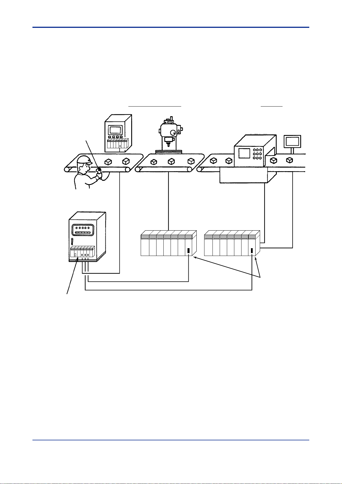
A1.2 Application Examples
If a remote I/O system is configured, some problems could occur, which include configuration (environment) setting, uses of specific remote I/O instructions, and I/O refresh time, or
the like.
Whereas if a remote I/O system is configured with a fiber-optic FA-bus module, the above
problems will not occur. The system configuration example is shown below.
Example of conveyer control:
Assembly and processing Inspection
Control panel
Test equipment
Bar-code reader
NC machine
A1-2
Conveyer control panel
FA-M3 main unit
Figure A1.1 System Configuration Example
RS-232-C
communication
interface
Fiber-optic FA bus
Fiber-optic FA bus
FA-M3 subunits FA-M3 subunits
Fiber-optic FA bus
GP-IB
interface
RS-232-C
communication
interface
Fiber-optic FA-bus module
FA0101.EPS
IM 34M6H45-01E
1st Edition : Feb.28,1999-00
Page 18

<Toc> <Ind> <A2. Specifications >
A2 . Specifications
A2.1 Function Specifications
■ General Specifications
Table A2.1 General Specifications
A2-1
Items
Current consumption 220 mA max. (5 V DC)
External dimensions 28.9 (W) × 100 (H) × 83.2 (D) mm
Weight 0.1 kg
Note: For other specifications, see applicable specifications for the FA-M3.
■ Communications Specifications
Table A2.2 Communications Specifications
Transmission speed 10 Mbps
Transmission media Two-conductor optical fiber (hard plastic clad quartz fiber H-PCF)
Transmission distance Max. total extension: 200 m
Max. interunit extension: 200 m
Transmission configuration Star configuration
Maximum number of subunits 7
connected
RAS functions • I/O contact shutdown due to a transmission channel error
• Error location reporting via a transmission channel
Specifications
F3LR01-0N
TA0201.EPS
SpecificationsItem
TA0202.EPS
A2.2 Operating Environment
No specific operating environmental limitations are required.
Logging of a transmission line error to an error log can be made either in the F3SP21,
F3SP25 or F3SP35 Module in Version 8 or later, or in the Ladder Diagram Support Program (M3) in Version 1.08 or later .
IM 34M6H45-01E 1st Edition : Feb.28,1999-00
Page 19

<Toc> <Ind> <A2. Specifications >
A2.3 Components and Their Functions
■ Front View
Indicators
RDY: Lit when the internal circuit is operating normally.
ERR: Lit when the module fails to detect an input signal from the port.
SUB UNIT
3
2
4
NO.
1
5
0
6
9
7
8
Unit No. Switch (SUB UNIT No.)
Set unit numbers 0 to 7:
0: Main unit number
1 to 7: Sub-unit numbers
7 to 9: Inhibited
A2-2
■ Right Side View
Figure A2.1 Locations of Components
Optical fiber port
FA0201-1.EPS
This figure shows where
the cover is removed.
Functions Set Switches
(4-pole DIP switch block)
Switch No. ON OFF Factory setting
1
Output
shutdown
Hold
ON
2
3
Always OFF.
4
(Valid only for the fiber-optic FA-bus modules that
are installed in a subunit.)
FA0201-2.EPS
IM 34M6H45-01E
1st Edition : Feb.28,1999-00
Page 20
<Toc> <Ind> <A2. Specifications >
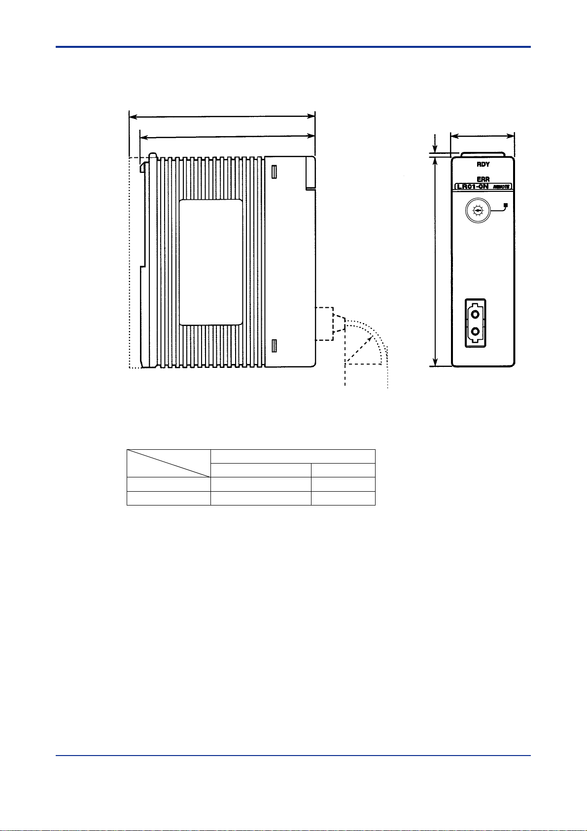
A2.4 External Dimensions
85.5
A2-3
(Unit: mm)
83.2 28.9
Figure A2.2 External Dimensions
2
SUB UNIT
3
2
4
NO.
1
5
0
6
9
7
8
100
r
FA0202.EPS
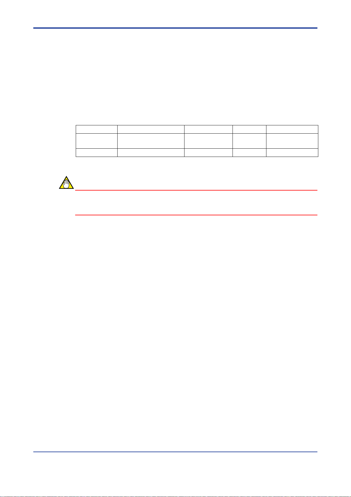
Allow for the following cable bending whenever the module is installed.
Table A2.3 Radius of Cable Bending
Radius (r) of cable bending, mm
During installation work When installed
Fiber optic cord 15 min. 50 min.
Fiber optic cable 50 min. 100 min.
TA0203.EPS
IM 34M6H45-01E 1st Edition : Feb.28,1999-00
Page 21

Blank Page
Page 22

<Toc> <Ind> <A3. System Configuration >
A3. System Configuration
A3.1 Fiber-optic FA-bus System Configuration
Fiber-optic FA-bus systems are so configured that fiber-optic F A-bus modules are installed
in main units and subunits, and the intermodules are connected with optical-fiber cables.
Main units: Units on which CPU modules are installed.
Sub units: Units for system expansion, on which CPU modules are not installed.
A3.1.1 Restrictions on System Configuration
Fiber-optic FA-buses are restricted in system configuration, as listed in Table A3.1.
Table A3.1 Restrictions on System Configuration
Item Specifications
Maximum total extension per system 200 m
No. of connectable subunits 7 max.
No. of fiber-optic FA-bus modules installable in main units
No. of fiber-optic FA-bus modules installable in subunits
Number of modules installable in subunits All I/O modules and special modules,
Unit no. setting Main unit: 0
(rotary switch on the module front panel) Subunit: 1 to 7 (no duplication allowed)
7 max.
1 max.
except FA link modules and Ethernet modules,
can be installed.
A3-1
TA0301.EPS
IM 34M6H45-01E 1st Edition : Feb.28,1999-00
Page 23
<Toc> <Ind> <A3. System Configuration >
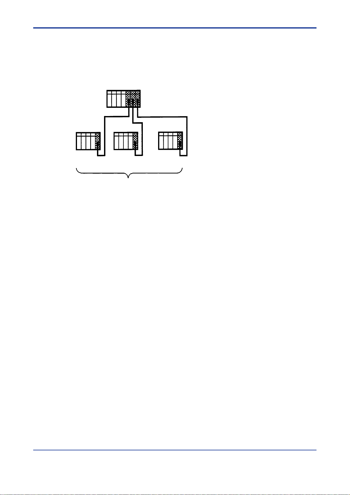
A3.1.2 Connecting Modules
The FA-M3 modules can be connected only in the star configuration as in Figure A3.1.
■ Star Configuration
A3-2
Unit No. 0
Unit No.1 Unit No.2 Unit No.3
Seven subunits max.
Figure A3.1 Connecting Modules
Main unit
FA0301.EPS
IM 34M6H45-01E 1st Edition : Feb.28,1999-00
Page 24

<Toc> <Ind> <A4. Preliminary Setting and Cable Connections >
A4. Preliminary Setting and Cable
Connections
A4.1 Startup Procedures
Figure A4.1 shows the system startup procedures when the fiber-optic FA-bus modules are
used.
Build-up system configuration
A4-1
Select an appropriate route for
laying fiber optic cables
Determine fiber optic cable
specifications and place an
order for cables
Carry out cable installation
Connect fiber optic codes or cables
Instrument layout
Set module setup switches
Refer to Sumitomo Electric
Industries, Ltd. Manual of how
to lay fiber optic cables.
Mount fiber-optic FA-bus
module on base module
Apply the power
Preliminary check
...
Refer to Sumitomo Electric
Industries, Ltd. Manual of how to
lay fiber optic cables.
(See Section A4.2)
(See Section A4.3)
(See Section A4.4)
(See Section A4.4)
Figure A4.1 System Startup Flow
Start operation
FA0401.EPS
IM 34M6H45-01E 1st Edition : Feb.28,1999-00
Page 25
<Toc> <Ind> <A4. Preliminary Setting and Cable Connections >
A4.2 Setting Switches
A4.2.1 Setting Unit Number Switches
Set the unit numbers for module installation using a decimal rotary switch on the front of the
module.
SUB UNIT
3
2
4
NO.
1
5
0
6
9
7
8
FA0402.EPS
Figure A4.2 Location of Unit Number Set Switch
A4-2
The unit number set ranges from 0 to 7 (see Note below). Do not duplicate unit numbers
with those of other fiber-optic FA-bus modules. Set unit number 0 to all modules installed
on the main unit.
Table A4.1 Setting Unit Number Switches
Setting switch Description
0 For modules installed on the main unit (default value: 0)
1 to 7 For modules installed on subunits
8 to 9 Not in use (prohibited)
TA0401.EPS
CAUTION
• If the unit numbers are duplicated, the fiber-optic FA-bus module will not operate
normally . Or if the module is accessed using a software package with the unit numbers duplicated, an RS-232-C communications error will occur and operation of that
package will stop.
• Do not install the F3LR01 module set as a subunit and a sequence CPU module on
the same base module. Otherwise, the sequence CPU module detects an error
causing its memory to clear.
IM 34M6H45-01E
1st Edition : Feb.28,1999-00
Page 26
<Toc> <Ind> <A4. Preliminary Setting and Cable Connections >
A4.2.2 Setting Functional Set Switches
A 4-bit DIP switch is provided on the right side of the module for functional features. Using
this switch, set the following:
■ Setting Output Shutdown During a Communications Error
Use SW1 for this setting. This switch is valid only for subunits. Use the switch in the off
position for the main unit (set to on at the factory).
For details on the output shutdown features, see Chapter A7, “RAS Function.”
Table A4.2 Setting Functional Set Switches
Switch numbers Functions ON OFF Factory setting
1 Output shutdown Hold On
2 to 4 * Not in use — Off
CAUTION
Output shutdown during
communications error
A4-3
TA0402.EPS
Use switches 2 through 4 set to off. If these switches remain on, the module will not operate
correctly .
IM 34M6H45-01E
1st Edition : Feb.28,1999-00
Page 27

<Toc> <Ind> <A4. Preliminary Setting and Cable Connections >
A4.3 Attaching and Detaching Modules
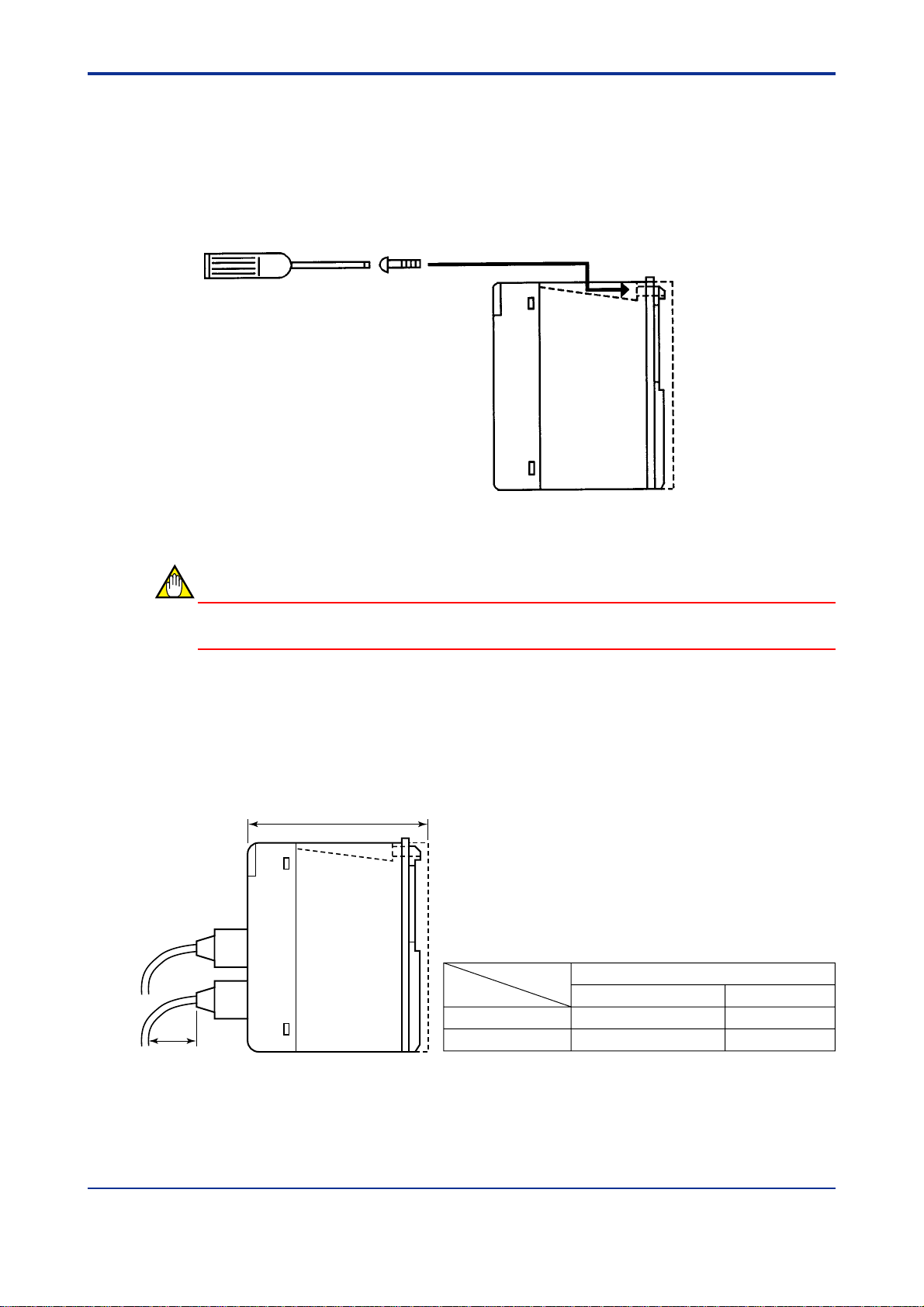
A4.3.1 Attaching Modules
Figure A4.3 shows how to attach this module to the base module. First hook the anchor
slot at the bottom of the module to be attached onto the anchor pin on the bottom of the
base module. Push the top of this module in the direction of the arrow shown in the figure
(toward the base module) until the yellow, spring-loaded anchor/release button clicks into
place.
Base module
Top button
Anchor pin
A4-4
This module
Figure A4.3 Attaching Modules
CAUTION
DO NOT bend the connector on the rear of the module by force during the above operation.
If the module is forcibly pushed with an improper connection, the connector may bend and
this damage will cause a module installation error during the self-diagnosis.
A4.3.2 Detaching Modules
T o remove this module from the base module, reverse the above operation by pressing the
yellow anchor/release button to unlock it, and tilting the module away from the base module. Then lift the module off of the anchor pin at the base.
FA0403.EPS
IM 34M6H45-01E
1st Edition : Feb.28,1999-00
Page 28
<Toc> <Ind> <A4. Preliminary Setting and Cable Connections >
A4.3.3 Attaching Modules in Intense Vibration Environments
If the modules are used in intense vibration environments, fasten the modules with a screw
directly beneath the yellow anchor/release button, as shown in Figure A4.4. For this, use a
12- to 14-mm long M4 binder screw. With a Phillips screwdriver , tighten the upper side of
the module with this screw. During this operation, the user must tilt the screwdriver somewhat using the guide channel at the top of the module. Allow a clearance of such an extent
that the screwdriver will access the screw, between the module and the duct above it.
FA0404.EPS
Figure A4.4 Tightening Module
A4-5
CAUTION
DO NOT overtighten the module fixing screw .
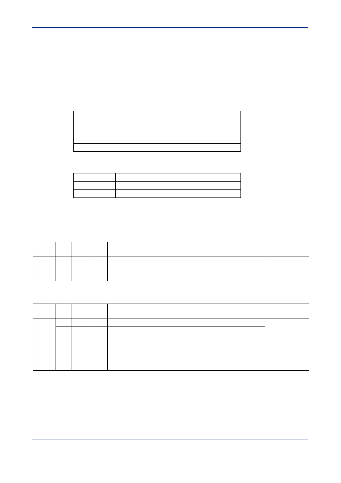
A4.3.4 Depth of Installation
The module’s installation depth is 85.5 mm-long between the rear of the base module and
the front of this module. However, if a cable with connectors is used, some extra space in
addition to this overall depth must be provided for the bend in the cable.
85.5
r
Figure A4.5 Installation Depth
Radius (r) of cable bending, mm
During installation work After installation
Fiber optic cord 15 min. 50 min.
Fiber optic cable 50 min. 100 min.
FA0405.EPS
IM 34M6H45-01E 1st Edition : Feb.28,1999-00
Page 29
<Toc> <Ind> <A4. Preliminary Setting and Cable Connections >
A4.4 Connecting Fiber Optic Cables
A4.4.1 Preparation for Calbes
Connect fiber optic cables between fiber-optic FA-bus modules.
(1) Specifications for fiber optic cables used
Table A4.3 Fiber Optic Cable Core Specifications
Item Specifications
Model HC-20/07 (manufactured by Sumitomo Electric)
Core diameter 200 ±5 µm
Clad diameter 230 µm
Transmission loss 7 dB/km max. (λ = 0.81 µm, Ta = 25°C) (HC)
Table A4.4 Fiber Optic Connector Specifications
Model Number Specifications
CF-2001H Bi-directional, lever-lock, adhesive and polishing
CF-2011 B-directional, lever-lock, pressurizing and cutting
+0
–10
TA0403.EPS
TA0404.EPS
A4-6
(2) Fiber optic cables supplied by the company
Fiber Optic Cable (for Panel Use)
Sufix
Style
Model
KM60
Code
-S60 — — For connections inside panels, cable length up to 0.6 m
-001 — — For connections inside panels, cable length up to 1 m
-003 — — For connections inside panels, cable length up to 3 m
Fiber Optic Cable (for Indoor Use) with Tension Members
Model
KM61
Sufix
Code
-010 — — For indoor connections, cable length up to 10 m
-100 — — For indoor connections, cable length up to 100 m,
-150 — — For indoor connections, cable length up to 150 m,
-200 — — For indoor connections, cable length up to 200 m,
Option
Code
Code
Note: For pulling eyes, see the pulling-eye assembly diagram later in this manual.
Style
Code
Option
Code
with a pulling eye (one end of the cable)
with a pulling eye (one end of the cable)
with a pulling eye (one end of the cable)
Description
Description
Applicable
Module
F3LR02
and
F3LP12
TAC040401_1.EPS
Applicable
Module
F3LR02
and
F3LP12
TAC040401_2.EPS
IM 34M6H45-01E 1st Edition : Feb.28,1999-00
Page 30

<Toc> <Ind> <A4. Preliminary Setting and Cable Connections >
Fiber Optic Cable (for Outdoor Use) with Tension Members
Sufix
Style
Model
KM62
KM67
Code
-100 — — For outdoor connections, cable length up to 100 m,
-200 — — For outdoor connections, cable length up to 200 m,
-300 — — For outdoor connections, cable length up to 300 m,
-400 — — For outdoor connections, cable length up to 400 m,
-500 — — For outdoor connections, cable length up to 500 m,
-600 — — For outdoor connections, cable length up to 600 m,
-700 — — For outdoor connections, cable length up to 700 m,
-800 — — For outdoor connections, cable length up to 800 m,
-900 — — For outdoor connections, cable length up to 900 m,
-L01 — — For outdoor connections, cable length up to 1000 m,
-300 — — For outdoor connections, cable length up to 300 m,
-400 — — For outdoor connections, cable length up to 400 m,
-500 — — For outdoor connections, cable length up to 500 m,
Code
Option
Code
Description
with a pulling eye (one end of the cable)
with a pulling eye (one end of the cable)
with a pulling eye (one end of the cable)
with a pulling eye (one end of the cable)
with a pulling eye (one end of the cable)
with a pulling eye (one end of the cable)
with a pulling eye (one end of the cable)
with a pulling eye (one end of the cable)
with a pulling eye (one end of the cable)
with a pulling eye (one end of the cable)
with a pulling eye (one end of the cable)
with a pulling eye (one end of the cable)
with a pulling eye (one end of the cable)
Note: For pulling eyes, see the pulling-eye assembly diagram later in this manual.
A4-7
Applicable
Module
F3LR02
(up to 200 m)
F3LP12
(up to 1000 m)
F3LR02
(up to 500 m)
TAC040401_3.EPS
IM 34M6H45-01E 1st Edition : Feb.28,1999-00
Page 31

<Toc> <Ind> <A4. Preliminary Setting and Cable Connections >
■ Outline Drawing (with dimensions)
KM60
Fiber optic connector Fiber optic connector
ID marking ID marking
Fiber optic cable
A4-8
Cable Length (L)
L≤5
KM61, KM62, KM67
Fiber optic connector ID marking
Cable Length (L)
5<L≤30
30<L
Tolerance +e (m)
0.20
ID marking
(Sheathless
terminal)
Tension
member
Tolerance +e (m)
0.50
L × 0.03 (3%)
L + tolerance
Tape or
protective covering
Fiber optic cable
L + tolerance
+e
–0
+e
–0
(Sheathless
terminal)
Tension
member
FAC040401_1.EPS
Fiber optic connector
200±50 mm200±50 mm
FAC040401_2.EPS
■ Corss-sectional Drawing
KM60
1
2
3
4
5
ID marking
1 Core (silica glass)
2 Clad (fluoroacylate resin)
3 Covering (fluorine resin)
4 Reinforcing material
(aromatic high-tensile-strength fiber)
5 Sheath (heat-resistant PVC, black)
FAC040401_3.EPS
IM 34M6H45-01E 1st Edition : Feb.28,1999-00
Page 32

<Toc> <Ind> <A4. Preliminary Setting and Cable Connections >
KM61, KM62, and KM67
A4-9
1
2
3
4
5
6
1 Fiber optic single-core cable
2 Tension member (plastic-covered copper wire)
3 Lacing (plastic lacing)
4 Inclusion (plastic yarn or fiber)
5 Holding tape (plastic fiber)
6 Heat-resistant PVC sheath (KM61), LAP sheath (KM62, KM67)
Fiber optic lead-in cable laying pulling-eye assembly diagram
15-mm
30
dia.
2-mm
dia.
6
1
Rigid section 70
6
3
78
Approx. 500
Rigid section 50
2
(3) Fiber optic cables from Sumitomo Electric Industries, Ltd.
FAC040401_4.EPS
Unit: mm
4
5
FAC040401_5.EPS
Manufacturer Type Specifications Applicable modules
Sumitomo
Electric
Industries, Ltd.
Fiber optic cord H-PCF2-core cord
Fiber optic cable 2-C-V (indoor use)
2-C-LAP (outdoor use)
DCV-HC-20/07
2 × CCV-HC-20/07
2 × CCV-HC-20/07
F3LR01, F3LR02, and F3LP12
F3LR01, F3LR02, and F3LP12
F3LR01, F3LR02, and F3LP12
TAC040401_4.EPS
Fiber optic cord and cable with connectors attached at both ends
Manufacturer Product Type Specifications P: L (m) Shape Applicable modules
Sumitomo
Electric
Industries,
Ltd.
2001H-MM-L
2001H-MM-0.2-L
2001H-MM-0.2/L
1: Modules and distance F3LR01 and F3LR02, 0 to 200 meters
*
2: Polling-eye: Use a polling eye for the cable length of 50 meters or above.
*
Fiber Optic Cord
2-C-V cable
(for indoor use)
2-C-LA cable
(for outdoor use)
F3LR12, 0 to 1000 meters
DCV-HC-20/07
2 × CCV-HC-20/07
2 × CCV-HC-20/07
-P
-P
2
*
2
*
Up to 5
1
*
1
*
2.2-mm dia. ×
2-core cord
8.4-mm dia. cable
10-mm dia. cable
F3LR01, F3LR02,
and F3LP12
F3LR01, F3LR02,
and F3LP12
F3LR01, F3LR02,
and F3LP12
TAC040401_5.EPS
CAUTION
For more details on fiber optic cables, contact Sumitomo Electirc Industries, Ltd. When
ordering, specify the above shaded areas.
1
*
1
*
1
*
IM 34M6H45-01E 1st Edition : Feb.28,1999-00
Page 33

<Toc> <Ind> <A4. Preliminary Setting and Cable Connections >
CAUTION
Be sure to use the specified cables, otherwise, the module may fail, or expected design
performance cannot be attained.
(4) Firber optic cables and tools required
When laying fiber optic cables, use Sumitomo Electric cables listed below.
Table A4.5 Fiber Optic Cables and Tools Required
Name Model
Fiber optic connector Adhered, polished and assembled CF-2001H
Pressurized, cut and assembled CF-2011
Toof for fiber optic connector Pressurizing, cutting and assembling CAK-1062
Optical power tester (for fiber optic connector inspection) CAT-2700
Master fiber set (for fiber optic connector inspection) CAT-2001H
Note: For the fiber optic cable installation, consult the Fiber Optic Installation Instructions (publication number IM 34M6C92-
01E).
A4-10
CAT2001H (HG)
TA0405.EPS
CAUTION
Use the specified cable connectors and tools, otherwise the module may fail or expected
disign performance cannot be attained.
IM 34M6H45-01E 1st Edition : Feb.28,1999-00
Page 34

<Toc> <Ind> <A4. Preliminary Setting and Cable Connections >
A4.4.2 Attaching and Detaching Connectors
■ Attaching Connectors
When completing an optical connection, always hold the connector and never the cable,
then insert it until it clicks into place. Then pull it slightly toward you to make sure that the
connector is correctly seated.
Fiber optic connector
FA0406.EPS
Figure A4.6 Attaching Connectors
A4-11
■ Detaching Connectors
FA0407.EPS
Figure A4.7 Detaching Connectors
Hold the center portion of the connector (indicated by the arrow in the figure) to unlock
connector and then pull it toward you.
IM 34M6H45-01E 1st Edition : Feb.28,1999-00
Page 35

<Toc> <Ind> <A4. Preliminary Setting and Cable Connections >
A4.4.3 Notice on Connecting Fiber Optic Connectors
Handle fiber optic cables with great care. When the fiber optic cables are laid, first read
Sumitomo Electric Industries Manual and then ask the workers for specific applications as
described in the manual.
CAUTION
• DO NOT touch optical connector core wires and protect them from dirt and dust.
Otherwise, transmission performance may deteriorate or a communications error
could occur.
T o store them, be sure that they are provided with appropriate cable covers.
• Each time the fiber optic cords or cables are connected, keep the cable extension
within 0.7% of permissible extension percentage. When the cable is fixed, also keep
the cable extension within 0.2% of permissible extension percentage. If the cable
extension is beyond these limitations, fiber optic cables or cords may be disconnected.
For this purpose, DO NOT cause excess tension, bending, or twisting or the like of the
cables or cords.
Table A4.3 General Mechanical Characteristics for Fiber Optic Codes and Cables
Tensile strength
Fiber optic cord During wiring<10 15 min. during wiring 0 kg <180°/2 m
When fixed = 0 50 min. when fixed
Fiber optic cable During wiring< 50 50 min. during wiring 100 kg/50 mm <90°/2 m
When fixed< 0 100 min. when fixed
Bend radius (mm) Lateral pressure Twisting
A4-12
TA0406.EPS
For the tension during wiring work, follow the allowable tensile strength specified by optical
fiber specifications or sales brochures.
When fixing cables, DO NOT create excess tension to connectors and cables.
Use a pressurizing and cutting type connector in the field work.
IM 34M6H45-01E
1st Edition : Feb.28,1999-00
Page 36

<Toc> <Ind> <A4. Preliminary Setting and Cable Connections >
A4.5 Preliminary Checks
After installing modules and wiring fiber optic cables, check that all electrical connections
have been completed and the modules are in communications-enabled states.
Apply power to the units and check the following two points:
(1) Check that the RDY (green) lamp lights up.
If this lamp does not light up, the fiber-optic FA-bus module may not be connected to
the base module correctly . T urn off the power and attach the module to the base
module correctly . Then apply the power and be sure that the RDY lamp lights up.
(2) Check that the ERR lamp remains turned off.
If the lamp lights up, communications will be disabled. If the power of the destination
unit is off, turn on its power and check that the ERR lamp is turned off. If it is still on,
transmission lines may be faulty . (Fiber optic cables may be disconnected).
A4-13
IM 34M6H45-01E
1st Edition : Feb.28,1999-00
Page 37

Blank Page
Page 38

<Toc> <Ind> <A5. Accessing the Module in the Subunit >
A5. Accessing the Module in the Subunit
A5.1 Slot Numbers of FA-M3
Slot numbers are used for accessing each module in the FA-M3.
These slot numbers indicate the position of the slot where the module is mounted and
consist of 3-digit integers as shown below.
1
Slot number within the unit
*
: 01 to 16
1 Sequentially from slot right of power
*
supply module, 01, 02, ......, 16
A5-1
Unit number main unit: 0
subunit: 1 to 7
FAC0501.EPS
Accessing modules mounted in the subunit is similar to that for modules mounted in the
main unit and can be accomplished by either a ladder diagram support program or a
BASIC program.
IM 34M6H45-01E 1st Edition : Feb.28,1999-00
Page 39

<Toc> <Ind> <A5. Accessing the Module in the Subunit >
Optical bus module
A5-2
Up to 7
units can be
connected
Slot number→
Main unit
Subunit 1
Subunit 2
001 002 003 004 005 006 007 008 009 010 011 012 013 014 015 016
Power
supply
module
Add-on sequence CPU
(3 CPUs maximum)
CPU module
101 102 103 104 105 106 107 108 109 110 111 112 113 114 115 116
Power
supply
module
201 202 203 204 205 206 207 208 209 210 211 212 213 214 215 216
Power
supply
module
.
.
.
.
.
.
.
.
701 702 703 704 705 706 707 708 709 710 711 712 713 714 715 716
Power
Subunit 7
supply
module
Figure A5.1 System Configuration and Slot Numbers
FA0501.EPS
IM 34M6H45-01E 1st Edition : Feb.28,1999-00
Page 40

<Toc> <Ind> <A6. I/O Refresh Time >
A6. I/O Refresh Time
A6.1 Estimation of I/O Refresh Time
Calculate the I/O refresh time separately for each port of the main unit.
For details, refer to the following calculation example.
A6-1
I/O refresh time =
• There are two types, namely, ‘input read’ and ‘output write.’
Calculate the I/O refresh time for each type using the following
formula and sum the values.
I/O refresh time for each
access
‘Access type’ ‘Formula’
F3SP21 F3SP25/35
Input read 11 µs 10 µs
Output read 27 µs 21 µs
=+
Sum of I/O refresh times
for each access
Time dependent on acces
• 1.0 µs ×
Time dependent on
transmission distance
ø (m)
100 (m)
ø: Transmission distance
Number of modules
×
converted to 16 points
‘Number of modules’
• Number of modules
corresponding to access type,
convert to a 16-point module.
FAC0601.EPS
IM 34M6H45-01E 1st Edition : Feb.28,1999-00
Page 41

<Toc> <Ind> <A6. I/O Refresh Time >
A6.2 I/O Refresh Time Calculation Example
Calculate I/O refresh time for the following system configuration.
A6-2
Main unit F3LR01-0N
module
Figure A6.1 Example of Calculation of I/O Refresh Time (for F3SP25 and F3SP35 Modules)
Master CPU
Power
supply
150 m
Subunit 1
Input 32-point module × 2
Output 32-point module × 1
FA0601.EPS
[Step 1] Calculating the time dependent on transmission distance
• 1.0 µs × = 1.5 µs
150 (m)
100 (m)
FAC0602_1.EPS
[Step 2] Calculate the number of modules, converted to 16 points
• Input read = 32 points × 2 → 2 × 2 = 4
• Output write = 32 points × 1 → 2 × 1 = 2
[Step 3] Calculating the total I/O refresh time
Input read = (10 µs +1.5 µs) × 4 = 46.0 µs
Output write = (21 µs +1.5 µs) × 2 = 45.0 µs(+
I/O Refresh Time = 91.0 µs
FAC0602_2.EPS
IM 34M6H45-01E 1st Edition : Feb.28,1999-00
Page 42

<Toc> <Ind> <A7. RAS Function >
A7. RAS Function
A7.1 Function for Detecting an Error Location
A7.1.1 Check the LED Display
When an error occurs in this module or when there is a cable break in the transmission line,
the error LED (ERR) or alarm LED (ALM) of the CPU module turns on.
The LED of this CPU module turns on, even when an error occurs in a module other than
this module.
To decide whether the cause of the lighted LED lies in this module, check the status of the
RDY and ERR LEDs of the Fiber-optic F A-bus module mounted on each unit.
The relation between the fiber optic cable break and the lighting of the LED in the module is
as shown below.
A7-1
[Disconnection example 1]
CPU MODULE
ERR ON
ALM ON
MAIN UNIT
Cable disconnected
Fiber-optic FA-bus module
ERR ON
Subunit
×
0
[Disconnection example 2]
[Disconnection example 3]
Figure A7.1 Relation between Fiber Optic Cable Break and Lighting of LED in the Module
CPU MODULE
ERR ON
ALM ON
Main unit
Fiber-optic
FA-bus module
ERR ON
0
CPU MODULE
ERR ON
ALM ON
Main unit
Fiber-optic
FA-bus module
ERR ON
0
×
Cable disconnected
×
×
1
Subunit
1
Cable disconnected
Optical FA Bus module
ERR ON
Subunit
1
FA0701.EPS
IM 34M6H45-01E 1st Edition : Feb.28,1999-00
Page 43

<Toc> <Ind> <A7. RAS Function >
A7.2 Output Shutdown Function due to a
Communications Error
A7.2.1 Overview of Output Shutdown Function
This module is equipped with a function which shuts down the output of the I/O module
when a communications error occurs.
When an error occurs in the fiber-optic FA-bus module, this function prevents it from af fecting the system or from resulting in hazardous operation or unstable operation of the system.
For example, when the transmission line breaks, it detects the error and immediately turns
off the output signals of each I/O module and avoids any risk.
The output shutdown function on a communications error is valid only on configurations
having one main CPU (with no add-on CPU).
A7.2.2 Output Shutdown of Subunit
A7-2
Subunit
CAUTION
• When it is necessary to reset the output due to power supply breakdown or transmission line error, use the output module with less than 32 points, turn on the shutdown
switch of the F3LR02 and set an Output Reset using the CPU configuration setting.
This setting cannot be used in a 64-point output module.
• When it is necessary to hold the output due to power supply breakdown and transmission line error, turn of f the shutdown switch of the F3LR02 and set an Output Hold
using the CPU configuration setting.
• The Output Reset function cannot be used in multiple CPU systems (systems loaded
with add-on CPU). Always use the Output Hold setting.
The operation of the output module corresponding to various combinations of setting is
shown below for your reference.
Shutdown SW of
F3LR01 mounted
in Subunit
ON Reset Short-circuited Open Reset Hold
OFF Reset Open Short-circuited Hold Hold
Configuration
Setting of
CPU module
Hold Short-circuited Open Hold Hold
Hold Open Short-circuited Hold Hold
Fail signal contact point Output module operation
FAIL 1 FAIL 2 32 points or less 64 points
TAC070202.EPS
IM 34M6H45-01E 1st Edition : Feb.28,1999-00
Page 44

<Toc> <Ind> <A7. RAS Function >
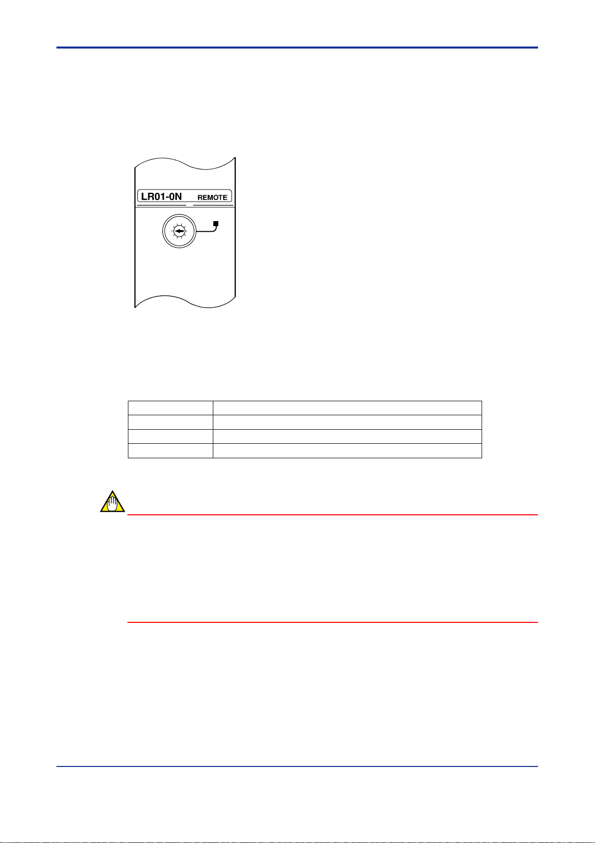
A7.2.3 Function Setting Operation Procedure
The procedure for using the output shutdown function for a communications error is shown
below.
[Step 1] Operating the function set switch on the right side of the module.
Function set switch
In order to operate this function, it is necessary to
set the function set switch on the right side of this
module mounted in the subunit. Turn the first bit
of the 4-bit DIP switch “ON” (It is already set to
ON at the time of shipment from the factory).
FA0702.EPS
Figure A7.2 Function Set Switch on the Right Side of the Module
[Step 2] Output during halt
A7-3
■ Setting the input/output conditions using the Ladder Diagram Support
Program M3
Setting is performed using the Ladder Diagram Support Program M3 for the FA-M3.
This method carries out the DIO settings using the Ladder Diagram Support Program M3
on a personal computer. The outline of the operation is as follows:
1. Select the configuration from the top level menu (initial menu) of the Ladder Diagram
Support Program M3.
2. Select the DIO definition in the configuration.
3. On the DIO Definition screen, set the output during halt item of the respective I/O
module to the reset.
IM 34M6H45-01E 1st Edition : Feb.28,1999-00
Page 45

<Toc> <Ind> <A7. RAS Function >
Configuration Configuration name: D:\TOOL\CONFIG
DI/O setting Base unit 1
BIN/BCD 17-32 BIN BCD BIN/BCD 17-32 BIN BCD
1 Input sampling 01-16 16 1.0 3 Input sampling 01-16 16 1.0
(ms) 17-32 16 1.0 (ms) 17-32 16 1.0
Output during halt Reset Hold Output during halt Reset Hold
BIN/BCD 17-32 BIN BCD BIN/BCD 17-32 BIN BCD
2 Input sampling 01-16 16 1.0 4 Input sampling 01-16 16 1.0
(ms) 17-32 16 1.0 (ms) 17-32 16 1.0
output during halt Reset Hold Output during halt Reset Hold
KEY IN:
Capacity
Trace
Run
Comm
01-16 BIN BCD Unused 01-16 BIN BCD Unused
33-48 BIN BCD 33-48 BIN BCD
49-64 BIN BCD 49-64 BIN BCD
33-48 16 1.0 33-48 16 1.0
49-64 16 1.0 49-64 16 1.0
01-16 BIN BCD Unused 01-16 BIN BCD Unused
33-48 BIN BCD 33-48 BIN BCD
49-64 BIN BCD 49-64 BIN BCD
33-48 16 1.0 33-48 16 1.0
49-64 16 1.0 49-64 16 1.0
Register
ROM
FALink NextUnit Previous Default ExitDIO
A7-4
SC0701.EPS
Screen A7.1 Setting of Input/Output Conditions in Ladder Diagram Support Program M3
Further, for details on the Ladder Diagram Support Program M3 and similar operations,
refer to the ‘Ladder Diagram Support Program M3 Instruction Manual’ (publication number
IM 34M6Q13-01E).
IM 34M6H45-01E 1st Edition : Feb.28,1999-00
Page 46

<Toc> <Ind> <A7. RAS Function >
■ Setting the input/output conditions using BASIC (F3BP20)
When an error occurs, ‘Do you want to hold output status of the output module’ or ‘Do you
want to reset’ is set using a CONTROL statement.
For 16-point and 32-point modules, setting can be performed every 8 terminals within the
control register.
The format of the statement is as follows:
A7-5
Format
CONTROL m, 1 : I
m: Slot number or numerical expression
I: Set data, integer or integer variable
Contents of control register
MSB LSB
15 12 8 4 0
Register 4 Register 3 Register 2 Register1
Not in use (usually 0)
Status setting on master CPU error,
on startup
(0: hold, 1: Reset)
Register 4: Terminals 25 to 32
Register 3: Terminals 17 to 26
Register 2: Terminals 9 to 16
Register 1: Terminals 1 to 8
• All the contents of the control register are “0” when the modules starts up.
Example CONTROL 206 , 1: $0010
: For the output module in slot number 206, when
there is a master CPU error, terminal numbers
9 to 16 are reset but status of the remaining
terminals is maintained.
IM 34M6H45-01E 1st Edition : Feb.28,1999-00
FAC070203.EPS
Page 47

Blank Page
Page 48

<Toc> <Ind> <A8. Error Handling >
A8. Error Handling
A8.1 Troubleshooting
If a problem occurs in this module, follow the troubleshooting flowchart below to solve the
problem.
CPU module ALM on
A8-1
Error in this module?
YES
Is ‘RDY’ LED of
this module on?
YES
Is ‘ERR’ LED of
this module on?
NO
Is unit number
setting correct?
NO
NO
YES
NO
Investigate the reason
why the ‘ALM’ LED of
a module is on and
take countermeasures.
Refer to A8.2,
“Procedure Flowchart”
when ‘RDY’ LED is
not on.
Find out the place of
breakdown referring to
the procedure in
Section A7.1, “Function
for Detecting an Error
Location.”
Refer to A8.3, “Flow
Chart when ‘ERR’
LED is on.”
YES
Is setting of
switch in the side
cover correct?
YES
Replace this module.
END
NO
Set the switch inside
Figure A8.1 Troubleshooting Flowchart (1)
Set the unit number
correctly.
the right side cover
correctly (SW 2 to 4
are off).
FA0801.EPS
IM 34M6H45-01E 1st Edition : Feb.28,1999-00
Page 49

<Toc> <Ind> <A8. Error Handling >
A8.2 Troubleshooting Flowchart When ‘RDY’ LED Is
Not ON
‘RDY’ LED is not on
A8-2
Is power
supply module being
supplied prescribed
voltage?
YES
Are other modules
in RDY state?
YES
Is it mounted in
proper slot?
YES
Does ‘RDY’
LED remain off even
if it is mounted
in another
slot?
YES
NO
Supply normal voltage.
NO
Replace power supply
module or base module.
NO
Push it in the slot till
‘click’ sound is heard
(refer to A4.3 of
this manual).
NO
NO
Is ‘RDY’ LED on?
Replace base module.
YES
Replace the module.
Figure A8.2 Troubleshooting Flowchart (2)
END
FA0802.EPS
IM 34M6H45-01E 1st Edition : Feb.28,1999-00
Page 50

<Toc> <Ind> <A8. Error Handling >
A8-3
A8.3 Troubleshooting Flowchart When ‘ERR ’ LED Is
ON
‘ERR’ LED on
Is optical fiber
connected?
YES
Is the power
supply of all other
units turned on?
YES
Is optical fiber
disconnected?
NO
Is setting of switch
in the side cover
correct?
YES
NO
Connect optical fiber.
NO
Turn on the power
of all the other units.
YES
Replace optical fiber.
NO
Set switch inside the
right side cover correctly
(SW 2 to 4 are off).
Replace this module.
Is ‘ERR’ LED still on?
NO
END
YES
Figure A8.3 Troubleshooting Flowchart (3)
FA0803.EPS
IM 34M6H45-01E 1st Edition : Feb.28,1999-00
Page 51

Blank Page
Page 52

F3LR02-0N
Fiber-optic FA-bus Type 2 Module
IM 34M6H45-01E 1st Edition : Feb.28,1999-00
Page 53

Blank Page
Page 54

<Toc> <Ind> <B1. Overview >
B1. Overview
The Model F3LR02-0N Fiber-optic FA-bus T ype 2 Modules are interface modules to configure the distributed control system through a type 2 fiber-optic FA bus. This bus connects
FA-M3 main units and sub-units. Using this bus, users can configure a remote I/O system
efficiently.
If the above modules are installed on the FA-M3 main units and sub-units, and connected
with each other with an optical fiber cable, modules in the subunits will be handled at the
same level as in the main units.
1: I/O implies “Input” and “Output,” -- stated as “contact input/output.”
*
This module is mainly used for:
• Distributed installations of I/O modules
• System expansion
B1-1
*
1
CPU Module
Power Supply Module
Main units Subunits
Figure B1.1 Remote I/O System
Fiber-optic
FA-bus Type 2 Module
Power Supply Module
Fiber optic cable
Fiber-optic
FA-bus Type 2 Module
IM 34M6H45-01E 1st Edition : Feb.28,1999-00
Page 55

<Toc> <Ind> <B1. Overview >
B1.1 Features
Features included in this module are:
• High-speed communications
10 Mbps high-speed communications. These relieve the user from worrying about the I/O
refresh time in ladder programming.
• Extended inter-station distance
1
*
The master station can control substations
meters
*2
apart as indicated in the figure below. A maximum cable extension of 1.4 km
available.
which are at a maximum distance of 500
B1-2
3
*
is
Master station
500 m max.
Substation 1 Terminal station
1.4 km max.
● Freely substitutable installation
Except for the FA-link and Ethernet modules, other I/O modules can be installed as substa-
4
*
tions
. Access to modules is the same as access to modules installed on master stations.
● Easy installation
Unlike that of a remote I/O, installation requires no environmental (configuration) settings.
● Use of optical transmission signals
The fiber optic cable in the signal transmission line is not affected by noise on the line.
Master station Substation
Fiber-optic cable
1 Subunit on which this module is installed
*
2 If modules are to be installed more than 200 meters apart, use a Type GI H-PCF fiber optic cable.
*
3 In the daisy chain configuration with three substations.
*
4: FA Link and Ethernet Modules are not included.
*
● Versatile system configurations
Two I/O ports provided on the module allow daisy-chaining and loop connections. Installation of multiple T ype 2 Fiber-optic F A-bus modules enables a variety of configurations. For
more details on this, see Section B3.1.3 later in this manual.
● Multiple distributed system installations
A maximum of 56 substations or 32 substations* for each system is available.
For applications where only F3BU04 modules are used.
*
IM 34M6H45-01E
1st Edition : Feb.28,1999-00
Page 56

<Toc> <Ind> <B1. Overview >
1
● RAS
The alarm monitor
*
functions -- help pinpoint a trouble spot quickly.
2
*
and error logging
2
*
features allow you to localize a disconnection or a
trouble spot. Once an error is detected, an ERR LED lights up to indicate a failure even in
the field. For more details, see Chapter B6, "RAS Function."
1: RAS stands for "Reliability, A vailability, Serviceability" to indicate how easy it is to use the automatic equipment.
*
2: Indicates specific features in the Ladder Diagram Support Program M3.
*
B1-3
IM 34M6H45-01E
1st Edition : Feb.28,1999-00
Page 57

Blank Page
Page 58

<Toc> <Ind> <B2. Specifications >
B2 . Specifications
B2.1 Function Specifications
■ General specifications
Table B2.1 General Specifications
Item
Current consumption 460 mA max. (5V DC)
External dimensions 28.9 (W) 3 100 (H) 3 83.2 (D) mm
Weight 0.12 kg
■ Communications specifications
Specifications
F3LR02-0N
B2-1
Table B2.2 Communications Specifications
Item Specifications
Transmission speed 10 Mbps
Transmission media 2-conductor optical fiber (hard plastic clad quartz fiber H-PCF)
Transmission distance
Transmission configuration Star, daisy-chained or loop configuration
Maximum number of substations 56 stations
RAS features
Signal code Manchester code
I/O system Direct access to I/O
Number of I/O ports 2
1: A maximum of three stations available in daisy-chained interconnections.
*
2: A maximum of 32 stations per system available if all the F3BU04 subunits are connected.
*
500 m max. interunit extension
1.4 km total length
• I/O contact output shutdown due to a transmission channel error
• Error location reporting via transmission channel, and loop-back
functions
B2.2 Operating Environment
CPU modules that can be used with this module are:
F3SP21, F3SP25, F3SP35, F3BP20, and F3FP36.
1
*
2
*
IM 34M6H45-01E 1st Edition : Feb.28,1999-00
Page 59

<Toc> <Ind> <B2. Specifications >
B2.3 Components and Their Functions
■ Front view
B2-2
RDY
ERR1
ERR2
LR02-0N
3
2
4
1
5
0
6
9
7
8
4
5
3
6
2
7
1
8
9
0
A
F
B
E
C
D
1
2
■ Right side view
REMOTE
SUB UNIT
NO.
LEFT SLOT
NO.
Indicators : RDY : Lit when the internal circuit is
operating normally.
ERR1 : Lit when the module fails to detect an
input signal from port 1.
ERR2 : Lit when the module fails to detect an
input signal from port 2.
Unit number switch (SUB UNIT NO.) :
Sets a unit number 0 to 7.
0 : Main unit number
1 to 7 : Subunit numbers
8 and 9 : Inhibited.
(Default value: 0)
Slot number switch (LEFT SLOT NO.)
Sets the left slot number of the base module on which this module is
installed.
(Default value: 1)
1, 3, 5, 7, 9, B, D and F: Slot numbers for F3BU04 module
1 and 9: Slot number for F3BU06 module
1: Slot number for base module
(F3BU09 or F3BU13)
Optical-fiber port
Status set switch
SW
Meaning
No.
1
*
Action in
1
communication
error occurrence
2
Port used
3
Channel
configuration
4
RearFront
Reserved
1: Valid only for the output modules in a subunit.
*
2: Both port 1 and port 2 are used.
*
ON OFF
Hold
Port 1
Daisy
chain/start
configuration
—
Shutdown
Both ports
Loop
configuration
—
2
*
Factory
set
ON
OFF
OFF
OFF
This figure is drawn with the
cover removed.
1
OFF
2
3
4
5
OFF
6
7
8
Functions set DIP switch
Quantity-of-light set switch
SW
No.
5
6
7
8
Meaning
Port 1 light
power
setting
Port 2 light
power
setting
Station-to-station distance
(fiber-optic cable length) (m)
OFF
0 to
200
OFF
OFF
OFF
0 to
200
OFF
OFF
ON
ON
200
to
300
200
to
300
OFF
OFF
Figure B2.1 Components on the Front and Right Side of F3LR02-0N Module
IM 34M6H45-01E
300
ON
to
ON
ON
ON
400
300
ON
to
ON
400
1st Edition : Feb.28,1999-00
400
to
500
400
to
500
Page 60

<Toc> <Ind> <B2. Specifications >
B2.4 External Dimensions
■ External dimensions
LR02-0N
1
0
1
0
1
2
9
8
4
3
2
F
E
D
RDY
ERR1
ERR2
3
5
C
SUB UNIT
4
NO.
5
6
7
LEFT SLOT
6
NO.
7
8
9
A
B
B2-3
Unit: mm
REMOTE
r
Figure B2.2 External Dimensions of F3LR02-0N Module
Allow for the following cable bending whenever the module is installed.
Table B2.3 Radius of Cable Bending
Radius (r) of cable bending, mm
During installation work When installed
Fiber optic cord 15 min. 50 min.
Fiber optic cable 50 min.
100 min.
2
IM 34M6H45-01E 1st Edition : Feb.28,1999-00
Page 61

Blank Page
Page 62

<Toc> <Ind> <B3. System Configuration >
B3-1
B3. System Configuration
B3.1 Fiber-optic FA-Bus Type 2 System Configuration
The Fiber-optic FA-bus T ype 2 systems are so configured that modules are installed in main
units and subunits, and the intermodules are connected with fiber optic cables.
The Fiber-optic FA-bus T ype 2 systems are configured as follows:
Components Description
Stations Units where this module is installed
Main units (master stations) Units where CPU modules are installed
Subunits System extension units where CPU modules are not installed
Substations Subunits where this module is installed
The following terms are used in the system configuration:
Term Description
Terminal station Substations at the end of daisy-chain connections
Station address Unit or slot numbers, or the like, to be added to stations
Master station A module installed on the master station
Substation A module installed on the substation
Terminal station module A module installed on the terminal station
B3.1.1 Slot Number
The FA-M3 controllers use slot numbers to access individual modules. These numbers
indicate slot positions where modules are installed. The following three digits are used to
indicate the slot positions.
Modules installed on subunits can be accessed in the same way as for those installed on
the main unit using either a Ladder or BASIC program.
Slot number * in the unit: 01 to 16
: 01, 02, .... ,16 in sequence from the right slot
*
Unit number: Main unit: 0
Subunit: 1 to 7
of the power supply module
IM 34M6H45-01E 1st Edition : Feb.28,1999-00
Page 63

<Toc> <Ind> <B3. System Configuration >
B3-2
Slot number
Main unit
Subunit 1
Subunit 2
Subunit
Subunit
001 002 003 004 005 006 007 008 009 010 011 012 013 014 015 016
CPU
101 102 103 104
201 202 203 204
301 302 303 304
3
401 402 403 404
4
105 106 107 108 109 110 111 112 113 114 115 116
205 206 207 208 209 210 211 212 213 214 215 216
305 306 307 308 309 310 311 312 313 314 315 316
405 406 407 408 409 410 411 412 413 414 415 416
Subunit
Subunit
Subunit
501 502 503 504
5
601 602 603 604
6
701 702 703 704
7
505 506 507 508 509 510 511 512 513 514 515 516
605 606 607 608 609 610 611 612 613 614 615 616
705 706 707 708 709 710 711 712 713 714 715 716
Figure B3.1 System Configuration and Slot Numbers
B3.1.2 Restrictions on System Configuration
The Fiber-optic FA-bus systems are restricted as in Table B3.1.
Table B3.1 Restrictions on System Configuration
Item Description
Number of fiber-optic FA-bus type 2 modules that
No restrictions
can be installed in a master station
Number of fiber-optic FA-bus type 2 modules that
Only one module
can be installed in a substation
Modules that can be installed in a subunit I/O and special modules excluding the F3LP■■ and F3LE01
*
Indicates that the rated current is within the limits speicfied in the power supply module.
*
IM 34M6H45-01E
1st Edition : Feb.28,1999-00
Page 64

<Toc> <Ind> <B3. System Configuration >
B3.1.3 Connecting Modules
The Fiber-optic FA-bus T ype 2 Modules can be loop-connected, daisy-chained, or starconnected. Examples of system configurations are shown below.
● Indication of the units in the examples
The following figure shows the unit number set switch (u) set to 3, the slot number set
switch set to 5, and this module installed on the F3BU04 base unit. With these settings, the
left slot of the F3BU04 module is changed to slot number 5, and the slot number where this
module is installed is 8.
B3-3
Substation
Unit 3
Slot nos. 5-8
module
Power supply
u3 - s5
(8)
This module
IM 34M6H45-01E 1st Edition : Feb.28,1999-00
Page 65

<Toc> <Ind> <B3. System Configuration >
■ Loop Configuration
This connects a vacant port of the substation (as in substation 1 or 4 in the figure below) to
a master station to configure a loop structure. Even if a disconnection or shutdown of a
substation occurs, built-in RAS functionality will work to increase system reliability .
• Configuration example
Master station
Unit no. 0
Slot nos. 1 to 6
module
Power supply
Substation
Unit no. 1
Slot nos. 1 to 4 u1-s1
u0-s1
Fiber optic cable
Fiber optic cable
Substation
Unit no. 4
Slot nos. 1 to 6 u4-s1
B3-4
This module
module
Power supply
Fiber optic cable
Substation
Unit no. 1
Slot nos. 9 to 12 u1-s9
module
Power supply
Substation
Unit no. 2
Slot nos. 1 to 9 u2-s1
module
Power supply
module
Power supply
Fiber optic cable
Fiber optic cable
Figure B3.2 Loop Configuration
CAUTION
• If this module is loop-connected, it cannot be connected with an F3LR01-0N Fiberoptic FA-bus module.
• Loop-connection cables should be connected so that the local station's port 1 is
connected to a remote station's port 2. Otherwise, the module will not operate normally.
IM 34M6H45-01E
1st Edition : Feb.28,1999-00
Page 66

<Toc> <Ind> <B3. System Configuration >
■ Daisy-chained configuration
This allows connections from master station to substation (slave station), and substation to
substation to access a distant substation (see the figure below).
• Configuration example
Master station
Unit no. 0
Slot nos. 1 to 6
module
Power supply
Substation
Unit no. 1
Slot nos. 1 to 6
module
Power supply
Substation
Unit no. 1
Slot nos. 9 to 12
u0-s1
u1-s1
u1-s9
Fiber optic cable
Fiber optic cable
This module
B3-5
module
Power supply
Substation
Unit no. 4
Slot nos. 1 to 9
module
Power supply
Fiber optic cable
u4-s1
Port not in use
Figure B3.3 Daisy Chain Configuration
CAUTION
• In a daisy-chained configuration, this module cannot be connected with an F3LR010N Fiber-optic FA-bus module.
• Daisy-chained cables should be connected so that the master station's port 1 or 2 is
connected to the substation's port 1. Otherwise, the modules will not operate normally .
IM 34M6H45-01E
1st Edition : Feb.28,1999-00
Page 67

<Toc> <Ind> <B3. System Configuration >
■ Star configuration
This connects a master station to a substation by one-to-one connection. This configuration does not affect other transmission lines even if a disconnection or shutdown of a
substation occurs. This allows a mixed connection with F3LR01-0N fiber-optic F A-bus
modules.
• Configuration example
Master station
Unit no. 0
Slot nos. 1 to 6
u0-s1u0-s1
This module F3LR01-0N
B3-6
module
Power supply
Substation
Unit no. 1
Slot nos. 1 to 6
module
Power supply
Substation
Unit no. 2
Slot nos. 1 to 6
module
Power supply
Fiber optic cable
u1-s1
u2-s1
Fiber optic cable
Fiber optic cable
Substation
Unit no. 3
Slot nos. 1 to 6
module
Power supply
Fiber optic cable
Substation
Unit no. 4
Slot nos. 1 to 6
module
Power supply
Port not in use
Figure B3.4 Star Configuration
CAUTION
• If the modules are star-connected, they cannot be connected with an F3LR01-0N
Fiber-optic FA-bus module.
• Star-connected cables should be connected so that the master station’s port 1 or 2 is
connected to substation’s port 1. Otherwise, the modules will not operate normally .
IM 34M6H45-01E
1st Edition : Feb.28,1999-00
Page 68

<Toc> <Ind> <B3. System Configuration >
B3.2 System Configuration
Figure B3.5 shows possible configuration procedures to create remote I/O systems using
the Fiber-optic FA-bus Type 2 Module. Consult the following for the system configuration
you need.
B3.2.1 Items Required
Items required to create a remote I/O system are:
• Number of sub- (slave) stations that are distributed
• Locations of substations distributed
B3.2.2 System Configuration Procedures
System configuration
B3-7
Number (x) of substations
No
Check maximum total cable extension.
required
x > 7
Yes
Select separated
patterns of unit numbers.
Can be selected?
Yes
No
No
Within the specified
limits?
Yes
Complete
Figure B3.5 Flowchart - Possible System Configuration
IM 34M6H45-01E
1st Edition : Feb.28,1999-00
Page 69

<Toc> <Ind> <B3. System Configuration >
B3.3 Configuration of Substations
The Fiber-optic FA-bus T ype 2 Module allows the configuration of separated multiple
substations as indicated in Figure B3.6. These substations are constructed logically of 16
slots. Up to seven subunits can be used (see Figure B3.6).
Main unit
B3-8
Slot 1
Subunit 1
Subunit 2
Subunit 7
Substation Substation Substation Substation
Substation Substation Substation Substation
Substation Substation Substation Substation
Figure B3.6 Configuration of Substations
F3BU04
Slot No.
87654321
F3BU06
F3BU04
F3BU06
F3BU04 F3BU04
Separated
patters
<1>
<2>
<3>
<4>
<5>
F3BU09
F3BU06
F3BU06
F3BU04 F3BU04
F3BU04
Slot 16
1514 16131211109
F3BU04
F3BU04
No. of substations
Two stations
Two stations
Three stations
Three stations
Four stations
<6>
F3BU04
Vacant
F3BU04
F3BU04
Vacant
Vacant
F3BU04
F3BU04
Vacant Vacant
Vacant
F3BU04
F3BU04
Vacant
F3BU04
Eight stations
Vacant
Figure B3.7 Separation of Subunits
Subunits are configured separately as shown in Figure B3.7. Separating subunits as in < 3
> above allows the connection of a maximum of seven subunits to configure up to 21
substations.
Up to 32 substations (maximum number of substations in one system) can be configured in
combination of six sets of pattern < 5 > and a set of pattern < 6 > as in Figure B3.6.
An I/O module that can be configured as in < 6 > above is one module per substation.
IM 34M6H45-01E
1st Edition : Feb.28,1999-00
Page 70

<Toc> <Ind> <B3. System Configuration >
B3.4 Maximum Total Cable Extension
The maximum total fiber optic cable extension is decided by the number of substations.
T able B3.2 allows you to find the maximum total cable extension related to the number of
substations. When the fiber optic cable extension is shorter than the specified maximum
total extension, wiring can be made, but not if the distance is more than 500 meters.
Table B3.2 Number of Substations and Maximum Total Fiber Optic Cable Extension
Number of substations
1 500
2 1000
3 1420
4 1380
5 1340
6 1300
7 1260
8 1230
9 1190
10 1150
11 1110
12 1070
13 1030
14 1000
15 960
16 920
Maximum total cable extension
(meters)
Number of substations
17 880
18 840
19 800
20 760
21 730
22 690
23 650
24 610
25 570
26 530
27 500
28 460
29 420
30 380
31 340
32 300
Maximum total cable extension
B3-9
(meters)
In the daisy-chained configuration, the maximum total cable extension ranges from the
main station to terminating station. In the loop configuration, the maximum total cable is
extended to a closed loop of fiber optic cables (see the figure below). The maximum
allowable distance between substations is 500 meters.
• Daisy Chain Configuration
Master station
500m max.
Substation 1 Terminating station
Max. total cable extension
• Loop Configuration
Master station Substation 1 Substation n-1
Substation n
Max. total cable extension
IM 34M6H45-01E
1st Edition : Feb.28,1999-00
Page 71

<Toc> <Ind> <B3. System Configuration >
B3.5 Precautions
• The F3BU04 and F3BU06 Base Modules with Version R01 or later allow use of different slot numbers during the module installation. For other base modules, use slot
numbers starting from slot number 1.
• Only one substation can be installed on the base module.
• For address setting, do not duplicate unit slot addresses in the system.
• Master stations (unit number = 0) cannot be separated on a unit-by-unit basis. Be
sure to set slot number 1 for the master station.
• In a star connection, multiple F3LR01 modules may be used; but not in loop and daisychained connections.
• For use with the F3LU01 µ-bus Master Station Module, do not duplicate unit numbers.
B3-10
IM 34M6H45-01E
1st Edition : Feb.28,1999-00
Page 72

<Toc> <Ind> <B4. Preliminary Setting and Cable Connections Before Operation >
B4. Preliminary Setting and Cable
Connections
B4.1 Startup Procedures
Figure B4.1 shows the system startup procedures when the Fiber-optic FA-bus T ype 2
Module is used.
Build-up system configuration
B4-1
Select an appropriate
route for laying
fiber optic cable.
Determine fiber optic
cable specifications and
place an order for cables.
Carry out cable
installation.
Connect fiber optic codes or cables.
Instrument layout Refer to Sumitomo Electric Industries, Ltd.
Set module setup switches. (See Section B4.2)
Refer to Sumitomo
Electric Industries, Ltd.
Manual of how to lay
fiber optic cables.
Mount fiber-optic FA-bus module
on base module
Apply the power.
Manual of how to lay fiber optic cables.
(See Section B4.3)
(See Section B4.4)
Preliminary check
Figure B4.1 System Startup
(See Section B4.5)
Start operation
IM 34M6H45-01E 1st Edition : Feb.28,1999-00
Page 73

<Toc> <Ind> <B4. Preliminary Setting and Cable Connections Before Operation >
B4.2 Setting Switches
When using this module, first set switches in accordance with installation locations and
transmission requirements.
T able B4.1 lists the components and their settings. The following describes individual
switch settings. For the locations of switches, see Section B2.3, "Components and Their
Functions," earlier in this manual.
Table B4.1 Components and Settings
B4-2
No.
1 LED
2
• Unit number set switch
Name Description
RDY
ERR1
ERR2
• Slot number set switch
3
Connector (port)
1
SUB UNIT
No. ■
LEFT SLOT
No. ■
Name State Description
Lights
RDY
(green)
ERR1
(red)
ERR2
(red)
Internal circuit is operating normally.
up
Turns
Internal circuit is not operating normally. Or power
off
supply is not applied.
Abnormal: No input signal on port 1.
Lights
Or any disconnection may exist (*1).
up
Turns
Normal: There is an input signal on port 1.
off
Abnormal: No input signal on port 2.
Lights
Or any disconnection may exist (*1).
up
Normal: There is an input signal on port 2.
Turns
(Only for one part set)
off
Sets unit address numbers (default value: 0)
0: Unit number for main unit
1 to 7: Installed subunit number
8 and 9: Not used.
Sets an address start number for base module (default value: 1)
1, 3, 5, 7, 9, B, D or F: Select any number from the left for BU04.
1 or 9: Use for BU06.
1: For other base module (F3BU09, F3BU13, F3BU16)
Optical fiber cable connector
Notes:
• Be sure to use port 1.
• If port 2 is not used, put the connector cover in place.
2
4
Setting switch on the
right side of the module
1
2
OFF
3
4
5
6
7
8
*1: For possible disconnected locations, see Section 7.1, "Troubleshooting."
No.
1
Output shutdown set in a
Name
transmission line failure(*2)
2
Sets number of ports
3
Sets transmission
configuration
Not used
4
Sets distance
5
between port 1 and
6
station.
Sets distance
7
between port 2 and
8
station.
Off
Off
Off
Off
0 200 m
0 200 m
Status
Off
On
Off
On
Off
On
Off
On
Off
On
Off
Contents
Holds the output.
Shuts down the output.
Use port 1 only.
Use ports 1 and 2.
Star or daisy-chained
configuration.
Loop configuration
Always off.
On
300 -
Off
200 -
On
400 m
On
300 m
On
300 -
Off
200 -
On
400 m
On
300 m
IM 34M6H45-01E
400 500 m
400 500 m
1st Edition : Feb.28,1999-00
Page 74

<Toc> <Ind> <B4. Preliminary Setting and Cable Connections Before Operation >
B4.2.1 Setting Unit Numbers
Set the unit numbers for substations. The set unit numbers are used for address numbers
for programs. The set values are as follows:
Table B4.2 Setting Unit Numbers
Switch position(s) Description
0 For modules installed on the main unit (default value: 0)
1 to 7 For modules installed on subunits
8 and 9 Not to be used
CAUTION
• Switch positions 1 to 7 can be arbitrarily set.
• Do not set the same station address for modules in the same system.
B4-3
B4.2.2 Setting Slot Numbers
Be sure to set a slot number for the master station to 1. For substations, change the base
module slot numbers by changing a start slot number for the base module, thereby allowing
the presence of multiple stations with the same unit numbers.
• F3BU04 Module
Left Slot No. Slot Numbers
1–1234
3–34––
5–5678
7–78––
9–9101112
B (11) – 11 12 – –
D (13) – 13 14 15 16
F (15) – 15 16 – –
Power supply module
IM 34M6H45-01E 1st Edition : Feb.28,1999-00
Page 75

<Toc> <Ind> <B4. Preliminary Setting and Cable Connections Before Operation >
• F3BU06 Module
Left Slot No. Slot Numbers
1–123456
9 – 91011121314
Power supply module
CAUTION
• Set appropriate slot numbers starting from numbers as small as possible.
• Do not set the same station address for modules in the same system.
B4-4
B4.2.3 Setting Output Shutdown During a Transmission Line
Failure
Set subunit I/O modules even during a transmission line failure (caused by disconnection,
subunit power down or the like) whether or not faulty output is provided. For operations of
individual I/O modules, use the Ladder Diagram Support Program M3 or a BASIC control
statement to set HOLD/RESET features.
Setting Description
OFF Output remains held during a transmission line failure
ON Output shuts down during a transmission line failure
Note that the output shutdown functions during a transmission line failure are applicable
only for a CPU module with one main CPU (without having add-on CPUs).
CAUTION
• Note that, setting the output shutdown during a transmission line failure, is invalid for
the main unit. So set this setting to off.
• While configuring a transmission loop, set the "output shutdown during a transmission
line failure to off." When it remains on, even though loopback functions become
operative the output will be shutdown.
IM 34M6H45-01E
1st Edition : Feb.28,1999-00
Page 76

<Toc> <Ind> <B4. Preliminary Setting and Cable Connections Before Operation >
B4.2.4 Setting the Number of Ports
Set the number of ports to be used in this module.
Setting Ports to be used
OFF Port 1
ON Ports 1 and 2
CAUTION
• When the number of ports is 1, use port 1.
• If no port is used, install the connector cover (supplied) in place.
• While configuring a transmission loop, set the port number to on.
B4.2.5 Setting Transmission Configuration
Set the transmission configuration required for this module.
B4-5
Setting Configuration
OFF Star or daisy chain
ON Loop
CAUTION
• Set the same configuration for the master station and substations in one system of
modules.
• For the loop configuration, complete one loop of systems with one master station.
B4.2.6 Setting the Quantity of Light
Set the optical port in accordance with the length of the optical fiber cable used. Make this
setting after deciding the fiber optic cable length.
Table B4.3 Setting the Quantity of Light
Switch position Optical fiber cable length (m)
5
6 Off Off On On
7
8 Off Off ON On
(Setting the quantity of light)
(Setting the quantity of light)
Port 1
Port 2
Off
Off
0 to
200
0 to
200
On
On
200 to
300
200 to
300
Off
Off
300 to
400
300 to
400
On
On
400 to
500
400 to
500
CAUTION
• Before laying the fiber optic cable, its length should be recorded.
• Switches for each port are a combination of two switches.
• Type 2 Modules for Fiber-optic FA-buses cannot receive data correctly, an error will
occur.
IM 34M6H45-01E
1st Edition : Feb.28,1999-00
Page 77

<Toc> <Ind> <B4. Preliminary Setting and Cable Connections Before Operation >
B4.3 Attaching and Detaching Modules
B4.3.1 Attaching Modules
Figure B4.2 shows how to attach this module to the base module. First hook the anchor slot
at the bottom of the module to be attached onto the anchor pin on the bottom of the base
module. Push the top of this module in the direction of the arrow shown in the figure (
toward the base module) until the yellow, spring-loaded anchor/release button clicks into
place.
Base module
Anchor pin
B4-6
This module
Figure B4.2 Attaching Modules
CAUTION
● DO NOT bend the connector on the rear of the module by force during the above
operation. If the module is forcibly pushed with an improper connection, the connector
may bend and this damage will cause a module installation error during the selfdiagnosis.
B4.3.2 Detaching Modules
T o remove this module from the base module, reverse the above operation by pressing the
yellow anchor/release button to unlock it, and tilting the module away from the base module. Then lift the module off of the anchor pin at the base.
IM 34M6H45-01E
1st Edition : Feb.28,1999-00
Page 78

<Toc> <Ind> <B4. Preliminary Setting and Cable Connections Before Operation >
B4.3.3 Attaching Modules in Intense Vibration Environments
If the modules are used in intense vibration environments, fasten the modules with a screw
directly beneath the yellow anchor/release button, as shown in Figure B4.3. For this, use a
12 to 14-mm long M4 binder screw. With a Phillips screwdriver , tighten the upper side of the
module with this screw. During this operation, the user must tilt the screwdriver somewhat
using the guide channel at the top of the module. A clearance of approximately 80 mm
between the module and the duct above it is necessary to allow the screwdriver to access
the screw.
CAUTION
DO NOT overtighten the module fixing screw .
B4-7
Figure B4.3 Tightening Module of FA Link H Module
B4.3.4 Depth of Installation
The module's installation depth is 85.5 mm-long between the rear of the base module and
the front of the module. When cables with connectors are used, allow for the cable bending
as shown in the table below.
85.5
r
Radius (r) of cable bending, mm
During installation work After installation
Fiber optic cord 15 min. 50 min.
Fiber optic cable 50 min. 100 min.
IM 34M6H45-01E
1st Edition : Feb.28,1999-00
Page 79

<Toc> <Ind> <B4. Preliminary Setting and Cable Connections Before Operation >
B4.4 Connecting Fiber Optic Cables
B4.4.1 Preliminary
Use fiber optic cables for connecting the Fiber-optic FA-bus Type 2 Modules.
(1) Specifications for fiber optic cables
Table B4.4 Fiber Optic Cable Core Specifications
Item Specifications
Type HC-20/07 (manufactured by Sumitomo Electric Industries, Ltd.)
Type of cable
Core diameter 200 ± 5 µm
Clad diameter 230 µm
Transmission loss
Table B4.5 Optical Connector Specifications
Model Specifications
CF-2001H Bi-directional, full-lock, adhesive/polished system
1
CF-2011
*
for cable length up to 200 m.
Type HG-20/08 for cable length between 200 and 500 m.
+0
-10
8dB/km max. ( λ = 0.81 µm, Ta = 25°C) (HG)
7dB/km max. ( λ = 0.81µm, Ta = 25°C) (HC)
Bi-directional, full-lock, pressure-welding/cutting system
B4-8
1 The CF-2011 connector cannot be used for the HG-20/08 fiber optic cable.
*
(2) Fiber optic cable supplied by Yokogawa Electric Corporation
Fiber Optic Cable (For Panel Use)
Model
KM60
Model
KM61
Suffix
Code
-S06
-001
-003
Style
Code
Fiber Optic Cable (For Indoor Use) with Tension Members
Suffix
Code
-010
-100
-150
-200
Style
Code
Note: For the pulling eye, consult the pulling-eye assembly diagram for laying fiber optic lead-in cable later in this manual.
Option
Code
For connections inside panels, cable length up to 0.6 m
–
–
–
–
–
–
–
–
–
–
Option
Code
–
–
–
–
For connections inside panels, cable length up to 1 m
For connections inside panels, cable length up to 3 m
For indoor connections, cable length up to 10 m
For indoor connections, cable length up to 100 m, with a pulling eye (one end of the cable)
For indoor connections, cable length up to 150 m, with a pulling eye (one end of the cable)
For indoor connections, cable length up to 200 m, with a pulling eye (one end of the cable)
Description
Description
Applicable
Module
F3LR01,
F3LR02 and
F3LP12
Applicable
Module
FBLR01,
F3LR02 and
F3LP12
IM 34M6H45-01E
1st Edition : Feb.28,1999-00
Page 80

<Toc> <Ind> <B4. Preliminary Setting and Cable Connections Before Operation >
Fiber Optic Cable (For Outdoor Use) with Tension Members
B4-9
Model
KM62
KM67
Suffix
Code
-100
-200
-300
-400
-500
-600
-700
-800
-900
-L01
-300
-400
-500
Style
Code
Note: For the pulling eye, consult the pulling-eye assembly diagram for laying fiber optic lead-in cable later in this manual.
Option
Code
–
–
–
–
–
–
–
–
–
–
–
–
–
For outdoor connections, cable length up to 100 m, with a pulling eye (one end of the cable)
–
For outdoor connections, cable length up to 200 m, with a pulling eye (one end of the cable)
–
For outdoor connections, cable length up to 300 m, with a pulling eye (one end of the cable)
–
For outdoor connections, cable length up to 400 m, with a pulling eye (one end of the cable)
–
For outdoor connections, cable length up to 500 m, with a pulling eye (one end of the cable)
–
For outdoor connections, cable length up to 600 m, with a pulling eye (one end of the cable)
–
For outdoor connections, cable length up to 700 m, with a pulling eye (one end of the cable)
–
For outdoor connections, cable length up to 800 m, with a pulling eye (one end of the cable)
–
For outdoor connections, cable length up to 900 m, with a pulling eye (one end of the cable)
–
For outdoor connections, cable length up to 1000 m, with a pulling eye (one end of the cable)
–
For outdoor connections, cable length up to 300 m, with a pulling eye (one end of the cable)
–
For outdoor connections, cable length up to 400 m, with a pulling eye (one end of the cable)
–
For outdoor connections, cable length up to 500 m, with a pulling eye (one end of the cable)
–
■ Outline Drawing (with dimensions)
KM60
Fiber optic connector Fiber optic connector
ID marking ID marking
Description
Applicable
Modules
F3LR01
(up to 200 m)
F3LR02
(up to 200 m)
F3LP12
(up to 1000 m)
F3LR02
(up to 500 m)
Cable Length (L)
L≤5
KM61, KM62, and KM67
Fiber optic connector
Cable Length (L)
5<L≤30
30<L
Fiber optic cable
L + tolerance +e/-0
Tolerance +e (m)
0.20
ID marking
protective covering
(Sheathless terminal) (Sheathless terminal)
Fiber optic cable
Tension member Tension member
L + tolerance +e/-0
Tolerance +e (m)
0.50
L 3 0.03 (3%)
+e
–0
Tape or
+e
–0
ID marking
Fiber optic connector
200 ± 50mm200 ± 50mm
IM 34M6H45-01E
1st Edition : Feb.28,1999-00
Page 81

<Toc> <Ind> <B4. Preliminary Setting and Cable Connections Before Operation >
■ Cross-sectional Drawing
KM60
ID marking
B4-10
1
2
3
4
5
1
Core (silica glass)
2
Clad (fluoroacrylate resin)
Covering (fluorine resin)
3
Reinforcing material
4
(aromatic high-tensile-strength fiber)
Sheath (heat-resistant PVC, black)
5
KM61, KM62, and KM67
1
2
3
4
5
6
1
Fiber optic single-core cable
2
Tension member (plastic-covered copper wire)
3
Lacing (plastic lacing)
4
Inclusion (plastic yarn or fiber)
5
Holding tape (plastic fiber)
6
Heat-resistant PVC sheath (KM61), LAP sheath (KM62, KM67)
Pulling-eye assembly diagram for laying fiber optic lead-in cable
2-mm
dia.
6
1
2
3
Unit: mm
4
5
15-mm
30
dia.
Rigid section 70
6
78
Approx. 500
Rigid section 50
IM 34M6H45-01E
1st Edition : Feb.28,1999-00
Page 82

<Toc> <Ind> <B4. Preliminary Setting and Cable Connections Before Operation >
B4-11
(3) Fiber optic cables (manufactured by Sumitomo Electric Industries, Ltd.)
Manufacturer
Sumitomo
Industries,
Ltd.
Manufacturer
Sumitomo
Electric
Industries
Fiber optic code
Fiber optic cables 2-C-V (indoor use) 23CCV-HC-20/07 F3LR01, F3LR02, F3LP12
Type
H-PCF2 2-core code DCV-HC 20/07 F3LR01, F3LR02, F3LP12
2-C-LAP (outdoor use) 23CCV-HC-20/07 F3LR01, F3LR02, F3LP12
2-C-V (indoor use) 23CCV-HG-20/08 F3LR02
2-C-LAP (outdoor use) 23CCV-HG-20/08 F3LR02
Fiber optic code and cables with connectors
Product name
2001H-MM-L
2001H-MM-0.2/L
2001H-MM-0.2/L
1: Modules and cable length
*
F3LR01 and F3LR02, 0 to 200 m
F3LP12, 0 to 1000m
2: Modules and cable length
*
F3LR02, 0 to 500 m
3: 50 m min for use with pulling eye.
*
Type
Filter optic code
2-C-V
Fiber optic cable
(indoor use)
2-C-LAP
Fiber optic cable
(outdoor use)
Specifications
DCV-HC-20/07
23CCV-HC-20/07
23CCV-HG-20/08
23CCV-HC-20/07
23CCV-HG-20/08
TIP
Specifications Applicable modules
P:
-P
-P
-P
-P
*
*
*
*
Length (L)
Up to 5m
1
3
*
2
3
*
1
3
*
3
2
*
Shape Applicable modules
2.2mm dia. 2-core code
8.4mm dia. cable
Sheathed PVC F3LR02
10mm dia. cable
Sheathed PE +
metal tape
1
*
1
*
1
*
2
*
2
*
F3LR01, F3LR02, F3LP12
F3LR01, F3LR02, F3LP12
F3LR01, F3LR02, F3LP12
F3LR02
For ordering and datailed information, contact Sumitomo Electric Industries, Ltd. When ordering, specify
information indicated by
.
CAUTION
Use the specified cables (or code). If other than specified above is used, an error or malfunctions may result.
(4) Fiber optic cable installation
T ohan installing fiber-optic cables, use appropriade cables manufactured by Sumitomo
Electric Industries, Ltd.
Table B4.6 Optical Connectors and Tools Required
Connectors and Tools Required Applicable Model
Fiber optic connector
Fiber optic connector
tool
Optical power tester (for use in optical connector work) CAT-2700
Master fiber set (for use in optical connector work)
CF-2001H
CF2011
*
CAK-1062
CAT2001H
CAT-2001H (HG)
The CF201 1 fiber optic connector cannot be used for the HG-20/08 fiber optic cable.
*
Note: For the fiber optic cable installation, consult the Fiber Optic Installation Instructions (publication number IM 34M6C92-
01E).
IM 34M6H45-01E
1st Edition : Feb.28,1999-00
Page 83

<Toc> <Ind> <B4. Preliminary Setting and Cable Connections Before Operation >
B4.4.2 Attaching and Detaching Connectors
Optical connector
Figure B4.5 Attaching Connector
B4-12
When completing an optical connection, always hold the connector and never the cable,
then insert it until it clicks into place. Then pull it slightly toward you to make sure that the
connector is correctly seated.
Hold the center portion of the connector
(indicated by the arrow in the figure) to
unlock connector and then pull it toward you.
Figure B4.6 Detaching Connectors
IM 34M6H45-01E
1st Edition : Feb.28,1999-00
Page 84

<Toc> <Ind> <B4. Preliminary Setting and Cable Connections Before Operation >
B4.4.3 Notice on Connecting Optical Connectors
Handle fiber optic cables with great care. When the fiber optic cables are laid, first read
Sumitomo Electric Industries Manual and then ask the workers for specific applications as
described in the manual.
CAUTION
• DO NOT touch optical connector core wires, and protect them from dirt and dust.
Otherwise, transmission performance may deteriorate or a communications error
could occur.
T o store them, be sure that they are provided with appropriate cable covers.
• Each time the fiber optic cables (or cords) are connected, keep a cable elongation
percentage at 0.7%. When the cable is fixed, also keep the cable elongation within
0.2% of its allowable elongation percentage. If the cable elongation is beyond these
limitations, fiber optic cables (or cords) may be disconnected. For this purpose, DO
NOT cause excess tension, bending, or twisting or the like of the cables (or cords).
Table B4.7 General Mechanical Characteristics for Fiber Optic Codes and Cables
Fiber optic
cord
Fiber optic
cable
Tensile strength (kg)
During wiring < 10
When fixed = 0
During wiring < 75
When fixed < 0
Bend radius (mm)
15 min. during wiring
50 min. when fixed
50 min. during wiring
100 min. when fixed
Lateral pressure Twisting
0 kg or no
pressure
100 kg/50 cm
(for a short period
of time)
< 180°/2 m
< 90°/2 m
B4-13
For the tension during wiring work, follow the allowable tensile strength specified by optical
fiber specifications or sales brochures.
When fixing cables, DO NOT create excessive tension on connectors or cables.
● Limitations on optical fiber bend radius
There are limitations on fiber optic bend radius for fiber optic cable or cord connections
as listed in the table below. When connecting optical cables, be sure to fix the tension
member to maintain the specified bend radius.
Type
Cord
Cable
Allowable bend radius
"r" (mm)
50 min.
100 min.
Connector "a" (mm)
13.5
This module
a
r
IM 34M6H45-01E
1st Edition : Feb.28,1999-00
Page 85

<Toc> <Ind> <B4. Preliminary Setting and Cable Connections Before Operation >
B4.4.4 Connecting Fiber Optic Cables
There are no limitations on the order of unit and slot numbers. The order of modules to be
connected is independent of station addresses.
• Daisy chain connector
B4-14
Master station u0-s1
Substation u1-s1
1
2
Substation u3-s1
Substation u2-s1
1
2
Substation u3-s5
1
2
Figure B4.7 Daisy Chain (Star) Configuration
• Loop connection
Be sure to configure a loop with one master station.
u0-s1
1
2
Substation u1-s1
1
2
1
2
Terminal station
1
2
Substation u2-s1
1
2
Terminal station
Port not in use
Port not in use
u4-s9
1
2
u3-s9
1
2
Configure a loop with
one master station.
Substation u3-s1
1
2
Substation u3-s5
1
2
Figure B4.8 Loop Configuration
CAUTION
(1) For daisy-chained interconnections (involving star connections)
When the master and substations are connected, connect port 1 or 2 on the master
station to port 1 on the substation module. When the two substations are connected,
connect port 2 on the substation to port 1 on the destination substation.
(2) Loop connections
Use port 1 for local stations and port 2 for remote stations through the interconnections as given in the figure above.
IM 34M6H45-01E
1st Edition : Feb.28,1999-00
Page 86

<Toc> <Ind> <B4. Preliminary Setting and Cable Connections Before Operation >
B4.5 Preliminary Checks
After installing modules and wiring fiber optic cables, check that all electrical connections
have been completed and the modules are in communications-enabled states.
Apply power to the units and check the following six points:
(1) Check that the RDY (green) lamp lights up.
If this lamp does not light up, the fiber-optic FA-bus module may not be connected to
the base module correctly . T urn off the power and attach the module to the base
module correctly . Then apply the power and be sure that the RDY lamp lights up.
(2) Check that ERR1 and ERR2 lamps remain turned off. If these lamps light up, commu-
nications will be disabled. If the power of the destination unit is off, turn on its power
and check that the ERR lamps are turned off. If these are still on, transmission lines
may be faulty (optical fiber cables may be disconnected).
Consult Section B7.3, “Troubleshooting Flowchart When “EER1” and “EER2” LEDs
Are ON,” for solving problems.
If unused ports are turned on, be sure that the functions set switch on the rear of the
module are set correctly .
B4-15
(3) Make sure that the transmission configuration (star, daisy-chained and loop connec-
tions) and the setting of the module right side switch coincide.
(4) Be sure that port 2 on an unused port is vacant. For this, check to see that the switch
number 2 (SW2) on the right side of the module is in the off position. Be sure to cover
vacant ports with the connector cover.
(5) Do not duplicate the unit and slot numbers.
(6) Check that the optical fiber cable length and the optical port set value coincide. If the
cable length is over 200 meters, be sure to use a GI T ype H-PCF cable.
IM 34M6H45-01E
1st Edition : Feb.28,1999-00
Page 87

<Toc> <Ind> <B4. Preliminary Setting and Cable Connections Before Operation >
B4.6 Notice on Applying Power
Perform the following steps when applying power to the main- and sub-units:
Apply power to both main- and sub-units simultaneously . Or apply power to the subunits
and then to the main unit. Once the power is supplied to the main unit, programs will start
independent of supplying power to subunits. If the above power supplying procedures
cannot be followed, refer to the following special relays and registers that compose subunits, to configure application's requirements:
• Special Relays for Correct Transmission Lines through Subunits
These special relays are turned on when all transmission lines of the Fiber-optic FA-bus
Type 2 Module are normal. If the subunit power remains of f, or if an error occurs in a
transmission line due to a disconnection or the like, the special relays will be turned off.
Using these relays, users can confirm whether an entire system power is already supplied
or not, or whether the transmission line is normal.
These relays allow initial setting of multifunctioning modules installed on subunits after
applying power to the entire system even with power first applied to the main unit and then
subunits.
Classification Utilities
Number Name Contents
M66 Correct transmission line through subunits
1: Indicates that transmission lines remain faulty since the power has been applied.
*
2: Indicates that transmission lines have been recovered and then became faulty.
*
ON: Normal
OFF: Transmission line not decided
Transmission line faulty
B4-16
2
*
1
*
Example of programs:
Ladder Diagram Block name: D:\work\SAMPLE\SYSON
0001
Set operation mode after confirming that the transmission line is normal(System power turned on).
M0066
0002
Title: Initial set sample program
KEYIN:
TIM Ovrw
CNT
WRITE
Lines= 0002
Steps=000007
$C000 101 501 1
TAB:F-key selection
Apply Compil
HELP
FIND F
FIND B
Exit
ErrorCont.
Figure B4.9 Special Relay for Normal Transmission Line through Subunits
IM 34M6H45-01E
1st Edition : Feb.28,1999-00
Page 88

<Toc> <Ind> <B4. Preliminary Setting and Cable Connections Before Operation >
• Special Registers for Recognizing Modules
Special registers set bits related to slot positions when modules installed on the main- and
sub- units are recognized. Bits which cannot be read or written to modules because of an I/
O module failure or a subunit power failure are cleared.
Table B4.8 Special Registers for Recognizing Modules
Classification Special Registers for Recognizing Modules
Number Name Details
Z41 Main unit
Z42 Subunit 1
Z43 Subunit 2
Z44 Subunit 3
Z45 Subunit 4
Z46 Subunit 5
Z47 Subunit 6
Z48 Subunit 7
Special registers for module recognition allow initial setting of modules installed on subunits
without waiting for all power applications in the system even with the power first supplied to
the main unit and then to subunits.
Slot no. 16 9 8 7 6 54321
...
...
010
110111 1
0: No module
(Read/write disabled)
1:Module recognition
B4-17
Ladder Diagram Block name:D:\work\SAMPLE\SUBPON
0001
Set operation mode after confirming that the transmission
M0033
0002
0003
line is normal (System power turned on).
M0001
0004
Title: Initial Setting Sample Program
KEYIN:
TIM Ovrw
CNT
WRITE
Lines= 0004
Steps=000010
MOV Z042 I00001
$C000 101 501 1
TAB:F-key selection
Apply Compil
HELP
FIND F
FIND B
Exit
ErrorCont.
Figure B4.10 Special Registers for Recognizing Modules
IM 34M6H45-01E
1st Edition : Feb.28,1999-00
Page 89

Blank Page
Page 90

<Toc> <Ind> <B5. I/O Refresh Time >
B5. I/O Refresh Time
B5.1 Estimation of I/O Refresh Time
Calculate the I/O refresh time separately for each port of the main unit.
For details, refer to the following calculation example.
B5-1
I/O refresh time
• There are 2 type, namely, ‘input read’ and ‘output write’.
Calculate the I/O refresh time for each type using the following formula and sun the values.
I/O refresh time for
each access type
F3SP21 F3SP25/35
Input read 11µs10µs
output read 27µs21µs
=+3
‘Access type’
‘Formula’
• 1.0 µs 3
Time dependent
on access type
, (m)
100 (m)
=
• Number of modules corresponding to access type,
Sum of I/O refresh times
for each access type
Time dependent on
transmission distance
‘Number of modules’
convert to 16 point module.
,: Transimission distance
Number of modules converted
to 16 poiont
IM 34M6H45-01E 1st Edition : Feb.28,1999-00
Page 91

<Toc> <Ind> <B5. I/O Refresh Time >
B5.2 I/O Refresh Time Calculation Example
Calculate the I/O refresh time of the following system configuration.
Main unit F3LR02-0N
Power supply
module
Master CPU
150m
B5-2
Sub-unit 1
Power supply
module
Input 32-point module 3 2
Output 32-point module 3 1
Figure B5.1 I/O Refresh Time Calculation Example (for F3SP25 and F3SP35 Modules)
Sub-unit 2
Power supply
module
500m
Input 32-point module 3 3
Output 32-point module 3 2
[Step 1] Calculating the time dependent on transmission distance
1.0 µs 3 = 6.5 µs
•
(150 + 500)(m)
100 (m)
[Step 2] Calculate the number of modules, converted to 16 points
• Input read = 32-point 3 5 → 2 3 5 = 10
• Output write = 32-point 3 3 → 2 3 3 = 6
[Step 3] Calculating the total I/O refresh time
Input read = (10 µs + 6.5 µs) 3 10 = 165 µs
Output write = (21 µs + 6.5 µs) 3 6 = 165 µs(+
I/O Refresh Time = 330 µs
IM 34M6H45-01E 1st Edition : Feb.28,1999-00
Page 92

<Toc> <Ind> <B6. RAS Function >
B6. RAS Function
B6.1 Function for Detecting Error Location
B6.1.1 LED Display
When an error occurs in this module or when there is a cable break in the transmission line,
the error LED (ERR) or alarm LED (ALM) of the CPU module turns on to indicate the
disorder.
The LED of this CPU module turns on, even when error occurs in a module other than this
module.
To decide whether the cause of the lighted LED lies in this module, check the status of the
RDY and ERR1 and ERR2 LEDs of the optic-fiber F A bus module mounted in each unit.
The relation between the optical fiber cable break and the lighting of the LED in the module
is as shown below.
B6-1
IM 34M6H45-01E 1st Edition : Feb.28,1999-00
Page 93

<Toc> <Ind> <B6. RAS Function >
● Daisy chain configuration (example 1 of cable disconnected)
B6-2
Master station
Substation 1
Power
supply
Power
supply
ALM ON
ERR ON
*
*
ERR2 ON
Cable disconnected
ERR1 ON
Substation 2
Power
supply
Figure B6.1 Relation between Fiber Optic Cable Disconnection and Lighting of LED in the
Module (1)
Lighting of ERR and ALM depends on the configuration setting of the Ladder Diagram Support Program M3.
*
IM 34M6H45-01E 1st Edition : Feb.28,1999-00
Page 94

<Toc> <Ind> <B6. RAS Function >
● Daisy chain configuration (example 2 of cable disconnected)
B6-3
Master station
Substation 1
Power
supply
Power
supply
ALM ON
ERR ON
*
*
ERR2 ON
Cable disconnected
Substation 2
Power
supply
Figure B6.2 Relation between Fiber Optic Cable Disconnection and Lighting of the LED in the
Module (2)
Lighting of ERR and ALM depends on the configuration setting of the Ladder Diagram Support Program M3.
*
IM 34M6H45-01E
1st Edition : Feb.28,1999-00
Page 95

<Toc> <Ind> <B6. RAS Function >
● Daisy chain configuration (example 3 of cable disconnected)
*
*
ERR2 ON
Master station
Substation 1
Power
supply
ALM ON
ERR ON
B6-4
Power
supply
Cable disconnected
Cable disconnected
ERR1 ON
Substation 2
Power
supply
Figure B6.3 Relation between Fiber Optic Cable Disconnection and Lighting of the LED in the
Module (3)
Lighting of ERR and ALM depends on the configuration setting of the Ladder Diagram Support Program M3.
*
IM 34M6H45-01E
1st Edition : Feb.28,1999-00
Page 96

<Toc> <Ind> <B6. RAS Function >
● Loop configuration (example 1 of cable disconnected)
*
*
Master station
Substation 1
Power
supply
ALM ON
ERR ON
B6-5
Power
supply
Cable
disconnected
ERR1 ON
Substation 2
Power
supply
Figure B6.4 Relation between Fiber Optic Cable Disconnection and Lighting of the LED in the
Module (4)
Lighting of ERR and ALM depends on the configuration setting of the Ladder Diagram Support Program M3.
*
IM 34M6H45-01E
1st Edition : Feb.28,1999-00
Page 97

<Toc> <Ind> <B6. RAS Function >
● Loop configuration (example 2 of cable disconnected)
*
*
ERR2 ON
Master station
Substation 1
Power
supply
ALM ON
ERR ON
B6-6
Power
supply
Cable disconnected
Substation 2
Power
supply
Figure B6.5 Relation between Fiber Optic Cable Disconnection and Lighting of the LED in the
Module (5)
Lighting of ERR and ALM depends on the configuration setting of the Ladder Diagram Support Program M3.
*
IM 34M6H45-01E
1st Edition : Feb.28,1999-00
Page 98

<Toc> <Ind> <B6. RAS Function >
● Loop configuration (example 3 of cable disconnection)
*
*
ERR2 ON
Master station
Substation 1
Power
supply
ALM ON
ERR ON
B6-7
Power
supply
Cable disconnected
Cable
disconnected
ERR1 ON
Substation 2
Power
supply
Figure B6.6 Relation between Fiber Optic Cable Disconnection and Lighting of the LED in the
Module (6)
Lighting of ERR and ALM depends on the configuration setting of the Ladder Diagram Support Program M3.
*
IM 34M6H45-01E
1st Edition : Feb.28,1999-00
Page 99

<Toc> <Ind> <B6. RAS Function >
1
B6.1.2 Logging Transmission Line Error Location
*
to Error Log
When an error occurs in the transmission line, logging in an error log is possible. Depending on the condition of the error, the errors are indicated as "fiber-optic F A-bus transmission
line error location notification message" and classified into the following two types:
(1) Sub-unit transmission line error
This is a state in which reading/writing for all remote I/O is not possible because of an error
in the transmission line or switching off of the power supply of the remote I/O (the modules
mounted on the subunits).
B6-8
When an error is detected, it is possible to specify in the configuration whether to “stop” the
execution of the program (breakdown)
is set to “continue.”
(2) Switching sub-unit transmission line
This is a state in which one cable in the transmission line in the loop system is broken and
switching from the main loop to the sub-loop has occurred. Reading and writing to the
remote I/O can be done normally .
When this error is detected, the execution of the program continues and the ALM LED turns
on.
1 : It can be used in the combination of F3SP21, F3SP25, F3SP35 and ladder program M3.
*
2 : RUN LED of the sequence CPU module becomes off and the ERR LED becomes on.
*
3 : ALM LED of the sequence CPU module becomes on.
*
● Special Relay
2
*
or “continue” (minor breakdown)
Classification Utilities
Number Name Contents
M210
M211 Switching Subunit transmission line
Sub-unit transmission line error
ON Error
OFF : Transmission line not established
ON : Error
OFF : Transmission line not established
1
*
Transmission line normal
1
*
Transmission line normal
3
*
. The initial value
*
*
2
2
1 : Indicates that the error occurred after transmission line became normal.
*
2 : Indicates that the transmission line was never normal, since the power supply was turned on.
*
IM 34M6H45-01E
1st Edition : Feb.28,1999-00
Page 100

<Toc> <Ind> <B6. RAS Function >
● Special Register
Indicates a slot in which a Fiber-optic FA-bus T ype 2 Module is installed, which has detected a transmission error or alarm.
Classification Special registers that detect a subunit transmission line error
Number Name CONTENTS
Z89 Main unit
Z90 Subunit 1
Z91 Subunit 2
Z92 Subunit 3
Z93 Subunit 4
Z94 Subunit 5
Z95 Subunit 6
Z96 Subunit 7
Slot
number
16 98765432 1
...
...
010
Fiber-optic FA-bus module
0: Transmission line not established
1: Transmission line error
110111 1
B6-9
IM 34M6H45-01E
1st Edition : Feb.28,1999-00
 Loading...