

Page 1

User’s
Manual
IM 34M6H41-02E
Personal Computer Link Modules
IM 34M6H41-02E
2nd Edition
Yokogawa Electric Corporation
Applicable Modules:
Model Code Model Name
F3LC11-1F Personal Computer Link Module
F3LC11-1N Personal Computer Link Module
F3LC11-2F Personal Computer Link Module
F3LC11-2N Personal Computer Link Module
F3LC12-1F Personal Computer Link Module
Page 2

Page 3

i
Media No. IM 34M6H41-02E (CD) 2nd Edition : Aug. 2005 (AR)
IM34M6H41-02E 2nd Edition : Aug. 1, 2005-00
All Rights Reserved Copyright © 2002, Yokogawa Electric Corporation
Applicable Product:
Range-free Multi-controller FA-M3
- Model Code : F3LC11-1F, F3LC11-1N, F3LC11-2F, F3LC12-1F, F3LC11-2N
- Model Name : Personal Computer Link Module
The document number and document model code for this manual are given below.
Refer to the document number in all communications; also refer to the document
number or the document model code when purchasing additional copies of this manual.
- Document No. : IM 34M6H41-02E
- Document Model Code : DOCIM
Page 4

ii
IM34M6H41-02E 2nd Edition : Aug. 1, 2005-00
Important
About This Manual
- This Manual should be passed on to the end user.
- Before using the controller, read this manual thoroughly to have a clear
understanding of the controller.
- This manual explains the functions of this product, but there is no guarantee that they
will suit the particular purpose of the user.
- Under absolutely no circumstances may the contents of this manual be transcribed or
copied, in part or in whole, without permission.
- The contents of this manual are subject to change without prior notice.
- Every effort has been made to ensure accuracy in the preparation of this manual.
However, should any errors or omissions come to the attention of the user, please
contact the nearest Yokogawa Electric representative or sales office.
Safety Precautions when Using/Maintaining the Product
- The following safety symbols are used on the product as well as in this manual.
Danger. This symbol on the product indicates that the operator must follow the
instructions laid out in this instruction manual to avoid the risk of personnel injuries,
fatalities, or damage to the instrument. Where indicated by this symbol, the manual
describes what special care the operator must exercise to prevent electrical shock or
other dangers that may result in injury or the loss of life.
Protective Ground Terminal. Before using the instrument, be sure to ground this
terminal.
Function Ground Terminal. Before using the instrument, be sure to ground this
terminal.
Alternating current. Indicates alternating current.
Direct current. Indicates direct current.
Page 5

iii
IM34M6H41-02E 2nd Edition : Aug. 1, 2005-00
The following symbols are used only in the instruction manual.
WARNING
Indicates a “Warning”.
Draws attention to information essential to prevent hardware damage, software
damage or system failure.
CAUTION
Indicates a “Caution”
Draws attention to information essential to the understanding of operation and
functions.
TIP
Indicates a “TIP”
Gives information that complements the present topic.
SEE ALSO
Indicates a “SEE ALSO” reference.
Identifies a source to which to refer.
- For the protection and safe use of the product and the system controlled by it, be
sure to follow the instructions and precautions on safety stated in this manual
whenever handling the product. Take special note that if you handle the product in a
manner other than prescribed in these instructions, the protection feature of the
product may be damaged or impaired. In such cases, Yokogawa cannot guarantee
the quality, performance, function and safety of the product.
- When installing protection and/or safety circuits such as lightning protection devices
and equipment for the product and control system as well as designing or installing
separate protection and/or safety circuits for fool-proof design and fail-safe design of
processes and lines using the product and the system controlled by it, the user
should implement it using devices and equipment, additional to this product.
- If component parts or consumable are to be replaced, be sure to use parts specified
by the company.
- This product is not designed or manufactured to be used in critical applications which
directly affect or threaten human lives and safety — such as nuclear power
equipment, devices using radioactivity, railway facilities, aviation equipment, air
navigation facilities, aviation facilities or medical equipment. If so used, it is the
user’s responsibility to include in the system additional equipment and devices that
ensure personnel safety.
- Do not attempt to modify the product.
Exemption from Responsibility
- Yokogawa Electric Corporation (hereinafter simply referred to as Yokogawa Electric)
makes no warranties regarding the product except those stated in the WARRANTY
that is provided separately.
- Yokogawa Electric assumes no liability to any party for any loss or damage, direct or
indirect, caused by the use or any unpredictable defect of the product.
Page 6

iv
IM34M6H41-02E 2nd Edition : Aug. 1, 2005-00
Software Supplied by the Company
- Yokogawa Electric makes no other warranties expressed or implied except as
provided in its warranty clause for software supplied by the company.
- Use the software with one computer only. You must purchase another copy of the
software for use with each additional computer.
- Copying the software for any purposes other than backup is strictly prohibited.
- Store the original media, such as floppy disks, that contain the software in a safe
place.
- Reverse engineering, such as decompiling of the software, is strictly prohibited.
- No portion of the software supplied by Yokogawa Electric may be transferred,
exchanged, or sublet or leased for use by any third party without prior permission by
Yokogawa Electric.
Page 7

v
IM34M6H41-02E 2nd Edition : Aug. 1, 2005-00
General Requirements for Using the FA-M3 Controller
Avoid installing the FA-M3 controller in the following locations:
- Where the instrument will be exposed to direct sunlight, or where the operating
temperature exceeds the range 0°C to 55°C.
- Where the relative humidity is outside the range 10 to 90%, or where sudden
temperature changes may occur and cause condensation.
- Where corrosive or flammable gases are present.
- Where the instrument will be exposed to direct mechanical vibration or shock.
- Where the instrument may be exposed to extreme levels of radioactivity.
Use the correct types of wire for external wiring:
- Use copper wire with temperature ratings greater than 75°C.
Securely tighten screws:
- Securely tighten module mounting screws and terminal screws to avoid problems
such as faulty operation.
- Tighten terminal block screws with the correct tightening torque as given in this
manual.
Securely lock connecting cables:
- Securely lock the connectors of cables, and check them thoroughly before turning on
the power.
Interlock with emergency-stop circuitry using external relays:
- Equipment incorporating the FA-M3 controller must be furnished with emergencystop circuitry that uses external relays. This circuitry should be set up to interlock
correctly with controller status (stop/run).
Low impedance grounding:
- For safety reasons, connect the [FG] grounding terminal to a Japanese Industrial
Standards (JIS) Class D Ground
*1
(Japanese Industrial Standards (JIS) Class 3
Ground). For compliance to CE Marking, use braided or other wires that can ensure
low impedance even at high frequencies for grounding.
*1 Japanese Industrial Standard (JIS) Class D Ground means grounding resistance of 100Ω max.
Configure and route cables with noise control considerations:
- Perform installation and wiring that segregates system parts that may likely become
noise sources and system parts that are susceptible to noise. Segregation can be
achieved by measures such as segregating by distance, installing a filter or
segregating the grounding system.
Configure for CE Marking Conformance:
- For compliance to CE Marking, perform installation and cable routing according to the
description on compliance to CE Marking in the “Hardware Manual” (IM34M6C1101E).
Keep spare parts on hand:
- Stock up on maintenance parts including spare modules, in advance.
Page 8

vi
IM34M6H41-02E 2nd Edition : Aug. 1, 2005-00
Discharge static electricity before operating the system:
- Because static charge can accumulate in dry conditions, first touch grounded metal to
discharge any static electricity before touching the system.
Never use solvents such as paint thinner for cleaning:
- Gently clean the surfaces of the FA-M3 controller with a cloth that has been soaked
in water or a neutral detergent and wringed.
- Do not use volatile solvents such as benzine or paint thinner or chemicals for
cleaning, as they may cause deformity, discoloration, or malfunctioning.
Avoid storing the FA-M3 controller in places with high temperature or
humidity:
- Since the CPU module has a built-in battery, avoid storage in places with high
temperature or humidity.
- Since the service life of the battery is drastically reduced by exposure to high
temperatures, take special care (storage temperature should be from –20°C to
75°C).
- There is a built-in lithium battery in a CPU module and temperature control module
which serves as backup power supply for programs, device information and
configuration information. The service life of this battery is more than 10 years in
standby mode at room temperature. Take note that the service life of the battery may
be shortened when installed or stored at locations of extreme low or high
temperatures. Therefore, we recommend that modules with built-in batteries be
stored at room temperature.
Always turn off the power before installing or removing modules:
- Failing to turn off the power supply when installing or removing modules, may result
in damage.
Do not touch components in the module:
- In some modules you can remove the right-side cover and install ROM packs or
change switch settings. While doing this, do not touch any components on the
printed-circuit board, otherwise components may be damaged and modules may fail
to work.
Do not wire unused terminals:
- Do not wire unused terminals of external connection terminal blocks or unused pins
of connectors of the module. Doing so may affect the function of the module.
Page 9

vii
IM34M6H41-02E 2nd Edition : Aug. 1, 2005-00
Introduction
Overview of the Manual
This manual describes the specifications, handling and communications protocol of the
Personal Computer Link Module.
The manual comprises of three parts: Part A for F3LC11-1F and F3LC12-1F
(IM34M6H41-02E), Part B for F3LC11-2F (IM34M6H41-02E) and Part C for F3LC11-1N
and F3LC11-2N (IM34M6H41-01E). Read the IM34M6H41-02 section if you are using
new models of the personal computer link module (F3LC11-1F, F3LC12-1F or
F3LC12-2F) and read the IM34M6H41-01 section if you are using old models of the
personal computer link module (F3LC11-1N and F3LC11-2N).
By connecting an external module to a Personal Computer Link Module (F3LC11-1F,
F3LC12-1F), you can implement the same functions provided by the conventional
Modem Module (F3LM01-1N). For details, read Part A.
Target Module See
New models of the personal computer link module
(supports high-speed communications (115.2kbps) and modem)
F3LC11-1F (1 RS-232-C port)
F3LC12-1F (2 RS-232-C ports)
Part A
IM34M6H41-02E
New models of the personal computer link module
(supports high-speed communications (115.2kbps))
F3LC11-2F (1 RS-422/485 port)
Part B
IM34M6H41-02E
Old models of the personal computer link module
F3LC11-1N (1 RS-232-C port)
F3LC12-1N (2 RS-232-C ports)
Part C
IM34M6H41-01E
Other Instruction Manuals
For commands and responses used in communication, see:
- Personal Computer Link Commands Manual (IM 34M6P41-01E)
The manuals to be referred are dependant on the CPU module used.
Read the following manuals as required.
F3SP28, F3SP38, F3SP53, F3SP58, F3SP59
For information on functions of sequence CPU, see:
- Sequence CPU Modules – Functions (for F3SP28-3N/3S, F3SP38-6N/6S,
F3SP53-4H/4S, F3SP58-6H/6S, F3SP59-7S) (IM34M6P13-01E)
For information on creating ladder programs, see:
- FA-M3 Programming Tool WideField2 (IM34M6Q15-01E)
or
- FA-M3 Programming Tool WideField (IM34M6Q14-01E)
- FA-M3 Programming Tool WideField – Application (IM34M6Q14-02E)
Page 10

viii
IM34M6H41-02E 2nd Edition : Aug. 1, 2005-00
F3SP21, F3SP25, F3SP35, F3SP05, F3SP08
For information on functions of sequence CPU, see:
- Sequence CPU Modules – Functions (for F3SP21, F3SP25 and F3SP35)
(IM34M6P12-02E)
For information on creating ladder programs, see:
- FA-M3 Programming Tool WideField2 (IM34M6Q15-01E)
or
- FA-M3 Programming Tool WideField (IM34M6Q14-01E); and
- FA-M3 Programming Tool WideField – Application (IM34M6Q14-02E)
or
- Ladder Diagram Support Program M3 (IM 34M6Q13-01E)
F3BP20, F3BP30
- BASIC CPU Module and YM-BASIC/FA Programming Language
(IM34M6Q22-01E)
Common to All Sequence CPU Modules
For information on the specifications and configuration
*1
, installation and wiring, test
runs, maintenance and inspection of the FA-M3, and system-wide restrictions on module
installation, see:
*1: For product specifications of products other than power supply modules, base modules, I/O modules, cables and
terminal block units, see their respective manuals.
- Hardware Manual (IM34M6C11-01E)
Page 11

ix
IM34M6H41-02E 2nd Edition : Aug. 1, 2005-00
Copyrights and Trademarks
Copyrights
Copyrights of the programs and online manual included in this CD-ROM belong to
Yokogawa Electric Corporation.
This online manual may be printed but PDF security settings have been made to prevent
alteration of its contents.
This online manual may only be printed and used for the sole purpose of operating this
product. When using a printed copy of the online manual, pay attention to possible
inconsistencies with the latest version of the online manual. Ensure that the edition
agrees with the latest CD-ROM version.
Copying, passing, selling or distribution (including transferring over computer networks)
of the contents of the online manual, in part or in whole, to any third party, is strictly
prohibited. Registering or recording onto videotapes and other media is also prohibited
without expressed permission of Yokogawa Electric Corporation.
Trademarks
- DUONUS is a registered trademark of Yokogawa Electric Corporation.
- Visual Basic is a registered trademark of Microsoft Corporation.
- The PC-9801 series is a product of Nippon Electric Company, Limited.
- The trade and company names that are referred to in this document are either
trademarks or registered trademarks of their respective companies.
Page 12

Blank Page
Page 13

TOC A-1
IM 34M6H41-02E 2nd Edition : Aug. 1, 2005-00
CONTENTS
Applicable Product ....................................................................................i
Important ...................................................................................................ii
Introduction.............................................................................................vii
Copyrights and Trademarks ...................................................................ix
A1. Overview .....................................................................................A1-1
A1.1 What is Personal Computer Link Module? .........................................A1-2
A1.2 What can the Module Do? ....................................................................A1-3
Personal Computer Link
Function .............................................A1-3
Event Transmission Function..................................................... A1-4
Modem Connection Function .....................................................A1-4
A1.3 Specifications of the PC Link Module .................................................A1-5
Model Names and Specification Codes ..................................... A1-5
Operating Environment ..............................................................A1-5
Function Specifications ..............................................................A1-5
Components and their Functions ...............................................A1-6
External Dimensions ..................................................................A1-8
A1.4 Cables and Switch Setting ...................................................................A1-9
Connecting Cables.....................................................................A1-9
Setting Module Switches.......................................................... A1-11
A1.5 Attaching and Detaching Modules.....................................................A1-14
A1.6 Connecting to a Display .....................................................................A1-16
Items Required for Connecting to a Display ............................A1-16
Create Screen Data .................................................................A1-16
Transfer Screen Data...............................................................A1-18
Set Communication Parameters ..............................................A1-18
Set Communication Parameters on the Display side ..............A1-18
A1.7 Connecting to a PC .............................................................................A1-21
A1.8 Connecting to a Modem......................................................................A1-26
A1.9 Software Specifications of the PC Link Module...............................A1-29
Input/Output Relays .................................................................A1-29
Module Internal Register.......................................................... A1-30
Accessing from BASIC.............................................................A1-31
FA-M3
Personal Computer Link Modules
Part A F3LC11-1F, F3LC12-1F
IM 34M6H41-02E 2nd Edition
Page 14

TOC A-2
IM 34M6H41-02E 2nd Edition : Aug. 1, 2005-00
A2. PC Link Function........................................................................A2-1
List of Commands ......................................................................A2-2
Devices (Sequence CPU and BASIC CPU)...............................A2-3
Character Length, Parity Bit, Stop Bits, Ending Character ........A2-4
Formats of Access Commands/Responses...............................A2-5
Checksum Calculation ...............................................................A2-8
Command Reference................................................................. A2-8
List of Error Codes in Response ................................................A2-9
A3. Modem Connection Function ....................................................A3-1
A3.1 Auto-dial Function, Re-dial Function ..................................................A3-2
Relays and Registers used in Auto-Dialing and Re-dialing .......A3-2
Auto-Dial Operation (when using port 1)....................................A3-3
Auto-Dial Function Ladder Sample Program .............................A3-5
Auto-Dial Function BASIC Sample Program..............................A3-6
A3.2 Message Transmission Function* .......................................................A3-8
Example of Transmission Data Setting......................................A3-8
Beeper Connection Time............................................................A3-9
Operation of Message Transmission (for F3LC11-1F)...............A3-9
Message Transmission Function Ladder Sample Program.....A3-10
Message Transmission Function BASIC Sample Program .....A3-10
A3.3 Security Function ................................................................................A3-13
A3.4 Setting the Modem Receiving Interval ..............................................A3-14
A3.5 Precautions for Connecting External Modem ..................................A3-15
A4. Event Transmission Function ...................................................A4-1
Setting Relays and Register.......................................................A4-1
Operation of Event Transmission Function................................ A4-3
Event Transmission Function Ladder Sample Program ............A4-4
Relay Sequence.........................................................................A4-5
Event Transmission Function BASIC Sample Program............. A4-6
A5. Software Setting Function ....................................................... A5-1
Relay and Register Settings ......................................................A5-2
Operation of the Software Setting Function............................... A5-3
Software Setting Function Ladder Sample Program .................A5-3
Software Setting Function BASIC Sample Program..................A5-4
A6. Errors and Troubleshooting ......................................................A6-1
Appendix A1. ASCII Code Table.................................................Appx.1-1
Appendix A2. Intervention to Scan Time ..................................Appx.2-1
Appendix A3. Module Processing Time....................................Appx.3-1
Index ............................................................................................Index A-1
Revision Information .................................................................................i
Page 15

A1-1
IM 34M6H41-02E 2nd Edition : Aug. 1, 2005-00
A1. Overview
The Personal Computer Link Module uses serial communication (RS-232-C,
RS-422/485) to exchange data with higher-level equipment (displays, personal
computers, DCS, etc.).
Installing this module in the FA-M3 and connecting it to a higher-level equipment such
as a display or a personal computer enables you to monitor the operating statuses of the
FA-M3 and FA-M3 devices, as well as perform setup from the higher-level equipment.
Moreover, by attaching a commercially-available external modem (analog modem and
terminal adapter, mobile phone adapter, etc.), you can monitor the devices of the FA-M3
from a remote personal computer.
Page 16
A1-2
IM 34M6H41-02E 2nd Edition : Aug. 1, 2005-00
A1.1 What is Personal Computer Link Module?
The Personal Computer Link module:
- Connects to higher-level equipment such as displays and personal computers and
performs serial communication.
- Enables reading of values from and writing of values to the FA-M3 devices (relays
and registers), as well as uploading and downloading of programs.
- Eliminates the need to create programs on the FA-M3 for communication.
- Enables remote access of the FA-M3 when connected to an external modem, TA
(terminal adapter), mobile phone, etc.
- Enables transmission of messages to a beeper, etc.*
* Message transmission to beepers is not available in some countries and regions.
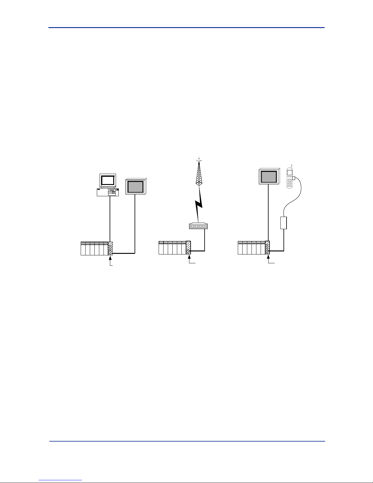
n Connection Diagram
PC
F3LC12-1F
Personal computer
link module
RS-232-C
cross cable
FA-M3
RS-232-C
cross cable
Modem
TA, etc.
RS-232-C
straight
cable
Public line
Dedicated line
F3LC11-1F
Personal computer
link module
RS-232-C
straight
cable
F3LC12-F
personal computer
link module
RS-232-C
cross cable
Display
with PC I/F
Mobile phone
adapter, etc.
Mobile
phone, etc.
FA10101.VSD
FA-M3
FA-M3
PC
Display
with PC I/F
Figure A1.1 Connection Diagram
Page 17
A1-3
IM 34M6H41-02E 2nd Edition : Aug. 1, 2005-00
A1.2 What can the Module Do?
n Personal Computer Link Function
The Personal Computer Link module is used to connect to high-level equipment such as
displays, personal computers, DUONUS
*1
, DCS*2, etc. When a FA-M3 PC link
command is transmitted from the high-level equipment, the Personal Computer Link
module returns a reply (response).
*1: Compact Field Server from Yokogawa Electric Corporation. It enables real-time monitoring of field data of the FA-M3
from a WWW browser or in an Internet environment, using the Webmetry field monitoring package.
*2 : Distributed Control System from Yokogawa Electric Corporation.
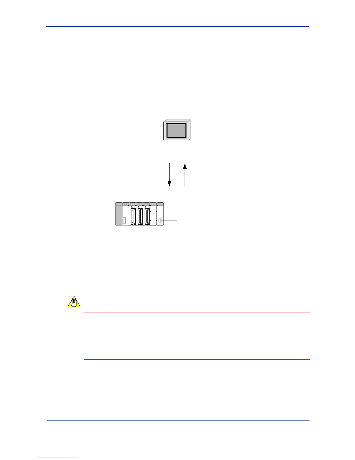
Command
"What's the
value of
D00001?"
Response
"It's $12EF."
FA10201.VSD
Higher-level
equipment
FA-M3
By exchanging commands and responses, all devices (D registers, I relays, current
values of timers/counters, etc.) of the FA-M3 CPU module can be read and written.
Moreover, personal computer link also enables uploading and downloading of ladder
programs, reading and setting of date and time, reading of error logs and alarms,
reading of user logs, etc. (For details, refer to the list of commands).
This communications is transparent to user programs on the FA-M3. (That is, no
communications program is required on the FA-M3).
CAUTION
PC link commands are issued according to the timing of the high-level equipment. To
transmit data to the high-level equipment according to the timing of the FA-M3, you can
either poll for data continuously from the high-level equipment, or alternatively, you can
write a program that uses the “Event Transmission Function” described later in this
subsection to transmit an event to the high-level equipment from the FA-M3, and have
the high-level equipment read the data once it receives this event.
Page 18

A1-4
IM 34M6H41-02E 2nd Edition : Aug. 1, 2005-00
n Event Transmission Function
You can send any data that is 30 words*1 or shorter from the FA-M3 to a higher-level
equipment. Event transmission requires some programming on the FA-M3 side. (You
can send an event by simply storing the data to be transmitted into the register of the
Personal Computer Link module and then turning on the Request to Send relay).
To send numeric data as ASCII character strings, simply turn on a 1-bit relay and the
module will automatically performs ASCII conversion and transmission.
Although PC link commands are processed according to the timing of the higher-level
equipment, the event transmission function allows data to be transmitted according to
the timing of the FA-M3.
CAUTION
Up to 30 words*1 (60 bytes) of data can be transmitted at each event transmission. To
transmit more than 30 words of data, write programs that use the event transmission
function to notify the higher-level equipment of a request to get data and when the highlevel equipment receives the event, it uses PC link commands to read data longer than
30 words.
*1 : On the F3LC12-1F, the limit is extended to 127 words.
n Modem Connection Function
By attaching a commercially-available external modem, you can do auto-dialing, redialing, send messages to beepers, etc. and use a password function to ensure security
on receiving, etc.
Besides modems using normal analog lines, you can also connect to the FA-M3 using
digital lines by connecting to a TA (terminal adapter) or even access the FA-M3 from a
place without telephone lines by connecting to a mobile phone adapter.
Page 19

A1-5
IM 34M6H41-02E 2nd Edition : Aug. 1, 2005-00
A1.3 Specifications of the PC Link Module
n Model Names and Specification Codes
Model
Name
Basic
Specification
Code
Styl e
Code
Specification
Code Suffix
Remarks
F3LC11 -1F …… …… 1 RS-232-C port
F3LC12 -1F …… …… 2 RS-232-C ports
n Operating Environment
F3LC11-1F, F3LC12-1F can be used with all CPU modules.
n Function Specifications
Item F3LC11-1F F3LC12-1F
Interface EIA RS-232-C compliant
Transmission
mode
Half-duplex transmission
Synchronization Start-stop synchronization
Transmission
speed
300/600/1200/2400/4800/9600/14400/19200/2
8800/38400/57.6k/76.8k/115.2Kbps
Transmission
distance
15m max.
Number of ports 1 port (non-insulated) 2 ports (non-insulated)
Start bit: 1
Data length: 7 / 8
Parity bit: None / even / odd
Data format
Stop bit: 1 / 2
Error detection Parity check, checksum
Control line
RS: Always on
ER: Always on
Xon/Xoff control None
Setup items
Transmission speed, data format, checksum,
ending character and protection
Protocol Proprietary protocol
Ending character Yes/No
Protection feature Yes/No
Access range
All sequence devices, BASIC common area,
upload/download ladder program, RUN/STOP,
read error history, read user log
Number of
modules
F3SP05, F3SP08, F3SP20, F3SP21: Max. 2
F3SP25, F3SP28, F3SP35, F3SP38, F3SP53,
F3SP58, F3SP59, F3BP20, F3BP30: Max. 6
* Total number including other similar function
modules (Ethernet interface module, GP-IB
communication module (slave))
Current
consumption
320mA 350mA
External connection D-sub 9-pin connector (female) mm-type M2.6
External
dimensions
28.9(W)×100(H)×83.2(D)mm
*1
Mass 110g
*1: Dimensions exclude protrusions (Refer to External Dimensions figure for details)
Page 20
A1-6
IM 34M6H41-02E 2nd Edition : Aug. 1, 2005-00
n Components and their Functions
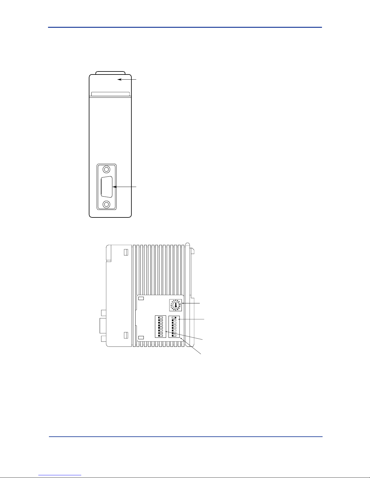
F3LC11-1F
Front View
RDY display:
Lit when the
internal circuit is
functioning
normally
RS-232-C connector:
D-sub 9-pin connector.
(mm-type M2.6 screws)
Connect to higher-level
computer, display, etc.
RDY
C LINK
LC11-1F
FA10301.VSD
Right Side View
Transmission speed switch:
Sets the transmission speed
of the module
Data format switch:
Defines the format of the
communication data
Rear
Front
This figure is drawn with the
panel cover removed.
Module function switch:
SW1
SW2SW3
Set this when connected to a
modem
1
2
3
4
5
6
7
8
O
F
F
1
2
3
4
5
6
7
8
O
F
F
FA10302.VSD
Page 21
A1-7
IM 34M6H41-02E 2nd Edition : Aug. 1, 2005-00
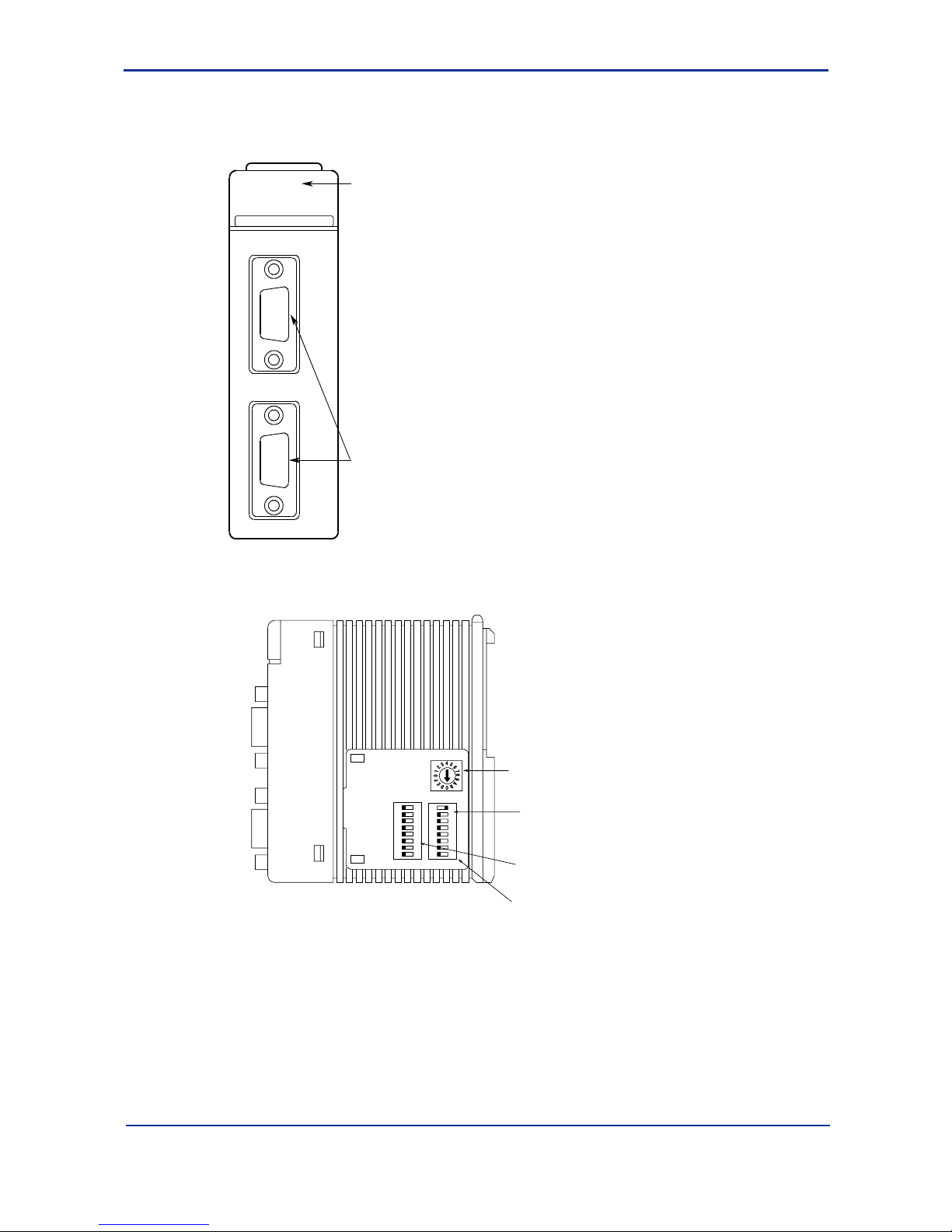
F3LC12-1F
Front View
RDY display:
Lit when the
internal circuit is
functioning
normally
RS-232-C connector:
D-sub 9-pin connector.
(mm-type M2.6 screws)
Connect to higher-level
computer, display, etc.
RDY
C LINK
LC12-1F
FA10303.VSD
1
2
Right Side View
Transmission speed switch:
Sets the transmission
speed of the module
Data format switch:
Defines the format of the
communication data
Rear
Front
This figure is drawn with the
panel cover removed.
Module function switch:
SW1
SW2SW3
Set this when connected
to a modem
1
2
3
4
5
6
7
8
O
F
F
1
2
3
4
5
6
7
8
O
F
F
FA10304.VSD
Page 22
A1-8
IM 34M6H41-02E 2nd Edition : Aug. 1, 2005-00
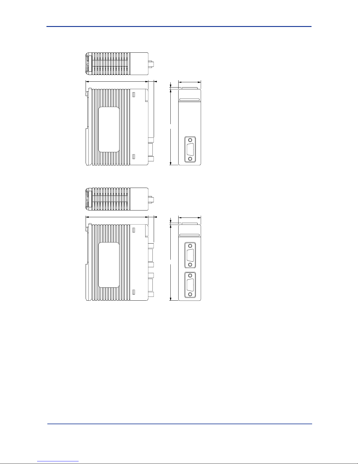
n External Dimensions
F3LC11-1F
83.2
28.9
2
FA10305.VSD
100
6.7
F3LC12-1F
83.2
28.9
2
FA10306.VSD
100
6.7
Page 23
A1-9
IM 34M6H41-02E 2nd Edition : Aug. 1, 2005-00
A1.4 Cables and Switch Setting
n Connecting Cables
There are two types of RS-232-C cables: cross cable (null modem cable) and straight
cable (modem cable).
Use a straight cable (normally provided with the modem) when connecting to a modem
and use a cross cable, otherwise.
If the cable connector is female, convert it to male using a gender changer, etc. The
connector of this module uses M2.6 mm screws. Take note that cables for personal
computers often uses inch screws instead.
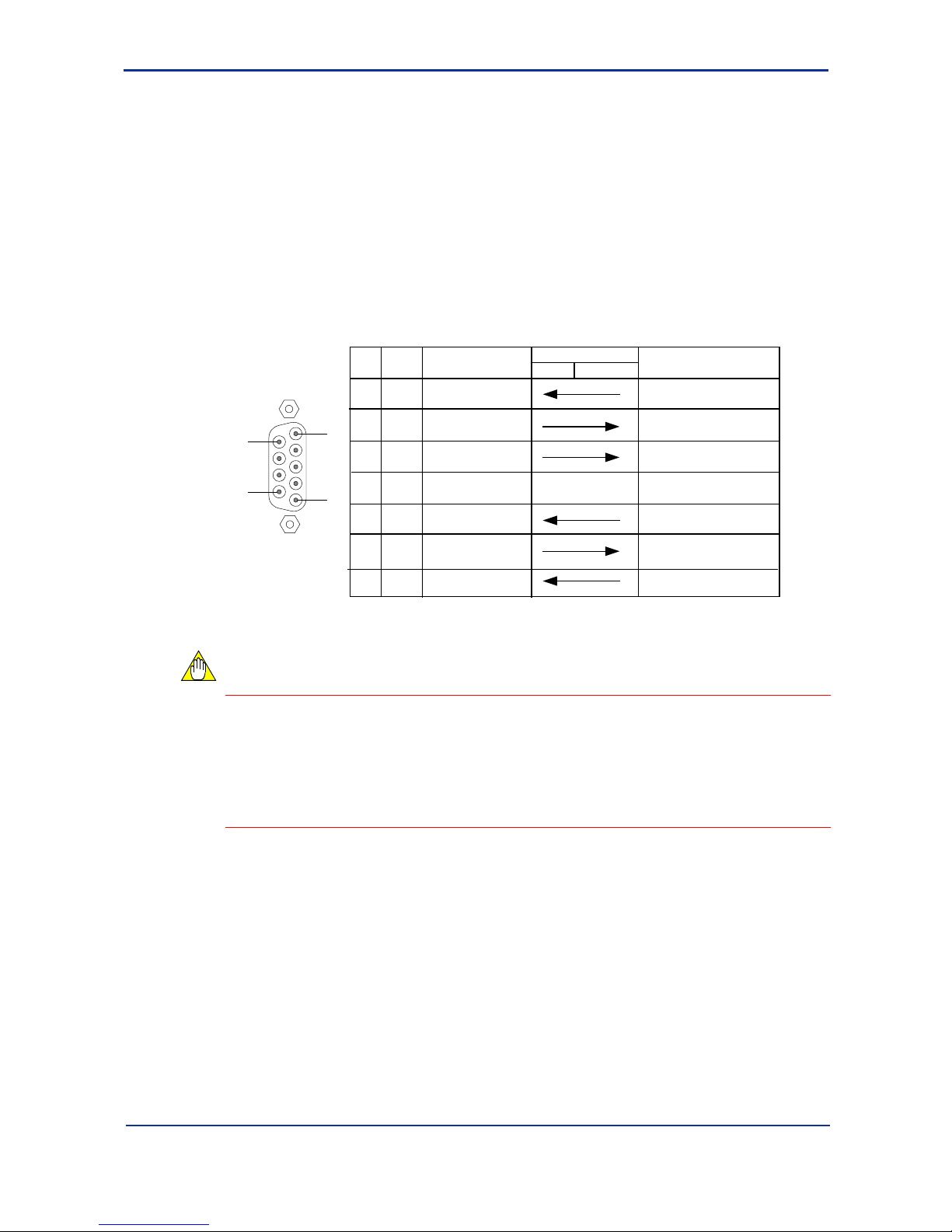
The connector specifications and cable interconnections are shown below.
Pin
no.
Signal
name
2RD
Receive Data
Data Terminal Ready
FA-M3
Higher-level
Always ON output in RDY st ate.
3
SD
4
ER
5
SG
6
DR
7
RS
8
CS
5
1
9
6
D-sub 9 pin (female)
Name
FA10401.VSD
Signal direction
Description
Send Data
Signal Ground
Data Set Ready
Request to Send
Clear to Send
Always ON input.
Always ON output in RDY st ate.
Always ON input.
Cannot send with OFF input
equipment
CAUTION
- The connector uses M2.6 mm screws. Take note that the cable for the personal
computer uses inch screws instead. If the cable connector is female, convert it to
male using a gender changer, etc.
- Transmission is not allowed if pin 8 does not turn on at the FA-M3
(F3LC11-1F/F3LC12-1F). When using a cross cable, use a cable with pin 7 and
pin 8 looped back.
Page 24
A1-10
IM 34M6H41-02E 2nd Edition : Aug. 1, 2005-00
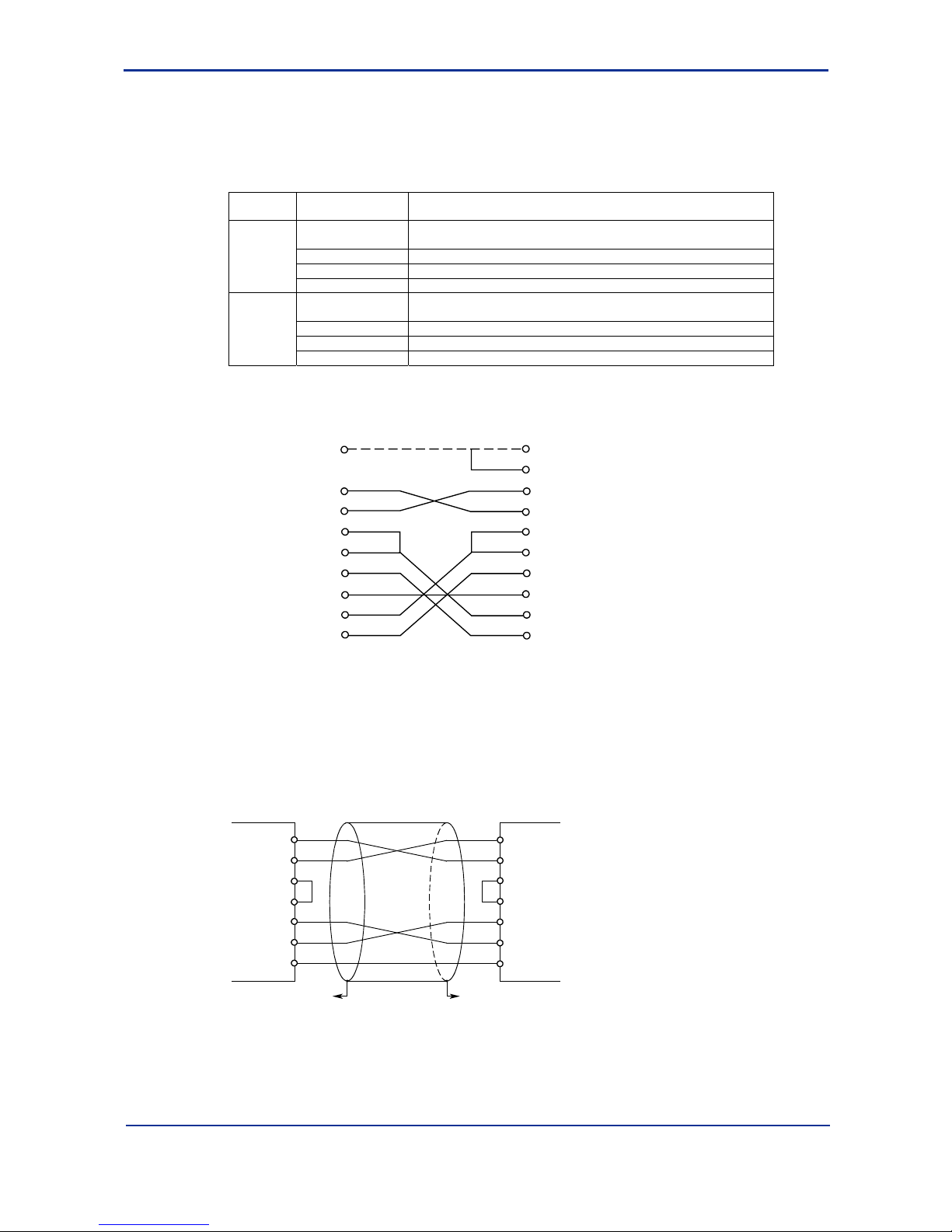
(1) Cabling Example for Connection to a Display
The connector on a display is D-sub 25-pin female.
Therefore, use a D-sub 25-pin male ↔ D-sub 9-pin male cross cable.
Null modem cables are available at the company. The modules and their specifications,
and internal connections are as follows:
Model
Basic
specification
Description
RS-232-C null modem cable with control line (9-25 pins)
ML gateway card (CP7□)-for connecting RS-232-C devices
-KM01 Cable length 1 m
-KM05 Cable length 5 m
YCB215
-KM15 Cable length 15 m
RS-232-C null modem cable without control line (9-25 pins)
ML gateway card (CP7□)-for connecting RS-232-C devices
-KM01 Cable length 1 m
-KM05 Cable length 5 m
YCB216
-KM15 Cable length 15 m
*: The pin number is dependent on the display. Refer to the display manual.
CN1 side (FA-M3)
PIN No.
Connector Cover
CN2 side
PIN No.
Connector Cover
Shield
3
2
7
8
6
5
1
4
1
2
3
4
5
6
7
8
20
FG
SD
RD
RS
CS
DR
SG
CD
ER
SD
RD
RS
CS
DR
SG
CD
ER
FA10402.VSD
(2) Cabling Example for Connection to a Personal Computer
The connector on a personal computer (DOS/V machine) is D-sub 9-pin male (inch
screw).
Therefore, use a D-sub 9-pin female (inch screw) ↔ D-sub 9-pin male (mm screw) cross
cable.
SD
Personal computer
link module
3
2
7
8
6
4
5
Connect to enclosure
of connector
Connect to enclosure
of connector
Personal computer
or display
3
2
7
8
6
4
5
D-sub 9-pin female
(M2.6 inch screw)
RD
RS
CS
DR
ER
SG
D-sub 9-pin male
(M2.6 mm screw)
SD
RD
RS
CS
DR
ER
SG
FA10403.VSD
When connecting to a personal computer with D-sub 25-pin connector, such as the old
PC-9801 series from NEC, use the same cables described in (1) Cabling Example for
Connection to a Display.
Page 25
A1-11
IM 34M6H41-02E 2nd Edition : Aug. 1, 2005-00
(3) Cabling Example for Connection to an External Modem
Connect using a straight cable. The connector on the modem is D-sub 9-pin.
Personal computer
link module
Connect to enclosure
of connector
Connect to enclosure
of connector
D-sub 9-pin male
(M2.6 mm screw)
Modem
FA10404.VSD
SD
3
SD
2
RD
RD
7
RS
RS
8
CS
CS
6
DR
DR
4
ER
ER
5
SG
SG
1
CD
CD
* When connecting to an external modem, always connect the CD signal.
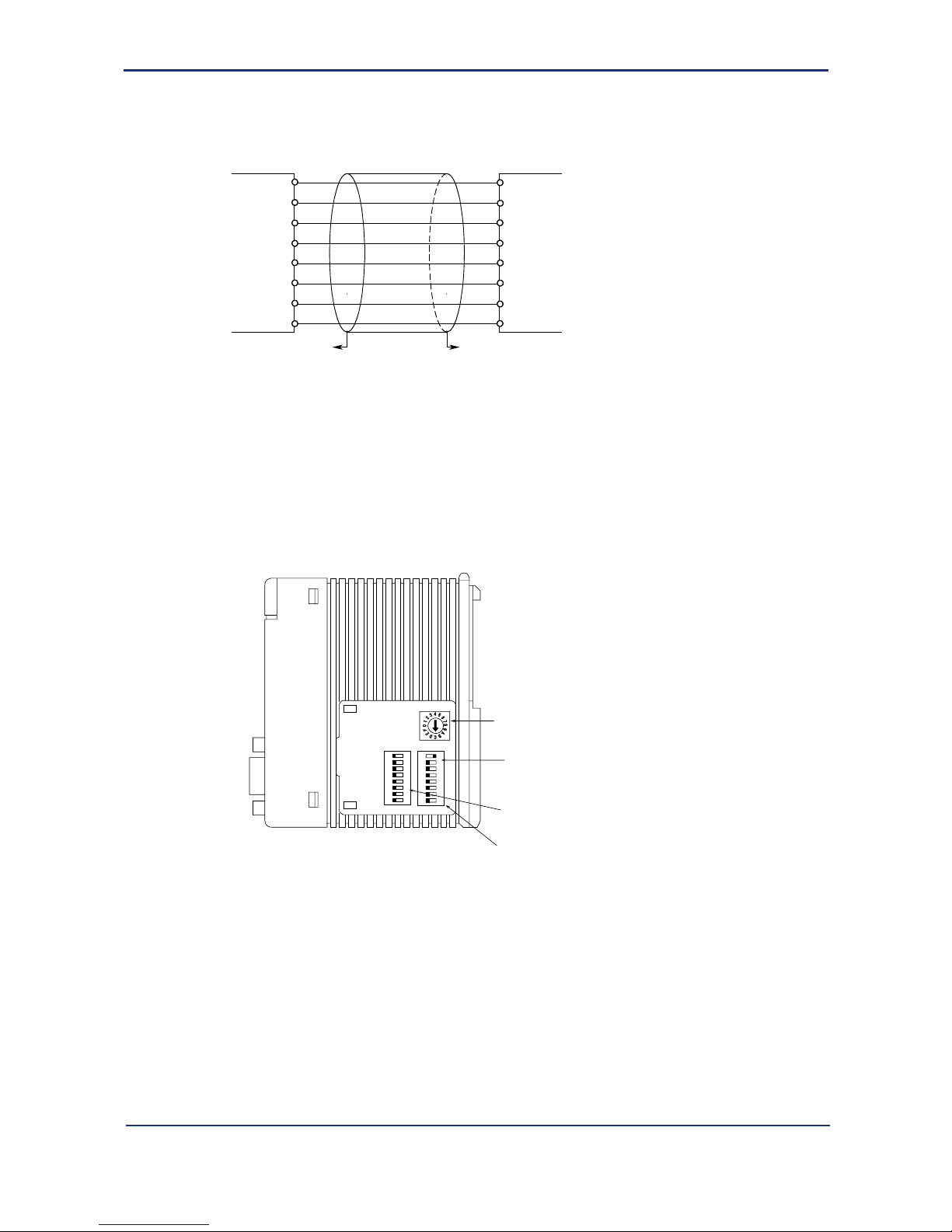
n Setting Module Switches
Figure A1.2 shows the name and location of module switches that must be set before
attaching the Personal Computer Link Module (F3LC11-1F/F3LC12-1F) to the FA-M3
Base Module.
Right Side View
SW1
SW2SW3
1
2
3
4
5
6
7
8
O
F
F
1
2
3
4
5
6
7
8
O
F
F
FA10405.VSD
Transmission speed switch:
Sets the transmission
speed of the module
Data format switch:
Defines the format of the
communication data
Rear
Front
This figure is drawn with the
panel cover removed.
Module function switch:
Set this when connected
to a modem
Figure A1.2 Locations of Switches on the Personal Computer Link Module
(F3LC11-1F/F3LC12-1F)
Page 26
A1-12
IM 34M6H41-02E 2nd Edition : Aug. 1, 2005-00
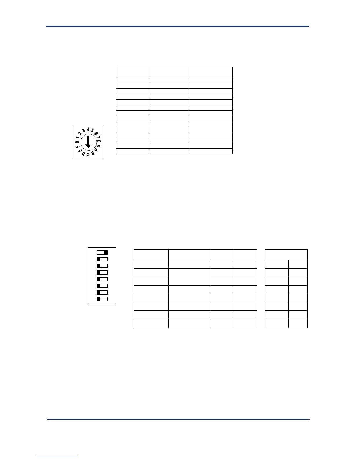
(1) Transmission Speed Switch (SW1)
Set the transmission speed using the hexadecimal rotary switch shown below. With an
appropriate ordinary screwdriver, change the direction of the arrow. Do not position the
arrow at D, E or F. The factory default setting of the switch is C (115.2 Kbps).
SW1 setting Transmission
speed (bps)
Remarks
0 300
1 600
2 1200
3 2400
4 4800
5 9600
6 14400 See note below
7 19200 See note below
8 28800
9 38400
A 57.6K
B 76.8K
C 115.2K Factory setting
D to F ------ Cannot be set
For F3LC12-1F, the switch setting applies to both port 1 and port 2.
Use software setup to change the setting for individual ports.
Note: On F3LC11-1N, switch setting 6 represents 19200 bps.
However, on F3LC11-1Fand F3LC12-1F, switch setting 7 represents 19200 bps.
(SW setting 6 represents 14400 bps)
Figure A1.3 Transmission Speed Switch of Personal Computer Link Module
(F3LC11-1F/F3LC12-1F)
(2) Data Format Switch (SW2)
Set the data transmission format using the 8-bit DIP switch. Set the DIP switch by
sliding each switch to the ON or OFF position. Up to six functions can be set with this
switch. The factory setting is ON for bit 1 and OFF for bits 2-8.
1
2
3
4
5
6
7
8
O
F
F
Number
(SW2)
Function OFF ON Factory setting
1 Character length 7 bits 8 bits 8 bits ON
2 None Yes None OFF
3
Parity
Odd Even ---- OFF
4 Stop bit 1 bit 2 bits 1 bit OFF
5 Checksum None Yes None OFF
6 Ending character None Yes None OFF
7 Protection feature None Yes None OFF
8 Security feature None Yes ---- OFF
- For F3LC12-1F, the SW setting applies to both port1 and port 2.
- To change the setting for an individual port, use software setting.
- SW2-3 is valid only if parity s enabled (SW2-2 is on).
- When connecting to a modem, use the following setting: “8 bits SW2-1=ON, No parity
SW2-2=OFF” or “7 bits SW2-1=OFF, with parity SW2-2=ON”
FA10407.VSD
Figure A1.4 Data Format Switch of Personal Computer Link Module (F3LC11-1F/F3LC12-1F)
Page 27
A1-13
IM 34M6H41-02E 2nd Edition : Aug. 1, 2005-00
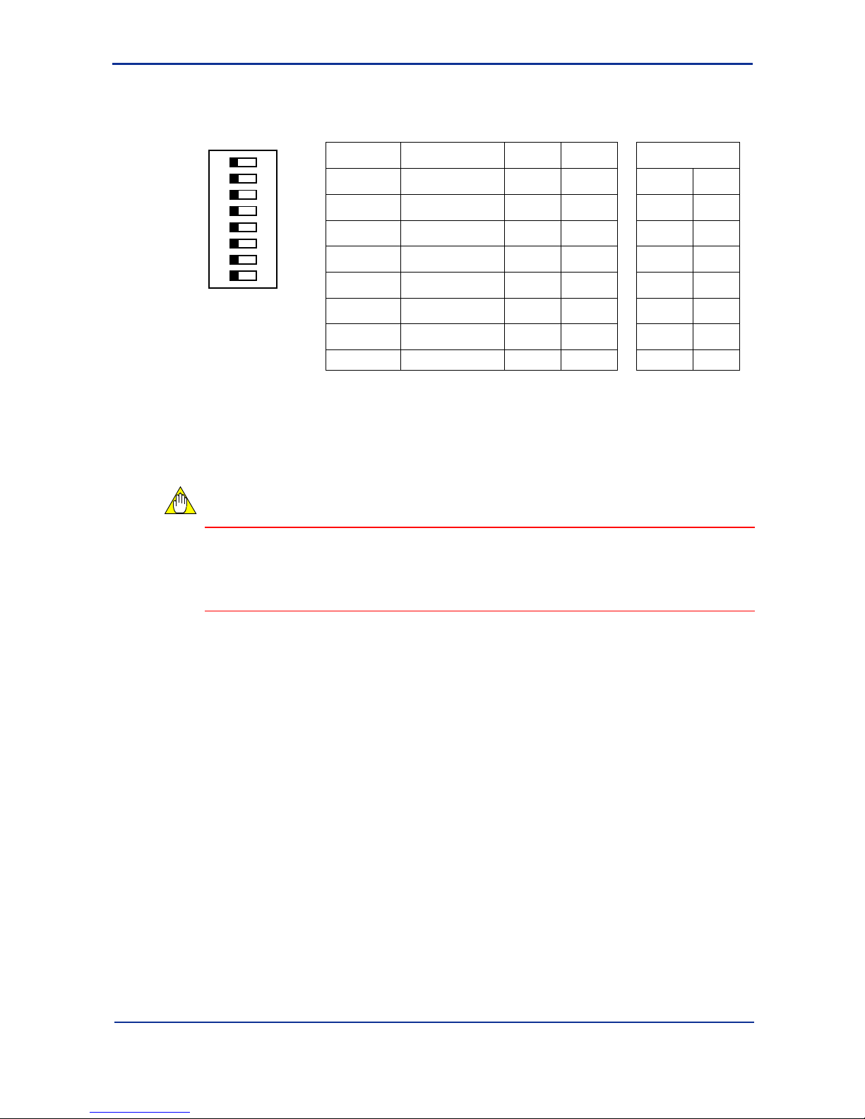
(3) Module Feature Switch
Use this switch to set the external modem support feature. The factory setting is all
OFF.
1
2
3
4
5
6
7
8
O
F
F
Number
(SW3)
Feature OFF ON Factory Setting
1
User setting not
allowed.
OFF
2
User setting not
allowed.
OFF
3
User setting not
allowed.
OFF
4
User setting not
allowed.
OFF
5
User setting not
allowed.
OFF
6
User setting not
allowed.
OFF
7
User setting not
allowed.
OFF
8 External Modem No Yes No OFF
- For F3LC12-1F, the SW setting applies to both port1 and port 2.
- To change the setting for an individual port, use software setting.
- SW3-1 to SW3-6 cannot be set by the user. Leave them OFF.
FA10408.VSD
Figure A1.5 Module Feature Switch of Personal Computer Link Module
(F3LC11-1F/F3LC12-1F)
CAUTION
Turn on SW3-8 when an external modem is connected. If a modem is not connected,
you must leave the bit off. If SW3-8 is on but no modem is connected or no power is
supplied to the modem, software setting of the communication parameters will be
delayed due to time out (about 65 seconds). (Setting will still be correctly done.)
Page 28
A1-14
IM 34M6H41-02E 2nd Edition : Aug. 1, 2005-00
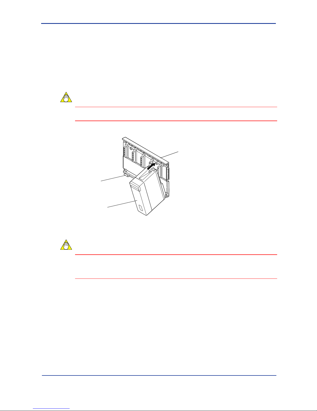
A1.5 Attaching and Detaching Modules
Attaching/Detaching Modules
Figure A1.6 shows how to attach this module to the base module. First, hook the anchor
slot at the bottom of the module to be attached onto the anchor pin on the bottom of the
base module. Push the top of this module towards the base module until the yellow
button clicks into place.
CAUTION
Always switch off the power before attaching or detaching a module.
Base module
This module
Anchor pin
FA10501.VSD
Figure A1.6 Attaching or Detaching this module
CAUTION
Do not bend the connector on the rear of the module by force during the above
operation. If the module is pushed with improper force, the connector may bend causing
an error.
Detaching Modules
To remove this module from the base module, reverse the above operation.
Press the yellow button on the top of this module to unlock it, and titling the module
away from the base module. Then lift the module off the anchor pin at the base.
Page 29
A1-15
IM 34M6H41-02E 2nd Edition : Aug. 1, 2005-00
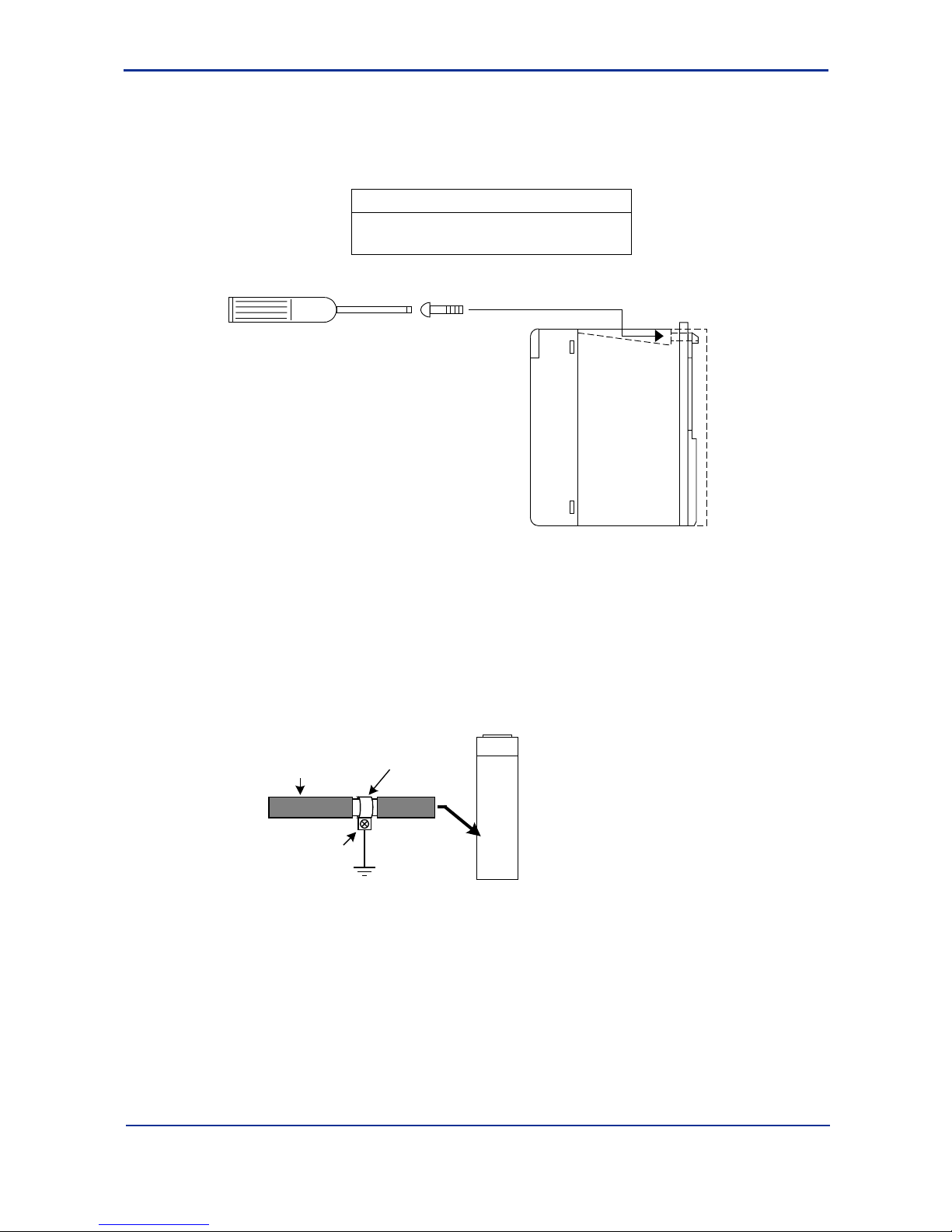
n Attaching Modules in Intense Vibration Environments
If the module is used in intense vibration environments, fasten the module with a screw.
Use a screw described in the table below and tighten it into the guide channel at the top
of this module with a phillips screwdriver.
Screw to be provided
Binder screw M4, length 12-15mm
(For screw with washer, the length should be
14-15mm)
FA10502.VSD
Figure A1.7 Fastening this Module with a Screw
n Grounding of Cable
To ensure compliance to CE Marking for a system incorporating this module, use a
shielded cable for connecting to the module. Peel off part of the insulation of the shielded
cable to expose the shield, and apply an FG clamp to the shield to secure and ground it
Peel of f ins ulation and
apply an FG clamp to
the exposed shield.
Shielded cable
Screw the FG clamp
to the metal plate of
the panel enclosure
for grounding.
Page 30

A1-16
IM 34M6H41-02E 2nd Edition : Aug. 1, 2005-00
A1.6 Connecting to a Display
To connect to a display, use the following procedure.
1. Draw the screen data on the PC.
2. Transmit the screen data to the display.
3. Match the communication conditions on the display and this module.
4. Connect this module to the display and start monitoring.
n Items Required for Connecting to a Display
(1) Display (TOP77RT from Digital is shown here as an example).
(2) PC with display drawing tool (GP-PRO/PB3 for Windows)
(3) Display↔module connection cable
(4) GP screen transmission cable
n Create Screen Data
Create a new project.
FA10601.VSD
Yokogawa Electric Corporation FACT
GP577R
TOPsample
Select GP type=GP577R, PLC type=Yokogawa Electric Corporation FACTORY ACE 1:1 Communication.
Page 31

A1-17
IM 34M6H41-02E 2nd Edition : Aug. 1, 2005-00
Create the following screen on the following screen. There are 3 components.
(1) Numeric display Word address = 1D0001
(2) Bit switch 1 Operating bit address = 1I0001
Check-mark the State Change item
Monitor bit address = 1I0001
Bit operation = Set
Change Fg color when state is ON to white
Change Fg color when state is OFF to green
(3) Bit switch 2 Operating bit address = 1I0001
Check-mark the Status Change item
Monitor bit address = 1I0001
Bit operation = Reset
Change Fg color when state is OFF to white
Component for
value display
Bit Switch 1
Bit Switch 2
FA10602.VSD
The ‘1’ preceding the device name is the CPU number. When the FA-M3 is used with
multiple CPUs, you can access devices of the required CPU by entering 2, 3 or 4 in this
position.
Page 32

A1-18
IM 34M6H41-02E 2nd Edition : Aug. 1, 2005-00
n Transfer Screen Data
After saving the screen data and the project, transfer the screen data to the display.
Before transferring the screen data, check that the display is connected to the PC with a
dedicated transfer cable.
n Set Communication Parameters
Set the module switches as follows:
SW1: C (115.2Kbps)
SW2: turn on 1 and 6 and turn off the rest (8 bits, Ending character “Yes”)
SW3: turn everything off
n Set Communication Parameters on the Display side
Set the communication parameters of the display (TOP) as follows:
1. Turn on the power to the TOP and press on the three corners of the screen for a
short while. (Press on three points)
Depending on the previous communication parameters, this may take a while.
2. Click [Off-line] at the bottom of the screen to enter off-line mode.
3. On the main menu, touch 1 Initialization → 2 Setup I/O → 1 Setup
Communication. On the communication setting screen, set the values as shown
below and touch Exit.
8
1
None
ER control
RS232C
115200
Communication Setting
Transmission
speed
Data Length
Stop bits
Parity
Flow control
Communication
mode
2400 4800 9600 19200 38400 57600
7
2
Odd Even
X control
Cancel
Exit
FA10603.VSD
4-line 2-line
Page 33

A1-19
IM 34M6H41-02E 2nd Edition : Aug. 1, 2005-00
4. This returns you to the Initialization menu. Select 3 Setup Operating
Environment.
The following screen opens. (This screen is not described in the GP-PRO user
manual.) Touch 1:1 here, followed by 1 Setup Operating Environment.
1:1
Operating Environment Menu
n:1
Setup operating environment
Previous
1
FA10604.VSD
5. Enter ‘1’ for the Equipment no. and set the System Area to ‘1D1001’.
(However, if the system area is set to ‘Do not use’ on the System Environment
setting screen, the value ‘1D0001’ will be acceptable.
Setup Operating Environment
System area start address
Equipment no.
System area, read area size (0-256)
GP reset on write error
[ 1D1001 ]
[ 1 ]
[ 0 ]
Yes No
CancelExit
FA10605.VSD
CAUTION
- Note that the default machine number is 0 but communication is not allowed if this
value is left unchanged.
- You should specify an area that is not used in the ladder (user program) for the
system area.
Page 34

A1-20
IM 34M6H41-02E 2nd Edition : Aug. 1, 2005-00
6. Touching Exit returns you to the main menu. Touch 4 Operate and
communication starts.
If the following ladder program is downloaded in advance, then you can start
count-up to the numerical value using
and stop the count-up using .
Program on the FA-M3 side.
FA10606.VSD
0001
I00001 M00039
D00001 D00001
1
=+
If I00001 is turned on, D0001 increments on the rising edge of the M00039 clock.
Turning off I00001 stops the count-up.
CAUTION
If count-up is not performed, check that the system area is not 1D0001.
Page 35

A1-21
IM 34M6H41-02E 2nd Edition : Aug. 1, 2005-00
A1.7 Connecting to a PC
n Sample Program on the PC Side
Here, we use Visual Basic (hereinafter known as VB) to create a sample program on the
PC side that monitors the status of devices on the FA-M3 side.
Leave the default values (115.2Kbps, 8 bit, no parity) of the switches on the side of the
F3LC11-1F/F3LC12-1F unchanged. You can insert the module into any slot.
Use VB Professional Edition or higher. (Comm control is not available in the Learning
Edition).
1. Add the Microsoft Comm control to VB.
Select [Project]→[Component] from the menu bar.
Page 36

A1-22
IM 34M6H41-02E 2nd Edition : Aug. 1, 2005-00
Select [Microsoft Comm Control] and click [OK].
Verify that the telephone control is added.
Check that the telephone icon
has been added
Page 37

A1-23
IM 34M6H41-02E 2nd Edition : Aug. 1, 2005-00
2. Create a form
Paste the Comm control added in step 1 (at any position), a label, a text box, an
option button and 2 command buttons on the form and define the caption for each
control.
Text box
Label
Option button
Comm control
Command button 2 Command button 1
FA10704.VSD
This sample program reads the values of D0001 and M0040 when the Start button is
clicked.
3. Enter the source code.
(General) (Declarations)
Dim start_flg As Integer
(General) Do_Send
Private Sub Do_Send( )
Dim sendtext1 As String, sendtext2 As String
Dim recvtext1 As String, recvtext2 As String
sendtext1 = Chr(2) + "01010WRDD0001,01" + Chr(3) 'D0001 read command
sendtext2 = Chr(2) + "01010BRDM0040,001" + Chr(3) 'M0040 read command
'========================= D0001 word read command send
MSComm1.InBufferCount = 0
MSComm1.Output = sendtext1 'WRD command send
recvtext1 = ""
Do
DoEvents
dmy = DoEvents( )
If MSComm1.InBufferCount Then
recvtext1 = recvtext1 + MSComm1.Input
If InStr(recvtext1, Chr(3)) Then
Text1.Text = Mid(recvtext1, 8, 4) ' 0101OK1234
Exit Do
End If
End If
If start_flg = 0 Then Exit Do
Loop
Page 38

A1-24
IM 34M6H41-02E 2nd Edition : Aug. 1, 2005-00
'========================= M0040 bit read command send
MSComm1.InBufferCount = 0
MSComm1.Output = sendtext2 'BRD command send
recvtext2 = ""
Do
DoEvents
dmy = DoEvents( )
If MSComm1.InBufferCount Then
recvtext2 = recvtext2 + MSComm1.Input
If InStr(recvtext2, Chr(3)) Then
temp = Mid(recvtext2, 8, 1) ' str+0101OK1
If temp = "1" Then
Option1.Value = True ' ON
Else
Option1.Value = False ' OFF
End If
Exit Do
End If
End If
If start_flg = 0 Then Exit Do
Loop
End Sub
Command1 Click
Private Sub Command1_Click( )
'========================= "Exit"
start_flg = 0
MSComm1.PortOpen = False 'PC com port close
End Sub
Command2 Click
Private Sub Command2_Click( )
'========================= "Start"
start_flg = 1 'PC link command start
'========================= PC com port set
MSComm1.CommPort = 1 'PC com port
MSComm1.Settings = "115200,N,8,1" '115.2Kbps, Non parity, 8 bits
'========================= port open
On Error Resume Next
MSComm1.PortOpen = True 'PC com port open
If Err.Number <> 0 Then
MsgBox "COM port open error", , "Error"
Exit Sub
End If
Do
DoEvents
If start_flg = 1 Then Do_Send
Loop
End Sub
Page 39

A1-25
IM 34M6H41-02E 2nd Edition : Aug. 1, 2005-00
Form Load
Private Sub Form_Load( )
start_flg = 0
End Sub
Form Unload
Private Sub Form_Unload(Cancel As Integer)
End
End Sub
4. Execution Result
When you click the Start button, the value of D0001 is displayed in hexadecimal
format (0000-FFFF) and the option field beside M0040 blinks at 1-second interval.
To stop the communication, click the Exit button.
FA10705.VSD
Creating the following ladder program increments the value of D0001 every 0.2 seconds.
FA10706.VSD
0001
M00039
D00001 D00001
1
=+
Page 40

A1-26
IM 34M6H41-02E 2nd Edition : Aug. 1, 2005-00
A1.8 Connecting to a Modem
n Setting and Sample Program when Connecting to a Modem
We describe here how to connect to an external modem and send a message to a
beeper. Sending a message to a beeper requires programming in ladder or BASIC.
The program writes the telephone number of the beeper and the message to be
transmitted to the internal registers of this module, turns on the Dial Request relay to
start auto-dialing. Once connected, it turns on the Request to Send output relay (internal
dummy relay of this module) to start transmission.
1. Set the switches
Turn on (“Yes”) bit 8 of SW3 (External Modem: Yes/No) .
Set the other switches to default.
2. Connect to the modem using a straight cable.
If the cable provided with the modem is female and does not match, use a gender
changer.
3. A sample ladder program is shown below.
Transmit 0 for external transmission. The beeper number is 1234-5678-9999.
The send message is “LC11-1F” in the sample program.
If I1001 is turned on, the program dials the beeper and sends a message.
FA10801.VSD
WRITE $3936 2 107 1
WRITE $3936 2 106 1
WRITE $3138 2 105 1
WRITE $3337 2 104 1
WRITE $2A32 2 103 1
WRITE $2A32 2 102 1
WRITE 12 2 29 1
WRITE 1 2 30 1
0015
0014
0013
0012
0011
0010
M00035
0009
0008
0007
0006
0004
0003
0002
0001
M00035
Transmission message ("LC11-1F") Transmission data area=101-111
Setting beeper telephone number (0-1234-5678-9999)
Telephone number area=31-34
Number of digits for telephone number (12) and
number of digits for external line transmission (1)
96"1"
96"1"
18"C"
37"L"
*2
*2 free words
WRITE $4567 2 32 1
WRITE $8999 2 33 1
WRITE $9000 2 34 1
0005
M00035
WRITE $123 2 31 1
M00035
WRITE 18 2 101 1
0016
Transmission data
size
Page 41

A1-27
IM 34M6H41-02E 2nd Edition : Aug. 1, 2005-00
FA10802.VSD
0030
0029
0028
0027
0026
0025
X00205
0024
0023
0022
0021
0020
0019
0018
0017
M00035
Beeper Transmit Flag (YImm39)
0035
0034
0033
0032
0031
26"F"
96"1"
69"-"
I01 001
Dial Request (YImm40)
I01 001
X00206
X00208
Request to Transmit Message (YImm34)
Request to Disconnect Line (YImm43)
SET Y00234
X00205
X00202
X00202
I001 01
X00209
T00001
I001 01
T00001
X00205
X00208
SET Y00239
SET Y00240
RST Y00240
RST Y00234
T00001
0.0ms
TIM
4s
SET Y00243
RST Y00243
WRITE $3639 2 108 1
WRITE $3936 2 109 1
WRITE $3236 2 110 1
* Message transmission to beepers is not available in some countries and regions.
Page 42

A1-28
IM 34M6H41-02E 2nd Edition : Aug. 1, 2005-00
n Relay Sequence during Message Transmission
FA10803.VSD
I01001
T0001
Y00234
Y00243
Y00241
Y00240
Y00239
X00202
X00209
X00208
X00207
X00206
X00205
Dial Request
source occurs
Timeout
Start Timer
Request
to Transmit
Transmit to beeper (al ways on)
Dial Request
Tone line (always off )
Disconnect
Line
Transmi ssion
Completed
Connected
Relay Sequence of the Message Transmission Function
Page 43

A1-29
IM 34M6H41-02E 2nd Edition : Aug. 1, 2005-00
A1.9 Software Specifications of the PC Link Module
This module has internal input/output relays and registers. These are used to store
setting values when setting the communications parameters using software, the dialing
number during auto-dialing, the transmission data during event transmission as well as
to issue dial requests and send requests.
(They are not used in the PC link functions).
Input/Output Relays
Output relays: Turn on these relays to dial a request to this module from the FA-M3
(33-64) CPU module, etc. When processing of the request is completed
and the completion relay turns on, turn off the request relay.
Input relays: When processing of the request is completed, the module turns on
(01-32) an input relay. Turning off the request relay also turns off the
completion relay.
These relays are also used to show the line connection status, etc.
Table A1.2 List of Output Relays
Relays Used
for different
functions
Output
Relay
Name Description
E M S
Ylmm33 Reserved ― ― ―
Ylmm34 #1
Ylmm50 #2
Request to Send
Turn on this relay to request for event or message transmission.
Turn it off after the Transmission Completed relay turns on.
―
Ylmm35 #1
Ylmm51 #2 Setup Request
Turn on this relay to request for software setting of the data format or
transmission speed.
Turn it off after the Setup Completed relay turns on.
― ―
Ylmm36 Reserved ― ― ―
Ylmm37 #1
Ylmm53 #2
Header/Footer
Turn on this relay to attach a header or a footer before event transmission.
(ON: attach header/footer, OFF: no header/footer)
―
―
Ylmm38 #1
Ylmm54 #2
ASCII Conversion
Turn on this relay to perform ASCII conversion before event transmission.
(ON: perform ASCII conversion, OFF: do not perform ASCII conversion)
―
―
Ylmm39 #1
Ylmm55 #2
Transmit Message
to Beeper
Turn on this relay before a dial request when transmitting a message to a
beeper. (Turn it off for normal dialing.)
―
―
Ylmm40 #1
Ylmm56 #2
Dial Request
Turn on this relay to request for dialing. Turn it off if the Connected relay,
the Connection Failed relay, or the Disconnection Failed relay is on.
―
―
Ylmm41 #1
Ylmm57 #2
Line Type
Turn this relay on or off before a dial request to match the line in use.
(ON: pulse, OFF: tone)
―
―
Ylmm42 #1
Ylmm58 #2
Redial
Turn on this relay before a dial request if redialing is required.
(ON: redial, OFF: do not redial)
―
*1
―
Ylmm43 #1
Ylmm59 #2
Disconnect Line
Turn on this relay to request for a line disconnection.
Turn it off if the Connected relay is off or if the Disconnection Failed relay
is on.
―
―
In “Ylmmnn”, “l” denotes the unit, and “mm” denotes a slot
F3LC12-1F: #1: for port 1/ #2: for port 2
F3LC11-1F: use only #1. #2 is reserved.
*1: Redialing is not allowed for message transmission to beeper.
Relays not listed in the above table are reserved by the system.
Do not use reserved relays.
E: Event Transmission Function
M: Modem Connection Function
(dialing, message transmission)
S: Software setting function
Page 44

A1-30
IM 34M6H41-02E 2nd Edition : Aug. 1, 2005-00
Table A1.3 List of Input Relays
Relays Used
for Different
Functions
Input Relay Name Description
E M S
Xlmm01 Reserved ― ― ―
Xlmm02 #1
Xlmm18 #2
Transmit
Completed
When Request to Send is turned on, Transmit Completed turns on when
transmission is completed.
Turning off Request to Send also turns off Transmit Completed
―
Xlmm03 #1
Xlmm19 #2
Setup
Completed
When Setup Request is turned on, Setup Completed turns on when setup is
completed.
Turning off Setup Request also turns off Setup Completed
― ―
Xlmm04 Reserved ― ― ―
Xlmm05 #1
Xlmm21 #2 Connected
When Dial Request is turned on, Connected turns on when line connection is
completed.
Turning on Disconnect Line also turns off Connected.
―
―
Xlmm06 #1
Xlmm22 #2
Connection
Failed
When Dial Request is turned on, Connection Failed turns on when connection
fails.
Turning off Dial Request also turns off Connection Failed.
―
―
Xlmm07 #1
Xlmm23 #2 Redialing
Turns on during redialing. Redialing turns off when any of the following
happens: Connected turns on, Connection Failed turns on, or Dial Request
turns off.
―
―
Xlmm08 #1
Xlmm24 #2
Disconnection
Failed
When Disconnect Line is turned on, Disconnection Failed turns on when
disconnection fails.
Turning off Dial Request or Disconnect Line also turns off Disconnection Failed.
―
―
Xlmm09 #1
Xlmm25 #2
Connected
from External
Turns on when connected to an external line.
Turns off when the line is disconnected.
―
―
In “Xlmmnn”, “l” denotes the unit, and “mm” denotes a slot
F3LC12-1F: #1: for port 1/ #2: for port 2
F3LC11-1F: uses only #1. #2 is reserved.
Relays not listed in the above table are reserved for future use.
Do not use reserved relays.
Module Internal Register
The Personal Computer Link Module has two types of internal registers.
(1) Mode registers: store communications parameters, dial numbers, and other settings.
(2) Output data registers: store events, messages and other transmission data.
Table A1.4 List of Mode Registers
CPU Access
using Ladder
CPU Access
using Basic
RegistersUsed
by Individual
Functions
Data Position
Number
Data Position
Number
Name Setting Range
Default
Value
E M S
27 #1
77 #2
27 #1
77 #2
Redial Interval 70~999 (ms) 70 – –
28 #1
78 #2
28 #1
78 #2
Redial Limit 1-10 1 – –
29 #1
79 #2
29 #1
79 #2
Telephone Number Size 1-20 10 – –
30 #1
80 #2
30 #1
80 #2
Number of Dial Digits for
External Line Connection
0-10 0 – –
31 to 35 #1
81 to 85 #2
31 to 35 #1
81 to 85 #2
Telephone Number
$0000 to $9999
(BCD 4 digits*5)
$0000 – –
36 #1
86 #2
36 #1
86 #2
Security Password
$0000 to $9999
(BCD 4 digits)
$0000 – –
37 #1
87 #2
37 #1
87 #2
Station Number Setting Always 1 1 – –
38 #1
88 #2
38 #1
88 #2
Data Format Setting $00 to $FF $01 – –
39 #1
89 #2
39 #1
89 #2
Transmission Speed Setting $0 to $C $C – –
40 #1
90 #2
40 #1
90 #2
Beeper Connection Time 10 to 60 (s) 30 – –
45 #1
95 #2
45 #1
95 #2
CPU Number in Header
during Event Transmission
1 to 4 1 –
49 #1
99 #2
49 #1
99 #2
Modem Receiving Interval 0 to 999 (ms) 8 – –
E: Event Transmission Function
M: Modem Connection Function
(dialing, message transmission)
S: Software setting function
Page 45

A1-31
IM 34M6H41-02E 2nd Edition : Aug. 1, 2005-00
Table A1.5 List of Output Data Registers
CPU Access
Using Ladder
CPU Access
Using Basic
Registers Used
for Individual
Functions
Data Position
Number
Data Position
Number
Name Setting Range
Default
Value
E M S
101-131 #1
101-228 #1
401-528 #2
1-31 #1
1-128 #1
301-428 #2
Events, messages, and
other transmission
data
*1
F3LC11-1F: 31 words
(101 to 131 (1 to 31))
F3LC12-1F: 128 words
(Port 1: 101 to 228 (1
to 128)
(Port 2: 401 to 528 (301
428))
Data position numbers
in brackets are for
BASIC CPU access.
None –
*1: For F3LC11-1F, the data size for event or message transmission is 30 words max.
For F3LC12-1F, the data size is 127 words max. for each port.
Accessing from BASIC
Using the PC Link Module with the personal computer link function to access the
common area of a BASIC CPU module does not require creation of a program on the
BASIC CPU. The BASIC common area can be directly accessed as D registers and I
relays. For details, see the description on the device access commands for BASIC
CPUs in Section 1.3 of the Personal Computer Link Command Instruction Manual
(IM34M6P41-01E).
When using the PC Link Module for event reporting or message transmission to a
beeper, or when performing software setting of the module, access it as follows:
(1) Declaring the use of the module.
Before you use the module, you must declare its use using the ASSIGN statement.
Always execute the ASSIGN statement before accessing the module (using
ENTER/OUTPUT/STATUS/CONTROL statements).
ASSIGN LC11 = SL (for F3LC11-1F)
ASSIGN LC12 = SL (for F3LC12-1F)
SL: Slot number (numeric value, or numeric variable)
Page 46

A1-32
IM 34M6H41-02E 2nd Edition : Aug. 1, 2005-00
(2) Accessing X and Y relays
Access the input (X) and output (Y) relays of the module in units of 16 points (1
word).
- Reading from input relays
To read from input relays, use the STATUS statement.
STATUS SL, n; P
SL : Slot number
n : Data position number (101: Xlmm01 to Xlmm16; 102: Xlmm17 to Xlmm32)
P : Variable for storing read data
- Writing to output relays
To write to output relays, use the CONTROL statement.
CONTROL SL, n; P, M
SL : Slot number
n : Data position number (101: Xlmm33 to Xlmm48; 102: Xlmm49 to
Xlmm64)
P : Output data
M : Mask pattern
Xlmm01
Xlmm02
Xlmm03
Xlmm16
Data
position
number
101
Xlmm17
Xlmm18
Xlmm19
Xlmm32
Data
position
number
102
15 14 13 12 11 10 9 8 7 6 5 4 3 2 1 0
15 14 13 12 11 10 9 8 7 6 5 4 3 2 1 0
:
:
Ylmm33
Ylmm34
Ylmm35
Ylmm48
Data
position
number
101
Ylmm49
Ylmm50
Ylmm51
Ylmm64
Data
position
number
102
15 14 13 12 11 10 9 8 7 6 5 4 3 2 1 0
15 14 13 12 11 10 9 8 7 6 5 4 3 2 1 0
:
:
Page 47

A1-33
IM 34M6H41-02E 2nd Edition : Aug. 1, 2005-00
To change specific bits of output data, use a mask pattern. Data bits corresponding
to 1s in the mask pattern will change, but those corresponding to 0s will not.
Example:
Output data P = $0640 0 0 0 0 0 1 1 0 0 1 0 0 0 0 0 0
Mask pattern M = $0750 0 0 0 0 0 1 1 1 0 1 0 1 0 0 0 0
↓
Output relay before execution $3B36 0 0 1 1 1 0 1 1 0 0 1 1 0 1 1 0
Output result $3E66 0 0 1 1 1 1 1 0 0 1 1 0 0 1 1 0
(3) Accessing mode registers
- Reading from mode registers
To read from mode registers, use the STATUS statement.
STATUS SL, n ; I
SL : Slot number
n : Data position number
I : Integer-type variable or integer-type array variable for storing read
data
- Writing to mode registers
To write to mode registers, use the CONTROL statement.
CONTROL SL, n; I
SL : Slot number
n : Data position number
I : Constant, or integer-type variable or integer-type array variable storing
data to be written.
(4) Accessing output data registers
- Writing to output data registers
To write to output data registers, use the OUTPUT statement.
OUTPUT SL, n, NOFORMAT; I
SL: Slot number
n : Data position number
I : Constant, or integer-type variable or integer-type array variable storing
data to be written.
Page 48

Blank Page
Page 49

A2-1
IM 34M6H41-02E 2nd Edition : Aug. 1, 2005-00
A2. PC Link Function
You can read from or write to all devices of the FA-M3 and upload/download programs
from a display, a personal computer or other equipment that supports Yokogawa’s PC
link commands. Moreover, you can also read different types of information (CPU
operating status, I/O configuration, cause of errors and alarms, etc.), read and write date
and time data, and read user logs.
There is no need to create any user communications program on the CPU module of the
FA-M3 to use the PC link functions.
Page 50

A2-2
IM 34M6H41-02E 2nd Edition : Aug. 1, 2005-00
n List of Commands
A list of commands that can be used on the PC link module is given below. For details,
refer to “Personal Computer Link Command” Manual (IM34M6P41-01E).
Table A2.1 Device Bit Access Commands
Command
ASCII
Function
Number of Points Handled per
Communication
"BRD" Reads bits. 1-256 bits
"BWR" Writes bits. 1-256 bits
"BFL" Writes bits of the same data 1-256 bits
"BRR" Reads bits randomly. 1-32 bits
"BRW" Writes bits randomly. 1-32 bits
"BRS" Specifies the devices to be monitored in bit unit. 1-32 bits
"BRM" Monitors bits. 1-32 bits
Table A2.2 Device Word Access Commands
Command
ASCII
Function
Number of Points Handled per
Communication
"WRD" Reads words. 1-64 words
"WWR" Writes words. 1-64 words
"WFL" Writes words of the same data 1-256 words
"WRR" Reads words randomly. 1-32 words
"WRW" Writes words randomly. 1-32 words
"WRS" Specifies the devices to be monitored in word unit. 1-32 words
"WRM" Monitors words. 1-32 words
Table A2.3 Special Module Access Commands
Command
ASCII
Function
Number of Points Handled per
Communication
"SWR" Reads words. 1-64 channels (words)
"SWW" Writes words. 1-64 channels (words)
"SLR" Reads long words. 1-32 channels (words)
"SLW" Writes long words. 1-32 channels (words)
Special modules refer to analog input/output modules, advanced positioning modules, GP-IB communications modules, etc.
Table A2.4 Sequence Program Access Commands
Command
ASCII
Function
"PRI" Reads program information.
"PLC" Cancels program loading or saving.
"PLD" Loads a program.
"PSV" Saves a program.
"STA" Starts a program.
"STP" Stops a program.
"PLX" Loads a program (for 1024 blocks)
*1
"PSX" Saves a program (for 1024 blocks)*1
These commands are used for sequence CPUs. It is not supported for BASIC CPUs.
*1: Load/Save commands for 1024 blocks are only supported by this module.
Programming ports of F3LC11-N, F3LE01-5T, CPU modules are not supported (as of 31st January 2001).
Table A2.5 Test Commands
Command
ASCII
Function
"TST" Performs a (loopback) test.
Table A2.6 Miscellaneous Commands
Command
ASCII
Function
"MDR" Resets the module.
"INF"
Reads information (CPU operating status, I/O configuration,
ERR/ALM factor, etc.).
"DTR" Reads date and time.
"DTW" Writes date and time.
"ERH" Reads error log.
"ULR" Reads user log*1
*1: Do not use this command on a BASIC CPU because the user log function is not available.
Page 51

A2-3
IM 34M6H41-02E 2nd Edition : Aug. 1, 2005-00
n Devices (Sequence CPU and BASIC CPU)
The device names that can be used in PC link commands are given below. In ladder
programs, present values of timers and time-up relays are represented the same way as
in T0001. However, in PC link commands, they are represented differently, as in
TP00001 and TU00001. Although present value of timers are count-down timers in the
FA-M3, you can also use the present value of the count-up timers (TI00001) for display
on a higher-level computer. (This applies similarly to counters).
Table A2.7 List of Devices that can be Specified in PC Link Commands
Read Commands Write Commands
Bit Word Bit Word
Device Name
BRD, BRR
BRS (BRM)
WRD, WRR
WRS (WRM)
BWR, BRW
BFL
WWR, WRW
WFL
Xnnnnnn input relay − −
Ynnnnnn output relay
Ennnnnn shared relay
Innnnnn internal relay*3
TUnnnnn time-up relay
CUnnnnncount-up relay
Lnnnnnn link relay
Relay
Mnnnnnn special relay
Dnnnnnn internal register*3 − −
Bnnnnnn file register − −
Rnnnnnn shared register − −
TPnnnnn timer present value − −
TInnnnn timer present value*1 − −
TSnnnnn timer preset value − − −
*2
CPnnnnn counter present value − −
CInnnnn counter present value*1 − −
CSnnnnn counter preset value − − −
*2
Vnnnnnn index register − −
Wnnnnnn link register − −
Register
Znnnnnn special register − −
*1: Present value of count-up timer/counter (=preset value – present value of count-down timer/counter)
*2: Preset values of timers and counters can only be read but cannot be written.
*3: You can access the common area as D registers or I relays on the BASIC CPU (F3BP20-0N/F3BP30-0N).
Page 52

A2-4
IM 34M6H41-02E 2nd Edition : Aug. 1, 2005-00
n Character Length, Parity Bit, Stop Bits, Ending Character
l
Character Length
In serial communications (RS-232-C, RS-422/485), a single character data (1 byte) is
transmitted as 7 or 8 bits. This is known as the character length. PC link commands of
this module use only ASCII codes within the range of $00-$7F and hence can accept
both 7-bit and 8-bit lengths. However, event transmission function and message
transmission function may contain 8-bit transmission data, and hence should only be
used with 8-bit length.
l Parity Bit
The parity bit is used to detect error within a single character. When you enable the
parity bit (odd parity or even parity), single bit change (0→1 or 1→0) in the data due to
noise, etc. can be detected.
l Stop Bit
The stop bit is appended to data for each character (if there is a parity bit, it is appended
behind the parity bit) and is used for character data synchronization
(Start-Stop synchronization). 1 stop bit is normally sufficient but if the remote equipment
is prone to communications error, 2 stop bits are recommended.
l Ending Character
The ending character is appended to the character string of a PC link command or the
character string of a response to a PC link command and is used for end identification.
The last character of the character string of PC link commands and responses is the
ETX ($03) character. If the ETX character is used to identify the end of the character
string, it is not necessary to append an ending character. However, some displays and
BASIC language, etc. uses CR (or CR+LF) for end identification. When connecting to
these types of higher-level equipment, you should set the ending character to “Yes”.
Append an ending character when connecting to TOP series from Yokogawa.
Page 53

A2-5
IM 34M6H41-02E 2nd Edition : Aug. 1, 2005-00
n Formats of Access Commands/Responses
Only uppercase alphabetic characters A-Z (ASCII codes $41-$5A) can be used in
commands and responses.
l Format of Commands (Higher-level equipment→FA-M3 (PC Link
Module))
Station no.
CPU no.
Command response, parameters
Checksum
E
T
X
C
R
S
T
X
FA20001.VSD
Response
wait time
(1) STX
The STX character (control code) identifies the beginning of text. Its ASCII code is
“$02” so the character cannot be entered directly from the normal keyboard. To
enter the character, hold the [Ctrl] key and press the [B] key (^B) in a terminal
software application or other software.
(2) Station Number (2 characters)
In RS-232-C models of the Personal Computer Link module, the station number is
fixed at “01”.
In RS-422/485 models, the PC link station number is set using the two rotary
switches in front of the module. (setting range: 01-32).
(3) CPU Number (2 characters)
When multiple CPUs are used in the FA-M3, this specifies the target CPU for a
command. (Specify a number from “01” to “04". If there is only one FA-M3 CPU
module, specify “01”).
When reading from X, Y, E relays and R registers, the same value is read
regardless of the specified CPU number. If the CPU number assigned in the I/O
configuration is not specified during writing, output refresh cannot be carried out.
(4) Response Wait Time (one character)
You can specify the waiting time (time delay) for a response following a command
transmission. Set a longer wait time if programming is done using a BASIC
interpreter, etc. on the higher-level computer. (Setting range: 0 to F).
Char
Response
Wait Time
(ms)
0 0
1 10
2 20
3 30
4 40
5 50
6 60
7 70
8 80
9 90
A 100
B 200
C 300
D 400
E 500
F 600
Processing
Response
Command Response wait time
Internal processing tim e *1
Higher-level
computer
(display)
Personal
Computer
Link Module
FA-M3
CPU module
1 scan 1 scan
Break in
scanning
Break in
scanning
FA20002.VSD
Processing
Processing
*1 Even if response wait time is set to 0, processing will be delayed by the internal processing time.
Page 54

A2-6
IM 34M6H41-02E 2nd Edition : Aug. 1, 2005-00
(5) Command (3 characters)
This specifies the type of access (read, write etc.) to be performed on the PC Link
module from higher-level equipment (PC or display). Specify the command code
using three characters. For details, refer to the “Personal Computer Link
Command” manual (IM34M6P41-01E).
(6) Parameters
These include device name, number of points, data, etc. It varies with the
command used. Some commands do not require parameters.
(7) Checksum
Checksum can be added for data validation.
If checksum is enabled using the Data Format switch (see Figure A1.4) or the
software setting function (see Chapter A5), append a checksum to commands
before transmission from the higher-level equipment (PC, display, etc.). Moreover,
a checksum is automatically appended to the response transmitted from the FA-M3
to the high-level equipment. See the next section on how the checksum is
calculated.
(8) ETX
The ETX character (control code) identifies the end of text. Its ASCII code is “$03”
so the character cannot be entered directly from the keyboard. To enter the
character, hold the [Ctrl] key and press the [C] key (^C) in a terminal software
application or other software.
(9) CR (Ending Character)
The CR character (control code) identifies the end. Its ASCII code is “$0D”.
If the ending character is enabled using the Data Format switch (see Figure A1.4)
or using the software setting function (see Chapter A5), an ending character is
required.
Enable the ending character when receiving messages as character strings using
the LINE INPUT command in BASIC or when connected to a display, etc.
Page 55

A2-7
IM 34M6H41-02E 2nd Edition : Aug. 1, 2005-00
l Format of Responses
The format of a response that is sent back from the FA-M3 to a higher-level computer
(or display) is shown here. For more details, see the “Personal Computer Link
Command” manual (IM34M6P41-01E).
(1) If communications is normal
Command responseOK
FA20003.VSD
Station no.
CPU no.
Checksum
E
T
X
C
R
S
T
X
If communications is successful, the character string “OK” and the command response
are returned.
The checksum and ending character (CR) are automatically appended only if the
checksum feature and ending character feature are enabled respectively.
(2) If a communications error occurs
E
T
X
C
R
S
T
X
ER EC1 EC2 Command
FA20004.VSD
Station no.
CPU no.
Checksum
If a communications error or a command error occurs, or if the CPU module of the
FA-M3 returns an error, the character string “ER” and two error codes (2 hexadecimal
characters, EC1 and EC2) are returned.
EC1: Error code
(See Table A2.8)
EC2: Detailed error code
(valid only if EC1 is 03, 04, 05, 08, 41 or 52. See Table A2.9)
- If an invalid CPU number is specified, the CPU number (2 bytes) received by the
module is returned as the CPU number.
- If STX or the station number is not correctly received, no response is returned.
If ETX (End of Text) is not received, a response may not be returned so always
perform timeout processing in the higher-level computer or display. Some displays
and higher-level equipment may also allow the number of retries to be specified
(see their respective manuals for details).
Page 56

A2-8
IM 34M6H41-02E 2nd Edition : Aug. 1, 2005-00
n Checksum Calculation
The checksum is obtained by simply summing the ASCII codes of the character portion
of a command or response.
We show below how the checksum is calculated on the sending end (command).
(1) Add the ASCII codes of characters, starting with the character following the STX
character (that is, the first character of the station number) until the character
preceding the checksum (that is, the last character of the command parameters).
(2) Extract the low order byte of the sum.
(3) Express the hexadecimal value of the byte as a character string (2 characters) to
obtain the checksum.
(The checksum is also represented as a string of 2 characters).
(Example)
Reading 16 bits from X00201 from CPU number 1 of station number 01 with a 100
ms response wait time (with the ending character specified as “CR”)
636B
42
STX
030131030131A
41
R
52
B
42
D44X58030030232030131,2C1
31
9
3902
ETX03CR
0D
Send text
(char string)
ASCII code
(hexadecimal)
Checksum
calculation range
Check
sum
End
char.
The checksum is the low-order byte ($B9) of the calculation result ($3B9), expressed as a string "B9".
30+31+30+31+41+42+52+44+58+30+30+32+30+31+2C+31+36=3B9 (hexadecimal)
FA20005.VSD
n Command Reference
For details on the PC link commands, refer to the “Personal Computer Link Command”
manual (IM34M6P41-01E).
Page 57

A2-9
IM 34M6H41-02E 2nd Edition : Aug. 1, 2005-00
n List of Error Codes in Response
When a communications error or a command error occurs, or when the CPU module of
the FA-M3 returns an error, the character string “ER” and two error codes (2
hexadecimal characters, EC1 and EC2) are returned.
EC1: Error code (See Table A2.8)
EC2: Detailed error code (valid only if EC1 is 03, 04, 05, 08, 41 or 52.
See Table A2.9)
Table A2.8 Error Code in Response (EC1)
Error
Code
(EC1)
Semantics Probable Causes
$01 CPU number error • CPU exceeds the valid range from 1 to 4 modules.
$02 Command error • Command does not exist.
• Command is not executable.
$03 Device specification
error
• Invalid device name. (See Table A2.9, “Detailed Error Codes”)
(restricted to checking if the device name consists of one letter followed by numerical digits)
$04 Setting value out of
range
• Bit setting value is not 0 or 1.
(See Table A2.9, “Detailed Error Codes”)
• word setting value is beyond 0000 to FFFF.
$05 Data count out of
range
• Specified bit count, word count, etc. exceeds the specification range.
(See Table A2.9, “Detailed Error Codes”)
• The specified data count and the device parameter count, etc. do not match.
$06 Monitor error • Monitor commands (BRM, WRM) are executed without monitor specification (BRS, WRS).
$08 Parameter error • Invalid parameter error, other than those mentioned above
(See Table A2.9, “Detailed Error Codes”)
$41 Communication error • Error has occurred during communications. (See Table A2.9, “Detailed Error Codes”)
$42 Checksum error • Values of checksum differ. (Bit omitted or changed characters).
$43 Internal buffer
overflow
• Data received exceeds the stipulated value.
$44 Timeout while
receiving characters
• Ending character or ETX was not received.
• The command is interrupted halfway through transmission (for more than 5 seconds)
(The inter-character timer is fixed at 5 seconds).
Timeout error
(5 seconds)
• No response is returned for a command transmitted from the PC Link module to the CPU
module of the FA-M3.
If this error is persistent, it is probably due to a faulty CPU module. However, temporary
timeout may also occur in the following situations:
• When the step count of a program is too large
Immediately after powering on, downloading or after online editing of the program.
Corrective Action: Resend the PC Link command.
• When the programming tool is used and too many READ/WRITE instructions are
executed per scan
Corrective Action: Reduce the number of READ/WRITE instructions executed per scan
or set a constant scan.
On the CPU module of the FA-M3R series, this processing is very fast and timeout hardly
occurs.
$51
CPU communication
error
(If the detailed error code, EC2=$E1, see Table A2.9)
$52 CPU processing error • CPU has detected an error during processing. (See Table A2.9, “Detailed Error Codes”)
Devices other than D registers and I relays are accessed for a BASIC CPU
or B registers are accessed for F3SP21-0N (which has no B register).
Corrective Action: Check for invalid CPU number and command parameters etc.
$F1 Internal error • Error has occurred during internal processing.
The ‘$’ sign in the error code (EC1) in this table denotes a hexadecimal value, and is not actually included in the response.
Page 58

A2-10
IM 34M6H41-02E 2nd Edition : Aug. 1, 2005-00
The Detailed Error Code (EC2) is valid when the Error Code (EC1) is equal to $03, $04,
$05, $08, $41, $51 or $52. It is invalid otherwise.
In the case of a parameter error, the number of the parameter where the error has
occurred is stored in the Detailed Error Code.
In the case of a communications error, the content of the error is stored in the Detailed
Error Code.
Table A2.9 Detailed Error Code (EC2)
Error
Code
(EC1)
Semantics Detailed Error Code (EC2)
$03 Device specification
error
$04 Setting value out of
range
$05 Data count out of
range
$08 Parameter error
Error parameter number, expressed in hexadecimal.
The number of the first parameter where an error has occurred, counting from the beginning of the
parameters (after the command)
(Example)
S 1 2 3 4 5 6
T 01010BRW 30 Y00501, 1, I0002, 0, FFFFF
X ↑Invalid device name
In this case, Error code EC1=03
Detailed error code EC2=06.
$41 Communication
error
b7 b6 b5 b4 b3 b2 b1 b0
MSB
LSB
Each bit has the following meaning:
b7: Reserved
b6: Reserved
b5: Framing error
b4: Overrun error
b3: Parity error
b2: Reserved
b1: Reserved
b0: Reserved
$51 CPU communication
error
E1: An error has occurred during communications between the CPU module and the module.
$52 CPU processing
error
1: Self-diagnostic error
2: Program error (including parameter error)
4: Inter-CPU communications error
8: Device access error
9: Error in communications protocol
A: Parameter error
B: Operating mode error, protected or exclusive access
C: Device or block specification error
F: Internal system error
When the value of EC1 is other than those listed above, EC2 has no meaning.
denotes a hexadecimal digit (‘0’ to ‘F’)
Page 59

A3-1
IM 34M6H41-02E 2nd Edition : Aug. 1, 2005-00
A3. Modem Connection Function
You can connect an external modem to this module and then use PC link commands to
monitor devices on the remote FA-M3 via the modem. Moreover, an on-site alarm can
be generated and transmitted from the FA-M3 to the higher-level equipment or
transmitted to a beeper.
Dialing can be initiated from the FA-M3 (this module) or the higher-level equipment.
When dialing is initiated from the higher-level equipment, you can use the password
(4-digit numerical value) security function to guard against external intrusion.
Page 60

A3-2
IM 34M6H41-02E 2nd Edition : Aug. 1, 2005-00
A3.1 Auto-dial Function, Re-dial Function
These functions refer to automatic dialing (calling on a telephone) and re-dialing to a
predefined telephone number from the FA-M3 until the line is connected. You can also
disconnect a line (hang up a telephone).
After the line is connected, access from the higher-level equipment can be achieved
using PC link commands.
To send a message to a beeper, use the message transmission function.
To send data to the higher-level computer, use the event transmission function.
CAUTION
The redial setting cannot be used with the message transmission function.
Relays and Registers used in Auto-Dialing and Re-dialing
Table A3.1 Input/Output Relays Related to Auto Dialing
Input Relay Name Description
Xlmm05 #1
Xlmm21 #2
Connected
When Dial Request is turned on, Connected turns on when line connection is completed.
Turning on Disconnect Line also turns off Connected.
Xlmm06 #1
Xlmm22 #2
Connection Failed
When Dial Request is turned on, Connection Failed turns on when connection fails.
Turning off Dial Request also turns off Connection Failed.
Xlmm07 #1
Xlmm23 #2
Redialing
Turns on during redialing. Redialing turns off when any of the following happens:
Connected turns on, Connection Failed turns on, or Dial Request is turned off.
Xlmm08 #1
Xlmm24 #2
Disconnection
Failed
When Disconnect Line is turned on, Disconnection Failed turns on when disconnection
fails.
Turning off Dial Request or Disconnect Line also turns off Disconnection Failed.
Xlmm09 #1
Xlmm25 #2
Connected from
External
Turns on when line is connected externally.
Turns off when the line is disconnected.
Ylmm39 #1
Ylmm55 #2
Transmit Message
to Beeper
Turn on this relay before a dial request during message transmission to a beeper.
(Turn it off for normal dialing.)
Ylmm40 #1
Ylmm56 #2
Dial Request
Turn on this relay to request for dialing. Turn it off if Connected is on, Connection Failed
is on or Disconnection Failed is on.
Ylmm41 #1
Ylmm57 #2
Line Type
Turn this relay on or off before a dial request to match the line in use.
(on: pulse, off: tone)
Ylmm42 #1
Ylmm58 #2
Redial
Turn on this relay before a dial request if redialing is required.
(on: redial, off: do not redial)
Ylmm43 #1
Ylmm59 #2
Disconnect Line
Turn on this relay to request for a line disconnection.
Turn it off if Connected is off or Disconnection Failed is on.
F3LC12-1F: #1: for port 1/ #2: for port 2
F3LC11-1F: uses only #1. #2 is reserved.
Page 61

A3-3
IM 34M6H41-02E 2nd Edition : Aug. 1, 2005-00
Table A3.2 Registers Related to Auto-Dialing
Data
Position
Number
Name Setting Range
Default
Value
27 #1
77 #2
Redial Interval 70-999 (ms) 70
28 #1
78 #2
Redial Limit 1-10 1
29 #1
79 #2
Telephone Number Size 1-20 10
30 #1
80 #2
Number of Dial Digits for External Line Connection 0-10 0
31~35 #1
81~85 #2
Telephone Number
$0000-$9999
(BCD 4 digits)
$0000
F3LC12-1F: #1: for port 1/ #2: for port 2
F3LC11-1F: uses only #1. #2 is reserved.
Use the data position numbers given in the table when accessing the module from a ladder program. When accessing from
a BASIC program, use the data position numbers given in Tables A1.4 and A1.5 instead
l Telephone Number Setting Example (using port 1)
Set the external connection number to none and the telephone number to “0123-456789” in registers 29-33.
Data 29 10 Telephone number size
position 30 0 Number of dial digits for external line connection
number 31 $0123 0123-45-6789 Leading zeroes do not appear in the tool ($123)
32 $4567
33 $8900 (Pad with zeroes after the last digit)
Set the external connection number to 0 (transmit 0) and the telephone number to
“0123-45-6789” in registers 29-33.
Data 29 10 Telephone number size
position 30 1 Number of dial digits for external line connection
number 31 $0012 0,0123-45-6789 Leading zeroes do not appear in the tool ($12)
32 $3456
33 $7890 (Pad with zeroes after the last digit)
Auto-Dial Operation (when using port 1)
This function is used in public line connection.
(1) Before setting output relay Ylmm40 (Dial Request), you must first set the following
relays and registers in this module.
Data position numbers 27-35 Write using the WRITE instruction.
Output relays Ylmm41, Ylmm42 Always on or always off.
(2) After the application detects the source of the Dial Request, it turns on output
relay Ylmm40 (Dial Request) using the SET P instruction.
At this time, check that the line is not connected externally using input relay
Xlmm09 (Connected from External).
This input relay Xlmm09 (Connected from External) turns on when the line is
connected externally and turns off when the line is disconnected.
You can disconnect a line that is connected externally using output relay Ylmm43
(Disconnect Line).
The modem module starts the auto-dial operation.
Page 62

A3-4
IM 34M6H41-02E 2nd Edition : Aug. 1, 2005-00
(3) If line connection to the dialing destination is successful, input relay Xlmm05
(Connected) turns on.
Input relay Xlmm05 (Connected) turns off when the line is disconnected.
If line connection to the dialing destination is not successful, input relay Xlmm06
(Connection Failed) turns on. (Dialing destination is busy, etc.)
Turn off (RST P instruction) output relay Ylmm40 (Dial Request) on the ON rising
edge of input relay Xlmm05 (Connected), Xlmm06 (Connection Failed) or Xlmm08
(Disconnection Failed). Turning off output relay Ylmm40 (Dial Request) turns off
input relay Xlmm06 (Connection Failed).
If the line connection is unsuccessful and output relay Ylmm42 (Redial) is on so
that redialing is enabled, auto-dialing is repeated up to the number of times
defined in data position number 28 (Redial Limit) at intervals defined in data
position number 27 (Redial Interval). During the redialing, input relay Xlmm07
(Re-dialing) turns on. To cancel redialing, turn off output relay Ylmm40 (Dial
Request).
If line connection is still unsuccessful after the stipulated number of retries, input
relay Xlmm06 (Connection Failed) turns on and the auto-dial operation fails.
(4) To disconnect a line, turn on output relay Ylmm43 (Disconnect Line) using the
SET P instruction. When the line is disconnected, input relay Xlmm05
(Connected) turns off. Turn off (RST P instruction) output relay Ylmm43
(Disconnect Line) at the falling edge of input relay Xlmm05 (Connected) or the
rising edge of input relay Xlmm08 (Disconnection Failed). Turning off output relay
Ylmm43 (Disconnect Line) or Ylmm40 (Dial Request) turns off input relay Xlmm08
(Disconnection Failed).
Page 63

A3-5
IM 34M6H41-02E 2nd Edition : Aug. 1, 2005-00
Auto-Dial Function Ladder Sample Program
This example assumes that the PC link module is installed in slot 2.
Turning on I01001 performs dialing.
Turning on I01002 performs disconnection.
FA30101.VSD
0015
0014
0013
0012
0011
0010
0009
0008
0007
0006
0005
0004
0003
0002
0001
=== Initial Setting ===
0021
0020
0019
0018
0017
0016
SET Y00240
I01 001
X00205
X00206
X00208
I01 002
X00208
RST Y00240
SET Y00243
0022
0023
I01 001
Telephone number
0123-45-6789
Number of dial digits for
external line connection
Telephone number size
Redial limit
Redial interval
RST Y00241
SET Y00242
WRITE 2 2 28 1
WRITE 10 2 29 1
WRITE 0 2 30 1
WRITE $123 2 31 1
WRITE 100 2 27 1
I01 001
RST Y00239
WRITE $4567 2 32 1
WRITE $8900 2 33 1
Do not send to beeper
Line type tone
Redial
=== Dial Request ===
Dial if not connected from external
X00209
Turn on Dial Request
Turn off Dial Request
if Connected, Connection Failed or Disconnection Failed
Turn off Dial Request
=== Request to Disconnect Line ===
X00205
Turn Disconnect Request off
if Connected is on or Disconnection Failed
RST
Y00243
Turn on Disconnect
Request
Turn off Disconnect
Request
Page 64

A3-6
IM 34M6H41-02E 2nd Edition : Aug. 1, 2005-00
Auto-Dial Function BASIC Sample Program
This example assumes that the PC link module is installed in slot 2 and port 2 of
F3LC12-1F is used.
10 !*****************************************
20 !*** F3LC12-1F Sample Program
30 !*** Auto-Dial Function
40 !*****************************************
50 DEFINT A-Z
60 !
70 LCSLOT=2
80 ASSIGN LC12=LCSLOT :! Declare use of module
90 ! :! Setup telephone number
100 CONTROL LCSLOT,79;10 :! Telephone number size (port 2)
110 CONTROL LCSLOT,80;0 :! Number of dial digits for external
connection (port2)
120 CONTROL LCSLOT,81;$0123 :! Telephone number (port 2)
121 CONTROL LCSLOT,82;$4567 :! Telephone number (port 2)
122 CONTROL LCSLOT,83;$8900 :! Telephone number (port 2)
130 !
140 CONTROL LCSLOT,102;$0000,$07F6 :! Turn off output relay (port 2)
150 !
160 STATUS LCSLOT,102;XREL :! Read input relay
170 IF BIT(XREL,8)=1 THEN :! Check for external connection
180 PR "X25 ON":GOTO FIN@
190 ENDIF
200 !
210 CONTROL LCSLOT,102;$0080,$0080 :! Turn on Y56 (Dial Request) relay
220 STATUS LCSLOT,102;XREL :! Read input relay (port 2)
230 WHILE BINAND(XREL,$00B0)=0 :! Wait till X21(Connected) relay turns on
240 :! or X22 (Connection Failed) relay turns on
250 :! or X24(Disconnection Failed) turns on
260 STATUS LCSLOT,102;XREL :! Read input relay
270 END WHILE
280 CONTROL LCSLOT,102;$0000,$0080 :! Turn off Y56 (Dial Request) relay
290 IF BIT(XREL,5)=1 THEN :! Skip if connection fails
300 PR "CONNECT ERROR":GOTO FIN@
310 ELSE
320 PR "CONNECT"
330 ENDIF
340 !
350 CONTROL LCSLOT,102;$0400,$0400 :! Turn on Y59 (Disconnect Line) relay
360 STATUS LCSLOT,102;XREL :! Read input relay
370 WHILE BIT(XREL,4) =1 AND BIT(XREL,7) =0 :! Wait until X21 (Connected)
relay turns off or
380 :! X24 (Connection Failed) relay turns on
390 STATUS LCSLOT,102;XREL :! Read input relay
400 END WHILE
410 CONTROL LCSLOT,102;$0000,$0400 :! Turn off Y59 (Disconnect Line) relay
420 !
Page 65

A3-7
IM 34M6H41-02E 2nd Edition : Aug. 1, 2005-00
430 PR "CLOSE"
440 !
450 FIN@
460 !
470 END
Page 66

A3-8
IM 34M6H41-02E 2nd Edition : Aug. 1, 2005-00
A3.2 Message Transmission Function*
This function transmits messages to, say, a beeper. It can be used together with the
auto-dial function.
(For details on the auto-dial function, refer to A3.1 “Auto-Dial Function”)
* Message transmission to beepers is not available in some countries and regions.
CAUTION
The re-dial setting of the auto-dial function cannot be used with the message
transmission function.
Table A3.3 List of Relays Related to the Message Transmission Function
Input Relay Name Description
Xlmm02 #1
Xlmm18 #2
Transmit
Completed
When Request to Send is turned on, Transmit Completed turns on when
transmission is completed.
Turning off Request to Send also turns off Transmit Completed
Ylmm34 #1
Ylmm50 #2
Request to Send
Turn on this relay to request for event or message transmission.
Turn it off when the Transmit Completed relay is on.
Ylmm39 #1
Ylmm55 #2
Transmit Message
to Beeper
Turn on this relay before a dial request when transmitting a message to a
beeper.
(Turn it off for normal dialing.)
F3LC12-1F: #1: for port 1/ #2: for port 2
F3LC11-1F: uses only #1. #2 is reserved.
Table A3.4 List of Registers Related to the Message Transmission Function
Data
Position
Number
Name Setting Range
Default
Value
45 #1
95 #2
Header CPU Number during Event Transmission 1-4 1
101 #1
401 #2
Event Transmission Data Count
0-60 bytes
*1
(0-254)
0
102-131 #1
102-228 #1
402-528 #2
Event Transmission Data
*1
F3LC11-1F: 30 words (102-131)
F3LC12-1F:127 words (port 1: 102-228 / port 2: 402-528)
None
*1: For F3LC11-1F, the number of data that can be transmitted using event transmission is 30 words (60 bytes).
For F3LC12-1F, 127 words (254 bytes) can be transmitted each time per port.
Use the data position numbers given in the table when accessing the module from a ladder program.
When accessing from a BASIC program, use the data position numbers given in Tables A1.4 and A1.5 instead.
Example of Transmission Data Setting
Store the data to be transmitted to a beeper as ASCII codes for 0-9 and ‘*’ in registers
102-131 (for F3LC11-1F), data position numbers 102-228 (for F3LC12-1F, port 1) or
data position numbers 402-528 (for F3LC12-1F, port 2). You need not include the end
markers “#” or “##” in the message to be transmitted because it will be automatically
appended to the message by this module.
Register 101 5 Transmission Data Size (in bytes) 5 bytes
102 $3132 Transmission Data (5 bytes) "12345"
103 $3334
104 $3500 (Pad with zeroes behind the last digit)
Page 67

A3-9
IM 34M6H41-02E 2nd Edition : Aug. 1, 2005-00
Beeper Connection Time
Sometimes, message transmission to the beeper may be unsuccessful due to the time
required to connect to the beeper base station and complete message transmission
(when the line is disconnected before message transmission completes).
In such cases, you should adjust data position number 40/90 (Beeper Connection Time).
Check the time required from the start of the dialing to connecting to the base station
until the guidance finishes, add 2 to 3 seconds to the value and store it in data position
number 40/90. The default value is 30 seconds.
CAUTION
- The number of data transmitted must be less than the number of digits that can be
accepted by the beeper.
- Output relays Ylmm37 (Specify Header/Footer) and Ylmm38 (ASCII Conversion)
are not relevant to message transmission and should be always off.
Operation of Message Transmission (for F3LC11-1F)
This function is used with public line connection.
(1) To transmit a message to a beeper, follow these steps.
1. Perform a line connection using the auto-dial function.
2. If the line connection is successful, transmit the message.
3. When transmission completes, disconnect the line.
(2) To transmit a message to a beeper, besides the relays and registers for the auto-
dial function, you must also set the following relays and registers in advance.
Data position number 101-132 Write using the WRITE instruction.
Output relay Ylmm39 Always on.
(3) Perform a line connection in the same way as described in section 3.1 “Auto-Dial
Function”.
When the line is connected and input relay Xlmm05 (Connected) turns on, turn on
output relay Ylmm34 (Request to Send) using the SET P instruction on the rising
edge.
When transmission completes, input relay Xlmm02 (Transmit Completed) turns on.
Turn off output relay Ylmm34 (Request to Send) on the rising edge of input relay
Xlmm02 (Transmit Completed) using the RST P instruction.
Turning off output relay Ylmm34 (Request to Send) also turns off input relay
Xlmm02 (Transmit Completed).
After transmission completes, disconnect the line in the same way as described in
the section on Auto-Dial Function.
However, note the following when disconnecting the line.
When the number of data being transmitted is large, even if input relay Xlmm02
(Transmit Completed) turns on, there may still be data being transmitted on the
line. Turning on output relay Ylmm43 (Disconnect Line) when input relay Xlmm02
(Transmit Completed) is on may cause the message transmission to the beeper to
fail.
Page 68

A3-10
IM 34M6H41-02E 2nd Edition : Aug. 1, 2005-00
In the actual program, you should activate a timer when input relay Xlmm02 (Transmit
Completed) turns on and turn on output relay Ylmm43 (Disconnect Line) when the timer
times out.
The reset value of the timer in the sample program is set to 4 seconds for 26 bytes.
If the data to be transmitted is large, conduct a transmission test in advance and adjust
the preset value accordingly.
Do not use the Redial setting of the auto-dial function when using the message
transmission function.
When sending messages to, say, a beeper, there is no way to notify the transmitting end
whether the message actually arrived at the destination beeper.
Therefore, we recommend that you create programs that transmit a message multiple
times. However, the transmission interval should be at least 70 seconds.
Message Transmission Function Ladder Sample Program
Refer to section A1.8 “Connecting to a Modem”
Message Transmission Function BASIC Sample Program
This example assumes that the PC link module is installed in slot 2.
10 !*****************************************
20 !*** F3LC11-1F Sample Program
30 !*** Message Transmission to Beeper
40 !*****************************************
50 DEFINT A-Z
60 !
70 LCSLOT=2
80 ASSIGN LC11=LCSLOT :! Declare use of module
90 :! Setup transmission data
100 OUTPUT LCSLOT,1 NOFORMAT;26 :! Transmission data size
110 OUTPUT LCSLOT,2 NOFORMAT;$2A32 :! Transmission data
120 OUTPUT LCSLOT,3 NOFORMAT;$2A32
130 OUTPUT LCSLOT,4 NOFORMAT;$3338
140 OUTPUT LCSLOT,5 NOFORMAT;$3130
150 OUTPUT LCSLOT,6 NOFORMAT;$3936
160 OUTPUT LCSLOT,7 NOFORMAT;$3036
170 OUTPUT LCSLOT,8 NOFORMAT;$3938
180 OUTPUT LCSLOT,9 NOFORMAT;$3431
190 OUTPUT LCSLOT,10 NOFORMAT;$3034
200 OUTPUT LCSLOT,11 NOFORMAT;$3133
210 OUTPUT LCSLOT,12 NOFORMAT;$3033
220 OUTPUT LCSLOT,13 NOFORMAT;$3638
230 OUTPUT LCSLOT,14 NOFORMAT;$3638
Page 69

A3-11
IM 34M6H41-02E 2nd Edition : Aug. 1, 2005-00
240 :! Setup telephone number
250 CONTROL LCSLOT,29;10 :! Telephone number size
260 CONTROL LCSLOT,30;1 :! No. of dial digits for ext. connection
270 CONTROL LCSLOT,31;$9012 :! Telephone number
280 CONTROL LCSLOT,32;$3456
290 CONTROL LCSLOT,33;$7890
300 !
310 MAIN@
320 GOSUB SDMSGPB@
330 IF RSLT=0 THEN PR "SEND OK" ELSE PR "SEND NG" ENDIF
340 STOP
350 !
360 SDMSGPB@
370 RSLT=0
380 !
390 CONTROL LCSLOT,101;$0000,$07F6 :! Turn off output relay
400 !
410 STATUS LCSLOT,101;XREL :! Read input relay
420 IF BIT(XREL,8)=1 THEN FINER@ :! Check for external connection
430 !
440 CONTROL LCSLOT,101;$0040,$0040 :! Turn on Y39 (Transmit to Beeper) relay
450 CONTROL LCSLOT,101;$0080,$0080 :! Turn on Y40 (Dial Request) relay
460 STATUS LCSLOT,101;XREL :! Read input relay
470 WHILE BINAND(XREL,$00B0)=0 :! Wait till X5(Connected) relay turns on
480 :! or X6 (Connection Failed) turns on
490 :! or X8 (Disconnection Failed) turns on
500 STATUS LCSLOT,101;XREL :! Read input relay
510 END WHILE
520 CONTROL LCSLOT,101;$0000,$0080 :! Turn off Y40 (Dial Request) relay
530 IF BIT(XREL,2)=1 THEN FINER@ :! Skip if connection fails
540 PR "CONNECT"
550 !
560 CONTROL LCSLOT,101;$0002,$0002 :! Turn on Y34 (Request to Send) relay
570 STATUS LCSLOT,101;XREL :! Read input relay
580 WHILE BIT(XREL,1)=0 :! Wait until X2 (Transmit Completed)
relay turns on
590 STATUS LCSLOT,101;XREL :! Read input relay
600 END WHILE
610 CONTROL LCSLOT,101;$0000,$0002 :! Turn off Y34 (Request to Send) relay
620 PR "SEND MESSAGE"
630 !
640 WAIT 4000 :! Wait before disconnecting line
650 !
660 CONTROL LCSLOT,101;$0400,$0400 :! Turn on Y43 (Disconnect Line) relay
670 STATUS LCSLOT,101;XREL :! Read input relay
680 WHILE BIT(XREL,4)=1 AND BIT(XREL,7)=0 :! Wait until X5 (Connected)
relay is off or
690 :! X8 (Disconnection Failed) relay is on
700 STATUS LCSLOT,101;XREL :! Read input relay
710 END WHILE
720 CONTROL LCSLOT,101;$0000,$0400 :! Turn off Y43 (Disconnect Line) relay
730 !
Page 70

A3-12
IM 34M6H41-02E 2nd Edition : Aug. 1, 2005-00
740 PR "CLOSE":GOTO FIN@
750 !
760 FINER@
770 RSLT=-1
780 FIN@
790 RETURN
800 !
810 END
Page 71

A3-13
IM 34M6H41-02E 2nd Edition : Aug. 1, 2005-00
A3.3 Security Function
When an external modem is connected to this module, the FA-M3 connected to a public
line can be accessed from any higher-level computer.
This function uses a password (a 4-digit number) to restrict access and guard against
external intrusion.
Table A3.5 List of Registers Related to the Security Function
Data
Position
Number
Name Setting Range
Default
Value
36 #1
86 #2
Security Password
$0000-$9999
(BCD 4 digits)
$0000
F3LC12-1F: #1: for port 1/#2: for port 2
F3LC11-1F: use only #1. #2 is reserved.
Use the data position numbers given in the table when accessing the module from a ladder program. When accessing from
a BASIC program, use the data position numbers given in Tables A1.4 and A1.5 instead.
l Operation of Security Function
This function is used on public lines.
The security function can be enabled by turning on DIP switch SW2-8 or by using the
software setting function. You must also preset the Security Password data position
number 36/86.
1. When a higher-level computer dials the PC link module and line connection is
successful, this module turns on input relay X09 (Connected from External) and
requests the higher-level computer for the password.
CONNECT 2400 ←The higher-level computer returns this string
when connected to a line.
This character string varies with the modem model and
setting.
PASSWORD ←This module requests for a password.
2 The higher-level computer transmits the password pre-set in the module (a 4-digit
number).
You must attach a CR+LF in front of and behind the password. Transmit the
password within 60 seconds of receiving the “PASSWORD” string.
CR+LF+”1234”+CR+LF ←If the password is 1234.
3. If the preset password and the password transmitted from the higher-level computer
match, connection completes.
If the passwords do not match or input is not completed within 60 seconds, the line
is disconnected.
OK ←If the password is correct, returns an “OK” string.
+++ ←Returns this string if the line connected to this module is disconnected.
NO CARRIER
Page 72

A3-14
IM 34M6H41-02E 2nd Edition : Aug. 1, 2005-00
CAUTION
By setting the security function to “No”, this module will unconditionally returns an “OK”
string to the higher-level computer in the event of a line connection to this module.
We recommend that you use the security function when connecting the FA-M3 (this
module) to a public line.
A3.4 Setting the Modem Receiving Interval
When connecting some modems available on the market, you may not able to receive
from an external line. If this happens, adjust the following register values.
Table A3.6 List of Registers
Data
Position
Number
Name Setting Range
Default
Value
49 #1
99 #2
Modem Receiving Interval 0-999 (ms) 8
F3LC12-1F: #1: for port 1/#2: for port 2
F3LC11-1F: use only #1. #2 is reserved.
Use the data position numbers given in the table when accessing the module from a ladder program. When accessing from
a BASIC program, use the data position numbers given in Tables A1.4 and A1.5 instead.
CAUTION
In situations such as where the communication speed is slow (less than 2400 bps),
message transmission may be unsuccessful. If this happens, increase the
communication speed.
Set the communication parameters of this module to match that of the modem.
Page 73

A3-15
IM 34M6H41-02E 2nd Edition : Aug. 1, 2005-00
A3.5 Precautions for Connecting External Modem
Follow the flowchart below to connect an external modem.
System configuration
Set module switches
Attach module to base unit
Connect to external modem
Power up external modem
Power up FA-M3
Operation
Standby equipment to
be connected
(1) Transmission speed
(rotary switch)
(2) Data format (DIP switch)
- Character length
- Parity check (yes/no)
- Parity bit (odd/even)
- Stop bits
- Checksum (yes/no)
- Ending character (yes/no)
- Protection feature (yes/no)
(3) Module function (DIP switch)
- External modem (yes/no)
See Section A1.4
See Section A1.5 Configure FA-M3 system
See Section A1.4
Connect using RS-232C
cable
CAUTION
You should set up the external modem using an AT command when the module is
switched on. Take care to follow the above setup procedure to ensure correct operation.
Page 74

Blank Page
Page 75

A4-1
IM 34M6H41-02E 2nd Edition : Aug. 1, 2005-00
A4. Event Transmission Function
The event transmission function transmits events (any free-format string and binary
numeric data) to a higher-level computer. Events can also be transmitted via a public
line if an external modem is connected.
The number of data that can be transmitted each time is 60 bytes (30 words) for the
F3LC11-1F and 254 bytes (127 words) per port on the F3LC12-1F.
Setting Relays and Register
Table A4.1 List of Input/Output Relays Related to the Event Transmission Function
Input/Output
Relay
Name Description
Xlmm02 #1
Xlmm18 #2
Transmit
Completed
When Request to Transmit is turned on, Transmit Completed turns on
when transmission is completed.
Turning off Request to Transmit also turns off Transmit Completed.
Ylmm34 #1
Ylmm50 #2
Request to
Transmit
Turn on this relay to request for event transmission.
Turn it off after the Transmit Completed relay turns on.
Ylmm37 #1
Ylmm53 #2
Header/Footer
Turn on this relay to attach a header/footer before event transmission.
(ON: attach a header/footer, OFF: do not attach a header/footer)
Ylmm38 #1
Ylmm54 #2
ASCII Conversion
Turn on this relay to perform ASCII conversion for event transmission.
(ON: perform ASCII conversion, OFF: do not perform ASCII conversion)
Xlmmnn, Ylmmnn: “l” denotes a unit, while “mm” denotes a slot
F3LC12-1F: #1: for port 1/ #2: for port 2
F3LC11-1F: uses only #1. #2 is reserved.
Table A4.2 List of Registers Related to the Event Transmission Function
Register
Number
Name Setting Range
Default
Value
45 #1
95 #2
Header CPU Number during Event Transmission 1-4 1
101 #1
401 #2
Event Transmission Data Count
0-60 bytes
*1
(0-254)
0
102-131 #1
102-228 #1
402-528 #2
Event Transmission Data
*1
F3LC11-1F: 30 words (102-131)
F3LC12-1F:127 words (port 1: 102-228 / port 2: 402-528)
None
*1: For F3LC11-1F, the number of data that can be transmitted using event transmission is 30 words (60 bytes).
For F3LC12-1F, 127 words (254 bytes) can be transmitted each time per port.
Use the data position numbers given in the table when accessing the module from a ladder program.
When accessing from a BASIC program, use the data position numbers given in Tables A1.4 and A1.5 instead.
l Sample Transmission Data Setting (for port 1)
Store $0102030405 in registers 102 to104.
Register 45 1
CPU number
101 5
Event transmission data size (in bytes)
102 $0102
Transmission data $0102030405
103 $0304
104 $0500
(If there is an odd number of bytes, move the last
data to the high-order byte)
Page 76

A4-2
IM 34M6H41-02E 2nd Edition : Aug. 1, 2005-00
l Sample Transmission Data with Header/Footer and ASCII Conversion
Specified
The Personal Computer Link module is normally used with the PC link function. When
transmitting event data in the midst of exchange of PC Link commands and responses,
it may be easier for the higher-level computer to get such data if the data format
matches the format of PC Link responses. This can be achieved by attaching a
header/footer.
The sample transmission data shown below assumes that output relays
Ylmm37/Ylmm53 (Specify Header/Footer) and Ylmm38/54 (ASCII conversion) are used.
Original Data Without ASCII Conversion With ASCII Conversion
Numeric value
$1234
Hd + $1234 + Ft Hd + $31323334 ("1234") + Ft
With header/footer
Character string
$4142 ("AB")
Hd + $4142 + Ft Hd + $34313432 ("4142") + Ft
Numeric value
$1234
$1234 $31323334 ("1234")
Without
header/footer
Character string
$4142 ("AB")
$4142 ("AB") $34313432 ("4142")
Header Hd = stx ($02) + station number (fixed at “01”)
Footer Ft = checksum (4 bytes, 2 characters) + ETX ($03) + CR ($0D) = checksum
* The checksum and CR are only added if they are enabled using the SW2 setting or software setting.
Page 77

A4-3
IM 34M6H41-02E 2nd Edition : Aug. 1, 2005-00
Operation of Event Transmission Function
(1) To transmit an event to a higher-level computer, etc. via a public line, follow these
steps.
1. Perform a line connection using the auto-dial function.
2. If the line connection is successful, transmit the event.
3. When transmission completes, disconnect the line.
If a modem is not connected, transmit the event directly since the concepts of line
connection and disconnection are irrelevant.
(2) To transmit an event to a higher-level computer, besides the relays and registers
for the auto-dial function, you must also set the following relays and registers in
advance.
Data position number 45, 95 Write using the WRITE instruction.
Data position number
101-131 (228), 401-528 Write using the WRITE instruction.
Output relay Ylmm37/Ylmm53 Always on or always off.
Output relay Ylmm38/Ylmm54 Always on or always off.
(3) If connecting to a public line, perform a line connection in the same way as
described in the Auto-Dial Function section.
When the line is connected and input relay Xlmm05 (Connected) turns on, turn on
output relay Ylmm34 (Request to Transmit) using the SET P instruction on the rising
edge.
When transmission completes, input relay Xlmm02 (Transmit Completed) turns on.
Turn off output relay Ylmm34 (Request to Transmit) on the rising edge of input relay
Xlmm02 (Transmit Completed) using the RST P instruction.
Turning off output relay Ylmm34 (Request to Transmit) also turns off input relay
Xlmm02 (Transmit Completed).
After transmission completes, disconnect the line in the same way as described in
the section on Auto-Dial Function.
However, note the following when disconnecting the line.
When the number of data being transmitted is large, even if input relay Xlmm02
(Transmit Completed) turns on, there may still be data being transmitted on the line.
Turning on output relay Ylmm43 (Disconnect Line) when input relay Xlmm02
(Transmit Completed) is on may cause incorrect event transmission.
In the actual program, you should activate a timer when input relay Xlmm02
(Transmit Completed) turns on and turn on output relay Ylmm43 (Disconnect Line)
when the timer times out.
The WAIT value in line 650 of the BASIC sample program is set to 2 seconds for a
transmission data size of 32 bytes.
If the transmission data size is large, you should adjust this setting value by
experiment.
Page 78

A4-4
IM 34M6H41-02E 2nd Edition : Aug. 1, 2005-00
Event Transmission Function Ladder Sample Program
This example assumes that the PC link module is installed in slot 2.
WRITE 32 2 101 1
WRITE "12" 2 102 1
0015
0014
0013
0012
0011
0010
0009
0008
0007
0006
0005
0004
0003
0002
0001
I00001
Transmit event after I00001 turns on
Data size
WRITE "56" 2 104 1
WRITE "78" 2 105 1
WRITE "90" 2 106 1
WRITE "12" 2 107 1
Transmission data
WRITE "34" 2 103 1
WRITE "34" 2 108 1
WRITE "56" 2 109 1
I00001
WRITE "90" 2 111 1
WRITE "12" 2 112 1
WRITE "34" 2 113 1
WRITE "56" 2 114 1
WRITE "78" 2 110 1
FA40001.VSD
0025
X00202
0024
0023
0022
0021
0020
0019
0018
0017
0016
I00001
Header/Footer "Yes"/ASCII conversion "No"/Send to beeper/ "No" Request to transmit event
Request to
transmit event
I00001
Turn off Request to Transmit if Transmit Completed turns off
SET Y00234
RST Y00239
RST Y00234
WRITE "78" 2 115 1
WRITE "90" 2 116 1
WRITE "12" 2 117 1
SET Y00237
RST Y00238
Header/Footer
"Yes"
ASCII conversion
"No"
Send to beeper
"No"
M33
Page 79

A4-5
IM 34M6H41-02E 2nd Edition : Aug. 1, 2005-00
Relay Sequence
FA40002.VSD
Y00234
Y00239
Y00238
Y00237
X00202
RS232C
line data
Header/Footer "Yes" (always on)
Request to Transmit
Transmit
Completed
ASCII Conversion "No" (always off)
Transmit message to beeper "No" (always off)
Transmit
data
Figure A4.1 Relay Sequence of the Event Transmission Function
Page 80

A4-6
IM 34M6H41-02E 2nd Edition : Aug. 1, 2005-00
Event Transmission Function BASIC Sample Program
This example assumes that the PC link module is installed in slot 2.
This sample program transmits an event via the modem after successful connection
using auto-dial.
10 !*****************************************
20 !*** F3LC11-1F Sample Program
30 !*** Transmitting an event to a high-level computer
40 !*****************************************
50 DEFINT A-Z
60 !
70 LCSLOT=2
80 ASSIGN LC11=LCSLOT :! Declare use of module
90 :! Setup transmission data
100 OUTPUT LCSLOT,1 NOFORMAT;32 :! Transmission data size
110 OUTPUT LCSLOT,2 NOFORMAT;$3132 :! Transmission data
120 OUTPUT LCSLOT,3 NOFORMAT;$3334
130 OUTPUT LCSLOT,4 NOFORMAT;$3536
140 OUTPUT LCSLOT,5 NOFORMAT;$3738
150 OUTPUT LCSLOT,6 NOFORMAT;$3930
160 OUTPUT LCSLOT,7 NOFORMAT;$3132
170 OUTPUT LCSLOT,8 NOFORMAT;$3334
180 OUTPUT LCSLOT,9 NOFORMAT;$3536
190 OUTPUT LCSLOT,10 NOFORMAT;$3738
200 OUTPUT LCSLOT,11 NOFORMAT;$3930
210 OUTPUT LCSLOT,12 NOFORMAT;$3132
220 OUTPUT LCSLOT,13 NOFORMAT;$3334
230 OUTPUT LCSLOT,14 NOFORMAT;$3536
240 OUTPUT LCSLOT,15 NOFORMAT;$3738
250 OUTPUT LCSLOT,16 NOFORMAT;$3930
260 OUTPUT LCSLOT,17 NOFORMAT;$3132
270 :! Setup telephone number
280 CONTROL LCSLOT,3;4 :! Telephone number size
290 CONTROL LCSLOT,4;0 :! No. of dial digits for ext. connection
300 CONTROL LCSLOT,5;$4697 :! Telephone number
310 !
320 MAIN@
330 GOSUB SDEVT@
340 IF RSLT=0 THEN PR "SEND OK" ELSE PR "SEND NG" ENDIF
350 STOP
360 !
370 SDEVT@
380 RSLT=0
390 !
400 CONTROL LCSLOT,101;$0000,$07F6 :! Turn off output relay
410 !
420 STATUS LCSLOT,101;XREL :! Read input relay
430 IF BIT(XREL,8)=1 THEN FINER@ :! Check for external connection
Page 81

A4-7
IM 34M6H41-02E 2nd Edition : Aug. 1, 2005-00
440 !
450 CONTROL LCSLOT,101;$0010,$0010 :! Turn on Y37 (Specify Header/Footer)
relay
460 CONTROL LCSLOT,101;$0080,$0080 :! Turn on Y40 (Dial Request) relay
470 STATUS LCSLOT,101;XREL :! Read input relay
480 WHILE BINAND(XREL,$00B0)=0 :! Wait till X5 (Connected) relay turns on
490 :! or X6 (Connection Failed) turns on
500 :! or X8 (Disconnection Failed) turns on
510 STATUS LCSLOT,101;XREL :! Read input relay
520 END WHILE
530 CONTROL LCSLOT,101;$0000,$0080 :!Turn off Y40 (Dial Request) relay
540 IF BIT(XREL,5)=1 THEN FINER@ :!Skip if connection fails
550 PR "CONNECT"
560 !
570 CONTROL LCSLOT,101;$0002,$0002 :! Turn on Y34 (Request to Send) relay
580 STATUS LCSLOT,101;XREL :! Read input relay
590 WHILE BIT(XREL,1)=0 :! Wait until x2 (Transmit Completed)
relay turns on
600 STATUS LCSLOT,101;XREL :! Read input relay
610 END WHILE
620 CONTROL LCSLOT,101;$0000,$0002 :! Turn off Y34 (Request to Send) relay
630 PR "SEND MESSAGE"
640 !
650 WAIT 2000 :! Wait before disconnecting line
660 !
670 CONTROL LCSLOT,101;$0400,$0400 :! Turn on Y43 (Disconnect Line) relay
680 STATUS LCSLOT,101;XREL :! Read input relay
690 WHILE BIT(XREL,4)=1 AND BIT(XREL,7)=0 :!Wait until X5 (Connected)
relay is off or
700 :! X8 (Disconnection Failed) relay is on
710 STATUS LCSLOT,101;XREL :! Read input relay
720 END WHILE
730 CONTROL LCSLOT,101;$0400,$0400 :! Turn off Y43 (Disconnect Line) relay
740 !
750 PR "CLOSE":GOTO FIN@
760 !
770 FINER@
780 RSLT=-1
790 FIN@
800 RETURN
810 !
820 END
Page 82

Blank Page
Page 83

A5-1
IM 34M6H41-02E 2nd Edition : Aug. 1, 2005-00
A5. Software Setting Function
(of Communication Parameters, etc.)
You can set the data format and transmission speed using the rotary switch (SW1) or the
DIP switch (SW2) on the right side of the module. Alternatively, you can also perform
software setting from a program in the FA-M3 CPU module.
Setting communications parameters using the switches on F3LC12-1F will assign the
same setting values to port 1 and port 2. However, by using the software setting
function, different communications parameters can be set for each port.
Page 84

A5-2
IM 34M6H41-02E 2nd Edition : Aug. 1, 2005-00
Relay and Register Settings
Table A5.1 List of Relays Related to Software Setting Function
Input Relay Name Description
Xlmm03 #1
Xlmm19 #2 Setup Completed
When the Setup Request is turned on, this relay turns on when
setting is completed.
Turning off the Setup Request also turns off this relay.
Ylmm35 #1
Ylmm51 #2
Setup Request
Turn on this relay to request for software setting of the data format or
transmission speed.
Turn it off when Setup Completed turns on.
Ylmmnn: “l” denotes the unit; “mm” denotes the slot.
F3LC12-1F: #1: for port 1/#2: for port 2
F3LC11-1F: use only #1. #2 is reserved.
Table A5.2 List of Registers Related to Software Setting Function
Register
Number
Name Setting Range
Default
Value
38 #1
88 #2
Data Format Setting (equivalent to SW2)
The low byte corresponds to DIP switches 1-8 of SW2
(the high byte is 00)
b7 b6 b5 b4 b3 b2 b1 b0
MSB
LSB
b0: character length 0: 7bits / 1: 8bits
b1: parity 0: no / 1: yes
b2: (if parity is ‘yes’) 0: odd / 1: even
b3: stop bits 0: 1bit / 1: 2bits
b4: checksum 0: no / 1: yes
b5: ending character (CR) 0: no / 1: yes
b6: protection feature 0: no / 1: yes
b7: security feature 0: no / 1: yes
$0000-$00FF $0001
39 #1
89 #2
Transmission speed setting (corresponds to SW1) $0000-$000C
$0000: 300 (bps)
$0001: 600
$0002: 1200
$0003: 2400
$0004: 4800
$0005: 9600
$0006: 14400
$0007: 19200
$0008: 28800
$0009: 38400
$000A: 57.6k
$000B: 76.8k
$000C: 115.2k
$000C
There is no software setting corresponding to SW3.
Use the data position numbers given in the table when accessing the module from a ladder program. When accessing from
a BASIC program, use the data position numbers given in Tables A1.4 and A1.5 instead.
Page 85

A5-3
IM 34M6H41-02E 2nd Edition : Aug. 1, 2005-00
Operation of the Software Setting Function
Set the data format and transmission speed using the following procedure.
(1) Write the setting values to data position numbers 38 and 39 using the WRITE
instruction.
(2) Turn on output relay Ylmm35 (Setup Request) using the SET P instruction.
(3) When setup of data format and transmission speed completes, input relay
Xlmm03 (Setup Completed) turns on. Turn off output relay Ylmm35 (Setup
Request) using the RST P instruction on the ‘ON’ rising edge of input relay
Xlmm03 (Setup Completed). Turning off output relay Ylmm35 (Setup Request)
also turns off input relay Xlmm03 (Setup Completed).
A register whose value is changed using a program retained its value until it is changed
again using a program or until power is turned off.
Beware that the default value of a register that is not changed from a program will be
overwritten when output relay Ylmm35 (Setup Request) is turned on.
CAUTION
- When the Protection Feature (register 38, bit B6) is enabled, PC Link commands for
writing to devices cannot be executed. (When executed, an EC1=$02 error occurs)
- The initial values of data position numbers 38 and 39 do not reflect the state of the
DIP switches and rotary switch.
The initial values are given in table A5.2 “List of Registers Related to the Software
Setting Function”, and are independent of the states of the switches.
Software Setting Function Ladder Sample Program
This sample program assumes that the Personal Computer Link module is installed in
slot 2.
FA50001.VSD
0008
0007
0006
0005
0004
0003
0002
0001
X00219
I01 001
Port #2
Transmission Speed
Port #2 Data Format
Port #1
Transmission Speed
Port #1 Data Format
SET Y00251
WRITE $C 2 39 1
WRITE $16 2 88 1
WRITE $7 2 89 1
WRITE $21 2 38 1
X00203
SET Y00235
Port #2 Setup Completed
Port #1 Setup Completed
Port #2 Setup Request
Port #1 Setup Request
RST Y00251
RST Y00235
Page 86

A5-4
IM 34M6H41-02E 2nd Edition : Aug. 1, 2005-00
Software Setting Function BASIC Sample Program
This sample program assumes that the Personal Computer Link module is installed in
slot 2.
10 !*****************************************
20 !*** F3LC12-1F Sample Program
30 !*** Software Setting Function
40 !*****************************************
50 DEFINT A-Z
60 !
70 LCSLOT=2
80 ASSIGN LC12=LCSLOT :! Declare use of module
90 ! ========port #1 8bit/NonParity/stop1/CR, 115.2kbps
100 CONTROL LCSLOT,38;$0021 :! Data format
110 CONTROL LCSLOT,39;$C :! Transmission speed
120 !
130 CONTROL LCSLOT,101;$0004,$0004 :! Turn on Y35 (Setup Request) relay
140 STATUS LCSLOT,101;XREL :! Read input relay
150 WHILE BIT(XREL,2)=0 :! Wait until X3 (Setup Completed) relay
turns on
160 STATUS LCSLOT,101;XREL :! Read input relay
170 END WHILE
180 CONTROL LCSLOT,101;$0000,$0004 :! Turn off Y35 (Setup Request) relay
190 !
200 ! ========port #2 7bit/EvenParity/stop1/SUM, 19200bps
210 CONTROL LCSLOT,88;$0016 :! Data format
220 CONTROL LCSLOT,89;7 :! Transmission speed
230 !
240 CONTROL LCSLOT,102;$0004,$0004 :! Turn on Y51 (Setup Request) relay
250 STATUS LCSLOT,102;XREL :! Read input relay
260 WHILE BIT(XREL,2)=0 :! Wait till X19(Setup Completed) relay is on
270 STATUS LCSLOT,102;XREL :! Read input relay
280 END WHILE
290 CONTROL LCSLOT,102;$0000,$0004 :! Turn off Y51 (Setup Request) relay
300 !
310 END
Page 87

A6-1
IM 34M6H41-02E 2nd Edition : Aug. 1, 2005-00
A6. Errors and Troubleshooting
We describe here the problems that may occur under each usage environment (when
connected to a display, when connected to a PC, when connected to a modem) and the
corresponding corrective actions.
When Connected to a Display
Table A6.1 Problem Causes and Troubleshooting when Connected to a Display
Symptom Cause Corrective Action
Equipment number is valid.
Equipment number is zero.
Set to valid equipment number.
(See A1.6, “Connecting to a
Display”)
Communications parameters (communication
speed, ending character Yes/No) of the display
do not match that of the module
Make the communications
parameters (communications
speed, ending character Yes/No)
the same
02: FE error occurs
RS-232-C cable is incorrect.
Pins 7, 8 are not looped back.
Use a cross cable.
Check that pins 7, 8 are connected.
02-51 error occurs
A command from the Personal Computer Link
module to the CPU module has timed out.
Set the number of retries on the
display
02-52 error occurs
Processing error has occurred in CPU module.
An attempt is made to display a device not
supported by the CPU module.
Set the value to data within the
device range of the CPU module.
Other error code
occurs
Refer to the manual of the display device.
Backlight has reached the end of its service life. Replace the backlight.
Screen data is not transferred. Transfer screen data.
Nothing is displayed on
the screen .
(complete darkness)
The number on the initial screen is invalid.
Set the number of the initial screen
correctly.
*: The above error codes apply only to the TOP series display. (They are displayed on the last line of the display).
When Connected to a PC
Table A6.2 Problem Causes and Troubleshooting when Connected to a PC
Symptom Cause Corrective Action
RS-232-C cable is incorrect.
Pins 7, 8 are not looped back.
Use a cross cable.
Check that pins 7, 8 are connected.
Communications parameters (communication
speed, ending character Yes/No) of the PC do
not match that of the module
Make the communication
parameters (communication speed,
ending character Yes/No) the same
No response is
returned.
The STX and station number in the command is
invalid.
Append a valid STX and station
number.
(station number should be “01”)
An error response
is returned.
Rectify the problem according to the error code table.
The transmission data count specified is
incorrect or zero.
Write the correct transmission data
count (in bytes) into data position
number 101/401.
The event is not
transmitted.
Request to Transmit relay is not turned on.
In a multi-CPU configuration, set up
so that no other CPU is using the
relay.
*: If a protocol analyzer is available, connect it between the PC and the module to observe the commands and
responses flowing to-and-fro.
Page 88

A6-2
IM 34M6H41-02E 2nd Edition : Aug. 1, 2005-00
When Connected to a Modem
Table A6.3 Problem Causes and Troubleshooting when Connected to a Modem
Symptom Cause Corrective Action
Line type mismatch.
Set the line type correctly to tone or
pulse.
Remote destination is busy. Wait for some time and redial.
Incorrect number or incorrect number of digits for
external line connection.
Set the number and number of
digits for external line connection
correctly.
Fail to connect
using autodial.
Analog/digital mismatch with destination on
connection using an ISDN line.
When using an ISDN line, connect
analog to analog or digital to digital
(DTE) .
Message is not
transmitted to
beeper.
Beeper connection time is inappropriate.
Check the time lapse until guidance
completes and adjust the beeper
connection time. (See Section A3.2
“Beeper Connection Time”.)
Receiving Interval setting is appropriate.
Adjust the Receiving Interval
setting. (Refer to A3.4)
Not received.
The communication speed of the modem (on the
DTE side) does not match.
Turn on the power on the modem
side before turning on the power to
the FA-M3.
* Some modems cannot be connected. In these cases, check the operation with another modem.
* External connection may fail because it goes through the internal switchboard.
Page 89

Appx.A1-1
IM 34M6H41-02E 2nd Edition : Aug. 1, 2005-00
Appendix A1. ASCII Code Table
High
Low 0
1
2
3
4
5
6
7
0 NUL DLE SP 0 @ P ` p
1 SOH DC1 ! 1 A Q a q
2 STX DC2 " 2 B R b r
3 ETX DC3 # 3 C S c s
4 EOT DC4 $ 4 D T d t
5 ENQ NAK % 5 E U e u
6 ACK SYN & 6 F V f v
7 BEL ETB ' 7 G W g w
8 BS CAN ( 8 H X h x
9 HT EM ) 9 I Y i y
A LF SUB * : J Z j z
B VT ESC + ; K [ k {
C FF FS , < L ¥ l |
D CR GS - = M ] m }
E SO RS . > N ^ n ~
F SI US / ? O _ o DEL
Page 90

Appx.A2-1
IM 34M6H41-02E 2nd Edition : Aug. 1, 2005-00
Appendix A2. Intervention to Scan Time
The table below shows the intervention (scan time delay) to the scan time caused by
processing of a request from the Personal Computer Link module for typical commands.
For number of access points not listed in the table, extrapolate the intervention time
using the given values.
Intervention Time (µs)
Comma
nd
Number of Access Points
F3SP21 F3SP25 F3SP35
X, Y relays 256 bits 126.2 84.1 63.1
BRD
Except internal relays 256 bits 126.2 84.1 63.1
X, Y relays 16 words 126.0 84.0 63.0
Except internal relays 64 words 471.4 314.3 235.7
WRD
Data register 64 words 287.2 191.5 143.6
X, Y relays 16 bits 8.6 5.7 4.3
BRR
Except internal relays 16 bits 8.6 5.7 4.3
X, Y relays 16 words 193.0 128.7 96.5
Except internal relays 64 words 193.0 128.7 96.5
WRR
Data register 64 words 5.8 3.9 2.9
STA 0 0 0
STP 0 0 0
PLD 64 words 0 0 0
PSV 64 words 0 0 0
Page 91

Appx.A3-1
IM 34M6H41-02E 2nd Edition : Aug. 1, 2005-00
Appendix A3. Module Processing Time
The table below shows the internal processing time (processing time A and processing
time B in the table below) of the module, starting from the time a command is completely
received from a higher-level equipment, until a response is returned.
As seen from the higher-level equipment, the time starting from completion of command
transmission to beginning of response receiving is made up of processing time A +
processing time B + FA-M3 CPU module processing time + scan time. (However, this
may be further delayed if another link module dials a request at the same time.)
CPU
Processing
Processing
B
Response
Command
Processing
A
High-level
computer (display)
Personal Computer
Link module
FA-M3
CPU module
1 scan
Break in
scanning
1 scan
Break in
scanning
FAAP0301.VSD
Command
Number of
Points
Processing
time A (ms)
Processing
Time B (ms)
Tot al (ms )
1 bit 0.31 0.64 0.95
BRD
256 bits 0.31 5.63 5.94
1 bit 0.39 0.48 0.87
BWR
256 bits 2.95 0.48 3.43
1 bit 0.38 0.49 0.87
BFL
256 bits 0.38 0.49 0.87
1 bit 0.34 0.52 0.86
BRR
32 bits 3.52 0.85 4.37
1 bit 0.42 0.50 0.92
BRW
32 bits 5.30 0.50 5.80
1 word 0.34 0.61 0.95
WRD
64 words 0.34 5.36 5.70
1 word 0.46 0.52 0.98
WWR
64 words 6.21 0.52 6.73
1 word 0.46 0.52 0.98
WFL
32 words 3.05 0.52 3.57
1 word 0.37 0.63 1.00
WRR
32 words 3.43 2.87 6.30
1 word 0.48 0.54 1.02
WRW
32 words 6.81 0.54 7.35
Page 92

Blank Page
Page 93

Index A-1
IM 34M6H41-02E 2nd Edition : Aug. 1, 2005-00
Index
List of BASIC Statements
ASSIGN ...........................................................A1-31
CONTROL ............................................A1-32, A1-33
OUTPUT .......................................................... A1-33
STATUS .....................................A1-31,A1-32, A1-33
A
auto-dial function, redial function
input/output relays, list of.............................. A3-2
registers, list of ............................................. A3-3
C
cabling
connecting to a display ............................... A1-10
connecting to external modem ................... A1-11
connecting to personal computer ...............A1-10
character length ............................ A1-12, A2-4, A5-2
cross cable D-sub 9 pin male ↔ D-sub 25
pin male .................................................. A1-9
E
ending character .....................................A2-4, A2-6
error codes, list of .............................................. A2-9
event transmission function
input/output relays, list of.............................. A4-1
registers, list of ............................................. A4-1
external modem DIP switch............................. A1-13
G
grounding of cable ........................................... A1-15
I
input relays, list of ............................................ A1-30
L
LED Indicator (RDY) (green) .......... A1-6, A1-7, A1-9
M
message transmission function
registers, list of ............................................. A3-8
relays, list of.................................................. A3-8
message transmission to a beeper.................. A1-26
modem, precautions for connecting ................A3-15
modem-compatible mode ................................ A1-13
O
output relays, list of.......................................... A1-29
P
parameters......................................................... A2-6
parity bit .......................................... A1-5, A2-4, A5-2
personal computer link commands, list of ......... A2-2
personal computer link commands, usable
devices in ................................................ A2-3
R
registers, list of ................................................ A1-30
S
security function
registers, list of ........................................... A3-13
switches, setting
data format switch ...................................... A1-12
module feature switch ................................ A1-13
transmission speed switch ......................... A1-12
T
troubleshooting when connected to a display ... A6-1
troubleshooting when connected to a modem... A6-2
troubleshooting when connected to a PC.......... A6-1
FA-M3
Personal Computer Link Modules
Part A F3LC11-1F, F3LC12-1F
IM 34M6H41-02E 2nd Edition
Page 94

Blank Page
Page 95

TOC B-1
IM 34M6H41-02E 2nd Edition : Aug. 1, 2005-00
CONTENTS
Applicable Product ....................................................................................i
Important ...................................................................................................ii
Introduction.............................................................................................vii
Copyrights and Trademarks ...................................................................ix
B1. Overview .....................................................................................B1-1
B1.1 What is Personal Computer Link Module? ........................................B1-1
B1.2 What can the Module Do? ....................................................................B1-2
Personal Computer Link Function..............................................B1-2
Event Transmission Function..................................................... B1-3
B1.3 Specifications of the PC Link Module ................................................B1-4
Model Names and Specification Codes ..................................... B1-4
Operating Environment ..............................................................B1-4
Function Specifications ..............................................................B1-4
Components and their Functions ...............................................B1-5
External Dimensions ..................................................................B1-6
B1.4 Cables and Switch Setting ...................................................................B1-7
External Wiring...........................................................................B1-7
Setting Module Switches.......................................................... B1-10
B1.5 Attaching and Detaching Modules.....................................................B1-12
B1.6 Connecting to a PC .............................................................................B1-14
B1.7 Software Specifications of the PC Link Module...............................B1-19
Input/Output Relays .................................................................B1-19
Module Internal Register.......................................................... B1-20
Accessing from BASIC.............................................................B1-21
B2. PC Link Function ........................................................................B2-1
List of Commands ......................................................................B2-2
Devices (Sequence CPU and BASIC CPU)...............................B2-3
Character Length, Parity Bit, Stop Bits, Ending Character ........B2-4
Formats of Access Commands/Responses...............................B2-5
Checksum Calculation ...............................................................B2-8
Command Reference................................................................. B2-8
List of Error Codes in Response ................................................B2-9
B3. Event Transmission Function ...................................................B3-1
Setting Relays and Register.......................................................B3-1
Event Transmission Function Ladder Sample Program ............B3-3
Relay Sequence.........................................................................B3-4
Event Transmission Function BASIC Sample Program............. B3-5
FA-M3
Personal Computer Link Modules
Part B F3LC11-2F
IM 34M6H41-02E 2nd Edition
Page 96

TOC B-2
IM 34M6H41-02E 2nd Edition : Aug. 1, 2005-00
B4. Software Setting Function
(of Communication Parameters, etc.)....................................... B4-1
Relay and Register Settings ......................................................B4-1
Operation of the Software Setting Function............................... B4-2
Software Setting Function Ladder Sample Program .................B4-2
Software Setting Function BASIC Sample Program..................B4-3
B5. Errors And Troubleshooting...................................................... B5-1
Appendix B1. Ascii Code Table ..............................................Appx.B1-1
Appendix B2. Intervention To Scan Time............................... Appx.B2-1
Appendix B3. Module Processing Time................................. Appx.B3-1
Index B..........................................................................................IndexB-1
Revision Information .................................................................................i
Page 97

B1-1
IM 34M6H41-02E 2nd Edition : Aug. 1, 2005-00
B1. Overview
The Personal Computer Link Module (F3LC11-2F) uses serial communication (RS422/485) to exchange data with higher-level equipment (displays, personal computers,
DCS, etc.).
Installing this module in the FA-M3 and connecting it to a higher-level equipment such
as a display or a personal computer enables you to monitor the operating statuses of the
FA-M3 and FA-M3 devices, as well as perform setup from the higher-level equipment.
B1.1 What is Personal Computer Link Module?
The Personal Computer Link module:
- Connects to higher-level equipment such as displays and personal computers and
performs serial communication.
- Enables reading of values from and writing of values to the FA-M3 devices (relays
and registers), as well as uploading and downloading of programs.
- Eliminates the need to create programs on the FA-M3 for communication.
Connection Diagram
Personal Computer
F3LC11-2F
Person al Compu ter L ink M odules
FA-M3
FB10101.VSD
RS-422/RS-485
RS-485
Figure B1.1 Connection Diagram
Page 98

B1-2
IM 34M6H41-02E 2nd Edition : Aug. 1, 2005-00
B1.2 What can the Module Do?
Personal Computer Link Function
The Personal Computer Link module is used to connect to high-level equipment such as
displays, personal computers, DUONUS
*1
, DCS*2, etc. When a FA-M3 PC link
command is transmitted from the high-level equipment, the Personal Computer Link
module returns a reply (response).
*1: Compact Field Server from Yokogawa Electric Corporation. It enables real-time monitoring of field data of the FA-M3
from a WWW browser or in an Internet environment, using the Webmetry field monitoring package.
*2 : Distributed Control System from Yokogawa Electric Corporation.
Command
"What's the value of D00001?"
Response
"It's $12EF."
FB10201.VSD
Higher-lev el
equipment
FA-M3
By exchanging commands and responses, all devices (D registers, I relays, current
values of timers/counters, etc.) of the FA-M3 CPU module can be read and written.
Moreover, personal computer link also enables uploading and downloading of ladder
programs, reading and setting of date and time, reading of error logs and alarms,
reading of user logs, etc. (For details, refer to the list of commands).
This communications is transparent to user programs on the FA-M3. (That is, no
communications program is required on the FA-M3).
CAUTION
PC link commands are issued according to the timing of the high-level equipment. To
transmit data to the high-level equipment according to the timing of the FA-M3, you can
either poll for data continuously from the high-level equipment, or alternatively, you can
write a program that uses the “Event Transmission Function” described later in this
subsection to transmit an event to the high-level equipment from the FA-M3, and have
the high-level equipment read the data once it receives this event.
Page 99

B1-3
IM 34M6H41-02E 2nd Edition : Aug. 1, 2005-00
Event Transmission Function
You can send any data that is 30 words*1 or shorter from the FA-M3 to a higher-level
equipment. Event transmission requires some programming on the FA-M3 side. (You
can send an event by simply storing the data to be transmitted into the register of the
Personal Computer Link module and then turning on the Request to Send relay).
To send numeric data as ASCII character strings, simply turn on a 1-bit relay and the
module will automatically perform ASCII conversion and transmission.
Although PC link commands are processed according to the timing of the higher-level
equipment, the event transmission function allows data to be transmitted according to
the timing of the FA-M3.
CAUTION
Up to 30 words*1 (60 bytes) of data can be transmitted at each event transmission. To
transmit more than 30 words of data, write programs that use the event transmission
function to notify the higher-level equipment of a request to get data and when the highlevel equipment receives the event, it uses PC link commands to read data longer than
30 words.
Page 100

B1-4
IM 34M6H41-02E 2nd Edition : Aug. 1, 2005-00
B1.3 Specifications of the PC Link Module
Model Names and Specification Codes
Model
Name
Basic
Specification
Code
Style
Code
Specification
Code Suffix
Remarks
F3LC11 -2F …… …… One RS-422/485 port
Operating Environment
The F3LC11-2F module can be used with all CPU modules.
Function Specifications
Item F3LC11-2F
Interface EIA RS-422/EIA RS-485 compliant
Transmission mode Half-duplex transmission, 2-wire system, 4-wire system
Synchronization Start-stop synchronization
Transmission speed 300/600/1200/2400/4800/9600/14400/19200/28800/38400/57.6k/76.8k/115.2Kbps
Transmission
distance
1200m max.
Ter minat or 220 Ω (built-in resistor to be enabled for a terminal station using switches)
Number of ports 1 port (insulated)
Start bit: 1
Data length: 7 / 8
Parity bit: None / even / odd
Data format
Stop bit: 1 / 2
Error detection Parity check, checksum
Xon/Xoff control None
Setup items Transmission speed, data format, checksum, ending character and protection
Protocol Proprietary protocol
Ending character Ye s/ No
Protection feature Ye s/ No
Access range
All sequence devices, BASIC common area, upload/download ladder program,
RUN/STOP, read error history, read user log
Number of modules
F3SP05, F3SP08, F3SP20, F3SP21: Max. 2
F3SP25, F3SP28, F3SP35, F3SP38, F3SP53, F3SP58, F3SP59, F3BP20, F3BP30:
Max. 6
* Total number including other similar function modules (Modem module, multi-link
module, Ethernet interface module, GP-IB communications module (slave))
Current
consumption
350mA
External connection D-sub 9-pin connector (female) mm-type M2.6
External dimensions 28.9(W)×100(H)×83.2(D)mm*1
Mass 120g
*1: Dimensions exclude protrusions (Refer to External Dimensions figure for details)
 Loading...