

Page 1

User’s
Manual
IM 34M06H62-02E
Temperature Control and
PID Module
IM 34M06H62-02E
3rd Edition
Yokogawa Electric Corporation
Applicable Modules:
Model Code Model Name
F3CU04-0S Temperature control and PID module
F3CU04-1S Temperature control and PID module
Addendum
See at the end of this manual.
Page 2

Blank Page
Page 3

Applicable Product
Range-free Multi-controller FA-M3
- Model : F3CU04-0S, F3CU04-1S
- Name : Temperature Control and PID Module
The document number for this manual is given below.
Refer to the document number in all communications, including when purchasing
additional copies of this manual.
- Document No.: IM 34M06H62-02E
i
Media No. IM 34M06H24-06E (CD) 1st Edition :Mar. 2015 (YK)
All Rights Reserved Copyright © 2014, Yokogawa Electric Corporation
IM 34M06H62-02E 3rd Edition : Jul.16, 2015-00
Page 4

Important
About This Manual
- This Manual should be passed on to the end user.
- Before using the controller, read this manual thoroughly to have a clear
understanding of the controller.
- This manual explains the functions of this product, but there is no guarantee that
they will suit the particular purpose of the user.
- Under absolutely no circumstances may the contents of this manual be transcribed
or copied, in part or in whole, without permission.
- The contents of this manual are subject to change without prior notice.
- Every effort has been made to ensure accuracy in the preparation of this manual.
However, should any errors or omissions come to the attention of the user, please
contact the nearest Yokogawa Electric representative or sales office.
Safety Symbols
ii
- Danger. This symbol on the product indicates that the operator must follow the
instructions laid out in this user's manual to avoid the risk of personnel injuries,
fatalities, or damage to the instrument. Where indicated by this symbol, the manual
describes what special care the operator must exercise to prevent electrical shock
or other dangers that may result in injury or the loss of life.
- Protective Conductor Terminal
This terminal is to prevent electric shock. Before using the instrument, connect to
the Protective earth (Comply with the regulation of each country.), and route the line
through the shortest path possible.
- Functional Earth T erminal
This terminal is for stable operation. Before using the instrument, be sure to ground
this terminal.
- Alternating current. Indicates alternating current.
- Direct current. Indicates direct current.
IM 34M06H62-02E 3rd Edition : Jul.16, 2015-00
Page 5

The following symbols are used only in the user's manual.
iii
WARNING
- Indicates a “Warning”.
Draws attention to information essential to prevent hardware damage, software
damage or system failure.
CAUTION
- Indicates a “Caution”
Draws attention to information essential to the understanding of operation and
functions.
TIP
- Indicates a “TIP”
Gives information that complements the present topic.
SEE ALSO
- Indicates a “SEE ALSO” reference.
Identifies a source to which to refer.
Safety Precautions when Using/Maintaining the Product
- For the protection and safe use of the product and the system controlled by it, be
sure to follow the instructions and precautions on safety stated in this manual
whenever handling the product. Take special note that if you handle the product in
a manner other than prescribed in these instructions, the protection feature of the
product may be damaged or impaired. In such cases, Yokogawa cannot guarantee
the quality, performance, function and safety of the product.
- When installing protection and/or safety circuits such as lightning protection devices
and equipment for the product and control system as well as designing or installing
separate protection and/or safety circuits for fool-proof design and fail-safe design of
processes and lines using the product and the system controlled by it, the user
should implement it using devices and equipment, additional to this product.
- If component parts or consumable are to be replaced, be sure to use parts specified
by the company.
- This product is not designed or manufactured to be used in critical applications
which directly affect or threaten human lives and safety — such as nuclear power
equipment, devices using radioactivity, railway facilities, aviation equipment,
shipboard equipment, aviation facilities or medical equipment. If so used, it is the
user’s responsibility to include in the system additional equipment and devices that
ensure personnel safety.
- Do not attempt to modify the product.
- To avoid electrical shock, turn off the power before wiring.
- This product is classified as Class A for use in industrial environments. If used in a
residential environment, it may cause electromagnetic interference (EMI).
In such situations, it is the user's responsibility to adopt the necessary measures
against EMI.
Exemption from Responsibility
- Yokogawa Electric Corporation (hereinafter simply referred to as Yokogawa Electric)
makes no warranties regarding the product except those stated in the WARRANTY
that is provided separately.
- Yokogawa Electric assumes no liability to any party for any loss or damage, direct or
indirect, caused by the use or any unpredictable defect of the product.
IM 34M06H62-02E 3rd Edition : Jul.16, 2015-00
Page 6

Software Supplied by the Company
- Yokogawa Electric makes no other warranties expressed or implied except as
provided in its warranty clause for software supplied by the company.
- Use the software with on e computer only. You must purchase another copy of the
software for use with each additional computer.
- Copying the software for any purposes other than backup is strictly prohibited.
- Store the original media that contain the software in a safe place.
- Reverse engineering, such as decompiling of the software, is strictly prohibited.
- Under absolutely no circumstances may the software supplied by Yokogawa Electric
be transferred, exchanged, or sublet or leased, in part or as a whole, for use by any
third party without prior permission by Yokogawa Electric.
iv
IM 34M06H62-02E 3rd Edition : Jul.16, 2015-00
Page 7

General Requirements for Using the FA-M3 / e-RT3 Controller
Set the product in a location that fulfills the following requirements:
- Where the product will not be exposed to direct sunlight, and where the operating
surrounding air temperature is from 0°C to 55°C (32°F to 131°F).
There are modules that must be used in an environment where the operating
surrounding air temperature is in a range smaller than 0°C to 55°C (32°F to 131°F).
Refer to “Hardware Manual” (IM 34M06C11-01E) or the applicable user's manual. In
case of attaching such a module, the entire system's operating surrounding air
temperature is limited to the module's individual operating surrounding air
temperature.
- Where the relative humidity is from 10 to 90%.
In places where there is a chance of condensation, use a space heater or the like to
constantly keep the product warm and prevent condensation.
- For use in Pollution Degree 2 Environment.
- Where there are no corrosive or flammable gases.
- Where the product will not be exposed to mechanical vibration or shock that exceed
specifications.
- Where there is no chance the product may be exposed to radioactivity.
v
Use the correct types of wire for external wiring:
- USE COPPER CONDUCTORS ONLY.
- Use conductors with temperature rating above 75°C.
Securely tighten screws:
- Securely tighten module mounting screws and terminal screws to avoid problems
such as faulty operation.
- Tighten terminal block screws with the correct tightening torque as given in this
manual. Refer to the “Hardware Manual” (IM 34M06C11-01E) or the applicable
user's manual for the appropriate tightening torque.
Securely lock connecting cables:
- Securely lock the connectors of cables, and check them thoroughly before turning
on the power.
Interlock with emergency-stop circuitry using external relays:
- Equipment incorporating the FA-M3 / e-RT3 controller must be furnished with
emergency-stop circuitry that uses external relays. This circuitry should be set up to
interlock correctly with controller status (stop/run).
Ground for low impedance:
- For safety reasons, connect the [FG] grounding terminal to a protective earth
(Comply with the regulation of each country.). For compliance to CE Marking, use
braided or other wires that can ensure low impedance even at high frequencies for
grounding.
Configure and route cables with noise control considerations:
- Perform installation and wiring that segregates system parts that may likely become
noise sources and system parts that are susceptible to noise. Segregation can be
achieved by measures such as segregating by distance, installing a filter or
segregating the grounding system.
IM 34M06H62-02E 3rd Edition : Jul.16, 2015-00
Page 8

Configure for CE Marking Conformance:
- For compliance to CE Marking, perform installation and cable routing according to
the description on compliance to CE Marking in the “Hardware Manual” (IM
34M06C11-01E).
- The list of CE conforming models is available in Appendix A2. of “Hardware
Manual”.
Keep spare parts on hand:
- We recommend that you stock up on maintenance parts, including spare modules,
in advance.
- Preventive maintenance (replacement of the module) is required for using the
module beyond 10 years.
Discharge static electricity before touching the system:
- Because static charge can accumulate in dry conditions, first touch grounded metal
to discharge any static electricity before touching the system.
Wipe off dirt with a soft cloth:
- Gently wipe off dirt on the product's surfaces with a soft cloth.
- If you soak the cloth in water or a neutral detergent, tightly wring it out before wiping
the product. Letting water enter the module interior can cause malfunctions.
- Do not use volatile solvents such as benzine or paint thinner or chemicals for
cleaning, as they may cause deformity, discoloration, or malfunctioning.
vi
Avoid storing the FA-M3 /e-RT3 controller in places with high
temperature or humidity:
- Since the CPU module has a built-in battery, avoid storage in places with high
temperature or humidity.
- Since the service life of the battery is drastically reduced by exposure to high
temperatures, take special care (storage surrounding air temperature should be
from -20°C to 75°C).
- There is a built-in lithium battery in a Sequence CPU module which serves as backup
power supply for programs, device information and configuration information.
The service life of this battery is more than 10 years in standby mode at room
temperature. Take note that the service life of the battery may be shortene d when
installed or stored at locations of extreme low or high temperatures. Therefore, we
recommend that modules with built-in batteries be stored at room temperature.
Always turn off the power before installing or removing modules:
- Failing to turn off the power supply when installing or removing modules, may result
in damage.
Do not touch components in the module:
- In some modules you can remove the right-side cover and install ROM packs or
change switch settings. While doing this, do not touch any components on the
printed-circuit board, otherwise components may be damaged and modules may fail
to work.
Do not use unused terminals:
- Do not connect wires to unused terminals on a terminal block or in a connector.
Doing so may adversely affect the functions of the module.
IM 34M06H62-02E 3rd Edition : Jul.16, 2015-00
Page 9

Use the following power source:
- Use only F3PU- as the power supply module.
- If using this product as a UL-approved product, for the external power supply, use a
limited voltage / current circuit power source or a Class 2 power source.
Refer to the user's manual before connecting wires:
- Refer to the “Hardware Manual” (IM 34M06C11-01E) or the applicable user’s
manual for the external wiring drawing.
- Refer to “A3.6.5 Connecting Output Devices” in the “Hardware Manual” before
connecting the wiring for the output signal.
- Refer to “A3.5.4 Grounding Procedure” in the “Ha rdware Manual” for attaching the
grounding wiring.
Authorized Representative:
- The Authorized Representative for this product in the EEA is:
Yokogawa Europe B. V.
Euroweg 2, 3825 HD Amersfoort, The Netherlands
vii
IM 34M06H62-02E 3rd Edition : Jul.16, 2015-00
Page 10

How to dispose the batteries
This is an explanation about the new EU Battery Directive. This directive is only valid in
the EU.
Batteries are included in some modules of this product. The procedure is different when
the user can remove or cannot remove.
Batteries the user can remove
The battery of F3RP6 can be removed by yourself.
When you remove the battery from F3RP6 and dispose it, discard them in accordance
with domestic law concerning disposal. See the User's Manual of F3RP6 for the
removal procedure. Take a right action on waste batteries, because the collection
system in the EU on waste batteries are regulated. If you don't remove the battery from
this product, please see .
Batteries the user cannot remove
Dispose the battery together with this product.
When you dispose this product in the EU, contact your local Yokogawa Europe
B.V.office.
Do not dispose them as domestic household waste.
Battery category: Lithium battery
viii
Note: With reference to Annex II of the new Battery Directive 2006/66/EC, the above
symbol indicates obligatory separate collection.
IM 34M06H62-02E 3rd Edition : Jul.16, 2015-00
Page 11

Introduction
Overview of the Manual
This instruction manual describes the specifications, functions and use of the
Temperature Control and PID Module. The information is especially useful when you
are performing pre-operation engineering.
ToolBox for Temperature Control and PID Modules
A dedicated ToolBox software is provided for this module. With this software, you can
easily set up various parameters of the module, as well as perform action tests, tuning
and monitoring by following screen instructions. For details, see the “ToolBox for
Temperature Control and Monitoring Modules User’s Manual” (IM34M06Q31-02E).
Notation
References to chapters and sections are denoted by the chapter or section number,
followed by the chapter or section title enclosed within double-quotation marks.
Relay names and register names are shown with Initial caps.
States or setting values are enclosed within double quotation marks, or displayed with
initial caps.
ix
Other User’s Manuals
Read the following manuals, as required.
For information on the specifications, configuration*, installation,
wiring, trial operation, maintenance and inspection of the e-RT3, as well
as information on the system-wide limitation of module installation,
refer to:
- Hardware Manual (IM 34M06C11-01E).
*: For information on the specifications of products other than the power supply module, base module, I/O module, cable
and terminal block unit, refer to their respective user’s manuals.
IM 34M06H62-02E 3rd Edition : Jul.16, 2015-00
Page 12

Copyrights and Trademarks
Copyrights
The copyright of the programs and online manuals contained in the software medium of
the Software Product shall remain in YOKOGAWA.
You are allowed to print the required pages of the online manuals for the purposes of
using or operating the Product; however, reprinting or reproducing the entire document
is strictly prohibited by the Copyright Law.
Except as stated above, no part of the online manuals may be reproduced, transferred,
sold, or distributed to a third party in any manner (either in electronic or written form
including, without limitation, in the forms of paper documents, electronic media, and
transmission via the network). Nor it may be registered or recorded in the media such as
films without permission.
Trademarks
The trade names and company names referred to in this manual are either trademarks
or registered trademarks of their respective companies.
x
IM 34M06H62-02E 3rd Edition : Jul.16, 2015-00
Page 13

Temperature Control and PID Module
CONTENTS
Applicable Product .................................................................................... i
Important ................................................................................................... ii
Introduction .............................................................................................. ix
Copyrights and T rademarks .................................................................... x
PART-A Function Overview
A1 Overview .................................................................................... A1-1
TOC-1
IM 34M06H62-02E 3rd Edition
A2 Specifications ............................................................................. A2-1
A2.1 Model and Suffix Codes ........................................................................ A2-1
A2.2 Compatibility with CPU Modules ........................................................ A2-1
A2.3 General Specifications .......................................................................... A2-2
Input Specifications .............................................................................. A2-2
A2.4
Output Specifications ........................................................................... A2-7
A2.5
Backup Function ................................................................................... A2-7
A2.6
Function Specifications ........................................................................ A2-8
A2.7
Components and Functions ............................................................... A2-10
A2.8
External Dimensions ........................................................................... A2-11
A2.9
A3 Startup Procedure ...................................................................... A3-1
Hardware Preparation ................................................................ A4-1
A4
A4.1 Selecting Input T ypes and Power Frequency ..................................... A4-2
A4.2 Attaching/Detaching Modules .............................................................. A4-6
A4.3 Wiring ..................................................................................................... A4-8
Wiring Precautions .................................................................. A4-8
A4.3.1
A4.3.2 Terminal Wiring Diagram ....................................................... A4-10
PART-B Parameter Description
B1 Accessing the Module .............................................................. B1-1
B1.1 Accessing Using Sequence Instructions ............................................ B1-2
Accessing Using BASIC ....................................................................... B1-5
B1.2
B1.3 Writing and Reading after Powering On ............................................. B1-6
B2 Types of Relays and Registers .................................................. B2-1
B2.1 T ypes of Relays ..................................................................................... B2-1
B2.2 T ypes of Registers ................................................................................ B2-2
IM 34M06H62-02E 3rd Edition : Jul.16, 2015-00
Page 14

TOC-2
B2.2.1 Common Process Data ........................................................... B2-4
Analog Output Settings ........................................................... B2-5
B2.2.2
B2.2.3 Setup Control Parameters ....................................................... B2-6
B2.2.4 SP Backup Parameters ............................................................ B2-7
B2.2.5 Function Control Parameters .................................................. B2-7
B2.2.6 EEPROM Write Counter .......................................................... B2-7
B2.2.7 Controller Parameters ............................................................. B2-8
B2.2.8 Process Data .......................................................................... B2-10
B2.2.9 Operation Control Parameters .............................................. B2-12
B2.2.10 I/O Parameters ....................................................................... B2-13
B2.2.11 Operation Parameters ........................................................... B2-15
B2.3 How to Enable Settings ...................................................................... B2-22
How to Back up SP Values to EEPROM ............................................ B2-33
B2.4
Initializing All Settings ........................................................................ B2-33
B2.5
B3 Setup and Operation .................................................................. B3-1
B3.1 Setting Controller Parameters ............................................................. B3-2
Power Frequency Selection .................................................... B3-2
B3.1.1
Input Sampling Period ............................................................. B3-2
B3.1.2
B3.1.3 Controller Mode........................................................................ B3-3
B3.1.4 Setting Output Terminals .......................................................... B3-5
B3.1.5 Sample Program for Setting Controller Parameters ............... B3-6
B3.2 Setting I/O Parameters .......................................................................... B3-8
Input Type Selection ............................................................... B3-8
B3.2.1
Control Type Selection ............................................................ B3-8
B3.2.2
B3.2.3 Sample Program for Setting I/O Parameters ........................... B3-9
B3.3 Setting Operation Parameters ............................................................ B3-12
Preparing for Dynamic Auto-tuning ........................................ B3-12
B3.3.1
Preparing for PID Control ...................................................... B3-14
B3.3.2
B3.3.3 Sample Program for Setting Operation Parameters .............. B3-16
B3.4 Operation .............................................................................................. B3-18
B4 Sample Program ......................................................................... B4-1
PART-C Function Description
C1 Controller Mode ......................................................................... C1-1
C1.1 Single Loop ............................................................................................ C1-1
C1.2 Cascade Control ................................................................................... C1-4
Cascade Control Operation .................................................... C1-6
A1.2.1
C1.3 Two-input Changeover Control ............................................................ C1-8
Disabled Mode ..................................................................................... C1-11
C1.4
C2 Output-related Functions .......................................................... C2-1
C2.1 Control Type Selection.......................................................................... C2-5
C2.2 Output Type Selection .......................................................................... C2-5
C2.3 Output Terminal Selection .................................................................... C2-6
IM 34M06H62-02E 3rd Edition : Jul.16, 2015- 00
Page 15

TOC-3
C2.4 Control T ypes and their Operations .................................................... C2-7
ON/OFF Control Output .......................................................... C2-7
C2.4.1
C2.4.2 PID Control Output .................................................................. C2-9
C2.4.3 Heating/Cooling PID Control .................................................. C2-13
C2.4.4 Heating/Cooling ON/OFF Control ......................................... C2-21
Analog Output ...................................................................................... C2-23
C2.5
External Output.................................................................................... C2-24
C2.6
C3 PV-related Functions ................................................................. C3-1
C3.1 Input T ype Selection.............................................................................. C3-4
C3.2 Power Frequency Selection ................................................................ C3-7
C3.3 Input Range Setting .............................................................................. C3-8
PV Range Setting (for use in two-input changeover mode only) ..... C3-9
C3.4
C3.5 Burnout Detection .............................................................................. C3-10
C3.6 Reference Junction Compensation ................................................... C3-11
Broken-line Biasing ............................................................................. C3-12
C3.7
C3.8 Fixed Biasing ....................................................................................... C3-13
C3.9 Square Root Extraction ...................................................................... C3-14
Input Filtering ....................................................................................... C3-15
C3.10
C3.11 Two-input Changeover
(for use in two-input changeover mode only) ................................. C3-16
C3.12 External Input ....................................................................................... C3-18
C4 SP-Related Functions ................................................................ C4-1
C4.1 Set Point (SP) ......................................................................................... C4-2
C4.2 Remote Set Point ................................................................................... C4-3
C4.3 Limiting the Set Point ........................................................................... C4-4
Setting SP Gradient ............................................................................... C4-5
C4.4
C4.5 PV Tracking ............................................................................................ C4-7
C4.6 SP Tracking ............................................................................................ C4-8
C5 Auto-Tuning Function ................................................................ C5-1
C5.1 Dynamic Auto-tuning ............................................................................ C5-1
C5.2 Auto-tuning ............................................................................................ C5-3
C5.2.1 Tuning Points and Stored PID Number ................................... C5-5
C6 Control and Computation Function .......................................... C6-1
C6.1 Forward Operation and Reverse Operation ........................................ C6-1
C6.2 Proportional Band ................................................................................. C6-2
C6.3 Integral Time and Manual Reset Values .............................................. C6-4
C6.4 Derivative Time ...................................................................................... C6-6
C6.5 Manual Adjustment PID Constants ...................................................... C6-8
C6.6 PID Control Mode .................................................................................. C6-9
C6.7 "Super" Overshooting Suppression Function ................................. C6-11
C6.8 Anti-reset Windup................................................................................ C6-12
C6.9 PID Selection Method
(SP Number Selection, Zone PID Selection) .................................... C6-13
IM 34M06H62-02E 3rd Edition : Jul.16, 2015-00
Page 16

TOC-4
C6.9.1 SP Number Selection ............................................................ C6-14
C6.9.2 Zone PID Selection ................................................................ C6-15
C7 Operation Control ....................................................................... C7-1
C7.1 Run/Stop Switch .................................................................................... C7-1
Operation after Switching from Stop Mode to Run Mode ........ C7-2
C7.1.1
C7.2 Automatic/Manual Switch ..................................................................... C7-4
Operation after Switching from Manual Mode to Automatic
C7.2.1
Mode ........................................................................................ C7-5
C7.3 Remote/Local Switch ............................................................................ C7-6
C7.4 Automatic/Manual/Cascade Switch ..................................................... C7-7
Cascade Mode ......................................................................... C7-8
C7.4.1
Automatic Mode ....................................................................... C7-8
C7.4.2
C7.4.3 Manual Mode ........................................................................... C7-9
C7.5 Preset Output Function ...................................................................... C7-10
C8 Alarm Function ........................................................................... C8-1
C8.1 Alarm Types ........................................................................................... C8-4
Wait Function ......................................................................................... C8-6
C8.2
Alarm Delay Timer ................................................................................. C8-7
C8.3
Selecting Alarm Preset Values ............................................................. C8-7
C8.4
C9 Disable Backup Function .......................................................... C9-1
C10 Self-diagnosis Function ........................................................... C10-1
C10.1 How to Check for Errors ..................................................................... C10-2
List of Error Statuses .......................................................................... C10-2
C10.2
C11 Selecting Temperature Unit ..................................................... C11-1
PART-D Troubleshooting
D1 Before Performing Checks ....................................................... D1-1
D2 Troubleshooting a Specific Problem ........................................ D2-1
(1) Input does not change, or fluctuates excessively ............................. D2-2
(2) Any LED indicator other than RDY and 60 Hz is lit or flashing ........ D2-3
(3) The loop is out of control (with an oscillating response) ................. D2-4
Output does not respond to or follow a changed set point value .... D2-5
(4)
Excessive overshooting ....................................................................... D2-5
(5)
Settings are not enabled ....................................................................... D2-5
(6)
PART-E Relays and Registers
E1 List of Registers ........................................................................ E1-1
List of Relays .............................................................................. E2-1
E2
Index .......................................................................................................... Index-1
Revision Information .......................................................................................... xi
IM 34M06H62-02E 3rd Edition : Jul.16, 2015- 00
Page 17

Temperature Control and PID Module
PART-A Function Overview
TOC A-1
IM 34M06H62-02E 3rd Edition
PART-A provides an overview of the module functions.
A1. Overview
A2. Specifications
A2.1 Model and Suffix Codes
A2.2 Compatibility with CPU Modules
A2.3 General Specifications
A2.4 Input Specifications
A2.5 Output Specifications
A2.6 Backup Function
A2.7 Function Specifications
A2.8 Components and Functions
A2.9 External Dimensions
A3. Startup Procedure
A4. Hardware Preparation
A4.1 Selecting Input Types and Power Supply Frequency
A4.2 Attaching/Detaching Modules
A4.3 Wiring
IM 34M06H62-02E 3rd Edition : Jul.16, 2015-00
Page 18

Blank Page
Page 19
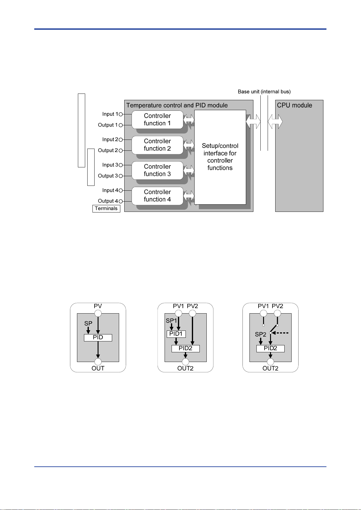
A1. Overview
The temperature control and PID module (hereafter called “the module”) is an I/O
module to be mounted on the FA-M3 base unit. The module is provided with
multiple input and output circuits and performs multiple PID control functions.
Figure A1.1 shows a schematic diagram of a system containing the module.
Thermocouple/RTD/Signal Converter
SSR/Relay/SCR
A1-1
Figure A1.1 Schematic Diagram Showing the Relationship between Sensors, Actuators,
Temperature Control and PID Module and CPU Module
The module is provided with four controller functions and one setup and control
interface for the controller functions for controlling four loops. The controller
functions can be configured to act inter-dependently or independently to support a
wide variety of applications.
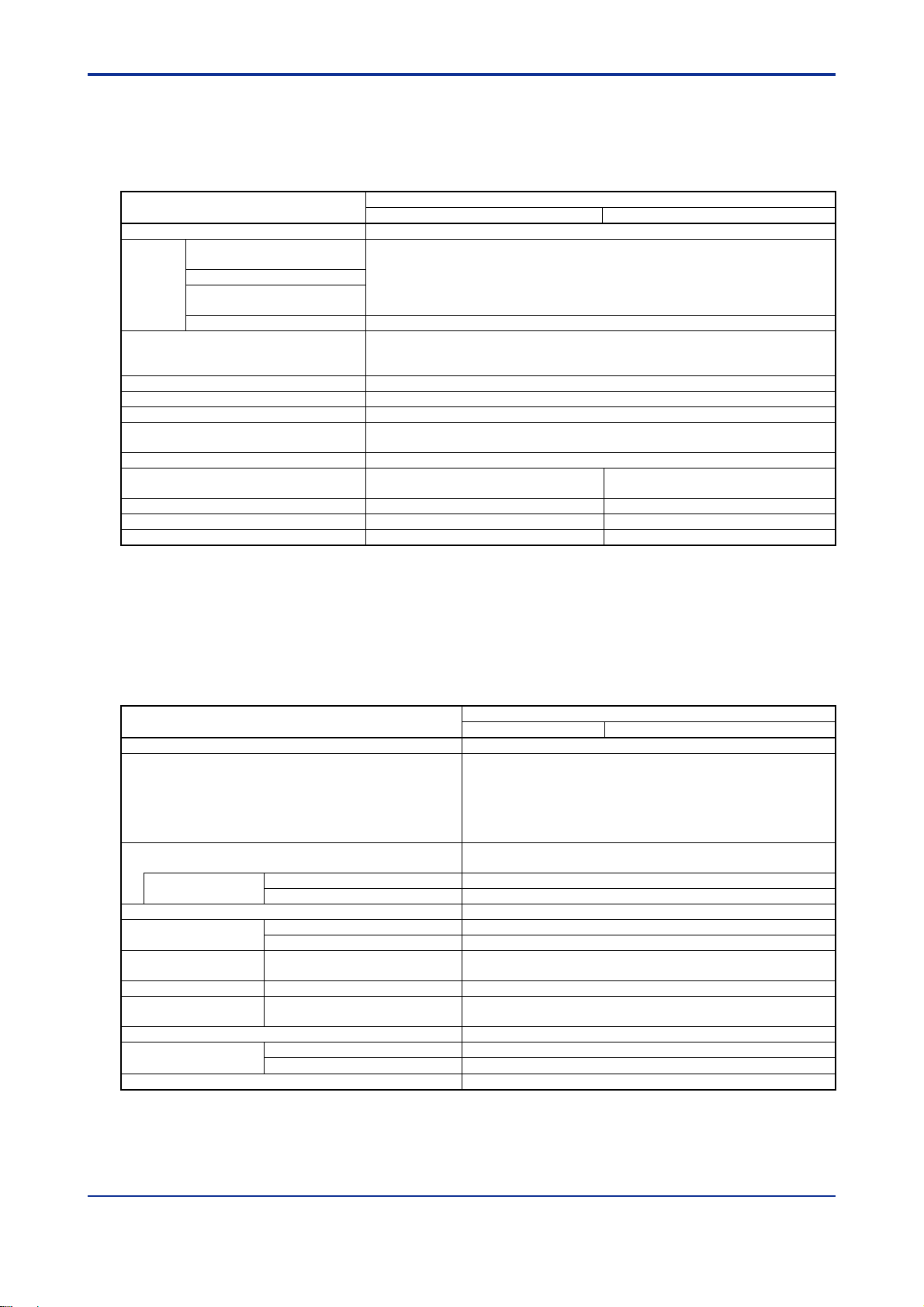
Three controller modes are available: single loop, cascade control, and two-input
changeover control. In the single loop mode (default), individual controller
functions operate independently. In the cascade or two-input changeover control
mode, two controller functions are combined to act as a single controller function.
(1) Single Loop (2) Cascade Control (3) Two-input Changeover Control
Figure A1.2 Controller Modes
Controller mode, instrument ranges, set points and other parameter values
required for module operation can be stored in the module to simplify operation
setup at each module startup. A program will then only need to run/stop operation
and switch between set points from the CPU module to achieve operation.
IM 34M06H62-02E 3rd Edition : Jul.16, 2015-00
Page 20

Features
- High accuracy, high resolution, high speed
The input sampling period for four loops is 200 ms. The sampling period may be set
to 100 ms if only two loops are used. The input conversion accuracy is 0.1% of full
scale, and the input resolution is 0.1C (using 5-digit representation). Low-resolution
operation (using 4-digit representation) is also available.
- Universal input
The input type may be set to thermocouple, RTD, or DC voltage for each loop.
- Dynamic auto-tuning
In the dynamic auto-tuning mode, what you have to do before starting operation is to
simply set the input type, output type, and set point. The dynamic auto-tuning
function automatically determines and tunes the PID parameters during operation.
You may disable the function, where appropriate.
Main Differences between F3CU04-N and F3CU04-S
With the F3CU04-S module, a specific SP backup procedure needs to be executed to
store set points to the EEPROM. Otherwise, set points are not stored to the EEPROM
when updated.
With the F3CU04-N module, however, set points are always stored automatically when
updated. This approach of storing set points unconditionally regardless of whether it is
required by an application allows for easier programming and operation, but may
damage the EEPROM storage media in an application where set points are constantly
updated.
A1-2
IM 34M06H62-02E 3rd Edition : Jul.16, 2015-00
Page 21

A2. Specifications
A2.1 Model and Suffix Codes
Table A2.1 shows the model name and suffix code of the module.
Table A2.1
Model
F3CU04
Model and Suffix Codes
Suffix
Code
-0S — —
-1S — —
Style
Code
Option
Code
4 loops
Universal input
Time-proportional PID output (open collector)
Single-slot size
4 loops
Universal input
Universal output (open collector, 4-20 mA continuous
output)
Double-slot size
A2-1
Description
A2.2 Compatibility with CPU Modules
There is no restriction on the type of CPU modules that can be used with this module.
IM 34M06H62-02E 3rd Edition : Jul.16, 2015-00
Page 22
* 2
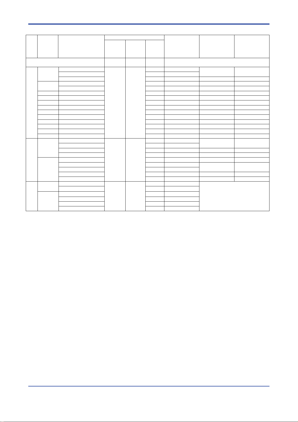
A2.3 General Specifications
Table A2.2 lists the general specifications of the F3CU04-0S and F3CU04-1S
temperature control and PID modules.
Table A2.2 General Specifications
Item
Number of loops 4
Isolation Between input terminals
Alarm types
Number of alarm outputs (input relays) 4 points per loop (only alarms 1 and 2 have input relays)
Alarm delay timer Yes
Warm-up time 30 minutes min.
Max. allowable ambient temperature
change rate
Mounting position Horizontal or inverted orientation not allowed
External connection
External dimensions
Current consumption 460 mA at 5 V DC 470 mA at 5 V DC
Weight 200 g 350 g
and internal circuit
Between input terminals
Between output terminals
and internal circuit
Between output terminals Not isolated.
*1
28.9 (W) x 100 (H) x 106.1 (D) mm 58 (W) x 100 (H) x 106.1 (D) mm
*1: The stated accuracy for the reference junction for thermocouple input deteriorates if the ambient temperature change
exceeds this rate.
*2: External dimensions excluding protrusions (for details, see the External Dimensions drawing).
Isolated by photocouplers and transformers
(tested for 1500 V AC voltage withstanding for 1 minute)
12 types of alarm:
Upper input limit, lower input limit, upper deviation limit, lower deviation limit,
upper/lower deviation limit, and deviation range, all with or without waiting
10C/h max.
One 18-point terminal block with
M3.5 screws
F3CU04-0S
Specification
Two 18-point terminal blocks with
M3.5 screws
A2-2
F3CU04-1S
A2.4 Input Specifications
Table A2.3 lists the input specifications of the F3CU04-0S and F3CU04-1S temperature
control and PID modules.
Table A2.3 Input Specifications
Item
Input sampling period*1 200ms for 4 loops, or 100ms for 2 loops
Input types and ranges
Burnout detection
Detection current
Input insulation resistance 1 M min.
Allowable signal
Source resistance
Allowable wiring
resistance
Measuring current RTD Approx. 270 μA
Reference junction
Compensation
Allowable input voltage range -20 to 20 V DC
Noise reduction
Effect of ambient temperature
*3*4
*1: If input sampling period is set to 100 ms for 2 loops, only loops 1 and 2 are available.
*2: This value assumes that all input terminals are correctly wired (that is, solderless termination, wire diameters and
connections are correct).
*3: This value assumes that the power supply frequency is correctly selected.
*4: This module continues to operate at a input accuracy of ±0.5% max. of F.S. during the radiated electromagnetic field test.
Thermocouple 100 nA max.
RTD 100 nA max.
Thermocouple or DC mV input 250
DC voltage input 2 k max.
RTD
*2
Thermocouple
Common mode 120 dB (50/60 Hz) min.
Normal mode 40 dB (50/60 Hz) min.
2.0C (0 to 55C)
F3CU04-0S
See Table A2.4, “Instrument Range and Accuracy”.
Individual inputs separately configurable by software or
collectively by hardware
Thermocouple input : 15 ranges
RTD input : 9 ranges
DC voltage input : 6 ranges
Thermocouples or RTDs are checked for burnout.
Up-scale, down-scale, or none may be selected.
max.
max. per wire
10
(three wires must have the same resistance)
0.01%/C or 1μV/C, whichever is greater
Specification
F3CU04-1S
IM 34M06H62-02E 3rd Edition : Jul.16, 2015-00
Page 23
*
6
*
6
*
7
*
7
*
8
*
8
*
9
*
9B*
10
*
10
*
10S*
11
*
11
*
11R*
11
*
11
*
11
*
12
*
12
*
13
*
13
*1
4
14
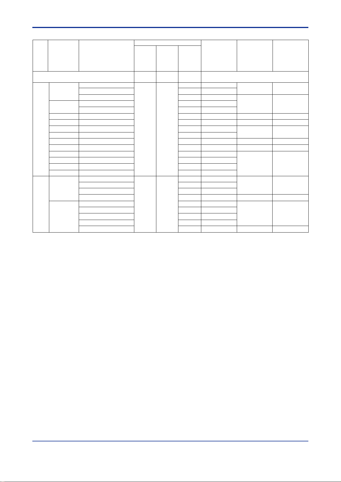
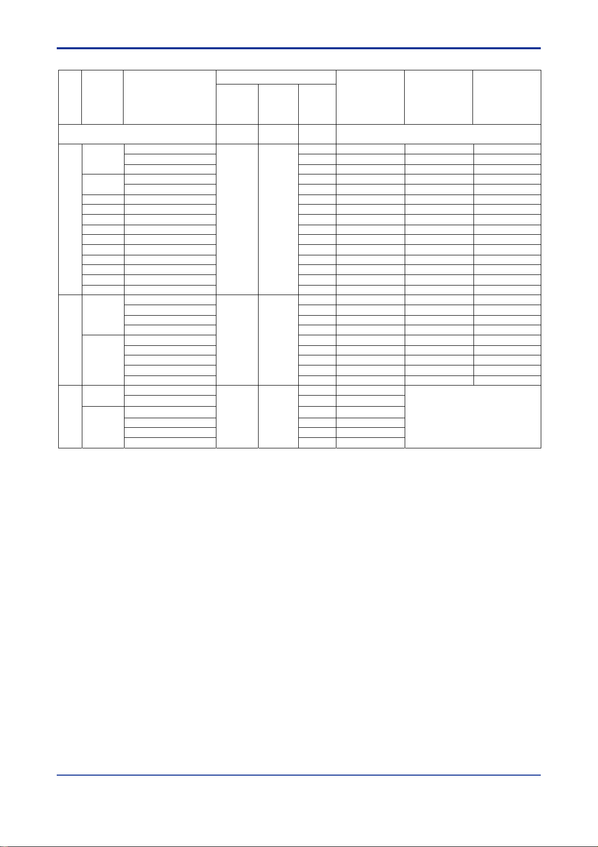
Table A2.4 Instrument Range and Accuracy (for high resolution operation with SW1-1 set to OFF) 1/4
Input Type Selector Switch
Input
Input
Type
Category
*1
Instrument Range
*2
SW1-3 SW1-4 SW5
*3
Software Setting
Accuracy*4 Resolution*2
A2-3
Software setting (factory setting) OFF OFF 0
-200.0 to 1370.0C
K*5
-200.0 to 1000.0C 2 2 ($02)
Instrument ranges
following codes.
1 1 ($01)
-200.0 to 500.0C 3 3 ($03)
J
-200.0 to 1200.0C 4 4 ($04)
-200.0 to 500.0C 5 5 ($05)
T -270.0 to 400.0C 6 6 ($06)
0.0 to 1600.0C 7 7 ($07)
0.0 to 1600.0C 8 8 ($08)
OFF OFF
0.0 to 1600.0C 9 9 ($09)
N -200.0 to 1300.0C A 10 ($0A)
Thermocouple
E -270.0 to 1000.0C B 11 ($0B)
L -200.0 to 900.0C C 12 ($0C)
U -200.0 to 400.0C D 13 ($0D)
W
0.0 to 1600.0C E 14 ($0E)
Platinel 2 0.0 to 1390.0C F 15 ($0F)
JPt100
-200.0 to 500.0C
-200.0 to 200.0C 1 17 ($11)
0.0 to 300.0C 2 18 ($12)
0 16 ($10)
0.00 to 150.00C 3 19 ($13)
RTD
Pt100
-200.0 to 850.0C 4
OFF ON
-200.0 to 500.0C 5 21 ($15)
-200.0 to 200.0C 6 22 ($16)
20 ($14)
0.0 to 300.0C 7 23 ($17)
0.00 to 150.00C 8 24 ($18)
DC mV
input
DC V
input
DC voltage
*1: Applicable standard is JIS/IEC/DIN (ITS-90) for thermocouples and RTD.
*2: For thermocouples K, B, S, R, and W, input ranges may be set wider than their instrument range (see the notes below). However, if the
input range width exceeds 1600C, the resolution becomes twice the indicated value. Furthermore, the actual range for an acceptable
input is the input range5%.
*3: When you turn on the power after changing the hardware switch settings, data stored in the EEPROM is initialized to follow the switch
settings.
*4: This accuracy applies if the ambient temperature is 25 5C and the input value is within the instrument range. If the input type is
thermocouple and reference junction compensation is used, you should also take into consideration the accuracy of the reference
junction compensation.
*5: For K-type thermocouples, the input range may be set from -270.0 to 1370.0C beyond its instrument range. The accuracy and
resolution depend on measured temperatures as follows:
-270.0 to -200.0C: Neither accuracy or resolution is guaranteed.
-200.0 to 0.0C: 1.0C accuracy, 0.2C resolution
*6: For K-type thermocouples, the accuracy and resolution depend on measured temperatures as follows:
-200.0 to -180.0C: 0.9C accuracy, 0.2C resolution
-180.0 to -100.0C: 0.6C accuracy, 0.1C resolution
*7: For J-type thermocouples, the accuracy and resolution depend on measured temperatures as follows:
-200.0 to -100.0C: 1.0C accuracy, 0.2C resolution
*8: For J-type thermocouples, the accuracy and resolution depend on measured temperatures as follows:
-200.0 to -150.0C: 0.6C accuracy, 0.1C resolution
*9: For T-type thermocouples, the accuracy and resolution depend on measured temperatures as follows:
-270.0 to -200.0C: 3.5C accuracy, 0.5C resolution
-200.0 to -100.0C: 1.0C accuracy, 0.1C resolution
*10: For B-type thermocouples, the input range may be set from 0.0 to 1800.0C beyond its instrument range. The accuracy and resolution
depend on measured temperatures as follows:
0.0 to 300.0C: Neither accuracy nor resolution is guaranteed.
300.0 to 900.0C: 2.5C accuracy, 0.3C resolution
*11: For S-type and R-type thermocouples, the input range may be set from 0.0 to 1700.0C beyond its instrument range. The accuracy and
resolution depend on measured temperatures as follows:
0.0 to 200.0C: 1.5C accuracy, 0.2C resolution
*12: For N-type thermocouples, the accuracy and resolution depend on measured temperatures as follows:
-200.0 to 0.0C: 1.3C accuracy, 0.3C resolution
*13: For E-type thermocouples, the accuracy and resolution depend on measured temperatures as follows:
-270.0 to -200.0C: 6.5C accuracy, 2.0C resolution
-200.0 to -100.0C: 1.0C accuracy, 0.2C resolution
*14: For W-type thermocouples, the input range may be set from 0.0 to 2300.0C beyond its instrument range. The accuracy and resolution
depend on measured temperatures as follows:
0.0 to 100.0C: 1.0C accuracy, 0.2C resolution
*15: Resolution is determined by the upper and lower limits for the input range, as well as the upper and lower scaling limits. It is represented
by one digit.
*16: "" means that the value is ignored.
0 to 10.00 mV DC
*15
0 to 100.0 mV DC A 26 ($1A)
0.000 to 1.000 V DC B 27 ($1B)
0.000 to 5.000 V DC D 29 ($1D)
*15
1.000 to 5.000 V DC E 30 ($1E)
*16
ON
0.00 to 10.00 V DC F 31 ($1F)
9 25 ($19)
may be specified by software using one of the
*5
0.5C
0.1C*5
0.5C
0.1C
0.5C
0.1C
0.5C
0.1C
0.5C
0.1C
1.0C
0.1C
1.0C
0.1C
1.0C
0.1C
0.6C
0.1C
0.5C
0.1C
0.6C 0.1C
0.6C 0.1C
0.8C14 0.1C
0.6C 0.1C
0.4C 0.1C
0.3C 0.1C
0.20C 0.03C
0.4C 0.1C
0.4C 0.1C
0.3C 0.1C
0.20C 0.03C
0.1% of instrument range
*15
1 digit
IM 34M06H62-02E 3rd Edition : Jul.16, 2015-00
Page 24
*
6
*
7
*
7
*
7
*
8
*
9
*
9
*
10
*
10
*
11
Table A2.4 Instrument Range and Accuracy (for low resolution operation with SW1-1 set to OFF) 2/4
Input
Category
Input Type
Input Type Selector Switch
*1
Instrument Range
SW1-3 SW1-4 SW5
*3
Software
Setting
Accuracy
*4
Resolution*2
A2-4
Software setting ON OFF 0
-200 to1370C
K*5
-200 to1000C 2 34 ($22)
Instrument ranges may be specified by
software using one of the following codes.
1 33 ($21)
2C
*5
1C*5
-200 to500C 3 35 ($23)
J
-200 to 1200C 4 36 ($24)
-200 to 500C 5 37 ($25)
T -270 to 400C 6 38 ($26)
B
0 to 1600C 7 39 ($27)
S
0 to 1600C 8 40 ($28)
R
0 to 1600C 9 41 ($29)
N -200 to 1300C A 42 ($2A)
Thermocouple
ON OFF
E -270 to 1000C B 43 ($2B)
2C 1C
2C
1C
2C
1C
2C 1C
2C
1C
2C
1C
L -200 to 900C C 44 ($2C)
U -200 to 400C D 45 ($2D)
W
0 to 1600C E 46 ($2E)
2C 1C
Platinel 2 0 to 1390C F 47 ($2F)
RTD
JPt100
Pt100
-200 to 500C
-200 to 200C 1 49 ($31)
0 to 300C 2 50 ($32)
0.0 to 150.0C 3 51 ($33)
-200 to 850C 4 52 ($34)
ON ON
-200 to 500C 5 53 ($35)
-200 to 200C 6 54 ($36)
0 48 ($30)
2C 1C
0.3C 0.1C
2C 1C
0 to 300C 7 55 ($37)
0.0 to 150.0C 8 56 ($38)
*1: Applicable standard is JIS/IEC/DIN (ITS-90) for thermocouples and RTD.
*2: For thermocouples K, B, S, R, and W, input ranges may be set wider than their instrument range (see the notes below). Furthermore, the
actual range for an acceptable input is the input range5%.
*3: When you turn on the power after changing the hardware switch settings, data stored in the EEPROM is initialized to follow the switch
settings.
*4: This accuracy applies if the ambient temperature is 25 5C and the input value is within the instrument range. If the input type is
thermocouple and reference junction compensation is used, you should also take into consideration the accuracy of the reference
junction compensation.
*5: For K-type thermocouples, the upper and lower input range limits may be set from -270 to 1370C. The accuracy and resolution depend
on measured temperatures as follows:
-270 to -200C: Neither accuracy nor resolution is guaranteed.
*6: For T-type thermocouples, the accuracy and resolution depend on measured temperatures as follows:
-270 to -200C: 4C accuracy, 1C resolution
*7: For B-type thermocouples, the upper and lower input range limits may be set from 0 to 1800C. The accuracy and resolution depend on
measured temperatures as follows:
0 to 300C: Neither accuracy nor resolution is guaranteed.
300 to 900C: 3C accuracy, 1C resolution
*8: For S-type and R-type thermocouples, the upper and lower input range limits may be set from 0 to 1700C.
*9: For N-type thermocouples, the accuracy and resolution depend on measured temperatures as follows:
-200 to 0C: 3C accuracy, 1C resolution
*10: For E-type thermocouples, the detailed accuracy and resolution are as follows:
-270 to -200C: 8C accuracy, 2C resolution
-200 to 1000C: 2C accuracy, 1C resolution
*11: For W-type thermocouples, the upper and lower input range limits may be set from 0 to 2300C.
0.3C 0.1C
IM 34M06H62-02E 3rd Edition : Jul.16, 2015-00
Page 25
*
5
*
5
*
5
*
5
*
6
*
6
*
7
*
7
*
8
*
9
*
9
*
10
*
10
*
10
*
11
*
11
*
11
*
11
*
12
*
12
*
13
*
13
*1
4
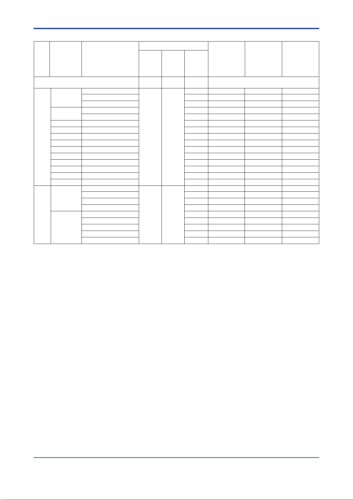
Table A2.4 Instrument Range and Accuracy (for high resolution operation with SW1-1 set to ON) 3/4
*3
Software
Setting
Accuracy
*4
Resolution*2
Input
Category
Input
Type
*1
Instrument Range
Input Type Selector Switch
*2
SW1-3 SW1-4 SW5
A2-5
Software setting (factory setting) OFF OFF 0
-328.0 to 2498.0F
K*5
-328.0 to 1832.0F
-328.0 to 932.0F
J
T
B
S
R
N
Thermocouple
E
L
U
W
Platinel 2
-328.0 to 2192.0F
-328.0 to 932.0F
-454.0 to 752.0F
32 to 2912F
32 to 2912F
32 to 2912F
-328.0 to 2372.0F
-454.0 to 1832.0F
-328.0 to 1652.0F
-328.0 to 752.0F
32 to 2912F
32.0 to 2534.0F
OFF OFF
-328.0 to 932.0F
JPt100
-328.0 to 392.0F
32.0 to 572.0F
32.0 to 302.0F
RTD
Pt100
-328.0 to 1562.0F
-328.0 to 932.0F
-328.0 to 392.0F
OFF ON
32.0 to 572.0F
32.0 to 302.0F
DC mV
*15
input
DC V
*15
input
DC voltage
*1: Applicable standard is JIS/IEC/DIN (ITS-90) for thermocouples and RTD.
*2: For thermocouples K, B, S, R, and W, input ranges may be set wider than their instrument range (see the notes below). However, if the
input range width exceeds 2880F, the resolution becomes twice the indicated value. Furthermore, the actual range for an acceptable
input is the input range5%.
*3: When you turn on the power after changing the hardware switch settings, data stored in the EEPROM is initialized to follow the switch
settings.
*4: This accuracy applies if the ambient temperature is 77F9F and the input value is within the instrument range. If the input type is
thermocouple and reference junction compensation is used, you should also take into consideration the accuracy of the reference
junction compensation.
*5: For K-type thermocouples, the input range may be set from -454.0 to 2498.0F beyond its instrument range. The accuracy and resolution
depend on measured temperatures as follows:
-454.0 to -328.0F: Neither accuracy or resolution is guaranteed.
-328.0 to 32.0F: 2.0F accuracy, 0.4F resolution
*6: For K-type thermocouples, the accuracy and resolution depend on measured temperatures as follows:
-328.0 to -292.0F: 2.0F accuracy, 0.4F resolution
-292.0 to -148.0F: 1.2F accuracy, 0.2F resolution
*7: For J-type thermocouples, the accuracy and resolution depend on measured temperatures as follows:
-328.0 to -148.0F: 2.0F accuracy, 0.4F resolution
*8: For J-type thermocouples, the accuracy and resolution depend on measured temperatures as follows:
-328.0 to -238.0F: 1.2F accuracy, 0.2F resolution
*9: For T-type thermocouples, the accuracy and resolution depend on measured temperatures as follows:
-454.0 to -328.0F: 6.5F accuracy, 1.0F resolution
-328.0 to -148.0F: 2.0F accuracy, 0.2F resolution
*10: For B-type thermocouples, the input range may be set from 32 to 3272F beyond its instrument range. The accuracy and resolution
depend on measured temperatures as follows:
32 to 572F: Neither accuracy nor resolution is guaranteed.
572 to 1652F: 5F accuracy, 1F resolution
*11: For S-type and R-type thermocouples, the input range may be set from 32 to 3092F beyond its instrument range. The accuracy and
resolution depend on measured temperatures as follows:
32 to 392F: 3F accuracy, 1F resolution
*12: For N-type thermocouples, the accuracy and resolution depend on measured temperatures as follows:
-328.0 to 32.0F: 2.5F accuracy, 0.6F resolution
*13: For E-type thermocouples, the accuracy and resolution depend on measured temperatures as follows:
-454.0 to -328.0F: 12.0F accuracy, 4.0F resolution
-328.0 to -148.0F: 2.0F accuracy, 0.4F resolution
*14: For W-type thermocouples, the input range may be set from 32 to 4172F beyond its instrument range.
*15: Resolution is determined by the upper and lower limits for the input range, as well as the upper and lower scaling limits. It is represented
by one digit.
*16: "" means that the value is ignored.
0 to 10.00 mV DC
0 to 100.0 mV DC
0.000 to 1.000 V DC
0.000 to 5.000 V DC
1.000 to 5.000 V DC
0.00 to 10.00 V DC
*16
ON
Instrument ranges may be specified by software
using one of the following codes.
1.0F
1 1 ($01)
2 2 ($02) 1.0F
3 3 ($03) 1.0F
4 4 ($04) 1.0F
5 5 ($05) 1.0F
6 6 ($06) 1.0F
7 7 ($07) 2F
8 8 ($08) 2F
9 9 ($09) 2F
A 10 ($0A) 1.2F
B 11 ($0B) 1.0F
0.2F
0.2F
0.2F
0.2F
0.2F
0.2F
1F
1F
1F
0.2F
0.2F
C 12 ($0C) 1.2F 0.2F
D 13 ($0D) 1.2F 0.2F
E 14 ($0E) 2F 1F
F 15 ($0F) 1.2F 0.2F
0 16 ($10)
1 17 ($11)
2 18 ($12)
3 19 ($13)
4 20 ($14)
5 21 ($15)
6 22 ($16)
7 23 ($17)
0.8F 0.2F
0.8F 0.2F
0.6F 0.2F
0.4F 0.2F
0.8F 0.2F
0.8F 0.2F
0.8F 0.2F
0.6F 0.2F
8 24 ($18) 0.4F 0.2F
9 25 ($19)
A 26 ($1A)
B 27 ($1B)
D 29 ($1D)
0.1% of instrument range
1 digit
*15
E 30 ($1E)
F 31 ($1F)
IM 34M06H62-02E 3rd Edition : Jul.16, 2015-00
Page 26
*
5
*
5
*
5
*
5
*
6
*
7
*
7
*
7
*
8
*
8
*
8
*
8
*
9
*
10
*
10
*
11
Table A2.4 Instrument Range and Accuracy (for low resolution operation with SW1-1 set to ON) 4/4
Input
Category
Input Type
Input Type Selector Switch
*1
Instrument Range
SW1-3 SW1-4 SW5
*3
Software
Setting
Accuracy
*4
Resolution*2
A2-6
Software setting ON OFF 0
-328 to 2498F
K*5
-328 to 1832F
-328 to 932F
-328 to 2192F
-328 to 932F
-454 to 752F
32 to 2912F
32 to 2912 F
32 to 2912F
-328 to 2372F
-454 to 1832F
-328 to 1652F
-328 to 752F
32 to 2912F
32 to 2534F
ON OFF
Thermocouple
J
T
B
S
R
N
E
L
U
W
Platinel 2
-328 to 932F
JPt100
-328 to 392F
32 to 572F
32 to 302F
RTD
Pt100
-328 to 1562F
-328 to 932F
-328 to 392F
ON ON
32 to 572F
32 to 302F
*1: Applicable standard is JIS/IEC/DIN (ITS-90) for thermocouples and RTD.
*2: For thermocouples K, B, S, R, and W, input ranges may be set wider than their instrument range (see the notes below). Furthermore, the
actual range for an acceptable input is the input range5%.
*3: When you turn on the power after changing the hardware switch settings, data stored in the EEPROM is initialized to follow the switch
settings.
*4: This accuracy applies if the ambient temperature is 77F9F and the input value is within the instrument range. If the input type is
thermocouple and reference junction compensation is used, you should also take into consideration the accuracy of the reference
junction compensation.
*5: For K-type thermocouples, the upper and lower input range limits may be set from -454 to 2498F. The accuracy and resolution depend
on measured temperatures as follows:
-454 to 328F: Neither accuracy nor resolution is guaranteed.
*6: For T-type thermocouples, the accuracy and resolution depend on measured temperatures as follows:
-454 to -328F: 7F accuracy, 1F resolution
*7: For B-type thermocouples, the upper and lower input range limits may be set from 32 to 3272F. The accuracy and resolution depend on
measured temperatures as follows:
32 to 572F: Neither accuracy nor resolution is guaranteed.
572 to 1652F: 5F accuracy, 1F resolution
*8: For S-type and R-type thermocouples, the upper and lower input range limits may be set from 32 to 3092F. The accuracy and
resolution depend on measured temperatures as follows:
32 to 392F: 3F accuracy, 1F resolution
*9: For N-type thermocouples, the accuracy and resolution depend on measured temperatures as follows:
-328 to 32F: 4F accuracy, 1F resolution
*10: For E-type thermocouples, the detailed accuracy and resolution are as follows:
-454 to 328F: 12F accuracy, 4F resolution
-328 to 148F: 3F accuracy, 1F resolution
*11: For W-type thermocouples, the upper and lower input range limits may be set from 32 to 4172F.
Instrument ranges may be specified by
software using one of the following codes.
1 33 ($21)
2 34 ($22)
3 35 ($23)
4 36 ($24)
5 37 ($25)
6 38 ($26) 2F
7 39 ($27) 2F
8 40 ($28) 2F
9 41 ($29) 2F
A 42 ($2A) 2F
B 43 ($2B) 2F
2F
1F
2F
1F
2F 1F
2F 1F
2F 1F
1F
1F
1F
1F
1F
1F
C 44 ($2C) 2F 1F
D 45 ($2D) 2F 1F
E 46 ($2E) 2F 1F
F 47 ($2F) 2F 1F
0 48 ($30)
1 49 ($31)
2 50 ($32)
3 51 ($33)
4 52 ($34)
5 53 ($35)
6 54 ($36)
7 55 ($37)
8 56 ($38)
2F 1F
2F 1F
2F 1F
2F 1F
2F 1F
2F 1F
2F 1F
2F 1F
2F 1F
IM 34M06H62-02E 3rd Edition : Jul.16, 2015-00
Page 27
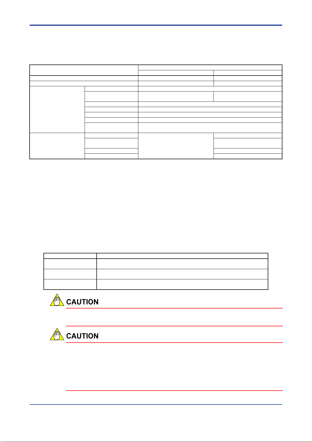
A2.5 Output Specifications
Table A2.5 lists the output specifications of the F3CU04-0S and F3CU04-1S temperature
control and PID modules.
Table A2.5 Output Specifications
Item
Number of outputs 4 8
External power supply * 24 V DC 10%, 10 mA 24 V DC 10%, 250 mA
Rated load voltage 24 V DC
Maximum load current 0.1 A per point
Time-proportional PID
output (open collector
output)
Continuous PID output
(analog output)
* External power supply is not required if no output terminal is used (that is, if only input terminals are used).
ON residual voltage 0.5 V DC max.
OFF leakage current 0.1 mA max.
Response time OFFON: 1 ms max., ONOFF: 1 ms max.
Cycle time 0.5 to 240 s
Time-proportional
resolution
Output range
Allowable load
resistance
Output accuracy
Output resolution 0.05% of F.S.
10 ms or 0.05% of F.S., whichever is greater
N.A.
F3CU04-0S
Specification
F3CU04-1S
0.1 A per point and 0.4 A for 8
points
4-20 mA (3.2-20.8 mA)
600 max.
1.0% of F.S.
A2-7
A2.6 Backup Function
The F3CU04-0S or F3CU04-1S temperature control and PID module provides a backup
function for storing input type, input range, set points and other parameter values, and
hence retaining their values even after power off and on. Parameters designated for
backup are stored whenever their corresponding registers are updated, provided the
backup function is not disabled. However, you need to execute a specific procedure
every time to back up set point values. Otherwise, stored set points will not be updated.
Even so, beware that set points will not be updated if the backup function is disabled.
Take note that there is a maximum limit to the number of write operations allowed for the
backup function.
Table A2.6 Backup Function
Description
Stored parameters
Number of write
operations
Disable backup function
For details on the I/O data registers that are stored by the backup function and their data
position numbers, see Section B2, "Types of Relays and Registers."
Controller parameters, I/O parameters, and operation parameters. For details, refer
to the list of registers.
Up to 100,000 write operations allowed
This parameter disables the backup function. It may be used, if required, to avoid
reaching the maximum limit for write operations.
In situations where the CPU module frequently overwrites the I/O data registers
earmarked to be stored by the backup function, the maximum limit for write operations
(100,000 times) may be reached. To prevent this, turn on the Disable Backup Function
parameter. Once the write limit is reached, data backup is no longer allowed and the
system enters hardware failure mode. Furthermore, parameter data may be reset at
system startup to the default values given in Section B2, "Types of Relays and
Registers."
IM 34M06H62-02E 3rd Edition : Jul.16, 2015-00
Page 28
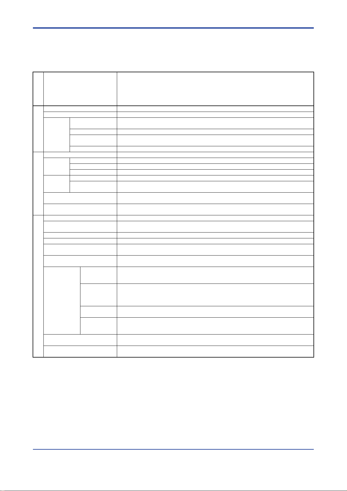
A2.7 Function Specifications
Table A2.7 shows the function specifications of the F3CU04-0S and F3CU04-1S
temperature control and PID modules.
Table A2.7 Function List (1/2)
Functions Description
Category
Input sampling period Sets the input sampling period (this affects the number of available loops).
Controller mode selection Specifies the controller mode for a pair of 2 loops.
Single loop
Controller
Controller
mode
Control type selection Selects from on/off, PID, and heating/cooling control types.
Control
type
Output
limiter
Output type selection *2
Output processing
Cascade control Two control and computation functions perform cascade control (using 2 loops of input and output).
Two-input
changeover
Disabled Loops specified as ‘disabled’ are not used.
ON/OFF
PID Controls output according to PID computation results.
Heating/cooling Controls both heating and cooling outputs according to PID computation results.
Output limiter
Rate-of-change
limit
Analog output *2
Input type selection Sets input type using switches (for all loops) or software (for individual loops).
Power supply frequency
specification
Input range setting Sets input ranges.
PV range setting Sets PV range for two-input changeover mode.
Burnout selection
Reference junction
compensation
Broken-line
biasing
Input
Input processing
computation
Fixed biasing
Input filtering
Square root
extraction
Two-input changeover
External PV input
*1: Numbers within parentheses (100% and 0%) applies when the output is configured as a continuous output
(for F3CU04-1S only).
*2: Available for F3CU04-1S only.
*3: When burnout selection is set to OFF, the measured input value at the time of burnout (open circuit) is unpredictable and
may approach either the upper limit or the lower limit. Furthermore, the burnout relay is not set.
However +OVER or -OVER detection is performed.
Basic controller mode with one control and computation function where two loops operate
independently.
Switches between two measured inputs (using a register or measured value range) and handles
them as one measured input (using 2 loops of input).
Performs control by turning on (100% output) or turning off the output (0% output). *
Sets the upper and lower limits for the control output.
Sets the maximum allowable rate-of-change for the control output.
Selects between time-proportional output (open collector) and continuous output (4-20 mA analog
output).
Specifies a fixed value output for any output terminal not used in a control loop (e.g. when
disabled).
Specifies the power supply frequency. An appropriate setting value will reduce the effect of common
mode noise.
Selectable from Up-scale, Down-scale, or OFF (no burnout detection) for thermocouple or RTD
input open-circuit detection. *3
Sets thermocouple reference junction compensation to ‘On’ or ‘Fixed Value’.
Specifies any temperature and its bias value. A compensation value based on the linear
interpolation of the specified bias values is automatically added to a measured input. This function
is particularly useful for a deteriorated sensor, for which input compensation is desirable.
Specifies a fixed bias value to be automatically added to measured input values. This function is
useful when a measured input suffers a fixed deviation due to a known physical problem with a
sensor, or when fine adjustment of measured input is desirable for better consistency with values
indicated by other equipment, even though data deviation is within tolerance.
Filtering can be used to remove high frequency noise from measured inputs such as flow rate and
pressure. Filtering is a first order delay numerical operation.
Performs square root extraction on measured inputs. This function is useful for converting
differential pressure signals (of orifice, nozzle, or other types of restriction flowmeter) to flow rate
signals.
Sets the two-input changeover mode to perform changeover based on temperature range, preset
temperature value, or register value.
External values may be used as control input values. Measured input values that have undergone
required processing by a CPU module or other means, may be used as input values.
A2-8
1
IM 34M06H62-02E 3rd Edition : Jul.16, 2015-00
Page 29

Table A2.7 Function List (2/2)
Functions Description
Category
Four set points can be predefined for each loop. A predefined set point can be selected using the
SP number parameter.
Defines acceleration and deceleration independently for varying the control set point at a fixed rate
or to prevent an abrupt change in the control set point.
When a switchover is made from Stop to Run, from Manual to Automatic, or from one SP number to
another, the control set point is first set to the current PV value and then gradually changed to the
required value at the rate defined by the SP gradient parameters.
Automatically recalculates PID constants to achieve continuous stable control at the beginning of a
control operation or when control becomes unstable.
When a start tuning instruction is issued, measures the characteristics of a control object by
switching on and then switching off the output, and automatically determines and sets optimal PID
constants.
Defines the direction of output change (increase or decrease) corresponding to a positive deviation.
The combination of the CMD parameter (0: standard PID control mode, 1: fixed-point control mode)
and the remote/local switch determines the PID control method (PV derivative type PID control or
deviation derivative type PID control) with or without bumping.
Prevents excessive integration and hence overshooting by suspending PID computation. The
deviation width for resuming PID computation can be set using a parameter.
Set point
Autotuning
Control
and
Control and computation
computation
Set points
Remote set point Can be used to continually change the set point value from the CPU module or by other means.
SP tracking Retains the set point value when switching from remote to local mode.
SP limiter Limits the set point within specified limits in remote or cascade control mode.
SP gradient
setting
PV tracking
Dynamic
auto-tuning
Auto-tuning
Forward/reverse
operation
PID control mode
Super Suppresses overshooting using fuzzy logic.
Anti-reset windup
PID selection Selects one of the four PID parameter groups belonging to each loop.
PID
selection
method
SP number
selection
Zone PID selection
Switches between four PID parameter groups according to the value of the SP Number Selection
parameter.
Automatically switches between PID parameter groups according to PV value. In addition, allows
switching to a specific PID parameter group when the deviation is large.
Operation control Switches between run/stop, automatic/manual/cascade, remote/local, and other operating modes.
Alarm setup
Alarm
Alarm
Waiting Suppresses alarms during the startup period after power on until the operation stabilizes.
Delay timer Reports an alarm only if an alarm condition persists for a minimum duration.
Backup function
(Storing of preset values)
Defines four alarms for each loop. Alarms may be defined to trigger with respect to the upper or
lower input limit or differential upper or lower limit.
Stores parameters to the EEPROM, which is writable up to 100,000 times.
A2-9
IM 34M06H62-02E 3rd Edition : Jul.16, 2015-00
Page 30
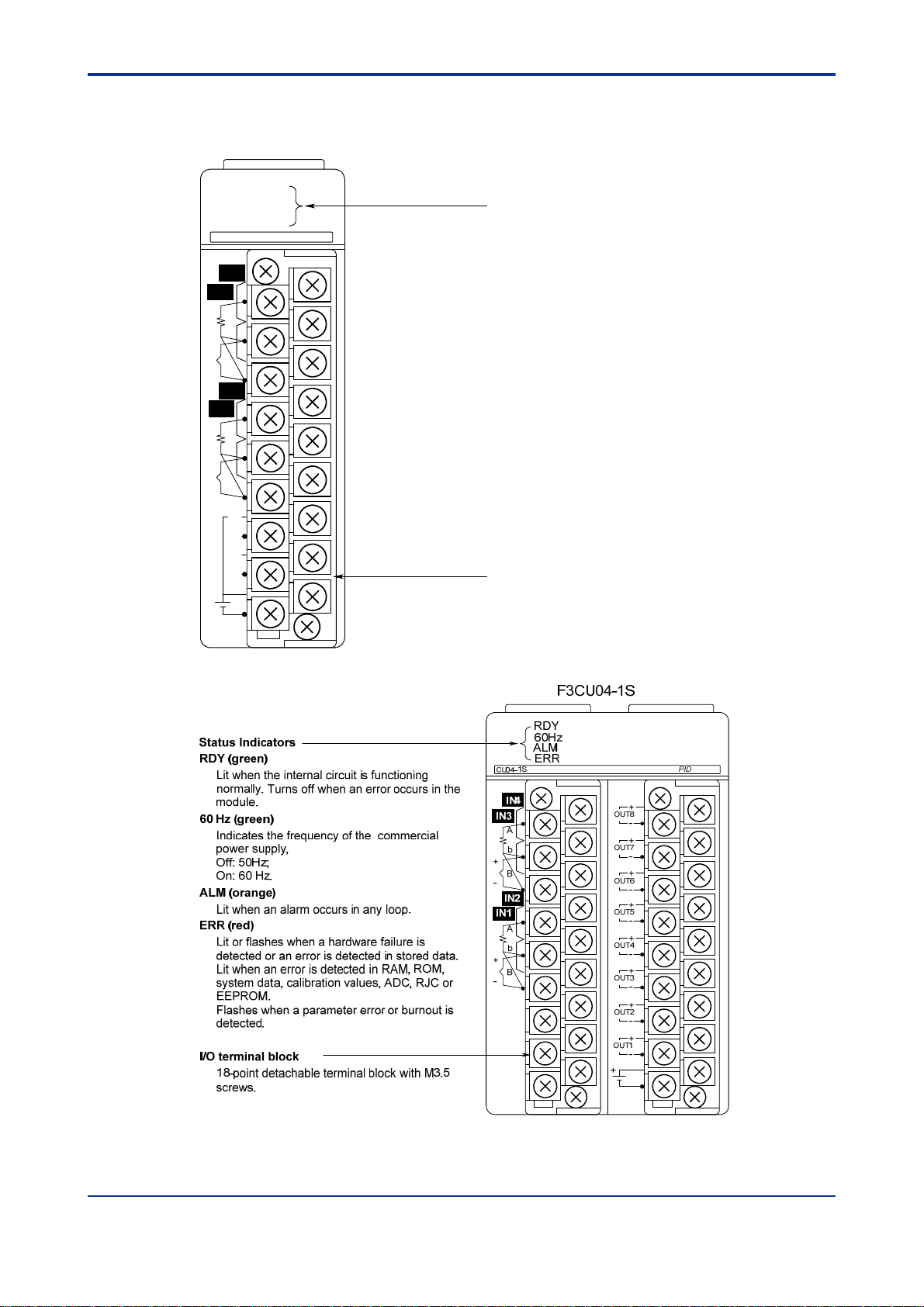
A2.8 Components and Functions
F3CU04-0S
RDY
CU04-0S
IN4
IN3
A
b
+
B
-
IN2
IN1
A
b
+
B
-
4
3
2
1
OUT
COM
60Hz
ALM
ERR
PID
Status Indicators
RDY (green)
Lit when the internal circuit is functioning
normally. Turns off when an error occurs in the
module.
60 Hz (green)
Indicates the frequency of the commercial
power supply,
Off: 50Hz;
On: 60 Hz.
ALM (orange)
Lit when an alarm occurs in any loop.
ERR (red)
Lit or flashes when a hardware failure is
detected or an error is detected in stored data.
Lit when an error is detected in RAM, ROM,
system data, calibration values, ADC, RJC or
EEPROM.
Flashes when a parameter error or burnout is
detected.
I/O terminal block
18-point detachable terminal block with M3.5
screws.
A2-10
Figure A2.1 F3CU04-0S, F3CU04-1S Front View
IM 34M06H62-02E 3rd Edition : Jul.16, 2015-00
Page 31

Figure A2.2 Right Side View Showing Input Type and Power Supply Frequency Selector
A2-11
Switches
You may switch the temperature unit between C and F using SW1-1. For details, see
Section C11, “Selecting Temperature Unit.”
A2.9 External Dimensions
Figure A2.3 External Dimensions
IM 34M06H62-02E 3rd Edition : Jul.16, 2015-00
Page 32

Blank Page
Page 33

A3. Startup Procedure
Install the module into your system and perform the following startup procedure.
Figure A3.1 Startup Procedure
Before you use the module, you must first design the overall system
configuration, set the switches, install the module on the base unit, and perform
required wiring and other hardware preparation. Following that, you will set the
controller modes and input ranges using software. The software here refers to the
FA-M3 Programming Tool WideField3, the BASIC Programming Tool M3 or the
ToolBox for Temperature Control and Monitoring modules. The required system
components when performing setup are the power supply module, the base
module, the CPU module, software and a personal computer for running the
software. For details on the required environment for executing the software,
including specifications for the personal computer and compatible CPU modules,
as well as details on how to operate the software, see the relevant software
manuals.
After software setup, perform trial runs to tune parameters for optimal
performance. Now, you are ready for actual operation.
Sections A4, "Hardware Preparation" and B3, "Setup and Operation" describe
these procedures in detail. For details on how to access the module using
software to perform setup and for more information on relays and registers, see
Section B1, "Accessing the Module," and B2, "Types of Relays and Registers,"
respectively.
A3-1
IM 34M06H62-02E 3rd Edition : Jul.16, 2015-00
Page 34

Blank Page
Page 35

A4. Hardware Preparation
To use the temperature control and PID module, you must set the operation
switches and perform wiring connections. In this chapter, we describe the details
of hardware preparation.
Figure A4.1 shows the workflow for hardware preparation. For details on each
operation, refer to the sections indicated in the column on the right.
Figure A4.1 Workflow for Hardware Preparation
A4-1
IM 34M06H62-02E 2nd Edition : June 2008-00
Page 36

A4.1 Selecting Input Types and Power
Frequency
This section describes how to select appropriate input types for given temperature ranges
and how to select a suitable power frequency for a given power supply environment.
Figure A4.2 shows the hardware switches for selecting input types and power frequency.
SW1-1: Temperature unit selector switch
SW1-2: Power frequency selector switch
SW1-3: Input type selector switch
SW1-4: Input type selector switch
SW5: Input type selector switch
(Input type is determined by the
combined values of SW1-3, SW1-4, and SW5.)
A4-2
Note: This is the right side view of the module with its cover removed.
Figure A4.2 Input Types and Power Frequency Selector Switches
Use switches SW1-1, SW1-3, SW1-4 and SW5 to perform input setup. SW1-4 and SW5
together specifies an input type, which apply to all loops, while SW1-3 specifies a
resolution and SW1-1 specifies the temperature unit for all loops. For the various switch
combinations and their corresponding input type and resolution values, see Table 4.1,
“Input Type Selection”.
Use SW1-2 to select a power frequency corresponding to the AC power used in the
equipment. For the mapping between SW1-2 and frequency, see Table 4.2, “Power
Frequency Settings”. Selecting an appropriate power frequency will reduce interference
from common mode noise.
You can also set input types and power frequenc y using data registers. To do so, set the
input type selector switches to “set by software”, that is, “SW5=0; SW1-4=OFF”. This will
mean that the power frequency will also have to be set using data registers. The factory
switch setting is “set by software.”
For details on input type selection and power frequency selection, see Section C3.1,
“Input Type Selection” and Section C3.2, “Power Frequency Selection” respectively.
Always turn off the power before performing switch setup.
You may switch the temperature unit between C and F using SW1-1. For details, see
Section C11, “Selecting Temperature Unit.”
IM 34M06H62-02E 2nd Edition : June 2008-00
Page 37

RL RH
RH
Table A4.1 Input Type Selection (1/2) (SW1-1 = OFF)
Input Type Instrument Range
Software setting *4 0 OFF X
K
-200.0 to 1370.0C 1
-200.0 to 1000.0C 2
-200.0 to 500.0C 3
J
-200.0 to 1200.0C 4
-200.0 to 500.0C 5
T
-270.0 to 400.0C 6
B
0.0 to 1600.0C 7
S
0.0 to 1600.0C 8
R
Thermocouple
Platinel 2
JPt100
Pt100
RTD
0-10mV 0.00 to 10.00 mV 9
0-100mV 0.0 to 100.0 mV A 26 ($1A) 0 1000 1 0 1000
0-1V 0.000 to 1.000 V B 27 ($1B) 0 1000 3 0 1000
0-5V 0.000 to 5.000 V D 29 ($1D) 0 5000 3 0 5000
1-5V 1.000 to 5.000 V E 30 ($1E) 1000 5000 3 1000 5000
DC voltage
0-10V 0.00 to 10.00 V F 31 ($1F) 0 1000 2 0 1000
*1: For thermocouples K, B, S, R, and W, the upper and lower input range limits may exceed their default values.
*2: When you change the switch settings and then power on the module, all stored data is initialized according to the hardware switch
*3: “Software Setting” refers to values specified for input type selection (IN). Any value not listed here is ignored.
*4: These are factory settings. When ‘set by software’ is selected, the initial value of input type selection (IN) is “1: Thermocouple K”.
0.0 to 1600.0C 9
N
-200.0 to 1300.0C A
E
-270.0 to 1000.0 C B
L
-200.0 to 900.0C C
U
-200.0 to 400.0C D
W
0.0 to 1600.0C E
0.0 to 1390.0C F
-200.0 to 500.0C 0
-200.0 to 200.0C 1
0.0 to 300.0C 2
0.00 to 150.00C 3
-200.0 to 850.0C 4
-200.0 to 500.0C 5
-200.0 to 200.0C 6
0.0 to 300.0C 7
0.00 to 150.00C 8
settings. An ‘X’ symbol in the SW1-3 column indicates that the switch setting is ignored.
Input Type
Selector Switch*2
SW5 SW1-4 SW1-3
OFF
OFF 1 ($01) -2000 13700 1 -2700 13700
ON 33 ($21) -200 1370 0 -270 1370
OFF 2 ($02) -2000 10000 1 -2700 13700
ON 34 ($22) -200 1000 0 -270 1370
OFF 3 ($03) -2000 5000 1 -2000 5000
ON 35 ($23) -200 500 0 -200 500
OFF 4 ($04) -2000 12000 1 -2000 12000
ON 36 ($24) -200 1200 0 -200 1200
OFF 5 ($05) -2000 5000 1 -2000 5000
ON 37 ($25) -200 500 0 -200 500
OFF 6 ($06) -2700 4000 1 -2700 4000
ON 38 ($26) -270 400 0 -270 400
OFF 7 ($07) 0 16000 1 0 18000
ON 39 ($27) 0 1600 0 0 1800
OFF 8 ($08) 0 16000 1 0 17000
ON 40 ($28) 0 1600 0 0 1700
OFF 9 ($09) 0 16000 1 0 17000
ON 41 ($29) 0 1600 0 0 1700
OFF 10 ($0A) -2000 13000 1 -2000 13000
ON 42 ($2A) -200 1300 0 -200 1300
OFF 11 ($0B) -2700 10000 1 -2700 10000
ON 43 ($2B) -270 1000 0 -270 1000
OFF 12 ($0C) -2000 9000 1 -2000 9000
ON 44 ($2C) -200 900 0 -200 900
OFF 13 ($0D) -2000 4000 1 -2000 4000
ON 45 ($2D) -200 400 0 -200 400
OFF 14 ($0E) 0 16000 1 0 23000
ON 46 ($2E) 0 1600 0 0 2300
OFF 15 ($0F) 0 13900 1 0 13900
ON 47 ($2F) 0 1390 0 0 1390
ON
OFF 16 ($10) -2000 5000 1 -2000 5000
ON 48 ($30) -200 500 0 -200 500
OFF 17 ($11) -2000 2000 1 -2000 2000
ON 49 ($31) -200 200 0 -200 200
OFF 18 ($12) 0 3000 1 0 3000
ON 50 ($32) 0 300 0 0 300
OFF 19 ($13) 0 15000 2 0 15000
ON 51 ($33) 0 1500 1 0 1500
OFF 20 ($14) -2000 8500 1 -2000 8500
ON 52 ($34) -200 850 0 -200 850
OFF 21 ($15) -2000 5000 1 -2000 5000
ON 53 ($35) -200 500 0 -200 500
OFF 22 ($16) -2000 2000 1 -2000 2000
ON 54 ($36) -200 200 0 -200 200
OFF 23 ($17) 0 3000 1 0 3000
ON 55 ($37) 0 300 0 0 300
OFF 24 ($18) 0 15000 2 0 15000
ON 56 ($38) 0 1500 1 0 1500
X 25 ($19) 0 1000 2 0 1000
ON
Software
Setting
*3
IN
A4-3
Input Range
Default Allowable Range
*1
DEC.P RL
IM 34M06H62-02E 2nd Edition : June 2008-00
Page 38

Table A4.1 Input Type Selection (2/2) (SW1-1 = ON)
Input Type Instrument Range
Software setting *4 0 OFF X
K
-328.0 to 2498.0°F 1
-328.0 to 1832.0°F 2
-328.0 to 932.0°F 3
J
-328.0 to 2192.0°F 4
-328.0 to 932.0°F 5
T
-454.0 to 752.0°F 6
B
32 to 2912°F 7
S
32 to 2912°F 8
R
Thermocouple
Platinel 2
JPt100
Pt100
RTD
0-10mV 0.00 to 10.00 mV 9
0-100mV 0.0 to 100.0 mV A 26 ($1A) 0 1000 1 0 1000
0-1V 0.000 to 1.000 V B 27 ($1B) 0 1000 3 0 1000
0-5V 0.000 to 5.000 V D 29 ($1D) 0 5000 3 0 5000
1-5V 1.000 to 5.000 V E 30 ($1E) 1000 5000 3 1000 5000
DC voltage
0-10V 0.00 to10.00 V F 31 ($1F) 0 1000 2 0 1000
*1: For thermocouples K, B, S, R, and W, the upper and lower input range limits may exceed their default values.
*2: When you change the switch settings and then power on the module, all stored data is initialized according to the hardware switch
*3: “Software Setting” refers to values specified for input type selection (IN). Any value not listed here is ignored.
*4: These are factory settings. When ‘set by software’ is selected, the initial value of input type selection (IN) is “1: Thermocouple K”.
32 to 2912°F 9
N
-328.0 to 2372.0°F A
E
-454.0 to 1832.0°F B
L
-328.0 to 1652.0°F C
U
-328.0 to 752.0°F D
W
32 to 2912°F E
32.0 to 2534.0°F F
-328.0 to 932.0°F 0
-328.0 to 392.0°F 1
32.0 to 572.0°F 2
32.0 to 302.0°F 3
-328.0 to 1562.0°F 4
-328.0 to 932.0°F 5
-328.0 to 392.0°F 6
32.0 to 572.0°F 7
32.0 to 302.0°F 8
settings. An ‘X’ symbol in the SW1-3 column indicates that the switch setting is ignored.
Input Type
Selector Switch
*2
SW5 SW1-4 SW1-3
OFF
OFF 1 ($01) -3280 24980 1 -4540 24980
ON 33 ($21) -328 2498 0 -454 2498
OFF 2 ($02) -3280 18320 1 -4540 24980
ON 34 ($22) -328 1832 0 -454 2498
OFF 3 ($03) -3280 9320 1 -3280 9320
ON 35 ($23) -328 932 0 -328 932
OFF 4 ($04) -3280 21920 1 -3280 21920
ON 36 ($24) -328 2192 0 -328 2192
OFF 5 ($05) -3280 9320 1 -3280 9320
ON 37 ($25) -328 932 0 -328 932
OFF 6 ($06) -4540 7520 1 -4540 7520
ON 38 ($26) -454 752 0 -454 752
OFF 7 ($07) 32 2912 0 32 3272
ON 39 ($27) 32 2912 0 32 3272
OFF 8 ($08) 32 2912 0 32 3092
ON 40 ($28) 32 2912 0 32 3092
OFF 9 ($09) 32 2912 0 32 3092
ON 41 ($29) 32 2912 0 32 3092
OFF 10 ($0A) -3280 23720 1 -3280 23720
ON 42 ($2A) -328 2372 0 -328 2372
OFF 11 ($0B) -4540 18320 1 -4540 18320
ON 43 ($2B) -454 1832 0 -454 1832
OFF 12 ($0C) -3280 16520 1 -3280 16520
ON 44 ($2C) -328 1652 0 -328 1652
OFF 13 ($0D) -3280 7520 1 -3280 7520
ON 45 ($2D) -328 752 0 -328 752
OFF 14 ($0E) 32 2912 0 32 4172
ON 46 ($2E) 32 2912 0 32 4172
OFF 15 ($0F) 320 25340 1 320 25340
ON 47 ($2F) 32 2534 0 32 2534
ON
OFF 16 ($10) -3280 9320 1 -3280 9320
ON 48 ($30) -328 932 0 -328 932
OFF 17 ($11) -3280 3920 1 -3280 3920
ON 49 ($31) -328 392 0 -328 392
OFF 18 ($12) 320 5720 1 320 5720
ON 50 ($32) 32 572 0 32 572
OFF 19 ($13) 320 3020 1 320 3020
ON 51 ($33) 32 302 0 32 302
OFF 20 ($14) -3280 15620 1 -3280 15620
ON 52 ($34) -328 1562 0 -328 1562
OFF 21 ($15) -3280 9320 1 -3280 9320
ON 53 ($35) -328 932 0 -328 932
OFF 22 ($16) -3280 3920 1 -3280 3920
ON 54 ($36) -328 392 0 -328 392
OFF 23 ($17) 320 5720 1 320 5720
ON 55 ($37) 32 572 0 32 572
OFF 24 ($18) 320 3020 1 320 3020
ON 56 ($38) 32 302 0 32 302
X 25 ($19) 0 1000 2 0 1000
ON
A4-4
Software
Setting
*3
IN
RL RH DEC.P RL RH
Input Range
Default Allowable Range
*1
IM 34M06H62-02E 2nd Edition : June 2008-00
Page 39

Table A4.2 Power Frequency Selection
Power Frequency
Selection
50 Hz OFF 0 Factory setting
60 Hz ON 1
*1: “Software Setting” refers to values specified for FREQ. Any value not listed here is ignored. To enable software setting, set the input
type selector switches to “set by software”, that is, “SW5=0; SW1-4=OFF”. If software setting is enabled, the initial power frequency
setting follows SW1-2. This may be subsequently overridden using the “software setting”.
Power Frequency Selector
Switch (SW1-2)
Software Setting
FREQ
*1
Remarks
A4-5
IM 34M06H62-02E 2nd Edition : June 2008-00
Page 40

A4.2 Attaching/Detaching Modules
After setting hardware switches, attach the module to the base unit. This section
describes the procedure for attaching/detaching the module and the necessary
precautions.
Attaching Modules
Figure A4.3 shows how to attach this module to the base module. First hook the anchor
slot at the bottom of the module to be attached onto the anchor pin on the bottom of the
base module. Push the top of this module towards the base module until the
anchor/release button clicks into place.
A4-6
Always switch off the power before attaching or detaching a module.
Figure A4.3 Attaching Modules
CAUTION
DO NOT bend the connector on the rear of the module by force during the above
operation. If the module is pushed with improper force, the connector may bend causing
an error.
IM 34M06H62-02E 2nd Edition : June 2008-00
Page 41

Detaching Modules
To remove this module from the base module, reverse the above operation. Press the
anchor/release button on the top of this module to unlock it and tilt the module away from
the base module. Then lift the module off the anchor pin at the base.
Attaching Modules in Intense Vibration Environments
If the module is used in intense vibration environments, fasten the module with a screw.
Use screws of type listed in the table below. Insert these screws into the screw holes on
top of the module and tighten them with a Phillips screwdriver.
M4-size Binder screw 12 to 15 mm long
(or 14 to 15 mm if fitted with a washer)
Screw Required
A4-7
Figure A4.4 Tightening the Module
IM 34M06H62-02E 2nd Edition : June 2008-00
Page 42

A4.3 Wiring
After attaching the module to the base module, connect the input and output signal wires
to the module. This section describes wiring precautions. Actual wiring can be performed
before or after program creation, at your convenience.
A4.3.1 Wiring Precautions
To wire the module, see Section A4.3.2, “Terminal Wiring Diagram” and observe the
following precautions.
(1) For thermocouples with a terminal box, use the specified compensating wire.
(2) For resistance temperature detector (RTD) input, use a lead wire with low
resistance (10 /wire max.) with the three wires having identical resistance.
(3) To protect the input circuitry against noise, observe the following precautions.
(a) The wiring for the input circuit must be kept as far away as possible from the
power supply or grounding circuitry.
(b) Twisting the input wire at short equal intervals may be effective against
interference from electromagnetic-induced noise.
(c) Using a shielded wire may effectively protect against static-induced noise.
Strip off the outer shield to expose the wire, and ground it with an FG clamp.
(two-point grounding should be avoided.)
(d) Attach a ferrite core to the wire near the exit of the panel enclosure to reduce
the effect of noise if the input wiring leads outside the panel enclosure.
A4-8
Figure A4.5 Wiring Precautions
Table A4.3 FG Clamps and Ferrite Core Recommended by Yokogawa
FG clamp Kitagawa Kogyo Industries Co., Ltd. FGC Series
Ferrite core
Kitagawa Kogyo Industries Co., Ltd. RFC Series
TDK Corporation ZCAT Series
Tokin Corporation ESD-SR Series
IM 34M06H62-02E 2nd Edition : June 2008-00
Page 43

(4) We recommend using crimp contact (for 3.5mm screw) with insulating sleeve to
connect a signal wire to a terminal.
Table A4.4 Connection Method and Recommended Terminal Block Type
Wire Type Shielded twist-pair wire
Wire’s Rated Temperature 75°C min.
Wire Connection Method Using solderless terminal
Solderless terminals
and compatible wire
size
Crimping Torque 0.8 Nm (7.1 lbfin)
(5) If you have an open collector driving an auxiliary relay or other inductive load,
install a diode close to and parallel to the load to eliminate sparks, as shown in
Figure A4.6.
Manufacturer
Japan Solderless Terminal Mfg Co., Ltd. V1.25-M3
Nippon T ansh i Co., Ltd. RAV1.25-3.5
Japan Solderless Terminal Mfg Co., Ltd. V1.25-M4
Japan Solderless Terminal Mfg Co., Ltd. V2-M4
Model Compatible Wire Size
A4-9
AWG22 to 18
(0.33 to 0.82 mm
(Copper wire)
AWG16 to 14
(1.3 to 2.1 mm2)
(Copper wire)
2
)
Figure A4.6 Surge Suppressor
If you configure an output terminal as an open collector and have it drive an auxiliary relay
or other inductive load, install a surge suppressor as described above. If the output
terminal is subjected to a surge voltage exceeding the maximum allowable rating of the
output circuit, the circuit may be damaged permanently.
(6) If you have an open collector driving a solid state relay (SSR), install a bleeder
resistor across the SSR terminals. The resistance should be determined, taking
into consideration the off leakage current of the output terminal and the SSR's
recovery voltage. For instance, if the SSR's recovery voltage is 1 V or more, the
resistance of the bleeder resistor should be 10 k (= 1 V/0.1 mA) or less.
If you configure an output terminal as an open collector and have it drive an SSR, install a
bleeder resistor as described above. Note that the SSR may fail to turn off depending on
the OFF-leakage current, the resistance of the bleeder resistor and the SSR's recovery
voltage. For details, see the user's manual for the SSR.
IM 34M06H62-02E 2nd Edition : June 2008-00
Page 44

A4.3.2 Terminal Wiring Diagram
Terminal Diagram and Wiring Example for F3CU04-0S
A4-10
Figure A4.7 Terminal Wiring Diagram
No wire must be connected to the terminals marked "NC" in the terminal assignment
diagram or terminal wiring diagram. Otherwise, the module will not function normally. A ll
output terminals must be wired following instructions given in Section A4.3.1, "Wiring
Precautions."
IM 34M06H62-02E 2nd Edition : June 2008-00
Page 45

Output Terminal Wiring Example for F3CU04-0S
The output terminals of F3CU04-0S are open collector only.
Figure A4.8 Wiring Example for Connecting a Relay
A4-11
Figure A4.9 Wiring Example for Connecting an SSR
CAUTION
Read Section A4.3.1, "Wiring Precautions" before performing wiring.
IM 34M06H62-02E 2nd Edition : June 2008-00
Page 46

Terminal Diagram and Wiring Example for F3CU04-1S
A4-12
1
IN3
2
IN4
3
4
NC
3+
5
6
3-
7
IN1
8
10
IN2
9
NC
1+
11
12
1-
13
14
NC
15
16
NC
17
18
a) Terminal Assignment
Diagram for F3CU04-1S
IN1 IN3IN2 IN4
8
7
2
1
10
12
b) Input Terminal Wiring Diagram for F3CU04-1S
Figure A4.10 Terminal Wiring Diagram
9
11
4
3
6
5
NC
For thermocouple and
DC voltage input
NC
NC
4A
3A
4+
4b
3b
4-
4B
3B
NC
2A
1A
2+
2b
1b
2-
2B
1B
NC
NC
NC
NC
NC
NC
NC
NC
NC
For RTD input
A
+
+
-
-
b
B
No wire must be connected to the terminals marked "NC" in the terminal assignment or
terminal wiring diagram. Otherwise, the module will not function normally.
All output terminals of F3CU04-1S are located on the right terminal block. T erminals 13-18
are not output terminals on F3CU04-1S, but are output terminals on F3CU04-0S. No wire
must be connected to these terminals on F3CU04-1S. Otherwise, the module will not
function normally.
IM 34M06H62-02E 2nd Edition : June 2008-00
Page 47

a) Output Terminal Assignment for F3CU04-1S
OUT8OUT7OUT6OUT5OUT4OUT3OUT2OUT1-
GND
2
4
6
8
10
12
14
16
18
1
3
5
7
9
11
13
15
17
A4-13
OUT8
OUT7
OUT6
OUT5
OUT4
OUT3
OUT2
OUT1
24V
OUT1 OUT2 OUT3 OUT4 OUT6 OUT7 OUT8OUT5
9111315
10121416
17 (shared)
18 (shared)
b) Output Terminal Wiring Diagram for F3CU04-1S
Note: The output type may be select ed for eac h lo op o f F3CU 04-1S . F or det ails on out put ty pe sel ectio n, see Sect ion B3.1.4 ,
"Setting Output Terminals." Wiring depends on and thus must be done according to the output type selected.
1357
Load
2468
24 V
GND
(Analog Output) (Op e n Collector Output)
O.C.
NC
24 V
GND
Load
Figure A4.11 Output Terminal Wiring Diagram for F3CU04-1S
If F3CU04-1S is used for current output to drive an external load with the OUTPUT
parameter set to "Analog," ensure that the wires from the 24 V power supply are
connected correctly as shown in the above figure before supplying the power to the
module. The module will be damaged if the positive wire of the 24 V power supply is
wrongly connected to a negative load terminal (terminal number 2, 4, 6, 8, 10, 12, 14, or
16).
If the output terminals of F3CU04-1S are configured as open collector output, share the
24 V DC power supply of the module as shown in the above figure. No wire must be
connected to the terminals of F3CU04-1S marked "NC" in the output terminal wiring
diagram for open collector output if the Output Type Selection (OUTPUT) parameter is set
to “Open Collector”.
IM 34M06H62-02E 2nd Edition : June 2008-00
Page 48

Output Terminal Wiring Example for F3CU04-1S
The output terminals of F3CU04-1S may be configured either for open collector or analog
output (4-20 mA) for each loop by software.
Figure A4.12 Wiring Example for Connecting an SCR (analog output)
A4-14
Figure A4.13 Wiring Example for Connecting a Relay (open collector output)
Figure A4.14 Wiring Example for Connecting an SSR (open collector output)
In each wiring example, no wire must be connected to any terminal whose terminal
number is not shown in the diagram. Always read Section A4.3.1, "Wiring Precautions"
before performing wiring.
IM 34M06H62-02E 2nd Edition : June 2008-00
Page 49

Temperature Control and PID Module
PART-B Parameter Description
TOC B-1
IM 34M06H62-02E 3rd Edition
PART-B describes the parameters of the module.
B1. Accessing the Module
B1.1 Accessing Using Sequence Instructions
B1.2 Accessing Using BASIC
B1.3 Writing and Reading after Powering On
B2. Types of Relays and Registers
B2.1 Types of Relays
B2.2 Types of Registers
B2.3 How to Enable Settings
B2.4 How to Back up Set Points to EEPROM
B2.5 Initializing All Settings
B3. Setup and Operation
B3.1 Setting Controller Parameters
B3.2 Setting I/O Parameters
B3.3 Setting Operation Parameters
B3.4 Operation
B4. Sample Program
IM 34M06H62-02E 3rd Edition : Jul.16, 2015-00
Page 50

Blank Page
Page 51

B1. Accessing the Module
The relays and registers of this module can be accessed from a sequence CPU or
BASIC CPU. This chapter explains the precautions when reading from or writing to
the module from a CPU. For details on the relays and registers provided with this
module, see Chapter B2, “Types of Relays and Registers”.
Content See
Accessing from a CPU B1.1 Accessing Using Sequence Instructions
Accessing from a BASIC CPU B1.2 Accessing Using BASIC
Precautions when reading from and writing
to the module
B1.3 Writing and Reading after Powering On
B1-1
IM 34M06H62-02E 3rd Edition : Jul.16, 2015-00
Page 52

B1.1 Accessing Using Sequence Instructions
Accesses to this module from a sequence CPU can be classified into three types,
namely, reading from data registers, writing to data registers and reading from input
relays.
Reading Registers (READ / HRD)
Use the Read instruction or High Speed Read instruction for reading registers. Reading
is performed in 16-bit units.
Table B1.1 Reading Registers
Is Input
Function
No.
Instruction Mnemonic Symbol
condition
Required?
Yes No
Execution
Condition
Step
count
Processing
unit
B1-2
Carry
81
ead
R
81P ↑READ 6
83
igh speed
H
read
83P ↑HRD 6
READ
HRD
―
―
5
16 bits ―
5
16 bits ―
Description of Symbols
IM 34M06H62-02E 3rd Edition : Jul.16, 2015-00
Page 53

Writing to Registers (WRITE / HWR)
Use the Write instruction or High Speed Write instruction for writing to registers. These
instructions write the value stored in the specified data device number into the specified
area. Writing is performed in 16-bit units.
Table B1.2 Writing to Registers
Function
No.
Instruction Mnemonic Symbol
Is Input
condition
Required?
Yes No
Execution
Condition
Step
count
Processing unit
B1-3
Carry
82
Write
82P WRITE
84
High speed
write
84P HWR 6
WRITE
―
HWR
―
Description of Symbols
5
16 bits ―
6
5
16 bits ―
You must observe some precautions when writing to the module. For details, see Section
B1.3, “Reading and Writing after Powering On”.
IM 34M06H62-02E 3rd Edition : Jul.16, 2015-00
Page 54

Reading Input Relays
Use the LD and other basic instructions to read from a relay in bit units.
B1-4
X
n n
denotes the slot number where the module is installed.
Figure B1.1 Reading Relays
TIP
This module is provided with an interrupt function for use with BASIC CPUs and other non-sequence
CPUs. As the interrupt function is not designed for use with sequence CPUs, it may not work as expected
when used with sequence CPUs. Hence, do not use the interrupt function with a sequence CPU.
IM 34M06H62-02E 3rd Edition : Jul.16, 2015-00
Page 55

B1.2 Accessing Using BASIC
Table B1.3 lists the BASIC statements that can be used to access this module from a
BASIC CPU.
Table B1.3 Available BASIC Statements
Function
Declare use of
module
Read data from
registers
Write data to
registers
Read input
relays
Interrupt
detection
Example:
ASSIGN CX04=SL
SL : Slot number
Example:
ENTER SL, n NOFORMAT; I
or
ENTER SL NOFORMAT; I(*)
SL : Slot number
n : Data position number
I : Name of input variable for
storing read data
Example:
OUTPUT SL, n NOFORMAT;I
or
OUTPUT SL NOFORMAT;I(*)
SL : Slot number
n : Data position number
I : Output variable name storing
data to be written
Example:
STATUS SL,101; P
SL : Slot number
P : Name of variable for storing
read data
Example:
ON INT SL,n GOTO {Label, etc.}
ON INT SL,n GOSUB {Label, etc.}
ON INT SL,n CALL {Subprogram}
SL : Slot number
n : Terminal number
Syntax
B1-5
Description
Defines the mapping between module
and slot number.
Always execute this statement before
accessing this module. Execute this
statement in the main program.
Reads data position number n of the
module installed in slot SL and stores it
in input variable I.
If the data position number is omitted,
reads data sequentially starting from
register 1 into input array variable I(*).
Writes output variable I to data position
number n of the module installed in slot
SL.
If the data position number is omitted,
writes output array variable I(*)
sequentially to registers, starting at data
position number 1.
Reads input relays X01 to
X16 of the module installed in slot
number SL and stores the data in
variable P.
The module generates an interrupt
when it detects an OFF→ON transition
of input relay for terminal number n of
the module installed in slot number SL.
Refer to the list of relays to find out
which relays support interrupts.
Using a BASIC statement not listed in Table B1.3 may produce unexpected results.
You must observe some precautions when writing to the module. For details, see Section
B1.3, “Reading and Writing after Powering On”.
IM 34M06H62-02E 3rd Edition : Jul.16, 2015-00
Page 56

B1.3 Writing and Reading after Powering On
Do not read from and write to I/O data registers before module startup completes. This
can be ensured by checking that the MDLRDY relay is set.
Table B1.4 Relays Related to Writing after Powering On
Input Relay Number
Xnn
*1: denotes the slot number where the module is installed.
*1
X16 MDLRDY Module startup has completed
Figure B1.2 Checking for Module Startup Completion after Powering On
After power on, it takes up to approximately 2 seconds for the module startup to complete
(startup initialization). Any data written during this period may be ignored. For instance, if
a write instruction to the special relay M35, “On for 1 Scan after Program Start” is used in
a sequence program to start a program after power on, the written data may be ignored.
Symbol Description Data Values
0: During startup,
1: Startup completed
B1-6
If data is written before the MDLRDY relay turns on, such data may be overwritten during
module initialization. If data is written for a stored parameter, the data may be overwritten
by stored data; if data is written for a non-stored parameter, the data may be overwritten
by its default parameter value.
Similarly, if data is read before the MDLRDY relay is set, the data read may be invalid.
IM 34M06H62-02E 3rd Edition : Jul.16, 2015-00
Page 57

B2-1
B2. Types of Relays and Registers
This module provides input relays and input/output data registers for accessing
the module from a CPU module. This chapter describes these relays and registers.
B2.1 Types of Relays
This module has 7 input relays for each loop and 4 system-wide input relays, but no
output relay. Table B2.1 (1/2) lists the loop-specific input relays. Table B2.1 (2/2) lists the
system-wide input relays. For details on each relay, refer to the text section indicated in
the “See Also” column.
Table B2.1 List of Input Relays (1/2)
Input Relay Number Xnn*1
Loop 1 Loop 2 Loop 3 Loop 4
X01 X09 X17 X25 ALM1.R Alarm 1 0: Normal, 1: Alarm 1
X02 X10 X18 X26 ALM2.R Alarm 2 0: Normal, 1: Alarm 2
X03 X11 X19 X27 A/M Auto/manual *2 0: Auto, 1: Manual — B3.4
X04 X12 X20 X28 AT.RDY Auto-tuning completed
X05 X13 X21 X29 HOUT.R Heating control output 0: OFF, 1: ON
X06 X14 X22 X30 COUT.R Cooling control output 0: OFF, 1: ON
X07 X15 X23 X31 FUNC.ERR Burnout or error detected *3
*1: denotes the slot number where the module is installed.
*2: For details on how to check the operation status in the cascade control mode, see the descr iption for the ca scade control
mode.
*3: Denotes that self-diagnostics has detected a burnout, AD converter error or other errors, which prohibits normal
operation.
Table B2.1 List of Input Relays (2/2)
Input Relay Number Xnn*1 Symbol Description Data Range Interrupt
X08 CMDRDY
X16 MDLRDY Module startup completed
X24 SETUP.R Setup mode
X32 SPWR.R
*1: denotes the slot number where the module is installed.
TIP
A “” mark in the “Interrupt” column denotes that the module allows an interrupt to be sent to the CPU
module when the input relay changes from 0 to 1. This allows a program on the CPU module to easily
detect, say , an alarm. For details on interrupt handling, read the instruction manual for the software used.
TIP
Input relays are refreshed at intervals defined by the input sampling period (100 or 200 ms) of the
module, except that the HOUT.R and COUT.R relays are refreshed at refreshing intervals for output
terminals (1/1000 of cycle time or 10 ms, whichever is longer).
Symbol Description Data Range Interrupt
Command processing
completed
Write SP to EEPROM
completed
0: AT in progress
1: AT completed
0: Normal
1: Error detected
0: Processing in progress;
1: Processing completed
0: Startup in progress;
1: Startup completed
0: Normal operation mode
1: Setup mode
0: Write in progress or not started
1: Write completed
C5.2
—
—
B2.3
B1.3
B2.3
B2.4
See
Also
C8.
C2.4
C3.5
C10.
See
Also
CAUTION
An interrupt that is sent to the CPU module immediately after module startup may be
ignored if the CPU module is not ready to receive interrupts. Therefore, always check the
status of the module immediately after startup by reading the state of individual relays.
IM 34M06H62-02E 2nd Edition : June 2008-00
Page 58

B2.2 Types of Registers
This module is provided with input/output data registers for configuring module operation
and reading operation status. Registers for configuration include basic setup elements,
as well as supplementary setup elements for supporting various modes of operation. Set
these registers appropriately to suit the intended usage. In addition to registers for
reading the status of individual loops, other registers are provided to store process data
for all loops, arranged sequentially within a data area. Table B2.2 lists the categories of
I/O data registers provided, along with a short description for each category. Table B2.3
and subsequent tables list the I/O data registers by category.
Table B2.2 Structural Overview of I/O Data Registers
Category Description
Common Common process data These are basic process-related data for all loops, comprising
Analog output settings These parameters are only available for F3CU04-1S. They can be used to
Setup control parameters Use these parameters to enable various settings, required when controller
Function control parameters Use these parameters to configure the operation of module functions on a
Controller parameters Use these parameters to set up the basic operation of the module, such as
Loops
1 to 4
Process data These are process-related data for each loop.
Operation control parameters Use these parameters to control the operation of individual loops. They
I/O
parameters
Operation
parameters
I/O type settings Use these parameters to select input and output types for individual loops.
Input range
settings
PV range settings These parameters are only valid in the two-input changeover mode, and
Two-input
changeover
function settings
SP-related
function settings
PV-related
function settings
Operation-related
function settings
Output-related
function settings
Alarm-related
function settings
PID parameters 1 Use these parameters to configure PID control-related functions for
PID parameters 2
PID parameters 3
PID parameters 4
constantly-monitored process-related data including PV, control set point
and control output.
specify analog output of a specific value (4-20 mA) for any output terminal
not used for control output.
parameters or I/O parameters are updated.
For details on the procedure, see Section B2.3, “How to Enable Settings.”
module-wide basis.
input sampling period and controller mode, on a module-wide basis.
They include PV, control set point, control output, error status, etc., which
can be used for monitoring the operation of the module.
control run/stop, automatic/manual/cascade, auto-tuning and other
operation control modes, as well as manual output and other operation
control parameters.
These are the most basic loop-specific parameters.
Use these parameters to change input ranges and other input-related
settings or select burnout operations for individual loops.
are used for defining the PV range in two-input changeover control.
By default, the PV range follows the input range of the even-numbered
loop.
Use these parameters to perform setup when using the two-input
changeover mode. They can be used for setting the changeover method
and temperature.
Use these parameters to define set points for individual loops, as required.
They can be used for setting upper and lower input limits, rate-of-change,
and tracking.
Use these parameters to perform PV-related setup for individual loops, as
required. They can be used for configuring PV correction, square root
extraction and input filtering.
Use these parameters to configure control operation for individual loops, as
required. They can be used to set up dynamic auto-tuning, the “super”
function, control mode, and other control-related functions.
Use these parameters to configure control output for individual loops, as
required. They can be used for setting control output cycle time and
rate-of-change limits.
Use these parameters to set up the operation of the alarm functions for
individual loops as required. They can be used to set the alarm type,
hysteresis, and ON delay timer.
individual loops. They can be used for specifying set points, alarm preset
values, proportional band, integral time, and derivative time.
Up to four parameter groups can be defined for each loop.
B2-2
See Also
B2.2.1
B2.2.2
B2.2.3
B2.3
B2.2.4
B2.2.5
B3.1
B2.2.8
B2.2.9
B2.2.10
B3.2
B3.3
CAUTION
Controller parameters and I/O parameters must be enabled before any written content
can take effect. For details on how to enable such parameters, see Section B2.3, “How to
Enable Settings.”
IM 34M06H62-02E 2nd Edition : June 2008-00
Page 59

Common Precautions for Registers
B2-3
CAUTION
Only registers listed in Table B2.3 and subsequent tables are valid data registers
provided with this module. Any number missing from the “Data Position Number” column
in these tables is omitted intentionally. When a value written to a valid data register
exceeds the valid data range, as indicated in the “Data Range” column in these tables,
the written value is ignored and the original value is restored. An out-of-range value
written to a controller parameter or I/O parameter, however, remains and is returned as
read data until an instruction is executed to enable the parameter, at which time, the
out-of-range value will be restored to the original value. At the same time, an error status
is returned.
Any data written to a read-only (R/O) data register is ignored and does not affect module
operation. However, if the register is read immediately after the write operation (for
example, within the same scan of the sequence program), the written value may be
returned.
Any data written to an undefined register or a register that is considered invalid for a
module type or controller mode is ignored and does not affect module operation. If the
register is read after the write operation, however, the written value or a register-specific
value may be returned. The register-specific value may or may not be a constant value.
CAUTION
The “Attribute” column in a table indicates whether a register can be read and written.
“RO” indicates a read-only register, whilst “RW” indicates a register that can be read, as
well as written.
A “” mark in the “Stored” column indicates that the content of the register is stored, and
need not be re-written to the module after power off and on. When changing the value of
a stored register, beware, however, that there is a maximum limit to the number of write
operations allowed on the EEPROM. By default, writing to a stored register automatically
updates the data stored in the EEPROM. To suspend this updating of the EEPROM, you
should disable the backup function.
CAUTION
You need to execute a specific procedure every time to back up set point values.
Otherwise, stored set points will not be updated.
CAUTION
Up to 100,000 write operations to the EEPROM are allowed. Beware that this write limit
may be exceeded if registers with a “” mark in the “Stored” column are frequently
updated. In such situations, you should disable the backup function by setting
“NBKUP=1”. Note, however, that the NBKUP register value itself is not stored, and is
always reset to 0 at power up.
IM 34M06H62-02E 2nd Edition : June 2008-00
Page 60

B2.2.1 Common Process Data
These are basic process-related data common to all loops, including PV, control set
point, control output, and other constantly monitored process-related data.
Table B2.3 Common Process Data
PV
Control set point
Control output
Cooling Control
output
Operating Status
Error Status
Data
Position
Symbol Description Unit Data Range
Number
1 PV.1
2 PV.2 — RO —
Process value Industrial
3 PV.3 — RO —
4 PV.4 — RO —
-5.0 to 105.0% of
(PRL to PRH)
unit
11 CSP.1
12 CSP.2 — RO —
13 CSP.3 — RO —
Control set
point
Industrial
unit
PRL to PRH
14 CSP.4 — RO —
21 HOUT.1
22 HOUT.2 — RO —
23 HOUT.3 — RO —
Control output %
24 HOUT.4 — RO —
OL to OH:
for single output
0 to OH:
for heating/cooling output
31 COUT.1
32 COUT.2 — RO —
33 COUT.3 — RO —
Cooling Control
output
0 to OL:
%
for heating/cooling output
34 COUT.4 — RO —
41 RUN.STUS.1
42 RUN.STUS.2 — RO —
43 RUN.STUS.3 — RO —
Operating
Status
44 RUN.STUS.4 — RO —
51 ERR.STUS.1
52 ERR.STUS.2 — RO —
53 ERR.STUS.3 — RO —
Error Status None
54 ERR.STUS.4 — RO —
None
Each bit is on or off
depending on the status.
For details, see text
section under “See Also.”
Each bit is on or off
depending on the status.
For details, see text
section under “See Also.”
Default
Value
Attribute Stored
— RO —
— RO —
— RO —
— RO —
— RO —
— RO —
B2-4
See
Also
C3.
C4.
C2.
C7.1
C7.1
C10.
C10.
IM 34M06H62-02E 2nd Edition : June 2008-00
Page 61

B2.2.2 Analog Output Settings
These are parameters available only for F3CU04-1S. They can be used to specify an
analog continuous output of a specific value (4-20 mA) for any output terminal not used
for controlled output.
Table B2.4 Analog Output Setting Parameters
Data Position Number
Loop 1 Loop 2 Loop 3 Loop 4
61 AOUT1
62 AOUT2 0 RW —
63 AOUT3 0 RW —
64 AOUT4 0 RW —
65 AOUT5 0 RW —
66 AOUT6 0 RW —
67 AOUT7 0 RW —
68 AOUT8 0 RW —
Symbol Description Unit Data Range
Output preset value %
-500 to 10500
(-5.00 to 105.00%)
Default
Attribute
Value
0 RW —
Stored
B2-5
See
Also
C2.5
CAUTION
This function is available only for F3CU04-1S. An Output Terminal Selection
(OUTSEL1-8) parameter must be setup to output an output preset value specified here
(see Section B2.2.7, "Controller Parameters").
20
4
Continuous output (mA)
0
Figure B2.1 Relationship between Output Preset Value and Control Output
0 10050
Output preset value (%)
IM 34M06H62-02E 2nd Edition : June 2008-00
Page 62

*
B2.2.3 Setup Control Parameters
Use these parameters to enable various settings, required when controller parameters
and I/O parameters are updated. For details on the procedure, see Section B2.3, “How to
Enable Settings”.
Table B2.5 Setup Control Parameters
Data Position Number
Loop 1 Loop 2 Loop 3 Loop 4
71 SETUP Setup None
72 OPE
73 STUS
Table B2.6 Setup Instruction Operand Values (data position number: 72)
Preset
Value
1 Initialize all parameters Reverts all parameters to their factory settings.
2
4 Enable I/O type settings
8
16
Description Explanation
Enable controller
parameters
Enable input range
settings
Enable PV range
settings
*1 Input type and power frequency selection defined by the hardware switches have precedence over software settings.
Symbol Description Unit
0: Disable setup instruction
operand;
1: Enable setup instruction
operand
Setup
instruction
operand
Setup
instruction
response
Enables the controller parameters, which are the most basic setup elements.
The module also initializes I/O parameters and operation parameters based on the controller
parameter values.
Enables the Input Type Selection parameter.
The module also initializes input range settings, PV range settings and operation parameters
based on the input type selection parameter value.
Enables the input range settings for measured input as required.
The module initializes PV range settings and operation parameters based on these settings.
Enables the PV range settings, which are required only in Two-input Changeover mode.
The module initializes operation parameters based on these settings.
1, 2, 4, 8 or 16. For details, see
None
Table B2.6.
0: No error;
data position number of error
None
register; or
-32767: Invalid operation (SETUP
= 0)
Data Range
B2-6
Default
1
Attribute Stored
Value
0 RW —
0 RW —
0 RO —
See
Also
B2.3
CAUTION
Writing to the Setup Instruction Operand (OPE) register a value that is not listed in Table
B2.6, “Setup Instruction Operand Val ues (data position number: 72),” has no effect on
module operation. When the setup operation completes, the Setup Instruction Operand
(OPE) register resets to 0.
CAUTION
For details on the procedures for enabling settings, see Section B2.3, “How to Enable
Settings”.
IM 34M06H62-02E 2nd Edition : June 2008-00
Page 63

A
o
B2.2.4 SP Backup Parameters
Use these parameters to back up SP values to the EEPROM.
Table B2.7 SP Value Backup Operation Parameter
Data Position Number
Loop1 Loop2 Loop3 Loop4
74
Symbol Description Unit
SPWR
Write set point to
EEPROM
None
0: Write not started or completed
“WR”: Write to EEPROM
Data Range
B2.2.5 Function Control Parameters
Use these parameters to define the operation of module functions on a module-wide
basis.
Table B2.8 Function Control Parameters
Data Position Number
Loop 1 Loop 2 Loop 3 Loop 4
75 NBKUP
Symbol Description Unit
Disable backup
function
None
Data Range
0: Enable backup to EEPROM
1: Disable backup to EEPROM
B2.2.6 EEPROM Write Counter
The EEPROM Write Counter counts the number of write-to-EEPROM executions. Once
the value of the EEPROM write counter reaches its maximum limit, subsequent
write-to-EEPROM executions are no longer counted, although they can still be executed
until the EPPROM actually fails.
Table B2.9 SP Value Backup Operation Parameter
Data Position Number
Loop1 Loop2 Loop3 Loop4
77 and 78 (long word)) EEP.CNTR
Symbol Description Unit
EEPROM Write
Counter
Times 1 to 100,000 — RO — —
Data Range
Default
Attribute Stored
Value
0 RW
Default
Attribute Stored
Value
0 RW — C9
Default
ttributeStored See Als
Value
—
B2-7
See
Also
B2.4
See
Also
You should disable the backup function if you expect param eters that are designated to
be automatically stored to be frequently updated. By default, the module automatically
stores the values of such parameters to the EEPROM each time they are updated. If
parameter values are frequently updated and the number of write executions exceeds
the maximum limit of 100,000, EEPROM may fail and subsequent storing is not
guaranteed. Therefore, in situations where stored parameters are frequently updated,
you should always disable the backup function using the NBKUP parameter.
CAUTION
The EEPROM write counter counts the number of write-to-EEPROM executions, but not
the number of write executions to individual data position numbers.
IM 34M06H62-02E 2nd Edition : June 2008-00
Page 64

B2.2.7 Controller Parameters
Use these parameters to set up the basic operation of the module, such as input
sampling period and controller mode, on a module-wide basis.
Table B2.10 Controller Parameters
Data Position Number
Loop 1 Loop 2 Loop 3 Loop 4
81 FREQ
82 SMP
83 MD12
84 MD34 0 RW
87 OUTPUT
90 REV
91 OUTSEL1
92 OUTSEL2 2 RW
93 OUTSEL3 3 RW
94 OUTSEL4 4 RW
95 OUTSEL5 11 RW
96 OUTSEL6 12 RW
97 OUTSEL7 13 RW
98 OUTSEL8 14 RW
*1 The power frequency is set by default to the value set with the power frequency selector switch SW1-2. It can also be
selected with SW1-2. For deta ils on how to d o so, see Secti on A4.1, “S electing Input Types and Power Frequency”. If the
power frequency is set using a hardware switch, the setting cannot be changed by software.
*2 This preset value imposes some restrictions on the number of loops that can be used. A value of 100ms allows up to 2
loops to be used, whilst a value of 200ms allows up to 4 loops to be used.
*3 This parameter is available only with F3CU04-1S. After selecting “Output preset value n” using the Output Terminal
Selection parameter, you must also specify a corresponding Output Preset Value (AOUTn) parameter value. (see also
Section B2.2.2, "Analog Output Settings").
*4 The F3CU04-0S module has only four output terminals. Th us, regi sters O UTSEL 5-8 are disa bled and d ata range 21-28
is ignored.
Symbol Description Unit
Power frequency
selection
Input sampling
period
Controller mode None
Output type
selection
Firmware
revision
Output terminal
selection
*1
*2
*3
*4
None
None
None
None —
None
0: 50Hz
1: 60Hz
0: 100 ms
1: 200 ms
0: Two single loops
1: Two-input changeover control
2: Cascade control
3: Single loop
(odd-numbered disabled)
4: Both loops disabled
Each terminal may be
configured for either open
collector or analog output.
1-4: Heating outputs 1-4
11-14: Cooling outputs 1-4
21-28: Output preset values 1-8
*3
Data Range
B2-8
Default
Attribute Stored
Value
— RW
1 RW
0 RW
0 RW
— — — —
1 RW C2.3
See
Also
C3.2
B3.1.2
C1.
C2.2
CAUTION
The controller parameters must be enabled before any written content can take effect.
For details on how to enable these parameters, see Section B2.3, “How to Enable
Settings.”
CAUTION
Changing a controller parameter initializes other related parameters. Always set
controller parameters before setting I/O parameters and operation parameters.
CAUTION
You must observe some precautions when writing to the module. For details, see Section
B1.3, “Writing and Reading after Powering On.”
IM 34M06H62-02E 2nd Edition : June 2008-00
Page 65

Table B2.11 Output Type Selection
Data
Position
Number
87 OUTPUT Output
Symbol
Note: Setting a bit to 1 or 0 sets the corresponding terminal to analog output and open collector output res pe ctively.
Description Relationship between Bit and Terminal
type
selection
Terminal 15-8 7 6 5 4 3 2 1 0
1 — — — — — — — — 0: Open collector output (default)
2 — — — — — — — —
3 — — — — — — — —
4 — — — — — — — —
5 — — — — — — — —
6 — — — — — — — —
7 — — — — — — — —
8 — — — — — — — —
B2-9
Data Range
1: Analog output
CAUTION
Output type selection is available only with model F3CU04-1S, provided with continuous
output function.
IM 34M06H62-02E 2nd Edition : June 2008-00
Page 66

B2-10
B2.2.8 Process Data
These are process-related data for each loop. They include PV, control set point, control
output, error status, etc., which can be used for monitoring the operation of the module.
Table B2.12 Process Data
Data Position Number
Loop 1 Loop 2 Loop 3 Loop 4
101 301 501 701 PVIN
102 302 502 702 PV Process value
103 303 503 703 CSP Control set point
104 304 504 704 HOUT Control output %
105 305 505 705 COUT
106 306 506 706 PIDNO
107 307 507 707 CSPNO
108 308 508 708 RUN.STUS Operating status None See Table B2.13. — RO — C10.
109 309 509 709 ALM.STUS Alarm status None See Table B2.14. — RO — C8.
110 310 510 710 ERR.STUS Error status None See Table B2.15. — RO — C10.
111 311 511 711 AT.STUS Auto-tuning status None
Symbol Description Unit Data Range
Input process
value
Cooling control
output
Current PID
number
Current SP
number
Industrial
Industrial
Industrial
None 1 to 4 — RO — C6.9
None 1 to 4 — RO — C4.1
-5% to 105% of
unit
(SL to SH)
-5% to 105% of
unit
(PRL to PRH)
PRL to PRH — RO — C4.
unit
OL to OH: for single output
0 to OH: for heating/
cooling output
0 to OL: for heating/cooling
%
output
0: AT normal exit
1: AT executing
2: AT manually stopped
3: AT error exit
Default
Attribute Stored
Value
— RO —
— RO —
— RO —
— RO —
— RO — C5.2
See
Also
C3.
C2.
C7.1
IM 34M06H62-02E 2nd Edition : June 2008-00
Page 67

0
0
AUT/
2
4
5
6 —
—
9
10
–
11
–
—
0
0
A
A
A
A
2
A
A
3
A
A
4
A
A
g
5
A
A
g
6
A
A
g
7
A
A
g
8
—
—
—
—
—
—
—
—
0
0
—
A
—
—
—
—
—
—
—
—
Operating Status
Table B2.13 Operating Status
15 14 13 12 11 1
RUN.STUS
9 8 7 6 5 4 3 2 1
Alarm Status
Table B2.14 Alarm Status
ALM.STUS
15 14 13 12 11 1
9 8 7 6 5 4 3 2 1
Bit
pos.
pos.
Symbol Description
0
RUN/STP 0: Stop, 1: Run
1
3
7
8
12
13
14
15 FUNC.ERR 1: Error detected
Bit
0
1
9
10
11
12
13
14
15
MAN 0: Automatic, 1: Manual
CAS 1:Cascade
RMT/LOC 0: Remote, 1: Local
EXPV/PV 0: Normal, 1: External input
EXOUT/OUT 0: Normal, 1: External output
B.OUT 1: PVIN burnout
+OVER 1: PVIN +OVER
OVER 1: PVIN –OVER
B.OUT 1: PV burnout
+OVER 1: PV +OVER
OVER 1: PV –OVER
Symbol Description
LM1
LM2
LM3
LM4
LMW1
LMW2
LMW3
LMW4
larm 1 generated
larm 2 generated
larm 3 generated
larm 4 generated
larm 1 waitin
larm 2 waitin
larm 3 waitin
larm 4 waitin
B2-11
Error Status
Table B2.15 Error Status
15 14 13 12 11 1
ERR.STUS
9 8 7 6 5 4 3 2 1
Bit
pos.
0
1 System data error
2 Calibration value error
3 Controller or I/O parameter error
4 Operation parameter error
5
D converter error
6 RJC error
7 EEPROM error
8
9
10
11
12
13
14
15
IM 34M06H62-02E 2nd Edition : June 2008-00
Description
Page 68

B2-12
B2.2.9 Operation Control Parameters
Use these parameters to control the operation of individual loops. They control the
switching of operation-related modes, including run/stop, automatic/manual/cascade and
auto-tuning, and set the Manual Output and other operation parameters.
Table B2.16 Operation Control Parameters
Data Position Number
Loop 1 Loop 2 Loop 3 Loop 4
121 321 521 721 RUN/STP Run/stop selection None 0: Stop, 1: Run 0 RW — C7.1
122 322 522 722 A/M/C
323 723 INSEL Input selection None 0: Input 1, 1: Input 2 0 RW — C3.11
124 324 524 724 RMT/LOC Remote/local selection None 0: Local, 1: Remote 0 RW — C7.3
125 325 525 725 EXPV/PV
126 326 526 726
127 327 527 727 AT Start Auto-tuning None
128 328 528 728 SPNO SP number selection None 1 to 4 1 RW — C4.1
131 331 531 731 EXPV External input
132 332 532 732 EXRJC
133 333 533 733 RSP Remote set point
134 334 534 734 MOUT Manual output %
135 335 535 735 MOUTC Manual cooling output % 0 to OL 0 RW —
136 336 536 736 EXOUT External output % -5.0 to 105.0% 0 RW — C2.6
*1: The controller mode must be set t o C ascad e Co ntrol bef or e ca scade se lect ion can t ak e effect. Set the operation control
parameters of the even-numbered loop in Cascade mode.
Symbol Description Unit Data Range
EXOUT/
OUT
Automatic/manual/
cascade selection
External/normal input
selection
External/normal output
selection
Reference junction
temperature
None
None
None
Industrial
Industrial
Industrial
0: Auto, 1: Manual
2: Cascade
0: Normal input
1: External input
0: Normal output
1: External output
0: AT stop
1-5: AT start (reverts to
0 when AT stops)
-5.0 to 105.0% of (SL
unit
to SH)
-100 to 700
unit
(-10.0 to 70.0C)
PRL to PRH PRL RW — C4.2
unit
OL to OH: One output
0 to OH:
Heating/cooling output
*1
Default
Attribute Stored
Value
0 RW —
0 RW — C3.12
0 RW — C2.6
0 RW — C5.2
SL RW — C3.12
0 RW — C3.6
0 RW —
See
Also
C7.2
C7.4
C7.2
C7.4
CAUTION
All operation parameters revert to their default values after power on. Hence,
always set their values again after power on.
CAUTION
You must observe some precautions when writing to the module. For details,
see Section B1.3, “Writing and Reading after Powering On.”
IM 34M06H62-02E 2nd Edition : June 2008-00
Page 69

B2.2.10 I/O Parameters
The I/O parameters are classified into two categories: required and optional. The required
setup parameters must always be checked and set, and the optional setup parameters
may be set as required. All I/O parameters apply to individual loops.
The required setup parameters are input type selection and control type selection
parameters. They are the most basic loop setup elements.
The optional setup parameters include PV-related parameters for changing the input range
and selecting a burnout operation, as well as parameters that are used only in two-input
changeover mode.
I/O Type Settings
These parameters are used to select input types (ranges) and output control types for
individual loops. These parameters are the most basic loop setup elements.
Table B2.17 I/O Parameters (1/3)
Data Position Number
Loop 1 Loop 2 Loop 3 Loop 4
141 341 541 741 OT
142 342 542 742 IN Input type selection*1None
*1 To select input type by software, you must set the input type selector switches to “set by software”, that is, “SW5=0 and
Symbol
SW1-4=OFF” (also see Section A4.1, "Selecting Input Types and Power Frequency").
Description Unit Data Range
0: PID control
Control type
selection
1: ON/OFF control
2: Heating/cooling PID control
None
3: Heating/cooling ON/OFF
control
1-31, 33-56
For details, see T able A4.1, "Input T ype
Selection."
B2-13
Default
Attribute Stored
Value
0 RW C2.1
RW C3.1
See
Also
Input Range Settings
Use these parameters to set up the input of individual loops, as required, such as
changing the input range or selecting an appropriate burnout operation.
Table B2.17 I/O Parameters (2/3)
Data Position Number
Loop 1 Loop 2 Loop 3 Loop 4
143 343 543 743 RH
144 344 544 744 RL
145 345 545 745 DEC.P
146 346 546 746 SH
147 347 547 747 SL
148 348 548 748 SDP
149 349 549 749 RJC
150 350 550 750 BSL
Symbol Description Unit Data Range
Input range
upper limit
Input range
lower limit
Decimal point
position
Scaling upper
limit
Scaling lower
limit
Scaling
decimal point
position
Reference
junction
compensation
Burnout
selection
Default
Industrial
unit
See Table A4.1, “Input Type Selection”.
None RO
Thermocouple
input, RTD input
DC voltage input 1000
Thermocouple
input, RTD input
DC voltage input 0
Thermocouple
input, RTD input
DC voltage input 1
DEC.P
None
None
None
None
-30000 to 30000;
0 < SH - SL
30000.
Changeable only
for DC voltage
input with a
maximum
resolution of 14
bits (16384).
0 to 4
Changeable only
for DC voltage
input
0: Fixed value
1: ON 1 RW C3.6
0: OFF
1: Up Scale
2: Down Scale
(Valid for Thermocouple input and
RTD input)
Attribute
Value
RW
RH
RL
RW
RW
RW
1 RW C3.5
Stored
See
Also
C3.3
IM 34M06H62-02E 2nd Edition : June 2008-00
Page 70

PV Range Settings
These parameters are only valid in Two-input Changeover mode, and are used for
defining the input range in Two-input Changeover mode. By default, the PV range follows
the input range of the even-numbered loop.
Table B2.17 I/O Parameters (3/3)
Data Position Number
Loop 1 Loop 2 Loop 3 Loop 4
— 351 — 751 PRH
— 352 — 752 PRL
— 353 — 753 PDP
Symbol Description Unit Data Range
PV range upper
limit
PV range lower
limit
PV range decimal
point position
Industrial
unit
None
- 30000 to 30000;
0 < (PRH - PRL)
30000.
Changeable only for
even-numbered loops
in two-input
changeover mode with
a maximum resolution
of 14 bits (16384).
0 to 4
Changeable only for
even-numbered loops
in two-input
changeover mode
Default
Attribute Stored
Value
SH RW
SL RW
SDP RW
B2-14
See
Also
C3.4
CAUTION
I/O parameters must be enabled before any written content can take effect. For details on
how to enable such parameters, see Section B2.3, “How to Enable Settings.”
CAUTION
Changing an I/O parameter initializes operation parameters. Therefore, always set I/O
parameters before setting operation parameters.
CAUTION
You must observe some precautions when writing to the module. For details, see Section
B1.3, “Writing and Reading after Powering On.”
IM 34M06H62-02E 2nd Edition : June 2008-00
Page 71

B2.2.11 Operation Parameters
There are two types of operation parameters: PID parameters and function settings.
The PID parameters include set point, proportional band, integral time, derivative time,
and alarm preset value parameters. The function settings include the two-input
changeover-related, SP-related, PV-related, operation-related, and alarm-related
function settings.
Unlike controller parameters and I/O parameters, operation parameters need not be
enabled before taking effect. The module checks the contents of the I/O data registers for
any change at input sampling intervals, and automatically enables any changes if the
new values are within valid data range. If new values are out of range, the module
discards them and restores the registers to their original values.
B2-15
WARNING
You should disable the backup function if you expect param eters that are designated to
be automatically stored to be frequently updated. By default, the module automatically
stores the values of such parameters to the EEPROM each time they are updated. If
parameter values are frequently updated and the number of write executions exceeds
the maximum limit of 100,000, EEPROM may fail and subsequent storing is not
guaranteed. Therefore, in situations where stored parameters are frequently updated,
you should always disable the backup function using the NBKUP parameter.
CAUTION
Changing a controller parameter or I/O parameter initializes operation parameters.
Therefore, always set controller parameters and I/O parameters before operation
parameters.
CAUTION
You must observe some precautions when writing to the module. For details, see Section
B1.3, “Writing and Reading after Powering On.”
Two-input Changeover Function Settings
Use these parameters to perform setup as required when using Two-input Changeover
mode. They can be used for setting the changeover mode and changeover temperature.
Table B2.18 Two-input Changeover Function Settings
Data Position Number
Loop 1 Loop 2 Loop 3 Loop 4
361 761 SELMD
362 762 SELH
363 763 SELL
Symbol Description Unit Data Range
Two-input
changeover
mode
Two-input
changeover
upper limit
Two-input
changeover
lower limit
None 0: Automatic changeover using
Industrial
temperature range
1: Automatic changeover using
two-input changeover upper
limit
2: Manual changeover using
input selection
PRL to PRH if SELL < SELH. If
unit
SELL SELH, changeover
occurs with respect to SELH.
Default
PRL+1 RW
IM 34M06H62-02E 2nd Edition : June 2008-00
Attribute Stored
Value
0 RW
PRL RW
See
Also
C3.11
Page 72

B2-16
SP-related Function Settings
Use these parameters to define set points for individual loops, as required. They can be
used for setting upper and lower input limits, rate-of-change, and tracking.
Table B2.19 SP-related Function Settings
Data Position Number
Loop 1 Loop 2 Loop 3 Loop 4
164 364 564 764 SPH Upper SP limit
165 365 565 765 SPL Lower SP limit PRL RW
166 366 566 766 SPR.UP SP up gradient
168 368 568 768 SPR.TM Gradient time unit None 0: Hour, 1: Minute 0 RW
169 369 569 769 SP.TR SP tracking mode None
Symbol Description Unit
Industrial
Industrial
Data Range
PRL to PRH if SPL < SPH
CSP is fixed at SPL if SPL
SPH
0 to (PRH-PRL)
0: SP gradient disabled
0: Tracking enabled
1: Tracking disabled
Default
Attribute Stored
Value
PRH RW
0 RW
1 RW C4.6
PV-related Function Settings
Use these parameters to perform PV-related setup for individual loops, as required. They
can be used for configuring PV correction, square root extraction and input filtering.
Table B2.20 PV-related Function Settings
Data Position Number
Loop 1 Loop 2 Loop 3 Loop 4
171 371 571 771 BS Fixed bias Industrial -(SH-SL) to (SH-SL) 0 RW C3.8
172 372 572 772 FL Input filter Seconds 0: OFF, 1 to 120 seconds 0 RW C3.10
173 373 573 773 X1 Broken-line input 1 Industrial
174 374 574 774 Y1 Broken-line bias 1 Industrial -(SH-SL) to (SH-SL) 0 RW
175 375 575 775 X2 Broken-line input 2 Industrial
176 376 576 776 Y2 Broken-line bias 2 Industrial -(SH-SL) to (SH-SL) 0 RW
177 377 577 777 X3 Broken-line input 3 Industrial
178 378 578 778 Y3 Broken-line bias 3 Industrial -(SH-SL) to (SH-SL) 0 RW
179 379 579 779 SR
180 380 580 780 LC Low cut Industrial 0.0 to 5.0% of (SH-SL))
Symbol Description Unit Data Range
-5.0% to 105.0% of (SL to
SH)
-5.0% to 105.0% of
(SL to SH)
-5.0% to 105.0% of
(SL to SH)
Square root
extraction
None 0: OFF; 1: ON 0 RW
Default
Value
1.0% of
(SH -SL)
Attribute Stored
SL RW
SL RW
SL RW
RW
See
Also
C4.3
C4.4167 367 567 767 SPR.DN SP down gradient 0 RW
See
Also
C3.7
C3.9
Operation-related Function Settings
Use these parameters to configure control operation for individual loops, as required.
They can be used to set up dynamic auto-tuning, the “super” function, control mode, and
other control operation-related functions.
Table B2.21 Operation-related Function Settings
Data Position Number
Loop 1 Loop 2 Loop 3 Loop 4
181 381 581 781 SELF
182 382 582 782 SC
183 383 583 783 ARW ARW setting %
184 384 584 784 CMD Control mode None
185 385 585 785 ZONE Zone PID selection None 0: Disabled, 1: Enabled 0 RW C6.9
186 386 586 786 1RP Reference point 1 Industrial PRL to PRH PRL RW
187 387 587 787 2RP Reference point 2 Industrial PRL to PRH PRL RW
188 388 588 788 RHY
189 389 589 789 RDV
Symbol Description Unit Data Range
Dynamic
auto-tuning enable
"Super" enable
code
Zone switching
hysteresis
Reference
deviation
None 0: Disabled, 1: Enabled 0 RW C5.1
None 0: Disabled, 1: Enabled 0 RW C6.7
0: Automatic, 500 to 2000:
(50.0 to 200.0%)
0: Standard PID control
1: Fixed-point control
Industrial 0 to (PRH-PRL)
Industrial
0 to (PRH-PRL)
0: Reference deviation
disabled
Default
(PRH -
PRL) x
Attribute
Value
0 RW C6.8
0 RW C6.6
0.5%
0 RW
Stored
RW
C6.9.2
See
Also
IM 34M06H62-02E 2nd Edition : June 2008-00
Page 73

Output-related Function Settings
Use these parameters to configure control output for individual loops, as required. They
can be used for setting control output cycle time and rate-of-change limits.
Table B2.22 Output-related Function Settings
Data Position Number
Loop 1 Loop 2 Loop 3 Loop 4
191 391 591 791 CT Cycle time s
192 392 592 792 CTc Cooling cycle time s 300 RW
193 393 593 793 MVR Rate-of-change limit
Symbol
Description Unit Data Range
5 to 1200
(0.5 to 120.0 s)
% per
0: Disabled
second
1 to 1000 (0.1 to 100.0%/s)
Default
Attribute Stored
Value
300 RW
0 RW C2.4.2
Alarm-related Function Settings
Use these parameters to set up the operation of the alarm functions for individual loops
as required. They can be used to set up the alarm type, hysteresis, and ON delay timer.
Table B2.23 Alarm-related Function Settings
Data Position Number
Loop 1 Loop 2 Loop 3 Loop 4
281 481 681 881 AL1 Alarm 1 type
282 482 682 882 AL2 Alarm 2 type 2 RW
283 483 683 883 AL3 Alarm 3 type 1 RW
284 484 684 884 AL4 Alarm 4 type 2 RW
285 485 685 885 HY1 Alarm 1 hysteresis
286 486 686 886 HY2 Alarm 2 hysteresis RW
287 487 687 887 HY3 Alarm 3 hysteresis RW
288 488 688 888 HY4 Alarm 4 hysteresis RW
289 489 689 889 DLY1 Alarm 1 ON delay
290 490 690 890 DLY2 Alarm 2 ON delay RW
291 491 691 891 DLY3 Alarm 3 ON delay RW
292 492 692 892 DLY4 Alarm 4 ON delay RW
Symbol Description Unit Data Range
0: OFF
1: Upper limit
2: Lower limit
3: Upper deviation
limit
4: Lower deviation
limit
7: Upper/lower
deviation limit
8: Deviation range
11: Upper limit with
None
Industrial
unit
Second 0 to 999 (0 to 999 s) 0
waiting
12: Lower limit with
waiting
13: Upper deviation
limit with waiting
14: Lower deviation
limit with waiting
17: Upper/lower
deviation limit with
waiting
18: Deviation range
with waiti ng
0 to (PRH-PRL)
Default
Attribute Stored
Value
1 RW
(PRH
- PRL)
0.5%
RW
x
RW
B2-17
See
Also
C2.4.2
See
Also
C8.1
C8.2
C8.1
C8.3
PID Parameters
Use these parameters to configure PID control-related functions for individual loops.
They can be used for specifying set points, alarm preset values, proportional band,
integral time, and derivative time. Up to four parameter groups can be defined for each
loop.
CAUTION
You need to execute a specific procedure every time to update stored set point values.
Otherwise, stored set points will not be updated so the parameters revert to their last
stored values whenever the module is turned off and then on again. For details, see
Section B2.4, "How to Back up SP Values to EEPROM."
IM 34M06H62-02E 2nd Edition : June 2008-00
Page 74

A
A
A
A
% 1
%
%
A
A
A
A
%
%
%
Table B2.24 PID Parameters (1/4)
Data Position Number
Loop 1 Loop 2 Loop 3 Loop 4
201 401 601 801 1.SP Set point Industrial PRL to PRH PRL RW Irregular
202 402 602 802 1.A1
203 403 603 803 1.A2
204 404 604 804 1.A3
205 405 605 805 1.A4
206 406 606 806 1.PB Proportional band
207 407 607 807 1.TI Integral time Second 0: OFF, 1 to 6000 (1 to 6000 s)
208 408 608 808 1.TD Derivative time Second 0: OFF, 1 to 6000 (1 to 6000 s)
209 409 609 809 1.OH Upper output limit
210 410 610 810 1.OL Lower output limit
211 411 611 811 1.MR Manual reset value
212 412 612 812 1.HYS
213 413 613 813 1.DR
214 414 614 814 1.GAIN.C Cooling gain % 1 to 999 (1 to 999%)
215 415 615 815 1.HYS.C
216 416 616 816 1.DB Dead band Industrial
217 417 617 817 1.POUT Preset output % -50 to 1050 (-5.0 to 105.0%)
218 418 618 818 1.POUT.C Cooling preset output
Irregular: You need to execute a specific procedure every time to update stored set point values.
Table B2.24 PID Parameters (2/4)
Data Position Number
Loop 1 Loop 2 Loop 3 Loop 4
221 421 621 821 2.SP Set point Industrial PRL to PRH PRL RW Irregular
222 422 622 822 2.A1
223 423 623 823 2.A2
224 424 624 824 2.A3
225 425 625 825 2.A4
226 426 626 826 2.PB Proportional band
227 427 627 827 2.TI Integral time Second 0: OFF, 1 to 6000 (1 to 6000 s)
228 428 628 828 2.TD Derivative time second 0: OFF, 1 to 6000 (1 to 6000 s)
229 429 629 829 2.OH Upper output limit
230 430 630 830 2.OL Lower output limit
231 431 631 831 2.MR Manual reset value
232 432 632 832 2.HYS
233 433 633 833 2.DR
234 434 634 834 2.GAIN.C Cooling gain % 1 to 999 (1 to 999%)
235 435 635 835 2.HYS.C
236 436 636 836 2.DB Dead band Industrial
237 437 637 837 2.POUT Preset output % -50 to 1050 (-5.0 to 105.0%)
238 438 638 838 2.POUT.C Cooling preset output
Irregular: You need to execute a specific procedure every time to update stored set point values.
Symbol Description Unit Data Range Default Value Attribute Stored
larm 1 preset value
larm 2 preset value
larm 3 preset value
larm 4 preset value
ON/OFF control
hysteresis
Forward/
reverse switch
Cooling ON/OFF control
hysteresis
Symbol Description Unit Data Range Default Value Attribute Stored
larm 1 preset value
larm 2 preset value
larm 3 preset value
larm 4 preset value
ON/OFF control
hysteresis
Forward/
reverse switch
Cooling ON/OFF control
hysteresis
Industrial -30000 to 30000
to 9999 (0.1 to 999.9%)
-5.0 to 105.0% if OL < OH
%
Fixed at OL if OL OH
-5.0 to 105.0%
Industrial 0 to (PRH - PRL) (PRH - PRL) x 0.5% RW C2.4.1
0: Reverse
1: Forward
None
(always 0 in heating/cooling
control)
Industrial 0 to (PRH - PRL) (PRH - PRL) x 0.5% RW C2.4.4
PID control:
-10.0 to 10.0% of (PRH - PRL)
ON/OFF control:
-50.0 to 50.0% of (PRH - PRL)
-50 to 1050 (-5.0 to 105.0%)
Industrial -30000 to 30000
1 to 9999 (0.1 to 999.9%)
-5.0 to 105.0% if OL < OH
%
Fixed at OL if OL OH
-5.0 to 105.0%
Industrial 0 to (PRH - PRL) (PRH - PRL) x 0.5% RW C2.4.1
0: Reverse
1: Forward
None
(Always 0 in heating/cooling
control)
Industrial 0 to (PRH - PRL) (PRH - PRL) x 0.5% RW C2.4.4
PID control:
-10.0 to 10.0% of (PRH - PRL)
ON/OFF control:
-50.0 to 50.0% of (PRH - PRL)
-50 to 1050 (-5.0 to 105.0%)
PRH RW
PRL RW
PRH RW
PRL RW
50 RW C6.2
240 RW C6.3
60 RW
1000 RW
0 (1000 in heating/
cooling control)
500 RW
0 RW C6.1
100 RW
0 RW
0 RW
0 RW
PRH RW
PRL RW
PRH RW
PRL RW
50 RW
240 RW C6.3
60 RW C6.4
1000 RW
0 (1000 in heating/
cooling control)
500 RW
0 RW C6.1
100 RW
0 RW
0 RW
0 RW
RW
RW
B2-18
See
Also
B2.4
C4.1
C8
C6.4
C2.4.2
C6.3
C2.4.3
C2.4.3
C2.4.4
C7.1
See
Also
B2.4
C4.1
C8
C6.2
C2.4.2
C6.3
C2.4.3
C2.4.3
C2.4.4
C7.1
IM 34M06H62-02E 2nd Edition : June 2008-00
Page 75

A
A
A
A
% 1
%
%
A
A
A
A
% 1
%
%
Table B2.24 PID Parameters (3/4)
Data Position Number
Loop 1 Loop 2 Loop 3 Loop 4
241 441 641 841 3.SP Set point Industrial PRL to PRH PRL RW Irregular
242 442 642 842 3.A1
243 443 643 843 3.A2
244 444 644 844 3.A3
245 445 645 845 3.A4
246 446 646 846 3.PB Proportional band
247 447 647 847 3.TI Integral time Second 0: OFF, 1 to 6000 (1 to 6000 s)
248 448 648 848 3.TD Derivative time Second 0: OFF, 1 to 6000 (1 to 6000 s)
249 449 649 849 3.OH Upper output limit
250 450 650 850 3.OL Lower output limit
251 451 651 851 3.MR Manual reset value
252 452 652 852 3.HYS
253 453 653 853 3.DR
254 454 654 854 3.GAIN.C Cooling gain % 1 to 999 (1 to 999%)
255 455 655 855 3.HYS.C
256 456 656 856 3.DB Dead band Industrial
257 457 657 857 3.POUT Preset output % -50 to 1050 (-5.0 to 105.0%)
258 458 658 858 3.POUT.C Cooling preset output
Irregular: You need to execute a specific procedure every time to update stored set point values.
Table B2.24 PID Parameters (4/4)
Data Position Number
Loop1 Loop2 Loop3 Loop4
261 461 661 861 4.SP Set point Industrial PRL to PRH PRL RW Irregular
262 462 662 862 4.A1
263 463 663 863 4.A2
264 464 664 864 4.A3
265 465 665 865 4.A4
266 466 666 866 4.PB Proportional band
267 467 667 867 4.TI Integral time Second 0: OFF, 1 to 6000 (1 to 6000 s)
268 468 668 868 4.TD Derivative time Second 0: OFF, 1 to 6000 (1 to 6000 s)
269 469 669 869 4.OH Upper output limit
270 470 670 870 4.OL Lower output limit
271 471 671 871 4.MR Manual reset value
272 472 672 872 4.HYS
273 473 673 873 4.DR
274 474 674 874 4.GAIN.C Cooling gain % 1 to 999 (1 to 999%)
275 475 675 875 4.HYS.C
276 476 676 876 4.DB Dead band Industrial
277 477 677 877 4.POUT Preset output % -50 to 1050 (-5.0 to 105.0%)
278 478 678 878 4.POUT.C Cooling preset output
Irregular: You need to execute a specific procedure every time to update stored set point values.
Symbol Description Unit Data Range Default Value Attribute Stored
larm 1 preset value
larm 2 preset value
larm 3 preset value
larm 4 preset value
ON/OFF control
hysteresis
Forward/
reverse switch
Cooling ON/OFF control
hysteresis
Symbol Description Unit Data Range Default Value Attribute Stored
larm 1 preset value
larm 2 preset value
larm 3 preset value
larm 4 preset value
ON/OFF control
hysteresis
Forward/
reverse switch
Cooling ON/OFF control
hysteresis
Industrial -30000 to 30000
to 9999 (0.1 to 999.9%)
-5.0 to 105.0% if OL < OH
%
Fixed at OL if OL OH
-5.0 to 105.0%
Industrial 0 to (PRH - PRL) (PRH - PRL) x 0.5% RW
0: Reverse, 1: Forward
None
(Fixed at 0 in heating/cooling
control)
Industrial 0 to (PRH - PRL) (PRH - PRL) x 0.5% RW
PID control:
-10.0 to 10.0% of (PRH - PRL)
ON/OFF control:
-50.0 to 50.0% of (PRH - PRL)
-50 to 1050 (-5.0 to 105.0%)
Industrial -30000 to 30000
to 9999 (0.1 to 999.9%)
-5.0 to 105.0% if OL < OH
%
Fixed at OL if OL OH
-5.0 to 105.0%
Industrial 0 to (PRH - PRL) (PRH - PRL) x 0.5% RW
0: Reverse, 1: Forward
None
(Always 0 in heating/cooling
control)
Industrial 0 to (PRH - PRL) (PRH - PRL) x 0.5% RW
PID control:
-10.0 to 10.0% of (PRH - PRL)
ON/OFF control:
-50.0 to 50.0% of (PRH - PRL)
-50 to 1050 (-5.0 to 105.0%)
PRH RW
PRL RW
PRH RW
PRL RW
50 RW C6.2
240 RW
60 RW
1000 RW
0 (1000 in heating/
cooling control)
500 RW
0 RW C6.1
100 RW C2.4.3
0 RW
0 RW
0 RW
PRH RW
PRL RW
PRH RW
PRL RW
50 RW C6.2
240 RW
60 RW
1000 RW
0 (1000 in heating/
cooling control)
500 RW C6.3
0 RW C6.1
100 RW
0 RW
0 RW
0 RW
RW
RW
B2-19
See
Also
B2.4
C4.1
C8
C6.3
C6.4
C2.4.2
C6.3
C2.4.1
C2.4.4
C2.4.3
C2.4.4
C7.1
See
Also
B2.4
C4.1
C8
C6.3
C6.4
C2.4.2
C2.4.1
C2.4.3
C2.4.4
C2.4.3
C2.4.4
C7.1
TIP
How switching of a PID parameter group is carried out depends on the PID selection method. Normally , it
is controlled by the SP Number Selection (SPNO) operation control parameter. In Zone PID mode, the
proportional band, integral time and other PID control-related parameters are switched according to the
zone PID setting. For details on the Zone PID mode, see Section C6.9, "PID Selection Method (SP
Number Selection, Zone PID Selection)."
IM 34M06H62-02E 2nd Edition : June 2008-00
Page 76

*
B2.3 How to Enable Settings
Parameters described in Section B2.2.7, “controller Parameters,” and Section B2.2.10,
“I/O Parameters,” must be enabled before their settings can take effect. This section
describes how to enable various settings and check for successful completion.
Table B2.25 lists the input relays and Table B2.26 lists the I/O data registers that are used
for enabling controller parameters and I/O parameters.
Write '1: Enable setup instruction operand' to SETUP. Next, write the required parameter
values and then enable them by writing the appropriate setup instruction operand value
to OPE. If the parameters fail to be enabled, a non-zero value is returned in STUS,
indicating an error. Correct the error and retry. After confirming that there is no error, end
the procedure by setting SETUP to '0: Disable setup instruction operand'.
Table B2.25 Relays for Enabling Settings
Input Relay Number
Xnn *1
X08 CMDRDY
X16 MDLRDY Module startup completed 0: Processing, 1: Processing completed
X24 SETUP.R Setup mode 0: Normal state, 1: Setup mode
*1 denotes the slot number where the module is installed.
Table B2.26 Data Registers for Enabling Settings
Data Position Number
Loop 1 Loop 2 Loop 3 Loop 4
71 SETUP Setup
72 OPE
73 STUS
Symbol Description Data Range Interrupt
Command processing
completed
Symbol Description Data Range
0: Disable setup instruction
operand
1: Enable setup instruction
Setup
Instruction
Operand
Setup
Instruction
Response
operand
1, 2, 4, 8, 16: See Table
B2.27 for details.
0: No error;
Data position number of error
register
-32767: Invalid operation
(SETUP = 0)
0: Processing, 1: Processing completed
B2-20
Default
Value
Attribute Stored
0 RW — —
0 RW — —
0 RO — —
See
Also
Table B2.27 Setup Instruction Operand (OPE) Values
Preset
Value
1 Initialize all parameters Reverts all parameters to their factory settings.
2 Enable controller parameters
4 Enable I/O type settings
8 Enable input range settings
16 Enable PV range settings
Description Explanation
Enables the controller parameters, which are the most basic setup elements.
The module initializes I/O parameters and operation parameters based on the
controller parameter values.
Enables the I/O Type Selection parameter, which defines the input type and control
output type.
The module initializes input range settings, PV range settings and Operation
parameters based on the input type selection parameter value.
Enables the input range settings, which sets up the PV as required.
The module initializes PV range settings and operation parameters based on these
settings.
Enables the PV range settings, which are required only in Two-input Changeover
mode.
The module initializes operation parameters based on these settings.
*1 Input type and power frequency selection defined by the hardware switches have precedence over software settings.
CAUTION
Writing to the Setup Instruction Operand (OPE) register a value, which is not listed in
Table B2.27, “Setup Instruction Operand (OPE) Values,” has no effect on module
operation. When the setup operation completes, the Setup Instruction Operand (OPE)
register resets to 0.
1
IM 34M06H62-02E 2nd Edition : June 2008-00
Page 77

B2-21
CAUTION
The OPE register functions only when the module is in Setup mode. Accessing the OPE
register before transiting to Setup mode generates an error, and returns an error value of
–32767 in the STUS register.
CAUTION
Always finishing enabling all required settings, always set SETUP to '0: Disable setup
instruction operand'. With SETUP set to '1: Enable setup instruction operand', no I/O
refreshing or control computation can be executed.
IM 34M06H62-02E 2nd Edition : June 2008-00
Page 78

R
State Transition
The operating states of the module can be classified into 3 types. For details on how to
transit to a new state and check for successful transition, as well as details on the content
of registers and relays in each state, see Table B.2.28, “Content of Registers and Relays
in Each Operating State”.
Figure B2.2 Operating State Transition Diagram
Power on
B2-22
When power is turned on, the module enters startup state.
Startup completes (Transition from Startup state to normal operation)
When startup completes, the module enters Normal Operation state. The MDLRDY relay
automatically turns on, to indicate that the module has entered Normal Operation state.
Normal Operation State begins in Stop mode and Automatic mode.
Setup instruction (Transition from normal operation to Setup mode)
Writing a value of 1 to the Setup register initiates a transition to Setup mode. When the
transition completes, the SETUP.R relay turns on to indicate that the module has entered
Setup mode.
Exit from Setup (Transition from Setup mode to Startup state)
Writing a value of 0 to the Setup register initiates an exit from Setup mode. When the exit
completes, the Setup.R relay resets, and the module transits to Startup state. The
MDLRDY relay resets to indicate that the module is in Startup state.
Table B2.28 Content of Registers and Relays in Each Operating State
MDLRDY
Startup State 0 0 × × Undefined Undefined
Normal
Operation
Setup Mode 1 1 Default values Default values
× : Data is invalid in this state.
: Data is valid in this state.
Relay
1 0 Normal vales Normal values
SETUP.
Relay
Read
Operation
Write
Operation
Process Data
Operation Control
Parameters
IM 34M06H62-02E 2nd Edition : June 2008-00
Page 79

Procedure for Enabling Controller and I/O Parameter Values
Figure B2.3 illustrates the procedure for enabling controller parameter and I/O parameter
values. Two I/O data registers, namely, SETUP and OPE, are used to enable settings,
whilst three relays (SETUP.R, CMDRDY, MDLRDY) and one input data register (STUS)
are used to check for successful execution.
Figure B2.3 Procedure for Enabling Controller Parameters and I/O Parameters
B2-23
(1) Write a value of 1 to the SETUP register to transit to Setup mode and enable the OPE
register. To confirm that the module is now in Setup mode, check that the SETUP.R
relay has turned on. In Setup mode, the module suspends refreshing of data registers
and the control output value is “0%”.
(2) Write the new parameter value.
(3) Write to the OPE register an appropriate OPE value to initiate the process for
enabling the new parameter value.
(4) The module resets the CMDRDY relay as the setup process begins. It then resets the
OPE register to 0, initializes the related parameters, writes the exit status to the STUS
register, and finally turns on the CMDRDY relay upon setup completion. Therefore, to
confirm setup completion, check that CMDRDY has turned on.
(5) Read the STUS register to determine if setup is successful. During setup, the module
performs range checks on all registers within the range to be enabled, in ascending
order of their data position numbers. If it finds an out-of-range register value, it
restores the original register value and returns the data position number of the
register in the STUS register. Note that only the first error register number is returned,
although range check is performed over all registers within the range to be enabled.
You may repeat steps 2 to 5 to enable other settings as required.
(6) Finally, write a value of 0 to the SETUP register to exit from Setup mode. The module
initializes the operation parameters according to the new settings. The same
precautions about module startup apply to this initialization. For details, see Section
B1.3, “Writing and Reading after Powering On”.
IM 34M06H62-02E 2nd Edition : June 2008-00
Page 80

B2-24
CAUTION
The STUS register is a read-only register, which is updated after execution of each setup
instruction. When executing a sequence of setup instructions, check the STUS register
after each execution to determine if setup is successful.
CAUTION
If a sequence program has a long execution cycle, a rising edge in the CMDRDY relay
may fail to be detected. In such situations, confirm completion of setup by checking that
the OPE register is reset to 0.
CAUTION
Always confirm that transition to Setup mode has been completed before writing to the
OPE register. If data is written to the OPE register before transition has completed, the
setup process will not start.
CAUTION
Always write new parameter values before executing the corresponding setup instruction
to enable the parameter values. Otherwise, the written values will be ignored.
Sample Program for Setting Controller and I/O parameters
The sample program shown below writes a list of controller and I/O parameters
sequentially on the rising edge of /I00001. It disables the backup function as it sets up the
parameters each time the sequence program runs. The controller and I/O parameters set
up by the sample program include power frequency selection, input type, input range,
and scale parameters. You may modify the sample program to set up other controller and
I/O parameters to suit your application.
After returning from Setup mode, the sample program sets up operation parameters. Y ou
may modify the program to set up other operation parameters as required. As operation
parameters are automatically initialized whenever input range and other I/O parameters
or controller parameters are modified, you must set them again if I/O or controller
parameters are modified. No special procedure is required to enable operation
parameter values, which take effect once written.
IM 34M06H62-02E 2nd Edition : June 2008-00
Page 81

This sample program writes the following parameter values sequentially, and then
enables these values.
- Controller parameters:
Power frequency selection = 60 Hz
- I/O parameters:
input type selection for loop1 = Type K -200 to 1000C (I/O type settings)
input type selection for loop2 = Type K -200 to 500C (I/O type settings)
input type selection for loop3 = DC voltage 1-5 V (I/O type settings)
input type selection for loop4 = DC voltage 0-5 V (I/O type settings)
RL and RH for loop1 = 0C for RL, 1000C for RH (input range settings)
RL and RH for loop2 = 0C for RL, 500C for RH (input range settings)
RL and RH for loop4 = 0 V for RL, 2 V for RH (input range settings)
SL and SH for loop3 = 0 for SL, 20000 for SH (input range settings)
SL and SH for loop4 = 0 for SL, 10000 for SH (input range settings)
- Operation parameters:
PID parameter for loops 1-4 = file register values
For the I/O parameters, the sample program first sets up the I/O types and then the input
ranges.
B2-25
Figure B2.4 Sample Program for Setting Controller and I/O Parameters (1/6)
IM 34M06H62-02E 2nd Edition : June 2008-00
Page 82

B2-26
Figure B2.4 Sample Program for Setting Controller and I/O Parameters (2/6)
IM 34M06H62-02E 2nd Edition : June 2008-00
Page 83

B2-27
Figure B2.4 Sample Program for Setting Controller and I/O Parameters (3/6)
IM 34M06H62-02E 2nd Edition : June 2008-00
Page 84

B2-28
Figure B2.4 Sample Program for Setting Controller and I/O Parameters (4/6)
IM 34M06H62-02E 2nd Edition : June 2008-00
Page 85

B2-29
Figure B2.4 Sample Program for Setting Controller and I/O Parameters (5/6)
IM 34M06H62-02E 2nd Edition : June 2008-00
Page 86

B2-30
Figure B2.4 Sample Program for Setting Controller and I/O Parameters (6/6)
IM 34M06H62-02E 2nd Edition : June 2008-00
Page 87

B2-31
B2.4 How to Back up SP Values to EEPROM
The SP backup function is provided for writing SP values to the EEPROM so that these
parameter values are retained even after power off and on. In situations where you want
to predefine SP values so that they are valid right after power on, back up the values to
the EEPROM using the procedure given below. The SP backu p function, when executed,
writes all SP values of all loops (1.SP.1 to 4.SP.4) to the EEPROM. Unless you perform
this procedure, SP values are not stored, and revert to their last stored values after power
off and on. However, beware that SP backup will not be executed if the parameter
backup function is disabled using the NBKUP parameter.
TIP
Updated SP values take effect immediately regardless of whether they are backed up to EEPROM.
There is no need to execute the SP backup function if SP values need not be retained.
Table B2.29 I/O Parameters Related to SP Backup
Data Position Number
Loop 1 Loop 2 Loop 3 Loop 4
74 SPWR Write set point to EEPROM None
75 NBKUP Disable backup function None
77 and 78 (long word) EEP.CNTR EEPROM write counter Times 1 to 100,000 — RO —
201 401 601 801 1.SP Set point Industrial PRL to PRH PRL RW Irregular
221 421 621 821 2.SP Set point Industrial PRL to PRH PRL RW Irregular
241 441 641 841 3.SP Set point Industrial PRL to PRH PRL RW Irregular
261 461 661 861 4.SP Set point Industrial PRL to PRH PRL RW Irregular
Table B2.30 Input Relays Related to SP Backup
Input Relay Number Xnn*1
Loop 1 Loop 2 Loop 3 Loop 4
32 SPWR.R Write SP to EEPROM Completed
*1: denotes the slot number where the module is installed.
Symbol Description Unit Data Range
0: No write
“WR”: Write
0: Backup
1: No backup
Symbol Description Data Range Interrupt
0: Write in progress or not started;
1: Write completed
Default
Attribute Stored
Value
0 RW —
0 RW —
CAUTION
The SP backup function cannot be executed as long as the module is put into Setup
mode for the purpose of enabling controller and I/O parameter settings. After ensuring
that controller and I/O parameter settings are enabled, set up the required SP
parameters and then perform SP backup.
CAUTION
The SP backup function is available only with the F3CU04-1S and F3CU04-0S modules
of firmware revision 6 or higher. It is not available with F3CU04-1N or F3CU04-0N. You
can determine the revision of a module’s firmware from the REV value indicated on the
nameplate located on the side of the module, or from the value of the REV register (data
position number 90). As an example, “REV 06:05” on the nameplate denotes firmware
revision 6 and hardware revision 5.
IM 34M06H62-02E 2nd Edition : June 2008-00
Page 88

Procedure for Writing SP Values to EEPROM
After writing the required SP values, write “WR” or hexadecimal string “$5752” to the
SPWR register to initiate backup of the SP values to the EEPROM. You can write the SP
values and perform SP backup even within the same scan. After backup is completed,
the module turns on the SPWR.R relay. Writing “WR” or hexadecimal string “$5752” to
the SPWR register executes SP backup only once. To repeat SP backup, you need to
first write a value of 0 to the SPWR register, and after confirming that the SPWR.R relay
is reset, again write “WR” or hexadecimal string “$5752” to the SPWR register.
Write SP values
(SP: data position number 201, …)
B2-32
Write Set Point to EEPROM register
(SPWR: data position number 74)
Write SP to EEPROM Completed relay
(SPWR.R: input relay X
Write SP to EEPROM process
Figure B2.5 Procedure for Writing SP Values to EEPROM
CAUTION
32)
0
0
"WR”
Writing Waiting for completionReady to write Ready to write
10
0
The SP backup function is available only with the F3CU04-1S and F3CU04-0S modules
of firmware revision 6 or higher. It is not available with F3CU04-1N and F3CU04-0N. You
can determine the revision of a module’s firmware from the REV value indicated on the
nameplate located on the side of the module, or from the value of the REV register (data
position number 90). As an example, “REV 06:05” on the nameplate denotes firmware
revision 6 and hardware revision 5.
CAUTION
If you write a “WR” value to the SPWR register on a module such as F3CU04-1N or
F3CU04-0N, which does not support the SP backup function, the module does nothing
and the SPWR.R (X32) relay remain as 0. This will not, however, adversely affect
module operation.
IM 34M06H62-02E 2nd Edition : June 2008-00
Page 89

SP Backup Sample Program
This sample program writes an SP value (stored in D00101) when relay I00101 turns on,
and when relay I00102 turns on, it rewrites the SP value and, at the same time, backs up
all SP values to the EEPROM.
B2-33
Figure B2.6 Sample Program for Writing SP Values to EEPROM
B2.5 Initializing All Settings
To initialize all settings, use the procedure described in B2.3, “How to Enable Settings,”
with the Setup Instruction Operand (OPE) register set to Initialize All Settings.
IM 34M06H62-02E 2nd Edition : June 2008-00
Page 90

Blank Page
Page 91

B3. Setup and Operation
The module is provided with multiple built-in controller functions to support
various forms of operations. Before you can use the module, you must select and
configure the controller functions. This chapter describes the basic workflow from
setup to operation.
For details on individual functions, see Part C, “Function Description”.
For details on module access, use Chapter B1, “Accessing the Module.”
Figure B3.1 Procedure from Setup to Operation
B3-1
Figure B3.1 shows the procedure flow from setup to operation. Updating a
parameter may inadvertently affect (initialize) other parameters, and thus it is
important that you perform setup in the sequence described above.
Section B3.1, “Setting Controller Parameters” describes how to combine loops to
match a specific usage and perform other module-wide setup. Section B3.2,
“Setting I/O Parameters” describes how to set up basic I/O-related elements, such
as input type selection and input range for individual loops. Section B3.3, “Setting
Operation Parameters” describes the operation-related parameters, as well as how
to start the auto-tuning function (when dynamic auto-tuning is not selected).
Lastly, Section B3.4, “Operation” describes operation-relat ed procedures.
IM 34M06H62-02E 2nd Edition : June 2008-00
Page 92

*
3 4
B3.1 Setting Controller Parameters
Controller parameters are used for performing module-wide setup to suit the operating
environment and mode of use. They define the most basic operations of the module.
The setup elements are described in Sections B3.1.1, “Power Frequency Selection”,
B3.1.2, “Input Sampling Period,” B3.1.3, “Controller Mode” and B3.1.4, “Setting Output
Terminals.” You should set these parameters to match the operating and usage
environment. The controller parameters must be enabled before any written content can
take effect. For details on how to enable parameter settings, see Section B2.3, “How to
Enable Settings.”
B3-2
CAUTION
Changing a controller parameter initializes the parameters of the module. Always set
controller parameters before other parameters.
B3.1.1 Power Frequency Selection
Use this parameter to select a power frequency that matches the power supply
environment.
Table B3.1 Power Frequency Selection
Data Position Number
Loop 1 Loop 2 Loop 3 Loop 4
81 FREQ
*1 The power frequency can also be selected using a hardware switch. For details on how to do so, see Section A4.1,
“Selecting Input Types and Power Frequency”. If the power frequency is set using the hardware switch, the setting
cannot be changed by software.
Symbol
Description Unit
Power frequency
selection
*1
None 0: 50Hz, 1: 60Hz 0 RW
Selecting an appropriate power frequency reduces interference of common mode noise
from the power supply on input signals.
B3.1.2 Input Sampling Period
Data Range
Default
Value
Attribute Stored
*1
C3.2
See Also
This parameter sets the input sampling period. Beware that a short sampling period
restricts the number of available loops.
Table B3.2 Input Sampling Period
Data Position Number
Loop 1 Loop 2 Loop 3 Loop 4
82 SMP Input Sampling period
*1 This setting restricts the number of available loops. A value of 100ms allows up to 2 loops to be used, whilst a value of
200ms allows up to 4 loops to be used. Table B3.3 lists the usable loops for different preset values.
Table B3.3 Mapping between Input Sampling Period and Usable Loops
Input Sampling Period
100 ms 0 — —
200 ms 1 Default Value
*1 ‘’ : usable; ‘— ‘: not usable.
Symbol Description Unit
1
None 0: 100 ms, 1: 200 ms 1 RW —
Preset
Value
Usable Loops
1 2
*1
Data Range
The output function of each loop is always
available, even for loops 3 and 4.
Default
Value
IM 34M06H62-02E 2nd Edition : June 2008-00
Attribute Stored
Remarks
See Also
Page 93

B3.1.3 Controller Mode
The controller mode parameters configure how loops are combined. The module
supports the single loop, two-input changeover, and cascade control modes. In the
two-input changeover or cascade control mode, two loops are combined and used as
one.
Single Loop Mode
B3-3
This is the standard mode of use.
In this mode, each loop operates independently, and is
configured separately. The description from Section B3.2,
“Setting I/O Parameters,” to Section B3.4, “Operation,”
assumes the use of the single loop mode.
Two-input Changeover Mode
PV2
PV1
SP2
PID2
OUT2
Cascade Control Mode
PV2
PV1
SP1
PID1
PID2
OUT2
This mode uses two loops and switches between the two
inputs.
In this mode, setup and operation act on a pair of loops
(loops 1 and 2, or loops 3 and 4). Only the parameters of
loop 2 and 4 are used in control operation. The description
from Section B3.2, “Setting I/O Parameters,” to Section
B3.4, “Operation,” assumes the use of the single loop
mode. For details on setup and operation unique to the
two-input changeover mode, see Section C1.3, “Two-input
Changeover Control."
This mode uses two loops connected in series, with one
serving as the primary loop and the other as the
secondary loop.
In this mode, setup and operation act on a pair of loops
(loops 1 and 2, or loops 3 and 4). Only the parameters of
loop 2 or 4 are used in control operation. The description
from Section B3.2, “Setting I/O Parameters,” to Section
B3.4, “Operation,” assumes the use of the single loop
mode. For details on setup and operation unique to the
cascade control mode, see Section C1.2, “Cascade
Control."
IM 34M06H62-02E 2nd Edition : June 2008-00
Page 94

*
1
The controller mode is configured for a pair of loops. Register MD12 corresponds to
loops 1 and 2, whilst MD34 corresponds to loops 3 and 4. Table B3.5 shows the mapping
between controller mode preset values and loops.
Table B3.4 Controller Mode
Data Position Number
Loop 1 Loop 2 Loop 3 Loop 4
83 MD12
84 MD34 0 RW
Table B3.5 Controller Mode and Loops
Symbol Description
MD12
MD34
Controller
mode
*1: Only the input function of the loop is used.
Symbol Description Unit Data Range
Controller
mode
Relationship
0: Tw o single loops Single loop Single loop
1: Two-input changeover control Low temperature input
2: Cascade control Primary loop Secondary loop
3: Single loop
(Odd-numbered loop is disabled)
4: Both loops disabled Not used Not used
0 to 4: See Table B3.5 for
None
details.
between Controller Mode Preset Value and Loop
Odd-numbered Loop
(Loop 1 or 3)
Not used Single loop
Default
Value
Attribute Stored
0 RW
Even-numbered Loop (Loop
High temperature input
2 or 4)
B3-4
See
Also
C1
CAUTION
Controller Mode is a controller parameter. Changing a controller parameter reverts all
parameters of the module to their default values.
However, switching between the Disabled and Single Loop modes, that is, between
controller modes 0, 3 and 4 will not initialize the parameters.
IM 34M06H62-02E 2nd Edition : June 2008-00
Page 95

B3.1.4 Setting Output Terminals
Output terminal setup defines the control output from each output terminal. Use the
Output Type Selection (OUTPUT) parameter to select continuous analog output or open
collector output for each terminal. Use the Output Terminal Selection (OUTSEL 1-8)
parameters to map individual output terminals to control output preset values.
These parameter settings must be enabled before they can take effect. For details on
how to enable parameter settings, see Section B2.3, "How to Enable Settings."
Table B3.6 Relationship between Output Terminal Setting and Loop
Data Position Number
Loop 1 Loop 2 Loop 3 Loop 4
87 OUTPUT
91 OUTSEL1
92 OUTSEL2 2
93 OUTSEL3 3
94 OUTSEL4 4
95 OUTSEL5 11
96 OUTSEL6 12
97 OUTSEL7 13
98 OUTSEL8 14
*1: Output type selection is available only with F3CU04-1S, which supports continuous output. It specifies output type for
each output terminal. See also Table B3.7
*2: For F3CU04-0S, which has only four output terminals, neither registers OUTSET 5-8 nor values 21-28 are available.
*3: The Control Type Selection (OT) parameter (see Section B3.2.2, "Control Type Selection") must be set to
heating/cooling control before an output terminal can be configured for cooling output.
*4: For details on how to configure an output terminal for analog output by selecting an output preset value, see Section
B2.2.2, "Analog Output Settings." Analog output is available only with F3CU04-1S.
Table B3.7 Output Type Selection
Data
Position
Number
87 OUTPUT Output
Symbol
Note: Setting a bit to 1 and 0 configures the corresponding terminal indicated by a tick for analog output and open collector
output respectively.
Symbol Description Unit
Output type
selection
Output terminal
selection
Description Relationship between Bits
type
selection
Terminal 15-8 7 6 5 4 3 2 1 0
1 — ——————— 0: Open collector output
2 — —————— —
3 — ————— ——
4 — ———— ———
5 — ——— ————
6 — — — —————
7 — — ——————
8 — ———————
*1
*2
None
None
Selects open collector or
analog output for each output
terminal.
1 to 4: Heating outputs 1-4
11 to 14: Cooling outputs 1-4
21 to 28: Output preset values
Data Range
*4
1-8
and Terminals
Default
Value
0
1
*3
(default)
1: Analog output
B3-5
Attribute Stored
RW C2.2
RW C2.3
Data Range
See
Also
CAUTION
Output type selection is available only with F3CU04-1S, which supports continuous
output.
CAUTION
The Output Type Selection (OUTPUT) parameter and the Output Terminal Selection
(OUTSEL1-8) parameters are controller parameters. Changing a controller parameter
reverts all parameters of the module to their default values.
IM 34M06H62-02E 2nd Edition : June 2008-00
Page 96

B3.1.5 Sample Program for Setting Controller Parameters
This section shows a sample program for setting controller parameters. The program
sets the power supply to 60Hz, and disables loops 3 and 4.
B3-6
Figure B3.2 Sample Program for Setting Controller Parameters (1/2)
IM 34M06H62-02E 2nd Edition : June 2008-00
Page 97

B3-7
Figure B3.2 Sample Program for Setting Controller Parameters (2/2)
IM 34M06H62-02E 2nd Edition : June 2008-00
Page 98

B3.2 Setting I/O Parameters
I/O parameters are classified into two categories: required I/O parameters that must be
checked and set, and optional I/O parameters that can be set as required. All I/O
parameters apply to individual loops.
The required parameters are described in Sections B3.2.1, “Input Type Selection,” and
B3.2.2, "Control Type Selection."
Optional I/O parameters are used for changing the input range, for selecting burnout
detection, as well as for setting the upper and lower limits of the PV range when using
Two-input Changeover control.
For details on functions selectable with optional I/O parameters, see Chapter C3,
“PV-related Functions”.
I/O parameters must be enabled before any written content can take effect. For details on
how to enable parameter settings, see Section B2.3, “How to Enable Settings.”
B3-8
CAUTION
Changing an I/O parameter initializes operation parameters and other related I/O
parameters. Therefore, always set I/O parameters before setting operation parameters.
B3.2.1 Input Type Selection
These parameters specify the input type of individual loops. Select a preset value that
matches the temperature range and voltage range of the sensor to be used.
Table B3.8 Input Type Selection
Data Position Number
Loop1 Loop 2 Loop 3 Loop 4
142 342 542 742 IN Input type selection *1 None
*1 You can also select in put types using hardware switches as describe d in S ection A4.1, " S electing Input Types and Power
Frequency." If a selection is made using a hardware switch, the setting cannot be changed by software.
Symbol Description Unit Data Range
B3.2.2 Control Type Selection
This parameter specifies the control type for each loop.
Table B3.9 Control Type Selection
Data Position Number
Loop 1 Loop 2 Loop 3 Loop 4
141 341 541 741 OT Control type selection None
For details on how to assign a specific output type to a specific output terminal, see
Section B3.1.4, "Setting Output Terminals." See also Section C2, "Output-related
Functions."
Symbol Description Unit Data Range
Default
Value
1 to 31, 33 to 56
For details, see Table A4.1,
"Input Type Selection."
Default
Value
0: PID control
1: ON/OFF control
2: Heating/cooling
PID control
3: Heating/cooling
ON/OFF control
0 RW C2.1
Attribute Stored
RW *1 C3.1
Attribute Stored
See
Also
See
Also
IM 34M06H62-02E 2nd Edition : June 2008-00
Page 99

B3.2.3 Sample Program for Setting I/O Parameters
This section shows a sample program for setting I/O parameters. The program sets the
input types, followed by the input ranges for loops 1 and 2.
B3-9
Figure B3.3 Sample Program for Setting I/O Parameters (1/3)
IM 34M06H62-02E 2nd Edition : June 2008-00
Page 100

B3-10
Figure B3.3 Sample Program for Setting I/O Parameters (2/3)
IM 34M06H62-02E 2nd Edition : June 2008-00
 Loading...