

Page 1

User’s
Manual
Positioning Modules
(with Pulse Output)
IM 34M6H57-01E
Yokogawa Electric Corporation
IM 34M6H57-01E
2nd Edition
Page 2

Applicable Product
● Range-free Multi-controller F A-M3
Model : F3NC11-0N, F3CN12-0N
Name: Positioning Module with Pulse Output
The document number and document model code for this manual are giv en below:
Refer to the document number in all communications; also ref er to the document n umber or
the document model code when purchasing additional copies of this manual.
Document No. : IM 34M6H57-01E
Document Model Code : DOCIM
i
Media No. IM 34M6H57-01E (CD) 2nd Edition : July, 2001 (YK)
All Right Reserved Copyright © 1999, Yokogawa Electric Corporation
IM 34M6H57-01E 2nd Edition : July, 2001-00
Page 3

Important
About This Manual
- This Manual should be passed on to the end user.
- Bef ore using the controller , read this manual thoroughly to ha v e a clear understanding
of the controller.
- This manual e xplains the functions of this product, but there is no guar antee that they
will suit the particular purpose of the user.
- Under absolutely no circumstances ma y the contents of this manual be transcribed or
copied, in part or in whole, without permission.
- The contents of this manual are subject to change without prior notice.
- Ev ery effort has been made to ensure accuracy in the preparation of this manual.
Howev er , should any errors or omissions come to the attention of the user, please
contact the nearest Yokogawa Electric representative or sales office .
Safety Precautions when Using/Maintaining the Product
ii
- The f ollowing saf ety symbols are used on the product as well as in this manual.
Danger. This symbol on the product indicates that the operator must follow the instructions laid out in this instruction manual to avoid the risk of personnel injuries,
fatalities, or damage to the instrument. The manual describes what special care the
operator must exercise to prevent electrical shock or other dangers that may result in
injury or the loss of life.
Protective Ground Terminal. Before using the instrument, be sure to ground this
terminal.
Function Ground Terminal. Before using the instrument, be sure to ground this
terminal.
Alternating current. Indicates alternating current.
Direct current. Indicates direct current.
IM 34M6H57-01E 2nd Edition : July 2001-00
Page 4

The following symbols are used only in the instruction manual.
W ARNING
Indicates a “W arning”.
Draws attention to information essential to prevent hardware damage, software damage
or system failure.
CAUTION
Indicates a “Caution”
Draws attention to information essential to the understanding of operation and functions.
TIP
Indicates a “TIP”
Gives information that complements the present topic.
SEE ALSO
Indicates a SEE ALSO reference.
Identifies a source to which to refer.
iii
- F or the protection and saf e use of the product and the system controlled by it, be sure
to follow the instructions and precautions on safety stated in this man ual whenev er
handling the product. Take special note that if you handle the product in a manner
other than prescribed in these instructions, the protection feature of the product may
be damaged or impaired. In such cases , Y okoga w a cannot guarantee the quality,
performance, function and safety of the product.
- When installing protection and/or saf ety circuits such as thunderbolt protection devices and equipment for the product and control system as well as designing or
installing separate protection and/or safety circuits for f ool-proof design and f ail-saf e
design of processes and lines using the product and the system controlled by it, the
user should implement it using devices and equipment, additional to this product.
- If component parts or consumable are to be replaced, be sure to use parts specified
by the company.
- This product is not designed or man ufactured to be used in critical applications which
directly affect or threaten human lives and saf ety — such as nuclear po wer equipment,
devices using radioactivity, railway facilities, a viation equipment, air navigation f acilities, aviation facilities or medical equipment. If so used, it is the user’s responsibility to
include in the system additional equipment and devices that ensure personnel safety.
- Do not attempt to modify the product.
Exemption from Responsibility
- Yokogaw a Electric Corporation (hereinafter simply referred to as Yokogawa Electric)
makes no warranties regarding the product e xcept those stated in the W ARRANTY
that is provided separately.
- Yokogaw a Electric assumes no liability to any party for any loss or damage, direct or
indirect, caused by the user or any unpredictable def ect of the product.
IM 34M6H57-01E 2nd Edition : July, 2001-00
Page 5

Software Supplied by the Company
- Yokogaw a Electric makes no other warranties e xpressed or implied e xcept as provided in its warranty clause for software supplied b y the company.
- Use the softw are with one computer only. You must purchase another copy of the
software for use with each additional computer .
- Cop ying the software f or an y purposes other than backup is strictly prohibited.
- Store the original media, such as floppy disks , that contain the software in a saf e
place.
- Re verse engineering, such as decompiling of the softw are, is strictly prohibited.
- No portion of the software supplied by Y ok ogaw a Electric may be transf erred, e xchanged, or sublet or leased for use b y any third party without prior permission by
Yokogawa Electric.
iv
IM 34M6H57-01E 2nd Edition : July 2001-00
Page 6

General Requirements for Using the FA-M3
● Avoid installing the FA-M3 in the following locations:
- Where the instrument will be exposed to direct sunlight, or where the oper ating temperature exceeds the range 0°C to 55°C (0°F to 131°F).
- Where the relativ e humidity is outside the range 10 to 90%, or where sudden temperature changes may occur and cause condensation.
- Where corrosiv e or flammab le gases are present.
- Where the instrument will be exposed to direct mechanical vibr ation or shock.
- Where the instrument ma y be exposed to e xtreme le vels of r adioactivity.
● Use the correct types of wire for external wiring:
- Use copper wire with temperature r atings greater than 75°C.
● Securely tighten screws:
- Securely tighten module mounting scre ws and terminal screws to av oid problems
such as faulty eration.
v
- Tighten terminal bloc k screws with the correct tightening torque as giv en in this
manual.
● Securely lock connecting cables:
- Securely loc k the connectors of cables , and check them thoroughly bef ore turning on
the power.
● Interlock with emergency-stop circuitry using external relays:
- Equipment incorporating the FA-M3 must be furnished with emergency-stop circuitry
that uses external relays. This circuitry should be set up to interlock correctly with
controller status (stop/run).
● Ground for low impedance:
- F or saf ety reasons, connect the [FG] g rounding terminal to a Japanese Industrial
Standards (JIS) Class 3 Ground. F or compliance to CE Marking, use cables such as
twisted cables which can ensure low impedance ev en at high frequencies f or grounding.
● Configure and route cables with noise control considerations:
- Perform installation and wiring that segregates system parts that may likely become
noise sources and system parts that are susceptible to noise. Seg regation can be
achieved b y measures such as segregating by distance , installing a filter or segregating the grounding system.
● Configure for CE Marking Conformance:
- F or compliance to CE Marking, perform installation and cable routing according
to the description on compliance to CE Marking in the “Hardware Manual”
(IM34M6C11-01E).
IM 34M6H57-01E 2nd Edition : July, 2001-00
Page 7

● Keep spare parts on hand:
- Stoc k up on maintenance parts including spare modules, in advance.
● Discharge static electricity before operating the system:
- Because static charge can accumulate in dry conditions, first touch grounded metal to
discharge any static electricity before touching the system.
● Never use solvents such as paint thinner for cleaning:
- Gently clean the surf aces of the FA-M3 with a cloth that has been soaked in water or a
neutral detergent and wringed.
- Do not use v olatile solv ents such as benzine or paint thinner or chemicals for cleaning,
as they may cause def ormity, discoloration, or malfunctioning.
● Avoid storing the FA-M3 in places with high temperature or humidity:
- Since the CPU module has a built-in battery, avoid storage in places with high
temperature or humidity .
- Since the service life of the battery is drastically reduced by e xposure to high
temperatures, take special care (storage temperature should be from –20
- There is a b uilt-in lithium battery in a CPU module and temperature control module
which serves as backup power supply for prog rams, de vice inf ormation and
configuration information. The service life of this battery is more than 10 years in
standby mode at room temperature. Take note that the service life of the battery may
be shortened when installed or stored at locations of extreme low or high
temperatures. Theref ore, w e recommend that modules with built-in batteries be stored
at room temperature.
°C to 75°C).
vi
● Always turn off the power before installing or removing modules:
- F ailing to turn off the power supply when installing or remo ving modules, ma y result in
damage.
● Do not touch components in the module:
- In some modules y ou can remov e the right-side cover and install R OM packs or
change switch settings. While doing this, do not touch any components on the printedcircuit board, otherwise components may be damaged and modules may f ail to work.
IM 34M6H57-01E 2nd Edition : July 2001-00
Page 8

Introduction
■ Overview of the Manual
This user’s man ual, “P ositioning Module (with Pulse Output),” explains the specifications
and provides information necessary for operation of the positioning modules, F3NC11-0N
and F3NC12-0N, used with an F A-M3 controller .
Before using the modules, read this manual thoroughly to ha ve a clear understanding f or
proper operation. K eep this manual on hand f or future ref erence.
■ Other Manuals
Refer to the follo wing manuals.
● For sequence CPU functions:
- Sequence CPU Modules - Functions (f or F3SP21, F3SP25 and F3SP35)
(IM 34M6P12-02E)
- Sequence CPU Modules - Functions (f or F3SP28, F3SP38, F3SP53 and F3SP58)
(IM 34M6P13-01E)
vii
● For sequence CPU instructions:
- Sequence CPU Modules - Instructions (IM 34M6P12-03E)
● For creating programs using ladders:
- FA-M3 Programming Tool WideField (IM 34M6Q14-01E)
- FA-M3 Programming Tool WideField - Application (IM 34M6Q14-02E)
● For the F A-M3 specifications and configurations*1, installation and wir -
ing, maintenance, and module installation limits f or the whole
system:
- Hardw are Manual (IM 34M6C11-01E)
*1: Refer to the relev ant product manuals f or specifications e xcept for po wer supply modules , base modules, input/
output modules, cables and terminal units.
IM 34M6H57-01E 2nd Edition : July, 2001-00
Page 9

Copyrights and Trademarks
■ Copyrights
Copyrights of the programs and online manual included in this CD-ROM belong to
Yokogawa Electric Corporation.
This online manual may be printed but PDF security settings have been made to prevent
alteration of its contents.
This online manual may only be printed and used for the sole purpose of operating this
product. When using a printed copy of the online manual, pay attention to possible
inconsistencies with the latest version of the online manual. Ensure that the edition agrees
with the latest CD-ROM version.
Copying, passing, selling or distribution (including transferring over computer networks) of
the contents of the online manual, in part or in whole, to any third party, is strictly prohibited.
Registering or recording onto video tapes and other media is also prohibited without
expressed permission of Yokogawa Electric Corporation.
■ Trademarks
viii
The trade names and company names referred to in this manual are either trademarks or
registered trademarks of their respective companies.
IM 34M6H57-01E 2nd Edition : July, 2001-00
Page 10

FA-M3
Positioning Modules
(with Pulse Output)
IM 34M6H57-01E 2nd Edition
CONTENTS
Applicable Product ............................................................................................... i
Important...............................................................................................................ii
Introduction.........................................................................................................vii
Copyrights and Trademarks ..............................................................................viii
1. Overview ................................................................................................. 1-1
2. Specifications ......................................................................................... 2-1
2.1 General Specifications ................................................................................... 2-1
2.2 Operating Envir onment .................................................................................. 2-2
2.3 Model and Suffix Codes.................................................................................. 2-2
2.4 Components.................................................................................................... 2-3
2.5 External Dimensions ...................................................................................... 2-4
2.6 Terminal Assignments and Connection ........................................................ 2-4
2.7 Applicable External Interface Connectors..................................................... 2-5
Toc-1
3. Function Overview.................................................................................. 3-1
3.1 Positioning Operation..................................................................................... 3-2
3.2 Change in Target Position during Positioning............................................... 3-3
3.3 Change in V elocity during P ositioning .......................................................... 3-4
3.4 Velocity Contr ol............................................................................................... 3-5
3.5 Change in V elocity during Velocity Control ................................................... 3-6
3.6 Velocity-to-P osition Contr ol Mode Switching ............................................... 3-7
3.7 Jog Stepping ................................................................................................... 3-8
3.8 Emergency-stop Input .................................................................................... 3-9
3.9 Contact Inputs............................................................................................... 3-10
3.10 Z-phase Encoder Input ................................................................................. 3-11
3.11 Origin-search Operation............................................................................... 3-12
3.12 Linear-interpolated Operation...................................................................... 3-13
3.13 On-Route Operation...................................................................................... 3-14
3.14 Arc-interpolated Operation........................................................................... 3-15
IM 34M6H57-01E 2nd Edition : July, 2001-00
Page 11

Toc-2
4. Parameters.............................................................................................. 4-1
4.1 List of Parameters........................................................................................... 4-1
4.1.1 Registered parameters ..................................................................... 4-4
4.1.2 Operation Pa rameters....................................................................... 4-4
4.1.3 Common Par ameters........................................................................ 4-6
4.2 List of Required Parameters f or each Command.......................................... 4-7
4.3 Description of Parameters.............................................................................. 4-8
4.3.1 Entry parameters .............................................................................. 4-8
4.3.2 Operation Pa rameters....................................................................... 4-9
4.3.3 Common Par ameters...................................................................... 4-12
4.4 Entry Parameters Setting Example.............................................................. 4-13
5. Status ...................................................................................................... 5-1
5.1 List of Status ................................................................................................... 5-1
5.2 Description of Status ...................................................................................... 5-3
6. List of Input/Output Relays .................................................................... 6-1
6.1 Output Relays.................................................................................................. 6-1
6.2 Input Relays .................................................................................................... 6-2
7. Accessing Modules ................................................................................ 7-1
7.1 Accessing from Sequence CPU ..................................................................... 7-1
7.1.1 Reading the Module Status............................................................... 7-2
7.1.2 Setting Parameters........................................................................... 7-3
7.1.3 Error Reset ....................................................................................... 7-5
7.1.4 Jog Stepping .................................................................................... 7-7
7.1.5 Origin-Search ................................................................................... 7-9
7.1.6 Write Current Position..................................................................... 7-14
7.1.7 Position Control Mode Operation .................................................... 7-16
7.1.8 V elocity Control Mode Operation..................................................... 7-24
7.1.9 Switch Velocity to Position Control................................................... 7-30
7.1.10 Request to Decelerate and Stop ..................................................... 7-33
7.1.11 Request to Stop Immediately .......................................................... 7-35
7.1.12 On-route Operation......................................................................... 7-37
7.1.13 Arc-Interpolated Operation ............................................................. 7-41
7.1.14 Backlash Correction........................................................................ 7-44
7.2 Accessing from BASIC CPU......................................................................... 7-46
7.2.1 Reading the Module Status............................................................. 7-47
7.2.2 Set Par ameter ................................................................................ 7-48
7.2.3 Error Reset ..................................................................................... 7-49
7.2.4 Jog-Stepping .................................................................................. 7-50
7.2.5 Origin-Search ................................................................................. 7-51
7.2.6 Write Current Position..................................................................... 7-54
IM 34M6H57-01E 2nd Edition : July, 2001-00
Page 12

Toc-3
7.2.7 Position-Control-Mode Operation.................................................... 7-55
7.2.8 V elocity-Control Mode Operation .................................................... 7-60
7.2.9 Switch Velocity to Position Control................................................... 7-64
7.2.10 The Request to Decelerate and Stop .............................................. 7-66
7.2.11 Request to Stop Immediately .......................................................... 7-67
7.2.12 On-route Operation......................................................................... 7-68
7.2.13 Arc-Interpolation Operation............................................................. 7-71
7.2.14 Backlash-Correction Operation....................................................... 7-73
8. List of Error Codes ................................................................................. 8-1
9. External Contact Signals........................................................................ 9-1
9.1 Pulse Output (Line Driver) .............................................................................. 9-1
9.2 Pulse Output (Open-Collector)....................................................................... 9-3
9.3 External Contact Input.................................................................................... 9-5
9.4 Emergency Stop Input .................................................................................... 9-6
9.5 Encoder Input Z-phase ................................................................................... 9-7
10. Examples of Connections to Servo Driver s......................................... 10-1
10.1 Example of Connecting with Sanyo Denki’ s P-Series Driver
(Incremental Encoder Type).......................................................................... 10-1
Appendix ....................................................................................................Appx.-1
Revision Information ............................................................................................ i
IM 34M6H57-01E 2nd Edition : July, 2001-00
Page 13

Blank Page
Page 14

1. Overview
The Models F3NC11-0N and F3NC12-0N are advanced positioning modules (hereinafter
simply referred to as “the modules” or “positioning modules”) used to control servo drivers
and thereby the velocity and position of pulse-driven motors. Just one module can control
different types of motors/drivers, including uniaxial (F3NC11-0N module) and biaxial
(F3NC12-0N module) pulse and servo motors. When in use, the positioning modules are
attached to the base module of an FA-M3 controller. According to commands from the
CPU module of the FA-M3 controller, the positioning modules generate trajectories for
positioning and issue position-control commands in the form of pulse trains.
■ Features
- Provided with multi-axial simultaneous control capabilities. Driven by commands from
the CPU module, the modules can carry out smooth and versatile position control,
such as one based on multi-axial linear interpolation, velocity control, and control for
switching between the velocity- and position-control modes.
- Can quickly bring motor up to synchronous speed thanks to the shorter startup time (6
ms maximum) and operate motor in synchronization with peripheral equipment Allows
the “on-the-route” operation, and provides the capability of conditional control mode
selection using external triggers.
1-1
Host CPU
module
FA-M3 controller
Positioning module
Trajectory
generation
Pulse
output
Pulse
counter
Servo driver
Computing
for servo
position
control
Pulse
counter
Velocity
detector
Computing
for servo
speed
control
Motor
Encoder
F0101.EPS
Figure 1.1 Operating Principle of Positioning Module (with Pulse Output)
CAUTION
When connecting a servo motor to the positioning module, choose a position-control servo
driver. Velocity-control and torque-control servo drivers do not meet the needs of this
application.
IM 34M6H57-01E 2nd Edition : July, 2001-00
Page 15

Blank Page
Page 16

2. Specifications
2.1 General Specifications
2-1
Item
Control
Control mode
Position
control
Velocity
control
Acceleration/
deceleration
Origin search
External contact input
Data backup
Startup time
Current consumption
External power supply
External wiring
External dimensions
Weight
Note: Excluding protrusions (see the external dimension diagram f or more details).
Method
Output pulse
Interpolation
method
Command position
in pulse count
Command speed in
pulse count per sec
Functionality
Command speed in
pulse count per sec
Functionality
Acceleration/
deceleration method
Acceleration/
deceleration time
Search method
Search speed
Open-loop control based on positioning pulse output
• RS422A-based differential output (249.75 kpps max.)
• Open-collector output
(The maximum available pulse rate is limited by such factors as the
load capacity. A maximum of 50 kpps is recommended.)
Position control, speed control, and control for switching between
position control and speed control modes
Axis-by-axis independent interpolation
Multiaxial linear interpolation (set from CPU module)
Biaxial arc interpolation (set from CPU module)
-8,388,608 to 8,388,608 pulses
0.1 to 249,750 pulses/s
On-the-route operation
Change in target position during operation
Change in speed during operation
-249,750 to 249,750 pulses/s
Change in velocity during operation
Trapezoidal tracking
0 to 32,767 ms each for acceleration/deceleration
User-definable by entering an origin setpoint, near-origin setpoint or
limit setpoint; the Z-phase of the encoder is available for this
purpose.
User-definable
LIMIT SWITCH, ORIGIN, NEAR-ORIGIN (external trigger), READY,
and EMERGENCY STOP contacts
By CPU module
6 ms max.
180 mA (5V DC)
5 V DC, 200 mA
40-pin connector (one unit)
28.9 (W) 3 100 (H) 3 83.2 (D) (mm) (Note)
100 g
F3NC11-0N F3NC12-0N
OneNumber of axes Two
Specifications
F0201.EPS
IM 34M6H57-01E 2nd Edition : July, 2001-00
Page 17

2.2 Operating Envir onment
No restrictions apply to CPU modules with which the positioning modules can be used.
2.3 Model and Suffix Codes
2-2
Model
Code
F3NC11
F3NC12
Suffix
Code
-0N
-0N
Style
Code
. . .
. . .
Option
Code
. . .
. . .
Remarks
Uniaxial, advanced model with pulse-mode output for positioncontrol commands; maximum velocity of 249.75 kpps
Biaxial, advanced model with pulse-mode output for positioncontrol commands; maximum velocity of 249.75 kpps
F0203.EPS
IM 34M6H57-01E 2nd Edition : July, 2001-00
Page 18

2.4 Components
- F3NC11-0N module (uniaxial model)
2-3
B1S2Y
NC11-0N
RDY
34
POSIT
RDY indicator:
Remains lit when the internal circuitry is in normal operation.
Axis indicators:
Show the state of the axis as noted below:
"BSY" indicator: Remains lit when positioning is in progress.
"1 to 4" indicators: Light up if a given error or errors occur.
External I/O connector:
Connects to external I/O devices such as servo motors and
limit switches.
- F3NC12-0N module (biaxial model)
A
X
B
S
1
2
NC12-0N
RDY
1
Y
34
A
X
2
B
S
Y
1
2
34
POSIT
RDY indicator:
Remains lit when the internal circuitry is in normal operation.
AX1- and AX2-axis indicators:
Show the states of the respective axes as noted below:
"BSY" indicator: Remains lit when positioning is in progress.
"1 to 4" indicators: Light up if a given error or errors occur.
F0204_1.EPS
External I/O connector:
Connects to external I/O devices such as servo motors and
limit switches.
F0204_2.EPS
IM 34M6H57-01E 2nd Edition : July, 2001-00
Page 19

2.5 External Dimensions
2-4
Unit: mm
83.2 (3.27)
1.3 (0.05)
2 (0.08)
28.9 (1.14)
100
(3.94)
2.6 T erminal Assignments and Connection
A×2A×1
BA
20
20
19
19
18
18
17
17
16
16
15
15
14
14
13
13
12
12
11
11
10
10
9
9
8
8
7
7
6
6
5
5
4
4
3
3
2
2
1
1
External interface
connector
Pulse output B/line driver (-)
Pulse output B/line driver (+)
Pulse output A/line driver (-)
Pulse output A/line driver (+)
Pulse output B/open collector (-)
Pulse output B/open collector (+)
Pulse output A/open collector (-)
Pulse output A/open collector (+)
External power input/5 V DC (-)
External power input/5 V DC (+)
(Unused)
(EMERGENCY STOP)
Encoder input/Z-phase (-)
Encoder input/Z-phase (+)
READY
CCW limit input
CW limit input
NEAR-ORIGIN
ORIGIN
12–24V DC
Driver or external
switch
12–24V DC
12–24V DC
F0206.EPS
F0205.EPS
IM 34M6H57-01E 2nd Edition : July, 2001-00
Page 20

2.7 Applicable External Interface Connectors
Connection Applicable Connector Remarks
Soldered
Crimp-on
Pressure-welded
FCN-361J040-AU connector and FCN-360C040-B
connector cover (Fujitsu Limited)
FCN-363J040 housing, FCN-363J-AU contacts and
FCN-360C040-B connector cover (Fujitsu Limited)
FCN-367J040-AU/F connector (Fujitsu Limited)
Purchase the
desired connector
kit separately
when ordering the
positioning
module.
F0207.EPS
2-5
IM 34M6H57-01E 2nd Edition : July, 2001-00
Page 21

Blank Page
Page 22

3. Function Overview
This chapter explains the major functions of the positioning modules. F or details on ho w to
use each function, see Chapter 7. Table 3.1 summarizes the functions discussed in this
chapter.
T able 3.1 Major Functions
Positioning operation
Change in target position during
positioning
Change in velocity during positioning
Carries out positioning in the normal position-control mode.
Changes the target position while positioning is in progress.
Changes the speed of rotation while positioning is in progress.
3-1
DescriptionMajor Function
Velocity control
Change in velocity during velocity
control
Velocity-to-position control mode
switching
Jog stepping
Emergency-stop input
Contact input
Z-phase encoder input
Origin-search operation
Linear-interpolated operation
On-route operation
Arc-interpolated operation
A function that works in the velocity-control mode. This
function keeps the motor rotating in the same direction.
Changes the speed of rotation while velocity control is in
progress.
Switches to position control while velocity control is in
progress.
Allows a motor to be rotated manually when, for example,
issuing positioning commands to the module.
Brings a motor to an immediate stop using an external contact
input.
Accepts such external contact signals as a limit-switch signal
or an ORIGIN contact signal.
Accepts a Z-phase encoder signal used to search for the
origin.
Searches for the origin using an external contact input.
Carries out multiaxial, linear-interpolated operation.
Carries out on-route operation (path operation) in which the
tracking path under control passes by the vicinity of a given
target position.
Carries out biaxial, arc-interpolated operation.
T0301.EPS
IM 34M6H57-01E 2nd Edition : July, 2001-00
Page 23

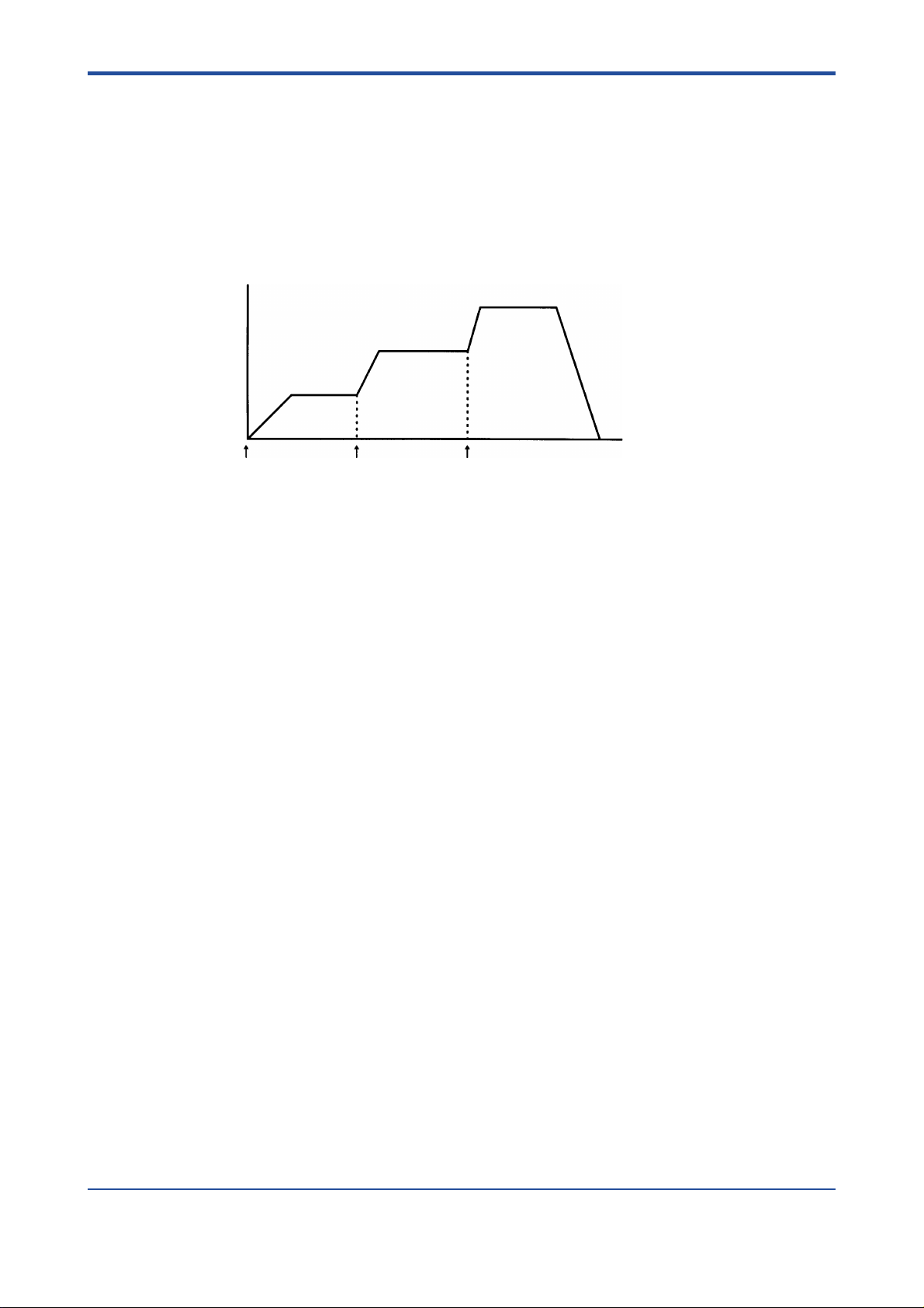
3.1 Positioning Operation
To initiate the positioning operation:
- first write the target velocity, target position, acceleration time, deceleration time and
other necessary parameters from the CPU module, and then
- change the state of the output relay defined as “Start Operation Command” from OFF
to ON.
When the positioning operation is complete, the input relay defined as “End of Positioning”
changes to the ON state. The trace of the acceleration/deceleration curve is trapezoidal,
where the acceleration/deceleration times are set separately.
3-2
Figure 3.1 Velocities and Acceleration/Deceleration Times in Trapezoidal and Trigonometric Drives
Figure 3.2 Comparison of Theoretical and Actual Behaviors of a Motor in Position Control
Figure 3.3 Acceleration/Deceleration Times Where Starting Velocity Is Set
IM 34M6H57-01E 2nd Edition : July, 2001-00
Page 24

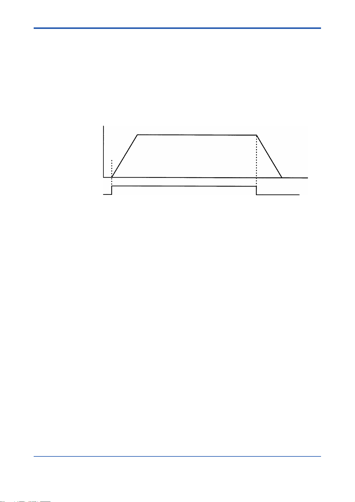
3.2 Change in Target P osition during P ositioning
To change the target position using the module:
- first write the parameters necessary for another positioning operation, and then
- change the state of the output rela y defined as “Request to Change Target Position”
from OFF to ON while the positioning operation is in progress.
The speed of rotation can also be changed at the same time you change the target position. The module is also able to change the target position when the direction in which the
motor rotates changes. (In that application, the module quickly slo ws down the motor to a
complete stop and enters the positioning operation where it searches for a new target
position.)
3-3
Velocity
Start
command
Time
Request to change
target position
Case Where Direction of Rotation
Does Not Change
Figure 3.4 Behaviors When the Target Position Is Changed
Velocity
Start
command
Request to change
target position
Case Where Direction of Rotation
Changes
Time
F0304.EPS
IM 34M6H57-01E 2nd Edition : July, 2001-00
Page 25
3.3 Change in V elocity during P ositioning
To change the velocity using the module, you must:
- first write the new target v elocity and other necessary parameters, and then
- change the state of the output rela y defined as “Request to Change Velocity” from
OFF to ON
while the positioning operation is in progress:
Velocity
3-4
Startup
Request to
change velocity
Figure 3.5 Behaviors When the Velocity Is Changed
Request to
change velocity
Time
F0305.EPS
IM 34M6H57-01E 2nd Edition : July, 2001-00
Page 26

3.4 V elocity Control
To initiate the velocity-control operation:
- first write the v elocity setpoint (a value with the min us sign if rotating the motor in the
negative direction), acceleration time, deceleration time and other necessary parameters from the CPU module, and then
- change the state of the output rela y defined as “Start Operation Command” from OFF
to ON.
The velocity-control operation continues until the output rela y defined as “Request to
Decelerate and Stop” or “Request to Stop Immediately” is turned on.
The trace of the acceleration/deceleration curve is trapezoidal, where the acceleration/
deceleration times are set separately.
3-5
IM 34M6H57-01E 2nd Edition : July, 2001-00
Page 27

3.5 Change in V elocity during V elocity Contr ol
To change the velocity using the module you must:
- first write the new target v elocity, and then
- change the state of the output rela y defined as “Request to Change Velocity” from
OFF to ON
while the velocity-control operation is in progress.
The change-in-velocity operation does not allow y ou to change the velocity in such a
manner that the direction in which the motor rotates changes. To change the direction, you
must first decelerate and stop the motor and then initiate the velocity-control operation after
setting a new target velocity.
Velocity
3-6
Startup
Request to
change velocity
Figure 3.6 V elocity Contr ol and Change-in-V elocity Operation
Request to
change velocity
Request to
change velocity
Time
Request to
decelerate and stop
F0306.EPS
IM 34M6H57-01E 2nd Edition : July, 2001-00
Page 28

3.6 Velocity-to-Position Control Mode Switching
The module switches to position control while it is in the velocity-control operation and
enters the positioning operation where the position at which the switch was made is set as
“0.” This action takes place while velocity-control operation is in progress and requires you
to:
- first write the target velocity, target position, acceleration time, deceleration time and
other necessary parameters from the CPU module, and then
- change the control mode from velocity control to position control.
The trace of the acceleration/deceleration curve is trapezoidal, where the acceleration/
deceleration times are set separately.
In addition to the normal switching (where switching takes place immediately after the given
command is executed), you can set such a switching mode in which the module waits for
an external trigger before it switches to position control. To switch to position control after
detecting a Z-phase input signal, specify the polarity of the Z-phase, as well as the frequency of Z-phase pulse counting.
Case where no Z-phase pulse counting is specified
Velocity
3-7
Target position (travel)
Startup
Case where Z-phase pulse counting is specified (twice during the rise time)
Velocity
Target position (travel)
Startup
Request to switch to
position control
Z-phase
signal
Figure 3.7 Behaviors When Switching from Velocity Control to Position Control
Time
Time
F0307.EPS
IM 34M6H57-01E 2nd Edition : July, 2001-00
Page 29
3.7 Jog Stepping
To carry out jog stepping:
- first write the target velocity, acceleration time, deceleration time and other necessary
parameters from the CPU module, and then
- change the state of the output relay defined as “Positive-direction Jog Stepping” or
“Negative-direction Jog Stepping” from OFF to ON.
To quit the jog-stepping operation, change the ON-state output relay to an OFF state.
Velocity
Start
Positive-direction
jog stepping
3-8
End
Time
F0308.EPS
Figure 3.8 Jog-stepping Operation (Positive Direction)
IM 34M6H57-01E 2nd Edition : July, 2001-00
Page 30

3.8 Emergency-stop Input
The positioning module has one emergency-stop input common to the uniaxial and biaxial
models. The input is designed f or e xclusive use as a type-b contact input. Be SURE to wire
the input when using the module. If the input is left open, the module does not operate at
all. You can read the state of the emergency-stop input like you read the states of other
contact inputs.
3-9
IM 34M6H57-01E 2nd Edition : July, 2001-00
Page 31

3.9 Contact Inputs
The positioning module has five external contact inputs defined as “POSITIVE-DIRECTION
LIMIT,” “NEGA TIVE-DIRECTION LIMIT, ” “ORIGIN,” “NEAR-ORIGIN” (e xternal trigger) and
“READY,” separately for both the uniaxial and biaxial models.
You can read the state of each contact input using an application program. In addition, you
can set the polarity of each contact input separately .
3-10
IM 34M6H57-01E 2nd Edition : July, 2001-00
Page 32

3.10 Z-phase Encoder Input
For the improv ed repeatability of origin searches, you can use the Z-phase encoder input.
You can read the state of the encoder input like you read the states of the contact inputs.
Likewise, y ou can set the polarity of the encoder input like you set the polarities of the
contact inputs.
3-11
IM 34M6H57-01E 2nd Edition : July, 2001-00
Page 33

3.11 Origin-search Operation
To start an origin search:
- first write the direction of the search, the search v elocity, the type of operation when an
external contact input is detected (origin-search mode), the direction of the edge for
detecting the Z-phase, and other necessary parameters, and then
- change the state of the output rela y defined as “Origin Search” from OFF to ON.
If the positioning module detects a change in the state of a preset external contact input
after the start of an origin-search operation, the module either stops the motor or checks
the Z-phase, depending on the setting of the contact input. When checking the Z-phase ,
the module detects the preset Z-phase pulse count and stops the motor immediately,
defining the position where the motor has stopped as the origin. F or this reason, if a servo
motor is used, the position where the motor actually stops is off from where the origin was
detected by as much as a distance equivalent to the offset pulse count (diff erence between
the pulse counts of a momentary command position and a current motor position) given
during an origin-search operation.
There is an application in which an origin search is carried out at two different speeds or a
change is made to the direction of rotation while checking for an e xternal contact input
during an origin search. In that case, split the origin search process into se ver al cycles
while varying parameters for each cycle, and do the searches separately. This strategy
enables you to customize y our origin-search operation to conduct searches using your
desired search patterns.
3-12
CAUTION
An offset in the origin due to an offset pulse count becomes greater as the velocity of origin
search becomes higher.
IM 34M6H57-01E 2nd Edition : July, 2001-00
Page 34

3.12 Linear-interpolated Operation
To carry out a linear-interpolated operation:
- first write the target v elocity, target position, acceleration time, deceleration time and
other necessary parameters for each axis from the CPU module, and then
- change the state of the output rela y defined as “Start Operation Command” from OFF
to ON for both axes sim ultaneously.
When the positioning operation for each axis is complete, the input rela y defined as “End of
Positioning” for each axis changes to the ON state.
In this operation, set the same acceleration and deceleration times for both ax es that are
brought into linear-interpolated operation. Calculate and set the ratio between the target
velocities of the two ax es so it equals the ratio between their respectiv e trav els .
3-13
Velocity
X-axis travel
Y-axis travel
Acceleration time Deceleration time
Figure 3.9 Multiaxial Linear-interpolated Operation (Example of Biaxial Application)
X-axis speed setpoint
Y-axis speed setpoint
Time
Y-axis
Y-axis travel
X-axis travel
X-axis
F0309.EPS
IM 34M6H57-01E 2nd Edition : July, 2001-00
Page 35

3.13 On-Route Operation
If you initiate another positioning operation while the current positioning operation is in
progress, the positioning module begins the new operation before the current operation
ends. The module therefore carries out a combination of these two operations until the
current operation ends. This mode of positioning operation is referred to as an on-route
operation. The interval at which the two operations overlap is called the on-route interval.
Using the on-route operation, you can continue your position finding toward the new target
position without stopping at the target position set for the current positioning operation. It is
also possible to define a mode of on-route operation where the direction of rotation may be
changed.
• Normal positioning operation
X-axis velocity
3-14
Startup Startup
• On-route operation
On-route
X-axis velocity
Startup Startup Startup
• Example of on-route operation in biaxial linear-interpolated operation
Y-axis
interval
On-route
interval
Time
Time
X-axis
Figure 3.10 Normal Position-finding Operation and On-Route Operation
F0310.EPS
IM 34M6H57-01E 2nd Edition : July, 2001-00
Page 36

3.14 Arc-interpolated Operation
The biaxial arc-interpolated operation can be implemented by converting a positioning
command from the CPU module into a trigonometric function within the positioning module.
To bring the positioning module into arc-interpolated operation:
- first define the center of the X-Y plane , radius, starting angle, angular tra vel and other
necessary parameters from the CPU module, and then
- change the state of the output rela y defined as “Start Operation Command” from OFF
to ON.
Y-axis
Angular travel (270°)
Y-axis radius
3-15
Path for arc interpolation
Y-axis center
Starting positionTarget position
X-axis center
Figure 3.11 Arc-interpolated Operation
Zero-angle direction
Starting angle
(-45° [or 315°])
X-axis radius
X-axis
F0311.EPS
IM 34M6H57-01E 2nd Edition : July, 2001-00
Page 37

Blank Page
Page 38

4. Parameters
4.1 List of Parameters
Among the parameters listed in Figures 4.2 through 4.6, the ones with two data position
numbers are two-word data. The data with the smaller numbers are low-order words, and
those with the larger numbers are high-order words. Data position numbers are specified
for each word. The WRITE and READ instructions used for accessing from a sequence
program must be on word-basis. Long-word based instructions cause inappropriate access.
You should also use word-based instructions when you access from BASIC programs.
Data whose setting units are [(1/65536) pulses/ms], [(1/65536) degrees], or [(1/65536)
degrees/ms] (
bits) and 1 decimal part-word (16 bits). The data with the smaller numbers are low-order
words, and those with the larger numbers are high-order words.
Fixed-point data
The digits in the integer part of the binary data are sequentially defined as 1, 2, 4 ... , and
the digits in the decimal part are defined as 1/2, 1/4, 1/8, and so forth. If both the integer
part and the decimal part consist of 16 bits, the least significant bit is 1/65536, which means
that it is a 32 bit (long-word) datum whose setting unit is 1/65536. Negative numbers are
expressed as complements of 2 like ordinary binary data.
1 in Tables 4.2 through 4.6) are fixed point data with 1 integer part-word (16
*
4-1
Tabl e 4. 1
Bit
Value
31 (MSB)
Sign bit
30
16384
High-order word Low-order word
. . .
. . .
17216115
1/2141/4
. . .
. . .
1
1/32768
0 (LSB)
1/65536
T0401.EPS
[Example of fixed point data]
When setting 123.45 [pulses/ms] (=123450 [pulses/sec]),
123.45x65536 = 8090419.2 [(1/65536) pulses/ms]
Thus, we should set 8090419 as a long-word data. The high-order word of this data is 123
since 8090419 / 65536 = 123. The low-order word is the remainder, i.e., 29491.
IM 34M6H57-01E 2nd Edition : July, 2001-00
Page 39

4-2
(Reference)
An example of sequence programs which convert data in [pulses/s] into data to used for
setting a positioning module
Let D0001 (long-word data) be the original data (pulses/s).
(1) Divide D0001 by 1000 (long-word division) and put the result into D0011. In this case,
since the maximum value of D0001 is 249750 (249.75 kpps) and it is positive, the
maximum value of the result is 249 and thus the high-order word (D0012) is always 0.
The low-order word of the result of the division (D0011) is the high-order word (the
integer part which is 16 bits long) of the value [(1/65536) pulses/ms] to be calculated.
The remainder is put into D0013 (the low-order word) and D0014 (the high-order
word). Since the maximum value of the remainder is 999 because the divisor is 1000,
the high-order word of the remainder (D0014) is always 0.
(2) Then, multiply the remainder by 65536 and divide it again by 1000. A useful trick here
is this: the remainder in D0013 and D0012 is 0; thus, if we treat D0012 as long-word
data, its value is already the result of multiplication of the remainder by 65536. (D0012
as lower-order word, D0013 as high-order word.) Therefore, in order to divide the
result of multiplication of the remainder by 65536 by 1000, all we have to do is divide
D0012 by 1000 (long-word division). Put the result of this division into D0021.
D0012 (long word) is 999*65536 at a maximum, and it is divided by 1000 is 65470 at
maximum and high-order word (D0022) and always becomes 0. Thus D0021 is the
value [(1/65536) pulse/ms] of low-order word (the decimal part of 16 bits) and the
remainder will be discarded as truncation.
(3) Now, we are going to combine the operation results D0011 and D0021 calculated in
(1) and (2) above into a long word data [(1/65536) pulses/ms]. To do this, we only have
to do long-word division twice and transfer the resulting high-order word and low-order
word individually to the area (D0032, D0031). D0011-D0014 and D0021-D0024 are
the work areas.
(1) Long-word division
D0011 D0001 / 1000
Operation results
D0014
0
=
D0013
Remainder
D0012
0
D0011
High-order of
[(1/65536) pulses/ms]
(2) Long-word division
D0021 = D0012 / 1000
Operation results
D0024
0
D0023
Remainder
D0022
0
D0021
Low-order of
[(1/65536) pulses/ms]
IM 34M6H57-01E 2nd Edition : July, 2001-00
Page 40

MOV D0011 D0032
MOV D0021 D0031
Operation results
D0032
High-order of [(1/65536)]
pulses/ms
in the case of 123450 [pulses/s]
*
D0031
Low-order of
[(1/65536) pulses/ms]
(1) D0011 = 123450/1000 (long-word division)
4-3
D0014
0
D0013
450
29491200 (450*65536)
D0012
0
D0011
123
(2) D0021 = 29491200/1000 (long word division)
D0024
0
D0023
200
D0022
0
D0021
29491
The high-order word of the [1/65536) pulses/ms] data is 123, and the low-order word is
29491.
IM 34M6H57-01E 2nd Edition : July, 2001-00
Page 41

4.1.1 Registered parameters
Entry parameters are usually set only once after turning the power on. You can set them by
writing from the CPU module and then executing the Set Parameter command.
Table 4.2 Registered parameters
4-4
Data Position Number
Axis 1 Axis 2
030/031 230/231 Positive-direction Limit Value 0 to 8388608 [pulses]
032/033 232/233 Negative-direction Limit Value -8388608 to 0 [pulses]
034/035 234/234 Velocity Limit Value 0 to 16367616 [1/65536) pulses/ms]
036 236 Rotation Direction
037 237 Pulse Output Mode
038 238 Contact Input Polarity Specified for each point as a bit
Parameter Name Setup Range
0: CW pulse in positive direction
1: CW pulse in negative direction
0: Pulse and direction signal
1: CW pulse and CCW pulse
4.1.2 Operation Parameters
Operation parameters are referred to when starting operations like position control or
velocity control. These parameters do not have initial values. It is necessary to write all the
required parameters when executing a command.
(1) In Position Control Mode (excluding Arc Interpolation)
Table 4.3 Position Control Mode Operation Parameters (excluding arc interpolation)
1
*
T0402.EPS
Data Position Number
Axis 1 Axis 2
001 to 008 001 to 008
009/010 209/210
011/012 211/212 Target velocity -16367616 to 16367616 [(1/65536) pulses/ms]
013 213 Acceleration Time 0 to 32767 [ms]
014 214 Deceleration Time 0 to 32767 [ms]
015 215 (not used)
016/017 216/217 Target Position
018 218 Interpolation Mode 0
019 219 Control Mode Switching Parameter Set by a bit pattern
(not used)
Initial velocity 0 to 16367616 [(1/65536) pulses/ms]
Parameter Name Setup Range
-8388608 to 8388608 [pulses]
1
*
1
*
T0403.EPS
IM 34M6H57-01E 2nd Edition : July, 2001-00
Page 42

(2) In Velocity Control Mode
Table 4.4 Velocity Control Mode Operation Parameters
4-5
Data Position Number
Axis 1 Axis 2
001 to 008 201 to 208
009/010 209/210 Initial Velocity 0 to 16367616 [(1/65536) pulses/ms]
011/012 211/212 Target Velocity -16367616 to 16367616 [(1/65536) pulses/ms]
013 213 Acceleration Time 0 to 32767 [ms]
014 214 Deceleration Time 0 to 32767 [ms]
015 215 Time Interval for Velocity Change Time 0 to 32767 [ms]
016 to 018 216 to 218
019 219
(not used)
(not used)
Control Mode Switching Parameter Set by a bit pattern
Parameter Name Setup Range
1
*
(3) In Position Control Mode (Arc Interpolation)
Table 4.5 Position Control Mode (Arc Interpolation) Operation Parameters
Data Position Number
Axis 1 Axis 2
001/002 201/202 Center Position -8388608 to 8388608 [pulses]
003/004 203/204 Radius 1 to 8388608 [pulses]
005/006 205/206 Starting Angle
007/008 207/208 Angular Travel
009/010 209/210 Starting Angular Velocity
011/012 211/212 Angular Velocity Setpoint
013 213 Acceleration Time 0 to 32767 [ms]
014 214 Deceleration Time 0 to 32767 [ms]
015 215 (not used)
016/017 216/217 Target Position -8388608 to 8388608 [pulses]
018 218 Interpolation Mode 1: X Axis 2: Y Axis
2: If the set range is beyond the limits specified, the module will not operate correctly.
*
Parameter Name Setup Range
-23592960 to 23592960 [(1/65536) degrees]
(-360 to 360 [degrees])
-2123366400 to 2123366400 [(1/65536) degrees]
(-90 to 90 [rotation])
0 to 23592960 [(1/65536) degrees/ms]
360 [degrees])
0 to 23592960 [(1/65536) degrees/ms]
[degrees])
*1*
*1*
1
*
T0404.EPS
1
*
1
*
2 ( up to
2 ( to 360
T0405.EPS
IM 34M6H57-01E 2nd Edition : July, 2001-00
Page 43

4.1.3 Common Parameters
Common parameters are referred to when starting special operations like backlash correction or origin-search. These parameters do not have initial values. It is necessary to write all
the required parameters when executing the commands.
Table 4.6
4-6
Data Position Number
Axis 1 Axis 2
020 220 Origin-Search Mode Set by a bit pattern
021 221 Origin-Search Direction 0: negative direction 1: positive direction
022 222 Z-phase Edge Selection 0: OFF to ON edge 1: ON to OFF edge
023 223 Z-phase Pulse Count 0 to 32767 [times]
024/025 224/225 Z-phase Search Range 0 to 8388608 [pulses]
026/027 226/227 Backlash Correction Value -8388608 to 8388608 [pulses]
028/029 228/229 Backlash Correction velocity 0 to 16367616 [(1/65536) pulses/ms]
Parameter Name Setup Range
*
1
T0406.EPS
IM 34M6H57-01E 2nd Edition : July, 2001-00
Page 44

4-7
4.2 List of Required Parameters for each Command
To execute a command for the positioning module from the CPU module, it is necessary to
write all the required parameters in advance.
The list below shows the required parameters for each command.
The Set Parameter command is not included in this list because it changes all the entry
parameters.
● Mandatory parameters.
: Parameters which are required or not depending on the values of other parameters.
- : Non-required parameters (have no effect on the operation of the commands).
Table 4.7 List of Required Parameters for Each Command
Command name (output relay name)
→ velocity control)
Parameter name
→ position control)
Center position
Radius
Starting angle
Angular travel
Initial (angular velocity)
Target velocity (angular velocity)
Acceleration time
Deceleration time
Time interval for velocity change
Target position
Interpolation mode
Control mode switching para.
Origin position search mode
Origin position search direction
Z-phase edge selection
Z-phase pulse count number
Z-phase search area
Backlash correction value
Backlash correction speed
Start operation command
(in position control made)
Start operation command
(in velocity control mode)
Start operation command
(in arc-interpolated operation)
-
-
-
-
-
-
-
-
●
●
●
●
●●
●
●
-
-
●
-
-
●
--
-
-
-
-
-
-
-
-
-
-
-
-
-
-
-
-
●
-
●
-
●
●
-
-
●
●
-
●
-
●
-
-
-
●
-
●
-
●
-
-
-
-
-
-
-
-
-
-
-
-
-
-
Request to switch control mode
(position control
Request to switch control mode
(velocity control
Start origin search
Backlash correction
Request to change target pos.
Request to change velocity
(during position control operat.)
Request to change velocity
(during velocity control oper.)
Request to change velocity
during arc interpolation
Positive-direction Jog stepping
Negative-direction Jog stepping
Write current position
Request to decelerate & stop
Request to stop Immediately
Error reset
-
-
-
-
----
-
-
●
●
●
●
●
●●
●
●
-
-
-
●
-
-
●
-
-
●
●
-
-
-
--
-
-
-
-
-
-
-
-
-
●
-
●●●
-
-
●
-
-
-
●
-
-
-
-
-
-
-
-
-
-
--
-
-
-
●
-
●
--
-
-
--
--
●-●
-
-
-
●
-
-
---
-
-
-
-
-
-
-
-
--
-
-
-
-
-
-
-
-
-
-
-
-
-
-
-
-
-
-
-
-
--
-
-
-
--
-
---
-
--
-
--
-
●
●
-
-
-
●
-
-
-
●
-
-
-
-
-
-
-
-
-
-
-
-
-
-
-
-
-
-
-
-
-
-
-
-
-
-
-
-
-
-
-
-
-
T0407.EPS
IM 34M6H57-01E 2nd Edition : July, 2001-00
Page 45

4.3 Description of Parameters
4.3.1 Entry parameters
When the power is switched on, all entry parameters are cleared. Please set all entry
parameters using the Set Parameter command in a application program. When the parameter value set is invalid, data error results. When this happens, execute Error Reset and
execute the Set Parameter command again with the valid values.
Table 4.8 Entry parameters
Parameter Type: Setting Content: Data Range: Remarks:
Positive-direction
Limit Value
Negativedirection Limit
Value
Velocity Limit
Value
Rotation
Direction
Control Output
Mode
Sets the operation
limit position in
positive/negative
direction as the
number of pulses
from the origin.
Sets the limit of
the target velocity
Sets the relation
between the
positive and
negative signs of
the position and
the direction of the
pulse output from
the CPU module
Sets the mode of
the position
command pulse
output.
0 to 8388608 [pulses]
-8388608 to 0 [pulses]
0 to 16367616 [(1/65536) pulse/ms] If you start the system after
0: CW pulse in the positive direction
1: CW pulse in the negative direction
0: pulse-and-direction signal 1: CW pulse and
CCW pulse. In the pulse-and-direction signal
mode, pulse output A is the pulse and B is the
polarity signal. In the CW pulse and CCW pulse
mode, pulse output A is the CCW pulse and B is
the CW pulse.
If the origin search is not
executed, then the position at
the moment when the main
switch was turned on is
defined as the origin. When
these limits are exceeded, an
error results. If you start the
system after setting a target
position beyond this range,
an error results and the motor
does not start. The detection
of the limit values in both
directions is not performed
during origin-search or in
velocity control mode. (Error
does not occur.)
setting a velocity beyond this
range, an error results and
the motor does not start.
During an operation (e.g. arcinterpolated operation), if this
value is exceeded, an error
results.
The direction of the operation
(positive or negative) is
defined by the direction of the
position set from the CPU
module.
4-8
Contact Input
Polarity
Defines the logic
of the external
contact input and
the Z-phase input.
Specified for each point as a bit. "0" indicates
an "a" contact "a" and "1" indicates a "b"
contact.
15- -543210
x----XXXXXX
Origin Input
Near-origin Input
(External Trigger Input
Positive-direction limit Input
Negative-direction limit Input
Ready Input
Z-phase Encoder Input
a" contact input is an input
which is effective when signal
input exists, and "b" contact
input is an input which is
effective without signal input.
For example, a "limit input of
'b' contact" detects a limit
when there is no signal input,
but does not detect a limit
when signal input exists.
T0408.EPS
IM 34M6H57-01E 2nd Edition : July, 2001-00
Page 46

4.3.2 Operation Parameters
Table 4.9 Operation Parameters
Parameter Type: Setting Cantact: Data Range: Remarks:
Center Position
Radius Refer to the section for arc-
Starting Angle Refer to the section for arc-
Angular Travel Refer to the section for arc-
Starting Velocity
Starting Angular
Velocity
Target velocity Sets operation velocity in
Setting Angular
Velocity
Acceleration Time Sets the time it takes to reach the
Deceleration Time Set the time from target velocity
Time Interval for
velocity change
Target Position Set the target position for the
Interpolation Mode Be sure to set [0] for usual
Control Mode
Switching
parameter
Refer to the section for arcinterpolation
interpolation
interpolation
interpolation
This is the starting velocity of the
operation at the start of the
positioning operation and the
velocity just before stopping at
end of positioning. When using, a
pulse motor and accelerating
from velocity [0], at the low
velocity portion during
acceleration, resonance may
occur resulting in detachment.
(same as in deceleration). Set a
velocity faster than the resonance
point to prevent this from
happening. When using a servo
motor, it is normally set to [0].
Position Control and Velocity
Control mode. For arc
interpolation, refer to the section
on arc-interpolation.
target velocity from the starting
Velocity at operation startup
to Decelerate and Stop.
Set the acceleration
(deceleration) time from the
preset speed to the new velocity
during execution of the Change
Velocity command in Velocity
Control mode.
positioning operation. For arcinterpolation, refer to the section
on arc-interpolation.
positioning operation in position
control mode, For arc
interpolation, refer to the section
on arc-interpolation.
This is referred during execution
of Switch Control Mode
command. It sets the mode or
conditions for switching.
-8388608 to 8388608 [pulses]
1 to 8388608 [pulses]
-23592960 to 23592960 [(1/65536) degrees]
(-360 to 360 [degrees])
-2123366400 to 2123366400
[(1/65536) degrees] (-90 to 90 [rotation])
0 to 16367616 [(1/65536) pulses/ms]
0 to 23592960 [(1/65536) degrees/ms]
(up to 360 [degrees])*1
0to 16367616 [(1/65536) pulses/ms]
(in position control mode)
-16367616 to 16367616 [(1/65536) pulses/ms]
(in velocity control mode)
0 to 23592960 [(1/65536) degrees/ms]
(to 360 [degrees])*1
0 to 32767 [ms] In target point change and
0 to 32767 [ms]
0 to 32767 [ms]
-8388708 to 8388608 [pulses]
0: normal operation
1: Arc Interpolation X axis
2: Arc Interpolation Y axis
Specified by bit pattern
15 down to 10
x-xx
• Waiting for external contract input
(during Velocity Control to Position
Control Switching)
• waiting for Z-phase encoder input
(during Velocity Control to Position
Control switching)
When using this parameter,
parameter values that are too
large may cause deregulation
at startup or stop because of
impact. Therefore, take care.
Setting starting velocity is
also possible in arcinterpolation. However, when
reversing the operation
direction in this case, each
axis decelerates/accelerates
slowly to velocity [0], so it is
less effective at preventing
deregulation of the pulse
motor.
If the value of the target velocity
(angular velocity) specified is
smaller than the starting
velocity (angular velocity), the
operation is performed with
target velocity [0]. Normally, set
a value larger than the starting
velocity (angular velocity).
velocity change, it has
different meaning. Refer to
the explanations of each
command for details
Set [0] for switching to
velocity control mode and
either [$8000], [$8001],
[$8002], or [$8003] for
switching to positioning
control depending on the
conditions for switching.
4-9
• 0: Position Control to Velocity Control
switching
1: Velocity Control to Position Control
switching
T0409.EPS
IM 34M6H57-01E 2nd Edition : July, 2001-00
Page 47

■ About Arc Interpolation
At positioning startup, when you specify the Arc Interpolation X Axis or the Arc Interpolation
Y Axis in "Interpolation Mode", arc-interpolated positioning is performed. The positioning
module generates the following command position and operates in the following way.
Note:
The X axis and Y axis which perform the arc interpolation are not related to axis 1 and axis
2 of the positioning module. It is not necessary that the X axis and Y axis are in the same
positioning module.
The trajectory of the arc interpolation is generated by:
X axis Center Position + Radius × COS (Starting Angle + Angular Velocity Set point × Time)
Y axis Center Position + Radius × SIN (Starting Angle + Angular Velocity Set point × Time)
When (Angular velocity Setpoint × time) is equal to Angular Travel, the operation ends. If
Acceleration Time and Deceleration Time are both 0, the actual path is the same as the one
defined by the above formulas. Otherwise, as Angular Velocity increases / decreases with
time, the term (Angular Speed Setpoint
the basic idea is the same. In the case of arc interpolation, Acceleration Time is the time
interval in which the angular velocity changes from 0 to Angular Velocity Setpoint when
starting, Deceleration Time is the time interval in which the angular velocity changes from
Angular Velocity Setpoint to 0 when stopping.
4-10
×
time) is not the same as that in the formulas. But
The arc interpolation operation is realized by setting the parameters to X axis and Y axis
independently , and then starting them simultaneously. So, it is necessary to specify the
same value on both axes for Starting Angle, Angular Travel, Angular Velocity Setpoint,
Acceleration Time and Deceleration Time.
Here “Angle” is defined in the X-Y plane with the positive part of the X axis as 0 degree ,
and to increase in the counterclockwise direction. For example, the positive part of the Y
axis is 90 degrees, and the negative part of the X axis is 180 degrees.
In the following, we will explain the case for X axis. For Y axis, change COS to SIN.
When the system starts, in the positioning module, the starting position of the arc interpolation operation can be computed using the above formulae with Time set as 0, that is,
Center Position + Radius
This position must coincide with the current position of the axis when starting the system.
(Set the parameters so that the above condition is satisfied.) If not, the positioning module
outputs the difference pulses at once when starting the system. If the velocity of the output
pulses exceeds the velocity limit value, an error occurs.
The position where the arc interpolation operation ends is calculated with the following
formula:
Center Position + Radius
Thus, this position must coincide with Target Position. (Set the parameters so that the
above condition is satisfied.) If not, the positioning module outputs the difference pulses at
once when the arc-interpolation operation ends. If the Velocity of the output pulses exceeds
the velocity limit value, an error occurs.
×
COS (Starting Angle).
×
COS (Starting Angle + Angular Travel)
Note: When starting the operation, the difference pulses at the end of the operation are all
output within 2 ms.
IM 34M6H57-01E 2nd Edition : July, 2001-00
Page 48

Y-axis
Angular travel (270°)
Y-axis radius
Y-axis center
X-axis center position
Figure 4.1 Arc-Interpolated Operation
4-11
Path for arc interpolation
Zero-angle direction
Starting angle
(-45° [315°])
Starting positionTarget position
X-axis radius
X-axis
F0401.EPS
CAUTION
The X axis and Y axis move independently also when performing arc interpolation. So
when an error occurs at one axis, the other axis continues moving. If it is necessary to stop
the other axis, stop the motor by applying the immediate stop command to the moving axis
after detecting the error with an application program (and checking the input relay labeled
“Error Notification”).
IM 34M6H57-01E 2nd Edition : July, 2001-00
Page 49

4.3.3 Common Parameters
Table 4.10 Common Parameters
Parameter Type Data Range Setting Contents Remarks
Origin-search Mode Sets the motion of the motor for each
contact input after detecting the edges
of each contact input during originsearch using bit patterns. For details,
refer to "3.11, "Origin-search
Operation."
Origin-search Direction
Sets the motor rotation direction
during origin-search.
Z-phase Edge Selection Sets the polarity of the Z-phase input
when detecting Z-phase during originsearch or during speed to position
control switching.
Z-phase Pulse Count Sets which nth Z-phase is effective
when detecting Z-phase during originsearch or during speed to position
control switching.
Z-phase Search Range Error occurs if the Z-phase cannot be
detected after operating the number
of pulses which was set by this
parameter when detecting Z-phase
during origin-search or during speed
to position control switch.
Backlash Correction Value
This is used to correct the backlash
between the motor shaft and the
Backlash Correction
moving parts (looseness of gears,
etc.).
Set using bit pattern
of the data.
0: negative direction
1: positive direction
0: OFF to ON edge
1: ON to OFF edge
0 to 32767 [times]
0 to 8388608 [pulses] This parameter is used to
prevent continued operation
of the motor when Z-phase
cannot be detected
because of Z-phase signal
disconnection, etc. Usually,
this is set close to the
period of the Z-phase.
-8388608 to 8388608
[pulses]
0 to 16367616
[(1/65536) pulses/ms]
When executing backlash
correction, outputs the
backlash correction value
pulse at the backlash
correction without changing
the current position status.
In this case, there is no
acceleration and
deceleration. Refer to
Figure 4.2, "Execution
Example of Backlash
Correction."
4-12
T0410.EPS
Velocity
Backlash correction
Execution
Startup
Backlash correction velocity
Backlash correction Value
Figure 4.2 Backlash Correction Execution Example
Startup
Time
F0402.EPS
IM 34M6H57-01E 2nd Edition : July, 2001-00
Page 50

4.4 Entry Parameters Setting Example
The following example shows the minimum setting of the entry parameters for controlling
the motor using the positioning module. The underlined values are set.
■ The motor used
Rated number of revolutions: 3000 rpm
Encoder pulse count: 8192 pulses/rotation
CAUTION
You can set and change the ratio of the command pulses and encoder pulses on the servo
driver side. In these cases, the parameters set in the positioning module must match the
setting of the servo driver. So calculate the values of the entry parameters after confirming
the setting of the servomotor.
■ Mechanism
4-13
Direct shaft drive using ball screws
Ball screw pitch: 5 mm/rot
Operation Range: -500 mm to +1000 mm (operates in the positive direction with the positive velocity command voltage)
Maximum speed: 6000 mm/min (100 mm/s)
Contact Input: Positive-direction limit (“b” contact), negative-direction limit (“b” contact),
origin (“a” contact), ready signal (“a”) contact. Others are not used.
■ Calculation of the entry parameters
- Positive-direction Limit Value
1000 [mm] 4 5 [mm/rot] 3 8192 [pulses/rot] =
- Negative-direction Limit Value
-500 [mm] 4 5 [mm/rot] 3 8192 [pulses/rot] =
- Speed Limit Value
100 [mm/sec] 4 5 [mm/rot] 3 8192 [pulses/rot] = 163840 [pulses/s]
163840 [pulses/s] 4 1000 3 65536 =
- Rotation Direction
1638400 [pulses]
-819200 [pulses]
10737418 [(1/65536) pulses/ms]
CW pulse and positive-direction operation,
- Control Output Mode
CW pulse / CCW pulse method,
- Contact Input Polarity
$000C
Positive-direction limit (“b”), negative-direction limit (“b”), origin (“a”), ready (“a”),
encoder Z-phase (“a”). Others are not used and set to “a” contact temporarily.
1
0
IM 34M6H57-01E 2nd Edition : July, 2001-00
Page 51

Blank Page
Page 52

5. Status
The status is the data where the CPU module is called up from the positioning module. The
positioning module is checked by this data and input rela ys .
5.1 List of Status
Status listed with 2 data position numbers are two-word data. The data with the smaller
number is the low-order word, and the one with the larger number is the high-order word.
Data position numbers are specified for each word. The READ instruction used f or accessing from a sequence program must be on a word basis. Long-word based instructions
cause inappropriate access.
You should also use word-based instructions when you access from BASIC programs.
5-1
Data whose setting unit is [(1/65536) pulses/ms] (
1 in Table 5.1) are fixed-point data with 1
*
word integer part (16 bits) and 1 word decimal part (16 bits). The data with the smaller
number is the low-order word, and the one with the larger number is the high-order word.
For fixed-point data, ref er to “List of P arameters .”
Reference:
To convert data in [(1/65536) pulses/ms] into one in [pulses/ms], multiply it by 1000 in long-
word operation and use the second and the third words as long-word data, ignoring the
lowest-order and highest-order words.
(Example)
Let D0001 a long-word data in [(1/65536) pulses/ms]. The operation is as f ollows:
D0011 = D0001
Operation Result:
D0014
0
T able 5.1 List of Status
D0013 D0012
Long-word data [pulses/sec]
*
1000
D0011
Truncated Portion
Data Position Number
Axis 1 Axis 2
039 239 Error Status See error codes when an error occurs.
040 240 Contact Input Status State of contact input
041/042 241/242 Current Position Status [pulses]
043/044 243/244 Current Velocity Status [(1/65536) pulses/ms]
045/046 245/246 Target Position Status [pulses]
047 247
048 248 Extended Status
Parameter Name Set Range
1
*
Remaining
Deceleration Time
Remaining time until the system reaches the target position
during positioning operation [ms]
Operation information including accelerating/decelerating/
overlapping/waiting for trigger/control mode, etc.
IM 34M6H57-01E 2nd Edition : July, 2001-00
T0501.EPS
Page 53

5-2
CAUTION
If two-word data are read from the CPU module, the timing differential betw een the CPU
module’s readout timing and the positioning module’s data update period may cause the
loss of simultaneity between high- and low-order words in two-word data.
If the two-word data are read from the sequence CPU, read those data twice using a READ
instruction to make the read data coincide, thus assuring the simultaneity of the high- and
low-order words in two-word data. For this purpose, if an HRD instruction is used, you
cannot attain data simultaneity.
If the data are read from a BASIC CPU, there will be a dela y in reading two-word data in
comparison with the data update period of the positioning module, so data simultaneity
cannot be assured.
IM 34M6H57-01E 2nd Edition : July, 2001-00
Page 54

5.2 Description of Status
● Error Status
Reads an error code when an error occurs. It is meaningless when the rela y defined as
“Error Notification” is OFF. F or details , refer to the list of error codes .
● Contact Input Status
Reads the state of the external contact input, the emergency stop input and the Z-phase
encoder input. The state of each contact is stored as 1 bit (0: OFF, 1: ON). When a contact
is specified as “a” contact, it is represented by “1” if the contact is open. When a contact is
specified as “b” contact, it is represented by “1” if the contact is closed. (Emergency stop
input is fixed as a “b” contact input.)
15~ ~ 6 5 4 3 2 1 0
------------------x x x x x x x
5-3
- Origin input
- Near-origin input (external trigger input)
- Positive direction input
- Negative direction input
- Ready input
- Encoder Z-phase input
- Emergency stop input
● Current P osition Status (Command P osition) [pulses]
Reads the current position. This is the current position of the output pulse of the positioning
module, so in the case of a servo motor , it is not the actual position of the motor .
● Current V elocity Status (Command P osition) [(1/65536) pulses/ms]
Reads the current velocity. This is the current v elocity of the output pulse of the positioning
module, so in the case of a servo motor, it is not the actual speed of the motor. Its value is
always z ero or positive regardless of the rotation direction of the motor .
● Target Position Status [pulses]
Reads the operation target position during a positioning operation. The target position set at
the start of the positioning is stored as the operation target position.
● Remaining Deceleration Time [ms]
Reads the time interval between the start of deceleration to stop at the target position and
end-of-positioning during positioning operation. Its v alue is “0” when the system is not
moving, and “-1” during acceleration or at a constant speed.
CAUTION
This status shows the time until the system stops at the target position. Theref ore, it cannot
read the remaining deceleration time when decelerating in a Decelerate-and-Stop command in velocity-control mode or during positioning operation. This status is used to chec k
the timing to start an on-route operation, etc.
IM 34M6H57-01E 2nd Edition : July, 2001-00
Page 55

● Extended Status
Reads the data expressing the operation states of the axes in bits . Each bit is set to “1”.
15~ ~7 6 5 4 3 2 1 0
x x x 0 0 0 0 0 x x x x x x x x
- Accelerating
- Moving at constant velocity
- Decelerating
- Accelerating in the latter operation in the
on-route interval
- Constant velocity in the latter operation in
the on-route interval
- Decelerating in the latter operation in the
on-route interval
- Decelerating during target position change
with direction Change
- Accelerating/decelerating during velocity
change
- Origin detected during origin search
(Rev. 4 or later)
- Waiting for control-mode switching
(waiting for velocity to position)
- In velocity-control mode
5-4
CAUTION
In some cases, the positioning module restricts the ex ecution of commands depending on
its state. (Ref er to the e xplanation of each command.) Then it is necessary to get the
detailed status of the positioning module with an application program. F or that purpose, use
this extended status. Usually, the data is separated into bits after reading.
IM 34M6H57-01E 2nd Edition : July, 2001-00
Page 56

6. List of Input/Output Relays
The positioning module has 32 input and output relays as the interface to the FA-M3 CPU
module. For details on the input/output relays, refer to “Module Access Method.”
CAUTION
In the F3NC11-0N module, absolutely do not set the output relays related to axis 2
(Y
ingless in this case.
6.1 Output Relays
Table 6.1 Positioning Operation Control Output Relay
49 to Y 64). The input relays for axis 2 (X 17 to X 32) are mean-
6-1
Output Relay Number
Axis 1 Axis 2
Y 33 Y 49 Start Operation Command
Y 34 Y 50 Switch Control Mode
Y 35 Y 51 Request to Decelerate and Stop
Y 36 Y 52 Request to Stop Immediately
Y 37 Y 53 Start Origin Search
Y 38 Y 54 Backlash Correction
Y 39 Y 55 Request to Change Target Position
Y 40 Y 56 Request to Change Velocity
Y 41 Y 57 Reserved
Y 42 Y 58 Positive-direction Jog-Stepping
Y 43 Y 59 Negative-direction Jog-Stepping
Y 44 Y 60 Write Current Position
Y 45 Y 61 Error Reset
Y 46 Y 62 Reserved
X 47 Y 63 Reserved
X 48 Y 64 Set Parameters
Note: Insert the FA-M3 slot number where this module is installed in .
Operation when ON
T0601.EPS
IM 34M6H57-01E 2nd Edition : July, 2001-00
Page 57

6.2 Input Relays
Table 6.2 Positioning Operation Control Input Relay
6-2
Output Relay Number
Axis 1 Axis 2
X 01 X 17 Start Operation Command ACK
X 02 X 18 Switch Control Mode ACK
X 03 X 19 Decelerate and Stop ACK
X 04 X 20 Stop Immediately ACK
X 05 X 21 End of Origin Search
X 06 X 22 Backlash Correction ACK
X 07 X 23 During Positive-direction Operation
X 08 X 24 During Negative-direction operation
X 09 X 25 Change Target Position ACK
X 10 X 26 Change Speed ACK
X 11 X 27 Write Current Position ACK
X 12 X 28 Error Notification
X 13 X 29 Reserved
X 14 X 30 Reserved
X 15 X 31 End-of-positioning
X 16 X 32 Set Parameters ACK
Note: Insert the FA-M3 slot number where this module is installed in .
Operation when ON
T0602.EPS
IM 34M6H57-01E 2nd Edition : July, 2001-00
Page 58

7. Accessing Modules
In the program examples shown in this chapter, the positioning module is installed in the
4th slot (slot #004) of the main unit; when only one axis is used in these examples, it will be
axis 1.
7.1 Accessing from Sequence CPU
The following are the instructions to access from the sequence CPU with the ladder sequence program. For details on each instruction, see the “Sequence CPU Instruction
Manual - - - Instructions” (publication number IM 34M6P12-03E).
Reading/Writing Parameters and Status
The instructions should be of the word unit. The long-word instructions cannot be used.
- Special Module Read instruction (READ instruction)
READ SL n1 D k
SL: Slot number where the module is installed
7-1
n1: First data position number for reading data
D: First device to store the read data
k: Number of data (in word unit) to be read
- Special Module Write instruction (WRITE instruction)
WRITE S SL n2 k
S: Device to store the write data
SL: Slot number where the module is installed
n2: First data position number for the write data
k: Number of data (in word unit) to be written
- Special Module High-Speed Read instruction (HRD instruction)
HRD SL n1 D k
SL: Slot number where the module is installed
n1: First data position number for reading data
D: First device to store the read data
k: Number of data (in word unit) to be read
- Special Module High-Speed Write instruction (HWR instruction)
HWR S SL n2 k
S: Device to store the write data
SL: Slot number where the module is installed
n2: First data position number for the write data
k: Number of data (in word unit) to be written
IM 34M6H57-01E 2nd Edition : July, 2001-00
Page 59

7.1.1 Reading the Module Status
This section explains how to read the status of the positioning module.
Items to Note:
- There is no special item to note here. The status of the positioning module can be read
at any time.
Program Example:
In this example below, all of the status is read at once with the READ command.
- List of major devices used
D0039 Error Status Read
D0040 Contact Input Status Read
D0041/D0042 Current Position Status Read
D0043/D0044 Current Velocity Status Read
D0045/D0046 Target Position Status Read
D0047 Remaining Decelerating Time Read
D0048 Extended Status Read
D0121/D0122 Current Velocity [pulses/second]
D0131 to D0134 (Operating Work Area)
I00001 to 100016 Bit Data of Contact Input
I00017 to 100032 Bit Data of Extended Status
7-2
F0701T.EPS
(0001)
(0002)
00001
(0003)
(0004)
(0005)
(0006)
Module status reading program
M0033
Figure 7.1 Module Status Reading Program
Status
10D0039394READ
I00001D0040MOV
I00017D0048MOV
1000D0043=D0131
D0121D0132MOV
expand contact input
expand extended input
charge current speed
pulses/sec
F0701.EPS
IM 34M6H57-01E 2nd Edition : July, 2001-00
Page 60

7.1.2 Setting Parameter s
This sets the entry parameters.
Items to Note:
- This command is accepted only if all the following conditions are satisfied: (1) not in
error status, (2) in End-of-P ositioning status, and (3) not e x ecuting other commands. If
these conditions are not satisfied, then the command will be ignored.
- When an error occurs with the Parameter-Setting command, run the Error Reset
command, and then the Parameter-Setting command again with proper data.
Procedures:
1) Write parameters on the positioning module with the WRITE instruction.
2) Set the Parameter-Setting output relay.
3) Reset Parameter-Setting output relay after confirming that Parameter Setting A CK
input relay is set. (If there is an y error in the parameters, the P arameter Setting A CK
input relay is not set, but Error Notification input rela y is set.)
4) Check that Parameter Setting ACK is reset.
7-3
Program Example:
In this example, parameters are set in the data register in adv ance. All entry parameters are
written at once with the WRITE instruction.
- List of major devices used
D0001/D0002 Positive Direction Limit Value
D0003/D0004 Negative Direction Limit Value
D0005/D0006 Velocity Limit Value
D0007 Rotation Direction
D0008 Pulse Output Mode
D0009 Contact Input Polarity
Y00448 Parameter Setting (Output Relay)
X00416 Parameter Setting ACK (Input Relay)
I00099 Command Execution Prohibit Condition (set in another part)
I00101 Request to Execute command
I00102 Request to Execute command (Differentiate Up)
I00103 Waiting for ACK
I00104 Executing Command
I00105 Forced Release of Parameter Setting
F0702T.EPS
IM 34M6H57-01E 2nd Edition : July, 2001-00
Page 61

7-4
(0010)
(0011)
00012
(0009)
00014
(0010)
(0011)
(0012)
(0013)
00024
(0014)
(0015)
00031
Parameter Setting Program
I00101
I00102 I00099
I00103 Y00448 X00416
I00105
I00104 I00103 X00416
Figure 7.2 Parameter Setting Program
I00102DIFU
D0001WRITE 9304
Y00448SET
I00103SET
I00104SET
Y00448RST
I00103RST
I00104RST
F0702.EPS
Figure 7.3 Parameter-Setting Program Time Chart
IM 34M6H57-01E 2nd Edition : July, 2001-00
Page 62
7.1.3 Error Reset
This resets the error status of the positioning module.
Items to Note:
The positioning module ignores any commands other than the Error-Reset command in
error status (i.e. status where the Error-Notification input relay is set). So be sure to execute
the Error-Reset command in error status.
Procedures:
1) Set the Error-Reset output relay.
2) Check that the Error-Notification relay is reset. Then reset the Error-Reset output relay.
Program example:
This example assumes that the Error-Reset operation is done manually. All output relays of
the positioning module are reset at the time of the Error-Reset operation. The error code is
preserved until the completion of Error Reset.
7-5
- List of major devices used
X00412 Error Notification (Input Relay)
Y00445 Error Reset (Output Relay)
I00111 Request to Reset Error (Manually Operated Signal)
I00112 Request to Reset Error (Differentiate Up)
I00113 Request to Reset Error (Differentiate Down)
D0201 Error Code Storage Device
(0016)
(0017)
00035
(0018)
(0019)
00040
(0020)
(0021)
(0022)
00048
Error Reset Program
I00111
I00112 X00412
I00113
4READ
39
MOV
F0704T.EPS
I00112DIFU
I00113DIFD
1D0201
Y004330
Y00445SET
Y00445RST
Figure 7.4 Error Reset Program
F0704.EPS
IM 34M6H57-01E 2nd Edition : July, 2001-00
Page 63

Figure 7.5 Error Reset Program Time Chart
7-6
IM 34M6H57-01E 2nd Edition : July, 2001-00
Page 64

7.1.4 Jog Stepping
When the Positive (Negative)-direction Jog-Stepping output relay is ON, the motor will be
rotated in the positive or negative direction.
Items to Note:
- This command is accepted only if all of the following conditions are satisfied: (1) not in
error status, (2) in End-of-Positioning status, (3) in position control mode, and (4) not
executing other command. Otherwise, it is ignored.
- During jog stepping, you can stop the motor with the Stop Immediately command, but
not with the Decelerate-and-Stop command. Terminate jog stepping first when the
“decelerate and stop” is desired.
Procedures:
1) Write required parameters of the Jog-Stepping command on the positioning module.
2) When the Positive-direction (Negative-direction) Jog-Stepping output relay is set, the
motor rotates according to the parameters, the Operating-in Positive-direction (Negative-direction) input relay is set, and the End-of-Positioning input relay is reset.
7-7
3) Reset the Positive-direction (Negative-direction) Jog Stepping output relay. The motor
will be decelerated and stopped according to the parameters set at the start of the jogstepping. Then the End-of-Positioning input relay is set.
Program Example:
In this example, the jog stepping starts with the Request for Jog Stepping, and ends with
the release of the request. Jog stepping mode is reset automatically if any error occurs
during jog stepping. This example shows only the positive-direction case. Required parameters are set in advance in the data registers.
- List of major devices used
D0201/D0202 Starting Speed
D0203/D0204 Setpoint Speed
D0205 Acceleration Time
D0206 Deceleration Time
Y00442 Positive-direction Jog Stepping (Output Relay)
X00415 End-of-positioning (Input Relay)
X00412 Error Notification (Input Relay)
I00099 Command Execution Prohibit Condition (set in another part)
I00121 Jog Stepping Request
I00122 Jog Stepping Request (Differentiate Up)
I00123 Jog Stepping Request (Differentiate Down)
I00124 Executing Positive-direction Jog Stepping
F0706T.EPS
IM 34M6H57-01E 2nd Edition : July, 2001-00
Page 65

7-8
(0023)
(0024)
00050
(0025)
(0026)
00055
(0027)
(0028)
(0029)
00063
(0030)
(0031)
Jog Stepping Program
I00121
I00122 I00099
I00124 I00123 Y00442
Y00442 X00415
X00412
Figure 7.6 Jog Stepping Program
I00122DIFU
I00123DIFD
D201WRITE
4
SET69Y00442
I00124SET
Y00442RST
I00124RST
F0706.EPS
Figure 7.7 Jog Stepping Program Time Chart
IM 34M6H57-01E 2nd Edition : July, 2001-00
Page 66

7.1.5 Origin-Search
This executes origin-search. There are four external contact inputs related to origin-search.
The origin-search mode specifies the action when each rising and falling edge of these four
inputs (eight in total) are detected during the origin-search using bit patterns. (2 bits for
each edge, so 16 bits in total.)
As in the example below, the condition of the search includes: The direction of the originsearch is negative, (1) Stop immediately when the rising edge of the Negative-Direction
Limit is detected, (2) Decelerate and stop when the rising edge of the Origin input is detected, and (3) Shift to Z phase search when the falling edge of the Origin-Search is detected. The Origin Search mode is set in the following way:
15 ~ ~0
1100000000001001 (=$C009)
(1) (3) (2)
(1)
Negative direction
Negative direction
7-9
Z-phase detected, end origin search
(3) (2)
Positive
direction
Limit input
Origin input
F0708.EPS
Figure 7.8 Example of Origin-search Operation
IM 34M6H57-01E 2nd Edition : July, 2001-00
Page 67

[Origin-search Mode in detail:]
The mode is set in bits according to the list below. There are four ways of setting using two
bits for the rising and falling edges of one external contact input.
15~ ~0
xxxxxxxxxxxxxxxx
||||||||||||||||
||||||||||||||00--||||||||||||||01--||||||||||||||10--||||||||||||||11--||||||||||||00----||||||||||||01----||||||||||||10----||||||||||||11----||||||||||00------||||||||||01------||||||||||10------||||||||||11------||||||||00--------||||||||01--------||||||||10--------||||||||11--------||||||00----------||||||01----------||||||10----------||||||11----------||||00------------||||01------------||||10------------||||11------------||00--------------||01--------------||10--------------||11--------------00----------------01----------------10----------------11-----------------
Fall in origin input, ignore
Fall in origin input, Z-phase search
Fall in origin input, decelerate and stop
Fall in origin input, stop immediately
Rise in origin input, ignore
Rise in origin input, Z-phase search
Rise in origin input, decelerate and stop
Rise in origin input, stop immediately
Fall in near-origin input (external trigger input), Ignore
Fall in near-origin input (external trigger input), Z-phase search
Fall in near-origin input (external trigger input), decelerate and stop
Fall in near-origin input (external trigger input), stop immediately
Rise in near-origin input (external trigger input), ignore
Rise in near-origin input (external trigger input), Z-phase search
Rise in near-origin input (external trigger input), decelerate and stop
Rise in near-origin input (external trigger input), stop immediately
Fall in positive-direction limit input, ignore
Fall in positive-direction limit input, Z-phase search
Fall in positive-direction limit input, decelerate and stop
Fall in positive-direction limit input, stop immediately
Rise in positive-direction limit input, ignore (Error during positive-direction operation)
Rise in positive-direction limit input, Z-phase search
Rise in positive-direction limit input, decelerate and stop
Rise in positive-direction limit input, stop immediately
Fall in negative-direction limit input, ignore
Fall in negative-direction limit input, Z-phase search
Fall in negative-direction limit input, stop immediately
Fall in negative-direction limit input, stop immediately
Rise in negative-direction limit input, ignore (Error during negative-direction operation)
Rise in negative-direction limit input, Z-phase search
Rise in negative-direction limit input, decelerate and stop
Rise in negative-direction limit input, stop immediately
7-10
F0708B.EPS
IM 34M6H57-01E 2nd Edition : July, 2001-00
Page 68

Items to Note:
- This command is accepted only if all of the following conditions are satisfied: (1) not in
- The origin-search ends when a specified external contact input is detected and the
- In the following cases, an error occurs and the search is automatically stopped:
- If you want to change the setup values according to the status of the external contact
- Even after shifting to the Z-phase search, if an external contact input with Decelerate-
7-11
error status, (2) in End-of-Positioning status, (3) in position control mode, and (4) not
executing other command. Otherwise, it is ignored.
search stopped. Change the parameters and re-execute the origin-search after it ends
if you want to continue the search in another direction or with a different velocity.
- The limit input of the origin-search direction is set as ignored but the limit input is
detected.
- After shifting to the Z-phase search, the limit input of the origin-search direction is
detected (causes errors regardless of the setting).
- After shifting to the Z-phase search, Z-phase cannot be detected within the Z-
phase search range.
input at the beginning of the origin search, read the state with the Contact Input Status
and then execute the origin-search.
and-Stop / Stop Immediately setup is detected, the origin-search is stopped following
the setup. (This is different from the origin-search operation of F3NC5
.)
Procedures:
- In versions earlier than Rev. 3, even during the origin-search operation, when the
operation is performed beyond the “Positive-Direction Limit Value” and the “Negative-
Direction Limit Value,” an error occurs and the search is stopped. When performing
origin-search, adjust these parameter values to avoid errors.
1) Write parameters required by the Origin-Search command on the positioning module.
2) The motor rotates following the parameters when the output relay defined as “Start
Origin-search” is set. The motor continues to rotate until a specified external contact
input is detected.
3) When the Z-pulse is detected for the specified number of times after shifting to Zphase search (if the Z-phase Pulse Count Number is specified as ‘’0", then without
shifting to Z-phase), the current position is considered as “Position 0” and the operation is stopped immediately. The input relays defined as “End of Positioning” and “End-
of-Origin Search” are set. The End-of-Origin Search is reset if the Start-Origin Search
is reset. However, if the Start-Origin Search is reset before the End-of-Origin Search
is set, then the End-of-Origin Search is not set. (The input relay labeled “End of Originsearch” is set when there is no shift to Z-phase search and the operation is stopped
due to the Stop Immediately or Decelerate-and-Stop setting, or when the operation is
stopped with the Decelerate-and-Stop command. If the operation is stopped with the
Immediate Stop command, the input relay labeled “End of Origin search” is not set.)
(For reference: For F3NC5
the Immediate-Stop command, the input relay defined as “End-of-Origin search” is not
set.)
, if you stop with the Decelerate-and-Stop command or
- Bit 13 of the Extended Status (End-of-Origin-Search during the origin-search operation) is set only when the operation is stopped after shifting to Z-phase search and
detecting the Z-phase (if the Z-phase count is specified as ‘’0", then without shifting to
Z-phase). This bit is reset when the origin-search starts. It is “0” when the power is
turned on. (This function is available in versions later than Rev. 4.)
IM 34M6H57-01E 2nd Edition : July, 2001-00
Page 69

Program example:
This program starts the origin search using the Request-to-Start Origin Search and stops it
using the specified external contact input.
If any error is detected during the search, the search mode is automatically reset.
The following program also occupies area for non-required parameters because all the
parameters are written at once.
All required parameters are set in advance in the data register.
- List of major devices used
D0301/D0302 Initial Velocity
D0303/D0304 Target Velocity
D0305 Acceleration Time
D0306 Deceleration Time
D0307~D0311 (unnecessary area)
D0312 Origin-search Mode
D0313 Origin-search Direction
D0314 Z-phase Edge Selection
D0315 Z-phase Pulse Count
D0316/D0317 Z-phase Search Range
Y00437 Start Origin-search (Output Relay)
X00405 End of Origin-search (Input Relay)
X00412 Error Notification (Input Relay)
I00099 Command Execution Prohibit Condition (set in another part)
I00131 Request for Origin-search
I00132 Request for Origin-search (Differentiate Up)
I00133 Origin-search Operation
I00134 Executing Origin-search
7-12
F0709T.EPS
(0032)
(0034)
00074
(0035)
00076
(0036)
(0037)
(0038)
(0039)
00086
(0040)
(0041)
00095
Origin-search Program
I00131
I00132 I00099
I00133 Y00437 X00405
X00412
I00134 I00133 X00405
Figure 7.9 Origin-search Program
D0301WRITE 4
IM 34M6H57-01E 2nd Edition : July, 2001-00
SET
I00132DIFU
179
Y00437SET
I00133
I 00134SET
Y00437RST
I00133RST
I00134RST
F0709.EPS
Page 70

Figure 7.10 Origin-search Program Time Chart
7-13
IM 34M6H57-01E 2nd Edition : July, 2001-00
Page 71

7.1.6 Write Current Position
This changes the current position of the axis during End-of-Positioning in position control
mode.
Items to Note:
- This command is accepted only if all of the following conditions are satisfied: (1) there
is no error; (2) it is in End-of-Positioning mode; and (3) no other commands are not
being executed. Otherwise, it is ignored.
- The change position should fall in the range from the positive-direction limit to the
negative-direction limit. An error occurs when requesting to change beyond the limits
of the range.
- It is impossible to write the current position during the positioning operation or in
speed control mode. In these cases, the command is ignored.
Procedures:
1) Write the desired position after the change in the Target Position parameter.
2) Set the output relay defined as “Request to Write Current Position.”
7-14
3) Reset the relay defined as “Request to Write Current Position” after confirming that the
input relay defined as “Current Position Write ACK” is set. If there is a parameter error,
the input relay defined as “Error Notification” is set and the Current Position Write ACK
is not set.
Program Example:
This is an example to write the current position. All required parameters are set in advance
in the data register.
- List of major devices used
D0401/D0402 Target Position (Current Position to change)
Y00444 Request to Write Current Position (Output Relay)
X00411 Current Position Write ACK (Input Relay)
I00099 Command Execution Prohibit Condition (set in another part)
I00141 Request to Write Current Position
I00142 Request to Write Current Position (Differentiate Up)
I00143 Waiting for ACK
I00144 Executing Command
F0711T.EPS
IM 34M6H57-01E 2nd Edition : July, 2001-00
Page 72

7-15
(0042)
(0043)
00099
(0044)
00101
(0045)
(0046)
(0047)
(0048)
00111
(0049)
(0050)
00120
Current Position Writing Program
I00141
I00142 I00099
I00143 Y00444 X00411
X00412
I00144 I00143 X00411
Figure 7.11 Current Position Writing Program
D0401WRITE 4
SET
I00142DIFU
216
Y00444SET
I00143
I00144SET
Y00444RST
I00143RST
I00144RST
F0711.EPS
Figure 7.12 Current Position Writing Program Time Chart
IM 34M6H57-01E 2nd Edition : July, 2001-00
Page 73

7.1.7 Position Control Mode Operation
(1) Start Operation command (Positioning Operation)
When the start-operation command is executed during End-of-Positioning, the normal
positioning operation starts. When it is executed during positioning operation, it executes
two overlapping positioning operations (called on-route operation) start. The latter case will
be explained in the section on on-route operation.
Items to Note:
- This command is accepted only if all of the following conditions are satisfied: (1) there
is no error; (2) no other commands are being executed; (3) it is not during an origin
search; and (4) no jog stepping is occurring. Otherwise, it is ignored. Further, in
normal positioning, there are 2 additional conditions: (5) it is in the End-of-Positioning
status, (6) it is in the position control mode. (If (5) and (6) are not satisfied, an error
occurs.)
- If an invalid value is set in an operation parameter, an error occurs and the motor does
not move.
7-16
Procedure:
1) Write the required parameters in the positioning module.
2) Set the output relay defined as “Request to Start Operation.”
3) After confirming that the Start-Operation Command ACK input relay is set, reset the
Start-Operation relay. The motor starts according to timing when the Start-Operation
ACK is set. (If there is a parameter error, Start-Operation ACK input relay is not set
and Error-Notification input relay is set.)
4) The End-of-Positioning input relay of the positioning module is set when the pulse
output by the positioning module reaches the target position. In general cases using a
servomotor, there is some time lag between the stopping of the pulse output and the
stopping of the motor after reaching the target position. Be careful about this time lag.
IM 34M6H57-01E 2nd Edition : July, 2001-00
Page 74

Program Example:
This is an example of a simple-positioning operation. All required parameters are set in
advance in the data register.
- List of major devices used
D0501/D0502 Initial Velocity
D0503/D0504 Target Velocity
D0505 Acceleration Time
D0506 Deceleration Time
D0507 (unnecessary area)
D0508/D0509 Target Position
D0510 Interpolation Mode
Y00433 Start-Operation command (Output Relay)
X00401 Start-Operation command ACK (Input Relay)
X00415 End of Positioning (Input Relay)
I00099 Command-Execution-Prohibit Condition (set in another part)
I00201 Request-to-Start Operation Command
I00202 Request-to-Start Operation Command (Differentiate Up)
I00203 Waiting for Command ACK
I00204 Positioning In Progress
7-17
F0713T.EPS
(0051)
(0052)
00124
(0053)
00126
(0054)
(0055)
(0056)
(0057)
00136
(0058)
(0059)
00145
Positioning Operation Program
I00201
I00202 I00099
I00203 Y00433 X00401
X00412
I00204 I00203 X00415
D0501WRITE 4
SET
I00202DIFU
109
Y00433SET
I00203
I00204SET
Y00433RST
I00203RST
I00204RST
Figure 7.13 Positioning Operation Program
F0713.EPS
IM 34M6H57-01E 2nd Edition : July, 2001-00
Page 75

Figure 7.14 Positioning Operation Program Time Chart
7-18
IM 34M6H57-01E 2nd Edition : July, 2001-00
Page 76

(2) Change Target Position
When the target position is changed during positioning operation, immediately. a positioning operation at the new target position starts. You can change the target velocity when
changing the target position. In this case, the acceleration/deceleration between the velocities before and after the change is expressed by the slope calculated from the new target
velocity and the acceleration time/deceleration time.
Items to Note:
- This command is accepted only if all of the following conditions are satisfied: (1) there
is no error; (2) no other commands are being executed; (3) there is no interval in the
on-route operation; (4) it is not during arc-interpolated operation; (5) it is not during an
origin search; (6) no jog-stepping is occurring; and (7) it is in position-control mode.
Otherwise, it is ignored. If an invalid value is set in an operation parameter, an error
occurs and the motor stops immediately.
Procedure:
1) Write the required parameters in the positioning module.
2) Set the output relay defined as “Request to Change Target-Position.”
7-19
3) Reset the relay defined as “Request to Change Target-Position” after confirming that
the input relay defined as “Target-Position Change ACK” is set. The motor starts the
Change Target-Position operation when the Change Target-Position ACK relay is set.
(If there is a parameter error, the input relay defined as “Target-Position Change ACK”
is not set and the input relay defined as “Error Notification” is set.)
Program Example:
This is an example to change the target position during a positioning operation.
The following program occupies area for non-required parameters because all the parameters are written at once.
All required parameters are set in advance in the data register.
- List of major devices used
D0601/D0602 Initial Velocity
D0603/D0604 Target Velocity
D0605 Acceleration Time
D0606 Deceleration Time
D0607 (unnecessary area)
D0608/D0609 Target Position
Y00439 Request to Change Target Position (Output Relay)
X00409 Target-Position Change ACK (Input Relay)
I00099 Command Execution Prohibit Condition (set in another part)
I00211 Request to Start Target-Position Change
I00212 Request to Start Target-Position Change (Differentiate Up)
I00213 Waiting for Command ACK
I00214 Executing Command
F0715T.EPS
IM 34M6H57-01E 2nd Edition : July, 2001-00
Page 77

7-20
(0060)
(0062)
00149
(0063)
00151
(0064)
(0065)
(0066)
(0067)
00161
(0068)
(0069)
00170
Change Target-Position Program
I00211
I00212DIFU
I00212 I00099
D0601WRITE 4
Y00439SET
SET99I00213
I00214SET
I00213 Y00439 X00409
Y00439RST
X00412
I00213RST
I00214 I00213 X00409
I00214RST
Figure 7.15 Change Target-Position Program
Figure 7.16 Change Target-Position Program Time Chart
F0715.EPS
IM 34M6H57-01E 2nd Edition : July, 2001-00
Page 78

Application Function:
- Change Target Position with a change in operating direction
If the new position has already been passed at the time of executing Change Target
Position, Decelerate-and-Stop is performed immediately and the positioning operation
with the new target position starts. (If the new position has not yet been passed at the
time of executing Change Target Position, but will be passed even if the deceleration is
started immediately, the same steps occur).
When Change Target-Position with Change Operation-Direction is executed, do not
execute another Change Target-Position command or Change Velocity command in
the first deceleration operation. Otherwise, the operation cannot be guaranteed. You
can confirm the status by reading the extended status.
- Change Target Position during End of Positioning
You can execute the Change Target Position command during End of Positioning
(when motor is not moving). In this case, the operation is the same as the normal
positioning operation.
7-21
IM 34M6H57-01E 2nd Edition : July, 2001-00
Page 79

(3) Change Velocity
If the “Change Velocity” is executed during positioning operation, velocity changes are
made immediately. The slope corresponding to the acceleration/deceleration between the
velocities before and after the change and the deceleration when stopping at the target
position is the slope calculated from the parameters at the start of the positioning operation.
Items to Note:
- This command is accepted only if all of the following conditions are satisfied: (1) there
is no error; (2) no other commands are being executed; (3) there is no interval in the
on-route operation; (4) it is not during an origin-search; and (5) no jog-stepping is
occurring. Otherwise, it is ignored.
- If an invalid value is set in an operation parameter, an error occurs and the motor
stops immediately.
Procedures:
1) Write the required parameters in the positioning module.
2) Set the output relay defined as “Request to Change Velocity.”
7-22
3) Reset the relay defined as “Request to Change Velocity” after confirming that the input
relay defined as “Change velocity ACK” is set. The motor starts the change velocity
operation when Change velocity ACK is set. (If there is a parameter error, the input
relay defined as “Change Input ACK” is not set and the input relay defined as “Error
Notification” is set.)
Program Example:
This is an example to change velocity during a positioning operation. All required parameters are set in advance in the data register.
- List of major devices used
D0701/D0702 Target velocity
Y00440 Request to Change velocity (Output Relay)
X00410 Change velocity ACK (Input Relay)
I00099 Command Execution Prohibit Condition (set in another part)
I00221 Request to Start Change velocity
I00222 Request to Start Change velocity (Differentiate Up)
I00223 Waiting for Command ACK
I00224 Executing Command
F0717T.EPS
IM 34M6H57-01E 2nd Edition : July, 2001-00
Page 80

7-23
(0070)
(0071)
00174
(0072)
00176
(0073)
(0074)
(0075)
(0076)
00186
(0077)
(0078)
00195
Change Velocity (during Positioning Operation) Program
I00221
I00222 I00099
D0701WRITE 4
I00223 Y00440 X00410
X00412
I00224 I00223 X00410
Figure 7.17 Change Velocity (during Positioning Operation) Program
SET
I00222DIFU
211
Y00440SET
I00223
I00224SET
Y00440RST
I00223RST
I00224RST
F0717.EPS
Figure 7.18 Change Velocity (during Positioning Operation) Program Time Chart
IM 34M6H57-01E 2nd Edition : July, 2001-00
Page 81

7.1.8 Velocity Control Mode Operation
The positive- and negative-direction limit values are ignored in velocity control mode.
(1) Switch Position to Velocity Control mode
The positioning module is in position control mode when power is turned on. To perform
speed control operation, it is necessary to switch the Position to Velocity Control mode.
Items to Note:
- This command is accepted only if all of the following conditions are satisfied: (1) there
is no error; (2) no other command is being executed; (3) there is no interval in the onroute operation; (4) it is not during an arc-interpolated operation; (5) it is not during
origin search; and (6) no jog stepping is occurring. Otherwise, it is ignored.
- When switching position control to velocity control, no parameters, other than the
Switch Control Mode parameter is referred to. The control is switched to velocity
control while maintaining the same velocity.
Procedures:
7-24
1) Write “0” (switch to speed control) as the value of the Switch Control Mode parameter
in the positioning module.
2) Set the output relay defined as “Request to Switch Control Mode.”
3) Reset the relay defined as “Request to Switch Control Mode” after confirming that the
input relay defined as “Switch Control Mode ACK” is set. The motor is switched to
velocity control mode while maintaining the same velocity.
Program Example:
This is an example of switching position control to velocity control.
- List of major devices used
Y00438 Request to Switch Control Mode (Output Relay)
X00406 Switch Control Mode ACK (Input Relay)
I00099 Command Execution Prohibit Condition (set in another part)
I00301 Request to Switch Control Mode
I00302 Request to Switch Control Mode (Differentiate Up)
I00303 Waiting for Command ACK
I00304 Executing Command
F0719T.EPS
IM 34M6H57-01E 2nd Edition : July, 2001-00
Page 82

7-25
(0079)
(0080)
00199
(0081)
00201
(0082)
(0083)
(0084)
(0085)
00211
(0086)
(0087)
00220
Position to Velocity Control Switching Program
I00301
I00302 I00099
I00303 Y00434 X00402
X00412
I00304 I00303 X00402
Figure 7.19 Position to Velocity Control Switching Program
0WRITE 4
SET
I00302DIFU
119
Y00434SET
I00303
I00304SET
Y00434RST
I00303RST
I00304RST
F0719.EPS
Figure 7.20 Position to Velocity Control Switching Program Time Chart
IM 34M6H57-01E 2nd Edition : July, 2001-00
Page 83

(2) Start Operation Command (for velocity Control)
Velocity control starts when you execute the Start-Operation command in velocity control
mode. This command starts the operation only. To stop a motor in velocity control operation,
the Decelerate-and-Stop command or the Stop-Immediately command must be executed.
Items to Note:
- This command is accepted only if all of the following conditions are satisfied: (1) there
is no error; (2) no other command is being executed; (3) it is not during an origin
search; and (4) no jog stepping is occurring. Otherwise, it is ignored. When starting
during velocity control, the additional required conditions are (5) it is in the End-ofPositioning state; (6) it is in the velocity-control mode. (If items (5) and (6) above are
not satisfied, an error occurs)
- If an invalid value is set in an operation parameter, an error occurs and the motor
stops immediately.
- In the velocity control mode, you must write a positive or negative value as the target
velocity for the positive or negative direction operation.
Procedures:
7-26
1) Write required parameters on the positioning module
2) Set the output relay defined as “Start Operation Command.”
3) Reset the relay defined as “Start Operation Command” after confirming that the input
relay defined as “Start Operation Command ACK” is set. The motor starts the opera-
tion when Start Operation Command ACK is set. (If there is a parameter error, the
input relay defined as “Start Operation Command ACK” is not set and the input relay
defined as “Error Notification” is set.)
Program Example:
This is an example of starting with the velocity control operation. All required parameters
are set in advance in the data register.
- List of major devices used
D0801/D0802 Initial Velocity
D0803/D0804 Target Velocity
D0805 Acceleration Time
D0806 Deceleration Time
Y00433 Start-Operation Command (Output Relay)
X00401 Start-Operation Command ACK (Input Relay)
X00415 End of Positioning (Input Relay)
I00099 Command Execution Prohibit Condition (set in another part)
I00311 Request to Start Operation
I00312 Request to Start Control Mode (Differentiate Up)
I00313 Waiting-for-Command ACK
I00314 Executing Command
F0721T.EPS
IM 34M6H57-01E 2nd Edition : July, 2001-00
Page 84

7-27
(0088)
(0089)
00224
(0091)
00226
(0092)
(0093)
(0094)
(0095)
00236
(0096)
(0097)
00245
Velocity-Control starting program
I00311
I00312 I00099
I00313 Y00433 X00401
X00412
I00314 I00313 X00401
Figure 7.21 Velocity-Control starting program
I00312DIFU
D0801WRITE 4
Y00433SET
SET69I00313
I00314SET
Y00433RST
I00313RST
I00314RST
F0721.EPS
Figure 7.22 Velocity-Control Program Time Chart
IM 34M6H57-01E 2nd Edition : July, 2001-00
Page 85

(3) Change Velocity
When the Change-Velocity command is executed in velocity control mode, a change in
velocity is then made. The acceleration or deceleration from a change in velocity is performed according to the time interval for velocity change.
When stopping a motor with a Decelerate-and-Stop command after changing velocity, the
system follows the deceleration mode / deceleration time set at the execution of the
Change-velocity command.
Items to Note:
- This command is accepted only if all of the following conditions are satisfied: (1) there
is no error; (2) no other command is being executed; (3) there is no interval in the onroute operation; (4) it is not during an origin-search; and (5) no jog stepping is occurring. Otherwise, it is ignored. In the position control mode, the operation will be different.
- If an invalid value is set in an operation parameter, an error occurs and the motor
stops immediately.
- In velocity-control mode, you must write a positive (negative) value as the target
velocity for the positive- or negative-direction operation.
7-28
- You cannot change the operating direction with the Change-Velocity command. (You
cannot change to a negative velocity setpoint during a positive-direction operation, nor
change to a positive velocity setpoint during a negative-direction operation.) To
change the operating direction in velocity control mode, you must stop the motor with
the Decelerate-and-Stop command and then restart the motor in the opposite direction.
Procedure:
1) Write the required parameters on the positioning module
2) Set the output relay defined as “Request to Change Velocity.”
3) Reset the relay defined as “Request to Change Velocity “ after confirming that the
input relay defined as “Change-Velocity ACK” is set. The motor starts the operation
when the Change-Velocity ACK is set. (If there is a parameter error, the input relay
defined as “Change-Velocity ACK” is not set and the input relay defined as “Error
Notification” is set.)
Program Example:
This is an example of changing the velocity. All required parameters are set in advance in
the data register.
The following program also occupies area for non-required parameters because all the
parameters are written at once.
IM 34M6H57-01E 2nd Edition : July, 2001-00
Page 86

- List of major devices used
D0901/D0902 Target Velocity
D0903 to D0904 (unnecessary area)
D0905 Time Interval for Velocity Change
Y00440 Request to Velocity (Output Relay)
X00410 Change-Velocity ACK (Input Relay)
I00321 Request to Change Velocity
I00322 Request to Change Velocity (Differentiate Up)
I00323 Waiting-for-Command ACK
I00324 Executing Command
7-29
F0723T.EPS
(0098)
(0099)
00249
(0100)
00251
(0101)
(0102)
(0103)
(0104)
00261
(0105)
(0106)
00270
Velocity-Change(during velocity Control) Program
I00321
I00322 I00099
D0901WRITE 4
I00323 Y00440 X00410
X00412
I00324 I00323 X00410
Figure 7.23 Velocity-Change(during velocity Control) Program
SET
I00322DIFU
511
Y00440SET
I00323
I00324SET
Y00440RST
I00323RST
I00324RST
F0723.EPS
Figure 7.24 Velocity-Change (during Velocity Control) Program Time Chart
IM 34M6H57-01E 2nd Edition : July, 2001-00
Page 87

7.1.9 Switch Velocity to Position Control
Switches to position control in velocity control mode. Positioning operation starts from
scratch where the velocity to position control is switched, according the preset parameters.
When changing velocity with mode change, the acceleration / deceleration between the
velocities before and after the change is expressed by the slope calculated from the new
target velocity and the acceleration time/deceleration time.
When stopping after completing the positioning operation, the deceleration time is that set
at the switch-control mode execution.
Items to Note:
- This command is accepted only if all of the following conditions are satisfied: (1) there
is no error; (2) no other command is being executed; (3) there is no interval in the onroute operation; (4) it is not during an arc-interpolated operation; (5) it is not during an
origin search; and (6) no jog-stepping is occurring. Otherwise, it is ignored. When
executed in position-control mode, the input relay defined as “Switch Control-Mode
ACK” is set, but the state of the positioning module is not changed.
- If an invalid value is set in an operation parameter, an error occurs and the motor
stops immediately.
7-30
- When switching velocity to position control, the positioning is performed with the target
velocity and target position effective at the time of the switch. Therefore, when you
execute switch control while stopping in Velocity Control-Mode at a target position
other than “0”, the positioning operation starts.
Procedure:
1) Write the required parameters on the positioning module.
2) Set the output relay defined as “Request to Switch Control Mode.”
3) Reset the relay defined as “Request to Switch Control-Mode” after confirming that the
input relay defined as “Switch Control-Mode ACK” is set. When “Switch Control-Mode
ACK” is set, the mode is switched to position control mode and the positioning operation starts. (If there is a parameter error, the input relay defined as “Switch ControlMode ACK” is not set and the input defined as defined as “Error Notification” is set.)
Program Example:
This is an example of switching velocity to position-control. All required parameters are set
in advance in the data register.
The following program also occupies area for non-required parameters because all the
parameters are written at once.
IM 34M6H57-01E 2nd Edition : July, 2001-00
Page 88

- List of major devices used
D1001/D1002 Initial Velocity
D1003/D1004 Target Velocity
D1005 Acceleration Time
D1006 Deceleration Time
D1007 (unnecessary area)
D1008/D1009 Target Position
Y00438 Request to Switch Control Mode (Output Relay)
X00406 Switch control-Mode ACK (Input Relay)
X00415 End-of-positioning (Input Relay)
I00099 Command Execution Prohibit Condition (set in another part)
I00331 Request to Switch Control Mode
I00332 Request to Switch Control Mode (Differentiate Up)
I00333 Waiting-for-Command ACK
I00334 Executing Command
7-31
F0725T.EPS
(0107)
(0108)
00274
(0157)
00276
(0110)
(0111)
(0112)
(0113)
(0114)
00288
(0115)
(0116)
00297
Velocity to Position-Control Switching Program
I00331
I00332 I00099
I00333 Y00438 X00406
X00412
I00334 I00333 X00406
Figure 7.25 Velocity to Position-Control Switching Program
I00332DIFU
D1001WRITE 4
$8000WRITE 4 119
Y00438SET
SET99I00333
I00334SET
Y00438RST
I00333RST
I00334RST
F0725.EPS
IM 34M6H57-01E 2nd Edition : July, 2001-00
Page 89

Figure 7.26 Velocity to Position Control Switching Program Time Chart
7-32
Application Function:
- External trigger input wait and Z-phase wait functions
If you set “$8001” as the value of the Switch Control-Mode parameter, the mode is not
changed to velocity control until the external trigger input is “ON”. This function is used,
for example, to execute switch control mode after the arrival of an external synchronizing signal. Likewise, if you set “$8002”, the mode is switched to position control after
the Z-phase specified by Z-Phase Edge Selection common parameter is detected as
many times as specified by the Z-phase Pulse Count. If you set “$8003”, the mode is
switched after detecting “ON” of the external trigger input followed by a Z-phase
detection.
- Switching velocity to position control with operation direction change
If the operation direction in speed control is different from the direction of the target
position after switching, Decelerate-and-Stop is performed immediately and the
positioning operation with the new target position starts. (If the operation direction
does not change, but the new target position will be passed if the deceleration is
started immediately, the same step occurs.)
IM 34M6H57-01E 2nd Edition : July, 2001-00
Page 90

7.1.10 Request to Decelerate and Stop
Decelerates and stops the operating motor during the positioning operation, velocity-control
operation, etc. The slope of deceleration during decelerate-and-stop is determined from the
setup values at the start. (When a command that sets the deceleration time is again executed, then the setup values at that moment are used for the above purpose.)
Items to Note:
- This command is accepted only if all of the following conditions are satisfied: (1) there
is no error; (2) no other command is being executed; (3) there is no interval in the onroute operation, and (4) no jog-stepping is occurring. Otherwise, it is ignored.
- If it is necessary to stop in the on-route interval, execute the Stop-Immediately command.
- You cannot execute the Decelerate-and-Stop command during the jog-stepping
operation. Terminate jog-stepping, if necessary.
- The positioning module also accepts the Decelerate-and-Stop command during the
end-of-positioning. (The corresponding ACK is set.)
- Do not execute the start of a new positioning operation or the Change Target-Position
command when decelerating in the Decelerate-and-Stop command. Otherwise, the
operation cannot be guaranteed.
7-33
Procedure:
1) Set the output relay defined as “Request to Decelerate and Stop.”
2) Reset the relay defined as “Request to Decelerate and Stop” after confirming that the
input relay defined as “Decelerate-and-Stop ACK” is set. The motor starts decelerating
when Decelerate-and-Stop ACK is set.
3) The input relay defined as “End of Positioning” is set when the motor stops.
Program Example:
This is an example of Request to Decelerate and Stop.
- Major devices used:
Y00435 Request to Decelerate and Stop (Output Relay)
X00403 Decelerate-and-Stop ACK (Input Relay)
X00415 End of Positioning (Input Relay)
I00099 Command Execution Prohibit Condition (set in another part)
I00401 Request to Decelerate and Stop
I00402 Request to Decelerate and Stop (Differentiate Up)
I00403 Waiting-for-Command ACK
I00404 Waiting to Decelerate and Stop
F0727T.EPS
IM 34M6H57-01E 2nd Edition : July, 2001-00
Page 91

7-34
(0117)
(0119)
00301
(0120)
00303
(0123)
(0124)
(0125)
00311
(0126)
(0127)
00320
Request to Decelerate and Stop Program
I00401
I00402 I00099
I00403 Y00435 X00403
X00412
I00404 I00403 X00415
Figure 7.27 Request to Decelerate and Stop Program
I00402DIFU
Y00435SET
I00403SET
I00404SET
Y00435RST
I00403RST
I00404RST
F0727.EPS
Figure 7.28 Request to Decelerate and Stop Program Time Chart
IM 34M6H57-01E 2nd Edition : July, 2001-00
Page 92

7.1.11 Request to Stop Immediately
Stops the motor immediately without deceleration during positioning operation, velocity
control operation, etc.
Items to Note
- This command is accepted only when there is no error. Otherwise, it is ignored.
- Be careful when operating with a high speed. The system may experience a big
impact because of the immediate stop in such cases.
- The positioning module also accepts Stop-Immediately command during end-ofpositioning. (The corresponding ACK is set.)
Procedure:
1) Set the output relay defined as “Request to Stop Immediately.”
2) Reset the relay defined as “Request to Stop Immediately” after confirming that the
input relay defined as “Stop-Immediately ACK” is set. The motor stops immediately
when Stop-Immediately ACK is set.
7-35
3) The input relay defined as “End of Positioning” is set when the motor stops.
Program Example:
This is an example of request to stop immediately.
- Major devices used:
Y00436 Request to Stop Immediately (Output Relay)
X00404 Stop-Immediately ACK (Input Relay)
X00415 End of Positioning (Input Relay)
I00411 Request to Stop Immediately
I00412 Request to Stop Immediately (Differentiate Up)
I00413 Waiting-for-Command ACK
I00414 Executing Command
F0729T.EPS
IM 34M6H57-01E 2nd Edition : July, 2001-00
Page 93

7-36
(0126)
(0127)
00324
(0128)
00326
(0129)
(0130)
(0131)
00333
(0132)
(0133)
00342
Immediate-stop-request
I00411
I00412
I00413 Y00436 X00404
I00414 I00413 X00404
Figure 7.29 Request to Stop Immediately Program
I00412DIFU
Y00436SET
I00413SET
I00414SET
Y00436RST
I00413RST
I00414RST
F0729.EPS
Figure 7.30 Request to Stop Immediately Program Time Chart
IM 34M6H57-01E 2nd Edition : July, 2001-00
Page 94

7.1.12 On-route Operation
If a new positioning operation begins during the previous positioning operation (before endof-positioning), this starts an on-route operation. An on-route operation is used with a linear
interpolated operation. The system does not stop at each target position, but passes near
the target positions (route points) and operates continuously. The start of the positioning
operation for the target positions (route points) after the first one is done while checking the
status of the remaining deceleration time.
Remaining deceleration time status
This status reads the deceleration time for stopping at the target position during the execution of the positioning operation. Its value is “0” during end-of-positioning, and “-1” during
acceleration or while operating at the target velocity.
During the on-route operation, start the next positioning after checking that the above value
is not larger than the preset values for each axis. This assures that the positioning for the
next target position is started before reaching the intermediate target positions (route
points). (This time lag is set in ms.)
Item to Note:
- For on-route operations, do not set data that will cause a positioning operation to finish
earlier with a later startup. Otherwise, the operation cannot be guaranteed.
7-37
Procedure:
1) Write the operation parameters of each axis which are necessary to move to the first
target position on the positioning module.
2) For each axis, set the output relay defined as “Start-Operation Command” simulta-
neously (in the same scan).
3) Reset the relay defined as “Start-Operation Command” of each axis after confirming
that the input relays defined as “Start-Operation Command ACK” of all axes are set. (If
there is a parameter error, the input relay defined as “Start-Operation Command ACK”
is not set and the input relay defined as “Error Notification” is set.)
4) Write the operation parameters of each axis which is necessary to move to the next
target position on the positioning module after confirming that the input relay defined
as “Start-Operation Command ACK” is set.
5) For each axis, set the output relay defined as “Start-Operation Command” simulta-
neously after confirming that the remaining deceleration time is not longer than the
specified value for all axes.
6) Reset the relay defined as “Start-Operation Command” of each axis after confirming
that the input relays defined as “Start-Operation Command ACK” of all axes are set.
The relay defined as “Start-Operation Command ACK” is not reset until after the
positioning that began first finishes. (“Start-Operation command ACK” remains set
during the on-route operation.)
7) Repeat steps 4 through 6 above until the final target position is reached.
8) The relay defined as “End of Positioning” is set when the final target position is
reached.
IM 34M6H57-01E 2nd Edition : July, 2001-00
Page 95

Program Example:
This is an example of an on-route operation with two axes and two target positions. This is
also applicable to cases with more than two target positions by changing the values in the
final interval decision part. All required parameters are set in advance in the data register.
In this program, when an error occurs at one axis, the internal relays for executing Stop
Immediately of the other axes, etc. are set. (This is not included in the time chart.)
- List of major devices used:
D1201~ Axis 1 Operation Parameters storage area
D1301~ Axis 2 Operation Parameters storage area
D1299 Axis 1 Remaining Deceleration Time Value Read
D1399 Axis 2 Remaining Deceleration Time Value Read
V01 Operation Parameters storage area Pointer
time time set point of on-route interval
Y00433 Axis 1 Start-Operation Command (Output Relay)
Y00449 Axis 2 Start-Operation Command (Output Relay)
X00401 Axis 1 Start-Operation Command ACK (Input Relay)
X00417 Axis 2 Start-Operation Command ACK (Input Relay)
I00099 Command Execution Prohibit Condition (set in another part)
I00098 On-route Operation Stop-Condition (set in another part)
I00601 Request to Start
I00602 Request to Start (Differentiate Up)
I00603 Waiting for Start Enable (Remaining Deceleration Time Wait)
I00604 Start Timing
I00605 Waiting for Start-Operation Command ACK
I00606 Waiting for Start-Operation Command ACK Reset
I00607 Parameter Write Timing (for interval 2 or later)
I00608 Continuing On-route Operation
I00609 End of Start for Final Interval
I00698 Request for Error Handling (for axis 1)
I00699 Request for Error Handling (for axis 2)
7-38
F0731T.EPS
IM 34M6H57-01E 2nd Edition : July, 2001-00
Page 96

(0134)
7-39
(0135)
(0136)
00346
(0137)
00348
(0138)
00350
(0139)
(0140)
(0141)
00360
(0142)
(0143)
(0144)
(0145)
00374
(0146)
(0147)
00379
(0148)
(0149)
(0150)
00392
(0151)
(0152)
(0153)
00400
(0154)
(0155)
(0156)
(0157)
00417
(0158)
(0159)
00425
(0160)
(0161)
(0162)
(0163)
00438
One-route operation program
I00601
I00602
I00607
I00602
I00607 I00608
I00603
I00603
I00604 I00098
I00605 Y00433
I00606 I00605
X00412 I00608
X00428 I00609
I00609 X00415
I00099
X00412
I00609
X00401
X00401
X00431
Y00449
X00428
X00417
Figure 7.31 On-route Operation Program
10>V01
0>=D1299
0>=D1399
X00417
I00602DIFU
NOV
V01=V01
I00609SET
I00608RST
V01
D1201WRITE
V01
4READ
4D1301WRITE
I00603SET
I00608SET
2474READ
time<D1299
time<D1399
I00603RST
I00604DIFU
Y00433SET
Y00449SET
I00605SET
Y00433RST
Y00449RST
I00605RST
I00606SET
I00606RST
I00607DIFU
I00698SET
I00699SET
I00608RST
I00609RST
I00609RST
Update operation parameter
V010
End on-route operation
10+
Write one-axis startup
1094
parameter
Write two-axis startup
10209
parameter
Read one-axis decelerating
1D129947
remainning time
Read two-axis decelerating
1D1399
remainning time
Starting one-axis
Starting two-axis
Waiting for end of on-route
interval
Error processing (one-acis)
Error processing (two-acis)
End of both-axis positing
F0731.EPS
IM 34M6H57-01E 2nd Edition : July, 2001-00
Page 97

7-40
Figure 7.32 On-route Operation Program Time Chart
Application Function:
You can check the states of accelerating, decelerating and moving with constant velocity,
during on-route operation, etc. of each axis by reading the extended status.
IM 34M6H57-01E 2nd Edition : July, 2001-00
Page 98

7.1.13 Arc-Interpolated Operation
Performs the biaxial arc-interpolated operation. For details on the algorithm for calculating
the parameters for an arc-interpolated operation, refer to the section on “Parameters.”
Items to Note:
- When performing an arc interpolation, the X axis and Y axis move independently.
Therefore, if an error occurs at one axis, the other axis continues moving. If it is necessary to stop the other axis, stop the motor by applying the Stop-Immediately command
to the moving axis after detecting the error with an application program (and checking
the input relay defined as “Error Notification”).
- If the velocity (the actual velocity, not the angular velocity) of each axis exceeds the
velocity limit value, an error occurs and the system stops immediately. In this case, the
other axis continues its operation.
Procedure:
1) Write the operation parameters of the two axes of the arc-interpolated operation on
the positioning module.
7-41
2) Set the output relays defined as “Start Operation Command” for both axes simultaneously (in the same scan).
3) Reset the relay defined as “Start-Operation Command” of both axes after confirming
that the input relays defined as “Start-Operation Command ACK” of both axes are set.
The arc-interpolated operation starts when the Start-Operation Command ACK is set.
Program Example:
This is an example of arc-interpolated operation with two axes. All required parameters are
set in advance in the data register.
In this program, if an error occurs at one axis, the internal relays of the other axis for executing Stop Immediately, etc. are set. (This is not included in the time chart.)
- Major devices used:
D1401~D1418 X Axis Operation Parameters
D1501~D1518 Y Axis Operation Parameters
Y00433 X X Axis Start-Operation Command (Output Relay)
Y00449 Y Y Axis Start-Operation Command (Output Relay)
X00401 X X Axis Start-Operation Command ACK (Input Relay)
X00417 Y Y Axis Start-Operation Command ACK (Input Relay)
I00099 Command Execution Prohibit Condition (set in another part)
I00701 Request to Start Arc Interpolation
I00702 Request to Start Arc Interpolation (Differentiate Up)
I00703 Waiting-for-Command ACK
I00704 During Arc-interpolated operation
I00708 Request for Error-Handling (for X axis)
I00709 Request for Error-Handling (for Y axis)
F0733T.EPS
IM 34M6H57-01E 2nd Edition : July, 2001-00
Page 99

(0164)
(0166)
00442
(0167)
00444
(0168)
(0169)
(0170)
(0171)
(0172)
(0173)
00458
(0174)
(0175)
(0176)
(0177)
00475
(0178)
(0179)
(0180)
00484
Arc-Interpolation Program
I00701
I00702
I00703 Y00433
X00412 I00704
X00428
I00704
I00099
X00401 X00449 X00417
X00412 X00428
I00703
X00415 X00431
Figure 7.33 Arc-Interpolation Program
7-42
I00702DIFU
D1401WRITE
4D1501WRITE
1814
18201
I00703SET
I00704SET
Y00433SET
Y00449SET
I00433RST
Y00449RST
I00703RST
I00704SET
Error processing (X axis)
I00708SET
Error processing (Y axis)
I00709SET
I00704RST
I00704RST
F0733.EPS
IM 34M6H57-01E 2nd Edition : July, 2001-00
Page 100

7-43
Figure 7.34 Arc-Interpolation Program Time Chart
IM 34M6H57-01E 2nd Edition : July, 2001-00
 Loading...