

Page 1

User’s
Manual
EJX910A and EJX930A
Fieldbus Communication Type
IM 01C25R03-01E
IM 01C25R03-01E
10th Edition
Page 2

EJX910A and EJX930A
Fieldbus Communication Type
IM 01C25R03-01E 10th Edition
Contents
1. Introduction ............................................................................................... 1-1
Regarding This Manual ................................................................................................1-1
1.1 Safe Use of This Product ................................................................................. 1-2
1.2 Warranty .............................................................................................................1-3
1.3 ATEX Documentation .......................................................................................1-4
2. Handling Cautions .................................................................................... 2-1
2.1 Installation of an Explosion-Protected Instrument .......................................2-1
2.1.1 FM approval .......................................................................................2-1
2.1.2 CSA Certication ................................................................................2-5
2.1.3 ATEX Certication ..............................................................................2-6
2.1.4 IECEx Certication .............................................................................2-9
i
3. About Fieldbus ......................................................................................... 3-1
3.1 Outline ................................................................................................................ 3-1
3.2 Internal Structure of EJX Multivariable Transmitter ......................................3-1
3.2.1 System/network Management VFD ..................................................3-1
3.2.2 Function Block VFD ...........................................................................3-1
3.3 Logical Structure of Each Block .....................................................................3-2
3.4 Wiring System Conguration .......................................................................... 3-2
4. Getting Started .......................................................................................... 4-1
4.1 Connection of Devices .....................................................................................4-1
4.2 Host Setting .......................................................................................................4-2
4.3 Bus Power ON ...................................................................................................4-3
4.4 Integration of DD ...............................................................................................4-3
4.5 Setting Parameters with Using DTM ...............................................................4-4
4.6 Reading the Parameters ...................................................................................4-4
4.7 Continuous Record of Values .......................................................................... 4-4
4.8 Generation of Alarm ..........................................................................................4-4
5. Conguration ............................................................................................ 5-1
5.1 Network Design .................................................................................................5-1
5.2 Network Denition ............................................................................................5-1
5.3 Denition of Combining Function Blocks ...................................................... 5-2
5.4 Setting of Tags and Addresses .......................................................................5-3
10th Edition: June 2013 (YK)
All Rights Reserved, Copyright © 2006, Yokogawa Electric Corporation
IM 01C25R03-01E
Page 3

5.5 Communication Setting ...................................................................................5-4
5.5.1 VCR Setting .......................................................................................5-4
5.5.2 Function Block Execution Control ......................................................5-5
5.6 Block Setting .....................................................................................................5-5
5.6.1 Link Object .........................................................................................5-5
5.6.2 Trend Object ......................................................................................5-6
5.6.3 View Object ........................................................................................5-7
5.6.4 Function Block Parameters..............................................................5-12
6. Explanation of Basic Items...................................................................... 6-1
6.1 Outline ................................................................................................................ 6-1
6.2 Setting and Changing Parameters for the Whole Process .......................... 6-1
6.3 SENSOR Transducer Block ............................................................................. 6-1
6.3.1 Functional Block .................................................................................6-2
6.3.2 Block Mode ........................................................................................6-2
6.3.3 Functions Relating to Differential Pressure .......................................6-3
6.3.4 Functions Relating to Static Pressure................................................6-4
6.3.5 Functions Relating to External Temperature .....................................6-5
6.3.6 Simulation Function ...........................................................................6-5
6.3.7 Functions Relating to Capsule and Amplier Temperature ...............6-6
6.3.8 Functions Relating to Flange Temperature (option code: /DG1) .......6-7
6.3.9 BLOCK_ERR .....................................................................................6-7
6.3.10 XD_ERROR .......................................................................................6-7
6.4 FLOW Transducer Block ..................................................................................6-7
6.4.1 Outline of the Functions .....................................................................6-7
6.4.2 Block Mode ........................................................................................6-7
6.4.3 Calculation of the Flow .......................................................................6-7
6.4.4 Flow Unit/Decimal Point Digit ............................................................6-8
6.4.5 Flow Type Selection ...........................................................................6-8
6.4.6 BLOCK_ERR .....................................................................................6-8
6.4.7 XD_ERROR .......................................................................................6-8
6.5 LCD Transducer Block .....................................................................................6-9
6.5.1 Outline of the Functions .....................................................................6-9
6.5.2 Block Mode ........................................................................................6-9
6.5.3 Display Contents of the Integral Indicator ..........................................6-9
6.5.4 Example Displays of the Integral Indicator ......................................6-10
6.5.5 Procedure to Set the Built-in Display ............................................... 6-11
6.5.6 Units That Can Be Displayed on the LCD by the Automatic Link
Function ...........................................................................................6-13
6.6 AI Function Block ............................................................................................6-14
6.6.1 Function Blocks ................................................................................6-14
6.6.2 Block Mode ......................................................................................6-15
6.6.3 IO_OPTS .........................................................................................6-15
ii
IM 01C25R03-01E
Page 4

6.6.4 STATUS_OPT ..................................................................................6-15
6.6.5 OUT_D .............................................................................................6-15
6.6.6 Basic Parameters of the AI Block.....................................................6-16
7. In-Process Operation ............................................................................... 7-1
7.1 Mode Transition ................................................................................................7-1
7.2 Generation of Alarm ..........................................................................................7-1
7.2.1 Indication of Alarm..............................................................................7-1
7.2.2 Alarms and Events .............................................................................7-1
7.3 Simulation Function ......................................................................................... 7-2
8. Device Information ................................................................................... 8-1
8.1 DEVICE STATUS ................................................................................................ 8-1
8.2 Status of Each Parameter in Failure Mode ..................................................... 8-4
9. Parameter Lists......................................................................................... 9-1
9.1 Resource Block .................................................................................................9-1
9.2 SENSOR Transducer Block ............................................................................. 9-3
9.3 FLOW Transducer Block ..................................................................................9-6
9.4 LCD Transducer Block .....................................................................................9-9
9.5 Al Function Block ............................................................................................9-12
9.6 Parameter Names Cross Reference .............................................................9-14
iii
10. General Specications .......................................................................... 10-1
10.1 Standard Specications .................................................................................10-1
10.2 Optional Specications ..................................................................................10-2
10.3 Optional Specications (For Explosion Protected type) ............................10-2
Appendix 1. Signal Characterizer (SC) Block .............................................A1-1
A1.1 Schematic Diagram of Signal Characterizer Block .................................... A1-1
A1.2 Input Section .................................................................................................. A1-2
A1.2.1 Determining the Mode .....................................................................A1-2
A1.2.2 Judging BLOCK_ERR .....................................................................A1-2
A1.3 Line-segment Factor Determination Section .............................................. A1-3
A1.3.1 Conditions for Conguring Valid Coefcients (CURVE_X, CURVE_Y)
.........................................................................................................A1-3
A1.4 List of Signal Characterizer Block Parameters .......................................... A1-4
A1.5 Application Example ..................................................................................... A1-5
A1.5.1 Input Compensation .........................................................................A1-5
A1.5.2 Calorie Flow Compensation ............................................................A1-5
A1.5.3 Backward Control ............................................................................A1-5
Appendix 2. Integrator (IT) Block .................................................................A2-1
A2.1 Schematic Diagram of Integrator Block ..................................................... A2-1
A2.2 Input Process Section ................................................................................... A2-2
A2.2.1 Determining Input Value Statuses ...................................................A2-2
A2.2.2 Converting the Rate .........................................................................A2-2
A2.2.3 Converting Accumulation .................................................................A2-3
IM 01C25R03-01E
Page 5

A2.2.4 Determining the Input Flow Direction...............................................A2-3
A2.3 Adder ............................................................................................................... A2-3
A2.3.1 Status of Value After Addition ...........................................................A2-3
A2.3.2 Addition ............................................................................................A2-4
A2.4 Integrator ........................................................................................................ A2-4
A2.5 Output Process .............................................................................................. A2-5
A2.5.1 Status Determination .......................................................................A2-5
A2.5.2 Determining the Output Value ..........................................................A2-6
A2.5.3 Mode Handling ................................................................................A2-7
A2.6 Reset ................................................................................................................ A2-7
A2.6.1 Reset Trigger....................................................................................A2-7
A2.6.2 Reset Timing ....................................................................................A2-8
A2.6.3 Reset Process ..................................................................................A2-8
A2.7 List of Integrator Block Parameters ............................................................. A2-9
Appendix 3. Input Selector (IS) Block ..........................................................A3-1
A3.1 Input Selector Function Block Schematic .................................................. A3-1
A3.2 Input Section .................................................................................................. A3-3
A3.2.1 Mode Handling ................................................................................A3-3
A3.2.2 MIN_GOOD Handling .....................................................................A3-4
A3.3 Selection ........................................................................................................ A3-5
A3.3.1 OP_SELECT Handling ...................................................................A3-5
A3.3.2 SELECTION Handling ....................................................................A3-6
A3.4 Output Processing ...................................................................................... A3-12
A3.4.1 Handling of SELECTED ................................................................A3-12
A3.4.2 OUT Processing ............................................................................A3-13
A3.4.3 STATUS_OPTS ............................................................................A3-14
A3.5 List of Input Selector Block Parameters ................................................... A3-14
A3.6 Application Example ................................................................................... A3-16
iv
Appendix 4. Arithmetic (AR) Block .............................................................A4-1
A4.1 Arithmetic Function Block Schematic ........................................................ A4-1
A4.2 Input Section .................................................................................................. A4-2
A4.2.1 Main Inputs ......................................................................................A4-2
A4.2.2 Auxiliary Inputs ................................................................................A4-2
A4.2.3 INPUT_OPTS .................................................................................A4-3
A4.2.4 Relationship between the Main Inputs and PV ...............................A4-3
A4.3 Computation Section .................................................................................... A4-4
A4.3.1 Computing Equations .....................................................................A4-4
A4.3.2 Compensated Values ......................................................................A4-4
A4.3.3 Average Calculation ........................................................................A4-4
A4.4 Output Section .............................................................................................. A4-4
A4.4.1 Mode Handling ................................................................................A4-5
A4.4.2 Status Handling ...............................................................................A4-5
IM 01C25R03-01E
Page 6

A4.5 List of the Arithmetic Block Parameters ..................................................... A4-6
Appendix 5. PID Block ...................................................................................A5-1
A5.1 Function Diagram .......................................................................................... A5-1
A5.2 Functions of PID Block .................................................................................. A5-1
A5.3 Parameters of PID Block ............................................................................... A5-2
A5.4 PID Computation Details ............................................................................... A5-4
A5.4.1 PV-proportional and -derivative Type PID (I-PD) Control Algorithm
.........................................................................................................A5-4
A5.4.2 PID Control Parameters ...................................................................A5-4
A5.5 Control Output ................................................................................................ A5-4
A5.5.1 Velocity Type Output Action .............................................................A5-4
A5.6 Direction of Control Action ........................................................................... A5-4
A5.7 Control Action Bypass .................................................................................. A5-5
A5.8 Feed-forward .................................................................................................. A5-5
A5.9 Block Modes ................................................................................................... A5-5
A5.9.1 Mode Transitions ..............................................................................A5-5
A5.10 Bumpless Transfer ......................................................................................... A5-6
A5.11 Setpoint Limiters ............................................................................................ A5-6
A5.11.1 When PID Block Is in Auto Mode .....................................................A5-6
A5.11.2 When PID Block Is in Cas or RCas Mode .......................................A5-6
A5.12 External-output Tracking .............................................................................. A5-7
A5.13 Measured-value Tracking .............................................................................. A5-7
A5.14 Initialization and Manual Fallback (IMan) .................................................... A5-7
A5.15 Manual Fallback ............................................................................................. A5-8
A5.16 Auto Fallback .................................................................................................. A5-8
A5.17 Mode Shedding upon Computer Failure ..................................................... A5-8
A5.17.1 SHED_OPT......................................................................................A5-8
A5.18 Alarms ............................................................................................................. A5-9
A5.18.1 Block Alarm (BLOCK_ALM) .............................................................A5-9
A5.18.2 Process Alarms ................................................................................A5-9
A5.19 Example of Block Connections .................................................................... A5-9
A5.20 View Object for PID Function Block ........................................................... A5-10
v
Appendix 6. Link Master Functions .............................................................A6-1
A6.1 Link Active Scheduler.................................................................................... A6-1
A6.2 Link Master ..................................................................................................... A6-1
A6.3 Transfer of LAS .............................................................................................. A6-2
A6.4 LM Functions .................................................................................................. A6-3
A6.5 LM Parameters ............................................................................................... A6-4
A6.5.1 LM Parameter List ............................................................................A6-4
A6.5.2 Descriptions for LM Parameters ......................................................A6-6
A6.6 FAQs ................................................................................................................ A6-8
IM 01C25R03-01E
Page 7

Appendix 7. Software Download ..................................................................A7-1
A7.1 Benets of Software Download .................................................................... A7-1
A7.2 Specications ................................................................................................. A7-1
A7.3 Preparations for Software Downloading ..................................................... A7-1
A7.4 Software Download Sequence ..................................................................... A7-2
A7.5 Download Files ............................................................................................... A7-2
A7.6 Steps After Activating a Field Device........................................................... A7-3
A7.7 Troubleshooting ............................................................................................. A7-3
A7.8 Resource Block’s Parameters Relating to Software Download ............... A7-4
A7.9 System/Network Management VFD Parameters Relating to Software
Download ........................................................................................................ A7-5
A7.10 Comments on System/Network Management VFD Parameters Relating to
Software Download ....................................................................................... A7-6
Appendix 8. Advanced Diagnostics ............................................................A8-1
A8.1 Multi-sensing Process Monitoring ............................................................... A8-1
A8.2 Impulse Line Blockage Detection (ILBD) .................................................... A8-1
A8.2.1 Blockage Detection ..........................................................................A8-3
A8.2.2 Combination of Reference Result and Blockage Detection ............A8-5
A8.2.3 Operating Parameters .....................................................................A8-6
A8.2.4 Operating Procedure .......................................................................A8-7
A8.2.5 Alarm and Alert Setting ....................................................................A8-8
A8.2.6 Condition Check .............................................................................A8-10
A8.2.7 Obtain Reference Values ...............................................................A8-10
A8.2.8 Capability Test of Blockage Detection Operation ..........................A8-11
A8.2.9 Start ILBD Operation ......................................................................A8-12
A8.2.10 Tuning ............................................................................................A8-12
A8.2.11 Reset of Reference Value ..............................................................A8-13
A8.2.12 ILBD Parameter Lists .....................................................................A8-14
A8.2.13 Checklist .........................................................................................A8-17
A8.3 Heat Trace Monitoring ................................................................................. A8-22
A8.3.1 FLG_TEMP_COEF Setting ...........................................................A8-23
A8.3.2 Alert and Alarm Setting ..................................................................A8-23
A8.3.3 Assignment of FLG_TEMP_VAL to Process Value (PV) in AI Function
block ..............................................................................................A8-23
A8.3.4 Analog Alert ....................................................................................A8-23
A8.3.5 Out of Temperature Measurement Range .....................................A8-23
A8.3.6 Status Error ....................................................................................A8-24
A8.3.7 Parameter Lists for Heat Trace Monitoring Function .....................A8-24
vi
Revision Information
IM 01C25R03-01E
Page 8
<1. Introduction>
1. Introduction
1-1
This manual is for the DPharp EJX Multivariable
Transmitter Fieldbus Communication Type. The
Fieldbus communication type is based on the same
silicon resonant sensing technology used in the
HART communication type, and is similar to the
communication types in terms of basic performance
and operation.
This manual describes only those topics that
are required for operation of the Fieldbus
communication type. For information on the
installation, wiring, and maintenance of EJX series
pressure transmitters, refer to the user’s manual for
each model.
This IM is applicable for EJX910A and EJX930A
whose device revision is ‘2.’ Device revision of
the products can be conrmed on the Device
Information sheet which is attached to the
transmitter upon shipment. (See Figure 4.4)
Transmitter Handling IM 01C25R01-01E
FSA110/FSA111 Versatile
Device Management Wizard
(FieldMate)
FSA120 Flow Conguration
Software (Flow Navigator)
IM 01R01A01-01E
IM 01C25R51-01E
• The specications covered by this manual are
limited to those for the standard type under the
specied model number break-down and do not
cover custom-made instruments.
• Please note that changes in the specications,
construction, or component parts of the
instrument may not immediately be reected
in this manual at the time of change, provided
that postponement of revisions will not cause
difculty to the user from a functional or
performance standpoint.
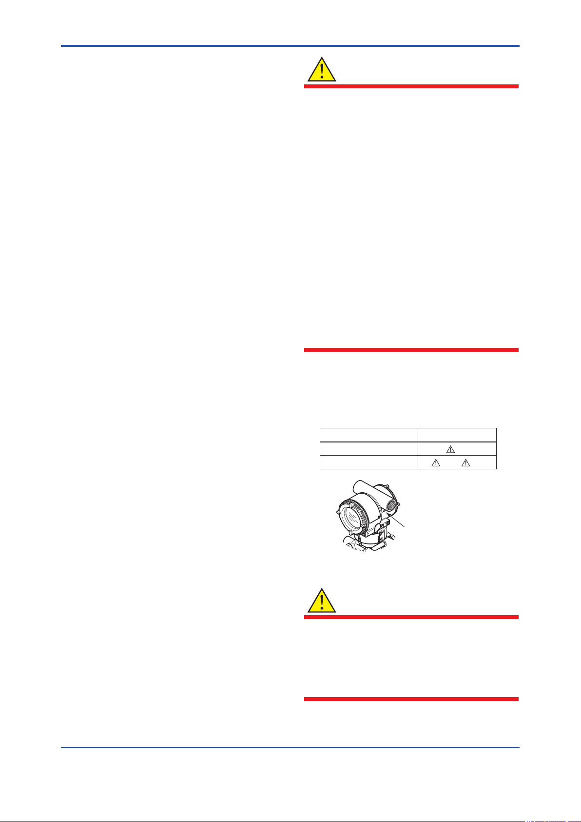
• The following safety symbols are used in this
manual:
WARNING
Indicates a potentially hazardous situation which,
if not avoided, could result in death or serious
injury.
CAUTION
Regarding This Manual
• This manual should be passed on to the end
user.
• The contents of this manual are subject to
change without prior notice.
• All rights reserved. No part of this manual may
be reproduced in any form without Yokogawa’s
written permission.
• Yokogawa makes no warranty of any kind with
regard to this manual, including, but not limited
to, implied warranty of merchantability and
tness for a particular purpose.
• If any question arises or errors are found, or if
any information is missing from this manual,
please inform the nearest Yokogawa sales
ofce.
Indicates a potentially hazardous situation which,
if not avoided, may result in minor or moderate
injury. It may also be used to alert against unsafe
practices.
IMPORTANT
Indicates that operating the hardware or software
in this manner may damage it or lead to system
failure.
NOTE
Draws attention to information essential for
understanding the operation and features.
IM 01C25R03-01E
Page 9

<1. Introduction>
1-2
1.1 Safe Use of This Product
For the safety of the operator and to protect the
instrument and the system, please be sure to follow
this manual’s safety instructions when handling this
instrument. If these instructions are not heeded,
the protection provided by this instrument may be
impaired. In this case, Yokogawa cannot guarantee
that the instrument can be safely operated. Please
pay special attention to the following points:
(a) Installation
• This instrument may only be installed by an
engineer or technician who has an expert
knowledge of this device. Operators are not
allowed to carry out installation unless they
meet this condition.
• With high process temperatures, care must
be taken not to burn yourself by touching the
instrument or its casing.
• Never loosen the process connector nuts when
the instrument is installed in a process. This can
lead to a sudden, explosive release of process
uids.
• When draining condensate from the pressure
detector section, take appropriate precautions
to prevent the inhalation of harmful vapors and
the contact of toxic process uids with the skin
or eyes.
• When removing the instrument from a
hazardous process, avoid contact with the uid
and the interior of the meter.
(c) Operation
• Wait 5 min. after the power is turned off, before
opening the covers.
(d) Maintenance
• Please carry out only the maintenance
procedures described in this manual. If you
require further assistance, please contact the
nearest Yokogawa ofce.
• Care should be taken to prevent the build up of
dust or other materials on the display glass and
the name plate. To clean these surfaces, use a
soft, dry cloth.
(e) Explosion Protected Type Instrument
• Users of explosion proof instruments should
refer rst to section 2.1 (Installation of an
Explosion Protected Instrument) of this manual.
• The use of this instrument is restricted to those
who have received appropriate training in the
device.
• Take care not to create sparks when accessing
the instrument or peripheral devices in a
hazardous location.
(f) Modication
• Yokogawa will not be liable for malfunctions or
damage resulting from any modication made
to this instrument by the customer.
• All installation work shall comply with local
installation requirements and the local electrical
code.
(b) Wiring
• The instrument must be installed by an
engineer or technician who has an expert
knowledge of this instrument. Operators are not
permitted to carry out wiring unless they meet
this condition.
• Before connecting the power cables, please
conrm that there is no current owing through
the cables and that the power supply to the
instrument is switched off.
IM 01C25R03-01E
Page 10

<1. Introduction>
1.2 Warranty
• The warranty shall cover the period noted on
the quotation presented to the purchaser at the
time of purchase. Problems occurring during
the warranty period shall basically be repaired
free of charge.
• If any problems are experienced with this
instrument, the customer should contact the
Yokogawa representative from which this
instrument was purchased or the nearest
Yokogawa ofce.
• If a problem arises with this instrument,
please inform us of the nature of the problem
and the circumstances under which it
developed, including the model specication
and serial number. Any diagrams, data and
other information you can include in your
communication will also be helpful.
• The party responsible for the cost of xing the
problem shall be determined by Yokogawa
following an investigation conducted by
Yokogawa.
1-3
• The purchaser shall bear the responsibility for
repair costs, even during the warranty period, if
the malfunction is due to:
- Improper and/or inadequate maintenance by
the purchaser.
- Malfunction or damage due to a failure
to handle, use, or store the instrument in
accordance with the design specications.
- Use of the product in question in a location
not conforming to the standards specied by
Yokogawa, or due to improper maintenance
of the installation location.
- Failure or damage due to modication or
repair by any party except Yokogawa or an
approved representative of Yokogawa.
- Malfunction or damage from improper
relocation of the product in question after
delivery.
- Reason of force majeure such as res,
earthquakes, storms/oods, thunder/
lightening, or other natural disasters, or
disturbances, riots, warfare, or radioactive
contamination.
IM 01C25R03-01E
Page 11

<1. Introduction>
1.3 ATEX Documentation
This is only applicable to the countries in the European Union.
1-4
GB
DK
E
NL
SK
CZ
I
LT
LV
EST
PL
SF
P
F
D
S
SLO
H
BG
RO
M
GR
IM 01C25R03-01E
Page 12

<2. Handling Cautions>
2. Handling Cautions
2-1
2.1 Installation of an ExplosionProtected Instrument
If a customer makes a repair or modication to
an intrinsically safe or explosionproof instrument
and the instrument is not restored to its original
condition, its intrinsically safe or explosionproof
construction may be compromised and the
instrument may be hazardous to operate. Please
contact Yokogawa before making any repair or
modication to an instrument.
CAUTION
This instrument has been tested and certied
as being intrinsically safe or explosionproof.
Please note that severe restrictions apply to this
instrument’s construction, installation, external
wiring, maintenance and repair. A failure to abide
by these restrictions could make the instrument a
hazard to operate.
WARNING
2.1.1 FM approval
a. FM Explosionproof Type
Caution for FM Explosionproof type
Note 1. EJX multivariable transmitter with
optional code /FF1 is applicable for use in
hazardous locations:
• Applicable Standard: FM3600, FM3615,
FM3810, ANSI/NEMA 250
• Explosionproof for Class I, Division 1,
Groups B, C and D.
• Dust-ignitionproof for Class II/III, Division 1,
Groups E, F and G.
• Enclosure rating: NEMA TYPE 4X.
• Temperature Class: T6
• Ambient Temperature: –40 to 60ºC
• Supply Voltage: 32V dc max.
• Current Draw: 15 mA dc
Note 2. Wiring
• All wiring shall comply with National Electrical
Code ANSI/NFPA70 and Local Electrical
Codes.
• When installed in Division 1, “FACTORY
SEALED, CONDUIT SEAL NOT
REQUIRED.”
Maintaining the safety of explosionproof
equipment requires great care during mounting,
wiring, and piping. Safety requirements also
place restrictions on maintenance and repair.
Please read the following sections very carefully.
WARNING
The range setting switch must not be used in a
hazardous area.
IMPORTANT
All the blind plugs which accompany the EJX
transmitters upon shipment from the factory are
certied by the applicable agency in combination
with the EJX series transmitters. The plugs which
are marked with the symbols “◊ Ex” on their
surfaces are certied only in combination with
the EJX series transmitters.
Note 3. Operation
• Keep the “WARNING” nameplate attached to
the transmitter.
WARNING: OPEN CIRCUIT BEFORE
REMOVING COVER. FACTORY SEALED,
CONDUIT SEAL NOT REQUIRED. INSTALL
IN ACCORDANCE WITH THE USERS
MANUAL IM 01C25.
• Take care not to generate mechanical
sparking when accessing the instrument and
peripheral devices in a hazardous location.
Note 4. Maintenance and Repair
• The instrument modication or parts
replacement by other than authorized
representative of Yokogawa Electric
Corporation is prohibited and will void
Factory Mutual Explosionproof Approval.
IM 01C25R03-01E
Page 13
<2. Handling Cautions>
2-2
b. FM Intrinsically safe and Nonincendive
Type
EJX multivariable transmitter with optional code
/FS15.
• Applicable standard: FM3600, FM3610,
FM3611, FM3810, ANSI/NEMA250,
IEC60079-27
• FM Intrinsically Safe Approval
[Entity Model]
Class I, II & III, Division 1, Groups A, B, C,
D, F & G, Temperature Class T4 Ta=60ºC,
Type 4X and Class I, Zone 0, AEx ia IIC,
Temperature Class T4 Ta=60ºC, Type 4X
[FISCO Model]
Class I, II & III, Division 1, Groups A, B, C,
D, F & G, Temperature Class T4 Ta=60ºC,
Type 4X and Class I, Zone 0, AEx ia IIC,
Temperature Class T4 Ta=60ºC, Type 4X
• Nonincendive Approval
Class I, Division 2, Groups A, B, C & D
Temperature Class T4 Ta=60ºC, Type 4X
and Class II, Division 2, Groups F & G
Temperature Class T4 Ta=60ºC, Type 4X
and Class I, Zone 2, Group IIC, Temperature
Class T4 Ta=60ºC, Type 4X and Class III,
Division 1, Temperature Class T4 Ta=60ºC,
Type 4X
• Electrical Connection: 1/2 NPT female, M20
female
• Caution for FM Intrinsically safe type.
(Following contents refer to “DOC. No.
IFM026-A12 p.1 to p.4.”)
■ IFM026-A12
● Installation Diagram for Intrinsically safe
(Division 1 Installation)
Terminator
+
Pressure
–
Transmitter
+
Field Instruments
–
+
Field Instruments
–
Hazardous Location
Terminator
+
Safety Barrier
+
–
–
Non-Hazardous Location
F0201.ai
Note 1. Barrier must be installed in an enclosure
that meets the requirements of ANSI/ISA
61010-1.
Note 2. Control equipment connected to the Associ
ated Apparatus must not use or generate
more than 250 Vrms or Vdc.
Note 3. Installation should be in accordance
with ANSI/ISA 12.06.01 “Installation of
Intrinsi cally Safe Systems for Hazardous
(Classied) Locations” and the National
Electrical Code (ANSI/NFPA 70) Sections
504 and 505.
Note 4. The conguration of Associated Apparatus
must be Factory Mutual Research
Approved under FISCO Concept.
Note 5. Associated Apparatus manufacturer’s
installa tion drawing must be followed
when installing this equipment.
Note 6. No revision to drawing without prior
Factory Mutual Research Approval.
Note 7. Terminator must be FM Approved.
Note 8. Note a warning label worded “SUBSTITU
TION OF COMPONENTS MAY IMPAIR
INTRINSIC SAFETY”, and “INSTALL IN
ACCORDANCE DOC.NO.IFM026-A12 P.1
TO 4.”
Electrical Data:
• Rating 1 (Entity)
For Groups A, B, C, D, F, and G or Group IIC
Maximum Input Voltage Vmax: 24 V
Maximum Input Current Imax: 250 mA
Maximum Input Power Pmax: 1.2 W
Maximum Internal Capacitance Ci: 3.52 nF
Maximum Internal Inductance Li: 0 mH
or
• Rating 2 (FISCO)
For Groups A, B, C, D, F, and G or Group IIC
Maximum Input Voltage Vmax: 17.5 V
Maximum Input Current Imax: 380 mA
Maximum Input Power Pmax: 5.32 W
Maximum Internal Capacitance Ci: 3.52 nF
Maximum Internal Inductance Li: 0 mH
or
• Rating 3 (FISCO)
For Groups C, D, F, and G or Group IIB
Maximum Input Voltage Vmax: 17.5 V
Maximum Input Current Imax: 460 mA
Maximum Input Power Pmax: 5.32 W
Maximum Internal Capacitance Ci: 3.52 nF
Maximum Internal Inductance Li: 0 mH
IM 01C25R03-01E
Page 14

<2. Handling Cautions>
2-3
Sensor Circuit: Uo=6.51 V, Io=4 mA,
Po=6 mW, Co=34 µF, Lo=500 mH
Note: In the rating 1, the output current of the barrier must
be limited by a resistor “Ra” such that Io=Uo/Ra. In the
rating 2 or 3, the output characteristics of the barrier
must be the type of trapezoid which are certied as
the FISCO model (See “FISCO Rules”). The safety
barrier may include a terminator. More than one eld
instruments may be connected to the power supply
line.
● FISCO Rules
The FISCO Concept allows the interconnection
of intrinsincally safe apparatus to associated
apparatus not specically examined in such
combination. The criterion for such interconnection
is that the voltage (Ui), the current (Ii) and the power
(Pi) which intrinsically safe apparatus can receive
and remain intrinsically safe, considering faults,
must be equal or greater than the voltage (Uo,
Voc, Vt), the current (Io, Isc, It) and the power (Po)
which can be provided by the associated apparatus
(supply unit).
Po ≤ Pi, Uo ≤ Ui, Io ≤ Ii
In addition, the maximum unprotected residual
capacitance (Ci) and inductance (Li) of each
apparatus (other than the terminators) connected to
the eldbus must be less than or equal to 5 nF and
10 µH respectively.
Ci ≤ 5nF, Li ≤ 10µH
In each I.S. eldbus segment only one active
source, normally the associated apparatus, is
allowed to provide the necessary power for the
eldbus system. The allowed voltage(Uo, Voc,Vt)
of the associated apparatus used to supply the
bus cable must be limited to the range of 14 V dc
to 17.5 V dc. All other equipment connected to
the bus cable has to be passive, meaning that the
apparatus is not allowed to provide energy to the
system, except to a leakage current of 50 µA for
each connected device.
Supply unit
Trapezoidal or rectangular output characteristic only
Cable
The cable used to interconnect the devices needs
to comply with the following parameters:
Loop resistance R': 15...150 Ω/km
Inductance per unit length L': 0.4...1 mH/km
Capacitance per unit length C': 45...200 nF/km.
C'=C' line/line + 0.5 C' line/screen, if both lines
are oating or C'=C' line/line + C' line/screen, if
the screen is connected to one line.
Length of spur cable: max. 60 m
Length of trunk cable: max. 1 km (Group IIC) or
5 km (Group IIB)
Length of splice: max.1m
Terminators
At each end of the trunk cable an FM approved line
terminator with the following parameters is suitable:
R = 90...100 Ω
C = 0...2.2 mF
System evaluations
The number of passive device like transmitters,
actuators, hand held terminals connected to
a single bus segment is not limited due to I.S.
reasons. Furthermore, if the above rules are
respected, the inductance and capacitance of the
cable need not to be considered and will not impair
the intrinsic safety of the installation.
SAFE AREAHAZARDOUS AREA
Terminator
(FISCO Model)
Ex i
Hand-
held-
Terminal
Field Instruments
(Passive)
I.S. eldbus system complying with FISCO model
Supply Unit and
Safety Barrier
(FISCO Model)
U
I
Terminator
Data
F0202.ai
U
Uo = 14...17.5 V (I.S. maximum value)
Io according to spark test result or other
assessment. No specication of Lo and Co is
required on the certicate or label.
IM 01C25R03-01E
Page 15
<2. Handling Cautions>
2-4
● Installation Diagram for Nonincendive
(Division 2 Installation)
Terminator
+
SUPPLY
–
Pressure
Transmitter
+
Transmitter
–
+
Transmitter
–
Hazardous Location
Non-Hazardous Location
Terminator
FM Approved
+ –
General Purpose
Equipment
+ –
Associated Nonincendive Field
Wiring Apparatus
Vt or Voc
It or Isc
Ca
La
F0203.ai
Note 1. Installation should be in accordance with
the National Electrical Code ® (ANSI/NFPA
70) Article 500.
Note 2. The conguration of Associated
Nonincendive Field Wiring Apparatus must
be FM Approved.
Note 3. Approved under FNICO Concept.
Note 4. Dust-tight conduit seal must be used
when installed in Class II and Class III
environments.
Note 5. Associated Apparatus manufacturer’s
installation drawing must be followed when
installing this apparatus.
Note 6. No revision to drawing without prior FM
Approvals.
Note 7. Terminator must be FM Approved.
Note 8. The nonincendive eld wiring circuit
concept allows interconection of
nonincendive eld wiring apparatus with
associated nonincendive eld wiring
apparatus, using any of the wiring methods
permitted for unclassied locations.
Note 9. Installation requirements;
Vmax ≥ Voc or Vt
Imax = see note 10.
Ca ≥ Ci + Ccable
La ≥ Li + Lcable
Note 10. For this current controlled circuit, the
parameter (Imax) is not required and need
not be aligned with parameter (Isc) of the
barrier or associated nonincendive eld
wiring apparatus.
Note 11. If ordinary location wiring methods are
used, the transmitter shall be connected
to FM Approved associated nonincendive
eld wiring apparatus.
Electrical data:
Vmax: 32V
Ci:1.76 nF
Li: 0 µH
● FNICO Rules
The FNICO Concept allows the interconnection of
nonincendive eld wiring apparatus to associated
nonincendive eld wiring apparatus not specically
examined in such combination. The criterion for
such interconnection is that the voltage (Vmax),
the current (Imax) and the power (Pmax) which
nonincendive eld wiring apparatus can receive and
remain nonincendive, considering faults, must be
equal or greater than the voltage (Uo, Voc or Vt),
the current (Io, Isc or It) and the power (Po) which
can be provided by the associated nonincendive
eld wiring apparatus (supply unit). In addition the
maximum unprotected residual capacitance (Ci)
and inductance (Li) of each apparatus (other than
terminators) connected to the Fieldbus must be less
than or equal to 5nF and 20uH respectively.
In each N.I. Fieldbus segment only one active
source, normally the associated nonincendive
eld wiring apparatus, is allowed to provide the
necessary power for the Fieldbus system. The
allowed voltage (Uo, Voc or Vt) of the associated
nonincendive eld wiring apparatus used to supply
the bus cable must be limited to the range 14Vdc
to 17.5Vdc. All other equipment connected to the
bus cable has to be passive, meaning that the
apparatus is not allowed to provide energy to the
system, except a leakage current of 50 µA for each
connected device. Separately powered equipment
needs galvanic isolation to ensure the nonincendive
eld wiring Fieldbus circuit remains passive.
IM 01C25R03-01E
Page 16

<2. Handling Cautions>
2-5
Cable
The cable used to interconnect the devices needs
to comply with the following parameters:
Loop resistance R': 15...150 Ω/km
Inductance per unit length L': 0.4...1 mH/km
Capacitance per unit length C': 45....200 nF/km
C' =C' line/line+0.5 C' line/screen, if both lines
are oating or C' = C' line/line + C' line/screen, if
the screen is connected to one line.
Length of spur cable: max. 60 m
Length of trunk cable: max. 1 km (Group IIC) or
5 km (Group IIB)
Length of splice: max = 1 m
Terminators
At the end of each trunk cable an FM Approved line
terminator with the following parameters is suitable:
R= 90...100 Ω
C = 0 ....2.2 mF
2.1.2 CSA Certication
a. CSA Explosionproof Type
Caution for CSA explosionproof type.
Note 1. EJX multivariable transmitter with
optional code /CF1 is applicable for use in
hazardous locations:
Certicate: 2014354
• Applicable Standard:
C22.2 No.0, C22.2 No.0.4, C22.2 No.0.5,
C22.2 No.25, C22.2 No.30, C22.2 No.94,
C22.2 No.61010.1-01, C22.2 No.60079-0,
C22.2 No.60079-1
[For CSA C22.2]
• Explosion-proof for Class I, Groups B, C and
D.
• Dustignition-proof for Class II/III, Groups E, F
and G.
• Enclosure: TYPE 4X
• Temperature Code: T6...T4
[For CSA E60079]
• Flameproof for Zone 1, Ex d IIC T6...T4
• Enclosure: IP66 and IP67
• Maximum Process Temperature: 120ºC (T4),
100ºC (T5), 85ºC (T6)
• Ambient Temperature: –50* to 75ºC (T4),
–50* to 80ºC (T5), –50* to 72ºC (T6)
* –15ºC when /HE is specied.
• Supply Voltage: 32 V dc max.
• Output Signal: 15 mA dc
Note 2. Wiring
• All wiring shall comply with Canadian
Electrical Code Part I and Local Electrical
Codes.
• In hazardous location, wiring shall be in
conduit as shown in the gure.
• WARNING:
A SEAL SHALL BE INSTALLED WITHIN
50cm OF THE ENCLOSURE.
UN SCELLEMENT DOIT ÊTRE INSTALLÉÀ
MOINS DE 50cm DU BOîTIER.
• WARNING:
WHEN INSTALLED IN CL.I, DIV 2, SEAL
NOT REQUIRED.
UNE FOIS INSTALLÉ DANS CL I, DIV 2,
AUCUN JOINT N'EST REQUIS.
Note 3. Operation
• WARNING:
AFTER DE-ENERGIZING, DELAY 5
MINUTES BEFORE OPENING.
APRÉS POWER-OFF, ATTENDRE 5
MINUTES AVANT D'OUVRIR.
• WARNING:
WHEN AMBIENT TEMPERATURE ≥ 65ºC,
USE THE HEAT-RESISTING CABLES ≥
90ºC.
QUAND LA TEMPÉRATURE AMBIANTE
≥ 65ºC, UTILISEZ DES CÂBLES
RÉSISTANTES Á LA CHALEUR ≥ 90ºC.
• Take care not to generate mechanical
sparking when accessing to the instrument
and peripheral devices in a hazardous
location.
Note 4. Maintenance and Repair
• The instrument modication or parts
replacement by other than authorized
representative of Yokogawa Electric
Corporation and Yokogawa Corporation of
America is prohibited and will void Canadian
Standards Explosionproof Certication.
IM 01C25R03-01E
Page 17

<2. Handling Cautions>
2-6
Non-Hazardous
Locations
Non-hazardous
Location
Equipment
32 V DC Max.
15 mA DC
Signal
Non-Hazardous
Locations
Non-hazardous
Location
Equipment
32 V DC Max.
15 mA DC
Signal
Hazardous Locations Division 1
50 cm Max.
PULSE
PULSE
SUPPLY
SUPPLY
CHECK
CHECK
ALARM
Sealing Fitting
Conduit
Multivariable Transmitter
Hazardous Locations Division 2
Sealing Fitting
Multivariable Transmitter
ALARM
PULSE
PULSE
SUPPLY
SUPPLY
CHECK
CHECK
ALARM
ALARM
F0204.ai
2.1.3 ATEX Certication
(1) Technical Data
a. ATEX Intrinsically Safe Type
Caution for ATEX Intrinsically safe type.
Note 1. EJX multivariable transmitter with optional
code /KS26 for potentially explosive
atmospheres:
• No. KEMA 06ATEX0278 X
• Applicable Standard: EN 60079-0:2009,
EN 60079-11:2012, EN 60079-26:2007
Note 2. Ratings
Type of Protection and Marking Code:
Ex ia IIC/IIB T4 Ga
Ex ia IIIC T85°C T100°C T120°C Db
Group: II
Category: 1G, 2D
Ambient Temperature for EPL Ga:
–40 to 60°C
Ambient Temperature for EPL Db:
–30* to 60°C
* –15°C when /HE is specied.
Maximum Process Temperature (Tp.): 120°C
Maximum Surface Temperature for EPL Db.
T85°C (Tp.: 80°C)
T100°C (Tp.: 100°C)
T120°C (Tp.: 120°C)
Ambient Humidity:
0 to 100% (No condensation)
Degree of Protection of the Enclosure:
IP66/IP67
Electrical Data
• When combined with Trapezoidal or
Rectanglar output characteristic FISCO
model IIC barrier
[Supply circuit (terminals + and -)]
Ui = 17.5 V, Ii = 380 mA, Pi = 5.32 W,
Ci = 3.52 nF, Li = 0 µH
[Sensor circuit]
Uo = 7.63 V, Io = 3.85 mA, Po = 0.008 W,
Co = 4.8 µF, Lo = 100 mH
• When combined with Linear characteristic
barrier
[Supply circuit (terminals + and -)]
Ui = 24 V, Ii = 250 mA, Pi = 1.2 W,
Ci = 3.52 nF, Li = 0 µH
[Sensor circuit]
Uo = 7.63 V, Io = 3.85 mA, Po = 0.008 W,
Co = 4.8 µF, Lo = 100 mH
• When combined with Trapezoidal or
Rectanglar output characteristic FISCO
model IIB barrier
[Supply circuit (terminals + and -)]
Ui = 17.5 V, Ii = 460 mA, Pi = 5.32 W,
Ci = 3.52 nF, Li = 0 µH
[Sensor circuit]
Uo = 7.63 V, Io = 3.85 mA, Po = 0.008 W,
Co = 4.8 µF, Lo = 100 mH
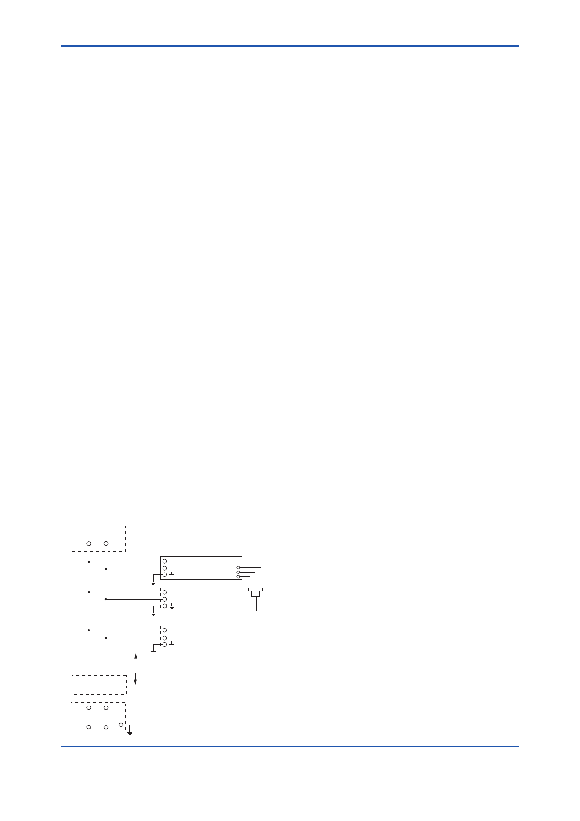
Note 3. Installation
• All wiring shall comply with local installation
requirements. (Refer to the installation
diagram)
Note 4. Maintenance and Repair
• The instrument modication or parts
replacement by other than authorized
representative of Yokogawa Electric
Corporation is prohibited and will void
DEKRA Intrinsically safe Certication.
Note 5. Special Conditions for Safe Use
IM 01C25R03-01E
Page 18
<2. Handling Cautions>
• In the rating 1(*1), the output current of the
WARNING
barrier must be limited by a resistor ‘Ra’ such
that Io = Uo/Ra.
• In the case where the enclosure of the
Pressure Transmitter is made of aluminium,
if it is mounted in an area where the use of
category 1G apparatus is required, it must be
installed such, that even in the event of rare
incidents, ignition sources due to impact and
friction sparks are excluded.
• Electrostatic charge may cause an explosion
hazard. Avoid any actions that cause the
generation of electrostatic charge, such as
rubbing with a dry cloth on coating face of
the product.
• In the case where the enclosure of the
Pressure Transmitter is made of aluminum,
if it is mounted in an area where the use of
category 2D apparatus is required, it shall
be installed in such a way that the risk from
electrostatic discharges and propagating
brush discharges caused by rapid ow of
dust is avoided.
• To satisfy IP66 or IP67, apply waterproof
glands to the electrical connection port.
• When the lightning protector option is
specied, the apparatus is not capable
of withstanding the 500V insulation test
required by EN60079-11.
This must be taken into account when
installing the apparatus.
• In the rating 2(*2), the output of the barrier
must be the characteristics of the trapezoid
or the rectangle and this transmitter can be
connected to Fieldbus equipment which are
in according to the FISCO model.
• The terminators may be built in by a barrier.
• More than one transmitter may be connected
to the power supply line.
• The terminator and the safety barrier shall be
certied.
Electrical data:
Supply circuit
Maximum Input Voltage Ui: 24 V
Maximum Input Current Ii: 250 mA
Maximum Input Power Pi: 1.2 W
Maximum Internal Capacitance Ci: 3.52 nF
Maximum Internal Inductance Li: 0 μH
or
Maximum Input Voltage Ui: 17.5 V
Maximum Input Current Ii: 380 mA
Maximum Input Power Pi: 5.32 W
Maximum Internal Capacitance Ci: 3.52 nF
Maximum Internal Inductance Li: 0 μH
or
Maximum Input Voltage Ui: 17.5 V
Maximum Input Current Ii: 460 mA
Maximum Input Power Pi: 5.32 W
Maximum Internal Capacitance Ci: 3.52 nF
Maximum Internal Inductance Li: 0 μH
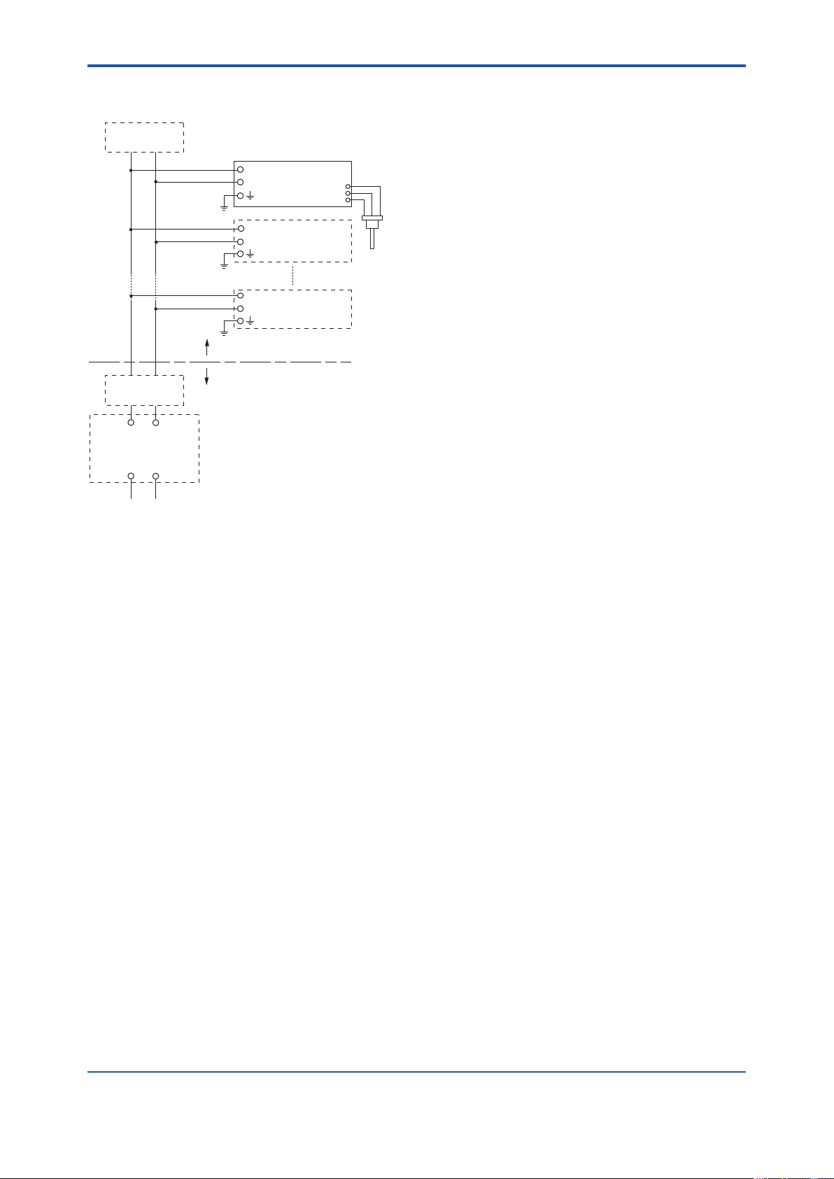
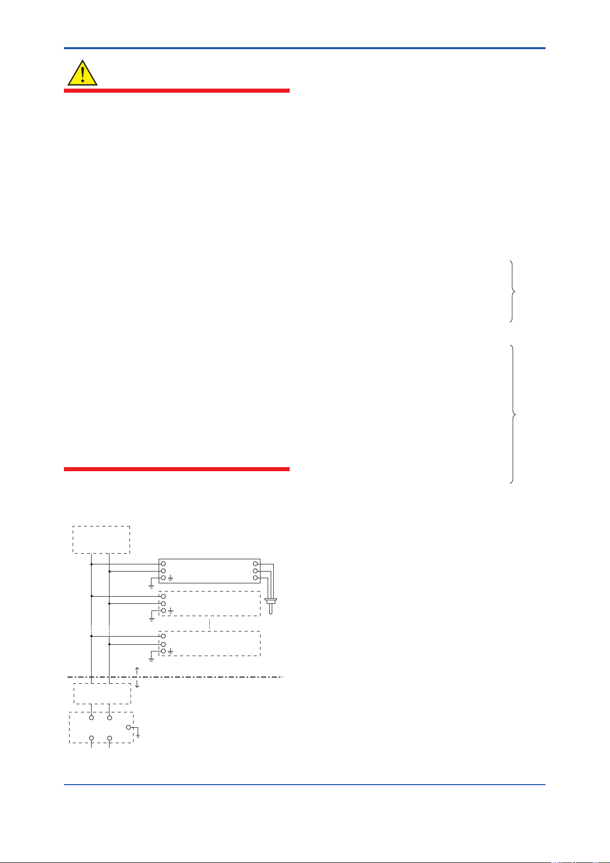
Note 6. Installation instructions
[Installation Diagram]
Sensor circuit
Maximum Output Voltage Uo: 7.63 V
Terminator
+
SUPPLY
−
RTD
Pt100.3wire
Pressure
Transmitter
Maximum Output Current Io: 3.85 mA
Maximum Output Power Po: 0.008 W
Maximum Internal Capacitance Co: 4.8 μF
Maximum Internal Inductance Lo: 100 mH
2-7
*1:
Rating 1
*2:
Rating 2
Terminator
+
Safety Barrier
+
−
−
+
Transmitter
−
+
Transmitter
−
Hazardous Location
Non-Hazardous Location
• RTD sensor is prepared by the user.
The sensor signal line must suited a test
voltage of 500Vac.
F0308.ai
IM 01C25R03-01E
Page 19
<2. Handling Cautions>
b. ATEX Flameproof Type
Caution for ATEX ameproof type
WARNING
2-8
Note 1. Model EJX Series pressure transmitters
with optional code /KF22 for potentially
explosive atmospheres:
• No. KEMA 07ATEX0109 X
• Applicable Standard: EN 60079-0:2009,
EN 60079-1:2007, EN 60079-31:2009
• Type of Protection and Marking Code:
Ex d IIC T6...T4 Gb, Ex tb IIIC T85°C Db
• Group: II
• Category: 2G, 2D
• Enclosure: IP66 / IP67
• Temperature Class for gas-poof:
T6, T5, and T4
• Ambient Temperature for gas-proof:
–50 to 75°C (T6), –50 to 80°C (T5), and
–50 to 75°C (T4)
• Maximum Process Temperature (Tp.) for
gas-proof:
85°C (T6), 100°C (T5), and 120°C (T4)
• Maximum Surface Temperature for dustproof:
T85°C (Tamb.: –30* to 75°C, Tp.: 85°C)
* –15°C when /HE is specied.
• Electrostatic charge may cause an exlosion
hazard. Avoid any actions that cause the
gerenation of eletrostatic charge, such as
rubbing with a dry cloth on coating face of the
product.
• In the case where the enclosure of the
Pressure Transmitter is made of aluminium,
if it is mounted in an area where the use of
category 2D apparatus is required, it shall
be installed in such a way that the risk from
electrostatic discharges and propagating
brush discharges caused by rapid ow of
dust is avoided.
• The instrument modication or parts
replacement by other than an authorized
Representative of Yokogawa Electric
Corporation is prohibited and will void the
certication.
• To satisfy IP66 or IP67, apply waterproof
glands to the electrical connection port.
(2) Electrical Connection
Note 2. Electrical Data
• Supply voltage: 42 V dc max.
• Output signal: 4 to 20 mA
Note 3. Installation
• All wiring shall comply with local installation
requirement.
• The cable entry devices shall be of a certied
ameproof type, suitable for the conditions of
use.
Note 4. Operation
• Keep the “WARNING” label attached to the
transmitter.
WARNING: AFTER DE-ENERGIZING,
DELAY 5 MINUTES BEFORE OPENING.
WHEN THE AMBIENT TEMP.≥65°C, USE
HEAT-RESISTING CABLE AND CABLE
GLAND ≥90°C.
• Take care not to generate mechanical
sparking when accessing to the instrument
and peripheral devices in a hazardous
location.
Note 5. Special Conditions for Safe Use
A mark indicating the electrical connection type is
stamped near the electrical connection port. These
marks are as follows.
MarkingScrew Size
ISO M20×1.5 female
ANSI 1/2 NPT female
Location of the mark
M
N or W
F0207.ai
(3) Installation
WARNING
• All wiring shall comply with local installation
requirements and the local electrical code.
• There is no need for a conduit seal in
Division 1 and Division 2 hazardous
locations because this product is sealed at
the factory.
IM 01C25R03-01E
Page 20
<2. Handling Cautions>
2-9
(4) Operation
WARNING
• OPEN CIRCUIT BEFORE REMOVING
COVER. INSTALL IN ACCORDANCE WITH
THIS USER’S MANUAL
• Take care not to generate mechanical
sparking when accessing the instrument and
peripheral devices in a hazardous location.
(5) Maintenance and Repair
WARNING
The instrument modication or part replacement
by other than an authorized Representative of
Yokogawa Electric Corporation is prohibited and
will void the certication.
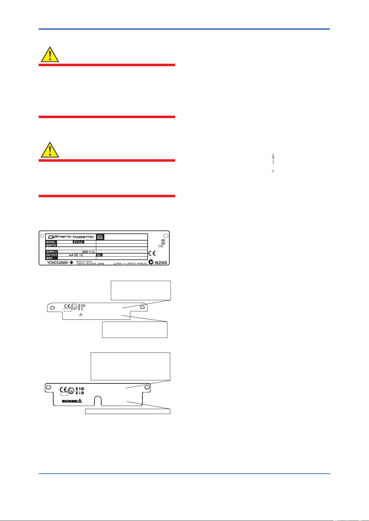
(6) Name Plate
● Name plate
MODEL: Specied model code.
STYLE: Style code.
SUFFIX: Specied sufx code.
SUPPLY: Supply voltage.
OUTPUT: Output signal.
MWP: Maximum working pressure.
CAL RNG: Specied calibration range.
NO.: Serial number and year of production*1.
TOKYO 180-8750 JAPAN:
The manufacturer name and the address*2.
*1: The rst digit in the nal three numbers of the serial
number appearing after “NO.” on the name plate
indicates the year of production. The following is an
example of a serial number for a product that was
produced in 2010:
91K819857 032
The year 2010
*2: “180-8750” is the Zip code for the following address.
2-9-32 Nakacho, Musashino-shi, Tokyo Japan
*3: The identication number of Notied Body.
2.1.4 IECEx Certication
a. IECEx Flameproof Type
Tag plate for flameproof type
No. KEMA 07ATEX0109 X
Ex d IIC T6...T4 Gb, Ex tb IIIC T85°C Db
Enlcosure : IP66, IP67
TEMP. CLASS T6 T5 T4
MAX PROCESS TEMP.(Tp.) 85 100 120 °C
Tamb. -50 to 75 80 75 °C
T85°C(Tamb.:-30(-15) to 75°C, Tp.:85°C)(for Dust)
WARNING
D
AFTER DE-ENERGIZING, DELAY 5 MINUTES BEFORE
OPENING.
WHEN THE AMBIENT TEMP. ≥ 65°C, USE THE
HEAT-RESISTING CABLE & CABLE GLAND ≥ 90°C
POTENTIAL ELECTROSTATIC CHARGING HAZARD
*3
Tag plate for intrinsically safe type
No. KEMA 06ATEX0278 X
Ex ia IIC/IIB T4 Ga Ta: -40 to 60°C
Ex ia IIIC T85°C T100°C T120°C Db Ta: -30(-15) to 60°C
MAX PROCESS TEMP.(Tp.): 120°C
T85°C (Tp.: 80°C), T100°C (Tp.: 100°C), T120°C (Tp.: 120°C)
ENCLOSURE: IP66/IP67
Supply circuit
FISCO field device(IIC/IIB)
Entity Parameter Ui=24V, Ii=250mA, Pi=1.2W, Ci=3.52nF, Li=0µH
Sensor circuit
Uo=7.63V, Io=3.85mA, Po=0.008W, Co=4.8uF, Lo=100mH
*3
POTENTIAL ELECTROSTATIC CHARGING HAZARD-SEE USER'S MANUAL.
Caution for IECEx ameproof type.
Note 1. EJX multivariable transmitters with optional
code /SF2 are applicable for use in
hazardous locations:
• No. IECEx CSA 07.0008
• Applicable Standard: IEC60079-0:2004,
IEC60079-1:2003
• Flameproof for Zone 1, Ex d IIC T6...T4
• Enclosure: IP66 and IP67
• Maximum Process Temperature: 120ºC (T4),
100ºC (T5), 85ºC (T6)
• Ambient Temperature: –50 to 75ºC (T4),
–50 to 80ºC (T5), –50 to 75ºC (T6)
• Supply Voltage: 32 V dc max.
• Output Signal: 15 mA dc
F0208.ai
IM 01C25R03-01E
Page 21

<2. Handling Cautions>
Note 2. Wiring
• In hazardous locations, the cable entry
devices shall be of a certied ameproof
type, suitable for the conditions of use and
correctly installed.
• Unused apertures shall be closed with
suitable ameproof certied blanking
elements.
Note 3. Operation
• WARNING:
AFTER DE-ENERGIZING, DELAY 5
MINUTES BEFORE OPENING.
• WARNING:
WHEN AMBIENT TEMPERATURE ≥ 65ºC,
USE THE HEAT-RESISTING CABLES ≥
90ºC.
• Take care not to generate mechanical
sparking when accessing to the instrument
and peripheral devices in a hazardous
location.
2-10
Note 4. Maintenance and Repair
• The instrument modication or parts
replacement by other than authorized
representative of Yokogawa Electric
Corporation is prohibited and will void IECEx
Certication.
IM 01C25R03-01E
Page 22

<3. About Fieldbus>
3. About Fieldbus
3-1
3.1 Outline
Fieldbus is a widely used bi-directional digital
communication protocol for eld devices that
enable the simultaneous output to many types of
data to the process control system.
The EJX multivariable transmitter Fieldbus
communication type employs the specication
standardized by The Fieldbus Foundation, and
provides interoperability between Yokogawa
devices and those produced by other
manufacturers. Fieldbus comes with software
consisting of ve AI function blocks that enable the
exible implementation of systems.
For information on other features, engineering,
design, construction work, startup and maintenance
of Fieldbus, refer to “Fieldbus Technical Information”
(TI 38K03A01-01E).
3.2 Internal Structure of EJX Multivariable Transmitter
(2) SENSOR Transducer block
• Converts sensor output to pressure, static
pressure, and capsule temperature signals,
and transfers to the AI function blocks and ow
transducer blok.
(3) FLOW Transducer block
• Accepts differential pressure, static pressure
and external temperature data from the
transducer block, calculates ow, and transfer
to the AI function block.
(4) LCD Transducer block
• Controls the display of the integral indicator.
(5) AI function block
• Condition raw data from the Transducer block.
• Output differential pressure, static pressure and
capsule temperature signals.
• Carry out scaling, damping and square root
extraction.
(6) SC function block
The EJX Multivariable transmitter contains two
virtual eld devices (VFD) that share the following
functions.
3.2.1 System/network Management VFD
• Sets node addresses and Physical Device tags
(PD Tag) necessary for communication.
• Controls the execution of function blocks.
• Manages operation parameters and
communication resources (Virtual
Communication Relationship: VCR).
3.2.2 Function Block VFD
(1) Resource block
• Manages the status of EJX hardware.
• Automatically informs the host of any detected
faults or other problems.
• Converts the input signal value based on the
segment table function.
(7) IT function block
• Integrates one or two input signals and outputs
the result.
(8) IS function block
• Selects one of multiple input signals according
to the specied selection method and outputs
the signal.
(9) AR function block
• Performs ten types of calculations on a
combination of two main input signals and three
auxiliary input signals.
(10) PID function block
• Performs the PID control computation based on
the deviation of the measured value from the
setpoint.
IM 01C25R03-01E
Page 23
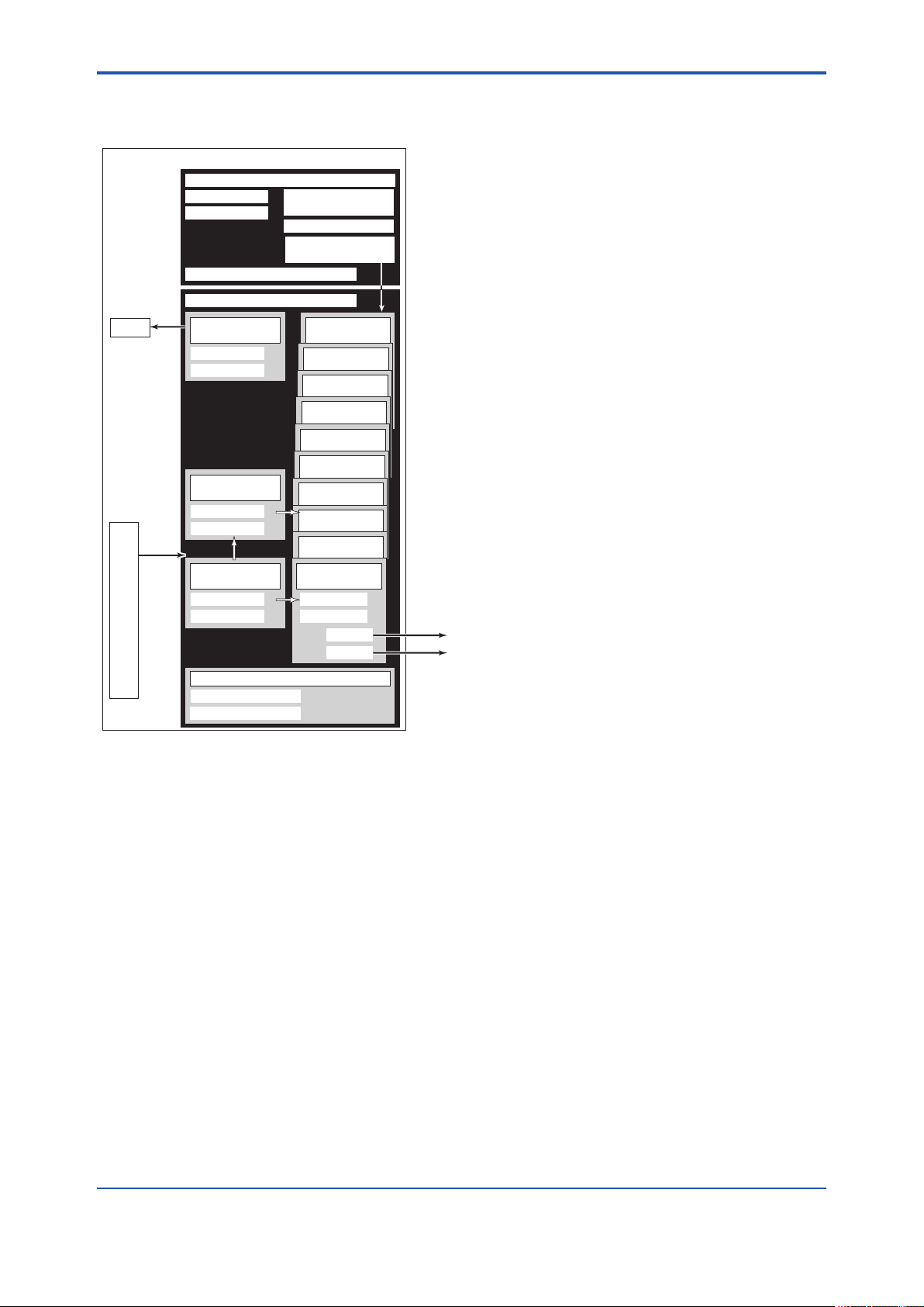
<3. About Fieldbus>
3.3 Logical Structure of Each Block
EJX Multivariable Transmitter
Fieldbus
LCD
Sensor
input
Sensor
System/network management VFD
PD Tag
Node address
Link Master
Function block VFD
LCD
Transducer block
Block tag
Parameters
Flow
Transducer block
Block tag
Parameters
SENSOR
Transducer block
Block tag
Parameters
Communication
parameters
VCR
Function block
execution schedule
PID function
block (option)
AR function
block
IS function
block
IT function
block
SC function
block
AI function
block
AI function
block
AI function
block
AI function
block
AI function
block
Block tag
Parameters
OUT_D
Output
OUT
3-2
Resource block
Block tag
Parameters
F0301.ai
Figure 3.1 Logical Structure of Each Block
Setting of various parameters, node addresses,
and PD Tags shown in Figure 3.1 is required before
starting operation.
3.4 Wiring System Conguration
The number of devices that can be connected to
a single bus and the cable length vary depending
on system design. When constructing systems,
both the basic and overall design must be carefully
considered to achieve optimal performance.
IM 01C25R03-01E
Page 24

<4. Getting Started>
4. Getting Started
4-1
Fieldbus is fully dependent upon digital
communication protocol and differs in operation
from conventional 4 to 20 mA transmission and the
HART communication protocol. It is recommended
that novice users use eld devices in accordance
with the procedures described in this section. The
procedures assume that eld devices will be set up
on a bench or in an instrument shop.
4.1 Connection of Devices
The following are required for use with Fieldbus
devices:
• Power supply:
Fieldbus requires a dedicated power supply. It
is recommended that current capacity be well
over the total value of the maximum current
consumed by all devices (including the host).
Conventional DC current cannot be used as is.
• Terminator:
period of within 5 cm (2 inches) may be used.
Termination processing depends on the type of
device being deployed. For EJX multivariable
transmitter, use an M4 screw terminal claw.
Some hosts require a connector.
Refer to Yokogawa when making arrangements to
purchase the recommended equipment.
Connect the devices as shown in Figure 4.1.
Connect the terminators at both ends of the
trunk, with a minimum length of the spur laid for
connection.
The polarity of signal and power must be
maintained.
Fieldbus power
supply
Terminator
EJX
HOST
Fieldbus requires two terminators. Refer to
the supplier for details of terminators that are
attached to the host.
• Field devices:
Connect Fieldbus communication type EJX
multivariable transmitter. Two or more EJX
devices or other devices can be connected.
• Host:
Used for accessing eld devices. A
dedicated host (such as DCS) is used for
an instrumentation line while dedicated
communication tools are used for experimental
purposes. For operation of the host, refer to
the instruction manual for each host. No other
details on the host are given in this manual.
• Cable:
Used for connecting devices. Refer to “Fieldbus
Technical Information” (TI 38K03A01-01E)
for details of instrumentation cabling. For
laboratory or other experimental use, a twisted
pair cable two to three meters in length with a
cross section of 0.9 mm2 or more and a cycle
Figure 4.1 Cabling
RTD cable connection
Communication
terminals
connection hook
SUPPLY +
SUPPLY −
SUPPLY
CHECK
PULSE
Figure 4.2 Terminal Conguration
+
Power supply and output terminal
–
+
–
Not available for Fieldbus communication
type
+
–
Ground terminal
PULSE
SUPPLY
CHECK
ALARM
PULSE − / CHECK −
Terminator
F0401.ai
Check meter
connection hook
PULSE +
CHECK +
F0404.ai
IM 01C25R03-01E
Page 25
<4. Getting Started>
Table 4.1 Operation Parameters
NOTE
No CHECK terminal is used for Fieldbus EJX
multivariable transmitter. Do not connect the eld
indicator and check meter.
Before using a Fieldbus conguration tool other
than the existing host, conrm it does not affect the
loop functionality in which all devices are already
installed in operation. Disconnect the relevant
control loop from the bus if necessary.
IMPORTANT
Connecting a Fieldbus conguration tool
to a loop with its existing host may cause
communication data scrambling resulting in a
functional disorder or a system failure.
4.2 Host Setting
To activate Fieldbus, the following settings are
required for the host. Set the available address
range to cover the address set for EJX multivariable
transmitter's.
Symbol Parameter Description and Settings
V (ST) Slot-Time Indicates the time
necessary for immediate
reply of the device. Unit of
time is in octets (256 μs).
Set maximum
specication for all
devices. For EJX, set a
value of 4 or greater.
V (MID) Minimum-Inter-
PDU-Delay
V (MRD) Maximum-
Reply-Delay
V (FUN) First-Unpolled-
Node
V (NUN) Number-of-
consecutiveUnpolled-Node
Minimum value of
communication data
intervals. Unit of time is in
octets (256 μs). Set the
maximum specication for
all devices. For EJX, set a
value of 4 or greater.
The worst case time
elapsed until a reply is
recorded. The unit is
Slot-time; set the value
so that V (MRD) × V (ST)
is the maximum value
of the specication for
all devices. For EJX, the
setting must be a value of
12 or greater.
Indicate the address next
to the address range used
by the host. Set 0 × 15 or
greater.
Unused address range.
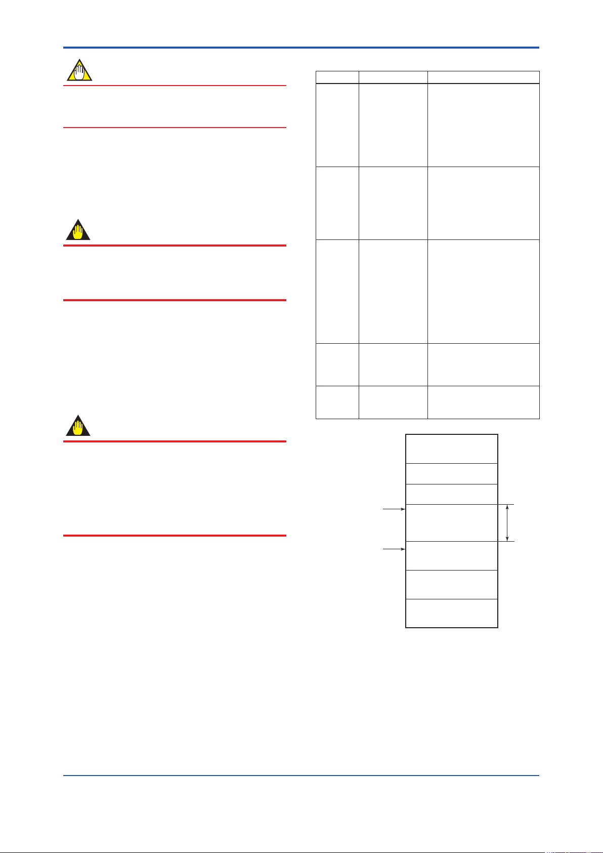
IMPORTANT
0x00
Do not turn off the power immediately after
setting. When the parameters are saved to the
EEPROM, the redundant processing is executed
for an improvement of reliability. If the power
is turned off within 60 seconds after setting is
made, the modied parameters are not saved
and the settings may return to the original values.
V(FUN)
0x0F
0x10
0x13
0x14
Not used
Bridge device
LM device
Unused V(NUN)
4-2
V(FUN)+V(NUN)
0xF7
0xF8
0xFB
0xFC
0xFF
Note 1: Bridge device: A linking device which brings data
from one or more H1 networks.
Note 2: LM device: with bus control function
(Link Master function)
Note 3: BASIC device: without bus control function
Figure 4.3 Available Address Range
BASIC device
Default address
Portable device address
IM 01C25R03-01E
F0402.ai
Page 26

<4. Getting Started>
4-3
4.3 Bus Power ON
Turn on the power of the host and the bus. Where
the EJX multivariable transmitter is equipped with
an LCD indicator, rst all segments are lit, then the
display begins to operate. If the indicator is not lit,
check the polarity of the power supply.
Using the host device display function, check that
the EJX multivariable transmitter is in operation on
the bus.
The device information, including PD tag, Node
address, and Device ID, is described on the sheet
attached to the device. The device information is
given in duplicate on this sheet.
Device ID : 594543000EXXXXXXXX
PD Tag : FT1001
Device Revision : 1
Node Address : 0xf5
Serial No. : XXXXXXXXXXXXXXXXX
Physical Location :
Note:
Our Device Description Files and Capabilities Files available at
http://www.yokogawa.com/fld/ (English) or
http://www.yokogawa.co.jp/fld/ (Japanese)
DEVICE INFORMATION
4.4 Integration of DD
If the host supports DD (Device Description), the
DD of the EJX multivariable transmitter needs to be
installed. Check if host has the following directory
under its default DD directory.
594543\000E
(594543 is the manufacturer number of
Yokogawa Electric Corporation, and 000E is the
EJX multivariable transmitter device number,
respectively.)
If this directory is not found, the DD of the EJX910A
has not been included. Create the above directory
and copy the DD le (0m0n.ffo, 0m0n.sym) (m, n is
a numeral) into the directory. "0m" in the le name
shows the device revision, and "0n" shows the DD
revision. If you do not have the DD or capabilities
les, you can download them from our web site:
http://www.yokogawa.com/d/
Once the DD is installed in the directory, the
name and attribute of all parameters of the EJX
multivariable transmitter are displayed.
Off-line conguration is possible by using
capabilities les.
Device ID : 594543000EXXXXXXXX
PD Tag : FT1001
Device Revision : 1
Node Address : 0xf5
Serial No. : XXXXXXXXXXXXXXXXX
Physical Location :
Note:
Our Device Description Files and Capabilities Files available at
http://www.yokogawa.com/fld/ (English) or
http://www.yokogawa.co.jp/fld/ (Japanese)
DEVICE INFORMATION
F0403.ai
Figure 4.4 Device Information Sheet Attached to
EJX
If no EJX multivariable transmitter is detected,
check the available address range and the polarity
of the power supply. If the node address and PD
tag are not specied when ordering, default value
(0xF5) is factory set. If two or more devices are
connected at a time with default value, only one
device will detected from the host keep the default
address and the others’ address will become
default address of 0xF8 or later. Separately connect
each device and set a different address for each.
EJX has two capabilities levels, "1" and "2".
Select "Capabilities level = 1" when the EJX don't
have LC1(PID function) option.
Select "Capabilities level = 2" when the EJX has
LC1(PID function) option.
The capabilities level denes the kind and the
number of function blocks that can be used.
The table below shows the relation.
The relation between and function blocks that can
be used
Capabilities
Level
1 5 1 1 1 1 0
2 5 1 1 1 1 1
AI SC IT IS AR PID
IM 01C25R03-01E
Page 27

<4. Getting Started>
4.5 Setting Parameters with Using DTM
When setting parameters with using FieldMate
(a software for conguring and adjusting the eld
devices), please use applicable DTM (Device Type
Manager) listed in below.
Table 4.2 DTM
DTM EJX Multivariable Transmitters
Name Model Device Type
EJX910
V2.1
EJX910A
EJX930A
EJX910
(0x000E)
Device
Revision
2
4.6 Reading the Parameters
To read EJX multivariable transmitter parameters,
select the AI1 block of the transmitter from the host
screen and read the OUT parameter. The current
selected signal is displayed. Check that MODE_
BLOCK of the function block and resource block
is set to AUTO, and change the signal input and
read the parameter again. A new designated value
should be displayed.
4-4
4.7 Continuous Record of Values
If the host has a function that continuously
records the indications, use this function to list the
indications (values). Depending on the host being
used, it may be necessary to set the schedule of
Publish (the function that transmits the indication on
a periodic basis).
4.8 Generation of Alarm
Generation of an alarm can be attempted from
EJX multivariable transmitter. Block alarm, Output
limit alarm, and Update alarm are informed to the
host. When generating alarm, a Link Object and a
VCR Static Entry need to be set. For details of Link
Object and VCR Static Entry, refer to section 5.6.1
Link object and section 5.5.1 VCR Setting.
IM 01C25R03-01E
Page 28

<5. Conguration>
5. Conguration
5-1
This chapter describes how to adapt the function
and performance of the EJX multivariable
transmitter to suit specic applications. Because
multiple devices are connected to Fieldbus,
it is important to carefully consider the device
requirements and settings when conguring the
system. The following steps must be taken.
(1) Network design
Determines the devices to be connected to
Fieldbus and checks the capacity of the power
supply.
(2) Network denition
Determines the tag and node addresses for all
devices.
(3) Denition of combining function blocks
Determines how function blocks are combined.
(4) Setting tags and addresses
Sets the PD Tag and node addresses for each
device.
(5) Communication setting
Sets the link between communication
parameters and function blocks.
(6) Block setting
Sets the parameters for function blocks.
The following section describes in sequence each
step of this procedure. The use of a dedicated
conguration tool signicantly simplies this
procedure. Refer to Appendix 6 when the EJX
multivariable transmitter is used as Link Master.
• Terminator
Fieldbus requires two terminators. Refer to
the supplier for details of terminators that are
attached to the host.
• Field devices
Connect the eld devices necessary for
instrumentation. The EJX multivariable
transmitter has passed the interoperability
test conducted by The Fieldbus Foundation.
In order to properly start Fieldbus, it is
recommended that the devices used satisfy the
requirements of the above test.
• Host
Used for accessing eld devices. A minimum
of one device with the bus control function is
needed.
• Cable
Used for connecting devices. Refer to
“Fieldbus Technical Information” for details
of instrumentation cabling. Provide a cable
sufciently long to connect all devices. For
eld branch cabling, use terminal boards or a
connection box as required.
First, check the capacity of the power supply. The
power supply capacity must be greater than the
sum of the maximum current consumed by all
devices to be connected to Fieldbus. The maximum
current consumed (power supply voltage 9 V to 32
V) for the EJX multivariable transmitter is 15 mA
(24 mA in Software download operation). The cable
used for the spur must be of the minimum possible
length.
5.1 Network Design
Select the devices to be connected to the Fieldbus
network. The following are essential for the
operation of Fieldbus.
• Power supply
Fieldbus requires a dedicated power supply. It
is recommended that current capacity be well
over the total value of the maximum current
consumed by all devices (including the host).
Conventional DC current cannot be used as is.
5.2 Network Denition
Before connection of devices with Fieldbus, dene
the Fieldbus network. Allocate PD Tag and node
addresses to all devices (excluding such passive
devices as terminators).
The PD Tag is the same as the conventional
one used for the device. Up to 32 alphanumeric
characters may be used for denition. Use a
hyphen as a delimiter as required.
IM 01C25R03-01E
Page 29

<5. Conguration>
5-2
The node address is used to specify devices for
communication purposes. Because this data is
too long for a PD Tag, the host uses the node
address in place of the PD Tag for communication.
A range of 20 to 247 (or hexadecimal 14 to F7) can
be set. The device (LM device) with bus control
function (Link Master function) is allocated from
a smaller address number (20) side, and other
devices (BASIC device) without bus control function
allocated from a larger address number (247) side
respectively. Place the EJX multivariable transmitter
in the range of the BASIC device. When the EJX
multivariable transmitter is used as Link Master,
place it in the range of the LM device. Set the range
of addresses to be used to the LM device. Set the
following parameters.
Table 5.1 Parameters for Setting Address Range
Symbol Parameters Description
V (FUN) First-Unpolled-
Node
V (NUN) Number-of-
consecutiveUnpolled-Node
Indicates the address
next to the address range
used for the host or other
LM device.
Unused address range
The devices within the address range written
as “Unused” in Figure 5.1 cannot be used on a
Fieldbus. For other address ranges, the range is
periodically checked to identify when a new device
is mounted. Care must be taken to keep the unused
device range as narrow as possible so as to lessen
the load on the Fieldbus.
To ensure stable operation of Fieldbus, determine
the operation parameters and set them to the LM
devices. While the parameters in Table 5.2 are to
be set, the worst-case value of all the devices to
be connected to the same Fieldbus must be used.
Refer to the specication of each device for details.
Table 5.2 lists EJX specication values.
Table 5.2 Operation Parameter Values of the EJX
to be Set to LM Devices
Symbol Parameters
V (ST)
V (MID)
V (MRD)
Slot-Time Indicates the time
Minimum-InterPDU-Delay
MaximumReply-Delay
Description and
Settings
necessary for immediate
reply of the device. Unit of
time is in octets (256 μs).
Set maximum
specication for all
devices. For EJX, set a
value of 5 or greater.
Minimum value of
communication data
intervals. Unit of time is in
octets (256 μs). Set the
maximum specication
for all devices. For EJX,
set a value of 4 or greater.
The worst case time
elapsed until a reply is
recorded. The unit is
Slottime; set the value
so that V (MRD) × V (ST)
is the maximum value
of the specication for
all devices. For EJX, the
setting must be a value of
12 or greater.
0x00
Not used
0x0F
0x10
0x13
0x14
V(FUN)
V(FUN)+V(NUN)
0xF7
0xF8
0xFB
0xFC
0xFF
Figure 5.1 Available Range of Node Addresses
Bridge device
LM device
Unused V(NUN)
BASIC device
Default address
Portable device address
F0501.ai
5.3 Denition of Combining
Function Blocks
The input/output parameters for function blocks
are combined. As required, they can be combined
with the input of the control block. The setting is
written to the EJX link object. See “Block setting” in
Section 5.6 for the details. It is also possible to read
values from the host at proper intervals instead of
connecting the EJX block output to other blocks.
The combined blocks need to be executed
synchronously with other blocks on the
communications schedule. In this case, change the
EJX schedule according to the following table. The
values in the table are factory-settings.
IM 01C25R03-01E
Page 30
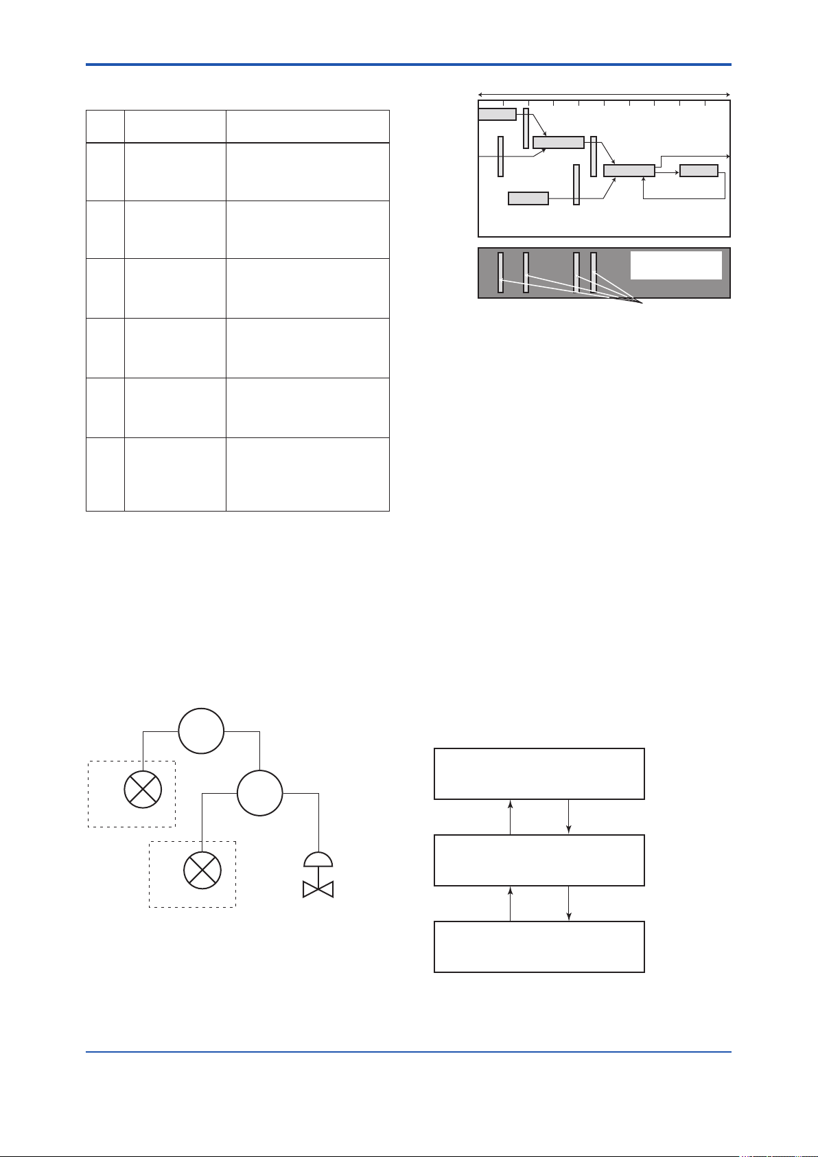
<5. Conguration>
5-3
Table 5.3 Execution Schedule of the EJX
Function Blocks
Index
269
MACROCYCLE_
(SM)
DURATION
Parameters
Setting (Enclosed is
factory-setting)
Cycle (MACROCYCLE)
period of control or
measurement. Unit is 1/32
ms. (16000 = 0.5 s)
276
(SM)
FB_START_
ENTRY.1
AI1 block startup time.
Elapsed time from the start of
MACROCYCLE specied in
1/32 ms. (0 = 0 s)
277
(SM)
FB_START_
ENTRY.2
AI2 block startup time.
Elapsed time from the start of
MACROCYCLE specified in
1/32 ms. (8000 = 250 ms)
278
(SM)
FB_START_
ENTRY.3
AI3 block startup time.
Elapsed time from the start of
MACROCYCLE specified in
1/32 ms. (16000 = 500 ms)
279
(SM)
FB_START_
ENTRY.4
AI4 block startup time.
Elapsed time from the start of
MACROCYCLE specified in
1/32 ms. (24000 = 750 ms)
280
to
289
(SM)
FB_START_
ENTRY.5
to
FB_START_
Not used.
ENTRY.14
Macrocycle (Control Period)
LI100
OUT
Commu-
nication
Schedule
IN
LIC100
BKCAL_IN
FI100
OUT
CAS_IN
FIC100
IN
BKCAL_IN
Unscheduled
Communication
BKCAL_OUT
FC100
BKCAL_OUT
Scheduled
Communication
F0503.ai
Figure 5.3 Function Block Schedule and
Communication Schedule
When the control period (macrocycle) is set to more
than 4 seconds, set the following intervals to be
more than 1% of the control period.
- Interval between “end of block execution” and
“start of sending CD from LAS”
- Interval between “end of block execution” and
“start of the next block execution”
A maximum of 30 ms is taken for execution of
AI block. For scheduling of communications for
combination with the next function block, the
execution is so arranged as to start after a lapse
of longer than 30 ms. In no case should function
blocks of the EJX be executed at the same time
(execution time is overlapped).
Figure 5.3 shows an example of schedule based on
the loop shown in Figure 5.2.
LIC100
EJX
#1
LI100
EJX
#2
FI100
Figure 5.2 Example of Loop Connecting
Function Block of Two EJX with Other
Instruments
FIC100
FC100
F0502.ai
5.4 Setting of Tags and Addresses
This section describes the steps in the procedure
to set PD Tags and node addresses in the EJX
multivariable transmitter. There are three states of
Fieldbus devices as shown in Figure 5.4, and if the
state is other than the lowest SM_OPERATIONAL
state, no function block is executed. EJX must be
transferred to this state when an EJX tag or address
is changed.
UNINITIALIZED
(No tag nor address is set)
Tag clear Tag setting
INITIALIZED
(Only tag is set)
Address clear
SM_OPERATIONAL
(Tag and address are retained, and
the function block can be executed.)
Figure 5.4 Status Transition by Setting PD Tag and
Node Address
Address setting
F0504.ai
IM 01C25R03-01E
Page 31

<5. Conguration>
5-4
EJX multivariable transmitter has a PD Tag
(FT2001) and node address (245, or hexadecimal
F5) that are set upon shipment from the factory
unless otherwise specied. To change only the
node address, clear the address once and then set
a new node address. To set the PD Tag, rst clear
the node address and clear the PD Tag, then set
the PD Tag and node address again.
Devices whose node addresses have been cleared
will have the default address (randomly chosen
from a range of 248 to 251, or from hexadecimal
F8 to FB). At the same time, it is necessary to
specify the device ID in order to correctly specify
the device. The device ID of the EJX multivariable
transmitter is 594543000Exxxxxxxx. (The xxxxxxxx
at the end of the above device ID is a total of 8
alphanumeric characters.)
5.5 Communication Setting
To set the communication function, it is necessary
to change the database residing in SM-VFD.
5.5.1 VCR Setting
Set VCR (Virtual Communication Relationship),
which species the called party for communication
and resources. EJX multivariable transmitter has 33
VCRs whose application can be changed, except
for the rst VCR, which is used for management.
EJX multivariable transmitter has VCRs of four
types:
Server(QUB) VCR
A Server responds to requests from a host. This
communication needs data exchange. This
type of communication is called QUB (Queued
User-triggered Bidirectional) VCR.
Source (QUU) VCR
A Source multicasts alarms or trends to other
devices. This type of communication is called
QUU (Queued User-triggered Unidirectional)
VCR.
Publisher (BNU) VCR
A Publisher multicasts block output to another
function block(s). This type of communication
is called BNU (Buffered Network-triggered
Unidirectional) VCR.
Subscriber (BNU) VCR
A Subscriber receives output of another
function block(s).
A Server VCR is capable to responding to
requests from a Client (QUB) VCR after the Client
successfully initiates connection to the Server. A
Source VCR transmits data without established
connection. A Sink (QUU) VCR on another device
can receive it if the Sink is congured so. A
Publisher VCR transmits data when LAS requests
so. An explicit connection is established from
Subscriber (BNU) VCR(s) so that a Subscriber
knows the format of published data.
Each VCR has the parameters listed in Table 5.4.
Parameters must be changed together for each
VCR because modication of individual parameters
may cause inconsistent operation.
Table 5.4 VCR Static Entry
Sub-
index
1 FasArTypeAndRole
2 FasDllLocalAddr
3 FasDllCongured
Parameter Description
Indicates the type and
role of communication
(VCR). The following 4
types are used for EJX.
0x32: Server
0x44: Source
0x66: Publisher (Sends
0x76: Subscriber
Sets the local address
to specify VCR in EJX.
A range of 20 to F7 in
hexadecimal.
Sets the node address
RemoteAddr
of the called party for
communication and
the address (DLSAP
or DLCEP) used to
specify VCR in that
address. For DLSAP or
DLCEP, a range of 20
to F7 in hexadecimal is
used.
Addresses in Subindex
2 and 3 need to be set
to the same contents of
the VCR as the called
party (local and remote
are reversed).
(Responds to
requests from
host.)
(Transmits alarm
or trend.)
block output to
other blocks.)
(Receives output
of other blocks.)
IM 01C25R03-01E
Page 32

<5. Conguration>
5-5
Sub-
index
4 FasDllSDAP
5 FasDllMaxConrm
6 FasDllMaxConrm
7 FasDllMaxDlsduSize
8 FasDllResidual
9 FasDllTimelinessClass Not used for EJX.
10 FasDllPublisherTime
11 FasDllPublisher
12 FasDllSubsriberTime
13 FasDllSubscriber
14 FmsVfdId
15 FmsMaxOutstanding
16 FmsMaxOutstanding
17 FmsFeatures
Parameter Description
Species the quality
of communication.
Usually, one of the
following types is set.
0x2B: Server
0x01: Source (Alert)
0x03: Source (Trend)
0x91: Publisher/
To establish connection
DelayOnConnect
DelayOnData
ActivitySupported
WindowSize
SynchronizaingDlcep
WindowSize
SynchronizationDlcep
ServiceCalling
ServiceCalled
Supported
for communication, a
maximum wait time
for the called party's
response is set in ms.
Typical value is 60
seconds (60000).
For request of data,
a maximum wait time
for the called party's
response is set in ms.
Typical value is 60
seconds (60000).
Species maximum DL
Service Data unit Size
(DLSDU). Set 256 for
Server and Trend VCR,
and 64 for other VCRs.
Species whether
connection is
monitored. Set TRUE
(0xff) for Server.
This parameter is
not used for other
communication.
Not used for EJX.
Not used for EJX.
Not used for EJX.
Not used for EJX.
Sets VFD for EJX to be
used.
0x1: System/network
0x1234: Function block
Set 0 to Server. It is
not used for other
applications.
Set 1 to Server. It is
not used for other
applications.
Indicates the type
of services in the
application layer. In the
EJX, it is automatically
set according to
specic applications.
Subscriber
management VFD
VFD
33 VCRs are factory-set as shown in the table
below.
Table 5.5 VCR List
Index
(SM)
293 1 For system management (Fixed)
294 2 Server (LocalAddr = 0xF3)
295 3 Server (LocalAddr = 0xF4)
296 4 Server (LocalAddr = 0xF7)
297 5 Trend Source (LocalAddr = 0x07,
298 6 Publisher for AI1 (LocalAddr = 0x20)
299 7 Alert Source (LocalAddr = 0x07,
300 8 Server (LocalAddr = 0xF9)
301 9 Publisher for AI2 (LocalAddr = 0x21)
302 to
315
VCR
Number
Remote Address=0x111)
Remote Address=0x110)
10 to 33 Not used.
Factory Setting
5.5.2 Function Block Execution Control
According to the instructions given in Section 5.3,
set the execution cycle of the function blocks and
schedule of execution.
5.6 Block Setting
Set the parameter for function block VFD.
5.6.1 Link Object
A link object combines the data voluntarily sent
by the function block with the VCR. The EJX
multivariable transmitter has 40 link objects. A
single link object species one combination. Each
link object has the parameters listed in Table 5.6.
Parameters must be changed together for each
VCR because the modications made to each
parameter may cause inconsistent operation.
IM 01C25R03-01E
Page 33

<5. Conguration>
5-6
Table 5.6 Link Object Parameters
Sub-
index
1 LocalIndex
Parameter Description
Sets the index of function
block parameters to be
combined; set “0” for Trend
and Alert.
2 VcrNumber
Sets the index of VCR to be
combined. If set to “0”, this
link object is not used.
3 RemoteIndex
4 ServiceOperation
Not used in EJX. Set to “0”.
Set one of the following.
Set only one each for link
object for Alert or Trend.
0: Undened
2: Publisher
3: Subscriber
6: Alert
7: Trend
5 StaleCountLimit
Set the maximum number
of consecutive stale input
values which may be
received before the input
status is set to BAD. To
avoid the unnecessary
mode transition caused
when the data is not
correctly received by
subscriber, set this
parameter to “2” or more.
Set link objects as shown in Table 5.7.
Table 5.8 Parameters for Trend Objects
Sub-
index
1 Block Index
Parameter Description
Sets the leading index of the
function block that takes a
trend.
2 Parameter
Relative
Index
Sets the index of parameters
taking a trend by a value
relative to the beginning of
the function block. In the EJX
AI block, the following three
types of trends are possible.
7: PV
8: OUT
19: FIELD_VAL
3 Sample Type
Species how trends are
taken. Choose one of the
following 2 types:
1: Sampled upon execution
of a function block.
2: The average value is
sampled.
4 Sample Interval
Species sampling intervals
in units of 1/32 ms. Set the
integer multiple of the function
block execution cycle.
5 Last Update
6 to 21List of Status
The last sampling time.
Status part of a sampled
parameter.
21 to 37List of Samples
Data part of a sampled
parameter.
Table 5.7 Factory-Settings of Link Objects
(example)
Index Link Object # Factory Settings
30000 1
30001 2
30002 3
30003 4
AI1.OUT → VCR#6
Trend → VCR#5
Alert → VCR#7
AI2.OUT → VCR#9
30004
to
5 to 40
Not used
30039
5.6.2 Trend Object
It is possible to set the parameter so that the
function block automatically transmits Trend. EJX
multivariable transmitter has seven Trend objects,
six of which are used for Trend in analog mode
parameters and one is used for Trend in discrete
mode parameter. A single Trend object species the
trend of one parameter.
Each Trend object has the parameters listed in
Table 5.8. The rst four parameters are the items
to be set. Before writing to a Trend object, it is
necessary to release the WRITE_LOCK parameter.
Seven trend objects are factory-set as shown Table
5.9.
Table 5.9 Trend Object are Factory-Set
Index Parameters Factory Settings
32000 to
32005
32006 TREND_DIS.1 Not used.
Link
object
EJX
DLSAP
DLCEP
Fieldbus Cable
Figure 5.5 Example of Default Conguration
TREND_FLT.1 to
TREND_FLT.5
SMIB
(System
Management
Information
Base)
NMIB
(Network
Management
Information
Base)
VCR
#1
0xF8 0xF3 0xF4 0xF7
Host 1 Host 2 Device 1 Device 2
Resource
block
FBOD
#2
Transducer
block
#3 #4
Not used.
AI1 OUT
#1 #2
#4
#8
#6
0xF9
AI2 OUT
Alert
#3
#7
#9
0x20 0x21
Trend
#5
0x07
F0505.ai
IM 01C25R03-01E
Page 34

<5. Conguration>
5-7
5.6.3 View Object
This object forms a group of parameters in a
block. One advantage brought by forming groups
of parameters is the reduction of load for data
transactions. View Object has the parameters
listed in Table 5.11 to 5.15. Purpose of View Objects
is shown in Table 5.10.
Table 5.10 Purpose of Each View Object
Description
VIEW_1
VIEW_2
VIEW_3
VIEW_4
Table 5.11 View Object for Resource Block
Relative
Index
Set of dynamic parameters required by
operator for plant operation. (PV, SV, OUT,
Mode etc.)
Set of static parameters which need to be
shown to plant operator at once. (Range etc.)
Set of all the dynamic parameters.
Set of static parameters for conguration or
maintenance.
Parameter Mnemonic
1 ST_REV 2 2 2 2
2 TAG_DESC
3 STRATEGY 2
4 ALERT_KEY 1
5 MODE_BLK 4 4
6 BLOCK_ERR 2 2
7 RS_STATE 1 1
8 TEST_RW
9 DD_RESOURCE
10 MANUFAC_ID 4
11 DEV_TYPE 2
12 DEV_REV 1
13 DD_REV 1
14 GRANT_DENY 2
15 HARD_TYPES 2
16 RESTART
17 FEATURES 2
18 FEATURE_SEL 2
19 CYCLE_TYPE 2
20 CYCLE_SEL 2
21 MIN_CYCLE_T 4
22 MEMORY_SIZE 2
23 NV_CYCLE_T 4
24 FREE_SPACE 4
25 FREE_TIME 4 4
1 2 3 4
VIEW
Relative
Index
Parameter Mnemonic
26 SHED_RCAS 4
27 SHED_ROUT 4
28 FAULT_STATE 1 1
29 SET_FSTATE
30 CLR_FSTATE
31 MAX_NOTIFY 1
32 LIM_NOTIFY 1
33 CONFIRM_TIME 4
34 WRITE_LOCK 1
35 UPDATE_EVT
36 BLOCK_ALM
37 ALARM_SUM 8 8
38 ACK_OPTION 2
39 WRITE_PRI 1
40 WRITE_ALM
41 ITK_VER 2
42 SOFT_REV
43 SOFT_DESC
44 SIM_ENABLE_MSG
45 DEVICE_STATUS_1 4
46 DEVICE_STATUS_2 4
47 DEVICE_STATUS_3 4
48 DEVICE_STATUS_4 4
49 DEVICE_STATUS_5 4
50 DEVICE_STATUS_6 4
51 DEVICE_STATUS_7 4
52 DEVICE_STATUS_8 4
SOFTDWN_
53
PROTECT
54 SOFTDWN_FORMAT 1
55 SOFTDWN_COUNT 2
SOFTDWN_ACT
56
_AREA
SOFTDWN_MOD
57
_REV
58 SOFTDWN_ERROR 2
Totals (# bytes) 22 30 73 35
1 2 3 4
VIEW
1
16
1
IM 01C25R03-01E
Page 35

<5. Conguration>
Table 5.12 View Object for SENSOR Transducer Block
Relative
Index
1 ST_REV 2 2 2 2 2 2 2 2 2 2 2
2 TAG_DESC
3 STRATEGY 2
4 ALERT_KEY 1
5 MODE_BLK 4 4
6 BLOCK_ERR 2 2
7 UPDATE_EVT
8 BLOCK_ALM
9 TRANSDUCER_DIRECTORY
10 TRANSDUCER_TYPE 2 2 2 2
11 XD_ERROR 1 1
12 COLLECTION_DIRECTORY
13 PRIMARY_VALUE_TYPE 2
14 PRIMARY_VALUE 5 5
15 PRIMARY_VALUE_RANGE 11
16 CAL_POINT_HI 4
17 CAL_POINT_LO 4
18 CAL_MIN_SPAN 4
19 CAL_UNIT 2
20 SENSOR_TYPE 2
21 SENSOR_RANGE 11
22 SENSOR_SN 32
23 SENSOR_CAL_METHOD 1
24 SENSOR_CAL_LOC 32
25 SENSOR_CAL_DATE 7
26 SENSOR_CAL_WHO 32
27 SENSOR_ISOLATOR_MTL 2
28 SENSOR_FILL_FLUID 2
29 SECONDARY_VALUE 5 5
30 SECONDARY_VALUE_UNIT 2
31 CAL_DEVIATION_HI 4
32 CAL_DEVIATION_LO 4
33 EXTERNAL_ZERO_TRIM 1
34 PRIMARY_VALUE_FTIME 4
35 TERTIARY_VALUE 5 5
36 SP_VALUE_TYPE 2
37 SP_VALUE_RANGE 11
38 CAL_SP_POINT_HI 4
39 CAL_SP_POINT_LO 4
40 CAL_SP_MIN_SPAN 4
41 CAL_SP_UNIT 2
42 CAL_SP_DEVIATION_HI 4
43 CAL_SP_DEVIATION_LO 4
44 SP_VALUE_FTIME 4
45 ATM_PRESS 4
46
CURRENT_ATM_PRESS_ENABLE
47
EXT_TEMP_VAL
48
EXT_TEMP_RANGE
49
CAL_EXT_TEMP_POINT_HI
50
CAL_EXT_TEMP_POINT_LO
51
CAL_EXT_TEMP_MIN_SPAN
52
CAL_EXT_TEMP_UNIT
53
CAL_EXT_TEMP_DEVIATION_HI
54
CAL_EXT_TEMP_DEVIATION_LO
55
EXT_TEMP_VALUE_FTIME
56
EXT_TEMP_OPTS
57
FIXED_EXT_TEMP_VALUE
58
SIMULATE_MODE
59
SIMULATE_DPRESS
60
SIMULATE_SPRESS
Parameter Mnemonic
1 2 3_1 3_2 3_3 3_4 4_1 4_2 4_3 4_4 4_5
1
5 5
4
4
4
4
4
2
4
1
5
5
VIEW
11
4
2
5-8
IM 01C25R03-01E
Page 36

<5. Conguration>
5-9
Relative
Index
61
62
63
64
65
66
67
68
69
70
71
72
73
74
75
76
77
78
79
80
81
82
83
84
85
86
87
88
89
90
91
92
93
94
95
96
97
98
99
100
101
102
103
104
105
106
107
108
109
110
111
112
113
114
115
116
117
118
119
120
Parameter Mnemonic
SIMULATE_ETEMP
EXT_TEMP_SENSOR_SN
CLEAR_CAL
CAP_TEMP_VAL
CAP_TEMP_RANGE
AMP_TEMP_VAL
AMP_TEMP_RANGE
MODEL
SPECIAL_ORDER_ID
MANUFAC_DATE
CAP_GASKET_MTL
FLANGE_MTL
D_VENT_PLUG
FLANGE_TYPE
REM_SEAL_ISOL_MTL
FLANGE_SIZE
REM_SEAL_NUM
REM_SEAL_FILL_FLUID
REM_SEAL_TYPE
ALARM_SUM
AUTO_RECOVERY
MS_CODE
DIAG_MODE
DIAG_PERIOD
DIAG_PRI
DIAG_ERR
DIAG_H_ALM
DIAG_L_ALM
DIAG_OPTION
REF_LIM_ FDPMIN
REF_LIM_ FSPMIN
REF_LIM_ BLKFMAX
COMP_FLAG
DIAG_LIM
DIAG_COUNT
REFERENCE_TIME
REFERENCE_FDP
REFERENCE_FSPL
REFERENCE_FSPH
REFERENCE_BLKF
REFERENCE_DPAVG
VALUE_TIME
VALUE_ FDP
VALUE_ FSPL
VALUE_ FSPH
VALUE_ BLKF
VALUE_DPAVG
RATIO_FDP
RATIO_FSPL
RATIO_FSPH
CRATIO_FDP
NRATIO_FDP
DIAG_APPLICABLE
FLG_TEMP_VAL
FLG_TEMP_RANGE
FLG_TEMP_COEF
FLG_TEMP_PRI
FLG_TEMP_H_LIM
FLG_TEMP_L_LIM
FLG_TEMP_ALM
VIEW
1 2 3_1 3_2 3_3 3_4 4_1 4_2 4_3 4_4 4_5
5
5 5
11
5 5
11
16
32
7
1
1
1
1
1
1
1
1
1
8 8
1
1
2
1
2
13
13
2
4
4
4
1
40
1
8
5
5
5
5
5
8
5
5
5
5
5
5
5
5
5
5
2
5
11
4
1
4
4
13
IM 01C25R03-01E
Page 37

<5. Conguration>
5-10
Relative
Index
121
122
123
124
125
126
127
128
129
130
131
132
133
134
135
136
137
138
139
TEST_KEY1
TEST_KEY2
TEST_KEY3
TEST1
TEST2
TEST3
TEST4
TEST5
TEST6
TEST7
TEST8
TEST9
TEST10
TEST11
TEST12
TEST13
TEST14
TEST15
TEST16
Totals (# bytes)
Parameter Mnemonic
1 2 3_1 3_2 3_3 3_4 4_1 4_2 4_3 4_4 4_5
49 82 101 32 108 103 99 106 77 95 26
Table 5.13 View Object for LCD Transducer Block
Relative
Index
1 ST_REV 2 2 2 2 2 2 2
2 TAG_DESC
3 STRATEGY 2
4 ALERT_KEY 1
5 MODE_BLK 4 4
6 BLOCK_ERR 2 2
7 UPDATE_EVT
8 BLOCK_ALM
9
10
11 XD_ERROR 1 1
12
13 DISPLAY_SEL 2
14 INFO_SEL 1
15 BLOCK_TAG1 32
16
17 DISPLAY_TAG1 8
18 UNIT_SEL1 1
19 DISPLAY_UNIT1 8
20 EXP_MODE1 1
21 BLOCK_TAG2 32
22
23 DISPLAY_TAG2 8
24 UNIT_SEL2 1
25 DISPLAY_UNIT2 8
Parameter
Mnemonic
TRANSDUCER_
DIRECTORY
TRANSDUCER_
TYPE
COLLECTION_
DIRECTORY
PARAMETER_
SEL1
PARAMETER_
SEL2
1 2 3_1 4_1 4_2 4_3 4_4
2 2 2 2
VIEW
2
2
VIEW
4
16
32
15
38
30
33
Relative
Index
26 EXP_MODE2 1
27 BLOCK_TAG3 32
28
29 DISPLAY_TAG3 8
30 UNIT_SEL3 1
31 DISPLAY_UNIT3 8
32 EXP_MODE3 1
33 BLOCK_TAG4 32
34
35 DISPLAY_TAG4 8
36 UNIT_SEL4 1
37 DISPLAY_UNIT4 8
38 EXP_MODE4 1
39
40 DISPLAY_CYCLE 1
41 TEST40 1
42
43
44
45
46
47
48
49
50
Parameter
Mnemonic
PARAMETER_
SEL3
PARAMETER_
SEL4
BAR_GRAPH_
SELECT
BLOCK_TAG5
PARAMETER_
SEL5
DISPLAY_TAG5
UNIT_SEL5
DISPLAY_UNIT5
EXP_MODE5
BLOCK_TAG6
PARAMETER_
SEL6
DISPLAY_TAG6
1 2 3_1 4_1 4_2 4_3 4_4
2
2
1
1
1
2
2
VIEW
2
2
32
2
8
1
8
1
32
2
8
IM 01C25R03-01E
Page 38

<5. Conguration>
5-11
Relative
Index
51
52
53
54
55
56
57
58
59
60
61
62
63
64
65
66
67
68
69
70
71
72
73
74
75
76
77
Parameter
Mnemonic
UNIT_SEL6
DISPLAY_UNIT6
EXP_MODE6
BLOCK_TAG7
PARAMETER_
SEL7
DISPLAY_TAG7
UNIT_SEL7
DISPLAY_UNIT7
EXP_MODE7
BLOCK_TAG8
PARAMETER_
SEL8
DISPLAY_TAG8
UNIT_SEL8
DISPLAY_UNIT8
EXP_MODE8
BLOCK_TAG9
PARAMETER_
SEL9
DISPLAY_TAG9
UNIT_SEL9
DISPLAY_UNIT9
EXP_MODE9
BLOCK_TAG10
PARAMETER_
SEL10
DISPLAY_TAG10
UNIT_SEL10
DISPLAY_UNIT10
EXP_MODE10
Totals (# bytes)
1 2 3_1 4_1 4_2 4_3 4_4
11 112 11 113 106 106 106
VIEW
1
8
1
32
2
8
1
8
1
32
2
8
1
8
1
32
32
Table 5.14 View Object for Flow Transducer Block
Relative
Index
1 ST_REV 2 2 2 2 2
2 TAG_DESC
3 STRATEGY 2
4 ALERT_KEY 1
5 MODE_BLK 4 4
6 BLOCK_ERR 2 2
7 UPDATE_EVT
8 BLOCK_ALM
9
10 TRANSDUCER_TYPE 2 2 2 2
Parameter Mnemonic
TRANSDUCER_
DIRECTORY
VIEW
1 2 3 4_1 4_2
Relative
Index
11 XD_ERROR 1 1
13
14
15
16
17
18
19
20
21
22
23
24
25
26
27
28
2
8
1
8
1
2
8
1
8
1
29
30
31
32
33
34
35
36
37 PIPE_DIAMETER 4
38 PIPE_EXPANSION_COEF 4
39 PIPE_REF_TEMPERATURE 4
40
41 FLOW_CONFIG1 20
42 FLOW_CONFIG2 12
43 FLOW_CONFIG3
44 FLOW_CONFIG4 16
45 CORRECTION_VALUE 32
46 CONFIG_SOFT_REV 16
47 CONFIG_DATE 16
48 CONFIG_WHO 32
49 CONFIG_STATUS 2
50 CONFIG_VSTRING32 32
51 CONFIG_VSTRING16 32
52 CONFIG_OSTRING32 32
53 CONFIG_OSTRING2 2
Parameter Mnemonic
FLOW_VALUE_TYPE
FLOW_VALUE
FLOW_VALUE_UNIT
FLOW_VALUE_DECIMAL
FLOW_VALUE_FTIME
DIFF_PRESSURE
DIFF_PRESSURE_UNIT
STATIC_PRESSURE
STATIC_PRESSURE_UNIT
EXT_TEMPERATURE
EXT_TEMPERAURE_UNIT
FLOW_CALCULATION_
MODE
FIXED_FLOW_VALUE
REF_STATIC_PRESSURE
REF_EXT_TEMPERATURE
TEMP_K1_FOR_LIQUID
FLUID_TYPE_CODE
ALARM_SUM
DENSITY_UNIT_CODE
LENGTH_UNIT_CODE
PRIMARY_DEVICE_CODE
PRIMARY_DEVICE_
DIAMETER
PRIMARY_DEVICE_
EXPANSION_COEF
PRIMARY_DEVICE_REF_
TEMPERATURE
BASE_DENSITY_FOR_
VOLUME_FLOW
Totals (# bytes) 39 98 71 92 100
VIEW
1 2 3 4_1 4_2
1
5 5
2
1
4
5 5
2
5 5
2
5 5
2
1
4
4
4
4
1
8 8
2
2
1
4
4
4
4
IM 01C25R03-01E
Page 39

<5. Conguration>
5-12
Table 5.15 View Object for AI Function Block
Relative
Index
Parameter Mnemonic
1 ST_REV 2 2 2 2
2 TAG_DESC
3 STRATEGY 2
4 ALERT_KEY 1
5 MODE_BLK 4 4
6 BLOCK_ERR 2 2
7 PV 5 5
8 OUT 5 5
9 SIMULATE
10 XD_SCALE 11
11 OUT_SCALE 11
12 GRANT_DENY 2
13 IO_OPTS 2
14 STATUS_OPTS 2
15 CHANNEL 2
16 L_TYPE 1
17 LOW_CUT 4
18 PV_FTIME 4
19 FIELD_VAL 5 5
20 UPDATE_EVT
21 BLOCK_ALM
22 ALARM_SUM 8 8
23 ACK_OPTION 2
24 ALARM_HYS 4
25 HI_HI_PRI 1
26 HI_HI_LIM 4
27 HI_PRI 1
28 HI_LIM 4
29 LO_PRI 1
30 LO_LIM 4
31 LO_LO_PRI 1
32 LO_LO_LIM 4
33 HI_HI_ALM
34 HI_ALM
35 LO_ALM
36 LO_LO_ALM
37 OUT_D_SEL 2
38 OUT_D 2
1 2 3 4
VIEW
Table 5.16 Indexes of View for Each Block
VIEW
1 2 3 4
Resourse Block 40100 40101 40102 40103
SENSOR Transducer
Block 40200 40201
FLOW Transducer
Block 40230 40231 40232
40202
to
40203
40204
to
40206
40233
to
40234
LCD Transducer Block
40250 40251 40252 40253
AI1 Function Block 40400 40401 40402 40403
AI2 Function Block 40410 40411 40412 40413
AI3 Function Block 40420 40421 40422 40423
AI4 Function Block 40430 40431 40432 40433
AI5 Function Block 40440 40441 40442 40443
PID Function Block 40800 40801 40802 40803
SC Function Block 41450 41451 41452 41453
IT Function Block 41600 41601 41602 41603
IS Function Block 41700 41701 41702 41703
AR Function Block 41750 41751 41752 41753
5.6.4 Function Block Parameters
Function block parameters can be read from the
host or can be set. For a list of the parameters of
blocks held by the EJX multivariable transmitter,
refer to “9.
PARAMETERS LISTS”. For the function blocks
other than AI block, LM function, software download
function and advanced diagnostic, refer to Appendix
1 to 8.
Totals (# bytes) 31 26 33 48
IM 01C25R03-01E
Page 40

<6. Explanation of Basic Items>
6. Explanation of Basic Items
6-1
6.1 Outline
This chapter describes the SENSOR transducer
block, the LCD transducer block, and the AI function
block and explains basic parameter settings.
Refer to Appendixes for other function blocks, LM
function, and software download function.
6.2 Setting and Changing Parameters for the Whole Process
IMPORTANT
Do not turn off the power immediately after
setting. When the parameters are saved to the
EEPROM, the redundant processing is executed
for an improvement of reliability. If the power
is turned off within 60 seconds after setting is
made, the modied parameters are not saved
and the settings may return to the original values.
Block mode
Many parameters require a change of the block
mode of the function block to O/S (Out of Service)
when their data is changed. To change the block
mode of the function block, its MODE_BLK needs
to be changed. The MODE_BLK is comprised of
the four sub-parameters below:
(1) Target (Target mode):
Sets the operating condition of the block.
(2) Actual (Actual mode):
Indicates the current operating condition.
(3) Permit (Permitted mode):
Indicates the operating condition that the
block is allowed to take.
(4) Normal (Normal mode):
Indicates the operating condition that the
block will usually take.
6.3 SENSOR Transducer Block
The SENSOR transducer block is in between the
sensor and the AI function blocks. It calculates
differential pressure, static pressure, external
temperature, and capsule temperature from sensor
signals. Then it performs damping and range
checks for the measured values of these three
variables and sends signals to the AI function block
and Flow transducer block. Figure 6.1 presents the
signal ow between blocks.
Sensor Transducer Block
PRIMARY_VALUE [DP]
(Channel1)
SECONDARY_VALUE [SP-H]
(Channel2)
TERITARY_VALUE [SP-L]
(Channel3)
EXT_TEMP_VAL
(Channel4)
CAP_TEMP_VAL
(Channel6)
AMP_TEMP_VAL
(Channel7)
FLG_TEMP_VAL
(Channel8)
Figure 6.1 Signal Flow Diagram
Flow Transducer Block
FLOW_VAL
(Channel5)
AI Function Block
CHANNEL=?
AI
AI
AI
AI
F0601.ai
IM 01C25R03-01E
Page 41

<6. Explanation of Basic Items>
6-2
6.3.1 Functional Block
Figure 6.2 presents the functional block of the
SENSOR transducer. The calculated values of
differential pressure, H-side static pressure, L-side
static pressure, external temperature, capsule
temperature, amplier temperature, and ange
temperature (option code: /DG1) are assigned
to PRIMARY_VALUE, SECONDARY_VALUE,
TERTIARY_VALUE, EXT_TEMP_VAL, CAP_
TEMP_VAL, AMP_TEMP_VAL, and FLG_TEMP_
VAL (option code: /DG1) respectively. Measured
values output to the AI function blocks are selected
by the Channel parameter of those blocks.
Simulation
value
Pressure
/differential
pressure
calculation
Range
check
Sensor
signals
RTD
signals
Static
pressure
calculation
External
temperature
calculation
Capsule
temperature
calculation
Amplifier
temperature
calculation
Flange
temperature
calculation
Range
check
Range
check
Range
check
Range
check
Range
check
Historical
records
Figure 6.2 SENSOR Transducer Functional Block
Adjust-
ment
Simulation
value
Adjust-
ment
Simulation
value
Adjust-
ment
Equipment
information
6.3.2 Block Mode
The Block modes permitted for the SENSOR
transducer block are Automatic (Auto) and Out of
Service (O/S). The mode must be set to Auto under
normal operating conditions, and to O/S when
making changes to an important parameter. For
parameters that can only be changed in the Auto
and O/S modes, refer to the parameter list for the
SENSOR Transducer block in Chapter 9.
Damping
processing
Damping
processing
Damping
processing
Unit
check
Unit
check
Unit
check
Unit
check
Unit
check
Unit
check
H-side
static
pressure
L-side
static
pressure
PRIMARY_VALUE
(Channel1)
SECONDARY_VALUE
(Channel2)
TERTIARY_VALUE
(Channel3)
EXT_TEMP_VAL
(Channel4)
CAP_TEMP_VAL
(Channel6)
AMP_TEMP_VAL
(Channel7)
FLG_TEMP_VAL
(Channel8)
F0602.ai
IM 01C25R03-01E
Page 42

<6. Explanation of Basic Items>
6-3
6.3.3 Functions Relating to Differential Pressure
Reference to differential pressure value:
By accessing PRIMARY_VALUE, it is possible to
refer to the differential pressure value and status.
The update period of this value is 200 mseconds.
The pressure unit is selected by XD_SCALE.
unit of the AI block, in which PRIMARY_VALUE is
selected. The status is normally Good-Non Specic.
However, in the case of a sensor failure or out of
measurement range, it turns to Bad or Uncertain.
For details, refer to Table 8.9.
Setting of signal damping for differential
pressure:
When the differential pressure signal uctuates
greatly, the uctuation can be reduced by increasing
the time constant for signal damping. PRIMARY_
VALUE_FTIME is the parameter for setting the
signal damping for differential pressure. The unit of
signal damping is second.
Determination of the range limit of differential
pressure signal:
When the differential pressure signal deviates more
than 10% from the capsule measurement range
shown in PRIMARY_VALUE_RANGE, set the
status of PRIMARY_VALUE to Uncertain-Sensor
Conversion not Accurate.
Adjustment of pressure/differential pressure
signal:
EJX multivariable transmitter have been accurately
adjusted according to the specications at factory
setting. Minimal errors can occur due to the
environment where the transmitter is installed and
the mounting position. To ne-tune any errors,
three zero/span adjustment functions can be used:
automatic and manual zero/span adjustment
by communication terminals, and zero-point
adjustment by means of the external adjustment
screw on the transmitter.
Automatic adjustment
The value of the pressure exerted on the point
where the adjustment is to be made is assigned
to parameters (CAL_POINT_LO, CAL_POINT_
HI). After this assignment is set, the amount of
adjustment is calculated by the transmitter and
automatically updated.
Manual adjustment
From the exerted pressure and the output of the
transmitter, calculate the amount of zero/span
adjustment manually, and assign the calculated
value to parameters (CAL_DEVIATION_LO,
CAL_DEVIATION_HI).
Zero-point adjustment by the external screw.
With pressure being exerted on the point where
the adjustment is to be made, zero adjustment
needs to be performed. To do this, adjust the
calculated value by turning the external Zero-point
adjustment screw, so that it agrees with the actual
input pressure (true value). The output value
increases when the screw is rotated to the right. It
decreases when the screw is rotated to the left. The
adjustment width is small when the rotation speed
is low and large when fast.
When performing zero-point adjustment by the
external screw, EXTERNAL_ZERO_TRIM needs to
be set to “Enable.”
Procedure for automatic adjustment
The procedure for automatic adjustment is as
follows:
(1) Change the Block mode
Set MODE_BLK to O/S.
(2) Enter zero% pressure
Apply the actual zero% pressure to EJX multivariable
transmitter.
(3) Perform zero adjustment
When the value of the applied pressure is written to
CAL_POINT_LO, EJX calculates the amount of
adjustment for zero adjustment. The calculated amount
of adjustment is incorporated into CAL_DEVIATION_LO.
(4) Input pressure for span adjustment
For span adjustment, apply the actual 100% pressure to
EJX multivariable transmitter.
(5) Performance of span adjustment
When the value of the applied pressure is written to
CAL_POINT_HI, EJX multivariable transmitter calculates
the amount of adjustment for span adjustment. The
calculated amount of adjustment is incorporated into
CAL_DEVIATION_HI.
(6) Change the operation mode
Set MODE_BLK to AUTO for normal operation.
F0603.ai
IM 01C25R03-01E
Page 43

<6. Explanation of Basic Items>
6-4
Calculated Value Calculated Value
After zero adjustment
0
Input pressure Input pressure
Before zero
adjustment
0
After zero/span
adjustment
Span
adjustmen
point
After zero
adjustment
F0604.ai
CAUTION
Span adjustment is a function for adjusting
the gradient with respect to the point of zero
adjustment. If that point is not zero, the gradient
of input and output values cannot be accurately
adjusted. Perform span adjustment after zero
adjustment is completed.
Diagnosis of adjustment results:
When the amount of zero adjustment or span
adjustment exceeds any of the following adjustment
limits, “AL50: Adjustment range error for differential
pressure” is displayed.
The conditions for zero/span adjustment are as
follows:
<1> The point of zero adjustment is within
±10% of the capsule range.
<2> The amount of zero adjustment is within
±10% of the capsule range.
<3> The point of span adjustment is within the
capsule range.
<4> The input and output gradients after span
adjustment are within ±10% of the gradient at
factory setting.
6.3.4 Functions Relating to Static Pressure
Reference to static pressure value:
In SECONDARY_VALUE and TERTIARY_VALUE,
it is possible to refer to the H-side static pressure
value and the L-side static pressure value,
respectively. The update period of these values
is 200 mseconds. The pressure unit is selected
by XD_SCALE.unit in the AI block, in which
SECONDARY_VALUE and TERTIARY_VALUE
are selected. The status is normally Good-Non
Specic. However, in the case of a sensor failure
or out of measurement range, it turns to Bad or
Uncertain. For specics, refer to Table 8.9.
Setting of signal damping for static pressure:
SP_VALUE_FTIME is parameter that set signal
damping for static pressure signals. The unit of the
signal damping is second.
Determination of the range limit of static
pressure signal:
When the static pressure signal exceeds the
maximum working pressure (MWP) of the capsule,
set the status of PRIMARY_VALUE to UncertainSubnormal. Also, set the status of SECONDARY_
VALUE and TERTIARY_VALUE to UncertainSensor Conversion not Accurate. The status under
normal conditions is Good-Non Specic.
Adjustment of static pressure signal:
The zero/span adjustment function can be used for
static signals, as in the case of differential pressure
signals. However, the zero-point adjustment by the
external screw function is not supported for static
pressure signal.
Automatic adjustment
The value of the static pressure exerted on the
point where adjustment is to be made is assigned
to parameters (CAL_SP_POINT_LO, CAL_SP_
POINT_HI). After this assignment is set, the amount
of adjustment is calculated by the transmitter and
automatically updated. The procedure for adjusting
the static pressure signal is the same as that of
differential pressure signal.
Manual adjustment
From the exerted pressure and the output of the
transmitter, calculate the amount of zero/span
adjustment manually and assign the calculated
value to parameters (CAL_SP_DEVIATION_LO,
CAL_SP_DEVIATION_HI).
Selection of static pressure signal type:
EJX910 multivariable transmitter measure the
absolute static pressure. Based on the assumption
that atmospheric pressure is constant, these
transmitters can output signal equivalent to gauge
pressure calculated by deducting the atmospheric
pressure (xed value) from the measured absolute
pressure. The type of static pressure signal output
to SECONDARY_VALUE and TERTIARY_VALUE
is selected in SP_VALUE_TYPE. SP_VALUE_
TYPE allows selection of gauge pressure or
absolute pressure. When selecting gauge pressure,
set the value of the atmospheric pressure (xed
value) to ATM_PRESS. The default value of
ATM_PRESS is equal to the value of standard
atmospheric pressure (101.325 kPa).
IM 01C25R03-01E
Page 44

<6. Explanation of Basic Items>
6-5
Atmospheric pressure automatic setting:
When “Set” is set to the CURRENT_ATM_PRESS_
ENABLE parameter, the present L-side static
pressure can be automatically assigned as the
atmospheric pressure (ATM_PRESS). To make
this assignment, the SENSOR transducer block
must be set to the O/S mode. After the L-side static
pressure has been assigned to ATM_PRESS,
the value of CURRENT_ATM_PRESS_ENABLE
automatically returns to “off.”
6.3.5 Functions Relating to External Temperature
Reference to external temperature value:
The contact temperature and status of the RTD
connected at EXT_TEMP_VAL can be referenced.
The update period of this value is about 800
mseconds. The external temperature unit is the unit
selected at XD_SCALE.Unit in the AI block where
EXT_TEMP_VAL is selected. Usually, the status
indicates Good-Non Specic; however, it changes
to Bad or Uncertain during a sensor malfunction or
when the measuring range is exceeded. For actual
details, see Table 8.9 Parameter Operations at
Error Occurrence.
Assignment of the damping time constant of the
external temperature signal:
The EXT_TEMP_VALUE_FTIME parameter is
for setting the damping parameter of the external
temperature signal. The setting unit for this
parameter is [seconds].
Judgment of range limit of the external
temperature signal:
When the external temperature signal has deviated
from the measuring range (-200 to 850°C) by 10°C
or more, it is outside the external temperature
specication range, and the status of the external
temperature signal (EXT_TEM_VAL) is set to
Uncertain-Sensor Conversion not Accurate.
procedure for adjusting the external temperature
signal is the same as that of the differential pressure
signal.
Manual adjustment
From the assigned temperature and the output
of the transmitter, calculate the amount of
zero/span adjustment manually and assign the
calculated value to parameters (CAL_EXT_
TEMP_DEVIATION_LO and CAL_EXT_TEMP_
DEVIATION_HI).
Diagnosis of adjustment:
When the adjustment amount exceeds the
following adjustment ranges, “AL52: Out of external
temperature span adjustment amount range/AL52:
Out of external temperature zero adjustment
amount range” generate an alarm. The zero/span
adjustment ranges are as follows:
(1) The ramp for the input/output of two
adjustment points must be within 10% of the
ramp set before shipment from the factory.
(2) The zero point adjustment amount must be
within ±85°C of the temperature set before
shipment from the factory.
(3) The zero point/span adjustment point must
be in the range -210°C to 860°C.
Fixed external temperature mode:
The value obtained from the external temperature
sensor or a user-specied xed value can be
selected for the external temperature signal. At
the EXT_TEMP_OPTS parameter, select one of
Selection 0 (No): External temperature sensor, 1
(Yes): External temperature xed value mode, and
2 (Fall Back): Fixed mode at broken wire.
When the external temperature xed mode or xed
mode at broken wire is selected, set the xed value
at FIXED_EXT_TEMP_VALUE.
6.3.6 Simulation Function
Adjustment of external temperature signal:
A zero/span adjustment function is available for the
external temperature signal just like for the pressure
(differential pressure) signal.
Automatic adjustment
The temperature value is assigned to parameters
(CAL_EXT_TEMP_LO and CAL_EXT_TEMP_HI)
with the external temperature sensor immersed
in the temperature to be adjusted. After this
assignment is made, the adjustment amount is
calculated internally by the transmitter and the
adjustment amount is automatically updated. The
There are two simulation functions in EJX
multivariable transmitter; one is the function
commonly offered in FOUNDATION Fieldbus products
to simulate input of each function block for loop
check, and the other is the ow simulation function
to simulate measured inputs for checking the result
of ow calculation.
The simulation function described in this section is
ow simulation function. For the other simulation
function, see ‘7.3 Simulation Function.’
IM 01C25R03-01E
Page 45

<6. Explanation of Basic Items>
A preset xed value can be output to the AI function
block or FLOW transducer block instead of the
differential pressure value, static pressure value
and external temperature value calculated from the
sensor signals.
Select the signal for enabling simulation in the
SIMULATE_MODE parameter. Set the value and
status to be used for simulation in the SIMULATE_
DPRESS, SIMULATE_SPRESS, and SIMULATE_
NOTE
If the DP or SP simulation value set by a user is
out of the setting range of the product(capsule),
the transmitter automatically use maximum or
minimum settable value in place of actual setting
value to perform simulation.
If the ET simulation value set by a user is out of
the setting range, a conguration error occurs.
ETEMP parameters.
6-6
Parameter Explanation
SIMULATE_
MODE
SIMULATE_
DPRESS
SIMULATE_
SPRESS
SIMULATE_
ETEMP
Select the signal for enabling simulation.
0= Simulation OFF
1= Differential pressure signal
simulation ON
2= Static pressure signal simulation ON
3= Differential pressure signal + static
pressure signal simulation ON
4= External temperature signal
simulation ON
5= Differential pressure signal +
external temperature signal simulation
ON
6= Static pressure signal + external
temperature signal simulation ON
7= Differential pressure signal +
static pressure signal + external
temperature signal simulation ON
15=Differential pressure signal +
static pressure signal + external
temperature signal (w/out damping
processing) simulation ON
Set the differential pressure signal
simulation value and status.
Set the static pressure signal simulation
value and status.
Set the external temperature signal
simulation value and status.
The ow value becomes the simulation value
which is calculated by using simulation value of
DP, SP and ET. The LCD continuously displays the
simulation value and alarm (AL.080 SNR.SIM) in
alternating sequence.
Simulation continues for 10 minutes, then is
released automaticaly.
If one of following alarm occurs, all the output data
is hold to the value before alarm occurs.
6.3.7 Functions Relating to Capsule and
Amplier Temperature
Reference to capsule and amplier temperature
value:
In CAP_TEMP_VAL and AMP_TEMP_VAL, it
is possible to refer to the capsule and amplier
temperature value and status. The update period
of this value is about 1 second. The temperature
unit is selected by XD_SCALE.unit of the AI block,
in which CAP_TEMP_VAL is selected. The status
is normally Good-Non Specic. However, in the
case of sensor failure or out of measurement range,
it turns to Bad or Uncertain. For specics, refer to
Table 8.9.
Determination of the range limit of capsule
temperature:
The range of capsule temperature is from -40 to
120°C. When the measured capsule temperature
deviates from -50 to 130°C range, set the status of
CAP_TEMP_VAL to Uncertain-Sensor Conversion
not Accurate. The status under normal conditions
is Good-Non Specic. Also, set the status of
PRIMARY_VALUE, SECONDARY_VALUE and
TERTIARY_VALUE TO Uncertain-Subnormal.
Determination of the range limit of amplier
temperature:
The range of amplier temperature is from -40 to
120°C. When the measured amplier temperature
deviates from -50 to 95°C range, set the status of
AMP_TEMP_VAL to Uncertain-Sensor Conversion
not Accurate. The status under normal conditions is
Good-Non Specic.
AL.01 (CAP. ERR)
AL.02 (AMP. ERR)
AL.03 (ET. ERR)
The simulation mode will automatically be released
after approximately ten minutes.
IM 01C25R03-01E
Page 46

<6. Explanation of Basic Items>
6-7
6.3.8 Functions Relating to Flange
Temperature (option code: /DG1)
Flange temperature value reference:
In FLG_TEMP_VAL, it is possible to refer to
the ange temperature value and status. The
update period of this value is about 1 second.
The temperature unit is selected by XD_SCALE.
unit of the AI block, in which FLG_TEMP_VAL is
selected. The status is normally Good-Non Specic.
However, it turns to Bad or Uncertain when sensor
failure happens. For specics, refer to Table
8.9. For details of Flange Temperature, refer to
APPENDIX 8.3.
6.3.9 BLOCK_ERR
BLOCK_ERR presents the cause of an error in the
block. The SENSOR transducer block checks the
following causes and sets the relevant bits.
BLOCK_ERR
Bit Error Cause
0 Other Differential pressure adjusted
by zero/span adjustment out
of measurement range, Static
pressure adjusted by zero/span
adjustment out of measurement
range Pressure sensor failure,
Capsule temperature sensor
failure Electronic circuit failure
15 Out of Service MODE_BLK.Target is O/S
6.3.10 XD_ERROR
XD_ERROR is a parameter that contains codes
for the most signicant errors that can occur in the
SENSOR transducer block. The errors of XD_
ERROR supported by EJX multivariable transmitter
and their causes are presented in the table below.
When multiple errors occur and their error codes
are different, the error with a larger code value is
stored rst.
XD_ERROR
Bit Error Cause
Out of Service Sensor TB is in O/S mode.
15
Calibration
18
error
Electronics
20
Failure
I/O Failure An I/O failure has occurred.
22
An error occurred during
calibration or a calibration error
has been detected.
An electronic component has
failed.
6.4 FLOW Transducer Block
6.4.1 Outline of the Functions
The differential pressure, static pressure and
external temperature signal calculated in the
SENSOR transducer block are input to this block,
and the ow calculation is performed based
on these signals. The result undergoes output
processing (e.g. damping), and the ow signal is
output to the AI function block.
6.4.2 Block Mode
The Block modes permitted for the FLOW
transducer block are Automatic (Auto) and Out
of Service (O/S). Note that the Automatic mode
cannot be set when option code A (Multi Sensing) is
selected in the measurement function.
For normal operation, select the Automatic mode.
To change important parameters, the O/S mode
must be selected. For details on how to identify
parameters that can be changed in the Automatic
mode and parameters that can be changed only in
the O/S mode, see chapter 9. Parameter Lists.
6.4.3 Calculation of the Flow
The calculated ow value and status are stored
to the FLOW_VALUE parameter. For details
on the ow calculation, refer to EJX910A and
EJX930A Multivariable Transmitters User's Manual
(IM 01C25R01-01E). The update period of the
ow calculation is 200 mseconds, and the ow
calculation is not updated when the operation mode
is O/S. Note that the Automatic mode cannot be
set when option code A (Multi Sensing) is selected
in the measurement function. There are two ow
calculation modes: Auto Compensation mode and
Basic mode. When ow calculation is performed
in the Auto Compensation mode, the calculation
coefcient must be calculated by the dedicated
setup tool and downloaded to the transmitter. For
details on this method, refer to the User's Manual
(IM 01C25R51-01E) for the dedicated setup tool.
The procedure for setting the BASIC Mode is as
follows. For details on how to calculate the Kfactor,
refer to the EJX910A and EJX930A Multivariable
Transmitters User's Manual (IM 01C25R01-01E).
IM 01C25R03-01E
Page 47

<6. Explanation of Basic Items>
6-8
BASIC Mode Setting Procedure
(1) Set the operation mode to O/S.
(2) Select easy ow calculation at FLOW_
CALCULATION_MODE.
(3) Select the uid code (liquid or gas) at
FLUID_TYPE_CODE.
(4) Select the ow equation in the following
table from the uid type (liquid/gas) and ow
unit category (mass ow/standard volume
ow/volume ow).
Fluid
type
Liquid Mass Flow
Gas Mass Flow
*1 Custom setting Parameter
Flow unit
Category
Normal-Standard
Volume Flow
Volume Flow
Normal-Standard
Volume Flow
Volume Flow
Flow equation
Qm or Qv or Qv norm
=Kfactor
× ∆P×(1+Temp K1×(T-Tb))
Qm or Qv norm
=Kfactor
× ∆P×Tb/T×SP/SPb
Qv=Kfactor
× ∆P×T/Tb×SPb/SP
T0601.ai
*1
*1
*1
(5) Set the required data (values marked by
==== in the above table) to the following
parameters.
• Kfactor → FIXED_FLOW_VALUE
• Temp K1 → TEMP_K1_FOR_LIQUID
• Tb → REF_EXT_TEMP_TERATURE
• SPb → REF_STATIC_PRESSURE
(6) Set the operation mode to AUTO.
NOTE
To conrm the setting of ow calculation, use
Simulation Function. See ‘6.3.6 Simulation
Function.’
6.4.4 Flow Unit/Decimal Point Digit
The ow unit is indicated in the FLOW_VALUE_
UNIT parameter and the number of digits past
the ow decimal point is indicated in the FLOW_
VALUE_DECIMAL parameter. As the content
of these parameters is interlocked with sub
parameters Unit and Decimal of XD_SCALE in the
AI function block where the ow signal is selected,
FLOW_VALUE_UNIT and FLOW_VALUE_
DECIMAL also are automatically changed when
XD_SCALE.Unit and XD_SCALE.Decimal are
changed.
6.4.5 Flow Type Selection
Mass ow, volume ow and standard volume
ow are automatically selected according to the
ow unit. The currently selected ow type can be
referenced at the FLOW_VALUE_TYPE parameter.
6.4.6 BLOCK_ERR
The BLOCK_ERR parameter indicates the cause
of errors that occur in the block. On the FLOW
transducer block, check the following error causes,
and set the bit corresponding to the cause.
Measurement function
Bit Name
Multi Sensing
0 Other Setting error*1Compensation
15 Out of
Not supported O/S is set for ModeBLK.
Service
*1: The mode other than O/S is set for ModeBLK.Target.
*2: The ow value is zero or less. This is supported only in the
Auto Compensation mode.
*3: The sum value of the Auto Compensation ow setting
does not agree with the value when it was written by the
setup tool.
Mass Flow
Measurement
coefcient setting error
Precision ow setting
3
checksum error
*
Target.
*2
6.4.7 XD_ERROR
The XD_ERROR parameter indicates the most
important error code among the errors that are
currently occurring on the FLOW transducer block.
The following table summarizes the content of
supported XD_ERRORs and error codes.
When two or more error codes are being generated
simultaneously, error codes are displayed with
preference given to the largest error code.
Error
Error Name Description
Code
15 Out of
Service
19 Conguration
error
23 Data Integrity
Error
15 Algorithm
Error
FLOW TB is in the
O/S mode.
Other than O/S is
set even though it
is a Multi Sensing
type.
The ow setting
sum value does
not agree with
the value when it
was written by the
setup tool.
The ow value is
smaller than zero.
Multi
Setting
—
—
—
Support
Mass Flow
Measurement
—
IM 01C25R03-01E
Page 48

<6. Explanation of Basic Items>
6-9
6.5 LCD Transducer Block
6.5.1 Outline of the Functions
The LCD transducer block controls alarms and
measured values that are displayed on the integral
indicator. It displays not only OUT signals from the
AI blocks, but also I/O signals of the Installed blocks
on the integral indicator.
6.5.2 Block Mode
The Block modes permitted for the LCD transducer
block are Automatic (Auto) and Out of Service (O/
S). Settings can be changed in the AUTO mode for
this block, except the Block tag parameter.
6.5.3 Display Contents of the Integral
Indicator
The components of the integral indicator are the bar
graph, the title eld, the center eld for numerical
values, the lower text eld, and auxiliary characters.
The contents and meanings of these components
are as follows:
40.000
Component
name
Bar graph Shows the value displayed in the center
eld for numerical values scaled in terms
of percentage.
Center eld
for numerical
values
Lower text
eld
Title eld Depicts the type of the value displayed
Auxiliary
characters
Presents values of inputs and outputs.
While the alarm is on, the alarm number
alternates with the displayed value here.
Displays tag, parameter name, unit, and
signal status. While the alarm is on, the
alarm contents alternate.
on the center eld for numerical value.
P Flashes when differential
SP Flashes when static pressure is
T Flashes when temperature is
F Flashes when ow rate is
% Flashes when the center eld
Key
mark
×10,
×100,
×1000
Contents
pressure is displayed.
displayed.
displayed.
displayed.
for numerical values displays a
% value.
Flashes when square root
display is selected.
Flashes when Write Protect is
selected.
Used when the calculated value
displayed in the center eld for
numerical values is rounded.
37.000
F0605.ai
Figure 6.3 Screen Display of the integral indicator
IM 01C25R03-01E
Page 49

<6. Explanation of Basic Items>
6.5.4 Example Displays of the Integral Indicator
Example display of AI1 OUT and PID FF_VAL, respectively
Display of
AI1 OUT
6-10
(1) Pressure Value
Block tag
(5) Pressure Value
Block tag
(2) Pressure Value
Parameter name
(6) Pressure Value
Parameter name
(3) Pressure Value
Unit
(7) Pressure Value
Unit
Example display during mechanical failure alarm
Alarm number and
Error Massage (Capsule error)
(4) Pressure Value
Status
Display of
PID FFVAL
(8) Pressure Value
Status
F0606.ai
IM 01C25R03-01E
Page 50

<6. Explanation of Basic Items>
6.5.5 Procedure to Set the Built-in Display
6-11
Select from Parameter Displays (1 to 10)
Select items to be displayed in the lower
Specify parameters to be displayed
Set the display contents for the block tag to be
Select whether the unit to be displayed in the
automatic or on a customized basis
AUTO is
selected
(DISPLAY_SEL)
text field (INFO_SEL)
(PARAMETER_SEL)
displayed in the lower text field
(DISPLAY_TAG)
lower text field should be set to
(UNIT_SEL)
CUSTOM is
selected
Set the display contents
of the unit
(DISPLAY_UNIT)
Specify which DISPLAY# to display.
(#: 1 to 10)
Specify whether tag, parameter, unit, or status
should be displayed.
Select parameters to be displayed from
PARAMETER_SEL listed in Table 6.1.
Written as by 6 characters or 6 characters plus “/”,“.”.
The display selected by
DISPLAY_SEL needs to
be set
Written as by 6 characters or 6 characters plus “/”,“.”.
English alphabetic characters, numeric characters from 0
through 9, /(slash) and .(dot) can be used to define the
unit. If characters other than above are specified, blank
space will be displayed on LCD for those characters.
Set an exponent (EXP_MODE)
Perform ON/OFF setting of the bar graph
(BAR_GRAPH_SELECT)
Set the display period
(DISPLAY_CYCLE)
Figure 6.4 Procedures to Set the Built-in Display
Example display of exponent setting:
The LCD value for exponent setting when the actual pressure
value is 23.4568 kPa and the decimal point selected is 2.
Corresponding
decimal point
2
2
2
2
Time unit: 800 mseconds; When the value set is “3”, the
same display continues for about 2.4 seconds.
Exponent
Engineering Unit
Eng. Unit @ 1/10
Eng. Unit @ 1/100
Eng. Unit @ 1/1000
LCD value
(kPa)
23.46
2.35
0.23
0.02
F0607.ai
IM 01C25R03-01E
Page 51

<6. Explanation of Basic Items>
Table 6.1 Parameters to be displayed on LCD
Block Name Parameter PARAMETER_SEL Display
SENSOR TRANSDUCER PRIMARY_VALUE PRIMARY VALUE PV
SECONDARY_VALUE SECONDARY VALUE SP.HI
TERTIARY_VALUE TERTIARY VALUE SP.LO
EXT_TEMP_VAL EXT TMP VALUE EXT.TMP
CAP_TEMP_VAL CAP TEMP VALUE CAP.TMP
AMP_TEMP_VAL AMP TEMP VALUE AMP.TMP
FLG_TEMP_VAL* FLG TEMP VALUE FLG.TMP
FLOW TRANSDUCER FLOW_VALUE FLOW VALUE FLOW
AI1 PV AI1 PV PV
OUT AI1 OUT OUT
FIELD_VAL AI1 FIELD VAL FLD.VAL
AI2 PV AI2 PV PV
OUT AI2 OUT OUT
FIELD_VAL AI2 FIELD VAL FLD.VAL
AI3 PV AI3 PV PV
OUT AI3 OUT OUT
FIELD_VAL AI3 FIELD VAL FLD.VAL
AI4 PV AI4 PV PV
OUT AI4 OUT OUT
FIELD_VAL AI4 FIELD VAL FLD.VAL
AI5 PV AI5 PV PV
OUT AI5 OUT OUT
FIELD_VAL AI5 FIELD VAL FLD.VAL
PID SP PID SP SP
PV PID PV PV
OUT PID OUT OUT
IN PID IN IN
CAS_IN PID CAS IN CAS.IN
BKCAL_IN PID BKCAL IN BKC.IN
BKCAL_OUT PID BKCAL OUT BKC.OUT
RCAS_IN PID RCAS IN RCAS.IN
ROUT_IN PID ROUT IN ROUT.IN
RCAS_OUT PID RCAS OUT RCA.OUT
ROUT_OUT PID ROUT OUT ROU.OUT
FF_VAL PID FF VAL FF.VAL
TRK_VAL PID TRK VAL TRK.VAL
AR OUT AR OUT OUT
IN AR IN IN
IN_LO AR IN LO IN.LO
IN1 AR IN 1 IN1
IN2 AR IN 2 IN2
IN3 AR IN 3 IN3
IT OUT IT OUT OUT
IN1 IT IN 1 IN1
IN2 IT IN 2 IN2
SC OUT_1 SC OUT 1 OUT.1
OUT_2 SC OUT 2 OUT.2
IN_1 SC IN 1 IN1
IN_2 SC IN 2 IN2
6-12
IM 01C25R03-01E
Page 52

<6. Explanation of Basic Items>
Block Name Parameter PARAMETER_SEL Display
IS OUT IS OUT OUT
IN_1 IS IN 1 IN1
IN_2 IS IN 2 IN2
IN_3 IS IN 3 IN3
IN_4 IS IN 4 IN4
IN_5 IS IN 5 IN5
IN_6 IS IN 6 IN6
IN_7 IS IN 7 IN7
IN_8 IS IN 8 IN8
*: The ange temperature is not calculated without option code /DG1, so that 0 is displayed.
6.5.6 Units That Can Be Displayed on the LCD by the Automatic Link Function
Index Unit Display on the LCD
1000 K K
1001 °C deg C
1002 °F deg F
1130 Pa Pa
1131 GPa GPa
1132 MPa MPa
1133 kPa kPa
1134 mPa mPa
1135 µPa uPa
1136 hPa hPa
1137 bar bar
1138 mbar mbar
1139 torr torr
1140 atm atm
1141 psi psi
1142 psia psia
1143 psig psig
1144 g/cm
1145 kg/cm
1146 inH2O inH2O
1147 inH2O(4°C) inH2O
1148 inH2O(68°F) inH2O
1149 mmH2O mmH2O
1150 mmH2O(4°C) mmH2O
1151 mmH2O(68°F) mmH2O
1152 ftH2O ftH2O
1153 ftH2O(4°C) ftH2O
1154 ftH2O(68°F) ftH2O
1155 inHg inHg
1156 inHg(0°C) inHg
1157 mmHg mmHg
1158 mmHg(0°C) mmHg
1318 g/s g/s
1319 g/min g/m
1320 g/h g/h
1322 kg/s kg/s
1323 kg/min kg/m
1324 kg/h kg/h
1325 kg/d kg/d
2
2
g/cm2
kg/cm2
Index Unit Display on the LCD
1327 t/min t/m
1328 t/h t/h
1329 t/d t/d
1330 lb/s lb/s
1331 lb/min lb/m
1332 lb/h lb/h
1333 lb/d lb/d
1335 STon/min STon/m
1336 STon/h STon/h
1337 STon/d STon/d
1340 LTon/h LTon/h
1341 LTon/d LTon/d
1347 m3/s m3/s
1348 m3/min m3/m
1349 m3/h m3/h
1350 m3/d m3/d
1351 L/s L/s
1352 L/min L/m
1353 L/h L/h
1355 ML/d ML/d
1356 CFS CFS
1357 CFM CFM
1358 CFH CFH
1359 ft3/d ft3/d
1360 SCFM SCFM
1361 SCFH SCFH
1362 gal/s gal/s
1363 GPM GPM
1364 gal/h gal/h
1365 gal/d gal/d
1366 Mgal/d Mgal/d
1367 ImpGal/s IGal/s
1368 ImpGal/min IGal/m
1369 ImpGal/h IGal/h
1370 ImpGal/d IGal/d
1371 bbl/s bbl/s
1372 bbl/min bbl/m
1373 bbl/h bbl/h
1374 bbl/d bbl/d
6-13
IM 01C25R03-01E
Page 53

<6. Explanation of Basic Items>
6-14
Index Unit Display on the LCD
1524 Nm3/h Nm3/h
1525 Nm3/d Nm3/d
1529 Sm3/h Sm3/h
1530 Sm3/d Sm3/d
1534 NL/h NL/h
1537 SL/s SL/s
1538 SL/min SL/min
1539 SL/h SL/h
1541 Paa Paa
1542 Pag Pag
1543 GPaa GPaa
1544 GPag GPag
1545 MPaa MPaa
1546 MPag MPag
1547 kPaa kPaa
1548 kPag kPag
1549 mPaa mPaa
1550 mPag mPag
1551 µPaa uPaa
1552 µPag uPag
1553 hPaa hPaa
1554 hPag hPag
1555 g/cm2a g/cm2a
1556 g/cm2g g/cm2g
1557 kg/cm2a kg/cm2a
1558 kg/cm2g kg/cm2g
1559 inH2Oa inH2Oa
1560 inH2Og inH2Og
1561 inH2Oa(4°C) inH2Oa
1562 inH2Og(4°C) inH2Og
1563 inH2Oa(68°F) inH2Oa
1564 inH2Og(68°F) inH2Og
1565 mmH2Oa mmH2Oa
1566 mmH2Og mmH2Og
1567 mmH2Oa(4°C) mmH2Oa
1568 mmH2Og(4°C) mmH2Og
1569 mmH2Oa(68°F) mmH2Oa
1570 mmH2Og(68°F) mmH2Og
1571 ftH2Oa ftH2Oa
1572 ftH2Og ftH2Og
1573 ftH2Oa(4°C) ftH2Oa
1574 ftH2Og(4°C) ftH2Og
1575 ftH2Oa(68°F) ftH2Oa
1576 ftH2Og(68°F) ftH2Og
1577 inHga inHga
1578 inHgg inHgg
1579 inHga(0°C) inHga
1580 inHgg(0°C) inHgg
1581 mmHga mmHga
1582 mmHgg mmHgg
1583 mmHga(0°C) mmHga
1584 mmHgg(0°C) mmHgg
1590 barg Barg
1591 mbarg mBarg
Index Unit Display on the LCD
1597 bara Bara
1598 MSCFD MSCFD
1599 MMSCFD MMSCFD
65520 SCFS SCFS
65521 SCFD SCFD
6.6 AI Function Block
The AI function block is a unit of the software and
executed according to the system schedule. During
execution, it incorporates data from the SENSOR
and Flow transducer block. After execution, it
updates analog outputs and processes newly
generated alarms. AI function blocks can provide
a discrete output which shows the status of LO,
LO_LO, HI, or HI_HI. In terms of function, there is
no difference between the ve AI function blocks
provided in EJX multivariable transmitter.
6.6.1 Function Blocks
The AI function block, via the Channel, incorporates
analog signals from the transducer block, performs
scaling processing, ltering, low-cut, and alarm
processing before outputting. It has the function to
generate a discrete output. Figure 6.5 presents the
AI function block.
IM 01C25R03-01E
Page 54

<6. Explanation of Basic Items>
6-15
OUT_D_SEL
Simulate
SIMULATE.
Transducer Value
Disable Enable
Simulate
SIMULATE.
Simulate Value
SIMULATE.Enable
FIELD_VAL.Value
Scaling
XD_SCALE
/100
/100
L_TYPE
Ind.Sqr Root
Scaling
OUT_SCALE
Indirect
Figure 6.5 Diagram of the AI Functional Block
6.6.2 Block Mode
The Block modes permitted for the AI function
block are Automatic (Auto), Manual (Man), and
Out of Service (O/S). When the Block mode of RB
(Resource Block) is Out of Service (O/S), Actual
is Out of Service (O/S) even if Automatic (Auto) or
Manual (Man) is written to Target.
Direct
Alarms
Filter
PV_FTIME
IO_OPTS.Low cutoff
=1(Enable)
Cutoff
LOW_CUT
=0(Disable)
LO, LO_LO
HI, HI_HI
PV.Value
Auto
OUT
MODE_BLK.Actual
OUT_D
6.6.5 OUT_D
OUT_D.value is “1” when the alarms selected by
OUT_D_SEL occur.
OUT_D.status is linked OUT.status. OUT_D.value
can be written the value form 0 to 15 when block
mode is O/S or MAN mode. The OUT_D_SEL
options are shown below.
F0608.ai
6.6.3 IO_OPTS
IO_OPTS is a parameter used to select whether
options regarding input and output signals should
be enabled or disabled. In the case of the AI
function block, the only available option is “Low
cutoff”. When enabling the low cut function for
outputs, set this option.
6.6.4 STATUS_OPT
STATUS_OPT is a parameter to select options
regarding the status of signals. The AI function
block offers four options: Propagate Fault Forward,
Uncertain if Limited, BAD if Limited, and Uncertain if
Man mode.
Propagate Fault Forward
If the status from the sensor is Bad, Device failure
or Bad, Sensor failure, propagate it to OUT without
generating an alarm. The use of these sub-statuses
in OUT is determined by this option. Through this
option, the user may determine whether alarming
(sending of an alert) will be done by the block or
propagated downstream for alarming.
High High Alarm (1):
OUT_D.value will be “1” when HI_HI alarm
occurs.
High Alarm (2):
OUT_D.value will be “1” when HI alarm
occurs.
Low Low Alarm (4):
OUT_D.value will be “1” when LO_LO alarm
occurs.
Low Alarm (8):
OUT_D.value will be “1” when LO alarm
occurs.
Uncertain if Man mode
When the “Uncertain if Man” is enabled and the
Actual mode is Man, the OUT signal status should
be “Uncertain”.
IM 01C25R03-01E
Page 55

<6. Explanation of Basic Items>
ALARM_OPTS=HI_HI | HI | LO_LO
(A case of HI_HI, HI and LO_LO options are selected)
HI_HI_LIM
HI_LIM
OUT_D.value = 0
LO_LO_
LIM
6-16
OUT_D.value = 1
OUT_D.value = 1 OUT_D.value = 1
OUT_D.value = 1
F0609.ai
Figure 6.6 An Example of OUT_D.value
6.6.6 Basic Parameters of the AI Block.
Parameter Outline
OUT Shows output value and status. When the Block mode is Man and O/S, the value is held.
SIMULATE Used for simulation. It sets the value and status arbitrarily from the transducer. Use this parameter for
loop checking. Refer to 7.3 Simulation Function.
XD_SCALE Sets the range of inputs from the transducer block that corresponds to 0% and 100% in the AI function
block. Also sets the unit of the range, inputs values that correspond to 0% and 100%, and four decimal
values.
OUT_SCALE Sets the range, unit, and digit of the output scale.
CHANNEL Selects the signal which is calculated in SENSOR Transducer Block. The relation between the signals
and channels are shown below;
Channel 1: PRIMARY_VALUE (pressure/differential pressure)
Channel 2: SECONDARY_VALUE (H-side static pressure)
Channel 3: TERTIARY_VALUE (L-side static pressure)
Channel 4: EXT_TEMP_VALUE(external temperature)
Channel 5: FLOW_VALUE(ow)
Channel 6: CAP_TEMP_VAL (capsule temperature)
Channel 7: AMP_TEMP_VAL (amplier temperature)
Channel 8: FLG_TEMP_VAL (ange temperature, option code: /DG1)
Flow value(channel 5) can be assigned to only one AI block at one time.
Other variables can be assigned to one or more AI blocks simultaneously.
L_TYPE The operation function of the AI function block can be selected from Direct, Indirect Linear, or Indirect
SQRT:
Direct: The Signal from the transducer block is directly output by ltering only, but without scaling or
square root extraction.
Indirect Linear: Values scaled according to the range settings of XD_SCALE and OUT_SCALE are
output.
Indirect SQRT: The square root extraction is performed to the values scaled according to the range
settings of XD_SCALE. The square root values are scaled and output according to the range settings
of OUT_SCALE.
LOW_CUT When the output value is smaller than the value set by this parameter, the output value is 0. To enable
the low-cut function, this parameter must be enabled in IO_OPTS. The setting is in an engineering unit of
OUT_SCALE. 1% of OUT_SCALE is applied as hysteresis.
IM 01C25R03-01E
Page 56

<7. In-Process Operation>
7. In-Process Operation
7-1
This chapter describes the procedure performed
when changing the operation of the function block
of the EJX multivariable transmitter in process.
7.1 Mode Transition
When the function block mode is changed to
Out_Of_Service, the function block pauses and a
block alarm is issued.
When the function block mode is changed to
Manual, the function block suspends updating of
output values. In this case alone, it is possible to
write a value to the OUT parameter of the block
for output. Note that no parameter status can be
changed
7.2 Generation of Alarm
7.2.1 Indication of Alarm
When the self-diagnostics function indicates that a
device is faulty, an alarm (device alarm) is issued
from the resource block. When an error (block
error) is detected in each function block or an error
in the process value (process alarm) is detected, an
alarm is issued from each block. If an LCD indicator
is installed, the error number is displayed as AL.XX.
If two or more alarms are issued, multiple error
numbers are displayed.
For details of ALARM, refer to Section 8.2
F0701.ai
Figure 7.1 Error Identication on Indicator
7.2.2 Alarms and Events
The following alarms or events can be reported by
the EJX multivariable transmitter if Link object and
VCR static entry are set.
Analog Alerts (Generated when a process value
exceeds threshold)
By AI Block Hi-Hi Alarm, Hi Alarm, Low Alarm,
Low-Low Alarm
Discret Alerts (Generated when an abnormal
condition is detected)
By Resource Block Block Alarm, Write Alarm
By Transducer Block Block Alarm,
Diagnostic Alarm(option code: /DG1)
By AI, SC, IT, IS, AR and PID Blocks
Block Alarm
Update Alerts (Generated when an important
(restorable) parameter is updated)
By Resource Block Update Event
By Transducer Block Update Event
By AI, SC, IT, IS, AR and PID Blocks
Update Event
An alert has following structure:
Table 7.1 Alert Object
Subindex
Parameter
Name
Analog
Alert
Discrete
Alert
Update
Alert
1 1 1 Block
Index
2 2 2 Alert Key Alert Key copied from the
3 3 3 Standard
Type
4 4 4 Mfr Type Alert Name identied by
5 5 5 Message
Type
6 6 6 Priority Priority of the alarm
7 7 7 Time
Stamp
8 8 Subcode Enumerated cause of this
9 9 Value Value of referenced data
10 10 Relative
Index
8 Static
Revision
11 11 9 Unit Index Unit code of referenced
Explanation
Index of block from which
alert is generated
block
Type of the alert
manufacturer specic DD
Reason of alert
notication
Time when this alert is
rst detected
alert
Relative index of
referenced data
Value of static revision
(ST_REV) of the block
data
IM 01C25R03-01E
Page 57

<7. In-Process Operation>
7-2
7.3 Simulation Function
There are two simulation functions in EJX
multivariable transmitter; one is the function
commonly offered in FOUNDATION Fieldbus products
to simulate input of each function block for loop
check, and the other is the ow simulation function
to simulate measured inputs for checking the result
of ow calculation.
The simulation function described in this section is
the former one. For ow simulation function, see
‘6.3.6 Simulation Function.’
The simulation function simulates the input of a
function block and lets it operate as if the data was
received from the transducer block. It is possible to
conduct testing for the downstream function blocks
or alarm processes.
A SIMULATE_ENABLE switch is mounted in the
amplier. This is to prevent the accidental operation
of this function. When this is switched on, simulation
is enabled. (See Figure 7.2.) To initiate the same
action from a remote terminal, if REMOTE LOOP
TEST SWITCH is written to the SIM_ENABLE_
MSG parameter (index 1044) of the resource block,
the resulting action is the same as is taken when
the above switch is on. Note that this parameter
value is lost when the power is turned OFF. In
simulation enabled status, an alarm is generated
from the resource block, and other device alarms
will be masked; for this reason the simulation must
be disabled immediately after using this function.
When Simulate En/Disable in Table 7.2 above is
set to 2, the applicable function block uses the
simulation value set in this parameter instead of
the data from the transducer block. This setting can
be used for propagation of the status to the trailing
blocks, generation of a process alarm, and as an
operation test for trailing blocks.
Amplifier Assembly
SIMULATE_ENABLE
1
2
Figure 7.2 SIMULATE_ENABLE Switch Position
O
N
"OFF" during operation
Not in use
F0702.ai
The SIMULATE parameter of AI block consists of
the elements listed in Table 7.2 below.
Table 7.2 SIMULATE Parameter
Subindex Parameters Description
1 Simulate Status Sets the data status to
be simulated.
2 Simulate Value Sets the value of the
data to be simulated.
3 Transducer Status Displays the data status
from the transducer
block. It cannot be
changed.
4 Transducer Value Displays the data value
from the transducer
block.It cannot be
changed.
5 Simulate
En/Disable
Controls the simulation
function of this block.
1: Simulation disabled
(standard)
2: Simulation started
IM 01C25R03-01E
Page 58

<8. Device Information>
8. Device Information
8.1 DEVICE STATUS
Device status for the EJX are indicated by using parameter DEVICE_STATUS_1 to DEVICE_STATUS_8
(index 1045 to 1052) in Resource Block.
8-1
Table 8.1 Contents of DEVICE_STATUS_1
(index 1045)
Hexadecimal
0x00800000 Sim.enable Jmpr OnSIMULATE_ENABLE
0x00400000 RB in O/S mode
0x00080000 AMP Module
0x00008000 LINK OBJ. 1/17/33
0x00004000 LINK OBJ. 2/18/34
0x00002000 LINK OBJ. 3/19/35
0x00001000 LINK OBJ. 4/20/36
0x00000800 LINK OBJ. 5/21/37
0x00000400 LINK OBJ. 6/22/38
0x00000200 LINK OBJ. 7/23/39
0x00000100 LINK OBJ. 8/24/40
0x00000080 LINK OBJ. 9/25 not
0x00000040 LINK OBJ. 10/26
0x00000020 LINK OBJ. 11/27
0x00000010 LINK OBJ. 12/28
0x00000008 LINK OBJ. 13/29
0x00000004 LINK OBJ. 14/30
0x00000002 LINK OBJ. 15/31
0x00000001 LINK OBJ. 16/32
Display through
DD
(AL.21)
Failure 2 (AL.03)
not open
not open
not open
not open
not open
not open
not open
not open
open
not open
not open
not open
not open
not open
not open
not open
Description
switch is ON.
Resource Block is in O/S
mode.
AMP module failure
Link object 1 is not open.
Link object 2 is not open.
Link object 3 is not open.
Link object 4 is not open.
Link object 5 is not open.
Link object 6 is not open.
Link object 7 is not open.
Link object 8 is not open.
Link object 9 is not open.
Link object 10 is not
open.
Link object 11 is not
open.
Link object 12 is not
open.
Link object 13 is not
open.
Link object 14 is not
open.
Link object 15 is not
open.
Link object 16 is not
open.
Table 8.2 Contents of DEVICE_STATUS_2
(index 1046)
Hexadecimal
0x80000000 Pressure Sensor
0x40000000 Pressure Sensor
0x20000000 Pressure Sensor
0x10000000 Pressure Sensor
0x08000000 Capsule Temp
0x04000000 Capsule EEPROM
0x02000000 Capsule EEPROM
0x00800000 Amp Temp Sensor
0x00400000 Amp EEPROM
0x00200000 Amp EEPROM
0x00100000 CPU Board Failure
0x00080000 CPU Board
0x00040000 CPU Board
0x00020000 CPU Board
0x00008000 CPU Board
0x00004000 CPU Board
0x00000800 External Temp
Display through
DD
Failure 1 (AL-01)
Failure 2 (AL-01)
Failure 3 (AL-01)
Failure 4 (AL-01)
Sensor Failure
(AL-01)
Failure 1 (AL-01)
Failure 2 (AL-01)
Failure (AL-02)
Failure 1 (AL-02)
Failure 2 (AL-02)
1 (AL-02)
Failure 2 (AL-02)
Failure 3 (AL-02)
Failure 4 (AL-02)
Failure 5 (AL-02)
Failure 6 (AL-02)
Sensor Failure
(AL-03)
Description
Pressure Sensor problem
Pressure Sensor problem
Pressure Sensor problem
Pressure Sensor problem
Capsule Temperature
Sensor problem
Capsule memory
problem
Capsule memory
problem
Amplier Temperature
Sensor problem
Amplier memory
problem
Amplier memory
problem
Amplier problem
Amplier problem
Amplier problem
Amplier problem
Amplier problem
Amplier problem
External temperature
sensor disconnection
IM 01C25R03-01E
Page 59

<8. Device Information>
8-2
Table 8.3 Contents of DEVICE_STATUS_3
(index 1047)
Hexadecimal
0x80000000 Diff Pressure
0x40000000 Static Pressure
0x20000000 Capsule Temp
0x10000000 Amp Temp outside
0x08000000 External Temp
0x00008000 The execution of
0x00004000 AI1 Non-Scheduled
0x00002000 AI2 Non-Scheduled
0x00001000 AI3 Non-Scheduled
0x00000800 AI4 Non-Scheduled
0x00000400 AI5 Non-Scheduled
Display through
DD
outside Range
Limit (AL-10)
outside Range
Limit (AL-11)
outside Range
Limit (AL-12)
Range Limit
(AL-13)
outside Range
Limit (AL-14)
AI1 is not ready
(AL-20)
(AL-21)
(AL-22)
(AL-23)
(AL-24)
(AL-25)
Description
Input Pressure is outside
measurement range limit
of capsule
Static Pressure exceeds
limit
Capsule Temperature is
out of range
Amplier Temperature is
out of range
External temperature is
out of range
AI1 is not ready
AI1 block is not
scheduled
AI2 block is not
scheduled
AI3 block is not
scheduled
AI4 block is not
scheduled
AI5 block is not
scheduled
Table 8.4 Contents of DEVICE_STATUS_4
(index 1048)
Hexadecimal
0x80000000 AI1 Hi Hi Alarm
0x40000000 AI1 Lo Lo Alarm
0x20000000 AI2 Hi Hi Alarm
0x10000000 AI2 Lo Lo Alarm
0x08000000 AI3 Hi Hi Alarm
0x04000000 AI3 Lo Lo Alarm
0x02000000 AI4 Hi Hi Alarm
0x01000000 AI4 Lo Lo Alarm
0x00800000 AI5 Hi Hi Alarm
0x00400000 AI5 Lo Lo Alarm
0x00200000 PID Hi Hi Alarm
0x00100000 PID Lo Lo Alarm
0x00008000 RB in O/S mode
0x00004000 Sensor TB in O/S
0x00001000 Flow TB in O/S
0x00000800 AI1 in O/S mode
0x00000400 AI2 in O/S mode
0x00000200 AI3 in O/S mode
0x00000100 AI4 in O/S mode
0x00000080 AI5 in O/S mode
Display through
DD
occurs (AL-30)
occurs (AL-30)
occurs (AL-31)
occurs (AL-31)
occurs (AL-32)
occurs (AL-32)
occurs (AL-33)
occurs (AL-33)
occurs (AL-34)
occurs (AL-34)
occurs (AL-35)
occurs (AL-35)
(AL-40)
mode (AL-41)
mode (AL-42)
(AL-43)
(AL-44)
(AL-45)
(AL-46)
(AL-47)
Description
Hi_Hi Alarm occurs in AI1
Function block
Lo_Lo Alarm occurs in
AI1 Function block
Hi_Hi Alarm occurs in AI2
Function block
Lo_Lo Alarm occurs in
AI2 Function block
Hi_Hi Alarm occurs in AI3
Function block
Lo_Lo Alarm occurs in
AI3 Function block
Hi_Hi Alarm occurs in AI4
function block
Lo_Lo Alarm occurs in
AI4 function block
Hi_Hi Alarm occurs in AI5
function block
Lo_Lo Alarm occurs in
AI5 function block
Hi_Hi Alarm occurs in
PID Function block
Lo_Lo Alarm occurs in
PID Function block
Resource Block is in O/S
mode
Sensor TB is in O/S
mode
FLOW TB is in O/S mode
AI1 block is in O/S mode
AI2 block is in O/S mode
AI3 block is in O/S mode
AI4 block is in O/S mode
AI5 block is in O/S mode
IM 01C25R03-01E
Page 60

<8. Device Information>
8-3
Table 8.5 Contents of DEVICE_STATUS_5
(index 1049)
Hexadecimal
0x80000000 Diff Pressure Span
0x40000000 Diff Pressure Zero
0x20000000 Static Pressure
0x10000000 Static Pressure
0x08000000 External Temp
0x04000000 External Temp Zero
Display through
DD
Trim Error (AL-50)
Trim Error (AL-50)
Span Trim Error
(AL-51)
Zero Trim Error
(AL-51)
Span Trim Error
(AL-52)
Trim Error (AL-52)
Description
Trimming range error for
differential pressure span
Trimming range error for
differential pressure zero
Trimming range error for
static pressure span
Trimming range error for
static pressure zero
Trimming range error
for external temperature
span
Trimming range error
for external temperature
zero
Table 8.6 Contents of DEVICE_STATUS_6
(index 1050)
Hexadecimal
0x80000000 PID in O/S mode
0x40000000 PID in MAN mode
0x20000000 PID Non-Schduled
0x10000000 SC in O/S mode
0x08000000 SC in MAN mode
0x04000000 SC Non-Schduled
0x02000000 IT in O/S mode
0x01000000 IT in MAN mode
0x00800000 IT Non-Schduled
0x00400000 IS in O/S mode
0x00200000 IS in MAN mode
0x00100000 IS Non-Schduled
0x00080000 AR in O/S mode
0x00040000 AR in MAN mode
0x00020000 AR Non-Schduled
0x00000002 LCD Display
0x00000001 LCD Display Cong
Display through
DD
(AL-70)
(AL-70)
(AL-70)
(AL-71)
(AL-71)
(AL-71)
(AL-72)
(AL-72)
(AL-72)
(AL-73)
(AL-73)
(AL-73)
(AL-74)
(AL-74)
(AL-74)
Outside Range
Limit (AL-79)
Error (AL-79)
Description
PID block is in O/S mode
PID block is in MAN
mode
PID block is not
Scheduled
SC block is in O/S mode
SC block is in MAN mode
SC block is not
scheduled
IT block is in O/S mode
IT block is in MAN mode
IT block is not scheduled
IS block is in O/S mode
IS block is in MAN mode
IS block is not scheduled
AR block is in O/S mode
AR block is in MAN mode
AR block is not
scheduled
Displayed value exceeds
limit
Specied settings for
Display do not meet the
conditions.
Table 8.7 Contents of DEVICE_STATUS_7
(index 1051)
Hexadecimal
0x80000000 Sensor TB
0x40000000 Flow TB
0x20000000 Flow TB Algorithm
0x10000000 Flow TB Algorithm
0x08000000 Flow TB Algorithm
0x04000000 Flow TB Algorithm
0x02000000 Flow TB Algorithm
0x01000000 Flow TB Algorithm
0x00800000 Flow TB Check
0x000040000* Flg Temp High
0x000002000* Flg Temp Low
0x000001000* Outside Diagonosis
0x000000800* Invalid Ref fDP
0x000000400* Invalid Ref fSPl
0x000000200* Invalid Ref fSPh
0x000000100* Invalid Ref BlkF
0x000000080* B Blocking (AL-89) B Blocking (both- side
0x000000040* High Side Blocking
0x000000020* Low Side Blocking
0x000000010* Large Fluctuation of
0x000000008* Large Fluctuation
0x000000004* A Blocking (AL-89) A Blocking (single-side
*: option code /DG1
Display through
DD
Simulation Active
(AL-80)
Conguration Error
(AL-81)
Error 1 (AL-82)
Error 2 (AL-82)
Error 3 (AL-82)
Error 4 (AL-82)
Error 5 (AL-82)
Error 6 (AL-82)
Sum Error (AL-83)
Alarm (AL-87)
Alarm (AL-87)
Range (AL-89)
(AL-88)
(AL-88)
(AL-88)
(AL-88)
(AL-89)
(AL-89)
High Side (AL-89)
of Low Side (AL-89)
Description
Simulation function of
Sensor TB is active
Conguration error
occurs in Flow TB
Conguration error
Conguration error
Conguration error
Conguration error
Conguration error
Conguration error
Precise ow setting
CHECK SUM error
Flange Temperature
High Alarm occurs.
Flange Temperature
Low Alarm occurs.
VALUE_DPAVG is
outside range.
VALUE_FDP under
normal conditions is
not up to the reference
uctuation level required
to blockage detection.
VALUE_FSPL under
normal conditions is
not up to the reference
uctuation level required
to blockage detection.
VALUE_FSPH under
normal conditions is
not up to the reference
uctuation level required
to blockage detection.
VALUE_BLKF under
normal conditions is
not up to the reference
uctuation level required
to blockage detection.
blockage) is detected.
High-pressure-side
blockage is detected.
Low-pressure-side
blockage is detected.
Pressure uctuation
amplitude of highpressure side is large.
Pressure uctuation
amplitude of lowpressure side is large.
blockage) is detected.
IM 01C25R03-01E
Page 61

<8. Device Information>
Table 8.8 Contents of DEVICE_STATUS_8
(index 1052)
Hexadecimal
0x80000000 AI1 in Simulate
0x40000000 AI2 in Simulate
0x20000000 AI3 in Simulate
0x10000000 AI4 in Simulate
0x08000000 AI5 in Simulate
0x04000000 AI1 in MAN mode
0x02000000 AI2 in MAN mode
0x01000000 AI3 in MAN mode
0x00800000 AI4 in MAN mode
0x00400000 AI5 in MAN mode
Display through
DD
active (AL-90)
active (AL-91)
active (AL-92)
active (AL-93)
active (AL-94)
(AL-95)
(AL-96)
(AL-97)
(AL-98)
(AL-99)
Description
Simulation function of AI1
block is active
Simulation function of AI2
block is active
Simulation function of AI3
block is active
Simulation function of AI4
block is active
Simulation function of AI5
block is active
AI1 block is in MAN mode
AI2 block is in MAN mode
AI3 block is in MAN mode
AI4 block is in MAN mode
AI5 block is in MAN mode
8-4
8.2 Status of Each Parameter in Failure Mode
Following tables summarize the value of EJX parameters when LCD display indicates an Alaram.
Table 8.9 Action of each parameters in failure mode related Resource block and Sensor Transducer block
LCD
Display
AL.01
CAP.ERR
AL.02
AMP.
ERR
AL.03
ET ERR
AL.10
PRESS
AL.11
ST.PRSS
Cause of
Alarm
Pressure
Sensor problem
Capsule
Temperature
Sensor
Capsule
memory
problem
Amplier
Temperature
Sensor
Amplier
memory
problem
Amplier
problem
External
temperature
sensor
disconnection
Input Pressure
is outside
measurement
range limit of
capsule
Static pressure
is outside the
measurement
range limit of
capsule
Resource of
Alarm
BLOCK_
ERR
Lost NV Date other I/O Failure BAD:Device
Lost NV Date
Lost Static
Data
BLOCK_
ERR
— other I/O Failure BAD:Sensor
— other I/O Failure BAD:Sensor
— other Electronics
other Electronics
— other Electronics
— other Mechanical
— — — UNCERTAIN:
— — — UNCERTAIN
XD_
ERROR
Failure
Failure
Failure
Failure
PV.STATUS
Failure
Failure
Failure
BAD:Sensor
Failure
BAD:Device
Failure
BAD:Device
Failure
— — BAD:Device
Sensor
Conversion
not Accurate
Subnormal
SENSOR TB FLOW TB
SV.STATUS
TV.STATUS
BAD:Sensor
Failure
BAD:Sensor
Failure
BAD:Device
Failure
BAD:Sensor
Failure
BAD:Device
Failure
BAD:Device
Failure
UNCERTAIN
Subnormal
UNCERTAIN:
Sensor
Conversion
not Accurate
EXT_TEMP_
VAL.STATUS
BAD:Sensor
Failure
BAD:Sensor
Failure
BAD:Sensor
Failure
BAD:Sensor
Failure
BAD:Device
Failure
BAD:Device
Failure
Failure
CAP_TEMP_
VAL.STATUS
BAD:Sensor
Failure
BAD:Sensor
Failure
BAD:Device
Failure
BAD:Sensor
Failure
BAD:Device
Failure
BAD:Device
Failure
*1
— — — UNCERTAIN:
— UNCERTAIN:
AMP_TEMP_
VAL.STATUS
BAD:Sensor
Failure
BAD:Sensor
Failure
BAD:Device
Failure
BAD:Sensor
Failure
BAD:Device
Failure
BAD:Device
Failure
— — BAD:Device
VALUE.
STATUS
BAD:Sensor
Failure
BAD:Sensor
Failure
BAD:Device
Failure
BAD:Sensor
Failure
BAD:Device
Failure
BAD:Device
Failure
Failure
Sensor
Conversion
not Accurate
Sensor
Conversion
not Accurate
FLOW_
*1
IM 01C25R03-01E
Page 62

<8. Device Information>
8-5
LCD
Display
AL.12
CAP.TMP
AL.13
AMP.
TMP
AL.14
EXT.TMP
AL.20
NOT.RDY
AL.40
RS O/S
AL.41
TB O/S
AL.42
TB O/S
AL.50
P.SDEV
P.ZDEV
AL.51
SP.SDEV
SP.ZDEV
AL.52
ET.SDEV
ET.ZDEV
AL.80
SNR.SIM
AL.81
FLW.CFG
AL.82
FLW.ALG
AL.83
FLW.
SUM
Cause of
Alarm
Capsule
Temperature is
out of range
Amplier
temperature
is outside the
measurement
range limit
External
temperature is
outside of the
range limit.
No
communication
is found with
LAS.
RESOURCE
block is in O/S
mode
SENSOR
transducer
block is in O/S
mode
FLOW
transducer
block is in O/S
mode
Trimming
range error
for differential
pressure span
Trimming range
error for static
pressure span
Trimming
range error
for External
temperature
span
Simulation
mode
Flow
TBconguration
error
Flow correction
coefcient error
Flow check
sum error
Resource of
Alarm
BLOCK_
ERR
Out of Service — — BAD:
BLOCK_
ERR
— — — UNCERTAIN
— — — — — — — UNCERTAIN:
— — — — — UNCERTAIN:
— — — — — — — — —
— Out of
Service
— — — — — — — — BAD:Out of
— other Calibration
— other Calibration
— other Calibration
— other Simulation
— — — — — — — — —
— — — — — — — — BAD:
— — — — — — — — BAD:
XD_
ERROR
Out of
Service
error
error
error
Enabled
PV.STATUS
Subnormal
Non-specic
BAD:Out of
Service
UNCERTAIN:
Engineering
Unit Range
Violation
— UNCERTAIN:
— — UNCERTAIN:
— — — — — —
SENSOR TB FLOW TB
SV.STATUS
TV.STATUS
UNCERTAIN
Subnormal
BAD:
Non-specic
BAD:Out of
Service
Engineering
Unit Range
Violation
EXT_TEMP_
VAL.STATUS
Sensor
Conversion
not Accurate
BAD:
Non-specic
BAD:Out of
Service
— — — — —
Engineering
Unit Range
Violation
CAP_TEMP_
VAL.STATUS
— UNCERTAIN:
Sensor
Conversion
not Accurate
BAD:
Non-specic
BAD:Out of
Service
— — — —
AMP_TEMP_
VAL.STATUS
— UNCERTAIN:
Sensor
Conversion
not
Accurate
— — UNCERTAIN:
BAD:
Non-specic
BAD:Out of
Service
— — —
*1: Good(NC) Non-specic for when Fall Back mode is selected for External Temperature and while xed temperature is output.
FLOW_
VALUE.
STATUS
Sensor
Conversion
not Accurate
UNCERTAIN:
Sensor
Conversion
not Accurate
Sensor
Conversion
not Accurate
BAD:
Non-specic
—
Service
Conguration
Error
Conguration
Error
Table 8.10 Action of each parameters in failure mode related LCD display
ALARM
Display
AL.79
LCD.RNG
LCD.CFG
Displayed value exceeds limit or LCD conguration error
Cause of Alarm
BLOCK_ERR XD_ERROR
— —
LCD TB
IM 01C25R03-01E
Page 63

<8. Device Information>
Table 8.11 Action of each parameters in failure mode related Function block
ALARM
Display
AL.21
NO.SCHD
AL.22
NO.SCHD
AL.23
NO.SCHD
AL.24
NO.SCHD
AL.25
NO.SCHD
AL.30
HI.HI
LO.LO
AL.31
HI.HI
LO.LO
AL.32
HI.HI
LO.LO
AL.33
HI.HI
LO.LO
AL.33
HI.HI
LO.LO
AL.34
HI.HI
LO.LO
AL.43 AI O/S AI1 block is O/S mode AI1 Out-of-Service BAD-Out of Service
AL.44 AI O/S AI2 block is O/S mode AI2
AL.45 AI O/S AI3 block is O/S mode AI3
AL.46 AI O/S AI4 block is O/S mode. AI4
AL.47 AI O/S AI5 block is O/S mode. AI5
AL.70
PID O/S
PID.MAN
NO.SCHD
AL.71
SC O/S
SC MAN
NO.SCHD
AL.72
IT O/S
IT MAN
NO.SCHD
AL.73
IS O/S
IS MAN
NO.SCHD
AL.74
AR O/S
AR MAN
NO.SCHD
AL.90
AI SML
AL.91
AI SML
AL.92
AI SML
AL.93
AI SML
AL.94
AI SML
AI1 block is not scheduled AI1 HOLD HOLD
AI2 block is not scheduled AI2
AI3 block is not scheduled AI3
AI4 block is not scheduled AI4
AI5 block is not scheduled AI5
Hi_Hi or Lo_Lo Alarm occurs in AI1
Function block
Hi_Hi or Lo_Lo Alarm occurs in AI2
Function block
Hi_Hi or Lo_Lo Alarm occurs in AI3
Function block
Hi_Hi or Lo_Lo Alarm occurs in PID
Function block
HI_HI or LO_LO Alarm occurs in AI4
block
HI_HI or LO_LO occurs in AI5 block AI5 — Depends on specied High High(Low
PID block is not scheduled or is MAN,
O/S mode
SC block is not scheduled or is MAN,
O/S mode
IT block is not scheduled or is MAN,
O/S mode
IS block is not scheduled or is MAN,
O/S mode
AR block is not scheduled or is MAN,
O/S mode
Simulation function of AI1 block is
active
Simulation function of AI2 block is
active
Simulation function of AI3 block is
active
Simulation function of AI4 block is
active
Simulation function of AI5 block is
active
Cause of Alarm
Object
block
AI1 — Depends on specied High High(Low
AI2 — Depends on specied High High(Low
AI3 — Depends on specied High High(Low
PID — Depends on specied High High(Low
AI4 — Depends on specied High High(Low
PID Depends on cause of Alarm Depends on cause of Alarm
SC Depends on cause of Alarm Depends on cause of Alarm
IT Depends on cause of Alarm Depends on cause of Alarm
IS Depends on cause of Alarm Depends on cause of Alarm
AR Depends on cause of Alarm Depends on cause of Alarm
AI1 Simulate Active Specied Status
AI2 Simulate Active Specied Status
AI3 Simulate Active Specied Status
AI4 Simulate Active Specied Status
AI5 Simulate Active Specied Status
BLOCK_ERR OUT.STATUS
Low) Priority (*1)
Low) Priority (*1)
Low) Priority (*1)
Low) Priority (*1)
Low) Priority (*1)
Low) Priority (*1)
8-6
IM 01C25R03-01E
Page 64

<8. Device Information>
8-7
ALARM
Display
AL.95
AI MAN
AL.96
AI MAN
AL.97
AI MAN
AL.98
AI MAN
AL.99
AI MAN
(*1) Priority:
0 = the associated alert will never occur.
1 = the associated alert is not sent as a notication. If the priority is above 1, then the alert must be reported.
2 = Block alarm and update event have a xed priority of 2.
3-7 = advisory alarms (PV.STATUS = Active Advisory Alarm)
8-15 = critical alarms (PV.STATUS = Active Critical Alarm)
AI1 block is MAN mode AI1 — Depends on setting condition of
AI2 block is MAN mode AI2 — Depends on setting condition of
AI3 block is MAN mode AI3 — Depends on setting condition of
AI4 block is MAN mode AI4 — Depends on setting condition of
AI5 block is MAN mode AI5 — Depends on setting condition of
Cause of Alarm
Object
block
BLOCK_ERR OUT.STATUS
STATUS_OPT Limit Status:Constant
STATUS_OPT Limit Status:Constant
STATUS_OPT Limit Status:Constant
STATUS_OPT Limit Status:Constant
STATUS_OPT Limit Status:Constant
Table 8.12 Action of each parameters in failure mode related Advanced Diagnostic (option code: /DG1)
SENSOR Transducer block
ALARM
Display
AL.87
FLG HI
AL.87
FLG LO
AL.88
INVR.DP
AL.88
INVR.SL
AL.88
INVR.SH
AL.88
INVR.F
AL.89
B BLK
AL.89
H BLK
AL.89
L BLK
AL.89
H LRG
AL.89
L LRG
AL.89
A BLK
AL.89
DIAG.OV
(*1): These settings depend on bit 15 in DIAG_OPTION.
Flange Temperature High Alarm occurs. 0x4000 Flg Temp High Alarm
Flange Temperature Low Alarm occurs. 0x2000 Flg Temp Low Alarm
Reference fDP value is invalid. 0x0800 Invalid Ref fDP
Reference fSPl value is invalid. 0x0400 Invalid Ref fSPl
Reference fSPh value is invalid. 0x0200 Invalid Ref fSPh
Reference BlkF value is invalid. 0x0100 Invalid Ref BlkF
B Blocking is detected. 0x0080 B Blocking UNCERTAIN:Non Specic
High-pressure-side Blocking is detected. 0x0040 High Side Blocking UNCERTAIN:Non Specic
Low-pressure-side Blocking is detected. 0x0020 Low Side Blocking UNCERTAIN:Non Specic
Large Fluctuation of High Side. 0x0010 Large Fluctuation of High Side UNCERTAIN:Non Specic
Large Fluctuation of Low Side. 0x0008 Large Fluctuation of Low Side UNCERTAIN:Non Specic
A Blocking is detected. 0x0004 A Blocking UNCERTAIN:Non Specic
DPavg is outside range. 0x1000 Outside Diagonosis Range
Cause of Alarm
Hexadecimal Display through DD
DIAG_ERR PV.STATUS
SV.STATUS
TV.STATUS
(*1)
IM 01C25R03-01E
Page 65

<9. Parameter Lists>
9. Parameter Lists
Note: The Write Mode column contains the modes in which each parameter is write enabled.
O/S: Write enabled in O/S mode.
MAN: Write enabled in Man mode and O/S mode.
AUTO: Write enabled in Auto mode, Man mode, and O/S mode.
9.1 Resource Block
9-1
Relative
Index
Index Parameter Name Factory Default
0 1000 Block Header TAG:“RS” Block
1 1001 ST_REV — — The revision level of the static data associated with the resource
2 1002 TAG_DESC Null AUTO The user description of the intended application of the block.
3 1003 STRATEGY 1 AUTO The strategy eld can be used to identify grouping of blocks.
4 1004 ALERT_KEY 1 AUTO The identication number of the plant unit. This information may
5 1005 MODE_BLK AUTO AUTO The actual, target, permitted, and normal modes of the block.
6 1006 BLOCK_ERR — — This parameter reects the error status associated with the
7 1007 RS_STATE — — State of the resource block state machine.
8 1008 TEST_RW Null AUTO Read/write test parameter-used only for conformance testing
9 1009 DD_RESOURCE Null — String identifying the tag of the resource which contains the
10 1010 MANUFAC_ID 0x00594543 — Manufacturer identication number-used by an interface device
11 1011 DEV_TYPE 14 (0x000E) — Manufacturer’s model number associated with the resource-
12 1012 DEV_REV 2 — Manufacturer revision number associated with the resource-
13 1013 DD_REV 1 — Revision of the DD associated with the resource-used by an
14 1014 GRANT_DENY 0 AUTO Options for controlling access of host computer and local control
15 1015 HARD_TYPES Scalar input — The types of hardware available as channel numbers.
16 1016 RESTART — — Allows a manual restart to be initiated. Several degrees of
17 1017 FEATURES Soft write lock
supported Report
supported
18 1018 FEATURE_SEL Soft write lock
supported Report
supported
19 1019 CYCLE_TYPE Scheduled — Identies the block execution methods available for this
20 1020 CYCLE_SEL Scheduled AUTO Used to select the block execution method for this resource.
21 1021 MIN_CYCLE_T 3200 (100ms) — Time duration of the shortest cycle interval of which the
Write
Mode
Tag=O/S
— Used to show supported resource block options.
AUTO Used to select resource block options dened in FEATURES.
Information on this block such as Block Tag, DD Revision,
Execution Time etc.
block. The revision value is incremented each time a static
parameter value in this block is changed.
This data is not checked or processed by the block.
be used in the host for sorting alarms, etc.
hardware or software components associated with a block. It is
a bit string, so that multiple errors may be shown.
and simulation.
Device Description for this resource.
to locate the DD le for the resource.
used by interface devices to locate the DD le for the resource.
used by an interface device to locate the DD le for the
resource.
interface device to locate the DD le for the resource.
panels to operating, tuning and alarm parameters of the block.
bit0: Scalar input
bit1: Scalar output
bit2: Discrete input
bit3: Discrete output
restart are possible. They are 1: Run, 2: Restart resource, 3:
Restart with initial value specied in FF functional spec. (*1),
and 4: Restart processor.
*1: FF-891 FoundationTM Specication Function Block
Application Process Part 2.
bit0: Scheduled
bit1: Event driven
bit2: Manufacturer specied
resource.
resource is capable.
Explanation
IM 01C25R03-01E
Page 66

<9. Parameter Lists>
9-2
Relative
Index
Index Parameter Name Factory Default
22 1022 MEMORY_SIZE 0 — Available conguration memory in the empty resource. To be
23 1023 NV_CYCLE_T 0 — Interval between writing copies of nonvolatile parameters to
24 1024 FREE_SPACE 0 — Percent of memory available for further conguration. EJX has
25 1025 FREE_TIME 0 — Percent of the block processing time that is free to process
26 1026 SHED_RCAS 640000 (2S) AUTO Time duration at which to give up on computer writes to function
27 1027 SHED_ROUT 640000 (2S) AUTO Time duration at which to give up on computer writes to function
28 1028 FAULT_STATE 1 — Condition set by loss of communication to an output block,
29 1029 SET_FSTATE 1 AUTO Allows the fail-safe condition to be manually initiated by
30 1030 CLR_FSTATE 1 AUTO Writing a Clear to this parameter will clear the device fail-safe
31 1031 MAX_NOTIFY 3 — Maximum number of unconrmed notify messages possible.
32 1032 LIM_NOTIFY 3 AUTO Maximum number of unconrmed alert notify messages
33 1033 CONFIRM_TIM 5000 (ms) AUTO The minimum time between retries of alert reports.
34 1034 WRITE_LOCK Not locked AUTO If set, no writes from anywhere are allowed, except to clear
35 1035 UPDATE_EVT — — This alert is generated by any change to the static data.
36 1036 BLOCK_ALM — — The block alarm is used for all conguration, hardware,
37 1037 ALARM_SUM Enable — The current alert status, unacknowledged states, unreported
38 1038 ACK_OPTION 0xFFFF AUTO Selection of whether alarms associated with the block will be
39 1039 WRITE_PRI 0 AUTO Priority of the alarm generated by clearing the write lock.
40 1040 WRITE_ALM — — This alert is generated if the write lock parameter is cleared.
41 1041 ITK_VER 5 — Version number of interoperability test by Fieldbus Foundation
42 1042 SOFT_REV — EJX multivariable transmitter software revision number.
43 1043 SOFT_DESC — Yokogawa internal use.
44 1044 SIM_ENABLE_MSG Null AUTO Software switch for simulation function.
45 1045 DEVICE_STATUS_1 0 — Device status For details, refer to Table 8.1
46 1046 DEVICE_STATUS_2 0 — Device status For details, refer to Table 8.2
47 1047 DEVICE_STATUS_3 0 — Device status For details, refer to Table 8.3
48 1048 DEVICE_STATUS_4 0 — Device status For details, refer to Table 8.4
49 1049 DEVICE_STATUS_5 0 — Device status For details, refer to Table 8.5
50 1050 DEVICE_STATUS_6 0 — Device status For details, refer to Table 8.6
51 1051 DEVICE_STATUS_7 0 — Device status For details, refer to Table 8.7
52 1052 DEVICE_STATUS_8 0 — Device status For details, refer to Table 8.8
53 1053 SOFTDWN_PROTECT 0x01 AUTO Denes whether to accept software downloads.
54 1054 SOFTDWN_FORMAT 0x01 AUTO Selects the software download method.
55 1055 SOFTDWN_COUNT 0 — Indicates the number of times the internal FlashROM was
Write
Mode
checked before attempting a download.
non-volatile memory. Zero means never.
zero which means a precongured resource.
additional blocks. EJX does not support this.
block RCas locations. Supported only with PID function.
block ROut locations. Supported only with PID function.
failure promoted to an output block or a physical contact. When
fail-safe condition is set, then output function blocks will perform
their FSAFE actions.
selecting Set.
state if the eld condition, if any, has cleared.
allowed.
WRITE_LOCK. Block inputs will continue to be updated.
1: Not Locked
2: Locked
connection failure or system problems in the block. The cause
of the alert is entered in the subcode eld. The rst alert to
become active will set the Active status in the Status attribute.
As soon as the Unreported status is cleared by the alert
reporting task, another block alert may be reported without
clearing the Active status, if the subcode has changed.
states, and disabled states of the alarms associated with the
function block.
automatically acknowledged.
applied to EJX multivariable transmitter.
0x01: Unprotected
0x02: Protected
0x01: Standard
erased.
Explanation
IM 01C25R03-01E
Page 67

<9. Parameter Lists>
9-3
Relative
Index
Index Parameter Name Factory Default
56 1056 SOFTDWN_ACT_
AREA
57 1057 SOFTDWN_MOD_
REV
58 1058 SOFTDWN_ERROR 0 – Indicates the error during a software download.
0 — Indicates the ROM number of the currently working FlashROM.
1, 0, 0, 0, 0, 0, 0,
0, 0
Write
Mode
0: FlashROM #0 working
1: FlashROM #1 working
– Indicates the software module revision.
Refer Table A7.4.
Explanation
9.2 SENSOR Transducer Block
Relative
Index
Index Parameter Name Factory Default
0 2000 Block Header TAG: “STB” Block
1 2001 ST_REV — — The revision level of the static data associated with the function
2 2002 TAG_DESC Null AUTO The user description of the intended application of the block.
3 2003 STRATEGY 1 AUTO The strategy eld can be used to identify grouping of blocks.
4 2004 ALERT_KEY 1 AUTO The identication number of the plant unit. This information may
5 2005 MODE_BLK AUTO AUTO The actual, target, permitted, and normal modes of the block.
6 2006 BLOCK_ERR — — This parameter reects the error status associated with
7 2007 UPDATE_EVT — — This alert is generated by any change to the static data.
8 2008 BLOCK_ALM — — The block alarm is used for all conguration, hardware,
9 2009 TRANSDUCER_
DIRECTORY
10 2010 TRANSDUCER_TYPE 100 (Standard
11 2011 XD_ERROR — — The error code in transducer.
12 2012 COLLECTION_
DIRECTORY
13 2013 PRIMARY_VALUE_
TYPE
14 2014 PRIMARY_VALUE — — The measured value and status available to the function block.
15 2015 PRIMARY_VALUE_
RANGE
16 2016 CAL_POINT_HI Max range O/S The highest calibrated value.
17 2017 CAL_POINT_LO 0 O/S The lowest calibrated value.
18 2018 CAL_MIN_SPAN Minimum span of
19 2019 CAL_UNIT kPa — The engineering unit for the calibrated values.
20 2020 SENSOR_TYPE Silicon resonant — The type of sensor.
21 2021 SENSOR_RANGE Range of capsule — The High and Low range limit values, engineering units code
22 2022 SENSOR_SN Serial No. — Serial number.
— — A directory that species the number and starting indices of the
Pressure with
Calibration)
— — A directory that species the number, starting indices, and DD
107: differential
pressure
Range of capsule — The High and Low range limit values, engineering units code
capsule
Write
Mode
Tag=O/S
— Identies transducer.
O/S The type of measurement represented by primary value.
— The minimum calibration span value allowed.
Information on this block such as Block Tag, DD Revision,
Execution Time etc.
block. The revision value will be incremented each time a static
parameter value in the block is changed.
This data is not checked or processed by the block.
be used in the host for sorting alarms, etc.
hardware or software components associated with a block. It is
a bit string, so that multiple errors may be shown.
connection failure or system problems in the block. The cause
of the alert is entered in the subcode eld. The rst alert to
become active will set the Active status in the Status attribute.
transducers.
0=No failure
18=Calibration error
20=Electronics failure
22=I/O failure
Item Ids of the data collections in each transducer within a
transducer block.
and the number of digits to the right of the decimal point to be
used to display the primary value.
and the number of digits to the right of the decimal point for the
sensor.
Explanation
IM 01C25R03-01E
Page 68

<9. Parameter Lists>
9-4
Relative
Index
Index Parameter Name Factory Default
23 2023 SENSOR_CAL_
METHOD
24 2024 SENSOR_CAL_LOC — O/S Set/indicate the location of the last sensor calibration.
25 2025 SENSOR_CAL_DATE — O/S Set/indicate the date of the last sensor calibration.
26 2026 SENSOR_CAL_WHO — O/S Set/indicate the name of the person responsible for the last
27 2027 SENSOR_ISOLATOR_
MTL
28 2028 SENSOR_FILL_FLUID Unkown — Denes the type of uid used in the sensor.
29 2029 SECONDARY_VALUE — Static pressure (high pressure side) value and status.
30 2030 SECONDARY_
VALUE_UNIT
31 2031 CAL_DEVIATION_HI 0 O/S Deviation value for span adjustment.
32 2032 CAL_DEVIATION_LO 0 O/S Deviation value for zero adjustment.
33 2033 EXTERNAL_ZERO_
TRIM
34 2034 PRIMARY_VALUE_
FTIME
35 2035 TERTIARY_VALUE — Value and status of static pressure at low side.
36 2036 SP_VALUE_TYPE 109 (absolute
37 2037 SP_VALUE_RANGE Range of capsule — High and low range limit values, engineering units, and decimal
38 2038 CAL_SP_POINT_HI 25 O/S The highest calibrated value for static pressure.
39 2039 CAL_SP_POINT_LO 0 O/S The Lowest calibrated value for static pressure.
40 2040 CAL_SP_MIN_SPAN 1.0 — The minimum calibration span allowed for static pressure.
41 2041 CAL_SP_UNIT 1545 (MPaa) — The calibrated engineering unit for static pressure. This unit is
42 2042 CAL_SP_DEVIATION_HI0 O/S Deviation value for span adjustment of static pressure.
103: factory
trim standard
calibration
Unkown — Denes the construction material of the isolating diaphragms.
1545 (MPaa) — The engineering unit of static pressure (high pressure side).
0 O/S Permission of external zero-adjustment.
2 O/S Damping time constant for primary value.
pressure)
Write
Mode
O/S The method of the last sensor calibration.
100=volumetric
101=static weight
102=dynamic weight
103=factory trim standard calibration
104=user trim standard calibration
105=factory trim special calibration
106=user trim special calibration
255=others
sensor calibration.
This unit is linked to XD_SCALE.unit of AI blocks.
O/S Select the type of measurement for static pressure, absolute or
gauge.
point place for static pressure.
linked to XD_SCALE.unit of AI blocks.
Explanation
43 2043 CAL_SP_DEVIATION_LO0 O/S Deviation value for zero adjustment of static pressure.
44 2044 SP_VALUE_FTIME 1 O/S Damping time constant for static pressure.
45 2045 ATM_PRESS 101.325 O/S Atmosphere pressure value used to obtain gauge pressure
46 2046 CURRENT_ATM_
PRESS_ENABLE
47 2047 EXT_TEMP_VAL — Indicates the external temperature value and status.
48 2048 EXT_TEMP_RANGE -200 to 850°C — Indicates the external temperature sensor range, unit and
49 2049 CAL_EXT_TEMP_
POINT_HI
50 2050 CAL_EXT_TEMP_
POINT_LO
51 2051 CAL_EXT_TEMP_
MIN_SPAN
52 2052 CAL_EXT_TEMP_
UNIT
53 2053 CAL_EXT_TEMP_
DEVIATION_HI
54 2054 CAL_EXT_TEMP_
DEVIATION_LO
55 2055 EXT_TEMP_VALUE_
FTIME
56 2056 EXT_TEMP_OPTS 0 O/S Selects the external temperature selection operation.
0 O/S Automatically sets the L-side static pressure value to the
100 O/S This is High-side adjustment value. Adjust this value so that the
0 O/S This is Low-side adjustment value. Adjust this value so that the
10.0 — Indicates the minimum span of the external temperature.
1001 — Indicates the calibration unit of the external temperature sensor.
0 O/S This is the adjustment coefcient for performing span
0 O/S This is the adjustment coefcient for performing zero adjustment
1.0 O/S Sets the primary lter time constant (unit: seconds) of the
value from absolute pressure.
atmospheric pressure value (ATM_PRESS).
decimal point.
current external temperature becomes this setting value.
current external temperature becomes this setting value.
adjustment of the external temperature.
of the external temperature.
external temperature.
0=No Selection OFF (output of external temperature)
1=Yes Selection ON (output of FIXED_EXT_TEMP_VALUE)
2=Fall Back Selection at broken wire (output of FIXED_EXT_
TEMP_VALUE at broken wire)
IM 01C25R03-01E
Page 69

<9. Parameter Lists>
9-5
Relative
Index
Index Parameter Name Factory Default
57 2057 FIXED_EXT_TEMP_
VALUE
58 2058 SIMULATE_MODE 0 AUTO This is the switch for enabling simulation.
59 2059 SIMULATE_DPRESS 0 AUTO Sets the differential pressure value and status for simulation.
60 2060 SIMULATE_SPRESS 0 AUTO Sets the static pressure value and status for simulation.
61 2061 SIMULATE_ETEMP 0 AUTO Sets the external temperature value and status for simulation.
62 2062 EXT_TEMP_
SENSOR_SN
63 2063 CLEAR_CAL 0 O/S Reset zero and span adjustment to factory calibrated values for
64 2064 CAP_TEMP_VAL — Measured capsule temperature value and status.
65 2065 CAP_TEMP_RANGE -50.0 to 130.0°C — High and low range limit values, engineering units, decimal
66 2066 AMP_TEMP_VAL — Measured Amplier temperature value and status.
67 2067 AMP_TEMP_RANGE -50.0 to 95.0°C — High and low range limit values, engineering units, decimal
68 2068 MODEL Model code — The model code.
69 2069 SPECIAL_ORDER_ID Special order
70 2070 MANUFAC_DATE 0 O/S Date of production
71 2071 CAP_GASKET_MTL Depend on Specify O/S Material of capsule gasket
72 2072 FLANGE_MTL Depend on Specify O/S Material of ange
73 2073 D_VENT_PLUG Depend on Specify O/S Material of drain or vent plug
74 2074 FLANGE_TYPE Depend on Specify O/S Flange type
75 2075 REM_SEAL_ISOL_
MTL
76 2076 FLANGE_SIZE Depend on Specify O/S Flange size
77 2077 REM_SEAL_NUM Depend on Specify O/S Number of remote seal
78 2078 REM_SEAL_FILL_
FLUID
79 2079 REM_SEAL_TYPE Depend on Specify O/S Types of remote seals
80 2080 ALARM_SUM Alarm Enable — The current alert status, unacknowledged states, unreported
81 2081 AUTO_RECOVERY 1 (ON) O/S Permission of auto recovery from sensor errors.
82 2082 MS_CODE Null — Model sufx and codes.
83 2083 DIAG_MODE 0 (stop) AUTO Used for ILBD. Refer to A8.2.12
84 2084 DIAG_PERIOD 180 AUTO Used for ILBD. Refer to A8.2.12
85 2085 DIAG_PRI 1 AUTO Used for ILBD and Heat Trace Monitoring. Refer to A8.2.12
86 2086 DIAG_ERR — Used for ILBD and Heat Trace Monitoring. Refer to A8.2.12
87 2087 DIAG_H_ALM — Used for ILBD and Heat Trace Monitoring. Refer to A8.2.12
88 2088 DIAG_L_ALM — Used for ILBD and Heat Trace Monitoring. Refer to A8.2.12
89 2089 DIAG_OPTION 0 AUTO Used for ILBD and Heat Trace Monitoring. Refer to A8.2.12
90 2090 REF_LIM_ FDPMIN 7.00E-10 AUTO Used for ILBD. Refer to A8.2.12
91 2091 REF_LIM_ FSPMIN 1.00E-10 AUTO Used for ILBD. Refer to A8.2.12
92 2092 REF_LIM_BLKFMAX 0.5 AUTO Used for ILBD. Refer to A8.2.12
93 2093 COMP_FLAG 0 (Compensation) AUTO Used for ILBD. Refer to A8.2.12
94 2094 DIAG_LIM (Note) AUTO Used for ILBD. Refer to A8.2.12
20.0 O/S Sets the external temperature xed value.
space AUTO This parameter is for recording the serial No. of the external
number
Depend on Specify O/S Material of isolating diaphragms for remote seal
Depend on Specify O/S Types of ll uid in remote seals.
Write
Mode
0=Simulation OFF
1=Differential pressure signal simulation ON
2=Static pressure signal simulation ON
3=Differential pressure signal + static pressure signal
simulation ON
4=External temperature signal simulation ON
5=Differential pressure signal + external temperature signal
simulation ON
6=Static pressure signal + external temperature signal
simulation ON
7=Differential pressure signal + static pressure signal +
external temperature signal simulation ON
15=Differential pressure signal + static pressure signal +
external temperature signal (without damping processing)
simulation ON
temperature sensor.
pressure, static pressure, external temperature and or all.
point place for capsule temperature.
point place for Amplier temperature.
— Identication number of special order.
states, and disabled states of the alarms associated with the
function block.
Explanation
IM 01C25R03-01E
Page 70

<9. Parameter Lists>
9-6
Relative
Index
Note: Refer to A8.2.1
Index Parameter Name Factory Default
95 2095 DIAG_COUNT 3 AUTO Used for ILBD. Refer to A8.2.12
96 2096 REFERENCE_TIME 0x00000000 AUTO Used for ILBD. Refer to A8.2.12.
97 2097 REFERENCE_FDP 0x00, 0 AUTO Used for ILBD. Refer to A8.2.12.
98 2098 REFERENCE_FSPL 0x00, 0 AUTO Used for ILBD. Refer to A8.2.12.
99 2099 REFERENCE_FSPH 0x00 AUTO Used for ILBD. Refer to A8.2.12.
100 2100 REFERENCE_BLKF 0x00 AUTO Used for ILBD. Refer to A8.2.12.
101 2101 REFERENCE_DPAVG 0x00 AUTO Used for ILBD. Refer to A8.2.12.
102 2102 VALUE_TIME — Used for ILBD. Refer to A8.2.12.
103 2103 VALUE_ FDP — Used for ILBD. Refer to A8.2.12.
104 2104 VALUE_ FSPL — Used for ILBD. Refer to A8.2.12.
105 2105 VALUE_ FSPH — Used for ILBD. Refer to A8.2.12.
106 2106 VALUE_ BLKF — Used for ILBD. Refer to A8.2.12.
107 2107 VALUE_DPAVG — Used for ILBD. Refer to A8.2.12.
108 2108 RATIO_FDP — Used for ILBD. Refer to A8.2.12.
109 2109 RATIO_FSPL — Used for ILBD. Refer to A8.2.12.
110 2110 RATIO_FSPH — Used for ILBD. Refer to A8.2.12.
111 2111 CRATIO_FDP — Used for ILBD. Refer to A8.2.12.
112 2112 NRATIO_FDP — Used for ILBD. Refer to A8.2.12.
113 2113 DIAG_APPLICABLE 0 — Used for ILBD. Refer to A8.2.12.
114 2114 FLG_TEMP_VAL — Used for Heat Trace monitoring. Refer to A8.2.12.
115 2115
116 2116
117 2117
118 2118
119 2119
120 2120 FLG_TEMP_ALM — Used for Heat Trace monitoring. Refer to A8.2.12.
121 2121 TET_KEY1 — Not used for EJX multivariable transmitter.
122 2122 TET_KEY2 — Not used for EJX multivariable transmitter.
123 2123 TET_KEY3 — Not used for EJX multivariable transmitter.
124
to
139
FLG_TEMP_RANGE
FLG_TEMP_COEFF
FLG_TEMP_PRI
FLG_TEMP_H_LIM
FLG_TEMP_L_LIM
2124
TEST1 to 16 — Not used for EJX multivariable transmitter.
to
2139
-50.0 to 130.0°C — Used for Heat Trace monitoring. Refer to A8.2.12.
0 AUTO Used for Heat Trace monitoring. Refer to A8.2.12.
1 AUTO Used for Heat Trace monitoring. Refer to A8.2.12.
130 AUTO Used for Heat Trace monitoring. Refer to A8.2.12.
-50 AUTO Used for Heat Trace monitoring. Refer to A8.2.12.
Write
Mode
Explanation
9.3 FLOW Transducer Block
Relative
Index
Index Parameter Name Factory Default
0 2300 Block Header TAG: “FTB” Block
1 2301 ST_REV — — This parameter expresses the revision level of the transducer
2 2302 TAG_DESC AUTO Universal parameter for storing comments to describe the
3 2303 STRATEGY 1 AUTO Universal parameter intended for use when the host system
4 2304 ALERT_KEY 1 AUTO This is one of the universal parameters and is key information
5 2305 MODE_BLK AUTO AUTO This universal parameter expresses the operation mode of the
6 2306 BLOCK_ERR 0x0000 — Indicates the error state relating to the self block.
7 2307 UPDATE_EVT — — Indicates the content of an event when an update event has
8 2308 BLOCK_ALM — — Indicates the content of an error that has occurred in the block.
Write
Mode
Tag=O/S
Explanation
Information, such as Block Tag, DD Revision and Execution
Time, relating to this block.
block setting parameters. This revision is updated when the
setting value is changed. This parameter is used, for example,
to investigate if parameters have been changed.
content of tags.
separates the function blocks.
for identifying where an alert has occurred. Normally, the host
system identies specic area in a plant covered by a specic
operator, and this information is used for selecting only the
required alert.
block, and comprises the Actual mode, Target mode, Permit
mode, and Normal mode.
occurred.
IM 01C25R03-01E
Page 71

<9. Parameter Lists>
9-7
Relative
Index
Index Parameter Name Factory Default
9 2309 TRANSDUCER_
— — This parameter is for storing the index of the transducer to be
DIRECTORY
10 2310 TRANSDUCER_TYPE 104 (Standard
Write
Mode
Explanation
included in the transmitter.
— Indicates the type of transmitter.
Flow with
Calibration)
11 2311 XD_ERROR — — Stores the most important error among the errors currently
occurring in the transducer block.
When “0” is stored, this means that no errors are occurring.
12 2312 COLLECTION_
DIRECTORY
— — Stores the index of important parameters in the transducer
block and the item ID of the corresponding DD.
13 2313 FLOW_VALUE_TYPE 1 — Indicates the type of ow.
1: Mass ow
2: Volume ow
3: Standard volume ow
14 2314 FLOW_VALUE — — Indicates the ow value and its status.
15 2315 FLOW_VALUE_UNIT 1324: kg/h — Indicates the unit of the ow value.
16 2316 FLOW_VALUE_
DECIMAL
0 — Indicates the number of digits past the decimal point of the ow
value.
17 2317 FLOW_VALUE_FTIME 0 O/S Indicates the primary lter time constant (unit: seconds) of the
ow value.
18 2318 DIFF_PRESSURE — — Indicates the differential pressure value used in the ow
calculation and its status.
19 2319 DIFF_PRESSURE_
1133 (kPa) O/S Sets the unit of the differential pressure value.
UNIT
20 2320 STATIC_PRESSURE — — Indicates the static pressure value used in the ow calculation
and its status.
21 2321 STATIC_PRESSURE_
1545 (MPaa) O/S Sets the unit of the static pressure value.
UNIT
22 2322 EXT_TEMPERATURE — — Indicates the external temperature value used in the ow
calculation and its status.
23 2323 EXT_TEMPERAURE_
1001 (°C) O/S Sets the unit of the external temperature value.
UNIT
24 2324 FLOW_
CALCULATION_MODE
0 O/S Switches the ow calculation mode.
0: Auto Compensation Mode
1: Basic Mode
25 2325 FIXED_FLOW_VALUE 0 O/S Sets the ow calculation coefcient (Kfactor) used in the Basic
Mode.
26 2326 REF_STATIC_
PRESSURE
27 2327 REF_EXT_
TEMPERATURE
28 2328 TEMP_K1_FOR_
LIQUID
0.101325 O/S Sets the design reference static pressure value used in the
Basic Mode.
0 O/S Sets the design reference temperature value used in the Basic
Mode.
0 O/S Sets the temperature coefcient for density compensation used
when calculating the liquid ow in the Basic Mode.
29 2329 FLUID_TYPE_CODE 2 O/S Sets the uid code in the Basic Mode.
1: Liquid
2: Gas
30 2330 ALARM_SUM Alarm / Enable — Indicates the alarm state of the entire block.
31 2331 DENSITY_UNIT_
CODE
*1
1097 (kg/m3) O/S Indicates the density unit.
1097: kg/m
3
1107: lb/ft3
32 2332 LENGTH_UNIT_
CODE
*1
1010 (m) O/S Indicates the length unit.
1018: ft
1010: m
1019: in
1012: cm
1013: mm
33 2333 PRIMARY_DEVICE_
34 2334 PRIMARY_DEVICE_
*1
CODE
DIAMETER
*1
35 2335 PRIMARY_DEVICE_
EXPANSION_COEF
36 2336 PRIMARY_
DEVICE_REF_
TEMPERATURE
37 2337 PIPE_DIAMETER
2 O/S Indicates the diaphragm type code.
For details on type code, see Table 9.1.
0.03162 O/S Indicates the diaphragm inner diameter.
0.00001681 O/S Indicates the diaphragm linear expansion coefcient value.
*1
20 O/S Indicates the temperature during diaphragm inner diameter
*1
*1
0.0527 O/S Indicates the pipe inner diameter.
measurement.
IM 01C25R03-01E
Page 72

<9. Parameter Lists>
9-8
Relative
Index
Index Parameter Name Factory Default
38 2338 PIPE_EXPANSION_
COEF
*1
39 2339 PIPE_REF_
TEMPERATURE
40 2340 BASE_DENSITY_
FOR_VOLUME_
*1
FLOW
41 2341 FLOW_CONFIG1
42 2342 FLOW_CONFIG2
0.00001148 O/S Indicates the pipe linear expansion coefcient value.
20 O/S Indicates the temperature during pipe inner diameter
*1
1.250380253 O/S Indicates the density for conversion of the volume ow unit.
*1
— O/S Indicates the compensation coefcient of the ow coefcient.
*1
— O/S Indicates the compensation coefcient of the expansion
Write
Mode
Explanation
measurement.
compensation coefcient.
43 2343 FLOW_CONFIG3
44 2344 FLOW_CONFIG4
45 2345 CORRECTION_
VALUE
*1
46 2346 CONFIG_SOFT_REV
47 2347 CONFIG_DATE
48 2348 CONFIG_WHO
49 2349 CONFIG_STATUS
50 2350 CONFIG_
VSTRING32
51 2351 CONFIG_
VSTRING16
52 2352 CONFIG_
OSTRING32
53 2353 CONFIG_OSTRING2
*1
— O/S Indicates the precision compensation coefcient.
*1
— O/S Indicates the viscosity compensation coefcient.
— — Indicates the ow compensation value.
*1
*1
*1
*1
*1
*1
*1
*1
O/S Space Used as a record of the setup tool software version.
O/S Space Used as a record of the setting date.
O/S Space Used as a record of the setter.
O/S Space Used as a memo.
O/S Space Used as a memo.
O/S Space Used as a memo.
O/S Space Used as a memo.
O/S Sum value of precision ow setting data.
*1: These are the parameters which are allowed to be written only by EJXMVTool. Changes using other parameter setting tools or
handheld terminals may cause Check Sum Error (AL83).
CAUTION
Indexes 2331 to 2353 are parameters for precision volume calculation, and data calculated by the MV
setup tool must be written to these parameters. For this reason, these parameters must not be written with
data other than that from the MV setup tool.
When parameters marked by the “*1” symbol are written individually, a sum value error and an alarm
occurs.
Table 9.1 Primary Device Codes
Code Primary Device
1 Fixed Mode
2 Orice Corner Taps [ISO5167-1 1991]
3 Orice Corner Taps [ISO5167-2 2003]
4 Orice Corner Taps [ASME MFC-3M 1989]
5 Orice Flange Taps [ISO5167-1 1991]
6 Orice Flange Taps [ISO5167-2 2003]
7 Orice Flange Taps [ASME MFC-3M 1989]
8 Orice Flange Taps [AGA No.3 1992]
9 Orice D and D/2 Taps [ISO5167-1 1991]
10 Orice D and D/2 [ISO5167-2 2003]
11 Orice D and D/2 [ASME MFC-3M 1989]
12 ISA1932 nozzle [ISO5167-1 1991/ ISO5167-3 2003]
13 Long radius nozzle [ISO5167-1 1991/ ISO5167-3 2003]
14 ASME FLOW NOZZLES [ASME MFC-3M 1989]
15 Venturi nozzle [ISO5167-1 1991/ ISO5167-3 2003]
16 Classical Venturi tube “as cast” convergent section [ISO5167-1 1991/ ISO5167-4 2003]
17 ASME Venturi Tubes With a rough Cast or Fabricated Convergent [ASME MFC-3M 1989]
18 Classical Venturi tube with a machined convergent section [ISO5167-1 1991/ ISO5167-4 2003]
19 ASME Venturi Tubes With a machined convergent section [ASME MFC-3M 1989]
20 Classical Venturi tube with a rough-welded sheet-iron convergent section [ISO5167-1 1991/ ISO5167-4 2003]
IM 01C25R03-01E
Page 73

<9. Parameter Lists>
9.4 LCD Transducer Block
9-9
Relative
Index
Index Parameter Name Factory Default
0 2500 Block Header TAG: “LTB” Block
1 2501 ST_REV — — The revision level of the static data associated with the function
2 2502 TAG_DESC Null O/S The user description of the intended application of the block
3 2503 STRATEGY 1 O/S The strategy eld can be used to identify grouping of blocks.
4 2504 ALERT_KEY 1 O/S The identication number of the plant unit. This information may
5 2505 MODE_BLK AUTO O/S The actual, target, permitted, and normal modes of the block.
6 2506 BLOCK_ERR — — This parameter reects the error status associated with
7 2507 UPDATE_EVT — — This alert is generated by any change to the static data.
8 2508 BLOCK_ALM — — The block alarm is used for all conguration, hardware,
9 2509 TRANSDUCER_
DIRECTORY
10 2510 TRANSDUCER_TYPE 65535 (other) — Identies transducer.
11 2511 XD_ERROR — — The error code in transducer.
12 2512 COLLECTION_
DIRECTORY
13 2513 DISPLAY_SEL DISPLAY1 ON O/S Selection of display1 to 10 to be shown on LCD
14 2514 INFO_SEL UNIT ON O/S Selection of items to be displayed
15 2515 BLOCK_TAG1
16 2516 PARAMETER_SEL1
17 2517 DISPLAY_TAG1 Null O/S Name of block tag to be displayed on display1; up to six
18 2518 UNIT_SEL1 0 (Auto) O/S Selection of unit to be displayed. The unit of the parameter
19 2519 DISPLAY_UNIT1 Null O/S User specied unit to be displayed on display1, which will be
20 2520 EXP_MODE1 0 O/S Selection of the displayed value in exponent such as x1, x10,
21 2521 BLOCK_TAG2 2014 (PRIMARY_
22 2522 PARAMETER_SEL2 0 (PRIMARY_
23 2523 DISPLAY_TAG2 Null O/S Name of block tag to be displayed on display2; up to six
— — A directory that species the number and starting indices of the
— — A directory that species the number, starting indices, and DD
Multisensing type:
AI1
Flow Measurement
type: AI4
Multisensing type:
AI1 OUT
Flow Measurement
type: AI4 OUT
VALUE)
VALUE)
Write
Mode
Tag=
O/S
— Block tag which includes a parameter to be displayed on
O/S Selection of a parameter to be displayed on display1. Select a
— Block tag which includes a parameter to be displayed on
O/S Selection of a parameter to be displayed on display2.
Information on this block such as Block Tag, DD Revision,
Execution Time etc.
block. The revision value will be incremented each time a static
parameter value in the block is changed.
This data is not checked or processed by the block.
be used in the host for sorting alarms, etc.
hardware or software components associated with a block. It is
a bit string, so that multiple errors may be shown.
connection failure or system problems in the block. The cause
of the alert is entered in the subcode eld. The rst alert to
become active will set the Active status in the Status attribute.
transducers.
0=No failure
19=Conguration error
Item Ids of the data collections in each transducer within a
transducer block.
Bit0=1:DISPLAY1 ON
Bit1=1:DISPLAY2 ON
Bit2=1:DISPLAY3 ON
Bit3=1:DISPLAY4 ON to Bit10=1:DISPLAY10 ON
Bit0=1:TAG ON
Bit1=1:PARAMETER ON
Bit2=1:UNIT ON
Bit3=1:STATUS ON
display1.
parameter from Table 6.1
alphanumeric plus a slash [/] and a period [.]
which is selected at PARAMETER SEL1 will be displayed when
"Auto" is selected; user-specied unit at DISPLAY UNIT1 will be
displayed when "Custom" is selected.
available when "Custom" is selected at UNIT SEL1.
x100, and x1000.
display2.
Select a parameter from Table 6.1
alphanumeric plus a slash [/] and a period [.]
Explanation
IM 01C25R03-01E
Page 74

<9. Parameter Lists>
9-10
Relative
Index
Index Parameter Name Factory Default
24 2524 UNIT_SEL2 0 (Auto) O/S Selection of unit to be displayed. The unit of the parameter
25 2525 DISPLAY_UNIT2 Null O/S User specied unit to be displayed on display2, which will be
26 2526 EXP_MODE2 0 O/S Selection of the displayed value in exponent such as x1, x10,
27 2527 BLOCK_TAG3 2029
28 2528 PARAMETER_SEL3 1 (SECONDARY_
29 2529 DISPLAY_TAG3 Null O/S Name of block tag to be displayed on display3; up to six
30 2530 UNIT_SEL3 0 (Auto) O/S Selection of unit to be displayed. The unit of the parameter
31 2531 DISPLAY_UNIT3 Null O/S User specied unit to be displayed on display3, which will be
32 2532 EXP_MODE3 0 O/S Selection of the displayed value in exponent such as x1, x10,
33 2533 BLOCK_TAG4 2047 (CAP_
34 2534 PARAMETER_SEL4 3 (CAP_TEMP_
35 2535 DISPLAY_TAG4 Null O/S Name of block tag to be displayed on display4; up to six
36 2536 UNIT_SEL4 0 (Auto) O/S Selection of unit to be displayed. The unit of the parameter
37 2537 DISPLAY_UNIT4 Null O/S User specied unit to be displayed on display4, which will be
38 2538 EXP_MODE4 0 O/S Selection of the displayed value in exponent such as x1, x10,
39 2539 BAR_GRAPH_
SELECT
40 2540 DISPLAY_CYCLE 3 (2.4s) O/S Duration of display cycle. (Time unit: 1=800ms)
41 2541 TEST40 0 — Not used for EJX.
42 2542 BLOCK_TAG5 Null — Block tag which includes a parameter to be displayed on
43 2543 PARAMETER_SEL5 4008 O/S Selection of a parameter to be displayed on display5.
44 2544 DISPLAY_TAG5 Null O/S Name of block tag to be displayed on display5; up to six
45 2545 UNIT_SEL5 0 (Auto) O/S Selection of unit to be displayed. The unit of the parameter
46 2546 DISPLAY_UNIT5 Null O/S User specied unit to be displayed on display5, which will be
47 2547 EXP_MODE5 0 O/S Selection of the displayed value in exponent such as x1, x10,
48 2548 BLOCK_TAG6 Null — Block tag which includes a parameter to be displayed on
49 2549 PARAMETER_SEL6 4108 O/S Selection of a parameter to be displayed on display6.
50 2550 DISPLAY_TAG6 Null O/S Name of block tag to be displayed on display6; up to six
51 2551 UNIT_SEL6 0 (Auto) O/S Selection of unit to be displayed. The unit of the parameter
(SECONDARY_
VALUE)
VALUE)
TEMP_VAL)
VAL)
1 (display) O/S Selection of bar graph indicator.
Write
Mode
which is selected at PARAMETER SEL2 will be displayed when
"Auto" is selected; user-specied unit at DISPLAY UNIT2 will be
displayed when "Custom" is selected.
available when "Custom" is selected at UNIT SEL2.
x100, and x1000.
— Block tag which includes a parameter to be displayed on
display3.
O/S Selection of a parameter to be displayed on display3.
Select a parameter from Table 6.1
alphanumeric plus a slash [/] and a period [.]
which is selected at PARAMETER SEL3 will be displayed when
"Auto" is selected; user-specied unit at DISPLAY UNIT3 will be
displayed when "Custom" is selected.
available when "Custom" is selected at UNIT SEL3.
x100, and x1000.
— Block tag which includes a parameter to be displayed on
display4.
O/S Selection of a parameter to be displayed on display4.
Select a parameter from Table 6.1
alphanumeric plus a slash [/] and a period [.]
which is selected at PARAMETER SEL4 will be displayed when
"Auto" is selected; user-specied unit at DISPLAY UNIT4 will be
displayed when "Custom" is selected.
available when "Custom" is selected at UNIT SEL4.
x100, and x1000.
display5.
Select a parameter from Table 6.1
alphanumeric plus a slash [/] and a period [.]
which is selected at PARAMETER SEL5 will be displayed when
"Auto" is selected; user-specied unit at DISPLAY UNIT5 will be
displayed when "Custom" is selected.
available when "Custom" is selected at UNIT SEL5.
x100, and x1000.
display6.
Select a parameter from Table 6.1
alphanumeric plus a slash [/] and a period [.]
which is selected at PARAMETER SEL6 will be displayed when
"Auto" is selected; user-specied unit at DISPLAY UNIT6 will be
displayed when "Custom" is selected.
Explanation
IM 01C25R03-01E
Page 75

<9. Parameter Lists>
9-11
Relative
Index
Index Parameter Name Factory Default
52 2552 DISPLAY_UNIT6 Null O/S User specied unit to be displayed on display6, which will be
53 2553 EXP_MODE6 0 O/S Selection of the displayed value in exponent such as x1, x10,
54 2554 BLOCK_TAG7 Null — Block tag which includes a parameter to be displayed on
55 2555 PARAMETER_SEL7 4208 O/S Selection of a parameter to be displayed on display7.
56 2556 DISPLAY_TAG7 Null O/S Name of block tag to be displayed on display7; up to six
57 2557 UNIT_SEL7 0 (Auto) O/S Selection of unit to be displayed. The unit of the parameter
58 2558 DISPLAY_UNIT7 Null O/S User specied unit to be displayed on display7, which will be
59 2559 EXP_MODE7 0 O/S Selection of the displayed value in exponent such as x1, x10,
60 2560 BLOCK_TAG8 Null — Block tag which includes a parameter to be displayed on
61 2561 PARAMETER_SEL8 2035 O/S Selection of a parameter to be displayed on display8.
62 2562 DISPLAY_TAG8 Null O/S Name of block tag to be displayed on display8; up to six
63 2563 UNIT_SEL8 0 (Auto) O/S Selection of unit to be displayed. The unit of the parameter
64 2564 DISPLAY_UNIT8 Null O/S User specied unit to be displayed on display8, which will be
65 2565 EXP_MODE8 0 O/S Selection of the displayed value in exponent such as x1, x10,
66 2566 BLOCK_TAG9 Null — Block tag which includes a parameter to be displayed on
67 2567 PARAMETER_SEL9 2064 O/S Selection of a parameter to be displayed on display9.
68 2568 DISPLAY_TAG9 Null O/S Name of block tag to be displayed on display9; up to six
69 2569 UNIT_SEL9 0 (Auto) O/S Selection of unit to be displayed. The unit of the parameter
70 2570 DISPLAY_UNIT9 Null O/S User specied unit to be displayed on display9, which will be
71 2571 EXP_MODE9 0 O/S Selection of the displayed value in exponent such as x1, x10,
72 2572 BLOCK_TAG10 Null — Block tag which includes a parameter to be displayed on
73 2573 PARAMETER_SEL10 2314 O/S Selection of a parameter to be displayed on display10.
74 2574 DISPLAY_TAG10 Null O/S Name of block tag to be displayed on display10; up to six
75 2575 UNIT_SEL10 0 (Auto) O/S Selection of unit to be displayed. The unit of the parameter
76 2576 DISPLAY_UNIT10 Null O/S User specied unit to be displayed on display10, which will be
77 2577 EXP_MODE10 0 O/S Selection of the displayed value in exponent such as x1, x10,
Write
Mode
available when "Custom" is selected at UNIT SEL6.
x100, and x1000.
display7.
Select a parameter from Table 6.1
alphanumeric plus a slash [/] and a period [.]
which is selected at PARAMETER SEL7 will be displayed when
"Auto" is selected; user-specied unit at DISPLAY UNIT7 will be
displayed when "Custom" is selected.
available when "Custom" is selected at UNIT SEL7.
x100, and x1000.
display8.
Select a parameter from Table 6.1
alphanumeric plus a slash [/] and a period [.]
which is selected at PARAMETER SEL8 will be displayed when
"Auto" is selected; user-specied unit at DISPLAY UNIT8 will be
displayed when "Custom" is selected.
available when "Custom" is selected at UNIT SEL8.
x100, and x1000.
display9.
Select a parameter from Table 6.1
alphanumeric plus a slash [/] and a period [.]
which is selected at PARAMETER SEL9 will be displayed when
"Auto" is selected; user-specied unit at DISPLAY UNIT9 will be
displayed when "Custom" is selected.
available when "Custom" is selected at UNIT SEL9.
x100, and x1000.
display10.
Select a parameter from Table 6.1
alphanumeric plus a slash [/] and a period [.]
which is selected at PARAMETER SEL10 will be displayed
when "Auto" is selected; user-specied unit at DISPLAY UNIT10
will be displayed when "Custom" is selected.
available when "Custom" is selected at UNIT SEL10.
x100, and x1000.
Explanation
IM 01C25R03-01E
Page 76

<9. Parameter Lists>
9.5 Al Function Block
9-12
Relative
Index
AI1 AI2 AI3 AI4 AI5
0 4000 4100 4200 4300 4400 Block
1 4001 4101 4201 4301 4401 ST_REV — — The revision level of the static data associated
2 4002 4102 4202 4302 4402 TAG_DESC Null AUTO The user description of the intended application of
3 4003 4103 4203 4303 4403 STRATEGY 1 AUTO The strategy eld can be used to identify grouping
4 4004 4104 4204 4304 4404 ALERT_
5 4005 4105 4205 4305 4405 MODE_BLK AUTO AUTO The actual, target, permitted, and normal modes of
6 4006 4106 4206 4306 4406 BLOCK_
7 4007 4107 4207 4307 4407 PV — — Either the primary analog value for use in executing
8 4008 4108 4208 4308 4408 OUT — Value=
9 4009 4109 4209 4309 4409 SIMULATE Disable AUTO Allows the transducer analog input or output to the
10 4010 4110 4210 4310 4410 XD_SCALE AI1, AI2, AI3:
11 4011 4111 4211 4311 4411 OUT_
12 4012 4112 4212 4312 4412 GRANT_
13 4013 4113 4213 4313 4413 IO_OPTS 0 O/S Options which the user may select to alter input and
14 4014 4114 4214 4314 4414 STATUS_
15 4015 4115 4215 4315 4415 CHANNEL AI1: 1
16 4016 4116 4216 4316 4416 L_TYPE AI1:
Index
Parameter
Name
Header
KEY
ERR
SCALE
DENY
OPTS
Factory
Default
TAG:
“AI1” or “AI2” or
“AI3” or “AI4” or
“AI5”
1 AUTO The identication number of the plant unit. This
— — This parameter reects the error status associated
Specied at the
time of order
AI4:
0 to 1000 kg/h
AI1, AI2, AI3:
Specied at the
time of order
AI4:
0 to 1000 kg/h
0 AUTO Options for controlling access of host computers and
0 O/S Options which the user may select in the block
AI2: 2
AI3: 4
AI4: 5
AI5: 6
Specied at the
time of order
AI2 to AI5:
Direct
Write
Mode
Block Tag
= O/S
MAN
O/S The high and low scale values, engineering units
O/S The high and low scale values, engineering units
O/S The number of the logical hardware channel that is
MAN Determines if the values passed by the transducer
Information on this block such as Block Tag, DD
Revision, Execution Time etc.
with the function block. The revision value will be
incremented each time a static parameter value in
the block is changed.
the block.
of blocks. This data is not checked or processed by
the block.
information may be used in the host for sorting
alarms, etc.
the block.
with the hardware or software components
associated with a block. It is a bit string, so that
multiple errors may be shown.
the function, or a process value associated with it.
May also be calculated from the READBACK value
of an AO block.
The primary analog value calculated as a result of
executing the function.
block to be manually supplied when simulate is
enabled. When simulation is disabled, the simulate
value and status track the actual value and status.
code, and number of digits to the right of the
decimal point used with the value obtained from the
transducer for a specied channel.
code, and number of digits to the right of the decimal
point to be used in displaying the OUT parameter
and parameters which have the same scaling as
OUT.
local control panels to operating, tuning and alarm
parameters of the block.
output block processing.
processing of status.
connected to this I/O block. This information denes
the transducer to be used going to or from the
physical world.
1:PV 2:SV 3:TV 4:EXT_TEMP_VALUE
5:FLOW_VALUE 6:CAP_TEMP_VAL
7:AMP_TEMP_VAL 8:FLG_TEMP_VAL
block to the AI block may be used directly (Direct) or
if the value is in different units and must be converted
linearly (Indirect), or with square root (Ind Sqr Root),
using the input range dened by the transducer and
the associated output range.
Explanation
IM 01C25R03-01E
Page 77

<9. Parameter Lists>
9-13
Relative
Index
AI1 AI2 AI3 AI4 AI5
17 4017 4117 4217 4317 4417 LOW_CUT Linear: 0%
18 4018 4118 4218 4318 4418 PV_FTIME 0 (s) AUTO Time constant of a single exponential lter for the PV,
19 4019 4119 4219 4319 4419 FIELD_VAL — — Raw value of the eld device in percent of the
20 4020 4120 4220 4320 4420 UPDATE_
21 4021 4121 4221 4321 4421 BLOCK_
22 4022 4122 4222 4322 4422 ALARM_
23 4023 4123 4223 4323 4423 ACK_
24 4024 4124 4224 4324 4424 ALARM_
25 4025 4125 4225 4325 4425 HI_HI_PRI 0 AUTO Priority of the high high alarm.
26 4026 4126 4226 4326 4426 HI_HI_LIM +INF AUTO The setting for high high alarm in engineering units.
27 4027 4127 4227 4327 4427 HI_PRI 0 AUTO Priority of the high alarm.
28 4028 4128 4228 4328 4428 HI_LIM +INF AUTO The setting for high alarm in engineering units.
29 4029 4129 4229 4329 4429 LO_PRI 0 AUTO Priority of the low alarm.
30 4030 4130 4230 4330 4430 LO_LIM –INF AUTO The setting for the low alarm in engineering units.
31 4031 4131 4231 4331 4431 LO_LO_PRI 0 AUTO Priority of the low low alarm.
32 4032 4132 4232 4332 4432 LO_LO_LIM –INF AUTO The setting of the low low alarm in engineering units.
33 4033 4133 4233 4333 4433 HI_HI_ALM — — The status for high high alarm and its associated
34 4034 4134 4234 4334 4434 HI_ALM — — The status for high alarm and its associated time
35 4035 4135 4235 4335 4435 LO_ALM — — The status of the low alarm and its associated time
36 4036 4136 4236 4336 4436 LO_LO_
37 4037 4137 4237 4337 4437 OUT_D_
38 4038 4138 4238 4338 4438 OUT_D — Value=
Index
Parameter
Name
EVT
ALM
SUM
OPTION
HYS
ALM
SEL
Factory
Default
Square root:
10%
— — This alert is generated by any change to the static
— — The block alarm is used for all conguration,
Enable — The current alert status, unacknowledged states,
0xFFFF AUTO Selection of whether alarms associated with the
0.5% AUTO Amount the PV must return within the alarm limits
— — The status of the low low alarm and its associated
0 — Selection of alarm to output it from OUT_D.
Write
Mode
AUTO Limit used in square root processing. A value of zero
MAN
percent of scale is used in block processing if the
transducer value falls below this limit. This feature
may be used to eliminate noise near zero for a
ow sensor. The setting is in an engineering unit of
OUT_SCALE.
in seconds.
PV range, with a status reecting the Transducer
condition, before signal characterization (L_TYPE) or
ltering (PV_FTIME).
data.
hardware, connection failure or system problems
in the block. The cause of the alert is entered in the
subcode eld. The rst alert to become active will
set the Active status in the Status attribute. As soon
as the Unreported status is cleared by the alert
reporting task, another block alert may be reported
without clearing the Active status, if the subcode has
changed.
unreported states, and disabled states of the alarms
associated with the function block.
block will be automatically acknowledged.
before the alarm condition clears. Alarm Hysteresis is
expressed as a percent of the PV span.
time stamp.
stamp.
stamp.
time stamp.
A discrete value and status that shows HI_HI, HI,
LO_LO, LO state.
Explanation
IM 01C25R03-01E
Page 78

<9. Parameter Lists>
9-14
9.6 Parameter Names Cross Reference
Parameter’s name may appear differently
according to the tool you use. If you cannot nd the
designated parameters in the parameters list in the
former sections, please use the following cross lists.
Sensor Transducer Block
Relative
Index
0 BLOCK_HEADER Characteristics
1 ST_REV Static Revision
2 TAG_DESC Tag Description
3 STRATEGY Strategy
4 ALERT_KEY Alert Key
5 MODE_BLK Block Mode
6 BLOCK_ERR Block Error
7 UPDATE_EVT Update Event
8 BLOCK_ALM Block Alarm
9 TRANSDUCER_
10 TRANSDUCER_TYPE Transducer Type
11 XD_ERROR Transducer Error
12 COLLECTION_
13 PRIMARY_VALUE_TYPE Pressure Type
14 PRIMARY_VALUE Pressure
15 PRIMARY_VALUE_
16 CAL_POINT_HI Calibration Highest Point
17 CAL_POINT_LO Calibration Lowest Point
18 CAL_MIN_SPAN Calibration Minimum Span
19 CAL_UNIT Calibration Units
20 SENSOR_TYPE Sensor Type
21 SENSOR_RANGE Sensor Range
22 SENSOR_SN Sensor Serial Number
23 SENSOR_CAL_
24 SENSOR_CAL_LOC Sensor Calibration
25 SENSOR_CAL_DATE Sensor Calibration Date
26 SENSOR_CAL_WHO Sensor Calibration Who
27 SENSOR_ISOLATOR_
28 SENSOR_FILL_FLUID Sensor Fill Fluid
29 SECONDARY_VALUE Static Pres High
30 SECONDARY_VALUE_
31 CAL_DEVIATION_HI Calibration Highest
32 CAL_DEVIATION_LO Calibration Lowest
33 EXTERNAL_ZERO_TRIM External Zero Trim
34 PRIMARY_VALUE_
35 TERTIARY_VALUE Static Pres Low
36 SP_VALUE_TYPE Static Pres Type
Parameter Name Label
DIRECTORY
DIRECTORY
RANGE
METHOD
MTL
UNIT
FTIME
Transducer Directory
Entry
Collection Directory
Pressure Range
Sensor Calibration
method
Location
Sensor Isolator Metal
Connector
Static Pres Unit
Deviation
Deviation
Pressure Filter Time
Connector
Relative
Index
37 SP_VALUE_RANGE Static Pres Range
38 CAL_SP_POINT_HI Static Pres Calibration
39 CAL_SP_POINT_LO Static Pres Calibration
40 CAL_SP_MIN_SPAN Static Pres Calibration
41 CAL_SP_UNIT Static Pres Calibration
42 CAL_SP_DEVIATION_HI Static Pres Calibration
43 CAL_SP_DEVIATION_LO Static Pres Calibration
44 SP_VALUE_FTIME Static Pres Filter Time
45 ATM_PRESS Atmosphere Pressure
46 CURRENT_ATM_
47 EXT_TEMP_VAL Ext Temp
48 EXT_TEMP_RANGE Ext Temp Range
49 CAL_EXT_TEMP_
50 CAL_EXT_TEMP_
51 CAL_EXT_TEMP_MIN_
52 CAL_EXT_TEMP_UNIT Ext Temp Calibration Units
53 CAL_EXT_TEMP_
54 CAL_EXT_TEMP_
55 EXT_TEMP_VALUE_
56 EXT_TEMP_OPTS Fixed Mode
57 FIXED_EXT_TEMP_
58 SIMULATE_MODE Simulation Mode
59 SIMULATE_DPRESS Simulation Pres
60 SIMULATE_SPRESS Simulation Static Pres
61 SIMULATE_ETEMP Simulation Ext Temp
62 EXT_TEMP_SENSOR_SNExt Temp Sensor Serial
63 CLEAR_CAL Clear Calibration
64 CAP_TEMP_VAL Cap Temp
65 CAP_TEMP_RANGE Cap Temp Range
66 AMP_TEMP_VAL Amp Temp
67 AMP_TEMP_RANGE Amp Temp range
68 MODEL Model
69 SPECIAL_ORDER_ID Special Order ID
70 MANUFAC_DATE Manufacture Date
71 CAP_GASKET_MTL Capsule Gasket Material
72 FLANGE_MTL Flange Material
73 D_VENT_PLUG Drain Vent Plug
74 FLANGE_TYPE Flange Type
75 REM_SEAL_ISOL_MTL Remote Seal Isolator
76 FLANGE_SIZE Flange Size
77 REM_SEAL_NUM Remote Seal Number
78 REM_SEAL_FILL_FLUID Remote Seal Fill Fluid
79 REM_SEAL_TYPE Remote Seal Type
80 ALARM_SUM Alarm Summary
81 AUTO_RECOVERY Auto Recovery
Parameter Name Label
Highest Point
Lowest Point
Minimum Span
Units
Highest Deviation
Lowest Deviation
PRESS_ENABLE
POINT_HI
POINT_LO
SPAN
DEVIA_TION_HI
DEVIA_TION_LO
FTIME
VALUE
One Push Atm Pressure
Enabled
Ext Temp Calibration
Highest Point
Ext Temp Calibration
Lowest Point
Ext Temp Calibration
Minimum Span
Ext Temp Calibration
Highest Deviation
Ext Temp Calibration
Lowest Deviation
Ext Temp Filter Time
Ext Temp at Fixed Mode
Number
Material
IM 01C25R03-01E
Page 79

<9. Parameter Lists>
9-15
Relative
Index
82 MS_CODE Model Sufx Code
83 DIAG_MODE Diag Mode
84 DIAG_PERIOD Diag Period
85 DIAG_PRI Diag Priority
86 DIAG_ERR Diag Error
87 DIAG_H_ALM Diag High Side Alarm
88 DIAG_L_ALM Diag Low Side Alarm
89 DIAG_OPTION Diag Option
90 REF_LIM_ FDPMIN Ref Lim fDPmin
91 REF_LIM_ FSPMIN Ref Lim fSPmin
92 REF_LIM_ BLKFMAX Ref Lim BlkFmax
93 COMP_FLAG Diag Dpcomp
94 DIAG_LIM Diag Limit
95 DIAG_COUNT Diag Suppress Count
96 REFERENCE_TIME Ref Time
97 REFERENCE_FDP Ref fDP
98 REFERENCE_FSPL Ref fSPl
99 REFERENCE_FSPH Ref fSPh
100 REFERENCE_BLKF Ref BlkF
101 REFERENCE_DPAVG Ref DP Avg
102 VALUE_TIME Curr Time
103 VALUE_ FDP Curr fDP
104 VALUE_ FSPL Curr fSPl
105 VALUE_ FSPH Curr fSPh
106 VALUE_ BLKF Curr BlkF
107 VALUE_DPAVG Curr DP Avg
108 RATIO_FDP Ratio fDP
109 RATIO_FSPL Ratio fSPl
110 RATIO_FSPH Ratio fSPh
111 CRATIO_FDP Cratio fDP
112 NRATIO_FDP Nratio fDP
113 DIAG_APPLICABLE Diag Applicable
114 FLG_TEMP_VAL Flg Temp
115 FLG_TEMP_RANGE Flg Temp Range
116 FLG_TEMP_COEF Flg Temp Coefcient
117 FLG_TEMP_PRI Flg Temp Diag Priority
118 FLG_TEMP_H_LIM Flg Temp High Limit
119 FLG_TEMP_L_LIM Flg Temp Low Limit
120 FLG_TEMP_ALM Flg Temp Alarm
121 TEST_KEY1 Test Key 1
122 TEST_KEY2 Test Key 2
123 TEST_KEY3 Test Key 3
Parameter Name Label
Flow Transducer Block
Relative
Index
0 BLOCK_HEADER Characteristics
1 ST_REV Static Revision
2 TAG_DESC Tag Description
3 STRATEGY Strategy
4 ALERT_KEY Alert Key
5 MODE_BLK Block Mode
6 BLOCK_ERR Block Error
7 UPDATE_EVT Update Event
8 BLOCK_ALM Block Alarm
9 TRANSDUCER_
Parameter Name Label
DIRECTORY
Transducer Directory
Entry
Relative
Index
10 TRANSDUCER_TYPE Transducer Type
11 XD_ERROR Transducer Error
12 COLLECTION_
13 FLOW_VALUE_TYPE Flow Type
14 FLOW_VALUE Flow
15 FLOW_VALUE_UNIT Flow Unit
16 FLOW_VALUE_DECIMAL Flow Decimal
17 FLOW_VALUE_FTIME Flow Filter Time
18 DIFF_PRESSURE Differential Pressure
19 DIFF_PRESSURE_UNIT Differential Pressure Unit
20 STATIC_PRESSURE Static Pressure
21 STATIC_PRESSURE_
22 EXT_TEMPERATURE External Temperature
23 EXT_TEMPERAURE_
24 FLOW_CALCULATION_
25 FIXED_FLOW_VALUE Fixed Flow Value
26 REF_STATIC_
27 REF_EXT_
28 TEMP_K1_FOR_LIQUID Temp K1 for Liquid
29 FLUID_TYPE_CODE Fluid Type Code
30 ALARM_SUM Alarm Summary
31 DENSITY_UNIT_CODE Density Unit Code
32 LENGTH_UNIT_CODE Length Unit Code
33 PRIMARY_DEVICE_
34 PRIMARY_DEVICE_
35 PRIMARY_DEVICE_
36 PRIMARY_DEVICE_EF_
37 PIPE_DIAMETER Pipe Diameter
38 PIPE_EXPANSION_
39 PIPE_REF_
40 BASE_DENSITY_FOR_
41 FLOW_CONFIG1 Flow Conguration
42 FLOW_CONFIG2 Flow Conguration
43 FLOW_CONFIG3 Flow Conguration
44 FLOW_CONFIG4 Flow Conguration
45 CORRECTION_VALUE Correction Value
46 CONFIG_SOFT_REV Conguration Tool
47 CONFIG_DATE Conguration Date
48 CONFIG_WHO Congurated Person
49 CONFIG_STATUS Conguration Status
50 CONFIG_VSTRING32 Conguration Memo 1
51 CONFIG_VSTRING16 Conguration Memo 2
Parameter Name Label
DIRECTORY
UNIT
UNIT
MODE
PRESSURE
TEMPERATURE
CODE
DIAMETER
EXPANSION_COEF
TEMPERATURE
COEF
TEMPERATURE
VOLUME_FLOW
Collection Directory
Static Pressure Unit
External Temperature Unit
Flow Calculation Mode
Reference Static Pressure
Reference External
Temperature
Variable
Primary Device Code
Primary Device Diameter
Primary Device Expansion
Coefcient
Primary Device
Refference Temperature
Pipe Expansion
Coefcient
Pipe Refference
Temperature
Base Density for Volume
Flow
Parameter 1
Parameter 2
Parameter 3
Parameter 4
Software Revision
IM 01C25R03-01E
Page 80

<9. Parameter Lists>
9-16
Relative
Index
52 CONFIG_OSTRING32 Conguration Memo 3
53 CONFIG_OSTRING2 Conguration Memo 4
Parameter Name Label
LCD Transducer Block
Relative
Index
0 BLOCK_HEADER Characteristics
1 ST_REV Static Revision
2 TAG_DESC Tag Description
3 STRATEGY Strategy
4 ALERT_KEY Alert Key
5 MODE_BLK Block Mode
6 BLOCK_ERR Block Error
7 UPDATE_EVT Update Event
8 BLOCK_ALM Block Alarm
9 TRANSDUCER_
10 TRANSDUCER_TYPE Transducer Type
11 XD_ERROR Transducer Error
12 COLLECTION_
13 DISPLAY_SEL Display Selection
14 INFO_SEL Information Selection
15 BLOCK_TAG1 Block Tag 1
16 PARAMETER_SEL1 Parameter Selection 1
17 DISPLAY_TAG1 Display Tag 1
18 UNIT_SEL1 Unit Selection 1
19 DISPLAY_UNIT1 Display Unit 1
20 EXP_MODE1 Exponent Mode 1
21 BLOCK_TAG2 Block Tag 2
22 PARAMETER_SEL2 Parameter Selection 2
23 DISPLAY_TAG2 Display Tag 2
24 UNIT_SEL2 Unit Selection 2
25 DISPLAY_UNIT2 Display Unit 2
26 EXP_MODE2 Exponent Mode 2
27 BLOCK_TAG3 Block Tag 3
28 PARAMETER_SEL3 Parameter Selection 3
29 DISPLAY_TAG3 Display Tag 3
30 UNIT_SEL3 Unit Selection 3
31 DISPLAY_UNIT3 Display Unit 3
32 EXP_MODE3 Exponent Mode 3
33 BLOCK_TAG4 Block Tag 4
34 PARAMETER_SEL4 Parameter Selection 4
35 DISPLAY_TAG4 Display Tag 4
36 UNIT_SEL4 Unit Selection 4
37 DISPLAY_UNIT4 Display Unit 4
38 EXP_MODE4 Exponent Mode 4
39 BAR_GRAPH_SELECT Bar Graph Selection
40 DISPLAY_CYCLE Display CycleDisplay
41 TEST40 LCD_TEST
42 BLOCK_TAG5 Block Tag 5
43 PARAMETER_SEL5 Parameter Selection 5
44 DISPLAY_TAG5 Display Tag 5
45 UNIT_SEL5 Unit Selection 5
46 DISPLAY_UNIT5 Display Unit 5
47 EXP_MODE5 Exponent Mode 5
Parameter Name Label
DIRECTORY
DIRECTORY
Transducer Directory
Entry
Collection Directory
Cycle
Relative
Index
48 BLOCK_TAG6 Block Tag 6
49 PARAMETER_SEL6 Parameter Selection 6
50 DISPLAY_TAG6 Display Tag 6
51 UNIT_SEL6 Unit Selection 6
52 DISPLAY_UNIT6 Display Unit 6
53 EXP_MODE6 Exponent Mode 6
54 BLOCK_TAG7 Block Tag 7
55 PARAMETER_SEL7 Parameter Selection 7
56 DISPLAY_TAG7 Display Tag 7
57 UNIT_SEL7 Unit Selection 7
58 DISPLAY_UNIT7 Display Unit 7
59 EXP_MODE7 Exponent Mode 7
60 BLOCK_TAG8 Block Tag 8
61 PARAMETER_SEL8 Parameter Selection 8
62 DISPLAY_TAG8 Display Tag 8
63 UNIT_SEL8 Unit Selection 8
64 DISPLAY_UNIT8 Display Unit 8
65 EXP_MODE8 Exponent Mode 8
66 BLOCK_TAG9 Block Tag 9
67 PARAMETER_SEL9 Parameter Selection 9
68 DISPLAY_TAG9 Display Tag 9
69 UNIT_SEL9 Unit Selection 9
70 DISPLAY_UNIT9 Display Unit 9
71 EXP_MODE9 Exponent Mode 9
72 BLOCK_TAG10 Block Tag 10
73 PARAMETER_SEL10 Parameter Selection 10
74 DISPLAY_TAG10 Display Tag 10
75 UNIT_SEL10 Unit Selection 10
76 DISPLAY_UNIT10 Display Unit 10
77 EXP_MODE10 Exponent Mode 10
Parameter Name Label
AI Function Block
Relative
Index
0 BLOCK_HEADER Characteristics
1 ST_REV Static Revision
2 TAG_DESC Tag Description
3 STRATEGY Strategy
4 ALERT_KEY Alert Key
5 MODE_BLK Block Mode
6 BLOCK_ERR Block Error
7 PV Process Value
8 OUT Output
9 SIMULATE Simulation Wizard
10 XD_SCALE Transducer Scale
11 OUT_SCALE Output Scale
12 GRANT_DENY Grant Deny
13 IO_OPTS I/O Options
14 STATUS_OPTS Status Options
15 CHANNEL Channel
16 L_TYPE Linearization Type
17 LOW_CUT Low Cutoff
18 PV_FTIME Process Value Filter Time
19 FIELD_VAL Field Value
20 UPDATE_EVT Update Event
21 BLOCK_ALM Block Alarm
Parameter Name Label
IM 01C25R03-01E
Page 81

<9. Parameter Lists>
9-17
Relative
Index
22 ALARM_SUM Alarm Summary
23 ACK_OPTION Acknowledge Option
24 ALARM_HYS Alarm Hysteresis
25 HI_HI_PRI High High Priority
26 HI_HI_LIM High High Limit
27 HI_PRI High Priority
28 HI_LIM High Limit
29 LO_PRI Low Priority
30 LO_LIM Low Limit
31 LO_LO_PRI Low Low Priority
32 LO_LO_LIM Low Low Limit
33 HI_HI_ALM High High Alarm
34 HI_ALM High Alarm
35 LO_ALM Low Alarm
36 LO_LO_ALM Low Low Alarm
37 OUT_D_SEL Output Discrete Select
38 OUT_D Output Discrete
Parameter Name Label
IM 01C25R03-01E
Page 82

<10. General Specications>
10. General Specications
10-1
10.1 Standard Specications
For items other than those described below,
refer to each User’s Manual.
Applicable Model:
EJX910A and EJX930A
Output:
Digital communication signal based on
FOUNDATION Fieldbus protocol.
Supply Voltage:
9 to 32 V DC for general use, ameproof type
and Type n
Communication Requirements:
Supply Voltage: 9 to 32 V DC
Current Draw (Stedy state): 15 mA (max)
Current Draw (Software Download state):
24 mA (max)
Response Time (for Primary Value)
EJX910A L, M and H capsule 300 ms
EJX930A M and H capsule 350 ms
When amplier damping is set to zero, and
including dead time.
Update Period:
Differential Pressure: 200 ms
Static Pressure: 200 ms
Capsule Temperature: 1 s
Amplier Temperature: 1 s
External Temperature: 800 ms
Flow: 200 ms
Integral Indicator (LCD display)
5-digit Numerical Display, 6-digit Unit Display
and Bar graph. The indicator is congurable
to display one or up to ten of the I/O signals
periodically.
Functional Specications:
Functional specications for Fieldbus
communication conform to the standard
specications (H1) of FOUNDATION Fieldbus.
Function Block:
Block
Number
name
AI 5 30 mS
SC 1 30 mS
IT 1 30 mS
IS 1 30 mS
AR 1 30 mS
PID 1 45 mS
Execution
time
Note
For differential pressure,
static pressure and
temperature
An Output of Signal
Characterizer block is a
non-linear function of the
respective input. The function
is determined by a table
Integrator block integrates
a variable as a function of
the time or accumulates the
counts
Input Selector block provides
selection of up to eight inputs
and generate an output
based on the congured
action
Arithmetic block permits
simple use of popular
measurement math functions
Applicable when LC1 option
is specied
LM Function:
LM function is supported.
LM function is disabled when shipped.
IM 01C25R03-01E
Page 83

<10. General Specications>
10-2
10.2 Optional Specications
For items other than those described below, refer to each User’s Manual.
Item Description Code
PID function PID control function LC1
Data conguration at factory Software damping CC
Software Download Function Based on Fieldbus Foundation Specication (FF-883)
Download class: Class1
Advanced diagnostics
*1
Multi-sensing process monitoring
• Impulse line blockage detection
*2
• Heat trace monitoring
*1: This option code must be specied with option code EE.
*2: The change of pressure uctuation is monitored and then detects the impulse line blockage. See TI 01C25A31-01E for detailed
technical information required for using this function.
EE
DG1
10.3 Optional Specications (For Explosion Protected type)
Item Description Code
*2
FF1
*2
FS15
*2
KF22
*1
*2
*1
KS26
Factory
Mutual (FM)
ATEX
FM Explosionproof
Applicable Standard: FM3600, FM3615, FM3810, ANSI/NEMA 250
Explosionproof for Class I, Division 1, Groups B, C and D, Dust-ignitionproof for Class II/III,
Division 1, Groups E, F and G, in Hazardous locations, indoors and outdoors (NEMA 4X)
Temperature class: T6, Amb. Temp.: –40 to 60°C (–40 to 140°F)
FM Intrinsically Safe and Nonincendive
Applicable Standard: FM3600, FM3610, FM3611, FM3810, ANSI/NEMA 250, IEC60079-27
Intrinsically Safe for Class I,II, & III, Division 1, Groups A,B,C,D,F & G, Entity, FISCO.
Class I, Zone 0, AEx ia IIC,
Enclosure: "NEMA 4X", Temp. Class: T4, Amb. Temp.: -40 to 60°C (-40 to 140°F).
Intrinsically Apparatus Parameters :
[FISCO (IIC)] Ui=17.5 V, Ii=380 mA, Pi=5.32 W, Ci=3.52 nF, Li=0 µH
[FISCO (IIB)] Ui=17.5 V, Ii=460 mA, Pi=5.32 W, Ci=3.52 nF, Li=0 µH
[Entity] Ui=24 V, Ii=250 mA, Pi=1.2 W, Ci=3.52 nF, Li=0 µH
Sensor Circuit: Uo=6.51 V, Io=4 mA, Po=6 mW, Co=34 µF, Lo=500 mH
Nonincendive for Class I, Division 2, Groups A, B, C and D, NIFW, FNICO
Class I, Zone 2, Group IIC, NIFW, FNICO
Class II, Division 2, Groups F&G, and Class III, Division 1
Enclosure: "NEMA 4X", Temp. Class: T4, Amb. Temp.: -40 to 60°C (-40 to 140°F)
Nonincendive Apparatus Parameters: Vmax.= 32 V, Ci = 1.76 nF, Li = 0 µH
ATEX Flameproof
Applicable Standard: EN 60079-0, EN 60079-1, EN 60079-31
Certicate: KEMA 07ATEX0109 X
II 2G, 2D Ex d IIC T6...T4 Gb, Ex tb IIIC T85°C Db IP6X
Degree of protection: IP66/IP67
Amb. Temp. (Tamb) for gas-proof :
T4; –50 to 75°C (–58 to 167°F), T5; –50 to 80°C (–58 to 176°F), T6; –50 to 75°C (–58 to
167°F)
Max. process Temp. for gas-proof (Tp): T4; 120°C (248°F), T5; 100°C (212°F), T6; 85°C
(185°F)
Max. surface Temp. for dust-proof: T85°C (Tamb: –30 to 75°C, Tp: 85°C)
ATEX Intrinsically Safe
Applicable Standards: EN 60079-0:2009, EN 60079-11:2012, EN 60079-26:2007
Certicate: KEMA 06ATEX0278X
II 1G, 2D Ex ia IIC/IIB T4 Ga Ex ia IIIC T85°C T100°C T120°C Db Type of protection: IP66/IP67
Amb. Temp. for EPL Ga: –40 to 60°C (–40 to 140°F)
Amb. Temp. for EPL Db: –30 to 60°C
Max. Process Temp. (Tp): 120°C (248°F)
Max. Surface Temp. for EPL Db. T85°C (Tp:80°C), T100°C (Tp:100°C), T120°C (Tp:120°C)
Ambient Humidity: 0 to 100% (No condensation)
Electrical data:
Supply/Output circuit (terminals + and –)
[FISCO (IIC)] Ui=17.5 V, Ii=380 mA, Pi=5.32 W, Ci=3.52 nF, Li=0 μH
[FISCO (IIB)] Ui=17.5 V, Ii=460 mA, Pi=5.32 W, Ci=3.52 nF, Li=0 μH
[Entity] Ui=24 V, Ii=250 mA, Pi=1.2 W, Ci=3.52 nF, Li=0 μH
External Temperature Input circuit (connector)
Uo=7.63 V, Io=3.85 mA, Po=0.008 W, Co=4.8 μF, Lo=100 mH
IM 01C25R03-01E
Page 84

<10. General Specications>
Item Description Code
CSA Explosionproof
*2
Certicate: 2014354
Applicable Standard: C22.2 No.0, C22.2 No.0.4, C22.2 No.0.5, C22.2 No.25, C22.2 No.30,
C22.2 No.94, C22.2 No.60079-0, C22.2 No.60079-1, C22.2 No.61010-1-01
Canadian
Standards
Association
(CSA)
Explosion-proof for Class I, Groups B, C and D.
Dustignition-proof for Class II/III, Groups E, F and G.
When installed in Division 2, “SEAL NOT REQUIRED” Enclosure: TYPE 4X, Temp. Code:
T6...T4
Ex d IIC T6...T4 Enclosure: IP66 and IP67
Max.Process Temp.: T4; 120°C (248°F), T5; 100°C (212°F), T6; 85°C (185°F)
Amb.Temp*1.: –50 to 75°C (–58 to 167°F) for T4, –50 to 80°C (–58 to 176°F) for T5,
–50 to 75°C (–58 to 167°F) for T6
CSA Intrinsically Safe
*3
IECEx Flameproof
Applicable Standard: IEC 60079-0:2004, IEC60079-1:2003
IECEx
Scheme
*2
Certicate: IECEx CSA 07.0008
Flameproof for Zone 1, Ex d IIC T6...T4 Enclosure: IP66/IP67
Max.Process Temp.: T4; 120°C (248°F), T5; 100°C (212°F), T6; 85°C (185°F)
Amb.Temp*1.: –50 to 75°C (–58 to 167°F) for T4, –50 to 80°C (–58 to 176°F) for T5,
–50 to 75°C (–58 to 167°F) for T6
*1: Lower limit of ambient temperature shall be -15ºC (5ºF) when /HE is specied.
*2: Applicable for electrical connection code 2, 4, 7, 9, C and D.
*3: Pending.
10-3
CF1
—
SF2
< Factory Setting >
Tag Number (Tag plate) As specied in order
Software Tag (PD_TAG) ‘FT1001’ unless otherwise both Tag Number and Software Tag
specied in order
Node Address ‘0xF5’ unless otherwise specied in order
Operation Functional Class ‘BASIC’ or as specied
Primary value
Static pressure display range ‘0 to 25 MPa’ for EJX910A M and H capsule and ‘0 to 16 MPa’ for
*1: Primary means differential pressure in case of differential pressure transmitters and pressure in case of pressure transmitters.
*2: To specify this item, /CC option is required.
*1
Output Mode (L_TYPE) ‘Direct’ unless otherwise specied in order
Calibration Range (XD_SCALE)
As specied in order
Lower/Higher Range Value
Calibration Range Unit Selected from mmH2O, mmH2O(68°F), mmHg, Pa, hPa, kPa,
MPa, mbar, bar, gf/cm2, kgf/cm2, inH2O, inH2O(68°F), inHg, ftH2O,
ftH2O(68°F) or psi. (Only one unit can be specied)
Output Scale (OUT_SCALE)
‘0 to 100%’ unless otherwise specied.
Lower/Higher Range Value
Software Damping
*2
‘2 seconds’ or as specied in order
EJX910A L capsule, absolute value.
‘0 to 32 MPa’ for EJX930A. Measuring high pressure side.
IM 01C25R03-01E
Page 85

<Appendix 1. Signal Characterizer (SC) Block>
Appendix 1. Signal Characterizer (SC)
Block
A1-1
The Signal Characterizer (SC) block is used to
convert the values of input signals according to a
line-segment function. The line-segment function
is created using 21 points of the X/Y coordinates
specied by the user. This function block can also
be used as a transmission line for control signals
and supports backward control.
Application
The Signal Characterizer block is primarily used
if you wish for one of the following reasons to
correct signals using the coordinates rather than a
computational expression:
• The computational expression for correction in
relation to input signals is complex
• The relationship between input signals and
the signals after correction is only empirically
known
A1.1 Schematic Diagram of
Signal Characterizer Block
The following shows the schematic diagram of the
Signal Characterizer block.
IN_1
IN_2
Figure A1.1 Signal Characterizer Block
y
OFF OFF
ON
x
Inverse
function
SWAP_2
ON
x
y
OUT_1
OUT_2
FA0101.ai
Input/Output Parameters
Input IN_1 Inputs a signal desired to be corrected using a line-segment function.
(It is substituted for X of the line-segment function.)
IN_2 Inputs a signal desired to be corrected using a line-segment function.
(If SWAP_2 = off, it is substituted for X of the line-segment function.)
(If SWAP_2 = on, it is substituted for Y of the line-segment function.)
Output OUT_1 Outputs the result of the IN_1 input that has been corrected using the line-segment function.
(The function block outputs the value of Y corresponding to IN_1.)
OUT_2 Outputs the result of the IN_2 input that has been corrected using the line-segment function.
The output can also be approximated using the inverse function of the specied line-segment
function. (This is used for backward control.)
(If SWAP_2 = off, the value of Y corresponding to X of IN_1 is output.)
(If SWAP_2 = on, the value of X corresponding to Y of IN_1 is output.)
Others CURVE_X The points of the curve determining inputs and outputs.
The x points of the curve are dened by an array of 1 to 21 points with a monotone increase.
"+INFINITY" is congured for unused point(s).
CURVE_Y The points of the curve determining inputs and outputs.
The y points of the curve are dened by an array of 1 to 21 points.
If SWAP_2 = on, the elements of the curve are dened with a monotone increase or decrease.
"+INFINITY" is congured for unused point(s).
SWAP_2 Selector switch used to specify if an inverse function is used for the line-segment
approximation of IN_2 to OUT_2.
The setting of SWAP_2 = on (which uses the inverse function) is used for backward control.
IM 01C25R03-01E
Page 86

<Appendix 1. Signal Characterizer (SC) Block>
Line-segment factor
determination section
Determining
the gradient
and intercept
Output section
OUT
processing
Determining the
status and
computing OUT
OUT_1
OUT_2
IN_1
IN_2
Input section
Determining
the mode
BLOCK_ERR
A1-2
Y
or
X
X or Y
CURVE_X
CURVE_Y
Figure A1.2 Overview of the Signal Characterizer Block
SWAP_2
The following describes the Signal Characterizer
block, dividing its functions into three sections:
• Input section: Determines the mode and judges
BLOCK_ERR.
• Line-segment factor determination section:
Determines the gradient and intercept for
OUT_1 and OUT_2 based on CURVE_X,
CURVE_Y, and SWAP_2 at shift .
• Output section: Multiplies the input values in
IN_1 and IN_2 by the gradient and adds the
intercept to them before outputting the results.
Alternatively, it outputs a limit value.
A1.2 Input Section
The input section determines the mode and judges
BLOCK_ERR.
A1.2.1 Determining the Mode
The following describes operations of the Signal
Characterizer block.
Supported Mode Rules
O/S
(Out of Service)
Man • If you do not want to output the
Auto • Automatic system operation status
• System-stopped status
• Conguration change
value and the status from IN, you
can manually transmit the value to
OUT.
MODE = AUTO
MODE = MAN or O/S
FA0102.ai
A1.2.2 Judging BLOCK_ERR
BLOCK_ERR indicates the cause of an error in the
function block. If the cause of an error indicated by
BLOCK_ERR occurs, the following conguration
error is generated.
Name Description
Block
Conguration
Error
The mode changes to O/S if a block conguration
error occurs.
1) “–INFINITY” has been congured for
CURVE_X and CURVE_Y.
2) “+INFINITY” has been congured for
X1 of CURVE_X.
3) “+INFINITY” has been congured for
Y1 of CURVE_Y.
4) A value of the array of CURVE_X
does not increase in a monotone
manner.
5) A conguration error when SWAP_2
is on
• A value of the array of CURVE_Y
does not increase or decrease in a
monotone manner.
6) The value of SWAP_2 is any value
other than 1 or 2.
IM 01C25R03-01E
Page 87

<Appendix 1. Signal Characterizer (SC) Block>
A1-3
A1.3 Line-segment Factor
Determination Section
When the mode is AUTO and no bit in BLOCK_
ERR is set, the "gradient" and "intercept" of a line
passing through two points that are considered linesegment approximation values are determined.
A1.3.1 Conditions for Conguring Valid
Coefcients (CURVE_X, CURVE_Y)
No write error is generated with respect to the
settings in CURVE_X and CURVE_Y. However, a
conguration error occurs in the following cases:
1. "+INFINITY" has been congured for X1 or Y1.
2. "–INFINITY" has been congured for each X or
Y.
3. The values of CURVE_X are not increasing in a
monotone manner (X1 < X2 < ... < X20 < X21).
(If SWAP_2 is off, it is acceptable if the values
of CURVE_Y do not increase or decrease in a
monotone manner.)
4. The values of CURVE_Y are not increasing
or decreasing in a monotone manner when
SWAP_2 is on.
If a conguration error occurs, the Block
Conguration Error bit in BLOCK_ERR is set,
causing the mode to change to O/S.
Example of the case where SWAP_2 is off:
Y
Output
Y6
(High limit)
However, if the setting of SWAP_2 is changed from
off to on, the values of CURVE_Y must increase
or decrease in a monotone manner. Thus, if a
value of CURVE_Y does not increase or decrease
in a monotone manner in this setting, the mode
changes to O/S, causing the Block Conguration
Error bit in BLOCK_ERR to be set.
*1: For any points of the curve that are not used, congure
"+INFINITY" for all of them.
Example of the case where SWAP_2 is on
(monotone increase):
The input range of IN_1 is always in CURVE_X.
The following shows the input/output graph of the
IN_1 values.
Y
Output
Y6
(High limit)
Y1
(Low limit)
X1 X2 X3 X4 X5 X6 X7 =INFINITY
Figure A1.4 Example of Curve for IN_1
(SWAP_2 = on)
X
Input
FA0104.ai
The input range of IN_2 is always in CURVE_Y. The
following shows the input/output graph of the IN_2
values.
Output
X
X6
X5
Y1
(Low limit)
X1 X2 X3 X4 X5 X6 X7 =INFINITY
Figure A1.3 Example of Curve (SWAP_2 = off)
X
Input
FA0103.ai
The range of CURVE_X: X1 to X6 (X7 and
above are invalid because "+INFINITY" has been
congured for X7*1.)
The X1 to X6 values always increase in a monotone
manner (X1 < X2 < X3 < X4 < X5 < X6).
If an input value is smaller than X1, it is set to Y1.
If an input value is larger than X6, it is set to Y6.
The range of CURVE_Y: Y1 to Y6
It is acceptable if the Y1 to Y6 values do not
increase in a monotone manner.
X4
X3
X2
X1
Y2Y3Y4
Y1
(Low limit)
Figure A1.5 Example of Curve for IN_2
(SWAP_2 = on)
Y5
Y6
(High limit)
Y Input
Y7 =INFINITY
FA0105.ai
When SWAP_2 is on, the array elements of
CURVE_Y must be congured for a monotone
increase or decrease. (Y1 < Y2 < Y3 < Y4 < Y5 <
Y6 or Y6 < Y5 < Y4 < Y3 < Y2 < Y1)
IM 01C25R03-01E
Page 88

<Appendix 1. Signal Characterizer (SC) Block>
A1.4 List of Signal Characterizer Block Parameters
A1-4
Relative
Index
0 BLOCK_
1 ST_REV - - - - - 2 2 2 2 The revision level of the set parameters associated
2 TAG_DESC Null Stores comments describing tag information.
3 STRATEGY 1 2 The strategy eld can be used by the high-level
4 ALERT_KEY 1-255 1 1 Key information used to identify the location at which
5 MODE_BLK 4 4 Mode of the Signal Characterizer block. O/S, Man,
6 BLOCK_ERR 2 2 Indicates the error status of the Signal Characterizer
7 OUT_1 MAN 5 5 Outputs the result of the value of IN_1 corrected
8 OUT_2 MAN 5 5 Outputs the result of the value of IN_2 corrected
9 X_RANGE 11 The engineering unit of variables corresponding to
10 Y_RANGE 11 The engineering unit of variables corresponding to
11 GRANT_DENY 2 The parameter used to check if various operations
12 IN_1 5 5 Input a signal to be corrected using a line-segment
13 IN_2 5 5 Input a signal to be corrected using a line-segment
14 SWAP_2 1:No swap
15 CURVE_X Curve input points that determine inputs and
16 CURVE_Y Curve input points that determine inputs and
17 UPDATE_EVT Indicates event information if an update event
18 BLOCK_ALM Indicates alarm information if a block alarm occurs.
Parameter
HEADER
Write
Mode
Block
Tag=O/S
Valid Range
2:Swap
Initial
Value
TAG: "SC" Information relating to this function block, such as
View
1 2 3 4
Description / Remarks
block tag, DD revision, and execution time
with the Signal Characterizer block
system to identify function blocks.
an alert has occurred
and Auto are supported.
block in bit strings.
using a line-segment function.
using a line-segment function. It is also possible to
approximate the result using the inverse function of
the specied line-segment function. (This is used for
backward control.)
the x-axis for display
the y-axis for display
have been executed.
The bits in the GRANT parameter corresponding to
various operations are set before being executed.
After the operations are complete, the DENY
parameter is checked for the setting of any bit
relating to the corresponding operation. If no bit
is set, it is evident that the operations have been
executed successfully.
function.
function.
1 Selector switch used to apply the inverse function to
line-segment approximation of IN_2 to OUT_2
outputs.
The "x" points of the curve are dened by an array of
1 to 21 points with a monotone increase.
outputs.
The "y" points of the curve are dened by an array of
1 to 21 points.
If SWAP_2 is on, the elements of the curve must be
dened with a monotone increase or decrease.
occurs.
IM 01C25R03-01E
Page 89

<Appendix 1. Signal Characterizer (SC) Block>
A1-5
A1.5 Application Example
A1.5.1 Input Compensation
The following is an application example of pH
compensation made by performing feedback
control.
The pH is a value representing the degree of acidity
or alkalinity and ranges from 0 to 14. pH 7 indicates
neutral, a value smaller than 7 represents acidity,
and a value larger than 7 denotes alkalinity. It is
very difcult to control pH with a quickly changing
reaction rate at a point near 7.
14
13
12
11
10
9
8
pH
7
6
5
4
3
2
1
0 0.2 0.4 0.6 0.8 1.0 1.2 1.4 1.6 1.8 2.0
Ratio of Reagent to Influent Flow
Figure A1.6 pH and Reagent Flow
To control this pH, the input is regulated using
line-segment approximation, gain, and input
compensation.
Characterizer
GX
X Gain
DM
Small increases in reagent
flow cause large pH shifts
FA0106.ai
pH Input
PID
Control
Control
Output
100
90
80
70
60
50
CURVE_Y
40
30
20
10
0 10 20 30 40 50 60 70 80 90 100
0 to 100% = 0 to 14 pH
CURVE_X
FA0108.ai
Figure A1.8 Approximation Curve
A1.5.2 Calorie Flow Compensation
AI_1: Inlet temperature, AI_2: Outlet temperature,
AI_3: Flow rate
SC: Corrects the inlet and outlet temperatures.
AR: Calculates a calorie ow rate on the basis of
the difference between the corrected inlet and outlet
temperatures.
SWAP_2=OFF
IN_1
IN_2
SC
AI3
OUT_1
OUT_2
OUT
AR
IN_1
IN_2 OUT
IN
FA0109.ai
AI1
OUT
AI2
OUT
Figure A1.9 Calorie Flow Rate Compensation
(SWAP_2 = Off)
A1.5.3 Backward Control
SC: The controlled variable output from PID is
converted into an information quantity that can be
interpreted by AO, and backward information from
AO is converted into an information quantity that
can be interpreted by PID before being transmitted
to the PID.
Input Compensation
FA0107.ai
Figure A1.7 Input Compensation
The following shows the approximation-value graph
of GX Output that is approximation-value output
and GX Input that is pH input. pH with a quickly
changing reaction rate can be controlled at a point
near neutral 7 according to the following graph.
AI
OUT
PID
OUTIN
BKCAL_IN
SC
OUT_1IN_1
OUT_2
IN_2
SWAP_2=ON
AO
CAS_IN
BKCAL_OUT
FA0110.ai
Figure A1.10 Backward Control (SWAP_2 = On)
IM 01C25R03-01E
Page 90

<Appendix 1. Signal Characterizer (SC) Block>
To enable backward control (which inverts the X
and Y axes), the line-segment function must be
set so that the elements of the curve increase in a
monotone manner.(As shown in Figure A1.11) If
they do not increase in a monotone manner, the
mode changes to O/S, disabling calculation.
No. CURVE_X CURVE_Y
1 5 5
2 10 10
3 15 11
4 20 20
5 25 25
6 30 26
7 35 30
8 40 40
9 45 45
10 50 50
11 51 51
12 52 54
13 53 59
14 54 66
15 55 75
16 65 80
17 75 81
18 80 85
19 85 86
20 90 90
21 95 95
A1-6
Line-segment function
100
90
80
70
60
50
CURVE_Y
40
30
20
10
0 10 20 30 40 50 60 70 80 90 100
CURVE_X
X_RANGE = 100, 0, %, 0x00
Y_RANGE = 100, 0, %, 0x00
Figure A1.11 Setting Example of a Line-segment
Function
FA0111.ai
IM 01C25R03-01E
Page 91

<Appendix 2. Integrator (IT) Block>
A2-1
Appendix 2. Integrator (IT) Block
The Integrator (IT) block adds two main inputs and integrates them for output. The block compares the
integrated or accumulated value to TOTAL_SP and PRE_TRIP and generates discrete output signals OUT_
TRIP or OUT_PTRIP when the limits are reached.
The output is as represented by the following equation (for counting upward and rate conversion).
OUT.Value = Integration start value + Total
Total = Total + Current Integral
Current Integral = (x + y) × Δt
x: IN_1 value whose unit has been converted
y: IN_2 value whose unit has been converted
Δt: block execution period
A2.1 Schematic Diagram of Integrator Block
The following shows the schematic diagram of the Integrator block.
INTEG_OPTS
(INPUT TYPE)
–1
INTEG_OPTS
(INPUT TYPE)
–1
Forward
Reverse
Forward
Reverse
INTEG_OPTS
(FROW TYPE)
Add
UNIT_CONV
INTEG_TYPE
INTEG_OPTS (QUALITY)
GOOD_LIM
UNCERT_LIM
CLOCK_PER
Integrate
TOTAL / RTOTAL
INTEG_OPTS
(CARRY)
OP_CMD_INT
(RESET)
N_RESET
PRE_TRIP
Compare
TOTAL_SP
Compare
MAN
OUT
MAN
OUT_PTRIP
MAN
OUT_TRIP
IN_1
REV_FLOW1
IN_2
REV_FLOW2
RESET_IN
TIME_UNIT1
Convert Rate
Convert Accum
PULSE_VAL1
TIME_UNIT2
Convert Rate
Convert Accum
PULSE_VAL2
RESET_CONFIRM
Figure A2.1 Integrator Block
IN_1: Block input 1 (value and status)
IN_2: Block input 2 (value and status)
REV_FLOW1: Indicates whether the sign of IN_1 is reversed. It is a discrete signal.
REV_FLOW2: Indicates whether the sign of IN_2 is reversed. It is a discrete signal.
RESET_IN: Resets the integrated values. It is a discrete signal.
RESET_CONFIRM: Reset conrmation input. It is a discrete signal.
OUT: Block output (value and status)
OUT_PTRIP: Set if the target value exceeds PRE_TRIP. It is a discrete signal.
OUT_TRIP: Set if the target value exceeds TOTAL_SP (or 0). It is a discrete signal.
The Integrator block is classied into the following ve sections for each function:
• Input process section: Determines the input value status, converts the rate and accumulation, and
determines the input ow direction.
• Adder: Adds the two inputs.
• Integrator: Integrates the result of the adder into the integrated value.
• Output process section: Determines the status and value of each output parameter.
• Reset process section: Resets the integrated values.
FA0201.ai
IM 01C25R03-01E
Page 92

<Appendix 2. Integrator (IT) Block>
A2-2
A2.2 Input Process Section
When executed, the Integrator block rst performs input processing in the order of:
"Determining input status" → "Converting Rate or Accum" → "Determining the input ow direction"
Switching between Convert Rate and Convert Accum is made using bit 0 (for IN_1) or bit 1 (for IN_2) of
INTEG_OPTS. INTEG_OPTS is one of the system parameters and should be set by the user. The values of
IN_1 and IN_2 are not retained if the power is turned OFF.
A2.2.1 Determining Input Value Statuses
The following shows the correlation between the statuses of input parameters (IN_1, IN_2) and the statuses of
input values used in the Integrator block.
Statuses of Input
Parameters (IN_1, IN_2)
Bit 4 of INTEG_OPTS
(Use Uncertain)
Bit 5* of INTEG_OPTS
(Use Bad)
Status of Input Values
Handled in IT Block
Good Irrelevant Irrelevant Good
Bad Irrelevant H (=1) Good
Bad Irrelevant L (=0) Bad
Uncertain H (=1) Irrelevant Good
Uncertain L (=0) Irrelevant Bad
For addition (see A2.3), if the status of an input value is "Bad," the "Good" value just before the status changed
to "Bad" is used.
* Even if the Use Bad option is used, changing the internal status to "Good," the value of "Good" just before
the status changed to "Bad" is used.
A2.2.2 Converting the Rate
The following describes an example of rate conversion.
In rate conversion, rstly convert the unit of two inputs to that based on seconds.
Next, convert the unit of the inputs to the same unit to be added together. The unit of IN_2 is standardized to
that of IN_1. Then, calculates a weight, volume, or energy by multiplying each input value and block execution
time. Because unit information is not input to the Integrator block as an input value, the user must input in
advance tuned values to the TIME_UNIT1/2 and UNIT_CONV parameters.
Converts the unit into
that based on seconds
TIME_UNIT1
input1
kg/hour
input2
lb/minute
lb: pounds
second:÷1
minute:÷60
hour:÷3600
day:÷86400
Converts the unit into
that based on seconds
TIME_UNIT2
second:÷1
minute:÷60
hour:÷3600
day:÷86400
Standardizes the unit of
IN_2 to that of IN_1.
Because "lb/s" is converted into
"kg/s" in this example, the input
2 value is multiplied by 0.453.
(1 lb = 0.453 kg)
UNIT_CONV
lb/s kg/s kg
x [conversion factor]
(Conversion factor:
0.453 in this example)
Figure A2.2 Increment Calculation with Rate Input
kg/s kg
× block execution time
× block execution time
increment1
increment2
IM 01C25R03-01E
FA0202.ai
Page 93

<Appendix 2. Integrator (IT) Block>
A2-3
A2.2.3 Converting Accumulation
This following describes an example of accumulation conversion.
In accumulation conversion, the difference between the value executed previously and the value executed
this time is integrated or accumulated. This conversion applies when the output of a function block used as a
counter is input to the input process of the Integrator block.
In order to convert the rate of change of an input to a value with an engineering unit, the user must congure
the factor of conversion to the appropriate engineering unit in the PULSE_VAL1 and PULSE_VAL2
parameters.
Moreover, the unit of IN_2 is standardized to that of IN_1 in the same way as rate conversion. Thus, the user
must also set an appropriate value to UNIT_CONV.
input1
counts number of pulse kg
input2
counts number of pulse lb kg
Figure A2.3 Increment Calculation with Counter Input
[Current read value] – [Previous read value]
[Current read value] – [Previous read value]
PULSE_VAL1(#19)
× [pulse value1]
kg/pulse
PULSE_VAL2(#20)
× [pulse value2]
lb/pulse
UNIT_CONV(#18)
× [conversion factor]
increment1
increment2
FA0203.ai
A2.2.4 Determining the Input Flow Direction
The Integrator block also considers the input ow direction. Information about the input ow direction is
contained in REV_FLOW1 and REV_FLOW2 (0: FORWARD, 1: REVERSE).
In input processing, the sign of the value after rate and accumulation conversion is reversed if the REV_
FLOW1 and REV_FLOW2 parameters are set to REVERSE. When determination of the ow direction of two
input values is complete, these two inputs are passed to the adder. The settings in REV_FLOW will be retained
even if the power is turned OFF.
A2.3 Adder
When input processing is complete, two arguments that have been rate and accumulate converted will be
passed to the adder. The adder adds these two values according to the option.
A2.3.1 Status of Value After Addition
If one of the statuses of two arguments is "Bad" or if two of them are both "Bad," the status of the value after
addition becomes "Bad." In this case, the value of "Good" just before the status changed to "Bad" is used as
the addition value (see A2.1).
When the statuses of two arguments are both "Good," the status of the value after addition becomes "Good."
In this case, the status of the value after addition will be used for the status applied to integration.
IM 01C25R03-01E
Page 94

<Appendix 2. Integrator (IT) Block>
A2.3.2 Addition
The following three options are available for addition:
• TOTAL: Adds two argument values as is.
• FORWARD: Adds two argument values, regarding a negative value as "0."
• REVERSE: Adds two argument values, regarding a positive value as "0."
You can choose these options using bit 2 and bit 3 of INTEG_OPTS as follows:
A2-4
Bit 2 of INTEG_OPTS
(Flow Forward)
H H TOTAL
L L TOTAL
H L FORWARD
L H REVERSE
Bit 3 of INTEG_OPTS
(Flow Reverse)
Adder Options
The result of the adder is passed to the integrator. If only one of the inputs is connected, the value of a nonconnected input will be ignored.
When bit 7 of INTEG_OPTS (Add zero if bad) has been set, if the status of a value after addition is "Bad," the
value after addition (increment) becomes "0."
A2.4 Integrator
When addition is complete, its result will be passed to the integrator.
Integration consists of combinations of a reset method and counting up/down. There are the following seven
integration types, which can be set using INTEG_TYPE.
1. UP_AUTO: Counts up with automatic reset when TOTAL_SP is reached
2. UP_DEM: Counts up with demand reset
3. DN_AUTO: Counts down with automatic reset when zero is reached
4. DN_DEM: Counts down with demand reset
5. PERIODIC: Counts up and is reset periodically according to CLOCK_PER
6. DEMAND: Counts up and is reset on demand
7. PER&DEM: Counts up and is reset periodically or on demand
Each type of integration is independently run as a function.
There are the following four types of integrated values:
1. Total: Integrates the result of the adder as is.
2. ATotal: Integrates the absolute value of the result of the adder.
3. RTotal: Integrates the absolute value of the result of the adder only if the status of the result is "Bad."
This value is used for the RTOTAL value.
4. AccTotal: An extension function. The result of the adder is integrated as is and will not be reset.
The value is used for the ACCUM_TOTAL (expanded parameter) value.
The table A2.1 shows the details of INTEG_TYPE.
IM 01C25R03-01E
Page 95

<Appendix 2. Integrator (IT) Block>
Table A2.1 INTEG_TYPE
Name
UP_AUTO(1)
UP_DEM(2)
DN_AUTO(3)
DN_DEM(4)
PERIODIC(5)
DEMAND(6)
PER&DEM(7)
Legend : Trip output is made. ×: No trip output is made.
Integration
Method
Counting up
Starting from "0"
Counting up
Starting from "0"
Counting down
Starting from
TOTAL_SP
Counting down
Starting from
TOTAL_SP
Counting up
Starting from "0"
Counting up
Starting from "0"
Counting up
Starting from "0"
Integration Range
-INF< Total <TOTAL_SP
0< ATotal <+INF
0< RTotal <+INF
-INF< AccTotal <+INF
-INF< Total <+INF
0< ATotal <+INF
0< RTotal <+INF
-INF< AccTotal <+INF
0< Total <+INF
0< ATotal <+INF
0< RTotal <+INF
-INF< AccTotal <+INF
-INF< Total <+INF
0< ATotal <+INF
0< RTotal <+INF
-INF< AccTotal <+INF
-INF< Total <+INF
0< ATotal <+INF
0< RTotal <+INF
-INF< AccTotal <+INF
-INF< Total <+INF
0< ATotal <+INF
0< RTotal <+INF
-INF< AccTotal <+INF
-INF< Total <+INF
0< ATotal <+INF
0< RTotal <+INF
-INF< AccTotal <+INF
Reset Trigger (Reset if one of the
following conditions is established)
• OUT reaches TOTAL_SP.
• RESET_IN = 1
• OP_CMD_INT = 1
• RESET_IN = 1
• OP_CMD_INT = 1
• OUT reaches "0."
• RESET_IN = 1
• OP_CMD_INT = 1
• RESET_IN = 1
• OP_CMD_INT = 1
• At the period specied by CLOCK_PER
• OP_CMD_INT = 1
• RESET_IN = 1
• OP_CMD_INT = 1
• At the period specied by CLOCK_PER
• RESET_IN = 1
• OP_CMD_INT = 1
A2-5
Trip Output
×
×
×
A2.5 Output Process
There are the following three output parameters:
1. OUT
2. OUT_TRIP
3. OUT_PTRIP
Parameters OUT_TRIP and OUT_PTRIP are used only when INTEG_TYPE is a value from 1 to 4.
A2.5.1 Status Determination
The same criteria for determining the status of the output of the Integrator block are used in common for the
above three parameters.
Bad
0% UNCERT_LIM GOOD_LIM 100%
Uncertain
PCT_INCL=100×(1 - (msp of RTotal)/(msp of ATotal))
msp of RTotal: RTotal value that is converted into a short floating-point number
msp of ATotal: ATotal value that is converted into a short floating-point number
RTotal: Integrated value of the absolute values of the increments whose status is bad
ATotal: Integrated value of the absolute values of the increments regardless of the output status
Figure A2.4 Status of OUT, OUT_TRIP, and OUT_PTRIP Outputs
GOOD
PCT_INCL
FA0204.ai
IM 01C25R03-01E
Page 96

<Appendix 2. Integrator (IT) Block>
A2-6
OUT.Value, OUT_TRIP.Status, and OUT_PTRIP.Status are determined by the ratio of the "Good" integrated
values to all integrated values, which is stored in PCT_INCL (0% to 100%). The user must set the threshold
value of each status to UNCERT_LIM and GOOD_LIM.
The Integrator block determines the status of the output using the three parameters: PCT_INCL,
UNCERT_LIM, and GOOD_LIM.
● PCT_INCL ≥ GOOD_LIM
Good
● UNCERT_LIM ≤ PCT_INCL < GOOD_LIM
Uncertain
● PCT_INCL < UNCERT_LIM
Bad
If INTEG_TYPE is 5, 6, or 7, the status of the trip output becomes "Good-NS-Constant."
A2.5.2 Determining the Output Value
The value of OUT.Value is determined as follows:
● For counting up
OUT = integration start value (0) + Total
● For counting down
OUT = integration start value (TOTAL_SP) _ Total
Total: Total of integrated values. This value is retained even if INTEG_TYPE is changed during integration
(in AUTO).
If OUT is rewritten in the MAN mode, integration starts with the value rewritten in MAN mode after the mode
was returned to AUTO.
The values in OUT_TRIP and OUT_PTRIP are determined according to the correlation between OUT and
TOTAL_SP/PRE_TRIP.
• For counting up
PRE_TRIP(#31)
OUT_TRIP(#14):0
OUT_PTRIP(#15):0
0
Counting up starting from 0
OUT_TRIP(#14):0
OUT_PTRIP(#15):1
TOTAL_SP(#7)
OUT_TRIP(#14):1
OUT_PTRIP(#15):1
• For counting down
OUT_TRIP(#14):1
OUT_PTRIP(#15):1
OUT_TRIP(#14):0
OUT_PTRIP(#15):1
OUT_TRIP(#14):0
OUT_PTRIP(#15):0
PRE_TRIP(#31)
0
Counting down starting from TOTAL_SP
TOTAL_SP(#7)
FA0205.ai
IM 01C25R03-01E
Page 97

<Appendix 2. Integrator (IT) Block>
For counting up, the OUT value is as follows:
● OUT < TOTAL_SP - PRE_TRIP
OUT_TRIP = 0, COUT_PTRIP = 0
● TOTAL_SP - PRE_TRIP <= OUT < TOTAL_SP
OUT_TRIP = 0, COUT_PTRIP = 1
● TOTAL_SP <= OUT
OUT_TRIP = 1, COUT_PTRIP = 1
For counting down, the OUT value is as follows:
● PRE_TRIP < OUT
OUT_TRIP = 0, COUT_PTRIP = 0
● 0 < OUT <= PRE_TRIP
OUT_TRIP = 0, COUT_PTRIP = 1
● OUT <= 0
OUT_TRIP = 1, COUT_PTRIP = 1
Note that the given conditions do not apply to the following cases:
• If INTEG_TYPE is 5, 6, or 7, OUT_TRIP and OUT_PTRIP always output "0."
• If INTEG_TYPE is 1 or 3, occurrence of AutoRESET (reset caused if the threshold is exceeded) causes
OUT_TRIP to hold "1" for ve seconds.
A2-7
A2.5.3 Mode Handling
Mode Action Output
Automatic (AUTO) Normal action Normal output
Manual (MAN) Integration calculation is stopped.
OUT will not be updated unless you
Out of Service (O/S)
set a value to it. No reset is accepted.
You may rewrite a value in OUT. If no value is rewritten,
the value just before running in AUTO is held. When the
mode returns to AUTO, integration starts with the written
value or the value just before running in AUTO.
If you rewrite the value in OUT and RTOTAL while the mode is in MAN or O/S, N_RESET is incremented.
A2.6 Reset
A2.6.1 Reset Trigger
There are the following ve types of reset triggers:
1. An integrated value exceeds TOTAL_SP.
2. An integrated value falls below "0."
3. RESET_IN is "H."
4. Every period specied in CLOCK_PER (for more information, see CLOCK_PER in A2.6.2)
5. OP_CMD_INT is 1.
The table A2.2 shows the correlation between INTEG_TYPE and RESET triggers.
Table A2.2 RESET Triggers
(1) (2) (3) (4) (5)
1:UP_AUTO
2:UP_DEM
3:DN_AUTO
4:DN_DEMO
5:PERIODIC
6:DEMAND
7:PER&DEM
×
× ×
×
× ×
× × ×
× ×
× ×
×
×
×
×
×
IM 01C25R03-01E
Page 98

<Appendix 2. Integrator (IT) Block>
When OP_CMD_INT has become "H" and a reset was made, OP_CMD_INT automatically returns to "L."
Even if RESET_IN becomes "H," activating a reset, RESET_IN does not automatically return to "L."
The RESET_IN setting will not be retained if the power is turned OFF.
A2-8
A2.6.2 Reset Timing
All items are reset during execution of the function block. Therefore, the minimum period of a reset is the block
execution period.
● 5-second rule
If a reset is made, the next reset will not be accepted for 5 seconds after that.
Even if UP_AUTO (or DN_AUTO) is activated and TOTAL_SP (or 0) is reached within 5 seconds, the next
reset will not be made for 5 seconds from the previous reset.
● CLOCK_PER
If INTEG_TYPE is PERIODIC (5) or PER&DEM (7), a reset is made at the period (second) set to the CLOCK_
PER parameter.
If the value in CLOCK_PER is smaller than the function block's execution period, bit 1 of BLOCK_ERR "Block
Conguration Error" is set.
A2.6.3 Reset Process
The basic reset process sequence is as follows:
1) Snapshot
2) Clearing the integrated values
3) Reset count increment
4) Judging OUT_TRIP and OUT_PTRIP (see A2.5)
1) Snapshot
Saves the following values in the specied parameters before clearing the integrated values. These values will
be retained until the next reset is made.
STOTAL = Total
SRTOTAL = RTotal
SSP = TOTAL_SP
2) Clearing the integrated values
The reset process clears the Total, ATotal, and RTotal values in the internal registers.
Total = 0
ATotal = 0
RTotal = 0
3) Reset count increment
Each time a reset is made, the N_RESET parameter will be incremented.
The high limit is 999,999, and if this limit is exceeded, the count returns to "0."
IM 01C25R03-01E
Page 99

<Appendix 2. Integrator (IT) Block>
4) Judging OUT_TRIP and OUT_PTRIP (see A2.5)
OUT_TRIP and OUT_PTRIP are judged again on the basis of the cleared integrated values.
There are three options relating to a reset:
i Conrm reset (bit 8 of INTEG_OPTS)
ii Carry (bit 6 of INTEG_OPTS)
iii Generate reset event (bit 9 of INTEG_OPTS)
i Conrm reset (bit 8 of INTEG_OPTS)
If this option is enabled, the next reset is rejected until "1" is set to RESET_CONFIRM.
ii Carry (bit 6 of INTEG_OPTS)
If this option is enabled while INTEG_TYPE is UP_AUTO or DN_AUTO, the value exceeding the threshold
at a reset will be carried into the next integration.
If INTEG_TYPE is any setting other than UP_AUTO or DN_AUTO, this option is irrelevant.
iii Generate reset event (bit 9 of INTEG_OPTS)
If this option is enabled, an alert event is generated if a reset occurs.
A2.7 List of Integrator Block Parameters
A2-9
Index
Parameter
Name
0 BLOCK_
HEADER
1 ST_REV 0 --- 2 2 2 2 The revision level of the set parameters associated with the Integrator
2 TAG_DESC Null Stores comments describing tag information.
3 STRATEGY 1 2 The strategy eld is used by a high-level system to identify the function
4 ALERT_KEY 1 1 Key information used to identify the location at which an alert occurred
5 MODE_BLK 4 4 Integrator block mode. O/S, MAN, and AUTO are supported.
6 BLOCK_ERR --- 2 2 Indicates the active error conditions associated with the function block in
7 TOTAL_SP 1000000.0 4 4 The setpoint of an integrated value or a start value for counting down
8 OUT MAN 5 5 The block output
9 OUT_RANGE
10
GRANT_DENY
11 STATUS_
OPTS
12 IN_1 0.0 5 5 Inputs ow (Rate, Accum) signals from the AI block or PI block.
13 IN_2 0.0 5 5
14 OUT_TRIP 0 2 2 An output parameter informing the user that the integrated value has
15 OUT_PTRIP 0 2 2 An output parameter informing the user that the integrated value is
16 TIME_UNIT1 second(1) MAN 1 Set the time unit of the rate (kg/s, lb/min, kg/h ... etc.) of the corresponding
17 TIME_UNIT2 second(1) MAN 1
18 UNIT_CONV 1.0 4 Specify the unit conversion factor for standardizing the unit of IN_2 into
19 PULSE_VAL1 1.0 MAN 4 Set the factor for converting the number of pulses for the corresponding
20 PULSE_VAL2 1.0 MAN 4
21 REV_FLOW1 0 2 2 Selector switch used to specify the uid ow direction (forward/reverse)
22 REV_FLOW2 0 2 2
23 RESET_IN 0 2 2 The parameter that receives a reset request from an external block to
24 STOTAL 0.0 4 Indicates the snapshot of OUT just before a reset.
25 RTOTAL 0.0 MAN 4 4 Indicates the integrated value of the absolute values of the increments if
Initial
Value
TAG:“IT” Block
1000000.0
0.0
m3(1034)
0
0 2 The parameter for checking if various operations have been executed
0 OS 2 Allows you to select a status-related option.
Write
Mode
Tag=o/s
View
1 2 3 4
Information relating to this function block, such as block tag, DD revision,
execution time
block
block.
bit strings.
11 Set scaling for output display. This does not affect operation of the function
block.
It is used for making memos.
The Integrator block uses "Uncertain if Man mode" only.
exceeded the setpoint
reaching the setpoint
IN.
that of IN_1.
IN into an appropriate engineering unit.
with respect to the corresponding IN
reset the integrated values
the input status is "Bad."
Denition
IM 01C25R03-01E
Page 100

<Appendix 2. Integrator (IT) Block>
A2-10
Index
Parameter
Name
26 SRTOTAL 0.0 4 Indicates the snapshot of RTOTAL just before a reset.
27 SSP 0.0 4 Indicates the snapshot of TOTAL_SP just before a reset.
28 INTEG_TYPE UP_
29 INTEG_OPTS 0×0004 2 Species an integration optional function.
Initial
Value
AUTO(1)
Write
Mode
View
1 2 3 4
Denition
1 Integration Type Setting
Value Name Description
1 UP_AUTO Counts up and is automatically reset when
TOTAL_SP is reached.
2 UP_DEM Counts up and is reset as demanded.
3 DN_AUTO Counts down and is automatically reset when
"0" is reached.
4 DN_DEM Counts down and is reset as demanded.
5 PERIODIC Counts up and is reset at periods specied in
CLOCK_PER.
6 DEMAND Counts up and is reset as demanded.
7 PER&DEM Reset periodically or as demanded.
bit Option Name Description
0 Input 1 accumulate Selects Rate or Accum input of IN_1.
1 Input 2 accumulate Selects Rate or Accum input of IN_2.
2 Flow forward Integrates forward ow (interprets
reverse ow as zero).*
3 Flow reverse Integrates reverse ow (interprets
forward ow as zero).*
4 Use uncertain Uses an input value of IN_1 or IN_2
whose status is "Uncertain" regarding it
as a value of "Good."
5 Use bad Uses an input value of IN_1 or IN_2
whose status is "Bad" regarding it as a
value of "Good."
6 Carry Carries over an excess exceeding the
threshold at reset to the next integration.
(Note that this does not apply to
UP_AUTO or DN_AUTO.)
7 Add zero if bad Interprets an increment as zero if the
status of the increment is "Bad."
8 Conrm reset After a reset, rejects the next reset until
"Conrm" is set to RESET_CONFIRM.
9 Generate reset
event
10 to 15Reserved
Generates an alert event at reset.
* If both forward and reverse ows are enabled or disabled, both forward
and reverse ows are integrated.
30 CLOCK_PER 86400.0
[s]
31 PRE_TRIP 100000.0 4 Set an allowance applied before an integrated value exceeds the setpoint.
32 N_RESET 0.0 4 4 Indicates the number of resets in the range of 0 to 999999.
33 PCT_INCL 0.0[%] 4 4 The ratio of "the integrated values of the absolute values of the increments
34 GOOD_LIM 0.0[%] 4 The threshold value of the ratio of "the integrated values of the increments
35 UNCERT_LIM 0.0[%] 4 The threshold value of the ratio of "the integrated values of the increments
36 OP_CMD_INT 0 1 1 Operator command that resets integrated values.
37 OUTAGE_LIM 0.0 4 Maximum time for which values can be retained in the event of power
4
Specify the period at which a periodic reset is made.
whose status is Good" to the "integrated values of the absolute values of
the increments irrelevant to the status" (Equation).
whose status is Good" to all integrated values in which the status of OUT
is "Good".
whose status is Good" to all the integrated values in which the status of
OUT is "Uncertain".
failure.
It does not effect the block operation.
IM 01C25R03-01E
 Loading...