

YOKOGAWA EJX910A User Manual

User’s
Manual
EJX910A
Fieldbus Communication Type
IM 01C25R03-01E
Yokogawa Electric Corporation
IM 01C25R03-01E
2nd Edition

CONTENTS
CONTENTS
1. INTRODUCTION............................................................................................ 1-1
Regarding This Manual ................................................................................. 1-1
1.1 Safe Use of This Product.................................................................... 1-2
1.2 Warranty.............................................................................................. 1-3
1.3 ATEX Documentation.......................................................................... 1-3
2. HANDLING CAUTIONS ................................................................................ 2-1
2.1 Installation of an Explosion-Protected Instrument .............................. 2-1
2.1.1 FM approval................................................................................... 2-1
2.1.2 CSA Certification ........................................................................... 2-3
2.1.3 CENELEC ATEX Certification ....................................................... 2-4
3. ABOUT FIELDBUS ....................................................................................... 3-1
3.1 Outline ................................................................................................. 3-1
3.2 Internal Structure of EJX910A ............................................................ 3-1
3.2.1 System/network Management VFD ............................................ 3-1
3.2.2 Function Block VFD .................................................................... 3-1
3.3 Logical Structure of Each Block.......................................................... 3-2
3.4 Wiring System Configuration .............................................................. 3-2
4. GETTING STARTED .....................................................................................4-1
4.1 Connection of Devices ........................................................................ 4-1
4.2 Host Setting......................................................................................... 4-2
4.3 Bus Power ON .................................................................................... 4-3
4.4 Integration of DD................................................................................. 4-3
4.5 Reading the Parameters ..................................................................... 4-3
4.6 Continuous Record of Values ............................................................. 4-4
4.7 Generation of Alarm............................................................................ 4-4
5. CONFIGURATION......................................................................................... 5-1
5.1 Network Design................................................................................... 5-1
5.2 Network Definition ............................................................................... 5-1
5.3 Definition of Combining Function Blocks ............................................ 5-2
5.4 Setting of Tags and Addresses .......................................................... 5-3
5.5 Communication Setting ....................................................................... 5-4
5.5.1 VCR Setting................................................................................. 5-4
5.5.2 Function Block Execution Control ............................................... 5-5
5.6 Block Setting ....................................................................................... 5-5
5.6.1 Link Object .................................................................................. 5-5
5.6.2 Trend Object................................................................................ 5-6
5.6.3 View Object ................................................................................. 5-6
5.6.4 Function Block Parameters ....................................................... 5-10
FD No. IM 01C25R03-01E
2nd Edition: Sep. 2006(KP)
All Rights Reserved, Copyright © 2006, Yokogawa Electric Corporation
i
IM 01C25R03-01E

CONTENTS
6. EXPLANATION OF BASIC ITEMS ............................................................... 6-1
6.1 Outline ................................................................................................. 6-1
6.2 Setting and Changing Parameters for the Whole Process ................ 6-1
6.3 SENSOR Transducer Block................................................................ 6-1
6.3.1 Functional block .......................................................................... 6-1
6.3.2 Block Mode.................................................................................. 6-2
6.3.3 Functions Relating to Differential Pressure ................................ 6-2
6.3.4 Functions Relating to Static Pressure......................................... 6-3
6.3.5 Functions Relating to External Temperature .............................. 6-4
6.3.6 Simulation Function..................................................................... 6-5
6.3.7 Functions Relating to Capsule and Amplifier Temperature........ 6-5
6.3.8 BLOCK_ERR ............................................................................... 6-6
6.3.9 XD_ERROR................................................................................. 6-6
6.4 FLOW Transducer Block..................................................................... 6-6
6.4.1 Outline of the Functions .............................................................. 6-6
6.4.2 Block Mode.................................................................................. 6-6
6.4.3 Calculation of the Flow................................................................ 6-6
6.4.4 Flow Unit/Decimal Point Digit...................................................... 6-7
6.4.5 Flow Type Selection .................................................................... 6-7
6.4.6 BLOCK_ERR ............................................................................... 6-7
6.4.7 XD_ERROR................................................................................. 6-7
6.5 LCD Transducer Block........................................................................ 6-7
6.5.1 Outline of the Functions .............................................................. 6-7
6.5.2 Block Mode.................................................................................. 6-7
6.5.3 Display Contents of the integral indicator ................................... 6-7
6.5.4 Example Displays of the integral indicator.................................. 6-8
6.5.5 Procedure to Set the Built-in Display.......................................... 6-9
6.5.6 Units That Can Be Displayed on the LCD by the Automatic
Link Function ............................................................................. 6-11
6.6 AI Function Block .............................................................................. 6-13
6.6.1 Function Blocks ......................................................................... 6-13
6.6.2 Block Mode................................................................................ 6-13
6.6.3 IO_OPTS ................................................................................... 6-13
6.6.4 STATUS_OPT ........................................................................... 6-13
6.6.5 OUT_D ...................................................................................... 6-13
6.6.6 Basic Parameters of the AI Block ............................................. 6-14
7. IN-PROCESS OPERATION .......................................................................... 7-1
7.1 Mode Transition .................................................................................. 7-1
7.2 Generation of Alarm............................................................................ 7-1
7.2.1 Indication of Alarm ...................................................................... 7-1
7.2.2 Alarms and Events ...................................................................... 7-1
7.3 Simulation Function............................................................................. 7-2
8. DEVICE INFORMATION ............................................................................... 8-1
8.1 DEVICE STATUS................................................................................ 8-1
8.2 Status of each parameter in failure mode .......................................... 8-4
ii
IM 01C25R03-01E

CONTENTS
9. PARAMETER LISTS .....................................................................................9-1
9.1 Resource Block ................................................................................... 9-1
9.2 SENSOR Transducer Block................................................................ 9-3
9.3 FLOW Transducer Block..................................................................... 9-7
9.4 LCD Transducer Block...................................................................... 9-10
9.5 Al Function Block .............................................................................. 9-12
9.6 Parameter Names Cross Reference................................................. 9-14
10. GENERAL SPECIFICATIONS .................................................................... 10-1
10.1 Standard specifications ..................................................................... 10-1
10.2 Optional specifications ...................................................................... 10-1
10.3 Optional specifications (For Explosion Protected type).................... 10-2
APPENDIX 1. SIGNAL CHARACTERIZER (SC) BLOCK ................................ A-1
A1.1 Schematic Diagram of Signal Characterizer Block.............................A-1
A1.2 Input Section ....................................................................................... A-3
A1.2.1 Determining the Mode .................................................................A-3
A1.2.2 Judging BLOCK_ERR .................................................................A-3
A1.3 Line-segment Factor Determination Section ....................................... A-4
A1.3.1 Conditions for Configuring Valid Coefficients
(CURVE_X, CURVE_Y) ..............................................................A-4
A1.4 List of Signal Characterizer Block Parameters ...................................A-6
A1.5 Application Example............................................................................A-7
A1.5.1 Input Compensation .................................................................... A-7
A1.5.2 Calorie Flow Compensation ........................................................A-7
A1.5.3 Backward Control ........................................................................A-7
APPENDIX 2. INTEGRATOR (IT) BLOCK ....................................................... A-9
A2.1 Schematic Diagram of Integrator Block ..............................................A-9
A2.2 Input Process Section .......................................................................A-10
A2.2.1 Determining Input Value Statuses ............................................A-10
A2.2.2 Converting the Rate .................................................................. A-10
A2.2.3 Converting Accumulation ..........................................................A-11
A2.2.4 Determining the Input Flow Direction........................................A-11
A2.3 Adder................................................................................................. A-12
A2.3.1 Status of Value after Addition ................................................... A-12
A2.3.2 Addition......................................................................................A-12
A2.4 Integrator ...........................................................................................A-13
A2.5 Output Process .................................................................................A-14
A2.5.1 Status Determination .................................................................A-14
A2.5.2 Determining the Output Value...................................................A-15
A2.5.3 Mode Handling .......................................................................... A-16
A2.6 Reset .................................................................................................A-17
A2.6.1 Reset Trigger.............................................................................A-17
A2.6.2 Reset Timing ............................................................................. A-17
A2.6.3 Reset Process ...........................................................................A-18
A2.7 List of Integrator Block Parameters .................................................. A-19
iii
IM 01C25R03-01E

CONTENTS
APPENDIX 3. INPUT SELECTOR (IS) BLOCK .............................................. A-21
A3.1 Input Selector Function Block Schematic .........................................A-21
A3.2 Input Section ....................................................................................A-23
A3.2.1 Mode Handling .......................................................................... A-23
A3.2.2 MIN_GOOD Handling................................................................A-23
A3.3 Selection........................................................................................... A-24
A3.3.1 OP_SELECT Handling ..............................................................A-24
A3.3.2 SELECTION Handling ...............................................................A-25
A3.4 Output Processing ............................................................................ A-31
A3.4.1 Handling of SELECTED ............................................................A-31
A3.4.2 OUT Processing ........................................................................A-32
A3.4.3 STATUS_OPTS.........................................................................A-33
A3.5 List of Input Selector Block Parameters ........................................... A-33
A3.6 Application Example..........................................................................A-34
APPENDIX 4. ARITHMETIC (AR) BLOCK ...................................................... A-35
A4.1 Arithmetic Function Block Schematic ...............................................A-35
A4.2 Input Section ....................................................................................A-36
A4.2.1 Main Inputs ................................................................................ A-36
A4.2.2 Auxiliary Inputs ..........................................................................A-36
A4.2.3 INPUT_OPTS ............................................................................A-37
A4.2.4 Relationship between the Main Inputs and PV.........................A-37
A4.3 Computation Section......................................................................... A-38
A4.3.1 Computing Equations ................................................................A-38
A4.3.2 Compensated Values ................................................................A-38
A4.3.3 Average Calculation .................................................................. A-38
A4.4 Output Section ..................................................................................A-38
A4.4.1 Mode Handling .......................................................................... A-39
A4.4.2 Status Handling .........................................................................A-39
A4.5 List of the Arithmetic Block Parameters ..........................................A-40
APPENDIX 5. PID BLOCK .............................................................................. A-42
A5.1 Function Diagram.............................................................................. A-42
A5.2 Functions of PID Block .....................................................................A-42
A5.3 Parameters of PID Block ..................................................................A-43
A5.4 PID Computation Details...................................................................A-45
A5.4.1 PV-proportional and -derivative Type PID (I-PD) Control
Algorithm ................................................................................... A-45
A5.4.2 PID Control Parameters ............................................................A-45
A5.5 Control Output................................................................................... A-45
A5.5.1 Velocity Type Output Action......................................................A-45
A5.6 Direction of Control Action ................................................................A-45
A5.7 Control Action Bypass.......................................................................A-45
A5.8 Feed-forward .....................................................................................A-46
A5.9 Block Modes......................................................................................A-46
A5.9.1 Mode Transitions .......................................................................A-46
A5.10Bumpless Transfer ............................................................................ A-47
A5.11Setpoint Limiters ............................................................................... A-47
A5.11.1 When PID Block Is in Auto Mode ............................................. A-47
A5.11.2 When PID Block Is in Cas or RCas Mode................................A-47
A5.12External-output Tracking ................................................................... A-47
A5.13Measured-value Tracking.................................................................. A-47
iv
IM 01C25R03-01E

CONTENTS
A5.14Initialization and Manual Fallback (IMan) .........................................A-48
A5.15Manual Fallback ................................................................................ A-48
A5.16Auto Fallback .................................................................................... A-48
A5.17Mode Shedding upon Computer Failure........................................... A-49
A5.17.1SHED_OPT ...............................................................................A-49
A5.18Alarms ...............................................................................................A-49
A5.18.1 Block Alarm (BLOCK_ALM) ......................................................A-49
A5.18.2 Process Alarms ......................................................................... A-49
A5.19Example of Block Connections ......................................................... A-50
A5.20View Object for PID Function Block ................................................. A-50
APPENDIX 6. LINK MASTER FUNCTIONS ................................................... A-52
A6.1 Link Active Scheduler .......................................................................A-52
A6.2 Link Master........................................................................................A-52
A6.3 Transfer of LAS................................................................................. A-53
A6.4 LM Functions.....................................................................................A-54
A6.5 LM Parameters..................................................................................A-55
A6.5.1 LM Parameter List..................................................................... A-55
A6.5.2 Descriptions for LM Parameters ...............................................A-57
A6.6 FAQs ................................................................................................. A-59
APPENDIX 7. SOFTWARE DOWNLOAD ....................................................... A-60
A7.1 Benefits of Software Download.........................................................A-60
A7.2 Specifications .................................................................................... A-60
A7.3 Preparations for Software Downloading ........................................... A-60
A7.4 Software Download Sequence..........................................................A-61
A7.5 Download Files..................................................................................A-61
A7.6 Steps after Activating a Field Device................................................A-62
A7.7 Troubleshooting.................................................................................A-63
A7.8 Resource Block’s Parameters Relating to Software Download .......A-63
A7.9 System/Network Management VFD Parameters Relating to
Software Download ...........................................................................A-65
A7.10Comments on System/Network Management VFD Parameters
Relating to Software Download ........................................................A-66
REVISION RECORD
v
IM 01C25R03-01E

1. INTRODUCTION
1. INTRODUCTION
This manual is for the DPharp EJX910A Multivariable
Transmitter Fieldbus Communication Type. The
Fieldbus communication type is based on the same
silicon resonant sensing technology used in the HART
communication type, and is similar to the communication types in terms of basic performance and operation.
This manual describes only those topics that are
required for operation of the Fieldbus communication
type. For information on the installation, wiring, and
maintenance of EJX series pressure transmitters, refer
to the user’s manual for each model.
Regarding This Manual
•This manual should be passed on to the end user.
• The contents of this manual are subject to change
without prior notice.
• All rights reserved. No part of this manual may be
reproduced in any form without Yokogawa’s written
permission.
•Yokogawa makes no warranty of any kind with
regard to this manual, including, but not limited to,
implied warranty of merchantability and fitness for a
particular purpose.
WARNING
Indicates a potentially hazardous situation which,
if not avoided, could result in death or serious
injury.
CAUTION
Indicates a potentially hazardous situation which,
if not avoided, may result in minor or moderate
injury. It may also be used to alert against
unsafe practices.
IMPORTANT
Indicates that operating the hardware or software
in this manner may damage it or lead to system
failure.
• If any question arises or errors are found, or if any
information is missing from this manual, please
inform the nearest Yokogawa sales office.
• The specifications covered by this manual are
limited to those for the standard type under the
specified model number break-down and do not
cover custom-made instruments.
• Please note that changes in the specifications,
construction, or component parts of the instrument
may not immediately be reflected in this manual at
the time of change, provided that postponement of
revisions will not cause difficulty to the user from a
functional or performance standpoint.
• The following safety symbols are used in this
manual:
NOTE
Draws attention to information essential for
understanding the operation and features.
1-1
IM 01C25R03-01E

1. INTRODUCTION
1.1 Safe Use of This Product
For the safety of the operator and to protect the
instrument and the system, please be sure to follow this
manual’s safety instructions when handling this
instrument. If these instructions are not heeded, the
protection provided by this instrument may be impaired. In this case, Yokogawa cannot guarantee that
the instrument can be safely operated. Please pay
special attention to the following points:
(a) Installation
• This instrument may only be installed by an engineer or technician who has an expert knowledge of
this device. Operators are not allowed to carry out
installation unless they meet this condition.
•With high process temperatures, care must be taken
not to burn yourself by touching the instrument or
its casing.
• Never loosen the process connector nuts when the
instrument is installed in a process. This can lead to
a sudden, explosive release of process fluids.
•When draining condensate from the pressure
detector section, take appropriate precautions to
prevent the inhalation of harmful vapors and the
contact of toxic process fluids with the skin or eyes.
• When removing the instrument from a hazardous
process, avoid contact with the fluid and the interior
of the meter.
(c) Operation
•Wait 5 min. after the power is turned off, before
opening the covers.
(d) Maintenance
• Please carry out only the maintenance procedures
described in this manual. If you require further
assistance, please contact the nearest Yokogawa
office.
•Care should be taken to prevent the build up of dust
or other materials on the display glass and the name
plate. To clean these surfaces, use a soft, dry cloth.
(e) Explosion Protected Type Instrument
•Users of explosion proof instruments should refer
first to section 2.1 (Installation of an Explosion
Protected Instrument) of this manual.
• The use of this instrument is restricted to those who
have received appropriate training in the device.
• Take care not to create sparks when accessing the
instrument or peripheral devices in a hazardous
location.
(f) Modification
• Yokogawa will not be liable for malfunctions or
damage resulting from any modification made to this
instrument by the customer.
•All installation work shall comply with local
installation requirements and the local electrical
code.
(b) Wiring
• The instrument must be installed by an engineer or
technician who has an expert knowledge of this
instrument. Operators are not permitted to carry out
wiring unless they meet this condition.
• Before connecting the power cables, please confirm
that there is no current flowing through the cables
and that the power supply to the instrument is
switched off.
1-2
IM 01C25R03-01E

1. INTRODUCTION
1.2 Warranty
•The warranty shall cover the period noted on the
quotation presented to the purchaser at the time of
purchase. Problems occurring during the warranty
period shall basically be repaired free of charge.
• If any problems are experienced with this instrument, the customer should contact the Yokogawa
representative from which this instrument was
purchased or the nearest Yokogawa office.
• If a problem arises with this instrument, please
inform us of the nature of the problem and the
circumstances under which it developed, including
the model specification and serial number. Any
diagrams, data and other information you can
include in your communication will also be helpful.
• The party responsible for the cost of fixing the
problem shall be determined by Yokogawa following an investigation conducted by Yokogawa.
1.3 ATEX Documentation
This is only applicable to the countries in European
Union.
GB
All instruction manuals for ATEX Ex related products
are available in English, German and French. Should
you require Ex related instructions in your local
language, you are to contact your nearest Yokogawa
office or representative.
DK
Alle brugervejledninger for produkter relateret til
ATEX Ex er tilgængelige på engelsk, tysk og fransk.
Skulle De ønske yderligere oplysninger om håndtering
af Ex produkter på eget sprog, kan De rette
henvendelse herom til den nærmeste Yokogawa
afdeling eller forhandler.
• The purchaser shall bear the responsibility for repair
costs, even during the warranty period, if the
malfunction is due to:
- Improper and/or inadequate maintenance by the
purchaser.
- Malfunction or damage due to a failure to handle,
use, or store the instrument in accordance with the
design specifications.
- Use of the product in question in a location not
conforming to the standards specified by
Yokogawa, or due to improper maintenance of the
installation location.
- Failure or damage due to modification or repair by
any party except Yokogawa or an approved
representative of Yokogawa.
- Malfunction or damage from improper relocation
of the product in question after delivery.
- Reason of force majeure such as fires, earthquakes,
storms/floods, thunder/lightening, or other natural
disasters, or disturbances, riots, warfare, or
radioactive contamination.
I
Tutti i manuali operativi di prodotti ATEX
contrassegnati con Ex sono disponibili in inglese,
tedesco e francese. Se si desidera ricevere i manuali
operativi di prodotti Ex in lingua locale, mettersi in
contatto con l’ufficio Yokogawa più vicino o con un
rappresentante.
E
Todos los manuales de instrucciones para los productos
antiexplosivos de ATEX están disponibles en inglés,
alemán y francés. Si desea solicitar las instrucciones de
estos artículos antiexplosivos en su idioma local,
deberá ponerse en contacto con la oficina o el
representante de Yokogawa más cercano.
NL
Alle handleidingen voor producten die te maken
hebben met ATEX explosiebeveiliging (Ex) zijn
verkrijgbaar in het Engels, Duits en Frans. Neem,
indien u aanwijzingen op het gebied van
explosiebeveiliging nodig hebt in uw eigen taal, contact
op met de dichtstbijzijnde vestiging van Yokogawa of
met een vertegenwoordiger.
1-3
IM 01C25R03-01E

SF
Kaikkien ATEX Ex -tyyppisten tuotteiden käyttöhjeet
ovat saatavilla englannin-, saksan- ja ranskankielisinä.
Mikäli tarvitsette Ex -tyyppisten tuotteiden ohjeita
omalla paikallisella kielellännne, ottakaa yhteyttä
lähimpään Yokogawa-toimistoon tai -edustajaan.
P
Todos os manuais de instruções referentes aos
produtos Ex da ATEX estão disponíveis em Inglês,
Alemão e Francês. Se necessitar de instruções na sua
língua relacionadas com produtos Ex, deverá entrar em
contacto com a delegação mais próxima ou com um
representante da Yokogawa.
F
1. INTRODUCTION
Tous les manuels d’instruction des produits ATEX Ex
sont disponibles en langue anglaise, allemande et
française. Si vous nécessitez des instructions relatives
aux produits Ex dans votre langue, veuillez bien
contacter votre représentant Yokogawa le plus proche.
D
Alle Betriebsanleitungen für ATEX Ex bezogene
Produkte stehen in den Sprachen Englisch, Deutsch
und Französisch zur Verfügung. Sollten Sie die
Betriebsanleitungen für Ex-Produkte in Ihrer
Landessprache benötigen, setzen Sie sich bitte mit
Ihrem örtlichen Yokogawa-Vertreter in Verbindung.
S
Alla instruktionsböcker för ATEX Ex
(explosionssäkra) produkter är tillgängliga på
engelska, tyska och franska. Om Ni behöver
instruktioner för dessa explosionssäkra produkter på
annat språk, skall Ni kontakta närmaste
Yokogawakontor eller representant.
GR
ATEX Ex
, .
Ex
Yokogawa .
1-4
IM 01C25R03-01E

2. HANDLING CAUTIONS
2. HANDLING CAUTIONS
2.1 Installation of an Explosion-
Protected Instrument
If a customer makes a repair or modification to an
intrinsically safe or explosionproof instrument and the
instrument is not restored to its original condition, its
intrinsically safe or explosionproof construction may
be compromised and the instrument may be hazardous
to operate. Please contact Yokogawa before making
any repair or modification to an instrument.
CAUTION
This instrument has been tested and certified as
being intrinsically safe or explosionproof. Please
note that severe restrictions apply to this
instrument’s construction, installation, external
wiring, maintenance and repair. A failure to
abide by these restrictions could make the
instrument a hazard to operate.
WARNING
Maintaining the safety of explosionproof equipment requires great care during mounting,
wiring, and piping. Safety requirements also
place restrictions on maintenance and repair.
Please read the following sections very carefully.
WARNING
The range setting switch must not be used in a
hazardous area.
2.1.1 FM approval
a. FM Explosionproof Type
Caution for FM Explosionproof type
Note 1. EJX910A multivariable transmitters with
optional code /FF1 is applicable for use in
hazardous locations:
• Explosionproof for Class I, Division 1,
Groups B, C and D.
•Dust-ignitionproof for Class II/III, Division
1, Groups E, F and G.
• Enclosure rating: NEMA 4X.
• Temperature Class: T6
• Ambient Temperature: –40 to 60°C
• Supply Voltage: 32V dc max.
• Current Draw: 15 mA dc
Note 2. Wiring
• All wiring shall comply with National
Electrical Code ANSI/NFPA70 and Local
Electrical Codes.
•When installed in Division 1, “FACTORY
SEALED, CONDUIT SEAL NOT REQUIRED.”
Note 3. Operation
•Keep the “WARNING” nameplate attached
to the transmitter.
WARNING: OPEN CIRCUIT BEFORE
REMOVING COVER.
FACTORY SEALED, CONDUIT
SEAL NOT REQUIRED.
INSTALL IN ACCORDANCE
WITH THE USERS MANUAL IM
01C25.
• Take care not to generate mechanical
sparking when accessing the instrument and
peripheral devices in a hazardous location.
Note 4. Maintenance and Repair
• The instrument modification or parts
replacement by other than authorized
representative of Yokogawa Electric Corporation is prohibited and will void Factory
Mutual Explosionproof Approval.
2-1
IM 01C25R03-01E
2. HANDLING CAUTIONS
b. FM Nonincendive Type
EJX910A Multivariable transmitter with optional
code /FN15.
• Applicable Standard: Class 3600, Class 3611,
Class 3810,ANSI/NEMA250
• Class I, Division 2, Groups A, B, C & D
Temperature Class T4 Ta=60°C, Type 4X and
Class II, Division 2, Groups F & G Temperature
Class T4 Ta=60°C, Type 4X and Class III,
Division 1, Temperature Class T4 Ta=60°C,
Type 4X and Class I, Zone 2, Group IIC,
Temperature Class T4 Ta=60°C, Type 4X
• Electrical Connection: 1/2 NPT female and M20
female
• Caution for FM Nonincendive type. (Following
contents refer to “DOC. No. IFM026-A12 p.1,
p.2, and p.3.”)
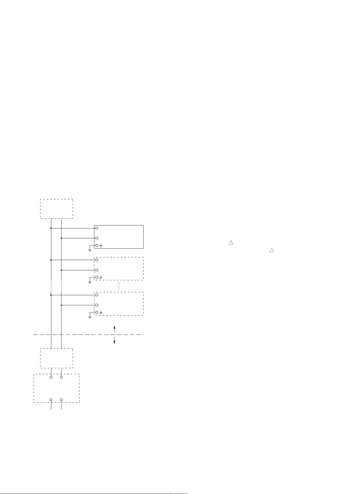
IFM026-A12
Installation Diagram for Nonincendive
(Division 2 Installation)
Terminator
Pressure
Transmitter
SUPPLY
Transmitter
Transmitter
Hazardous location
Non-Hazardous location
Terminator
General Purpose
Equipment
FM Approved
Associated Nonincendive Field
Wiring Apparatus
Vt or Voc
It or Isc
Ca
La
Note 1. Installation should be in accordance with the
National Electrical Code ® (ANSI/NFPA 70)
Article 500.
Note 2. The configuration of Associated Nonincendive
Field Wiring Apparatus must be FM
Approved.
Note 3. Approved under FNICO Concept.
Note 4. Dust-tight conduit seal must be used when
installed in Class II and Class III environ-
ments.
Note 5. Associated Apparatus manufacturer’s installa-
tion drawing must be followed when installing
this apparatus.
Note 6. No revision to drawing without prior FM
Approvals.
Note 7. Terminator must be FM Approved.
Note 8. The nonincendive field wiring circuit concept
allows interconection of nonincendive field
wiring apparatus with associated nonincendive
field wiring apparatus, using any of the wiring
methods permitted for unclassified locations.
Note 9. Installation requirements;
Vmax Voc or Vt
Imax = see note 10.
Ca Ci + Ccable
La Li + Lcable
Note 10. For this current controlled circuit, the param-
eter (Imax 3) is not required and need not be
aligned with parameter (Isc 3) of the barrier
or associated nonincendive field wiring
apparatus.
Note 11. If ordinary location wiring methods are used,
the transmitter shall be connected to FM
Approved associated non-incendive field
wiring apparatus.
Electrical data:
[Supply circuit]
Vmax: 32 V
Ci: 1.76 mF
Li: 0 mH
[Sensor circuit]
Vt: 6 V
It: 25 mA
Po: 0.15 W
Ca: 40 F
La: 40 mH
F0204.EPS
2-2
IM 01C25R03-01E

2. HANDLING CAUTIONS
FNICO Rules
The FNICO Concept allows the interconnection of
nonincendive field wiring apparatus to associated
nonincendive field wiring apparatus not specifically
examined in such combination. The criterion for such
interconnection is that the voltage (Vmax), the current
(Imax) and the power (Pmax) which nonincendive field
wiring apparatus can receive and remain nonincendive,
considering faults, must be equal or greater than the
voltage (Uo, Voc or Vt), the current (Io, Isc or It) and
the power (Po) which can be provided by the associated nonincendive field wiring apparatus (supply unit).
In addition the maximum unprotected residual capacitance (Ci) and inductance (Li) of each apparatus (other
than terminators) connected to the Fieldbus must be
less than or equal to 5nF and 10uH respectively.
In each N.I. Fieldbus segment only one active source,
normally the associated nonincendive field wiring
apparatus, is allowed to provide the necessary power
for the Fieldbus system. The allowed voltage (Uo, Voc
or Vt) of the associated nonincendive field wiring
apparatus used to supply the bus cable must be limited
to the range 14Vdc to 17.5Vdc. All other equipment
connected to the bus cable has to be passive, meaning
that the apparatus is not allowed to provide energy to
the system, except a leakage current of 50É A for each
connected device. Separately powered equipment needs
galvanic isolation to ensure the nonincendive field
wiring Fieldbus circuit remains passive.
Cable
The cable used to interconnect the devices needs to
comply with the following parameters:
Loop resistance R': 15...150 Ω/km
Inductance per unit length L': 0.4...1 mH/km
Capacitance per unit length C': 80....200 nF/km
C' =C' line/line+0.5 C' line/screen, if both lines are
floating or C' = C' line/line + C'line/screen, if
thescreen is connected to one line.
Length of spur cable: max. 30 m
Length of trunk cable: max. 1 km
Length of splice: max = 1 m
Terminators
At the end of each trunk cable an FM Approved line
terminator with the following parameters is suitable:
R= 90...100 Ω
C = 0 ....2.2 uF
2.1.2 CSA Certification
a. CSA Explosionproof Type
Caution for CSA explosionproof type.
Note 1. Model EJX910A Multivariable transmitter
with optional code /CF1 is applicable for
use in hazardous locations:
[For CSA C22.2]
• Explosion-proof for Class I, Groups B, C and D.
• Dustignition-proof for Class II/III, Groups E, F and
G.
• Enclosure: TYPE 4X
• Temperature Code: T6...T4
[For CSA E60079]
• Flameproof for Zone 1, Ex d IIC T6...T4
• Enclosure: IP66 and IP67
• Maximum Process Temperature: 120°C (T4),
100°C (T5), 85°C (T6)
• Ambient Temperature: –50 to 75°C (T4), –50 to
80°C (T5), –50 to 72 õ (T6)
• Supply Voltage: 32 V dc max.
• Output Signal: 15 mA dc
Note 2. Wiring
• All wiring shall comply with Canadian Electrical
Code Part I and Local Electrical Codes.
• In hazardous location, wiring shall be in conduit as
shown in the figure.
• WARNING:
A SEAL SHALL BE INSTALLED WITHIN 50cm
OF THE ENCLOSURE.
UN SCELLEMENT DOIT ÊTRE INSTALLÉ À
MOINS DE 50cm DU BOÎTIER.
• WARNING:
WHEN INSTALLED IN CL.I, DIV 2, SEAL NOT
REQUIRED.
UNE FOIS INSTALLÉ DANS CL I, DIV 2,
AUCUN JOINT N'EST REQUIS.
Note 3. Operation
• WARNING:
AFTER DE-ENERGIZING, DELAY 5 MINUTES
BEFORE OPENING.
APRÉS POWER-OFF, ATTENDRE 5 MINUTES
AVANT D'OUVRIR.
• WARNING:
WHEN AMBIENT TEMPERATURE ≥ 65°C,
USE THE HEAT-RESISTING CABLES ≥ 90°C.
QUAND LA TEMPÉRATURE AMBIANTE ≥
65°C, UTILISEZ DES CÂBLES RÉSISTANTES Á
LA CHALEUR ≥ 90°C.
• Take care not to generate mechanical sparking
when accessing to the instrument and peripheral
devices in a hazardous location.
2-3
IM 01C25R03-01E
2. HANDLING CAUTIONS
Note 4. Maintenance and Repair
• The instrument modification or parts replacement
by other than authorized representative of
Yokogawa Electric Corporation and Yokogawa
Corporation of America is prohibited and will void
Canadian Standards Explosionproof Certification.
Non-Hazardous
Locations
Non-hazardous
Location
Equipment
32 V DC Max.
15 mA DC
Signal
Non-Hazardous
Locations
Non-hazardous
Location
Equipment
32 V DC Max.
15 mA DC
Signal
Hazardous Locations Division 1
50 cm Max.
S
UP
P
Conduit
LY
Sealing Fitting
EJX 910A
Hazardous Locations Division 2
S
U
P
P
LY
Sealing Fitting
EJX 910A
E
S
UL
P
K
EC
H
C
M
AR
L
A
E
S
PUL
CK
E
H
C
RM
A
L
A
F0205E.EPS
2.1.3 CENELEC ATEX Certification
(1) Technical Data
a. CENELEC ATEX (KEMA) Flameproof Type
Caution for CENELEC ATEX (KEMA) flameproof
type
Note 3. Installation
• All wiring shall comply with local installation requirements.
•The cable entry devices shall be of a
certified flameproof type, suitable for the
conditions of use.
Note 4. Operation
• Keep the “WARNING” label attached to the
transmitter.
WARNING: AFTER DE-ENERGIZING,
DELAY 5 MINUTES BEFORE
OPENING. WHEN THE AMBIENT
TEMP.65°C, USE HEAT-RESISTING
CABLES90°C.
• Take care not to generate mechanical
sparking when accessing the instrument and
peripheral devices in hazardous location.
Note 5. Maintenance and Repair
• The instrument modification or part replacement by other than an authorized representative of Yokogawa Electric Corporation is
prohibited and will void KEMA Flameproof
Certification.
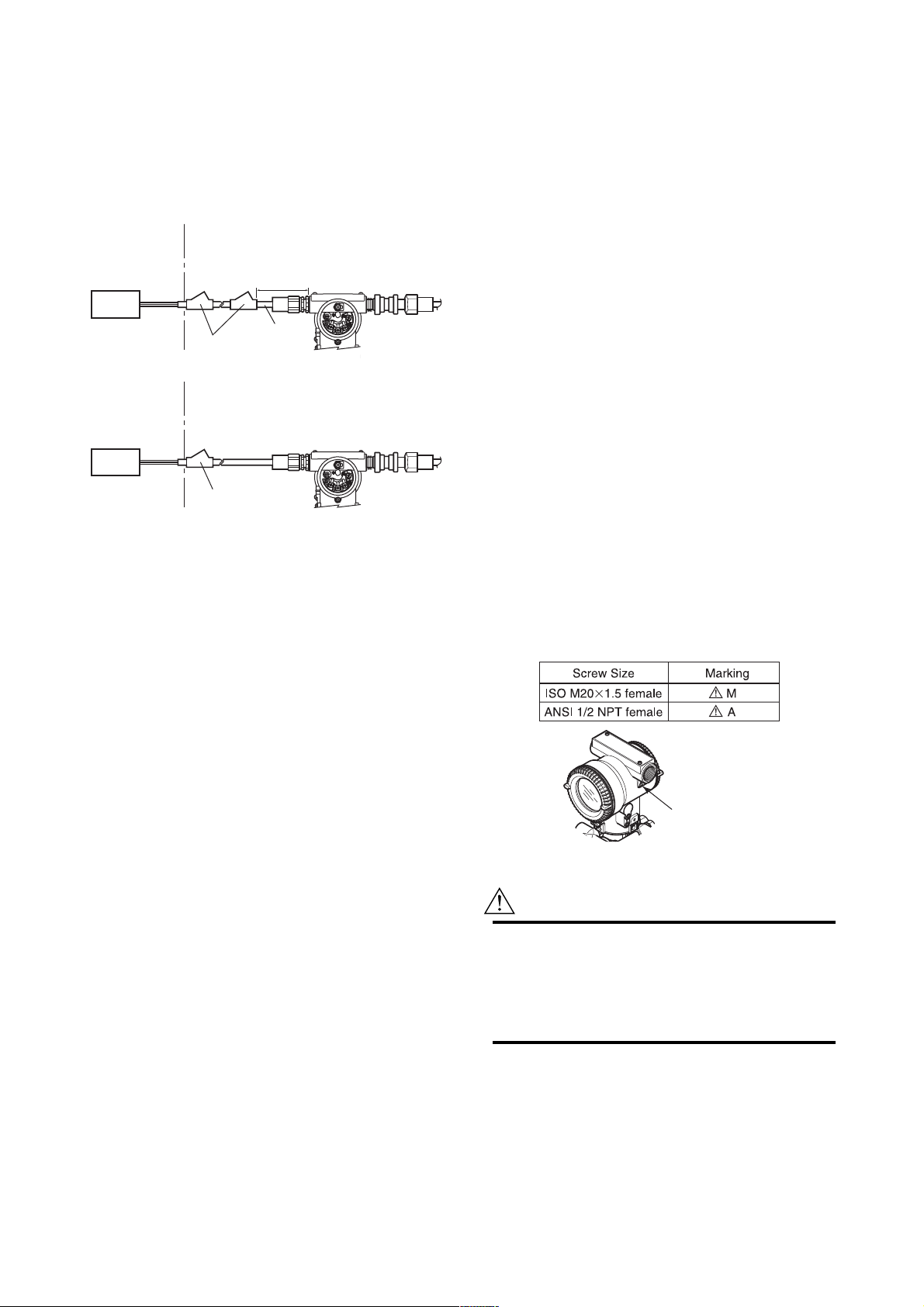
(2) Electrical Connection
A mark indicating the electrical connection type is
stamped near the electrical connection port. These
marks are as follows.
Note 1. EJX910A Multivariable transmitter with
optional code /KF2 for potentially explosive
atmospheres:
• No. KEMA 03ATEX2570
• Type of Protection and Marking Code: EEx
d IIC T6...T4
• Group: II
• Category: 2G, 1D
• Temperature Class: T6, T5, and T4
• Enclosure: IP66 and IP67
• Ambient Temperature for gas-proof:
–50 to 70°C (T6), –50 to 80°C (T5), and
–50 to 75°C (T4)
• Maximum Process Temperature (Tp.) for
gas-proof:
85°C (T6), 100°C (T5), and 120°C (T4)
• Maximum Surface Temperature for dust-proof:
T80°C (Tamb.: –40 to 40°C, Tp.: 80°C)
T100°C (Tamb.: –40 to 60°C, Tp.: 100°C)
T120°C (Tamb.: –40 to 80°C, Tp.: 120°C)
Note 2. Electrical Data
• Supply voltage: 32 V dc max.
Output current: 15 mA dc
T0201.EPS
Location of the mark
F0201.EPS
(3) Installation
WARNING
•All wiring shall comply with local installation
requirements and the local electrical code.
•There is no need for a conduit seal in Division
1 and Division 2 hazardous locations because
this product is sealed at the factory.
2-4
IM 01C25R03-01E
2. HANDLING CAUTIONS
(4) Operation
WARNING
• OPEN CIRCUIT BEFORE REMOVING
COVER. INSTALL IN ACCORDANCE WITH
THIS USER’S MANUAL
• Take care not to generate mechanical sparking
when accessing the instrument and peripheral
devices in a hazardous location.
(5) Maintenance and Repair
WARNING
The instrument modification or part replacement
by other than an authorized Representative of
Yokogawa Electric Corporation is prohibited and
will void the certification.
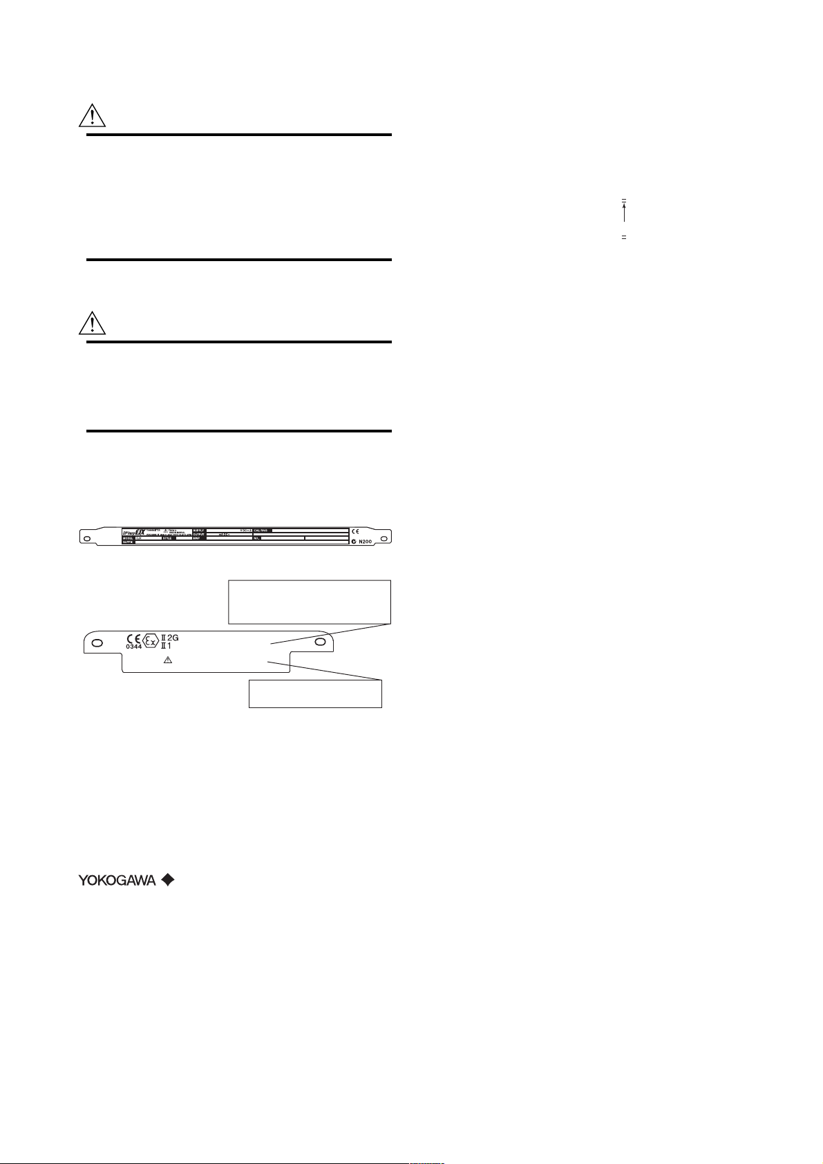
(6) Name Plate
*1: The first digit in the final three numbers of the
serial number appearing after “NO.” on the name
plate indicates the year of production. The following is an example of a serial number for a product
that was produced in 2004:
12A819857 432
The year 2004
*2: “180-8750” is the Zip code for the following
address.
2-9-32 Nakacho, Musashino-shi, Tokyo Japan
Name plate
Tag plate for flameproof type
No. KEMA 03ATEX2570
EEx d IIC T6...T4 IP66 andIP67
TEMP. CLASS T6 T5 T4
MAX PROCESS TEMP.(Tp.) 85 100 120 °C
Tamb. -50 to 70 80 75 °C
T80°C(Tamb.:40°C, Tp.:80°C),T100°C(Tamb.:60°C, Tp.:100°C),
T120°C(Tamb.:80°C, Tp.:120°C) Min.Tamb.:-40°C(for DUST)
D
WARNING
AFTER DE-ENERGIZING, DELAY 5 MINUTES
BEFORE OPENING.
WHEN THE AMBIENT TEMP. 65°C,
USE THE HEAT-RESISTING CABLES 90°C
MODEL: Specified model code.
STYLE: Style code.
SUFFIX: Specified suffix code.
SUPPLY: Supply voltage.
OUTPUT: Output signal.
MWP: Maximum working pressure.
CAL RNG: Specified calibration range.
NO.: Serial number and year of production*1.
TOKYO 180-8750 JAPAN:
The manufacturer name and the address*2.
F0202.EPS
2-5
IM 01C25R03-01E

3. ABOUT FIELDBUS
3. ABOUT FIELDBUS
3.1 Outline
Fieldbus is a widely used bi-directional digital communication protocol for field devices that enable the
simultaneous output to many types of data to the
process control system.
The EJX910A Fieldbus communication type employs
the specification standardized by The Fieldbus Foundation, and provides interoperability between Yokogawa
devices and those produced by other manufacturers.
Fieldbus comes with software consisting of five AI
function blocks that enable the flexible implementation
of systems.
For information on other features, engineering, design,
construction work, startup and maintenance of
Fieldbus, refer to “Fieldbus Technical Information” (TI
38K03A01-01E).
3.2 Internal Structure of EJX910A
The EJX910A contains two virtual field devices (VFD)
that share the following functions.
3.2.1 System/network Management VFD
• Sets node addresses and Physical Device tags (PD
Tag) necessary for communication.
• Controls the execution of function blocks.
•Manages operation parameters and communication
resources (Virtual Communication Relationship:
VCR).
(4)LCD Transducer block
• Controls the display of the integral indicator.
(5)AI function block
• Condition raw data from the Transducer block.
• Output differential pressure, static pressure and
capsule temperature signals.
• Carry out scaling, damping and square root extraction.
(6)SC function block
• Converts the input signal value based on the
segment table function.
(7)IT function block
• Integrates one or two input signals and outputs the
result.
(8)IS function block
• Selects one of multiple input signals according to
the specified selection method and outputs the
signal.
(9)AR function block
• Performs ten types of calculations on a combination
of two main input signals and three auxiliary input
signals.
(10)PID function block
• Performs the PID control computation based on the
deviation of the measured value from the setpoint.
3.2.2 Function Block VFD
(1)Resource block
• Manages the status of EJX910A hardware.
•Automatically informs the host of any detected
faults or other problems.
(2)SENSOR Transducer block
• Converts sensor output to pressure, static pressure,
and capsule temperature signals, and transfers to the
AI function blocks and flow transducer blok.
(3)FLOW Transducer block
• Accepts differential pressure, static pressure and
external temperature data from the transducer block,
calculates flow, and transfer to the AI function
block.
3-1
IM 01C25R03-01E
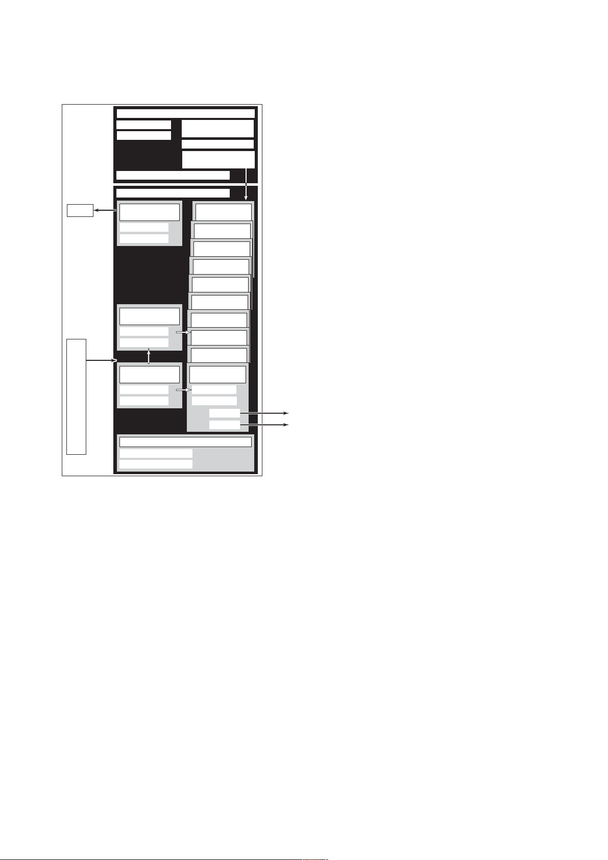
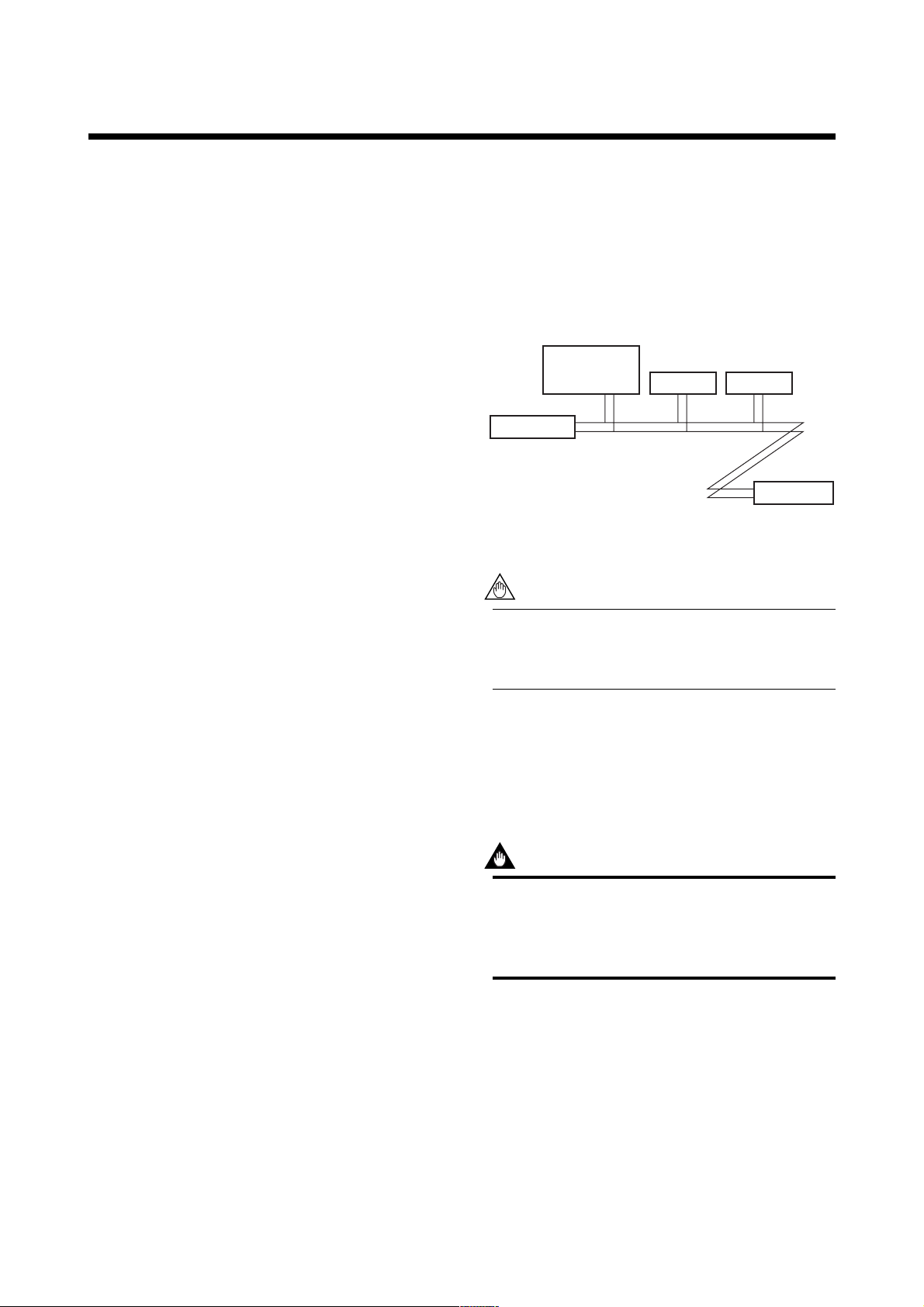
3.3 Logical Structure of Each
Block
3. ABOUT FIELDBUS
EJX910A
Fieldbus
LCD
Sensor
input
Sensor
System/network management VFD
PD Tag
Node address
Link Master
Function block VFD
LCD
Transducer block
Block tag
Parameters
Flow
Transducer block
Block tag
Parameters
SENSOR
Transducer block
Block tag
Parameters
Communication
parameters
VCR
Function block
execution schedule
PID function
block (option)
AR function
block
IS function
block
IT function
block
SC function
block
AI function
block
AI function
block
AI function
block
AI function
block
AI function
block
Block tag
Parameters
OUT_D
Output
OUT
Resource block
Block tag
Parameters
F0301.EPS
Figure 3.1 Logical Structure of Each Block
Setting of various parameters, node addresses, and PD
Tags shown in Figure 3.1 is required before starting
operation.
3.4 Wiring System Configuration
The number of devices that can be connected to a
single bus and the cable length vary depending on
system design. When constructing systems, both the
basic and overall design must be carefully considered
to achieve optimal performance.
3-2
IM 01C25R03-01E
4. GETTING STARTED
4. GETTING STARTED
Fieldbus is fully dependent upon digital communication protocol and differs in operation from conventional 4 to 20 mA transmission and the HART communication protocol. It is recommended that novice users
use field devices in accordance with the procedures
described in this section. The procedures assume that
field devices will be set up on a bench or in an
instrument shop.
4.1 Connection of Devices
The following are required for use with Fieldbus
devices:
• Power supply:
Fieldbus requires a dedicated power supply. It is
recommended that current capacity be well over the
total value of the maximum current consumed by all
devices (including the host). Conventional DC
current cannot be used as is.
• Terminator:
Fieldbus requires two terminators. Refer to the
supplier for details of terminators that are attached
to the host.
•Field devices:
Connect Fieldbus communication type EJX910A.
Two or more EJX devices or other devices can be
connected.
• Host:
Used for accessing field devices. A dedicated host
(such as DCS) is used for an instrumentation line
while dedicated communication tools are used for
experimental purposes. For operation of the host,
refer to the instruction manual for each host. No
other details on the host are given in this manual.
•Cable:
Used for connecting devices. Refer to “Fieldbus
Technical Information” (TI 38K03A01-01E) for
details of instrumentation cabling. For laboratory or
other experimental use, a twisted pair cable two to
three meters in length with a cross section of
0.9 mm2 or more and a cycle period of within 5 cm
(2 inches) may be used. Termination processing
depends on the type of device being deployed. For
EJX910A, use an M4 screw terminal claw. Some
hosts require a connector.
Refer to Yokogawa when making arrangements to
purchase the recommended equipment.
Connect the devices as shown in Figure 4.1. Connect
the terminators at both ends of the trunk, with a
minimum length of the spur laid for connection.
The polarity of signal and power must be maintained.
Fieldbus power
supply
Terminator
Figure 4.1 Cabling
EJX910A
HOST
Terminator
F0401.EPS
NOTE
No CHECK terminal is used for Fieldbus
EJX910A. Do not connect the field indicator and
check meter.
Before using a Fieldbus configuration tool other than
the existing host, confirm it does not affect the loop
functionality in which all devices are already installed
in operation. Disconnect the relevant control loop from
the bus if necessary.
IMPORTANT
Connecting a Fieldbus configuration tool to a
loop with its existing host may cause communication data scrambling resulting in a functional
disorder or a system failure.
4-1
IM 01C25R03-01E

4. GETTING STARTED
4.2 Host Setting
To activate Fieldbus, the following settings are
required for the host. Set the available address range to
cover the address set for EJX910A’s.
IMPORTANT
Do not turn off the power immediately after
setting. When the parameters are saved to the
EEPROM, the redundant processing is executed
for an improvement of reliability. If the power is
turned off within 60 seconds after setting is
made, the modified parameters are not saved
and the settings may return to the original
values.
Table 4.1 Operation Parameters
Symbol Parameter Description and Settings
V (ST)
V (MID)
V (MRD)
V (FUN)
V (NUN)
Slot-Time
Minimum-Inter-PDUDelay
Maximum-ReplyDelay
First-Unpolled-Node
Number-ofconsecutiveUnpolled-Node
Indicates the time necessary
for immediate reply of the
device. Unit of time is in
octets (256 µs). Set
maximum specification for
all devices. For EJX910A,
set a value of 4 or greater.
Minimum value of
communication data
intervals. Unit of time is in
octets (256 µs). Set the
maximum specification for
all devices. For EJX910A,
set a value of 4 or greater.
The worst case time
elapsed until a reply is
recorded. The unit is Slottime; set the value so that
V (MRD) V (ST) is the
maximum value of the
specification for all
devices. For EJX910A, the
setting must be a value of
12 or greater.
Indicate the address next
to the address range used
by the host. Set 015 or
greater.
Unused address range.
T0401.EPS
0x00
Not used
0x0F
0x10
0x13
0x14
V(FUN)
V(FUN)V(NUN)
0xF7
0xF8
0xFB
0xFC
0xFF
Note 1: Bridge device: A linking device which brings data from one
or more H1 networks.
Note 2: LM device: with bus control function (Link Master function)
Note 3: BASIC device: without bus control function
Figure 4.2 Available Address Range
Bridge device
LM device
Unused V(NUN)
BASIC device
Default address
Portable device address
F0402.EPS
4-2
IM 01C25R03-01E

4. GETTING STARTED
4.3 Bus Power ON
Turn on the power of the host and the bus. Where the
EJX910A is equipped with an LCD indicator, first all
segments are lit, then the display begins to operate. If
the indicator is not lit, check the polarity of the power
supply.
Using the host device display function, check that the
EJX910A is in operation on the bus.
The device information, including PD tag, Node
address, and Device ID, is described on the sheet
attached to the EJX910A. The device information is
given in duplicate on this sheet.
Device ID : 594543000EXXXXXXXX
PD Tag : FT1001
Device Revision : 1
Node Address : 0xf5
Serial No. : XXXXXXXXXXXXXXXXX
Physical Location :
Note:
Our Device Description Files and Capabilities Files available at
http://www.yokogawa.com/fld (English) or
http://www.yokogawa.co.jp/Sensor/fieldbus/fieldbus.htm (Japanese)
DEVICE INFORMATION
4.4 Integration of DD
If the host supports DD (Device Description), the DD
of the EJX910A needs to be installed. Check if host
has the following directory under its default DD
directory.
594543\000E
(594543 is the manufacturer number of Yokogawa
Electric Corporation, and 000E is the EJX910A
device number, respectively.)
If this directory is not found, the DD of the EJX910A
has not been included. Create the above directory and
copy the DD file (0m0n.ffo, 0m0n.sym) (m, n is a
numeral) into the directory. ‘0m’ in the file name
shows the device revision, and ‘0n’ shows the DD
revision. If you do not have the DD or capabilities
files, you can download them from our web site:
http://www.yokogawa.com/fld
Once the DD is installed in the directory, the name and
attribute of all parameters of the EJX910A are displayed.
Off-line configuration is possible by using capabilities
files.
Device ID : 594543000EXXXXXXXX
PD Tag : FT1001
Device Revision : 1
Node Address : 0xf5
Serial No. : XXXXXXXXXXXXXXXXX
Physical Location :
Note:
Our Device Description Files and Capabilities Files available at
http://www.yokogawa.com/fld (English) or
http://www.yokogawa.co.jp/Sensor/fieldbus/fieldbus.htm (Japanese)
Figure 4.3 Device Information Sheet Attached to EJX
DEVICE INFORMATION
F0403.EPS
If no EJX910A is detected, check the available address
range and the polarity of the power supply. If the node
address and PD tag are not specified when ordering,
default value is factory set. If two or more EJX910As
are connected at a time with default value, only one
EJX910A will be detected from the host as EJX910As
have the same initial address. Separately connect each
EJX910A and set a different address for each.
EJX has two capabilities levels, “1” and “2”.
Select “Capabilities level = 1” when the EJX910A
don’t have LC1(PID function) option.
Select “Capabilities level = 2” when the EJX910A has
LC1(PID function) option.
The capabilities level defines the kind and the number
of function blocks that can be used.
The table below shows the relation.
The relation between and function blocks that can be used
Capabilities
Level
1
2
AI SC IT IS AR PID
5
11110
511111
T0402.EPS
4.5 Reading the Parameters
To read EJX910A parameters, select the AI1 block of
the EJX910A from the host screen and read the OUT
parameter. The current selected signal is displayed.
Check that MODE_BLOCK of the function block and
resource block is set to AUTO, and change the signal
input and read the parameter again. A new designated
value should be displayed.
4-3
IM 01C25R03-01E

4.6 Continuous Record of Values
If the host has a function that continuously records the
indications, use this function to list the indications
(values). Depending on the host being used, it may be
necessary to set the schedule of Publish (the function
that transmits the indication on a periodic basis).
4.7 Generation of Alarm
Generation of an alarm can be attempted from
EJX910A. Block alarm, Output limit alarm, and
Update alarm are informed to the host. When generating alarm, a Link Object and a VCR Static Entry need
to be set. For details of Link Object and VCR Static
Entry, refer to section 5.6.1 Link object and section
5.5.1 VCR Setting.
4. GETTING STARTED
4-4
IM 01C25R03-01E

5. CONFIGURATION
5. CONFIGURATION
This chapter describes how to adapt the function and
performance of the EJX910A to suit specific applications. Because multiple devices are connected to
Fieldbus, it is important to carefully consider the
device requirements and settings when configuring the
system. The following steps must be taken.
(1)Network design
Determines the devices to be connected to Fieldbus
and checks the capacity of the power supply.
(2)Network definition
Determines the tag and node addresses for all
devices.
(3)Definition of combining function blocks
Determines how function blocks are combined.
(4)Setting tags and addresses
Sets the PD Tag and node addresses for each device.
(5)Communication setting
Sets the link between communication parameters
and function blocks.
(6)Block setting
Sets the parameters for function blocks.
The following section describes in sequence each step
of this procedure. The use of a dedicated configuration
tool significantly simplifies this procedure. Refer to
Appendix 6 when the EJX910A is used as Link
Master.
• Terminator
Fieldbus requires two terminators. Refer to the
supplier for details of terminators that are attached
to the host.
•Field devices
Connect the field devices necessary for instrumenta-
tion. The EJX910A has passed the interoperability
test conducted by The Fieldbus Foundation. In order
to properly start Fieldbus, it is recommended that
the devices used satisfy the requirements of the
above test.
• Host
Used for accessing field devices. A minimum of one
device with the bus control function is needed.
• Cable
Used for connecting devices. Refer to “Fieldbus
Technical Information” for details of instrumentation
cabling. Provide a cable sufficiently long to connect
all devices. For field branch cabling, use terminal
boards or a connection box as required.
First, check the capacity of the power supply. The
power supply capacity must be greater than the sum of
the maximum current consumed by all devices to be
connected to Fieldbus. The maximum current consumed (power supply voltage 9 V to 32 V) for the
EJX910A is 15 mA (24 mA in Software download
operation). The cable used for the spur must be of the
minimum possible length.
5.1 Network Design
Select the devices to be connected to the Fieldbus
network. The following are essential for the operation
of Fieldbus.
• Power supply
Fieldbus requires a dedicated power supply. It is
recommended that current capacity be well over the
total value of the maximum current consumed by all
devices (including the host). Conventional DC
current cannot be used as is.
5.2 Network Definition
Before connection of devices with Fieldbus, define the
Fieldbus network. Allocate PD Tag and node addresses
to all devices (excluding such passive devices as
terminators).
The PD Tag is the same as the conventional one used
for the device. Up to 32 alphanumeric characters may
be used for definition. Use a hyphen as a delimiter as
required.
The node address is used to specify devices for
communication purposes. Because this data is too long
for a PD Tag, the host uses the node address in place
of the PD Tag for communication. A range of 20 to
247 (or hexadecimal 14 to F7) can be set. The device
5-1
IM 01C25R03-01E

5. CONFIGURATION
(LM device) with bus control function (Link Master
function) is allocated from a smaller address number
(20) side, and other devices (BASIC device) without
bus control function allocated from a larger address
number (247) side respectively. Place the EJX910A in
the range of the BASIC device. When the EJX910A is
used as Link Master, place the EJX910A in the range
of the LM device. Set the range of addresses to be used
to the LM device. Set the following parameters.
Table 5.1 Parameters for Setting Address Range
Symbol
V (FUN) First-Unpolled-Node
V (NUN) Number-of-
Parameters Description
Indicates the address next
to the address range used
for the host or other LM
device.
Unused address range
consecutiveUnpolled-Node
T0501.EPS
The devices within the address range written as
“Unused” in Figure 5.1 cannot be used on a Fieldbus.
For other address ranges, the range is periodically
checked to identify when a new device is mounted.
Care must be taken to keep the unused device range as
narrow as possible so as to lessen the load on the
Fieldbus.
0x00
0x0F
0x10
0x13
0x14
V(FUN)
V(FUN)V(NUN)
0xF7
0xF8
0xFB
0xFC
0xFF
Figure 5.1 Available Range of Node Addresses
Not used
Bridge device
LM device
Unused V(NUN)
BASIC device
Default address
Portable device address
F0501.EPS
To ensure stable operation of Fieldbus, determine the
operation parameters and set them to the LM devices.
While the parameters in Table 5.2 are to be set, the
worst-case value of all the devices to be connected to
the same Fieldbus must be used. Refer to the specification of each device for details. Table 5.2 lists EJX910A
specification values.
Table 5.2 Operation Parameter Values of the EJX910A to
be Set to LM Devices
Symbol Parameters Description and Settings
V (ST) Slot-Time
V (MID) Minimum-Inter-PDU-
Delay
V (MRD) Maximum-Reply-Delay
Indicates the time necessary
for immediate reply of the
device. Unit of time is in
octets (256 µs). Set
maximum specification for
all devices. For EJX910A,
set a value of 5 or greater.
Minimum value of
communication data
intervals. Unit of time is in
octets (256 µs). Set the
maximum specification for
all devices. For EJX910A,
set a value of 4 or greater.
The worst case time
elapsed until a reply is
recorded. The unit is Slottime; set the value so that
V (MRD) V (ST) is the
maximum value of the
specification for all
devices. For EJX910A, the
setting must be a value of
12 or greater.
T0502.EPS
5.3 Definition of Combining Function Blocks
The input/output parameters for function blocks are
combined. As required, they can be combined with the
input of the control block. The setting is written to the
EJX910A link object. See “Block setting” in Section
5.6 for the details. It is also possible to read values
from the host at proper intervals instead of connecting
the EJX910A block output to other blocks.
The combined blocks need to be executed synchronously with other blocks on the communications
schedule. In this case, change the EJX910A schedule
according to the following table. The values in the
table are factory-settings.
Table 5.3 Execution Schedule of the EJX Function Blocks
Index Parameters
269
MACROCYCLE_
(SM)
DURATION
276
FB_START_ENTRY.1
(SM)
277
FB_START_ENTRY.2
(SM)
278
FB_START_ENTRY.3
(SM)
279
FB_START_ENTRY.4
(SM)
280 to
FB_START_ENTRY.5
289
(SM)
FB_START_ENTRY.14
to
Setting (Enclosed is
factory-setting)
Cycle (MACROCYCLE)
period of control or
measurement. Unit is 1/32
ms. (16000 = 0.5 s)
AI1 block startup time.
Elapsed time from the start
of MACROCYCLE specified
in 1/32 ms. (0 = 0 s)
AI2 block startup time.
Elapsed time from the start
of MACROCYCLE specified
in 1/32ms.(8000=250ms)
AI3 block startup time.
Elapsed time from the start
of MACROCYCLE specified
in 1/32ms.(16000=500ms)
AI4 block startup time.
Elapsed time from the start
of MACROCYCLE specified
in 1/32ms. (24000=750ms)
Not used.
T0503.EPS
5-2
IM 01C25R03-01E
5. CONFIGURATION
A maximum of 30 ms is taken for execution of AI
block. For scheduling of communications for combination with the next function block, the execution is so
arranged as to start after a lapse of longer than 30 ms.
In no case should function blocks of the EJX910A be
executed at the same time (execution time is overlapped).
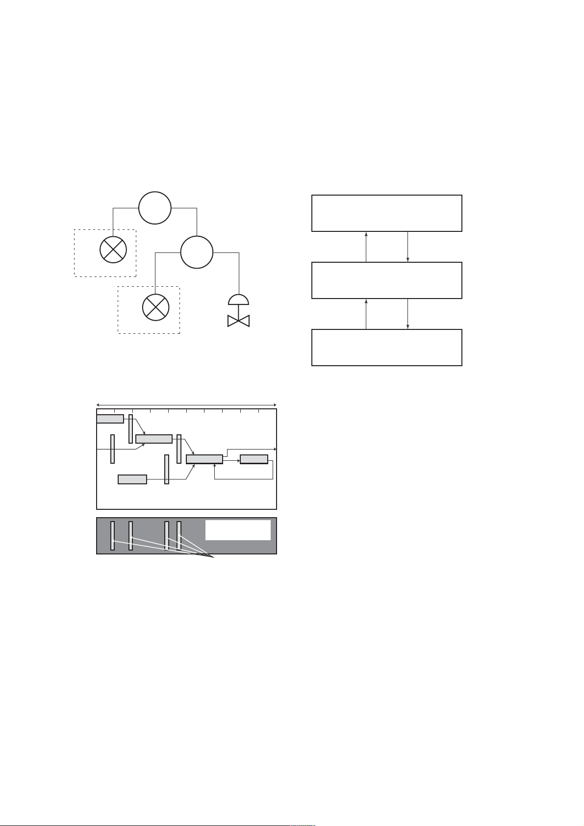
Figure 5.3 shows an example of schedule based on the
loop shown in Figure 5.2.
LIC100
EJX
910A
#1
LI100
EJX
910A
#2
FI100
Figure 5.2 Example of Loop Connecting Function Block of
Two EJX with Other Instruments
Macrocycle (Control Period)
FIC100
FC100
F0502.EPS
5.4 Setting of Tags and Addresses
This section describes the steps in the procedure to set
PD Tags and node addresses in the EJX910A. There
are three states of Fieldbus devices as shown in Figure
5.4, and if the state is other than the lowest
SM_OPERATIONAL state, no function block is
executed. EJX910A must be transferred to this state
when an EJX910A tag or address is changed.
UNINITIALIZED
(No tag nor address is set)
Tag clear Tag setting
INITIALIZED
(Only tag is set)
Address clear
SM_OPERATIONAL
(Tag and address are retained, and
the function block can be executed.)
Figure 5.4 Status Transition by Setting PD Tag and Node
Address
Address setting
F0504.EPS
LI100
OUT
Commu-
nication
Schedule
Figure 5.3 Function Block Schedule and Communication
Schedule
IN
LIC100
BKCAL_IN
FI100
OUT
CAS_IN
FIC100
IN
BKCAL_IN
Unscheduled
Communication
BKCAL_OUT
FC100
BKCAL_OUT
Scheduled
Communication
F0503.EPS
When the control period (macrocycle) is set to more
than 4 seconds, set the following intervals to be more
than 1% of the control period.
- Interval between “end of block execution” and “start
of sending CD from LAS”
- Interval between “end of block execution” and “start
of the next block execution”
EJX910A has a PD Tag (FT2001) and node address
(245, or hexadecimal F5) that are set upon shipment
from the factory unless otherwise specified. To change
only the node address, clear the address once and then
set a new node address. To set the PD Tag, first clear
the node address and clear the PD Tag, then set the PD
Tag and node address again.
Devices whose node addresses have been cleared will
have the default address (randomly chosen from a
range of 248 to 251, or from hexadecimal F8 to FB).
At the same time, it is necessary to specify the device
ID in order to correctly specify the device. The device
ID of the EJX910A is 594543000Exxxxxxxx. (The
xxxxxxxx at the end of the above device ID is a total
of 8 alphanumeric characters.)
5-3
IM 01C25R03-01E

5. CONFIGURATION
5.5 Communication Setting
To set the communication function, it is necessary to
change the database residing in SM-VFD.
5.5.1 VCR Setting
Set VCR (Virtual Communication Relationship), which
specifies the called party for communication and
resources. EJX910A has 33 VCRs whose application
can be changed, except for the first VCR, which is
used for management.
EJX910A has VCRs of four types:
Server(QUB) VCR
A Server responds to requests from a host. This
communication needs data exchange. This type of
communication is called QUB (Queued Usertriggered Bidirectional) VCR.
Source (QUU) VCR
A Source multicasts alarms or trends to other
devices. This type of communication is called QUU
(Queued User-triggered Unidirectional) VCR.
Publisher (BNU) VCR
A Publisher multicasts block output to another
function block(s). This type of communication is
called BNU (Buffered Network-triggered Unidirectional) VCR.
Subscriber (BNU) VCR
A Subscriber receives output of another function
block(s).
A Server VCR is capable to responding to requests
from a Client (QUB) VCR after the Client successfully
initiates connection to the Server. A Source VCR
transmits data without established connection. A Sink
(QUU) VCR on another device can receive it if the
Sink is configured so. A Publisher VCR transmits data
when LAS requests so. An explicit connection is
established from Subscriber (BNU) VCR(s) so that a
Subscriber knows the format of published data.
Each VCR has the parameters listed in Table 5.4.
Parameters must be changed together for each VCR
because modification of individual parameters may
cause inconsistent operation.
Table 5.4 VCR Static Entry
Sub-
index
1 FasArTypeAndRole
2 FasDllLocalAddr
3 FasDllConfigured
4 FasDllSDAP
5 FasDllMaxConfirm
6 FasDllMaxConfirm
7 FasDllMaxDlsduSize
8 FasDllResidual
9 FasDllTimelinessClass
10 FasDllPublisherTime
11 FasDllPublisher
Parameter Description
RemoteAddr
DelayOnConnect
DelayOnData
ActivitySupported
WindowSize
SynchronizaingDlcep
Indicates the type and role of
communication (VCR). The
following 4 types are used
for EJX.
0x32: Server (Responds to
requests from host.)
0x44: Source (Transmits
alarm or trend.)
0x66: Publisher (Sends
block output to other
blocks.)
0x76: Subscriber (Receives
output of other blocks.)
Sets the local address to
specify VCR in EJX. A range
of 20 to F7 in hexadecimal.
Sets the node address of the
called party for
communication and the
address (DLSAP or DLCEP)
used to specify VCR in that
address. For DLSAP or
DLCEP, a range of 20 to F7
in hexadecimal is used.
Addresses in Subindex 2
and 3 need to be set to the
same contents of the VCR
as the called party (local and
remote are reversed).
Specifies the quality of
communication. Usually, one
of the following types is set.
0x2B: Server
0x01: Source (Alert)
0x03: Source (Trend)
0x91: Publisher/Subscriber
To establish connection for
communication, a maximum
wait time for the called
party's response is set in
ms. Typical value is 60
secounds (60000).
For request of data, a
maximum wait time for the
called party's response is
set in ms. Typical value is
60 secounds (60000).
Specifies maximum DL
Service Data unit Size
(DLSDU). Set 256 for Server
and Trend VCR, and 64 for
other VCRs.
Specifies whether
connection is monitored. Set
TRUE (0xff) for Server. This
parameter is not used for
other communication.
Not used for EJX.
Not used for EJX.
Not used for EJX.
T0504-1.EPS
5-4
IM 01C25R03-01E

5. CONFIGURATION
Sub-
index
12 FasDllSubsriberTime
13 FasDllSubscriber
14 FmsVfdId
15 FmsMaxOutstanding
16 FmsMaxOutstanding
17 FmsFeatures
Parameter
WindowSize
SynchronizationDlcep
ServiceCalling
ServiceCalled
Supported
Description
Not used for EJX.
Not used for EJX.
Sets VFD for EJX to be
used.
0x1: System/network
management VFD
0x1234: Function block
VFD
Set 0 to Server. It is not
used for other applications.
Set 1 to Server. It is not
used for other applications.
Indicates the type of
services in the application
layer. In the EJX, it is
automatically set according
to specific applications.
T0504-2.EPS
33 VCRs are factory-set as shown in the table below.
Table 5.5 VCR List
Index
(SM)
293 For system management (Fixed)1
294 Server (LocalAddr = 0xF3)2
295 Server (LocalAddr = 0xF4)3
296 Server (LocalAddr = 0xF7)4
297 Trend Source (LocalAddr = 0x07,
298 Publisher for AI1 (LocalAddr = 0x20)6
299
300 Server (LocalAddr = 0xF9)8
301 Publisher for AI2 (LocalAddr = 0x21)9
302 to 315
VCR
Number
5
7
Factory Setting
Remote Address=0x111)
Alert Source (LocalAddr = 0x07,
Remote Address=0x110)
Not used.10 to 33
T0505.EPS
5.5.2 Function Block Execution Control
According to the instructions given in Section 5.3, set
the execution cycle of the function blocks and schedule
of execution.
5.6 Block Setting
Set the parameter for function block VFD.
5.6.1 Link Object
A link object combines the data voluntarily sent by the
function block with the VCR. The EJX910A has 40
link objects. A single link object specifies one combination. Each link object has the parameters listed in
Table 5.6. Parameters must be changed together for
each VCR because the modifications made to each
parameter may cause inconsistent operation.
Table 5.6 Link Object Parameters
Sub-
index
1 LocalIndex
2 VcrNumber
3RemoteIndex
4 ServiceOperation
5 StaleCountLimit
Set link objects as shown in Table 5.7.
Table 5.7 Factory-Settings of Link Objects (example)
Index Link Object # Factory Settings
30000 AI1.OUT → VCR#61
30001 Trend → VCR#52
30002 Alert → VCR#73
30003 AI2.OUT → VCR#94
30004 to
30039
Parameters Description
Sets the index of function
block parameters to be
combined; set “0” for Trend
and Alert.
Sets the index of VCR to
be combined. If set to “0”,
this link object is not used.
Not used in EJX. Set to “0”.
Set one of the following.
Set only one each for link
object for Alert or Trend.
0: Undefined
2: Publisher
3: Subscriber
6: Alert
7: Trend
Set the maximum number
of consecutive stale input
values which may be
received before the input
status is set to BAD. To
avoid the unnecessary
mode transition caused
when the data is not
correctly received by
subscriber, set this
parameter to “2” or more.
T0506.EPS
Not used5 to 40
T0507.EPS
5-5
IM 01C25R03-01E

5. CONFIGURATION
5.6.2 Trend Object
It is possible to set the parameter so that the function
block automatically transmits Trend. EJX910A has
seven Trend objects, six of which are used for Trend in
analog mode parameters and one is used for Trend in
discrete mode parameter. A single Trend object
specifies the trend of one parameter.
Each Trend object has the parameters listed in Table
5.8. The first four parameters are the items to be set.
Before writing to a Trend object, it is necessary to
release the WRITE_LOCK parameter.
Table 5.8 Parameters for Trend Objects
Sub-
index
1 Block Index
2 Parameter Relative
3 Sample Type
4 Sample Interval
5 Last Update
6 to 21 List of Status
21 to 37 List of Samples
Parameters
Index
Seven trend objects are factory-set as shown Table 5.9.
Description
Sets the leading index of
the function block that
takes a trend.
Sets the index of
parameters taking a trend
by a value relative to the
beginning of the function
block. In the EJX AI block,
the following three types of
trends are possible.
7: PV
8: OUT
19: FIELD_VAL
Specifies how trends are
taken. Choose one of the
following 2 types:
1: Sampled upon
execution of a function
block.
2: The average value is
sampled.
Specifies sampling
intervals in units of 1/32
ms. Set the integer
multiple of the function
block execution cycle.
The last sampling time.
Status part of a sampled
parameter.
Data part of a sampled
parameter.
T0508.EPS
SMIB
(System
Management
Information
Base)
NMIB
(Network
Management
Information
Base)
Link
object
VCR
Resource
block
#1
#2
FBOD
#3 #4
Transducer
block
#1 #2
#8
AI1 OUT
#4
#9
#6
AI2 OUT
Alert
#3
#7
Trend
#5
EJX
DLSAP
DLCEP
Fieldbus Cable
Figure 5.5 Example of Default Configuration
0xF8 0xF3 0xF4 0xF7
Host 1
Host 2
0xF9
Device 1
0x20 0x21
Device 2
0x07
F0505.EPS
5.6.3 View Object
This object forms a group of parameters in a block.
One advantage brought by forming groups of parameters is the reduction of load for data transactions.
View Object has the parameters listed in Table 5.11 to
5.15. Purpose of View Objects is shown in Table 5.10.
Table 5.10 Purpose of Each View Object
Description
VIEW_1
VIEW_2
VIEW_3
VIEW_4
Set of dynamic parameters required by operator
for plant operation. (PV, SV, OUT, Mode etc.)
Set of static parameters which need to be
shown to plant operator at once. (Range etc.)
Set of all the dynamic parameters.
Set of static parameters for configuration or
maintenance.
T0510.EPS
Table 5.9 Trend Object are Factory-Set
Index Parameters Factory Settings
32000 to
32005
32006 Not used.TREND_DIS.1
TREND_FLT.5
Not used.TREND_FLT.1 to
T0509.EPS
5-6
IM 01C25R03-01E

Table 5.11 View Object for Resource Block
Relative
Index
Parameter Mnemonic
1ST_REV 2
VIEW1VIEW2VIEW
22
2TAG_DESC
3STRATEGY
4 ALERT_KEY
5MODE_BLK 4
6 BLOCK_ERR 2
7 RS_STATE
11
8 TEST_RW
9DD_RESOURCE
10 MANUFAC_ID
11 DEV_TYPE
12 DEV_REV
13 DD_REV
14 GRANT_DENY
2
15 HARD_TYPES
16 RESTART
17 FEATURES
18 FEATURE_SEL
2
19 CYCLE_TYPE
20 CYCLE_SEL
2
21 MIN_CYCLE_T
22 MEMORY_SIZE
23 NV_CYCLE_T
24 FREE_SPACE
4
4
425 FREE_TIME
26 SHED_RCAS
27 SHED_ROUT
4
4
128 FAULT_STATE
29 SET_FSTATE
30 CLR_FSTATE
31 MAX_NOTIFY
32 LIM_NOTIFY
33 CONFIRM_TIME
34 WRITE_LOCK
1
4
1
35 UPDATE_EVT
36 BLOCK_ALM
37 ALARM_SUM
8
38 ACK_OPTION
39 WRITE_PRI 1
40 WRITE_ALM
41
ITK_VER
SOFT_REV
42
SOFT_DESC
43
44
SIM_ENABLE_MSG
45 DEVICE_STATUS_1
3
4
2
4
1
8
4
VIEW
4
2
2
1
4
2
1
1
2
2
2
4
2
1
2
2
T0511-1.EPS
Relative
Index
Parameter Mnemonic
46 DEVICE_STATUS_2
47 DEVICE_STATUS_3
48 DEVICE_STATUS_4
49 DEVICE_STATUS_5
50 DEVICE_STATUS_6
51 DEVICE_STATUS_7
52
DEVICE_STATUS_8
SOFTDWN_PROTECT
53
54
SOFTDWN_FORMAT
55
SOFTDWN_COUNT
SOFTDWN_ACT_AREA
56
SOFTDWN_MOD_REV
57
SOFTDWN_ERROR
58
Totals (# bytes)
5. CONFIGURATION
VIEW1VIEW2VIEW
3
4
4
4
4
4
4
4
1
16
2
22 30 73 35
VIEW
4
1
1
2
T0511-2.EPS
5-7
IM 01C25R03-01E

Table 5.12 View Object for SENSOR Transducer Block
Relative
Index
10
11
12
13
14
15
16
17
18
19
20
21
22
23
24
25
26
27
28
29
30
31
32
33
34
35
36
37
38
39
40
41
42
43
44
45
46
47
48
49
50
51
52
53
54
55
56
57
58
Parameter Mnemonic
ST_REV
1
TAG_DESC
2
STRATEGY
3
ALERT_KEY
4
MODE_BLK
5
BLOCK_ERR
6
UPDATE_EVT
7
BLOCK_ALM
8
TRANSDUCER_DIRECTORY
9
TRANSDUCER_TYPE
XD_ERROR
COLLECTION_DIRECTORY
PRIMARY_VALUE_TYPE
PRIMARY_VALUE
PRIMARY_VALUE_RANGE
CAL_POINT_HI
CAL_POINT_LO
CAL_MIN_SPAN
CAL_UNIT
SENSOR_TYPE
SENSOR_RANGE
SENSOR_SN
SENSOR_CAL_METHOD
SENSOR_CAL_LOC
SENSOR_CAL_DATE
SENSOR_CAL_WHO
SENSOR_ISOLATOR_MTL
SENSOR_FILL_FLUID
SECONDARY_VALUE
SECONDARY_VALUE_UNIT
CAL_DEVIATION_HI
CAL_DEVIATION_LO
EXTERNAL_ZERO_TRIM
PRIMARY_VALUE_FTIME
TERTIARY_VALUE
SP_VALUE_TYPE
SP_VALUE_RANGE
CAL_SP_POINT_HI
CAL_SP_POINT_LO
CAL_SP_MIN_SPAN
CAL_SP_UNIT
CAL_SP_DEVIATION_HI
CAL_SP_DEVIATION_LO
SP_VALUE_FTIME
ATM_PRESS
CURRENT_ATM_PRESS_ENABLE
EXT_TEMP_VAL
EXT_TEMP_RANGE
CAL_EXT_TEMP_POINT_HI
CAL_EXT_TEMP_POINT_LO
CAL_EXT_TEMP_MIN_SPAN
CAL_EXT_TEMP_UNIT
CAL_EXT_TEMP_DEVIATION_HI
CAL_EXT_TEMP_DEVIATION_LO
EXT_TEMP_VALUE_FTIME
EXT_TEMP_OPTS
FIXED_EXT_TEMP_VALUE
SIMULATE_MODE
VIEW1VIEW2VIEW
2
4
2
2
1
5
5
5
5
VIEW
VIEW
3_2
2
4_1
2
VIEW
4_2
3_1
2
2
2
1
4
2
2
2
2
1
2
5
11
4
4
4
2
2
11
32
32
32
2
2
5
2
4
4
1
4
5
2
11
4
4
4
2
4
4
4
4
1
5
11
4
4
4
2
4
4
4
2
4
1
2
1
7
VIEW
4_3
2
Relative
Index
59
60
61
62
63
64
65
66
67
68
69
70
71
72
73
74
75
76
77
78
79
80
81
82
83
84
85
86
87
88
89
90
91
92
93
94
95
96
97
98
99
100
101
102
103
104
105
106
107
108
109
110
111
112
113
Parameter Mnemonic
SIMULATE_DPRESS
SIMULATE_SPRESS
SIMULATE_ETEMP
EXT_TEMP_SENSOR_SN
CLEAR_CAL
CAP_TEMP_VAL
CAP_TEMP_RANGE
AMP_TEMP_VAL
AMP_TEMP_RANGE
MODEL
SPECIAL_ORDER_ID
MANUFAC_DATE
CAP_GASKET_MTL
FLANGE_MTL
D_VENT_PLUG
FLANGE_TYPE
REM_SEAL_ISOL_MTL
FLANGE_SIZE
REM_SEAL_NUM
REM_SEAL_FILL_FLUID
REM_SEAL_TYPE
ALARM_SUM
AUTO_RECOVERY
MS_CODE
TEST_KEY1
TEST_KEY2
TEST_KEY3
TEST1
TEST2
TEST3
TEST4
TEST5
TEST6
TEST7
TEST8
TEST9
TEST10
TEST11
TEST12
TEST13
TEST14
TEST15
TEST16
TEST17
TEST18
TEST19
TEST20
TEST21
TEST22
TEST23
TEST24
TEST25
TEST26
TEST27
TEST28
Totals (# bytes)
5. CONFIGURATION
VIEW1VIEW2VIEW
3_1
VIEW
3_2
5
5
5
5
5
5
5
5
8
8
4
16
32
5
23
23
12
12
12
49 82
101
104 106
VIEW
4_1
11
11
1
99
VIEW
VIEW
4_2
107
T0512.EPS
4_3
16
32
7
1
1
1
1
1
1
1
1
1
2
2
1
1
1
2
2
11
4
1
2
1
2
4
4
1
5-8
IM 01C25R03-01E

5. CONFIGURATION
Table 5.13 View Object for LCD Transducer Block
Relative
Index
1
2
3
4
5
6
7
8
9
Parameter Mnemonic
ST_REV
TAG_DESC
STRATEGY
ALERT_KEY
MODE_BLK
BLOCK_ERR
UPDATE_EVT
BLOCK_ALM
TRANSDUCER_
VIEW1VIEW2VIEW
2
2
4
2
DIRECTORY
10
TRANSDUCER_TYPE
11
XD_ERROR
COLLECTION_
12
2
2
1
DIRECTORY
13
DISPLAY_SEL
14
INFO_SEL
15
BLOCK_TAG1
16
PARAMETER_SEL1
DISPLAY_TAG1
17
UNIT_SEL1
18
DISPLAY_UNIT1
19
EXP_MODE1
20
BLOCK_TAG2
21
PARAMETER_SEL2
22
DISPLAY_TAG2
23
UNIT_SEL2
24
DISPLAY_UNIT2
25
EXP_MODE2
26
BLOCK_TAG3
27
PARAMETER_SEL3
28
DISPLAY_TAG3
29
UNIT_SEL3
30
DISPLAY_UNIT3
31
32
EXP_MODE3
BLOCK_TAG4
33
34
PARAMETER_SEL4
35
DISPLAY_TAG4
UNIT_SEL4
36
DISPLAY_UNIT4
37
EXP_MODE4
38
BAR_GRAPH_SELECT
39
DISPLAY_CYCLE
40
TEST20
41
Totals (# bytes)
1
1
32
2
8
1
8
1
32
2
8
1
8
1
1
111
11 11
3
2
4
2
2
1
VIEW
4
2
2
1
2
32
2
8
1
8
1
32
2
8
1
8
1
1
1
113
T0513.EPS
Table 5.14 View Object for Flow Transducer Block
Relative
Index
10
11
13
14
15
16
17
18
19
20
21
22
23
24
25
26
27
28
29
30
31
32
33
34
35
Parameter Mnemonic
ST_REV
1
TAG_DESC
2
STRATEGY
3
ALERT_KEY
4
MODE_BLK
5
BLOCK_ERR
6
UPDATE_EVT
7
BLOCK_ALM
8
TRANSDUCER_DIRECTORY
9
TRANSDUCER_TYPE
XD_ERROR
FLOW_VALUE_TYPE
FLOW_VALUE
FLOW_VALUE_UNIT
FLOW_VALUE_DECIMAL
FLOW_VALUE_FTIME
DIFF_PRESSURE
DIFF_PRESSURE_UNIT
STATIC_PRESSURE
STATIC_PRESSURE_UNIT
EXT_TEMPERATURE
EXT_TEMPERAURE_UNIT
FLOW_CALCULATION_MODE
FIXED_FLOW_VALUE
REF_STATIC_PRESSURE
REF_EXT_TEMPERATURE
TEMP_K1_FOR_LIQUID
FLUID_TYPE_CODE
ALARM_SUM
DENSITY_UNIT_CODE
LENGTH_UNIT_CODE
PRIMARY_DEVICE_CODE
PRIMARY_DEVICE_DIAMETER
PRIMARY_DEVICE_
VIEW1VIEW2VIEW3VIEW
2
2
2
4
2
2
1
4
2
2
2
1
1
5
5
4
5
5
2
5
5
2
5
5
2
1
1
8
8
2
2
1
4
4
EXPANSION_COEF
36
PRIMARY_DEVICE_
4
REF_TEMPERATURE
37
PIPE_DIAMETER
38
PIPE_EXPANSION_COEF
39
PIPE_REF_TEMPERATURE
40
BASE_DENSITY_FOR_
4
4
4
4
VOLUME_FLOW
41
FLOW_CONFIG1
42
FLOW_CONFIG2
43
FLOW_CONFIG3
44
FLOW_CONFIG4
45
CORRECTION_VALUE
46
CONFIG_SOFT_REV
47
CONFIG_DATE
48
CONFIG_WHO
49
CONFIG_STATUS
50
CONFIG_VSTRING32
51
CONFIG_VSTRING16
52
CONFIG_OSTRING32
53
CONFIG_OSTRING2
Totals (# bytes)
39
20
12
16
98
32
71
4_1
2
2
1
2
2
1
4
4
4
4
16
16
32
2
92
T0513-2.EPS
VIEW
4_2
2
32
32
32
2
100
5-9
IM 01C25R03-01E
 Loading...