

Page 1
User’s
Manual
DPharp
Differential Pressure and
Pressure Transmitters
Manual Change No. 13-004
Please refer to this manual change for the handling cautions of ATEX certication if the products include
the option code /KS2 or /KF21.
IM No. Model & Option code
IM 01C25A01-01E
IM 01C25B01-01E
IM 01C25C01-01E
IM 01C25F01-01E
IM 01C25H01-01E
IM 01C25K01-01E
EJXA with option code /KS2 or /KF21
June 28, 2013
Page 2
ATEX Certication
(1) Technical Data
a. ATEX Intrinsically Safe Type
Caution for ATEX Intrinsically safe type.
Note 1. Model EJX Series pressure transmitters
with optional code /KS2 for potentially
explosive atmospheres:
• No. KEMA 03ATEX1544 X
• Applicable Standard:
EN 50014:1997, EN 50020:2002,
EN 50284:1999, EN 50281-1-1:1998
• Type of Protection and Marking code:
EEx ia IIC T4
• Group: II
• Category: 1G, 1D
• Ambient Temperature for gas-proof:
–50 to 60°C
• Process Temperature (Tp.): 120°C max.
• Maximum Surface Temperature for dustproof:
T85°C (Tamb.: –40* to 60°C, Tp.: 80°C)
T100°C (Tamb.: –40* to 60°C, Tp.: 100°C)
T120°C (Tamb.: –40* to 60°C, Tp.: 120°C)
* –15°C when /HE is specied.
• Enclosure: IP66 and IP67
Note 2. Electrical Data
• In type of explosion protection intrinsic
safety EEx ia IIC only for connection to a
certied intrinsically safe circuit with following
maximum values:
Ui = 30 V
Ii = 200 mA
Pi = 0.9 W
Effective internal capacitance; Ci = 10 nF
Effective internal inductance; Li = 0 mH
Note 3. Installation
• All wiring shall comply with local installation
requirements. (Refer to the installation
diagram)
Note 4. Maintenance and Repair
• The instrument modication or parts
replacement by other than authorized
representative of Yokogawa Electric
Corporation is prohibited and will void
DEKRA (KEMA) Intrinsically safe
Certication.
Note 5. Special Conditions for Safe Use
• In the case where the enclosure of the
Pressure Transmitter is made of aluminium,
if it is mounted in an area where the use of
category 1 G apparatus is required, it must
be installed such, that, even in the event of
rare incidents, ignition sources due to impact
and friction sparks are excluded.
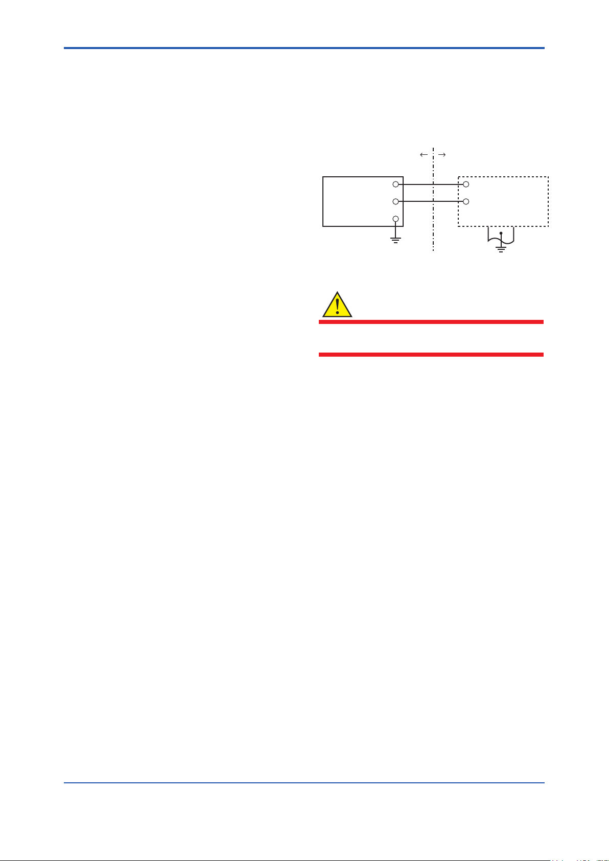
[Installation Diagram]
Hazardous Location
Transmitter
+
Supply
–
*1: In any safety barriers used the output current must be
limited by a resistor “R” such that Imaxout-Uz/R.
WARNING
Nonhazardous Location
+
Safety Barrier
–
F0206r.ai
To satisfy IP66 or IP67, apply waterproof glands
to the electrical connection port.
b. ATEX Flameproof Type
Caution for ATEX ameproof type.
Note 1. Model EJX Series pressure transmitters
with optional code /KF21 for potentially
explosive atmospheres:
• No. KEMA 07ATEX0109
• Applicable Standard: EN 60079-0:2006,
EN 60079-1:2004, EN 61241-0:2006,
EN 61241-1:2004
• Type of Protection and Marking Code: Ex d
IIC T6...T4, Ex tD A21 IP6x T85, T100, T120
• Group: II
• Category: 2G, 2D
• Enclosure: IP66 and IP67
• Temperature Class for gas-poof:
T6, T5, and T4
• Ambient Temperature for gas-proof:
–50 to 75°C (T6), –50 to 80°C (T5), and
–50 to 75°C (T4)
• Maximum Process Temperature (Tp.) for
gas-proof:
85°C (T6), 100°C (T5), and 120°C (T4)
• Maximum Surface Temperature for dustproof:
T85°C (Tamb.: –40* to 40°C, Tp.: 80°C)
T100°C (Tamb.: –40* to 60°C, Tp.: 100°C)
T120°C (Tamb.: –40* to 80°C, Tp.: 120°C)
* –15°C when /HE is specied.
*1
Page 3

Note 2. Electrical Data
• Supply voltage: 42 V dc max.
• Output signal: 4 to 20 mA
Note 3. Installation
• All wiring shall comply with local installation
requirement.
• The cable entry devices shall be of a certied
ameproof type, suitable for the conditions of
use.
Note 4. Operation
• Keep the “WARNING” label attached to the
transmitter.
WARNING: AFTER DE-ENERGIZING,
DELAY 5 MINUTES BEFORE OPENING.
WHEN THE AMBIENT TEMP.≥65°C, USE
HEAT-RESISTING CABLES≥90°C.
• Take care not to generate mechanical
sparking when accessing to the instrument
and peripheral devices in a hazardous
location.
Note 5. Maintenance and Repair
• The instrument modication or part
replacement by other than an authorized
representative of Yokogawa Electric
Corporation is prohibited and will void KEMA
Flameproof Certication.
WARNING
To satisfy IP66 or IP67, apply waterproof glands
to the electrical connection port.
(3) Installation
WARNING
• All wiring shall comply with local installation
requirements and the local electrical code.
• There is no need for conduit seal in Division
1 and Division 2 hazardous locations
because this product is sealed at the factory.
(4) Operation
WARNING
• OPEN CIRCUIT BEFORE REMOVING
COVER. INSTALL IN ACCORDANCE WITH
THIS USER’S MANUAL
• Take care not to generate mechanical
sparking when access to the instrument and
peripheral devices in a hazardous location.
(5) Maintenance and Repair
WARNING
The instrument modication or parts replacement
by other than an authorized Representative of
Yokogawa Electric Corporation is prohibited and
will void the certication.
(6) Name Plate
(2) Electrical Connection
A mark indicating the electrical connection type
is stamped near the electrical connection port.
These marks are as followed.
Screw Size Marking
ISO M20 × 1.5 female
ANSI 1/2 NPT female
M
A or WN or
Location of the mark
F0208r.ai
● Name plate
● Tag plate for flameproof type
No. KEMA 07ATEX0109
Ex d IIC T6...T4, Ex tD A21, IP6X
Enlcosure : IP66, IP67
TEMP. CLASS T6 T5 T4
MAX PROCESS TEMP.(Tp.) 85 100 120 °C
Tamb. -50(-15) to 75 80 75 °C
T85°C(Tamb.:40°C, Tp.:80°C),T100°C(Tamb.:60°C, Tp.:100°C),
T120°C(Tamb.:80°C, Tp.:120°C) Min.Tamb.:-40(-15)°C(for Dust)
D
WARNING
AFTER DE-ENERGIZING, DELAY 5 MINUTES
BEFORE OPENING.
WHEN THE AMBIENT TEMP. ≥ 65°C,
USE THE HEAT-RESISTING CABLES ≥ 90°C
● Tag plate for intrinsically safe type
No. KEMA 03ATEX1544 X
EEx ia IIC T4
IP66 and IP67
Tamb. -50(-15) to 60°C MIN. Tamb.:-40(-15)°C(for DUST)
MAX. PROCESS TEMP.(Tp.) 120°C
T85°C(Tp.:80°C), T100°C(Tp.:100°C), T120°C(Tp.:120°C)
Ui=30V, Ii=200mA , Pi=0.9W, Ci=10nF, Li=0
D
F0209r.ai
Page 4

MODEL: Specied model code.
91K819857 032
STYLE: Style code.
SUFFIX: Specied sufx code.
SUPPLY: Supply voltage.
OUTPUT: Output signal.
MWP: Maximum working pressure.
CAL RNG: Specied calibration range.
NO.: Serial number and year of production*1.
TOKYO 180-8750 JAPAN:
The manufacturer name and the address*2.
*1: The rst digit in the nal three numbers of the serial
*2: “180-8750” is a zip code which represents the
number appearing after “NO.” on the nameplate
indicates the year of production. The following is an
example of a serial number for a product that was
produced in 2010:
The year 2010
following address.
2-9-32 Nakacho, Musashino-shi, Tokyo Japan
 Loading...