

Page 1

User ’s
Manual
IM CA71-E
Model CA51, CA71
HANDY CAL
(Calibrator)
Store this manual in an easily accessible
place for quick reference.
10th Edition: Nov. 2018 (YMI)
IM CA71-E
Page 2

Introduction
Thank you for purchasing the CA51/CA71 HANDY CAL Calibrator.
This User’s Manual explains the functions of the CA51 and CA71,
as well as the operating methods and handling precautions.
Before using this product, thoroughly read this manual to
understand how to use it properly.
■ List of Manuals
The following manuals, including this one, are provided as manuals
for the CA51 and CA71. Please read all manuals.
Manual No. Description
IM CA71-E User's Manual (this manual)
IM CA71-93Z2 Document for Korea
Contact information of Yokogawa ofces worldwide is provided on
the following sheet.
Document No. Description
PIM 113-01Z2 Inquiries List of worldwide contacts
10th Edition: November 2018 (YMI)
All Rights Reserved. Copyright © 2002, Yokogawa M&C Corporation,
2014, Yokogawa Meters & Instruments Corporation,
2017, Yokogawa Test & Measurement Corporation
Printed in Japan
IM CA71-E
i
Page 3

Introduction
■ Notes
● This manual exclusively describes the CA71, which is more
multifunctional than the CA51. The CA51 has no temperature
measurement and communication functions.
● The contents of this manual are subject to change without prior
notice for reasons of improvements in performance and/or
functionality.
● Every effort has been made to ensure the accuracy of this manual.
If you notice any errors or have any questions, however, please
contact the vender from which you purchased the instrument.
● The content of this manual may not be transcribed or reproduced,
in part or in whole, without prior permission.
■ Trademark Acknowledgments
● All other company and product names appearing in this document
are trademarks or registered trademarks of their respective holders.
■ Revision Information
February 2002: First Edition
December 2006: 2nd Edition
November 2007: 3rd Edition
January 2012: 4th Edition
July 2014: 5th Edition
April 2015: 6th Edition
April 2016: 7th Edition
August 2017: 8th Edition
October 2017: 9th Edition
November 2018: 10th Edition
ii
IM CA71-E
Page 4

Checking Items in the Package
After opening the package, check the product as follows before use.
If the delivered product is the wrong model, any item is missing,
or there are visible defects, contact the vendor from which you
purchased the product.
Main Unit
Check the model (specications) codes in the MODEL and SUFFIX
elds of the nameplate at the back of the instrument to ensure that
the instrument is exactly as specied in your purchase order.
• Model Codes
Model Specication
CA51 Basic model
CA71 Provided with temperature measurement and
communication functions
• NO. (Serial Number)
Refer to this serial number on the nameplate when contacting
the vendor about the instrument.
IM CA71-E
iii
Page 5

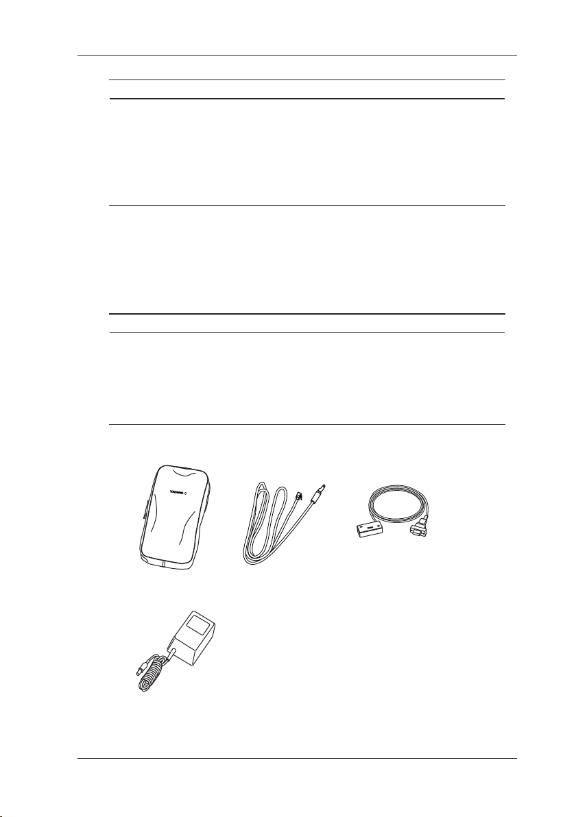
Checking Items in the Package
Lead cables
Lead cables for
Carrying case
Terminal adapter
Standard Accessories
Make sure that the package contains all the accessories listed below
and that they are all free from any damage.
Standard accessories are not covered by warranty of this instrument.
for source
(98020)
(99021)
measurement
(RD031)
AA-size (LR6)
alkaline batteries
(four units)
(93016)
User’s manual
(IM CA71-E)
Optional Accessories
The products listed below are available as optional accessories.
If you purchased some of the optional accessories,
make sure the delivered package is complete with
the ordered items and they are free from any damage.
For technical and ordering inquiries concerning the accessories,
contact the vendor from which you purchased the instrument.
iv
IM CA71-E
Page 6
Accessories case
RJ sensor Communication cable
Checking Items in the Package
Product Part Number Remarks
AC adapter 94012 For 100 VAC
AC adapter 94013 For 120 VAC
AC adapter 94016 For 220 to 240 VAC
RJ sensor B9108WA For reference junction compensation
Accessories case B9108XA
Communication cable
(RS232)
91017 (For CA71 only)
Power cord of AC adapter:
94016-F (VDE standard), 94016-S (BS stanndard)
Make sure that the attached power cord meets the designated
standards of the country and area that you are using it in.
Optional Spare Parts
Product Part Number Remarks
Lead cable for source 98020
Lead cable
for measurement
Carrying case 93016
Terminal adapter 99021 Used for temperature measurement
Fuse --- A1635EF (1 piece)
RD031
IM CA71-E
AC adapter
v
Page 7

Precautions for Safe Use of the Instrument
This product is designed to be used by a person with specialized
knowledge.When operating the instrument, be sure to observe
the cautionary notes given below to ensure correct and safe use of
the instrument. If you use the instrument in any way other than as
instructed in this manual, the instrument’s protective measures may
be impaired. This manual is an essential part of the product;
keep it a safe place for future reference.
YOKOGAWA is by no means liable for any damage resulting from
use of the instrument in contradiction to these cautionary notes.
The following symbols are used on the instrument and in
the User’s Manual to ensure safe use.
Danger! Handle with Care.
This symbol indicates that the operator must refer to
an explanation in the User’s Manual in order to avoid
the risk of injury or loss of life of personnel or damage to
the instrument.
This symbol indicates DC voltage/current.
This symbol indicates AC voltage/current.
This symbol indicates AC or DC voltage/current.
WARNING
Indicates that there is a possibility of serious personal injury or loss of life
if the operating procedure is not followed correctly and describes
the precautions for avoiding such injury or loss of life.
CAUTION
Indicates that there is a possibility of serious personal injury or damage to
the instrument if the operating procedure is not followed correctly and
describes the precautions for avoiding such injury or damage.
vi
IM CA71-E
Page 8
Precautions for Safe Use of the Instrument
NOTE
Draws attention to information essential for understanding the operation
and features.
TIP
Provides additional information to complement the present topic.
Damage to the instrument or personal injury or even loss of life
may result from electrical shock or other factors.
To avoid this, follow the precautions below.
WARNING
• Use the instrument Only for Its Intended Purpose
This instrument is for generating (sourcing)/measuring voltage or current.
(This instrument is for generating and measuring resistance and
generating and measuring temperature using resistance or thermocouples.)
Do not use this instrument for other purpose.
• Check the Physical Appearance
Do not use the instrument if there is a problem with its physical appearance.
• Use in gases
Do not operate this instrument in areas where inammable or explosive
gases or vapor exists.
It is extremely hazardous to use the instrument under such environments.
• Defects in protective features
Do not operate this instrument if any defect seems to exist in such protective
features as fuses.
Before operating the instrument, make sure the protective features are free
from any defect.
• External connection
When connecting the instrument to the object under test or an external
control circuit, or if you need to touch any external circuit, cut off the power
to the circuit and make sure no voltage is being supplied.
• Fuses
In order to prevent a possible re, use a fuse with ratings (current, voltage,
and type) specied for the instrument. Do not short-circuit the fuse holder.
IM CA71-E
vii
Page 9

Precautions for Safe Use of the Instrument
WARNING
• Correct Use of Lead Cables
Use the lead cables supplied by YOKOGAWA with this instrument.
Do not use lead cables that have deteriorated or are defective.
Check lead cables continuity.
Correctly use the lead cables for measurement (P/N: RD031) and
source (P/N: 98020) without mistaking one for the other.
For high-voltage measurement, always use the lead cable for measurement.
• Damaged Signal Cable
If the signal cable (lead cables) is torn and the inner metal is exposed or
if a color different from the outer sheath appears, stop using the cable
immediately.
• Do Not Remove the Casing or Disassemble
Only Yokogawa service personnel are authorized to remove the casing or
disassemble or modify the instrument.
Do not attempt to repair the instrument yourself, as doing so is extremely
dangerous. Some parts inside the instrument are extremely dangerous
because they use a high voltage.
When the instrument needs an internal inspection or calibration,
contact YOKOGAWA or the dealer from whom you purchased the instrument.
CAUTION
This product is for domestic use (Class B) and meets the electromagnetic
compatiblity requirements.
viii
IM CA71-E
Page 10

Precautions for Safe Use of the Instrument
For the safe use of the optional AC adapter, follow the precautions
given below.
WARNING
• Make sure that the rated power supply voltage of the instrument matches
the voltage of the power supply before turning on the power.
• To prevent the possibility electrical shock or re, be sure to use
the AC adapter and the power cord supplied by YOKOGAWA.
Additionally, do not use the AC adapter and the power cord supplied with
this instrument with another instrument.
• Do not place anything on the AC adapter or power cord, and prevent heat
sources from coming into contact with them.
• When unplugging the power cord from the outlet, be sure to hold the plug
and never pull the actual cord.
• Do not throw (dispose of ) the AC adapter in re or apply heat to it.
• Do not use it, where the cord is bundled (bent).
• If the power cord is damaged, contact your dealer.
IM CA71-E
ix
Page 11

Contents
Introduction ..........................................i
Checking Items in the Package .........................iii
Precautions for Safe Use of the Instrument ...............vi
1. Functions .......................................1-1
2. Names and Functions of Parts .....................2-1
3. Before Starting Source/Measurement ................3-1
4. Source .........................................4-1
4.1 Connecting Cables to Terminals.......................4-2
4.2 Sourcing DC Voltage, DC Current or
SINK Current Signal ................................4-3
4.2.1 Sourcing DC Voltage or DC Current Signal ........4-3
4.2.2 4-20 mA Function ............................4-4
4.2.3 20 mA SINK Function .........................4-5
4.2.4 Using As 24-V Loop Power Supply ..............4-6
4.3 Sourcing Resistance or RTD Signal ....................4-7
4.4 Sourcing Thermocouple (TC) Signals...................4-9
4.4.1 When RJ Sensor Is Used
(Making Use of Reference Junction Compensation)
4.4.2 When No RJ Sensor Is Used ..................4-12
4.5 Sourcing Pulse Signals.............................4-13
4.5.1 Sourcing a Continuous Pulse Train .............4-13
4.5.2 Sourcing the Preset Number of Pulses
(Pulse Cycle) ..............................4-15
4.5.3 Using the Contact Output.....................4-17
4.6 Divided Output Function (n/m) .......................4-19
4.7 Sweep Function ..................................4-20
4.8 Auto Step Function ................................4-20
4.9 Temperature Monitor Function .......................4-21
...4-9
x
IM CA71-E
Page 12

Contents
5. Measurement ....................................5-1
5.1 Connecting Cables to Terminals .......................5-2
5.2 Measuring 300 V AC-range Voltage,
DC Voltage, AC Voltage or DC Current .................5-4
5.2.1 Measuring 300 V AC-range Voltage..............5-4
5.2.2 Measuring DC or AC Voltage ...................5-5
5.2.3 Measuring DC Current ........................5-5
5.3 Measuring Resistance or RTD (CA71 only) Signal.........5-6
5.4 Measuring Temperature with
Thermocouple (TC) - CA71 only -......................5-7
5.5 Measuring Frequency or Pulses.......................5-8
5.5.1 Operating the Calibrator for Frequency
Measurement...............................5-8
5.5.2 Operating the Calibrator for Measuring Number of
Pulses ....................................5-8
6. Memory Functions ...............................6-1
6.1 Saving Data into Memory ............................6-2
6.1.1 Saving Data in the Order of Memory Numbers .....6-2
6.1.2
Saving Data by Selecting Desired Memory Number
6.1.3 Overwriting Data in Memory....................6-4
6.2 Reading Data from Memory . . . . . . . . . . . . . . . . . . . . . . . . . . 6-5
6.3 Clearing Data in Memory ............................6-6
6.3.1 Clearing Data by Selecting Desired
Memory Number ............................6-6
6.3.2 Clearing All In-Memory Data Globally ............6-7
6.4 Sending Out Data from Memory
- CA71 only -......................................6-7
7. Functions Provided by DIP Switch ..................7-1
7.1 Sweep Function ...................................7-2
7.2 Auto Step Function .................................7-4
7.3 Selecting the INT RJ Function ........................7-6
7.4 Selecting the IPTS-68 Function .......................7-7
7.5 Switch Not Used ...................................7-7
7.6 Temp Switch ......................................7-7
7.7 Selecting the Contact In Function
(Contact Input for Pulse Measurement) .................7-7
...6-4
1
2
3
4
5
6
7
8
9
10
11
12
13
App
IM CA71-E
xi
Page 13

Contents
8. Communication Function - CA71 only - ..............8-1
8.1 Cables Connection and Interface Specications ..........8-1
8.2 Setting the Mode...................................8-2
8.3 Types of Mode ....................................8-2
8.4 Data Format ......................................8-3
8.5 Data Structure.....................................8-3
8.6 Commands .......................................8-4
8.7 Detailed Description of Commands ....................8-5
9. Troubleshooting and Calibration....................9-1
10. Method of Calibrator Adjustment ..................10-1
10.1 Calibration Standard Selection and
Environmental Requirements ........................10-1
10.2 Adjusting Source Functions .........................10-3
10.3 Adjusting Measurement Functions ....................10-6
10.3.1 Adjusting DC Voltage and DC Current Ranges ....10-6
10.3.2 Adjusting AC Voltage and Resistance
(400 Ω) Ranges ............................10-8
10.4 Notes on the Adjustment of
Temperature Ranges - CAL71 only - ..................10-9
10.5 Post-adjustment Verication .........................10-9
11. Using Accessories ..............................11-1
12. Specications ..................................12-1
13. Sales in Each Coutry or Region....................13-1
13.1 Disposing the Product..............................13-1
13.2 How to Replace and Dispose the Batteries .............13-1
13.3 Authorized Representative in the EEA . . . . . . . . . . . . . . . . . 13-2
13.4 For the Pollution Control of Electronic
and Electrical Products of the People's
Republic of China .................................13-3
Appendix 1 Reference Junction Compensation .......... App1-1
xii
IM CA71-E
Page 14
1. Functions
Temperature
3Wire
AC adapter
MEASURE
■ Block Diagram
H
SOURCE
Pulse
source
Output on/off relay
D/A
converter
Multiplying
V
Ω
mA
SOURCE Mode
Section
Reference
voltage
L
Overcurrent
detection
V
Ω
mA
Current-to-voltage
conversion
Setting
Display
RJ INPUT
Temperature
A/D
converter
CPU
sensor
Communication
cable
DIP switch
Memory
1
Functions
IM CA71-E
A/D
MEASURE Mode
Section
RJ
detection
circuit
Input
voltage
selector &
Constant
current
source
Ω
H
converter
divider
sensor
L
Shunt resistor
3W
FUSE mA
mA
DC/DC
converter
Measurement mode
on/off switch
Power
supply
circuit
Batteries
Power-on/off switch
AC100V
1-1
Page 15

1. Functions
■ Main Functions
• Source
The calibrator sources a voltage, current, resistance, thermocouple
(TC), RTD, frequency or pulse signal at a preset level.
Function Description
DC voltage Sources a DC voltage signal in the 100 mV, 1 V, 10 V or
30 V range.
DC current Sources a DC current signal in the 20 mA range.
SINK current Draws a sink current from an external power source in
the 20 mA range.
Resistance Sources a resistance signal in the 400 Ω range.
Thermocouple (TC) Sources a thermoelectromotive force corresponding to
the temperature detected by a type-K, E, J, T, R, B, S, N, L
or U thermocouple.
RTD Sources resistance corresponding to the temperature
detected by a Pt100 or JPt100 RTD.
Frequency and
pulse
*1: The thermocouples comply with the Japanese Industrial Standard
JIS C1602 (ITS-90), except for the type-L and U thermocouples
that comply with DIN.
Sources a continuous pulse train with frequency in
the 500 Hz, 1 kHz or 10 kHz range.
This function also sources the preset number of pulses
dened by the frequency mentioned above.
*1
*2
*2: The RTD comply with the Japanese Industrial Standard JIS C1604 (ITS-90).
The internal DIP switch can be congured so that the detectors comply with
IPTS-68 instead.
1-2
IM CA71-E
Page 16

1. Functions
• Measurement
Independent of the source function, the calibrator measures
DC voltage, AC voltage, DC current and resistance signals,
a temperature signal based on a thermocouple (TC) or RTD,
as well as frequency and the number of pulses.
Function Description
DC voltage Measures a DC voltage signal in the 100 mV, 1 V, 10 V or
100 V range.
AC voltage Measures a DC voltage signal in the 1 V, 10 V, 100 V or
300 V range.
DC current Measures a DC current signal in the 20 mA or 100 mA
range.
The current terminals are equipped with a built-in
overrange input protection fuse.
Resistance Measures a resistance signal in the 400 Ω range.
Thermocouple (TC) Measures temperature according to the type of
thermocouple – K, E, J, T, R, B, S, N, L or U.
RTD Measures temperature according to the type of
RTD – Pt100 or JPt100.
Frequency and
pulse
Measures frequency in the 100 Hz, 1 kHz or 10 kHz range.
For pulse signals, this function measures the number of
pulses as a CPM (count per minute) or CPH (count per
hour) reading.
*2
(CA71 only)
*1
(CA71 only)
1
Functions
You can also select and congure the following functions.
Function Description
Divided output
function (n/m)
Memory Stores up to 50 sourced and measured values as a set.
Sweep Changes the output signal in a linear manner.
Auto step Automatically changes the value of n in a setpoint × n/m
IM CA71-E
Sources a “setpoint × (n/m)” output signal,
where the variables m and n are dened as
m = 1 to 19 and n = 0 to m.
output in a step-by-step manner.
1-3
Page 17

1. Functions
• Power Supply
The calibrator operates on AA-size (LR6) alkaline batteries or
the optional AC adapter.
1-4
IM CA71-E
Page 18

1
2. Names and Functions of Parts
5
MEASURE
SOURCE
3 4
2
Names and Functions of Parts
6
7
1 98 17 1521116 14
20
181910
12
13
21
22
23
24
IM CA71-E
2-1
Page 19

2. Names and Functions of Parts
■ Front Panel
1) POWER Key
Turns on/off the power supply.
2) LIGHT Key
Turns on/off the backlight of the LCD.
MEASURE Mode – Functions for Measurement
3) DC Voltage, AC Voltage, Resistance and Pulse Input Terminals
Serve as H (positive) and L (negative) input terminals when
you measure DC voltage, AC voltage, resistance, and pulse signals.
4) DC Current Input Terminals
Serve as H (positive) and L (negative) input terminals when
you measure a DC current signal. Also serve as L’ terminals when
you carry out 3-wire resistance measurement.
5) Three-wire Input Terminals
6) Function Selector Switch
Selects a measurement function and its range.
7) RANGE DC/AC Key
Used to further select from range options within the selected function.
• If you have selected the 1 V, 10 V or 100 V range, use this key to
toggle between the DC and AC options.
• If you have selected the FREQ range, use this key to select
the range of frequency measurement, as the key cycles through
the 100 Hz, 1 kHz, 10 kHz, CPM and CPH options.
• If you have selected the mA range, use this key to select from
the 20 mA and 100 mA ranges.
• If you have selected the 100 mV TC range, use this key to select
the voltage range or the type of thermocouple, as the key cycles
through the 100 mV, K, E, J, T, R, B, S, N, L and U options.
(CA71 only)
• If you have selected the Ω RTD range, use this key to select
the resistance range or the type of RTD, as the key cycles through
the 400 Ω, Pt100 and JPt100 options. (CA71 only)
If you have selected the TC or RTD range in the source mode of
display, the TC or RTD type options on the SOURCE function side
precede those on the MEASURE mode side.
2-2
IM CA71-E
Page 20

1
2. Names and Functions of Parts
8) MEASURE OFF Key
Turns on/off the MEASURE mode. Turning off the mode causes
the measured value shown on the LCD to disappear.
If the MEASURE mode is not in use and therefore turned off,
the power to the measurement circuit within the calibrator is also
turned off.
This strategy saves on battery power if the calibrator is running on
batteries.
9) HOLD Key
Holds the measured value being displayed.
Also used to start CPM or CPH measurement or communication.
10) MEM Key
Used to turn on/off the memory function.
SOURCE Mode – Functions for Generation
11) Output Terminals
These terminals are common to all of the source functions.
12) Function Selector Switch
Selects a source function and its range.
13) RANGE Key
Used to further select from range options within the selected function.
• If you have selected the 100 mV TC range, use this key to select
the voltage output or the type of thermocouple, as the key cycles
through the 100 mV, K, E, J, T, R, B, S, N, L and U options.
• If you have selected the 400 Ω RTD range, use this key to select
the resistance range or the type of RTD, as the key cycles through
the 400 Ω, Pt100 and JPt100 options.
• If you have selected the PULSE range, use this key to select
the frequency range, as the key cycles through the 500.0 Hz,
1000 Hz and 10 kHz options.
14) SOURCE ON Key
Turns on/off the source output.
15) PULSE SET Key
If you have selected the PULSE range, use this key to cycle through
the frequency, amplitude and pulse count options for pulses being
generated.
2
Names and Functions of Parts
IM CA71-E
2-3
Page 21
2. Names and Functions of Parts
16) TEMP Key
Allows you to monitor temperature by selecting from the room
temperature (°C), reference junction temperature (°C),
thermocouple (mV) and RTD (Ω) options.
17) n/m Key
Turns on/off the divided output function (n/m).
and Output Setting Keys
18)
Set the output value of a source function.
Each pair of
and keys corresponds to each digit of
the reading, thus increasing/decreasing the digit in units of 1s.
Increasing the digit from 9 or decreasing it from 0 causes the digit to
overow or underow, allowing you to set the output value without
interruption.
Holding down the
question.
If your choice is the 4–20 mA function, see Section 4.2, “Sourcing
DC Voltage, DC Current or SINK Current Signal,” for further details.
Note that
• The
and keys are also used in the following ways:
and keys labeled n and m serve as keys for setting
the variables n and m when you have selected the divided output
function (n/m).
(See Section 4.6, “Divided Output Function (n/m),” for further details.)
• The and keys labeled MEM NO., SAVE and READ serve
as keys for working with the memory when you have selected
the memory function.
(See Chapter 6, “Memory Function,” for further details.)
19) CLEAR Key
Initializes the output setpoint, causing the on-screen reading to
revert to 0000 for functions other than PULSE and 20 mA SINK,
though the number of digits depends on function selected.
This key serves as a key for clearing the memory when the memory
function is selected.
or key continuously changes the digit in
2-4
IM CA71-E
Page 22
1
b
i jg h
a
k
2. Names and Functions of Parts
■ Side and Rear Panels
20) FUSE
A holder for housing a fuse that protects the input during DC
current measurement.
21) R.J.INPUT
A connector to which the external reference junction compensation
sensor is connected.
22) AC Adapter Connection Jack
23) Battery Holder
Opening the cover reveals the battery holder and DIP switch.
24) I/O Port Cover
Open this cover to connect the RS232 communication cable
(P/N: 91017). (CA71 only)
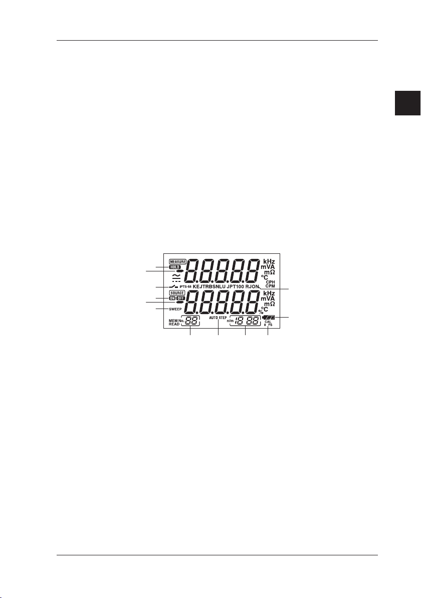
■ LCD Unit
c
2
Names and Functions of Parts
d
e
f
a) Measured value
b) Setpoint for source
c) HOLD indicator
Indicates the on-screen measured value is in a hold state.
d) Contact input
Indicates the contact input is selected when your choice is pulse
measurement.
e) ON/OFF indicators for output
ON: Indicates the output is on.
OFF: Indicates the output is off.
f) SWEEP indicator for sweep function
Comes on when the sweep function is selected using the DIP switch.
IM CA71-E
l
2-5
Page 23

2. Names and Functions of Parts
g) MEM NO. indicator
Shows a memory number when the memory function is selected.
h) AUTO STEP indicator
Comes on when the auto step function is selected.
i) Divided output function (n/m) indicator
Comes on when the divided output function (n/m) is selected.
The most signicant two digits “18” denote the value of n,
while the least signicant two digits “88” mean the value of m.
j) CAL mode selection indicator
The 0 and FS indicators below this indicator denote zero point and
full scale adjustments, respectively.
k) Battery replacement indicator
(Remaining battery power indicator)
Shows the battery level in three steps according to the level of
remaining electricity.
l) RJON indicator
Indicates reference junction compensation is active when
thermoelectromotive force is being sourced.
The thermoelectromotive force output when this indicator is off
represents the 0°C-based output.
2-6
IM CA71-E
Page 24

1
2
3. Before Starting Source/Measurement
■ Operating Precautions
Precautions for Safe Use of the Instrument
● When using the instrument for the rst time, be sure to read
the instructions given on pages vi to ix of the section,
“Precautions for Safe Use of the Instrument.”
● Do not open the instrument’s case.
Opening the case is extremely hazardous, as the instrument contains
high-voltage parts. Contact the vendor from which you purchased
the instrument, for a service of inspecting or adjusting the internal
assembly.
● In case of failure
Should the instrument begin to emit smoke, give off an unusual odor,
or show any other anomaly, immediately turn off the POWER key.
If you are using an AC adapter, disconnect the plug from the wall outlet.
Also cut off power to the object under test that is connected to
the input terminals. Then, contact the vendor from which you purchased
the instrument.
General Handling Precautions
● Before carrying around the instrument turn off power to the object
under test, and then the POWER key of the instrument.
If you are using an AC adapter, disconnect the power cord from
the wall outlet. Finally, detach all lead cables from the instrument.
Use a dedicated carry case when transporting the instrument.
● Do not bring any electried object close to the input terminals,
since the internal circuit may be destroyed.
● Do not apply any volatile chemical to the instrument’s case or
operation panel. Do not leave the instrument in contact with any
product made of rubber or vinyl for a prolonged period.
Be careful not to let a soldering iron or any other heat-emitting object
come into contact with the operation panel, as the panel is made of
thermoplastic resin.
● Before cleaning the instrument’s case or operation panel disconnect
the power cord plug from the wall outlet if you are using an AC adapter.
Use a soft, clean cloth soaked in water and tightly squeezed to gently
wipe the outer surfaces of the instrument.
Ingress of water into the instrument can result in malfunction.
3
Before Starting Source/Measurement
IM CA71-E
3-1
Page 25

3. Before Starting Source/Measurement
● If you are using an AC adapter with the instrument and will not use
the instrument for a prolonged period, disconnect the power cord plug
from the wall outlet.
● For handling precautions regarding the batteries, see “Installing or
Replacing the Batteries” on page 3-3.
● Never use the instrument with the cover of the battery holder opened.
Operating Environment and Conditions
This instrument complies with the EMC standard under specic
operating environment and operating conditions.
If the installation, wiring, and so on are not appropriate, the compliance
conditions of the EMC standard may not be met.
In such cases, the user will be required to take appropriate measures.
■ Environmental Requirements
Use the instrument in locations that meet the following
environmental requirements:
• Ambient temperature and humidity
Ambient temperature range: 0 to 50°C
Ambient humidity range: 20 to 80% RH.
Use the instrument under non-condensing condition.
• Flat and level locations
• Indoors
• Operating altitude: 2000 m or less
3-2
Do not use the instrument in locations that are:
• Outdoors
• exposed to direct sunlight or close to any heat source;
• exposed to water or other liquids;
• exposed to frequent mechanical vibration;
• close to any noise source, such as high-voltage equipment or
motive power sources;
• close to any source of intensive electric or electromagnetic elds;
• exposed to large amounts of greasy fumes, hot steam, dust or
corrosive gases;
• unstable; or
• exposed to a risk of explosion due to the presence of ammable
gases.
IM CA71-E
Page 26

1
2
3. Before Starting Source/Measurement
NOTE
• Use the instrument under the following environmental conditions if precise
source or measurement is your requirement:
Ambient temperature range: 23±5°C; ambient humidity range: 20 to 80% RH
(non-condensing)
When using the instrument within a temperature range of 0 to 18°C or
28 to 50°C, add a value based on the temperature coefcient shown in
Chapter 12, “Specications (page 12-1),” to the given accuracy rating.
• When using the instrument at an ambient humidity of 30% or lower, prevent
electrostatic charges from being produced, by using an antistatic mat or any
other alternative means.
• Condensation may occur if you relocate the instrument from places with
low temperature and humidity to places with high temperature and humidity,
or if the instrument experiences any sudden temperature change.
In that case, leave the instrument under the given ambient temperature for
at least one hour to ensure that the instrument is free from condensation,
before using the instrument.
■ Installing or Replacing the Batteries
WARNING
3
Before Starting Source/Measurement
To avoid electrical shock, always remove the source or measurement lead
cables from the object under test, as well as from the instrument itself.
CAUTION
• To avoid the risk of uid leakage or battery explosion, install batteries with
their positive and negative electrodes correctly positioned.
• Do not short-circuit the batteries.
• Do not disassemble or heat the batteries or throw them into re.
• When replacing batteries, replace all of the four batteries at the same time
with new ones from the same manufacturer.
• If the instrument will not be used for a prolonged period, remove the batteries
from the instrument.
IM CA71-E
3-3
Page 27
3. Before Starting Source/Measurement
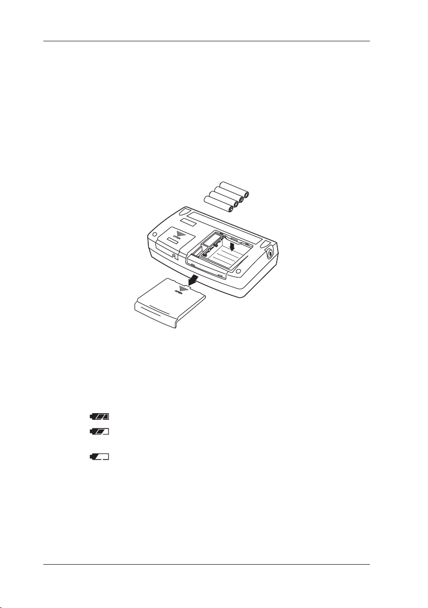
Step 1: Remove the lead cables and AC adapter and turn off
the calibrator before you begin installing batteries.
Step 2: Remove the battery holder cover by sliding it in the direction
indicated by → OPEN.
Step 3: Install four AA-size (LR6) alkaline batteries in the battery
holder with their positive and negative electrodes positioned
correctly as indicated on the holder.
Step 4: After replacement, reattach the battery holder cover tightly.
OPEN
3-4
Indication of Battery Level
(Remaining Battery Power Indicator)
The battery replacement indicator shows the battery level in three
steps according to the measured voltage of the batteries.
(Lit constantly): The battery level is normal.
(Lit constantly): The battery level is below 50% full,
but still allows for normal operation.
(ashing): replace the batteries.
IM CA71-E
Page 28
1
2
3. Before Starting Source/Measurement
Note that the battery replacement (remaining battery power)
indicator is driven by directly measuring the battery voltage
when the calibrator is in actual operation.
Consequently, the indicator may read differently depending on
the battery load condition (e.g., the load condition of the source
output or on/off state of the measurement function)
if the batteries are too low.
If the remaining power starts to run low, replace the batteries
as soon as possible.
If the calibrator will be used under a wide variety of conditions,
it is advisable that the battery replacement indicator be veried
under heavy loads (MEASURE mode is on and the SOURCE mode
is set to the 20 mA/10 V output).
■ Connecting the AC Adapter
WARNING
• Make sure that the rated power supply voltage of the instrument matches
the voltage of the power supply before turning on the power.
• To prevent the possibility electrical shock or re, be sure to use
the AC adapter and the power cord supplied by YOKOGAWA.
Additionally, do not use the AC adapter and the power cord supplied with
this instrument with another instrument.
• Do not place anything on the AC adapter or power cord, and prevent heat
sources from coming into contact with them.
• When unplugging the power cord from the outlet, be sure to hold the plug
and never pull the actual cord.
• Do not throw (dispose of ) the AC adapter in re or apply heat to it.
• Do not use it, where the cord is bundled (bent).
• If the power cord is damaged, contact your dealer.
3
Before Starting Source/Measurement
Step 1: Make sure the calibrator is turned off.
Step 2: Insert the plug of the optional AC adapter into the AC adapter
connection jack.
IM CA71-E
3-5
Page 29

3. Before Starting Source/Measurement
■ Turning On/Off the Power
CAUTION
To verify the instrument's functionality, check that the measured value is
updated after turning on the power. If the measured value is not updated,
the reading will be incorrect and may lead to possible electrical shock or
personal injury.
Turning On/Off the POWER Switch
Pressing the
Pressing the
key once when the power is off turns on the calibrator.
key once again turns off the calibrator.
NOTE
• Before disconnecting the AC adapter from an AC power source,
turn off the calibrator by pressing the
• When operating the calibrator on batteries, disconnect the AC adapter
plug from the instrument.
Once you connect the AC adapter plug to the instrument, the instrument no
longer operates on batteries.
Thus, the instrument will not turn on unless the AC adapter is connected
to an AC power source.
• Be sure to turn off the POWER switch when you nish using the instrument.
key.
3-6
IM CA71-E
Page 30

1
2
3. Before Starting Source/Measurement
Turning On/Off MEASURE Mode
Pressing the
mode.
• If the MEASURE mode is not needed and therefore turned off,
power to the measurement circuit is also turned off within
the calibrator.
Thus, you can save on battery power if the calibrator is running on
batteries.
• Turning off the MEASURE mode causes the on-screen measured
value to disappear.
• To resume measurement when the MEASURE mode is off,
press the
TIP
One to two seconds are taken for the LCD to turn on after the MEASURE
mode is turned on.
key after power-on turns off the MEASURE
key once again.
■ Turning On/Off the Backlight
The LCD can be back-lit. Pressing the key turns on the backlight,
while pressing the key once again turns it off.
This feature makes it easier for you to view the LCD when operating
the calibrator in dark places or when carrying out source or
measurement.
Note that battery life shortens when the calibrator is operated on
batteries.
3
Before Starting Source/Measurement
NOTE
The backlight automatically turns off approximately one minute later.
To turn on the backlight again, press the
key once again.
IM CA71-E
3-7
Page 31

3. Before Starting Source/Measurement
■ Operating Environment
Operating Environment
Ambient Temperature and Humidity
Use the CA51/71 in the following environment:
• Ambient temperature: 0 to 50°C
• Ambient humidity: 20 to 80 % RH (no condensation)
• Location: indoors
• Operating altitude: 2000 m max. above sea level.
■ Measurement Category
Measurement Category of Main unit
WARNING
The instrument is designed for measurement category III.
Do not use the CA51 or CA71 for measurements in location that fall
under Measurement Category IV.
Measurement
Category
O
(None, Other)
CAT II
CAT III
CAT IV
Description Remarks
Other circuits that are not directly
connected to MEAINS.
For measurement preformed on
circuits directly connected to a
low-voltage installation.
For measurement preformed in a
building installation.
For measurement preformed at the
source of a low-voltage installation.
Circuits not connected to
a mains power source.
Appliances, portable
equipment, etc.
Distribution board,
circuit breaker, etc.
Overhead wire,
cable systems, etc.
Category of Lead cables (RD031)
WARNING
When you use the lead cables, attache or remove the caps according to
the measurement category.
With caps: 1000V 10A CAT III / 600V 10A CAT IV
With no caps: 1000V 10A CAT II
3-8
IM CA71-E
Page 32

1
2
3. Before Starting Source/Measurement
Pollution Degree
The pollution degree of the CA51 or CA71 in the operating
environment is 2.
Pollution Degree applies to the degree of adhesion of a solid, liquid,
or gas which deteriorates withstand voltage or surface resistivity.
Pollution Degree 2 applies to normal indoor atmospheres.
Normally, only non-conductive pollution is emitted.
However, a temporary electrical conduction may occur depending on
the concentration.
3
Before Starting Source/Measurement
IM CA71-E
3-9
Page 33

1
2
3
4. Source
From the calibrator, you can source a DC voltage, DC current, SINK
current, resistance, thermocouple, RTD, frequency or pulse signal.
WARNING
• To avoid electrical shock, do not apply any voltage above 30 V to
the output terminals.
Always use the calibrator in locations with a voltage to ground below 30 V.
CAUTION
• Do not apply any voltage to the output terminals for ranges other than
20 mA SINK. Otherwise, the internal circuitry may be damaged.
• The instrument has been calibrated without taking into account a voltage
drop due to the resistance component of the lead cables for source.
Care must be taken therefore when drawing a load current since
the voltage drop due to the resistance component (approximately 0.1 Ω on
a round-trip basis) of the lead cables serves as an error.
4
Source
IM CA71-E
4-1
Page 34

4.1 Connecting Cables to Terminals
Lead cables for
Black BlackRed
4.1 Connecting Cables to Terminals
CAUTION
Tighten the output terminal knob by hand.
Do not use a tool or the like. Tightening the knob using a tool or the like
maydamage the terminal, resulting in the disability of normal generation.
Before storing the instrument in the carrying case, tighten the output
terminal knob. If the instrument is stored in the carrying case while
the output terminal knob is not tightened completely and is protruding,
an external force may be applied to the terminal, thus causing damage to
the terminal and resulting in the disability of generation.
source
(98020)
4-2
For DC voltage, DC current, thermocouple or pulse output
Step 1: Connect the red lead cable for source (P/N: 98020) to
the H output terminal and the black lead cable to the L output
terminal.
Step 2: Connect the two clips of the cables to the input of equipment
under test while making sure the polarities are correct.
For 3-wire connection resistance or RTD signal
Step 1: Connect the red lead cable for source (P/N: 98020) to the H
output terminal, and both black lead cables to the L output
terminal. (The two black lead cables should be fastened
together to the L output terminals.)
Step 2: Connect the three leading clips of the cables to the input of
equipment under test while making sure the polarities are
correct.
IM CA71-E
Page 35

1
2
3
4.2 Sourcing DC Voltage, DC Current or SINK Current Signal
4.2 Sourcing DC Voltage, DC Current or
SINK Current Signal
4.2.1 Sourcing DC Voltage or DC Current Signal
Step 1: Using the Function selector switch, select the desired source
function from
Step 2: The LCD shows the default value and unit of the source
function.
Step 3: Set the output value digit by digit using each pair of
and output setting keys.
Each pair of
the LCD reading.
Each press of the
the digit.
Increasing the digit from 9 or decreasing it from 0 causes
the digit to overow or underow, allowing you to set
the output value without interruption.
Holding down the
the digit in question.
Pressing the
the default value (0).
100mV TC , 1V , 10V
and keys corresponds to each digit of
and key increases or decreases
or key continuously changes
key initializes the output setpoint to
30V
,
and
20mA
.
4
Source
Step 4: Pressing the
the LCD to change from
The calibrator sources the preset DC voltage or current signal
between the output terminals.
Step 5: To turn off the output, press the
The appears on the LCD and the output terminals are
open-circuited.
key causes the indicator on
to .
key once again.
IM CA71-E
4-3
Page 36

4.2 Sourcing DC Voltage, DC Current or SINK Current Signal
TIP
If either of the following cases applies, the protection circuit works to turn off
the output.
• The output terminals or the lead cables for source connected to the output
terminals are short-circuited or an excessive load current has owed
through the cables when a voltage is being output.
• The output terminals or the lead cables for source connected to the output
terminals are open-circuited or an excessive load voltage has been sourced
between the output terminals when a current is being output.
4.2.2 4-20 mA Function
You can set a 4-20 mA signal in 4 mA increments.
Step 1: Using the function selector switch, select
Step 2: Using each pair of
and output setting keys,
4-20mA
.
which correspond to each digit of a value from 4 to 20,
set the signal in a step-by-step manner.
You can set the signal in 4 mA increments or decrements in
the order 4 ↔ 8 ↔ 12 ↔ 16 ↔ 18 ↔ 20 mA.
Use the pairs of
and keys for the decimals to make
ne adjustments, as the keys let you set the decimals in
normal resolution.
Pressing the
key initializes the signal setpoint to
the default value (4.00).
Step 3: Pressing the
the LCD to change from
key causes the indicator on
to .
The calibrator sources the preset 4-20 mA current signal
between the output terminals.
Step 4: To turn off the output, press the
The
appears on the LCD and the output terminals are
key once again.
open-circuited.
TIP
If the signal setpoint is 3 mA or less, no step-by-step setting is possible even
if you operate the higher-order output setting keys.
4-4
IM CA71-E
Page 37

1
2
3
4.2 Sourcing DC Voltage, DC Current or SINK Current Signal
1-5 V output
Drawing SINK Current
4.2.3 20 mA SINK Function
The 20 mA SINK function can draw a preset amount of current from
an external voltage source to the H terminal.
Thus, you can use the calibrator in a loop test, for example,
as a simulator for two-wire transmitters.
In that case, use this function within the 5 to 28 V range of applied
voltages. The minimum value of the range for the 20 mA SINK
function is 0.1 mA.
You can test the I/O signals of a distributor by wiring the calibrator as
indicated by the dashed lines in the following gure.
24 V DC
4-20 mA
H L mA H L
MEASURE
SOURCE
CA71
4
Source
Distributor
AC or DC power supply
IM CA71-E
Step 1: Before connecting to the terminals,
select
Step 2: Connect the positive terminal of an external power source
to the H output terminal and the negative terminal to the L
output terminal.
Step 3: Turn on the external power source and press the
The
The calibrator sources the preset current value of
the 20 mA SINK function between the output terminals.
Step 4: To turn off the output, press the
The
open-circuited.
with the source range setting rotary switch.
key.
indicator on the LCD changes from to .
key once again.
appears on the LCD and the output terminals are
4-5
Page 38

24 V
Input
Using As a Loop Power Supply
4.2 Sourcing DC Voltage, DC Current or SINK Current Signal
4.2.4 Using As 24-V Loop Power Supply
A maximum load current of 22 mA can be drawn from the calibrator
by selecting the 30 V range and setting the sourced voltage to 24 V.
With this function, you can use the calibrator as a loop power supply
in place of the distributor in a two-wire loop, as shown in the following
gure. Thus, you can measure a 4-20 mA current signal.
Using the supplied terminal adapter (P/N: 99021) makes it easy to
wire the calibrator for this application.
NOTE
Since the function discussed above requires a signicant amount of
DC current (22 mA), operation on batteries will reduce the battery life
considerably.
To avoid this problem, operate the calibrator on the AC adapter.
In this application, no source output other than 24 V can be taken at
the same time.
Two-wire
transmitter
4-20 mA
L mA H L
MEASURE SOURCE
24 V output
CA71
AC adapter
A
4-6
IM CA71-E
Page 39

1
2
3
4.3 Sourcing Resistance or RTD Signal
4.3 Sourcing Resistance or RTD Signal
• The calibrator sources a resistance signal by 1) receiving
the resistance-measuring current I supplied from the device being
calibrated, such as a resistance meter or RTD thermometer, and 2)
delivering the voltage V = R × I proportional to the preset resistance
R between the output terminals, and 3) thus producing the equivalent
resistance R = V/I. Consequently, the calibrator sources the signal
correctly only for such devices that employ this method of
measurement.
• The allowable range of the resistance measuring current I that
the calibrator receives from a resistance measuring device under
calibration is rated as 0.1 to 5 mA. Note, however, that accuracy
lowers for resistance measuring currents smaller than 0.5 mA.
For further details, see Chapter 12, “Specications.”
• Any resistance signal being sourced does not include the resistance
component of the lead cables for source.
The calibrator is adjusted so that the signal has a resistance value as
viewed from the output terminals.
The whole resistance, when measured at the ends of the lead cables
for source, is given by adding the resistance of the lead cables
themselves (approximately 0.1 Ω on a round-trip basis) to the sourced
resistance signal.
For source of precise resistance signals, use three-wire connection.
• If capacitance between the terminals of a device under calibration is
greater than 0.1 µF, the calibrator may fail to source correct resistance
signals.
4
Source
IM CA71-E
4-7
Page 40

Three-wire Connection for Resistance Signal Source
4.3 Sourcing Resistance or RTD Signal
■ Output Method Based on Three-wire Connection
Attach another lead cable to the L output terminal, as shown in
the following gure. The output is provided through the three wires,
H, L and L’. Connect these three wires to the device being calibrated.
H
L
SOURCE Three-wire measuring equipment
CA71
H
L
L'
Step 1: Using the function selector switch, select
Step 2: Using the
Pressing the
key, select the range.
key cycles through the 400 Ω,
400Ω RTD
.
PT100 and JPT100 options.
Step 3: Set the output value digit by digit using each pair of
and keys.
Each press of the
or key increases or decreases
the digit.
Increasing the digit from 9 or decreasing it from 0 causes
the digit to overow or underow, allowing you to set
the output value without interruption.
Holding down the
or key continuously changes
the digit in question.
Pressing the
key initializes the output setpoint to
the default value (0).
Step 4: Pressing the
the LCD to change from
key causes the indicator on
to .
The calibrator sources the preset resistance value between
the output terminals.
Step 5: To turn off the output, press the
The
appears on the LCD and the output terminals are
key once again.
open-circuited.
4-8
IM CA71-E
Page 41

1
2
3
4.4 Sourcing Thermocouple (TC) Signals
4.4 Sourcing Thermocouple (TC) Signals
4.4.1 When RJ Sensor Is Used (Making Use of Reference Junction Compensation)
To calibrate a device with built-in reference junction temperature
compensation by sourcing a thermoelectromotive force with
the calibrator without using any external 0°C reference junction
compensation means, use the optional RJ sensor (P/N: B9108WA).
CAUTION
When sourcing thermocouple signals, the CA71 outputs a small DC voltage.
If the device under calibration has a switching power supply, its switching
noise may affect the CA71 output. Taking measures such as connecting
the device to ground can reduce its noise, resulting in less effect on the CA71.
(This caution also applies to the CA51.)
Step 1: Insert the RJ sensor into the R.J.INPUT connector of
the calibrator.
Insert the sensor until the locking claw in the bottom of
the sensor connector locks with a click.
To unplug the sensor connector, unlock the connector by
gently pushing the locking claw.
Step 2: Using the function selector switch, select
Step 3: Using the
Select the type from K, J, E, T, R, B, S, N, L and U.
The selected type of thermocouple is shown on the LCD.
Step 4: When the RJ sensor is connected, the calibrator goes into
the RJ ON status and the RJON symbol appears on the LCD.
key, select the type of thermocouple.
100mV TC
.
4
Source
IM CA71-E
4-9
Page 42

4.4 Sourcing Thermocouple (TC) Signals
Step 5: Set the output value digit by digit using each pair of
and output setting keys.
Each pair of
and keys corresponds to each digit of
the LCD reading.
Each press of the
digit.
Increasing the digit from 9 or decreasing it from 0 causes
the digit to overow or underow, allowing you to set
the output value without interruption.
Holding down the
the digit in question.
Pressing the
key initializes the output setpoint to
the default value (600°C for a type-B thermocouple).
or key increases or decreases the
or key continuously changes
Step 6: Pressing the
the LCD to change from
key causes the indicator on
to .
A thermoelectromotive force based on the temperature
detected by the RJ sensor develops between the output
terminals.
Step 7: To turn off the output, press the
key once again.
The appears on the LCD and the output terminals are
open-circuited.
NOTE
• When you have attached the RJ sensor to the device being calibrated,
wait until the detected temperature stabilizes before you begin using
the calibrator.
• If no reference junction compensation is required, be sure to remove
the RJ sensor from the calibrator.
4-10
IM CA71-E
Page 43

1
2
3
4.4 Sourcing Thermocouple (TC) Signals
TIP
The calibrator has a built-in RJ sensor (INT RJ) that compensates
for the measured reference junction temperature.
You can generate thermoelectromotive force that is based on the measured
temperature from the calibrator's output terminal and roughly check
the measurement (reading) on the thermometer under verication.
Because the thermoelectromotive force generated using this method does
not match that generated using an external RJ sensor,* the accuracy of
this measurement is not guaranteed.
For further details on how to use the temperature sensor, see Section 7.3,
“Selecting the INT RJ Function.”
* The terminal temperature of the thermometer under verication is
measured using an external RJ sensor, and this temperature is used
as the reference junction temperature.
4
Source
IM CA71-E
4-11
Page 44

4.4 Sourcing Thermocouple (TC) Signals
4.4.2 When No RJ Sensor Is Used
From the output terminals, the calibrator sources a
thermoelectromotive force corresponding to the preset
temperature of a selected thermocouple.
The thermoelectromotive force is sourced with reference to 0°C.
Step 1: Using the function selector switch, select
Step 2: Using the
Select the type from K, J, E, T, R, B, S, N, L and U.
The selected type of thermocouple is shown on the LCD.
Step 3: Set the output value digit by digit using each pair of
and output setting keys.
Each pair of
the LCD reading.
Each press of the
the digit.
Increasing the digit from 9 or decreasing it from 0 causes
the digit to overow or underow, allowing you to set
the output value without interruption.
Holding down the
the digit in question.
Pressing the
the default value (600°C for a type-B thermocouple).
Step 4: Pressing the
the LCD to change from
A thermoelectromotive force (mV) equivalent to the preset
temperature develops between the output terminals.
Step 5: To turn off the output, press the
The
open-circuited.
key, select the type of thermocouple.
and keys corresponds to each digit of
or key increases or decreases
or key continuously changes
key initializes the output setpoint to
key causes the indicator on
to .
appears on the LCD and the output terminals are
100mV TC
key once again.
.
4-12
IM CA71-E
Page 45
1
2
3
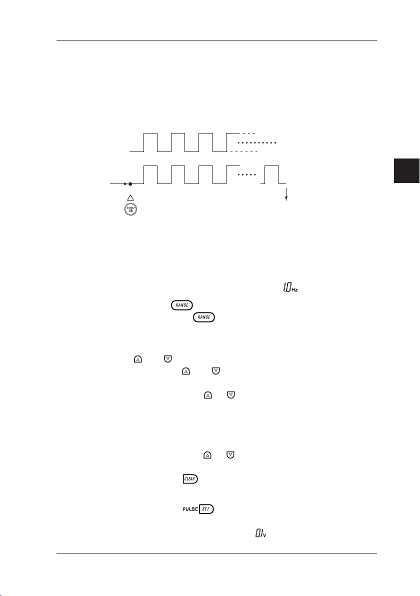
4.5 Sourcing Pulse Signals
Source of
number of pulses
n = Preset number
Amplitude setpoint
Providing Pulse Output
You can source a preset type of continuous pulse train,
a pulse signal with a preset frequency, or the preset number of
pulses.
4.5 Sourcing Pulse Signals
Frequency-based
signal
OFF ON 1 2 3 n
Press key
0V
Automatically turned off
4.5.1 Sourcing a Continuous Pulse Train
Step 1: Using the function selector switch, select
The LCD shows the default frequency
IM CA71-E
Step 2: Using the
Pressing of the
1000 Hz and 10 kHz options.
Step 3: Set the output value digit by digit using each pair of
and output setting keys.
Each pair of
the LCD reading.
Each press of the
the digit.
Increasing the digit from 9 or decreasing it from 0 causes
the digit to overow or underow, allowing you to set
the output value without interruption.
Holding down the
the digit in question.
Pressing the
the default value (differs depending on the frequency range).
Step 4: Pressing the
mode.
The LCD provides a reading of
key, set the frequency range.
key cycles through the 500.0 Hz,
and keys corresponds to each digit of
or key increases or decreases
or key continuously changes
key initializes the output setpoint to
key once switches to amplitude setting
.
Continued
of pulses
PULSE
.
4
Source
.
4-13
Page 46
4.5 Sourcing Pulse Signals
Step 5: Set the output value digit by digit using each pair of
and output setting keys.
Each pair of
the LCD reading.
Each press of the
the digit.
Increasing the digit from 9 or decreasing it from 0 causes
the digit to overow or underow, allowing you to set
the output value without interruption.
Holding down the
the digit in question.
Pressing the
the default value (0.1 V).
and keys corresponds to each digit of
or key increases or decreases
or key continuously changes
key initializes the output setpoint to
Step 6: Press the
Then, press the
key once again to show on the LCD.
key one more time to revert to
frequency setting mode.
Step 7: Pressing the
to change from
key causes the indicator on the LCD
to .
The calibrator sources a continuous pulse train with
the preset frequency and amplitude between the output
terminals.
Step 8: To turn off the output, press the
The
symbol appears on the LCD and the output terminals
key once again.
are open-circuited.
TIP
To change the frequency range, place the calibrator in frequency setting
mode with the
Then, change the frequency range using the
key.
key.
4-14
IM CA71-E
Page 47

1
2
3
4.5 Sourcing Pulse Signals
4.5.2 Sourcing the Preset Number of Pulses (Pulse Cycle)
Step 1: Using the function selector switch, select
The LCD shows the default frequency
Step 2: Using the
Each press of the
1000 Hz and 10 kHz options.
Step 3: Set the output value digit by digit using each pair of
and output setting keys.
Each pair of
the LCD reading.
Each press of the
the digit.
Increasing the digit from 9 or decreasing it from 0 causes
the digit to overow or underow, allowing you to set
the output value without interruption.
Holding down the
the digit in question.
Pressing the
the default value (differs depending on the frequency range).
Step 4: Pressing the
mode.
The LCD provides a reading of
Step 5: Set the output value digit by digit using each pair of
and output setting keys.
Each pair of
the LCD reading.
Each press of the
the digit.
Increasing the digit from 9 or decreasing it from 0 causes
the digit to overow or underow, allowing you to set
Holding down the
Pressing the
the output value without interruption.
the digit in question.
the default value (0.1 V).
key, set the frequency range.
key cycles through the 500.0 Hz,
and keys corresponds to each digit of
or key increases or decreases
or key continuously changes
key initializes the output setpoint to
key once switches to amplitude setting
and keys corresponds to each digit of
or key increases or decreases
or key continuously changes
key initializes the output setpoint to
PULSE
.
.
4
Source
.
IM CA71-E
4-15
Page 48

4.5 Sourcing Pulse Signals
Step 6: Press the
Then, press the
key once again to show on the LCD.
key.
The source setpoint reading of the LCD changes to a numeric
value, which represents the number of pulses.
Step 7: Set the number of pulses value digit by digit using each pair
of
and output setting keys.
Each press of the
or key increases or decreases
the digit.
Increasing the digit from 9 or decreasing it from 0 causes
the digit to overow or underow, allowing you to set
the output value without interruption.
Holding down the
or key continuously changes
the digit in question.
Pressing the
the default (
key initializes the output setpoint to
), thus reverting to the mode of sourcing
continuous pulse trains.
Step 8: Pressing the
key causes the indicator on
the LCD to change from to .
The calibrator sources the preset number of pulses with
the preset frequency and amplitude between the output
terminals.
Step 9: When source is complete, the calibrator automatically
turns off the output and ceases operation.
The
appears on the LCD and the output terminals are
open-circuited.
TIP
To stop sourcing pulses halfway, press the key when pulse output is
in progress.
The
appears on the LCD and the output terminals are open-circuited.
4-16
IM CA71-E
Page 49

1
2
3
4.5.3 Using the Contact Output
You can turn on or off the output terminals.
This setting is possible for both the mode of sourcing a continuous
pulse train and the mode of sourcing a given number of pulses.
An FET is used as the contact switching device.
Since the way of using the contact output is the same for both
the source of continuous pulse trains and the source of
a number of pulses, this subsection only refers to the procedure for
continuous pulse trains.
Step 1: Using the function selector switch, select
The LCD shows the default frequency
4.5 Sourcing Pulse Signals
PULSE
.
.
4
Source
Step 2: Using the
Each press of the
1000 Hz and 10 kHz options.
Step 3: Set the output value digit by digit using each pair of
and output setting keys.
Each pair of
the LCD reading.
Each press of the
digit.
Increasing the digit from 9 or decreasing it from 0 causes
the digit to overow or underow, allowing you to set
the output value without interruption.
Holding down the
the digit in question.
Pressing the
the default value (differs depending on the frequency range).
Step 4: Pressing the
mode.
The LCD provides a reading of
Step 5: Changing the reading of to with the key causes
Step 6: Press the
Then, press the
the calibrator to enter contact output mode.
frequency setting mode.
key, set the frequency range.
key cycles through the 500.0 Hz,
and keys corresponds to each digit of
or key increases or decreases the
or key continuously changes
key initializes the output setpoint to
key once switches to amplitude setting
.
key once again to show on the LCD.
key one more time to revert to
IM CA71-E
4-17
Page 50

4.5 Sourcing Pulse Signals
Step 7: Pressing the
key causes the indicator on
the LCD to change from to .
The output terminals turn on and off at the preset frequency.
Step 8: To turn off the output, press the
The
appears on the LCD and the output terminals are
key once again.
open-circuited.
NOTE
• The contact has polarities. Always connect the positive side to the H
output terminal of the calibrator and the negative side to the L output
terminal.
• Exercise the utmost care not to allow the contact current to exceed 50 mA.
4-18
IM CA71-E
Page 51

1
2
3
Keys and labels related to divided output function (n/m)
4.6 Divided Output Function (n/m)
4.6 Divided Output Function (n/m)
The divided output function (n/m) outputs a value n/m times
the setpoint of a voltage, current, resistance, thermocouple or
RTD signal.
Thus, the output value is dened as:
Output value = Main setpoint × (n/m)
n m
For details on how to set the sourced signal level of each range,
see Sections 4.2, “Sourcing DC Voltage, DC Current or SINK
Current Signal, to 4.4, “Sourcing Thermocouple (TC) Signal.”
Follow the steps shown below with the calibrator output turned off.
4
Source
Step 1: When the setting of the sourced signal level of each range is
complete, follow step 2 and later steps.
Step 2: Using each pair of
Step 3: Press the
The LCD shows
represents the value of n and the lower-order two digits
the value of m.
Step 4: Using a pair of
The variable m can be set to a value from 1 to 19.
Step 5: Using a pair of
An output value n/m times the main setpoint can be obtained
according to the setpoint of n.
The variable n can be set to a value from 0 to m.
key to enter the divided output (n/m) mode.
IM CA71-E
or keys, set the main setpoint.
. The higher-order two digits
or keys, set the value of m.
or keys, change the value of n.
4-19
Page 52

4.7 Sweep Function
Step 6: Pressing the
the LCD to change from
The calibrator sources a (main setpoint) × (n/m) signal
between the output terminals for each range selected.
Step 7: To turn off the output, press the
The
open-circuited.
Step 8: Pressing the
output (n/m) mode.
TIP
To change the main setpoint, temporarily cancel the divided output
(n/m) mode.
Set the main setpoint once again.
Then, place the calibrator in the divided output (n/m) mode once again.
appears on the LCD and the output terminals are
key causes the indicator on
to .
key once again.
key one more time cancels the divided
4.7 Sweep Function
The sweep function varies the output in a linear manner.
For further details, see Section 7.1, “Sweep Function.”
4.8 Auto Step Function
The auto step function varies the output in a step-by-step manner.
For further details, see Section 7.2, “Auto Step Function.”
4-20
IM CA71-E
Page 53
1
2
3
4.9 Temperature Monitor Function
4.9 Temperature Monitor Function
Using the key, you can show the monitored temperature on
the LCD, as described below.
■ When the Voltage, Current, Resistance or Pulse
(Continuous Pulse Train or Number of Pulses) Range Is Selected
The reading of a sourced signal remains changed to the temperature
detected by the built-in temperature sensor of the calibrator as long
as the
Thus, you can monitor the room’s temperature.
■ When the Temperature (Thermocouple or RTD) Range Is Selected
key is kept held down.
4
Source
• Pressing the
force (mV) or resistance (Ω) equivalent to the preset temperature.
The monitored value does not reect the correction made by
the RJ sensor.
• Pressing the
detected by the RJ sensor connected to the calibrator or
the internal temperature of the calibrator.
• Pressing the
setting mode.
TIP
• In approximately 10 seconds, the temperature monitor function
automatically returns to the initial normal setting mode.
• The reading of internal temperature may become higher than the room’s
temperature because of a temperature rise within the calibrator.
With an external RJ sensor, it is possible to measure the room’s temperature
more precisely.
• For a reading of monitored temperature, the unit symbol (mV, Ω or °C) blinks.
Thus, you can discriminate between a setpoint and a monitored value.
key once allows you to monitor the electromotive
key once again changes to the temperature
key one more time reverts to the initial normal
IM CA71-E
4-21
Page 54

1
2
3
4
5. Measurement
WARNING
● In an application where the calibrator is used together with the supplied
lead cables for measurement, the maximum allowable voltage from
the input terminals to ground is 300 V.
To avoid electrical shock, do NOT use the calibrator at any voltage
exceeding this maximum.
The maximum allowable terminal voltage is 300 V AC max.
● The allowable voltage to ground when the supplied terminal adapter is
attached to the input terminals is 30 Vpeak maximum.
To avoid electrical shock, do not use the terminal adapter for measuring
any circuit voltage exceeding the maximum voltage to ground.
TIP
• With the key, you can hold the measured value.
• When no measurement needs to be made, turn off the MEASURE mode
by pressing the
The measured value shown on the LCD disappears and power to
the internal measuring circuit is cut off.
This strategy saves on battery power.
• The reading of a measured value is updated at approximately one-second
intervals.
If the input is overranged, the measured value on the LCD reads as - - - - -.
key.
5
Measurement
IM CA71-E
5-1
Page 55

5.1 Connecting Cables to Terminals
5.1 Connecting Cables to Terminals
■ For DC voltage, AC voltage, resistance, frequency or pulse signal
Step 1: Connect the red lead cable for measurement (P/N: RD031)
to the H input terminal and the black lead cable to the L
input terminal.
Step 2: Connect the two clips of the cables to the measuring
terminals of equipment under test while making sure
the polarities are correct.
■ For DC current signal
Step 1: Connect the red lead cable for measurement (P/N: RD031)
to the mA input terminal and the black lead cable to the L
input terminal.
Step 2: Connect the two clips of the cables to the measuring
terminals of equipment under test while making sure
the polarities are correct.
■ For thermocouple signal (CA71 only)
Step 1: Connect the terminal adapter (P/N: 99021) to the input
terminals. This will help you connect the cables easily.
5-2
Step 2: Connect between TC RTD terminals.
The positive output leadwire of the thermocouple to the H
terminal of the terminal adapter and the negative output
leadwire to the L terminal.
■ For RTD signal (CA71 only)
Step 1: When using the terminal adapter (P/N: 99021), connect
the H, L and L terminals of the terminal adapter to the H, L
and mA terminals of the three-wire input terminal block of
the calibrator, respectively.
Step 2: Connect the A, B and B output leadwires of the RTD to
the H, L and L terminals of the terminal adapter, respectively.
IM CA71-E
Page 56

1
2
3
4
5.1 Connecting Cables to Terminals
CAUTION
• Before connecting the calibrator to the device under test, cut off the power
to the device.
• Do not apply any voltage or current exceeding the allowable voltage (300 V)
or current (120 mA).
Otherwise, there will be a danger of not only damage to the instrument
but also personal injury due to electrical shock.
• Mistaking the H voltage input terminal for the mA current input terminal,
and vice versa, when wiring is extremely dangerous.
NEVER make this mistake.
• The current input terminals are equipped with a built-in current input
protection fuse.
Overcurrent input to the terminals will cause the fuse to blow.
If the fuse is blown, replace it with one (P/N: A1635EF) with the specied
ratings.
For details on fuse replacement, see subsection 5.2.3, "Measuring DC Current."
• When using the terminal adapter (model: 99021), tighten the knob by hand.
Do not use a tool or the like.
Tightening the knob using a tool or the like may damage the terminal,
resulting in the disability of measurement.
Before storing the instrument in the carrying case, remove the terminal
adapter (model: 99021).
If the instrument is stored in the carrying case while the adapter is attached,
an external force may be applied to the terminal, thus causing damage to
the terminal and resulting in the disability of measurement.
5
Measurement
IM CA71-E
5-3
Page 57

The allowable voltage to ground
when the included terminal adapter is
attached to the input terminals is
30 Vpeak maximum.
5.2 Measuring 300 V AC-range Voltage, DC Voltage, AC Voltage or DC Current
Terminal adapter
WARNING
(99021)
Black
Red
Lead cables for measurement
(RD031)
Red
Black
5.2 Measuring 300 V AC-range Voltage,
DC Voltage, AC Voltage or DC Current
5.2.1 Measuring 300 V AC-range Voltage
CAUTION
If you make a mistake in wiring or in the operating procedure in
this measurement task, there will be a danger of not only damage to
the instrument but also personal injury due to electrical shock.
Exercise the utmost care when carrying out the measurement task.
Step 1: Make sure the lead cables for measurement are not
Step 2: Using the function selector switch, select
Step 3: Connect the lead cables for measurement to the measuring
5-4
connected to the measuring instrument under test.
300V
terminals of the measuring instrument under test.
.
IM CA71-E
Page 58

1
2
3
4
5.2 Measuring 300 V AC-range Voltage, DC Voltage, AC Voltage or DC Current
5.2.2 Measuring DC or AC Voltage
Step 1: Using the function selector switch, select the measurement
function you want to use from
.
, , and
Step 2: Using the
The DC
key, select either DC or AC.
or AC symbol appears on the LCD.
5.2.3 Measuring DC Current
Step 1: Using the function selector switch, select
Step 2: Using the
The decimal point of the measured value shown on
the LCD is repositioned.
■ Replacing the Fuse
The current input protection fuse in the mA/3WIRE terminal is
housed inside the fuse holder (labeled FUSE) on one side panel
of the calibrator.
To replace the fuse, rst remove the fuse holder labeled FUSE by
turning the holder counterclockwise with a atblade screwdriver.
Then, replace the fuse and insert the fuse holder back in place.
Fasten the fuse holder by turning it clockwise.
The replacement fuse is described below.
Part number Rating
A1635EF 100 mA/400 V
key, select either 20 mA or 100 mA.
mA
.
5
Measurement
IM CA71-E
5-5
Page 59

5.3 Measuring Resistance or RTD (CA71 only) Signal
5.3 Measuring Resistance or RTD (CA71 only)
Signal
Step 1: Using the function selector switch, select
Step 2: Using the
Pressing the key cycles through the 400 Ω,
Pt100 and JPt100 options.
TIP
• If you select the 400 Ω RTD range of the SOURCE mode at the same time,
the RTD selected on the SOURCE mode side precedes the one selected
on the MEASURE mode side.
Thus, you cannot select any RTD for the
mode. (CA71 only)
• To carry out measurement based on three-wire connection, use the 3WIRE
terminal.
key, select the range.
Ω RTD
Ω RTD
.
range of the MEASURE
5-6
IM CA71-E
Page 60

1
2
3
4
5.4 Measuring Temperature with Thermocouple (TC) - CA71 only -
5.4 Measuring Temperature with
Thermocouple (TC) - CA71 only -
NOTE
Use the terminal adapter in locations where any voltage higher than 30 V
will never be imposed on the measuring circuit.
Step 1: Using the function selector switch, select
Step 2: Using the
Pressing the key cycles through the 100 mV, K, E, J, T, R,
B, S, N, L and U options.
key, select the type of thermocouple.
100mV TC
.
5
Measurement
TIP
• If you select the 100 mV TC range of the SOURCE mode at the same
time, the thermocouple selected on the SOURCE mode side precedes
the one selected on the MEASURE mode side.
Thus, you cannot select any thermocouple for the 100 mV TC range of
the MEASURE mode.
• If there has been a sudden change in the operating ambient temperature
of the calibrator, wait until the built-in reference junction compensation
stabilizes.
Avoid using the calibrator in locations exposed to wind from such apparatus
as an air-conditioner.
• If the thermocouple has burnt out, the LCD shows the
symbol.
IM CA71-E
5-7
Page 61
5.5 Measuring Frequency or Pulses
5.5 Measuring Frequency or Pulses
5.5.1 Operating the Calibrator for Frequency Measurement
Step 1: Using the function selector switch, select
Step 2: Using the
Pressing the key cycles through the 100 Hz, 1000 Hz,
10 kHz, CPM and CPH options.
Note however that the range reading of the LCD is
given as shown below (when no signal is present).
key, select 100 Hz, 1000 Hz or 10 kHz.
LCD Reading
Range
100 Hz
1000 Hz
10 kHz
FREQ 30Vmax
.
5.5.2 Operating the Calibrator for Measuring Number of Pulses
The CPM option in this measurement counts pulses per minute,
while the CPH option counts pulses per hour.
Step 1: Using the function selector switch, select
Step 2: Using the
Pressing the key cycles through the 100 Hz, 1000 Hz,
10 kHz, CPM and CPH options.
Step 3: The
a standby-for-counting state.
The calibrator begins counting pulses the moment
the
key is pressed to cancel the hold state.
key, select either CPM or CPH.
indicator turns on and the calibrator goes into
FREQ 30Vmax
.
5-8
IM CA71-E
Page 62

1
2
3
4
5.5 Measuring Frequency or Pulses
NOTE
• If you press the key after the completion of counting while the
indicator is lit, the calibrator restarts counting from 0.
• If you press the
one hour) expires, the calibrator stops counting at that moment.
The LCD shows the number of pulses counted up to the moment.
• If the count exceeds the limit, the calibrator shows the maximum number
and stops counting.
TIP
To measure contact input, switch to that measurement function with the DIP
switch in the battery holder.
For further details, see Section 7.7, "Selecting
the Contact In Function (Contact Input for Pulse Measurement)."
key halfway before the selected time (one minute or
5
Measurement
IM CA71-E
5-9
Page 63

1
2
3
4
5
6. Memory Functions
Keys and labels related to memory function
The built-in memory has the following four functions.
With a pair of sourced and measured signal values in a set,
the calibrator can handle a maximum of 50 sets of data
(hereinafter simply referred to as data) by means of its built-in
memory.
1. Saving to Memory (MEM SAVE)
You can save data to memory.
2. Reading from Memory (MEM READ)
You can show data in memory on the LCD.
When data is being read from memory,
the source output remains turned off.
Thus, you cannot do any source task using data stored in memory.
3. Clearing Memory (MEM CLEAR)
You can clear data stored in memory.
4. Sending Data from Memory - CA71 only -
You can send data in memory to an external personal computer
using the communication function.
This function requires use of the optional RS232 communication
cable (P/N: 91017).
For further details, see Chapter 8, "Communication Function."
Memory Functions
6
MEM No.
READ
MEM
CLEAR
IM CA71-E
SAVEMEM NO.
READ
6-1
Page 64

6.1 Saving Data into Memory
6.1 Saving Data into Memory
6.1.1 Saving Data in the Order of Memory Numbers
Step 1: Press the
The MEM No. indicator on the LCD turns on.
At this point, the indicator shows a memory number
immediately following the one most recently used to
save data.
Step 2: Pressing the
(currently on-display) signal values at that moment into
the area with that memory number (address).
Executing the MEM SAVE function cancels the state of
selecting memory, reverting to normal setting mode.
Step 3: To save the next data item into the area with the next
memory number, press the
Now the MEM No. indicator shows a memory number one
count larger than the previous one.
Step 4: Pressing the
(currently on-display) signal values at that moment into
the area with that memory number (address) – the previous
memory number (address) + 1.
TIP
To cancel the memory mode (saving/reading),
press the
(Executing the MEM SAVE function automatically cancels the memory mode.)
key one more time.
key.
key saves the sourced and measured
key once again.
key saves the sourced and measured
6-2
IM CA71-E
Page 65

1
2
3
4
5
6.1 Saving Data into Memory
ndicates the memory number with which data is already saved.
(Case I)
Indication of the selection
Indication of the selection
Indication of the selection
(Case II)
Working with the MEM SAVE Function
All these are not yet used.
01 02 03 04 05 06 07 08 09 10 11 12 13 14 15 16 49 50
MEM No.07 Indication when selected
All these are not yet used. These are not yet used.
01 02 03 04 05 06 07 08 09 10 11 12 13 14 15 16 49 50
Memory Functions
Example of Key Operation
Press the key.
Press the key.
Press the key once again.
Press the key six times.
Press the key.
MEM No.14
Data is saved into the area with memory number
14 and the memory mode is cancelled.
MEM No.15
MEM No.21
Data is saved into the area with memory number
21 and the memory mode is cancelled.
NOTE
• In memory mode, some of the and keys change to those for working
with memory. Consequently, you cannot do the regular task of setting
output values for source.
• The
MEM No.
indicator begins with if no data has been saved into
memory.
If memory contains any saved data already, a memory number immediately
following the largest of the already used memory numbers is allocated to
the next data, as shown in the gure discussed above, even if there is any
not-yet-used memory address at some midpoint.
• In the case of the divided output function (n/m), the output value
"setpoint × n/m" for source is stored in memory.
6
IM CA71-E
6-3
Page 66

Alarm indication for memory overwriting
6.1 Saving Data into Memory
6.1.2 Saving Data by Selecting Desired Memory Number
Step 1: Press the
The MEM No. indicator on the LCD turns on.
Step 2: Using the pair of
number (address).
Step 3: Pressing the
(currently on-display) signal values at that moment into
the area with the selected memory number (address).
TIP
To cancel the memory mode (saving/reading),
press the
(Executing the MEM SAVE function automatically cancels the memory mode.)
key one more time.
key.
key, select the desired memory
key saves the sourced and measured
6.1.3 Overwriting Data in Memory
Step 1: Press the
Step 2: Using the pair of
number (address).
Step 3: Press the
Step 4: Pressing the
that memory number.
key.
key, select the desired memory
key. The LCD shows to alert you.
key once again overwrites the data in
6-4
IM CA71-E
Page 67

1
2
3
4
5
6.1 Saving Data into Memory
NOTE
To stop overwriting the data, press the key one time.
This cancels saving data, reverting to the original state of being able to
save/read data to/from memory.
TIP
To cancel the memory mode (saving/reading),
press the
(Executing the MEM SAVE function automatically cancels the memory mode.)
key one more time.
6.2 Reading Data from Memory
Step 1: Press the
The LCD shows MEM No. xx.
At this point, the MEM No. indicator shows a memory number
immediately following the one most recently used to save
data. (Memory is ready for data saving.)
key once.
Memory Functions
6
Step 2: Pressing the
indication to blink, indicating the calibrator is reading from
memory.
Step 3: Using the pair of
whose data you want to read.
The LCD shows the data thus read out of memory.
The items of the read data are shown on their respective
If the area with the memory number contains no saved data,
measured-value and generated-value display areas.
the LCD shows - - - - -.
key causes the on-screen READ
key, select the memory number
TIP
• To cancel reading from the memory mode,
press the
• To save data anew while reading from memory, overwrite the existing
data by following step 2 in subsection 6.1.3, "Overwriting Data in Memory."
key or the key one more time.
IM CA71-E
6-5
Page 68

6.3 Clearing Data in Memory
6.3 Clearing Data in Memory
6.3.1 Clearing Data by Selecting Desired Memory Number
Step 1: Press the
The MEM No. indicator on the LCD turns on.
Step 2: Using the pair of
whose data you want to clear.
Step 3: Pressing the
indication
(no.88 indicates object MEM No. )
Step 4: Pressing the
the selected memory number.
TIP
• To cancel clearing the data after the alarm indication is given,
press the
The calibrator reverts to memory mode (saving/reading).
• You can also clear the data after having read it from memory.
key.
key once.
key, select the memory number
key causes the LCD to show the alarm
key once again clears the data with
6-6
IM CA71-E
Page 69

1
2
3
4
5
ALL CLEAr alarm indication
6.3 Clearing Data in Memory
6.3.2 Clearing All In-Memory Data Globally
Step 1: Press the
The MEM No. indicator on the LCD turns on.
Step 2: Hold down the
The LCD shows the
Step 3: Pressing the
memory.
TIP
To cancel clearing the data after the alarm indication is given,
press the
The calibrator reverts to memory mode (saving/reading).
key.
key once.
key for at least ve seconds.
alarm indication.
key once again clears all of the data in
Memory Functions
6
6.4 Sending Out Data from Memory
- CA71 only -
See Chapter 8, "Communication Function."
IM CA71-E
6-7
Page 70

1
2
3
4
5
6
7. Functions Provided by DIP Switch
DIP switch
By conguring the DIP switch, you can use the functions listed below.
The DIP switch can be found by removing the battery holder cover at
the back of the calibrator.
CAUTION
Turn off the calibrator before you change the DIP switch conguration.
Functions Provided by DIP Switch
DIP Swich
Position
1
Sweep Selects the sweep or auto-step function.
2
Speed
3
INT RJ
4
IPTS-68
5
No use Denotes the position is not used.
6
Temp OFF
7
Contact In
8
No use Denotes the position is not used.
Changes the speed setpoint of the sweep or
auto-step function.
Selects the internal reference junction
compensation for TC signal generation.
Selects the IPTS-68 temperature scale for
temperature signal generation or measurement.
Selects contact input based operation for pulse
measurement.
Description
Factory Setting
OFF
(left-side)ON(right-side)
7
ON
12345678
IM CA71-E
7-1
Page 71

7.1 Sweep Function
The SOURCE ON
The SOURCE OFF
OFF
Sweep Mode Operation
7.1 Sweep Function
The sweep function lets you linearly change the calibrator output as
shown in the following gure.
Setpoint
Sourced-value
reading
OFF
SOURCE ON
key operation
SOURCE ON
key operation
Press
(ON)
OFF
Press
(ON)
Step 1: Press the
indication blinks.
Actual output
0
Press Press
key to turn off the calibrator.
indication blinks.
Press
When the SOURCE ON key is
pressed at midpoints during a
change in the output.
Step 2: Place switch 1 (Sweep switch) in the ON (right-side)
position.
Step 3: By setting the position of switch 2 (Speed switch),
OFF (left-side): 16 sec; ON (right-side): 32 sec
Step 4: Press the
The LCD shows SWEEP .
Step 5: Using the function selector switch, select the function
7-2
change the sweep speed.
key to turn on the calibrator.
(voltage, current, resistance, thermocouple, or RTD) for
which you want to source a signal. In the case of pulse
source, the sweep function is disabled.
IM CA71-E
Page 72

1
2
3
4
5
6
7.1 Sweep Function
Step 6: Using the pair of
the signal to be output.
The lower limit is set to a value predetermined depending on
the selected range.
Step 7: Pressing the
begins to increase.
• The LCD shows and the lower limit (default)
for approximately two seconds.
The calibrator outputs the default.
• Then, the LCD reading and the output value begin to
increase in xed increments, up to the upper limit,
in the sweep time set in the preceding steps.
• When the output reaches the setpoint, the calibrator retains
the output as is, and automatically holds sweep operation.
Step 8: Pressing the
begin decreasing. The output value decreases down to
the lower limit in the same amount of time it took to increase
up to the upper limit. When the output reaches the lower limit,
the calibrator retains the output as is for approximately three
seconds, and then automatically turns it off.
Thus, one cycle of sweeping is completed.
Step 9: To quit the sweep function, turn off the calibrator by pressing
the
key.
Step 10: Place switch 1 back in the OFF (left-side) position to disable
the sweep function.
and keys, set the upper limit of
Functions Provided by DIP Switch
key initiates sweeping and the output value
key once again causes the output value to
7
NOTE
• When the output reaches the lower limit, the calibrator retains the output
as is for three seconds, and then turns it off. Thus, one cycle of sweeping
is completed.
• To alter the direction in which the output changes, press the
sweeping is in progress (LCD reading is changing).
The calibrator alters the direction of change and continues sweep operation.
For example, pressing the
the output to begin decreasing.
key during an increase in the output causes
key when
IM CA71-E
7-3
Page 73

Sourced-value reading
SOURCE ON
key operation
0
Auto Step Operation (when the default of n is set to 1)
7.2 Auto Step Function
7.2 Auto Step Function
The auto step function automatically changes the variable n of
the n/m output in a step-by-step manner, as shown in the following
gure, when the divided output function (n/m) is selected.
Setpoint
n
1
OFF
Press
(ON)
Step 1: Press the
3 3
2 2
Stepping time setpoint
key to turn off the calibrator.
m
Actual output
2
1
Step 2: Place switch 1 (Sweep switch) in the ON (right-side)
position.
Step 3: By setting the position of switch 2 (Speed switch),
set the time of one step.
OFF (left-side): 2.5 sec/step; ON (right-side): 5 sec/step
Step 4: Press the
key to turn on the calibrator.
Step 5: Using the function selector switch, select the function
(voltage, current, resistance, thermocouple, or RTD) for
which you want to source a signal.
In the case of pulse source, the auto step function is disabled.
Step 6: Set the output value.
Step 7: Press the
key.
The SWEEP indication on the LCD changes to AUTO STEP
and the n/m symbol turns on.
7-4
IM CA71-E
Page 74

1
2
3
4
5
6
7.2 Auto Step Function
Step 8: Using each pair of
the denominator m and the starting setpoint of
the enumerator n.
(See Section 4.6, "Divided Output Function (n/m),
for further details.)
The starting setpoint is the minimum of the variable n for
auto step operation.
Step 9: Pressing the
the divided output (n/m), as described below.
Assuming the starting value of the variable n is 1,
the output cyclically changes with the variable n as n changes
in the following manner.
n = 1 → 2 → 3 → · · · (m – 1) → m → (m – 1) → · · · →
2 → 1 → 2 → 3 → · · ·
Step 10: To quit the auto step function, turn off the calibrator by
pressing the
Place switch 1 back in the OFF (left-side) position.
Note that disabling the divided output mode (n/m) before
placing switch 1 back in the OFF position enters sweep mode.
TIP
• Pressing the key to change to the SOURCE OFF state pauses
the auto step operation.
• To execute the auto step function again, press the
The auto step operation resumes from the value of n shown on the LCD.
and keys, set the value of
Functions Provided by DIP Switch
key initiates the automatic stepping of
key.
7
key.
IM CA71-E
7-5
Page 75

7.3 Selecting the INT RJ Function
7.3 Selecting the INT RJ Function
The INT RJ function compensates for the measured reference
junction temperature by using the calibrator's built-in RJ sensor.
The function enables you to generate thermoelectromotive force
that is based on the measured temperature from the calibrator's
output terminal. The built-in temperature sensor is located near
the calibrator's terminals. Because the thermoelectromotive force
generated using this method does not match that generated using
an external RJ sensor,* the accuracy of this measurement is not
guaranteed. For more accurate reference junction compensation,
be sure to use the optional RJ sensor (P/N: B9108WA).
* The terminal temperature of the thermometer under verication
is measured using an external RJ sensor, and this temperature
is used as the reference junction temperature.
Step 1: Press the
Step 2: Place switch 3 (INT RJ switch) in the ON (right-side) position.
The calibrator detects temperature using its built-in
temperature sensor and outputs reference junction-
compensated thermoelectromotive force appropriate for
the detected temperature.
Step 3: To disable the INT RJ function, turn off the calibrator by
pressing the
Step 4: Place switch 3 back in the OFF (left-side) position.
TIP
Even when the INT RJ function is selected, the temperature detected by
an external RJ sensor precedes any other measured temperature
if you plug the sensor into the RJ INPUT connector.
For further details, see Appendix 1, " Reference Junction
Compensation."
key to turn off the calibrator.
key.
7-6
IM CA71-E
Page 76

1
2
3
4
5
6
7.4 Selecting the IPTS-68 Function
7.4 Selecting the IPTS-68 Function
By placing switch 4 (IPTS-68 switch) in the ON (right-side) position,
you can select the IPTS-68 temperature scale when you choose
the type-K, E, J, T, N, R, S or B thermocouple or the Pt100 RTD.
Placing the switch in the OFF position results in the selection of
the ITS-90 temperature scale.
TIP
When you have selected a type of thermocouple or RTD,
the LCD shows IPTS-68.
7.5 Switch Not Used
Although switch 5 (No Use switch) of the DIP has no effect on
calibrator operation, the switch should be placed in the OFF
(left-side) position.
Functions Provided by DIP Switch
7
7.6 Temp Switch
Check that the switch should be placed in the OFF position.
7.7 Selecting the Contact In Function (Contact Input for Pulse Measurement)
By placing switch 7 (Contact In switch) in the ON (right-side) position,
you can measure transistor contact on-off signals.
If you select the contact input function, the
appears on the LCD.
By placing the switch in the OFF position, you can measure normal
pulse.
(contact) symbol
IM CA71-E
7-7
Page 77

1
2
3
4
5
6
7
8. Communication Function - CA71 only -
You can congure the calibrator from a personal computer just as
you do with the calibrator's panel keys (except for turning on/off
the power, conguring the function selector switch, and setting
the communication function).
You can also verify the setpoint, measured value and status of
the calibrator.
NOTE
• With the optional communication cable (P/N: 91017), you can use the RS232
serial port (9-pin D-sub) of a personal computer or any other equipment.
• In talk-only or printer mode, you can output the source setpoint and
measured value at preset intervals.
Communication Function
8.1 Cables Connection and Interface
Specications
■ Connecting Communication Cable
Remove the I/O port cover at the back of the calibrator and connect
the communication cable (P/N: 91017) to the I/O port.
8
■ Setting RS232 Parameters
Baud rate: 9600 baud
Parity: None
Stop bits: 2 bits
Data length: 8 bits
Flow control: None (Xon/Xoff control for printing only)
Delimiter: Fixed to CrLf
IM CA71-E
8-1
Page 78

8.2 Setting the Mode
8.2 Setting the Mode
Step 1: Press the
the
The LCD shows
, or in its lower section.
Step 2: Using the pair of
Step 3: Press the
If you set the mode to
When the
outputs one data item.
Step 4: If you set any value using the pair of
shown, the calibrator outputs data using the value thus
set as the time interval (sec).
The value should be set within the range from 0 to 3600.
TIP
• To close the communication setting screen, press the key once again
while simultaneously holding down the
• Even if you turn off the calibrator, the communication mode and interval
you have set are saved internally until you replace the batteries or
recongure the communication function.
Thus, communication will take place with the previous settings.
key while simultaneously holding down
key.
in its upper section and either
and keys, select , or .
key to conrm your mode selection.
or , the LCD shows .
is indicated, each press of the key
and keys with
key.
8.3 Types of Mode
: Normal mode – Permits normal transmission and reception.
: Talk-only mode – Outputs the source setpoint and measured
: Printer mode – Outputs the source setpoint and measured
*: For a 0-second interval, each press of the
item. For other intervals, pressing the
communication.
8-2
value at preset intervals (0* to 3600 sec).
value to a printer at preset intervals
(0* to 3600 sec).
key outputs one data
key initiates or terminates
IM CA71-E
Page 79

1
2
3
4
5
6
7
8.4 Data Format
TIP
When communication is in progress, the indicator blinks,
telling you data is being output.
Care must be taken therefore, since the hold function of the MEASURE
mode is disabled if you select
or .
8.4 Data Format
Data is output from the calibrator in the following format.
Source: Function 1V
Range DC V
Data 1.0000
Measure: Function 100 mV
Range k
Data 25.5C
8.5 Data Structure
The calibrator's program has the following data structure.
Command + Parameter + Delimiter
Command: Dened by one to three alphabetical
upper-case letters.
Parameter: A string of ASCII-code numerals or characters.
Delimiter: Fixed to CrLf.
Communication Function
8
IM CA71-E
8-3
Page 80

8.6 Commands
8.6 Commands
Command Description
BL Turns the back lighting on and off/queries the current setting.
DW Moves down the “m-th” digit of the sourced setpoint by one digit.
UP Moves up the “m-th” digit of the sourced setpoint by one digit.
H Enables/Disables the output data header/queries the current setting.
HD Enables/Disables data hold mode/queries the current setting.
MF Queries the measurement function.
MO On/Off of measurement/queries the current setting.
MR Sets the measuring range/queries the current setting.
OD Outputs measured value.
OE Outputs error information.
OR Queries whether an external RJC sensor is connected.
OS Outputs the setting information.
SD Sets sourced setpoint/queries the current setting.
SF Queries the source function.
SO On/Off of source output/queries the current setting.
SR Sets the sourcing range/queries the current setting.
SY Switches between the normal and adjustment modes/queries the
current setting.
CD Sets the sourced setpoint/queries the current setting.
CL Sets the adjustment item/queries the current setting.
CP Sets the adjustment point.
CW Saves the adjusted data.
CMF Queries the measurement function.
CSF Queries the source function.
OM Queries memory data.
NM Sets divided output (n/m) mode/queries the current setting.
ND Sets n/m values in divided output (n/m) mode/queries the current
setting.
TE Sets the temperature monitor display for sourced TC/RTD
range/queries the current setting. (TC, RTD mode only)
PU Sets the display for sourced pulse range/queries the current setting.
8-4
IM CA71-E
Page 81

1
2
3
4
5
6
7
Turns
the back lighting on and off /queries the
When normal
m=0: Hold Off m=1: Hold On
8.7 Detailed Description of Commands
8.7 Detailed Description of Commands
BL
Syntax for setting
BLm<delimiter>
Syntax for query
BL?<delimiter> ⇒ Response: BLm<delimiter>
Description of parameter
m=0: Off m=1: On
DW
Syntax for setting
DWm<delimiter>
Description of parameter
m: Specifies a digit 1 (the lowest digit) to 5 (the highest digit)
UP
Syntax for setting
UPm<delimiter>
Description of parameter
m: Specifies a digit 1 (the lowest digit) to 5 (the highest digit)
H
Syntax for setting
Hm<delimiter>
Syntax for query
H?<delimiter> ⇒ Response: Hm<delimiter>
* For details on the header, see the OD command.
Description of parameter
m: Enables/Disables the header
HD
Syntax for setting
HDm<delimiter>
Syntax for query
HD? <delimiter> ⇒ Response: HDm (delimiter)
Description of parameter
m: Specifies data hold
current setting.
Moves down the “m-th” digit of the sourced setpoint
by one digit.
Moves up the “m - th” digit of the sourced setpoint
by one digit.
Enables/Disables
current setting.
m=0: Disabled m=1: Enabled
Enables/Disables
setting.
the output data header/queries the
data hold mode/queries the current
condition
When normal
condition
When normal
condition
When normal
condition/adjustment
When normal
condition
Communication Function
8
IM CA71-E
8-5
Page 82
8.7 Detailed Description of Commands
MF Queries the measurement function.
Syntax for query
MF? <delimiter> ⇒ Response: MFm<delimiter>
Description of parameter
m: Measurement function
m=0: 300V AC m=1: 100V m=2: 10V
m=3: 1V m=4: 100mV m=5: Resistance
Syntax for setting
Syntax for query
Description of parameter
Syntax for setting
Syntax for query
Description of parameter
m=6: Frequency m=7: Current
MO On/Off of measurement/queries the current setting.
MOm<delimiter>
MO?<delimiter> ⇒ Response: MOm <delimiter>
m: On/Off condition
m=0: Off m=1: On
Sets
MR
MRm<delimiter>
MR? <delimiter> ⇒ Response: MRm<delimiter>
m: Measuring range
[100V] m=0: DC m=1: AC
[10V] m=0: DC m=1: AC
[1V] m=0: DC m=1: AC
[100mV] (When normal condition)
m=0: 100mV DC m=1: TcK m=2: TcE
m=3: TcJ m=4: TcT m=5: TcR
m=6: TcB m=7: TcS m=8: TcN
m=9: TcL m=10: TcU
[100mV] (When adjustment)
m=0: 100mV DC m=1: TcK m=2: TcE
m=4: TcT
[Ω] m=0: 400Ω m=1: Pt100 m=2: JPt
[Freq ] m=0: 100Hz m=1: 1kHz m=2: 10kHz
[mA]
the measuring range/queries the current
setting.
m=0: 20mA m=1: 100mA
When normal
condition
When normal
condition/adjustment
When normal
condition/adjustment
8-6
IM CA71-E
Page 83
1
2
3
4
5
6
7
8.7 Detailed Description of Commands
OD Outputs measured value.
Syntax for setting
OD<delimiter> ⇒ Response: ODabcde<delimiter>
Description of parameter
<Header section> (Output only when the header is set to “enabled”.)
a= V: Voltage A: Current O: Resistance T: Temperature F: Frequency
b= DC: Direct current AC: Alternating current
c= N: Normal O: Overrange E: No data
<Data section>
d = Measured value, mantissa part (7 digits)
e = Measured value exponent part (E- 3 / E+0 / E+3)
de = 99999. E+3 when overrange occurs or no data reside.
OE Outputs error information.
Syntax for setting
OE<delimiter> ⇒ Response: ERRm<delimiter>
Description of parameter
m: Error information
m=00: No error
m=11: Received command not used in this instrument
m=12: Specified parameter value is outside allowed range.
m=13: Attempt made to execute a command that is not permitted in
a certain status of the instrument.
m=16: An error was received during adjustment.
OR
Syntax for query
OR<delimiter> ⇒ Response: m
Description of parameter
m: Connecting condition of external RJC
OS Outputs the setting information.
Syntax for setting
OS<delimiter>
Response
Measure m<CrLf> m= On/Off
Function m<CrLf> m= Measurement function
Range m<CrLf> m= Measuring range
Source m<CrLf> m= On/Off
Function m<CrLf> m= Source function
Range m<CrLf> m= Source range
Data m<CrLf> m= Sourced setpoint
Light m<CrLf> m= On/Off
Queries
whether an external RJC sensor is
connected.
m=0: Not connected m=1: Connected
When normal
condition/adjustment
When normal
condition/adjustment
When normal
condition
When normal
condition
Communication Function
8
IM CA71-E
8-7
Page 84

8.7 Detailed Description of Commands
SD Sets sourced setpoint/queries the current setting.
Syntax for setting
SDm<delimiter>
Syntax for query
SD?<delimiter> ⇒ Response: SDm<delimiter>
Description of parameter
m: Sourced setpoint (7 digits) ex. +1.0000
SF Queries the source function.
Syntax for query
SF? <delimiter> ⇒ Response: SFm<delimiter>
Description of parameter
m: Function
m=0: 30V m=1: 10V m=2: 1V m=3: 100mV
m=4: Resistance m=5: Pulse m=6: 20mA m=7: 4 to 20mA
Syntax for setting
Syntax for query
Description of parameter
Syntax for setting
Syntax for query
Description of parameter
m=8: 20mASINK
SO On/Off of source output/queries the current setting.
SOm<delimiter>
SO? <delimiter>
m: Condition of generation (source)
m=0: Off m=1: On
Sets
SR
SRm<delimiter>
SR?<delimiter> ⇒ Response: SRm<delimiter>
m: sourcing range
setting.
[100mV] (When normal condition)
m=0: DC 100mV m=1: TcK m=2: TcE
m=3: TcJ m=4: TcT m=5: TcR
m=6: TcB m=7: TcS m=8: TcN
m=9: TcL m=10: TcU
[100mV] (When adjustment)
m=0: DC 100m V m=1: TcK
[Ω] m=0: 400Ω m=1: Pt100 m=2: JPt
[Freq ] m=0: 500Hz m=1: 1kHz m=2: 10kHz
Response: SOm<delimiter>
⇒
the sourcing range/queries the current
When normal
condition
When normal
condition
When normal
condition/adjustment
When normal
condition/adjustment
8-8
IM CA71-E
Page 85
1
2
3
4
5
6
7
8.7 Detailed Description of Commands
Switches
SY
Syntax for setting
SYm<delimiter>
Syntax for query
SY?<delimiter> ⇒ Response: SYm<delimiter>
Description of parameter
m: Mode
CD
Syntax for setting
CDm<delimiter>
Syntax for query
CD? <delimiter> ⇒ Response: CDm<delimiter>
Description of parameter
CL
Syntax for setting
CLm<delimiter>
Syntax for query
CL?<delimiter> ⇒ Response: CLm<delimiter>
Description of parameter
m: Adjustment item
CP Sets the adjustment point. When adjustment
Syntax for setting
CPm<delimiter>
Description of parameter
m: Adjustment point
CW Saves the adjusted data. When adjustment
Syntax for setting
CW<delimiter>
modes/queries the current setting.
m=0: Normal mode m=1: Adjustment mode
Sets
setting.
m: Sourced setpoint (8 digits) ex. +1.00003
Sets
setting.
m=3: Adjustment of source m=4: Adjustment of measurement
m=0: FS adjustment m=1: Zero adjustment
Be sure to execute CW command after adjustment for each function/range.
Without executing CW command, the adjusted value will be deleted when the
power is turned off.
between the normal and adjustment
the sourced setpoint/queries the current
the adjustment item/queries the current
When normal
condition/adjustment
When adjustment
When adjustment
Communication Function
8
IM CA71-E
8-9
Page 86

8.7 Detailed Description of Commands
CMF Queries the measurement function. When adjustment
Syntax for query
CMF?<delimiter> ⇒ Response: CMFm<delimiter>
Description of parameter
m: Measurement function
m=0: AC 300V m=1: 100V m=2: 10V
m=3: 1V m=4: 100mV m=5: Resistance
Syntax for query
Description of parameter
Syntax for query
Response:
Description of parameter
m=6: Frequency m=7: Current
CSF Queries the source function. When adjustment
CSF?<delimiter> ⇒ Response: CSFm<delimiter>
m= Function
m=0: 30V m=1: 10V m=2: 1V m=3: 100mV
m=4: Resistance m=5: Pulse m=6: 20mA m=7: 4 to 20mA
m=8: 20mASINK
OM Queries memory data.
OMm<delimiter>
abcde, fghij [, fghij ] <delimiter>
<Header section of measured value>
a= V: Voltage A: Current O: Resistance T: Tem perature F: Frequency
b= DC: Direct current AC: Alternating current
c= N: Normal O: Overrange E: No data
<Data section of measured value>
d = Measured value, mantissa part (7 digits)
e = Measured value exponent part (E- 3 / E+0 / E+3)
<Header section of sourced setpoint>
f= V: Voltage A: Current O: Resistance T: Temperature F: Frequency
g= DC: Direct current AC: Alternating current
h= N: Normal E: No data
i = Sourced setpoint, mantissa part (7 digits)
j = Sourced setpoint exponent part (E - 3 / E+0 / E+3)
m: Number of memory 1 to 50
When normal
condition
8-10
IM CA71-E
Page 87

1
2
3
4
5
6
7
m=2: Pulse number
8.7 Detailed Description of Commands
NM
Syntax for setting
MNm<delimiter>
Syntax for query
MN?<delimiter> ⇒ Response: MNm<delimiter>
Description of parameter
m: n/m mode
ND
Syntax for setting
NDnm<delimiter>
Syntax for query
ND?<delimiter> ⇒ Response: NDnm<delimiter>
Description of parameter
n: n-value (2 digits among numbers from 00 to 19, where n ≤ m)
m: m-value (2 digits among numbers from 01 to 19, where n ≤ m)
TE
Syntax for setting
TEm<delimiter>
Syntax for query
TE?<delimiter> ⇒ Response: TEm<delimiter>
Description of parameter
m: Condition of display
PU
Syntax for setting
PUm<delimiter>
Syntax for query
PU?<delimiter> ⇒ Response: PUm<delimiter>
Description of parameter
m: Condition of display
Sets divided output (n/m) mode/queries the current
setting.
m=0: Off m=1: On
Sets
n/m values in divided output (n/m) mode/
queries the current setting.
Sets the temperature monitor display for sourced
TC/RTD range/queries the current setting.
(TC, RTD mode only)
m=0: Value of temperature
m=1: Value of equivalent voltage (resistance)
m=2: Reference junction temperature
Sets the display for source pulse range/queries
the current setting.
m=0: Frequency
m=1: Amplitude
When normal
condition
When normal
condition
When normal
condition
When normal
condition
Communication Function
8
IM CA71-E
8-11
Page 88

1
2
3
4
5
6
7
8
9. Troubleshooting and Calibration
■ Troubleshooting
Failure Checklist
Troubleshoot the cause of any problem using the following checklist.
Should the problem persist even if you have taken the given
corrective action or if you notice any problem not listed herein,
contact the vender from which you purchased the instrument.
Problem Corrective Action
The LCD shows nothing even
if the POWER switch is
turned on.
The LCD shows everything
except for the measured value.
The SOURCE indicator remains
set to OFF even if the SOURCE
ON key is operated for signal
source.
The output cannot be turned on
for signal source, or no signal
is output even if the output is
turned on.
The measured and sourced
signal values are abnormal.
The calibrator cannot be
congured or controlled
via RS232 interface-based
communication.
The hold function of the
MEASURE mode does not
work at all.
The LCD shows Err60 at
power-on.
– When the calibrator is operated on batteries
• Make sure the batteries are securely housed in
the holder.
• Check if the batteries are too low.
• Check if the AC adapter plug is inserted to
the calibrator but the adapter is not connected to
the AC power source.
– When the calibrator is operated on AC adapter
• Check if the AC adapter is reliably supplied with
electricity.
• Check if the MEASURE OFF key for turning
on/off the MEASURE mode is set to OFF.
• When in voltage signal source, check if the load
current is beyond the specied limits.
• When in current signal source, check if the load
resistance is too large.
• The built-in fuse may blow off if any abnormal
voltage level is applied to the output terminals.
If this is the case, the calibrator needs repair.
• Check if the signal carries noise.
•
When in resistance signal source, check if the input
stage of the device under test contains a capacitor
with an excessively large capacitance.
• Make sure the communication parameter
settings are correct.
• Check if the communication mode is set to
or
tonLy
• The calibrator needs repair.
Print
.
Troubleshooting and Calibration
9
IM CA71-E
9-1
Page 89

9. Troubleshooting and Calibration
■ Calibration
We recommend that you calibrate the instrument once a year to
maintain its accuracy (high accuracy).
For a service of calibration, contact the dealer from which you
purchased the instrument.
9-2
IM CA71-E
Page 90

1
2
3
4
5
6
7
8
9
10. Method of Calibrator Adjustment
We recommend that you calibrate the instrument once a year to
maintain its accuracy (high accuracy).
If the calibrator needs to be readjusted, follow the procedure
described below.
For a service of calibration or readjustment, contact the dealer from
which you purchased the instrument.
10.1 Calibration Standard Selection and
Environmental Requirements
■ Selection of Calibration Standard
Select an appropriate calibration standard having the ranges
shown in the following table and accuracy levels equal to or
higher than those shown in the table.
Method of Calibrator Adjustment
Source Functions
Function
to Be
Adjusted
DCV
DCA 20 mA 22 mA ±(0.002%+0.3 μA)
SINK 20 mA 20 mA ±(0.002%+0.3 μA)
Ω/1 mA 400 Ω 440 Ω ±(0.0025%+0.01 Ω)
Ω/5 mA 400 Ω 2.2 V/5 mA
Standard's
Name
Digital multimeter
(DMM)
Note:
Also use a 100 Ω
standard resistor
for the DCA and
SINK functions
and a high-precision
5 mA
current source
for the Ω/5 mA
function.
Range
to Be
Adjusted
100 mV
1 V
10 V
30 V
Measuring
Range
110 mV
1.1 V
11 V
33 V
Accuracy Remarks
±(0.002%+1.5 μV)
±(0.002%+10 μV)
±(0.002%+100 μV)
±(0.002%+1 mV)
±(0.0025%
±(0.0025%
)
)
---
Measure the current
with the DMM’s mA
range or measure the
voltage drop across
the 100 Ω standard
resistor with the
DMM’s voltage range.
DMM's resistance
range (1mA)
High-precision
current source
(5 mA)
DMM's voltage
range
10
IM CA71-E
10-1
Page 91

10.1 Calibration Standard Selection and Environmental Requirements
Key for
confirming/saving
adjustment value
Keys for switching
between the
measurement and
source CAL modes.
0 denotes zero-point
CAL-mode Operation keys and Display Indications
Measurement Functions
Function
to Be
Adjusted
DCV
DCA
Ω
ACV
Standard's
Name
High-precision
calibrator
Decade
resistance box
AC calibrator or
AC voltage
source
Range
to Be
Adjusted
100 mV
1 V
10 V
30 V
20 mA
100 mA
--- 400 Ω ±(0.01%) ---
1V
10 V
100 V
300 V
Measuring
Range
100 mV
1 V
10 V
30 V
20 mA
100 mA
1 V
10 V
100 V
300 V
Accuracy Remarks
±(0.0025%+1 μV)
±(0.0025%+20 μV)
±(0.0025%+0.2 mV)
±(0.005%+2 mV)
±(0.0025%+0.4 μA)
±(0.004%+3 μA)
±(0.08%+0.015%) ---
---
---
■ Environmental Requirements
Ambient temperature: 23 ±1°C
Relative humidity: 45 to 75%
Warm-up: Before use, warm up the calibration
standard for the period of time specied
for the standard.
The indicator blinks when
any source function is being operated.
Keys for adjusting the
setpoint value of source
Keys for selecting/canceling
CAL mode
(Press in combination.)
10-2
Auxiliary-digit indicator
(The value should be read as 400.000.)
CAL mode indicator
adjustment and FS
denotes full-scale
adjustment.
Keys for adjusting the two digits,
including the auxiliary digit
IM CA71-E
Page 92

1
2
3
4
5
6
7
8
9
10.2 Adjusting Source Functions
20 mA output
Hook-ups for Adjustment
10.2 Adjusting Source Functions
Table 10.1 Adjustment Points of Source Functions
Range
100 mV 0 100 mV ---
1 V 0 1 V ---
10 V 0 10 V ---
30 V 0 30 V ---
20 mA 0 20 mA See the gure below.
20 mA SINK 0.1 mA 20 mA See the gure below.
400 Ω/1 mA 0 400 Ω Four-wire connection
400 Ω/5 mA 0 400 Ω See the gure below.
*1: Adjust the source functions so that the readings of the calibration standard
(output values of the CA51/71) match the adjustment points listed above.
Adjustment Points *
CAL 0 CAL FS
1
Remarks
Method of Calibrator Adjustment
TIP
• You can also select only the range in need of readjustment to adjust
it separately.
• Always make zero-point (0) adjustments together with full-scale (FS)
adjustments.
CA71
Standard resistor
SINK
H
L
100 Ω
20 mA
SINK
20 mA and SINK ranges 400 Ω/5 mA
Voltage range
H
24V
L
DMM
Power
supply
CA71
H
L
5 mA
DMM
Voltage range
High-precision
current source
10
IM CA71-E
Step 1: Press the
the
Step 2: Pressing the
The
key while simultaneously holding down
key. The LCD shows .
key enters the source CAL mode.
indicator blinks on the LCD and the symbol
appears.
The calibrator is now ready for the zero-point adjustment of
source functions.
10-3
Page 93

10.2 Adjusting source Functions
Step 3: From Table 10.1, select the range you want to adjust.
Then, point the function selector switch to that range and
press the
Step 4: Conform that the
Step 5: Read the calibrator output on the calibration standard.
Then, using the lowest-order pair of
adjust the reading so that it matches the given CAL 0
adjustment setpoint in Table 10.1. In the CAL mode,
the lowest-order pair of
or decrease the least-signicant two digits,
including the auxiliary digit.
Adjust the value measured with the calibration standard to
the given adjustment setpoint in Table 10.1.
key.
symbol is appearing on the LCD.
and keys,
and keys are used to increase
Step 6: Press the
The CAL indicator on the LCD changes to
key to conrm the CAL 0 adjustment setpoint.
,
setting the calibrator ready for full-scale adjustment.
Step 7: Using the lowest-order pair of
and keys,
adjust the reading of the calibration standard so that it
matches the given CAL FS adjustment setpoint in Table 10.1.
Step 8: Press the
key to conrm the CAL FS adjustment setpoint.
The 0 and FS symbols on the LCD blink.
Step 9: Pressing the
once again saves the adjustment setpoint in
memory.
Step 10: The 0 and FS symbols stop blinking,
causing the calibrator to return to the state discussed in step 4.
Using the function selector switch, select the next range.
By repeating steps 4 to 9, you can adjust the source function
assigned to that range.
10-4
IM CA71-E
Page 94

1
2
3
4
5
6
7
8
9
10.2 Adjusting source Functions
NOTE
• Saving to memory results in the overwriting of existing data.
Be extremely careful since the previous adjustment setpoints are cleared.
• Both the thermocouple and RTD ranges are adjusted at the same time
when the 100 mV and 400 Ω ranges are adjusted.
TIP
With the CAL mode selected, press the key while holding down
key.
the
This key operation cancels the CAL mode (the same key operation as for
selecting the CAL mode).
You can use the same key operation to cancel the CAL mode during
adjustment, before saving to memory.
CAUTION
Method of Calibrator Adjustment
Precautions when adjusting the 400 Ω range for resistance signal source
(1) Internal Offset Adjustment
When setting a resistance of 0.00 Ω , make sure the voltage between
the H and L terminals is within ±20 µV. If the voltage is beyond the limits,
internal adjustments must be made. Contact the vender from which you
purchased the instrument.
(2) Notes on Resistance-measuring Current
Adjusting the 400 Ω range requires drawing two types of resistance-
measuring current – 1 mA and 5 mA – from an external device.
Adjust the range separately for each of these currents.
Adjustment for 1 mA
This adjustment is possible with the resistance measuring range of
the calibration standard (digital multimeter). At this point,
make sure the resistance-measuring current is 1 mA.
Adjustment for 5 mA
Like the method of adjusting the 400 Ω/5 mA range shown in the gure
(Hook-ups for Adjustment) on page 10-3, you can make this adjustment
by applying the reference current of 5 mA from the external device and
then measuring the resulting voltage drop.
10
IM CA71-E
10-5
Page 95

10.3 Adjusting Measurement Functions
10.3 Adjusting Measurement Functions
Table 10.2 Adjustment Setpoints of Measurement Functions
Range
DC 100 mV --- 100 mV ---
DC 1 V --- 1 V ---
DC 10 V --- 10 V ---
DC 100 V --- 100 V ---
DC 20 mA --- 20 mA ---
DC 100 mA --- 100 mA ---
400 Ω 0 Ω 380 Ω Three-wire connection
AC 1 V 0 V 1V/50 to 60 Hz ---
AC 10 V 0 V 10 V/50 to 60 Hz ---
AC 100 V 0 V 100 V/50 to 60 Hz ---
AC 300 V 0 V 300 V/50 to 60 Hz ---
*2: Apply the reference input signals listed above from the calibration standard.
Adjustment Points *
CAL 0 CAL FS
2
Remarks
TIP
• You can also select only the range in need of readjustment to adjust
it separately.
• Always make zero-point (0) adjustments together with full-scale (FS)
adjustments.
10.3.1 Adjusting DC Voltage and DC Current Ranges
Step 1: Press the
the
Step 2: Pressing the highest-order
Step 3: Pressing the
The
appears.
The calibrator is now ready for the dening the CAL FS
setpoint of measurement functions.
10-6
key while simultaneously holding down
key. The LCD shows .
key causes the LCD to show
.
key enters the measurement CAL mode.
indicator blinks on the LCD and the symbol
IM CA71-E
Page 96

1
2
3
4
5
6
7
8
9
CAL-mode Operation Keys and Display Indications
10.3 Adjusting Measurement Functions
Step 4: Apply the CAL FS adjustment setpoint input of each range in
Table 10.2 from the calibration standard to the H and L input
terminals of the calibrator.
Step 5: Pressing the
setpoint. At this point, the
Step 6: Pressing the
in memory.
key conrms the CAL FS adjustment
symbol blinks.
once again saves the adjustment setpoint
Method of Calibrator Adjustment
NOTE
• Range adjustments are made automatically within the calibrator so that
the LCD reading matches the adjustment setpoint in question given in
the table with reference to the input applied as described above.
Therefore, you need not make any range adjustment with
• Saving the adjustment setpoint results in the overwriting of existing data.
Be extremely careful since the previous adjustment setpoints are cleared.
and keys.
Step 7: The
TIP
Press the key while holding down the key.
This key operation cancels the CAL mode.
You can use the same key operation to cancel the CAL mode during
calibration, before saving to memory.
When adjusting DC current range, using the
change DC 20 mA → DC 100 mA.
symbol stops blinking, causing the calibrator to return
to the state discussed in step 4. Using the function selector
switch, select the next range. By repeating steps 4 to 6,
you can adjust the measurement function assigned to that
range.
key,
10
IM CA71-E
10-7
Page 97

10.3 Adjusting Measurement Functions
10.3.2 Adjusting AC Voltage and Resistance (400 Ω) Ranges
Step 1: Press the
the
Step 2: Pressing the highest-order
Step 3: Pressing the
The
appears. The calibrator is now ready for dening the CAL 0
setpoints of measurement functions.
Step 4: Using the function selector switch, select the range to be
adjusted.
Step 5: Pressing the
The CAL indicator on the LCD changes to
setting the calibrator ready for full-scale calibration.
Step 6: Apply the CAL FS adjustment setpoint input of each range in
Table 10.2 from the calibration standard to the H and L input
terminals of the calibrator.
Step 7: Pressing the
setpoint. At this point, the 0 and FS symbol blinks.
Step 8: Pressing the
in memory.
key while simultaneously holding down
key. The LCD shows .
key causes the LCD to show
.
key enters the measurement CAL mode.
indicator blinks on the LCD and the symbol
key conrms the CAL 0 adjustment setpoint.
,
key conrms the CAL FS adjustment
once again saves the adjustment setpoint
NOTE
• Range adjustments are made automatically within the calibrator so that
the LCD reading matches the adjustment setpoint in question given in
the table with reference to the input applied as described above.
Therefore, you need not make any range adjustment with
• Saving the adjustment setpoint results in the overwriting of existing data.
Be extremely careful since the previous adjustment setpoints are cleared.
• The temperature measuring ranges of the RTD function are adjusted at
the same time when the 400 Ω range is adjusted.
10-8
and keys.
IM CA71-E
Page 98
1
2
3
4
5
6
7
8
9
10.3 Adjusting Measurement Functions
Step 9: The 0 and FS symbols stop blinking, causing the calibrator
to return to the state discussed in step 4.
Using the measurement range setting rotary switch,
select the next range.
By repeating steps 4 to 8, you can adjust the measurement
function assigned to that range.
TIP
Press the key while holding down the key.
This key operation cancels the CAL mode.
You can use the same key operation to cancel the CAL mode during calibration,
before saving to memory.
10.4 Notes on the Adjustment of
Method of Calibrator Adjustment
10.5 Post-adjustment Verication
Temperature Ranges - CAL71 only -
Adjusting the temperature measuring ranges of the thermocouple
function involves using special equipment to make reference junction
compensation adjustments.
For this reason, contact the vender from which you purchased
the instrument to perform this adjustment.
10
When adjustment work is done, test the calibrator to ensure that
adjustments have been made correctly and adjustment setpoints
have been saved into memory correctly.
To do this test, turn off the calibrator once and turn it back on again.
Then, place the calibrator in normal source or measurement mode
and check the setpoints using the same calibration standard.
IM CA71-E
10-9
Page 99

1
2
3
4
5
6
7
8
9
10
11. Using Accessories
Lead cables for
(B9108WA)
(for CA71 only)
The allowable voltage to ground when
the included terminal adapter is
attached to the input terminals is
30 Vpeak maximum.
When attaching accessories to the calibrator, refer to the following
gure. When connecting the included terminal adapter, make sure
the adapter is positioned in the correct orientation.
Terminal adapter
WARNING
(99021)
Lead cables for measurement
(RD031)
Fuse
(A1635EF)
Black
Red
Black
Red
Red
Black Black
source
(98020)
Using Accessories
RJ sensor
AC adapter
11
RS232 communication
cable
(91017)
IM CA71-E
11-1
Page 100

1
2
3
4
5
6
7
8
9
10
11
12. Specications
(1) Signal sourcing unit range and accuracy (for both CA51 and CA71)
Parameter
DC
voltage
DC
current
mA SINK
Resistance
RTD
TC *
Frequency,
pulse
Temperature coefficient: Accuracy shown above × (1/5)/°C
*1: Output up to 24 V/22 mA is possible when using the AC adapter.
*2: As per JIS C 1604 (ITS-90). IPTS-68 may be selected through internal settings (DIP switch).
*3: Excitation current: If less than 0.1 mA to 0.5 mA, then add [0.025/ls (mA)] Ω or [0.06/ls (mA)]°C.
*4: As per JIS C 1602 (ITS-90) (L and U are DIN specs).
K, E, J, T, N, R, S, and B may be switched to IPTS-68 through internal settings (DIP switch)
*5: Frequency (interval between one pulse and another) and amplitude during pulse cycle source
Reference
100 mV
1 V
10 V
30 V
20 mA
4-20 mA
20 mA
400 Ω
Pt100 *
JPt100
K
E
J
T
N
L
U
4
R
S
B
500 Hz
1000 Hz
10 kHz
Pulse
cycle *
(L and U are not switched).
may have the same range as during frequency source.
Range
-10.00 –110.00 mV
0 – 1.1000 V
0 – 11.000 V
0 – 30.00 V
0 – 24.000 mA
4/8/12/16/20 mA
0.1 – 24.000 mA
0 – 400.00 Ω
2
-200.0 – 850.0°C
-200.0 – 500.0°C
-200.0 – 1372.0°C
-200.0 – 1000.0°C
-200.0 – 1200.0°C
-200.0 – 400.0°C
-200.0 – 1300.0°C
-200.0 – 900.0°C
-200.0 – 400.0°C
0 – 1768°C
600 – 1800°C
1.0 – 500.0 Hz
90 – 1100 Hz
0.9 kHz – 11.0 kHz
1 – 99,999 cycles
5
Accuracy
(23±5°C per year)
±(0.02% + 15 μV)
±(0.02% + 0.1 mV)
±(0.02% + 1 mV)
±(0.02% + 10 mV)
±(0.025% + 3 μA)
±(0.05% + 3 μA)
±(0.025% + 0.1 Ω)
±(0.025% + 0.3°C)
±(0.02% + 0.5°C)
(-100°C or greater)
±(0.02% + 1°C)
(less than -100°C)
±(0.02% + 0.5°C)
(0°C or greater)
±(0.02% + 1°C)
(less than 0°C)
±(0.02% + 2.5°C)
(less than 100°C)
±(0.02% + 1.5°C)
(100°C or greater)
±(0.02% + 2°C)
(less than 1000°C)
±(0.02% + 1.5°C)
(1000°C or greater)
±0.2 Hz
±1 Hz
±0.1 kHz
---
±(% of setting + μV, mV, mA, Ω or °C)
Resolution
---
10 μV
Maximum output: 5 mA
0.1 mV
Maximum output: 10 mA
1 mV
Maximum output: 10 mA
10 mV
1 μA
Maximum load: 12 V
4 mA
External power supply: 5 to 28 V
1 μA
0.01 Ω
Excitation current: 0.5 to 5 mA *
If 0.1 mA, add 0.25 Ω or 0.6°C. Subject
0.1°C
device input capacitance: 0.1 µF or less
TC source accuracy does not
0.1°C
include RJ sensor accuracy.
< RJ sensor specs >
Measurement range: -10 to 50°C
Accuracy
(when combined with main unit)
18 to 28°C: ±0.5°C
Other than the above: ±1°C
1°C
0.1 Hz
Output voltage: +0.1 to +15 V
(zero base waveform)
1 Hz
Amplitude accuracy: ±(5% + 0.1 V)
Maximum load current: 10 mA
0.1 kHz
Contact output
(with 0.0 V amplitude setting, FET switch
1 cycle
ON/OFF)
Maximum open/close voltage/current:
+28 V/50 mA
Remarks
1
*
3
Specications
12
IM CA71-E
12-1
 Loading...