


GS610
Source Measure Unit
IM 765501-01E
5th Edition

Product Registration
Thank you for purchasing YOKOGAWA products.
YOKOGAWA provides registered users with a variety of information and services.
Please allow us to serve you best by completing the product registration form
accessible from our website.
http://tmi.yokogawa.com/
PIM 103-04E
List of Manuals
Notes
Thank you for purchasing the GS610 Source Measure Unit.
This user’s manual contains useful information about the instrument’s functions and
operating procedures and lists the handling precautions of the GS610. To ensure
correct use, please read this manual thoroughly before beginning operation. After
reading the manual, keep it in a convenient location for quick reference whenever a
question arises during operation.
The following manuals, including this one, are provided as manuals for the GS610.
Please read all manuals.
Manual Title Manual No. Description
GS610 Source Measure Unit IM 765501-01E This manual. Explains all the functions of
User’s Manual the GS610 and their operating procedures.
GS610 Source Measure Unit IM 765501-92 Document for China
The “E” in the manual number is the language code.
Contact information of Yokogawa offices worldwide is provided on the following sheet.
Document No. Description
PIM 113-01Z2 List of worldwide contacts
• The contents of this manual are subject to change without prior notice as a result of
continuing improvements to the instrument’s performance and functions. The figures
given in this manual may differ from those that actually appear on your screen.
• Every effort has been made in the preparation of this manual to ensure the accuracy
of its contents. However, should you have any questions or find any errors, please
contact your nearest YOKOGAWA dealer.
• Copying or reproducing all or any part of the contents of this manual without
YOKOGAWA’s permission is strictly prohibited.
• The TCP/IP software of this product and the document concerning the TCP/IP
software have been developed/created by YOKOGAWA based on the BSD
Networking Software, Release 1 that has been licensed from the University of
California.
The GS610 sources up to 110 V of DC voltage.
• To prevent electric shock, be sure to read this manual before use.
• Improper operation may lead to serious, life-threatening accidents. Keep this
manual close to the GS610 so that the operator can refer to it anytime
French
Le GS610 fournit jusqu’à 110 V de tension c.c.
• Afin d’éviter tout choc électrique, bien lire le présent manuel avant utilisation.
• Une utilisation incorrecte entrainerait des risques d’accidents graves voire
mortels. Conservez ce manuel à proximité du GS610, de sorte que l’opérateur
puisse le consulter à tout moment
5th Edition: October 2017 (YMI)
All Rights Reserved, Copyright © 2005 Yokogawa Electric Corporation
All Rights Reserved, Copyright © 2013 Yokogawa Test & Measurement Corporation
IM 765501-01E
High voltage
Haute tension
i

Trademarks
Revisions
• Microsoft, Internet Explorer, MS-DOS, Windows, Windows NT, and Windows XP are
either registered trademarks or trademarks of Microsoft Corporation in the United
States and/or other countries.
• Adobe, Acrobat, and PostScript are trademarks of Adobe Systems Incorporated.
• For purposes of this manual, the ® and TM symbols do not accompany their
respective registered trademark names or trademark names.
• Other company and product names are registered trademarks or trademarks of their
respective holders.
• 1st edition: August 2005
• 2nd edition: January 2009
• 3rd edition: September 2013
• 4th edition: March 2016
• 5th edition: October 2017
ii IM 765501-01E
Checking the Contents of the Package
Unpack the box and check the contents before operating the instrument. If some of the
contents are not correct or missing or if there is physical damage, contact the dealer
from which you purchased them.
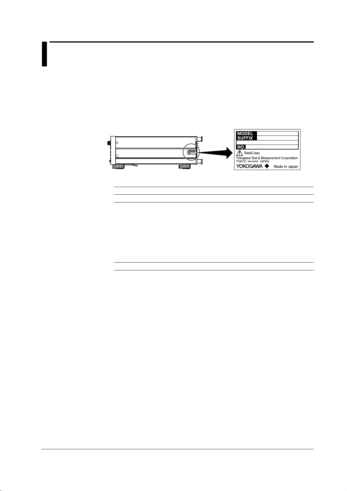
GS610
Check that the model name and suffix code given on the name plate on the side panel
match those on your order.
MODEL and SUFFIX Codes
Model Suffix Code1Description
765501 100-240 VAC Source measure unit
Power cord
Options /C10 Ethernet interface
1 For products whose suffix code contains “Z,” an exclusive manual may be included. Please
2 Make sure that the attached power cord meets the designated standards of the country and
2
-D UL/CSA Standard Power Cord (Part No.: A1006WD)
-F VDE Standard Power Cord (Part No.: A1009WD)
-Q BS Standard Power Cord (Part No.: A1054WD)
-R AS Standard Power Cord (Part No.: A1024WD)
-H GB Standard Power Cord (Part No.: A1064WD)
read it along with the standard manual.
area that you are using it in.
[Maximum rated voltage: 125 V; Maximum rated current: 7A]
[Maximum rated voltage: 250 V; Maximum rated current: 10 A]
[Maximum rated voltage: 250 V; Maximum rated current: 10 A]
[Maximum rated voltage: 250 V; Maximum rated current: 10 A]
[Maximum rated voltage: 250 V; Maximum rated current: 10 A]
IM 765501-01E
NO. (Instrument Number)
When contacting the dealer from which you purchased the instrument, please give them
the instrument number.
iii
Checking the Contents of the Package
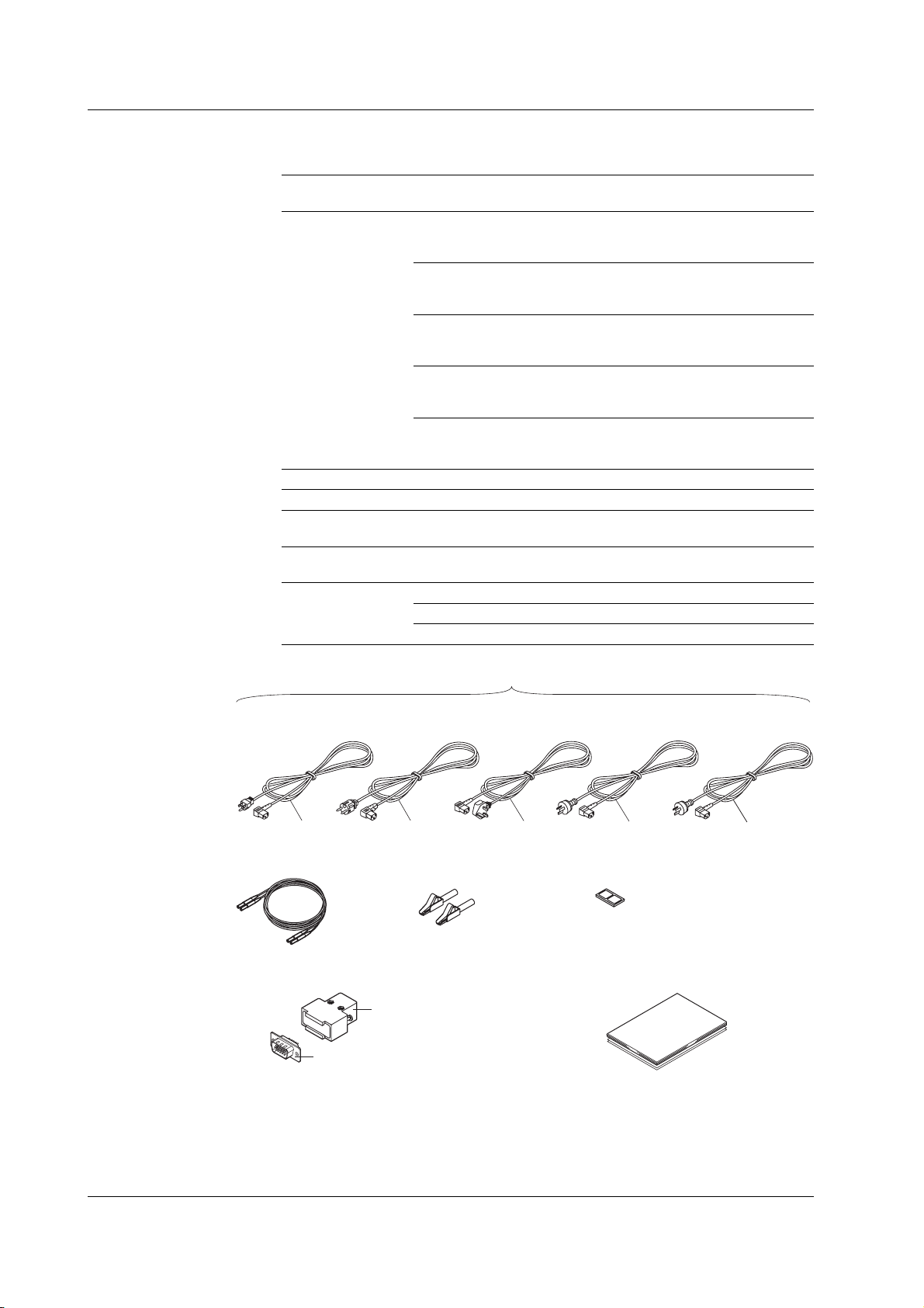
Standard Accessories
The standard accessories below are supplied with the instrument.
Name Model Qty. Notes
Power cord A1006WD 1 UL/CSA Standard Power Cord
Rubber Feet A9088ZM 2 Two rubber feet in one set
Measurement lead 758933 1
Alligator clip adapter 758922 1 set Safety terminal-to-alligator clip adapter. Red
D-sub connector for A1519JD/ 1 set 1 connector cover, 1
External I/O B8060KA 15-pin connectocer
Manuals IM 765501-01E 1 User’s manual (this manual)
/Part No.
Maximum rated voltage: 125 V;
Maximum rated current: 7A
A1009WD 1 VDE Standard Power Cord
Maximum rated voltage: 250 V;
Maximum rated current: 10 A
A1054WD 1 BS Standard Power Cord
Maximum rated voltage: 250 V;
Maximum rated current: 10 A
A1024WD 1 AS Standard Power Cord
Maximum rated voltage: 250 V;
Maximum rated current: 10 A
A1064WD 1 GB Standard Power Cord
Maximum rated voltage: 250 V;
Maximum rated current: 10 A
and black, 1 pc. each
IM 765501-92 1 Document for China
PIM 113-01Z2 1 List of worldwide contacts
One of these power cords is supplied according to the suffix code1.
UL, CSA Standard
A1006WD
D F
Measurement Lead
758933
D-sub connector for EXT. I/O
(15-pin, male)
B8060KA
1 Make sure that the attached power cord meets the designated standards of the country
and area that you are using it in.
VDE Standard
A1009WD
Alligator Clip Adapter Set
758922
A1519JD
BS Standard
A1054WD
Q
Manuals
• IM 765501-01E (this manual)
• IM 765501-92
• PIM 113-01Z2
AS Standard
A1024WD
R
Rubber Feet
A9088ZM
GB Standard
A1064WD
H
iv IM 765501-01E

Checking the Contents of the Package
Optional Accessories (Sold Separately)
The optional accessories below are available for purchase separately.
Name Model/ Min. Safety Notes Manual No.
Part No. Q’ty standard
Measurement lead 758917 1 set 1000 V CAT II Safety terminal cable with 2 leads (red and black) —
758933 1 set 1000 V CAT III Safety terminal cable with 2 leads (red and black) —
Alligator clip adapter 758922 1 set 300 V CAT II Safety terminal-to-alligator clip adapter. Red and —
(small) black, 1 pc each. Rating: 300 V, 15 A.
Alligator clip adapter 758929 1 set 1000V CAT II Safety terminal-to-alligator clip adapter. Red and —
(large) black, 1 pc each. Rating: 1000 V, 32 A.
Safety terminal adapter 758923 1 set 600 V CAT II Spring clamp type. Red and black, 1 pc. each. —
758931 1 set 1000 V CAT III Screw-in type. Red and black, 1 pc each. —
Conversion adapter 758924 1 500 V CAT II Safety BNC-to-banana adapter. Rating: 500 V. —
BNC cable 366924 1 — BNC-BNC, length: 1 m. Rating: 42 V. —
366925 1 — BNC-BNC, length: 2 m. Rating: 42 V. —
D-sub connector for A1519JD 1 — 15-pin connector cover —
External I/O B8060KA 1 — 15-pin connector —
in a set. Length: 0.75 m. Rating: 1000 V, 32 A.
in a set. Length: 1 m. Rating: 1000 V, 19 A.
Rating: 600 V, 10 A.
Rating: 1000 V, 36 A.
WARNING
• Use the accessories specified in this manual. Moreover, use the accessories of
this product only with Yokogawa products that specify them as accessories.
• Use the accessories of this product within the rated range of each accessory.
When using several accessories together, use them within the specification
range of the accessory with the lowest rating.
CAUTION
Use BNC cables 366924 and 366925 for the BNC I/O terminals.
French
AVERTISSEMENT
• Utiliser les accessoires spécifiés dans ce manuel. En outre, utiliser les
accessoires de ce produit uniquement avec des produits Yokogawa pour
lesquels ils sont spécifiés comme accessoires.
• Utilisez les accessoires de ce produit en fonction des valeurs nominales de
chacun.
Lorsque vous employez plusieurs accessoires en même temps, utilisez les
valeurs de l’accessoire ayant les valeurs nominales les plus faibles.
IM 765501-01E
ATTENTION
Utiliser les câbles BNC 366924 et 366925 pour les bornes E/S BNC.
v
Safety Precautions
This product is designed to be used by a person with specialized knowledge.
This instrument is an IEC safety class I instrument (provided with a terminal for
protective earth grounding). The general safety precautions described herein must be
observed during all phases of operation. If the instrument is used in a manner not
specified in this manual, the protection provided by the instrument may be impaired.
This manual is an essential part of the product; keep it in a safe place for future
reference. YOKOGAWA assumes no liability for the customer’s failure to comply with
these requirements.
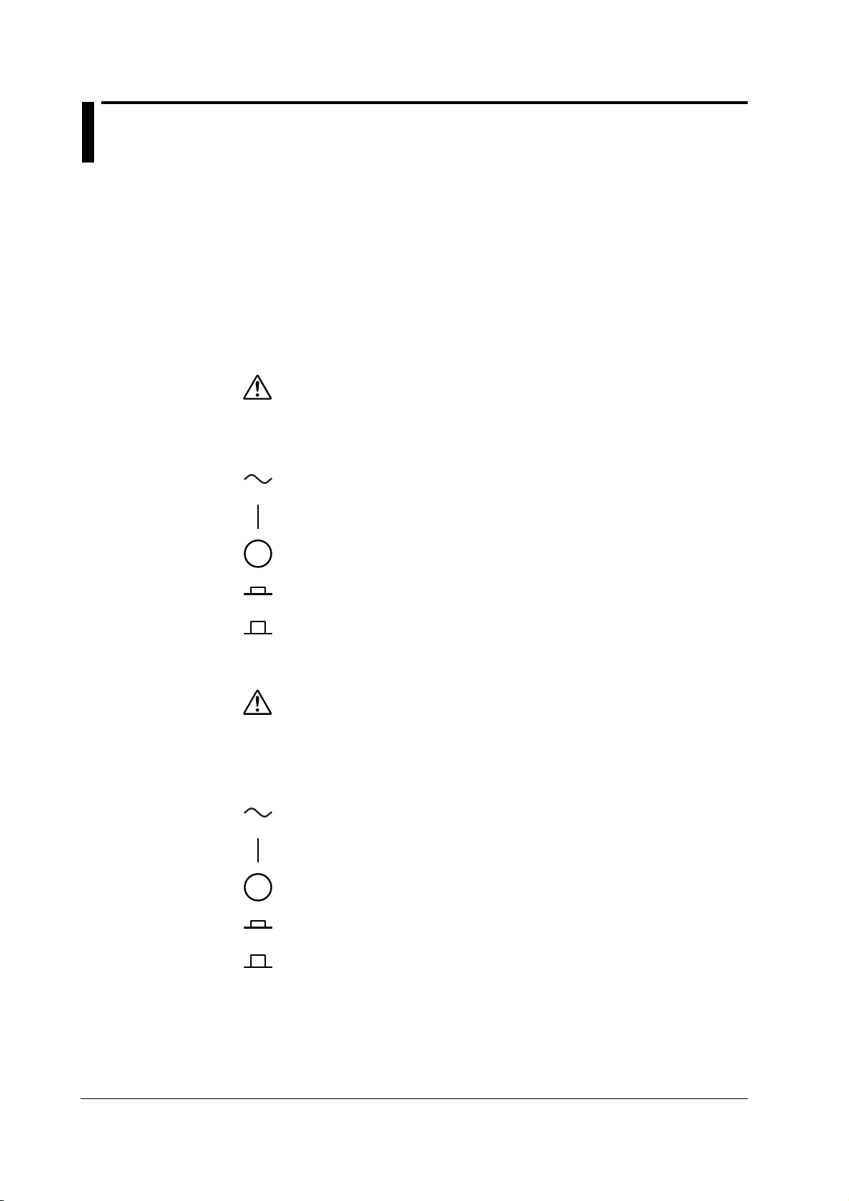
The following symbols are used on this instrument.
Warning: handle with care. Refer to the user’s manual or service manual.
This symbol appears on dangerous locations on the instrument which require
special instructions for proper handling or use. The same symbol appears in
the corresponding place in the manual to identify those instructions.)
Alternating current
ON (power)
French
OFF (power)
ON (power) state
OFF (power)
Avertissement : À manipuler délicatement. Toujours se reporter aux manuels
d’utilisation et d’entretien. Ce symbole a été apposé aux endroits dangereux
de l’instrument pour lesquels des consignes spéciales d’utilisation ou de
manipulation ont été émises. Le même symbole apparaît à l’endroit
correspondant du manuel pour identifier les consignes qui s’y rapportent.
Courant alternatif
Marche (alimentation)
Arrêt (alimentation)
Marche
Arrêt
vi IM 765501-01E

Safety Precautions
Failure to comply with the precautions below could lead to injury or death or damage
to the instrument.
WARNING
• Use the Instrument Only for Its Intended Purpose
This instrument is equipped with current and voltage measurement.
Use the instrument only for measuring and generating current and voltage.
• Check the Physical Appearance
Do not use the instrument if there is a problem with its physical appearance.
• Use the Correct Power Supply
Before connecting the power cord, ensure that the source voltage matches the
rated supply voltage of the instrument and that it is within the maximum rated
voltage of the provided power cord.
• Use the Correct Power Cord and Plug
• To prevent the possibility of electric shock or fire, be sure to use the power
cord supplied by YOKOGAWA.
• The main power plug must be plugged into an outlet with a protective earth
terminal. Do not disable this protection by using an extension cord without
protective earth grounding.
• Additionally, do not use the power cord supplied with this instrument with
another instrument.
• Do not use the power cord in a bundled condition.
• If you use a power plug with foreign substance on it, insulation may be
compromised by humidity or other factors and may cause a fire. Clean the
power plug regularly.
• Connect the Protective Grounding Terminal
Make sure to connect the protective earth to prevent electric shock before
turning ON the power. The power cord that comes with the instrument is a threeprong type power cord. Connect the power cord to a properly grounded threeprong outlet.
• Do Not Impair the Protective Grounding
Never cut off the internal or external protective grounding wire or disconnect the
wiring of the protective grounding terminal. Doing so poses a potential shock
hazard.
• Do Not Use When the Protection Functions Are Defective
Before using this instrument, check that the protection functions, such as the
protective grounding and fuse, are working properly. If you suspect a defect, do
not use the instrument.
• Do Not Operate in an Explosive Atmosphere
Do not operate the instrument in the presence of flammable liquids or vapors.
Operation in such an environment constitutes a safety hazard.
• Do Not Remove the Covers or Disassemble or Alter the Instrument
Only qualified YOKOGAWA personnel may remove the covers and disassemble
or alter the instrument. The inside of the instrument is dangerous because parts
of it have high voltages.
IM 765501-01E
vii

Safety Precautions
• Ground the Instrument before Making External Connections
Securely connect the protective grounding before connecting to the item under
measurement or to an external control unit.
Before touching the target device, turn off this instrument and check that there is
no voltage or current being output.
• Measurement Category
The measurement category of this instrument signal input terminals is Other (O).
Do not use it to measure the main power supply or for Measurement Categories
II, III, and IV.
• Install or Use the Instrument in Appropriate Locations
• This instrument is designed to be used indoors. Do not install or use it
outdoors.
• Install the instrument so that you can immediately remove the power cord if
an abnormal or dangerous condition occurs.
• Using in a Floating Condition
• Depending on the connected external device, dangerous voltage may appear
at the terminals if the instrument is used in a floating condition. Be careful of
electric shock and electric discharge.
• To prevent electric shock, remove rings, watches, and other metallic
accessories and jewelry before operation.
• Wiring Correctly
Dangerous voltage may appear at the terminals if the instrument is used in a
floating condition. If you do not connect the devices correctly, not only will it
damage the instrument or the target device, it may also lead to electric shock or
fire. Be careful when you connect the lead wires, and be sure to check the
following points.
• When using the instrument in a floating condition, make sure that the electric
potential of each output terminal is within ±250 Vpeak relative to the ground.
Before output (before turning on the output), check that:
• Lead wires are connected to the instrument’s output terminals correctly.
• Lead wires are connected to the target device correctly.
During output, check that:
• Never touch the terminals and the connected lead wires when the item under
measurement is on.
CAUTION
Operating Environment Limitations
This product is a Class A (for industrial environments) product. Operation of this
product in a residential area may cause radio interference in which case the
user will be required to correct the interference.
viii IM 765501-01E

Safety Precautions
French
AVERTISSEMENT
• Utiliser l’instrument aux seules fins pour lesquelles il est prévu
Cet instrument est équipé d'une fonction de mesure de courant et de tension.
Utiliser cet instrument uniquement pour mesurer et générer un courant et une
tension.
• Inspecter l’apparence physique
Ne pas utiliser l'instrument si son intégrité physique semble être compromise.
• Vérifier l’alimentation
Avant de brancher le cordon d’alimentation, vérifier que la tension source
correspond à la tension d’alimentation nominale du GS610 et qu’elle est
compatible avec la tension nominale maximale du cordon d’alimentation.
• Utiliser le cordon d'alimentation et la fiche adaptés
• Pour éviter les risques de choc électrique ou d’incendie, utilisez le cordon
d’alimentation fourni par YOKOGAWA.
• La fiche doit être branchée sur une prise secteur raccordée à la terre. En cas
d’utilisation d'une rallonge, celle-ci doit être impérativement reliée à la terre.
• Par ailleurs, n’utilisez pas le cordon d’alimentation fourni pour cet instrument
avec un autre appareil.
• N’utilisez pas le cordon d’alimentation en faisceau.
• Si vous utilisez un cordon d’alimentation sur lequel se trouve une substance
étrangère, l’isolation risque d’être compromise par l’humidité ou d’autres
facteurs, ce qui peut provoquer un incendie. Nettoyez la fiche du cordon
d’alimentation régulièrement.
• Brancher la prise de terre
Avant de mettre l’instrument sous tension, penser à brancher la prise de terre
pour éviter tout choc électrique. Le cordon d’alimentation livré avec l’instrument
est doté de trois broches. Brancher le cordon d’alimentation sur une prise de
courant à trois plots et mise à la terre.
• Ne pas entraver la mise à la terre de protection
Ne jamais neutraliser le fil de terre interne ou externe, ni débrancher la borne de
mise à la terre. Cela pourrait entraîner un choc électrique ou endommager
l’instrument.
• Ne pas utiliser lorsque les fonctions de protection sont défectueuses
Avant d’utiliser l’instrument, vérifier que les fonctions de protection, telles que le
raccordement à la terre et le fusible, fonctionnent correctement. En cas de
dysfonctionnement possible, ne pas utiliser l’instrument.
• Ne pas utiliser dans un environnement explosif
Ne pas utiliser l’instrument en présence de gaz ou de vapeurs inflammables.
Cela pourrait être extrêmement dangereux.
• Ne pas retirer le capot, ni démonter ou modifier l’instrument
Seul le personnel YOKOGAWA qualifié est habilité à retirer le capot et à
démonter ou modifier l’instrument. Certains composants à l’intérieur de
l’instrument sont à haute tension et par conséquent, représentent un danger.
IM 765501-01E
ix

Safety Precautions
• Relier l’instrument à la terre avant de le brancher sur des connexions
externes
Connectez le conducteur de terre avant de raccorder le dispositif cible ou une
unité de commande externe. Avant de toucher le dispositif cible, mettez
l’instrument hors tension, et vérifiez qu’aucune tension ni aucun courant ne sont
émis.
• Catégorie de mesure
La catégorie de mesure des terminaux d’entrée de signal du GS610 est Autre
(O). Ne pas l’utiliser pour mesurer l’alimentation électrique, ni pour les
catégories de mesure II, III et IV.
• Installer et utiliser l’instrument aux emplacements appropriés
• L’instrument est prévu pour une utilisation en intérieur. Ne pas l’installer, ni
l’utiliser à l’extérieur.
• Installer l’instrument de manière à pourvoir immédiatement le débrancher du
secteur en cas de fonctionnement anormal ou dangereux.
• Utilisation d’une condition de flottement
• Selon le dispositif extérieur raccordé, une tension dangereuse peut survenir
sur les bornes si l’instrument est utilisé en condition de flottement. Faites
attention au choc électrique et à la décharge électrique.
• Afin d’éviter tout choc électrique, retirer les bagues, les montres et autres
accessoires métalliques ainsi que les bijoux avant la mise en service.
• Câblage correct
Une tension dangereuse peut survenir sur les bornes si l’instrument est utilisé
en condition de flottement. Si vous ne raccordez pas correctement les appareils,
non seulement cela risque d’endommager l’équipement ou l’appareil cible, mais
en plus cela risque d’entraîner un choc électrique ou un incendie. Branchez
toujours les câbles en plomb correctement et vérifiez les points suivants.
• Lorsque l’instrument est utilisé en condition de flottement, veiller à ce que le
potentiel électrique de chaque borne de sortie soit inférieur à ± 250 V de
crête par rapport à la masse.
Avant le sortie (avant la mise sous tension), vérifier que :
• Les câbles en plomb sont correctement raccordés aux bornes de sortie de
l’équipement.
• Les câbles en plomb sont correctement raccordés à l’appareil cible.
Pendant la sortie, vérifier que :
• Ne jamais toucher les bornes et les câbles branchés lorsque l’appareil à
mesurer est sous tension.
ATTENTION
Limitations relatives à l’environnement opérationnel
Ce produit est un produit de classe A (pour environnements industriels).
L’utilisation de ce produit dans un zone résidentielle peut entraîner une
interférence radio que l'utilisateur sera tenu de rectifier.
x IM 765501-01E
Sales in Each Country or Region
Waste Electrical and Electronic Equipment
Waste Electrical and Electronic Equipment (WEEE), Directive
(This directive is valid only in the EU.)
This product complies with the WEEE directive marking requirement. This
marking indicates that you must not discard this electrical/electronic product in
domestic household waste.
Product Category
With reference to the equipment types in the WEEE directive, this product is
classified as a “Monitoring and control instruments” product.
When disposing of products in the EU, contact your local Yokogawa Europe B.V.
office. Do not dispose in domestic household waste.
EU Battery Directive
EU Battery Directive
(This directive is valid only in the EU.)
Batteries are included in this product. This marking indicates they shall be sorted
out and collected as ordained in the EU battery directive.
Battery type: Lithium battery
You cannot replace batteries by yourself. When you need to replace batteries,
contact your local Yokogawa Europe B.V. office.
Authorized Representative in the EEA
Yokogawa Europe B.V. is the authorized representative of Yokogawa Test &
Measurement Corporation for this product in the EEA. To contact Yokogawa Europe
B.V., see the separate list of worldwide contacts, PIM 113-01Z2.
IM 765501-01E
xi

Conventions Used in This Manual
Safety Markings
The following markings are used in this manual.
Improper handling or use can lead to injury to the user or damage
to the instrument.
indicate that the user must refer to the user’s manual for special
instructions. The same symbol appears in the corresponding place
in the user’s manual to identify those instructions. In the manual,
the symbol is used in conjunction with the word “WARNING” or
“CAUTION.”
This symbol appears on the instrument to
WARNING
CAUTION
French
AVERTISSEMENT
ATTENTION
Note
Calls attention to actions or conditions that could cause serious or
fatal injury to the user, and precautions that can be taken to prevent
such occurrences.
Calls attentions to actions or conditions that could cause light injury
to the user or damage to the instrument or user’s data, and
precautions that can be taken to prevent such occurrences.
Attire l’attention sur des gestes ou des conditions
susceptibles de provoquer des blessures graves (voire
mortelles), et sur les précautions de sécurité pouvant
prévenir de tels accidents.
Attire l’attention sur des gestes ou des conditions susceptibles
deprovoquer des blessures légères ou d’endommager l’instrument
ou lesdonnées de l’utilisateur, et sur les précautions de sécurité
susceptiblesde prévenir de tels accidents.
Calls attention to information that is important for proper operation
of the instrument.
xii IM 765501-01E

Subheadings
Conventions Used in This Manual
On pages that describe the operating procedures in chapters 3 through 17 and appendix,
the following symbols are used to distinguish the procedures from their explanations.
Procedure
Explanation
<<Corresponding Command Mnemonic>>
Follow the numbered steps. All procedures are written with
inexperienced users in mind; experienced users may not need to
carry out all the steps.
This subsection describes the setup parameters and the limitations
on the procedures. It may not give a detailed explanation of the
function. For a detailed explanation of the function, see chapter 2.
Indicates a communication command that corresponds to the
function described on the procedural explanation page.
Displayed Characters and Terminology Used in the Procedural Explanations
Panel Keys and Rotary Knob
Bold characters used in the procedural explanations indicate characters that are marked
on the panel key or the rotary knob.
SHIFT+Key
SHIFT+key
the operation key. In this state, the items marked in purple characters below the keys
are controlled.
means you will press the SHIFT key to turn ON the SHIFT key followed by
IM 765501-01E
xiii

Contents
List of Manuals ................................................................................................................................ i
Checking the Contents of the Package ..........................................................................................iii
Safety Precautions .........................................................................................................................vi
Sales in Each Country or Region ...................................................................................................xi
Conventions Used in This Manual................................................................................................. xii
Chapter 1 Part Names and Functions
1.1 Front Panel ...................................................................................................................... 1-1
1.2 Rear Panel ....................................................................................................................... 1-2
1.3 Names and Description of the Displayed Contents ......................................................... 1-3
1.4 Key Groups and Menus ................................................................................................... 1-5
Chapter 2 Explanation of Functions
2.1 System Configuration and Block Diagram ....................................................................... 2-1
2.2 Source Measure Cycle ..................................................................................................... 2-3
2.3 Source .............................................................................................................................. 2-5
2.4 Measurement ................................................................................................................. 2-10
2.5 Triggers .......................................................................................................................... 2-13
2.6 Sweep ............................................................................................................................ 2-14
2.7 Computation ................................................................................................................... 2-17
2.8 Store and Recall (Statistical Computation Value Display).............................................. 2-19
2.9 USB Storage Function ................................................................................................... 2-20
2.10 Other Functions ............................................................................................................. 2-22
Chapter 3 Instrument Preparation and Common Operations
3.1 Handling Precautions ....................................................................................................... 3-1
3.2 Installing the GS610 ......................................................................................................... 3-3
3.3 Connecting to the Power Supply ...................................................................................... 3-7
3.4 Turning the Power Switch ON/OFF .................................................................................. 3-9
3.5 Wiring Precautions ......................................................................................................... 3-11
3.6 Setting the Power Frequency ......................................................................................... 3-14
3.7 Setting the Date, Time, and the Time Difference from GMT (Greenwich Mean Time) ... 3-15
3.8 Basic Operation of Keys and Rotary Knob .................................................................... 3-17
3.9 Entering Values .............................................................................................................. 3-19
Chapter 4 Trigger Setting, Connection Type (Remote Sense and Local Sense),
and USB Storage Function
4.1 Setting the Trigger ............................................................................................................ 4-1
4.2 Connection Type (Remote Sense and Local Sense) ....................................................... 4-3
4.3 USB Storage Function ..................................................................................................... 4-5
Chapter 5 Source
5.1 Switching the Source Function ........................................................................................ 5-1
5.2 Setting the Source Range Setting .................................................................................... 5-2
5.3 Setting the Limiter ............................................................................................................ 5-4
5.4 Setting the DC Source Mode ........................................................................................... 5-6
5.5 Setting the Pulse Source Mode ....................................................................................... 5-8
5.6 Setting the Source Delay ............................................................................................... 5-11
5.7 Turning the Output ON/OFF........................................................................................... 5-13
xiv IM 765501-01E

Contents
3
12
11
10
15
14
13
18
17
16
Index
App
5.8 Zero Generation ............................................................................................................. 5-14
5.9 Offset Calibration ........................................................................................................... 5-16
Chapter 6 Sweep
6.1 Setting the Linear or Log Sweep ...................................................................................... 6-1
6.2 Setting the Program Sweep ............................................................................................. 6-5
6.3 Selecting the Termination Mode ....................................................................................... 6-7
6.4 Setting the Repeat Count ................................................................................................. 6-9
6.5 Starting the Sweep Operation ........................................................................................ 6-10
6.6 Program Pattern File ...................................................................................................... 6-11
Chapter 7 Measurement
7.1 Turning the Measurement ON/OFF ................................................................................. 7-1
7.2 Selecting the Measurement Function .............................................................................. 7-2
7.3 Turning ON/OFF the Auto Range function of the Measurement Range Settings ............ 7-3
7.4 Setting the Measurement Delay ....................................................................................... 7-4
7.5 Setting the Integration Time ............................................................................................. 7-6
7.6 Auto Zero Function .......................................................................................................... 7-7
7.7 Turning Auto V/I ON/OFF ................................................................................................. 7-8
Chapter 8 Computation
8.1 Averaging ......................................................................................................................... 8-1
8.2 NULL Computation ........................................................................................................... 8-3
8.3 Computation Using Equations ......................................................................................... 8-4
8.4 Comparison Operation ..................................................................................................... 8-7
8.5 User-Defined Computation .............................................................................................. 8-9
1
2
3
4
5
6
7
8
9
10
Chapter 9 Storing Measured Results and Recalling Statistical Computation
Values
9.1 Storing the Measured Results .......................................................................................... 9-1
9.2 Recalling Statistical Computation Values ......................................................................... 9-4
Chapter 10 BNC Input/Output and External Input/Output
10.1 Setting the Input/Output Signals of the BNC Input/Output Terminal and the External Input/
Output Connector ........................................................................................................... 10-1
10.2 Synchronized Operation ................................................................................................ 10-7
Chapter 11 Other Functions
11.1 Saving the Setup Data ................................................................................................... 11-1
11.2 Loading the Setup Data ................................................................................................. 11-3
11.3 Selecting the Settings Applied at Power ON .................................................................. 11-4
11.4 Turning the Beep Sound ON/OFF .................................................................................. 11-5
11.5 Displaying the Error Log ................................................................................................ 11-6
11.6 Selecting the Display Brightness and Turning the Display OFF .................................... 11-7
11.7 Key Lock ........................................................................................................................ 11-8
11.8 Selecting the Decimal Point and Separator Notations of CSV Files .............................. 11-9
Chapter 12 Ethernet Interface (Option)
12.1 Ethernet Interface Functions and Specifications ............................................................ 12-1
12.2 Connecting to the Network ............................................................................................. 12-2
12.3 Setting the TCP/IP ......................................................................................................... 12-3
12.4 Checking the Ethernet Settings ..................................................................................... 12-6
12.5 Web Server Function ..................................................................................................... 12-7
IM 765501-01E
11
12
13
14
15
16
17
18
App
Index
xv

Contents
Chapter 13 GP-IB Communications
13.1 About the IEEE.488.2-1992 Standard ............................................................................ 13-1
13.2 GP-IB Interface Functions and Specifications ............................................................... 13-3
13.3 Connecting the GP-IB Cable .......................................................................................... 13-4
13.4 Setting the GP-IB Address ............................................................................................. 13-5
13.5 Responses to Interface Messages ................................................................................. 13-6
Chapter 14 RS-232 Communications
14.1 RS-232 Interface Functions and Specifications ............................................................. 14-1
14.2 Serial (RS-232) Interface Connection ............................................................................ 14-2
14.3 Handshaking Method ..................................................................................................... 14-4
14.4 Combination of Data Formats ........................................................................................ 14-5
14.5 Setting the RS-232 Interface .......................................................................................... 14-6
Chapter 15 USB Interface
15.1 USB Interface Functions and Specifications .................................................................. 15-1
15.2 Selecting the USB Interface Function ............................................................................ 15-2
Chapter 16 Communication Commands
16.1 Program Format ............................................................................................................. 16-1
16.1.1 Symbols Used in the Syntax ........................................................................... 16-1
16.1.2 Messages ........................................................................................................ 16-1
16.1.3 Commands ...................................................................................................... 16-3
16.1.4 Responses ...................................................................................................... 16-5
16.1.5 Data................................................................................................................. 16-5
16.2 Commands ..................................................................................................................... 16-6
16.2.1 A List of Commands ........................................................................................ 16-6
16.2.2 Output Commands (OUTPut Group)............................................................. 16-14
16.2.3 Source Commands (SOURce GRoup).......................................................... 16-15
16.2.4 Sweep Commands (SWEep Group) ............................................................. 16-23
16.2.5 Measurement Commands (SENSe GRoup) ................................................. 16-24
16.2.6 Trigger Commands (TRIGger Group) ........................................................... 16-26
16.2.7 Computation Commands (CALCulate Group)............................................... 16-27
16.2.8 Store/Recall Commands (TRACe Group) ..................................................... 16-29
16.2.9 External Input/Output Commands (ROUTe Group)....................................... 16-31
16.2.10 System Commands (SYSTem Group)........................................................... 16-34
16.2.11 Measured Value Read Commands (INITiate, FETCh, and READ Group) .... 16-38
16.2.12 Status Commands (STATus Group) .............................................................. 16-39
16.2.13 Common Command Group ........................................................................... 16-40
16.3 Status Reports ............................................................................................................. 16-42
16.3.1 Overview of the Status Report ...................................................................... 16-42
16.3.2 Status Byte .................................................................................................... 16-43
16.3.3 Standard Event Register ............................................................................... 16-44
16.3.4 Source Event Register .................................................................................. 16-46
16.3.5 Measure Event Register................................................................................ 16-47
16.3.6 Output Queue and Error Queue .................................................................... 16-48
16.4 Sample Programs ........................................................................................................ 16-49
16.4.1 Before Programming ..................................................................................... 16-49
16.4.2 GP-IB Access Function ................................................................................. 16-50
16.4.3 Sample 1 (Example of Reading the Measured Results during Free Run Using
Internal Trigger) ............................................................................................. 16-53
xvi IM 765501-01E

Contents
3
12
11
10
15
14
13
18
17
16
Index
App
16.4.4 Sample 2 (Example of generating a trigger from the PC and reading the
measured results) ......................................................................................... 16-55
16.4.5 Sample 3 (Example of Updating the Source Level from a PC) ..................... 16-57
16.4.6 Sample 4 (Example of Updating the Source Level with
the Sweep Function) ..................................................................................... 16-59
16.4.7 Sample 5 (Example of Carrying Out the Storage Function and Reading the
Statistical Values) .......................................................................................... 16-62
16.5 ASCII Character Codes ............................................................................................... 16-63
Chapter 17 Troubleshooting and Maintenance
17.1 Troubleshooting ............................................................................................................. 17-1
17.2 Error Code Description and Corrective Action ............................................................... 17-3
17.3 Self Test ......................................................................................................................... 17-6
17.4 Checking the System Status .......................................................................................... 17-8
17.5 Updating the System Firmware ...................................................................................... 17-9
17.6 Recommended Replacement Parts ............................................................................. 17-11
Chapter 18 Specifications
18.1 Source Section ............................................................................................................... 18-1
18.2 Measurement Section .................................................................................................... 18-3
18.3 Functions ....................................................................................................................... 18-4
18.4 External Input/Output Section (TRIG/SWEEP/CTRL IN and OUT)................................ 18-5
18.5 Interface ......................................................................................................................... 18-5
18.6 General Specifications ................................................................................................... 18-6
18.7 External Dimensions ...................................................................................................... 18-9
1
2
3
4
5
6
7
8
9
10
Appendix
Appendix 1 Computation Definition Specifications ..................................................................App-1
Appendix 2 Application Examples ...........................................................................................App-6
Appendix 3 Contents of the Factory Default Setup File (Default.txt) .....................................App-18
11
Index
IM 765501-01E
12
13
14
15
16
17
18
App
Index
xvii
GS 61 0
SOU RCE MEAS URE UNIT
Chapter 1 Part Names and Functions
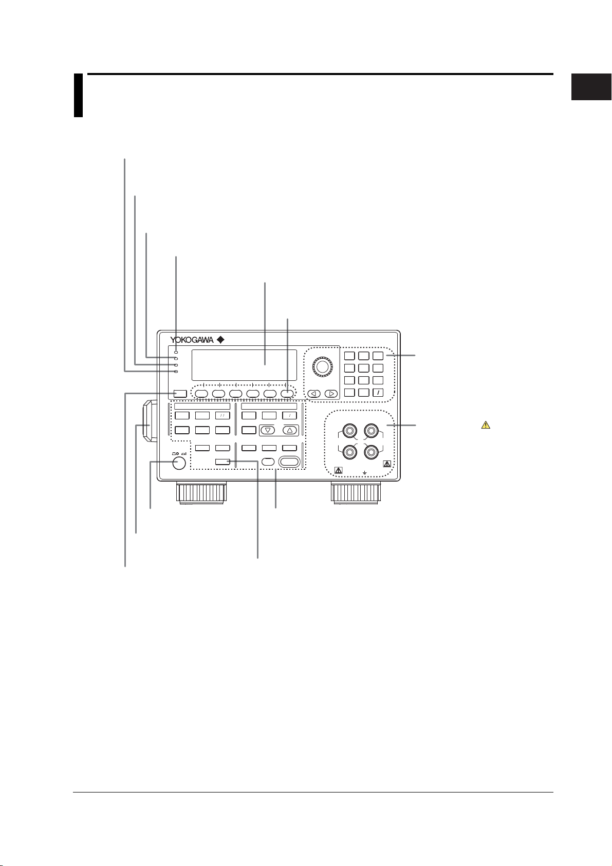
1.1 Front Panel
Remote indicator
Illuminates when the GS610 is in remote mode (controlled via communications).
See sections 13.2 and 14.1.
KEY LOCK indicator
Illuminates when key lock is ON.
See section 11.7.
Remote sense indicator
Illuminates when remote sense (four-terminal connection).
See section 4.2.
Average indicator
Illuminates when averaging is ON. See section 8.1.
GS610
AUTO
RANGE
MATH
COMPARE
LOCAL
MISC
SOURCE MEASURE UNIT
I
Ω
V
MEASURE
NULL
VALUE
TIME
KEY LOCK
SHIFT
AVERAGE
4 WIRE
KEY LOCK
REMOTE
DISPLAY
ESC
STORE
MENU
RECALL
POWER
MEASURE
Display
See section 1.3.
SOURCE
LIMIT
MODE
MENU
RANGE
AUTO
RANGE
OUTPUT CONTROL
START
SWEEP
ZERO
Soft keys
Used to select items on the soft key menu that appears
when setting up the GS610. See section 3.8.
VS IS
SOURCE
TRIG
MODE
OUTPUT
789
456
BS
123
.
0
SENSE
Hi
110V
1V
MAX
MAX
Lo
ALL TERMINALS
250V MAX TO
+
OUTPUT
-
110V
MAX
Rotary knob, numeric keys, and
cursor keys
Used to set values and select setup
data or items.
See sections 3.8 and 3.9.
Output terminal
Connect the measurement lead that
comes with the package.
See sections 3.5 and 4.2.
1
Part Names and Functions
IM 765501-01E
Power switch.
See section 3.4.
Handle
Used when carrying the GS610.
See section 3.1.
ESC (DISPLAY) key
Used to clear the soft key menu.
See section 3.8.
Setup and execution keys
Keys used to change the settings or carry out an operation.
Press a setup key to show the respective setup item.
See sections 1.4 and 3.9.
SHIFT key
The keys enter the shifted state when you press the SHIFT key and
the SHIFT key illuminates. In this state, the items marked in purple
characters below the keys are controlled.
1-1
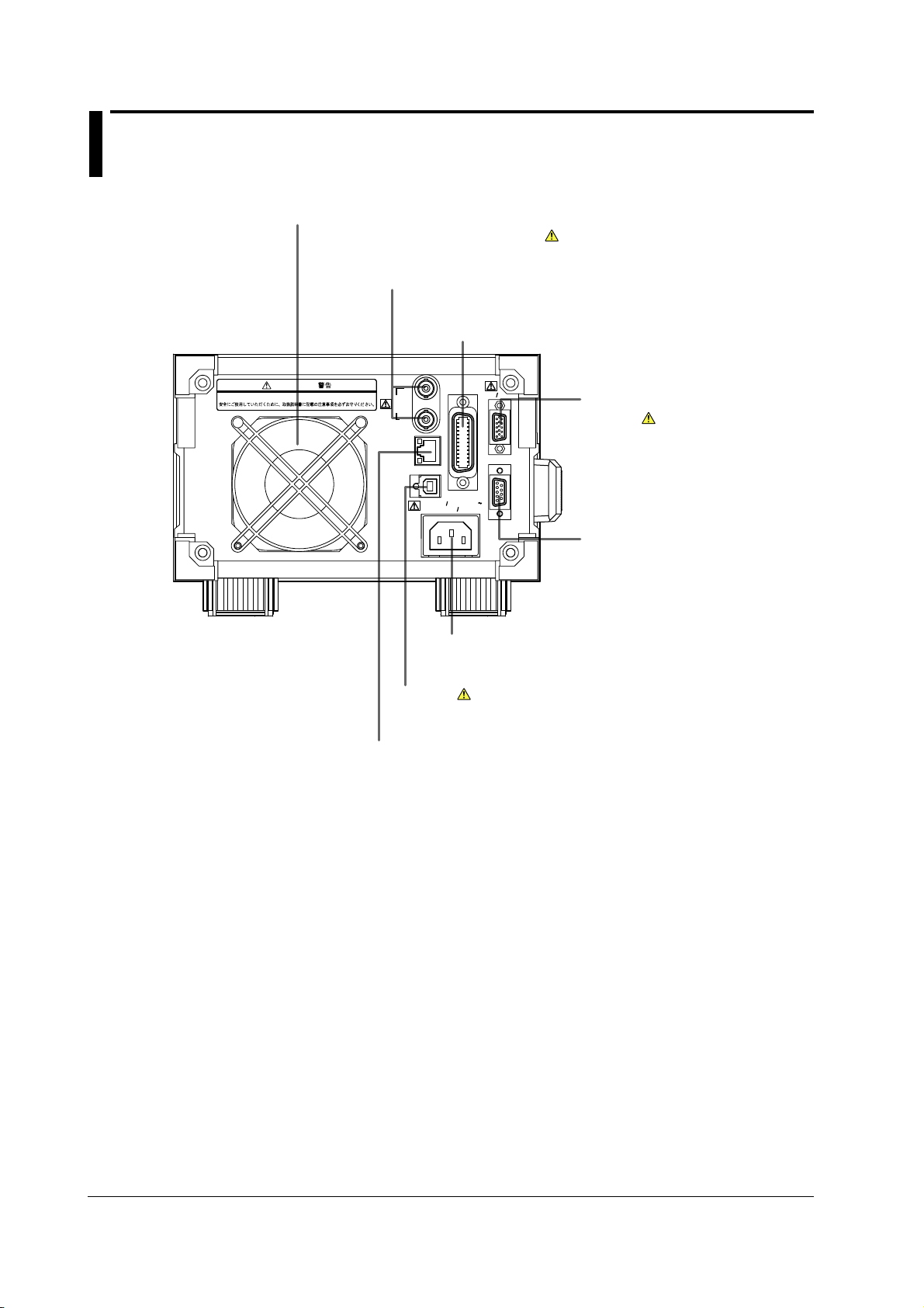
1.2 Rear Panel
Cooling fan
See section 3.2.
BNC input/output terminal
Used to input/output signals such as trigger, sweep, and control
signals and deliver the output signal of the comparison result.
See chapter 10.
GP-IB connector
Used to perform communications via the GP-IB interface.
See section 13.3.
Do not operate without reading the safety precautions in the user’s manual.
WARNING
100 - 120V
200VA MAX
GP-IB
(IEEE488)
220 - 240V AC
60Hz
50
EXT I
O
SERIAL (RS-232)
External input/output connector
(15 pins)
Used to input/output signals such
as trigger, sweep, and control
signals and deliver the output signal
of the comparison result.
See chapter 10.
TRIG /
SWEEP /
CTRL
ETHERNET
100BASE-TX
USB
IN
OUT
ACT
LINK
RS-232 connector (9 pins)
Used to perform communications
with a PC via the RS-232 interface.
See section 14.2.
Power connector
Used to connect the GS610 to a power supply.
See section 3.3.
USB port
Used to connect to a PC with a USB interface when running
the GS610 as a USB storage device.
Ethernet port
Used to connect to a LAN.
1-2 IM 765501-01E
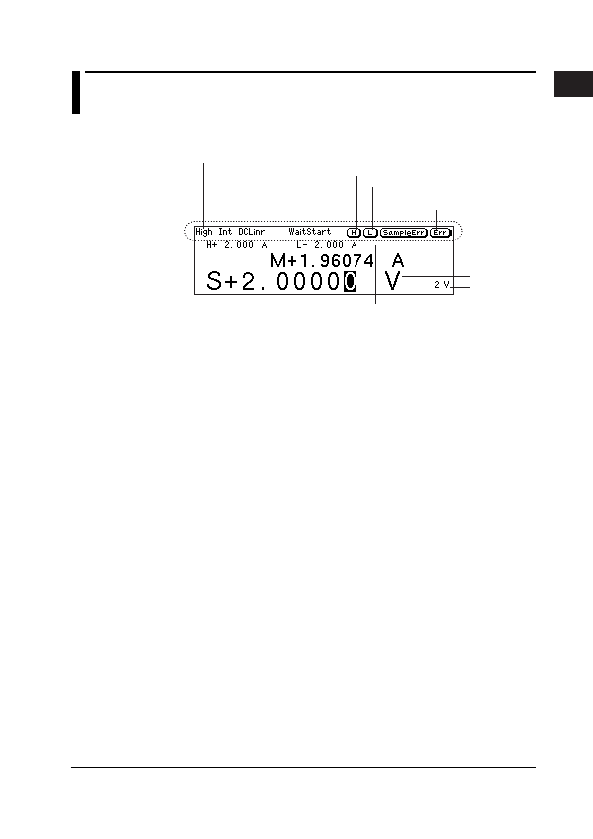
1.3 Names and Description of the Displayed Contents
The contents shown on the display are as follows:
Status display area
Comparison result display
Trigger setting display
Source mode and sweep
mode displays
Wait indicator
High limiter indicator
Low limiter indicator
Sampling error indicator
Error indicator
1
Part Names and Functions
Measured value
Source value
Source range
High limiter value
Information Shown in the Status Display Area
Comparison Result Display (For the procedures, see section 8.4)
Displays the judgement result of the comparison.
High: Over the upper limit
In: Within the limits
Low: Under the lower limit
Trigger Mode Display (For the procedures, see section 4.1)
Displays the selected trigger mode.
Int: Internal trigger
Ext: External trigger
Imm: Immediate (no trigger wait)
Source Mode and Sweep Mode Displays (For the procedures, see sections 5.4, 5.5,
6.1, and 6.2)
Displays the combination of the source mode and sweep mode. The following eight
combinations are available.
DC: DC source
Pls: Pulse source
DCLinr: Source mode = DC and sweep mode = Linear
DCLog: Source mode = DC and sweep mode = Log
DCProg: Source mode = DC and sweep mode = Program
PlsLinr: Source mode = pulse and sweep mode = Linear
PlsLog: Source mode = pulse and sweep mode = Log
PlsProg: Source mode = pulse and sweep mode = Program
Low limiter value
IM 765501-01E
Wait Indicator (For the procedures, see section 2.5 and 6.5)
Displays the various wait conditions during operation.
WaitTrigger: Waiting for trigger
WaitStart: Waiting for sweep start
Calculating: Calculating sweep data
1-3

1.3 Names and Description of the Displayed Contents
High Limiter Indicator (For the procedures, see section 5.3)
Turns ON when the high limiter is active.
Low Limiter Indicator (For the procedures, see section 5.3)
Turns ON when the low limiter is active.
Sampling Error Indicator (For the procedures, see section 2.5)
Turns ON when the trigger timing is not synchronized to the source measure cycle
period (the starting point) such as when a trigger is activated in the middle of a source
measure cycle.
Error Indicator (For the procedures, see section 11.5)
Turns ON when there is one or more errors in the error memory.
1-4 IM 765501-01E
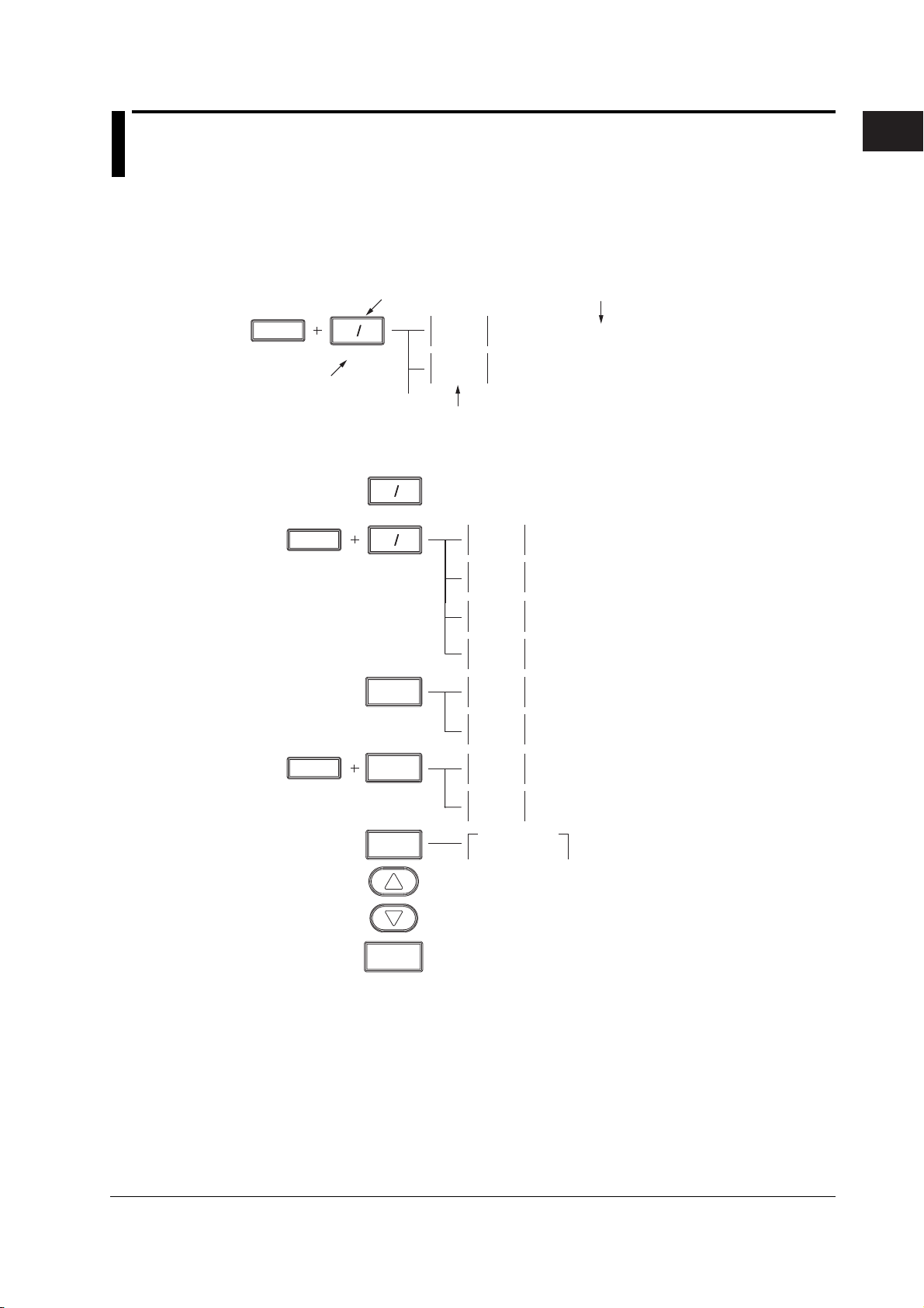
1.4 Key Groups and Menus
There are four functional key groups on the GS610. This section introduces each key
group in a tree format.
Viewing the Tree Structure
1
Part Names and Functions
SHIFT
Activated when the
SHIFT key is pressed
followed by the key
VS IS
SOURCE
SOURCE Group
SHIFT
SHIFT
Keys
VS IS
SOURCE
VS IS
SOURCE
LIMIT
MENU
LIMIT
MENU
MODE
Setup description and reference section
Pulse
Base
Zero
Offset
Switches the source function (voltage (VS) or current (IS))
(section 5.1)
Sets the pulse base when generating pulses (section 5.2)
Sets the zero source offset (section 5.8)
Soft key menu shown on the display
Pulse
Base
Zero
Offset
Zero Z
Hiz Loz
Cal
Exec
High
Limit
Low
Limit
Limit
On Off
Tracking
On Off
SourceMode
DC Pulse
Sets the pulse base when generating pulses
(section 5.5)
Sets the zero source offset (section 5.8)
Switches the zero source impedance
(high or low) (section 5.8)
Executes offset calibration (section 5.9)
Sets the upper limiter value (section 5.3)
Sets the lower limiter value (section 5.3)
Turns ON/OFF the limiter (section 5.3)
Turns ON/OFF the limiter tracking (section 5.3)
Selects the source mode (DC or pulse)
(sections 5.4 and 5.5)
IM 765501-01E
AUTO
RANGE
Increases the source range (section 5.2)
Decreases the source range (section 5.2)
Turns ON/OFF the auto source range (section 5.2)
1-5
1.4 Key Groups and Menus
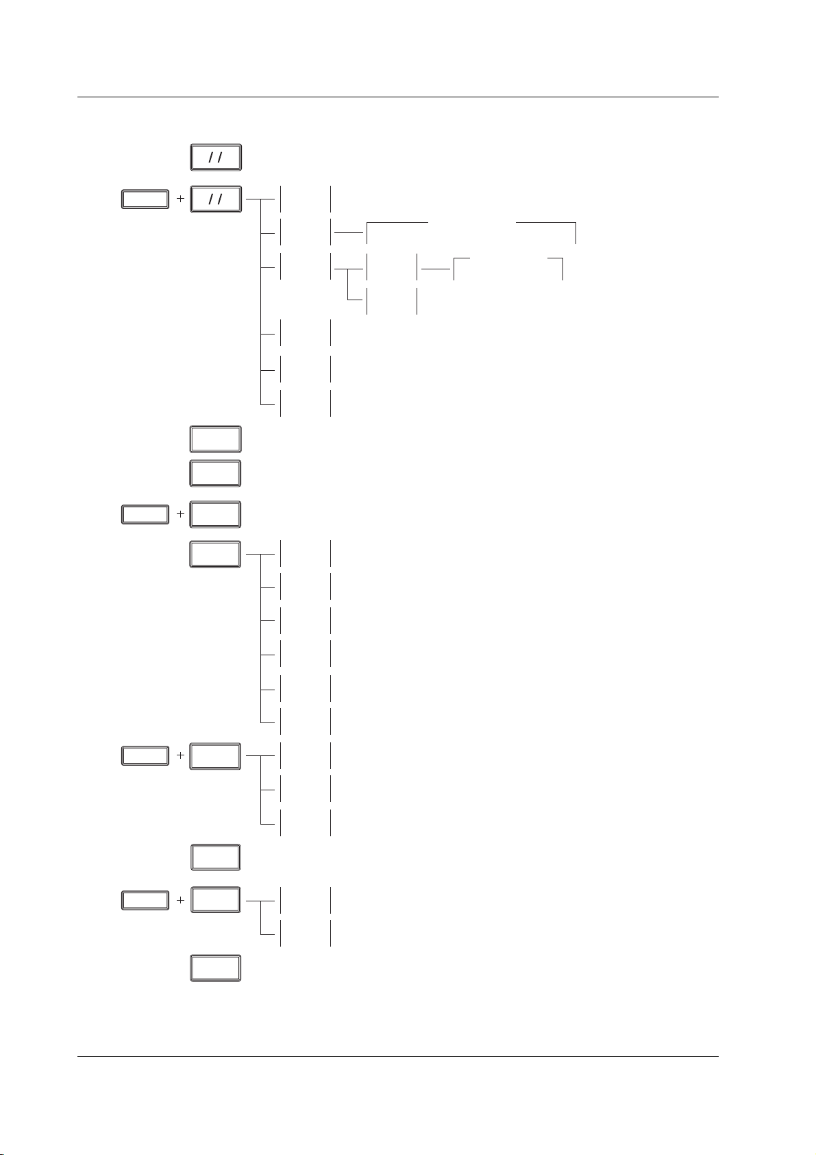
MEASURE Group
I
V
Ω
MEASURE
I
V
SHIFT
Ω
MEASURE
Switches the measurement function (voltage (V), current (I), or resistance (Ω) (section 7.2)
Measure
On Off
IntgTime
Average
AutoZero
On Off
Turns ON/OFF the measurement function (section 7.1)
***
***
250µs 1ms 4ms *** 100ms 200ms
Mode
***
Count
***
Turns ON/OFF the auto zero function (section 7.6)
IntegrationTime
AverageMode
Off Block Moving
Sets the average count (section 8.1)
Sets the integration time
(section 7.5)
Switches the average mode
(Off, Block, or Moving)
(section 8.1)
SHIFT
SHIFT
AUTO
RANGE
NULL
VALUE
NULL
VALUE
MATH
COMPARE
MATH
COMPARE
AutoZero
Exec
Auto V/I
On Off
Turns ON/OFF the auto measurement range (section 7.3)
Turns ON/OFF the NULL computation (section 8.2)
Sets the NULL reference (section 8.2)
Math
On Off
Param
Param
Param
View
Select
File
Compare
On Off
Upper
Execute auto zero (section 7.6)
Turns ON/OFF auto V/I (section 7.7)
Turns ON/OFF computation (section 8.3)
Sets equation parameter A (section 8.3)
A
Sets equation parameter B (section 8.3)
B
Sets equation parameter C (section 8.3)
C
Displays the equation (section 8.3)
Selects the equation definition file (section 8.3)
Turns ON/OFF the comparison operation (section 8.4)
Sets the upper limit of the comparison operation (section 8.4)
SHIFT
STORE
MENU
STORE
MENU
RECALL
Lower
Turns ON/OFF the storage function (section 9.1)
Count
Auto
On Off
Displays the statistical computation result (section 9.2)
Sets the lower limit of the comparison operation (section 8.4)
***
Sets the number of points to be stored (store count) (section 9.1)
Turns ON/OFF the auto storage function (section 9.1)
1-6 IM 765501-01E
1.4 Key Groups and Menus
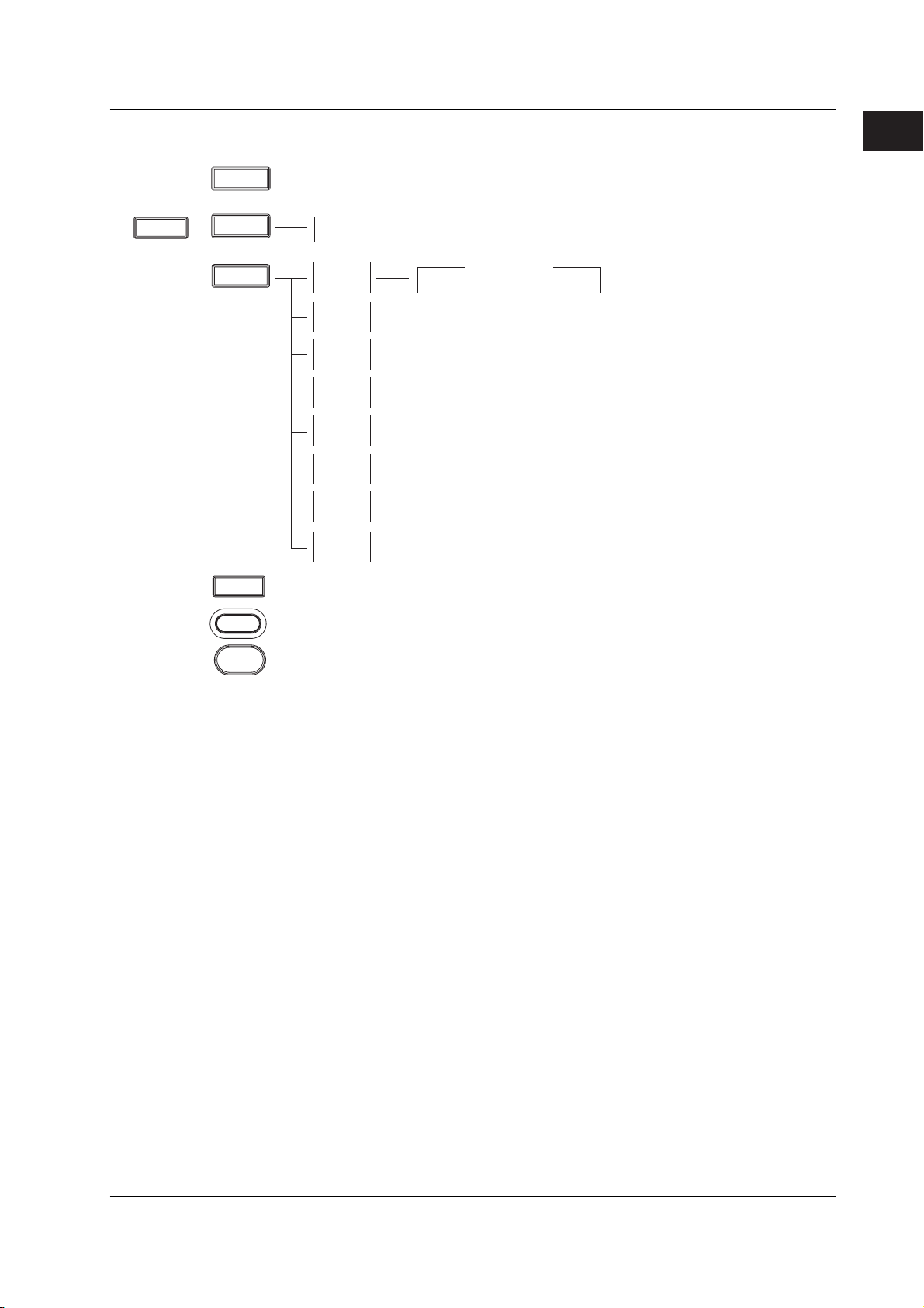
OUTPUT CONTROL Group
SHIFT
TRIG
MODE
TRIG
MODE
Generates a manual trigger (section 4.1)
SWEEP
START
Starts the sweep operation (section 6.5)
TrigMode
Int Ext Imm
Mode
***
Last
Rtn Keep
Repeat
Start
Value
Stop
Value
Step
Value
Step
Count
Select
File
Switches the sweep termination mode (return on keep) (section 6.3)
Sets the sweep repeat count (section 6.4)
***
Sets the sweep start value (section 6.1)
Sets the sweep stop value (section 6.1)
Sets the sweep step value (displayed only when linear sweep is selected)
(section 6.1)
Sets the sweep step count (displayed only when log sweep is selected)
(section 6.1)
Selects the pattern file (displayed only when program sweep is selected)
(section 6.2)
Selects the trigger mode (internal, external, or immediate) (section 4.1)
SweepMode
Off Linear Log Program
Selects the sweep mode
(off, linear, log, or program)
(sections 6.1 and 6.2)
1
Part Names and Functions
OUTPUT
ZERO
Turns ON/OFF the output mode (section 5.7)
Turns ON/OFF the zero state (section 5.8)
IM 765501-01E
1-7

1.4 Key Groups and Menus
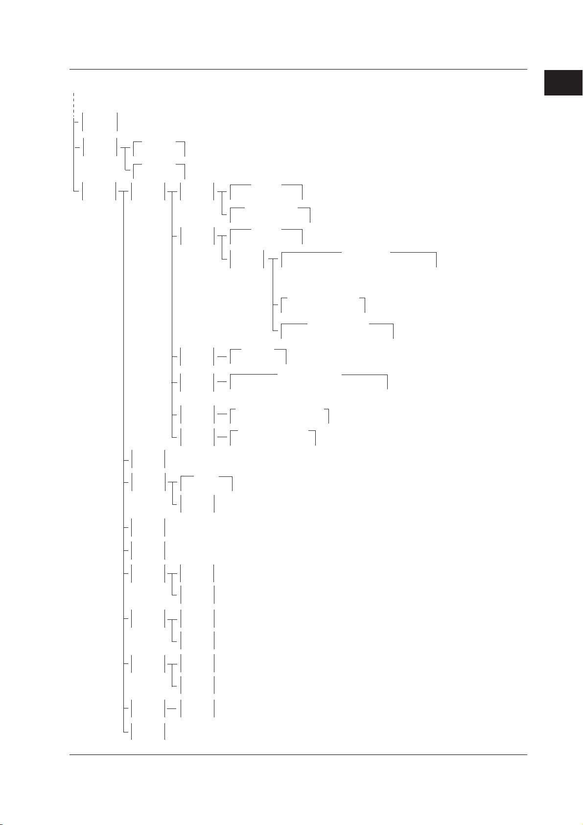
MISC Group
TIME
KEY LOCK
SHIFT
TIME
KEY LOCK
Turns ON/OFF key lock (section 11.6)
MISC
S.Delay
***
M.Delay
***
Period
***
P. Wi dth
***
Remote
I/F
Setup
Error
Log
Sets the source delay (section 5.6)
Sets the measure delay (section 7.4)
Sets the repeat period of the internal trigger (section 4.1)
Sets the pulse width (section 5.5)
GPIB
RS232
LAN
USB
Save
Setup
Load
Setup
PowerOn
Setup
Clear
Sets the GP-IB address (section 13.4)
***
BaudRate
***
DataBit
7 8
Parity
***
StopBit
1 2
Flow
***
Term
***
DHCP
On Off
IP
Address
Subnet
Mask
Default
Gateway
Term
***
Overview
USB Mode
***
Storage USB-TMC
Save
RamDisk
Save
Setup1
Save
Setup2
Save
Setup3
Save
Setup4
Loads the setup (section 11.2)
Selects the setup used when the GS610 is powered up (section 11.3)
Shows and clears error log (section 11.5)
9600 14400 19200 38400 57600 115200
Switches the RS-232 data length (7 or 8) (section 14.5)
Parity
None Even Odd
Switches the RS-232 stop bit (1 or 2) (section 14.6)
FlowControl
None XON CTS/RTS
Terminator
CR LF CR+LF
Turns ON/OFF the Ethernet DHCP function (section 12.3)
Enter
Enter
Enter
Terminator
CR LF CR+LF
Shows a list of Ethernet settings (section 12.4)
Selects the USB function (storage function
or USB communication function)
(section 15.2)
Saves the settings to the RAM disk (GS610RAM)
(section 11.1)
Saves the settings to Setup 1 (section 11.1)
Saves the settings to Setup 2 (section 11.1)
Saves the settings to Setup 3 (section 11.1)
Saves the settings to Setup 4 (section 11.1)
BaudRate
Selects the RS-232 parity
(none, odd, or even) (section 14.5)
Selects the RS-232 transmission
delimiter (CR, LF, or CR+LF)
(section 14.5)
Sets the fixed Ethernet IP address
(section 12.3)
Sets the fixed Ethernet subnet mask
(section 12.3)
Sets the fixed Ethernet default gateway
(section 12.3)
Sets the Ethernet transmission
delimiter (CR, LF, or CR+LF)
(section 12.3)
Selects the
RS-232
baud rate
(section 14.5)
Selects the RS-232 flow control
(none, XON-OFF, CTS-RTS)
(section 14.5)
Continues to the next page
1-8 IM 765501-01E
1.4 Key Groups and Menus
Continued from the previous page
Wire
2W 4W
CSV
Setting
Selects sensing (two-wire or four-wire) (section 4.2)
DecPoint
. ,
Separate
, ;
System
External
I/O
Beep
On Off
Display
***
LineFreq
50 60
Product
Info
Time
Adjust
Turns ON/OFF the beep sound (section 11.4)
Selects the power frequency (50 Hz or 60 Hz) (section 3.6)
Shows the product information (section 17.4)
Selects the decimal point for CSV files (section 11.8)
Selects the separator for CSV files (section 11.8)
BNC IN
***
BNC OUT
***
DIO5
***
DIO6
***
DIO7
***
DIO8
***
Bright
1 2 3 4
Off
Exec
Edit
Turns OFF the display (section 11.6)
Edits the time (section 3.7)
BNC IN
Trig Sweep Ctrl
ControllType
IntLock Output Zero
BNC OUT
Trig Sweep Ctrl
Type
***
DIO 5pin
Output Zero
DIO 6pin(TrigOut)
Origin ScrChg MeasBgn MeasEnd PlsEnd
DIO 7pin(SweepSyncOut)
Origin TurnEnd AllEnd
DIO 8pin(ControlOut)
IntLock Output Zero
Selects the display brightness (section 11.6)
Selects the BNC input
(trigger, sweep start, or control) (section 10.1)
Selects the BNC control input
(interlock, output relay control, or zero source) (section 10.1)
Selects the BNC output (trigger, sweep start, or control)
(section 10.1)
Origin ScrChg MeasBgn MeasEnd PlsEnd
SweepSyncOutType
Origin TurnEnd AllEnd
ControlOutType
IntLock Output Zero Program
Selects the external input/output connector pin 5 function
(output relay control or zero source control) (section 10.1)
Selects the external input/output connector pin 7 function
(sweep start, 1 turn end, or all end) (section 10.1)
Selects the external input/output connector pin 8 function
(interlock, output, or zero) (section 10.1)
TrigOutType
Selects the BNC sweep synchronization output
(sweep start, 1 turn end, or all end)
(section 10.1)
Selects the BNC control output
(interlock, relay output, zero source,
or programmable) (section 10.1)
Selects the external input/output
connector pin 6 function (trigger, source
change, measure begin, measure end,
or pulse end) (section 10.1)
Selects the BNC trigger
output (trigger, source
change, measure begin,
measure end, or falling
edge of pulse) (section 10.1)
1
Part Names and Functions
IM 765501-01E
Time
Zone
SelfTest
Disk
Format
Firmware
Update
Sets the time (section 3.7)
Set
Edits the GMT offset (section 3.7)
Edit
Sets the GMT offset (section 3.7)
Set
Display
Exec
Updates the system firmware (section 17.5)
Executes the display test (section 17.3)
Executes the key test (section 17.3)
Key
Executes the GS610ROM disk format (section 4.3)
1-9
1
GS6 10
SOURCE MEA SURE UNI T
Chapter 2 Explanation of Functions
2.1 System Configuration and Block Diagram
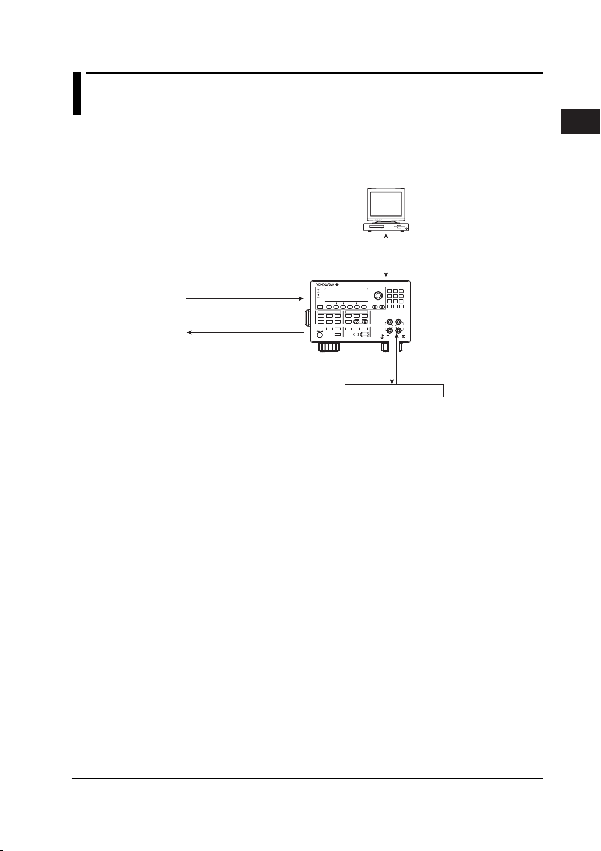
System Configuration
PC
• USB storage (store setup parameters,
recall statistical computation values, and
save/load equations, programs, and panel settings)
• Remote control
Trigger input
Sweep start input
Interlock input
Output ON/OFF (relay)
control input
GS610
Zero source control input
POWER
Trigger output
Source change timing output
Measure start timing output
Measure end timing output
(Voltage or current)
Pulse end timing output
Sweep synchronization output
Sweep 1 turn end timing output
Sweep all end timing output
Interlock through output
Output ON/OFF (relay) status output
Zero source status output
Programmable output
Comparison result output
Comparison end output
USB (USB storage)
Communication
(Ethernet, GP-IB, and RS-232*)
GS610
SOURCE MEASURE UNIT
Source
Measured value
DUT (device under test)
* Conforms to EIA-574.
EIA-574 is an EIA-232 (RS-232) standard
for the 9-pin interface.
2
Explanation of Functions
IM 765501-01E
2-1
2.1 System Configuration and Block Diagram
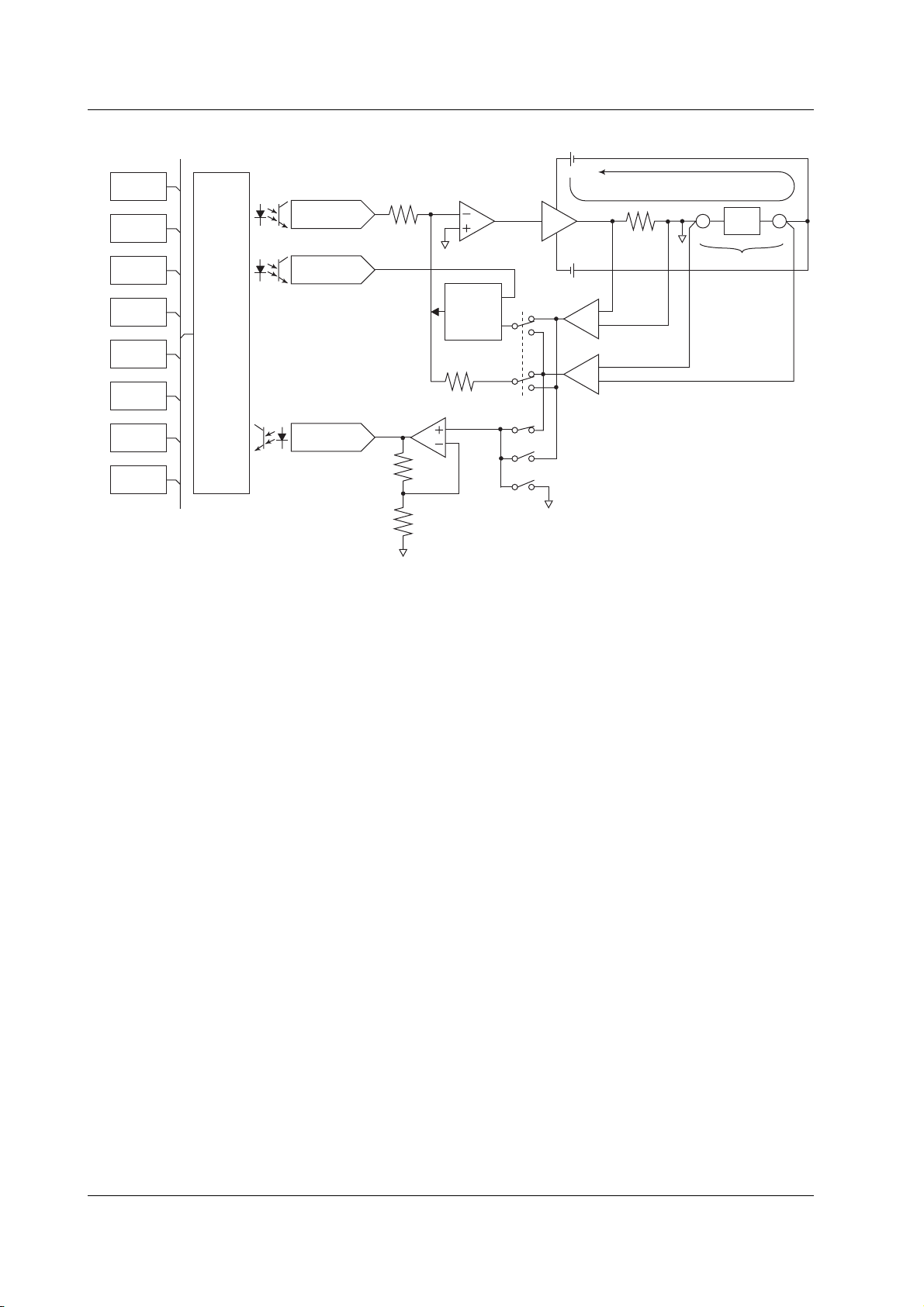
Block Diagram
CPU
VFD
KEY
EXT I/O
RS-232
GP-IB
USB
ETHER
(option)
Analog
control
Io
Source DAC
Limiter DAC
ADC
Limiter
control
circuit
Current sense
amplifier
Voltage sense amplifier
DUT: Device Under Test
DUT
LO HI
Vo
Voltage Vo that appears across output terminals HI and LO is converted to normalized
voltage by a differential amplifier (voltage sense amplifier) that has different gains for
different voltage ranges. In addition, current Io that flows through output terminals HI
and LO is converted to normalized voltage by different shunt resistors and differential
amplifiers (current sense amplifiers) for different current ranges.
The analog section consists of the source block, limiter block, and measurement block.
The source block controls the voltage sense amplifier or the current sense amplifier so
that its output is equal to the source DAC output, and delivers the specified source value
across HI and LO. Two D/A converters are used in the source DAC to achieve a 5.5digit resolution.
The limiter control circuit in the limiter block controls the output across HI and LO so that it is
equal to the specified limiter value when the output from the voltage sense amplifier or
current sense amplifier exceeds the specified limiter value. When generating voltage, the
output from the current sense amplifier is compared with the limiter value; when generating
current, the output from the voltage sense amplifier is compared with the limiter value.
The measurement block measures the output from the voltage sense amplifier or current
sense amplifier. In addition, if the auto zero function is enabled, the internal zero
reference is measured every measurement cycle (measurement operation), and the
offset drift of the measurement pre-amplifier and A/D converter is cancelled while
measurements proceed. A feedback pulse width modulation (an integration type) is
employed for the A/D converter (ADC).
The analog control section transfers data to the D/A converter (DAC), controls various
switches, controls the width measurement of the pulse transferred from the A/D
converter, and so on. To achieve high-speed sweep of 100 µs steps, a high-speed
photocoupler is employed for the transferring of data to the source DAC.
The display employs a 256 × 64 dot VFD
*
to improve the visibility.
The GS610 comes with GP-IB and RS-232 interfaces that provide compatibility with
conventional systems as well as a USB port that is convenient for writing to or reading
data from a PC. An Ethernet port is also provided as an option if you wish to use the
existing network for data communication.
* Vacuum Fluorescent Display
2-2 IM 765501-01E

1
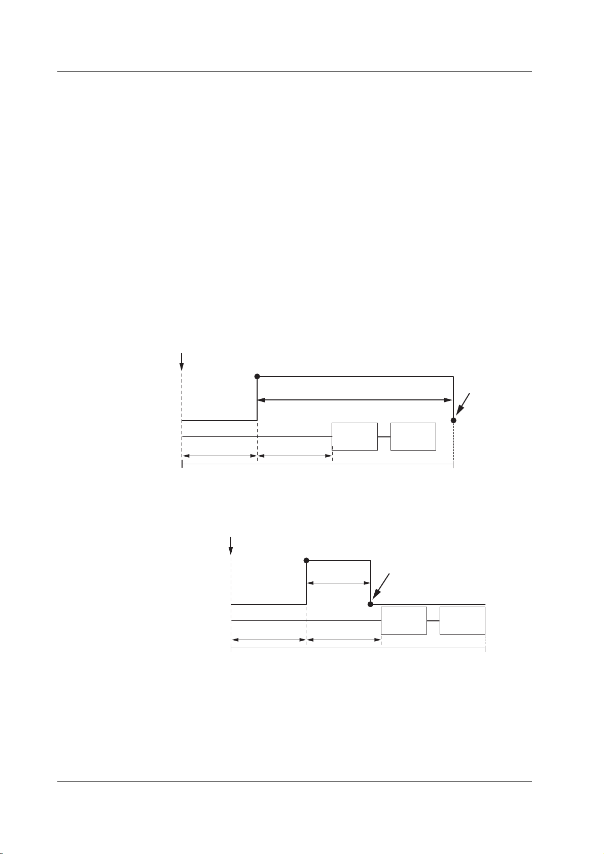
2.2 Source Measure Cycle
Source measure cycle
trigger (see section 2.5, “Triggers”). When the GS610 output is ON, the source measure
cycle is constantly repeated.
In a source measure cycle, the source level changes after a time specified by the source
delay elapses from the point in which the trigger is activated. Furthermore, the
measurement starts after a time specified by the measurement delay elapses. When the
measurement and computation are complete, one source measure cycle is finished.
However, if you change the source level with a key or a communication command in the
middle of a source measure cycle, the source level changes immediately without waiting
for the source delay or measure delay, and the internal trigger phase is reset.
If the measurement function is turned OFF, measure delay, measurement, and
computation are not carried out. The way in which a source measure cycle ends varies
depending on the source mode (see sections 5.4, “DC Source Mode” and 5.5, “Pulse
Source Mode).
Source Measure Cycle Example
(When the Source Mode Is DC and Sweep Mode Is Linear)
Trigger
Source
on the GS610 refers to the basic operation that starts with a
Current source level
Previous source
level
2
Explanation of Functions
Measurement
Source delay
Measurement
delay
Source measure cycle
Measurement
Computation
IM 765501-01E
2-3

2.2 Source Measure Cycle
Flow Chart of a Source Measure Cycle
The time indicated in the chart is a typical time needed for its processing. The averaging
time varies depending on the average count, and the computation time varies depending
on the complexity of the equation.
Tri gg er
Source delay
+S. Delay
Change to optimal range
+2 ms
No
mismatched when auto
source range is
Change source range
Update source level
Is measurement ON?
Measurement delay
A/D operation
Yes
mismatched when auto
measurement range
No
A/D operation
Zero compensation
Range
selected?
+3 ms
+10 µs
+M. Delay
+IntgTime*
Range
is selected?
Auto zero?
+IntgTime*
Yes
No
Yes
No
Yes
Block average
operation?
No
Yes
No
Average count
finished?
Yes
Resistance
measurement?
No
Yes
Calculate resistance
+100 µs
Moving average (+moving
average count × 1.5 µs)
Computation
+150 µs
NULL computation
+20 µs
Comparison
+20 µs
End source
measure cycle
Computation
+150 µs
* Integration time + 200 µs when the integration time is 250 µs, 1 ms, or 4 ms.
Integration time + 520 µs when the integration time is 20 ms, 100 ms, or 200 ms.
2-4 IM 765501-01E
1
2.3 Source
Source Function (See section 5.1 for the procedure)
You can select voltage source (VS) or current source (IS).
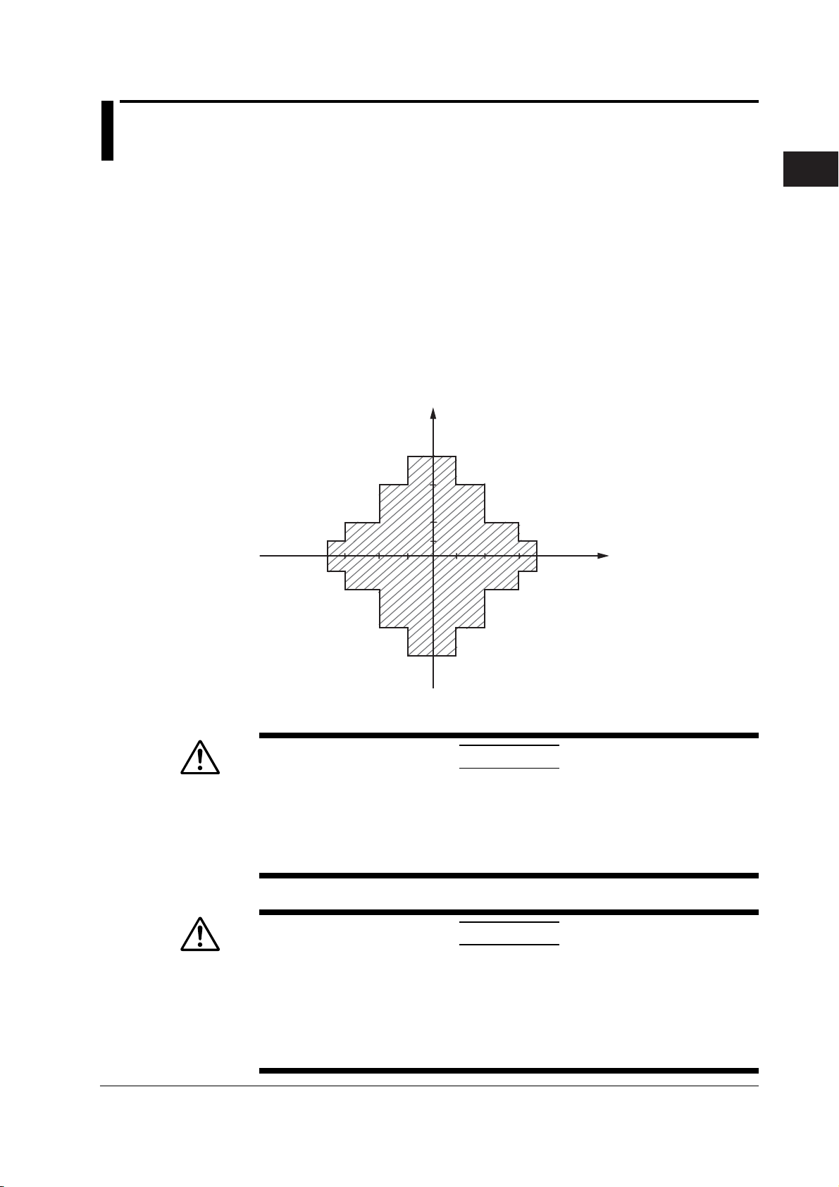
Source Range
The GS610 generates voltage or current in the range specified by the hatched lines in
the figure below. The performance limitations of the GS610 place constraints on the
current and voltage when generating voltage and current, respectively. For example, the
voltage is limited to 30 V or less when 1.5 A is specified when generating current. If the
voltage or current source level is at the boundary of the source range and is limited, a
high limiter indicator (H) illuminates if the level is positive and a low limiter indicator (L)
illuminates if the level is negative.
I
3.2
2
1
0.5
12 30
60
110
V
2
Explanation of Functions
Limiter (See section 5.3 for the procedure)
CAUTION
If a load exceeding the source range above is connected such as a current
source exceeding the current limiter setting when generating voltage or a
voltage source exceeding the voltage limiter setting when generating current,
abnormal load is detected, and the output is turned OFF. Do not connect a load
exceeding the range above to the GS610. Doing so may cause malfunction.
French
ATTENTION
Si vous raccordez une source de courant en mode source de tension dépassant
le paramètre du limiteur de courant, ou une source de tension en mode source
de courant dépassant le paramètre du limiteur de tension, ou encore une charge
dépassant la plage de la source ci-dessus, une charge anormale est détectée et
la sortie est mise hors tension. Ne connectez pas ces types de charge au
GS610, ce dernier risquerait de ne pas fonctionner correctement.
IM 765501-01E
2-5

2.3 Source
If a limiter is set, an additional limit can be placed within the source range. This limit can
prevent damage to the connected device due to overcurrent or overvoltage. The current
limiter is automatically selected when generating voltage, and the voltage limiter is
automatically selected when generating current.
If the limiter is turned OFF, the voltage or current can be generated up to the maximum
value of the source range regardless of the limiter setting.
Voltage Limiter Operation
I
I
Low limiter High limiter
Current Limiter Operation
3.2
0.5
3.2
0.5
2
1
2
1
I
12 30
12 30
60
60
110
110
V
High limiter
V
Low limiter
The high and low limiter values can be set independently. If tracking is turned ON, an
absolute value can be set for the high and low limits, and the limiter functions in the
positive and negative ranges around zero.
If the high limiter is active, the high limiter indicator (H) is shown on the display. If the
low limiter is active, the low limiter indicator (L) is shown on the display.
2-6 IM 765501-01E

1
2.3 Source
Source Range Setting and Auto Range (See section 5.2 for the procedure)
Source Range Setting
The source range settings during voltage generation and current generation are listed below.
• Voltage Source Range Settings
Source Range Setting Source Range Resolution
200 mV ±205.000 mV 1 µV
2 V ±2.05000 V 10 µV
12 V ±12.0000 V 100 µV
20 V ±20.5000 V 100 µV
30 V ±30.000 V 1 mV
60 V ±60.000 V 1 mV
110 V ±110.000 V 1 mV
• Current Source Range Settings
Source Range Setting Source Range Resolution
20 µA ±20.5000 µA 100 pA
200 µA ±205.000 µA1 nA
2 mA ±2.05000 mA 10 nA
20 mA ±20.5000 mA 100 nA
200 mA ±205.000 mA 1 µA
0.5 A ±0.50000 A 10 µA
1 A ±1.00000 A 10 µA
2 A ±2.00000 A 10 µA
3 A ±3.20000 A 10 µA
2
Explanation of Functions
Auto Range
If auto range is turned ON, the range setting with the highest resolution that contains the
source level is automatically selected, eliminating the need for you to manually select the
range setting. However, switching the range setting takes time, and the source level becomes
discontinuous, if the range setting switches as a result of changing the source level.
Source Mode (See sections 5.4 and 5.5 for the procedure)
There are two source modes available.
DC Source Mode
If the sweep mode (see section 2.6, “Sweep”) is ON in DC source mode, the source level
changes after a time specified by the source delay elapses from the point in which the
trigger is activated. Then, measurement starts after a time specified by measurement
delay elapses. When the measurement and computation are complete, one source
measure cycle is finished.
If the sweep mode is OFF, the source level is maintained, and the source measure cycle
is carried out.
If the measurement function (see section 2.4, “Measurement”) is turned OFF, measure
delay, measurement, and computation are not carried out. The source measure cycle is
finished when the source level changes.
Trigger
Current source level
Source
Previous source
level
IM 765501-01E
Measurement
Source delay
Measurement
delay
Source measure cycle
Measurement
Computation
2-7
2.3 Source
Pulse Source Mode
Pulse source mode can be used to improve the reproducibility of measurements on
DUTs that change in characteristics due to the heat generation that results from applying
the source such as a resistor with large temperature coefficient. It is also effective for
evaluation of display devices that use pulse width to control the brightness.
The pulse is specified by two values, the pulse base value and the source level. The
minimum pulse width is 100 µs.
As with the DC source, the source level changes after a time specified by the source
delay elapses from the point in which the trigger is activated. Furthermore, the
measurement starts after a time specified by the measurement delay elapses. The
source level changes at the same the measure delay is activated and returns to the
pulse base value after the pulse width. A source measure cycle is finished at the end of
the pulse or at the end of the measurement and computation, whichever comes later.
If the measurement function (see section 2.4, “Measurement”) is turned OFF, measure
delay, measurement, and computation are not carried out. The end of the pulse is the
end of a source measure cycle.
When the End of the Measurement and Computation Is after the End of the Pulse
Generation
Trigger
Source
Measurement
Current source level
Pulse source end
Base pulse value
Base pulse value
Source delay
Pulse width
Measurement
delay
Source measure cycle
Measurement
Computation
When the End of the Measurement and Computation Is before the End of the Pulse
Generation
Trigger
Current source level
Source
Measurement
Pulse width
Base pulse value Base pulse value
Source delay
Measurement
delay
Source measure cycle
Pulse source end
Measurement
Computation
Source Delay (See section 5.6 for the procedure)
The source delay specifies the wait time at which the source value is actually changed
after the trigger is activated. It is typically used as a trigger delay when an external
trigger is used.
The source delay can be set in the range of 1 µs to 3600 s. However, setting a long
source delay results in a long source measure cycle. Set the smallest value possible.
2-8 IM 765501-01E
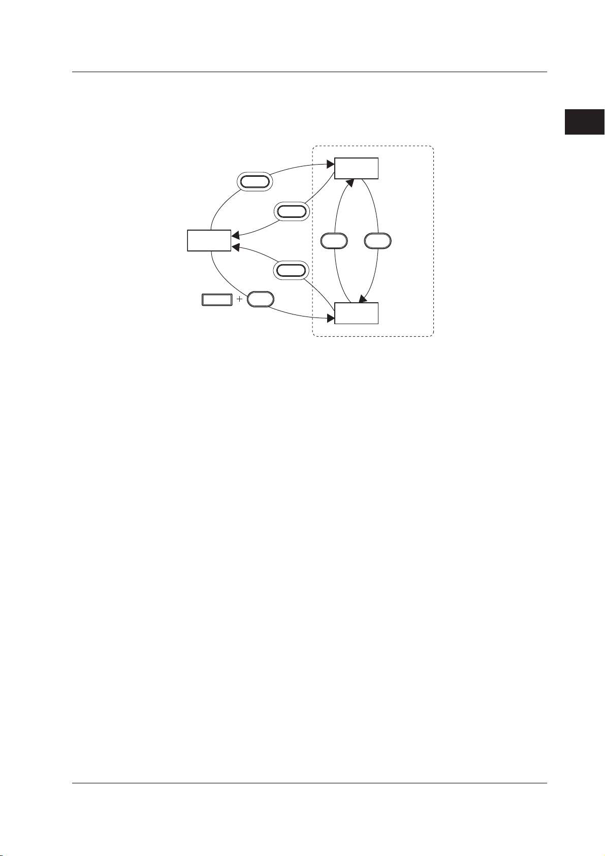
1
Turning the Output ON/OFF and Generating Zero Output
(See sections 5.7 and 5.8 for the procedure)
As shown in the figure below, there are three output modes, Output ON, Output OFF,
and Zero Generation. The mode is switched with the OUTPUT and ZERO keys.
Output
OUTPUT
ON
2.3 Source
2
Explanation of Functions
Output
OFF
SHIFT
OUTPUT
ZERO
OUTPUT
ZERO
Zero
output
OUTPUT
illuminates
ZERO
ZERO
illuminates
Output OFF: The output relay is OFF, and voltage or current is not generated.
The source measure cycle is also stopped.
Output ON: The output relay is ON, and voltage or current is generated. The
source measure cycle is repeated.
Zero Generation: The output relay is ON. If generating voltage, 0 V is generated. If
generating current, 0 A is generated. Then, the source measure
cycle is stopped.
Zero Source Offset
An offset can be specified on the zero value when generating zero output.
Zero Source Impedance
Low impedance (LoZ) is default when generating voltage, and high impedance (HiZ) is
default when generating current. Only the source value is set to zero.
If high impedance is set when generating voltage or low impedance is set when
generating current, the source value is set to zero, and the limiter is constrained to the
minimum value of the range.
Offset Calibration (See section 5.9 for the procedure)
such as due to temperature change. For example, the offset calibration is used to
correct the offset fluctuation due to the leak current of the internal circuit when using a
low current source range in a high temperature environment.
IM 765501-01E
2-9

2.4 Measurement
Turning the Measurement Function ON/OFF (See section 7.1 for the procedure)
If measurement is not necessary, the measurement function can be turned OFF. When
the measurement function is turned OFF, the procedure related to measurement is not
carried out. This enables the source measure cycle to be shortened.
Measurement Function (See section 7.2 for the procedure)
You can select voltage measurement (V), current measurement (I), or resistance
measurement (Ω).
In resistance measurement, current is measured when voltage is generated, and voltage
is measured when current is generated. Then, the resistance is derived by calculating
voltage/current.
Measurement Range Setting and Auto Range (See section 7.3 for the procedure)
The measurement range settings during voltage measurement and current measurement
are listed below. However, the measurement range setting is not directly specified, but
determined indirectly by the source range setting and limiter setting.
• Voltage Measurement Range Settings
Integration Time of 16.66 ms/20 ms, 100 ms, Integration time of 4 ms, 1 ms, or 250 ms
or 200 ms
Range Measurement Resolution Range Measurement Resolution
Setting Range Setting Range
200 mV ±205.000 mV 1 µV 200 mV ±205.00 mV 10 µV
2 V ±2.05000 V 10 µV2 V±2.0500 V 100 µV
20 V ±20.5000 V 100 µV 20 V ±20.500 V 1 mV
110 V ±110.000 V 1 mV 110 V ±110.00 V 10 mV
When Generating Current
Same as the voltage limiter range
When Generating Voltage
Same as the voltage source range
However, if the voltage source range is 12 V, 30 V, or 60 V, the settings below apply.
Voltage Source Range Setting Voltage Measurement Range Setting
12 V 20 V
30 V 110 V
60 V 110 V
• Current Measurement Range Settings
Integration Time of 16.66 ms/20 ms, 100 ms, Integration time of 4 ms, 1 ms, or 250 ms
or 200 ms
Range Measurement Resolution Range Measurement Resolution
Setting Range Setting Range
20 µA ±20.5000 µA 100 pA 20 µA ±20.500 µA1 nA
200 µA ±205.000 µA1 nA 200 µA ±205.00 µA 10 nA
2 mA ±2.05000 mA 10 nA 2 mA ±2.0500 mA 100 nA
20 mA ±20.5000 mA 100 nA 20 mA ±20.500 mA 100 nA
200 mA ±205.000 mA 1 µA 200 mA ±205.00 mA 10 µA
3 A ±3.20000 A 10 µA3 A±3.2000 mA 100 µA
2-10 IM 765501-01E

1
2.4 Measurement
When Generating Voltage
Same as the current limiter range
When Generating Current
Same as the current source range
However, if the current source range is 0.5 A, 1 A, or 2 A, the settings below apply.
Current Source Range Setting Current Measurement Range Setting
0.5 A 3 A
1 A 3 A
2 A 3 A
Auto Range
When auto range is turned ON, the GS610 makes a measurement and checks whether a
different range setting is available for making the measurement with the best resolution.
If there is, the GS610 changes the range setting and makes the measurement again.
However, it may take time for the GS610 to switch the range setting, and the source
level may become discontinuous.
Measurement Delay (See section 7.4 for the procedure)
The measurement delay is the wait time at which the measurement is started after the
source level is switched. It is used for the item being measured to stabilize.
The measurement delay can be set in the range of 1 µs to 3600 s. However, setting a
long measurement delay results in a long source measure cycle. Set the smallest value
possible.
2
Explanation of Functions
Integration Time (See section 7.5 for the procedure)
The integration time is the time that the integrating A/D converter performs integration. If
you increase the integration time, the time needed to make measurements takes longer,
but the measured values are more stable.
When the power frequency is 50 Hz: 250 µs, 1 ms, 4 ms, 20 ms, 100 ms, or 200 ms
When the power frequency is 60 Hz: 250 µs, 1 ms, 4 ms, 16.6 ms, 100 ms, or 200 ms
If the integration time is set to 200 ms, 100 ms, 20 ms, or 16.6 ms, the effects of noise
from the power frequency can be eliminated, because these settings are integer
multiples of the power cycle.
Auto Zero Function (See section 7.6 for the procedure)
When auto zero is ON, the GS610 also measures the internal zero reference for each
measurement. The measured result is obtained by subtracting this value from the
measured value canceling the offset drift of the measurement circuit in the GS610.
However, the measurement takes approximately twice as long, because the GS610
measures twice.
IM 765501-01E
2-11

2.4 Measurement
Auto V/I (See section 7.7 for the procedure)
This function enables the measurement function to be switched when a limiter is
activated.
For example, when a secondary battery is being charged with constant current, the rising
battery voltage can be measured. When the voltage limiter is activated and the
operation switches to constant voltage charge, the reduction in the charging current can
be measured.
When Generating Voltage and Measuring Current
When the limiter is not activated: The GS610 measures current. The voltage source
level is entered for the source value in the result file
when the storage operation is carried out. (Normal
operation)
When the limiter is activated: The GS610 measures voltage. The current limiter
value is entered for the source value in the result file
when the storage operation is carried out.
When Generating Current and Measuring Voltage
When the limiter is not activated: The GS610 measures voltage. The current source
level is entered for the source value in the result file
when the storage operation is carried out. (Normal
operation)
When the limiter is activated: The GS610 measures current. The voltage limiter
value is entered for the source value in the result file
when the storage operation is carried out.
2-12 IM 765501-01E

1
2.5 Triggers
(See section 4.1 for the procedure)
The following three triggers are available for starting a source measure cycle.
Internal trigger (Int): The internal constant period timer is used as triggers. The cycle
can be set in the range of 100 µs to 3600 s.
External trigger (Ext): The rising edge of the voltage signal that is applied to the BNC
input/output terminal or pin 2 on the external input/output
connector on the rear panel is used as a trigger.
Immediate (Imm): The GS610 does not wait for a trigger. When the current source
measure cycle is complete, the next source measure cycle starts
immediately. This trigger can be selected only when the
measurement function is ON.
When the GS610 is waiting for a trigger (when the source measure cycle is complete),
the wait indicator on the display shows “WaitTrigger.” If a trigger is activated, the TRIG
key on the front panel blinks, and WaitTrigger of the wait indicator is turned OFF until the
source measure cycle is complete.
When using an external trigger, manual trigger using the TRIG key on the front panel
and triggers activated with communication commands (“*TRG” or GroupExecuteTrigger)
are valid.
If you wish to activate triggers only with communication commands, select external
trigger and do not apply triggers to the BNC input/output terminal or pin 2 on the external
input/output connector on the rear panel.
2
Explanation of Functions
Note
If another trigger is activated in the middle of a source measure cycle, that trigger is
discarded. If the trigger timing is not synchronized to the source measure cycle period (the
starting point) as in this case, the sampling error indicator (SampleErr) illuminates in the
status display area of the display.
To prevent sampling errors from occurring, increase the interval at which triggers are
activated or shorten the source measure cycle (see section 2.2, “Source Measure Cycle”).
Below are ways of shortening the source measure cycle.
• Set the shortest source delay and measurement delay possible.
• If measurements are not needed, turn the measurement function OFF. When making
measurements, set the shortest integration time possible.
• Turn OFF the auto zero function (see section 2.4, “Measurement”).
• Turn OFF the auto range function of the source and measurement range settings.
• Turn OFF various computation functions.
• When performing a sweep, turn OFF the auto storage function (see section 2.8, “Store/
Recall”).
IM 765501-01E
2-13
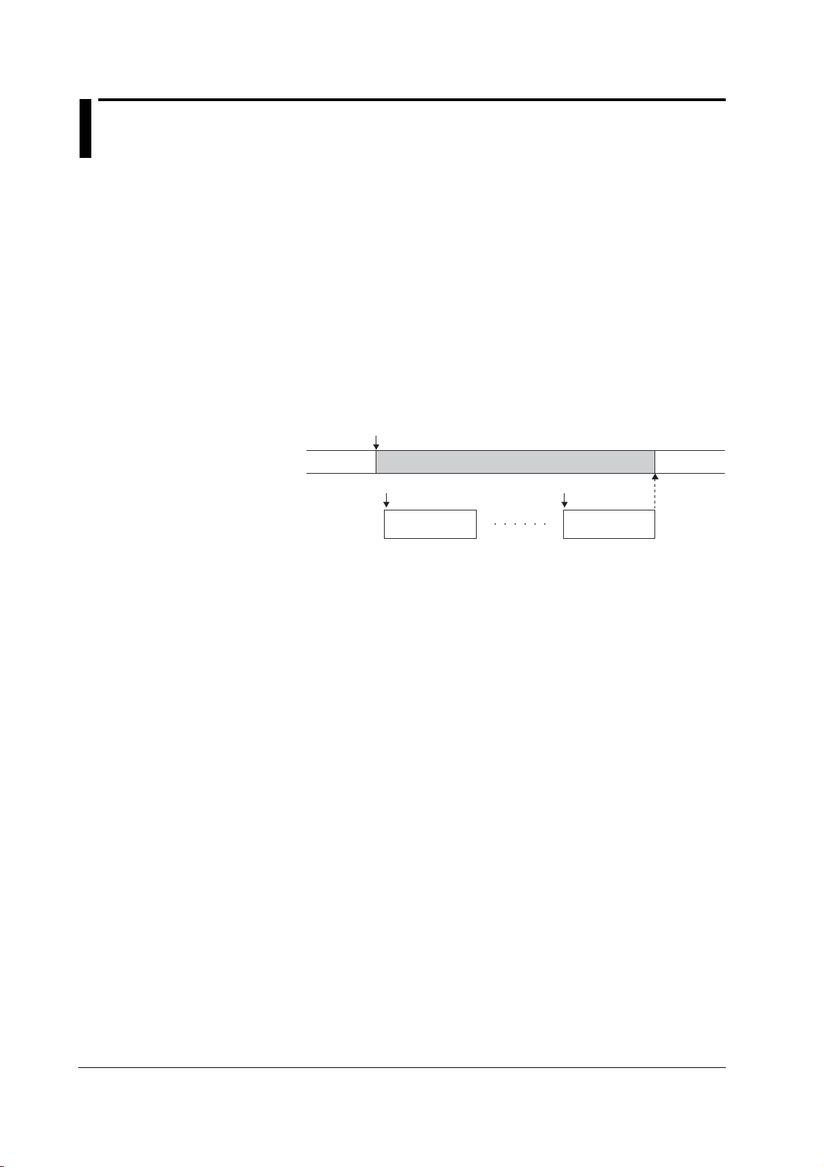
2.6 Sweep
There are three sweep modes, linear sweep, log sweep, and program sweep. To
disable the sweep function, turn it OFF. The sweep key illuminates when the sweep
mode is not OFF.
Basic Sweep Operation
The sweep function repeats the source measure cycle by automatically varying the
source level. In this case, a start event is needed for starting the sweep operation in
addition to the trigger that starts the source measure cycle.
The sweep function starts in a start-wait condition. The GS610 can receive triggers only
after receiving a start event. Once started, the GS610 repeats the source measure cycle
by varying the source level for the subsequent triggers that it receives. When a sweep
operation is completed, the GS610 transits to the start-wait condition again.
Basic Sweep Operation
Start
Sweep state
Waiting for
start
Tri gg er
Source measure
cycle (first)
Sweeping
Tri gg er
Source measure
cycle (last)
Waiting for
start
2-14 IM 765501-01E

1
2.6 Sweep
Sweep Mode (See sections 6.1 and 6.2 for the procedure)
Linear Sweep
Sweeps using evenly spaced step values that increase linearly from the specified start
value to the stop value.
• When the source mode is DC
Source level
Stop value
• When the source mode is pulse
Source level
Step value
Stop value
2
Explanation of Functions
Initial
value
Start value
Start
Step value
Trigger count Trigger count
Initial
value
Start value
Start
Base value
Log Sweep
Sweeps exponentially from the specified start value to the stop value at the specified
step count.
The step count can be set arbitrary in the range of 2 to 65535. However, if the start
value and stop value have opposite signs, an error occurs, and the sweep operation
cannot be carried out.
• When the source mode is DC
Source level
Initial
value
Start value
Start
Stop value
Tri gg er count
Step count
• When the source mode is pulse
Source level
Start value
Initial
value
Start
Tri gg er count
Stop value
Step count
Base value
Program Sweep
Sweeps according to the values in a pattern file containing an arbitrary sweep pattern.
Program Sweep Example
IM 765501-01E
• When the source mode is DC
Source level
Initial
value
Start
Tri gg er count
• When the source mode is pulse
Source level
Initial
value
Start
Trigger count
Base value
2-15

2.6 Sweep
Termination Mode (See section 6.3 for the procedure)
There are two termination modes, Keep and return (Rtn).
In Keep mode, the last source level of the sweep operation is retained. In Return (Rtn)
mode, the source level after the sweep operation is complete is reset to the level before
the sweep operation was started.
• Sweep operation when the termination mode (Last) is set to keep
Start
Sweep state
Source measure
cycle
Source level
Waiting for
start
Stop value
Start value
Source level
before sweep
Trigger
Sd
Sweeping
Trigger Trigger Trigger Trigger
Meas
Meas Sd Meas Sd Meas Sd Meas
Sd
Sd: Source delay
Meas: Measurement delay + measurement + computation
Waiting for
• Sweep operation when the termination mode (Last) is set to return (Rtn)
Start
Sweep state
Source measure
cycle
Source level
Waiting for
start
Stop value
Start value
Trigger
Sd
Sweeping
Trigger Trigger Tr igger Trigger
Meas
Sd Meas Sd
Meas
Sd Meas Sd Meas
Trigger
Waiting for
Sd
start
start
Source level
before sweep
Sd: Source delay
Meas: Measurement delay + measurement + computation
Repeat Count (See section 6.4 for the procedure)
The selectable range is 1 to 1000 or infinity (∞). For example, if the repeat count is set
to 5, the GS610 repeats the sweep operation five times when it receives a start event.
Then, the GS610 returns to the start-wait condition. If infinity (∞) is selected, the GS610
starts the sweep operation when it receives a start event and repeats the operation until
the sweep operation or output is turned OFF.
2-16 IM 765501-01E

1
2.7 Computation
Averaging (See section 8.1 for the procedure)
When the averaging function is used, the specified number (average count) of measured
values are averaged to derive the final displayed value. Therefore, the measured results
are more stable.
There are two averaging modes, block average and moving average.
Block average: The specified average count of measurements is carried out in a single
source measure cycle. The GS610 displays the result obtained by
summing the measured values and dividing the sum value by the
average count. Therefore, the measurement time takes average count
times as long.
Moving average: The GS610 measures once in a single source measure cycle. The
GS610 displays the result obtained by summing the average count of
measured values and dividing the sum value by the average count. If
the number of measurements does not reach the average count, the
average over the number of measurements is displayed.
Display value =
The average count can be set in the range of 2 to 256.
When the averaging function is enabled, the average indicator on the left side of the
GS610 illuminates.
1
AVerageCount
AVerageCount
× Measured value [i]
Σ
i=1
NULL Computation (See section 8.2 for the procedure)
In NULL computation, a difference with respect to a given value can be displayed. The
NULL value is set to the measured value when the NULL computation is turned ON.
From that point, the GS610 displays the results obtained by subtracting the NULL value
from the measured values.
2
Explanation of Functions
Displayed value = Measured value – NULL value
When the NULL computation is switched from OFF to ON, the measured value at that
point is automatically entered as the NULL value. However, this value can be changed
afterwards.
When the NULL computation is enabled, the NULL key illuminates.
Computation Using Equations (See section 8.3 for the procedure)
Computation can be performed using equations provided in a text file. In computation
using equations, four arithmetic operations, trigonometric functions, and so forth can be
performed on variables such as source values and measured values as well as
constants.
For example, if an equation “m=I*V” is applied, the GS610 calculates and displays the
power.
The equation can be selected from the definition files in the MATH directory on the
internal GS610 ROM disk (see section 2.9, “USB Storage Function). For the definitions
files, you can use built-in computation files that are available when the GS610 is shipped
from the factory (or when the disk is formatted (see section 4.3, “USB Storage Function”)
and user-defined computation files that you create such as on a PC.
If the definition file contains an equation with variables A, B, and C, the values for A, B,
and C can be entered from the GS610 panel soft keys. Computation using equations
can be used not only to perform computation using measured values, but also to create
the next source value from the calculation.
IM 765501-01E
2-17

2.7 Computation
The following five equations are available as built-in computation.
• Decibel (dB.txt)
m=A*log(m/B): Computes the decibel of the measured value with respect to B.
• Percent (Percent.txt)
m=(m/A)*100: Computes the percentage of the measured value with respect to A.
• Scaling (Scaling.txt)
m = A*M+B: Scales the measured value.
• Power (Power.txt)
m=V*I: Calculates the power from the source value and measured value. However, if
the source and measurement are of the same function or when measuring resistance,
the power cannot be calculated correctly. To measure power, set the GS610 to
voltage generation and current measurement or current generation and voltage
measurement.
• Sinusoid generation (Sinusoid.txt)
s=A*sin(2*PI*B*t): Generates a sinusoid of amplitude A and frequency B. However, if
the sweep function is enabled, the sweep operation takes precedence. To generate
the sinusoid, turn the sweep function OFF.
When computation using equations is turned ON, the MATH key illuminates. For details
on the syntax and operators of equations in the definition files, see appendix 1.
Comparison Operation (See section 8.4 for the procedure)
The measured value is compared with the upper and lower limits specified by the user
and divided into three groups, over the upper limit (High), within the limits (In), and under
the lower limit (Low). The result of the grouping is displayed at the upper left corner of
the status display area on the display and output to the external input/output connector.
For a description of the external input/output, see section 10.1, “Setting the Input/Output
Signal on the BNC Input/Output Terminal and External Input/Output Connector.”
When the comparison operation is turned ON, the MATH key illuminates.
2-18 IM 765501-01E

1
2.8 Store and Recall (Statistical Computation Value Display)
Storage Operation (See section 9.1 for the procedure)
This function stores up to 65535 points of the results of the source measure cycle in the
store memory. The contents of the store memory is output to the internal GS610RAM as
a result file (Result.csv) after the storage operation is complete. The contents output to
the result file are arrays of elapsed times from the store start point, source values,
measured values, and setting changes during the sweep operation.
When you press the STORE key, the storage operation starts and the STORE key
illuminates. Then, when the store count of source measure cycles is complete, the
storage operation automatically ends, and the result file (Result.csv) is created.
If you press the STORE key while the storage operation is in progress, the storage
operation is stopped, and the contents stored up to that point is saved to the result file
(Result.csv).
The store count can be set in the range of 1 to 65535.
Auto Storage (See section 9.1 for the procedure)
The auto storage function automatically starts the storage operation with the start of the
sweep operation. The store count in this case is automatically set to the sweep repeat
count. However, if the sweep repeat count exceeds 65535, the store count is set to
65535.
2
Explanation of Functions
Recall (See section 9.2 for the procedure)
When you carry out a recall operation, the statistical computation results of the
measured values in the store memory can be retrieved. The statistical computation
parameters are the store count, minimum value, maximum value, maximum value –
minimum value, average value, and standard deviation.
IM 765501-01E
2-19

2.9 USB Storage Function
The GS610 has a built-in 4-MB non-volatile disk (GS610ROM) and a 4-MB volatile disk
(GS610RAM). If the GS610 is connected to a PC with a USB cable, these disks can be
accessed from the PC as removable disks.
Non-Volatile Disk (GS610ROM)
GS610ROM is a non-volatile disk that retains the data on the disk even when the power
is turned OFF. It contains three directories, MATH, PROGRAM, and SETUP. Equation
definition files, program sweep files, and so forth can be stored on this disk to be used on
the GS610.
MATH
A directory for storing the definition files of equations.
The files in this directory can be selected for the computation using equations.
By factory default, built-in computation files are stored in this directory.
The built-in computation files are not erased even if the disk is formatted.
2-20 IM 765501-01E

1
PROGRAM
A directory for storing the pattern files of program sweeps.
The files in this directory can be selected for the program sweep function.
By factory default, sample program files are stored in this directory.
The sample program files are not erased even if the disk is formatted.
SETUP
A directory for storing the GS610 panel settings.
The files in this directory can be selected as setup files.
By factory default, a default setup file is stored in this directory.
The default setup file is not erased even if the disk is formatted.
Volatile Disk (GS610RAM)
GS610RAM is a RAM disk that is automatically formatted when the power is turned ON.
When the storage operation is carried out, the result file (Result.csv) file is created on
this disk. If the settings are saved to the GS610RAM, the current settings are saved to a
file named Setup.txt.
This directory is usually used to pass files that the GS610 creates to the PC. However,
this disk is also used to write the system file (System.bin) from a PC when updating the
system firmware. For details, see section 17.5, “Updating the System Firmware.”
2.9 USB Storage Function
2
Explanation of Functions
You can also create subdirectories and write files to this disk, but be sure that the disk
does not become full. The data on this disk is lost when the power is turned OFF.
Formatting the Disk (See section 4.3 for the procedure)
You can format the disk when you wish to reset the GS610 to factory default conditions,
when the non-volatile or volatile disk cannot be detected on your PC, or if you believe the
data on the disk is corrupt.
IM 765501-01E
2-21

2.10 Other Functions
Sensing (See section 4.2 for the procedure)
The GS610 has two types of sensing connections, 2W (two-terminal connection = local
sense) and 4W (four-terminal connection = remote sense). You can select the
appropriate sensing connection according to the amplitude of the output current.
Four-terminal connection reduces the effects of the voltage drop due to the output
current and lead resistance.
BNC Input/Output and External Input/Output (See chapter 10 for the procedure)
The GS610 has a BNC terminal (TRIG/SWEEP/CTRL IN/OUT) and external input/output
connector (EXT I/O) that can be used to input or output trigger signals and other signals
and output the comparison results.
GP-IB/RS-232 Communication (See chapters 13, 14 for the procedure)
The GS610 is equipped with a GP-IB interface and RS-232 interface that can be used to
control the GS610 using commands.
On the RS-232 interface, various parameters such as baud rate (9600 bps to 115200
bps), flow control (none, XON-OFF, or CTS-RTS), and terminator (CR, LF, or CR+LF).
The command control using the GP-IB, RS-232, and the optional Ethernet interface are
mutually independent, and can be used simultaneously. For example, the GS610 can be
controlled via the GP-IB interface while monitoring the status via the Ethernet interface.
Ethernet Communications (Option) (See chapter 12 for the procedure)
A LAN interface with auto switching between 10 Mbps and 100 Mbps.
In addition to controlling the GS610 using commands, up to five FTP clients can be
connected through the anonymous FTP server function. The non-volatile disk
(GS610ROM) and volatile disk (GS610RAM) are available as subdirectories at the FTP
root. Files can be transferred freely using the FTP protocol.
You can set a fixed address for the IP address or obtain the address dynamically from
the DHCP server.
Command control server function: A command mnemonic stream parsing server at port
7655 that allows up to five clients to connect.
The terminator (CR, LF, or CR+LF) can be specified.
FTP server function: An anonymous FTP server at port 21 that allows up
to five clients to connect.
HTTP server function: A function that enables various information to be
displayed and performs remote control of the GS610
through port 80 using a Web browser.
Each server function is independent. Therefore, for example, the GS610 can be
controlled using commands while transferring files using FTP.
Saving/Loading Setup Data (See sections 11.1 and 11.2 for the procedure)
The current settings can be saved to a setup file (Setup1.txt to Setup4.txt) on the nonvolatile disk (GS610ROM). The saved setup data can be loaded to restore the settings.
The setup data can also be saved to the volatile disk (GS610RAM). This feature can be
used to pass the setup file (Setup.txt) to a PC.
The setup file is a text file containing communication commands. The file can be edited
later on a PC.
2-22 IM 765501-01E

1
2.10 Other Functions
Setting at Power ON (See section 11.3 for the procedure)
The GS610 settings at power on can be changed from the default settings to the settings
selected by the user. If one of the saved setup files is selected as the settings at power
on, the GS610 starts up using the specified settings from the next time the GS610 is
powered ON.
If the selected file is deleted or renamed, the GS610 starts up with default settings.
Turing ON/OFF the Beep Sound (See section 11.4 for the procedure)
You can select whether the GS610 generates a beep sound when you operate the
GS610 incorrectly, when an error occurs during operation, or when the computation is
turned ON.
Error Log Display (See section 11.5 for the procedure)
The GS610 stores up to 127 runtime errors and command errors in the error memory. If
one or more errors exist in the error memory, the error indicator (Err) at the upper right of
the screen illuminates.
Setting the Display Brightness or Turning OFF the Display
(See section 11.6 for the procedure)
You can set the brightness of the display. You can turn OFF the display to prolong the
service life of the display.
2
Explanation of Functions
Key Lock (See section 11.7 for the procedure)
You can lock the panel keys so that the settings are not changed inadvertently.
Selecting the Decimal Point and Separator Notations of CSV Files
(See section 11.8 for the procedure)
You can select the decimal point (period or comma) and the separator (comma or
semicolon) notations according to the Excel program that you use. The selected
notation is applied to program pattern files and measurement result files in CSV format.
Self Test (See section 17.3 for the procedure)
You can test the display and keys.
Checking the System Status (See section 17.4 for the procedure)
The GS610 displays the product name, serial number, firmware version, options, and
calibration date.
Updating the System Firmware (See section 17.5 for the procedure)
The GS610 system can be updated by storing the most recent system file from a PC to
the volatile disk (GS610RAM).
IM 765501-01E
2-23

3
2
1
Chapter 3 Instrument Preparation and Common Operations
3.1 Handling Precautions
Read the Safety Precautions
Safety Precautions
If you are using this instrument for the first time, make sure to thoroughly read “Safety
Precautions” given on pages vi and viii.
Do Not Remove the Case
Do not remove the case from the instrument. Some sections inside the instrument have
high voltages that are extremely dangerous. For internal inspection and adjustment,
contact your nearest YOKOGAWA dealer.
Unplug If Abnormal Behavior Occurs
If you notice smoke or unusual odors coming from the instrument, immediately turn OFF
the power and unplug the power cord. If these symptoms occur, contact your nearest
YOKOGAWA dealer.
Correct the Problem If Output Is Forcibly Turned OFF
If the GS610 detects an internal circuit error due to an excessive external input or
oscillation in the GS610, the GS610 forcibly turns OFF the output and displays an error.
If this happens, remove the cause of the problem such as the load connected externally,
and turn the output ON again. If the output still turns OFF after correcting the problem,
the GS610 may have malfunctioned. Contact your nearest YOKOGAWA dealer. Note
that the error display remains until you manually clear it (see section 11.5, “Error Log
Display”) or read the error information via communications even if the GS610 recovers.
3
Instrument Preparation and Common Operations
Turn the Power Switch OFF If Overheat Is Detected
If the GS610 detects an overheat condition such as when the inlet or vent holes for the
cooling fan are obstructed or the fan is stopped, the GS610 forcibly turns the output OFF
and displays a “Temperature Abnormality” warning. If this happens, immediately turn
OFF the power switch. Provide adequate space around the GS610 or check and
remove foreign objects caught in the cooling fan on the rear panel. If the same warning
appears after waiting a substantial amount of time and you turn ON the power switch, the
GS610 may have malfunctioned. Contact your nearest YOKOGAWA dealer.
Do Not Damage the Power Cord
Nothing should be placed on top of the power cord. The power cord should also be kept
away from any heat sources. When unplugging the power cord from the outlet, never pull
by the cord itself. Always hold and pull by the plug. If the power cord is damaged, check
the part number indicated on page iii and purchase a replacement.
Turn the Power Switch OFF If Overload Is Detected
If the internal power supply is overloaded due to an excessive external input or internal
oscillation, the GS610 forcibly turns the output OFF and displays a “Circuit Protection”
warning. If this happens, immediately turn OFF the power switch. If the same warning
appears when you turn ON the power switch after removing the cause of the problem
such as the load connected externally, the GS610 may have malfunctioned. Contact
your nearest YOKOGAWA dealer.
IM 765501-01E
3-1

3.1 Handling Precautions
General Handling Precautions
Do Not Place Objects on Top of the Instrument
Never place objects containing water on top of the instrument, otherwise a breakdown
may occur.
Do Not Apply Shock or Vibration
Do not apply shock or vibration. Doing so may cause malfunction. In addition, applying
shock to the input/output terminal or the connected cable can cause electrical noise to
enter or output from the instrument.
Keep Electrically Charged Objects Away from the Instrument
Keep electrically charged objects away from the input connectors. They may damage the
internal circuitry.
Turn OFF the Power during Periods of Extended Non-Use
Turn OFF the power switch and remove the power cord from the outlet.
Carry the Instrument Properly
Remove the power cord and connecting cables. The instrument weighs approximately
7 kg. To carry the instrument, use the handle as shown in the figure below, and move it
carefully.
POWER
REGALL
MENU
STORE
MISC
LOCAL
COMPARE
DISPLAY
ESC
MATH
MEASURE
SHIFT
KEY LOCK
RANGE
REMOTE
AUTO
KEY LOCK
TIME
4 WIRE
VALUE
AVERAGE
NULL
MEASURE
V
I
SWEEP
RANGE
OUTPUT CONTROL
AUTO
ZERO
MODE
START
OUTPUT
MENU
SOURCE
LIMIT
MODE
RANGE
TRIG
SOURCE
VSIS
MAX
250V
MAX
110V
BS
Lo
SENSE
MAX
1V
Hi
0
OUTPUT
MAX
1
110V
4
.
7
2
5
+
-
8
3
6
9
Cleaning
When wiping off dirt from the case or operation panel, turn OFF the power switch and
remove the power cord from the outlet. Then, gently wipe with a soft dry clean cloth. Do
not use volatile chemicals since this might cause discoloring and deformation.
3-2 IM 765501-01E

3
2
1
3.2 Installing the GS610
• This instrument is designed to be used indoors. Do not install or use it outdoors.
• Install the instrument so that you can immediately remove the power cord if an
abnormal or dangerous condition occurs.
If you block the inlet or outlet holes on the GS610, the GS610 will become hot
and maybreak down.
French
• L’instrument est prévu pour une utilisation en intérieur. Ne pas l’installer, ni
l’utiliser à l’extérieur.
• Installer l’instrument de manière à pourvoir immédiatement le débrancher du
secteur en cas de fonctionnement anormal ou dangereux.
WARNING
3
Instrument Preparation and Common Operations
CAUTION
AVERTISSEMENT
ATTENTION
Ne pas boucher les orifices d’entrée ou de sortie du GS610 pour éviter toute
surchauffe et panne éventuelle.
IM 765501-01E
3-3

3.2 Installing the GS610
Installation Position
WARNING
To prevent fire, never use the instrument with the rear side facing down. There
are inlet holes for the cooling fan on the rear panel. Placing the instrument with
the rear side down can cause a fire when the instrument malfunctions. If you
must use the instrument with the rear panel down, place a metal plate or a
flame-resistive barrier (grade UL94V-1 or higher) beneath the instrument.
French
AVERTISSEMENT
Pour éviter tout incendie, n’utilisez jamais l’instrument lorsque le panneau
arrière est orienté vers le bas. En effet, le panneau arrière comprend des
orifices destinés au ventilateur de refroidissement. S’il est orienté vers le bas, un
incendie risque de survenir en cas de dysfonctionnement de l’instrument. Si
vous devez utiliser l’instrument lorsque le panneau arrière est orienté vers le
bas, interposez une plaque en métal ou une barrière résistante aux flammes
(grade UL94V-1 ou plus) sous l’instrument.
Place the instrument in a horizontal position or inclined position using the stand as
shown in the center of the figure below.
When using the stand, pull it forward until it locks (perpendicular to the bottom surface of
the instrument). If you are installing the instrument on a slippery surface, attach the
rubber feet (two pieces, included in the package) to the feet.
If you are not using the stand, return it to the original position while pressing the leg
section of the stand inward.
3-4 IM 765501-01E

3
2
1
Installation Conditions
Install the instrument in a place that meets the following conditions.
Ambient Temperature and Humidity
Use the instrument in the following environment:
• Ambient temperature: 5 to 40°C
However, in order to obtain highly accurate measurements, operate the instrument in
the 23 ± 5°C temperature range.
• Ambient humidity: 20 to 80%RH
No condensation should be present. However, in order to obtain highly accurate
measurements, operate the instrument in the 50 ± 10% RH range.
Note
Flat and Even Location
Place the instrument on a flat, even surface. Do not place the instrument on an unstable
or sloped surface.
3.2 Installing the GS610
3
Instrument Preparation and Common Operations
Condensation may occur if the recorder is moved to another place where both the ambient
temperature and humidity are higher, or if the temperature changes rapidly. If this happens,
let the recorder adjust to the new environment for at least one hour before using it. If you
transport the instrument in its packing box, to prevent condensation, allow it to adjust to the
new ambient temperature for at least an hour before taking it out of the box.
Well-Ventilated Location
Inlet holes are located on the top and sides of the instrument. In addition, there are vent
holes for the cooling fan on the rear panel. To prevent internal overheating, allow for
enough space around the instrument (see the figure below) and do not block the inlet
and vent holes.
10 cm or more
AVERAGE
4 WIRE
KEY LOCK
REMOTE
DISPLAY
ESC
MEASURE
SOURCE
AUTO
I
V
VS IS
LIMIT
MODE
STORE
RANGE
MENU
MEASURE
MENU
SOURCE
RANGE
AUTO
NULL
REGALL
MATH
RANGE
VALUE
COMPARE
OUTPUT CONTROL
LOCAL
SWEEP
START
TRIG
TIME
MISC
POWER
A
V
E
R
A
G
E
4 WIRE
KEY LOCK
REMOTE
DIS
P
LAY
ESC
MEASURE
STORE
MENU
AUTO
R
A
NG
REGA
E
LL
V
I
MEASURE
MATH
COMP
POWER
ARE
L
O
C
AL
MIS
C
7
S
OURCE
8
MO
NUL
DE
L
4
VA
LU
E
T
I
ME
KEY LO
C
K
S
HI
F
T
9
LIMIT
5
AUTO
RANGE
M
ENU
1
6
VS
IS
R
ANG
S
2
OUR
E
CE
OUTPUT C
0
3
SWE
EP
.
O
NTRO
+
START
-
L
SENSE
TRIG
ZE
MO
R
D
O
E
OUTPUT
OUTP
110V
H
i
UT
MA
X
1V
MAX
2
50V
110V
M
A
M
X
A
X
Lo
Secure adequate space around the GS610
so that the operation of the power switch
is not obstructed.
MODE
KEY LOCK
ZERO
OUTPUT
SHIFT
5 cm or more5 cm or more
789
456
123
BS
.
+
-
0
OUTPUT
SENSE
Hi
110V
1V
110V
MAX
MAX
MAX
Lo
250V
MAX
10 cm or
more
Do not install the instrument in the following places.
• Outdoor
• In direct sunlight or near heat sources.
• Where the instrument is exposed to water or other liquids.
• Where an excessive amount of soot, steam, dust, or corrosive gas is present.
• Near strong magnetic field sources.
• Near high voltage equipment or power lines.
• Where the level of mechanical vibration is high.
• On an unstable surface.
IM 765501-01E
3-5

3.2 Installing the GS610
Storage Location
Rack Mount
When storing the instrument, avoid the following places:
•A place with a relative humidity of 80% or more.
• In direct sunlight.
• Where the temperature is 60°C or higher.
• Near a high humidity or heat source.
• Where the level of mechanical vibration is high.
• Where corrosive or explosive gas is present.
• Where an excessive amount of soot, dust, salt, and iron are present.
• Where water, oil, or chemicals may splash.
It is recommended that the instrument be stored in an environment where the
temperature is between 5 and 40°C and the relative humidity is between 20 and 80%
RH.
When rack mounting the GS610, use the rack mount kit that is sold separately. For the
procedure on attaching the GS610 to a rack, see the User’s Manual included in the rack
mount kit.
Name Model Notes
Rack mount kit 751533-E3 For EIA single mount
Rack mount kit 751534-E3 For EIA dual mount
Rack mount kit 751533-J3 For JIS single mount
Rack mount kit 751534-J3 For JIS dual mount
3-6 IM 765501-01E

3
2
1
3.3 Connecting to the Power Supply
Before Connecting the Power
To prevent the possibility of electric shock and damage to the instrument, follow the
warnings below.
WARNING
• Before connecting the power cord, ensure that the source voltage matches the
rated supply voltage of the instrument and that it is within the maximum rated
voltage of the provided power cord.
• Connect the power cord after checking that the power switch of the instrument is
turned OFF.
• To prevent electric shock or fire, be sure to use the power cord for the
instrument that was supplied by YOKOGAWA.
• Make sure to perform protective earth grounding to prevent electric shock.
Connect the power cord to a three-prong power outlet with a protective earth
terminal.
• Do not use an extension cord without protective earth ground. Otherwise, the
protection function will be compromised.
• Use an AC outlet that complies with the power cord provided and securely
connect the protective grounding. If such an AC outlet is unavailable and
protective grounding cannot be furnished, do not use the instrument.
3
Instrument Preparation and Common Operations
French
AVERTISSEMENT
• Avant de brancher le cordon d’alimentation, vérifier que la tension source
correspond à la tension d’alimentation nominale de l’instrument et qu’elle est
compatible avec la tension nominale maximale du cordon d’alimentation.
• Brancher le cordon d’alimentation après avoir vérifié que l’interrupteur
d’alimentation de l'instrument est sur OFF.
• Pour éviter tout risque de choc électrique ou d’incendie, utiliser exclusivement le
cordon d’alimentation fourni par YOKOGAWA et prévu pour l’instrument.
• Relier l’instrument à la terre pour éviter tout risque de choc électrique. Brancher
le cordon d’alimentation sur une prise de courant à trois plots reliée à la terre.
• Toujours utiliser une rallonge avec broche de mise à la terre, à défaut de quoi
l’instrument ne serait pas relié à la terre.
• En l’absence de prise secteur conforme au cordon d’alimentation et dans
l’impossibilité de mettre l’instrument à la terre, ne pas utiliser l’instrument.
IM 765501-01E
3-7

3.3 Connecting to the Power Supply
Connecting the Power Cord
1. Check that the power switch is OFF.
2. Connect the power cord plug to the power connector on the rear panel. (Use
3. Connect the plug on the other end of the power cord to the outlet that meets the
Item Specifications
Rated supply voltage 100 to 120 VAC, 220 to 240 VAC
Permitted supply voltage range 90 to 132 VAC, 198 to 264 VAC
Rated power supply frequency 50/60 Hz
Permitted supply voltage frequency range 48 to 63 Hz
Maximum power consumption Approx. 200 VA
* The instrument can use a 100-V or a 200-V system for the power supply. Check that the
voltage supplied to the instrument is less than or equal to the maximum rated voltage of the
provided power cord (see page iv) before using it.
the power cord that comes with the package.)
conditions below. The AC outlet must be of a three-prong type with a protective
earth ground terminal.
USB
100 - 120V
200VA MAX
220 - 240V AC
50
60Hz
EXT I
O
3-prong outlet
Power cord
(standard accessory)
3-8 IM 765501-01E
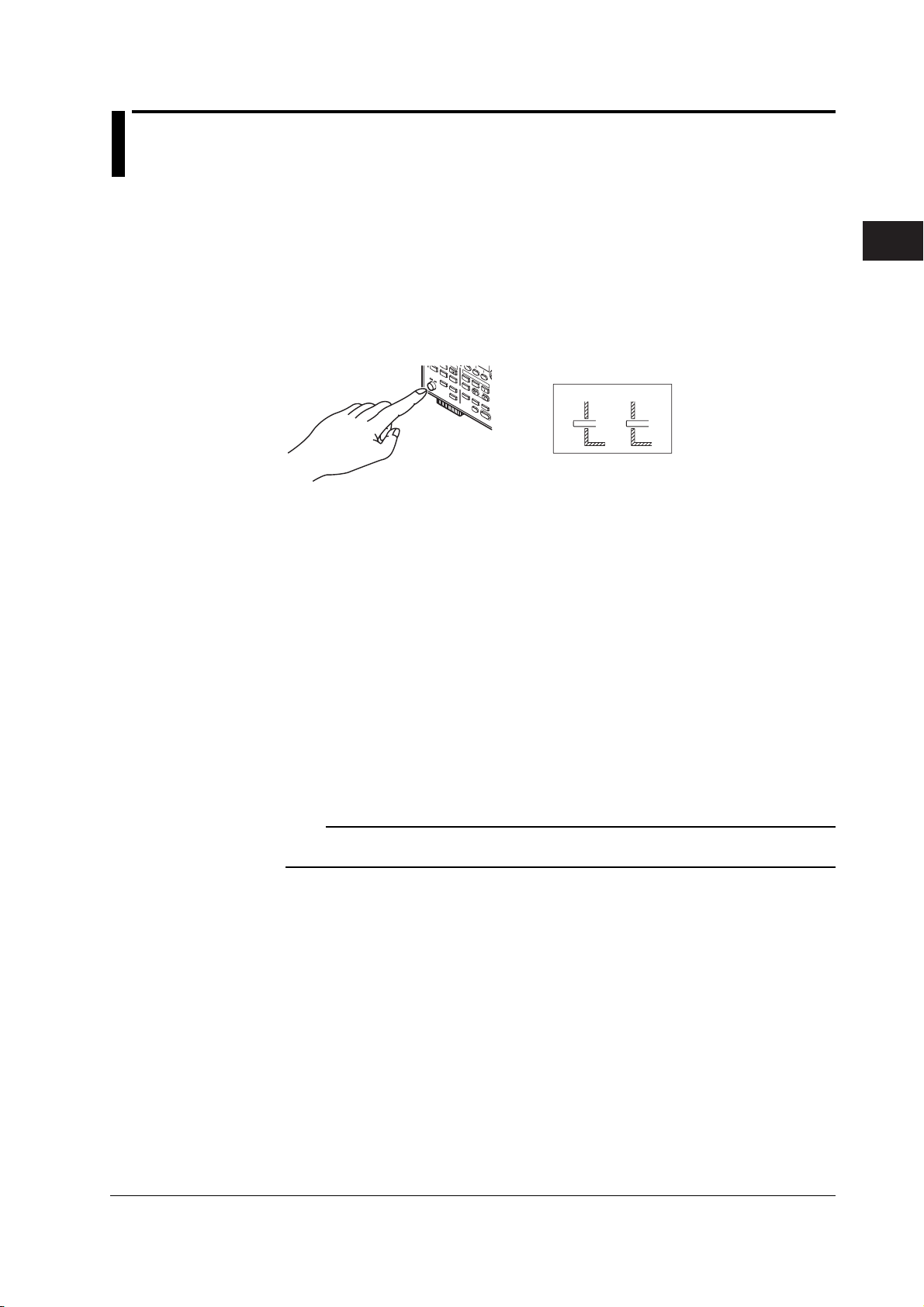
3
2
1
3.4 Turning the Power Switch ON/OFF
Items to Be Checked before Turning ON the Power
• Check that the instrument is installed properly (see section 3.2, “Installation”).
• Check that the power cord is connected properly (see section 3.3, “Connecting the
Power Supply”).
Location of the Power Switch and ON/OFF Operation
The power switch is located in the lower left corner of the front panel. The power switch
is a push button. Press the button once to turn it “ON” and press it again to turn it “OFF.”
AUTO
RANGE
REGALL
V
I
MEASURE
MATH
COMPAR
POWER
SOURCE
E
MODE
NULL
LOCAL
VALUE
MISC
LIMIT
AUTO
MENU
RANGE
TIME
VS IS
KEY
RANGE
L
SOURCE
OCK
Power ON Operation
When the power switch is turned ON, the self-test starts automatically. When the selftest completes successfully, the GS610 is set to the factory default settings or the
settings corresponding to the setup data file you specified in advance (see section 11.3,
“Selecting the Power ON Setting”).
SHIFT
OUTPUT CONTROL
SWEEP
START
ZERO
TRIG
MODE
OUTPUT
OFF ON
3
Instrument Preparation and Common Operations
If the Instrument Does Not Start Normary When the Power Is Turned On
If the GS610 does not operate as described above when the power switch is turned ON,
turn OFF the power switch and check the following points:
• Check that the power cord is securely connected.
• Check that the voltage supplied from the power outlet is correct. See section 3.3.
• You can initialize the settings of the GS610. See section 11.2.
If the GS610 still fails to power up when the power switch is turned ON after checking
these points, it is probably a malfunction. Contact your nearest YOKOGAWA dealer for
repairs.
Note
If you are turning the power switch ON after turning it OFF, allow at least 5 s before turning it
ON.
For Making Accurate Measurements
At the installation location indicated in section 3.2, allow the instrument to warm up for at
least 60 minutes after the power switch is turned ON before starting the use of the
instrument. Turn the output off during warm-up. After the warm-up time elapses, turn the
output on.
IM 765501-01E
3-9

3.4 Turning the Power Switch ON/OFF
Shutdown Operation
The setup data and measured results immediately before the power switch is turned
OFF are not retained. The same is true when the power cord gets disconnected from the
outlet. It is recommended that important setup data be saved to the SETUP directory on
the non-volatile disk (GS610ROM) (see section 2.9, “USB Storage Function”).
Note
The GS610 may produce a momentary beeping sound, but this sound does not indicate an
error.
Do not turn off the power when the instrument’s output is turned on. Doing so
can damage the GS610. It can also cause damage to the devices connected to
the GS610. Turn the output off first, and the turn off the power.
French
Ne pas tourner l’appareil hors tension quand la sortie de l’instrument est activée.
Cela peut endommager le GS610. Il peut aussi endommager les appareils
connectés à la GS610.
Tourner la sortie première et la coupez l’alimentation.
CAUTION
ATTENTION
3-10 IM 765501-01E

3
2
1
3.5 Wiring Precautions
This product generates high voltage. Be careful of electric shock and electric
discharge. To prevent electric shock, remove rings, watches, and other metallic
accessories and jewelry before operation.
Before Wiring
• Be sure to turn OFF the GS610 output when connecting the DUT.
• Ground the instrument before connecting the instrument to the target device.
The power cord that comes with the instrument is a three-prong type power
cord. Insert the power cord into a grounded three-prong outlet.
Wiring
• Only use lead wires whose conductive parts are covered for connecting to the
output terminals. Exposed conductive parts can lead to electric shock.
• Do not use lead wires whose conductive parts are exposed due to tears in the
insulation or broken cables as they may lead to a short circuit or electric shock.
• Use lead wires that have safety terminals that cover their conductive parts.
Using a terminal with bare conductive parts (such as a banana plug) can be
dangerous if the terminal comes loose.
• Do not connect a voltage source when generating voltage or a current source
when generating current. Incorrect connection may damage the GS610.
• Do not exceed a load that exceeds the maximum output indicated below
between the OUTPUT Hi and OUTPUT Lo or SENSE Hi and SENSE Lo
terminals.
Voltage Source Current Source
Range Setting Maximum Output Range Setting Maximum Output
200 mV to 12 V range ±3.2 A 20 µA to 0.5 A range ±110 V
20 V and 30 V range ±2 A 1 A range ±60 V
60 V range ±1 A 2 A range ±30 V
110 V range ±0.5 A 3 A range ±12 V
WARNING
3
Instrument Preparation and Common Operations
• The maximum allowable voltage between the case and each terminal is ±250
Vpeak. Applying a voltage exceeding this value can damage the GS610.
• Keep the voltage that is generated between OUTPUT Hi and SENSE Hi as well
as OUTPUT Lo and SENSE Lo less than or equal to ± 1 Vpeak.
• When making a four-terminal connection, be careful that the connection to the
SENSE terminal does not get cut. If the voltage is not sensed correctly,
abnormal voltage will appear between OUTPUT Hi and OUTPUT Lo terminals.
• When making a two-terminal connection, use the OUTPUT terminals. If you use
the SENSE terminals, the current flows through the SENSE line causing
damage to the GS610.
• Use the accessories of this product within the rated range of each accessory
(see page v). When using several accessories together, use them within the
specification range of the accessory with the lowest rating.
IM 765501-01E
3-11
3.3 Wiring Precautions
CAUTION
• Use conducting wires that have adequate margins of withstand voltage and
current capacity with respect to the voltage or current to be used.
• To prevent oscillations due to stray capacitance and lead inductance, use
twisted-pair lead wires for connecting the OUTPUT Hi and OUTPUT Lo
terminals. Likewise, use twisted-pair lead wires for connecting the SENSE Hi
and SENSE Lo terminals.
In particular, wire the lead wires short in the case of a high-capacity load in a
four-terminal connection in voltage source mode.
French
AVERTISSEMENT
Le produit génère une tension élevée. Faites attention au choc électrique et à la
décharge électrique.
Afin d’éviter tout choc électrique, retirer les bagues, les montres et autres
accessoires métalliques ainsi que les bijoux avant la mise en service.
Avant le câblage
• Veillez à mettre le GS610 hors tension lorsque vous connectez le dispositif à
tester.
• Relier l’instrument à la terre avant de le brancher sur l’appareil cible. Le cordon
d’alimentation livré avec l’instrument est doté de trois broches. Brancher le
cordon d’alimentation sur une prise de courant à trois plots mise à la terre.
Câblage
• Utilisez seulement des câbles en plomb dont les pièces conductrices sont
recouvertes pour un raccordement aux bornes de sortie. Des pièces
conductrices exposées peuvent entraîner une choc électrique.
• N’utilisez pas de câble de plomb dont les pièces conductrices sont exposées, en
raison de traces d’usure de l’isolation ou de câbles cassés, car ceci risque
d’entraîner un court-circuit ou un choc électrique.
• Utiliser des câbles en plomb dotés de bornes de sécurité capables de couvrir
leurs éléments conducteurs. L’utilisation d’une borne dotée d’éléments
conducteurs nus (comme une fiche banane) serait dangereuse si la borne
venait à se détacher.
• Ne raccordez pas une source de tension en mode source de tension ou une
source de courant en mode source de courant. Un raccordement incorrect
risque d’endommager le GS610.
• Ne connectez pas une charge supérieure à la sortie maximale indiquée
cidessous entre les bornes OUTPUT Hi et OUTPUT Lo ou SENSE Hi et SENSE
Lo.
Réglage de la source Réglage de la source
de tension Sortie maximale de courant Sortie maximale
Plage de 200 mV à 12 V ±3,2 A Plage de 20 µA à 0,5 A ±110 V
Plage de 20 V à 30 V ±2 A Plage de 1 A ±60 V
Plage de 60 V ±1 A Plage de 2 A ±30 V
Plage de 110 V ±0,5 A Plage de 3 A ±12 V
3-12 IM 765501-01E

3
2
1
3.3 Wiring Precautions
• La tension maximale autorisée entre le boîtier et chacune des bornes est de
±250 Vcrête. L’application d’une tension dépassant cette valeur risqué
d’endommager le GS610.
• Maintenez une tension entre les bornes OUTPUT Hi et SENSE Hi et OUTPUT
Lo et SENSE Lo inférieure ou égale à ±1 Vcrête.
• Lors d’une connexion aux quatre bornes, veillez à ce que la connexion aux
bornes SENSE ne soit pas coupée. Si la tension n’est pas correctement
détectée, une tension anormale est générée entre les bornes OUTPUT Hi et
OUTPUT Lo.
• Lors d’une connexion à deux bornes, utilisez les bornes OUTPUT. Si vous
utilisez les bornes SENSE, les courants circulant dans la ligne SENSE
empêchent le GS610 de fonctionner normalement et entraînent des dommages.
• Utilisez les accessoires de ce produit en fonction des valeurs nominales de
chacun (reportez-vous à la page v). Lorsque vous employez plusieurs
accessoires en même temps, utilisez les valeurs de l’accessoire ayant les
valeurs nominales les plus faibles.
ATTENTION
3
Instrument Preparation and Common Operations
• Utiliser des câbles de mesure dont la rigidité diélectrique et la capacité de
courant conviennent pour la tension ou le courant à mesurer.
• Pour éviter les oscillations liées à la capacité parasite et à l’inductance des
câbles en plomb, utilisez des câbles en plomb à paire torsadée pour les
connexions aux bornes OUTPUT Hi et OUTPUT Lo. De même, utilisez des
câbles en plomb à paire torsadée pour les connexions aux bornes SENSE Hi et
SENSE Lo.
En cas de charge de haute capacité, branchez les câbles en plomb pour une
connexion à quatre bornes et en mode source de tension.
IM 765501-01E
3-13

3.6 Setting the Power Frequency
Procedure
DISPLAY
ESC
MEASURE
STORE
MENU
RECALL
POWER
AUTO
RANGE
MATH
COMPARE
LOCAL
MISC
I
V
Ω
MEASURE
NULL
VALUE
TIME
KEY LOCK
SHIFT
1. Press MISC to display the MISC menu.
2. Press the soft key to display the System menu.
3. Press the LineFreq soft key to select 50 or 60.
SOURCE
MODE
AUTO
RANGE
LIMIT
MENU
OUTPUT CONTROL
SWEEP
START
ZERO
RANGE
VS IS
SOURCE
TRIG
MODE
OUTPUT
• To exit the menu during operation, press
ESC at the upper left of the operation
panel.
• In the procedural explanation below, the
phrase “rotary knob, numeric keys, <,
and >” are used to refer to the operation
of selecting or setting items or entering
values using the rotary knob, numeric
keys, , and keys (BS key and
right arrow key). For details on the
operation using the rotary knob, numeric
keys, , and , see sections 3.8 or
3.9.
Explanation
The power frequency of the GS610 is automatically selected when the power is turned
ON. Usually, it does not need to be changed.
The value corresponding to 1 period of the frequency (20 ms or 16.6 ms) in the
integration time (see section 7.5, “Setting the Integration Time”) varies depending on the
selected power frequency
<<Corresponding Command Mnemonic>>
:SYSTem:LFRequency
3-14 IM 765501-01E

3
2
1
3.7 Setting the Date, Time, and the Time Difference from GMT (Greenwich Mean Time)
Procedure
DISPLAY
ESC
SOURCE
MODE
AUTO
RANGE
LIMIT
MENU
OUTPUT CONTROL
SWEEP
START
ZERO
RANGE
STORE
MENU
RECALL
POWER
MEASURE
AUTO
RANGE
MATH
COMPARE
LOCAL
MISC
I
V
Ω
MEASURE
NULL
VALUE
TIME
KEY LOCK
SHIFT
1. Press MISC to display the MISC menu.
2. Press the System soft key to display the System menu.
3. Press the Next 1/2 soft key.
• To exit the menu during operation, press
ESC at the upper left of the operation
panel.
• In the procedural explanation below, the
VS IS
SOURCE
phrase “rotary knob, numeric keys, <,
and >” are used to refer to the operation
of selecting or setting items or entering
values using the rotary knob, numeric
keys, , and keys (BS key and
TRIG
MODE
OUTPUT
right arrow key). For details on the
operation using the rotary knob, numeric
keys, , and , see sections 3.8 or
3.9.
3
Instrument Preparation and Common Operations
Setting the Date and Time
4. Press the Time Adjust soft key.
5. Press the Edit soft key.
6. Use the < and > keys to move the cursor to the desired position.
7. Use the rotary knob or numeric keys to enter the date and time.
8. If you use the numeric keys, press the Set soft key to confirm the setting.
IM 765501-01E
3-15

3.7 Setting the Date, Time, and the Time Difference from GMT (Greenwich Mean Time)
Setting the Time Difference from GMT (Greenwich Mean Time)
4. Press the Time Zone soft key.
5. Press the Edit soft key.
6. Use the < and > keys to move the cursor to the desired position.
7. Use the rotary knob or numeric keys to enter the time difference.
8. If you use the numeric keys, press the Set soft key to confirm the setting.
Explanation
Setting the Date and Time
• Date (Year/Month/Day)
Set the year, month and day.
• Time (Hour/Minute/Second)
Set the time using a 24-hour clock.
Note
• The date and time settings are backed up with the lithium battery when the power is
turned OFF.
• Leap year information is retained.
Setting the Time Difference from GMT (Greenwich Mean Time)
Set the time difference in the range of –12 hours 00 minutes to 13 hours 00 minutes.
For example, Japan standard time is ahead of GMT by 9 hours. In this case, set Hour to
9 and Minute to 00.
Checking the Standard Time
Check the standard time for the region where the GS610 is to be used using one of the
following methods.
• Check the date and time setting on your PC.
• Check the site at the following URL: http://www.worldtimeserver.com/
Note
The GS610 does not support daylight savings time. To set the daylight savings time, adjust
the time difference from GMT.
<<Corresponding Command Mnemonic>>
:SYSTem:CLOCk:DATE
:SYSTem:CLOCk:TIME
:SYSTem:CLOCk:TZONe
3-16 IM 765501-01E
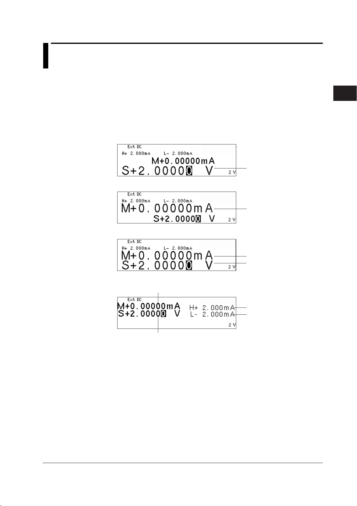
3
2
1
3.8 Basic Operation of Keys and Rotary Knob
This section describes the basic operations of the keys and rotary knob on the GS610.
Basic Key Operations
Switching the Display
3
Instrument Preparation and Common Operations
1. Press ESC (DISPLAY). The displays are displayed cyclically in the following
order each time you press the ESC (DISPLAY) key: one-value (source) display,
one-value (measure) display, two-value (source and measure) display, fourvalue (source, measure, and limiter values (Hi and Lo)) display.
One-Value (Source) Display
Source value
One-Value (Measure) Display
Measured value
Two-Value (Source and Measure) Display
Measured value
Source value
Four-Value (Source, Measure, and Limit Values (Hi and Lo)) Display
Measured value
High limiter value
Low limiter value
Source value
IM 765501-01E
3-17

3.8 Basic Operation of Keys and Rotary Knob
Displaying the Setup Menu of Panel Keys
1. Press a key to display a corresponding setup menu.
2. Press the soft key corresponding to the desired setup menu item.
C
A
B
A: Press the corresponding soft key to switch the setting. The underlined item is
selected.
B: Press the corresponding soft key to display the selection menu. Press the soft
key corresponding to a selection to make the selection.
C: Press the corresponding soft key to select the item to be changed with the
numeric keys or rotary knob. Enter the value directly by pressing the numeric
keys or set the value by turning the rotary knob. Press the BS (backspace) key
and right arrow key to move across the digits.
Note
If the setup menu shows Next 1/2, you can press the Next 1/2 soft key to show the 2/2 menu.
To show the 1/2 menu again, press the Next 2/2 soft key.
Clearing the Setup Menu
Press ESC (DISPLAY) to switch to the numeric display. If the menu that is
shown is under multiple menu levels, press ESC(DISPLAY) to move up a level
in the menu hierarchy. To switch to the numeric display, press ESC(DISPLAY)
multiple times.
Note
In the procedural explanations in this manual, the procedure to clear the setup menu are not
described.
3-18 IM 765501-01E

3
2
1
3.9 Entering Values
G S 61 0
SOU RCE MEA SURE UNI T
Entering Values Using the Rotary Knob
Select the setup item with a soft key. Then, turn the rotary knob to change the value in
the numeric entry area (highlighted area). To move across digits, press the BS
(backspace) key or the right arrow key.
Entering Values Using Numeric Keys
You can enter a value for the item that has a numeric entry area (highlighted area)
shown by pressing the numeric keys. Press the BS key to clear the entered characters
one at a time.
GS610
SOURCE MEASURE UNIT
AVER AGE
4 WIRE
KEY LOCK
REMOTE
DISPLAY
ESC
Highlighted area
BS
BS (backspace) key
Rotary knob
Turn the rotary knob to the right to increase the value.
Turn the rotary knob to the left to decrease the value.
789
456
123
.
+
0
-
Numeric keys
Enter the value directly.
Right arrow key
3
Instrument Preparation and Common Operations
IM 765501-01E
3-19

3
2
1
Chapter 4 Trigger Setting, Connection Type (Remote Sense and Local Sense), and USB Storage Function
4.1 Setting the Trigger
Procedure
DISPLAY
ESC
SOURCE
MODE
AUTO
RANGE
LIMIT
MENU
OUTPUT CONTROL
SWEEP
START
ZERO
RANGE
STORE
MENU
RECALL
POWER
MEASURE
AUTO
RANGE
MATH
COMPARE
LOCAL
MISC
I
V
Ω
MEASURE
NULL
VALUE
TIME
KEY LOCK
SHIFT
Selecting the Trigger Mode
1. Press SHIFT+TRIG(MODE) to display the TrigMode menu.
2. Select the desired trigger mode from Int, Ext, and Imm.
If the measurement is OFF (Measure OFF) (see section 7.1, “Turning the
Measurement ON/OFF”), Imm cannot be selected.
• To exit the menu during operation, press
ESC at the upper left of the operation
panel.
• In the procedural explanation below, the
VS IS
SOURCE
phrase “rotary knob, numeric keys, <,
and >” are used to refer to the operation
of selecting or setting items or entering
values using the rotary knob, numeric
keys, , and keys (BS key and
TRIG
MODE
OUTPUT
right arrow key). For details on the
operation using the rotary knob, numeric
keys, , and , see sections 3.8 or
3.9.
4
Trigger Setting, Connection Type (Remote Sense and Local Sense), and USB Storage Function
If the trigger mode is set to Int, proceed to step 3.
Setting the Repeat Period
3. Press TIME to display the Time menu.
4. Press the Period soft key.
5. Use the rotary knob or numeric keys and < and > keys to set the repeat
period.
6. If you use the numeric keys, press a soft key corresponding to the desired unit
or the Enter soft key to confirm the setting.
Manual Trigger
A trigger is activated each time you press TRIG.
IM 765501-01E
4-1

4.1 Setting the Trigger
Explanation
Trigger Mode
There are three trigger modes for starting the source measure cycle.
Int (Internal): Periodic internal trigger.
Ext (External): Manual trigger by applying an external signal or pressing the TRIG
key.
Imm (Immediate):Starts the next source measure cycle immediately after the current
source measure cycle is complete.
The selected trigger mode is used to trigger the following operations.
• Source measure cycle measurement and pulse generation
• Start the sweep when the sweep function is enabled
Repeat Period
If the trigger mode is set to Int, the repeat period is valid. The trigger is activated
according to the specified repeat period. When a trigger is activated, the TRIG key
illuminates to notify the trigger generation.
The selectable range is 100 µs to 3600.000000 s.
Repeat period
(Period Time)
Tri gg er (Int)
Source
measure
cycle
Repeat period
(Period Time)
Repeat period
(Period Time)
Manual Trigger
A trigger is activated when you press the TRIG key regardless of the selected trigger
mode.
<<Corresponding Command Mnemonic>>
:TRIGger:SOURce
:TRIGger:TIMer
*TRG
4-2 IM 765501-01E

3
2
1
4.2 Connection Type (Remote Sense and Local Sense)
Procedure
• To exit the menu during operation, press
ESC at the upper left of the operation
panel.
• In the procedural explanation below, the
VS IS
SOURCE
phrase “rotary knob, numeric keys, <,
and >” are used to refer to the operation
of selecting or setting items or entering
values using the rotary knob, numeric
keys, , and keys (BS key and
TRIG
MODE
OUTPUT
right arrow key). For details on the
operation using the rotary knob, numeric
keys, , and , see sections 3.8 or
3.9.
Explanation
DISPLAY
ESC
SOURCE
MODE
AUTO
RANGE
LIMIT
MENU
OUTPUT CONTROL
SWEEP
START
ZERO
RANGE
STORE
MENU
RECALL
POWER
MEASURE
AUTO
RANGE
MATH
COMPARE
LOCAL
MISC
I
V
Ω
MEASURE
NULL
VALUE
TIME
KEY LOCK
SHIFT
Selecting the Connection Type (Remote Sense or Local Sense)
1. Press MISC to display the MISC menu.
2. Press the Wire soft key to select 4W or 2W. If you select 4W, the remote sense
indicator (4WIRE) at the left of the display illuminates.
The GS610 has two types of sensing, 2W and 4W.
2W: Two-terminal connection (local sense)
4W: Four-terminal connection (remote sense)
The connection diagrams are given on the next page.
4
Trigger Setting, Connection Type (Remote Sense and Local Sense), and USB Storage Function
If the current flowing through the Hi and Lo terminals is small, select two-terminal
connection (2W). When the output current is large, a voltage error occurs between the
Hi and Lo terminals that are being sensed due to the effects of the lead wire resistance.
In such case, select four-terminal connection (4W) and connect the measurement lead
from the SENSE terminal close to the DUT. This enables the voltage to be sensed with
the effects of the lead wire resistance reduced. This function is effective when the
current is large and the voltage appearing at the DUT is small such as in a low
resistance measurement.
Note
When making a four-terminal connection, be careful that the connection to the SENSE
terminal does not get cut. If it does, an error occurs in the voltage between the Hi and Lo
terminals, because the voltage is not sensed correctly.
When making a two-terminal connection, use the OUTPUT terminals. If the SENSE terminal
is used, the GS610 cannot generate the voltage or current correctly and can cause a
malfunction.
IM 765501-01E
4-3
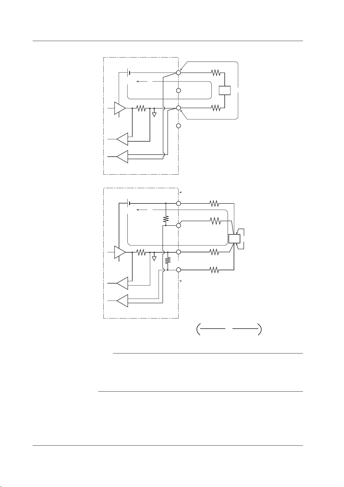
4.2 Connection Type (Remote Sense and Local Sense)
• Two-terminal connection
GS610
I
o
×
1
Current
sense
Voltage sense
• Four-terminal connection
GS610
I
o
40kΩ
r
2
OUTPUT Hi
V
SENSE Hi
DUT
r
1
o
OUTPUT Lo
SENSE Lo
An error equal to Io × (r1 + r2) occurs
DUT: Device Under Test
r2
OUTPUT HI
r4
SENSE HI
DUT
Vo
r1
×1
Current
sense
Voltage sense
An error approximately equal to Io ×
OUTPUT LO
40kΩ
SENSE LO
DUT: Device Under Test
40kΩ+r
r3
r
• r
1
3
3+r1
+
40kΩ+r4+r
r
• r
2
4
2
occurs, but the effects are small if r1 to r4 are adequately small.
Note
If 4W (four-terminal connection) is used, the source voltage between the Hi OUTPUT and Lo
OUTPUT terminals is greater than the voltage generated at the load. If the source voltage
between the Hi OUTPUT and Lo OUTPUT terminals exceeds the source range, the GS610
cannot generate the voltage correctly, and abnormal load detection may be activated causing
the output to be turned OFF. Be sure that the source voltage between the Hi OUTPUT and
Lo OUTPUT terminals do not exceed the source range of the range setting.
<<Corresponding Command Mnemonic>>
:SENSe:RSENse
4-4 IM 765501-01E

3
2
1
4.3 USB Storage Function
Connecting the USB Cable
1. Connect one end of the USB cable to the USB port on the GS610 rear panel.
GP-IB
IN
TRIG /
SWEEP /
CTRL
ETHERNET
100BASE-TX
USB port
2. Connect the other end of the cable to the USB port on the PC.
3. After connecting the USB cable correctly, turn ON the power switch of the
GS610. Two removable disks named GS610ROM and GS610RAM appear
within My Computer on the PC.
(IEEE488)
OUT
ACT
LINK
USB
220 - 240V AC
100 - 120V
60Hz
200VA MAX
50
EXT I
O
SERIAL (RS-232)
4
Trigger Setting, Connection Type (Remote Sense and Local Sense), and USB Storage Function
IM 765501-01E
4-5

4.3 USB Storage Function
USB Storage Function
GS610ROM
A non-volatile disk with preset directories for different purposes. Various files are stored
in the appropriate directories.
• MATH
Stores definition files of equations that you select when carrying out computation
using equations.
When shipped from the factory and when the disk is formatted, built-in computation
files are stored in this directory.
• PROGRAM
Stores program sweep pattern files that you select when carrying out program sweep.
When shipped from the factory or when the disk is formatted, sample pattern files are
stored in this directory.
• SETUP
Stores the GS610 panel setup data that you select when settings are loaded.
When shipped from the factory or when the disk is formatted, a default setup file is
stored in this directory.
GS610RAM
A RAM disk that is automatically formatted when the power is turned ON. It is a volatile
disk used to exchange files with the PC. The result file (Result.csv) is created in this
directory when the storage operation is carried out. If the settings are saved to the
GS610RAM, the current settings are saved to a file named Setup.txt.
When updating the system firmware, the system file (System.bin) is written in this
directory from a PC. For details, see section 17.5, “Updating the System Firmware.”
4-6 IM 765501-01E

3
2
1
Formatting the Disk
Procedure
DISPLAY
ESC
STORE
RECALL
POWER
4.3 USB Storage Function
If GS610ROM and GS610RAM cannot be detected on the PC, if you wish to set the
GS610 to factory default conditions, or if the disk is corrupt, you must format the disk.
• To exit the menu during operation, press
ESC at the upper left of the operation
panel.
• In the procedural explanation below, the
VS IS
SOURCE
phrase “rotary knob, numeric keys, <,
and >” are used to refer to the operation
of selecting or setting items or entering
values using the rotary knob, numeric
keys, , and keys (BS key and
TRIG
MODE
OUTPUT
right arrow key). For details on the
operation using the rotary knob, numeric
keys, , and , see sections 3.8 or
MENU
MEASURE
AUTO
RANGE
MATH
COMPARE
LOCAL
MISC
I
V
Ω
MEASURE
NULL
VALUE
TIME
KEY LOCK
SHIFT
SOURCE
MODE
AUTO
RANGE
LIMIT
MENU
OUTPUT CONTROL
SWEEP
START
ZERO
RANGE
3.9.
1. Press MISC to display the MISC menu.
2. Press the System soft key.
4
Trigger Setting, Connection Type (Remote Sense and Local Sense), and USB Storage Function
3. Press the Next 1/2 soft key.
4. Press the DiskFormat soft key.
5. Press the Exec soft key to execute the disk format.
Note
• Always format the disk from the GS610 menu. If you format the disk from a PC, default
directories such as MATH and default files are not created.
• You can also create subdirectories and write files to the disk, but be sure that the disk
does not become full.
• Do not change the existing directory names such as MATH. If you do, you will no longer
be able to select files from the GS610.
IM 765501-01E
4-7
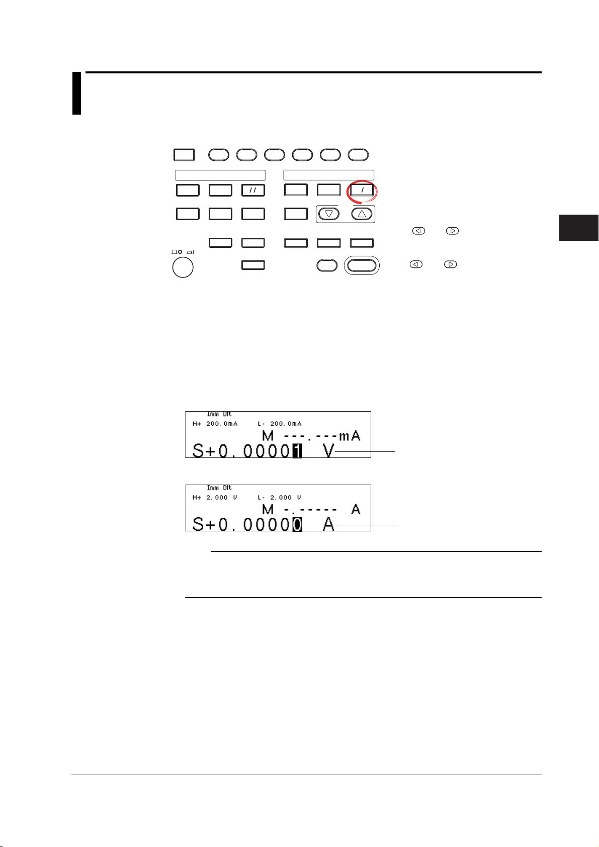
3
2
1
4
Chapter 5 Source
5.1 Switching the Source Function
Procedure
DISPLAY
ESC
SOURCE
MODE
AUTO
RANGE
LIMIT
MENU
OUTPUT CONTROL
SWEEP
START
ZERO
RANGE
VS IS
SOURCE
TRIG
MODE
OUTPUT
Explanation
MEASURE
STORE
MENU
RECALL
POWER
AUTO
RANGE
MATH
COMPARE
LOCAL
MISC
I
V
Ω
MEASURE
NULL
VALUE
TIME
KEY LOCK
SHIFT
Press VS/IS.
Each time you press the key, the source function toggles between voltage (V,
mV) and current (µA, mA, A).
The source function (S on the display) is indicated by the unit of the source value (V for
voltage and A for current).
• To exit the menu during operation, press
ESC at the upper left of the operation
panel.
• In the procedural explanation below, the
phrase “rotary knob, numeric keys, <,
and >” are used to refer to the operation
of selecting or setting items or entering
values using the rotary knob, numeric
keys, , and keys (BS key and
right arrow key). For details on the
operation using the rotary knob, numeric
keys, , and , see sections 3.8 or
3.9.
5
Source
Example
When the source function is voltage
Source value unit
When the source function is current
Source value unit
Note
• If you switch the source function, the output is turned OFF. The source value shows the
value that was set previously for the switched source function.
• Be sure to check that the load is connected correctly before turning the output ON after
switching the source function.
<<Corresponding Command Mnemonic>>
:SOURce:FUNCtion
IM 765501-01E
5-1
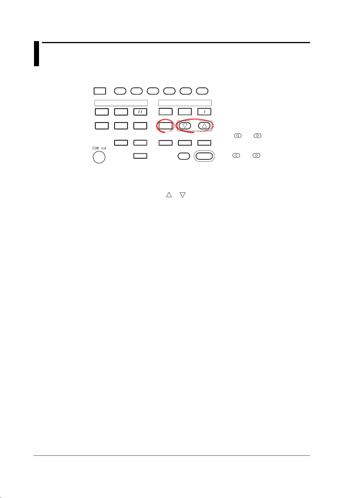
5.2 Setting the Source Range Setting
Procedure
DISPLAY
ESC
SOURCE
MODE
AUTO
RANGE
LIMIT
MENU
OUTPUT CONTROL
SWEEP
START
ZERO
RANGE
STORE
MENU
RECALL
POWER
MEASURE
AUTO
RANGE
MATH
COMPARE
LOCAL
MISC
I
V
Ω
MEASURE
NULL
VALUE
TIME
KEY LOCK
SHIFT
There are two source range settings, fixed range and auto range.
Changing the Fixed Range Setting
Press the RANGE
or key to change the source range setting.
Auto Range
Press AUTO RANGE under SOURCE. The auto range function is turned ON,
and the AUTO RANGE key illuminates.
• To exit the menu during operation, press
ESC at the upper left of the operation
panel.
• In the procedural explanation below, the
VS IS
SOURCE
phrase “rotary knob, numeric keys, <,
and >” are used to refer to the operation
of selecting or setting items or entering
values using the rotary knob, numeric
keys, , and keys (BS key and
TRIG
MODE
OUTPUT
right arrow key). For details on the
operation using the rotary knob, numeric
keys, , and , see sections 3.8 or
3.9.
5-2 IM 765501-01E

3
2
1
4
Explanation
5.2 Setting the Source Range Setting
Note
• If you change the range setting while a capacitive or inductive load such as a capacitor or
coil is connected, an abnormal load may be detected due to the energy built up in the load
may cause the output to be turned OFF.
• When you change the range setting, the source level zero state occurs transiently. If you
wish to vary the source level continuously, set the maximum range setting that is needed
so that the range setting does not change.
Fixed Range
The GS610 generates the source signal at the selected range setting. The range setting
can be changed with the RANGE
generated.
Voltage Source Range Setting
Source Range Setting Source Range Resolution
200 mV ±205.000 mV 1 µV
2 V ±2.05000 V 10 µV
12 V ±12.0000 V 100 µV
20 V ±20.5000 V 100 µV
30 V ±30.000 V 1 mV
60 V ±60.000 V 1 mV
110 V ±110.000 V 1 mV
and keys while the source signal is being
5
Source
Current Source Range Setting
Source Range Setting Source Range Resolution
20 µA ±20.5000 µA 100 pA
200 µA ±205.000 µA1 nA
2 mA ±2.05000 mA 10 nA
20 mA ±20.5000 mA 100 nA
200 mA ±205.000 mA 1 µA
0.5 A ±0.50000 A 10 µA
1 A ±1.00000 A 10 µA
2 A ±2.00000 A 10 µA
3 A ±3.20000 A 10 µA
Note
• Changing the range setting normally does not change the specified source value.
However, if the fractional part is rounded in the source range of the new range setting or
the source value falls outside the source range, the source value is set to zero.
• If you enter a source value exceeding the specified range setting, the maximum value of
the source range is displayed, and a beep sound (see section 11.4, “Turning the Beep
Sound ON/OFF”) is generated (when the beep sound is enabled).
Auto Range
When turned ON, the range setting with the highest resolution that includes the source
level is automatically selected. There is no need to select the range setting. However,
switching the range setting takes time, and the source level may be discontinuous, if the
range setting switches as a result of changing the source level.
<<Corresponding Command Mnemonic>>
:SOURce:VOLTage:RANGe
:SOURce:VOLTage:RANGe:AUTO
:SOURce:CURRent:RANGe
:SOURce:CURRent:RANGe:AUTO
IM 765501-01E
5-3

5.3 Setting the Limiter
Procedure
DISPLAY
ESC
MEASURE
STORE
MENU
RECALL
POWER
AUTO
RANGE
MATH
COMPARE
LOCAL
MISC
Turning the Limiter ON/OFF
1. Press SHIFT+LIMIT (MENU) to display the limiter setup menu.
2. Press the Limit soft key to turn the limiter ON or OFF.
Turning the Tracking ON/OFF
3. Press the Tracking soft key to turn the tracking function ON or OFF.
I
V
Ω
MEASURE
NULL
VALUE
TIME
KEY LOCK
SHIFT
SOURCE
MODE
AUTO
RANGE
LIMIT
MENU
OUTPUT CONTROL
SWEEP
START
ZERO
RANGE
• To exit the menu during operation, press
ESC at the upper left of the operation
panel.
• In the procedural explanation below, the
VS IS
SOURCE
phrase “rotary knob, numeric keys, <,
and >” are used to refer to the operation
of selecting or setting items or entering
values using the rotary knob, numeric
keys, , and keys (BS key and
TRIG
MODE
OUTPUT
right arrow key). For details on the
operation using the rotary knob, numeric
keys, , and , see sections 3.8 or
3.9.
Setting the Limiter Value
4. Press LIMIT to display the limiter value setup screen.
5. Use the rotary knob or numeric keys and < and > keys to set the limiter
value.
If tracking is turned ON in step 3, the high and low limiter values can be set
simultaneously.
If tracking is turned OFF in step 3, the high and low limiter values can be set
separately.
6. If you set the limiter value using the numeric keys, press the desired unit or the
Enter soft key.
5-4 IM 765501-01E

3
2
1
4
Explanation
5.3 Setting the Limiter
Turning the Limiter ON/OFF
ON: Apply the limit with the specified limiter values.
OFF: The limiter is activated at the maximum value of the source range (see section
2.2). However, the limiter value is not displayed.
Tracking
ON: Set the limiter values with the same absolute value but with opposite signs.
Example Hi limiter value: +1.000 mA
Lo limiter value: –1.000 mA
OFF: Set the limiter values to arbitrary values with opposite signs.
Example Hi limiter value: +1.500 mA
Lo limiter value: –1.000 mA
Setting the Limiter Value
The current limiter is selected when generating voltage, and the voltage limiter is
automatically selected when generating current.
The optimal range for the specified limiter values is automatically selected.
• Limiter Range
Current
|Limiter Value|
0.10 µA to 20.00 µA 20 µA 10 nA 100 nA
20.1 µA to 200.0 µA 200 µA 100 nA 1 µA
0.201 mA to 2.000 mA 2 mA 1 µA 10 µA
2.01 mA to 20.00 mA 20 mA 10 µA 100 µA
20.1 mA to 200.0 mA 200 mA 100 µA1 mA
0.201 A to 3.200 A 3 A 1 mA 10 mA
1 When tracking is OFF, |Hi| or |Lo|, whichever is greater.
2 Minimum value when tracking is OFF.
Voltage
|Limiter Value|
1.0 mV to 200.0 mV 200 mV 100 µV1 mV
0.201 V to 2.000 V 2 V 1 mV 10 mV
2.01 V to 20.00 V 20 V 10 mV 100 mV
20.1 V to 110.0 V 110 V 100 mV 1 V
3 When tracking is OFF, |Hi| or |Lo|, whichever is greater.
4 Minimum value when tracking is OFF.
1
3
Range Setting Resolution Minimum Limit Value
Range Setting Resolution Minimum Limit Value
5
Source
2
4
Display When the Limiter Is Activated
When the high limiter is activated: High limiter activation display (H)
When the low limiter is activated: Low limiter activation display (L)
Note
• If the limit values are set outside the source range of the selected range setting, the limiter
is activated at the boundary of the source range.
• If the limiter range is changed, the limiter level is transiently reduced to 10% of the range
setting and moves sequentially to the adjacent ranges.
<<Corresponding Command Mnemonic>>
:SOURce:VOLTage:PROTection[:STATe]
:SOURce:VOLTage:PROTection:LINKage
:SOURce:VOLTage:PROTection:ULIMit
:SOURce:VOLTage:PROTection:LLIMit
:SOURce:CURRent:PROTection[:STATe]
:SOURce:CURRent:PROTection:LINKage
:SOURce:CURRent:PROTection:ULIMit
IM 765501-01E
:SOURce:CURRent:PROTection:LLIMit
5-5

5.4 Setting the DC Source Mode
Procedure
DISPLAY
ESC
MEASURE
STORE
MENU
RECALL
POWER
AUTO
RANGE
MATH
COMPARE
LOCAL
MISC
I
V
Ω
MEASURE
NULL
VALUE
TIME
KEY LOCK
SHIFT
1. Press MODE to display the source mode menu.
Selecting the DC Source Mode
2. Press the DC soft key.
Setting the Source Value (Source Level)
3. Use the rotary knob or numeric keys and < and > keys to set the source
value.
SOURCE
MODE
AUTO
RANGE
LIMIT
MENU
OUTPUT CONTROL
SWEEP
START
ZERO
RANGE
VS IS
SOURCE
TRIG
MODE
OUTPUT
• To exit the menu during operation, press
ESC at the upper left of the operation
panel.
• In the procedural explanation below, the
phrase “rotary knob, numeric keys, <,
and >” are used to refer to the operation
of selecting or setting items or entering
values using the rotary knob, numeric
keys, , and keys (BS key and
right arrow key). For details on the
operation using the rotary knob, numeric
keys, , and , see sections 3.8 or
3.9.
4. If you use the numeric keys, press a soft key corresponding to the desired unit
or the Enter soft key to confirm the setting.
5-6 IM 765501-01E
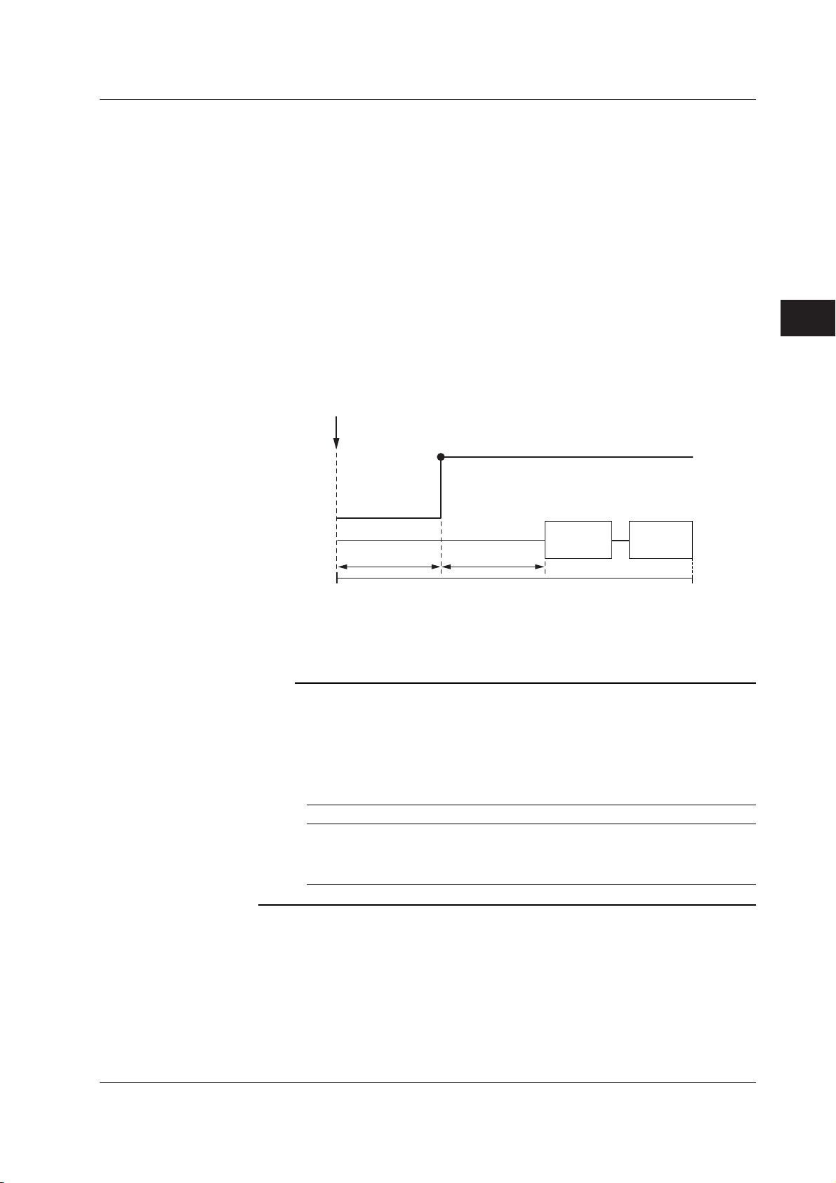
3
2
1
4
Explanation
5.4 Setting the DC Source Mode
DC Source Mode
If the sweep mode (see section 2.6, “Sweep”) is ON in DC source mode, the source level
changes after a time specified by the source delay elapses from the point in which the
trigger is activated. Then, measurement starts after a time specified by measurement
delay elapses. When the measurement and computation are complete, one source
measure cycle is finished.
However, if you change the source level with a key or a communication command in the
middle of a source measure cycle, the source level changes immediately without waiting
for the source delay or measure delay, and the internal trigger phase is reset.
If the sweep mode is OFF, the source level is maintained, and the source measure cycle
is carried out.
If the measurement function is turned OFF (see section 2.4, “Measurement”), measure
delay, measurement, and computation are not carried out. The time when the source
level changes is the end of the source measure cycle.
Trigger
Current source level
Source
Previous source
level
5
Source
Measurement
Source delay
Selectable Range of Source Values (Source Levels)
See section 5.2, “Source Range Settings.”
Measurement
delay
Source measure cycle
Measurement Computation
Note
The output capacitance indicated below exists between the Hi OUTPUT and Lo OUTPUT
terminals of the GS610. This capacitance produces the following effects.
• If the load changes drastically such as when a short circuit occurs when generating
voltage, a large transient discharge current is generated from the output capacitance.
• If a voltage source (power supply, amplifier, signal generator, etc.) is connected as a load,
the load voltage source may be unstable due to the output capacitance.
• Take the time it takes for the output capacitance to be charged and discharged when
determining the response time of the source voltage.
Current Range Setting, Current Limiter Range Output Capacitance
20 µA, 200 µA, 2 mA 5 µF or less
20 mA 0.55 µF or less
200 mA 0.05 µF or less
3 A, 2 A, 1 A, 0.5 A 0.02 µF or less
<<Corresponding Command Mnemonic>>
:SOURce:SHAPe
:SOURce:VOLTage:LEVel
:SOURce:CURRent:LEVel
IM 765501-01E
5-7

5.5 Setting the Pulse Source Mode
Procedure
DISPLAY
ESC
SOURCE
MODE
AUTO
RANGE
LIMIT
MENU
OUTPUT CONTROL
SWEEP
START
ZERO
RANGE
STORE
MENU
RECALL
POWER
MEASURE
AUTO
RANGE
MATH
COMPARE
LOCAL
MISC
I
V
Ω
MEASURE
NULL
VALUE
TIME
KEY LOCK
SHIFT
1. Press MODE to display the source mode menu.
Selecting the Pulse Source Mode
2. Press the Pulse soft key.
Setting the Source Value (Source Level)
3. Use the rotary knob or numeric keys and < and > keys to set the source
value.
• To exit the menu during operation, press
ESC at the upper left of the operation
panel.
• In the procedural explanation below, the
VS IS
SOURCE
phrase “rotary knob, numeric keys, <,
and >” are used to refer to the operation
of selecting or setting items or entering
values using the rotary knob, numeric
keys, , and keys (BS key and
TRIG
MODE
OUTPUT
right arrow key). For details on the
operation using the rotary knob, numeric
keys, , and , see sections 3.8 or
3.9.
4. If you use the numeric keys, press a soft key corresponding to the desired unit
or the Enter soft key to confirm the setting.
Setting the Pulse Base Value
5. Press SHIFT+VS/IS(SOURCE) to display the SOURCE menu.
6. Press the Pulse Base soft key.
7. Use the rotary knob or numeric keys and < and > keys to set the pulse base
value.
5-8 IM 765501-01E
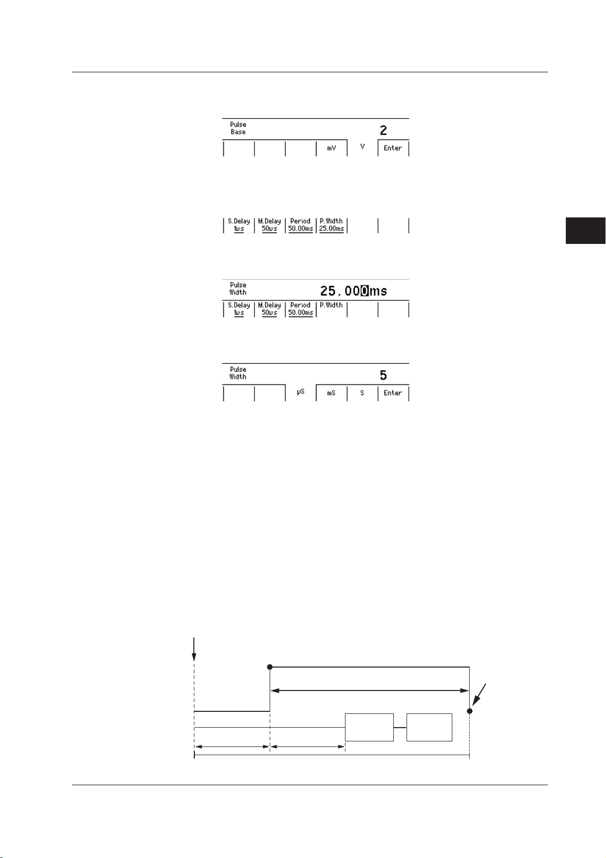
3
2
1
4
5.5 Setting the Pulse Source Mode
8. If you use the numeric keys, press a soft key corresponding to the desired unit
or the Enter soft key to confirm the setting.
Setting the Pulse Width
9. Press TIME to display the TIME menu.
10. Press the P.Width soft key.
11. Use the rotary knob or numeric keys and < and > keys to set the source
voltage.
12. If you use the numeric keys, press a soft key corresponding to the desired unit
or the Enter soft key to confirm the setting.
5
Source
Explanation
Pulse Source Mode
In pulse source mode, the pulse is specified by two values, the pulse base value and the
source level. The minimum pulse width is 100 µs.
As with the DC source mode, the source level changes after a time specified by the
source delay elapses from the point in which the trigger is activated. Furthermore, the
measurement starts after a time specified by the measurement delay elapses. The
source level changes at the same the measure delay is activated and returns to the
pulse base value after the pulse width. A source measure cycle is finished at the end of
the pulse or at the end of the measurement and computation, whichever comes later.
If the measurement function (see section 2.4, “Measurement”) is turned OFF, measure
delay, measurement, and computation are not carried out. The end of the pulse is the
end of a source measure cycle.
When the End of the Measurement and Computation Is after the End of the Pulse
Generation
Trigger
Current source level
Source
Pulse width
Pulse source end
Base pulse value
Measurement
Source delay
Measurement
delay
Measurement Computation
Base pulse value
IM 765501-01E
Source measure cycle
5-9

5.5 Setting the Pulse Source Mode
When the End of the Measurement and Computation Is before the End of the Pulse
Generation
Source
Trigger
Current source level
Pulse width
Base pulse value Base pulse value
Pulse source end
Measurement
Source delay
Measurement
delay
Source measure cycle
Measurement
Computation
Selectable Range Source Values (Source Level)
See section 5.2, “Source Range Settings.”
Selectable Range of Pulse Base Values
The pulse base value is the same as the source value (source level).
Note
If the source range setting is auto range, the range setting appropriate for the larger of the
two values |source value| and |pulse base value| is applied.
Selectable Range of Pulse Width
100 µs to 3600.000000 s
Note
If a capacitive or inductive load is connected, the limiter is activated transiently, and the
settling time is increased.
If a capacitive load is connected, the output capacitance of the GS610 is also added. Be
careful of the settling time.
<<Corresponding Command Mnemonic>>
:SOURce:SHAPe
:SOURce:VOLTage:LEVel
:SOURce:VOLTage:PBASe
:SOURce:CURRent:LEVel
:SOURce:CURRent:PBASe
:SOURce:PULSe:WIDTh
5-10 IM 765501-01E

3
2
1
4
5.6 Setting the Source Delay
Procedure
DISPLAY
ESC
MEASURE
STORE
MENU
RECALL
POWER
AUTO
RANGE
MATH
COMPARE
LOCAL
MISC
I
V
Ω
MEASURE
NULL
VALUE
TIME
KEY LOCK
SHIFT
1. Press TIME to display the Time menu.
2. Press the S.Delay soft key to display the source delay setup screen.
3. Use the rotary knob or numeric keys and < and > keys to set the source
delay.
SOURCE
MODE
AUTO
RANGE
LIMIT
MENU
OUTPUT CONTROL
SWEEP
START
ZERO
RANGE
• To exit the menu during operation, press
ESC at the upper left of the operation
panel.
• In the procedural explanation below, the
VS IS
SOURCE
phrase “rotary knob, numeric keys, <,
and >” are used to refer to the operation
of selecting or setting items or entering
values using the rotary knob, numeric
keys, , and keys (BS key and
TRIG
MODE
OUTPUT
right arrow key). For details on the
operation using the rotary knob, numeric
keys, , and , see sections 3.8 or
3.9.
5
Source
4. If you use the numeric keys, press a soft key corresponding to the desired unit
or the Enter soft key to confirm the setting.
IM 765501-01E
5-11

5.6 Setting the Source Delay
Explanation
Source Delay
The wait time from trigger input to the start of source change can be specified.
Selectable Range
1 µs to 3600.000000 s
Trigger
Int or Ext
Source
Source delay
Source value
Measurement delay
Measurement
Calculation
Measurement time
Source measure cycle
<<Corresponding Command Mnemonic>>
:SOURce:DELay
5-12 IM 765501-01E

3
2
1
4
5.7 Turning the Output ON/OFF
Procedure
DISPLAY
ESC
SOURCE
MODE
AUTO
RANGE
LIMIT
MENU
OUTPUT CONTROL
SWEEP
START
ZERO
RANGE
VS IS
SOURCE
TRIG
MODE
OUTPUT
STORE
MENU
RECALL
POWER
Output ON
Output OFF
MEASURE
AUTO
RANGE
MATH
COMPARE
LOCAL
MISC
I
V
Ω
MEASURE
NULL
VALUE
TIME
KEY LOCK
SHIFT
Press OUTPUT. The OUTPUT key illuminates while the output is ON.
Press OUTPUT while generating the signal to stop the output. When the output
stops, the OUTPUT key turns OFF.
• To exit the menu during operation, press
ESC at the upper left of the operation
panel.
• In the procedural explanation below, the
phrase “rotary knob, numeric keys, <,
and >” are used to refer to the operation
of selecting or setting items or entering
values using the rotary knob, numeric
keys, , and keys (BS key and
right arrow key). For details on the
operation using the rotary knob, numeric
keys, , and , see sections 3.8 or
3.9.
5
Source
Explanation
Output ON
The output relay is activated, and source measure cycle is repeated.
Output OFF
The output relay is disconnected, and the source measure cycle stops.
Note
When the output relay is activated, the source level is set to zero.
• When Output Is ON
The output relay turns ON with the source level set to zero. After the output relay is
activated, the source level is changed to the specified source value.
• When Output Is OFF
The source level is set to zero, and the output relay is turned OFF.
<<Corresponding Command Mnemonic>>
:OUTPut[:STATe]
IM 765501-01E
5-13

5.8 Zero Generation
Procedure
DISPLAY
ESC
MEASURE
STORE
MENU
RECALL
POWER
AUTO
RANGE
MATH
COMPARE
LOCAL
MISC
Zero Generation
Press ZERO when generating the signal or press the SHIFT+ZERO key when
the output is OFF to generate a zero level signal.
Setting the Zero Offset
1. Press SHIFT+VS/IS(SOURCE) to display the SOURCE menu.
2. Press the Zero Offset soft key.
I
V
Ω
MEASURE
NULL
VALUE
TIME
KEY LOCK
SHIFT
SOURCE
MODE
AUTO
RANGE
LIMIT
MENU
OUTPUT CONTROL
SWEEP
START
ZERO
RANGE
• To exit the menu during operation, press
ESC at the upper left of the operation
panel.
• In the procedural explanation below, the
VS IS
SOURCE
phrase “rotary knob, numeric keys, <,
and >” are used to refer to the operation
of selecting or setting items or entering
values using the rotary knob, numeric
keys, , and keys (BS key and
TRIG
MODE
OUTPUT
right arrow key). For details on the
operation using the rotary knob, numeric
keys, , and , see sections 3.8 or
3.9.
3. Use the rotary knob or numeric keys and < and > keys to set the zero offset
voltage.
4. If you use the numeric keys, press a soft key corresponding to the desired unit
or the Enter soft key to confirm the setting.
Zero Source Impedance
5. Press the Zero Z soft key to select Hiz or Loz.
5-14 IM 765501-01E

3
2
1
4
Explanation
5.8 Zero Generation
Zero Generation
When generating voltage, 0 V is generated. When generating current, 0 A is generated.
Setting the Zero Offset
An offset can be specified on the zero value when generating zero output.
Selectable Range of Zero Offset
–110.000 V to 110.000 V
Note
If the zero offset value exceeds the source range of the selected range setting, the zero offset
is set to the upper or lower limit of the range setting.
Setting the Zero Source Impedance
The impedance when generating a zero level signal can be selected.
• When Low Impedance (LoZ) Is Selected When Generating Voltage or When High
Impedance (HiZ) Is Selected When Generating Current
The source value is set to 0.
• When High Impedance (HiZ) Is Selected When Generating Voltage or When Low
Impedance (LoZ) Is Selected When Generating Current
The source value is set to 0, and the limiter is set to 0.5% of the range setting.
5
Source
<<Corresponding Command Mnemonic>>
:OUTPut[:STATe]
:SOURce:VOLTage:ZERO:OFFSet
:SOURce:VOLTage:ZERO:IMPedance
:SOURce:CURRent:ZERO:OFFSet
:SOURce:CURRent:ZERO:IMPedance
IM 765501-01E
5-15
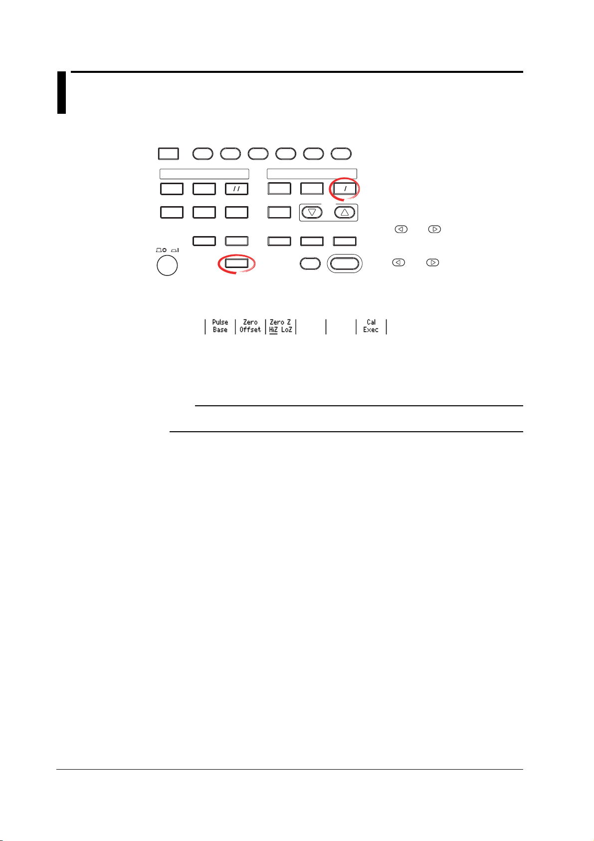
5.9 Offset Calibration
Procedure
DISPLAY
ESC
MEASURE
Explanation
STORE
MENU
RECALL
POWER
AUTO
RANGE
MATH
COMPARE
LOCAL
MISC
1. Press SHIFT+VS/IS(SOURCE) to display the SOURCE menu.
2. Press the CalExec soft key to carry out the calibration.
Carry out calibration when correcting the offset drift of the source value such as due to
temperature changes.
I
V
Ω
MEASURE
NULL
VALUE
TIME
KEY LOCK
SHIFT
SOURCE
MODE
AUTO
RANGE
LIMIT
MENU
OUTPUT CONTROL
SWEEP
START
ZERO
RANGE
• To exit the menu during operation, press
ESC at the upper left of the operation
panel.
• In the procedural explanation below, the
VS IS
SOURCE
phrase “rotary knob, numeric keys, <,
and >” are used to refer to the operation
of selecting or setting items or entering
values using the rotary knob, numeric
keys, , and keys (BS key and
TRIG
MODE
OUTPUT
right arrow key). For details on the
operation using the rotary knob, numeric
keys, , and , see sections 3.8 or
3.9.
Note
The offset calibration is valid only for the range setting at which the calibration is carried out.
The calibration setting is initialized when the power is cycled.
<<Corresponding Command Mnemonic>>
*CAL?
5-16 IM 765501-01E

3
2
1
5
4
Chapter 6 Sweep
6.1 Setting the Linear or Log Sweep
Procedure
DISPLAY
ESC
MEASURE
STORE
MENU
RECALL
POWER
AUTO
RANGE
MATH
COMPARE
LOCAL
MISC
I
V
Ω
MEASURE
NULL
VALUE
TIME
KEY LOCK
SHIFT
1. Press SWEEP to display the SWEEP menu.
2. Press the Mode soft key to display the SWEEP mode menu.
Setting the Linear Sweep
3. Press the Linear soft key. The SWEEP key illuminates. If you select Off, the
key turns OFF.
SOURCE
MODE
AUTO
RANGE
LIMIT
MENU
OUTPUT CONTROL
SWEEP
START
ZERO
RANGE
VS IS
SOURCE
TRIG
MODE
OUTPUT
• To exit the menu during operation, press
ESC at the upper left of the operation
panel.
• In the procedural explanation below, the
phrase “rotary knob, numeric keys, <,
and >” are used to refer to the operation
of selecting or setting items or entering
values using the rotary knob, numeric
keys, , and keys (BS key and
right arrow key). For details on the
operation using the rotary knob, numeric
keys, , and , see sections 3.8 or
3.9.
6
Sweep
Setting the Start Value
4. Press the Start Value soft key.
5. Use the rotary knob or numeric keys and < and > keys to set the start
value.
6. If you use the numeric keys, press a soft key corresponding to the desired
unit or the Enter soft key to confirm the setting.
IM 765501-01E
6-1

6.1 Setting the Linear or Log Sweep
Setting the Stop Value
7. Press the Stop Value soft key.
8. Use the rotary knob or numeric keys and < and > keys to set the stop
9. If you use the numeric keys, press a soft key corresponding to the desired
Setting the Step Value
10. Press the Step Value soft key.
value.
unit or the Enter soft key to confirm the setting.
11. Use the rotary knob or numeric keys and < and > keys to set the step
value.
12. If you use the numeric keys, press a soft key corresponding to the desired
unit or the Enter soft key to confirm the setting.
Setting the Log Sweep
3. Press the Log soft key. The SWEEP key illuminates. If you set the Sweep
mode to Off, the key turns OFF.
Setting the Start Value
4. Press the Start Value soft key.
6-2 IM 765501-01E
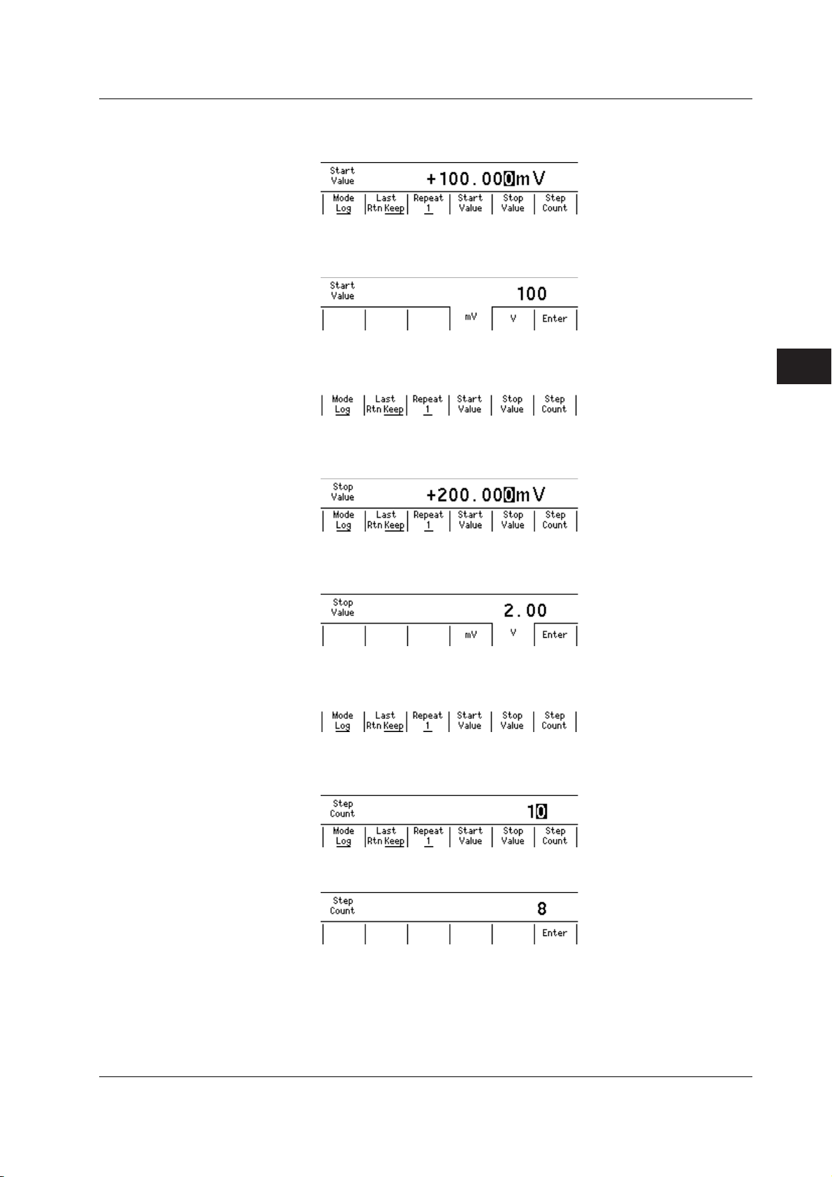
3
2
1
5
4
6.1 Setting the Linear or Log Sweep
5. Use the rotary knob or numeric keys and < and > keys to set the start
value.
6. If you use the numeric keys, press a soft key corresponding to the desired
unit or the Enter soft key to confirm the setting.
Setting the Stop Value
7. Press the Stop Value soft key.
8. Use the rotary knob or numeric keys and < and > keys to set the stop
value.
6
Sweep
9. If you use the numeric keys, press a soft key corresponding to the desired
unit or the Enter soft key to confirm the setting.
Setting the Step Count
10. Press the Step Count soft key.
11. Use the rotary knob or numeric keys and < and > keys to set the step
count.
12. If you use the numeric keys, press the Enter soft key to confirm the setting.
IM 765501-01E
6-3

6.1 Setting the Linear or Log Sweep
Explanation
Linear Sweep
Sweeps using evenly spaced step values that increase linearly from the specified start
value to the stop value.
If the sweep count calculated from the start, stop, and step values exceeds 65535 points,
an error occurs, and the sweep operation can be carried out only up to 65535 points.
• When the source mode is DC
Source level
Initial
value
Start value
Start
Step value
Trigger count Trigger count
Stop value
• When the source mode is pulse
Source level
Step value
Start value
Initial
value
Start
Stop value
Base value
Log Sweep
Sweeps exponentially from the specified start value to the stop value at the specified
step count.
The step count can be set arbitrary in the range of 2 to 65535. However, if the start
value and stop value have opposite signs, an error occurs, and the sweep operation
cannot be carried out.
In addition, if the start value or stop value is 0, an error occurs, and the sweep operation
cannot be carried out.
• When the source mode is DC
Source level
Initial
value
Start value
Start
Stop value
Tri gg er count
Step count
• When the source mode is pulse
Source level
Start value
Initial
value
Start
Tri gg er count
Stop value
Step count
Base value
Note
• Use a fixed range so that the range setting does not change during the sweep operation.
Sweep operation is possible in auto range, but the time of each source measure cycle will
be irregular. In addition, if the range setting changes, the source level will be
discontinuous.
• When fixed range is used, the sweep operation is carried out in the range setting best
suited to the source level with the highest resolution.
<<Corresponding Command Mnemonic>>
:SOURce:MODE
:SOURce:VOLTage:SWEep:SPACing
:SOURce:VOLTage:SWEep:STARt
:SOURce:VOLTage:SWEep:STOP
:SOURce:VOLTage:SWEep:STEP
:SOURce:VOLTage:SWEep:POINts
:SOURce:CURRent:SWEep:SPACing
:SOURce:CURRent:SWEep:STARt
:SOURce:CURRent:SWEep:STOP
:SOURce:CURRent:SWEep:STEP
:SOURce:CURRent:SWEep:POINts
6-4 IM 765501-01E
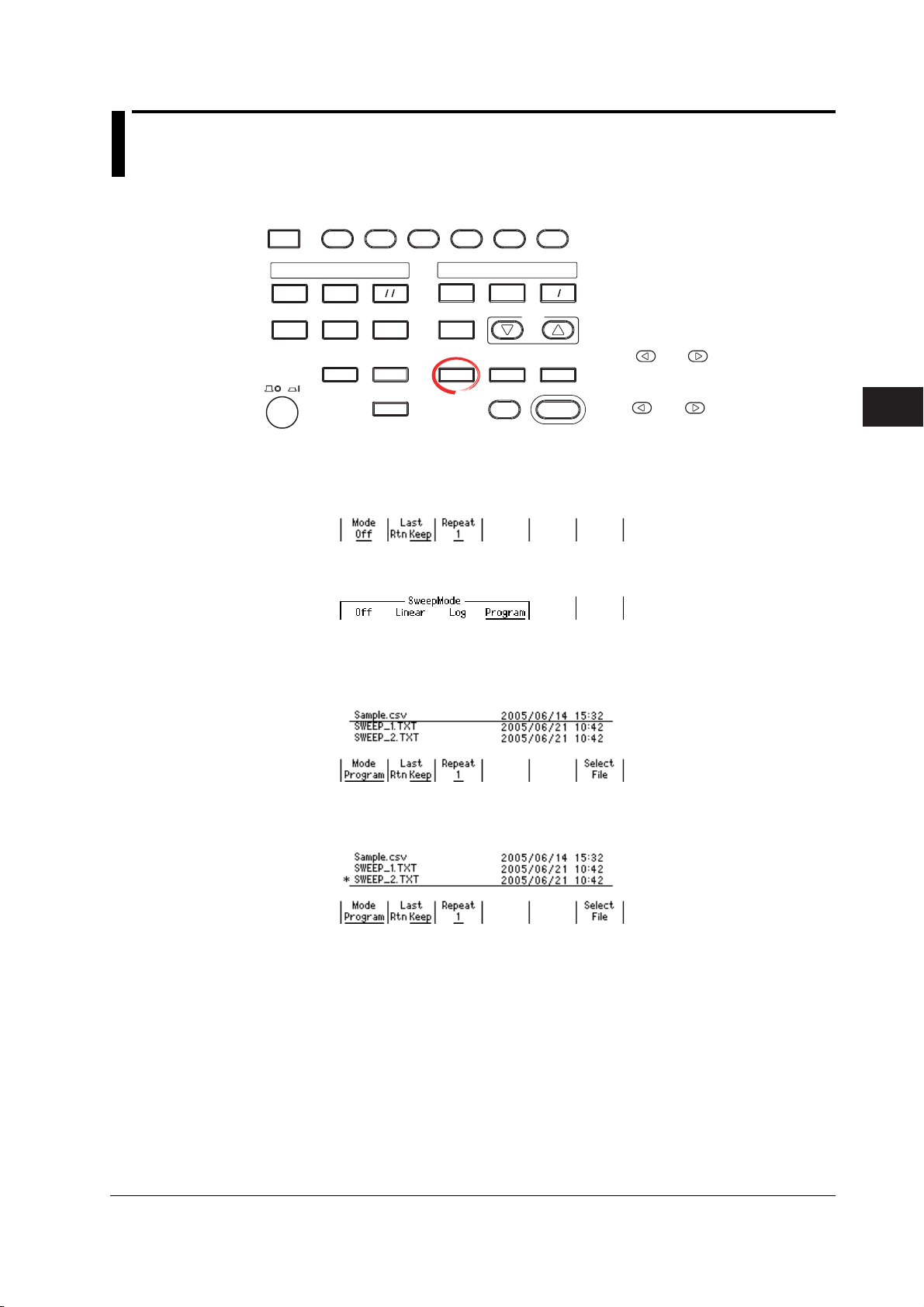
3
2
1
5
4
6.2 Setting the Program Sweep
Procedure
DISPLAY
ESC
MEASURE
STORE
MENU
RECALL
POWER
AUTO
RANGE
MATH
COMPARE
LOCAL
MISC
I
V
Ω
MEASURE
NULL
VALUE
TIME
KEY LOCK
SHIFT
Selecting the Program Sweep Mode
1. Press SWEEP to display the SWEEP menu.
2. Press the Mode soft key to display the SWEEP mode menu.
3. Press the Program soft key.
SOURCE
MODE
AUTO
RANGE
LIMIT
MENU
OUTPUT CONTROL
SWEEP
START
ZERO
RANGE
VS IS
SOURCE
TRIG
MODE
OUTPUT
• To exit the menu during operation, press
ESC at the upper left of the operation
panel.
• In the procedural explanation below, the
phrase “rotary knob, numeric keys, <,
and >” are used to refer to the operation
of selecting or setting items or entering
values using the rotary knob, numeric
keys, , and keys (BS key and
right arrow key). For details on the
operation using the rotary knob, numeric
keys, , and , see sections 3.8 or
3.9.
6
Sweep
Selecting the Pattern File
4. From the pattern files shown, use the rotary knob or numeric keys to select
the file to be used for the program sweep. The selected file is underlined.
5. Press the Select File soft key to confirm the setting. When the setting is
confirmed, an asterisk is placed before the file name.
IM 765501-01E
6-5
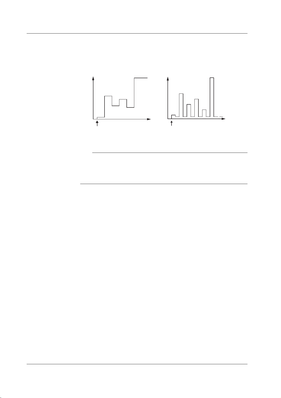
6.2 Setting the Program Sweep
Explanation
Program Sweep
Sweeps according to the values in a pattern file containing an arbitrary sweep pattern.
Program Sweep Example
• When the source mode is DC
• When the source mode is pulse
Source level
Initial
value
Start
Tri gg er count
Source level
Initial
value
Base value
Trigger count
Start
For details on the pattern file of program sweep, see section 6.6, “Program Pattern File.”
Note
• Use a fixed range so that the range setting does not change during the sweep operation.
Sweep operation is possible in auto range, but the time of each source measure cycle will
be irregular. In addition, if the range setting changes, the source level will be
discontinuous.
• When fixed range is used, the sweep operation is carried out in the range setting best
suited to the source level with the highest resolution.
<<Corresponding Command Mnemonic>>
:SOURce:MODE
:SOURce:LIST:SELect
:SOURce:LIST:CATalog?
:SOURce:LIST:DELete
:SOURce:LIST:DEFine
6-6 IM 765501-01E

3
2
1
5
4
6.3 Selecting the Termination Mode
Procedure
• To exit the menu during operation, press
ESC at the upper left of the operation
panel.
• In the procedural explanation below, the
VS IS
SOURCE
phrase “rotary knob, numeric keys, <,
and >” are used to refer to the operation
of selecting or setting items or entering
values using the rotary knob, numeric
keys, , and keys (BS key and
TRIG
MODE
OUTPUT
right arrow key). For details on the
operation using the rotary knob, numeric
keys, , and , see sections 3.8 or
3.9.
Explanation
DISPLAY
ESC
SOURCE
MODE
AUTO
RANGE
LIMIT
MENU
OUTPUT CONTROL
SWEEP
START
ZERO
RANGE
STORE
MENU
RECALL
POWER
MEASURE
AUTO
RANGE
MATH
COMPARE
LOCAL
MISC
I
V
Ω
MEASURE
NULL
VALUE
TIME
KEY LOCK
SHIFT
1. Press SWEEP to display the SWEEP menu.
2. Press the Last soft key to select the sweep termination mode.
Sweep Termination Mode
Return (Rtn)
The source level after the sweep operation is complete is reset to the level before the
sweep operation was started.
In return (Rtn) mode, a trigger for resetting the source value is needed in addition to the
trigger for the measurement. Therefore, note that one additional trigger is needed for the
GS610 to enter the start wait condition.
6
Sweep
• Sweep operation when the termination mode (Last) is set to return (Rtn)
Start
Sweep state
Source measure
cycle
Waiting for
start
Tri gg er
Sd
Sweeping
Tri gg er Tr igg er Tr igg er Tri gger
Meas
Sd Meas Sd
Meas
Sd Meas Sd Meas
Trigger
Waiting for
start
Sd
Stop value
Source level
Start value
Source level
before sweep
Sd: Source delay
Meas: Measurement delay + measurement + computation
IM 765501-01E
6-7
 Loading...