

Page 1

Digital Resistance Meter
IM 755601-01E
4th Edition
Page 2

Product Registration
Thank you for purchasing YOKOGAWA products.
YOKOGAWA provides registered users with a variety of information and services.
Please allow us to serve you best by completing the product registration form
accessible from our website.
http://tmi.yokogawa.com/
PIM 103-04E
Page 3

Notes
Trademarks
Revisions
Thank you for purchasing the YOKOGAWA Digital Resistance Meter 755601/755611.
This User’s Manual contains useful information about the functions, operating
procedures, and handling precautions of the instrument. To ensure correct use, please
read this manual thoroughly before operation.
Keep this manual in a safe place for quick reference in the event a question arises.
• The contents of this manual are subject to change without prior notice as a result of
continuing improvements to the instrument’s performance and functions. The figures
given in this manual may differ from the actual screen.
• Every effort has been made in the preparation of this manual to ensure the accuracy
of its contents. However, should you have any questions or find any errors, please
contact your nearest YOKOGAWA dealer.
• Copying or reproducing all or any part of the contents of this manual without
YOKOGAWA’s permission is strictly prohibited.
• MS-DOS is a registered trademark of Microsoft Corporation.
• PostScript is a registered trademark of Adobe Systems Incorporated.
• Other company and product names are trademarks or registered trademarks of their
respective holders.
1st edition: July 1999
2nd edition: September 2013
3rd edition: May 2014
4th edition: October 2017
4th Edition: October 2017 (YMI)
All Rights Reserved, Copyright © 1999 Yokogawa Electric Corporation
All Rights Reserved, Copyright © 2013 Yokogawa Test & Measurement Corporation
iIM 755601-01E
Page 4
Checking the Contents of the Package
Unpack the box and check the contents before operating the instrument. If some of the
contents are not correct or missing or if there is physical damage, contact the dealer
from which you purchased them.
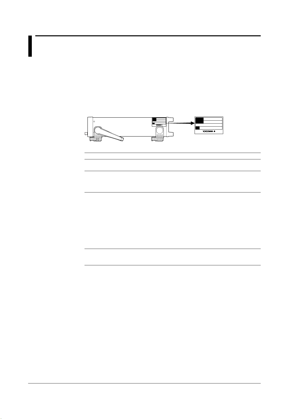
7556 Main Unit
Check that the model name and suffix code given on the name plate on the side panel
match those on the order. When contacting the dealer from which you purchased the
instrument, please quote the instrument No.
MODEL
SUFFIX
NO.
Madein Japan
MODEL and SUFFIX codes
Model Name Suffix Code Specifications
755601 0.01% resolution
755611 0.001% resolution
Power supply -1 100 VAC
-4 120 VAC
-6 220 VAC
-8 240 VAC
Power cord
Options /C1 GP-IB interface
1 Make sure that the attached power cord meets the designated standards of the country and
1
-D UL/CSA Standards Power Cord (Part No.: A1006WD)
-F VDE Standard Power Cord (Part No.: A1009WD)
-Q BS Standard Power Cord (Part No.: A1054WD)
-R SAA Standard Power Cord (Part No.: A1024WD)
-H GB Standard Power Cord (complies with the CCC)
/C2 Centronics interface
/C3 GP-IB & Centronics interface
area that you are using it in.
[Maximum Rated Voltage: 125 V, Maximum Rated Current: 7 A]
[Maximum Rated Voltage: 250 V, Maximum Rated Current: 10 A]
[Maximum Rated Voltage: 250 V, Maximum Rated Current: 10 A]
[Maximum Rated Voltage: 240 V, Maximum Rated Current: 10 A]
(Part No.: A1064WD)
[Maximum Rated Voltage: 250 V, Maximum Rated Current: 10 A]
MODEL
SUFFIX
NO.
Made in Japan
NO. (Instrument No.)
When contacting the dealer from which you purchased the instrument, please quote the
instrument No.
ii IM 755601-01E
Page 5
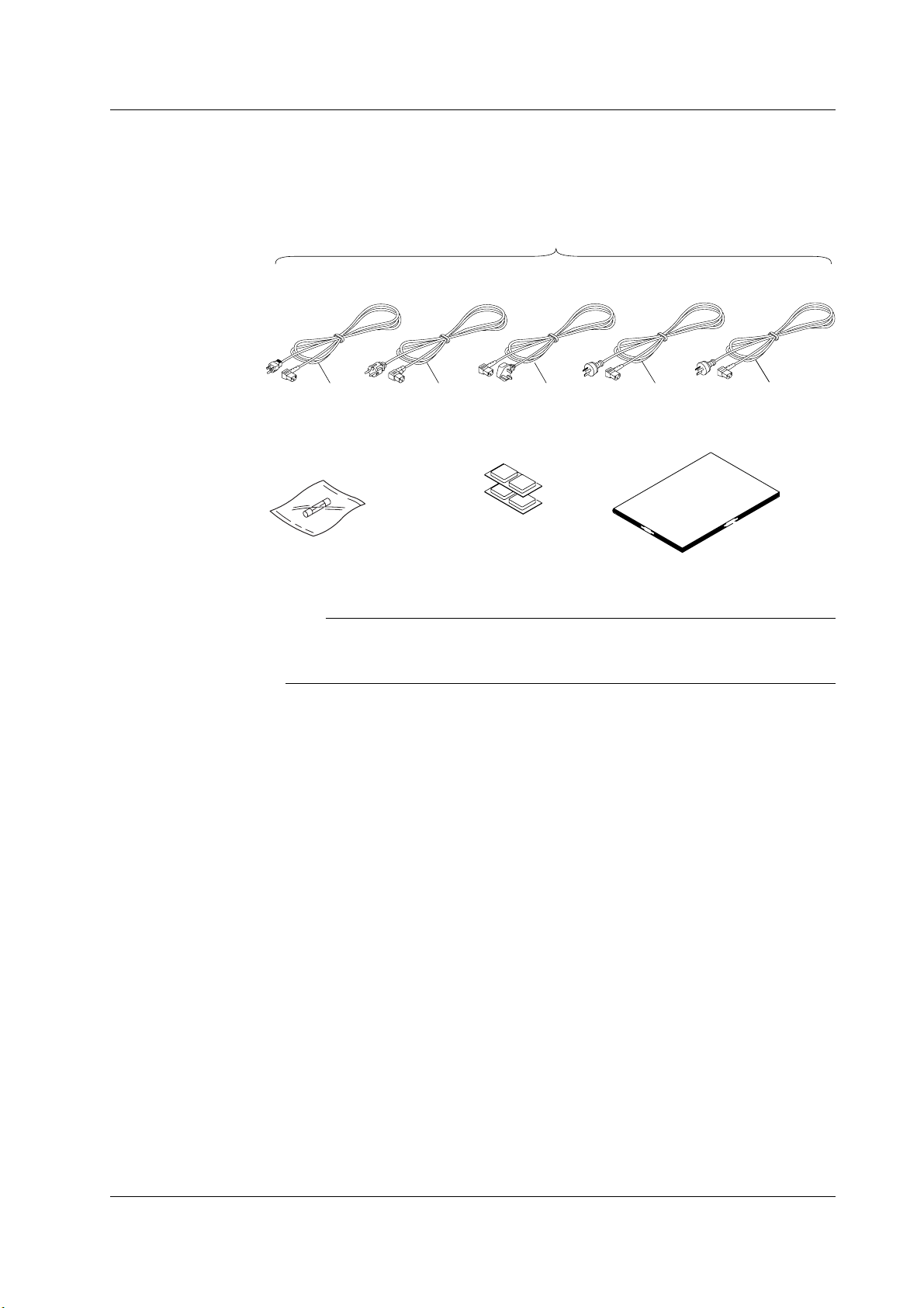
Standard Accessories
The following standard accessories are supplied with the instrument. Check that all
items are present and that they are undamaged.
Checking the Contents of the Package
1. Power cord (one of the following power cords
is supplied according to the instrument's suffix codes)
UL/CSA standard
A1006WD
D
Spare power fuse
for suffix code -1 & -4:
A1345EF (1 piece)
for suffix code -6 & -8:
A1342EF (1 piece)
1 Make sure that the attached power cord meets the designated standards of the
country and area that you are using it in.
VDE standard
A1009WD
F Q R
Rubber feet
(4 pieces)
A9088ZM 2 sets
BS standard
A1054WD
SAA standard
A1024WD
User's Manual (this manual) 1 piece
1
GB Standard
A1064WD
Note
• We recommend you keep the packing box. The box is useful when you need to transport the
instrument.
• For information regarding the fuse ratings, see section 11.5, “Replacing the Power Fuse.”
H
iiiIM 755601-01E
Page 6
Safety Precautions
This product is designed to be used by a person with specialized knowledge.
This instrument is designed for indoor use only.
The following general safety precautions must be observed during all phases of
operation. If the instrument is used in a manner not specified in this manual, the
protection provided by the instrument may be impaired.
This manual is an essential part of the product; keep it in a safe place for future
reference. YOKOGAWA assumes no liability for the customer’s failure to comply with
these requirements.
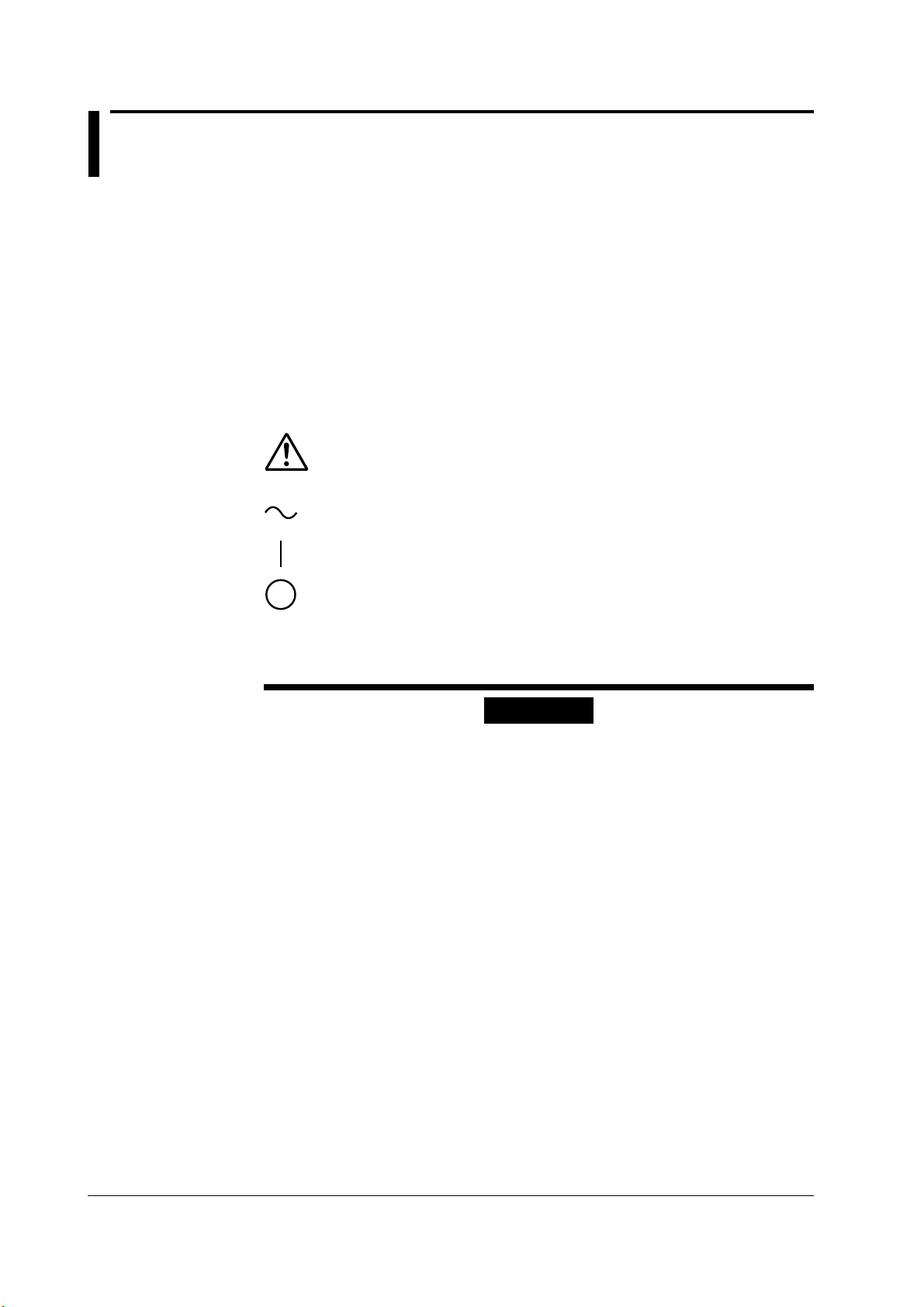
The following symbols are used on this instrument.
“Handle with care.” To avoid injury, death of personnel or damage to the
instrument, the operator must refer to the explanation in the User’s Manual or
Service Manual.
AC
ON (power)
OFF (power)
Make sure to comply with the following safety precautions. Not complying might
result in injury, death of personnel.
WARNING
Use the Instrument Only for Its Intended Purpose
This instrument is a resistance measuring device. Do not use this instrument for
anything other than as a resistance measuring device.
Check the Physical Appearance
Do not use the instrument if there is a problem with its physical appearance.
Power Supply
Ensure that the source voltage matches the voltage of the power supply before
turning ON the power.
Power Cord and Plug
• To prevent an electric shock or fire, be sure to use the power cord supplied by
YOKOGAWA. The main power plug must be plugged into an outlet with a
protective grounding terminal. Do not invalidate protection by using an extension
cord without protective grounding. Additionally, do not use the power cord
supplied with this instrument with another instrument.
• Do not use the power cord in a bundled condition.
• If you use a power plug with foreign substance on it, insulation may be
compromised by humidity or other factors and may cause a fire. Clean the
power plug regularly.
Protective Grounding
Make sure to connect the protective grounding to prevent electric shock before
turning ON the power.
iv IM 755601-01E
Page 7

Safety Precautions
Necessity of Protective Grounding
Never cut off the internal or external protective grounding wire or disconnect the
wiring of the protective grounding terminal. Doing so poses a potential shock
hazard.
Do Not Use When the Protection Functions Are Defective
Before using this instrument, check that the protection functions, such as the
protective grounding and fuse, are working properly. If you suspect a defect, do
not use the instrument.
Do Not Remove the Covers or Disassemble or Alter the Instrument
Only qualified YOKOGAWA personnel may remove the covers and disassemble
or alter the instrument. The inside of the instrument is dangerous because parts of
it have high voltages.
External Connection
Connect the protective grounding before connecting to the item under
measurement or external control circuit. If you need to touch the circuit, turn of its
power and make sure that there are no voltages being generated.
Measurement Category
The measurement category of this instrument signal input terminals is Other (O).
Do not use it to measure the main power supply or for Measurement Categories
II, III, and IV.
Install or Use the Instrument in Appropriate Locations
• This instrument is designed to be used indoors. Do not install or use it
outdoors.
• Install the instrument so that you can immediately remove the power cord if an
abnormal or dangerous condition occurs.
CAUTION
Operating Environment Limitations
This product is a Class A (for industrial environments) product. Operation of this
product in a residential area may cause radio interference in which case the user
will be required to correct the interference.
vIM 755601-01E
Page 8

Waste Electrical and Electronic Equipment
Waste Electrical and Electronic Equipment (WEEE), Directive
(This directive is valid only in the EU.)
This product complies with the WEEE directive marking requirement. This marking
indicates that you must not discard this electrical/electronic product in domestic
household waste.
Product Category
With reference to the equipment types in the WEEE directive, this product is classified as
a “Monitoring and control instruments” product.
When disposing of products in the EU, contact your local Yokogawa Europe B.V. office.
Do not dispose in domestic household waste.
EU Battery Directive
EU Battery Directive
(This directive is valid only in the EU.)
Batteries are included in this product. This marking indicates they shall be sorted out and
collected as ordained in the EU battery directive.
Battery type: Lithium battery
You cannot replace batteries by yourself. When you need to replace batteries, contact
your local Yokogawa Europe B.V. office.
vi IM 755601-01E
Page 9

How to Use this Manual
Structure of the Manual
This User’s Manual consists of the following 12 chapters, and an index.
Chapter Title Description
1 Functions Describes the measurement principles and
2 Names and Uses of Parts Describes the names and uses of each part of the
3 Before Starting Measurements Describes precautions on use, how to install the
4 Setting the Measurement Conditions Describes how to set the measurement conditions
5 Making Measurements Describes how to make measurements.
6 Other Functions Describes how to save and recall measured data
7 Using the Handler Interface Describes the handler interface specifications, how
8 Using the Serial (RS-232) Interface Describes how to control this instrument from a
9 Using the GP-IB Interface Describes how to control this instrument from a
10 Using Communication Commands Describes communication commands and sample
11 Error Messages and Maintenance, Describes the possible causes of problems and
and Inspection their appropriate corrective measures. Describes
12 Specifications The specifications of the instrument are given on
Index Gives an Index.
functions of the instrument. Operating procedures
are not given in this chapter. However, reading
this chapter will help you understand the operating
procedures given in the chapters that follow.
instrument. For keys, references are given to
pages in the manual where operating procedures
are explained.
instrument, how to connect the power supply, turn
ON/OFF the power switch, and other operations.
such as measurement range and limits.
and how to print out the data.
to setup the handler interface, and the timing chart.
controller (such as a PC) and how to retrieve
measured data from the instrument via the serial
(RS-232) interface.
controller (such as a PC) and how to retrieve
measured data from the instrument via the GP-IB
interface.
programs.
the messages that are displayed on the screen.
Describes how to perform self-tests.
tables.
viiIM 755601-01E
Page 10

How to Use this Manual
Conventions Used in this Manual
Symbols
The following symbols are used in this manual.
Affixed to the instrument. Indicates danger to personnel or
instrument and the operator must refer to the User’s Manual. The
symbol is used in the User’s Manual to indicate the reference.
WARNING
CAUTION
Note
Characters displayed on the seven-segment LED
Because this instrument uses a seven-segment LED to display alphanumeric characters,
some of the characters are displayed using special characters. For details, see section
1.3, “Digital Numbers and Characters and A List of Menus” (page 1-4).
Symbols used on pages in which operating procedures are given
In chapters 3 through 9, on pages where operating procedures are given, the following
symbols are used to classify a description.
Keys
Procedure
Describes precautions that should be observed to prevent injury
or death to the user.
Describes precautions that should be observed to prevent minor
or moderate injury, or damage to the instrument.
Provides important information for the proper operation of the
instrument.
Indicates the keys and indicators related to the setting.
Describes the procedures using a flow diagram. For details on how
to read the flow diagram, see the example given on the next page.
The procedures are based on the premise that the user is carrying
them out for the first time. Therefore, in some cases, you may not
have to follow all the steps.
Explanation
viii IM 755601-01E
Describes the details of the settings and the restrictions that exist
with the operating procedure. A detailed description of the function
is not provided in this section. See chapter 1 for a detailed
description of the functions.
Page 11

How to Use this Manual
A Procedure Example
1. Pressing the SHIFT key then the MΩ key displays the contact check selection
menu.
2. Press the
REF
LIMIT
or
<
key until the desired item appears on the screen.
>
3. Press the ENTER key to confirm the selection.
4. If you selected bEF or AFt, enter the contact check level using the numerical keys.
Then, press the ENTER key to confirm.
1.
SHIFT
M
Ω
CHECK
2.
REF LIMIT
3.
Ω
,%
ENTER
Ω
,%
ENTER
(Contact check level)
4.
Ω
ENTER
,%
Symbols Used in the Syntax
The following table indicates symbols that are used in the syntax mainly in Chapter 10.
These symbols are referred to as BNF (Backus-Naur Form) symbols. For details, see
pages 10-5 and 10-6.
Symbol Meaning Example User Input Example
<> Defined value :PANel:RECall{<NRf>}<NRf>=0 to 9 →:PANEL:RECALL 3
{} Select a value from {} :MTIMe{NORMal|FAST|HSPeed} →:MTIME FAST
| Exclusive OR
[] Can be omitted :CHECK[:MODE]BEFore →:CHECK:BEFORE
ixIM 755601-01E
Page 12

Contents
Checking the Contents of the Package .........................................................................................ii
Safety Precautions .......................................................................................................................iv
Waste Electrical and Electronic Equipment ................................................................................. vi
EU Battery Directive .....................................................................................................................vi
How to Use this Manual .............................................................................................................. vii
Chapter 1 Functions
1.1 Block Diagram ........................................................................................................................... 1-1
1.2 Functions .................................................................................................................................. 1-2
1.3 Digital Numbers and Characters and A List of Menus .............................................................. 1-4
1.4 A List of Initial Values ................................................................................................................ 1-7
Chapter 2 Names and Uses of Parts
2.1 Names of Parts ......................................................................................................................... 2-1
2.2 Keys and Error Displays ........................................................................................................... 2-2
Chapter 3 Before Starting Measurements
3.1 Precautions on the Use of the instrument ................................................................................. 3-1
3.2 Installing the Instrument ............................................................................................................ 3-2
3.3 Connecting the Power Cord ...................................................................................................... 3-3
3.4 Wiring ........................................................................................................................................ 3-5
Chapter 4 Setting the Measurement Conditions
4.1 Switching the Limit Mode .......................................................................................................... 4-1
4.2 Changing the Range (Reference) ............................................................................................. 4-2
4.3 Using the Comparator Function ................................................................................................ 4-4
4.4 Using the Contact Check Function ........................................................................................... 4-7
4.5 Setting the Measurement Time ................................................................................................. 4-8
4.6 Using the Trigger Function ........................................................................................................ 4-9
Chapter 5 Making Measurements
5.1 Setting the Measurement Mode ................................................................................................ 5-1
5.2 Switching between Deviation (%) and Absolute (R) Displays ................................................... 5-3
Chapter 6 Other Functions
6.1 Store/Recall Measured Data ..................................................................................................... 6-1
6.2 Printing Data ............................................................................................................................. 6-3
6.3 Initializing the Setup Information ............................................................................................... 6-7
Chapter 7 Using the Handler Interface
7.1 Handler Interface Functions and Specifications ........................................................................ 7-1
7.2 Setting the Pulse Width of the EOM Signal .............................................................................. 7-4
7.3 Timing Chart.............................................................................................................................. 7-5
x IM 755601-01E
Page 13

Contents
Chapter 8 Using the Serial (RS-232) Interface
8.1 Serial (RS-232) Interface Functions and Specifications ........................................................... 8-1
8.2 Connecting the Serial (RS-232) Interface Cable ....................................................................... 8-2
8.3 Handshaking ............................................................................................................................. 8-4
8.4 Data Format .............................................................................................................................. 8-6
8.5 Serial Communication Settings ................................................................................................. 8-7
Chapter 9 Using the GP-IB Interface
9.1 GP-IB Interface Functions and Specifications .......................................................................... 9-1
9.2 Connecting the Interface Cable ................................................................................................ 9-3
9.3 Responses to Interface Messages ............................................................................................ 9-4
9.4 Switching to the Addressable Mode .......................................................................................... 9-6
9.5 Switching to the Talk-only Mode................................................................................................ 9-8
Chapter 10 Communication Commands
10.1 Before Programming ............................................................................................................... 10-1
10.1.1 Messages...................................................................................................................................... 10-1
10.1.2 Commands.................................................................................................................................... 10-3
10.1.3 Responses .................................................................................................................................... 10-4
10.1.4 Data .............................................................................................................................................. 10-5
10.1.5 Synchronization with the Controller .............................................................................................. 10-7
10.1.6 Programming of Various Functions ............................................................................................... 10-9
10.2 Commands ............................................................................................................................ 10-13
10.2.1 A List of Commands .................................................................................................................... 10-13
10.2.2 CHECk(contact CHECk) Group .................................................................................................. 10-15
10.2.3 COMMunicate Group .................................................................................................................. 10-16
10.2.5 HANDler Group ........................................................................................................................... 10-18
10.2.4 DISPlay Group ............................................................................................................................ 10-18
10.2.6 HEADer Group ............................................................................................................................ 10-19
10.2.7 LIMit Group ................................................................................................................................. 10-20
10.2.8 MEASure Group.......................................................................................................................... 10-22
10.2.9 MTIMe(Meas TIMe) Group.......................................................................................................... 10-23
10.2.10 PANel Group ............................................................................................................................... 10-23
10.2.11 PRINt Group (Option) ................................................................................................................. 10-24
10.2.12 READ Group ............................................................................................................................... 10-25
10.2.13 RECall Group .............................................................................................................................. 10-26
10.2.14 SELFtest Group .......................................................................................................................... 10-28
10.2.15 STATus Group ............................................................................................................................. 10-29
10.2.16 STORe Group ............................................................................................................................. 10-30
10.2.17 TRIGger Group ........................................................................................................................... 10-32
10.2.18 Common Command Group ......................................................................................................... 10-33
10.3 Status Report ........................................................................................................................ 10-36
10.3.1 About the Status Report.............................................................................................................. 10-36
10.3.2 Status Byte.................................................................................................................................. 10-37
10.3.3 Standard event register............................................................................................................... 10-38
10.3.4 Extended Event Register ............................................................................................................ 10-39
10.3.5 Output Queue and Error Queue.................................................................................................. 10-40
10.4 ASCII Character Codes ........................................................................................................ 10-41
10.5 About the IEEE.488.2-1992 Standard ................................................................................... 10-42
1
2
3
4
5
6
7
8
9
10
11
12
Index
xiIM 755601-01E
Page 14

Contents
Chapter 11 Error Messages, Maintenance, and Inspection
11.1 Troubleshooting ...................................................................................................................... 11-1
11.2 Messages and Corrective Actions........................................................................................... 11-2
11.3 Self Test .................................................................................................................................. 11-5
11.4 Adjustments ............................................................................................................................ 11-7
11.5 Replacing the Power Fuse ....................................................................................................11-12
Chapter 12 Specifications
12.1 Input Specifications ................................................................................................................. 12-1
12.2 Trigger Specifications.............................................................................................................. 12-3
12.3 Measurement Time Specifications .......................................................................................... 12-3
12.4 Contact Check Specifications ................................................................................................. 12-4
12.5 Comparator Specifications ...................................................................................................... 12-4
12.6 Other Specifications ................................................................................................................ 12-5
12.7 Handler Interface Specifications ............................................................................................. 12-5
12.8 Communication Specifications ................................................................................................ 12-6
12.9 General Specifications ............................................................................................................ 12-6
12.10 External Dimensions ............................................................................................................... 12-8
Index
xii IM 755601-01E
Page 15
Chapter 1 Functions
LOCAL key
GP-IB connector
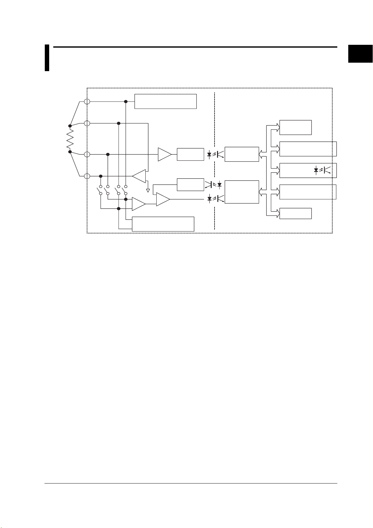
1.1 Block Diagram
Block Diagram
H
L
H
L
CUR
POT
POT
CUR
Constant current source
for measurement
-
+
Diff. amp.
Constant current source
for contact check
Analog section Digital section
A/D
converter
Pre-amp
D/A
converter
Comparator
A/D
interface
CPU
1
Functions
Display
interface
Printer
interface
Handler
interface
Communication
interface
Memory
Measurement Principle
A constant current is fed through the resistor under measurement from the H
to the L
measured. Because the electric potential at the H
equal to the circuit’s common electric potential, the resistance can be determined by
dividing the voltage at the L
In the contact check that is performed before or after the measurement, a constant
current is fed from the H
the L
reference voltage that was set by the D/A converter to check the connection to the
resistor under measurement.
Since the analog section is insulated from the digital section (electric potential of the
case), the circuit is robust against noise, resulting in a stable measurement. In addition,
the handler interface is also insulated from the case in order to minimize noise influence.
CUR
terminal, and the voltage difference between the H
CUR
terminal is controlled so that it is
POT
terminal by the current.
POT
terminal to the H
CUR
terminal. The voltage that appears across these terminals is compared with the
CUR
terminal and from the L
POT
POT
and L
terminals is
POT
terminal to
POT
terminal
1-1IM 755601-01E
Page 16

1.2 Functions
Comparator Function
Determines whether or not the measured result is within the comparison range set
arbitrarily by the user. HI, IN, or LO mark is turned ON to indicate the comparator result.
The result is also output via the handler interface.
Contact Check Function
Determines whether or not the item under measurement is properly connected to the
measurement input terminal, and the result is output via the handler interface. If an error
is detected, “ (no contact)” is displayed.
Trigger Function
Trigger Mode
The instrument has the following three types of trigger modes:
• External trigger: Makes a measurement when the instrument detects a rising or
• Manual trigger: Makes a measurement when the TRIG key on the front panel is
• Internal trigger: Makes measurements at intervals which depend on the specified
falling edge of a signal that is applied to the external trigger input
terminal or the number 8 pin (EXT TRIG) of the handler interface.
pressed or whenever a trigger is activated via the communication
interface.
measurement time (auto sampling).
Trigger Delay
The measurement can then be started the specified time after the trigger occurrence. A
trigger delay is enabled when the trigger mode is set to external trigger or manual trigger.
Communication Function
Handler and serial (RS-232) interfaces come standard with the instrument. A GP-IB
interface is also available as an option.
Printout Function
By using the optional Centronics interface, data stored in the memory, statistics collected
from those data, and other information can be printed to an external printer.
1-2 IM 755601-01E
Page 17

1.2 Functions
Handler Interface Function
The handler interface is used to output comparator results, contact check results, index
signals, and various other signals.
For the specifications of each pin, see section 12.7 “Handler Interface Specifications.”
Other Functions
Storing/Recalling Measured Data
Up to 2000 data sets can be stored. Each data set contains the measured value
obtained from each measurement.
A data set is stored or recalled at every trigger occurrence.
Initializing settings
The settings can be reset to factory default values or initial values.
Measurement Mode/SETUP mode
The instrument has two modes, measurement and SETUP modes. You can switch
between the modes as necessary.
Measurement mode: This mode measures and displays the resistance. Only the R/%
SETUP mode: This mode is used to change the instrument’s settings. No
1
Functions
key, SETUP/MEAS key (SHIFT+R/% key), and STORE DATA
key (SHIFT+0 key) are enabled. Since all other keys are locked,
an erroneous operation resulting from pressing the wrong keys
can be avoided.
However, the TRIG key is enabled when the trigger mode is set
to [MANUAL] and the RECALL DATA key is enabled when
recalling data.
measurements can be made in this mode.
Limit Mode (Deviation/Absolute)
You can select whether to use a deviation (%) or an absolute value (R) to specify the
limit value (LO, HI) that is used when determining the result with the comparator function.
The comparator determines the result using deviation (%) if you set the limit mode to
deviation. The measured value can then be displayed using % or Ω.
The comparator determines the result using absolute value (R) if you set the limit mode
to absolute mode (R). The measured value is displayed using Ω. In this mode, the
comparator function works only for the 1 Ω range.
1-3IM 755601-01E
Page 18
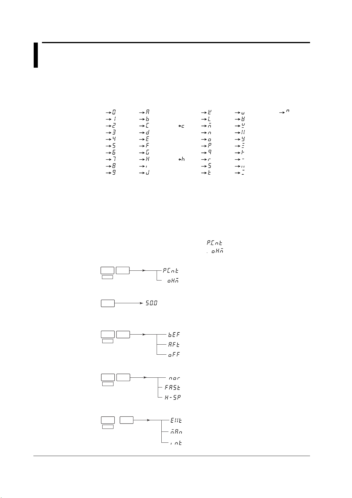
1.3 Digital Numbers and Characters and A List of Menus
Digital Numbers and Characters
Because the instrument’s display is a seven-segment LED, the following special
characters are used to represent the alphanumeric characters. Some characters are not
used by the instrument.
A List of Menus
0
1
2
3
4
5
6
7
8
9
A
B
C
D
E
F
G
H
I
J
Lower case c
Lower case h
K
L
M
N
O
P
Q
R
S
T
U
V
W
X
Y
Z
+
–
×
÷
∧ (power)
In this section, a list of menus for the SETUP mode is given for each operation key.
For information regarding the EXIT and < , > keys, see section 2.2, “Keys and Error Displays.”
Top menu of the SETUP mode
The first menu displayed in the main display in the SETUP mode is called the top menu.
The display returns to this menu when you confirm a setting or when you exit from a menu.
The top menu varies depending on the limit mode setting as follows:
When the limit mode is set to % (PCnt) :
When the limit mode is set to R (OHm) :
Limit mode setting menu (page 4-1)
SHIFT
8
LIMIT
MODE
(Deviation mode)
(Absolute mode)
Reference setting menu (page 4-2)
REF
(Set the reference)
Contact check setting menu (page 4-7)
M
SHIFT
Ω
CHECK
(Execute before measurement)
(Execute after measurement)
(Disable contact check)
Measurement time selection menu (page 4-8)
SHIFT
7
MEAS
TIME
(Normal)
(Fast)
(High speed)
Trigger mode setting menu (page 4-9)
SHIFT
TRIG
TRIG
MODE
(External trigger)
(Manual trigger)
(Internal trigger)
1-4 IM 755601-01E
Page 19
1.3 Digital Numbers and Characters and A List of Menus
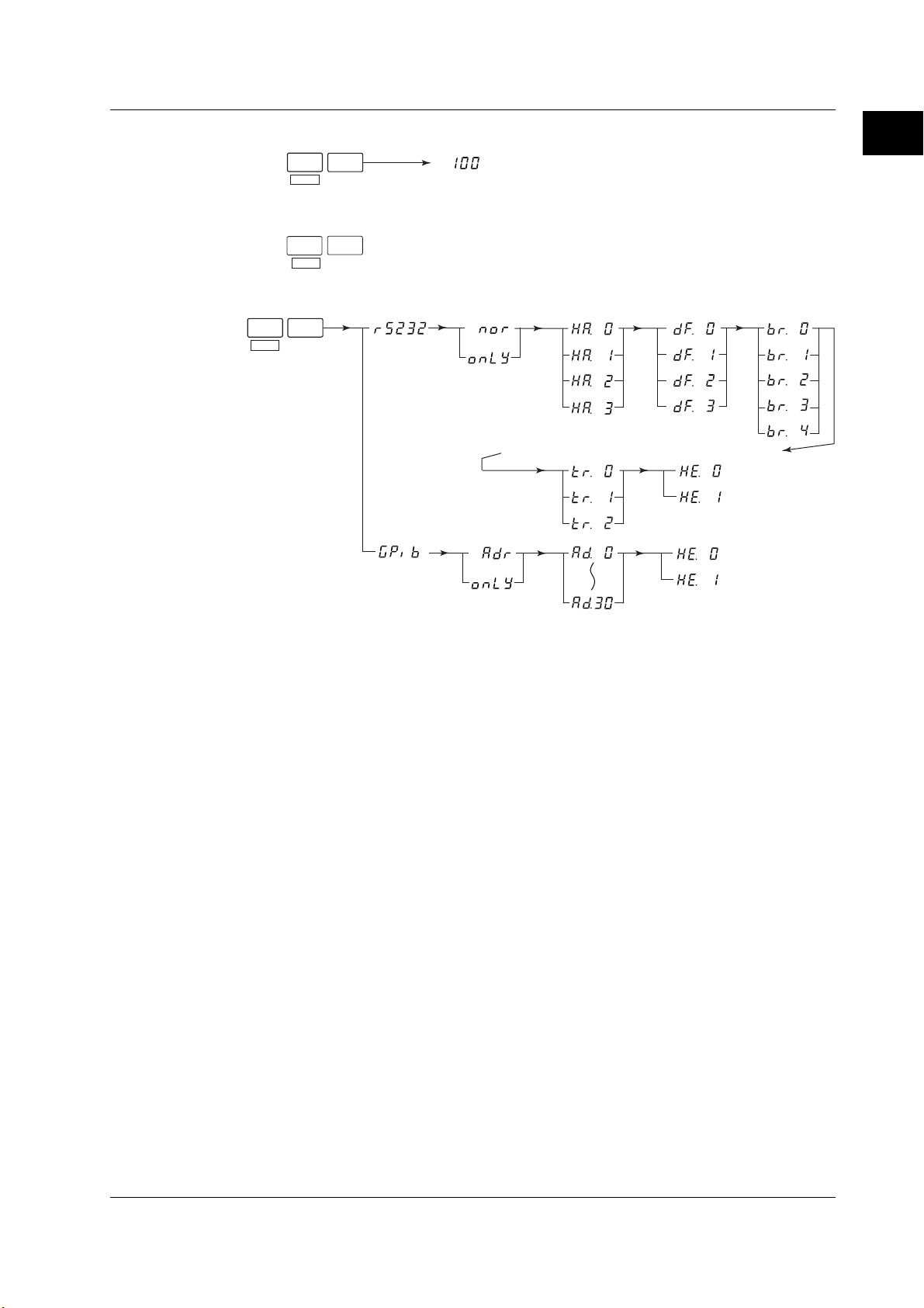
Measured data store menu (page 6-1)
0
STORE
SHIFT
DATA
(Number of stored data sets)
Measured data recall menu (page 6-1)
.
RECALL
SHIFT
DATA
Communication interface setting menu (page 8-7 and 9-6)
3
SHIFT
I/F
*
1
Functions
* Displayed only on instruments that have the optional GP-IB interface.
1-5IM 755601-01E
Page 20

1.3 Digital Numbers and Characters and A List of Menus
Misc menu (pages 4-5, 4-10, 4-11, 6-3, 6-4, 6-7, 7-4, and 11-6)
1
*
1
*
SHIFT
k
MISC
Ω
(Printer output)
(Output format)
(Start printing)
(Stop printing)
(40 characters, no measured data)
(40 characters, with measured data)
(A4 size, no measured data)
(A4 size, with measured data)
2
*
(Percent limit)
(Trigger delay)
(Trigger edge)
(EOM pulse width)
(Initialize setup information)
(Self-test)
3
*
3
*
(Delay time in units of ms)
(Rising)
(Falling)
(in units of ms)
*1 Displayed on instruments that have the optional Centronics interface.
*2 Not displayed when the limit mode is set to absolute mode (R).
*3 For the 755611. “9.99” or “99.9” is displayed on the 755601.
1-6 IM 755601-01E
Page 21

1.4 A List of Initial Values
Parameter Factory Default Initial Settings Resume Function*
Display Deviation Deviation Yes
Deviation reference (REF) 100 kΩ 100 kΩ Yes
Measurement time NORMAL NORMAL Yes
Trigger mode EXTERNAL EXTERNAL Yes
Trigger delay 0 ms 0 ms Yes
Contact check function ON ON Yes
Contact check timing Before Before Yes
Contact check level 30 Ω 30 Ω Yes
HI limit 0% 0% Yes
LO limit 0% 0% Yes
Measured data store OFF OFF No
Number of stored data 100 100 Yes
Contents of the stored data Cleared Cleared No
Measured data recall OFF OFF No
SETUP/MEAS SETUP SETUP Yes
Limit mode PCNT PCNT Yes
Percent limit 9.99 9.99 Yes
EOM width 10 ms 10 ms Yes
Communication interface Serial (RS232) Previous condition Yes
Serial (RS232)
Mode Normal Previous condition Yes
Handshaking 0 Previous condition Yes
Data format 0 Previous condition Yes
Baud rate 3 Previous condition Yes
Terminator 0 Previous condition Yes
Header 0 Previous condition Yes
GP-IB
Mode Addressable Previous condition Yes
Address 1 Previous condition Yes
Header 0 Previous condition Yes
Printer (option) OFF OFF No
Print out of measured data OFF.rP OFF.rP Yes
Yes: enabled, No: disabled
* Resume function: A function in which the setup information is stored when the power is turned
OFF and recalled when it is turned ON again.
1
Functions
1-7IM 755601-01E
Page 22
LOCAL key
GP-IB connector
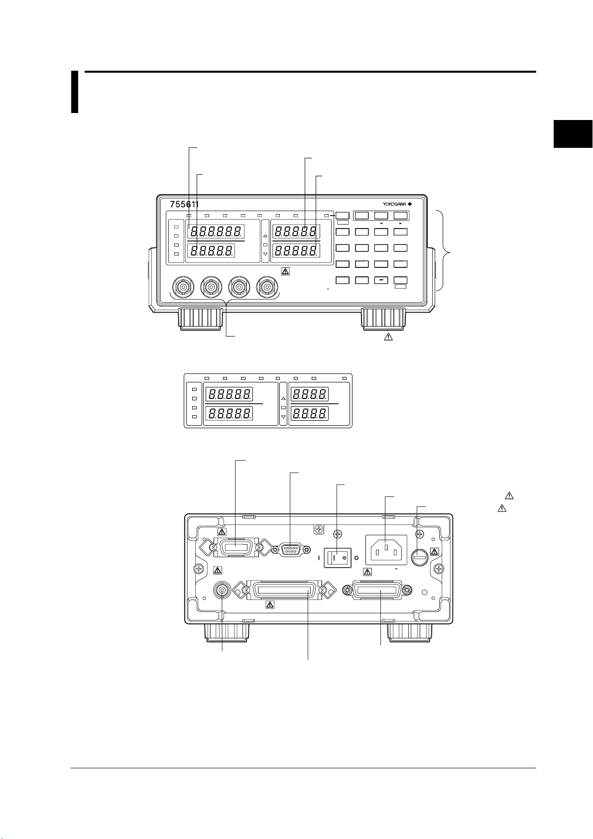
Chapter 2 Names and Uses of Parts
2.1 Names of Parts
Front Panel
Setting value/setting display (Main display, 5 digits on the 755601)
Reference display
DIGITAL RESISTANCE METER
HIGH
STORE
NORMAL
FAST
REFERENCE
UNKNOWN
SPEED
MEAS&
LOCK
SAMPLE
EXTERNAL
MANUAL
L
CUR L POT H POT H CUR
RECALL
DATA
DATA
HI
%
IN
MΩ
LO
kΩ
Ω
Measurement input terminal (page 3-5)
755601 Display Screen
HIGH
MEAS&
LOCK
SAMPLE
EXTERNAL
MANUAL
NORMAL
FAST
REFERENCE
SPEED
STORE
DATA
MΩ
kΩ
CHECK REMOTE
HI LIMIT
LO LIMIT
Do not connect a current/voltage
source to the UNKNOWN terminals.
It will damage the instrument.
ALL TERMINALS 42 V PEAK TO
RECALL
CHECK REMOTE
DATA
HI
%
IN
LO
Ω
HI LIMIT display (4 digits on the 755601)
LO LIMIT display (4 digits on the 755601)
SETUP/MEAS
REF LIMIT
R/%
SHIFT
HI LIMIT
LO LIMIT
EXIT
89
7
%
MEAS
LIMIT
TIME
Ω
MODE
546
1
23
.
0
STORE
RECALL
DATA
DATA
%
Ω
LOCAL
TRIG
TRIG
MODE
M
CHECK
MISCI/F
Ω,%
ENTER
Ω
k
Ω
2
Names and Uses of Parts
Numerical key/
setting key (page 2-2)
Rear Panel (for both 755601, 755611)
Handler interface connector (page 7-3)
HANDLER
TRIGGER IN
External trigger input
terminal (page 4-11)
Serial (RS-232) interface connector (chapter 8)
Power switch (page 3-4)
Power connector (page 3-3)
SERIAL
PRINTER
(RS-232)
POWER
ON
OFF
100V AC
25VA MAX
50/60Hz
GP-IB(IEEE488)
FUSE
250V T 315mA
GP-IB interface connector (chapter 9)
Centronics interface connector (page 6-4)
Fuse (page 11-12)
2-1IM 755601-01E
Page 23

2.2 Keys and Error Displays
Display
The selected measurement time lights
Lights while storing measured data
Lights while recalling measured data
Indicates the comparator result
Lights during contact check
Lights while operating under remote control
HIGH
STORE
RECALL
NORMAL
FAST
SPEED
MEAS&
LOCK
SAMPLE
EXTERNAL
MANUAL
REFERENCE
DATA
%
MΩ
kΩ
Ω
Lights when the trigger mode is set to MANUAL
Lights when the trigger mode is set to EXTERNAL
Lights every data sample
Lights during measurement mode
Switching between measurement mode and SETUP mode
SETUP/MEAS (SHIFT+R/%) key
This key is used to switch between measurement mode and SETUP mode. The
instrument is in the measurement mode when the “MEAS & LOCK” indicator is lit.
DATA
HI
IN
LO
CHECK REMOTE
HI LIMIT
LO LIMIT
SETUP/MEAS
SHIFT
7
%
MEAS
TIME
Ω
1
0
STORE
DATA
REF LIMIT
R/%
EXIT
LOCAL
TRIG
TRIG
MODE
M
CHECK
k
MISCI/F
,%
Ω
ENTER
Ω
Ω
89
LIMIT
MODE
546
23
.
RECALL
DATA
Keys used during the measurement mode
R/% key
This key is used to switch the unit between absolute (R) and deviation (%) in which the
measured value is displayed. When the limit mode is set to absolute (R), pressing this
key will have no effect.
2-2 IM 755601-01E
Page 24

Keys used during the SETUP mode
SHIFT key
Pressing this key once causes the keys to enter the shifted condition. Pressing it again
clears the shifted condition. During the shifted condition, the functions indicated in
purple characters are effective. The shifted condition is indicated by a lit indicator to the
left of the SHIFT key.
EXIT(R/%) key
Used to cancel the setting operation. Pressing this key cancels the specified settings
and causes the instrument to return to the top menu of the SETUP mode.
REF key
When the limit mode is set to deviation (%), this key is used to set the range (reference).
LIMIT key
Used to set the upper and lower limits.
<(REF) key
• When entering numbers (using the numerical keys), this key operates as a backspace
key.
• This key is also used when selecting a parameter in the SETUP menu.
>(LIMIT) key
• When entering numbers, this key operates as a clear key.
• It is also used when selecting a parameter in the SETUP menu.
Numerical keys
• Used when entering numerical values. These keys are valid only when entering
numbers.
• The MΩ, kΩ, Ω, and % keys are used to set a unit on the numerical value.
TRIG key
When the trigger mode is set to manual trigger, pressing this key activates a trigger.
MEAS TIME(SHIFT+7) key
Used to select the measurement time.
LIMIT MODE(SHIFT+8) key
Used to select the limit mode between deviation (%) and absolute (R).
CHECK(SHIFT+MW) key
Used to set the contact check function.
I/F(SHIFT+3) key
Used to set the serial (RS-232) interface or the optional GP-IB interface.
MISC(SHIFT+kW) key
Used to set the trigger delay and other parameters.
STORE DATA(SHIFT+0) key
Used when storing the measured data.
RECALL DATA(SHIFT+ .) key
Used when recalling the measured data.
LOCAL key
Clears the remote mode.
ENTER(Ω,%) key
Used to confirm a specified value or parameter.
2.2 Keys and Error Displays
2
Names and Uses of Parts
2-3IM 755601-01E
Page 25
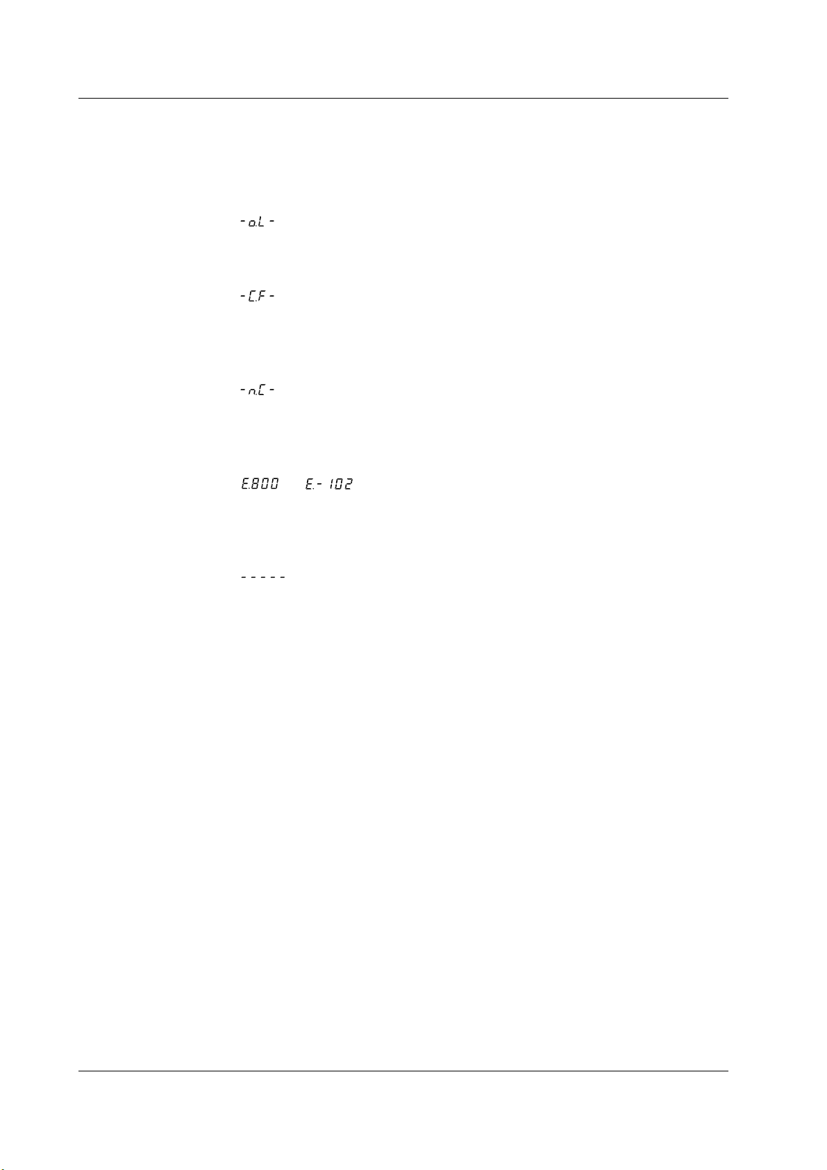
2.2 Keys and Error Displays
Error Display
Overrange display
When the measured value exceeds the display range or the maximum display value for
the corresponding measurement range, an overrange results. The display shows the
following when the measured value is over the range.
“ ”
Display when an abnormality is detected in the test current
The display when an abnormality is detected in the test current shows the following:
“ ”
Contact check error display
When using the contact check function to make measurements, the display shows the
following when a contact check error occurs.
“
Other error displays
When an error that is described in section 11.2 “Messages and Corrective Actions”
occurs, the corresponding error code is displayed as follows:
“
”
” or “ ”
Bar Display
When the mode is switched from the SETUP mode to the measurement mode, the
display shows the following until the first measured value is displayed.
“
”
2-4 IM 755601-01E
Page 26
Chapter 3 Before Starting Measurements
3.1 Precautions on the Use of the instrument
Safety Precautions
If you are using this instrument for the first time, make sure to thoroughly read the
“Safety Precautions” given on page iii.
• Do not remove the cover from the instrument. Some sections inside the instrument
have high voltages that are extremely dangerous. For internal inspection or
adjustment, contact your nearest YOKOGAWA dealer as listed on the back cover of
this manual.
• Never continue to use the instrument if there are any symptoms of trouble such as
strange smells or smoke coming from the instrument. In such cases, immediately turn
OFF the power and unplug the power cord. Then, contact your nearest YOKOGAWA
dealer as listed on the back cover of this manual.
• Nothing should be placed on top of the power cord. The power cord should also be
kept away from any heat sources. When unplugging the power cord from the outlet,
never pull the cord itself. Always hold the plug and pull it. If the power cord is
damaged, contact your dealer for replacement. Refer to page ii for the part number
when placing an order.
General Handling Precautions
• Never place any objects containing water on top of the instrument. This may cause problems.
• Do not apply shock to the input section. Applying shock to the input terminal or the
probe can cause electrical noise to enter the instrument.
• When the instrument is not being used for an extended period of time, unplug the
power cord from the outlet.
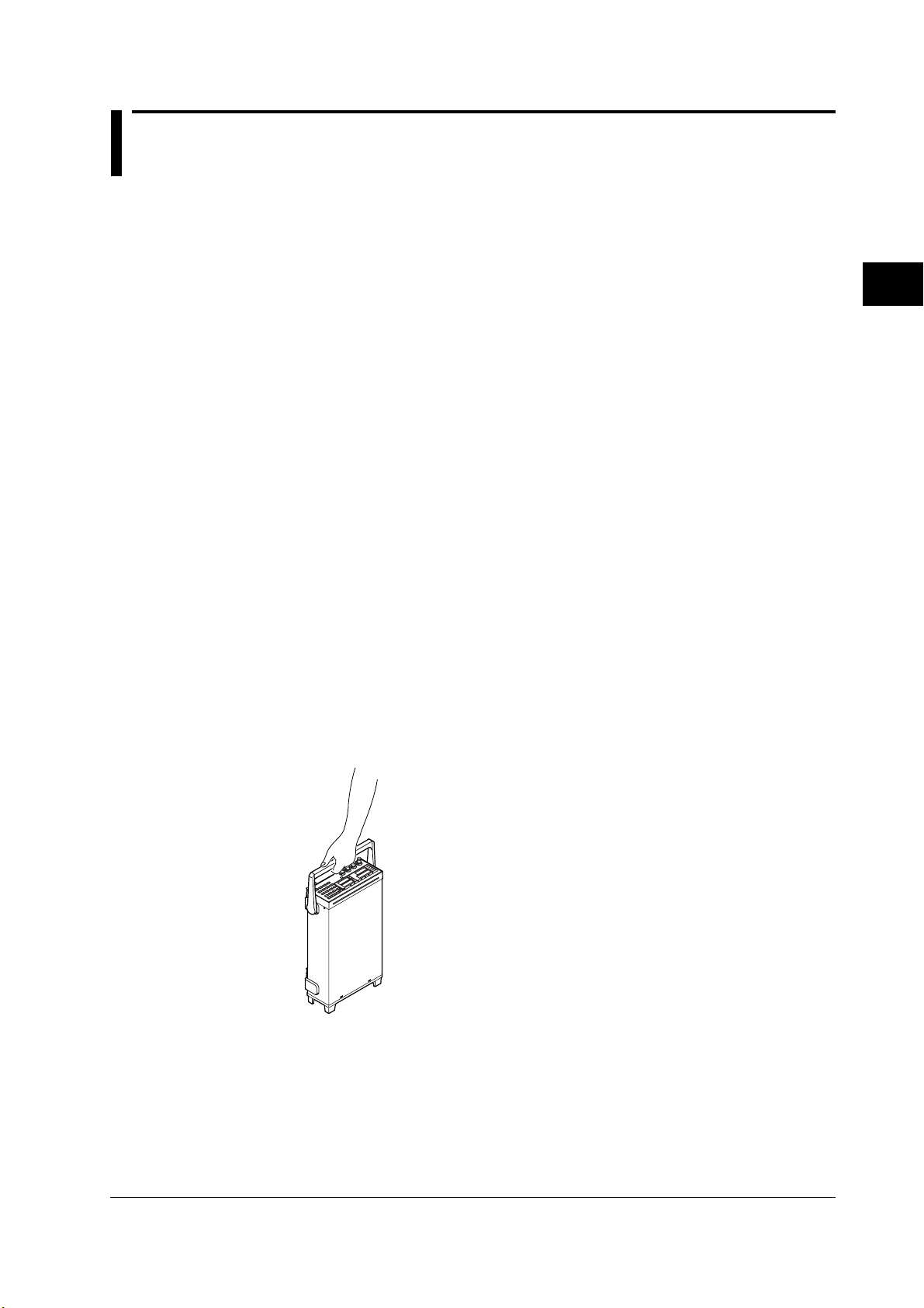
• When moving the instrument, first, turn OFF the devices under measurement and
remove all measurement wires and communication cables. Then, turn OFF the
instrument and remove the power cord from the outlet. To carry the instrument, use
the handle (see figure below) or carry it using both hands.
3
Before Starting Measurements
• Keep electrically charged objects away from the input terminals. They may damage
the internal circuitry.
• Do not pour volatile agents on the case nor leave the case in contact with rubber or
PVC products for long periods of time. The case is made of a thermoplastic resin, so
take care not to let anything hot such as a soldering iron touch the case.
• When cleaning the case or the operation panel, remove the instrument’s power cord
from the outlet. Then, wipe with a dry, soft cloth. Do not use volatile chemicals since
this might cause discoloring and deformation.
3-1IM 755601-01E
Page 27
3.2 Installing the Instrument
Installation condition
Install the instrument in a place that meets the following conditions.
Flat, even surface
Install the instrument on a stable horizontal surface. Otherwise, precise measurements
may be impeded.
Ambient temperature and humidity
Ambient temperature: 5 to 40°C
Ambient humidity: 20 to 80%RH (no condensation)
Do not install the instrument in the following places:
• Outdoor.
• In direct sunlight or near heat sources.
• Where an excessive amount of soot, steam, dust, or corrosive gases are present.
• Where the instrument is exposed to water or other liquids.
• Near strong magnetic field sources.
• Near high voltage equipment or power lines.
• Where the level of mechanical vibration is high.
• In an unstable place.
• In a place where the power switch cannot be accessed easily.
Note
• For the most accurate measurements, use the instrument in the following environment.
Ambient temperature: 23±3°C, ambient humidity: 30 to 75%RH (no condensation)
When using the instrument in a place where the ambient temperature is 5 to 18°C or 28 to
40°C, add the temperature coefficient to the accuracy of the module as specified in chapter
12, “Specifications.”
• When installing the instrument in a place where the ambient humidity is 30% or below, take
measures to prevent static electricity such as using an anti-static mat.
• Internal condensation may occur if the instrument is moved to another place where both the
ambient temperature and humidity are higher, or if the temperature changes rapidly. In this
case, let the instrument adjust to the new environment for at least one hour before using the
instrument. Check to see that there is no condensation.
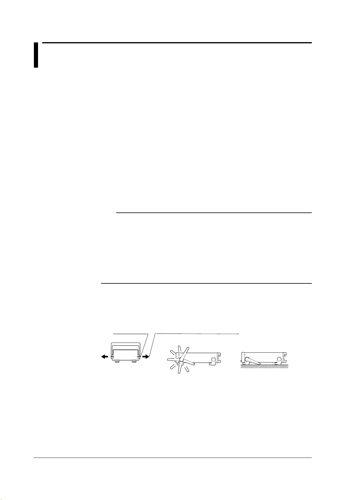
Installation position
Place the instrument on a flat, even surface as shown in the figure below. To adjust the
handle position, pull the handle outward on each side along the axis of rotation by 2 to 3
mm, then slowly rotate the handle to another locked position.
Axis of rotation
Pull the handle outward on each side
by 2 to 3 mm and rotate.
7
Locked positions of the handle
6
5
4
8
1
2
3
1
Storage Location
Do not store the instrument in the following kinds of places:
• Where the relative humidity is 80% or higher or where the temperature is 60°C or
higher
• In direct sunlight or near heat sources
• Where an excessive amount of dust, salt, or iron is present
• Where there are corrosive or explosive gases
• Where water, oil, or chemicals may splash
• Where the level of mechanical vibration is high
We recommend that the instrument be stored in an environment where the temperature
is between 5 and 40°C and the relative humidity is between 20 and 80% RH.
3-2 IM 755601-01E
Page 28
3.3 Connecting the Power Cord
Before connecting the power
Follow the warnings below to avoid electric shock and damage to the instrument.
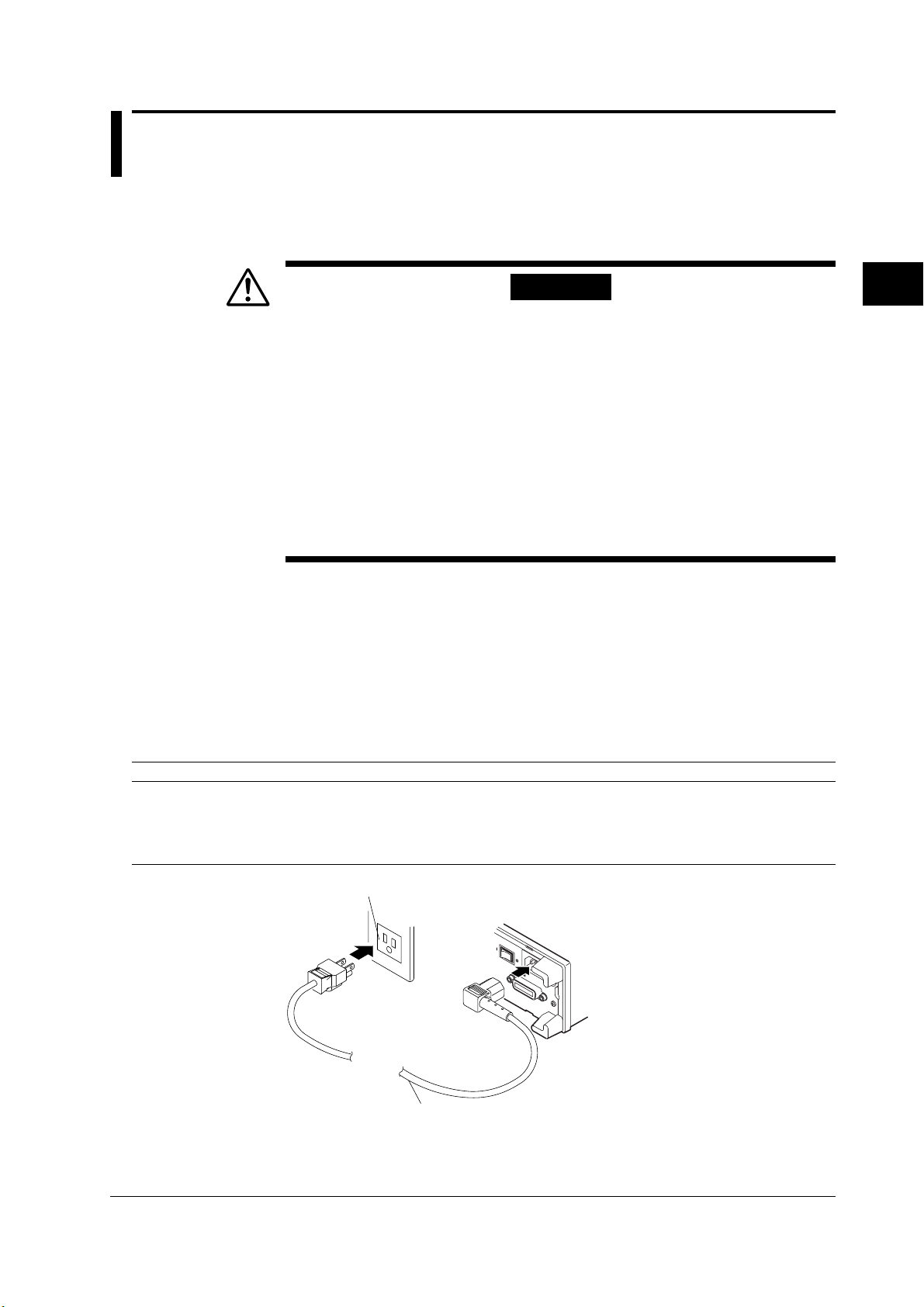
Connecting Procedure
1. Check that the power switch on the rear panel is OFF.
2. Connect the plug of the power cord that is included in the package to the power
3. Plug the other end of the power cord into a power outlet that satisfies the conditions
WARNING
• Connect the power cord only after confirming that the voltage of the
power supply matches the rated electric power voltage for the
instrument.
• Connect the power cord after checking that the power switch of the
instrument is turned OFF.
• To prevent electric shock or fire, always use the power cord supplied by
YOKOGAWA.
• Always use protective grounding to prevent electric shock. Connect the
power cord of the instrument to a three-pole power outlet that has a
protective grounding terminal.
• Never use an extension cord that does not have protective grounding,
otherwise the protection function will be compromised.
connector on the rear panel of the instrument.
below. The AC outlet must be a three-pole type that has a protective grounding
terminal.
3
Before Starting Measurements
Item Suffix Code -1 Suffix Code -4 Suffix Code -6 Suffix Code -8
Rated supply voltage 100 VAC 120 VAC 220 VAC 240 VAC
Permitted supply voltage range 90 to 110 VAC 108 to 132 VAC 198 to 242 VAC 216 to 264 VAC
Rated supply voltage frequency 50/60 Hz 50/60 Hz 50/60 Hz 50/60 Hz
Permitted supply voltage frequency range 47 to 66 Hz 47 to 66 Hz 47 to 66 Hz 47 to 66 Hz
Maximum power consumption 25 VA 25 VA 25 VA 25 VA
Three-pole outlet
Power cord
(Standard accessory)
3-3IM 755601-01E
Page 29
3.3 Connecting the Power Cord
Turning the Power Switch ON/OFF
Points to Check before Turning ON the Power
• Is the instrument properly installed? See section 3.2, “Installing the Instrument.” (page 3-2)
•Is the power cord properly connected? See section 3.3, “Connecting the Power
Cord.” (page 3-3)
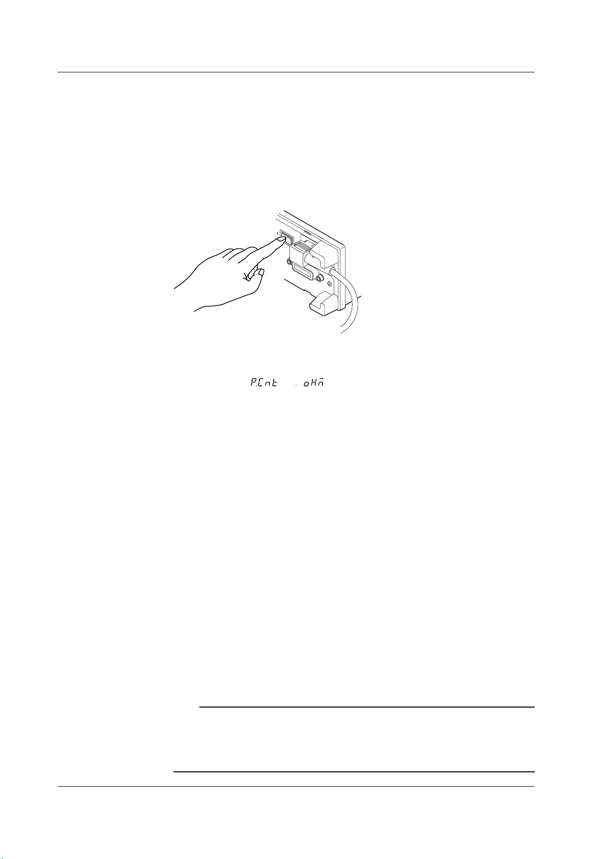
Turning ON/OFF the Power Switch
Turn ON the power by depressing the power switch on the rear panel to the “ON (|)” side
and OFF by depressing it to the “OFF (O) side.”
Power Up Operation
When the power switch is turned ON, the instrument automatically starts a self-test. The
self-test takes approximately 30 seconds. Upon successful completion, the top menu of
the SETUP mode (
measurement mode (the instrument recalls the condition that existed when the power
was turned OFF).
To make a measurement, press the SETUP/MEAS key (SHIFT+R/% key) to switch to
the measurement mode.
If the Instrument Does Not Start Normary When the Power Is Turned On
If the instrument fails to power up as described or the top menu does not appear, turn
OFF the power switch and check the following points.
• Is the power cord securely connected?
• Is the correct voltage coming to the power outlet? See page 3-3.
• If the power switch is turned ON while pressing the SHIFT key, the setup parameters
are initialized to their factory default values. For details regarding initialization, see
section 6.3, “Initializing Setup Parameters” on page 6-7.
If the instrument still fails to power up after checking these points, contact your nearest
YOKOGAWA dealer for repairs.
or ) appears or the instrument enters the
For Making Accurate Measurements
Allow the instrument to warm up for at least 30 minutes after turning ON the power switch.
Shut Down Operation
The setup parameters that exist immediately before the power switch is turned OFF are
stored in memory. The same is true when the power cord gets disconnected from the
outlet. The next time the power switch is turned ON, the instrument powers up using the
previous settings that existed immediately before the power was turned OFF.
Note
A lithium battery is used to retain the setup parameters. The battery has a limited lifetime. When
the lithium battery voltage falls below a certain level, a “901” error code is displayed on the screen
when the power switch is turned ON. When this error code appears, the battery must be
replaced quickly. The user cannot replace the battery. For battery replacement, contact your
nearest YOKOGAWA dealer.
3-4 IM 755601-01E
Page 30
3.4 Wiring
CAUTION
Do not apply any voltage or current across the measurement input
terminals and across the measurement input terminal and the guard
(the outside of the BNC connector). The maximum common-mode
voltage across the case and input terminals is ±42 Vpeak. Not meeting
these conditions can damage the instrument.
Wiring Method
Connect BNC cables to each terminal as shown in the figure below.
L
CUR CURPOTPOT
Resistor under measurement
UNKNOWN
L H H
Do not connect a current/voltage
source to the UNKNOWN terminals.
It will damage the instrument.
ALL TERMINALS 42 V PEAK TO
3
Before Starting Measurements
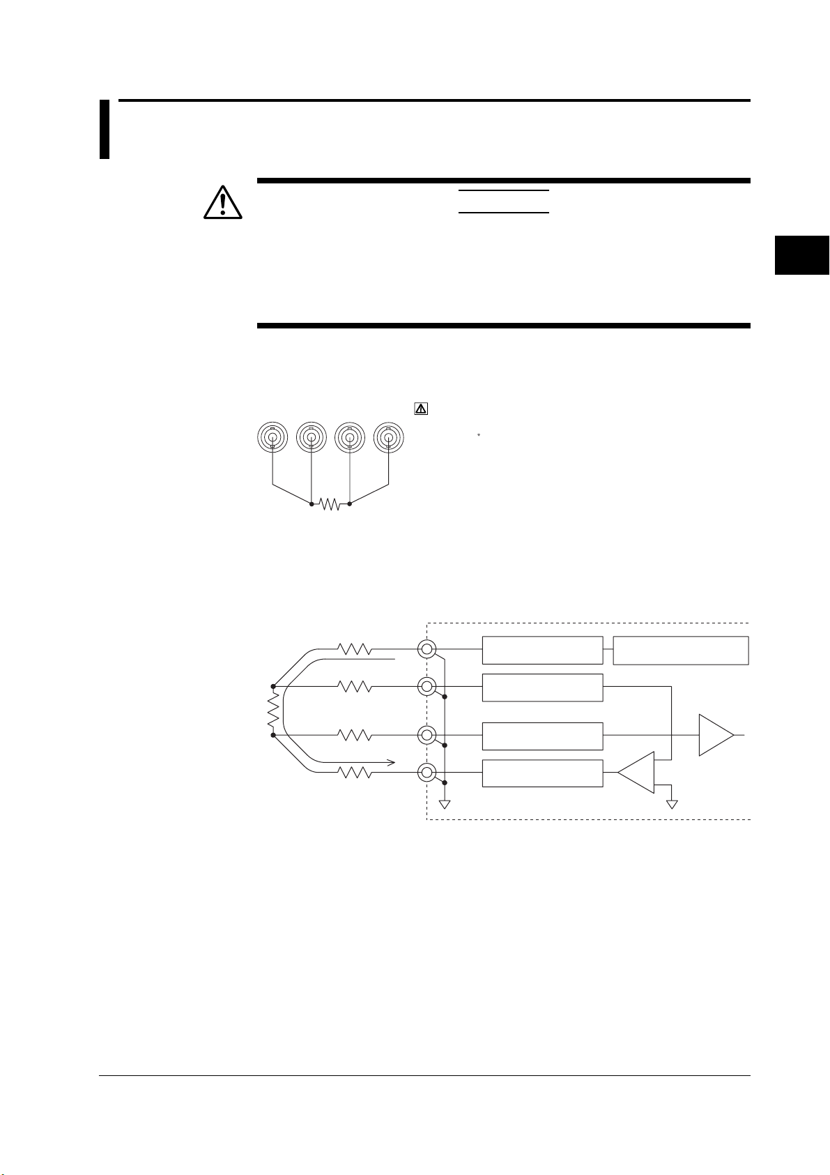
Wiring Precautions
The accuracy specifications can only be met if the following conditions, given in the
wiring example below, are provided.
Wiring Example
r
1
r
2
H
CUR
Circuit used to
detect disconnection
H
POT
Circuit used to
Constant current source
for measurement
detect disconnection
I
R
s
x
r
2
L
POT
Circuit used to
detect disconnection
r
1
L
CUR
Circuit used to
detect disconnection
-
Pre-amp
+
Is: Test current
Rx: Resistor under measurement
r1, r2: Resistance of the lead wires (includes contact resistance)
Is × r1 ≤ 1.5 V: For checking the normal operation of the constant current
source
r2 ≤ 15 Ω (for 1 Ω range): Because the circuit used to detect disconnection feeds a
r2 ≤ 30 Ω (for other ranges) minimal amount of current so that it can detect disconnection
during measurement.
3-5IM 755601-01E
Page 31

3.3 Connecting the Power Cord
Note
• When measuring a resistor that contains capacitive components in parallel, the response
• Since this instrument applies a pulse current to make measurements, when measuring a
• To minimize the influence from noise, make the lead wires as short as possible, and use
• Keep the capacitance of the shielded cable between the measurement input terminal and
• Do not connect the input terminals and the guard. Measurements cannot be made, under this
• For absolute value display (R), drifting occurs near the zero point when the input is shorted,
becomes slow and correct measurements may not be obtained. In this case, turn OFF the
contact check function, and perform the measurement after the response is adequately stable.
resistor that has inductive components in series (wire wound resistor, for example), the
response becomes slow and correct measurements may not be obtained. In addition, if the
inductance exceeds 10 µH, it can cause resonance.
shielded cables. In addition, placing the resistor under measurement inside a shielded case
and connecting the guard (outside of the BNC connector) and the shielded case with shielded
cables are effective means of preventing noise.
guard (outside of the BNC connector) under 300 pF. Resonance can result if this value is
exceeded.
condition.
possibly resulting in the display of a negative value.
For deviation display (%), the display corresponding to -100% (when the input is shorted, for
example) is represented by -99.9%, -99.99%, or -99.999%.
3-6 IM 755601-01E
Page 32

LOCAL key
GP-IB connector
Chapter 4 Setting the Measurement Conditions
4.1 Switching the Limit Mode
Keys
Indicator is off during SETUP mode
HIGH
SPEED
MΩ
kΩ
STORE
DATA
%
Ω
Procedure
NORMAL
MEAS&
LOCK
SAMPLE
EXTERNAL
MANUAL
FAST
REFERENCE
The items that are specified or selected are confirmed when the ENTER (Ω,%) key is
pressed. To exit from a menu in the middle of the operation, press the EXIT (R/%) key.
RECALL
DATA
HI
IN
LO
CHECK REMOTE
HI LIMIT
LO LIMIT
SETUP/MEAS
SHIFT
7
%
MEAS
TIME
Ω
1
0
STORE
DATA
REF LIMIT
R/%
EXIT
LOCAL
TRIG
TRIG
MODE
M
CHECK
k
MISCI/F
,%
Ω
ENTER
Ω
Ω
89
LIMIT
MODE
546
23
.
RECALL
DATA
4
Setting the Measurement Conditions
Explanation
Switching to the SETUP mode
1. Press the
SHIFT
SETUP/MEAS
R/%
key to switch to the SETUP mode. If the “MEAS & LOCK”
indicator is off, this operation is not necessary.
Switching the limit mode
2. 4.
8
3.
LIMIT
SHIFT
MODE
REF LIMIT
[Main display]
(Deviation mode)
(Absolute mode)
Ω
,%
ENTER
There are two limit modes.
You can select whether to use a deviation (%) or an absolute value (R) for the
comparator function.
• Deviation (%) mode: The measured value is handled as a deviation from the
specified reference value. The comparator function is also
carried out in terms of the deviation.
• Absolute (R) mode: The measured value is handled as an absolute value. The
comparator function is also carried out in terms of the absolute
value.
Precautions to be taken when switching the limit mode
The following parameters are initialized when the limit mode is switched.
HI level, LO level, and REF (reference, when the limit mode is set to %)
4-1IM 755601-01E
Page 33

4.2 Changing the Range (Reference)
When the limit mode is set to deviation (%)
Keys
HIGH
STORE
RECALL
DATA
HI
IN
LO
CHECK REMOTE
HI LIMIT
LO LIMIT
Procedure
NORMAL
FAST
SPEED
MEAS&
LOCK
SAMPLE
EXTERNAL
MANUAL
REFERENCE
DATA
%
MΩ
kΩ
Ω
The items that are specified or selected are confirmed when the MΩ, kΩ, or ENTER
(Ω,%) key is pressed. When confirmed, the new reference is displayed.
To exit from a menu in the middle of the operation, press the EXIT (R/%) key. The
display returns to the top menu of the SETUP mode.
SETUP/MEAS
SHIFT
7
%
MEAS
TIME
Ω
1
0
STORE
DATA
REF LIMIT
R/%
EXIT
LOCAL
TRIG
TRIG
MODE
M
CHECK
k
Ω
MISCI/F
,%
Ω
ENTER
Ω
89
LIMIT
MODE
546
23
.
RECALL
DATA
Switching to the SETUP mode
1. Press the
SHIFT
SETUP/MEAS
R/%
key to switch to the SETUP mode. If the “MEAS & LOCK”
indicator is off (if PCnt or oHm is displayed on the main display), this operation is
not necessary.
Changing the reference value
2. 4.
REF
3. Numerical keys
[REFERENCE
display]
M
Ω
(Press when the unit is MΩ.)
CHECK
k
Ω
(Press when the unit is kΩ.)
MISC
Ω
,%
(Press when the unit is Ω.)
ENTER
If the value entered using the numerical keys is not correct, an error (810) is displayed
for approximately one second, and the display returns to step 3.
Explanation
When the reference value is entered, the range is automatically determined.
The range and the display range are set according to the specified reference as follows.
For the procedure to set the percent limit, see section 4.3, “Using the Comparator
Function.”
When the percent limit is set to 9.99%
Reference Range Display Range
0.0001 to 1.0009 Ω 1 Ω “-99.999%
1.001 to 10.009 Ω 10 Ω to
10.01 to 100.009 Ω 100 Ω 19.999%”
0.1001 k to 1.0009 kΩ 1 kΩ (for 755611)
1.001 k to 10.009 kΩ 10 kΩ
10.01 k to 100.09 kΩ 100 kΩ
0.1001 M to 1.0009 MΩ 1 MΩ
1.001 M to 10.009 MΩ 10 MΩ
10.01 M to 120.00 MΩ 100 MΩ
*1 “-99.99% to 19.99%” for 755601
4-2 IM 755601-01E
*1
Page 34

When the percent limit is set to 99.9%
Reference Range Display Range
0.001 to 1.009 Ω 10 Ω “-99.99%
1.01 to 10.09 Ω 100 Ω to
10.1 to 100.09 Ω 1 kΩ 199.99%”
0.101 k to 1.009 kΩ 10 kΩ (for 755611)
1.01 k to 10.09 kΩ 100 kΩ
10.1 k to 100.9 kΩ 1 MΩ
0.101 M to 1.009 MΩ 10 MΩ
1.01 M to 10.09 MΩ 100 MΩ
10.1 M to 120.0 MΩ 100 MΩ
*2 “-99.9% to 199.9%” for 755601
*2
4.2 Changing the Range (Reference)
When the limit mode is set to absolute (R)
When the limit mode is set to absolute (R), the range is fixed to 1 Ω. You cannot change
this value.
Maximum displayed value: 1.20000 (755611)
Measurement resolution: 10 µ Ω (755611)
4
Setting the Measurement Conditions
1.2000 (755601)
100 µ Ω (755601)
4-3IM 755601-01E
Page 35

4.3 Using the Comparator Function
When the limit mode is set to deviation (%)
Keys
Indicates the comparator result
Set/Display HI limit value
HIGH
STORE
RECALL
DATA
HI
IN
LO
CHECK REMOTE
HI LIMIT
LO LIMIT
Procedure
NORMAL
FAST
SPEED
MEAS&
LOCK
SAMPLE
EXTERNAL
MANUAL
REFERENCE
DATA
%
MΩ
kΩ
Ω
Set/Display LO limit value
The items that are specified or selected are confirmed when the ENTER (Ω,%) key is
pressed. When confirmed, the new limit is displayed.
To exit from a menu in the middle of the operation, press the EXIT (R/%) key. The
display returns to the top menu of the SETUP mode.
SETUP/MEAS
SHIFT
7
%
MEAS
TIME
Ω
1
0
STORE
DATA
REF LIMIT
R/%
EXIT
LOCAL
TRIG
TRIG
MODE
M
CHECK
k
Ω
MISCI/F
,%
Ω
ENTER
Ω
89
LIMIT
MODE
546
23
.
RECALL
DATA
Switching to the SETUP mode
1. Press the
SHIFT
SETUP/MEAS
R/%
key to switch to the SETUP mode. If the “MEAS & LOCK”
indicator is off, this operation is not necessary.
Changing the limit value (HI and LO values)
2. 4.
LIMIT
3. Numerical keys
[HI LIMIT display]
Ω
,%
ENTER
5. Numerical keys
[LO LIMIT display]
6.
Ω
,%
ENTER
If the value entered using the numerical keys is not correct, an error (810) is displayed
for approximately one second, and the display returns to step 3.
Selecting the percent limit
2.
k
Ω
3.
MISC
SHIFT
REF
[Main display]
LIMIT
(Plimit)
4.
Ω
,%
ENTER
5.
REF LIMIT
[Main display]
*
*
6.
Ω
,%
ENTER
* For 755611. For 755601, select either “9.99” or “99.9.”
4-4 IM 755601-01E
Page 36

Explanation
4.3 Using the Comparator Function
Setting range of limit values (HI and LO values)
The limit value is set in terms of the deviation (%) from the reference value that was set
in section 4.3, “Changing the Range (Reference).”
Limit Value Setting Range
When the percent limit is 9.99% When the percent limit is 99.9%
Applies to both LO, HI -9.999% to 9.999% (755611) -99.99% to 99.99% (755611)
-9.99% to 9.99% (755601) -99.9% to 99.9% (755601)
However, LO ≤ HI
Note
If the values are set so that HI is less than LI, an error (815) occurs.
Selecting the percent limit
Percent limit refers to the display resolution when the measured values are handled in
terms of deviation (%).
Select the percent limit from the following two choices.
9.99%
99.9%
Note that depending on the selected percent limit, the range of limit values (LO and HI
values) varies as indicated in the above section “Setting range of limit values (HI and LO
values).”
Note
• Changing the percent limit initializes the limit values (HI and LO) to 0%.
•If the percent limit is changed from 9.99% to 99.9%, the reference value is rounded to the least
significant digit. However, if the limit mode is 9.99% and the reference value is between 0.0001
Ω to 0.0004 Ω, changing the limit mode to 99.9% changes the reference value to 0.001 Ω.
Comparator function
The measured value is compared to the specified limit values (HI and LO) and the result
is indicated by turning ON the appropriate indicator.
The comparator result is also output from the handler interface.
The following comparison is made.
When the measured value > HI : “HI” (
When the measured value < LO : “LO” (
When the measured value is between LO and HI : “IN” (
“–OL–” (overrange), : “HI” (
“–nC–” (contact check error),
“–CF–” (Abnormality detected in the test current)
indicator) turns ON (red)
indicator) turns ON (red)
indicator) turns ON (green)
indicator) turns ON (red)
4
Setting the Measurement Conditions
Note
The comparator function is carried out using fractions with greater accuracy than those displayed.
4-5IM 755601-01E
Page 37

4.3 Using the Comparator Function
When the limit mode is set to absolute (R)
Keys
NORMAL
MEAS&
LOCK
SAMPLE
EXTERNAL
MANUAL
FAST
REFERENCE
Procedure
The items that are specified or selected are confirmed when the ENTER (Ω,%) key is
pressed. When confirmed, the new reference is displayed.
To exit from a menu in the middle of the operation, press the EXIT (R/%) key. The
display returns to the top menu of the SETUP mode.
HIGH
SPEED
Indicates the comparator result
STORE
RECALL
DATA
HI
IN
LO
CHECK REMOTE
LO LIMIT
DATA
%
MΩ
kΩ
Ω
Set/Display LO limit value
Set/Display HI limit value
SETUP/MEAS
HI LIMIT
SHIFT
7
%
MEAS
TIME
Ω
1
0
STORE
DATA
REF LIMIT
R/%
EXIT
LOCAL
TRIG
TRIG
MODE
M
CHECK
k
Ω
MISCI/F
,%
Ω
ENTER
Ω
89
LIMIT
MODE
546
23
.
RECALL
DATA
Explanation
Switching to the SETUP mode
1. Press the
SHIFT
SETUP/MEAS
R/%
key to switch to the SETUP mode. If the “MEAS & LOCK”
indicator is off, this operation is not necessary.
Changing the limit values
2.
LIMIT
3. Numerical keys 5. Numerical keys 6.
[HI LIMIT display] [LO LIMIT display]
4.
Ω
,%
ENTER
Ω
,%
ENTER
If the value entered using the numerical keys is not correct, an error (810) is displayed
for approximately one second, and the display returns to step 3.
Setting range of limit values
The setting range applies to both HI and LO.
Model Setting Range Resolution
755601 0.000 Ω to 1.200 Ω 1 mΩ
755611 0.0000 Ω to 1.2000 Ω 100 µ Ω
However, LO ≤ HI
Note
If the values are set so that HI becomes less than LI, an error (815) occurs.
Comparator function
Same as the description given in “When the limit mode is set to deviation (%).” See
page 4-5.
4-6 IM 755601-01E
Page 38

4.4 Using the Contact Check Function
2. 4.
3.
6.5. Numerical keys
(Contact check level)
CHECK
ENTER
SHIFT
REF
LIMIT
M
Ω
Ω
,%
ENTER
Ω
,%
ENTER
Ω
,%
[Main display]
Keys
Indicator is ON while contact check
is in progress
HIGH
STORE
RECALL
DATA
HI
IN
LO
CHECK REMOTE
HI LIMIT
LO LIMIT
%
Ω
Procedure
NORMAL
FAST
SPEED
MEAS&
LOCK
SAMPLE
EXTERNAL
MANUAL
REFERENCE
DATA
%
MΩ
kΩ
Ω
The items that are specified or selected are confirmed when the ENTER (Ω,%) key is
pressed. When confirmed, the display returns to the top menu of the SETUP mode.
To exit from a menu in the middle of the operation, press the EXIT (R/%) key. The
display returns to the top menu of the SETUP mode.
SETUP/MEAS
R/%
SHIFT
EXIT
89
7
MEAS
LIMIT
TIME
MODE
546
1
23
.
0
STORE
RECALL
DATA
DATA
REF LIMIT
TRIG
TRIG
MODE
M
CHECK
k
MISCI/F
Ω
ENTER
LOCAL
Ω
Ω
,%
4
Setting the Measurement Conditions
Explanation
Switching to the SETUP mode
1. Press the
SHIFT
SETUP/MEAS
R/%
key to switch to the SETUP mode. If the “MEAS & LOCK”
indicator is off, this operation is not necessary.
Using the contact check
If the value entered using the numerical keys is not correct, an error (810) is displayed
for approximately one second, and the display returns to step 5.
Contact check function
If the result of the contact check is larger than the specified check level, an error is
generated. The time duration of the check is 2 ms, and the check current is 50 mA.
The timing to perform the contact check can be selected from the following choices.
OFF: Contact check is not performed.
bEF: Contact check is performed before the measurement. If an error is detected, “–nC–” is
displayed and the “HI” indicator ( ) turns ON. “HI” “NO CONTACT” signal is output
from the handler interface.
AFt: Contact check is performed after the measurement. If an error is detected, “–nC–”
is displayed and the “HI” indicator (
) turns ON. “HI” “NO CONTACT” signal is
output from the handler interface.
Setting range of the check level
1 to 30 Ω (1 Ω resolution).
4-7IM 755601-01E
Page 39

4.5 Setting the Measurement Time
Keys
The appropriate indicator turns ON
HIGH
STORE
RECALL
DATA
HI
IN
LO
CHECK REMOTE
HI LIMIT
LO LIMIT
Procedure
NORMAL
FAST
SPEED
MEAS&
LOCK
SAMPLE
EXTERNAL
MANUAL
REFERENCE
DATA
%
MΩ
kΩ
Ω
The items that are specified or selected are confirmed when the ENTER (Ω,%) key is
pressed. When confirmed, the display returns to the top menu of the SETUP mode.
To exit from a menu in the middle of the operation, press the EXIT (R/%) key. The
display returns to the top menu of the SETUP mode.
SETUP/MEAS
SHIFT
7
%
MEAS
TIME
Ω
1
0
STORE
DATA
REF LIMIT
R/%
EXIT
LOCAL
TRIG
TRIG
MODE
M
CHECK
k
Ω
MISCI/F
,%
Ω
ENTER
Ω
89
LIMIT
MODE
546
23
.
RECALL
DATA
Explanation
Switching to the SETUP mode
1. Press the
SHIFT
SETUP/MEAS
R/%
key to switch to the SETUP mode. If the “MEAS & LOCK”
indicator is off, this operation is not necessary.
Selecting the measurement time
LIMIT
[Main display]
Ω
,%
ENTER
2.
7
TIME
3.
REF
SHIFT
MEAS
Measurement time
Select from the following choices.
Type Measurement Time* (when the measurement range is 1 Ω to 1 MΩ)
nor (NORMAL) 19.9 ms (for 60 Hz)
FASt (FAST) 5.7 ms
H-SP (HIGH SPEED) 2.8 ms
* Measurement time: When the trigger mode is set to EXTERNAL, the time from the trigger
23.2 ms (for 50 Hz)
input to the falling edge of the EOM signal of the handler interface is
called the measurement time.
When the trigger mode is set to Manual or Internal, the EOM signal is not
output.
When the contact check function is ON (before the measurement), add 2 ms.
When the contact check function is ON (after the measurement), add 1 ms.
When a trigger delay is specified, add the delay time.
When the measurement range is 10 MΩ, add 4 ms.
When the measurement range is 100 MΩ, add 50 ms.
4-8 IM 755601-01E
Page 40

4.6 Using the Trigger Function
Keys
Procedure
SHIFT
7
MEAS
TIME
1
0
STORE
DATA
SETUP/MEAS
REF LIMIT
R/%
EXIT
LOCAL
TRIG
TRIG
MODE
M
CHECK
k
MISCI/F
,%
Ω
ENTER
89
LIMIT
MODE
546
23
.
RECALL
DATA
Ω
Ω
HIGH
MEAS&
LOCK
SAMPLE
EXTERNAL
MANUAL
NORMAL
FAST
REFERENCE
SPEED
MΩ
kΩ
STORE
DATA
Turns ON during manual trigger
Turns ON during external trigger
RECALL
CHECK REMOTE
DATA
HI
%
IN
LO
Ω
HI LIMIT
%
Ω
LO LIMIT
The items that are specified or selected are confirmed when the ENTER (Ω,%) key is
pressed. When confirmed, the display returns to the top menu of the SETUP mode.
To exit from a menu in the middle of the operation, press the EXIT (R/%) key. The
display returns to the top menu of the SETUP mode.
Switching to the SETUP mode
1. Press the
SHIFT
SETUP/MEAS
R/%
key to switch to the SETUP mode. If the “MEAS & LOCK”
indicator is off, this operation is not necessary.
Selecting the trigger mode
LIMIT
[Main display]
(EXTERNAL)
(MANUAL)
Ω
,%
ENTER
2. 4.
SHIFT
TRIG
MODE
TRIG
3.
REF
4
Setting the Measurement Conditions
(INTERNAL)
Setting the trigger delay
2.
k
Ω
3.
MISC
SHIFT
REF
[Main display]
LIMIT
4.
ENTER
5. Numerical keys
Ω
,%
[Main display]
6.
Ω
,%
ENTER
If the value entered using the numerical keys is not correct, an error (810) is displayed
for approximately one second, and the display returns to step 5.
4-9IM 755601-01E
Page 41

TRIG
MODE
TRIG
4.6 Using the Trigger Function
Selecting the edge
2.
SHIFT
k
MISC
[Main display]
Ω
3.
REF
LIMIT
Explanation
4.
Ω
,%
ENTER
Manual trigger (only when the trigger mode is set to MANUAL)
1. Press the
SHIFT
SETUP/MEAS
R/%
key to switch to the measurement mode.
2. Trigger is activated every time the
5.
REF LIMIT
key is pressed.
[Main display]
CAUTION
Applying a voltage outside the 0 to 5 V range to the external trigger input
terminal (TRIGGER IN) can damage the instrument.
External trigger input terminal (TRIGGER IN)
Specifications
Connector type : BNC
Input level : CMOS
Minimum pulse width : 100 µ s
6.
Ω
,%
ENTER
Input circuit (non-isolated)
+5 V
10 kΩ
+5 V
100 Ω
CMOS
4-10 IM 755601-01E
Page 42

4.6 Using the Trigger Function
Selecting the trigger mode
Select from the following list of choices.
EXTERNAL: Trigger is activated using the input signal at the external trigger input
terminal or the number 8 pin of the handler interface, and the
measurement is made.
MANUAL: Measurement is made when the TRIG key is pressed or when a trigger is
activated using a communication command.
INTERNAL: Measurement is made at intervals according to the specified
measurement time.
Setting the trigger delay
The trigger delay setting takes effect when the trigger mode is set to EXTERNAL or
MANUAL.
The range and resolution are as follows:
Range: 0 to 1000 ms
Resolution: 0.1 ms
Selecting the trigger edge
The selected edge takes effect only when the trigger mode is set to EXTERNAL.
Rise (rising edge): Trigger occurs at the rising edge of the signal.
Fall (falling edge): Trigger occurs at the falling edge of the signal.
Measurement interval for INTERNAL (internal trigger)
When the trigger mode is set to INTERNAL, the measurement interval is set to the
following values depending on the specified measurement time.
Measurement Time Measurement Interval
NORMAL 50 ms
FAST 20 ms
HIGH SPEED 10 ms
However, the measurement interval is adjusted by adding the appropriate values for the following
cases: 5/10/15 ms when the pulse width of the EOM signal of the handler interface is set to 5/10/
15 ms, respectively, 5 ms when the contact check function is ON, 5 ms when the range is 10 MΩ,
and 50 ms when the range is 100 MΩ.
4
Setting the Measurement Conditions
4-11IM 755601-01E
Page 43

LOCAL key
NORMAL
MEAS&
LOCK
SAMPLE
EXTERNAL
REFERENCE
MANUAL
FAS T
HI
HI LIMIT
EXIT
SETUP/MEAS
CHECK
MISCI/F
MEAS
TIME
STORE
DATA
RECALL
DATA
LOCAL
ENTER
LIMIT
MODE
TRIG
MODE
SHIFT
R/%
REF LIMIT
TRIG
7
1
0
.
23
546
89
LO LIMIT
IN
LO
MΩ
M
Ω
k
Ω
Ω
,%
kΩ
Ω
Ω
%
%
HIGH
SPEED
STORE
DATA
RECALL
DATA
CHECK REMOTE
Displays the measured value
Indicator is ON during the measurement mode
Blinks every data sample
GP-IB connector
Chapter 5 Making Measurements
5.1 Setting the Measurement Mode
Keys
Procedure
Explanation
SETUP/MEAS
Press the
SHIFT
R/%
key to switch to the measurement mode. If the “MEAS & LOCK”
indicator is off, this operation is not necessary.
In the measurement mode, measurements are made according to the various specified
settings such as the trigger mode, measurement time, and range. The measured value
is displayed using seven-segment digital characters.
You can not change the settings in the measurement mode.
The following keys can be used in the measurement mode.
• SETUP/MEAS (SHIFT+R/%) key: Used to switch between the measurement and
SETUP modes.
• TRIG key: Pressing this key when the trigger mode is set to
MANUAL activates a trigger.
• R/% key: Used to switch the display when the limit mode is
set to deviation (%).
• STORE DATA (SHIFT+0) key: Pressing this key while making measurements
causes the “STORE DATA” indicator to turn ON
and the instrument to enter a state in which data
can be stored. Pressing this key while the
instrument is storing data terminates the store
operation.
• RECALL DATA (SHIFT+ .) key: Pressing this key while the instrument is recalling
data (“RECALL DATA” indicator is ON)
terminates the recall operation.
5
Making Measurements
The error displays for measured values are as follows:
• When the value is over the range:
• When a contact check error occurs:
• When abnormalities are detected in the test current:
For details regarding the error displays, see page 2-4.
5-1IM 755601-01E
Page 44

5.1 Setting the Measurement Mode
Precautions to be taken during measurement
Precautions on the “HOLD” signal of the handler interface
When the HOLD signal of the handler interface is set to “L,” the instrument switches to
the measurement mode regardless of the mode it is currently in (the trigger mode is set
to EXTERNAL), and makes measurements. Since the SETUP/MEAS key is locked, you
will not be able to switch modes using the key. If you wish to do so, first, set the HOLD
signal to “H,” then change the mode using the key or a communication command.
Simply changing the HOLD signal from “L” to “H” does not change the mode. The
measurement continues in this case.
Note
Use the SETUP mode to change the reference value and limit values.
Precautions to be taken when using the trigger input signal
When activating the trigger with the input signal applied to the external trigger input
terminal on the rear panel or the number 8 pin of the handler interface (EXT TRIG), the
unused terminal or pin must be set to open or HI level. Otherwise, the trigger will not
function.
5-2 IM 755601-01E
Page 45

5.2 Switching between Deviation (%) and Absolute (R) Displays
Keys
Procedure
Explanation
HIGH
STORE
RECALL
NORMAL
FAST
SPEED
MEAS&
LOCK
SAMPLE
EXTERNAL
MANUAL
REFERENCE
1. Press the
LOCK” indicator is off, this operation is not necessary.
2. Press the
SHIFT
SETUP/MEAS
R/%
DATA
%
MΩ
kΩ
Ω
SETUP/MEAS
R/%
key to switch to the measurment mode. If the “MEAS &
key to set the displayed unit of the measured value to % (deviation
DATA
HI
IN
LO
CHECK REMOTE
HI LIMIT
LO LIMIT
%
Ω
SETUP/MEAS
R/%
SHIFT
EXIT
89
7
MEAS
LIMIT
TIME
MODE
546
23
1
.
0
STORE
RECALL
DATA
DATA
REF LIMIT
TRIG
TRIG
MODE
M
CHECK
k
MISCI/F
Ω
ENTER
LOCAL
Ω
Ω
,%
display) or Ω (absolute display).
Switching between the deviation (%) and absolute (R) displays
You can switch the display during measurements (in the measurement mode).
The display unit can be switched only when the limit mode is set to deviation (%).
Note
The measured value displayed in the deviation display may differ from that displayed in the
absolute display by one digit due to the different methods used to handle the fractional values.
5
Making Measurements
5-3IM 755601-01E
Page 46

LOCAL key
GP-IB connector
Chapter 6 Other Functions
6.1 Store/Recall Measured Data
Keys
Indicator is ON while storing data
Indicator is ON while recalling data
HIGH
STORE
RECALL
DATA
DATA
HI
%
MΩ
kΩ
IN
LO
Ω
Procedure
NORMAL
FAST
MEAS&
LOCK
SAMPLE
EXTERNAL
MANUAL
REFERENCE
SPEED
The items that are specified or selected are confirmed when the ENTER (Ω,%) key is
pressed. When confirmed, the display returns to the top menu of the SETUP mode.
To exit from a menu in the middle of the operation, press the EXIT (R/%) key. The
display returns to the top menu of the SETUP mode.
CHECK REMOTE
HI LIMIT
LO LIMIT
SETUP/MEAS
SHIFT
7
%
MEAS
TIME
Ω
1
0
STORE
DATA
REF LIMIT
R/%
EXIT
LOCAL
TRIG
TRIG
MODE
M
CHECK
k
MISCI/F
,%
Ω
ENTER
Ω
Ω
89
LIMIT
MODE
546
23
.
RECALL
DATA
6
Other Functions
Setting the number of data sets to be stored
1. Press the
SHIFT
SETUP/MEAS
R/%
key to switch to the SETUP mode. If the “MEAS & LOCK”
indicator is off, this operation is not necessary.
2.
0
STORE
SHIFT
DATA
Storing data
1. Pressing the
[Main display, number of
data sets to store]
0
key in the measurement mode (“MEAS & LOCK” is ON)
STORE
SHIFT
DATA
4.3. Numerical keys
Ω
,%
ENTER
causes the “STORE DATA” indicator to turn ON and the instrument to store one
data set for every trigger.
After storing the specified number of data sets, the store operation terminates and
the “STORE DATA” indicator turns OFF.
Aborting the store operation
0
2. Pressing the
SHIFT
key while the store operation is in progress aborts the
STORE
DATA
operation and the “STORE DATA” indicator turns OFF. Then, the display returns to
the top menu of the SETUP mode.
Recalling data
1. In the SETUP mode, press the
indicator.
2. Press the
SHIFT
SETUP/MEAS
R/%
key to switch to the measurement mode (“MEAS & LOCK” is
SHIFT
.
key to turn ON the “RECALL DATA”
RECALL
DATA
ON). A data set is recalled every time a trigger occurs.
After recalling all stored data, the operation terminates and the “RECALL DATA”
indicator turns OFF.
Aborting the recall operation
3. Pressing the
SHIFT
.
key while the recall operation is in progress aborts the
RECALL
DATA
operation and the “RECALL DATA” indicator turns OFF.
6-1IM 755601-01E
Page 47

6.1 Store/Recall Measured Data
Note
• Pressing the STORE DATA (SHIFT+0) key in the measurement mode while the store
• Pressing the RECALL DATA (SHIFT+ .) key while the recall operation is in progress
Explanation
Storing measured data
Up to 2000 measured data sets can be stored in the internal memory. The data are
cleared when the power is turned OFF or the settings are initialized. By using the
optional Centronics interface, statistics on the stored data can be computed and printed
to an external printer. For the procedures related to printing, see section 6.2.
Timing used to store or recall data
When the “STORE DATA” or “RECALL DATA” indicator is ON in the measurement
mode, measured data are stored or recalled every time a trigger occurs.
The timing used to store or recall data varies depending on the trigger mode as follows:
EXTERNAL: Data are stored or recalled when a trigger is activated using the input
MANUAL: Data are stored or recalled when the TRIG key is pressed or when a
INTERNAL: Data are stored or recalled at measurement intervals according to the
operation is in progress (“STORE DATA” indicator is ON) aborts the operation and continues
the measurement.
(“RECALL DATA” indicator is ON) aborts the operation and continues the measurement.
signal at the external trigger input terminal or the number 8 pin of the
handler interface.
trigger is activated using a communication command.
specified measurement time. For details regarding the measurement
interval, see page 4-11.
Precautions to be taken when storing data
• The STORE DATA (SHIFT+0) key can be used even in the measurement mode
(when the measurement is in progress).
• Executing a store operation, clears the previously stored data.
• Data cannot be stored when the “RECALL DATA” indicator is ON. An error (831) is
displayed in this case.
• When the store operation is aborted, data stored up to that point can be recalled.
Precautions to be taken when recalling data
• Data are recalled in order from the first data in the memory. After recalling all of the
data, the instrument continues the measurement.
• Data cannot be recalled when the “STORE DATA” indicator is ON. An error (832) is
displayed in this case.
• If there are no stored data in the memory, an error (830) is displayed for
approximately one second, and the display returns to the top menu of the SETUP
mode.
6-2 IM 755601-01E
Page 48

6.2 Printing Data
Keys
Procedure
SETUP/MEAS
R/%
SHIFT
EXIT
89
7
MEAS
LIMIT
TIME
MODE
546
23
1
.
0
STORE
RECALL
DATA
DATA
REF LIMIT
LOCAL
MEAS&
LOCK
SAMPLE
EXTERNAL
MANUAL
NORMAL
FAST
REFERENCE
HIGH
SPEED
MΩ
kΩ
STORE
DATA
%
Ω
RECALL
DATA
HI
IN
LO
CHECK REMOTE
HI LIMIT
LO LIMIT
%
Ω
The items that are specified or selected are confirmed when the ENTER (Ω,%) key is
pressed. When confirmed, the display returns to the top menu of the SETUP mode.
To exit from a menu in the middle of the operation, press the EXIT (R/%) key. The
display returns to the top menu of the SETUP mode.
SETUP/MEAS
1. Press the
SHIFT
R/%
key to switch to the SETUP mode. If the “MEAS & LOCK”
indicator is off, this operation is not necessary.
2. Store the measured data according to the procedures given in section 6.1, “Store/
Recall Measured Data.”
Selecting whether or not to output the measured data
3.
k
Ω
SHIFT
MISC
4.
REF
LIMIT
[Main display]
5.
Ω
,%
ENTER
6.
REF LIMIT
[Main display]
TRIG
TRIG
MODE
M
CHECK
k
MISCI/F
,%
Ω
ENTER
Ω
Ω
6
Other Functions
7.
Ω
,%
ENTER
6-3IM 755601-01E
Page 49

6.2 Printing Data
3.
k
Ω
MISC
SHIFT
Explanation
4.
REF
Start/Stop printing
[Main display] [Main display]
LIMIT
5.
Ω
,%
ENTER
6.
REF LIMIT
7.
Ω
,%
ENTER
(Indicates that data
are being transferred
to the printer)
Ω
,%
(Abort printing)
ENTER
By using the optional Centronics interface, statistics on the stored data can be computed
and printed to an external printer.
CAUTION
Use a Centronics printer cable to connect an external printer to the
instrument. A bad connection can damage the instrument and/or other
devices that are connected to it.
Pin arrangement of the Centronics interface connector
18
36
For details, contact your nearest
YOKOGAWA dealer.
1
19
Pin No.
Pin No.
1
2
9
10
11
12
13
14
15
16
17
18
Signal
STROBE (Strobe)
DATA0 (Print data bit 0)
DATA7 (Print data bit 7)
ACK (Acknowledge)
BUSY (Busy)
PE (Paper end)
SLCT (Select)
NC (No connection)
NC (No connection)
GND (Ground)
GND (Ground)
NC (No connection)
Pin No.
19
30
31
32
33
34
35
36
Signal
GND (Ground)
GND (Ground)
INIT (Initialize printer)
ERROR (Error)
GND (Ground)
NC (No connection)
NC (No connection)
NC (No connection)
6-4 IM 755601-01E
Page 50

6.2 Printing Data
Output items
Output Items Description, Limitations
Number of stored data points
Reference value Not output when the limit mode is set to absolute (R).
Limit values (LO, HI)
Comparator result Frequencies of HI, IN, and LO results
Contact check error Frequencies of –nC– and –CF– results
Statistics
Number of valid samples
Number of invalid samples Frequencies of oL, nC, and CF results
Max. and min. values of data
P-P value of data Maximum value – minimum value
Data average
Standard deviation of data (σ)
3σ of data
Stored measurement data Select whether or not to output data
Selecting whether or not to output measured data
You can select whether or not to output measured data and the paper size used for
printing
oFF.rP: Print to a paper size (roll paper) on which 40 characters can be printed
horizontally and do not output the stored measurement data.
on.rP: Print to a paper size (roll paper) on which 40 characters can be printed
horizontally and output the stored measurement data.
oFF.A4: Print to an A4 size paper, and do not output the stored measurement data.
on.A4: Print to an A4 size paper, and output the stored measurement data.
6
Other Functions
Start/Stop printing
Selecting “on” in the printing start/stop menu starts the print operation. “Print” is
displayed while data transfer is in progress.
Selecting “on” in the printing start/stop menu stops the print operation.
Precautions to be taken while printing
• After printing all items, printing is automatically turned OFF.
• To stop printing, set the print setting to OFF. The printing will be aborted.
• An error (830) is displayed when there are no stored data.
• Since printing is done in the SETUP mode, measurements cannot be made while
printing.
• The measurement and SETUP modes cannot be switched while printing.
• If the HOLD signal of the handler interface changes to “L” (active) while printing, the
instrument aborts the printing operation and starts the measurement.
Note
Statistics are determined on the values that are displayed.
6-5IM 755601-01E
Page 51

6.2 Printing Data
Print example
6-6 IM 755601-01E
Page 52

6.3 Initializing the Setup Information
Keys
Procedure
SETUP/MEAS
R/%
SHIFT
EXIT
89
7
MEAS
LIMIT
TIME
MODE
546
23
1
.
0
STORE
RECALL
DATA
DATA
REF LIMIT
TRIG
TRIG
MODE
M
CHECK
k
MISCI/F
Ω
ENTER
LOCAL
Ω
Ω
,%
MEAS&
LOCK
SAMPLE
EXTERNAL
MANUAL
NORMAL
FAST
REFERENCE
HIGH
SPEED
MΩ
kΩ
STORE
DATA
%
Ω
RECALL
DATA
HI
IN
LO
CHECK REMOTE
HI LIMIT
LO LIMIT
%
Ω
Initializing the settings
The items that are specified or selected are confirmed when the ENTER (Ω,%) key is
pressed. When confirmed, the display returns to the top menu of the SETUP mode.
To exit from a menu in the middle of the operation, press the EXIT (R/%) key. The
display returns to the top menu of the SETUP mode.
SETUP/MEAS
1. Press the
SHIFT
R/%
key to switch to the SETUP mode. If the “MEAS & LOCK”
indicator is off, this operation is not necessary.
2.
k
Ω
SHIFT
MISC
3.
REF
[Main display]
LIMIT
6
Other Functions
Explanation
4.
Ω
,%
ENTER
Resetting the instrument to the factory default settings
Turn ON the power switch on the rear panel while pressing the
key. Keep pressing
SHIFT
the SHIFT key until the top menu appears on the screen.
The setup information can be set to “initial settings” or “factory default settings.” This act
is called initializing.
Initializing the setup information does not initialize settings related to communications.
For details related to the initializing of the setup information, see section 1.4, “A List of
Initial Values.”
6-7IM 755601-01E
Page 53

LOCAL key
GP-IB connector
Chapter 7 Using the Handler Interface
7.1 Handler Interface Functions and Specifications
Handler Interface Specifications
The types of interface signals are as follows:
• Comparator result output signal (HI, IN, LO)
• Handshaking signal (EXT TRIG, INDEX, EOM)
• Key lock control signal (HOLD)
• Power supply (+12V, COM)
Specifications
Pin No. Signal Active Cond. I/O Function/Operation
1HIL Output L when the comparator result is HI
2INL Output L when the comparator result is IN
3LOL Output L when the comparator result is LO
4 NO CONTACT L Output L when a contact check error occurs or when
an abnormality is detected in the test current
7 +12 V — Output Power supply
8 EXT TRIG Specified edge Input External trigger signal*1
9 EOM L Output L when the measurement is complete and
the comparator result is output*2
10 HOLD L Input Key lock*3
11 INDEX L Output H during trigger input, L when data collection
is complete*4
14 COM — — Common
*1 The minimum pulse width is 100 µs.
*2 The pulse width can be set to 0.1, 5, 10, or 15 ms. The initial setting is 10 ms.
*3 When the signal is in the active state (L), the instrument switches to the measurement mode
regardless of the mode it is currently in (the trigger mode is set to EXTERNAL), and makes
measurements. In addition, all keys other than the R/% and STORE DATA keys are disabled
(key lock). When the signal changes from L to H, all keys are enabled. Thus, you can press
the SETUP/MEAS key to switch to the SETUP mode.
*4 When the contact check (after measurement) is enabled, this signal is set to L when the
contact check completes.
7
Using the Handler Interface
CAUTION
• The maximum common-mode voltage across the case and each input/output
terminal (pin) is ±42 V peak. Applying a voltage that exceeds this level can
damage the instrument.
• Do not apply a voltage that exceeds the maximum input voltage (+12 V) to the
input terminal (pin).
Do not connect a load to the output terminal (pin) that would cause the
maximum load current (25 mA) to be exceeded. Do not apply a voltage that
exceeds the maximum load voltage (30 V) to the output terminal (pin).
Do not connect a load to the power terminal that would cause the maximum
load current (50 mA) to be exceeded.
In all of the previous cases, non-compliance with the specifications can damage
the instrument.
• Do not apply a negative voltage to the input and ouput terminals (pins) with
respect to the common signal (COM). Doing so can damage the instrument.
Note
To minimize the influence from electro-magnetic interference, use a shielded cable for making
connections. In addition, connect the cable’s shield to the connector case of the cable.
7-1IM 755601-01E
Page 54

7.1 Handler Interface Functions and Specifications
Output Signal Behavior
The behavior of the INDEX, EOM, NO CONTACT, HI, IN, and LO output signals varies
depending on the trigger mode as follows:
When the trigger mode is set to EXTERNAL
INDEX: The signal is generated (set to L) when a trigger occurs, regardless of
the measurement result.
EOM: The signal is generated (set to L) when the measurement completes
once, regardless of the measurement result.
NO CONTACT: The signal is generated (set to L) when the measurement results in a
contact check error (nC) or when the test current is abnormal (CF).
HI: The signal is generated (set to L) when the comparator result of the
measured value is HI.
The signal is also generated (set to L) when the measurement results
in over-range (oL), contact check error (nC), or when the test current is
abnormal (CF).
IN: The signal is generated (set to L) when the comparator result of the
measured value is IN.
LO: The signal is generated (set to L) when the comparator result of the
measured value is LO.
When the trigger mode is set to MANUAL or INTERNAL
INDEX: The signal is not generated (stays at H).
EOM: The signal is not generated (stays at H).
NO CONTACT: The signal is generated (set to L) when the measurement results in a
contact check error (nC) or when the test current is abnormal (CF).
HI: The signal is generated (set to L) when the comparator result of the
measured value is HI.
The signal is also generated (set to L) when the measurement results
in over-range (oL), contact check error (nC), or when the test current is
abnormal (CF).
IN: The signal is generated (set to L) when the comparator result of the
measured value is IN.
LO: The signal is generated (set to L) when the comparator result of the
measured value is LO.
7-2 IM 755601-01E
Page 55

Pin Arrangement, Shape
7.1 Handler Interface Functions and Specifications
7
1 Pin No.
For details, contact your nearest YOKOGAWA dealer.
Input Circuit (Isolated)
EXT TRIG
HOLD
Output Circuit (Isolated)
14
8
+12V
1.65 kΩ
+12 V
+12 V
INDEX, EOM
NO CONTACT
HI, IN, LO
COM
7
Using the Handler Interface
7-3IM 755601-01E
Page 56

7.2 Setting the Pulse Width of the EOM Signal
Keys
Procedure
MEAS&
LOCK
SAMPLE
EXTERNAL
MANUAL
NORMAL
FAST
REFERENCE
HIGH
SPEED
MΩ
kΩ
STORE
DATA
RECALL
CHECK REMOTE
DATA
HI
%
IN
LO
Ω
HI LIMIT
%
Ω
LO LIMIT
SHIFT
7
MEAS
TIME
1
0
STORE
DATA
SETUP/MEAS
REF LIMIT
R/%
EXIT
89
LIMIT
MODE
546
23
.
RECALL
LOCAL
DATA
The items that are specified or selected are confirmed when the ENTER (Ω,%) key is
pressed. When confirmed, the display returns to the top menu of the SETUP mode.
To exit from a menu in the middle of the operation, press the EXIT (R/%) key. The
display returns to the top menu of the SETUP mode.
SETUP/MEAS
1. Press the
SHIFT
R/%
key to switch to the SETUP mode. If the “MEAS & LOCK”
indicator is off, this operation is not necessary.
2.
k
Ω
3.
MISC
SHIFT
REF
[Main display]
LIMIT
TRIG
TRIG
MODE
M
CHECK
k
Ω
MISCI/F
,%
Ω
ENTER
Ω
Explanation
6.
Ω
,%
ENTER
(Eom)
4.
Ω
,%
ENTER
5.
REF LIMIT
[Main display]
The measurement time is the time elapsed from the trigger input to the falling edge of the
EOM signal.
The pulse width of the EOM signal (from the falling edge to the rising edge) can be
selected from the following choices.
0.1 ms, 5 ms, 10 ms, 15 ms
7-4 IM 755601-01E
Page 57

7.3 Timing Chart
The measurement timing varies depending on the trigger mode, contact check, and other
settings.
The timing chart when the trigger mode is set to EXTERNAL (external trigger) is shown
below.
When the contact check is OFF
EXT TRIG
(Example )
(Trigger delay)
(Integral time)
INDEX
HI, IN, LO
EOM
When the contact check is ON (before measurement)
EXT TRIG
(Example )
(Trigger delay)
7
Using the Handler Interface
(Integral time)
(Contact check period)
INDEX
HI, IN, LO
EOM
7-5IM 755601-01E
Page 58

7.3 Timing Chart
When the contact check is ON (after measurement)
EXT TRIG
(Example )
(Trigger delay)
(Integral time)
(Contact check period)
INDEX
HI, IN, LO
EOM
7-6 IM 755601-01E
Page 59

LOCAL key
GP-IB connector
Chapter 8 Using the Serial (RS-232) Interface
8.1 Serial (RS-232) Interface Functions and Specifications
Receiving Function
All of the parameters that you set with the panel keys can be set through the serial interface
except turning the power switch ON/OFF and setting the communication parameters.
Output requests for measured/statistical data, setup information, and error codes can be
also be received through the serial interface.
Sending Function
Measured/statistical data can be output.
Setup information and status byte can be output.
Error codes that have occurred can be output.
RS-232 Interface Specifications
Electrical, mechanical characteristics: Conforms to the EIA-574 standard (for the 9-pin
interface of the EIA-232 (RS-232) standard)
Connection: Point-to-point
Communication: Full-duplex
Synchronization: Start-stop synchronization
Baud rate: 1200, 2400, 4800, 9600, 19200
Start bit: 1 bit (fixed)
Data length: 7 or 8 bits
Parity: Even, odd, none
Stop bit: 1 or 2 bits
Connector: For details contact your nearest YOKOGAWA dealer.
Hardware handshaking: User can select whether to fix the CA and CB
signals to TRUE or use the signal for flow control.
Software handshaking: User can select whether to use the X-ON and X-
OFF signals to control only the transmitted data
or both transmitted and received data.
X-ON (ASCII 11H)
X-OFF (ASCII 13H)
Received buffer size: 256 bytes
8
Using the Serial (RS-232) Interface
Switching between Remote and Local Modes
When switching from local to remote mode
Receiving a “
the local mode causes the instrument to switch to the remote mode.
• The “REMOTE” indicator turns ON.
• All keys other than the LOCAL key are locked.
• The settings that existed in the local mode are maintained even when the instrument
switches to the remote mode.
When switching from remote to local mode
Pressing the LOCAL key when the instrument is in the remote mode causes the instrument
to switch to the local mode. However, this act produces no result if the “:COMMunicate:
LOCKout ON” command has been received from the PC (local lockout condition).
When the “
to the local mode regardless of the local lockout condition.
• “REMOTE” indicator turns OFF.
• Key operations are enabled.
• The settings that existed in the remote mode are maintained even when the
instrument switches to the local mode.
:COMMunicate:REMote ON” command from a PC when the instrument is in
:COMMunicate:REMote OFF” is received from the PC, the instrument switches
8-1IM 755601-01E
Page 60

8.2 Connecting the Serial (RS-232) Interface Cable
When connecting this instrument to a PC, make sure the handshaking methods, data
transmission rates, and data formats match those selected on the PC.
For details, see the following pages. Also, make sure to use interface cables that match
the specifications of the instrument.
Connector and Signal Names
1
3
2
4
5
6
7
8
9
For details contact your nearest YOKOGAWA dealer.
2 RD (Received Data): Data received from the PC.
Signal direction: Input
3 SD (Send Data): Data transmitted to the PC.
Signal direction: Output
5 SG (Signal Ground): Ground for signals.
7 RS (Request to Send): Signal used for handshaking when receiving data from the PC.
Signal direction: Output
8 CS (Clear to Send): Signal used for handshaking when transmitting data to the PC.
Signal direction: Input
* Pins 1, 4, 6, and 9 are not used.
9-25 Pin Connector and Signal Names
(2) (3)(4) (5) (7)
The numbers in parentheses corresponds to the pin numbers on the 25-pin connector.
58723
Signal Direction
The figure below shows the directions of the signals used by the RS-232 interface of this
instrument.
RS [Request to send]
PC
CS [Clear to send]
SD [Send data]
RD [Receive data]
7
8
3
2
755601/
755611
8-2 IM 755601-01E
Page 61

8.2 Connecting the Serial (RS-232) Interface Cable
Table of EIA-574 Standard Signals and Their JIS and CCITT Abbreviations
Pin No.
(9-pin connector)
5
3
2
7
8
RS-232
AB (GND)
BA (TXD)
BB (RXD)
CA (RTS)
CB (CTS)
Abbreviation
CCITT
102 SG
103
104
105
106
JIS
SD
RD
RS
CS
Description
Signal ground
Transmitted data
Received data
Request to send
Clear to send
Connection Examples of Signal Lines
The pin numbers shown are those of 9-pin connectors.
In general, use a cross cable.
• OFF-OFF / XON-XON
PC 755601/755611
SD
RD
RS
CS
SG
3
2
7
8
5
3
2
7
8
5
SD
RD
RS
CS
SG
• XON-RTS(XON-RS)
PC 755601/755611
SD
RD
RS
CS
SG
3
2
7
8
5
3
2
7
8
5
SD
RD
RS
CS
SG
• CTS-RTS(CS-RS)
PC 755601/755611
SD
3
2
RD
RS
7
8
CS
5
SG
SD
3
2
RD
RS
7
8
CS
5
SG
8
Using the Serial (RS-232) Interface
8-3IM 755601-01E
Page 62

8.3 Handshaking
When using the serial (RS-232) interface for transferring data, it is necessary for
equipment on both sides to agree on a set of rules to ensure the proper transfer of data.
The set of rules is called handshaking. Because there are many handshaking methods
that can be used between the instrument and the PC, one must make sure that the same
method is chosen by both the instrument and the PC.
You can choose any of the four methods shown in the following table.
Table of Handshaking Methods ( indicates that it is supported)
Data Transmission Control
(Control used to send data to a PC)
Hardware
handshaking
Stops transmission
when CB(CTS) is
false. Resume when
it is true.
handshaking
Handshaking method
Instrument's
menu
OFF-OFF
XON-XON
XON-RS
CS-RS
Software
handshaking
Stops
transmission
when X-OFF is
received.
Resume when
X-ON is received.
HA. 0
HA. 1
HA. 2
HA. 3
No
Data Reception Control
(Control used to receive data from a PC)
Software
handshaking
Send X-OFF
when thereceived
data buffer is
3/4th filled. Send
X-ON when the
received data
buffer becomes
1/4th filled.
Hardware
handshaking
Set CA(RTS) to False
when the received
data buffer is 3/4th
filled. Set to True
when the received
data buffer becomes
1/4th filled.
No
handshaking
OFF-OFF
XON-XON
Data transmission control
There is no handshaking between the instrument and the PC. The X-OFF and X-ON
signals are treated as data, and the CS signal is ignored.
Data reception control
There is no handshaking between the instrument and the PC. When the received buffer
becomes full, all overflow data are discarded.
The RS signal is fixed to True.
Data transmission control
Software handshaking is performed between the instrument and the PC. When an XOFF code is received while sending data to the PC, the instrument stops the data
transmission. When it receives the next X-ON code, it resumes the data transmission.
The CS signal received from the PC is ignored.
Data reception control
Software handshaking is performed between the instrument and the PC. When the free
area of the receive buffer decreases to 64 bytes, the instrument sends an X-OFF code.
When the free area increases to 192 bytes, it sends an X-ON code.
The RS signal is fixed to True.
8-4 IM 755601-01E
Page 63

XON-RS
CS-RS
8.3 Handshaking
Data transmission control
Software handshaking is performed between the instrument and the PC. When an XOFF code is received while sending data to the PC, the instrument stops the data
transmission. When it receives the next X-ON code, it resumes the data transmission.
CS signal from the PC is ignored.
Data reception control
Hardware handshaking is performed between the instrument and the PC. When the free
area of the receive buffer decreases to 64 bytes, the instrument sets “RS=False.” When
the free area increases to 192 bytes, it sets “RS=True.”
Data transmission control
Hardware handshaking is performed between the instrument and the PC. When the CS
signal becomes False while sending data to the PC, the instrument stops the data
transmission. When the CS signal becomes True, it resumes the data transmission. XOFF is treated as data.
Data reception control
Hardware handshaking is performed between the instrument and the PC. When the free
area of the receive buffer decreases to 64 bytes, the instrument sets “RS=False.” When
the free area increases to 192 bytes, it sets “RS=True.”
Precautions to be taken with respect to Data Reception Control
When handshaking is used to control the data reception, additional data may be received
even when the free area drops below 64 bytes. If the receive buffer becomes full, all
overflow data are discarded regardless of the handshaking control. When the free area
becomes available again, it will be able to store data once again.
256 bytes
When handshaking is used, the instrument
signals the PC to stop when data in the buffer
cannot be processed fast enough and the
free area drops to 64 bytes.
After the data reception is stopped as
described above, data in the buffer continues
to be passed to the internal program. When
the free area increases to 192 bytes, it
resumes data reception.
If the buffer becomes full in spite of the
handshaking control, all overflow data are
discarded.
Used
Used 64 bytes free
192 bytes free
Used
Data Reception Control using Handshaking
Note
The program on the PC must be designed so that the receive buffers on the instrument and the
PC do not become FULL.
8
Using the Serial (RS-232) Interface
8-5IM 755601-01E
Page 64

8.4 Data Format
The serial (RS-232) interface on the instrument communicates using start-stop
synchronization. With the start-stop synchronization, a start bit is added every time a
character is transmitted. The start bit is followed by the data bits, parity bit, and stop bit.
(See the figure below.)
Circuit idle state
1 character
Data bits
(7 or 8 bits)
Circuit back to idle state
(dotted line) or the start
bit of the next data
(solid line)
Stop bit
Start bit
Parity bit
Even, odd or none
1
1 or 2 bits
2
8-6 IM 755601-01E
Page 65

8.5 Serial Communication Settings
Keys
Indicator is ON during the remote mode
HIGH
STORE
RECALL
DATA
HI
IN
LO
4.
CHECK REMOTE
Ω
,%
ENTER
HI LIMIT
LO LIMIT
5.
REF
Procedure
2.
SHIFT
NORMAL
FAST
SPEED
MEAS&
LOCK
SAMPLE
EXTERNAL
MANUAL
REFERENCE
DATA
%
MΩ
kΩ
Ω
The items that are specified or selected are confirmed when the ENTER (Ω,%) key is
pressed. When confirmed, the display returns to the top menu of the SETUP mode.
To exit from a menu in the middle of the operation, press the EXIT (R/%) key. The
display returns to the top menu of the SETUP mode.
SETUP/MEAS
1. Press the
SHIFT
R/%
key to switch to the SETUP mode. If the “MEAS & LOCK”
indicator is off, this operation is not necessary.
[Main display]
3
3.
I/F
REF
LIMIT
LIMIT
SETUP/MEAS
SHIFT
7
%
MEAS
TIME
Ω
1
0
STORE
DATA
REF LIMIT
R/%
EXIT
LOCAL
TRIG
TRIG
MODE
M
CHECK
k
MISCI/F
,%
Ω
ENTER
Ω
Ω
89
LIMIT
MODE
546
23
.
RECALL
DATA
6.
Ω
,%
ENTER
(Mode)
8
7.
13.
REF
REF
LIMIT
(Handshaking method)
LIMIT
(Terminator)
8.
14.
Ω
,%
ENTER
Ω
,%
ENTER
9.
REF
15.
REF
LIMIT
(Data format)
LIMIT
(Add/not add the header)
10.
Ω
,%
ENTER
16.
ENTER
Using the Serial (RS-232) Interface
11.
REF
LIMIT
12.
Ω
,%
ENTER
(Baud rate)
Ω
,%
8-7IM 755601-01E
Page 66

8.5 Serial Communication Settings
Explanation
When you wish to use a PC to set the information that can be specified using the keys
on the instrument, or output setup information or measured data to a PC, set the serial
interface as follows.
Selecting the mode
Select the mode from the following list of choices.
nor (normal mode): Select this mode when you wish to use a PC to set the information that
onLY (talk-only mode): Select this mode when you wish to output measured data to other
Selecting the handshaking method
Select the data transmission and reception controls from the following list of choices.
Setting Handshaking Method
HA. 0 OFF-OFF
HA. 1 XON-XON
HA. 2 XON-RS
HA. 3 CS-RS
can be specified using the keys on the instrument, or output setup
information or measured data in response to a request from a PC.
devices every time a trigger occurs, not in response to a request from
a PC. Settings and output requests received from a PC are ignored.
Selecting the data format
Select the combination of the data length, parity, and stop bit from the following list of choices.
Setting Data Length Parity Bit Stop Bit
dF. 0 8 None 1
dF. 1 7 Odd 1
dF. 2 7 Even 1
dF. 3 7 None 2
Selecting the baud rate
Select the baud rate from the following list of choices.
Setting Baud Rate
br. 0 1200
br. 1 2400
br. 2 4800
br. 3 9600
br. 4 19200
Selecting the terminator
Select the terminator that is used when transmitting data from the instrument from the
following list of choices. Use “LF” or “CR+LF” for the terminator that is used to receive
data on this instrument.
Setting Terminator
tr. 0 CR+LF
tr. 1 LF
tr. 2 CR
Add or not add the header
Select whether or not to add a header (measurement information) to the measured data
that are transmitted. The header includes the comparator result, error information, and
the unit of the measured data (%, Ω).
Setting Header
HE. 0 No header
HE. 1 Add header
8-8 IM 755601-01E
Page 67

LOCAL key
GP-IB connector
Chapter 9 Using the GP-IB Interface
9.1 GP-IB Interface Functions and Specifications
GP-IB Interface Functions
Listener function
• All of the information that you set with the panel keys can be set through the GP-IB
interface except turning the power switch ON/OFF and setting the communication
parameters.
• Receives commands from a controller requesting the output of setup information,
measured/statistical data, and other information.
• Also receives status report commands.
Talker function
Outputs setup information, measured/statistical data, and other information.
Talk-only function
Outputs measured data without the need to use a controller. This function is useful
when you wish to output data to a printer or a listen-only device.
Note
Listen-only and controller functions are not available on this instrument.
Switching between Remote and Local Modes
When switching from local to remote mode
Receiving a REN (Remote Enable) message from the controller when the instrument is
in the local mode causes the instrument to switch to the remote mode.
• The “REMOTE” indicator turns ON.
• All keys other than the LOCAL key are locked.
• The settings that existed in the local mode are maintained even when the instrument
switches to the remote mode.
When switching from remote to local mode
Pressing the LOCAL key when the instrument is in the remote mode causes the
instrument to switch to the local mode. However, this act is produces no result if the
instrument has been set to Local Lockout mode (see page 9-4) by the controller.
• “REMOTE” indicator turns OFF.
• Key operations are enabled.
• The settings that existed in the remote mode are maintained even when the
instrument switches to the local mode.
9
Using the GP-IB Interface
9-1IM 755601-01E
Page 68

9.1 GP-IB Interface Functions and Specifications
GP-IB Interface Specifications
Electrical and mechanical specifications: Conforms to IEEE St’d 488.1-1987.
Interface Functions: See the table below.
Protocol: IEEE St’d 488.2-1992.
Code: ISO (ASCII) code
Mode: Addressable mode/Talk-only mode
Address setting: The address can be set in the range from 0 to
Remote mode clear: Remote mode can be cleared by pressing the
Interface Functions
Functions Subset Name Description
Source handshaking SH1 Full source handshaking capability
Acceptor handshaking AH1 Full acceptor handshaking capability
Talker T5 Basic talker capability, serial polling, untalk on MLA (My
Lister L4 Basic listener capability, unlisten on MTA, no listen-only
Service request SR1 Full service request capability
Remote local RL1 Full remote/local capability
Parallel polling PP0 No parallel polling capability
Device clear DC1 Full device clear capability
Device trigger DT1 Full device trigger capability
Controller C0 No controller function
Electrical characteristic E1 Open collector
30 using the address setting menu that is
displayed with the I/F key (SHIFT+3).
LOCAL key except when the instrument has
been set to Local Lockout mode by the
controller.
Listen Address), talk-only capability.
capability.
9-2 IM 755601-01E
Page 69

9.2 Connecting the Interface Cable
GP-IB Cable
The GP-IB connector used on this instrument is a 24-pin connector that conforms to the
IEEE St’d 488.1-1987. Use a GP-IB cable that conforms to this standard.
Connection Procedure
Connect the cable as shown below.
Precautions to be taken when Connecting the Cable
• Firmly tighten the screws on the GP-IB cable connector.
• Multiple devices can be connected using multiple cables. However, no more than 15
devices (including the controller) can be connected to a single bus.
• When connecting multiple devices, each device must have its own unique address.
• Use a cable of length 2 m or less for connecting the devices.
• Make sure the total cable length does not exceed 20 m.
• When communicating, have at least two-thirds of the devices turned ON.
• When connecting multiple devices, connect them in a star or linear configuration (see
the diagram below). Loop and parallel configurations are not allowed.
9
CAUTION
Make sure to turn OFF the PC and the instrument before connecting or
disconnecting cables. Otherwise, improper operation and/or damage to
the internal circuitry may result.
Using the GP-IB Interface
9-3IM 755601-01E
Page 70

9.3 Responses to Interface Messages
Responses to Interface Messages
Responses to a uni-line message
IFC(Interface Clear)
Clears the talker and listener functions. Stops output if data are being output.
REN(Remote Enable)
Switches between the remote and local modes.
IDY (Identify) is not supported.
Responses to a multi-line message (address command)
GET(Group Execute Trigger)
Generates a trigger when the trigger mode is set to MANUAL. The operation is the
same as the “
GTL(Go To Local)
Switches to the local mode.
SDC(Selected Device Clear)
• Clears the program message (command) being received and the output queue (see
page 10-40).
• The
•
*WAI and COMMunicate:WAIT commands are immediately terminated.
*TRG” command.
*OPC command and *OPC? query that are in execution are disabled.
PPC (Parallel Poll Configure) and TCT(Take Control) are not supported.
Responses to a multi-line message (universal command)
LLO(Local Lockout)
Disables the Local key on the front panel to prohibit switching to the local mode.
DCL(Device Clear)
Same operation as the SDC message.
SPE(Serial Poll Enable)
Sets the talker function on all devices on the bus to serial polling mode. The controller
polls the devices in order.
SPD(Serial Poll Disable)
Clears the serial polling mode of the talker function on all devices on the bus.
PPU (Parallel Poll Unconfigure) is not supported.
What is an Interface Message
Interface messages are also referred to as interface commands or bus commands. They
are commands that are issued by the controller. They are classified as follows.
Uni-line messages
A single control line is used to transmit uni-line messages. The following three
messages are available.
IFC (Interface Clear)
IDY (Identify)
REN (Remote Enable)
9-4 IM 755601-01E
Page 71

9.3 Responses to Interface Messages
Multi-line messages
Eight data lines are used to transmit multi-line messages. The messages are classified
as follows:
Address commands
These commands are valid when the instrument is designated as a listener or as a
talker. The following five commands are available.
Commands that are valid on an instrument that is designated as a listener
GTL (Go To Local)
PPC (Parallel Poll Configure)
SDC (Selected Device Clear)
GET (Group Execute Trigger)
Commands that are valid on an instrument that is designated as a talker
TCT(Take Control)
Universal commands
These commands are valid on all instruments regardless of the listener and talker
designations. The following five commands are available.
LLO (Local Lockout)
DCL (Device Clear)
PPU (Parallel Poll Unconfigure)
SPE (Serial Poll Enable)
SPD (Serial Poll Disable)
In addition, listener address, talker address, and secondary commands are also
considered interface messages.
Interface Messages
Uni-line
Messages
♦IFC
♦REN
IDY
Listener
address
Talker
address
Multi-line Messages
Address
command
♦GTL
♦SDC
PPC
♦GET
TCT
Universal
command
♦LLO
♦DCL
PPU
♦SPE
♦SPD
Secondary
command
The instrument supports those interface messages that are indicated with “♦” marks.
Note
The differences between SDC and DCL
Of the multi-line messages, SDC messages are those that require talker or listener
designation and DCL messages are those that do not require the designation. Therefore,
SDC messages are directed at a particular instrument while DCL messages are directed at all
instruments on the bus.
9
Using the GP-IB Interface
9-5IM 755601-01E
Page 72

9.4 Switching to the Addressable Mode
Keys
Indicator is ON during the remote mode
HIGH
STORE
RECALL
DATA
HI
IN
LO
Ω
ENTER
,%
CHECK REMOTE
HI LIMIT
LO LIMIT
4.
Ω
,%
ENTER
9.
REF
SHIFT
7
%
MEAS
TIME
Ω
1
0
STORE
DATA
5.
REF
LIMIT
(Add/not add the header)
Procedure
NORMAL
FAST
SPEED
MEAS&
LOCK
SAMPLE
EXTERNAL
MANUAL
REFERENCE
DATA
%
MΩ
kΩ
Ω
The items that are specified or selected are confirmed when the ENTER (Ω,%) key is
pressed. When confirmed, the display returns to the top menu of the SETUP mode.
To exit from a menu in the middle of the operation, press the EXIT (R/%) key. The
display returns to the top menu of the SETUP mode.
SETUP/MEAS
R/%
1. Press the
SHIFT
key to switch to the SETUP mode. If the “MEAS & LOCK”
indicator is off, this operation is not necessary.
2.
3
3.
I/F
SHIFT
REF
[Main display]
LIMIT
8. 10.
7.
REF
LIMIT
SETUP/MEAS
REF LIMIT
R/%
EXIT
89
LIMIT
MODE
546
23
.
RECALL
LOCAL
DATA
LIMIT
(Mode)
Ω
,%
ENTER
TRIG
TRIG
MODE
M
CHECK
k
MISCI/F
,%
Ω
ENTER
Ω
Ω
6.
Ω
,%
ENTER
(Address)
9-6 IM 755601-01E
Page 73

Explanation
9.4 Switching to the Addressable Mode
Switching to the addressable mode
Select “Adr” in the mode selection menu.
Switch to the addressable mode if you wish to use the controller to set the information
that you would normally use the panel keys to set or when outputting setup information
or measured data to the controller.
Setting the address
Set the instrument’s address for the addressable mode in the following range:
0 to 30
Each device that is connected via GP-IB has its own unique address. This address is
used for identification. Therefore, make sure to assign a unique address to the
instrument when connecting to a PC.
Add or not add the header
Select whether or not to add a header (measurement information) to the measured data
that are transmitted.
The header includes the comparator result, error information, and the unit of the
measured data (%, Ω).
Setting Header
HE. 0 No header
HE. 1 Add header
Note
Do not change the address while the controller or other devices are using the GP-IB interface.
9
Using the GP-IB Interface
9-7IM 755601-01E
Page 74

9.5 Switching to the Talk-only Mode
Keys
Procedure
MEAS&
LOCK
SAMPLE
EXTERNAL
MANUAL
NORMAL
FAST
REFERENCE
HIGH
SPEED
MΩ
kΩ
STORE
DATA
RECALL
CHECK REMOTE
DATA
HI
%
IN
LO
Ω
HI LIMIT
%
Ω
LO LIMIT
SHIFT
7
MEAS
TIME
1
0
STORE
DATA
SETUP/MEAS
REF LIMIT
R/%
EXIT
LOCAL
TRIG
TRIG
MODE
M
CHECK
k
MISCI/F
,%
Ω
ENTER
89
LIMIT
MODE
546
23
.
RECALL
DATA
Ω
Ω
The items that are specified or selected are confirmed when the ENTER (Ω,%) key is
pressed. When confirmed, the display returns to the top menu of the SETUP mode.
To exit from a menu in the middle of the operation, press the EXIT (R/%) key. The
display returns to the top menu of the SETUP mode.
Switching to the SETUP mode
1. Press the
SHIFT
SETUP/MEAS
R/%
key to switch to the SETUP mode. If the “MEAS & LOCK”
indicator is off, this operation is not necessary.
2. Set the device that is to receive the measured data to listen-only mode.
3.
3
4.
SHIFT
I/F
REF
[Main display]
LIMIT
5.
Ω
,%
ENTER
6.
REF
LIMIT
(Mode)
7.
Ω
,%
ENTER
Explanation
9.
Ω
8.
REF
LIMIT
,%
ENTER
(Add/not add the header)
10. Press the
SHIFT
SETUP/MEAS
key to switch to the measurement mode. The “MEAS &
R/%
LOCK” indicator turns ON.
The measured data are output every time a measurement is made after the trigger
occurrence. The output data format is the same as the response to a “
:READ?” query.
For details, see section 10.2.12, “Read Group.”
Talk-only mode
Select “onLY” in the mode selection menu.
This mode is used to simply transmit data to other devices. It does not need to receive
a talker designation in order to transmit data.
It does not accept commands from the controller.
9-8 IM 755601-01E
Page 75

Chapter 10 Communication Commands
10.1 Before Programming
The communication commands used by this instrument are based on the IEEE488.2 Standard. However, SCPI
(Standard Commands for Programmable Instruments) is not supported.
10.1.1 Messages
Messages
Messages are used to exchange information between
the controller and the instrument. Messages that are
sent from the controller to the instrument are called
program messages and messages that are sent back
from the instrument to the controller are called
response messages.
If a program message contains a message unit that
requests a response (a query), the instrument returns
a response message upon receiving the program
message. One response message is always returned
for one program message.
Program Messages
The program message format is shown below.
;
<Program message unit>
<Program message unit>
A program message consists of zero or more program
message units; each unit corresponds to one
command. The instrument executes the received
commands in order.
Each program message unit is separated by a
semicolon (;). For details regarding the format of the
program message unit, see the next section.
Example
:CHECk:MODE BEFore;LEVel 5<PMT>
Unit Unit
<PMT>
<PMT>
PMT is a program message terminator. The following
three types of terminators are available.
NL (New Line): Same as LF (Line Feed). ASCII
code “0AH”
^END: The END message as defined in the
IEEE488.1.
(The data byte that is sent with the
END message will be the last data of
the program message.)
NL^END: NL with an END message attached.
(NL is not included in the program
message.)
Program message unit format
The program message unit format is shown below.
,
<Program header>
<Program data>Space
<Program header>
The program header indicates the command type. For
details, see page 10-3.
<Program data>
If certain conditions are required in executing a
command, program data are added. A space (ASCII
code “20H”) separates the program data from the
header. If there are multiple sets of program data, they
are separated by commas (,). For details, see page
10-5.
:CHECk:MODE BEFore<PMT>
Header Data
10
Communication Commands
10-1IM 755601-01E
Page 76

10.1 Before Programming
Response Messages
The response message format is shown below.
;
<Response message unit>
<RMT>
<Response message unit>
A response message consists of one or more
response message units; each response message unit
corresponds to one response.
Response message units are separated by a
semicolon (;).
For details regarding the format of the response
message unit, see the section “Response message
unit format.”
:CHECK:MODE BEFORE;LEVEL 5<RMT>
Unit Unit
<RMT>
<RMT> is a response message terminator. It is
NL^END.
Response message unit format
The response message unit format is shown below.
,
<Response header>
<Response data>Space
<Response header>
A response header sometimes precedes the response
data. A space (ASCII code “20H”) separates the data
from the header. For details, see page 10-4.
<Response data>
Response data contain the content of the response. If
there are multiple sets of response data, they are
separated by commas (,). For details, see page 10-5.
1.00824E+05<RMT> :CHECK:MODE BEFORE<RMT>
Precautions to be Taken When Transferring
Messages
• If a program message that does not contain a query
is sent, the next program message can be sent at
any time.
• If a program message that does contain a query is
sent, a response message must be received before
the next program message can be sent. If the next
program message is sent before the response
message is received in its entirety, an error occurs.
The response message that was not received is
discarded.
• If the controller tries to receive a response message
when there is none, an error occurs. If the controller
tries to receive a response message before the
transmission of the program message is complete,
an error occurs.
• If a program message containing multiple message
units is sent, and the message contains incomplete
units, the instrument will attempt to execute the ones
that are believed to be complete. However, these
attempts may not always be successful. In addition,
if the message contains queries, the responses may
not be returned.
Deadlock
The instrument can store in its buffer program and
response messages of length 1024 bytes or more (The
number of available bytes varies depending on the
operating conditions). When both the transmit and
receive buffers become full at the same time, the
instrument can no longer continue to operate. This
state is called a deadlock. In this case, operation can
be resumed by discarding the program message.
Deadlock will not occur if the program message
(including the <PMT>) is kept below 1024 bytes.
Furthermore, deadlock never occurs if a program
message does not contain a query.
HeaderData Data
If there are multiple queries in a program message,
responses are made in the same order as the queries.
In most cases, one query returns one response
message unit, but there are a few queries that return
multiple units. The first response message unit always
corresponds to the first query, but the nth response
unit may not necessarily correspond to the nth query.
Therefore, if you want to make sure that every
response is extracted, divide the program messages
into individual messages.
10-2
IM 755601-01E
Page 77

10.1 Before Programming
10.1.2 Commands
Commands
There are three types of commands (program headers)
that are sent from the controller to the instrument.
They differ in their program header formats.
Common Command Header
Commands that are defined in the IEEE 488.2-1992
are called common commands. The header format of
a common command is shown below. An asterisk (*)
is always placed in the beginning of a command.
<mnemonic> ?
*
An example of a common command
*CLS
Compound Header
Dedicated commands used by the instrument are
classified and arranged in a hierarchy according to
their functions. The format of a compound header is
shown below. A colon (:) must be used to specify a
lower hierarchy.
:
<mnemonic> ?:
An example of a compound header
:TRIGger:MODE
Simple Header
These commands are functionally independent and do
not have a hierarchy. The format of a simple header is
shown below.
<mnemonic> ?:
When Concatenating Commands
• Command Group
A command group is a group of commands that
have the same compound header. A command
group may contain sub-groups.
Example Group of commands related to the trigger
:TRIGger:DELay
:TRIGger:EDGE
:TRIGger:MODE
• When Concatenating Commands of the Same
Group
The instrument stores the hierarchical level of the
command that is currently being executed, and
performs analysis on the assumption that the next
command sent will also belong to the same level.
Therefore, common header sections can be omitted
for commands belonging to the same group.
Example
:TRIGger:MODE EXTernal;DELay0<PMT>
• When Concatenating Commands of Different
Groups
If the following command does not belong to the
same group, a colon (:) is placed in front of the
header.
Example
:TRIGger:MODE EXTernal;:MTIMe NORMal<PMT>
• When Concatenating Common Commands
Common commands that are defined in the IEEE
488.2-1992 are independent of hierarchy. Colons (:)
are not needed before a common command.
10
Communication Commands
An example of a simple header
:Measure
Note
A <mnemonic> is a character string made up of alphanumeric
characters.
Example
:TRIGger:MODE EXTernal;*CLS;DELay 0<PMT>
• When Separating Commands with <PMT>
If a terminator is used to separate two commands,
each command is a separate message. Therefore,
the common header must be specified for each
command even when commands belonging to the
same command group are being concatenated.
Example
:TRIGger:MODE EXTernal<PMT>:TRIGger:
DELay 0<PMT>
10-3IM 755601-01E
Page 78

10.1 Before Programming
Upper-level Query
An upper-level query is a query in which a question
mark (?) is appended to the highest level command of
a group. Execution of an upper-level query allows all
settings that can be specified in the group to be
received at once. Some query groups which are
comprised of more than three hierarchical levels can
output all the lower level settings.
Example
:LIMit?<PMT>→:LIMIT:MODE PCNT;PCNT:
REFERENCE 1.0000E+05;PLIMIT 9.99;
DATA 5.00,—5.00
The response to an upper-level query can be
transmitted as a program message back to the
instrument. In this way, the settings that existed when
the upper-level query was made can be restored.
However, some upper-level queries will not return
setup information that is not currently in use. It is
important to remember that not all the group’s
information is necessarily returned as part of a
response.
10.1.3 Responses
When the controller sends a message unit that has a
question mark (?) in its program header (query), the
instrument returns a response message to the query.
A response message is returned in one of the following
two forms.
• Response consisting of a header and data
If the response can be used as a program message
without any change, it is returned with a command
header attached.
Example
:CHECk:MODE?<PMT>→:CHECK:MODE BEFORE<RMT>
• Response consisting of data only
If the response cannot be used as a program
message unless changes are made to it (query-only
command), only the data section is returned.
However, there are query-only commands that
return responses with the header attached.
Example
:STATus ERRor?<PMT>→0,”NO ERROR”
Header Interpretation Rules
The instrument interprets the header that is received
according to the following rules.
• Upper-case and lower-case letters of a mnemonic
are treated the same.
Example ”HEADer” can also be written as “header”
or “
Header.”
• The lower-case section of the header can be omitted.
Example “HEADer” can also be writen as “HEADE” or
HEAD.”
“
• The question mark (?) at the end of a header
indicates that it is a query. The question mark (?)
cannot be omitted.
Example The shortest abbreviation for “HEADer?” is
“
HEAD?.”
• If the <x> (value) at the end of a mnemonic is
omitted, it is interpreted as a 1.
Example If “
FILTer<x>” is written as “FILT,” it
means “
FILTer1.”
• The section enclosed by braces ([]) can be omitted.
Example LIMit[:MODE] can be written as “LIM.”
However, the last section enclosed by
braces ([])cannot be omitted in a upperlevel query.
Example “LIMit?” and “LIMit:MODE?” are different
queries.
When you wish to return a response without a
header
Responses that return both header and data can be
set so that only the data section is returned. Use the
“
COMMunicate:HEADer” command for this task.
Abbreviated form
The response header is normally returned with the
lower-case section removed. You can change this so
that the response header is in the full form. Use the
“COMMunicate:VERBose” command for this task. The
sections enclosed by braces ([ ]) are also omitted in
the abbreviated form.
10-4
IM 755601-01E
Page 79

10.1 Before Programming
10.1.4 Data
Data
Data contain conditions and values that are written
after the header. A space is used to separate the
header and data. Data are classified as follows.
Data Description
<Decimal> Value expressed as a decimal number
(Example: The number of measured data to be stored
→:STORe:COUNt 1000)
<Resistance><Time> Physical value
(Example: Reference value→:LIMit:PCNT:REFerence
100KOHM)
<Register> Register value expressed as either binary, octal, decimal or
hexadecimal.
(Example: Extended event register value
→:STATUS:EESE #HFE)
<Character data> Predefined character string (mnemonic). Selectable from { }
(Example: Display format of the measured value
→:DISPlay[:MODE]{PCNT|OHM})
<Boolean> Indicates ON and OFF. Use “ON,” “OFF,” or a value.
(Example: Set to measurement mode→:MEASure ON)
<Block data> Arbitrary 8-bit data
(Example: Response of the stored measurement data
→#6000010ABCDEFGHIJ)
<Decimal>
<Decimal> indicates a value expressed as a decimal
number, as shown in the table below. Decimal values
are given in the NR form as specified in the ANSI
X3.42-1975.
<Resistance>, <Time>
<Resistance> and <Time> indicate decimal values that
have physical dimensions. <Multiplier> or <Unit> can
be attached to the <NRf> format that was described
earlier. Enter these using any of the following forms.
Form Example
<NRf><Multiplier><Unit> 5KOHM
<NRf><Unit> 5E+3OHM
<NRf><Multiplier> 5K
<NRf> 5E+3
•<Multiplier>
<Multipliers> given in the following table can be
used.
Symbol Prefix Multiplier
EX Exa 10
PE Peta 10
T Tera 10
GGiga10
MA Mega 10
K Kilo 10
M Milli 10
U Micro 10
N Nano 10
P Pico 10
F Femto 10
AAto10
18
15
12
9
6
3
—3
—6
—9
—12
—15
—18
• <Unit>
<Unit> given in the following table can be used.
Symbol Description Example
<NR1> Integer 125 —1 +1000
<NR2> Fixed point number 125.0 —.90 +001.
<NR3> Floating point number 125.0E+0 —9E—1 +.1E4
<NRf> Any of the forms <NR1> to <NR3> is allowed.
• The instrument can receive decimal values that are
sent from the controller in any of the forms, <NR1> to
<NR3>. This is represented by <NRf>
• For response messages that the instrument returns to
the controller, a specific form is defined for each
query. The same form is used regardless of the size
of the value.
• For the <NR3> format, the “+” sign after the “E” can
be omitted. However, the “–” sign cannot be omitted.
• If a value outside the setting range is entered, the
value will be changed to the closest value inside the
range.
• If a value has more significant digits than the available
resolution, the value is rounded. In addition, for some
commands, mnemonics such as MAX and MIN can
be used as a value.
• For details regarding the resolution and the possible
mnemonics that can be used, see the syntax of each
command in section 10.2.
Symbol Word Description
OHM Ohm Ω (resistance)
SSecond Time
• <Multiplier> and <Unit> are not case sensitive.
• “U” is used to indicate the micro “µ.”
• “MA” is used for Mega to distinguish it from Milli.
• If both <Multiplier> and <Unit> are omitted, the
default unit (Ω for resistance, s for time) is used.
• Response messages are returned using the default
unit (Ω for resistance, s for time) without the
<Multiplier> or <Unit>.
10
Communication Commands
10-5IM 755601-01E
Page 80

10.1 Before Programming
<Register>
<Register> indicates an integer that can be expressed
not only in <Decimal> notation, but also
<Hexadecimal>, <Octal>, or <Binary>. <Register> is
used when each bit of the value has a particular
meaning. It is expressed in one of the following forms.
Form Example
<NRf> 1
#H<Hexadecimal value made up of the digits 0 to 9 and A to F> #H0F
#Q<Octal value made up of the digits 0 to 7> #Q777
#B<Binary value made up of the digits 0 and 1> #B001100
• <Register> is not case sensitive.
• Response messages are always returned in the
<NR1> form.
<Character Data>
<Character Data> are predefined character strings
(mnemonic). They are mainly used to indicate options.
One of the character strings given in brackets { } is
chosen.
The data interpretation is the same as the description
given in “Header Interpretation Rules” on page 10-4.
<Block data>
<Block data> are data containing arbitrary 8-bit values.
<Block data> are only used for response messages on
the instrument. The form is as follows.
Form Example
#N<N-digit decimal value><Data byte string> #6000010ABCDEFGHIJ
•#N
Indicates that the data are <Block data>. “N” is an
ASCII character string number (digits) that indicates
the number of bytes of data that follow.
• <N-digit decimal value>
Indicates the number of bytes of data. (Example:
000010=10 bytes)
• <Data byte string>
Indicates the actual data. (Example: ABCDEFGHIJ)
• Data are comprised of 8-bit values (0 to 255).
Therefore, the ASCII code “0AH” which indicates
“NL” can also be included in the data. Hence, care
must be taken on the controller side in handling the
data.
Form Example
{NORMal | FAST | HSPeed} NORMal
• As with the header, the “COMMunicate:VERBose”
command can be used to select whether to return
the response in the full form or in the abbreviated
form.
• The “COMMunicate:HEADer” setting does not affect
the <character data>.
<Boolean>
<Boolean> are data that indicate ON or OFF. They
are expressed in one of the following forms.
Form Example
{ON | OFF | <NRf>} ON OFF 1 0
When <Boolean> is expressed in the <NRf> form,
“OFF” is selected if the rounded integer value is “0,”
and ON for all other cases.
A response message is always returned with a “1” if
the value is ON and “0” if the value is OFF.
10-6
IM 755601-01E
Page 81

10.1 Before Programming
10.1.5 Synchronization with the Controller
Sequential and Overlap Commands
There are two types of commands: sequential and
overlap commands.
For sequential commands, the execution of the
following command does not start until the execution of
the current command is completed. For overlap
commands, however, the execution of the following
command may start before the execution of the current
command is completed.
Of the commands that are provided by the instrument,
the following command is the only overlap command.
All other commands are sequential commands.
:PRINt:EXECute
Synchronization with Overlap Commands
:PRINt:EXECute” is a command that is used to print
“
data to an external printer via the Centronics interface.
Since printing can take some time depending on the
performance of the external printer or the amount of
data that is being printed, it is necessary that a
command that aborts the operation, “
be executable during the print operation.
For example, if the following program is executed, the
instrument will attempt to execute the “
command before the output to the external printer is
completed, and, therefore, an execution error occurs.
CMD$ = "PRIN:EXEC"' Output to an external printer
CALL IBWRT(M7556%, CMD$)
CMD$ = "MEAS ON"' Switch to the measurement
mode
CALL IBWRT(M7556%, CMD$)
In order to keep the following command from executing
until the execution of the previously sent overlap
command is completed, the following commands are
used.
*WAI
:COMMunicate:OVERlap
*OPC
*OPC?
The use of each command is described in the next
section.
:PRINt:ABORt,”
:MEAS ON”
Using the *WAI command
:
CMD$ =
"COMM:OPSE #H2000"' ............(1)
CALL IBWRT(M7556%, CMD$)
CMD$ =
"PRIN:EXEC;*WAI"' ............(2)
CALL IBWRT(M7556%, CMD$)
CMD$ = "MEAS ON"' ............(3)
CALL IBWRT(M7556%, CMD$)
:
(1) Make the completion of the external printer
operation subject to the *WAI command.
(2) Output to the external printer and wait for the
operation to complete.
(3) Switch to the measurement mode.
Using the :COMMunicate:OVERlap command
:
CMD$ =
"COMM:OVER 0"' ............(1)
CALL IBWRT(M7556%, CMD$)
CMD$ =
"PRIN:EXEC"' ............(2)
CALL IBWRT(M7556%, CMD$)
CMD$ = "MEAS ON"' ............(3)
CALL IBWRT(M7556%, CMD$)
:
(1) Prohibit the overlap operation of the external
printer operation.
(2) Output to the external printer (sequential
operation)
(3) Switch to the measurement mode.
Using the *OPC command
:
CMD$ =
"COMM:OPSE #H2000"' ............(1)
CALL IBWRT(M7556%, CMD$)
CMD$ =
"*ESE 1;*ESR?"' ............(2)
CALL IBWRT(M7556%, CMD$)
A$ = SPACE$(8) ' ............(3)
CALL IBRD(M7556%, A$)
CMD$ = "*SRE 32"' ............(4)
CALL IBWRT(M7556%, CMD$)
CMD$ =
"PRIN:EXEC;*OPC"' ............(5)
CALL IBWRT(M7556%, CMD$)
'(Wait for a service request)
CMD$ =
"MEAS ON"' ............(6)
CALL IBWRT(M7556%, CMD$)
:
(1) Make the completion of the external printer
operation subject to the *OPC command.
(2) Reflect the OPC bit of the standard event
register to the status byte.
(3) Read the response to the
*ESR? query (clear
the standard event register).
(4) Reflect the ESB bit of the status byte register to
the generation of the service request.
(5) Output to the external printer and wait for the
OPC bit to be set.
(6) Switch to the measurement mode.
10
Communication Commands
10-7IM 755601-01E
Page 82

10.1 Before Programming
Using the *OPC? query
:
CMD$ =
"COMM:OPSE #H2000"' ............(1)
CALL IBWRT(M7556%, CMD$)
CMD$ = "PRIN:EXEC;*OPC?"' ............(2)
CALL IBWRT(M7556%, CMD$)
A$ = SPACE$(8)
' ............(3)
CALL IBRD(M7556%, A$)
CMD$ = "MEAS ON"' ............(4)
CALL IBWRT(M7556%, CMD$)
:
(1) Make the completion of the external printer
operation subject to the
*OPC query.
(2) Output to the external printer and wait for the
operation to complete.
(3) Read the response to the
*OPC? query.
(4) Switch to the measurement mode.
Synchronization with Non-Overlap Commands
Even for sequential commands, synchronization is
sometimes required for non communication-related
reasons such as a trigger occurrence.
For example, if the
*TRG command is used to generate
a trigger from the controller and then store the
measured data, there is no need to synchronize with
the controller. However, if measured data are to be
stored using the external trigger mode, the controller
cannot determine when the data store operation is
completed. Therefore, synchronization with the
controller is required in order to wait for the store
operation to complete.
To synchronize with the controller according to the
current internal condition of the instrument
(“Measurement data store complete,” for example), the
following commands that support the extended event
register are used.
:STATus:CONDition?
:STATus:FILTer<x>
:STATus:EESE
:STATus:EESR?
:COMMunicate:WAIT
:COMMunicate:WAIT?
The use of each command is explained in the following
example in which the measured data are stored or
recalled using the external trigger mode.
Using the external event register
:
CMD$ =
"STOR:COUN 200"' ............(1)
CALL IBWRT(M7556%, CMD$)
CMD$ =
"STOR ON"' ............(2)
CALL IBWRT(M7556%, CMD$)
'
CMD$ = "STAT:FILT10 FALL"' ............(3)
CALL IBWRT(M7556%, CMD$)
CMD$ = "STAT:EESE 512"' ............(4)
CALL IBWRT(M7556%, CMD$)
CMD$ = "STAT:EESR?"' ............(5)
CALL IBWRT(M7556%, CMD$)
N$ = SPACE$(8)
CALL IBRD(M7556%, N$)
CMD$ =
"*SRE 8"' ............(6)
CALL IBWRT(M7556%, CMD$)
ON PEN GOSUB STEND ' ............(7)
PEN ON
'
' ............(8)
CMD$ = "TRIG:MODE EXT"' ............(9)
CALL IBWRT(M7556%, CMD$)
CMD$ =
"MEAS ON"' ............(10)
CALL IBWRT(M7556%, CMD$)
LOOP1: ' ............(11)
GOTO LOOP1
'
STEND:
CMD$ =
"MEAS OFF"' ............(12)
CALL IBWRT(M7556%, CMD$)
CMD$ = "REC:DATA?"' ............(13)
CALL IBWRT(M7556%, CMD$)
:
(1) Store 200 sets measured data.
(2) Enter the store start ready state.
(3) Set the external event register on the falling
edge of bit 9 (STR) of the status register.
(4) Reflect only bit 9 (STR) of the extended event
register to the status byte.
(5) Read the extended event register in order to
clear the register.
(6) Reflect the EES bit of the status byte register to
the generation of the service request.
(7) Specify the destination to jump to when an
interrupt occurs.
(8) Enable the SRQ interrupt.
(9) Set the trigger mode to external trigger.
(10) Switch to the measurement mode.
(11) Wait for the data store operation to complete.
(12) Exit from the measurement mode.
(13) Query all the measured data that have been
stored.
10-8
IM 755601-01E
Page 83

10.1 Before Programming
Using the :COMMunicate:WAIT command
:
CMD$ =
"STOR:COUN 200"' ............(1)
CALL IBWRT(M7556%, CMD$)
CMD$ = "STOR ON"' ............(2)
CALL IBWRT(M7556%, CMD$)
'
CMD$ = "STAT:FILT10 FALL"' ............(3)
CALL IBWRT(M7556%, CMD$)
CMD$ =
"STAT:EESR?"' ............(4)
CALL IBWRT(M7556%, CMD$)
N$ = SPACE$(8)
CALL IBRD(M7556%, N$)
'
CMD$ = "TRIG:MODE EXT"' ............(5)
CALL IBWRT(M7556%, CMD$)
CMD$ = "MEAS ON"' ............(6)
CALL IBWRT(M7556%, CMD$)
CMD$ =
"COMM:WAIT #H0200"' ............(7)
CALL IBWRT(M7556%, CMD$)
'
CMD$ = "MEAS OFF"' ............(8)
CALL IBWRT(M7556%, CMD$)
CMD$ = "REC:DATA?"' ............(9)
CALL IBWRT(M7556%, CMD$)
:
(1) Store 200 points of measured data.
(2) Enter the store start ready state.
(3) Set the external event register on the falling
edge of bit 9 (STR) of the status register.
(4) Read the extended event register in order to
clear the register.
(5) Set the trigger mode to external trigger.
(6) Switch to the measurement mode.
(7) Wait for bit 9 (STR) of the extended event
register to get set.
(8) Exit from the measurement mode.
(9) Query all the measured data that have been
stored.
10.1.6 Programming of Various Functions
This section describes the commands that are used for
each function and presents examples showing their use.
Use this section as a reference when you are actually
programming.
The program examples are written in Microsoft
QuickBASIC with AT-GPIB/TNT IEEE488.2 board from
National Instruments.
Resetting the Instrument
Use one of the following commands.
:PANel:INITialize
*RST
Example CMD$ = "*RST"
CALL IBWRT(M7556%, CMD$)
Switching between the SETUP and measurement
modes
Use the following command.
:MEASure
Example 1
Switch to the SETUP mode to change the
instrument’s settings when making measurements in
the measurement mode.
CMD$ = "MEAS OFF"
CALL IBWRT(M7556%, CMD$)
Example 2
Start measurements in the measurement mode after
the settings have been changed.
CMD$ = "MEAS ON"
CALL IBWRT(M7556%, CMD$)
Selecting the limit mode of the comparator
function
Use the following command.
:LIMit[:MODE]
10
Communication Commands
Example 1
Set the limit mode to deviation (%).
CMD$ =
"LIM PCNT"
CALL IBWRT(M7556%, CMD$)
Example 2
Set the limit mode to absolute (R).
CMD$ =
"LIM OHM"
CALL IBWRT(M7556%, CMD$)
Note
• Changing the limit mode clears the preexisting reference value
and limit values.
• Select the limit mode before setting the reference value and limit
values.
10-9IM 755601-01E
Page 84

10.1 Before Programming
Setting and checking the reference value and limit
values
When the limit mode is set to deviation (%)
Use the following command.
:LIMit:PCNT:REFerence Set the reference value.
:LIMit:PCNT:PLIMit Set the input range
(resolution) of the limit values.
:LIMit:PCNT[:DATA] Set the limit values.
:LIMit:PCNT? Checking the current
comparator settings.
Example 1
Set the reference value to 1kΩ, HI limit value to 5%,
and LO limit value to –5%.
CMD$ =
"LIM:PCNT:REF 1KOHM"
CALL IBWRT(M7556%, CMD$)
CMD$ =
"LIM:PCNT:PLIM 9.99"
CALL IBWRT(M7556%, CMD$)
CMD$ =
"LIM:PCNT 5,-5"
CALL IBWRT(M7556%, CMD$)
Example 2
CMD$ =
"LIM:PCNT?"
CALL IBWRT(M7556%, CMD$)
A$ = SPACE$(100)
CALL IBRD(M7556%, A$)
PRINT A$
Note
Changing the percent limit initializes the limit values. Set the
percent limit before setting the limit values as shown in Example
1 above.
When the limit mode is set to absolute (R)
Use the following command.
:LIMit:OHM[:DATA] Set the limit values.
:LIMit:OHM? Check the current comparator
settings.
Example 1
Set the HI limit value to 1.05 Ω, LO limit value to
0.95 Ω.
CMD$ = "LIM:OHM 1.05,0.95"
CALL IBWRT(M7556%, CMD$)
Example 2
Check the current comparator settings.
CMD$ =
CALL IBWRT(M7556%, CMD$)
A$ = SPACE$(50)
CALL IBRD(M7556%, A$)
PRINT A$
"LIM:OHM?"
Setting the contact check
Use the following command.
:CHECk[:MODE]
:CHECk:LEVel
Example
Set the check level to 5 Ω and perform the contact
check before the measurement.
CMD$ =
"CHEC:LEV 5"
CALL IBWRT(M7556%, CMD$)
CMD$ =
"CHEC BEF"
CALL IBWRT(M7556%, CMD$)
Switching the displayed unit of the measured
values
Use the following command.
:DISPlay[:MODE]
Example
Set the displayed unit of the measured values to
absolute notation (R).
CMD$ =
"DISP OHM"
CALL IBWRT(M7556%, CMD$)
Setting the measurement time
Use the following command.
:MTIMe
Example
Set the measurement time to Fast.
CMD$ = "MTIM FAST"
CALL IBWRT(M7556%, CMD$)
Setting the pulse width of the EOM signal
Use the following command.
:HANDler:EOM
Example
Set the pulse width of the EOM signal to 10 ms.
CMD$ = "HAND:EOM 1E-2"
CALL IBWRT(M7556%, CMD$)
Setting the trigger delay
Use the following command.
:TRIGger:DELay
Example
Set the trigger delay to 5 ms.
CMD$ =
"TRIG:DEL 5E-3"
CALL IBWRT(M7556%, CMD$)
Setting the trigger edge
Use the following command to set the trigger edge.
:TRIGger:EDGE
10-10
Example
Set the trigger edge to the rising edge.
CMD$ = "TRIG:EDGE RISE"
CALL IBWRT(M7556%, CMD$)
IM 755601-01E
Page 85

10.1 Before Programming
Setting the trigger
To trigger the measurement from the external controller
or by using the trigger function on the instrument, use
the following commands.
:TRIGger:MODE
:MEASure
*TRG
Group Execution Trigger (GET)
:READ?
Example 1
Set the trigger mode to external trigger and trigger
the measurement
:
CMD$ =
"STAT:FILT1 RISE"' ............(1)
CALL IBWRT(M7556%, CMD$)
CMD$ =
"STAT:EESE 1"' ............(2)
CALL IBWRT(M7556%, CMD$)
CMD$ =
"STAT:EESR?"' ............(3)
CALL IBWRT(M7556%, CMD$)
N$ = SPACE$(8)
CALL IBRD(M7556%, N$)
CMD$ = "*SRE 8"' ............(4)
CALL IBWRT(M7556%, CMD$)
ON PEN GOSUB AVAIL ' ............(5)
PEN ON
'
' ............(6)
CMD$ = "TRIG:MODE EXT"' ............(7)
CALL IBWRT(M7556%, CMD$)
CMD$ =
"MEAS ON"' ............(8)
CALL IBWRT(M7556%, CMD$)
LOOP1:
' ............(9)
GOTO LOOP1
'
AVAIL:
CMD$ =
"READ?"' ............(10)
CALL IBWRT(M7556%, CMD$)
D$ = SPACE$(20)
CALL IBRD(M7556%, D$)
PRINT D$
CALL IBRSP(M7556%, SPR%)
CMD$ =
"STAT:EESR?"' ............(12)
' ............(11)
CALL IBWRT(M7556%, CMD$)
CALL IBRD(M7556%, N$)
PEN ON
' ............(13)
RETURN
:
(1) Set the extended event register on the rising
edge of bit 0 (DAV) of the status register.
(2) Reflect only bit 0 (DAV) of the extended event
register to the status byte.
(3) Read the extended event register in order to
clear the register.
(4) Reflect the EES bit of the status byte register to
the generation of the service request.
(5) Specify the destination to jump to when an
interrupt occurs.
(6) Enable the SRQ interrupt.
(7) Set the trigger mode to external trigger.
(8) Switch to the measurement mode.
(9) Wait for the external trigger signal.
(10) Query the measured data.
(11) Clear the SRQ line.
(12) Read the extended event register in order to
clear the register.
(13) Enable the SRQ interrupt once again.
Example 2
Set the trigger to manual trigger and trigger the
measurement
:
CMD$ =
"STAT:FILT1 RISE"' ............(1)
CALL IBWRT(M7556%, CMD$)
CMD$ =
"STAT:EESE 1"' ............(2)
CALL IBWRT(M7556%, CMD$)
CMD$ =
"STAT:EESR?"' ............(3)
CALL IBWRT(M7556%, CMD$)
N$ = SPACE$(8)
CALL IBRD(M7556%, N$)
CMD$ =
"*SRE 8"' ............(4)
CALL IBWRT(M7556%, CMD$)
ON PEN GOSUB AVAIL ' ............(5)
PEN ON ' ............(6)
'
CMD$ = "TRIG:MODE MAN"' ............(7)
CALL IBWRT(M7556%, CMD$)
CMD$ =
"MEAS ON"' ............(8)
CALL IBWRT(M7556%, CMD$)
LOOP1:
' ............(9)
V% = 0
CALL IBSRE(BD%, V%)
GOTO LOOP1
'
AVAIL:
CMD$ =
"READ?"' ............(10)
CALL IBWRT(M7556%, CMD$)
D$ = SPACE$(20)
CALL IBRD(M7556%, D$)
PRINT D$
CALL IBRSP(M7556%, SPR%)
CMD$ =
"STAT:EESR?"' ............(12)
' ............(11)
CALL IBWRT(M7556%, CMD$)
CALL IBRD(M7556%, N$)
PEN ON
' ............(13)
RETURN
:
(1) Set the extended event register on the rising
edge of bit 0 (DAV) of the status register.
(2) Reflect only bit 0 (DAV) of the extended event
register to the status byte.
(3) Read the extended event register in order to
clear the register.
(4) Reflect the EES bit of the status byte register to
the generation of the service request.
(5) Specify the destination to jump to when an
interrupt occurs.
(6) Enable the SRQ interrupt.
(7) Set the trigger mode to manual.
(8) Switch to the measurement mode.
(9) Wait for the [TRIG] key to be pressed.
(10) Query the measured data.
(11) Clear the SRQ line.
(12) Read the extended event register in order to
clear the register.
(13) Enable the SRQ interrupt once again.
10
Communication Commands
10-11IM 755601-01E
Page 86

10.1 Before Programming
Example 3
Set the trigger mode to internal trigger and trigger
the measurement
:
CMD$ =
"TRIG:MODE INT"' ............(1)
CALL IBWRT(M7556%, CMD$)
CMD$ = "MEAS ON"' ............(2)
CALL IBWRT(M7556%, CMD$)
LOOP1:
CMD$ =
"READ?"' ............(3)
CALL IBWRT(M7556%, CMD$)
D$ = SPACE$(20)
CALL IBRD(M7556%, D$)
PRINT D$
GOTO LOOP1
:
(1) Set the trigger mode to internal trigger.
(2) Switch to the measurement mode.
(3) Query the measured data.
Example 4
Use the common command *TRG
:
CMD$ = "TRIG:MODE MAN"' ............(1)
CALL IBWRT(M7556%, CMD$)
CMD$ = "MEAS ON"' ............(2)
CALL IBWRT(M7556%, CMD$)
LOOP1:
CMD$ =
"*TRG"' ............(3)
CALL IBWRT(M7556%, CMD$)
CMD$ =
"READ?"' ............(4)
CALL IBWRT(M7556%, CMD$)
D$ = SPACE$(20)
CALL IBRD(M7556%, D$)
PRINT D$
GOTO LOOP1
:
(1) Set the trigger mode to manual.
(2) Switch to the measurement mode.
(3) Generate the trigger.
(4) Query the measured data.
Output Example
1.00083E+02
1.00083E+02
1.00083E+02
1.00083E+02
1.00083E+02
1.00082E+02
1.00083E+02
1.00083E+02
1.00081E+02
1.00083E+02
1.00083E+02
1.00083E+02
1.00082E+02
1.00083E+02
1.00083E+02
1.00083E+02
1.00081E+02
1.00083E+02
•
•
•
Note
QuickBASIC may be interrupted when a GPIB SRQ signal
occurs, and possibly go to a user-specified service routine.
To intercept SRQ signal interruptions and to make them available
to user programs, the NI-488.2 for MS-DOS drivers uses the
QuickBASIC “ON PEN” statement.
10-12
IM 755601-01E
Page 87

10.2 Commands
10.2.1 A List of Commands
Command Function Page
CHECk Group
:CHECk? Queries all settings related to the contact check function. 10-15
:CHECk:LEVel Sets the contact check level or queries the current setting. 10-15
:CHECk[:MODE] Turns ON/OFF the contact check function and sets the check timing or queries the current setting. 10-15
COMMunicate Group
:COMMunicate? Queries all settings related to communications. 10-16
:COMMunicate:HEADer Sets whether or not (ON/OFF) to attach a header to the response data or queries the current setting. 10-16
:COMMunicate:LOCKout Sets local lockout or queries the current setting. (dedicated command for RS-232) 10-16
:COMMunicate:OPSE Sets the overlap commands that are subject to *OPC, *OPC?, and *WAI or queries the current setting. 10-17
:COMMunicate:OPSR? Queries the operation pending status register value. 10-17
:COMMunicate:OVERlap Sets the commands that will operate as overlap commands or queries the current setting. 10-17
:COMMunicate:REMote Switches to remote/local mode or queries the current setting. (dedicated command for RS-232) 10-17
:COMMunicate:STATus? Queries the line status. 10-17
:COMMunicate:VERBose Sets the response messages to full form or abbreviated form or queries the current setting. 10-17
:COMMunicate:WAIT Waits for a specified extended event. 10-17
:COMMunicate:WAIT? Creates the response that is returned when the specified event occurs. 10-18
DISPlay Group
:DISPlay? Queries all settings related to the measurement display. 10-18
:DISPlay[:MODE] Sets the displayed unit (deviation (%) or absolute (R)) of the measured value or queries the current setting. 10-18
HANDler Group
:HANDler? Queries all settings related to the handler interface. 10-18
:HANDler:EOM Sets the pulse width of the EOM signal or queries the current setting. 10-18
HEADer Group
:HEADer Sets whether or not to attach a header (measurement information) to measured data or queries the 10-19
current setting.
LIMit Group
:LIMit? Queries all settings related to the limit mode and limit values. 10-20
:LIMit[:MODE] Sets the limit mode (deviation (%)/absolute (R)) or queries the current setting. 10-20
:LIMit:OHM? Queries all settings when the limit mode is set to absolute mode (R). 10-20
:LIMit:OHM[:DATA] Sets the limit values (absolute value (R)) or queries the current setting. 10-20
:LIMit:PCNT? Queries all settings when the limit mode is set to deviation mode (%). 10-21
:LIMit:PCNT[:DATA] Sets the limit values (deviation (%)) or queries the current setting. 10-21
:LIMit:PCNT:PLIMit Sets the percent limit or queries the current setting. (only when the limit mode is set to %) 10-21
:LIMit:PCNT:REFerence Sets the reference value or queries the current setting. (only when the limit mode is set to %) 10-21
MEASure Group
:MEASure Starts or stops the measurement (measurement/SETUP modes) or queries the current setting. 10-22
MTIMe Group
:MTIMe Sets the type of measurement time or queries the current setting. 10-23
PANel Group
:PANel:INITialize Initializes settings. 10-23
PRINt Group
:PRINt? Queries all settings related to the printer output. 10-24
:PRINt:ABORt Aborts printing. 10-24
:PRINt:EXECute Starts printing. 10-24
:PRINt:FORMat Sets the contents to be printed (sets whether or not to print measured data) or queries the current setting. 10-24
:PRINt:STATe? Queries the printer output condition. 10-24
10
Communication Commands
10-13IM 755601-01E
Page 88

10.2 Commands
Command Function Page
READ Group
:READ? Queries the measured data. 10-25
RECall Group
:RECall? Queries all settings related to the recalling of the measure data. 10-26
:RECall:DATA[:ASCii]? Queries the measured data that are stored (ASCII format). 10-26
:RECall:DATA:BINary? Queries the measured data that are stored (binary format). 10-27
:RECall:RESult? Queries the statistics related to the stored measured data. 10-27
:RECall[:STATe] Sets the measured data recall state (ON/OFF) or queries the current setting. 10-28
SELFtest Group
:SELFtest:KEY Executes the panel key test. 10-28
:SELFtest:LED Executes the LED test. 10-28
:SELFtest:HANDler Executes the handler interface output test. 10-28
STATus Group
:STATus? Queries all settings related to the communication status. 10-29
:STATus:CONDition? Queries the status register. 10-29
:STATus:EESE Sets the extended event enable register or queries the current setting. 10-29
:STATus:EESR? Queries the extended event register and clears the register. 10-29
:STATus:ERRor? Queries the error code and message information (beginning of the error queue). 10-30
:STATus:FILTer<x> Sets the transition filter or queries the current setting. 10-30
:STATus:QENable Sets whether or not to store messages other than errors in the error queue or queries the current setting. 10-30
:STATus:QMESsage Sets whether or not to attach message information to the response to the “:STATus:ERRor?” query or 10-30
queries the current setting.
:STATus:SPOLl? Executes serial polling (dedicated command for RS-232). 10-30
STORe Group
:STORe? Queries all settings related to the storing of the measured data. 10-30
:STORe:COUNt Sets the number of data points to store or queries the current setting. 10-30
:STORe:POINts? Queries the number of data points that are stored. 10-31
:STORe[:STATe] Sets the measured data store state (ON/OFF) or queries the current setting. 10-31
TRIGger Group
:TRIGger? Queries all settings related to the trigger. 10-32
:TRIGger:DELay Sets the trigger delay or queries the current setting. 10-32
:TRIGger:EDGE Sets the trigger edge or queries the current setting. 10-32
:TRIGger:MODE Sets the trigger mode or queries the current setting. 10-32
Common Command Group
*CLS Clears the standard event register, extended event register, and error queue. 10-33
*ESE Sets the standard event enable register or queries the current setting. 10-33
*ESR? Queries the standard event register and clears the register. 10-34
*IDN? Queries the instrument model. 10-34
*LRN? Queries current group settings. 10-34
*OPC Sets an OPC event upon the completion of the specified overlap command. 10-34
*OPC? Creates a response upon the completion of the specified overlap command. 10-34
*OPT? Queries the installed options. 10-34
*PSC Sets whether or not to clear the registers at power up or queries the current setting. 10-34
*RST Initializes the settings. 10-34
*SRE Sets the service request enable register or queries the current setting. 10-35
*STB? Queries the status byte register. 10-35
*TRG Executes a manual trigger. 10-35
*TST? Performs a self-test and queries the result. 10-35
*WAI Holds the subsequent command until the completion of the specified overlap operation. 10-35
10-14 IM 755601-01E
Page 89

10.2 Commands
10.2.2 CHECk(contact CHECk) Group
The commands in the CHECk(contact CHECk) Group deal with the contact check function.
These commands can be used to make the same settings and inquiries as when the CHECK key on the front panel is
pressed.
;
:CHECk : MODE <Space> OFF
BEFore
AFT
er
?
LEVel <Space>
:CHECk?
Function Queries all settings related to the contact check
function.
Syntax :CHECk?
Example When contact check is OFF
:CHECK?→:CHECK:MODE OFF
When contact check is ON (BEFore)
:CHECK?→:CHECK:MODE BEFORE;LEVEL 5
<Resistance>
MAX
MIN
?
?
:CHECk:LEVel
Function Sets the contact check level or queries the
current setting.
Syntax :CHECk:LEVel {<Resistance>|MAX|MIN}
:CHECk:LEVel?
<Resistance> = 1 to 30 Ω (Resolution 1 Ω)
MAX = 30 Ω
MIN = 1 Ω
Response <NR1> form
Example :CHECK:LEVEL 5OHM
:CHECK:LEVEL?→:CHECK:LEVEL 5
:CHECk[:MODE]
Function Turns ON/OFF the contact check function and
sets the check timing or queries the current
setting.
Syntax :CHECk[:MODE] {OFF|BEFore|AFTer}
:CHECk:MODE?
OFF = Contact check: OFF
BEFore = Contact check: ON, check before
measurement
AFTer = Contact check: ON, check after
measurement
Response {OFF|BEFore|AFTer}
Example :CHECK:MODE OFF
:CHECK:MODE?→:CHECK:MODE OFF
10
Communication Commands
10-15IM 755601-01E
Page 90

10.2 Commands
10.2.3 COMMunicate Group
The commands in the COMMunicate Group deal with communications.
There are no front-panel keys that correspond to the commands in this group.
;
:COMMunicate : HEADer <Space> OFF
ON
<NRf>
?
LOCKout <Space> OFF
ON
<NRf>
?
OPSE <Space> <Register>
?
OPSR ?
OVERlap <Space> <Register>
?
REMote <Space> OFF
ON
<NRf>
?
STATus ?
VERBose <Space> OFF
ON
<NRf>
?
WAIT ? <Space> <Register>
:COMMunicate?
Function Queries all settings related to communications.
Syntax :COMMunicate?
Example :COMMUNICATE?→:COMMUNICATE:HEADER 1;
OPSE 8192;OVERLAP 8192;VERBOSE 1
:COMMunicate:HEADer
Function Sets whether or not (ON/OFF) to attach a
header to the response data or queries the
current setting.
Syntax :COMMunicate:HEADer {<Boolean>}
:COMMunicate:HEADer?
Response {0|1}
Example :COMMUNICATE:HEADER ON
:COMMUNICATE:HEADER?→:COMMUNICATE:HEADER 1
Description For example, the response data to the
“:LIMIT:PCNT:REFERENCE?” query is
“:LIMIT:PCNT:REFERENCE 1.0E+05” if the
header is attached, and “1.0E+05” if it is not.
?
:COMMunicate:LOCKout
Function Sets or clears local lockout.
Syntax :COMMunicate:LOCKout {<Boolean>}
:COMMunicate:LOCKout?
Response {0|1}
Example :COMMUNICATE:LOCKOUT ON
:COMMUNICATE:LOCKOUT?
→:COMMUNICATE:LOCKOUT 1
Description This is a dedicated command of the serial (RS-
232) interface.
10-16 IM 755601-01E
Page 91

10.2 Commands
:COMMunicate:OPSE
(Operation Pending Status Enable register)
Function Sets the overlap commands that are subject to
*OPC, *OPC?, and *WAI or queries the current
setting.
Syntax :COMMunicate:OPSE <Register>
:COMMunicate:OPSE?
<Register> = 0 to 65535 (Operation
pending status enable register, see
the description of the :COMMunicate:
OVERlap command)
Response <NR1>
Example :COMMUNICATE:OPSE 65535
:COMMUNICATE:OPSE?→:COMMUNICATE:OPSE
8192
Description In the above example, all bits are set to “1” so
that all overlap commands are subject to *OPC,
*OPC?, and *WAI. However, because the bits
that are fixed to “0” cannot be changed, only bit
13 shows a “1” when a query is made.
:COMMunicate:OPSR?
(Operation Pending Status Register)
Function Queries the operation pending status register
value.
Syntax :COMMunicate:OPSR?
Response <NR1> (Operation pending status enable
register, see the description of the
:COMMunicate:OVERlap command)
Example :COMMUNICATE:OPSR?→0
:COMMunicate:OVERlap
Function Sets the commands that will operate as overlap
commands or queries the current setting.
Syntax :COMMunicate:OVERlap <Register>
:COMMunicate:OVERlap?
<Register> = 0 to 65535 (Overlap enable
register, see the diagram below)
Response <NR1>
Example :COMMUNICATE:OVERLAP 65535
:COMMUNICATE:OVERLAP?
→:COMMUNICATE:OVERLAP 8192
Description • In the above example, all bits are set to “1”
so that all overlap commands are enabled.
However, because the bits that are fixed to
“0” cannot be changed, only bit 13 shows a
“1” when a query is made.
• For the procedures regarding the use of the
“:COMMunicate:OVERlap” command for
synchronization, see page 10-7.
• Operation pending status (enable) register/
overlap enable register
15 14 13 12 11 10 9 87654 3210
00PRN 0000000 000000
When bit 13 (PRN)=1: External printer output
operation incomplete
:COMMunicate:REMote
Function Switches to remote/local mode or queries the
current setting. When the setting is set to ON, it
is set to the remote mode.
Syntax :COMMunicate:REMote {<Boolean>}
:COMMunicate:REMote?
Response {0|1}
Example :COMMUNICATE:REMOTE ON
:COMMUNICATE:REMOTE?→:COMMUNICATE:REMOTE 1
Description This is a dedicated command of the serial (RS-
232) interface.
:COMMunicate:STATus?
Function Queries the line status.
Syntax :COMMunicate:STATus?
Response <NR1>
Example :COMMUNICATE:STATUS?→0
Description • The descriptions of the status bits are as
follows.
Bit RS-232 GP-IB
0 Parity error Unrecoverable
transmission error
1 Framing error Always 0
2 Break character Always 0
detected
Others Always 0 Always 0
• When a causing event occurs, the
corresponding status bit is set. When the
status is read, it is cleared.
:COMMunicate:VERBose
Function Sets the response messages to full form or
abbreviated form or queries the current setting.
Syntax :COMMunicate:VERBose {<Boolean>}
:COMMunicate:VERBose?
Response {0|1}
Example :COMMUNICATE:VERBOSE ON
:COMMUNICATE:VERBOSE?
→:COMMUNICATE:VERBOSE 1
Description For example, the response data to the
“:TRIGGER:MODE?” query is “:TRIGGER:MODE
EXTERNAL
” when it is returned in the full form
and “:TRIG EXT” when it is returned in the
abbreviated form.
:COMMunicate:WAIT
Function Waits for a specified extended event.
Syntax :COMMunicate:WAIT <Register>
<Register> = 0 to 65535 (Extended event
register, see page 10-39)
Example :COMMUNICATE:WAIT 65535
Description For the procedures regarding the use of the
“:COMMunicate:WAIT” command for
synchronization, see page 10-9.
10
Communication Commands
10-17IM 755601-01E
Page 92

10.2 Commands
:COMMunicate:WAIT?
Function Creates the response that is returned when the
specified event occurs.
Syntax :COMMunicate:WAIT? <Register>
<Register> = 0 to 65535 (Extended event
register, see page 10-39)
Response 1 (Fixed)
Example :COMMUNICATE:WAIT? 65535→1
10.2.4 DISPlay Group
The commands in the DISPlay Group deal with the measurement display.These commands can be used to make the
same settings and inquiries as when the R/% key on the front panel is pressed.
:DISPlay : MODE <Space> PCNT
OHM
?
?
:DISPlay?
Function Queries all settings related to the measurement
display.
Syntax :DISPlay?
Example :DISPLAY?→:DISPLAY:MODE PCNT
:DISPlay[:MODE]
Function Sets the displayed unit (deviation (%) or
absolute (R)) of the measured value or queries
the current setting.
Syntax :DISPlay[:MODE] {PCNT|OHM}
:DISPlay:MODE?
PCNT = Deviation (%) display
OHM = Absolute (R) display
Response {PCNT|OHM}
Example :DISPLAY:MODE PCNT
:DISPLAY:MODE?→:DISPLAY:MODE PCNT
Description When the “:LIMit[:MODE]” is set to OHM, this
command cannot be used to specify PCNT.
Doing so will result in an error (814).
10.2.5 HANDler Group
The commands in the HANDler Group deal with the handler interface. These commands can be used to make the
same settings and inquiries as the “Eom” menu accessible through the MISC key on the front panel.
:HANDler : EOM <Space>
<Time>
MAX
MIN
?
?
:HANDler?
Function Queries all settings related to the handler
interface output.
Syntax :HANDler?
Example :HANDLER?→:HANDLER:EOM 0.0100
:HANDler:EOM
Function Sets the pulse width of the EOM signal or
queries the current setting.
Syntax :HANDler:EOM {<Time>|MAX|MIN}
:HANDler:EOM?
<Time> = 0.1, 5, 10, 15(ms)
MAX = 15ms
MIN = 0.1ms
Response {0.0001|0.0050|0.0100|0.0150} (<NR2>
form)
Example :HANDLER:EOM 10MS
:HANDLER?Æ:HANDLER:EOM 0.0100
10-18 IM 755601-01E
Page 93

10.2 Commands
10.2.6 HEADer Group
The commands in the HEADer Group deal with the measurement information when querying the measured data.
These commands can be used to make the same settings and inquiries as the “HE. ” menu accessible through the I/F
key on the front panel.
:HEADer <Space> OFF
ON
<NRf>
?
:HEADer
Function Sets whether or not to attach a header
(measurement information) to the
measured data or queries the current
setting.
Syntax :HEADer {<Boolean>}
:HEADer?
Response {1|0}
Example :HEADER ON
:HEADER?→:HEADER 1
Description • The “:HEADer” setting is reflected in the
following responses and output content.
:READ?
:RECall:DATA[:ASCii]?
:RECall:DATA:BINary?
Measured data output in the talk-only
mode
• When the header is attached, the
comparator result, error information, and
unit (%, Ω) are also output. This
command is different from the
“:COMMunicate:HEADer” command.
10
Communication Commands
10-19IM 755601-01E
Page 94

10.2 Commands
10.2.7 LIMit Group
The commands in the LIMit Group deal with the limit mode and limit values. These commands can be used to make the same
settings and inquiries as the “PLmt” menu accessible through the LIMIT MODE, REF, LIMIT, and MISC key on the front panel.
;
:LIMit : MODE <Space> PCNT
OHM
?
;
PCNT : REFerence <Space>
PLIMit <Space> <NRf>
DATA <Space> <NRf> , <NRf>
<Resistance>
?
?
?
?
OHM : DATA <Space> ,
:LIMit?
Function Queries all settings related to the limit mode
and limit values.
Syntax :LIMit?
Example • When the limit mode is set to deviation mode (%)
:LIMIT?→:LIMIT:MODE PCNT;PCNT:
REFERENCE 1.0000E+05;PLIMIT 9.99;DATA
5.00,—5.00
• When the limit mode is set to absolute mode (R)
:LIMIT?→:LIMIT:MODE OHM;OHM:DATA
1.0500E+00,0.9500E+00
:LIMit[:MODE]
Function Sets the limit mode or queries the current setting.
Syntax :LIMit[:MODE] {PCNT|OHM}
:LIMit:MODE?
PCNT = Deviation mode (%)
OHM = Absolute mode (R)
Response {PCNT|OHM}
Example :LIMIT:MODE PCNT
:LIMIT:MODE?→:LIMIT:MODE PCNT
Description When the “:LIMit[:MODE]” setting is changed,
the following settings are also automatically
changed as follows.
When changed from OHM to PCNT
Display unit “:DISPlay[:MODE]” Deviation (%)
Limit values “:LIMit:PCNT[:DATA]” HI=0%,
LO=0%
Ref. val “:LIMit:PCNT:REFerence” 100.00 kΩ
When changed from PCNT to OHM
Display unit “:DISPlay[:MODE]” Absolute(R)
Limit values “:LIMit:OHM[:DATA]” HI= 0 Ω,
LO= 0 Ω
<Resistance> <Resistance>
?
?
?
:LIMit:OHM?
Function Queries all settings when the limit mode is set
to absolute mode (R).
Syntax :LIMit:OHM?
Example :LIMIT:OHM?→:LIMIT:OHM:DATA 1.0500E+00,
0.9500E+00
:LIMit:OHM[:DATA]
Function Sets the limit values (absolute value (R)) or
queries the current setting.
Syntax :LIMit:OHM[:DATA] {<Resistance (HI)>,
<Resistance (LO)>}
:LIMit:OHM:DATA?
<Resistance> = 0.000 Ω to 1.200 Ω
Response <NR3>, <NR3> (Output in the order HI and
LO)
Example :LIMIT:OHM:DATA 1.05OHM,0.95OHM
:LIMIT:OHM:DATA?→:LIMIT:OHM:DATA
1.0500E+00, 0.9500E+00
Description • The HI value must be greater than the LO
value. Otherwise, an error (815) occurs.
• When the “:LIMit[:MODE]” is set to PCNT,
the “:LIMit:OHM[:DATA]” setting cannot be
changed or queried. Doing so will result in
an error (812).
10-20 IM 755601-01E
Page 95

10.2 Commands
:LIMit:PCNT?
Function Queries all settings when the limit mode is set
to deviation mode (%).
Syntax :LIMit:PCNT?
Example :LIMIT:PCNT?→:LIMIT:PCNT:
REFERENCE 1.0000E+05;PLIMIT 9.99;DATA
5.00, —5.00
:LIMit:PCNT[:DATA]
Function Sets the limit values (deviation (%)) or queries
the current setting.
Syntax :LIMit:PCNT[:DATA] {<NRf(HI)>[,<NRf(LO)>]}
:LIMit:PCNT:DATA?
When the “:LIMit:PCNT:PLIMit” is set to
9.99
<NRf> = —9.99 to 9.99% (Resolution 0.01%)
When the “:LIMit:PCNT:PLIMit” is set to
99.9
<NRf> = —99.9 to 99.9% (Resolution 0.1%)
Response <NR2>, <NR2> (Outputs in the order HI
and LO.)
Example :LIMIT:PCNT:DATA —5,5
:LIMIT:PCNT:DATA?→:LIMIT:PCNT:DATA
5.00,—5.00
Description • The range and resolution of the limit values vary
depending on the “:LIMit:PCNT:PLIMit” setting.
• If the LO parameter is omitted, the value
equal to (0 – HI) is set to LO.
• If HI is less than LO, an error (815) occurs.
• When the “:LIMit[:MODE]” is set to OHM,
the “:LIMit:PCNT[:DATA]” setting cannot be
changed or queried. Doing so will result in
an error (813).
:LIMit:PCNT:PLIMit
Function Sets the percent limit when the limit mode is set
to deviation (%) or queries the current setting.
Syntax :LIMit:PCNT:PLIMit {<NRf>}
:LIMit:PCNT:PLIMit?
<NRf> = 9.99 or 99.9
Response {9.99|99.90}(<NR2> form)
Example :LIMIT:PCNT:PLIMit 9.99
:LIMIT:PCNT:PLIMIT?→:LIMIT:PCNT:PLIMIT
9.99
Description • When the “:LIMit:PCNT:PLIMit” is changed,
the following settings are also automatically
changed.
When the percent limit is changed from
9.99 to 99.9
Limit values HI = 0.0%, LO = 0.0%
(:LIMit:PCNT[:DATA])
When the percent limit is changed from
99.9 to 9.99
Limit values HI = 0.00%, LO = 0.00%
(:LIMit:PCNT[:DATA])
• When the “:LIMit[:MODE]” is set to OHM,
the “:LIMit:PCNT:PLIMit” setting cannot be
changed or queried. Doing so will result in
an error (813).
:LIMit:PCNT:REFerence
Function Sets the reference value when the limit mode is
set to deviation (%) or queries the current
setting.
Syntax :LIMit:PCNT:REFerence {<Resistance>}
:LIMit:PCNT:REFerence?
<Resistance> = 0.0000 Ω to 120.00 MΩ
Response <NR3> form
Example :LIMIT:PCNT:REFERENCE 100KOHM
:LIMIT:PCNT:REFERENCE?→:LIMIT:PCNT:
REFERENCE 1.0000E+05
Description • The measurement range is determined by
the “:LIMit:PCNT:REFerence” setting.
• When the “:LIMit[:MODE]” is set to OHM,
the “:LIMit:PCNT:REFerence” setting cannot
be changed or queried. Doing so will result
in an error (813).
10
Communication Commands
10-21IM 755601-01E
Page 96

10.2 Commands
10.2.8 MEASure Group
The commands in the MEASure Group deal with measurements. These commands can be used to make the same
settings and inquiries as when the SETUP/MEAS key on the front panel is pressed.
:MEASure <Space> OFF
ON
<NRf>
?
:MEASure
Function Starts or stops the measurement
(measurement/SETUP modes) or queries
the current setting.
Syntax :MEASure {<Boolean>}
:MEASure?
<Boolean> = ON(1)
Starts the measurement
(switches to the
measurement mode).
= OFF(0)
Stops the measurement
(switches to the SETUP
mode).
Response {1|0}
Example :MEASURE ON
:MEASURE?→:MEASURE 1
Description • Of the commands provided by the
instrument, only the SETUP commands
belonging to the groups indicated below
can be executed while the measurement
is in progress (measurement mode).
Attempting to execute the other
commands will result in an error (800).
Query commands can be executed in
either measurement mode or SETUP
mode (except for some commands in
the RECall Group).
COMMunicate Group
DISPlay Group
MEASure Group
STATus Group
Common Command Group
• When the HOLD signal of the handler
interface is active (L), only the SETUP
commands belonging to the groups
indicated below can be executed. (The
commands in the Measure Group
cannot be executed.) Attempting to
execute the other commands will result
in an error (801).
COMMunicate Group
DISPlay Group
STATus Group
Common Command Group
10-22 IM 755601-01E
Page 97

10.2 Commands
10.2.9 MTIMe(Meas TIMe) Group
The commands in the MTIMe(Meas TIMe) Group deal with the measurement time. These commands can be used
to make the same settings and inquiries as when the MEAS TIME key on the front panel is pressed.
:MTIMe <Space> NORMal
FAS T
HSPeed
?
:MTIMe
Function Sets the type of measurement time or queries
the current setting.
Syntax :MTIMe {NORMal|FAST|HSPeed}
:MTIMe?
Response {NORMal|FAST|HSPeed}
Example :MTIME NORMAL
:MTIME?→:MTIME NORMAL
Description For the measurement time and interval
corresponding to the specified type of
measurement time (when the trigger mode is
set to internal), see page 4-9.
10.2.10 PANel Group
The commands in the PANel Group deal with the initialization of setup information.
;
:PANel : SAVE <Space> <NRf>
RECall <Space> <NRf>
INITializ e
:PANel:INITialize
Function Initializes settings.
Syntax :PANel:INITialize
Example :PANEL:INITIALIZE
Description • For the initial values, see page 1-7.
• Settings related to communications are not
initialized.
• When the initialization is executed, all
measured data that are stored are cleared.
10
Communication Commands
10-23IM 755601-01E
Page 98

10.2 Commands
10.2.11 PRINt Group (Option)
The commands in the PRINt Group deal with the print functions available via the Centronics interface.
These commands can be used to make the same settings and inquiries as the “Prin” or “dAtA” menu accessible
through the MISC key on the front panel.
;
:PRINt : STAT e ?
EXECute
ABORt
FORMat <Space> OFF_A4
ON_A4
OFF_RP
ON_RP
?
?
:PRINt?
Function Queries all settings related to the printer output.
Syntax :PRINt?
Example :PRINT?→:PRINT:FORMAT OFF_RP
:PRINt:ABORt
Function Aborts printing.
Syntax :PRINt:ABORt
Example :PRINT:ABORT
:PRINt:EXECute
Function Starts printing. This is an overlap command
Syntax :PRINt:EXECute
Example :PRINT:EXECUTE
Description • Outputs the measured data that are stored in
the internal memory and the statistics of the
data to an external printer.
• Printing fails with an error (830) if there are
no measured data stored in the memory.
:PRINt:FORMat
Function Sets the contents to be printed (sets whether or
not to print measured data) or queries the
current setting.
Syntax :PRINt:FORMat {OFF_A4|ON_A4|OFF_RP|ON_RP}
:PRINt:FORMat?
OFF_RP = Prints the statistics to a paper
size (roll paper) on which 40
characters can be printed
horizontally. Measured data are
not printed.
ON_RP = Prints the statistics as well as
the measured data to a paper
size (roll paper) on which 40
characters can be printed
horizontally.
OFF_A4 = Prints the statistics to an A4
size paper. Measured data are
not printed.
ON_A4 = Prints the statistics as well as
the measured data to an A4 size
paper.
Response {OFF_A4|ON_A4|OFF_RP|ON_RP}
Example :PRINT:FORMAT OFF_A4
:PRINT:FORMAT?→:PRINT:FORMAT OFF_A4
:PRINt:STATe?
Function Queries the printer output condition.
Syntax :PRINt:STATe?
Response {BUSY|IDLE}
BUSY = Printer busy
IDLE = Printer ready
Example :PRINT:STATE?→IDLE
10-24 IM 755601-01E
Page 99

76543210
OHM C.F OVR LO HI IN DAVN.C
10.2 Commands
10.2.12 READ Group
The commands in the READ Group deal with the querying of the measured data. There are no front-panel keys that
correspond to the commands in this group.
:READ ?
:READ?
Function Queries the measured data.
Syntax :READ?
Response <Measurement information>, <Data>
• <Measurement information> = <NR1> form,
register value in decimal notation (See the
figure below)
(The values inside the parentheses () are
those which exist when the measurement is
displayed in Ω.)
0: No data
3 (131): Normal data (Comparator result: IN)
5 (133): Normal data (Comparator result: HI)
9 (137): Normal data (Comparator result: LO)
21: Overrange (Comparator result:
fixed to HI)
37: Contact check error (Comparator
result: fixed to HI)
69: Abnormalities detected in the test
current (Comparator result: fixed to
HI)
• <Data> = <NR3> form
When the measurement display is set to %
[–]*.*****E+02 Mantissa: 5.5 digits maximum,
Exponent:02 (fixed)
When the measurement display is set to Ω
[–]*.*****E+** Mantissa: 5.5 digits maximum,
Exponent: depends on the measurement range.
When there are no data (Display “----”)
9.91E+37 (NAN:Not A Number)
When overrange (Display “–oL–”)
When contact check error (Display “–n.C–”)
When abnormalities are detected in the test
current (Display “–c.F–”)
9.9E+37 (INFinity:+∞)
Example This is an example in which the measurement
information is ON (“:HEADer ON”). When the
measurement information is OFF,
<Measurement information> and "," are not
output.
• During % display: READ?→3,0.00987E+02
(Comparator result:IN) (0.987%)
• During % display: READ?→9,—0.05012E+02
(Comparator result:LO) (—5.012%)
• During Ω display: READ?→133,1.06135E+07
(Comparator result:HI) (10.6135 MΩ)
• When there are no data: READ?→0,9.91E+37
• When the value is over the range:
READ?→21,9.9E+37
• When a contact check error occurs:
READ?→37,9.9E+37
• When abnormalities are detected in the test
current : READ?→69,9.9E+37
Description • The instrument stores the measured results
to the measurement data buffer every time a
measurement completes. “:READ?” is a
query used to inquire about the contents of
the measurement data buffer. The buffer is
cleared when a query is made.
• When the “:TRIGger:MODE” is set to
EXTernal or MANual, there are cases in
which the measurement data buffer is empty,
because the next measurement is not yet
complete. The response in this case
contains no data (<Measurement
information> is “0,” <Data> is “9.91E+37”).
• When the measurement is stopped and the
instrument switches to the SETUP mode
(“:MEASure OFF”), the measurement data
buffer is cleared.
• You can determine whether or not the
measured result is stored in the measurement
data buffer by checking whether or not bit 0
(DAV) of the status register is set to “1.”
• The <Data> condition and the comparator
results are included in the <Measurement
information>. The bit assignments of the
information are as follows:
bit0 (DAV): Set to “1” when the measured data
are stored in the output buffer.
bit1 (IN): Set to “1” when the comparator
result is “IN.”
bit2 (HI): Set to “1” when the comparator
result is “HI.”
bit3 (LO): Set to “1” when the comparator
result is “LO.”
bit4 (OVR): Set to “1” when the measured
value is over the range. (Display
“–oL–”)
bit5 (N.C): Set to “1” when a contact check
error occurs. (Display “–n.C–”)
bit6 (C.F): Set to “1” when abnormalities are
detected in the test current.
(Display “–C.F–”)
bit7 (OHM): Set to “1” when the measured data
are correct absolute (R) data.
10
Communication Commands
10-25IM 755601-01E
Page 100

10.2 Commands
10.2.13 RECall Group
The commands in the RECall Group deal with the recalling of the measured data.
These commands can be used to make the same settings and inquiries as when the RECALL DATA key on the front
panel is pressed.
;
:RECall : STAT e <Space> OFF
ON
<NRf>
?
RESult ? <Space>
;
DATA : ASCii ? <Space>
BINar y
LIMit
COUNt
STATistics
<NRf> , <NRf>
?
:RECall?
Function Queries all settings related to the recalling of
the measure data.
Syntax :RECall?
Example :RECALL?→:RECALL:STATE 0
:RECall:DATA[:ASCii]?
Function Queries the measured data that are stored in
ASCII format.
Syntax :RECall:DATA[:ASCii]? {<NRf>, <NRf>}
(Parameters can be omitted)
<NRf>, <NRf> = 1 to 2000 (Specify the
<Recall start number (S)> then the
<Number of recalls (N)>)
Response <Set 1>, <Set 2>, ... ,<Set N>
<Set 1> = “<Measurement information> and
<Measured data>” of the (S)th
data set.
<Set 2> = “<Measurement information> and
<Measured data>” of the (S+1)th
data set.
...
<Set N> = ”<Measurement information> and
<Measured data>” of the (S+N—1)th
data set.
• The contents of Set N are all in the
“<Measurement information>, <Measured
data>” form. This is the same form as the
response of the“:READ?” command. If the
measurement information is OFF,
<Measurement information> and “,”are not
output.
Example :RECALL:DATA:ASCII?→3,0.00987E+02,3,
0.01012E+02,...,3,0.00953E+02
Description • If the parameters are omitted, all measured data
that are stored are output. In other words, the
output is the same as when the parameters are
set to {1, (the value equal to :STORe:POINts?)}.
• If the number of recalls specified by the
parameter is larger than the number of data that
are actually stored, “No data” is output for the
latter recalls containing no data.
• This query cannot be made in the measurement
mode. Doing so will result in an error (800).
10-26 IM 755601-01E
 Loading...