

Page 1

User’s
Manual
Model 731010
AE5523 1000BASE-T Unit
Yokogawa Electric Corporation
IM 731010-01E
1st Edition
Page 2

Thank you for purchasing the AE5523 1000BASE-T Unit.
The AE5523 is a measurement unit for the AE5511 TrafficTesterPro.
This user’s manual contains useful information about the functions and operating
procedures and lists the handling precautions of the AE5523. To ensure correct use,
please read this manual thoroughly before beginning operat ion.
After reading the manual, keep it in a convenient location for quick reference whenever
a question arises during operation.
In addition to this manual for the AE5523, the following three additional manuals are
available for the AE5511 in which this unit is installed. Please read all of them.
Manual Title Manual No. Description
AE5511 TrafficTesterPro
User’s Manual
(Windows Version)
AE5511 TrafficTesterPro
Startup Manual
AE5511 TrafficTesterPro
Remote Command
Manual
Note
•
The WEB application (former system software) that was used with the
AE5520-AE5522 cannot be used on the AE5523.
•
If you do not have the Windows version of the program (TTPro Control
WindowE), you must download it from the Web page located at the URL below
and install it in the AE5511 and the controller PC.
http://www.yokogawa.com/tm/AE5511/
If you do not have the AE5511 manual for the Windows version, download it also
•
from the Web page located at the URL above.
Notes
• The contents of this manual are subject to change without prior notice as a result of
continuing improvements to the instrument’s performance and functions. The figures
given in this manual may differ from those that actually appear on your screen.
• Every effort has been made in the preparation of this manual to ensure the accuracy
of its contents. However, should you have any questions or find any errors, please
contact your nearest YOKOGAWA dealer.
• Copying or reproducing all or any part of the contents of this manual without the
permission of Yokogawa Electric Corporation is strictly prohibited.
Trademarks
• Windows is either a registered trademark or a trademark of Microsoft Corporation in
the United States and/or other countries.
• Adobe, Acrobat, and Acrobat Reader are trademarks or registered trademarks of
Adobe Systems Incorporated.
• For purposes of this manual, the TM and ® symbols do not accompany their
respective trademark names or registered trademark names.
• Other company and product names are trademarks or registered trademarks of their
respective holders.
Revisions
• 1st Edition: July, 2005
1st Edition : July 2005 (YK)
All Rights Reserved, Copyright © 2005 Yokogawa Electric Corporation
IM417322900-01E Explains all functions and procedures
of the AE5511 excluding the
communication functions.
IM417322900-02E Explains the procedures for setting
up the AE5511 so that it can be
accessed.
IM417322900-17E Explains automated measurement
using the communication function
(remote control function) of the
AE5511 and commands.
IM 731010-01E i
Page 3
Checking the Contents of the Package
Unpack the box and check the contents before operating the instrument. If some of the
contents are not correct or missing or if there is physical damage, contact the dealer
from which you purchased them.
AE5523 1000BASE-T Unit
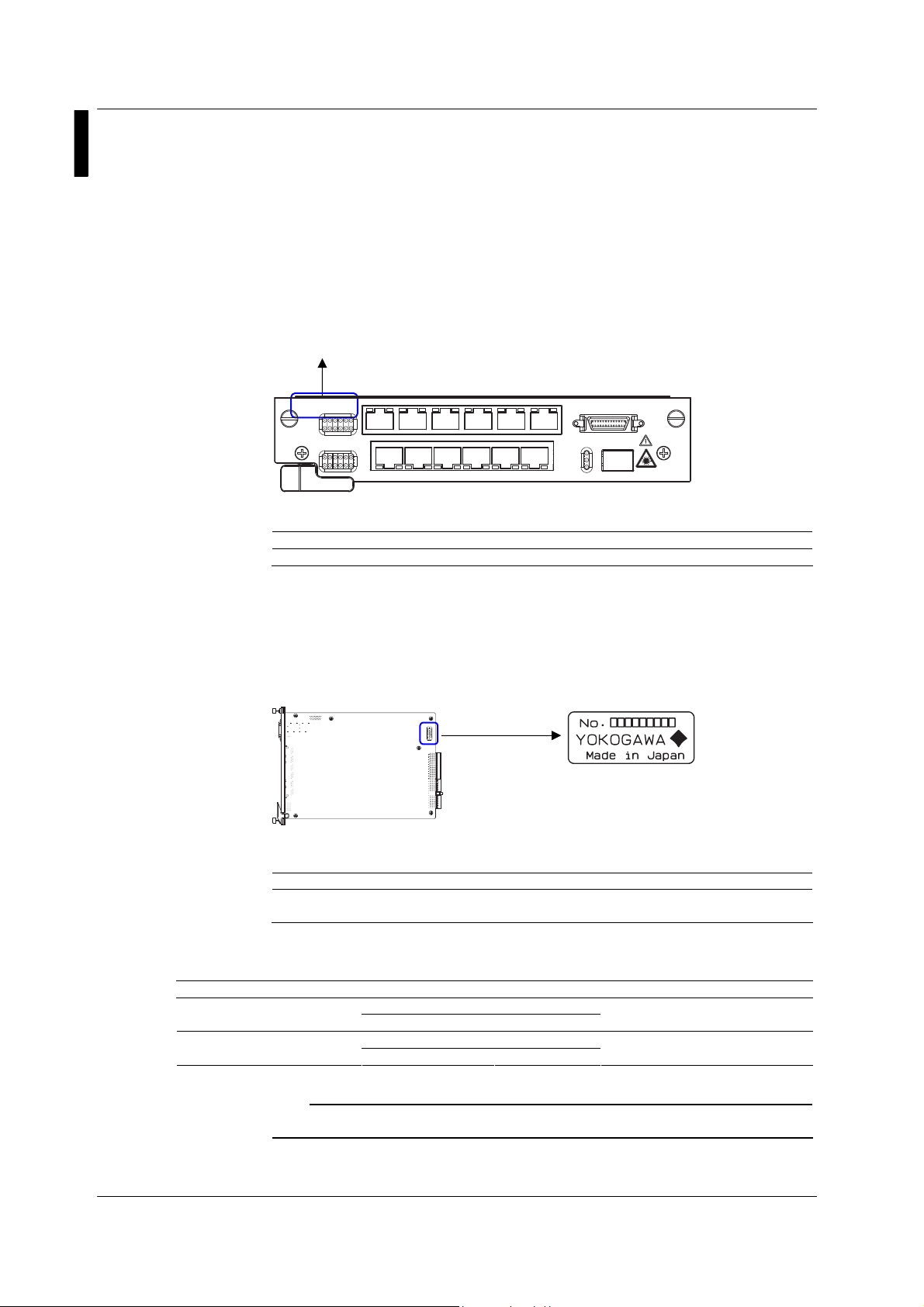
Check that the MODEL indicated on the front panel is what you ordered.
AE5523
1000BASE-T UNIT
• MODEL
• No. (Instrument No.)
Standard Accessories
The standard accessories below are supplied with the instrument.
Options (Sold Separately)
The interface modules below are available for purchase separately.
Name Model Manufacturer Notes
Module
Module
Note
AE5523
1000BASE-
PoE
LI
NK
Model Suffix Code Description
731010 - AE5523 1000BASE-T Unit
The instrument number is inscribed on the name plate at the bottom of the AE5523
unit.
When contacting the dealer from which you purchased the instrument, please give
them the instrument number.
Item Manual No. Quantity Notes
AE5523 1000BASE-T Unit User’s Manual IM731010-01E 1 This
Warranty applies only to interface modules that you purchase from
YOKOGAWA.
UN
T
1357911
2 4 6 8 1012
TX1R
XTX3R
XTX5R
XTX7R
XTX8R
XTX9R
XTX10R
IT
PoE
LI
NK
2
R
XTX4R
TX
XTX6R
TRF2816ANLB OPNEXT 1000BASE-SX SFP
FTRJ8519P1BNL Finisar
TRF5836ANLB OPNEXT 1000BASE-LX SFP
FTRJ1319P1BTL Finisar
XTX11R
XTX12R
X
PoE MONITO
R
SFP
LI
NK
TX
R
X
X
TXRX
13
LC connector, 0.85 µm, for
MMF
LC connector, 1.3 µm, for SMF
manual
ii IM 731010-01E
Page 4
Safety Precautions
The general safety precautions described herein must be observed during all phases of
operation. If the instrument is used in a manner not specified in this manual, the
protection provided by the instrument may be impaired. Yokogawa Electric
Corporation assumes no liability for the customer’s failure to comply with these
requirements.
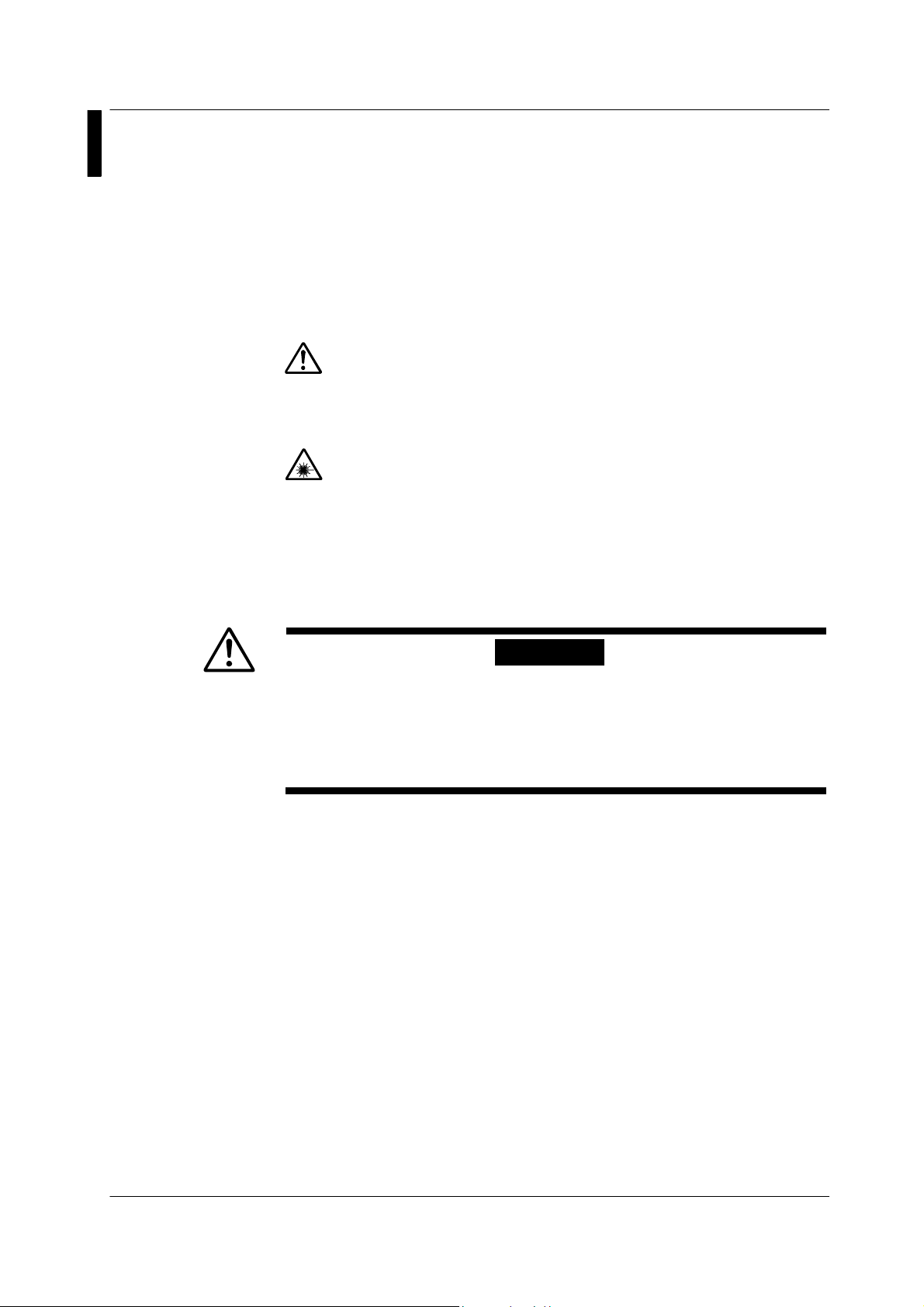
The following symbols are used on this instrument.
Warning: handle with care. Refer to the user’s manual or service manual.
This symbol appears on dangerous locations on the instrument which require
special instructions for proper handling or use. The same symbol appears in
the corresponding place in the manual to identify those instructions.
Hazard, radiation of laser apparatus
Make sure to comply with the precautions below. Not complying might result in injury or
death.
•
Do Not Operate in an Explosive Atmosphere
Do not operate the instrument in the presence of flammable liquids or vapors.
Operation in such an environment constitutes a safety hazard.
•
Do Not Touch Parts
Do not touch parts on the unit board. It may cause damage to the unit due to
shorting of the electric circuit or static electricity.
IM 731010-01E iii
WARNING
Page 5

Conventions Used in This Manual
Markings
The following markings are used in this manual.
Improper handling or use can lead to injury to the user or damage to
the instrument.
This symbol appears on the instrument to indicate that the user must
refer to the user's manual for special instructions. The same symbol
appears in the corresponding place in the user's manual to identify
those instructions. In the manual, the symbol is used in conjunction
with the word “WARNING” or “CAUTION.”
WARNING
CAUTION
Note Calls attention to information that is important for proper operation of
Calls attention to actions or conditions that could cause serious or
fatal injury to the user, and precautions that can be taken to prevent
such occurrences.
Calls attentions to actions or conditions that could cause light injury
to the user or damage to the instrument or user’s data, and
precautions that can be taken to prevent such occurrences.
the instrument.
iv IM 731010-01E
Page 6

Contents
Checking the Contents of the Package ..................................................... ii
Safety Precautions ....................................................................................iii
Conventions Used in This Manual............................................................ iv
Chapter 1 Functional Overview and Names of Parts
1.1 Functional Overview ...................................................................1-1
1.2 Front Panel.................................................................................1-2
1.3 PoE Monitor Connector ..............................................................1-3
Chapter 2 Operation
2.1 Installing the Unit ........................................................................2-1
2.2 Installing the Interface Module....................................................2-2
11
22
33
Chapter 3 Specifications
3.1 Interface .....................................................................................3-1
3.2 Functions....................................................................................3-2
3.3 General Specifications................................................................ 3-4
3.4 External Dimensions................................................................... 3-5
IM 731010-01E v
Page 7

Chapter 1 Functional Overview and Names of Parts
1.1 Functional Overview
The AE5523 is a unit for the AE5511 TrafficTesterPro that supports 10BASE-T,
100BASE-TX, and 1000BASE-T.
The functions of the AE5523 are listed below.
• Evaluation and test functions for IP network equipment
• Statistics function for each QoS (supports up to 8 flows)
• Sequence check function (lost packets, reordered packets, and duplicate packets)
• IPv6 emulation function (NDP and Ping6 auto response)
• PoE measurement functions
• Powered device (PD) emulation function
• Class declaration
• Line power detection function
• Evaluation of electrical characteristics (using a PoE monitor connector.
Connection of an external electric load device required)
• Basic measurement functions
• Traffic generation function
• Latency measurement function
• Bit error rate measurement function
• Multi user function (up to 8 users can connect simultaneously)
• Capture function (equipped with 1-MB capture memory for each port)
This instrument has functions allowing it to transmit frames at high loads from its
measurement ports. Incorrect operation can result in breakdown or
deterioration of network media or related devices. Sufficient care must be
taken when performing tests while connected to networks. Yokogawa does not
assume any responsibility for damages resulting from incorrect operation.
CAUTION
11
Functional Overview and Names of Parts
IM 731010-01E 1-1
Page 8

r
)
r
)
w
r
1.2 Front Panel
AE5523
1000BASE-
PoE
LI
NK
1357911
2 4 6 8 1012
Leve
Attachment scre
Name Description
LED (for RJ-45) PoE: Illuminates when PoE line power is detected.
RJ-45 connector A connector for 10/100/1000BASE-T.
PoE monitor
connector
LED (for SFP) LINK: Illuminates during line link up status.
SFP port A port for installing various SFP modules (need to be
Attachment screw Used to fix the unit in place after inserting it in the AE5511.
Lever Used to remove the unit from the AE5511.
TX1R
UN
IT
T
PoE
LI
NK
LED (for the RJ-45
XTX3X5R
R
TX
2
R
XTX4R
PoE monitor connecto
RJ-45 connecto
XTX7R
XTX9R
XTX11R
XT
XTX6R
XTX8R
XTX10R
XTX12R
X
PoE MONITO
LI
NK
TX
R
X
X
SFP
TXRX
13
R
SFP port
LED (for SFP
LINK: Illuminates during line link up status.
TX: Illuminates when transmitting data.
RX: Illuminates when receiving data.
Blinks during a self test.
A connector for monitoring the PoE line power status.
(See section 1.3)
TX: Illuminates when transmitting data.
RX: Illuminates when receiving data.
Blinks during a self test.
purchased separately).
Attachment
screw
1-2 IM 731010-01E
Page 9

1.3 PoE Monitor Connector
PoE measurement can be carried out by connecting the AE5523 to a PoE monitor.
Pin arrangement and pin assignments are shown below.
Pin Assignments of the PoE Monitor Connector
Pin No. 1 2 3 4 5 6 7 8 9 10 11 12 13
Signal Name FG V1 V2 V3 V4 V5 V6 V7 V8 V9 V10 V11 V12
Pin No. 14 15 16 17 18 19 20 21 22 23 24 25 26
Signal Name NC G1 G2 G3 G4 G5 G6 G7 G8 G9 G10 G11 G12
FG: Frame ground
NC: Not connected
V1 to V12: -48 V output
G1 to G12: Ground
Note
13
26 14
Pin Arrangement
•
Turn OFF the power when connecting/disconnecting the cable
Check that the AE5511 TrafficTesterPro is turned OFF when
connecting/disconnecting the PoE monitor cable. Connecting/Disconnecting
the cable with the power turned ON may damage the AE5523 electrically.
•
Do not short the terminals
If a PoE device is connected and the PoE setting is enabled, voltage is applied
between PoE monitor terminals (V1 and G1, V2 and G2, and so on).
Do not short the PoE monitor terminals. Doing so may cause malfunction.
Cables are not included in the package. Use the following connectors or their
equivalents.
• Plug: 54306-2619 (by Molex)
• Shell: 52370-2670 (by Molex)
1
CAUTION
11
Functional Overview and Names of Parts
IM 731010-01E 1-3
Page 10

Chapter 2 Operation
2.1 Installing the Unit
Installing the Unit
Install or remove the unit with the main power of the AE5511 turned OFF
•
(STANDBY LED: OFF and POWER LED: OFF). Otherwise, malfunction may
result.
Attach blank panels to unused AE5511 slots to prevent accidents.
•
1. Check that the main power of the AE5511 is turned OFF.
2. Align the unit with the slot guide of the AE5511 and insert it slowly toward the back of
the AE5511.
3. Press the panel section of the unit with your thumbs until the connectors on the unit
and AE5511 engage.
4. Fasten the two attachment screws of the unit to fix the unit in place.
Removing the Unit
Pull the lever
1. Check that the main power of the AE5511 is turned OFF.
2. Loosen the two attachment screws of the unit.
3. Pull the unit lever slowly toward you. The connectors disengage, and the unit
comes out from the AE5511.
4. Hold the attachment screw with each hand, and pull the unit slowly out from the
AE5511.
Unit
CAUTION
2
Operation
AE5511
IM 731010-01E 2-1
Page 11

2.2 Installing the Interface Module
Installing the SFP Module
Align the SFP module with the SFP module guide of the unit and insert the module
slowly into the unit. Press the module in firmly until the connectors engage.
Removing the SFP Module
Pull out the lever at the front, top section of SFP module and pull the lever toward you.
The connectors disengage, and the SFP module comes out from the unit.
Note
Be careful of static electricity when installing or removing the SFP module. If you
•
install or remove the module when static electricity is built up, it can cause
damage.
Do not install or remove the module with the cable connected. Doing so may
•
cause malfunction.
Pull out the lever
The SFP module can be installed or removed with the power turned ON.
CAUTION
2-2 IM 731010-01E
Page 12

Chapter 3 Specifications
3.1 Interface
Item Specifications
RJ-45
connector
SFP port
PoE monitor connector 26 pins (PoE voltage of each RJ-45 port can be monitored.)
*1: An SFP module option, sold separately, is required. See page ii for the SFP module option.
*1
Standard 10BASE-T
Number of ports 12 ports
Link speed 10 Mbps/100 Mbps/1000 Mbps
Duplex Full duplex/half duplex (fixed to full duplex mode when 1000BASE-T is
Flow control ON/OFF setting (complies with IEEE802.3x)
MDI/MDI-X MDI (straight)/MDI-X (cross)/auto setting
LED
Standard 1000BASE-SX
Number of ports 1 port
Link speed 1000 Mbps
Duplex Fixed to full duplex
Auto negotiation ON/OFF setting (flow control negotiation only)
Flow control ON/OFF selectable (complies with IEEE802.3x)
LED
(Complies with
100BASE-TX
1000BASE-T
selected)
ON/OFF setting Auto negotiation
Variable advertisement level
TX (green) Illuminates during data transmission operation. Blinks
RX (green) Illuminates during data reception operation. Blinks
LINK (green) Illuminates during line link up status. Blinks during a
PoE (green) Illuminates when PoE is detected. Blinks during a
1000BASE-LX
Tx (green) Illuminates during data transmission operation. Blinks
Rx (green) Illuminates during data reception operation. Blinks
LINK (green) Illuminates during line link up status. Blinks during a
IEEE802.3i)
(Complies with
IEEE802.3u)
(Complies with
IEEE802.3ab)
during SELFTEST.
during a self-test.
self-test.
self-test.
(Complies with IEEE802.3z)
(Complies with IEEE802.3z)
during a self-test.
during a self-test.
self-test.
Complies with PoE (IEEE802.3af)
Complies with PoE (IEEE802.3af)
Complies with PoE (IEEE802.3af)
33
Specifications
IM 731010-01E 3-1
Page 13

3.2 Functions
Traffic Generation Function
Item Specifications
Transmit
Receive
3-2 IM 731010-01E
Transmission
mode
Transmitted
data (fixed)
Transmitted
data (variable)
function
Link up/down
control
function
Filter
Transmit
statistics
display
Receive
statistics
display
QoS
statistics
display
Transmission
mode
Defined no. of
frames
Frame length 48–9999 bytes (fixed frame length)
Defined
frames
Increment MAC address increment can be set
Payload
setting
Errors CRC error, symbol error, IP header checksum error, TCP
No. of variable
fields
Variable size 128 bit width (can be divided in to 4 fields in unit of 32 bits)
Variable field
offset
Var iable
method
Frame length Range: 64 to 9999 bytes (set increment, decrement, or random)
Manual One frame can be sent manually. Insert frame
Periodic Sends insert frames periodically. Period setting: 1 ms to 600 s
Manual Generate link up or link down through manual operation
Periodic Repetitively generate link up and link down Min. period: 10 s.
MAC filter Receive frames only from a specified destination MAC address,
VLAN filter VLANID, TPID, and Priority can be set
Pattern filter Two filters each consisting of 6-byte comparison and mask
Normal No. of frames, no. of bytes, rate (%), rate (frame/s), rate
Error
Normal No. of frames, no. of bytes, rate (%), rate (frame/s), rate
Error
Statistics
mode
Statistics
channel
Statistical
items
QoS statistical
filter
Constant rate: %, µs, ns, bit (48 bits minimum), frame/s, or bps Rate
Burst (interval setting: 1 µs to 1 s)
Continuous, single shot (specify the number of transmission
frames), time designation (in unit of s)
128 frames/port max. (one frame is used for the insert frame)
IPv4, IPv6, IPX, UDP, TCP, IGMP, ICMP, ICMPv6, ARP, PAUSE
custom (with MAC), custom (without MAC)
tag (VLAN tag, MPLS, EoMPLS)
Set in the range of 00 to FFh. Set the size to Byte, Word, or
LongWord.
checksum error, UDP checksum error, ICMP checksum error,
ICMPv6 checksum error, and IGMP checksum error
Up to 4 fields can be varied simultaneously
0 to 9990 bytes
Increment, random, or table reference (max. no. of ref. tables:
1024)
(1 ms resolution)
Max. period: 3600 s. Step: 1 s
source MAC address, or unicast frames
patterns and offset can be set. AND or OR logic, pass, or
reject on the two filters can be set.
(byte/s), rate (bps), no. of insert frames, and no. of reply frames
No. of error frames, no. of CRC error frames, no. of undersize
frames, no. of oversize frames, and no. of symbol error frames
Error frames (frame/s), CRC errors (frame/s), undersize
(frame/s), oversize (frame/s), and symbol errors (frame/s)
(byte/s), rate (bps), no. of pause frames, and no. of collisions
detected
No. of error frames, no. of CRC error frames, no. of undersize
frames, no. of oversize frames, no. of alignment error frames,
no. of symbol error frames, and no. of late collisions detected
Error frames (frame/s), CRC errors (frame/s), undersize
(frame/s), oversize (frame/s), alignment error (frame/s), and
symbol errors (frame/s)
For each flow (frame pattern comparison) and for each frame
length
8 channels
Total (frame), total (byte), rate (frame/s), rate (%), and rate (bps)
Two filters each consisting of 32-bit comparison and mask
patterns and offset can be set.
Frame length can be specified.
Page 14

3.2 Functions
Latency Measurement Function
Item Specifications
Measurement item
IFG Measures the max., min., and average IFG (Inter Frame Gap)
(unit: µs)
Packet latency Measures the max., min., and average packet delay (unit: µs)
Packet delay for
each QoS
Measures the packet delay for each flow (8 channels)
Bit Error Rate Measurement Function
Item Specifications
Transmit
Receive Displayed statistical items Bit error rate, bit error frame, bit error count. sync loss, checked
Transmission
mode
Transmitted
data (fixed)
Var iable
frame length
Transmission
mode
Defined no. Of
frames
Frame length 64–9999 bytes (fixed frame length)
Test pattern
(payload)
Var iable
Method
Frame length 64 to 9999 bytes
Constant rate: %, µs, ns, bit (48 bits minimum), frame/s, or bps Rate
Burst (interval setting: 1 µs to 1 s)
Continuous, single shot (specify the number of transmission
frames), time designation (in unit of s)
1 frame/port (64 to 9999 bytes)
PN15
Increment, decrement, and random
byte, bit error (bps), bit error frame (frame/s), sync loss/s,
checked byte/s, bit error insert, and bit error insert frame
Capture Function
Item Specifications
Capture function
Capture size 1 MB per port
Frame slice function Select from four types: 64, 256, 2048, or 9999 bytes
Filter function • Pattern filter
Trigger function
Displayed items Frame No., time stamp, frame status, frame length, destination
File type AE5511 format, Etherreal (tcpdump) format, and CSV format
Comparison pattern: 6 bytes × 2, mask pattern: 6 bytes × 2
Offset: 0 to 58 bytes
• Capture only normal frames, error frames, layer 1 state
change, or insert frames
• Normal frame pattern
Comparison pattern: 6 bytes × 2, mask pattern: 6 bytes × 2
Offset: 0 to 58 bytes
• Completion of the insert frame transmission
• Error frames
CRC error, undersize, oversize, symbol error, sequence error,
bit error, all error frame, link up, and link down
Trigger position (select from three types)
Top, center, or end
MAC address, source MAC address, payload data (hex display)
Other Functions
Item Specifications
PoE measurement
function
Sequence check
function
Alarm log function
Transmit clock
variable function
IM 731010-01E 3-3
PD emulation Sequence emulation conforming to IEEE802.3af
Class declaration Declare default class or arbitrary class
Line power detection Detects the ON/OFF status of power feeding
Types of errors
detected
IPv4 ARP reply, Ping reply, and MAC address auto learn Emulation function
IPv6 NDP address resolution function, PING6 reply function, and auto
Alarm items Packet error, reception rate error, packet delay error, IFG error,
No. of recorded logs Up to 1000 events (log recorded at 1-s intervals min.)
Range: ±100 ppm. Resolution: 1 ppm. Accuracy: 5 ppm ± 1
Packet loss, max. burst packet loss, reordered packets, and
duplicate packets
address generation function
and layer 1 state change
digits
33
Specifications
Page 15

3.3 General Specifications
Item Specifications
Voltage 5 VDC or 3.3 VDC Power supply
weight
environment
Power
consumption
Dimensions H40 × W200 × D260 [mm] (projections excluded) Dimensions and
Weight Approx. 1 kg
Temperature 5 to 40°C Operating
Humidity 35 to 85%
47 W or less
3-4 IM 731010-01E
Page 16

3.4 External Dimensions
Unit: mm
Tolerance: ±3%
33
Specifications
260
732
.
13
200
7
.
287
40
IM 731010-01E 3-5
 Loading...