

Yealink DECT Multi-Cell System Administrator’s Guide

Copyright
Copyright © 2019 YEALINK(XIAMEN) NETWORK TECHNOLOGY
Copyright © 2019 Yealink (Xiamen) Network Technology CO., LTD. All rights reserved. No parts of this publication may
be reproduced or transmitted in any form or by any means, electronic or mechanical, photocopying, recording, or otherwise, for any purpose, without the express written permission of Yealink (Xiamen) Network Technology CO., LTD.
Under the law, reproducing includes translating into another language or format.
When this publication is made available on media, Yealink (Xiamen) Network Technology CO., LTD. gives its consent to
downloading and printing copies of the content provided in this file only for private use but not for redistribution. No
parts of this publication may be subject to alteration, modification or commercial use. Yealink (Xiamen) Network Technology CO., LTD. will not be liable for any damages arising from use of an illegally modified or altered publication.
Trademarks
Yealink®, the logo and the name and marks is trademark of Yealink (Xiamen) Network Technology CO., LTD, which are
registered legally in China, the United States, EU (European Union) and other countries.
All other trademarks belong to their respective owners. Without Yealink’s express written permission, recipient shall not
reproduce or transmit any portion hereof in any form or by any means, with any purpose other than personal use.
End User License Agreement
This End User License Agreement ("EULA") is a legal agreement between you and Yealink. By installing, copying or otherwise using the Products, you: (1) agree to be bounded by the terms of this EULA, (2) you are the owner or an authorized user of the device, and (3) you represent and warrant that you have the right, authority and capacity to enter into
this agreement and to abide by all its terms and conditions, just as if you had signed it. The EULA for this product is
available on the Yealink Support page for the product.
Patent Information
China, the United States, EU (European Union) and other countries are protecting one or more patents of accompanying products and/or patents being applied by Yealink.
Customer Feedback
We are striving to improve our documentation quality and we appreciate your feedback. Email your opinions and comments to DocsFeedback@yealink.com.
Technical Support
Visit Yealink WIKI (http://support.yealink.com/) for the latest firmware, guides, FAQ, Product documents, and more.
For better service, we sincerely recommend that you use Yealink Ticketing system (https://ticket.yealink.com) to submit
all your technical issues.

GNU GPL INFORMATION
Yealink device firmware contains third-party software under the GNU General Public License (GPL). Yealink uses software under the specific terms of the GPL. Please refer to the GPL for the exact terms and conditions of the license.
The original GPL license, source code of components licensed under GPL and used in Yealink products can be downloaded online: http://www.yealink.com/onepage_83.html.

Table of Contents
Table of Contents
Table of Contents
DECT IP Multi-Cell System Introduction
Components of the DECT IP Multi-Cell System
Deployments of the DECT IP Multi-Cell System
Related Documentations
First Steps
Preparing to Use the Multi-Cell System
Assigning the Device Role
Registering the First Handset to the W80B Device
Finding the IP Address of the W80B
Configuring the System via Web User Interface
Accessing Web User Interface
Navigating the Web User Interface
Logging out of the Web User Interface
Initialization Instructions
Initialization Process Overview
Loading the ROM File
Configuring the VLAN
Querying the DHCP (Dynamic Host Configuration Protocol) Server
Contacting the Provisioning Server
Updating Firmware
Downloading the Resource Files
Verifying Startup
1
12
12
13
14
15
15
16
16
17
17
18
18
18
19
19
19
19
19
19
20
20
20
Setting up the Base Stations
Base Mode
Base Mode Configuration
LED Indicators on the W80B
Base Station Pre-registration
Base Station Pre-registration Configuration
Manually Registering Base Stations to the DM
DM IP
DM IP Configuration
Base Station Settings
Base Station Settings Configuration
Managing the Connected Base Stations
Base Station Synchronization
Synchronization Planning
Managing the Handsets
Registering Handsets via Web User Interface
21
21
21
21
23
23
24
24
24
25
25
26
27
28
29
29
1

Administrator’s Guide for DECT Multi-Cell System
IPUI Registration
Obtaining the IPUI Code of the Handset
Notes on Configuring IPUI
IPUI Code Configuration
Handset Registration Center
Registering Handsets Time-Controlled
Registering Handsets at Once
Manually Closing the Registration
De-registering a Handset
Account Settings
Account Registration
Supported Accounts
SIP Server Template Configuration
Accounts Registration Configuration
Registration Settings Configuration
Outbound Proxy in Dialog
Outbound Proxy in Dialog Configuration
Server Redundancy
Behaviors When Working Server Connection Fails
Registration Method of the Failover/Fallback Mode
Fallback Server Redundancy Configuration
Failover Server Redundancy Configuration
SIP Server Name Resolution
SIP Server Name Resolution Configuration
Static DNS Cache
Behave with a Configured DNS Server
Static DNS Cache Configuration
Number of Simultaneous Outgoing Calls
Number of Simultaneous Outgoing Calls Configuration
Number of Active Handsets Per Base
Number of Active Handsets Per Base Configuration
29
29
30
30
30
31
31
31
32
33
33
33
33
35
37
39
39
40
41
42
42
42
44
44
45
46
46
49
49
50
50
Network Configurations
IPv4 Network Settings
IPv4 Configuration
DHCP Option for IPv4
Supported DHCP Option for IPv4
DHCP Option 66, Option 43 and Custom Option
DHCP Option 42 Option 2
DHCP Option 12
DHCP Option 12 Hostname Configuration
DHCP Option 60
DHCP Option 60 Configuration
VLAN
LLDP Configuration
2
51
51
51
53
53
53
54
54
54
54
55
55
55

Table of Contents
CDP Configuration
Manual VLAN Configuration
DHCP VLAN Configuration
VLAN Setting Configuration
Real-Time Transport Protocol (RTP) Ports
RTP Ports Configuration
Network Address Translation (NAT)
NAT Traversal Configuration
Keep Alive Configuration
Rport Configuration
SIP Port and TLS Port Configuration
VPN
VPN Related Files
VPN Configuration
Quality of Service (QoS)
Voice and SIP QoS Configuration
TR-069 Device Management
Supported RPC Methods
TR-069 Configuration
802.1x Authentication
802.1x Authentication Configuration
56
56
57
58
58
58
59
59
62
63
63
64
64
64
65
65
66
66
67
68
68
Web Statistics
Base Station Group
Base Station Statistics
Cluster Graph Statistics
Viewing Base Station Group Statistics
All Calls
All Calls Statistics
Viewing All Calls Statistics
Base Stations Calls
Base Stations Calls Statistics
Viewing Base Stations Calls Statistics
Handsets Calls
Handsets Calls Statistics
Viewing Handsets Calls Statistics
Abnormal Calls
Abnormal Calls Statistics
Viewing Abnormal Calls Statistics
Upgrade Information
Upgrade Information Statistics
Viewing Upgrade Information Statistics
DECT Signal
DECT Signal Statistics
Viewing DECT Signal Statistics
71
71
71
72
73
74
75
75
76
76
77
77
77
78
79
79
79
80
80
81
82
82
82
3

Administrator’s Guide for DECT Multi-Cell System
Phone Provisioning
Boot Files, Configuration Files, and Resource Files
Boot Files
Common Boot File
MAC-Oriented Boot File
Boot File Attributes
Customizing a Boot File
Configuration Files
Common CFG File
MAC-Oriented CFG File
MAC-local CFG File
Configuration File Customization
Customizing a Configuration File
Configuration File Attributes
Resource Files
Supported Resource Files
Files Download Process
Provisioning Methods
Provisioning Methods Priority
Web User Interface
Quick Login Configuration
Web Server Type Configuration
Central Provisioning
Auto Provisioning Settings Configuration
Setting Up a Provisioning Server
Supported Provisioning Protocols
Provisioning Protocols Configuration
Supported Provisioning Server Discovery Methods
PnP Provision Configuration
DHCP Provision Configuration
Static Provision Configuration
Configuring a Provisioning Server
Keeping User’s Personalized Settings after Auto Provisioning
Keeping User’s Personalized Settings Configuration
Auto Provisioning Flowchart for Keep User’s Personalized Configuration Settings
Example: Keeping User’s Personalized Settings
Clearing User's Personalized Configuration Settings
Custom Handset Related Configurations
84
84
84
84
85
85
85
86
86
86
86
87
87
87
87
88
88
89
89
90
90
91
92
93
98
98
98
99
99
99
100
101
101
101
103
103
104
104
Security Features
User and Administrator Identification
User and Administrator Identification Configuration
User Access Level Configuration
Auto Logout Time
Auto Logout Time Configuration
4
106
106
106
107
108
108

Table of Contents
Base PIN
Base PIN Configuration
Emergency Number
Emergency Number Configuration
Transport Layer Security (TLS)
Supported Cipher Suites
Supported Trusted and Server Certificates
Supported Trusted Certificates
TLS Configuration
Secure Real-Time Transport Protocol (SRTP)
SRTP Configuration
Encrypting and Decrypting Files
Configuration Files Encryption Tools
Configuration Files Encryption and Decryption
Encryption and Decryption Configuration
Example: Encrypting Configuration Files
Incoming Network Signaling Validation
Incoming Network Signaling Validation Configuration
Firmware Upgrade
Firmware for Each Phone Model
Firmware Upgrade Configuration
Upgrading Multiple Handsets via Web User Interface
108
108
109
109
109
110
111
111
113
115
117
117
117
118
118
119
121
121
123
123
123
125
Audio Features
Alert Tone
Alert Tone Configuration
Ringer Device
Ringer Device Configuration
Tones
Supported Tones
Tones Configuration
Audio Codecs
Supported Audio Codecs
Audio Codecs Configuration
Packetization Time (PTime)
Supported PTime of Audio Codec
PTime Configuration
Early Media
Early Media Configuration
Acoustic Clarity Technology
Background Noise Suppression (BNS)
Automatic Gain Control (AGC)
Voice Activity Detection (VAD)
VAD Configuration
Comfort Noise Generation (CNG)
127
127
127
127
128
128
128
129
131
131
132
133
134
134
135
135
135
135
135
136
136
136
5

Administrator’s Guide for DECT Multi-Cell System
CNG Configuration
Jitter Buffer
Jitter Buffer Configuration
DTMF
DTMF Keypad
Transmitting DTMF Digit
Transmitting DTMF Digit Configuration
Suppress DTMF Display
Suppress DTMF Display Configuration
Handset Customization
Power LED Indicator of Handset
Power LED Indicator of Handset Configuration
Handset Keypad Light
Handset Keypad Light Configuration
Handset Backlight
Handset Backlight Configuration
Handset Wallpaper
Handset Wallpaper Configuration
Handset Screen Saver
Handset Screen Saver Configuration
Language
Supported Languages
Language Display Configuration
Language for Web Display Customization
Customizing a Language Pack for Web Display
Custom Language for Web Display Configuration
Time and Date
Time Zone
NTP Settings
NTP Configuration
DST Settings
Auto DST File Attributes
Customizing Auto DST File
DST Configuration
Time and Date Manually Configuration
Time and Date Format Configuration
Date Customization Rule
Input Method
Input Method Configuration
Search Source List in Dialing
Search Source File Customization
Search Source File Attributes
Customizing Search Source File
Search Source List Configuration
136
136
137
137
138
138
138
140
140
141
141
141
142
142
142
143
143
144
144
144
145
145
145
146
146
147
148
148
151
151
153
153
154
154
156
156
158
159
159
160
160
160
161
161
6

Table of Contents
Call Display
Call Display Configuration
Display Method on Dialing
Display Method on Dialing Configuration
Key As Send
Key As Send Configuration
Recent Call Display in Dialing
Recent Call in Dialing Configuration
Warnings Display
Warnings Display Configuration
Advisory Tones
Advisory Tones Configuration
Shortcut Customization
Shortcut Customization Configuration
Directory
Local Directory
Local Contact File Customization
Local Contact File Elements and Attributes
Customizing Local Contact File
Local Contact Files and Resource Upload
Lightweight Directory Access Protocol (LDAP)
LDAP Attributes
LDAP Configuration
Remote Phone Book
Remote Phone Book File Customization
Remote Phone Book File Elements
Customizing Remote Phone Book File
Remote Phone Book Configuration
Example: Configuring a Remote Phone Book
Shared Directory
Shared Directory Configuration
Shared Contact File Customization
Shared Contact File Elements and Attributes
Customizing Shared Contact File
XML Phonebook
XML Phonebook Configuration
Directory Search Settings
Directory Search Settings Configuration
163
163
164
164
164
164
165
165
165
165
165
166
167
167
169
169
169
169
170
170
170
170
171
176
176
176
177
177
178
178
179
179
179
180
180
180
181
181
Call Log
Call Log Display
Call Log Configuration
Call Features
Dial Plan
182
182
182
183
183
7

Administrator’s Guide for DECT Multi-Cell System
Basic Regular Expression Syntax for Four Patterns
Replace Rule File Customization
Replace Rule File Attributes
Customizing the Replace Rule File
Dial Now File Customization
Dial Now File Attributes
Customizing the Dial Now File
Replace Rule Configuration
Dial Now Configuration
Area Code Configuration
Block Out Configuration
Example: Adding Replace Rules Using a Replace Rule File
Emergency Dialplan
Emergency Dialplan Configuration
Off Hook Hot Line Dialing
Off Hook Hot Line Dialing Configuration
Call Timeout
Call Timeout Configuration
Anonymous Call
Anonymous Call Configuration
Call Number Filter
Call Number Filter Configuration
Auto Answer
Auto Answer Configuration
Anonymous Call Rejection
Anonymous Call Rejection Configuration
Call Waiting
Call Waiting Configuration
Do Not Disturb (DND)
DND Settings Configuration
DND Feature Configuration
DND Configuration
DND Synchronization for Server-side Configuration
Call Hold
Call Hold Configuration
Call Forward
Call Forward Settings Configuration
Call Forward Feature Configuration
Call Forward Configuration
Call Forward Synchronization for Server-side Configuration
Call Transfer
Call Transfer Configuration
Conference
Conference Type Configuration
Network Conference Configuration
184
184
184
185
185
185
185
185
186
187
188
189
189
189
191
192
192
192
193
193
194
194
194
195
195
195
196
196
197
197
198
198
199
199
199
200
200
201
201
204
205
205
206
206
206
8

Table of Contents
End Call on Hook
End Call on Hook Configuration
Advanced Features
Call Park and Retrieve
Call Park and Retrieve Configuration
Shared Line
Shared Call Appearance (SCA) Configuration
SCA Configuration
Voice Mail
MWI for Voice Mail Configuration
General Features
Line Identification Presentation
CLIP and COLP Configuration
Return Code for Refused Call
Return Code for Refused Call Configuration
Accept SIP Trust Server Only
Accept SIP Trust Server Only Configuration
100 Reliable Retransmission
100 Reliable Retransmission Configuration
SIP Session Timer
SIP Session Timer Configuration
Session Timer
Session Timer Configuration
Reboot in Talking
Reboot in Talking Configuration
Reserve # in User Name
Reserve # in User Name Configuration
Busy Tone Delay
Busy Tone Delay Configuration
207
207
208
208
208
209
209
209
210
210
213
213
213
215
215
215
215
216
216
217
217
218
218
219
219
219
220
220
220
Configuration Parameters
BroadSoft Parameters
BroadSoft Settings
Broadsoft XSI
Broadsoft Network Directory
Broadsoft Call Park
BroadSoft Call Waiting Sync
BroadSoft DND and Forward Sync
Ethernet Interface MTU Parameter
SIP Settings Parameters
Call Settings Parameters
Troubleshooting Methods
All Base Diagnostics
Diagnostics File Type and Naming Rules
222
222
222
222
224
227
228
228
229
229
230
232
232
232
9

Administrator’s Guide for DECT Multi-Cell System
All Base Diagnostics Configuration
Log Files
Local Logging
Local Logging Configuration
Exporting the Log Files to a Local PC
Viewing the Log Files
Syslog Logging
Syslog Logging Configuration
Viewing the Syslog Messages on Your Syslog Server
Resetting Phone and Configuration
Resetting the IP phone to Default Factory Settings
Resetting the IP phone to Custom Factory Settings
Custom Factory Configuration
Deleting the Custom Factory Settings Files
Packets Capture
Capturing the Packets via Web User Interface
Capturing the Packets in Enhanced Way
Capturing the Packets in Normal Way
Watch Dog
Watch Dog Configuration
Analyzing Configuration Files
Exporting CFG Configuration Files from Phone
Importing CFG Configuration Files to Phone
Configuration Files Import URL Configuration
Exporting BIN Files from the Phone
Importing BIN Files from the Phone
BIN Files Import URL Configuration
Exporting All the Diagnostic Files
Device Status
Viewing Device Status
Phone Reboot
Rebooting the IP Phone Remotely
Notify Reboot Configuration
Rebooting the Device via Web User Interface
232
234
234
234
237
237
238
238
241
241
242
242
242
243
243
243
243
244
244
244
245
245
245
246
246
246
246
246
247
247
247
247
248
248
Troubleshooting Solutions
IP Address Issues
The device does not get an IP address
Time and Date Issues
Display time and date incorrectly
Phone Book Issues
Difference between a remote phone book and a local phone book
Audio Issues
Increasing or decreasing the volume
Get poor sound quality during a call
10
249
249
249
249
249
249
249
250
250
250

Table of Contents
There is no sound when the other party picks up the call
Play the local ringback tone instead of media when placing a long-distance number without plus 0
Firmware and Upgrading Issues
Fail to upgrade the phone firmware
Verifying the firmware version
The IP phone does not update the configurations
System Log Issues
Fail to export the system log to a provisioning server (FTP/TFTP server)
Fail to export the system log to a syslog server
Password Issues
Restore the administrator password
The web screen displays "Default password is in use. Please change!"
Power and Startup Issues
Both PoE cable and power adapter is connected to the phone
The power LED indicator has no lights
Other Issues
The difference among user name, register name, and display name
On code and off code
The difference between RFC 2543Hold enabled and disabled
How does the DM configuration changes take effect when the handset is in the call?
Base Issue
Why doesn’t the power indicator on the base station light up?
Why doesn’t the network indicator on the base station slowly flash?
Handset Issues
How to check which area the handset is used for?
Register Issue
Why cannot the handset be registered to the base station?
Display Issue
Why does the handset prompt the message “Not Subscribed”?
Why does the handset prompt the message “Not in Range” or “Out Of Range”?
Why does the handset prompt the message “Network unavailable”?
Why does the handset display “No Service”?
Upgrade Issue
Why doesn’t the DECT IP phone upgrade firmware successfully?
250
250
250
250
251
251
251
251
251
251
251
252
252
252
252
252
252
252
252
253
254
254
254
254
254
254
254
254
254
255
255
255
255
255
Appendix
RFC and Internet Draft Support
Menu Structure Overview
256
256
259
11
DECT IP Multi-Cell System Introduction
DECT IP Multi-Cell System Introduction
The DECT IP multi-cell system is used for connecting multiple DECT base stations to a VoIP PBX. It supports the roaming
& handover feature, and provides a wider DECT signal coverage, and more handsets and simultaneous calls than the
single-cell.
Topics
Components of the DECT IP Multi-Cell System
Deployments of the DECT IP Multi-Cell System
Related Documentations
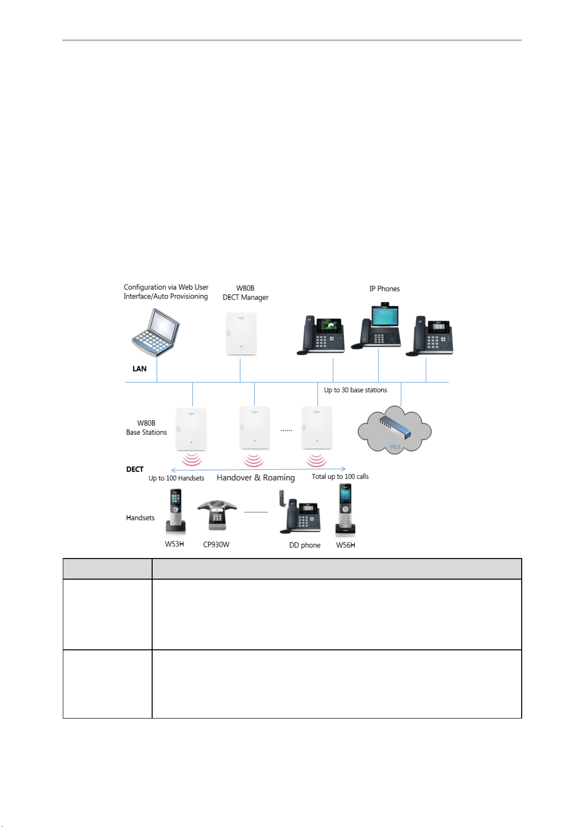
Components of the DECT IP Multi-Cell System
The following illustration shows the components of the DECT IP multi-cell system and the way the system is embedded
in the IP phone environment:
Components Description
Management unit for a group of base stations. At least one DECT manager must be used for
W80B DECT Manager
(sometimes just
referred to as DM)
W80B Base Stations
each installation.
• Manages base stations synchronization within the clusters.
• Enables the account registration and centrally stores the account configuration.
• Enables centralized configuration and deployment.
Up to 30 base stations can be supported by one DECT manager.
• Provide cell site DECT features.
• Provide media processing from handsets directly towards PBX.
• Provide connection channels for the handsets, the number depends on various factors such
as the approved bandwidth and the device role.
12
Administrator’s Guide for DECT Multi-Cell System
Components Description
Up to 100 handsets can be supported by one DECT manager. Up to 100 DECT calls can be made
Handsets
(Mobile Devices)
PBX
simultaneously for VoIP call.
Subscribers can accept or initiate calls in all base stations with their handsets (Roaming), and
can also switch handsets DECT connection between the base stations during a call (Handover).
A handover is only possible if base stations are synchronized.
IP PBX or Provider with VoIP (SIP) connections.
• Establishes the connection to a public phone network.
• Enables the centralized management of phone connections, remote phone book, and voice
mail.
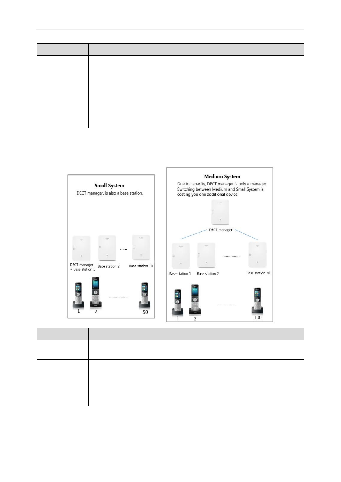
Deployments of the DECT IP Multi-Cell System
The DECT IP multi-cell system can be deployed in the multi-story office building, supermarket, store, warehouse, hotel,
and so on.
Device Small System Medium System
W80B DECT Manager
W80B Base Stations
Handsets
(Mobile Devices)
13
DECT manager and base station on the same
device.
Up to 10
Base station functionality can be activated on
the DECT manager device.
Up to 50 Up to 100 per DECT manager
At least one
Up to 30 per DECT manager

DECT IP Multi-Cell System Introduction
Related Documentations
The following related documents are available:
l Quick Start Guide, describes how to install the base station and obtain the device's IP address.
l User Guide, describes how to configure and use the basic and advanced features available in the DECT multi-cell sys-
tem.
l Deployment Guide, explains the necessary preparatory work for the installation and describes how to carry out meas-
urements in order to find the best positions for your base stations.
For support or service, please contact your Yealink reseller or go to Yealink Technical Support online: http://sup-
port.yealink.com/.
Read the Yealink Products Regulatory Notices guide for all regulatory and safety guidance.
14
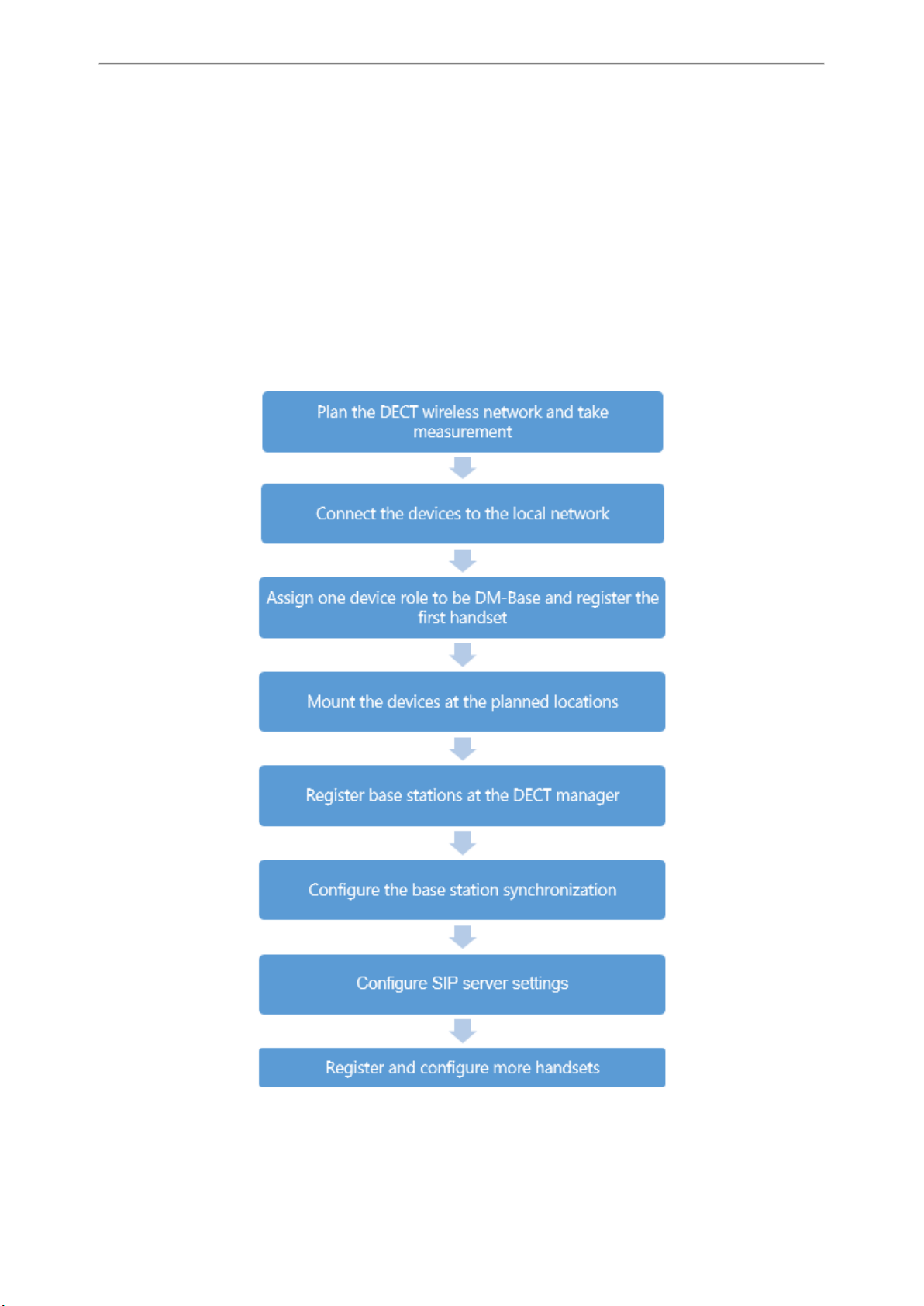
First Steps
First Steps
This chapter provides the information you need to prepare to configure your multi-cell system at the DECT manager.
Topics
Preparing to Use the Multi-Cell System
Assigning the Device Role
Registering the First Handset to the W80B Device
Finding the IP Address of the W80B
Configuring the System via Web User Interface
Preparing to Use the Multi-Cell System
15
Administrator’s Guide for DECT Multi-Cell System
Assigning the Device Role
All W80B devices are configured as the role of "base station" out of box. To set up the DECT multi-cell system, at least
one device must be configured as DM.
The W80B device supports the following three roles:
l Base: The device only works as a base station. You can configure the IP address of the DM via the web user interface
or RPS.
l DM: The device only works as a DECT manager.
l DM-Base: The device works as a DECT manager and a base station. Only in this mode can you register a handset to
the DECT manager.
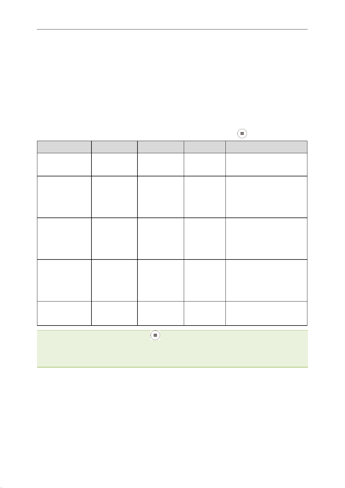
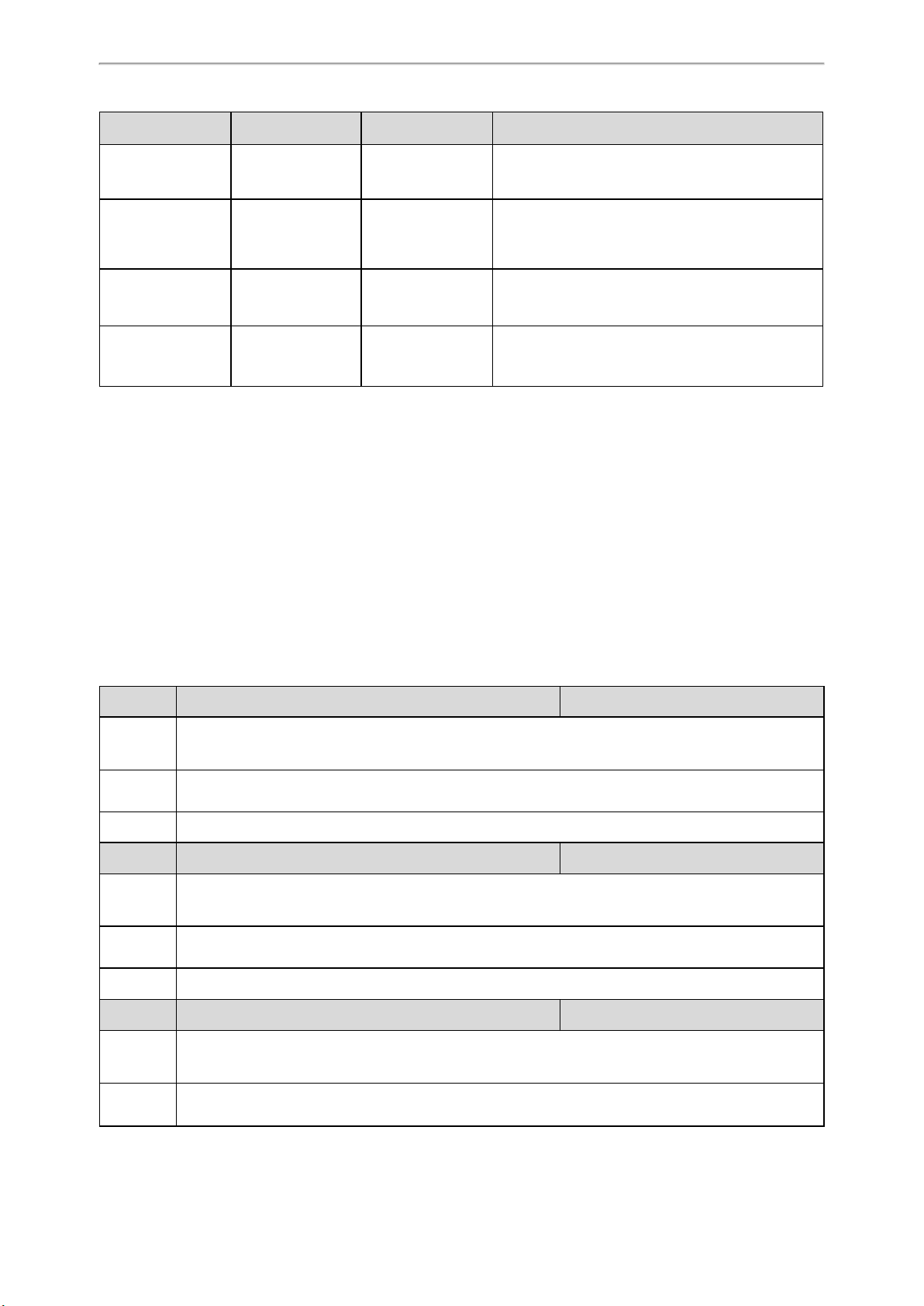
The following table describes how to change the role of the device using the device key on the front side.
Action LAN LED ROLE LED DECT LED Description
Long press the device
key for about 10
seconds.
Press the device key
once briefly.
Press the device key
twice briefly.
Press the device key
three times briefly.
Press the device key
four or more times
briefly.
Slowly flashing
green(1s)
Slowly flashing
green(1s)
Green Orange Green
Green Orange Off
Green Green Green
Fast flashing green
(0.5s)
Fast flashing green
(0.5s)
Slowly flashing
green(1s)
Fast flashing
green(0.5s)
The device is in the switching
mode.
The device is switched to the DM-
Base role.
Note: The device will reboot after 3
seconds to make the change take
effect.
The device is switched to the DM
role.
Note: The device will reboot after 3
seconds to make the change take
effect.
The device is switched to the Base
role.
Note: The device will reboot after 3
seconds to make the change take
effect.
The device returns to the switching
mode after the three LEDs fast flash
green three times.
Note: In the Base role, you can press the device key on the W80B three times quickly in one second to switch to the
DM-Base role.
When you change the role of the device, the time interval between each button press should be less than 3 seconds. The
device will return to the original role after 30 seconds of inactivity in the switching mode.
The device will not reboot if you switch back to the current role.
Registering the First Handset to the W80B Device
You can quickly register a handset to a W80B device to check the IP address of the DM at the beginning of the system
deployment.
Before You Begin
16

First Steps
l The W80B device role is DM-Base, and no handsets have been registered to the device.
l Long press the device key on the W80B till the DECT LED indicator flashes to set the device to the registration
mode. You can only register one handset to the W80B using this method.
Procedure
1. When the handset prompts "Unregistered!" on its LCD screen, do one of the following:
l Press the Reg soft key on the handset to register quickly.
l Press OK > Register Handset and then select the desired base to register the handset.
You need to enter the base PIN (default: 0000) after a base is found.
After the handset is registered successfully, the handset prompts “Handset Subscribed” on its LCD screen.
Tip: If the handset LCD screen does not prompt “Unregistered!”, press the OK key to enter the main menu and select Set-
tings > Registration > Register Handset to register the handset.
Related Topics
Assigning the Device Role
Registering Handsets via Web User Interface
Finding the IP Address of the W80B
After registering a handset to the W80B device, you can fast check the IP address of the device for accessing the web
user interface.
Procedure
1. Press the OK key to enter the main menu, and then select Status > DM.
On the DDphone, press the OK key or navigate to Menu > Status > DM Status.
The LCD screen displays the IP address of the W80B device.
Note: If the IP address of the device is assigned dynamically via your local network's DHCP server, you can also find the cur-
rent IP address on the DHCP server in the list of registered DHCP clients. The MAC address can be found on the rear of the
device.
Configuring the System via Web User Interface
System settings are made via the web user interface of the W80B and cannot be changed using the handsets.
This applies in particular for:
l De-registering the handset at the phone system.
l Renaming the handset.
l All settings for the VoIP account used by a handset for calls.
l Rebooting or restarting the base station.
l Configuration of the remote phone book.
Handset-specific settings are changed on your handset individually. For example, language, wallpaper, ring tones, and
volume.
Topics
Accessing Web User Interface
Navigating the Web User Interface
Logging out of the Web User Interface
17
Administrator’s Guide for DECT Multi-Cell System
Accessing Web User Interface
You can configure and manage features of the multi-cell system via the web user interface.
When configuring via the web user interface, you require a user name and password for access. For a user - who has
only limited access to some settings, the default user name and password are “user” (case-sensitive). For an administrator - who has unlimited access to call features of the web user interface, the default user name and password are
“admin” (case-sensitive).
Procedure
1. Open a web browser on your computer, enter the IP address into the address bar (for example,
"https://192.168.0.10" or "192.168.0.10"), and then press the Enter.
2. Enter the user name and password on the login page and click Login.
Navigating the Web User Interface
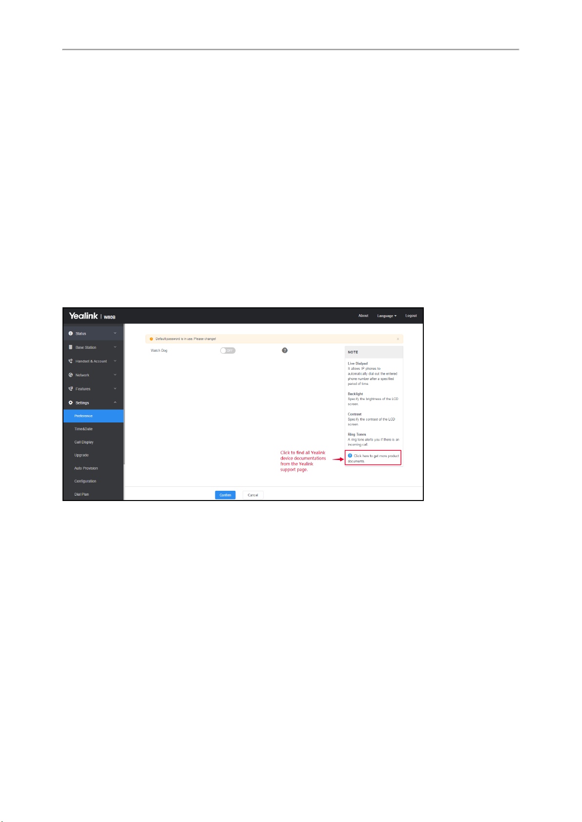
When you log into the web user interface successfully, the device status is displayed on the first page of the web user
interface.
The following figure is an example when you navigate to Settings > Preference:
Logging out of the Web User Interface
By default, the device will automatically log out of the web user interface after five minutes of inactivity. You can also
manually log out of the web user interface.
Procedure
1. Click Logout at the top right of each web page.
18

Initialization Instructions
Initialization Instructions
This chapter provides basic initialization instructions of devices.
Topics
Initialization Process Overview
Verifying Startup
Initialization Process Overview
The initialization process of the device is responsible for network connectivity and operation of the device in your local
network. Once you connect your device to the network and to an electrical supply, the device begins its initialization
process.
Topics
Loading the ROM File
Configuring the VLAN
Querying the DHCP (Dynamic Host Configuration Protocol) Server
Contacting the Provisioning Server
Updating Firmware
Downloading the Resource Files
Loading the ROM File
The ROM file resides in the flash memory of the device. The device comes from the factory with a ROM file preloaded.
During initialization, the device runs a bootstrap loader that loads and executes the ROM file.
Configuring the VLAN
If you connect the device to a switch, the switch notifies the device of the VLAN information defined on the switch (if
using LLDP or CDP). The device can then proceed with the DHCP request for its network settings (if using DHCP).
Querying the DHCP (Dynamic Host Configuration Protocol) Server
The device is capable of querying a DHCP server.
After establishing network connectivity, the device can obtain the following network parameters from the DHCP server
during initialization:
l IP Address
l Subnet Mask
l Default Gateway
l Primary DNS (Domain Name Server)
l Secondary DNS
By default, the devices obtain these parameters from a DHCPv4. You can configure network parameters of the device
manually if any of them are not supplied by the DHCP server.
Contacting the Provisioning Server
If you configure the device to obtain configurations from the provisioning server, it will be connected to the provisioning server, and then download the boot file and configuration file(s) during startup. The device will be able to
resolve and update configurations written in the configuration file(s). If the device does not obtain configurations from
the provisioning server, it will use the configurations stored in the flash memory.
19

Administrator’s Guide for DECT Multi-Cell System
Updating Firmware
If you define the access URL of firmware in the configuration file, the device will download the firmware from the provisioning server. If the MD5 value of the downloaded firmware file differs from that stored in the flash memory, the
device will perform a firmware update.
You can manually upgrade the firmware if the device does not download the firmware from the provisioning server.
Downloading the Resource Files
In addition to the configuration file(s), the device may require resource files before it provides service. These resource
files are optional, but if you deploy some particular features, these files are required.
Verifying Startup
After connected to the power and available network, the LAN LED indicator glows green. In the DM-Base mode, the
ROLE LED indicator glows orange and the DECT LED indicator glows green.
20
Setting up the Base Stations
Setting up the Base Stations
When the W80B device role is Base, the device must be registered to the DM for normal use.
In the multicast network, the DM automatically recognizes the base stations within the network. In the non-multicast
network, the DM recognizes the base stations only when the IP address of DM is configured to the base stations via the
web user interface or RPS.
After recognized, the base stations need to be registered, activated, and synchronized.
Topics
Base Mode
Base Station Pre-registration
DM IP
Base Station Settings
Base Station Synchronization
Base Mode
You can assign a role for the device via the web user interface or auto provisioning.
Topics
Base Mode Configuration
LED Indicators on the W80B
Base Mode Configuration
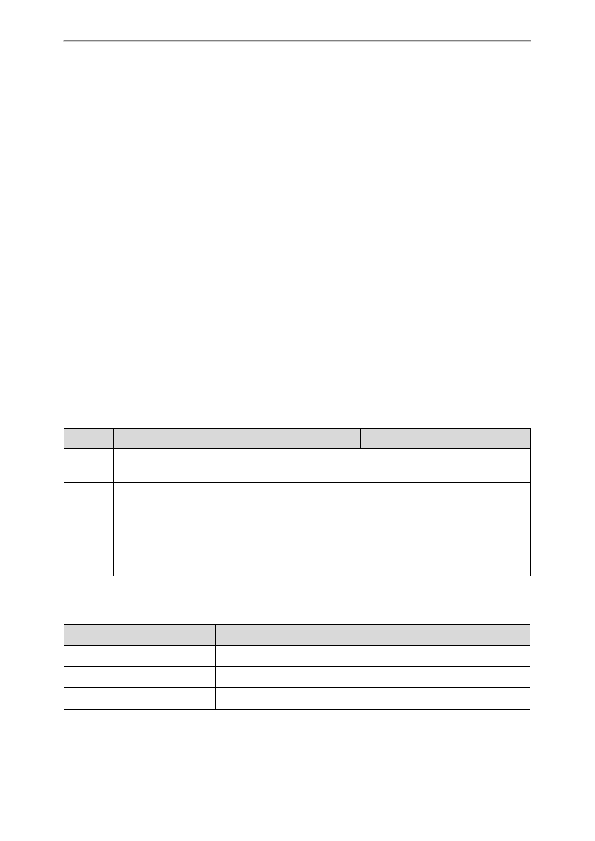
The following table lists the parameter you can use to configure the base mode.
Parameter static.station.mode <y0000000000xx>.cfg
Description It configures the role of the W80B device.
0-DM-Base, the device can work as a DECT manager and base station.
Permitted
Values
Default 1
Web UI Status > Base Mode > Base Mode
1-Base, the device works as a base station only.
2-DM, the device works as a DECT manager only.
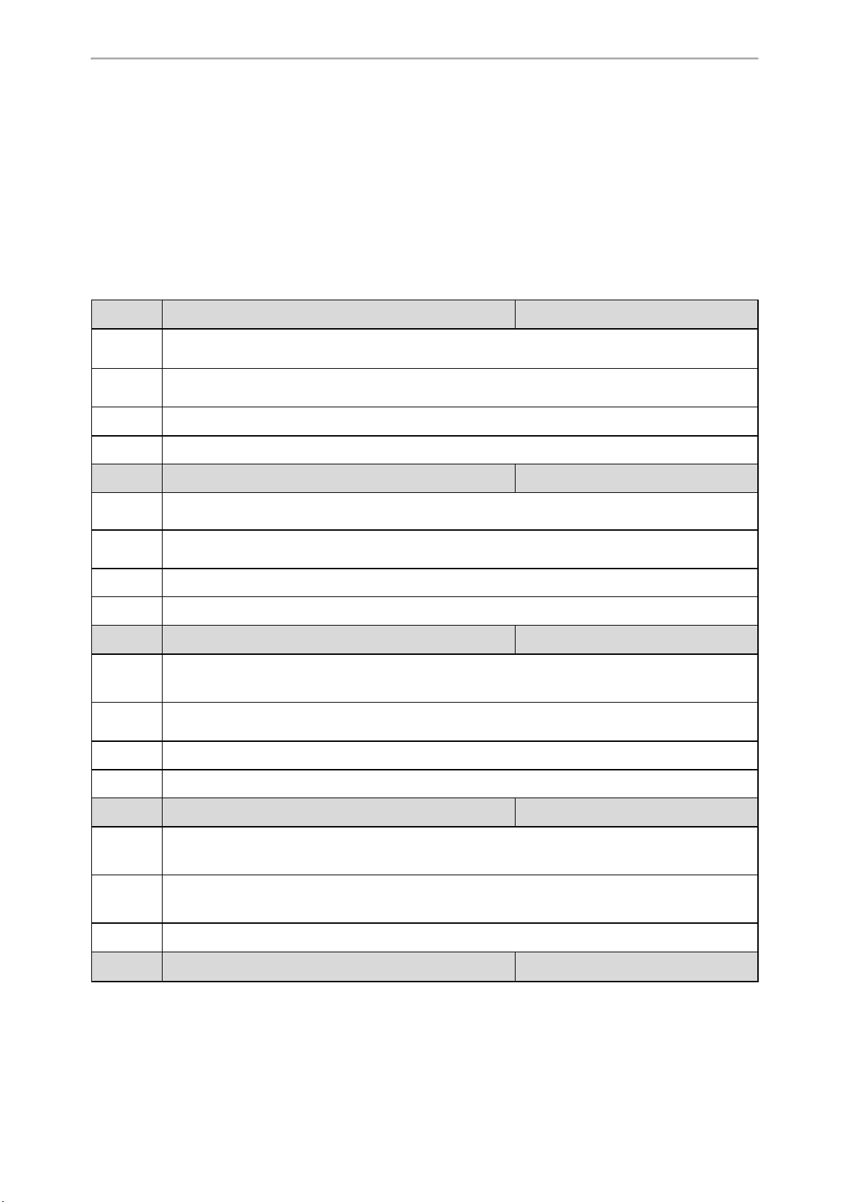
LED Indicators on the W80B
LAN LED: indicates the LAN connection status.
LAN LED Description
Green Successful connection to LAN
Slowly flashing green (1s) No connection to LAN or no IP address available/ assigned
Off Power off
ROLE LED: indicates the device role.
21
Administrator’s Guide for DECT Multi-Cell System
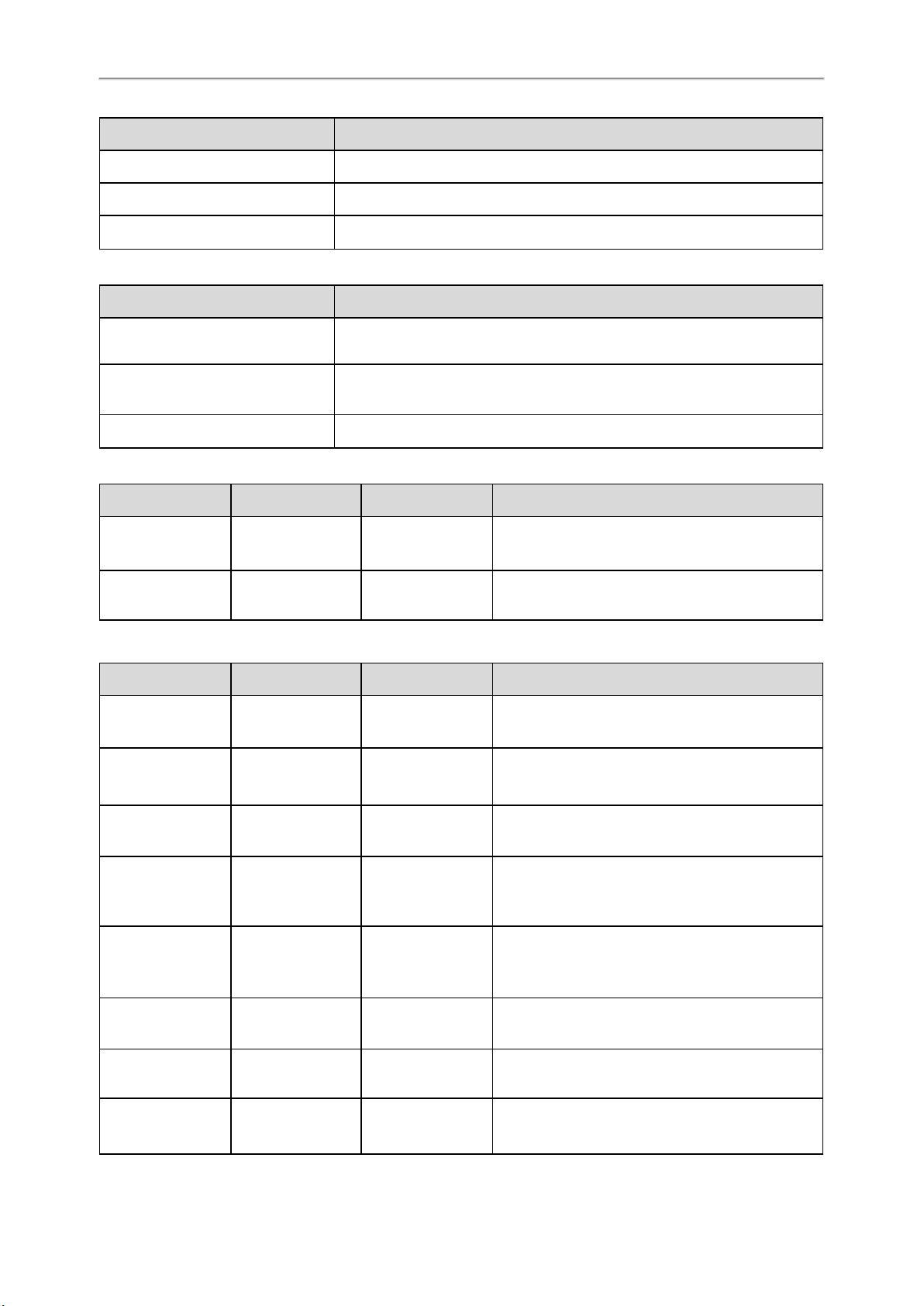
ROLE LED Description
Orange Device role: DM or DM-Base.
Green Device role: Base.
Slowly flashing orange (1s) Active calls in the system
DECT LED: indicates the connection status to the DM.
DECT LED Description
Green Successful connection to DM, status: Active and synced
Off Successful connection to DM, status: Active, Deactive, or Offline
Slowly flashing green (1s) Active calls on the base station
You can register handsets while the device role is DM-Base. The LED indicators are shown below:
LAN LED ROLE LED DECT LED Description
Green Orange
Green Orange Green Handset registered
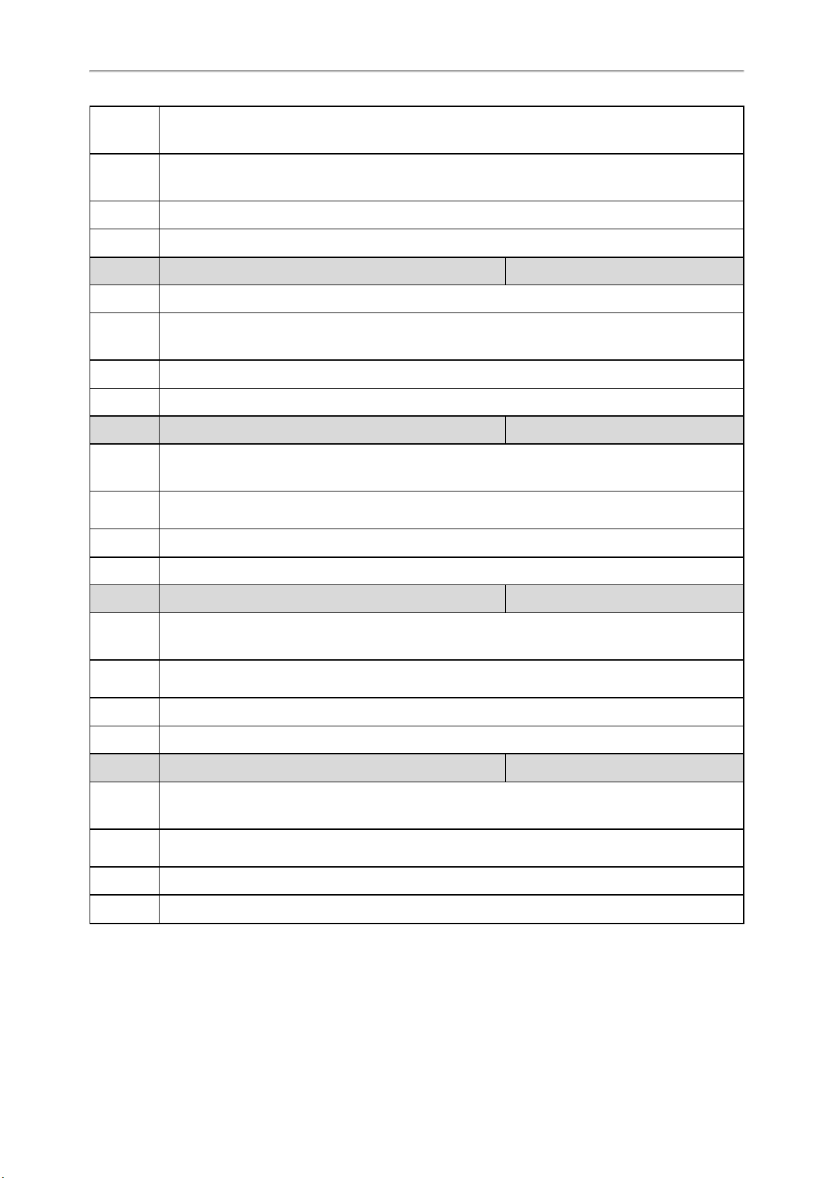
LED indicators (some common status)
LAN LED ROLE LED DECT LED Description
Slowly flashing
green (1s)
Slowly flashing
green (1s)
Green Green Green Synchronized, status: Active and synced
Green Green Off
Green Green
Green Off Device role: Base, no connection to LAN
Orange Off Device role: DM or DM-Base, no connection to LAN
Slowly flashing
green(1s)
Slowly flashing
green(1s)
Handset registering
Not synchronized, status: Active, Deactive, or Off-
line
Successful connection to DM, active calls on the base
station
Green Orange Green First-level base station connected
Green Orange Off No connected base on the DM
Green
22
Slowly flashing Slowly flashing
Device role: DM-Base, active calls on the device
Setting up the Base Stations
LAN LED ROLE LED DECT LED Description
orange (1s) green (1s)
Green
Fast flashing green
(0.5s)
Green Orange Orange Device role: DM-Base, test mode
Slowly flashing
orange (1s)
Fast flashing green
(0.5s)
Green Active calls in the system
Fast flashing green
(0.5s)
Firmware update in progress
Base Station Pre-registration
In the multicast network, you can pre-register all base stations at the DM. After that, the base stations will be automatically registered at the DM once being detected in the network.
If the detected base station has not been pre-registered at the DM, you need to manually register the base stations via
the web user interface.
Topics
Base Station Pre-registration Configuration
Manually Registering Base Stations to the DM
Base Station Pre-registration Configuration
The following table lists the parameters you can use to pre-register the base station.
Parameter station.allowed.X.mac
Description It sets the MAC address of the pre-registration base station.
Permitted
Values
Default Blank
Parameter station.allowed.X.name
Description It sets the name of the pre-registration base station.
Permitted
Values
Default Blank
Parameter station.allowed.X.sync.cluster
Description It sets the sync cluster of the pre-registration base station.
Permitted
Values
String within 32 characters
String within 32 characters
Integer from 1 to 10
[1]
[1]
[1]
<y0000000000xx>.cfg
<y0000000000xx>.cfg
<y0000000000xx>.cfg
23
Administrator’s Guide for DECT Multi-Cell System
Default Blank
Parameter station.allowed.X.sync.level
Description It sets the sync level of the pre-registration base station.
[1]
<y0000000000xx>.cfg
Permitted
Values
Default Blank
[1]
X is the pre-registration ID. X=1-30.
Integer from 1 to 10
Manually Registering Base Stations to the DM
You are allowed to manually register the base stations to the DM in the base station standby list.
Procedure
1. Access the web user interface of the device.
2. Navigate to Base Station > Base Station Registration.
3. Click next to the base station.
4. Complete the corresponding information of the base station, and click OK.
The base station is successfully registered to the DM.
Related Topic
Accessing Web User Interface
DM IP
In the non-multicast network, the DM can detect and connect the base station only when you have configured the IP
address of the DM on the base station.
Note: You can configure the IP address of the DM for all base stations using RPS. Otherwise, you need to switch the W80B
device to the DM-Base role first and then register a handset to the device to find the device's IP address. After accessing
the web user interface, switch the W80B to the Base role and configure the IP address of the DM.
Topic
DM IP Configuration
DM IP Configuration
The following table lists the parameter you can use to configure the DM IP.
Parameter features.dect_management.ip_address <y0000000000xx>.cfg
Description
Permitted
Values
Default Blank
Web UI Status > Base Mode > DM IP
It configures the IP address of the DM.
Note: It works only if "static.station.mode" is set to 1 (Base).
String within 64 characters
24
Base Station Settings
You can modify all settings of the registered base stations at the DECT manager.
Topics
Base Station Settings Configuration
Managing the Connected Base Stations
Base Station Settings Configuration
The following table lists the parameters you can use to modify the base station settings.
Setting up the Base Stations
Parameter station.X.name
Description It sets the name of the base station.
Permitted
Values
Default Base station X
Web UI Base Station > Base Station Settings > Edit > Name / Location
Parameter station.X.sync.cluster
Description It sets the sync cluster to which the base station belongs.
Permitted
Values
Default 1
Web UI Base Station > Base Station Settings > Edit > Cluster
Parameter station.X.sync.level
Description It sets the sync level of the base station.
Permitted
Values
String within 32 characters
Integer from 1 to 10
Integer from 1 to 10
[1]
[1]
[1]
<y0000000000xx>.cfg
<y0000000000xx>.cfg
<y0000000000xx>.cfg
Default 1
Web UI Base Station > Base Station Settings > Edit > Sync Level
Parameter station.X.sync.type
Description It sets the sync type of the base station.
Permitted
Values
Default 2
Parameter station.X.active
0-Disabled
2-Over the air synchronization
[1]
[1]
<y0000000000xx>.cfg
<y0000000000xx>.cfg
25
Administrator’s Guide for DECT Multi-Cell System
Description It triggers the active base station feature to on or off.
Permitted
Values
0-OFF
1-ON
Default 1
Web UI Base Station > Base Station Settings > Edit > Active Base Station
Parameter
static.station.X.network.type
[1]
Description It configures the type of network.
Permitted
Values
0-DHCP
2-Static IP
Default 0
Web UI Base Station > Base Station Settings > Edit > IP Address Type
Parameter
static.station.X.network.ip
[1]
It configures the IPv4 address.
Description
Note: It works only if "static.station.X.network.type" is set to 2 (Static IP).
Permitted
Values
String within 64 characters
Default Blank
<y0000000000xx>.cfg
<y0000000000xx>.cfg
Web UI Base Station > Base Station Settings > Edit > IP Address
Parameter
static.station.X.network.mask
[1]
It configures the IPv4 subnet mask.
Description
Note: It works only if "static.station.X.network.type" is set to 2 (Static IP).
Permitted
Values
String within 64 characters
Default Blank
Web UI Base Station > Base Station Settings > Edit > Subnet Mask
Parameter
static.station.X.network.gateway
[1]
It configures the IPv4 default gateway.
Description
Note: It works only if "static.station.X.network.type" is set to 2 (Static IP).
Permitted
Values
String within 64 characters
Default Blank
Web UI Base Station > Base Station Settings > Edit > Default Gateway
[1]
X is the registration location ID. X=1-30.
<y0000000000xx>.cfg
<y0000000000xx>.cfg
Managing the Connected Base Stations
You can edit the data for a base station or manage a base station that is already registered to the DM.
26
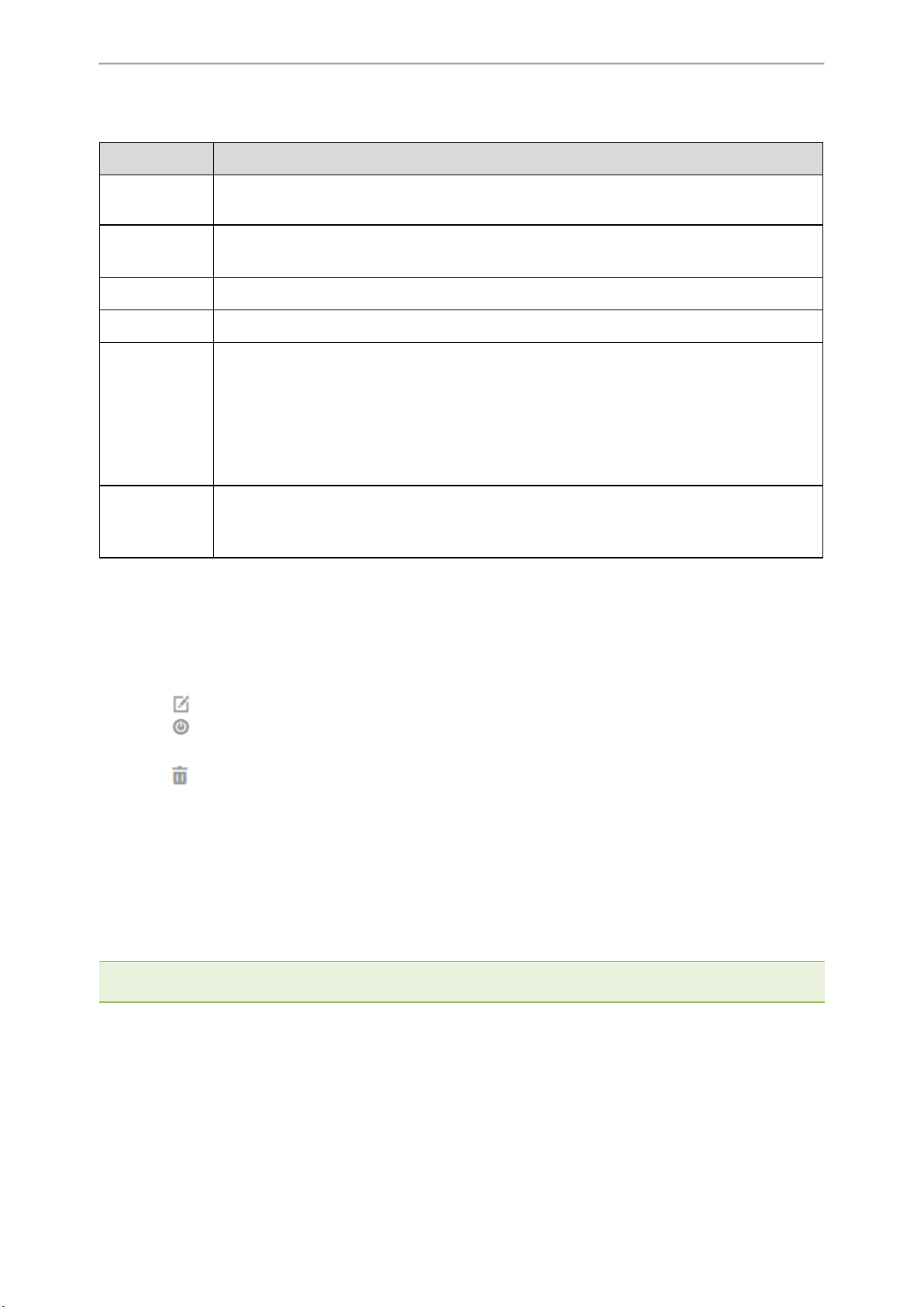
You can customize the following information of the connected base stations:
Item Description
Setting up the Base Stations
Base Station
Name of the base station. When added to the list, Base Station X (X ranges from 1to 30) is used as
the name.
Radio Fixed Part Number. The base station identity allocated by the DECT system.
RPN
Note: This cannot be edited.
Cluster Number of the cluster to which the base station belongs.
Sync Level Sync level within the sync hierarchy.
Synchronization status of the base station.
• Offline: not available.
Status
• Deactive: available but not activated.
• Active: activated but not synchronized.
• Active and synced: activated and synchronized.
Activates or deactivates the base station.
Active
Note: A base station must be active to manage calls of the connected handsets. If it is deactivated,
it will no longer connect handsets but it still stays in the list of connected base stations.
Procedure
1. You can do the following:
l Select ON or OFF to activate or deactivate the base station.
Note: Please ensure that the base station you want to deactivate is not with sync level 1. Check your sync settings
before deactivating the base station. Otherwise, your system may no longer work properly.
l Click , and enter a descriptive name, assign the cluster, and set the sync level for the base station.
l Click and select OK to reboot the base station.
All existing connections managed by the base station are terminated.
l Click and select OK to delete the base station.
l Click Reboot All to reboot all connected base stations.
Base Station Synchronization
Base station synchronization is the prerequisite for the functioning of the multi-cell system, inter-cell handover, and
overload balancing. Overload balancing means that a handset can roam to another available base when the current
base is fully loaded and cannot accept further handset connections.
Base stations can be synchronized "over the air", meaning that they are synchronized via DECT.
Note: Synchronization always refers to a cluster. In case you set up several clusters that are not synchronized with one
another, these will be no possibility of a handover or overload balancing between them.
Topic
Synchronization Planning
27
 Loading...