


Copyright
Copyright © 2017 YEALINK(XIAMEN) NETWORK TECHNOLOGY
Copyright © 2017 Yealink (Xiamen) Network Technology CO., LTD. All rights reserved. No parts of this
publication may be reproduced or transmitted in any form or by any means, electronic or mechanical,
photocopying, recording, or otherwise, for any purpose, without the express written permission of
Yealink (Xiamen) Network Technology CO., LTD. Under the law, reproducing includes translating into
another language or format.
When this publication is made available on media, Yealink (Xiamen) Network Technology CO., LTD. gives
its consent to downloading and printing copies of the content provided in this file only for private use
but not for redistribution. No parts of this publication may be subject to alteration, modification or
commercial use. Yealink (Xiamen) Network Technology CO., LTD. will not be liable for any damages
arising from use of an illegally modified or altered publication.
Trademarks
Yealink®, the logo and the name and marks is trademark of Yealink (Xiamen) Network Technology CO.,
LTD, which are registered legally in China, the United States, EU (European Union) and other countries.
All other trademarks belong to their respective owners. Without Yealink’s express written permission,
recipient shall not reproduce or transmit any portion hereof in any form or by any means, with any
purpose other than personal use.
Warranty
(1) Warranty
THE SPECIFICATIONS AND INFORMATION REGARDING THE PRODUCTS IN THIS GUIDE ARE SUBJECT TO
CHANGE WITHOUT NOTICE. ALL STATEMENTS, INFORMATION, AND RECOMMENDATIONS IN THIS
GUIDE ARE BELIEVED TO BE ACCURATE AND PRESENTED WITHOUT WARRANTY OF ANY KIND, EXPRESS
OR IMPLIED. USERS MUST TAKE FULL RESPONSIBILITY FOR THEIR APPLICATION OF PRODUCTS.
(2) Disclaimer
YEALINK (XIAMEN) NETWORK TECHNOLOGY CO., LTD. MAKES NO WARRANTY OF ANY KIND WITH
REGARD TO THIS GUIDE, INCLUDING, BUT NOT LIMITED TO, THE IMPLIED WARRANTIES OF
MERCHANTABILITY AND FITNESS FOR A PARTICULAR PURPOSE. Yealink (Xiamen) Network Technology
CO., LTD. shall not be liable for errors contained herein nor for incidental or consequential damages in
connection with the furnishing, performance, or use of this guide.
(3) Limitation of Liability
Yealink and/or its respective suppliers are not responsible for the suitability of the information contained
in this document for any reason. The information is provided “as is”, and Yealink does not provide any
warranty and is subject to change without notice. All risks other than risks caused by use of the
information are borne by the recipient. In no event, even if Yealink has been suggested the occurrence of
ii

damages that are direct, consequential, incidental, special, punitive or whatsoever (Including but not
limited to loss of business profit, business interruption or loss of business information), shall not be liable
for these damages.
End User License Agreement
This End User License Agreement ("EULA") is a legal agreement between you and Yealink. By installing,
copying or otherwise using the Products, you: (1) agree to be bounded by the terms of this EULA, (2) you
are the owner or an authorized user of the device, and (3) you represent and warrant that you have the
right, authority and capacity to enter into this agreement and to abide by all its terms and conditions, just
as if you had signed it. The EULA for this product is available on the Yealink Support page for the product.
Patent Information
China, the United States, EU (European Union) and other countries are protecting one or more patents of
accompanying products and/or patents being applied by Yealink.
Customer Feedback
We are striving to improve our documentation quality and we appreciate your feedback. Email your
opinions and comments to DocsFeedback@yealink.com.
Technical Support
Visit Yealink WIKI (http://support.yealink.com/) for the latest firmware, guides, FAQ, Product documents,
and more. For better service, we sincerely recommend you to use Yealink Ticketing system
(https://ticket.yealink.com) to submit all your technical issues.

GNU GPL INFORMATION
Yealink IP phone firmware contains third-party software under the GNU General Public License (GPL). Yealink uses
software under the specific terms of the GPL. Please refer to the GPL for the exact terms and conditions of the license.
The original GPL license, source code of components licensed under GPL and used in Yealink products can be
downloaded from Yealink web site:
http://www.yealink.com/GPLOpenSource.aspx?BaseInfoCateId=293&NewsCateId=293&CateId=293.
iv

Introduction
About This Guide
Yealink administrator guide is intended for administrators who need to properly configure,
customize, manage, and troubleshoot the smart media phones rather than end-users. This guide
will help you understand the VoIP network and SIP components, and provides descriptions of all
available phone features.
This guide describes three methods for configuring IP phones: central provisioning, web user
interface and phone user interface. It will help you perform the following tasks:
Configure your IP phone on a provisioning server
Configure your phone’s features and functions via web/phone user interface
Introduction
Troubleshoot some common phone issues
Many of the features described in this guide involve network settings, which could affect the IP
phone’s performance in the network. So an understanding of IP networking and a prior
knowledge of IP telephony concepts are necessary.
The information detailed in this guide is applicable to firmware version 80 or higher. The
firmware format is like x.x.x.x.rom. The second x from left must be greater than or equal to 80
(e.g., the firmware version of SIP-T58V IP phone: 58.80.0.5.rom).
Chapters in This Guide
This administrator guide includes the following chapters:
Chapter 1, “Product Overview” describes the smart media phones and expansion modules.
Chapter 2, “Getting Started” describes how Yealink phones fit in your network and how to
install and connect IP phones, and also gives you an overview of IP phone’s initialization
process.
Chapter 3, “Setting Up Your System” describes some essential information on how to set
up your phone network and set up your phone with a provisioning server.
Chapter 4, “Configuring Basic Features” describes how to configure the basic features on IP
phones.
Chapter 5, “Configuring Advanced Features” describes how to configure the advanced
features on IP phones.
Chapter 6, “Configuring Audio Features” describes how to configure the audio features on
IP phones.
Chapter 7, “Configuring Video Features” describes how to configure the video features on
v

Administrator’s Guide for SIP-T5 Series Smart Media Phones
IP phones.
Chapter 8, “Configuring Security Features” describes how to configure the security features
on IP phones.
Chapter 9, “Troubleshooting” describes how to troubleshoot IP phones and provides some
common troubleshooting solutions.
Chapter 10, “Appendix” provides the glossary, time zones, trusted certificates, auto
provisioning flowchart, reference information about IP phones compliant with RFC 3261,
SIP call flows, some other function lists (e.g., DSS keys, reading icons) and index.
Related Documentations
The following related documents for SIP-T58V/A, SIP-T56A and CP960 IP phones are available:
Quick Start Guides, which describe how to assemble IP phones and configure the most
basic features available on IP phones.
User Guides, which describe how to configure and use the basic and advanced features
available on IP phones via phone user interface.
Auto Provisioning Guide, which describes how to provision IP phones using the
configuration files.
The purpose of
Auto Provisioning Guide
is to serve as a basic guidance for provisioning
Yealink IP phones with a provisioning server. If you are new to this process, it is helpful to
read this guide.
Description of Configuration Parameters in CFG Files, which describes all configuration
parameters in configuration files.
Note that Yealink administrator guide contains most of parameters. If you want to find out
more parameters not listed in this guide, please refer to
Parameters in CFG Files
y000000000000.boot template boot file.
<y0000000000xx>.cfg and <MAC>.cfg template configuration files.
IP Phones Deployment Guide for BroadSoft UC-One Environments, which describes how to
guide.
Description of Configuration
configure BroadSoft features on the BroadWorks web portal and IP phones.
IP Phone Features Integrated with BroadSoft UC-One User Guide, which describes how to
configure and use IP phone features integrated with BroadSoft UC-One on Yealink IP
phones.
vi
When the SIP server type is set to BroadSoft, please refer to these two guides to have a
better knowledge of configuring and using features integrated with Broadsoft UC-One.
For support or service, please contact your Yealink reseller or go to Yealink Technical Support
online: http://support.yealink.com/.

Conventions Used in Yealink Documentations
Convention
Description
Bold
Highlights the web/phone user interface items such as menus, menu
selections, soft keys, or directory names when they are involved in a
procedure or user action (e.g., Click on Settings->Upgrade.).
Also used to emphasize text (e.g., Important!).
Italics
Used to show the format of examples (e.g.,
http(s)://[IPv6 address]
),
or to show the title of a section in the reference documentations
available on the Yealink Technical Support Website (e.g.,
Triggering
the IP phone to Perform the Auto Provisioning
).
Blue Text
Used for cross references to other sections within this
documentation (e.g., refer to Ring Tones on page 601), for
hyperlinks to non-Yealink websites (e.g., RFC 3315) or for hyperlinks
to Yealink Technical Support website.
Blue Text in Italics
Used for hyperlinks to Yealink resources outside of this
documentation such as the Yealink documentations (e.g.,
Yealink_SIP-T2_Series_T19(P)
E2_T4_Series_T5_Series_W5_Series_CP_Series_IP_Phones_Auto_Provis
ioning_Guide_V81
).
Convention
Description
<>
Indicates that you must enter information specific to phone or
network. For example, when you see <MAC>, enter your phone’s
12-digit MAC address. If you see <phoneIPAddress>, enter your
phone’s IP address.
->
Indicates that you need to select an item from a menu. For
example, Settings->Basic indicates that you need to select Basic
from the Settings menu via phone user interface.
Note: By default, the Settings menu locates on the second idle
screen. You need to swipe left/right to see it. Or, you can also
swipe down from the top of the screen to enter the control center
Yealink documentations contain a few typographic conventions and writing conventions.
You need to know the following basic typographic conventions to distinguish types of in-text
information:
Introduction
You also need to know the following writing conventions to distinguish conditional information:
Reading the Configuration Parameter Tables
The feature descriptions discussed in this guide include two tables. One is a summary table of
vii

Administrator’s Guide for SIP-T5 Series Smart Media Phones
provisioning methods that you can use to configure the features. The other is a table of details
of the configuration parameters that you configure to make the features work.
This brief section describes the conventions used in the summary table and configuration
parameter table. In order to read the tables and successfully perform configuration changes, an
understanding of these conventions is necessary.
Summary Table Format
The following summary table indicates three provisioning methods (central provisioning, web
user interface and phone user interface, refer to Provisioning Methods for more information)
you can use to configure a feature. Note that the types of provisioning methods available for
each feature will vary; not every feature uses all these three methods.
The central provisioning method requires you to configure parameters located in CFG format
configuration files that Yealink provides. For more information on configuration files, refer to
Configuration Files on page 116. As shown below, the table specifies the configuration file name
and the corresponding parameters. That is, the MAC.cfg file contains the
parameter, and the y0000000000xx.cfg file contains the
account.X.auto_answer
feature.auto_answer_delay
parameter.
The web user interface method requires you to configure features by navigating to the specified
link. This navigation URL can help you quickly locate the webpage where you can configure the
feature.
viii

Configuration Parameter Table Format
Sometimes you will see the words “Refer to the following content” in the Permitted Values or
The following configuration parameter table describes the parameter that you can configure to
make the feature (e.g., auto answer) work.
Introduction
Note
Default field. It means the permitted value or the default value of the parameter has the model
difference or there are many permitted values of the parameter, you can get more details from
the following Description field.
The word “None” in the Web User Interface or Phone User Interface field means this feature
cannot be configurable via web/phone user interface.
The above table also indicates three methods for configuring the feature.
Method 1: Central Provisioning
This table specifies the details of
the auto answer feature. This parameter is disabled by default. If you want to enable the auto
answer feature, open the MAC.cfg file and locate the parameter name
Set the parameter value to “1” to enable the auto answer feature or “0” to disable the auto
answer feature.
Note that some parameters described in this guide contain one or more variables (e.g., X or Y).
But the variables in the parameters described in the CFG file are all replaced with specific value
in the scope of variable. You may need to assign a value to the variable before you search and
locate the specific parameter in the CFG file.
account.X.auto_answer
parameter, which enables or disables
account.X.auto_answer
.
For example, if you want to enable the auto answer feature for account 1, you need to locate the
account.1.auto_answer
account.1.auto_answer = 1). If you want to enable the audio codec 1 for account 1, you can
in the MAC.cfg file and then configure it as required (e.g.,
ix

Administrator’s Guide for SIP-T5 Series Smart Media Phones
locate the
account.1.codec.1.enable = 1).
The following shows a segment of MAC.cfg file:
account.1.codec.1.enable
in the MAC.cfg file and configure it as required (e.g.,
Method 2: Web User Interface
As described in the chapter Summary Table Format, you can directly navigate to the specified
webpage to configure the feature. You can also first log into the web user interface, and then
locate the feature field according to the web path (e.g., Account->Basic->Auto Answer) to
configure it as required.
As shown in the following illustration:
x

Introduction
To successfully log into the web user interface, you may need to enter the user name (default:
admin) and password (default: admin). For more information, refer to Web User Interface on
page 113.
Method 3: Phone User Interface
You can configure features via phone user interface. Access to the desired feature according to
the phone path (e.g., Settings->Features->Auto Answer->Account X) and then configure it as
required.
As shown in the following illustration:
Recommended References
For more information on configuring and administering other Yealink products not included in
this guide, refer to product support page at Yealink Technical Support.
To access the latest Release Notes or other guides for Yealink IP phones, refer to the Document
Download page for your phone at Yealink Technical Support.
If you want to find Request for Comments (RFC) documents, type
http://www.ietf.org/rfc/rfcNNNN.txt
browser.
This guide mainly takes the SIP-T58V IP phones as example for reference. For more details on
other IP phones, refer to
For other references, look for the hyperlink or web info throughout this administrator guide.
Yealink phone-specific user guide
(NNNN is the RFC number) into the location field of your
.
Understanding VoIP Principle and SIP Components
This section mainly describes the basic knowledge of VoIP principle and SIP components, which
will help you have a better understanding of the phone’s deployment scenarios.
xi

Administrator’s Guide for SIP-T5 Series Smart Media Phones
VoIP Principle
VoIP
VoIP (Voice over Internet Protocol) is a technology using the Internet Protocol instead of
traditional Public Switch Telephone Network (PSTN) technology for voice communications.
It is a family of technologies, methodologies, communication protocols, and transmission
techniques for the delivery of voice communications and multimedia sessions over IP networks.
The H.323 and Session Initiation Protocol (SIP) are two popular VoIP protocols that are found in
widespread implementation.
H.323
H.323 is a recommendation from the ITU Telecommunication Standardization Sector (ITU-T)
that defines the protocols to provide audio-visual communication sessions on any packet
network. The H.323 standard addresses call signaling and control, multimedia transport and
control, and bandwidth control for point-to-point and multi-point conferences.
It is widely implemented by voice and video conference equipment manufacturers, is used
within various Internet real-time applications such as GnuGK and NetMeeting and is widely
deployed by service providers and enterprises for both voice and video services over IP
networks.
SIP
SIP (Session Initiation Protocol) is the Internet Engineering Task Force’s (IETF’s) standard for
multimedia conferencing over IP. It is an ASCII-based, application-layer control protocol
(defined in RFC 3261) that can be used to establish, maintain, and terminate calls between two
or more endpoints. Like other VoIP protocols, SIP is designed to address functions of signaling
and session management within a packet telephony network. Signaling allows call information
to be carried across network boundaries. Session management provides the ability to control
attributes of an end-to-end call.
SIP provides capabilities to:
Determine the location of the target endpoint -- SIP supports address resolution, name
mapping, and call redirection.
Determine media capabilities of the target endpoint -- Via Session Description Protocol
(SDP), SIP determines the “lowest level” of common services between endpoints.
Conferences are established using only media capabilities that can be supported by all
endpoints.
xii
Determine the availability of the target endpoint -- A call cannot be completed because
the target endpoint is unavailable, SIP determines whether the called party is already on
the IP phone or does not answer in the allotted number of rings. It then returns a message
indicating why the target endpoint is unavailable.
Establish a session between the origin and target endpoint -- The call can be completed,

SIP establishes a session between endpoints. SIP also supports mid-call changes, such as
the addition of another endpoint to the conference or the change of a media characteristic
or codec.
Handle the transfer and termination of calls -- SIP supports the transfer of calls from one
endpoint to another. During a call transfer, SIP simply establishes a session between the
transferee and a new endpoint (specified by the transferring party) and terminates the
session between the transferee and the transferring party. At the end of a call, SIP
terminates the sessions between all parties.
SIP Components
SIP is a peer-to-peer protocol. The peers in a session are called User Agents (UAs). A user agent
can function as one of following roles:
User Agent Client (UAC) -- A client application that initiates the SIP request.
User Agent Server (UAS) -- A server application that contacts the user when a SIP request is
received and that returns a response on behalf of the user.
Introduction
User Agent Client (UAC)
The UAC is an application that initiates up to six feasible SIP requests to the UAS. The six
requests issued by the UAC are: INVITE, ACK, OPTIONS, BYE, CANCEL and REGISTER. When the
SIP session is being initiated by the UAC SIP component, the UAC determines the information
essential for the request, which is the protocol, the port and the IP address of the UAS to which
the request is being sent. This information can be dynamic and will make it challenging to put
through a firewall. For this reason, it may be recommended to open the specific application type
on the firewall. The UAC is also capable of using the information in the request URI to establish
the course of the SIP request to its destination, as the request URI always specifies the host
which is essential. The port and protocol are not always specified by the request URI. Thus if the
request does not specify a port or protocol, a default port or protocol is contacted. It may be
preferential to use this method when not using an application layer firewall. Application layer
firewalls like to know what applications are flowing through which ports and it is possible to use
content types of other applications other than the one you are trying to let through what has
been denied.
User Agent Server (UAS)
UAS is a server that hosts the application responsible for receiving the SIP requests from a UAC,
and on reception it returns a response to the request back to the UAC. The UAS may issue
multiple responses to the UAC, not necessarily a single response. Communication between UAC
and UAS is client/server and peer-to–peer.
Typically, a SIP endpoint is capable of functioning as both a UAC and a UAS, but it functions only
as one or the other per transaction. Whether the endpoint functions as a UAC or a UAS depends
on the UA that initiates the request.
xiii

Administrator’s Guide for SIP-T5 Series Smart Media Phones
Summary of Changes
This section describes the changes to this guide for each release and guide version.
Changes for Release 80, Guide Version 80.12
Documentations of the newly released CP960 IP phones have been added.
The following sections are new for this version:
CSTA Control on page 450
Real-Time Transport Protocol (RTP) Ports on page 592
Transient Noise Suppressor (TNS) on page 651
Noise Barrier Suppressor (NBS) on page 652
Major updates have occurred to the following sections:
Physical Features of IP Phones on page 2
Key Features of IP Phones on page 4
Connecting the IP Phones on page 10
Power Saving on page 157
Bluetooth on page 164
Intercom on page 412
Customizing a Local Contact File on page 270
Auto Answer on page 292
Appendix C: Trusted Certificates on page 770
Changes for Release 80, Guide Version 80.11
Major update had occurred to the following section:
Door Phone on page 441
xiv

Table of Contents
Table of Contents
Introduction.......................................................................... v
About This Guide ................................................................................................................................................... v
Chapters in This Guide ......................................................................................................................................... v
Related Documentations ................................................................................................................................... vi
Conventions Used in Yealink Documentations .......................................................................................vii
Reading the Configuration Parameter Tables ..........................................................................................vii
Summary Table Format .......................................................................................................................... viii
Configuration Parameter Table Format .............................................................................................. ix
Recommended References ............................................................................................................................... xi
Understanding VoIP Principle and SIP Components ............................................................................. xi
VoIP Principle ............................................................................................................................................... xii
SIP Components ........................................................................................................................................ xiii
Summary of Changes ....................................................................................................................................... xiv
Changes for Release 80, Guide Version 80.12 .............................................................................. xiv
Changes for Release 80, Guide Version 80.11 .............................................................................. xiv
Table of Contents ............................................................... xv
Product Overview ................................................................ 1
SIP IP Phone Models .............................................................................................................................................1
Physical Features of IP Phones ................................................................................................................2
Key Features of IP Phones .........................................................................................................................4
Expansion Modules ...............................................................................................................................................6
Getting Started ..................................................................... 9
What IP Phones Need to Meet .........................................................................................................................9
Yealink IP Phones in a Network .......................................................................................................................9
Connecting the IP Phones ............................................................................................................................... 10
Inserting the Camera (only applicable to SIP-T58V/A IP phones) ........................................ 11
Attaching the Stand and the Optional Wall Mount Bracket (not applicable to CP960 IP phones)
........................................................................................................................................................................... 12
Adjust the angle of touch screen (only applicable to SIP-T58V/A IP phones)................. 14
Connecting the Handset and Optional Headset (not applicable to CP960 IP phones)14
Connecting the Power and Network ................................................................................................. 15
Connecting the Optional USB Flash Drive....................................................................................... 18
Connecting the Wired Expansion MIC CPE90 (Only Applicable to CP960 IP Phones) . 19
xv

Administrator’s Guide for SIP-T5 Series Smart Media Phones
Connecting the Optional PC using a Micro USB Cable (Only Applicable to CP960 IP Phones) 19
Connecting the Optional External Speaker (Only Applicable to CP960 IP Phones) ...... 20
Initialization Process Overview ...................................................................................................................... 20
Verifying Startup ................................................................................................................................................. 21
Setting Up Your System .................................................... 23
Setting Up Your Phone Network .................................................................................................................. 23
DHCP ............................................................................................................................................................... 24
DHCP Option ............................................................................................................................................... 28
Configuring Network Parameters Manually ................................................................................... 32
PPPoE .............................................................................................................................................................. 38
Configuring Transmission Methods of the Internet Port and PC Port ................................ 40
Configuring PC Port Mode .................................................................................................................... 44
Web Server Type ........................................................................................................................................ 46
Wi-Fi ................................................................................................................................................................ 50
VLAN ............................................................................................................................................................... 53
IPv6 Support ................................................................................................................................................ 66
VPN .................................................................................................................................................................. 76
Configuring the IP Phone for Use with a Firewall or NAT ........................................................ 80
Quality of Service (QoS) .......................................................................................................................... 95
802.1X Authentication ............................................................................................................................. 99
Setting Up Your Phones with a Provisioning Server ......................................................................... 110
Provisioning Points to Consider ....................................................................................................... 110
Provisioning Methods ........................................................................................................................... 111
Boot Files, Configuration Files and Resource Files ................................................................... 114
Setting Up a Provisioning Server ..................................................................................................... 121
Upgrading Firmware .............................................................................................................................. 124
Keeping User Personalized Settings after Auto Provisioning .............................................. 132
Configuring Basic Features ............................................ 143
Power Indicator LED ........................................................................................................................................ 145
Notification Popups ........................................................................................................................................ 149
Wallpaper ............................................................................................................................................................ 152
Screen Saver ....................................................................................................................................................... 156
Power Saving ..................................................................................................................................................... 157
Backlight .............................................................................................................................................................. 162
Bluetooth ............................................................................................................................................................. 164
Enable Page Tips .............................................................................................................................................. 169
Page Tips for Expansion Module ............................................................................................................... 171
Account Registration ...................................................................................................................................... 172
Multiple Line Keys per Account ................................................................................................................. 180
Call Display ......................................................................................................................................................... 184
Display Method on Dialing .......................................................................................................................... 186
xvi

Table of Contents
Time and Date ................................................................................................................................................... 188
NTP Time Server ...................................................................................................................................... 189
Time and Date Settings ........................................................................................................................ 194
Daylight Saving Time (DST) ................................................................................................................ 197
Language ............................................................................................................................................................. 205
Loading Language Packs ..................................................................................................................... 206
Specifying the Language to Use....................................................................................................... 213
Softkey Layout ................................................................................................................................................... 215
Customizing Softkey Layout Template File .................................................................................. 217
Key As Send ........................................................................................................................................................ 223
Dial Plan ............................................................................................................................................................... 227
Dial Plan using XML Template Files ................................................................................................ 227
Dial Plan using Digit Map String Rules .......................................................................................... 242
Emergency Dialplan ........................................................................................................................................ 251
Hotline .................................................................................................................................................................. 255
Off Hook Hot Line Dialing ............................................................................................................................ 258
Search Source List In Dialing ....................................................................................................................... 260
Customizing a Super Search Template File ................................................................................. 260
Save Call Log ...................................................................................................................................................... 263
Call List Show Number ................................................................................................................................... 265
Missed Call Log ................................................................................................................................................. 266
Local Directory .................................................................................................................................................. 268
Customizing a Local Contact File ..................................................................................................... 268
Configuring Local Directory ............................................................................................................... 275
Live Dialpad ........................................................................................................................................................ 280
Speed Dial ........................................................................................................................................................... 282
Call Waiting ........................................................................................................................................................ 287
Auto Redial ......................................................................................................................................................... 290
Auto Answer ....................................................................................................................................................... 292
IP Direct Auto Answer .................................................................................................................................... 297
Allow IP Call ........................................................................................................................................................ 299
Accept SIP Trust Server Only ....................................................................................................................... 300
Call Completion ................................................................................................................................................ 302
Anonymous Call ................................................................................................................................................ 305
Anonymous Call Rejection ........................................................................................................................... 309
Do Not Disturb (DND) .................................................................................................................................... 313
Busy Tone Delay ............................................................................................................................................... 325
Return Code When Refuse ........................................................................................................................... 327
Early Media ......................................................................................................................................................... 329
180 Ring Workaround .................................................................................................................................... 329
Use Outbound Proxy in Dialog .................................................................................................................. 330
SIP Session Timer ............................................................................................................................................. 332
Session Timer ..................................................................................................................................................... 334
Call Hold .............................................................................................................................................................. 337
xvii

Administrator’s Guide for SIP-T5 Series Smart Media Phones
Music on Hold (MoH) ........................................................................................................................... 341
Call Forward ........................................................................................................................................................ 343
Call Transfer ........................................................................................................................................................ 363
Local Conference .............................................................................................................................................. 366
Network Conference ....................................................................................................................................... 367
Transfer on Conference Hang Up ............................................................................................................. 369
Feature Key Synchronization ....................................................................................................................... 371
Transfer Mode via Dsskey............................................................................................................................. 372
Directed Call Pickup ........................................................................................................................................ 374
Group Call Pickup ............................................................................................................................................ 382
Dialog Info Call Pickup ................................................................................................................................... 389
Recent Call In Dialing ..................................................................................................................................... 392
ReCall .................................................................................................................................................................... 394
Call Number Filter ............................................................................................................................................ 397
Call Park ............................................................................................................................................................... 399
Calling Line Identification Presentation (CLIP) ..................................................................................... 403
Connected Line Identification Presentation (COLP) .......................................................................... 407
Mute ...................................................................................................................................................................... 410
Allow Mute ................................................................................................................................................ 410
Keep Mute ................................................................................................................................................. 411
Intercom ............................................................................................................................................................... 412
Outgoing Intercom Calls ..................................................................................................................... 413
Incoming Intercom Calls ...................................................................................................................... 419
Call Timeout ....................................................................................................................................................... 422
Ringing Timeout ............................................................................................................................................... 422
Send user=phone ............................................................................................................................................ 423
SIP Send MAC .................................................................................................................................................... 425
SIP Send Line...................................................................................................................................................... 427
Reserve # in User Name ................................................................................................................................ 429
Password Dial..................................................................................................................................................... 431
Unregister When Reboot .............................................................................................................................. 433
100 Reliable Retransmission ........................................................................................................................ 434
Reboot in Talking ............................................................................................................................................. 436
Answer By Hand ............................................................................................................................................... 438
Call Recording Using Soft Key .................................................................................................................... 439
Silent Mode ........................................................................................................................................................ 440
Door Phone ........................................................................................................................................................ 441
Mobile Account ................................................................................................................................................. 445
Quick Login ......................................................................................................................................................... 449
CSTA Control ...................................................................................................................................................... 450
Configuring Advanced Features .................................... 453
Remote Phone Book ....................................................................................................................................... 453
Customizing Remote Phone Book Template File ...................................................................... 453
xviii

Table of Contents
Lightweight Directory Access Protocol (LDAP) .................................................................................... 461
Busy Lamp Field (BLF) ..................................................................................................................................... 473
BLF Subscription ...................................................................................................................................... 473
Visual Alert and Audio Alert for BLF Pickup ................................................................................ 477
BLF LED Mode .......................................................................................................................................... 479
Configuring a BLF Key........................................................................................................................... 482
Busy Lamp Field (BLF) List ............................................................................................................................ 486
Hide Feature Access Codes .......................................................................................................................... 492
Shared Call Appearance (SCA) .................................................................................................................... 494
Message Waiting Indicator (MWI) ............................................................................................................ 503
Multicast Paging ............................................................................................................................................... 508
Sending RTP Stream .............................................................................................................................. 508
Receiving RTP Stream ........................................................................................................................... 519
Call Recording Using DSS Keys (Record and URL Record) ............................................................. 524
Hot Desking ........................................................................................................................................................ 531
Logon Wizard .................................................................................................................................................... 536
Action URL .......................................................................................................................................................... 540
Action URI ........................................................................................................................................................... 560
Configuring Trusted IP Address for Action URI ......................................................................... 564
Scenario A - Capturing the Current Screen of the Phone ..................................................... 566
Scenario B - Placing a Call via Web User Interface ................................................................... 568
Server Redundancy.......................................................................................................................................... 569
Server Domain Name Resolution ..................................................................................................... 581
Static DNS Cache.............................................................................................................................................. 584
Real-Time Transport Protocol (RTP) Ports ............................................................................................. 592
TR-069 Device Management ....................................................................................................................... 594
Configuring Audio Features ........................................... 601
Redial Tone ......................................................................................................................................................... 601
Ring Tones .......................................................................................................................................................... 602
Distinctive Ring Tones .................................................................................................................................... 607
Tones ..................................................................................................................................................................... 614
Voice Mail Tone ................................................................................................................................................ 621
Ringer Device for Headset ........................................................................................................................... 622
Headset Prior ..................................................................................................................................................... 624
Dual Headset ...................................................................................................................................................... 626
Sending Volume ............................................................................................................................................... 627
Audio Codecs ..................................................................................................................................................... 629
Supported Audio Codecs .................................................................................................................... 630
Packetization Time (PTime) ................................................................................................................ 638
Opus Sample Rate .................................................................................................................................. 640
Acoustic Clarity Technology ........................................................................................................................ 642
Acoustic Echo Cancellation (AEC) .................................................................................................... 642
Background Noise Suppression (BNS) ........................................................................................... 643
xix

Administrator’s Guide for SIP-T5 Series Smart Media Phones
Automatic Gain Control (AGC) .......................................................................................................... 644
Voice Activity Detection (VAD) ......................................................................................................... 644
Comfort Noise Generation (CNG) .................................................................................................... 645
Jitter Buffer ................................................................................................................................................ 647
Transient Noise Suppressor (TNS) ................................................................................................... 651
Noise Barrier Suppressor (NBS) ........................................................................................................ 652
DTMF ..................................................................................................................................................................... 654
Methods of Transmitting DTMF Digit ............................................................................................ 654
Suppress DTMF Display ....................................................................................................................... 659
Transfer via DTMF ................................................................................................................................... 661
Play Local DTMF Tone .......................................................................................................................... 663
Voice Quality Monitoring (VQM) ............................................................................................................... 664
RTCP-XR ...................................................................................................................................................... 665
VQ-RTCPXR ............................................................................................................................................... 666
Configuring Video Features ........................................... 683
Video Settings ................................................................................................................................................... 683
Video Codecs ..................................................................................................................................................... 685
Configuring Security Features ....................................... 689
User and Administrator Passwords........................................................................................................... 689
Auto-Logout Time ........................................................................................................................................... 691
Phone Lock ......................................................................................................................................................... 692
Transport Layer Security (TLS) .................................................................................................................... 698
Secure Real-Time Transport Protocol (SRTP) ....................................................................................... 709
Encrypting and Decrypting Files ................................................................................................................ 713
Configuration Parameters ................................................................................................................... 713
Encrypting and Decrypting Configuration Files ......................................................................... 717
Troubleshooting .............................................................. 721
Troubleshooting Methods ........................................................................................................................... 721
Viewing Log Files .................................................................................................................................... 721
Capturing Packets ................................................................................................................................... 735
Enabling Watch Dog Feature ............................................................................................................. 740
Getting Information from Status Indicators ................................................................................ 741
Getting Information from Talk Statistics ....................................................................................... 742
Analyzing Configuration Files ............................................................................................................ 742
Troubleshooting Solutions ........................................................................................................................... 746
IP Address Issues..................................................................................................................................... 746
Time and Date Issues ............................................................................................................................ 747
Display Issues ........................................................................................................................................... 747
Phone Book Issues ................................................................................................................................. 748
xx

Table of Contents
Audio Issues .............................................................................................................................................. 748
Camera and Video Issues .................................................................................................................... 749
Wi-Fi and Bluetooth Issues ................................................................................................................. 750
Firmware and Upgrading Issues ....................................................................................................... 750
Provisioning Issues ................................................................................................................................. 751
System Log Issues .................................................................................................................................. 752
Resetting Issues ....................................................................................................................................... 752
Rebooting Issues ..................................................................................................................................... 757
Protocols and Ports Issues .................................................................................................................. 760
Password Issues ....................................................................................................................................... 762
Power and Startup Issues .................................................................................................................... 762
Hardware Issues ...................................................................................................................................... 762
Other Issues .............................................................................................................................................. 763
Appendix.......................................................................... 767
Appendix A: Glossary ...................................................................................................................................... 767
Appendix B: Time Zones ............................................................................................................................... 769
Appendix C: Trusted Certificates ............................................................................................................... 770
Appendix D: Configuring DSS Keys .......................................................................................................... 775
Appendix E: Auto Provisioning Flowchart (Keep User Personalized Configuration Settings)786
Appendix F: Static Settings .......................................................................................................................... 787
Appendix G: Reading Icons .......................................................................................................................... 793
Appendix H: SIP (Session Initiation Protocol)....................................................................................... 798
RFC and Internet Draft Support ........................................................................................................ 798
SIP Request................................................................................................................................................ 801
SIP Header ................................................................................................................................................. 802
SIP Responses .......................................................................................................................................... 803
SIP Session Description Protocol (SDP) Usage ........................................................................... 806
Appendix I: SIP Call Flows ............................................................................................................................. 806
Successful Call Setup and Disconnect ........................................................................................... 807
Unsuccessful Call Setup—Called User is Busy ............................................................................. 809
Unsuccessful Call Setup—Called User Does Not Answer ....................................................... 811
Successful Call Setup and Call Hold ............................................................................................... 813
Successful Call Setup and Call Waiting ......................................................................................... 816
Call Transfer without Consultation .................................................................................................. 820
Call Transfer with Consultation ......................................................................................................... 824
Always Call Forward ............................................................................................................................... 829
Busy Call Forward ................................................................................................................................... 831
No Answer Call Forward ...................................................................................................................... 834
Call Conference ....................................................................................................................................... 837
Index ................................................................................ 843
xxi

Administrator’s Guide for SIP-T5 Series Smart Media Phones
xxii

Product Overview
This chapter contains the following information about IP phones:
SIP IP Phone Models
Expansion Modules
SIP IP Phone Models
This section introduces SIP-T58V/A, SIP-T56A and CP960 IP phone models. These IP phones are
endpoints in the overall network topology, which are designed to interoperate with other
compatible equipments including application servers, media servers, internet-working gateways,
voice bridges, and other endpoints. These IP phones are characterized by a large number of
functions, which simplify business communication with a high standard of security and can work
seamlessly with a large number of SIP PBXs.
Product Overview
These IP phones provide a powerful and flexible IP communication solution for Ethernet TCP/IP
networks, delivering excellent voice quality. The high-resolution graphic display supplies
content in multiple languages for system status, call log and directory access. IP phones also
support advanced functionalities, including LDAP, Busy Lamp Field, Sever Redundancy and
Network Conference.
IP phones comply with the SIP standard (RFC 3261), and they can only be used within a network
that supports this model of phone.
For a list of key features available on Yealink IP phones running the latest firmware, refer to Key
Features of IP Phones on page 4.
1

Administrator’s Guide for SIP-T5 Series Smart Media Phones
Physical Features of IP Phones
This section lists the available physical features of SIP-T58V/A, SIP-T56A and CP960 IP phones.
SIP-T58V/A
Physical Features:
- 7” 1024 x 600 pixel color touch screen with backlight
- Operating System: Android™ 5.1.1
- 16 VoIP accounts
- HD Voice: HD Codec, HD Handset, HD Speaker
- 20 dedicated hard keys, 3 dedicated soft Android keys for BACK, HOME and RECENT
- 1*RJ9 (4P4C) handset port
- 1*RJ9 (4P4C) headset port
- 2*RJ45 10/100/1000Mbps Ethernet ports
- 4 LEDs: 1*power, 1*mute, 1*headset, 1*speakerphone
- Power adapter: AC 100~240V input and DC 5V/2A output
- 1*USB2.0 port (on the top of the phone), support Yealink USB camera CAM50
- 1*USB2.0 port (on the rear of the phone), support expansion module EXP50, USB flash
drive or USB headset
- Built-in Wi-Fi, support 802.11b/g/n
- Built-in Bluetooth 4.0, support Bluetooth headset
- Power over Ethernet (IEEE 802.3af)
- Wall Mountable
2

SIP-T56A
Product Overview
Physical Features:
- 7” 1024 x 600 pixel color touch screen with backlight
- Operating System: Android™ 5.1.1
- 16 VoIP accounts
- HD Voice: HD Codec, HD Handset, HD Speaker
- 20 dedicated hard keys, 3 dedicated soft Android keys for BACK, HOME and RECENT
- 1*RJ9 (4P4C) handset port
- 1*RJ9 (4P4C) headset port
- 2*RJ45 10/100/1000Mbps Ethernet ports
- 4 LEDs: 1*power, 1*mute, 1*headset, 1*speakerphone
- Power adapter: AC 100~240V input and DC 5V/2A output
- 1*USB2.0 port, support expansion module EXP50, USB flash drive or USB headset
- Built-in Wi-Fi, support 802.11b/g/n
- Built-in Bluetooth 4.0, support Bluetooth headset
- Power over Ethernet (IEEE 802.3af)
- Wall Mountable
3

Administrator’s Guide for SIP-T5 Series Smart Media Phones
CP960
Physical Features:
- 5” 720 x 1280 pixel color touch screen with backlight
- Operating System: Android™ 5.1.1
- One VoIP accounts
- HD Voice: HD Codec
- 5 Touch keys
- 1*RJ45 10/100Mbps Ethernet ports
- 2*EX mic ports
- 2*USB2.0 ports, support USB flash drive, wireless mic charging cradle
- 1*3.5mm audio-out port, support external speaker
- 1*Micro USB port, support PC
- 2 LED indicators
- Security lock port
- Built-in Wi-Fi, support 802.11b/g/n
- Built-in Bluetooth 4.0, support Bluetooth-enabled mobile phone
- Power over Ethernet (IEEE 802.3af)
Key Features of IP Phones
In addition to physical features introduced above, IP phones also support the following key
features when running the latest firmware:
Phone Features
- Call Options: emergency call, call waiting, call hold, call mute, call forward, call
4

Product Overview
transfer, call pickup, five-way audio-only conference, five-way audio-only and video
mixed conference (up to three-way video conference, only applicable to SIP-T58V/A IP
phones).
- Basic Features: DND, auto redial, live dialpad, dial plan, hotline, caller identity, auto
answer.
- Advanced Features: BLF, server redundancy, distinctive ring tones, remote phone
book, LDAP.
Codecs and Voice Features
- Wideband codec: G.722, Opus
- Narrowband codec: G.711, G.726, G.729, iLBC, G.723
- VAD, CNG, AEC, PLC, AJB, AGC
- Full-duplex speakerphone with AEC
- Built in microphone array, 360 degree voice pickup (only applicable to CP960 IP
phones)
Video Features (only applicable to SIP-T58V/A IP phones)
- Video codec: H264HP, H264, VP8
- Image codec: JPEG, PNG, BMP
- Adaptive bandwidth adjustment
Network Features
- SIP v1 (RFC 2543), v2 (RFC 3261)
- NAT Traversal: STUN mode
- DTMF: INBAND, RFC 2833, SIP INFO
- Proxy mode and peer-to-peer SIP link mode
- IP assignment: Static/DHCP/PPPoE
- VLAN assignment: LLDP/Static/DHCP/CDP
- Bridge mode for PC port (not applicable to CP960 IP phones)
- HTTP/HTTPS server
- DNS client
- NAT/DHCP server
- IPv6 support
- Wi-Fi
Management
- FTP/TFTP/HTTP/PnP auto-provision
- Configuration: browser/phone/auto-provision
- Direct IP call without SIP proxy
- Dial number via SIP server
- Dial URL via SIP server
5

Administrator’s Guide for SIP-T5 Series Smart Media Phones
- TR-069
Security
- HTTPS (server/client)
- SRTP (RFC 3711)
- Transport Layer Security (TLS)
- VLAN (802.1q), QoS
- Digest authentication using MD5/MD5-sess
- Secure configuration file via AES encryption
- Phone lock for personal privacy protection
- Admin/User configuration mode
- 802.1X authentication
Expansion Modules
This section introduces EXP50 expansion modules. The expansion modules are consoles you can
connect to Yealink IP phones to add DSS keys, which can be used to assign predefined
functionalities for quickly accessing features. If you want to configure the expansion module
keys, you have to connect the expansion module(s) to the IP phone in advance.
Expansion modules enable you to handle large volume of calls on a regular basis and expand
the functional capability of your IP phone. For more information on how to connect and use the
expansion module, refer to
The following lists the available physical features of the currently supported expansion modules:
Yealink EXP50 User Guide.
EXP50
Physical Features:
- Rich visual experience with 4.3” 272 x 480 pixel color screen
- 20 physical keys each with a dual-color LED
6

- 3 physical page keys
- Support up to 3 modules daisy-chain
- Only one expansion module is powered by the host phone
- 1*Mini USB port and 1*USB2.0 port for data in and out
Product Overview
7

Administrator’s Guide for SIP-T5 Series Smart Media Phones
8

Getting Started
This chapter describes where Yealink IP phones fit in your network and provides basic
installation instructions of SIP-T58V/T58A/T56A/CP960 IP phones.
This chapter provides the following sections:
What IP Phones Need to Meet
Yealink IP Phones in a Network
Connecting the IP Phones
Initialization Process Overview
Verifying Startup
Getting Started
What IP Phones Need to Meet
In order to operate as SIP endpoints in your network successfully, IP phones must meet the
following requirements:
A working IP network is established.
VoIP gateways are configured for SIP.
The latest (or compatible) firmware of IP phones is available.
A call server is active and configured to receive and send SIP messages.
Yealink IP Phones in a Network
Yealink IP phones can connect physically through a Category 5E (CAT 5E) cable to a Ethernet
LAN, and send and receive all data using the same packet-based technology. They can also
connect to the wireless network.
Since the IP phone is a data terminal, digitized audio being just another type of data from its
perspective, the phone is capable of vastly more than traditional business phones. Moreover,
Yealink IP phones run the same protocols as your office personal computer, which means that
many innovative applications can be developed without resorting to specialized technology.
9

Administrator’s Guide for SIP-T5 Series Smart Media Phones
There are many ways to set up a phone network using Yealink IP phones. The following shows
an example of a network setup:
Connecting the IP Phones
This section introduces how to install SIP-T58V/T58A/T56A/CP960 IP phones with components
in packaging contents.
1. Insert the camera (only applicable to SIP-T58V/A IP phones)
2. Attach the stand and the optional wall mount bracket (not applicable to CP960 IP phones)
3. Adjust the angle of touch screen (only applicable to SIP-T58V/A IP phones)
4. Connect the handset and optional headset (not applicable to CP960 IP phones)
5. Connect the power and network
6. Connect the optional USB flash drive
7. Connect the wired expansion MIC CPE90 (only applicable to CP960 IP phones)
8. Connect the optional PC using a micro USB cable (only applicable to CP960 IP phones)
10

Getting Started
The optional accessories are not included in packaging contents. You need to purchase them
separately if required.
The camera is connected to the USB port on the top of the phone. And the IP phone only
supports the Yealink original USB camera CAM50. You should purchase it separately for SIP-T58A
smart media phone.
9. Connect the optional external speaker (only applicable to CP960 IP phones)
Note
Inserting the Camera (only applicable to SIP-T58V/A IP
phones)
To insert the camera:
For SIP-T58V/A:
Note
11

Administrator’s Guide for SIP-T5 Series Smart Media Phones
Attaching the Stand and the Optional Wall Mount Bracket (not
applicable to CP960 IP phones)
To attach the stand and the optional wall mount bracket:
For SIP-T58V/A:
Desk Mount Method
12
Wall Mount Method (Optional)

For SIP-T56A:
The reversible tab has a lip which allows the handset to stay on-hook when the IP phone is
Yealink Wall Mount Quick
Getting Started
Desk Mount Method
Wall Mount Method (Optional)
Note
mounted vertically.
For more information on how to mount the IP phone to a wall, refer to
Installation Guide for Yealink IP Phones.
13

Administrator’s Guide for SIP-T5 Series Smart Media Phones
Adjust the angle of touch screen (only applicable to
SIP-T58V/A IP phones)
To adjust the angle of touch screen:
For SIP-T58V/A:
Connecting the Handset and Optional Headset (not applicable
to CP960 IP phones)
To connect the handset and optional headset:
For SIP-T58V/A:
14

For SIP-T56A:
Connecting the Power and Network
AC Power (Optional)
To connect the AC power and network (not applicable to CP960 IP phones):
1) Connect the DC plug of the power adapter to the DC5V port on the IP phone and connect
the other end of the power adapter into an electrical power outlet.
Getting Started
2) Connect the included Ethernet cable between the Internet port on the IP phone and the
one on the wall or switch/hub device port.
For SIP-T58V/A:
15

Administrator’s Guide for SIP-T5 Series Smart Media Phones
You can also connect the IP phone to a wireless network according to your office environment.
The use of the third-party
For SIP-T56A:
Note
For more information, refer to
The IP phone should be used with Yealink original power adapter only.
power adapter may cause the damage to the phone.
Yealink phone-specific user guide
.
Power over Ethernet (PoE)
With the included Ethernet cable, SIP-T58V/T58A/T56A IP phones can be powered from a
PoE-compliant switch or hub. CP960 IP phones can only be powered from a PoE adapter.
To connect the PoE (for SIP-T58V/T58A/T56A IP phones):
1) Connect the Ethernet cable between the Internet port on the IP phone and an available port
on the in-line power switch/hub.
For SIP-T58V/A:
16

Getting Started
If in-line power switch/hub is provided, you don’t need to connect the phone to the power
a PC (personal computer). It is an optional connection. We recommend that you use the Ethernet
configurations.
For SIP-T56A:
To connect the PoE adapter (for CP960 IP phones):
1) Connect the Ethernet cable between the Internet port on the IP phone and Data & Power
Out port on the PoE adapter.
Note
2) Connect the Ethernet cable between the Data In port on the PoE adapter and the one on
the wall or switch/hub device port.
3) Connect the power plug of the PoE adapter into an electrical power outlet.
For CP960:
adapter. Make sure the switch/hub is PoE-compliant.
SIP-T58V/T58A/T56A IP phones can also share the network with another network device such as
cable provided by Yealink.
Important! Do not unplug or remove the power while the IP phone is updating firmware and
17
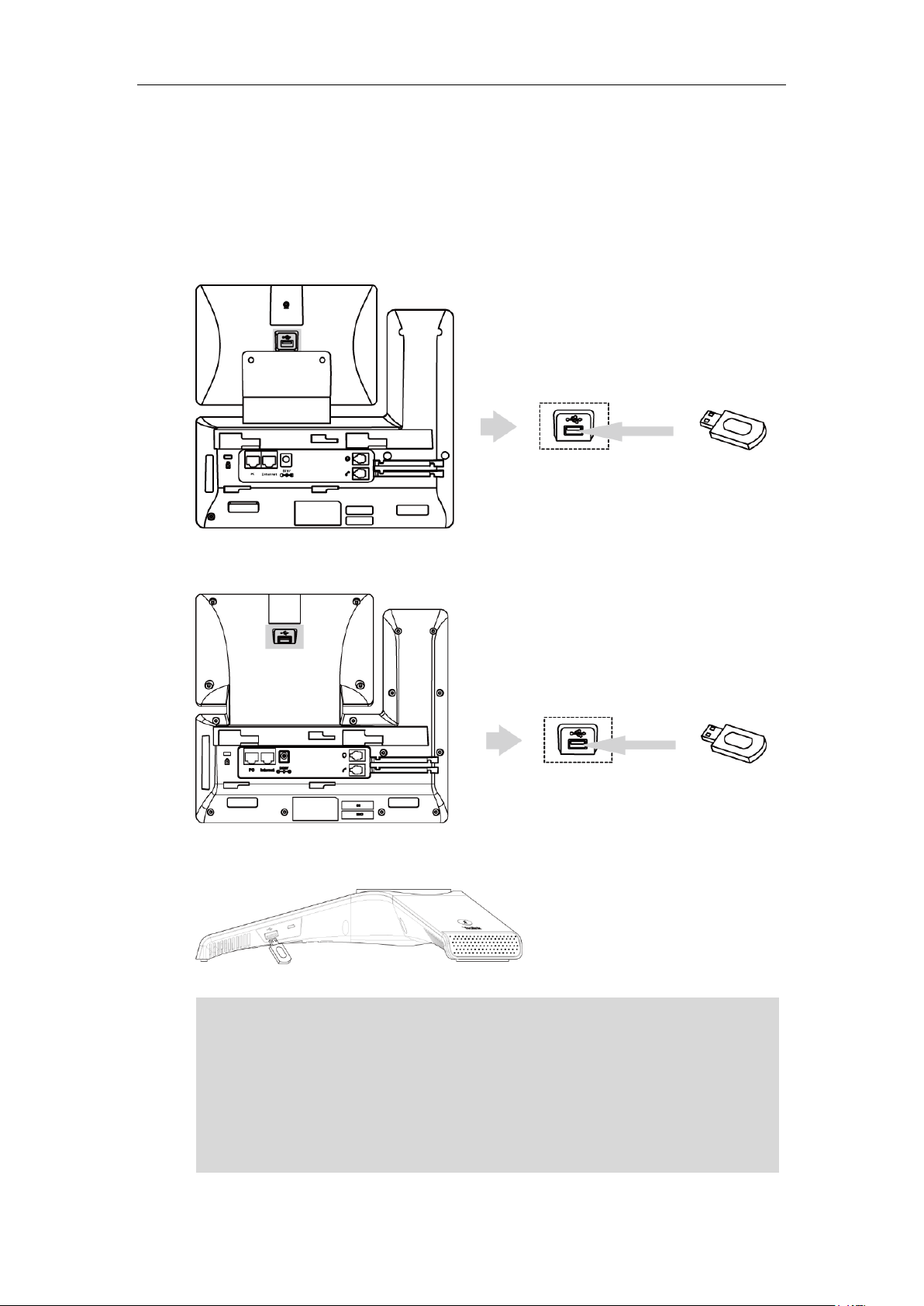
Administrator’s Guide for SIP-T5 Series Smart Media Phones
For SIP-T58V/T58A/T56A, the USB port (on the rear of the phone) can also be used to connect
wireless mic CPW90. For more information, refer to
Yealink CP960 User Guide
.
Connecting the Optional USB Flash Drive
To connect a USB flash drive:
1) Insert a USB flash drive into the USB port on the phone.
For SIP-T58V/A:
Note
For SIP-T56A:
For CP960:
color-screen expansion module EXP50 or USB headset. The IP phone officially supports certain
USB headset models. For more information, refer to
IP Phone
.
Tested headset list compatible with Yealink
For more information on how to use EXP50, refer to
information on how to use USB headset, refer to the documentation from the manufacturer.
18
For CP960, the USB port can also be used to connect wireless mic charging cradle to charge the
Yealink EXP50 User Guide
. For more

Getting Started
Connecting the Wired Expansion MIC CPE90 (Only Applicable
to CP960 IP Phones)
You can connect optional wired expansion MIC CPE90 to enhance the room coverage of the
conference phone.
To connect the wired expansion MIC CPE90:
1) Connect the free end of the optional CPE90 cable to one of the MIC ports on the IP phone.
Connecting the Optional PC using a Micro USB Cable (Only
Applicable to CP960 IP Phones)
You can connect a PC to listen to the PC audio using your CP960 IP phone.
To connect a PC:
1. Connect the micro USB port of the IP phone and the USB port of the PC using a micro USB
cable.
19

Administrator’s Guide for SIP-T5 Series Smart Media Phones
Connecting the Optional External Speaker (Only Applicable to
CP960 IP Phones)
To connect an optional external speaker:
1. Connect the 3.5mm audio-out port of the IP phone to the external speaker using a 3.5mm
jack cable.
Initialization Process Overview
The initialization process of the IP phone is responsible for network connectivity and operation
of the IP phone in your local network.
Once you connect your IP phone to the network and to an electrical supply, the IP phone begins
its initialization process.
During the initialization process, the following events take place:
Loading the ROM file
The ROM file resides in the flash memory of the IP phone. The IP phone comes from the factory
with a ROM file preloaded. During initialization, the IP phone runs a bootstrap loader that loads
and executes the ROM file.
Configuring the VLAN
If the IP phone is connected to a switch, the switch notifies the IP phone of the VLAN
information defined on the switch (if using LLDP or CDP). The IP phone can then proceed with
the DHCP request for its network settings (if using DHCP). For more information on VLAN, refer
to VLAN on page 53.
20
Querying the DHCP (Dynamic Host Configuration Protocol) Server
The IP phone is capable of querying a DHCP server. DHCP is enabled on the IP phone by default.
The following network parameters can be obtained from the DHCP server during initialization:
IP Address

Getting Started
Subnet Mask
Gateway
Primary DNS (Domain Name Server)
Secondary DNS
You need to configure network parameters of the IP phone manually if any of them is not
supplied by the DHCP server. For more information on configuring network parameters
manually, refer to Configuring Network Parameters Manually on page 32.
Contacting the provisioning server
If the IP phone is configured to obtain configurations from the provisioning server, it will
connect to the provisioning server and download the configuration file(s) during startup. The IP
phone will be able to resolve and update configurations written in the configuration file(s). If the
IP phone does not obtain configurations from the provisioning server, the IP phone will use
configurations stored in the flash memory. For more information, refer to Setting Up Your
Phones with a Provisioning Server on page 110.
Updating firmware
If the access URL of firmware is defined in the configuration file, the IP phone will download
firmware from the provisioning server. If the MD5 value of the downloaded firmware file differs
from that of the image stored in the flash memory, the IP phone will perform a firmware update.
You can manually upgrade firmware if the IP phone does not download firmware from the
provisioning server. For more information, refer to Upgrading Firmware on page 124.
Downloading the resource files
In addition to configuration file(s), the IP phone may require resource files before it can deliver
service. These resource files are optional, but if some particular features are being deployed,
these files are required.
The followings show examples of resource files:
Language packs
Ring tones
Contact files
For more information on resource files, refer to Resource Files on page 118.
Verifying Startup
After connected to the power and network, the IP phone begins the initializing process by
cycling through the following steps:
1. The power indicator LED/mute indicator LED illuminates solid red.
2. The message “Welcome Initializing… Please wait” appears on the touch screen when the IP
phone starts up.
21

Administrator’s Guide for SIP-T5 Series Smart Media Phones
3. The main touch screen displays the following:
Time and date
Android keys (for SIP-T58V/T58A/T56A)
Pre-installed applications (for CP960)
4. Tap Settings->Status to check the IP phone status, the touch screen displays the valid IP
address, MAC address, firmware version, etc.
If the IP phone has successfully passed through these steps, it starts up properly and is ready for
use.
22

Setting Up Your System
This section describes essential information on how to set up your phone network and set up
your phones with a provisioning server. It also provides instructions on how to set up a
provisioning server, how to deploy Yealink IP phones from the provisioning server, how to
upgrade firmware, and how to keep user personalized settings after auto provisioning.
This chapter provides the following sections:
Setting Up Your Phone Network
Setting Up Your Phones with a Provisioning Server
Setting Up Your Phone Network
Setting Up Your System
Yealink IP phones operate on an Ethernet local area network (LAN) or wireless network. Local
area network design varies by organization and Yealink IP phones can be configured to
accommodate a number of network designs.
In order to get your IP phones running, you must perform basic network setup, such as IP
address and subnet mask configuration. You can configure the IPv4 or IPv6 network parameters
for the phone. You can also configure the appropriate security (VLAN and/or 802.1X
authentication) and Quality of Service (QoS) settings for the IP phone.
This chapter describes how to configure all the network parameters for IP phones, and it
provides the following sections:
DHCP
DHCP Option
Configuring Network Parameters Manually
PPPoE
Configuring Transmission Methods of the Internet Port and PC Port
Configuring PC Port Mode
Web Server Type
Wi-Fi
VLAN
IPv6 Support
VPN
Configuring the IP Phone for Use with a Firewall or NAT
Quality of Service (QoS)
802.1X Authentication
23

Administrator’s Guide for SIP-T5 Series Smart Media Phones
Central Provisioning
(Configuration File)
<MAC>.cfg
Configure DHCP on the IP phone.
Parameter:
static.network.internet_port.type
Web User Interface
Configure DHCP on the IP phone.
Navigate to:
http://<phoneIPAddress>/servlet?m=mod_dat
a&p=network&q=load
Phone User Interface
Configure DHCP on the IP phone.
Parameter
Permitted Values
Default
static.network.internet_port.type
0, 1 or 2
0
Description:
Configures the Internet port type for IPv4.
0-DHCP
1-PPPoE
2-Static IP Address
Note: It works only if the value of the parameter “static.network.ip_address_mode” is set to 0
(IPv4) or 2 (IPv4 & IPv6). If you change this parameter, the IP phone will reboot to make the
change take effect.
Web User Interface:
Network->Basic->IPv4 Config
Phone User Interface:
Settings->Advanced (default password: admin) ->Network->WAN Port->IPv4->Type
DHCP
DHCP (Dynamic Host Configuration Protocol) is a network protocol used to dynamically allocate
network parameters to network hosts. The automatic allocation of network parameters to hosts
eases the administrative burden of maintaining an IP network. IP phones comply with the DHCP
specifications documented in RFC 2131. If using DHCP, IP phones connected to the network
become operational without having to be manually assigned IP addresses and additional
network parameters.
Procedure
DHCP can be configured using the following methods.
Details of Configuration Parameter:
24

To configure DHCP via web user interface:
Central Provisioning
(Configuration File)
<y0000000000xx>.c
fg
Configure the static DNS feature.
Parameter:
static.network.static_dns_enable
<MAC>.cfg
Configure static DNS address.
1. Click on Network->Basic.
2. In the IPv4 Config block, mark the DHCP radio box.
Setting Up Your System
3. Click Confirm to accept the change.
A dialog box pops up to prompt that settings will take effect after a reboot.
4. Click OK to reboot the phone.
To configure DHCP via phone user interface:
1. Tap Settings->Advanced (default password: admin) ->Network->WAN Port->IPv4.
2. Tap the Type field.
3. Tap DHCP in the pop-up dialog box.
4. Tap to accept the change.
5. Tap OK to reboot the phone.
Static DNS
Static DNS address(es) can be configured and used even though DHCP is enabled.
Procedure
The phone prompts you to reboot the phone.
The settings will take effect after a reboot.
Static DNS can be configured using the following methods.
25

Administrator’s Guide for SIP-T5 Series Smart Media Phones
Parameters:
static.network.primary_dns
static.network.secondary_dns
Web User Interface
Configure the static DNS feature.
Configure static DNS address.
Navigate to:
http://<phoneIPAddress>/servlet?m=mod_
data&p=network&q=load
Phone User Interface
Configure the static DNS feature.
Configure static DNS address.
Parameters
Permitted Values
Default
static.network.static_dns_enable
0 or 1
0
Description:
Triggers the static DNS feature to on or off.
0-Off
1-On
If it is set to 0 (Off), the IP phone will use the IPv4 DNS obtained from DHCP.
If it is set to 1 (On), the IP phone will use manually configured static IPv4 DNS.
Note: It works only if the value of the parameter “static.network.internet_port.type” is set to
0 (DHCP). If you change this parameter, the IP phone will reboot to make the change take
effect.
Web User Interface:
Network->Basic->IPv4 Config->Static DNS
Phone User Interface:
Settings->Advanced (default password: admin)->Network->WAN Port->IPv4->Type (DHCP)
->Static DNS
static.network.primary_dns
IPv4 Address
Blank
Description:
Configures the primary IPv4 DNS server.
Example:
static.network.primary_dns = 202.101.103.55
Note: It works only if the value of the parameter "static.network.static_dns_enable" is set to 1
Details of Configuration Parameters:
26

Setting Up Your System
Parameters
Permitted Values
Default
(On). If you change this parameter, the IP phone will reboot to make the change take effect.
Web User Interface:
Network->Basic->IPv4 Config->Static IP Address->Primary DNS
Phone User Interface:
Settings->Advanced (default password: admin) ->Network->WAN Port->IPv4->Static DNS
(Enabled) ->Primary DNS
static.network.secondary_dns
IPv4 Address
Blank
Description:
Configures the secondary IPv4 DNS server.
Example:
static.network.secondary_dns = 202.101.103.54
Note: It works only if the value of the parameter "static.network.static_dns_enable" is set to 1
(On). If you change this parameter, the IP phone will reboot to make the change take effect.
Web User Interface:
Network->Basic->IPv4 Config->Static IP Address->Secondary DNS
Phone User Interface:
Settings->Advanced (default password: admin) ->Network->WAN Port->IPv4->Static DNS
(Enabled) ->Secondary DNS
To configure static DNS address when DHCP is used via web user interface:
1. Click on Network->Basic.
2. In the IPv4 Config block, mark the DHCP radio box.
3. In the Static DNS block, mark the On radio box.
4. Enter the desired values in the Primary DNS and Secondary DNS fields.
27

Administrator’s Guide for SIP-T5 Series Smart Media Phones
Parameter
DHCP Option
Description
Subnet Mask
1
Specify the client’s subnet mask.
Time Offset
2
Specify the offset of the client's subnet in seconds
from Coordinated Universal Time (UTC).
Router
3
Specify a list of IP addresses for routers on the
client’s subnet.
Time Server
4
Specify a list of time servers available to the client.
Domain Name
Server
6
Specify a list of domain name servers available to
the client.
Log Server
7
Specify a list of MIT-LCS UDP servers available to
the client.
Host Name
12
Specify the name of the client.
5. Click Confirm to accept the change.
A dialog box pops up to prompt that settings will take effect after a reboot.
6. Click OK to reboot the phone.
To configure static DNS when DHCP is used via phone user interface:
1. Tap Settings->Advanced (default password: admin) ->Network->WAN Port->IPv4.
2. Tap the Type field.
3. Tap DHCP in the pop-up dialog box.
4. Tap the Static DNS field.
5. Tap Enabled in the pop-up dialog box.
6. Enter the desired value in the Primary DNS and Secondary DNS field respectively.
7. Tap to accept the change.
The phone prompts you to reboot the phone.
8. Tap OK to reboot the phone.
The settings will take effect after a reboot.
DHCP Option
DHCP provides a framework for passing information to TCP/IP network devices. Network and
other control information are carried in tagged data items that are stored in the options field of
the DHCP message. The data items themselves are also called options.
DHCP can be initiated by simply connecting the IP phone with the network. IP phones broadcast
DISCOVER messages to request the network information carried in DHCP options, and the
DHCP server responds with specific values in corresponding options.
The following table lists common DHCP options supported by IP phones.
28

Setting Up Your System
Parameter
DHCP Option
Description
Domain Server
15
Specify the domain name that client should use
when resolving hostnames via DNS.
Broadcast Address
28
Specify the broadcast address in use on the
client's subnet.
Network Time
Protocol Servers
42
Specify a list of NTP servers available to the client
by IP address.
Vendor-Specific
Information
43
Identify the vendor-specific information.
Vendor Class
Identifier
60
Identify the vendor type.
TFTP Server Name
66
Identify a TFTP server when the 'sname' field in
the DHCP header has been used for DHCP
options.
Boot file Name
67
Identify a boot file when the 'file' field in the
DHCP header has been used for DHCP options.
Central Provisioning
<y0000000000xx>.c
Configure DHCP active.
For more information on DHCP options, refer to RFC 2131 or RFC 2132.
If you do not have the ability to configure the DHCP options for discovering the provisioning
server on the DHCP server, an alternate method of automatically discovering the provisioning
server address is required. Connecting to the secondary DHCP server that responds to DHCP
INFORM queries with a requested provisioning server address is one possibility. For more
information, refer to RFC 3925. If a single alternate DHCP server responds, this is functionally
equivalent to the scenario where the primary DHCP server responds with a valid provisioning
server address. If no DHCP servers respond, the INFORM query process will retry and eventually
time out.
DHCP Option 66 and Option 43
Yealink IP phones support obtaining the provisioning server address by detecting DHCP options
during startup.
The phone will automatically detect the option 66 and option 43 for obtaining the provisioning
server address. DHCP option 66 is used to identify the TFTP server. DHCP option 43 is a
vendor-specific option, which is used to transfer the vendor-specific information.
To use DHCP option 66 or DHCP option 43, make sure the DHCP Active feature is enabled.
Procedure
DHCP active can be configured using the following methods.
29
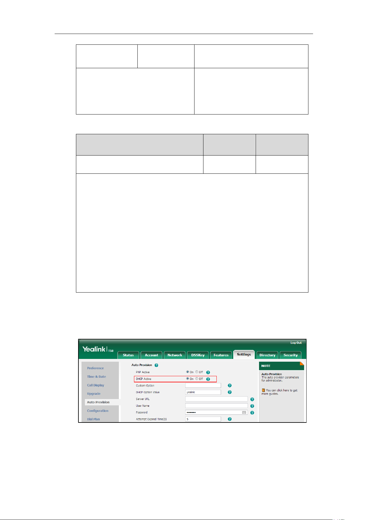
Administrator’s Guide for SIP-T5 Series Smart Media Phones
(Configuration File)
fg
Parameter:
static.auto_provision.dhcp_option.enable
Web User Interface
Configure DHCP active.
Navigate to:
http://<phoneIPAddress>/servlet?m=mod_
data&p=settings-autop&q=load
Parameter
Permitted Values
Default
static.auto_provision.dhcp_option.enable
0 or 1
1
Description:
Triggers the DHCP active feature to on or off.
0-Off
1-On
If it is set to 1 (On), the IP phone will obtain the provisioning server address by detecting
DHCP options.
Web User Interface:
Settings->Auto Provision->DHCP Active
Phone User Interface:
None
Details of Configuration Parameter:
To configure the DHCP active feature via web user interface:
1. Click on Settings->Auto Provision.
2. Mark the On radio box in the DHCP Active field.
DHCP Option 42 and Option 2
30
3. Click Confirm to accept the change.
Yealink IP phones support using the NTP server address offered by DHCP.

DHCP option 42 is used to specify a list of NTP servers available to the client by IP address. NTP
Central Provisioning
(Configuration File)
<y0000000000xx>.
cfg
Configure the DHCP option 12 hostname.
Parameter:
static.network.dhcp_host_name
Web User Interface
Configure the DHCP option 12 hostname.
Navigate to:
http://<phoneIPAddress>/servlet?m=mod_d
ata&p=features-general&q=load
Parameter
Permitted Values
Default
static.network.dhcp_host_name
String within 99
characters
Refer to the
following
content
Description:
Configures the DHCP option 12 hostname on the IP phone.
For SIP-T58V/A IP phones:
The default value is SIP-T58.
For SIP-T56A IP phones:
The default value is SIP-T56A.
For CP960 IP phones:
The default value is SIP-CP960.
Note: If you change this parameter, the IP phone will reboot to make the change take effect.
Web User Interface:
Features->General Information->DHCP Hostname
servers should be listed in order of preference. DHCP option 2 is used to specify the offset of the
client’s subnet in seconds from Coordinated Universal Time (UTC).
To update time with the offset time offered by the DHCP server, make sure the DHCP Time
feature is enabled at the web path Settings->Time & Date->DHCP Time. For more
information on how to configure DHCP time feature, refer to NTP Time Server on page 189.
DHCP Option 12 Hostname on the IP Phone
This option specifies the host name of the client. The name may or may not be qualified with the
local domain name (based on RFC 2132). See RFC 1035 for character restrictions.
Procedure
DHCP option 12 hostname can be configured using the following methods.
Setting Up Your System
Details of Configuration Parameter:
31

Administrator’s Guide for SIP-T5 Series Smart Media Phones
Parameter
Permitted Values
Default
Phone User Interface:
None
To configure DHCP option 12 hostname on the IP phone via web user interface:
1. Click on Features->General Information.
2. Enter the desired host name in the DHCP Hostname field.
3. Click Confirm to accept the change.
A dialog box pops up to prompt that settings will take effect after a reboot.
4. Click OK to reboot the phone.
Configuring Network Parameters Manually
If DHCP is disabled or IP phones cannot obtain network parameters from the DHCP server, you
need to configure them manually. The following parameters should be configured for IP phones
to establish network connectivity:
IP Address
Subnet Mask
Default Gateway
Primary DNS
Secondary DNS
32

Setting Up Your System
Central Provisioning
(Configuration File)
<MAC>.cfg
Configure network parameters of the IP
phone manually.
Parameters:
static.network.internet_port.type
static.network.ip_address_mode
static.network.internet_port.ip
static.network.internet_port.mask
static.network.internet_port.gateway
static.network.primary_dns
static.network.secondary_dns
Web User Interface
Configure network parameters of the IP
phone manually.
Navigate to:
http://<phoneIPAddress>/servlet?m=mod_
data&p=network&q=load
Phone User Interface
Configure network parameters of the IP
phone manually.
Parameters
Permitted Values
Default
static.network.internet_port.type
0, 1 or 2
0
Description:
Configures the Internet port type for IPv4.
0-DHCP
1-PPPoE
2-Static IP Address
Note: It works only if the value of the parameter “static.network.ip_address_mode” is set to 0
(IPv4) or 2 (IPv4 & IPv6). If you change this parameter, the IP phone will reboot to make the
change take effect.
Web User Interface:
Network->Basic->IPv4 Config
Phone User Interface:
Settings->Advanced (default password: admin) ->Network->WAN Port->IPv4->Type
Procedure
Network parameters can be configured manually using the following methods.
Details of Configuration Parameters:
33

Administrator’s Guide for SIP-T5 Series Smart Media Phones
Parameters
Permitted Values
Default
static.network.ip_address_mode
0, 1 or 2
0
Description:
Configures the IP address mode.
0-IPv4
1-IPv6
2-IPv4 & IPv6
Note: If you change this parameter, the IP phone will reboot to make the change take effect.
Web User Interface:
Network->Basic->Internet Port->Mode(IPv4/IPv6)
Phone User Interface:
Settings->Advanced (default password: admin) ->Network->WAN Port->IP Mode
static.network.internet_port.ip
IPv4 Address
Blank
Description:
Configures the IPv4 address.
Example:
static.network.internet_port.ip = 192.168.1.20
Note: It works only if the value of the parameter “static.network.ip_address_mode” is set to 0
(IPv4) or 2 (IPv4 & IPv6), and “static.network.internet_port.type” is set to 2 (Static IP Address).
If you change this parameter, the IP phone will reboot to make the change take effect.
Web User Interface:
Network->Basic->IPv4 Config->Static IP Address->IP Address
Phone User Interface:
Settings->Advanced (default password: admin) ->Network->WAN Port->IPv4->Type (Static
IP) ->IP Address
static.network.internet_port.mask
Subnet Mask
Blank
Description:
Configures the IPv4 subnet mask.
Example:
static.network.internet_port.mask = 255.255.255.0
Note: It works only if the value of the parameter “static.network.ip_address_mode” is set to 0
(IPv4) or 2 (IPv4 & IPv6), and “static.network.internet_port.type” is set to 2 (Static IP Address).
If you change this parameter, the IP phone will reboot to make the change take effect.
Web User Interface:
34

Setting Up Your System
Parameters
Permitted Values
Default
Network->Basic->IPv4 Config->Static IP Address->Subnet Mask
Phone User Interface:
Settings->Advanced (default password: admin) ->Network->WAN Port->IPv4->Type (Static
IP) ->Subnet Mask
static.network.internet_port.gateway
IPv4 Address
Blank
Description:
Configures the IPv4 default gateway.
Example:
static.network.internet_port.gateway = 192.168.1.254
Note: It works only if the value of the parameter “static.network.ip_address_mode” is set to 0
(IPv4) or 2 (IPv4 & IPv6), and “static.network.internet_port.type” is set to 2 (Static IP Address).
If you change this parameter, the IP phone will reboot to make the change take effect.
Web User Interface:
Network->Basic->IPv4 Config->Static IP Address->Gateway
Phone User Interface:
Settings->Advanced (default password: admin) ->Network->WAN Port->IPv4->Type (Static
IP) ->Gateway
static.network.primary_dns
IPv4 Address
Blank
Description:
Configures the primary IPv4 DNS server.
Example:
static.network.primary_dns = 202.101.103.55
Note: It works only if the value of the parameter “static.network.ip_address_mode” is set to 0
(IPv4) or 2 (IPv4 & IPv6), and “static.network.internet_port.type” is set to 2 (Static IP Address).
If you change this parameter, the IP phone will reboot to make the change take effect.
Web User Interface:
Network->Basic->IPv4 Config->Static IP Address->Primary DNS
Phone User Interface:
Settings->Advanced (default password: admin) ->Network->WAN Port->IPv4->Type (Static
IP) ->Primary DNS
static.network.secondary_dns
IPv4 Address
Blank
Description:
Configures the secondary IPv4 DNS server.
35

Administrator’s Guide for SIP-T5 Series Smart Media Phones
Parameters
Permitted Values
Default
Example:
static.network.secondary_dns = 202.101.103.54
Note: It works only if the value of the parameter “static.network.ip_address_mode” is set to 0
(IPv4) or 2 (IPv4 & IPv6), and “static.network.internet_port.type” is set to 2 (Static IP Address).
If you change this parameter, the IP phone will reboot to make the change take effect.
Web User Interface:
Network->Basic->IPv4 Config->Static IP Address->Secondary DNS
Phone User Interface:
Settings->Advanced (default password: admin) ->Network->WAN Port->IPv4->Type (Static
IP) ->Secondary DNS
To configure the IP address mode via web user interface:
1. Click on Network->Basic.
2. Select desired value Mode(IPv4/IPv6).
3. Click Confirm to accept the change.
A dialog box pops up to prompt that settings will take effect after a reboot.
4. Click OK to reboot the phone.
To configure a static IPv4 address via web user interface:
1. Click on Network->Basic.
2. In the IPv4 Config block, mark the Static IP Address radio box.
36

Setting Up Your System
3. Enter the desired values in the IP Address, Subnet Mask, Gateway, Primary DNS and
Secondary DNS fields.
4. Click Confirm to accept the change.
A dialog box pops up to prompt that settings will take effect after a reboot.
5. Click OK to reboot the phone.
To configure the IP address mode via phone user interface:
1. Tap Settings->Advanced (default password: admin) ->Network->WAN Port.
2. Tap the Type field.
3. Tap IPv4 or IPv4 and IPv6 in the pop-up dialog box.
4. Tap to accept the change.
The phone prompts you to reboot the phone.
5. Tap OK to reboot the phone.
The settings will take effect after a reboot.
To configure a static IPv4 address via phone user interface:
1. Tap Settings->Advanced (default password: admin) ->Network->WAN Port->IPv4.
2. Tap the Type field.
3. Tap Static IP in the pop-up dialog box.
4. Enter the desired value in the IP Address, Subnet Mask, Gateway, Primary DNS and
Secondary DNS field respectively.
5. Tap to accept the change.
The phone prompts you to reboot the phone.
6. Tap OK to reboot the phone.
The settings will take effect after a reboot.
37

Administrator’s Guide for SIP-T5 Series Smart Media Phones
Central Provisioning
(Configuration File)
<MAC>.cfg
Configure PPPoE on the IP phone.
Parameter:
static.network.internet_port.type
<y0000000000xx>.c
fg
Configure the user name and password for
PPPoE on the IP phone.
Parameters:
static.network.pppoe.user
static.network.pppoe.password
Web User Interface
Configure PPPoE on the IP phone.
Configure the user name and password for
PPPoE on the IP phone.
Navigate to:
http://<phoneIPAddress>/servlet?m=mod_
data&p=network&q=load
Phone User Interface
Configure PPPoE on the IP phone.
Configure the user name and password for
PPPoE on the IP phone.
Parameters
Permitted
Values
Default
static.network.internet_port.type
0, 1 or 2
0
Description:
Configures the Internet port type for IPv4.
0-DHCP
1-PPPoE
2-Static IP Address
PPPoE
PPPoE (Point-to-Point Protocol over Ethernet) is a network protocol used by Internet Service
Providers (ISPs) to provide Digital Subscriber Line (DSL) high speed Internet services. PPPoE
allows an office or building-full of users to share a common DSL connection to the Internet.
PPPoE connection is supported by the IP phone Internet port. Contact your ISP for the PPPoE
user name and password.
Procedure
PPPoE can be configured using the following methods.
Details of Configuration Parameters:
38

Setting Up Your System
Parameters
Permitted
Values
Default
Note: It works only if the value of the parameter “static.network.ip_address_mode” is set to
0 (IPv4) or 2 (IPv4 & IPv6). If you change this parameter, the IP phone will reboot to make
the change take effect.
Web User Interface:
Network->Basic->IPv4 Config
Phone User Interface:
Settings->Advanced (default password: admin) ->Network->WAN Port->IPv4->Type
static.network.pppoe.user
String within
32 characters
Blank
Description:
Configures the user name for PPPoE connection.
Example:
static.network.pppoe.user = Xmyl0592123
Note: It works only if the value of the parameter “static.network.ip_address_mode” is set to
0 (IPv4) or 2 (IPv4 & IPv6), and “static.network.internet_port.type” is set to 1 (PPPoE). If you
change this parameter, the IP phone will reboot to make the change take effect.
Web User Interface:
Network->Basic->IPv4 Config->PPPoE->User Name
Phone User Interface:
Settings->Advanced (default password: admin) ->Network->WAN Port->IPv4->Type
(PPPoE) ->PPPoE User
static.network.pppoe.password
String within
99 characters
Blank
Description:
Configures the password for PPPoE connection.
Example:
static.network.pppoe.password = yealink123
Note: It works only if the value of the parameter “static.network.ip_address_mode” is set to
0 (IPv4) or 2 (IPv4 & IPv6), and “static.network.internet_port.type” is set to 1 (PPPoE). If you
change this parameter, the IP phone will reboot to make the change take effect.
Web User Interface:
Network->Basic->IPv4 Config->PPPoE->Password
Phone User Interface:
Settings->Advanced (default password: admin) ->Network->WAN Port->IPv4->Type
(PPPoE) ->PPPoE Password
39

Administrator’s Guide for SIP-T5 Series Smart Media Phones
To configure PPPoE via web user interface:
1. Click on Network->Basic.
2. In the IPv4 Config block, mark the PPPoE radio box.
3. Enter the user name and password in corresponding fields.
4. Click Confirm to accept the change.
A dialog box pops up to prompt that settings will take effect after a reboot.
5. Click OK to reboot the phone.
To configure PPPoE via phone user interface:
1. Tap Settings->Advanced (default password: admin) ->Network->WAN Port->IPv4.
2. Tap the Type field.
3. Tap PPPoE in the pop-up dialog box.
4. Enter the user name and password in corresponding fields.
5. Tap to accept the change.
The phone prompts you to reboot the phone.
6. Tap OK to reboot the phone.
The settings will take effect after a reboot.
Configuring Transmission Methods of the Internet Port and PC
Port
40
Yealink SIP-T58V/T58A/T56A IP phones support two Ethernet ports: Internet port and PC port.
You can enable or disable the PC port on the IP phones. The CP960 IP phones have Internet port
only. Three optional methods of transmission configuration for IP phone Internet port or PC
port:
Auto-negotiate

Setting Up Your System
Half-duplex
Full-duplex
Auto-negotiate is configured for both Internet and PC ports on the IP phone by default.
Auto-negotiate
Auto-negotiate means that two connected devices choose common transmission parameters
(e.g., speed and duplex mode) to transmit voice or data over Ethernet. This process entails
devices first sharing transmission capabilities and then selecting the highest performance
transmission mode supported by both. You can configure the Internet port and PC port on the
IP phone to automatically negotiate during the transmission.
Half-duplex
Half-duplex transmission refers to transmitting voice or data in both directions, but in one
direction at a time; this means one device can send data on the line, but not receive data
simultaneously. You can configure the half-duplex transmission on both Internet port and PC
port for the IP phone to transmit in 10Mbps or 100Mbps.
41

Administrator’s Guide for SIP-T5 Series Smart Media Phones
Central Provisioning
(Configuration File)
<y0000000000xx>.c
fg
Configure the transmission methods of the
Ethernet ports.
Parameters:
static.network.internet_port.speed_duplex
static.network.pc_port.speed_duplex
Web User Interface
Configure the transmission methods of the
Ethernet ports.
Navigate to:
http://<phoneIPAddress>/servlet?m=mod_
data&p=network-adv&q=load
Parameters
Permitted Values
Default
static.network.internet_port.speed_duplex
0, 1, 2, 3, 4 or 5
0
Description:
Configures the transmission method of the Internet port.
0-Auto Negotiate
1-Full Duplex 10Mbps
2-Full Duplex 100Mbps
Full-duplex
Full-duplex transmission refers to transmitting voice or data in both directions at the same time;
this means one device can send data on the line while receiving data. You can configure the
full-duplex transmission on both Internet port and PC port for the IP phone to transmit in
10Mbps, 100Mbps or 1000Mbps (1000Mbps is not applicable to CP960 IP phones).
Procedure
The transmission methods of Ethernet ports can be configured using the following methods.
Details of Configuration Parameters:
42

Setting Up Your System
Parameters
Permitted Values
Default
3-Half Duplex 10Mbps
4-Half Duplex 100Mbps
5-Full Duplex 1000Mbps (not applicable to CP960 IP phones)
Note: You can set the transmission speed to 1000Mbps/Auto Negotiate to transmit in
1000Mbps if the IP phone is connected to the switch supports Gigabit Ethernet. We
recommend that you do not change this parameter. If you change this parameter, the IP
phone will reboot to make the change take effect.
Web User Interface:
Network->Advanced->Port Link->WAN Port Link
Phone User Interface:
None
static.network.pc_port.speed_duplex
0, 1, 2, 3 ,4 or 5
0
Description:
Configures the transmission method of the PC port.
0-Auto Negotiate
1-Full Duplex 10Mbps
2-Full Duplex 100Mbps
3-Half Duplex 10Mbps
4-Half Duplex 100Mbps
5-Full Duplex 1000Mbps
Note: It works only if the value of the parameter “static.network.pc_port.enable” is set to 1
(Auto Negotiate). It is not applicable to CP960 IP phones. You can set the transmission
speed to 1000Mbps/Auto Negotiate to transmit in 1000Mbps if the IP phone is connected
to the switch supports Gigabit Ethernet. We recommend that you do not change this
parameter. If you change this parameter, the IP phone will reboot to make the change take
effect.
Web User Interface:
Network->Advanced->Port Link->PC Port Link
Phone User Interface:
None
To configure the transmission methods of Ethernet ports via web user interface:
1. Click on Network->Advanced.
2. Select the desired value from the pull-down list of WAN Port Link.
43

Administrator’s Guide for SIP-T5 Series Smart Media Phones
Central Provisioning
(Configuration File)
<y0000000000xx>.cf
g
Configure the PC port.
Parameter:
static.network.pc_port.enable
Web User Interface
Configure the PC port.
Navigate to:
http://<phoneIPAddress>/servlet?m=m
od_data&p=network-pcport&q=load
3. Select the desired value from the pull-down list of PC Port Link.
4. Click Confirm to accept the change.
A dialog box pops up to prompt that settings will take effect after a reboot.
5. Click OK to reboot the phone.
Configuring PC Port Mode
The PC port on the back of the IP phone is used to connect a PC. You can enable or disable the
PC port on the IP phones via web user interface or using configuration files. PC port is not
applicable to CP960 IP phones.
Procedure
PC port can be configured using the following methods.
44

Details of Configuration Parameter:
Parameter
Permitted Values
Default
static.network.pc_port.enable
0 or 1
1
Description:
Enables or disables the PC port.
0-Disabled
1-Auto Negotiate
Note: If you change this parameter, the IP phone will reboot to make the change take effect.
It is not applicable to CP960 IP phones.
Web User Interface:
Network->PC Port->PC Port Active
Phone User Interface:
None
Setting Up Your System
To enable the PC port via web user interface:
1. Click on Network->PC Port.
2. Select Auto Negotiate from the pull-down list of PC Port Active.
3. Click Confirm to accept the change.
A dialog box pops up to prompt that settings will take effect after a reboot.
4. Click OK to reboot the phone.
To disable the PC port via web user interface:
1. Click on Network->PC Port.
45

Administrator’s Guide for SIP-T5 Series Smart Media Phones
2. Select Disabled from the pull-down list of PC Port Active.
3. Click Confirm to accept the change.
A dialog box pops up to prompt that settings will take effect after a reboot.
4. Click OK to reboot the phone.
Web Server Type
Users can configure the user or administrator features of the phone via web user interface. Web
server type determines access protocol of the IP phone’s web user interface. IP phones support
both HTTP and HTTPS protocols for accessing the web user interface through a web browser
such as Microsoft’s IE, Mozilla Firefox, Google Chrome and etc. This can be disabled when it is
not needed or when it poses a security threat. For more information on accessing the web user
interface, refer to Web User Interface on page 113.
HTTP is an application protocol that runs on top of the TCP/IP suite of protocols. HTTPS is a web
protocol that encrypts and decrypts user page requests as well as pages returned by the web
server. Both HTTP and HTTPS port numbers are configurable.
When you enable user to access web user interface of the IP phone using the HTTP/HTTPS
protocol (take HTTPS protocol for example):
46

Setting Up Your System
Central Provisioning
(Configuration File)
<y0000000000xx>.cfg
Configure the web access type,
HTTP port and HTTPS port.
Parameters:
static.wui.http_enable
static.network.port.http
static.wui.https_enable
static.network.port.https
Web User Interface
Configure the web access type,
HTTP port and HTTPS port.
Navigate to:
http://<phoneIPAddress>/servlet?m
=mod_data&p=network-adv&q=loa
d
Phone User Interface
Configure the web access type,
HTTP port and HTTPS port.
Parameters
Permitted
Values
Default
static.wui.http_enable
0 or 1
1
When you disable user to access web user interface of the IP phone using the HTTP/HTTPS
protocol (take HTTPS protocol for example):
Procedure
Web server type can be configured using the following methods.
Details of Configuration Parameters:
47

Administrator’s Guide for SIP-T5 Series Smart Media Phones
Parameters
Permitted
Values
Default
Description:
Enables or disables the user to access web user interface of the IP phone using the HTTP
protocol.
0-Disabled
1-Enabled
Note: If you change this parameter, the IP phone will reboot to make the change take
effect.
Web User Interface:
Network->Advanced->Web Server->HTTP
Phone User Interface:
Settings->Advanced (default password: admin) ->Network->Webserver Type->HTTP
Status
static.network.port.http
Integer from 1
to 65535
80
Description:
Configures the HTTP port for the user to access web user interface of the IP phone using
the HTTP protocol.
Note: Please take care when choosing an alternate port. If you change this parameter, the
IP phone will reboot to make the change take effect.
Web User Interface:
Network->Advanced->Web Server->HTTP Port (1~65535)
Phone User Interface:
Settings->Advanced (default password: admin) ->Network->Webserver Type->HTTP Port
static.wui.https_enable
0 or 1
1
Description:
Enables or disables the user to access web user interface of the IP phone using the HTTPS
protocol.
0-Disabled
1-Enabled
Note: If you change this parameter, the IP phone will reboot to make the change take
effect.
Web User Interface:
Network->Advanced->Web Server->HTTPS
Phone User Interface:
48

Setting Up Your System
Parameters
Permitted
Values
Default
Settings->Advanced (default password: admin) ->Network->Webserver Type->HTTPS
Status
static.network.port.https
Integer from 1
to 65535
443
Description:
Configures the HTTPS port for the user to access web user interface of the IP phone using
the HTTPS protocol.
Note: Please take care when choosing an alternate port. If you change this parameter, the
IP phone will reboot to make the change take effect.
Web User Interface:
Network->Advanced->Web Server->HTTPS Port (1~65535)
Phone User Interface:
Settings->Advanced (default password: admin) ->Network->Webserver Type->HTTPS
Port
To configure web server type via web user interface:
1. Click on Network->Advanced.
2. Select the desired value from the pull-down list of HTTP.
3. Enter the desired HTTP port number in the HTTP Port (1~65535) field.
The default HTTP port number is 80.
4. Select the desired value from the pull-down list of HTTPS.
5. Enter the desired HTTPS port number in the HTTPS Port (1~65535) field.
49

Administrator’s Guide for SIP-T5 Series Smart Media Phones
The default HTTPS port number is 443.
6. Click Confirm to accept the change.
A dialog box pops up to prompt that settings will take effect after a reboot.
7. Click OK to reboot the phone.
To configure web server type via phone user interface:
1. Tap Settings->Advanced (default password: admin) ->Network->Webserver Type.
2. Tap the HTTP Status field.
3. Tap Enabled in the pop-up dialog box.
4. Enter the desired HTTP port number in the HTTP Port field.
5. Tap the HTTPS Status field.
6. Tap Enabled in the pop-up dialog box.
7. Enter the desired HTTPS port number in the HTTPS Port field.
8. Tap to accept the change.
The phone prompts you to reboot the phone.
9. Tap OK to reboot the phone.
Wi-Fi
50
The settings will take effect after a reboot.
Wi-Fi feature enables users to connect their phones to the organization’s wireless network. The
wireless network is more convenient and cost-effective than wired network.
When the Wi-Fi feature is enabled, the IP phone will automatically scan the available wireless

networks. All the available wireless networks will display in scanning list on the touch screen.
Configuration File
<y0000000000xx>.cfg
Configure Wi-Fi feature.
Parameter:
static.wifi.enable
Local
Phone User Interface
Configure Wi-Fi feature.
Configure the Wi-Fi settings.
Parameter
Permitted Values
Default
static.wifi.enable
0 or 1
0
Description:
Enables or disables the Wi-Fi feature.
0-Disabled
1-Enabled
Web User Interface:
None
Phone User Interface:
For SIP-T58V/T58A/T56A IP phones, you have to disable the Wi-Fi feature if you want to use the
wired network.
Yealink IP phones support connecting to 2.4G wireless network.
Note
The following advices you need to know when using the IP phones in the wireless
network:
a) Check whether the wireless network is normal when the account registers failed or
sometimes there is no sound during an active call.
b) Ensure that the bandwidth of your wireless network is able to provide stable and real-time
data transmission otherwise the quality of video calls may be affected. We recommend you
to use the wired network for video calls.
c) We recommend you do not use the unstable router product in your home/office
environment.
Setting Up Your System
d) We recommend you to set the password for the wireless network so as to ensure the
network resource will not be occupied by the unknown user.
Procedure
Wi-Fi feature can be configured using the configuration files or locally.
Details of the Configuration Parameter:
51

Administrator’s Guide for SIP-T5 Series Smart Media Phones
Parameter
Permitted Values
Default
Settings->Basic->Wi-Fi->Wi-Fi
To enable the Wi-Fi feature via phone user interface:
1. Swipe down from the top of the screen or swipe left/right to go to the second idle screen.
2. Tap Settings->Basic->Wi-Fi.
3. Tap the On radio box in the Wi-Fi field.
The phone will automatically search for available wireless networks in your area.
To add a wireless network:
1. Swipe down from the top of the screen or swipe left/right to go to the second idle screen.
2. Tap Settings->Basic->Wi-Fi.
3. Tap the On radio box in the Wi-Fi field.
4. Tap and then tap Add.
5. Enter the desired value in the Network SSID field.
6. Tap the Security field.
7. Tap the desired value in the pop-up dialog box.
- If you select WEP or WPA/WPA2 PSK:
1) Enter the password in the Password field.
- If you select 802.1x EAP:
1) Tap the EAP method field.
2) Tap the desired EAP method in the pop-up dialog box.
- If you select PEAP/TTLS:
a) Tap the Phase-2 authentication field.
b) Tap the desired Phase-2 authentication method in the pop-up dialog
box.
c) Enter the identity (username) in the Identity field.
d) Enter the anonymous identity (username) in the Anonymous identity
field (to be used as the unencrypted identity).
e) Enter the password in the Password field.
52
- If you select TLS:
a) Enter the username in the Identity field
- If you select PWD:
a) Enter the username in the Identity field.
b) Enter the password in the Password field.
8. You can do the following:
- Tap the Show password checkbox to make the password visible.

VLAN
Central Provisioning
(Configuration File)
<y0000000000xx>.cfg
Configure the VLAN assignment
method.
Parameter:
static.network.vlan.vlan_change.ena
ble
Parameter
Permitted
Values
Default
static.network.vlan.vlan_change.enable
0 or 1
0
Description:
Enables or disables the IP phone to obtain VLAN ID using lower priority of VLAN
assignment method or disable VLAN feature when the IP phone cannot obtain VLAN ID
using the current VLAN assignment method.
Setting Up Your System
- Tap the Show advanced options checkbox to configure the HTTP proxy for Browser
application.
9. Tap Save to accept the change.
VLAN (Virtual Local Area Network) is used to logically divide a physical network into several
broadcast domains. VLAN membership can be configured through software instead of
physically relocating devices or connections. Grouping devices with a common set of
requirements regardless of their physical location can greatly simplify network design. VLANs
can address issues such as scalability, security and network management.
The purpose of VLAN configurations on the IP phone is to insert tag with VLAN information to
the packets generated by the IP phone. When VLAN is properly configured for the ports
(Internet port and PC port) on the IP phone, the IP phone will tag all packets from these ports
with the VLAN ID. The switch receives and forwards the tagged packets to the corresponding
VLAN according to the VLAN ID in the tag as described in IEEE Std 802.3.
VLAN on IP phones allows simultaneous access for a regular PC. This feature allows a PC to be
daisy chained to an IP phone and the connection for both PC and IP phone to be trunked
through the same physical Ethernet cable.
In addition to manual configuration, the IP phone also supports automatic discovery of VLAN
via LLDP, CDP or DHCP. The assignment takes effect in this order: assignment via LLDP/CDP,
manual configuration, then assignment via DHCP.
For more information on VLAN, refer to
VLAN assignment method can be configured using the following methods.
VLAN Feature on Yealink IP Phones
.
Details of Configuration Parameter:
53

Administrator’s Guide for SIP-T5 Series Smart Media Phones
Parameter
Permitted
Values
Default
0-Disabled
1-Enabled
The priority of each method is: LLDP/CDP>Manual>DHCP VLAN.
If it is set to 1 (Enabled), the IP phone will attempt to use the lower priority of VLAN
assignment method when failing to obtain the VLAN ID using higher priority of VLAN
assignment method. If all the methods are attempted, the phone will disable VLAN
feature.
Note: If you change this parameter, the IP phone will reboot to make the change take
effect.
Web User Interface:
None
Phone User Interface:
None
Central Provisioning
(Configuration File)
<y0000000000xx>.cfg
Configure LLDP feature.
Parameters:
static.network.lldp.enable
static.network.lldp.packet_interval
Web User Interface
Configure LLDP feature.
Navigate to:
http://<phoneIPAddress>/servlet?
LLDP
LLDP (Linker Layer Discovery Protocol) is a vendor-neutral Link Layer protocol, which allows IP
phones to receive and/or transmit device-related information from/to directly connected
devices on the network that are also using the protocol, and store the information about other
devices.
When LLDP feature is enabled on IP phones, the IP phones periodically advertise their own
information to the directly connected LLDP-enabled switch. The IP phones can also receive LLDP
packets from the connected switch. When the application type is “voice”, IP phones decide
whether to update the VLAN configurations obtained from the LLDP packets. When the VLAN
configurations on the IP phones are different from the ones sent by the switch, the IP phones
perform an update and reboot. This allows the IP phones to be plugged into any switch, obtain
their VLAN IDs, and then start communications with the call control.
Procedure
LLDP can be configured using the following methods.
54

m=mod_data&p=network-adv&q
=load
Phone User Interface
Configure LLDP feature.
Setting Up Your System
55

Administrator’s Guide for SIP-T5 Series Smart Media Phones
Parameters
Permitted Values
Default
static.network.lldp.enable
0 or 1
1
Description:
Enables or disables the LLDP (Linker Layer Discovery Protocol) feature on the IP phone.
0-Disabled
1-Enabled
If it is set to 1 (Enabled), the IP phone will attempt to determine its VLAN ID through
LLDP.
Note: If you change this parameter, the IP phone will reboot to make the change take
effect.
Web User Interface:
Network->Advanced->LLDP->Active
Phone User Interface:
Settings->Advanced (default password: admin) ->Network->LLDP->LLDP Status
static.network.lldp.packet_interval
Integer from 1 to
3600
60
Description:
Configures the interval (in seconds) for the IP phone to send the LLDP (Linker Layer
Discovery Protocol) request.
Note: It works only if the value of the parameter “static.network.lldp.enable” is set to 1
(Enabled). If you change this parameter, the IP phone will reboot to make the change
take effect.
Web User Interface:
Network->Advanced->LLDP->Packet Interval (1~3600s)
Phone User Interface:
Settings->Advanced (default password: admin) ->Network->LLDP->Packet Interval
Details of Configuration Parameters:
56
To configure LLDP feature via web user interface:
1. Click on Network->Advanced.
2. In the LLDP block, select the desired value from the pull-down list of Active.

Setting Up Your System
3. Enter the desired time interval in the Packet Interval (1~3600s) field.
CDP
4. Click Confirm to accept the change.
A dialog box pops up to prompt that settings will take effect after a reboot.
5. Click OK to reboot the phone.
To configure LLDP feature via phone user interface:
1. Tap Settings->Advanced (default password: admin) ->Network->LLDP.
2. Tap the On radio box in the LLDP Status field.
3. Enter the priority value (1-3600s) in the Packet Interval field.
4. Tap to accept the change.
The phone prompts you to reboot the phone.
5. Tap OK to reboot the phone.
The settings will take effect after a reboot.
CDP (Cisco Discovery Protocol) allows IP phones to receive and/or transmit device-related
information from/to directly connected devices on the network that are also using the protocol,
and store the information about other devices.
When CDP feature is enabled on IP phones, the IP phones periodically advertise their own
information to the directly connected CDP-enabled switch. The IP phones can also receive CDP
packets from the connected switch. When the VLAN configurations on the IP phones are
different from the ones sent by the switch, the IP phones perform an update and reboot. This
allows the IP phones to be plugged into any switch, obtain their VLAN IDs, and then start
communications with the call control.
57

Administrator’s Guide for SIP-T5 Series Smart Media Phones
Central Provisioning
(Configuration File)
<y0000000000xx>.cfg
Configure CDP feature.
Parameters:
static.network.cdp.enable
static.network.cdp.packet_interval
Web User Interface
Configure CDP feature.
Navigate to:
http://<phoneIPAddress>/servlet?m
=mod_data&p=network-adv&q=loa
d
Phone User Interface
Configure CDP feature.
Parameters
Permitted Values
Default
static.network.cdp.enable
0 or 1
0
Description:
Enables or disables the CDP (Cisco Discovery Protocol) feature on the IP phone.
0-Disabled
1-Enabled
If it is set to 1 (Enabled), the IP phone will attempt to determine its VLAN ID through CDP.
Note: If you change this parameter, the IP phone will reboot to make the change take
effect.
Web User Interface:
Network->Advanced->CDP->Active
Phone User Interface:
Settings->Advanced (default password: admin) ->Network->CDP->CDP Status
static.network.cdp.packet_interval
Integer from 1 to
3600
60
Description:
Configures the interval (in seconds) for the IP phone to send the CDP (Cisco Discovery
Protocol) request.
Note: It works only if the value of the parameter “static.network.cdp.enable” is set to 1
(Enabled). If you change this parameter, the IP phone will reboot to make the change take
Procedure
CDP can be configured using the following methods.
Details of Configuration Parameters:
58

Setting Up Your System
Parameters
Permitted Values
Default
effect.
Web User Interface:
Network->Advanced->CDP->Packet Interval (1~3600s)
Phone User Interface:
Settings->Advanced (default password: admin) ->Network->CDP->Packet Interval
To configure CDP via web user interface:
1. Click on Network->Advanced.
2. In the CDP block, select the desired value from the pull-down list of Active.
3. Enter the desired time interval in the Packet Interval (1~3600s) field.
4. Click Confirm to accept the change.
A dialog box pops up to prompt that settings will take effect after a reboot.
5. Click OK to reboot the phone.
To configure CDP feature via phone user interface:
1. Tap Settings->Advanced (default password: admin) ->Network->CDP->CDP Status.
2. Tap the On radio box in the CDP Status field.
3. Enter the priority value (1-3600s) in the Packet Interval field.
4. Tap to accept the change.
The phone prompts you to reboot the phone.
5. Tap OK to reboot the phone.
The settings will take effect after a reboot.
59

Administrator’s Guide for SIP-T5 Series Smart Media Phones
Central
Provisioning
(Configuration File)
<y0000000000xx>.cfg
Configure VLAN for the Internet port and
PC port manually.
Parameters:
static.network.vlan.internet_port_enable
static.network.vlan.internet_port_vid
static.network.vlan.internet_port_priority
static.network.vlan.pc_port_enable
static.network.vlan.pc_port_vid
static.network.vlan.pc_port_priority
Web User Interface
Configure VLAN for the Internet port and
PC port manually.
Navigate to:
http://<phoneIPAddress>/servlet?m=mo
d_data&p=network-adv&q=load
Phone User Interface
Configure VLAN for the Internet port and
PC port manually.
Parameters
Permitted
Values
Default
static.network.vlan.internet_port_enable
0 or 1
0
Description:
Enables or disables VLAN for the Internet port.
0-Disabled
1-Enabled
Note: If you change this parameter, the IP phone will reboot to make the change take
effect.
Web User Interface:
Network->Advanced->VLAN->WAN Port->Active
Manual Configuration for VLAN in the Wired Network
VLAN is disabled on IP phones by default. You can configure VLAN for the Internet port and PC
port manually. For CP960 IP phones, you can only configure VLAN for the Internet port manually,
because they only have Internet port. Before configuring VLAN on the IP phone, you need to
obtain the VLAN ID from your network administrator.
Procedure
VLAN can be configured using the following methods.
Details of Configuration Parameters:
60

Setting Up Your System
Parameters
Permitted
Values
Default
Phone User Interface:
Settings->Advanced (default password: admin) ->Network->VLAN->WAN Port->VLAN
Status
static.network.vlan.internet_port_vid
Integer from 1
to 4094
1
Description:
Configures VLAN ID for the Internet port.
Note: If you change this parameter, the IP phone will reboot to make the change take
effect.
Web User Interface:
Network->Advanced->VLAN->WAN Port->VID (1-4094)
Phone User Interface:
Settings->Advanced (default password: admin) ->Network->VLAN->WAN Port->VID
Number
static.network.vlan.internet_port_priority
Integer from 0
to 7
0
Description:
Configures VLAN priority for the Internet port.
7 is the highest priority, 0 is the lowest priority.
Note: If you change this parameter, the IP phone will reboot to make the change take
effect.
Web User Interface:
Network->Advanced->VLAN->WAN Port->Priority
Phone User Interface:
Settings->Advanced (default password: admin) ->Network->VLAN->WAN Port->Priority
static.network.vlan.pc_port_enable
0 or 1
0
Description:
Enables or disables VLAN for the PC port.
0-Disabled
1-Enabled
Note: It works only if the value of the parameter “static.network.pc_port.enable” is set to
1 (Auto Negotiate). It is not applicable to CP960 IP phones. If you change this parameter,
the IP phone will reboot to make the change take effect.
61

Administrator’s Guide for SIP-T5 Series Smart Media Phones
Parameters
Permitted
Values
Default
Web User Interface:
Network->Advanced->VLAN->PC Port->Active
Phone User Interface:
Settings->Advanced (default password: admin) ->Network->VLAN->PC Port->VLAN
Status
static.network.vlan.pc_port_vid
Integer from 1
to 4094
1
Description:
Configures VLAN ID for the PC port.
Note: It works only if the value of the parameter “static.network.pc_port.enable” is set to
1 (Auto Negotiate). It is not applicable to CP960 IP phones. If you change this parameter,
the IP phone will reboot to make the change take effect.
Web User Interface:
Network->Advanced->VLAN->PC Port->VID (1-4094)
Phone User Interface:
Settings->Advanced (default password: admin) ->Network->VLAN->PC Port->VID
Number
static.network.vlan.pc_port_priority
Integer from 0
to 7
0
Description:
Configures VLAN priority for the PC port.
7 is the highest priority, 0 is the lowest priority.
Note: It works only if the value of the parameter “static.network.pc_port.enable” is set to
1 (Auto Negotiate). It is not applicable to CP960 IP phones. If you change this parameter,
the IP phone will reboot to make the change take effect.
Web User Interface:
Network->Advanced->VLAN >PC Port->Priority
Phone User Interface:
Settings->Advanced (default password: admin) ->Network->VLAN->PC Port->Priority
62
To configure VLAN for Internet port via web user interface:
1. Click on Network->Advanced.
2. In the WAN Port block, select the desired value from the pull-down list of Active.
3. Enter the VLAN ID in the VID (1-4094) field.

4. Select the desired value (0-7) from the pull-down list of Priority.
Setting Up Your System
5. Click Confirm to accept the change.
A dialog box pops up to prompt that the settings will take effect after a reboot.
6. Click OK to reboot the phone.
To configure VLAN for PC port via web user interface:
1. Click on Network->Advanced.
2. In the PC Port block, select the desired value from the pull-down list of Active.
3. Enter the VLAN ID in the VID (1-4094) field.
4. Select the desired value (0-7) from the pull-down list of Priority.
63

Administrator’s Guide for SIP-T5 Series Smart Media Phones
Central Provisioning
(Configuration File)
<y0000000000xx>.cf
g
Configure DHCP VLAN discovery
feature.
Parameters:
static.network.vlan.dhcp_enable
static.network.vlan.dhcp_option
Web User Interface
Configure DHCP VLAN discovery
feature.
Navigate to:
http://<phoneIPAddress>/servlet?m=m
od_data&p=network-adv&q=load
Phone User Interface
Configure DHCP VLAN discovery
feature.
5. Click Confirm to accept the change.
A dialog box pops up to prompt that the settings will take effect after a reboot.
6. Click OK to reboot the phone.
To configure VLAN for Internet port (or PC port) via phone user interface:
1. Tap Settings->Advanced (default password: admin) ->Network->VLAN->WAN Port (or
PC Port).
2. Tap the On radio box in the VLAN Status field.
3. Enter the VLAN ID (1-4094) in the VID Number field.
4. Enter the priority value (0-7) in the Priority field.
5. Tap to accept the change.
The phone prompts you to reboot the phone.
6. Tap OK to reboot the phone.
The settings will take effect after a reboot.
DHCP VLAN
IP phones support VLAN discovery via DHCP. When the VLAN Discovery method is set to DHCP,
the IP phone will examine DHCP option for a valid VLAN ID. The predefined option 132 is used
to supply the VLAN ID by default. You can customize the DHCP option used to request the
VLAN ID.
Procedure
DHCP VLAN can be configured using the following methods.
64

Details of Configuration Parameters:
Parameters
Permitted Values
Default
static.network.vlan.dhcp_enable
0 or 1
1
Description:
Enables or disables DHCP VLAN discovery feature on the IP phone.
0-Disabled
1-Enabled
Note: If you change this parameter, the IP phone will reboot to make the change take
effect.
Web User Interface:
Network->Advanced->VLAN->DHCP VLAN->Active
Phone User Interface:
Settings->Advanced (default password: admin) ->Network->VLAN->DHCP
VLAN->DHCP VLAN
static.network.vlan.dhcp_option
Integer from 1 to
255
132
Description:
Configures the DHCP option from which the IP phone will obtain the VLAN settings. You
can configure at most five DHCP options and separate them by commas.
Note: If you change this parameter, the IP phone will reboot to make the change take
effect.
Web User Interface:
Network->Advanced->VLAN->DHCP VLAN->Option(1-255)
Phone User Interface:
Settings->Advanced (default password: admin) ->Network->VLAN->DHCP
VLAN->Option
Setting Up Your System
To configure DHCP VLAN discovery via web user interface:
1. Click on Network->Advanced.
2. In the DHCP VLAN block, select the desired value from the pull-down list of Active.
3. Enter the desired option in the Option(1-255) field.
65

Administrator’s Guide for SIP-T5 Series Smart Media Phones
The default option is 132.
4. Click Confirm to accept the change.
A dialog box pops up to prompt that settings will take effect after a reboot.
5. Click OK to reboot the phone.
To configure DHCP VLAN discovery via phone user interface:
1. Tap Settings->Advanced (default password: admin) ->Network->VLAN->DHCP VLAN.
2. Tap the On radio box in the DHCP VLAN field.
3. Enter the desired option in the Option field.
4. Tap to accept the change.
The phone prompts you to reboot the phone.
5. Tap OK to reboot the phone.
The settings will take effect after a reboot.
IPv6 Support
Because Internet Protocol version 4 (IPv4) uses a 32-bit address, it cannot meet the increased
demands for unique IP addresses for all devices that connect to the Internet. Therefore, Internet
Protocol version 6 (IPv6) is the next generation network layer protocol, which designed as a
replacement for the current IPv4 protocol.
66
IPv6 is developed by the Internet Engineering Task Force (IETF) to deal with the long-anticipated
problem of IPv4 address exhaustion. Yealink IP Phone supports IPv4 addressing mode, IPv6
addressing mode, as well as an IPv4&IPv6 dual stack addressing mode. IPv4 uses a 32-bit

Setting Up Your System
DHCPv6
SLAAC
(ICMPv6)
How the IP phone obtains the IPv6 address and network
settings?
Disabled
Disabled
You have to manually configure the static IPv6 address and
other network settings.
Disabled
Enabled
The IP phone can obtain the IPv6 address via SLAAC, but the
other network settings must be configured manually.
address, consisting of four groups of three decimal digits separated by dots; for example,
192.168.1.100. IPv6 uses a 128-bit address, consisting of eight groups of four hexadecimal digits
separated by colons; for example, 2026:1234:1:1:215:65ff:fe1f:caa.
VoIP network based on IPv6 can provide end-to-end security capabilities, enhanced Quality of
Service (QoS), a set of service requirements to deliver performance guarantee while transporting
traffic over the network.
If you configure the network settings on the phone for an IPv6 network, you can set up an IP
address for the phone either by using SLAAC (ICMPv6), DHCPv6 or by manually entering an IP
address. Ensure that your network environment supports IPv6. Contact your ISP for more
information.
IPv6 Address Assignment Method
Supported IPv6 address assignment methods:
Manual Assignment: An IPv6 address and other configuration parameters (e.g., DNS
server) for the IP phone can be statically configured by an administrator.
Stateless Address Autoconfiguration (SLAAC)/ ICMPv6: SLAAC is one of the most
convenient methods to assign IP addresses to IPv6 nodes. SLAAC requires no manual
configuration of the IP phone, minimal (if any) configuration of routers, and no additional
servers. To use IPv6 SLAAC, the IP phone must be connected to a network with at least one
IPv6 router connected. This router is configured by the network administrator and sends
out Router Advertisement announcements onto the link. These announcements can allow
the on-link connected IP phone to configure itself with IPv6 address, as specified in RFC
4862.
Stateful DHCPv6: The Dynamic Host Configuration Protocol for IPv6 (DHCPv6) has been
standardized by the IETF through RFC 3315. DHCPv6 enables DHCP servers to pass
configuration parameters such as IPv6 network addresses to IPv6 nodes. It offers the
capability of automatic allocation of reusable network addresses and additional
configuration flexibility. This protocol is a stateful counterpart to “IPv6 Stateless Address
Autoconfiguration” (RFC 2462), and can be used separately or concurrently with the latter
to obtain configuration parameters.
How the IP phone obtains the IPv6 address and network settings?
The following table lists where the IP phone obtains the IPv6 address and other network
settings:
67

Administrator’s Guide for SIP-T5 Series Smart Media Phones
DHCPv6
SLAAC
(ICMPv6)
How the IP phone obtains the IPv6 address and network
settings?
Enabled
Disabled
The IP phone can obtain the IPv6 address and the other
network settings via DHCPv6.
Enabled
Enabled
The IP phone can obtain the IPv6 address via SLAAC and
obtain other network settings via DHCPv6.
Central Provisioning
(Configuration File)
<MAC>.cfg
Configure the IPv6 address assignment
method.
Parameters:
static.network.ip_address_mode
static.network.ipv6_internet_port.type
static.network.ipv6_internet_port.ip
static.network.ipv6_prefix
static.network.ipv6_internet_port.gateway
static.network.ipv6_icmp_v6.enable
Configure the IPv6 static DNS address.
Parameters:
static.network.ipv6_primary_dns
static.network.ipv6_secondary_dns
<y0000000000xx>
.cfg
Configure the IPv6 static DNS.
Parameter:
static.network.ipv6_static_dns_enable
Web User Interface
Configure the IPv6 address assignment
method.
Configure the IPv6 static DNS.
Navigate to:
http://<phoneIPAddress>/servlet?m=mo
d_data&p=network&q=load
Phone User Interface
Configure the IPv6 address assignment
method.
Configure the IPv6 static DNS.
Configure the IPv6 static DNS address.
Procedure
IPv6 can be configured using the following methods.
68

Details of Configuration Parameters:
Parameters
Permitted
Values
Default
static.network.ip_address_mode
0, 1 or 2
0
Description:
Configures the IP address mode.
0-IPv4
1-IPv6
2-IPv4 & IPv6
Note: If you change this parameter, the IP phone will reboot to make the change take
effect.
Web User Interface:
Network->Basic->Internet Port->Mode(IPv4/IPv6)
Phone User Interface:
Settings->Advanced (default password: admin) ->Network->WAN Port->IP Mode
static.network.ipv6_internet_port.type
0 or 1
0
Description:
Configures the Internet port type for IPv6.
0-DHCP
1-Static IP Address
Note: It works only if the value of the parameter “static.network.ip_address_mode” is set
to 1 (IPv6) or 2 (IPv4 & IPv6). If you change this parameter, the IP phone will reboot to
make the change take effect.
Web User Interface:
Network->Basic->IPv6 Config
Phone User Interface:
Settings->Advanced (default password: admin) ->Network->WAN Port->IPv6->Type
static.network.ipv6_static_dns_enable
0 or 1
0
Description:
Triggers the static IPv6 DNS feature to on or off.
0-Off
1-On
Setting Up Your System
69

Administrator’s Guide for SIP-T5 Series Smart Media Phones
If it is set to 0 (Off), the IP phone will use the IPv6 DNS obtained from DHCP.
If it is set to 1 (On), the IP phone will use manually configured static IPv6 DNS.
Note: It works only if the value of the parameter “static.network.ipv6_internet_port.type”
is set to 0 (DHCP). If you change this parameter, the IP phone will reboot to make the
change take effect.
Web User Interface:
Network->Basic->IPv6 Config->IPv6 Static DNS
Phone User Interface:
Settings->Advanced (default: admin) ->Network->WAN Port->IPv6->Type (DHCP)
->Static DNS
static.network.ipv6_internet_port.ip
IPv6 address
Blank
Description:
Configures the IPv6 address.
Example:
static.network.ipv6_internet_port.ip = 2026:1234:1:1:215:65ff:fe1f:caa
Note: It works only if the value of the parameter “static.network.ip_address_mode” is set
to 1 (IPv6) or 2 (IPv4 & IPv6), and "static.network.ipv6_internet_port.type" is set to 1
(Static IP Address). If you change this parameter, the IP phone will reboot to make the
change take effect.
Web User Interface:
Network->Basic->IPv6 Config->Static IP Address->IP Address
Phone User Interface:
Settings->Advanced (default password: admin) ->Network->WAN Port->IPv6->Type
(Static IP) ->IP Address
static.network.ipv6_prefix
Integer from
0 to 128
64
Description:
Configures the IPv6 prefix.
Note: It works only if the value of the parameter “static.network.ip_address_mode” is set
to 1 (IPv6) or 2 (IPv4 & IPv6), and "static.network.ipv6_internet_port.type" is set to 1
(Static IP Address). If you change this parameter, the IP phone will reboot to make the
change take effect.
Web User Interface:
Network->Basic->IPv6 Config->Static IP Address->IPv6 Prefix(0~128)
Phone User Interface:
Settings->Advanced (default password: admin) ->Network->WAN Port->IPv6->Type
70

Setting Up Your System
(Static IP) ->IPv6 IP Prefix
static.network.ipv6_internet_port.gateway
IPv6 address
Blank
Description:
Configures the IPv6 default gateway.
Example:
static.network.ipv6_internet_port.gateway = 3036:1:1:c3c7:c11c:5447:23a6:255
Note: It works only if the value of the parameter “static.network.ip_address_mode” is set
to 1 (IPv6) or 2 (IPv4 & IPv6), and "static.network.ipv6_internet_port.type" is set to 1
(Static IP Address).If you change this parameter, the IP phone will reboot to make the
change take effect.
Web User Interface:
Network->Basic->IPv6 Config->Static IP Address->Gateway
Phone User Interface:
Settings->Advanced (default password: admin) ->Network->WAN Port->IPv6->Type
(Static IP) ->Gateway
static.network.ipv6_primary_dns
IPv6 address
Blank
Description:
Configures the primary IPv6 DNS server.
Example:
static.network.ipv6_primary_dns = 3036:1:1:c3c7: c11c:5447:23a6:256
Note: It works only if the value of the parameter "static.network.ip_address_mode" is set
to 1 (IPv6) or 2 (IPv4 & IPv6). In DHCP environment, you also need to make sure the
value of the parameter "static.network.ipv6_static_dns_enable" is set to 1 (On). If you
change this parameter, the IP phone will reboot to make the change take effect.
Web User Interface:
Network->Basic->IPv6 Config->Static IP Address->Primary DNS
Phone User Interface:
Settings->Advanced (default password: admin) ->Network->WAN Port->IPv6->Type
(Static IP) ->Primary DNS
Or Settings->Advanced (default password: admin) ->Network->WAN Port->IPv6->Type
(DHCP) ->Static DNS (Enabled) ->Primary DNS
static.network.ipv6_secondary_dns
IPv6 address
Blank
Description:
Configures the secondary IPv6 DNS server.
71

Administrator’s Guide for SIP-T5 Series Smart Media Phones
Example:
static.network.ipv6_secondary_dns = 2026:1234:1:1:c3c7:c11c:5447:23a6
Note: It works only if the value of the parameter "static.network.ip_address_mode" is set
to 1 (IPv6) or 2 (IPv4 & IPv6). In DHCP environment, you also need to make sure the
value of the parameter "static.network.ipv6_static_dns_enable" is set to 1 (On). If you
change this parameter, the IP phone will reboot to make the change take effect.
Web User Interface:
Network->Basic->IPv6 Config->Static IP Address->Secondary DNS
Phone User Interface:
Settings->Advanced (default password: admin) ->Network->WAN Port->IPv6->Type
(Static IP) ->Secondary DNS
Or Settings->Advanced (default password: admin) ->Network->WAN Port->IPv6->Type
(DHCP) ->Static DNS (Enabled) ->Secondary DNS
static.network.ipv6_icmp_v6.enable
0 or 1
1
Description:
Enables or disables the IP phone to obtain IPv6 network settings via SLAAC (Stateless
Address Autoconfiguration) method.
0-Disabled
1-Enabled
Note: If you change this parameter, the IP phone will reboot to make the change take
effect.
Web User Interface:
Network->Advanced->ICMPv6 Status->Active
Phone User Interface:
None
To configure IPv6 address assignment method via web user interface:
1. Click on Network->Basic.
2. Select the desired address mode (IPv6 or IPv4 & IPv6) from the pull-down list of
72
Mode(IPv4/IPv6).

Setting Up Your System
3. In the IPv6 Config block, mark the DHCP or the Static IP Address radio box.
- If you mark the Static IP Address radio box, configure the IPv6 address and other
configuration parameters in the corresponding fields.
73

Administrator’s Guide for SIP-T5 Series Smart Media Phones
- (Optional.) If you mark the DHCP radio box, you can configure the static DNS address
in the corresponding fields.
4. Click Confirm to accept the change.
A dialog box pops up to prompt that the settings will take effect after a reboot.
5. Click OK to reboot the phone.
To configure SLAAC feature via web user interface:
1. Click on Network->Advanced.
74

Setting Up Your System
2. In the ICMPv6 Status block, select the desired value from the pull-down list of Active.
3. Click Confirm to accept the change.
A dialog box pops up to prompt that the settings will take effect after a reboot.
4. Click OK to reboot the phone.
To configure IPv6 address assignment method via phone user interface:
1. Tap Settings->Advanced (default password: admin) ->Network->WAN Port.
2. Tap the IP Mode field.
3. Tap IPv6 or IPv4 and IPv6 in the pop-up dialog box.
4. Tap IPv6.
5. Tap the Type field.
6. Tap the desired IPv6 address assignment method in the pop-up dialog box.
If you select the Static IP, configure the IPv6 address and other network parameters in the
corresponding fields.
7. Tap to accept the change.
The phone prompts you to reboot the phone.
8. Tap OK to reboot the phone.
The settings will take effect after a reboot.
To configure static DNS when DHCP is used via phone user interface:
1. Tap Settings->Advanced (default password: admin) ->Network->WAN Port->IPv6.
2. Tap the Type field.
3. Tap DHCP in the pop-up dialog box.
4. Tap the Static DNS field.
75

Administrator’s Guide for SIP-T5 Series Smart Media Phones
5. Tap Enabled in the pop-up dialog box.
6. Enter the desired value in the Primary DNS and Secondary DNS field respectively.
7. Tap to accept the change.
The phone prompts you to reboot the phone.
8. Tap OK to reboot the phone.
The settings will take effect after a reboot.
VPN
VPN (Virtual Private Network) is a secured private network connection built on top of public
telecommunication infrastructure, such as the Internet. It has become more prevalent due to
benefits of scalability, reliability, convenience and security. VPN provides remote offices or
individual users with secure access to their organization's network.
Types of VPN Access
There are two types of VPN access: remote-access VPN (connecting an individual device to a
network) and site-to-site VPN (connecting two networks together). Remote-access VPN allows
employees to access their company's intranet from home or outside the office, and site-to-site
VPN allows employees in geographically separated offices to share one cohesive virtual network.
VPN can be also classified by the protocols used to tunnel the traffic. It provides security
through tunneling protocols: IPSec, SSL, L2TP and PPTP.
VPN Technology
IP phones support SSL VPN, which provides remote-access VPN capabilities through SSL.
OpenVPN is a full featured SSL VPN software solution that creates secure connections in remote
access facilities, designed to work with the TUN/TAP virtual network interface. TUN and TAP are
virtual network kernel devices. TAP simulates a link layer device and provides a virtual
point-to-point connection, while TUN simulates a network layer device and provides a virtual
network segment.
76

Setting Up Your System
VPN files
Description
Unified Directories
ca.crt
CA certificate
/config/openvpn/keys/ca.crt
client.crt
Client certificate
/config/openvpn/keys/client.crt
client.key
Private key of the client
/config/openvpn/keys/client.key
Central
Provisioning
(Configuration File)
<y0000000000xx>.cfg
Configure VPN feature and upload a
TAR file to the IP phone.
Parameters:
static.network.vpn_enable
static.openvpn.url
Web User Interface
Configure VPN feature and upload a
TAR file to the IP phone.
Navigate to:
http://<phoneIPAddress>/servlet?m
=mod_data&p=network-adv&q=loa
d
Phone User Interface
Configure VPN feature.
Parameters
Permitted Values
Default
static.network.vpn_enable
0 or 1
0
Description:
IP phones use OpenVPN to achieve VPN feature. To prevent disclosure of private information,
tunnel endpoints must authenticate each other before secure VPN tunnel is established. After
VPN feature is configured properly on the IP phone, the IP phone acts as a VPN client and uses
the certificates to authenticate the VPN server.
To use VPN, the compressed package of VPN-related files should be uploaded to the IP phone
in advance. The file format of the compressed package must be *.tar. The related VPN files are:
certificates (ca.crt and client.crt), key (client.key) and the configuration file (vpn.cnf) of the VPN
client.
The following table lists the unified directories of the OpenVPN certificates and key in the
configuration file (vpn.cnf) for Yealink IP phones:
For more information, refer to
OpenVPN Feature on Yealink IP phones
Procedure
VPN can be configured using the following methods.
.
Details of Configuration Parameters:
77

Administrator’s Guide for SIP-T5 Series Smart Media Phones
Parameters
Permitted Values
Default
Enables or disables OpenVPN feature on the IP phone.
0-Disabled
1-Enabled
Note: If you change this parameter, the IP phone will reboot to make the change take
effect.
Web User Interface:
Network->Advanced->VPN->Active
Phone User Interface:
Settings->Advanced (default: admin) ->Network->VPN->VPN Active
static.openvpn.url
URL within 511
characters
Blank
Description:
Configures the access URL of the *.tar file for OpenVPN.
Example:
static.openvpn.url = http://192.168.10.25/OpenVPN.tar
Web User Interface:
Network->Advanced->VPN->Upload VPN Config
Phone User Interface:
None
To upload a TAR file and configure VPN via web user interface:
1. Click on Network->Advanced.
78
 Loading...