

Page 1
YASNAC PC NC
Operating Manual
Page 2
YASNAC PC NC Operating Manual Introduction
SAFETY INFORMATION
PRECAUTIONS
1. Read this instruction manual in its entirety before using the programming functions available in the
YASNAC PC NC.
2. The following warning symbols are used to indicate precautions that the user must be aware of to
safely use this equipment. Failure to follow these precautions can result in serious or possibly even
fatal injury and damage to products or related equipment or systems.
WARNING
WARNING
WARNING
This symbol indicates the presence of a potentially hazardous condition which, if not avoided, could
result in serious personal injury or death.
This precautionary symbol appears in labels attached to YASNAC products to alert the user to conditions requiring concern for safety.
SPECIAL SAFETY NOTE: This symbol indicates that ELECTRICAL SHOCK HAZARD con-
dition exists. DO NOT TOUCH any electrical connection terminals when the power is on, and for at
least 5 minutes after switching off the power supply. Warning label is located on the CNC enclosure
as shown:
PC NC Unit
xxxxxxxxx
xxxxxxxxx
xxxxxxxxx
xxxxxxxxx
xxxxxxxxx
WARNING LABEL
NOTICE
Printed _______. 2000. The information contained within this document is the proprietary property of
Yaskawa Electric America, Inc., and may not be copied, reproduced or transmitted to other parties without
the expressed written authorization of Yaskawa Electric America, Inc.
No patent liability is assumed with respect to the uses of the information contained herein. Moreover,
because Yaskawa is constantly improving its high quality product, the information contained in this manual
is subject to change without notice. Every precaution has been taken in the preparation of this document.
Nevertheless, Yaskawa assumes no responsibility for damages resulting from the use of the information contained within this publication.
i
Page 3

YASNAC PC NC Operating Manual Introduction
USING THIS MANUAL
This manual describes the procedures for programming the
RELATED INFORMATION SOURCES
For additional information, refer to the following manuals
TITLE OF DOCUMENT CONTENTS
YASNAC PC NC Operating Manual
(YEA-SIE-C844-2.1)
YASNAC PC NC Programming Manual
(YEA-SIE-C844-2.2)
YASNAC PC NC PLC Pr ogramming Manual
(YEA-SIE-C844-0.1)
YASNAC PC NC I/O Signal Function
(YEA-SIE-C844-2.3)
YASNAC PC NC Connecting Man ual
(YEA-SIE-C844-0.2)
YASNAC PC NC
Basic configuration and operating procedures
PC NC Program creation instructions
PLC Program creation instructions
Describes functions between PC NC and PLC
Instructions for connecting PC NC with machines,
machine interface and peripheral equipment
.
MEMOCON GL120,G130 120 Series
I/O Module User’s Manual
(Document No. SIEZ-C825-20.22)
MEMOCON GL120,G130 Hardware User’s Manual
(Document No. SIEZ-C825-20.1)
YASNAC PC NC Maintenance Manual
(YEA-SIE-C844-2.9)
Describes man-machine-interface (MMI) programming,
specifications and definitions.
Describes I/O power supply specifications
Describes the AC input power supply specifi catio ns for I/O.
Describes service and maintenance procedures.
ii
Page 4

YASNAC PC NC Operating Manual Introduction
INFORMATION INDICATORS
The following symbols are used in this programming manual to emphasize particular information t o the user:
Indicates important information to be remembered, i.e., precautionary alarm displays to prevent damaging devices.
Indicates supplementary material.
Indicates definitions of terminology that has not been explained before.
NOTES REGARDING SAFE OPERATION
It is important that the user should read this manual before installing, operating, performing any
maintenance or inspecting the
YASNAC PC NC.
Also, the functions and performance of a NC machine
tool are not determined by the CNC unit itself, therefore thoroughly read and familiarize yourself with the
machine builder’s documentation concerning the safe and most efficient ways to use the machine tool.
iii
Page 5

YASNAC PC NC Operating Manual Introduction
TABLE OF CONTENTS
Chapter 1
1.1 Outline of the YASNAC System . . . . . . . . . . . . . . . . . . . . . . . . . . . . . . . . . . . . 1-2
1.1.1 System Configuration . . . . . . . . . . . . . . . . . . . . . . . . . . . . . . . . . . . . . . 1-2
1.1.2 Environmental Requirements . . . . . . . . . . . . . . . . . . . . . . . . . . . . . . . . . 1-3
1.1.3 Machine Operation Panel . . . . . . . . . . . . . . . . . . . . . . . . . . . . . . . . . . . . 1-4
1.1.4 General Specifications . . . . . . . . . . . . . . . . . . . . . . . . . . . . . . . . . . . . . . 1-5
1.2 Protective Functions . . . . . . . . . . . . . . . . . . . . . . . . . . . . . . . . . . . . . . . . . . . . . . 1-9
1.2.1 Emergency Stop . . . . . . . . . . . . . . . . . . . . . . . . . . . . . . . . . . . . . . . . . . . 1-9
1.2.2 Overtravel . . . . . . . . . . . . . . . . . . . . . . . . . . . . . . . . . . . . . . . . . . . . . . . . 1-9
1.2.3 Stored Stroke Limit . . . . . . . . . . . . . . . . . . . . . . . . . . . . . . . . . . . . . . . 1-10
Chapter 2
1.2.4 Interlock Inputs . . . . . . . . . . . . . . . . . . . . . . . . . . . . . . . . . . . . . . . . . . 1-11
2.1 General Operation Flow . . . . . . . . . . . . . . . . . . . . . . . . . . . . . . . . . . . . . . . . . . . 2-2
2.2 Inspection Before Turning the Power ON . . . . . . . . . . . . . . . . . . . . . . . . . . . . . 2-3
2.2.1 Inspection of the NC Unit . . . . . . . . . . . . . . . . . . . . . . . . . . . . . . . . . . . 2-4
2.2.2 Preparation before Turning the Power ON . . . . . . . . . . . . . . . . . . . . . . .2- 5
2.3 Turning the Power ON and Inspecting After Power ON . . . . . . . . . . . . . . . . . . 2-6
2.3.1 Procedure for Turning the Power ON . . . . . . . . . . . . . . . . . . . . . . . . . . 2-6
2.3.2 Checking the Motors for Abnormalities . . . . . . . . . . . . . . . . . . . . . . . . 2-7
2.3.3 Procedure for Turning Power OFF . . . . . . . . . . . . . . . . . . . . . . . . . . . . 2-7
2.3.4 Inspection of the Battery . . . . . . . . . . . . . . . . . . . . . . . . . . . . . . . . . . . . 2-8
2.4 Manual Operation (1) . . . . . . . . . . . . . . . . . . . . . . . . . . . . . . . . . . . . . . . . . . . . 2-11
2.4.1 Manual Rapid Traverse (RAPID) . . . . . . . . . . . . . . . . . . . . . . . . . . . . 2-11
2.4.2 Jog Feed (JOG) . . . . . . . . . . . . . . . . . . . . . . . . . . . . . . . . . . . . . . . . . . 2-11
2.4.3 Step Feed (STEP) . . . . . . . . . . . . . . . . . . . . . . . . . . . . . . . . . . . . . . . . . 2-12
2.4.4 Handle Feed (HANDLE)* . . . . . . . . . . . . . . . . . . . . . . . . . . . . . . . . . . 2-12
2.5 Manual Operation (2) . . . . . . . . . . . . . . . . . . . . . . . . . . . . . . . . . . . . . . . . . . . . 2-13
iv
Page 6

YASNAC PC NC Operating Manual Introduction
2.5.1 Simultaneous 2 or 3-axis Handle Feed * . . . . . . . . . . . . . . . . . . . . . . . 2-13
2.5.2 Manual Reference Point Return . . . . . . . . . . . . . . . . . . . . . . . . . . . . . . 2-14
2.5.3 Manual Reference Point Return to the Second Reference Point* . . . . 2-16
2.5.4 1-line MDI . . . . . . . . . . . . . . . . . . . . . . . . . . . . . . . . . . . . . . . . . . . . . . 2-17
2.6 Automatic Operation (1) . . . . . . . . . . . . . . . . . . . . . . . . . . . . . . . . . . . . . . . . . 2-18
2.6.1 Preparation of Automatic Operation . . . . . . . . . . . . . . . . . . . . . . . . . . 2-18
2.6.2 MDI Operation . . . . . . . . . . . . . . . . . . . . . . . . . . . . . . . . . . . . . . . . . . . 2-21
2.6.3 Feed Hold . . . . . . . . . . . . . . . . . . . . . . . . . . . . . . . . . . . . . . . . . . . . . . . 2-21
2.6.4 Override . . . . . . . . . . . . . . . . . . . . . . . . . . . . . . . . . . . . . . . . . . . . . . . . 2-21
2.7 Automatic Operation (2) . . . . . . . . . . . . . . . . . . . . . . . . . . . . . . . . . . . . . . . . . 2-23
2.7.1 Optional Stop . . . . . . . . . . . . . . . . . . . . . . . . . . . . . . . . . . . . . . . . . . . . 2-23
2.7.2 Optional Block Skip . . . . . . . . . . . . . . . . . . . . . . . . . . . . . . . . . . . . . . . 2-23
2.7.3 Dry Run . . . . . . . . . . . . . . . . . . . . . . . . . . . . . . . . . . . . . . . . . . . . . . . . 2-24
Chapter 3
2.7.4 Display Lock and Machine Lock . . . . . . . . . . . . . . . . . . . . . . . . . . . . . 2-24
2.7.5 Auxiliary Function Lock . . . . . . . . . . . . . . . . . . . . . . . . . . . . . . . . . . . 2-25
2.7.6 Z-axis Command Neglect . . . . . . . . . . . . . . . . . . . . . . . . . . . . . . . . . . 2-25
2.7.7 4th-axis Command Neglect . . . . . . . . . . . . . . . . . . . . . . . . . . . . . . . . . 2-25
2.7.8 5th-axis Command Neglect . . . . . . . . . . . . . . . . . . . . . . . . . . . . . . . . . 2-26
2.8 Operation Intervention During Automatic Operation . . . . . . . . . . . . . . . . . . . 2-27
2.8.1 MDI Operation Intervention during Automatic Operation . . . . . . . . . 2-28
2.8.2 Automatic Handle Mode Offset * . . . . . . . . . . . . . . . . . . . . . . . . . . . . 2-28
2.8.3 Manual Absolute . . . . . . . . . . . . . . . . . . . . . . . . . . . . . . . . . . . . . . . . . 2-30
3.1 USER INTERFACE OVERVIEW . . . . . . . . . . . . . . . . . . . . . . . . . . . . . . . . . . 3-7
3.1.1 Status Bar . . . . . . . . . . . . . . . . . . . . . . . . . . . . . . . . . . . . . . . . . . . . . . . . 3-7
3.1.2 Battery Indicator . . . . . . . . . . . . . . . . . . . . . . . . . . . . . . . . . . . . . . . . . . 3-7
3.1.3 NC Execution Status . . . . . . . . . . . . . . . . . . . . . . . . . . . . . . . . . . . . . . . 3-8
3.1.4 Motion Status . . . . . . . . . . . . . . . . . . . . . . . . . . . . . . . . . . . . . . . . . . . . . 3-8
3.1.5 Alarm Message . . . . . . . . . . . . . . . . . . . . . . . . . . . . . . . . . . . . . . . . . . . 3-9
3.1.6 Warning Message . . . . . . . . . . . . . . . . . . . . . . . . . . . . . . . . . . . . . . . . . . 3-9
v
Page 7

YASNAC PC NC Operating Manual Introduction
3.1.7 Time/Date . . . . . . . . . . . . . . . . . . . . . . . . . . . . . . . . . . . . . . . . . . . . . . . 3-11
3.1.8 Mode / MDI / Toolbar . . . . . . . . . . . . . . . . . . . . . . . . . . . . . . . . . . . . . 3-11
3.1.9 Mode Indicator . . . . . . . . . . . . . . . . . . . . . . . . . . . . . . . . . . . . . . . . . . . 3-12
3.1.10 Menu Bar . . . . . . . . . . . . . . . . . . . . . . . . . . . . . . . . . . . . . . . . . . . . . . . 3-18
3.2 RECURRING COMPONENTS . . . . . . . . . . . . . . . . . . . . . . . . . . . . . . . . . . . 3-19
3.2.1 Position Display . . . . . . . . . . . . . . . . . . . . . . . . . . . . . . . . . . . . . . . . . . 3-19
3.2.2 Program Display . . . . . . . . . . . . . . . . . . . . . . . . . . . . . . . . . . . . . . . . . 3-20
3.2.3 Nest Level Display . . . . . . . . . . . . . . . . . . . . . . . . . . . . . . . . . . . . . . . . 3-21
3.2.4 Shortcuts . . . . . . . . . . . . . . . . . . . . . . . . . . . . . . . . . . . . . . . . . . . . . . . . 3-22
3.2.5 Number Field . . . . . . . . . . . . . . . . . . . . . . . . . . . . . . . . . . . . . . . . . . . . 3-22
3.2.6 File Browser . . . . . . . . . . . . . . . . . . . . . . . . . . . . . . . . . . . . . . . . . . . . . 3-23
3.3 RUN MENU . . . . . . . . . . . . . . . . . . . . . . . . . . . . . . . . . . . . . . . . . . . . . . . . . . 3-25
3.3.1 Production Screen . . . . . . . . . . . . . . . . . . . . . . . . . . . . . . . . . . . . . . . . 3-25
3.3.2 Proveout Screen . . . . . . . . . . . . . . . . . . . . . . . . . . . . . . . . . . . . . . . . . . 3-27
3.3.3 NC Switch Screen . . . . . . . . . . . . . . . . . . . . . . . . . . . . . . . . . . . . . . . . 3-33
3.3.4 Timers Screen . . . . . . . . . . . . . . . . . . . . . . . . . . . . . . . . . . . . . . . . . . . 3-34
3.3.5 Tool Path Drawing Screen . . . . . . . . . . . . . . . . . . . . . . . . . . . . . . . . . 3-36
3.4 PROGRAM MENU . . . . . . . . . . . . . . . . . . . . . . . . . . . . . . . . . . . . . . . . . . . . . 3-40
3.4.1 File Screen . . . . . . . . . . . . . . . . . . . . . . . . . . . . . . . . . . . . . . . . . . . . . . 3-40
3.4.2 Editor Screen . . . . . . . . . . . . . . . . . . . . . . . . . . . . . . . . . . . . . . . . . . . . 3-46
3.4.3 List Screen . . . . . . . . . . . . . . . . . . . . . . . . . . . . . . . . . . . . . . . . . . . . . . 3-53
3.4.4 Macro Variables . . . . . . . . . . . . . . . . . . . . . . . . . . . . . . . . . . . . . . . . . . 3-55
3.5 TOOL MENU . . . . . . . . . . . . . . . . . . . . . . . . . . . . . . . . . . . . . . . . . . . . . . . . . 3-57
3.5.1 Offsets Screen . . . . . . . . . . . . . . . . . . . . . . . . . . . . . . . . . . . . . . . . . . . 3-57
3.5.2 Magazine Screen . . . . . . . . . . . . . . . . . . . . . . . . . . . . . . . . . . . . . . . . . 3-59
3.6 SETUP MENU . . . . . . . . . . . . . . . . . . . . . . . . . . . . . . . . . . . . . . . . . . . . . . . . . 3-61
3.6.1 Workshift Screen . . . . . . . . . . . . . . . . . . . . . . . . . . . . . . . . . . . . . . . . . .3-61
3.6.2 Four (4) Positions Screen . . . . . . . . . . . . . . . . . . . . . . . . . . . . . . . . . . . 3-63
3.6.3 One (1) Position Screen . . . . . . . . . . . . . . . . . . . . . . . . . . . . . . . . . . . . 3-64
3.7 UTILITIES MENU . . . . . . . . . . . . . . . . . . . . . . . . . . . . . . . . . . . . . . . . . . . . . 3-65
3.7.1 Login Screen . . . . . . . . . . . . . . . . . . . . . . . . . . . . . . . . . . . . . . . . . . . . 3-65
vi
Page 8

YASNAC PC NC Operating Manual Introduction
3.7.2 PC Settings Screen . . . . . . . . . . . . . . . . . . . . . . . . . . . . . . . . . . . . . . . . 3-67
3.7.3 Maintenance Screen . . . . . . . . . . . . . . . . . . . . . . . . . . . . . . . . . . . . . . 3-69
3.7.4 Configuration Screen . . . . . . . . . . . . . . . . . . . . . . . . . . . . . . . . . . . . . . 3-70
3.7.5 Backup and Restore Screen . . . . . . . . . . . . . . . . . . . . . . . . . . . . . . . . . 3-72
3.7.6 CPU Monitor Screen . . . . . . . . . . . . . . . . . . . . . . . . . . . . . . . . . . . . . . 3-74
3.7.7 Setting Parameters Screen . . . . . . . . . . . . . . . . . . . . . . . . . . . . . . . . . . 3-75
3.7.8 NC Parameters Screen . . . . . . . . . . . . . . . . . . . . . . . . . . . . . . . . . . . . 3-78
3.7.9 Machine Setup Screen . . . . . . . . . . . . . . . . . . . . . . . . . . . . . . . . . . . . . 3-79
3.7.10 Pitch Error Screen . . . . . . . . . . . . . . . . . . . . . . . . . . . . . . . . . . . . . . . . 3-80
3.7.11 Solid Tap Screen . . . . . . . . . . . . . . . . . . . . . . . . . . . . . . . . . . . . . . . . . 3-82
3.7.12 Torque Ripple Screen . . . . . . . . . . . . . . . . . . . . . . . . . . . . . . . . . . . . . 3-83
3.7.13 Parameter Search Screen . . . . . . . . . . . . . . . . . . . . . . . . . . . . . . . . . . . 3-84
3.7.14 High Speed Cutting Screen . . . . . . . . . . . . . . . . . . . . . . . . . . . . . . . . . 3-86
3.7.15 User Install Screen . . . . . . . . . . . . . . . . . . . . . . . . . . . . . . . . . . . . . . . 3-87
3.7.16 MTB Install Screen . . . . . . . . . . . . . . . . . . . . . . . . . . . . . . . . . . . . . . . 3-90
3.7.17 PLC Parameters Screen . . . . . . . . . . . . . . . . . . . . . . . . . . . . . . . . . . . . 3-91
3.7.18 PLC Diagnosis Screen . . . . . . . . . . . . . . . . . . . . . . . . . . . . . . . . . . . . . 3-92
3.7.19 Ladder Monitor Screen . . . . . . . . . . . . . . . . . . . . . . . . . . . . . . . . . . . . 3-97
3.7.20 Switch Label Screen . . . . . . . . . . . . . . . . . . . . . . . . . . . . . . . . . . . . . . . 3-97
3.8 ALARM MENU . . . . . . . . . . . . . . . . . . . . . . . . . . . . . . . . . . . . . . . . . . . . . . 3-100
3.8.1 NC Alarm Screen . . . . . . . . . . . . . . . . . . . . . . . . . . . . . . . . . . . . . . . 3-100
3.8.2 PLC Alarm Screen . . . . . . . . . . . . . . . . . . . . . . . . . . . . . . . . . . . . . . 3-101
3.8.3 Alarm History Screen . . . . . . . . . . . . . . . . . . . . . . . . . . . . . . . . . . . . 3-102
3.9 HELP MENU . . . . . . . . . . . . . . . . . . . . . . . . . . . . . . . . . . . . . . . . . . . . . . . . . 3-104
3.9.1 MMI Map Screen . . . . . . . . . . . . . . . . . . . . . . . . . . . . . . . . . . . . . . . 3-104
3.9.2 Manual Screen . . . . . . . . . . . . . . . . . . . . . . . . . . . . . . . . . . . . . . . . . . 3-105
3.9.3 About Screen . . . . . . . . . . . . . . . . . . . . . . . . . . . . . . . . . . . . . . . . . . . 3-106
3.10 OFF LINE MODE . . . . . . . . . . . . . . . . . . . . . . . . . . . . . . . . . . . . . . . . . . . . . 3-107
3.10.1 The Offline Mode Interface . . . . . . . . . . . . . . . . . . . . . . . . . . . . . . . 3-107
vii
Page 9

YASNAC PC NC Operating Manual Introduction
Chapter 4
4.1 MAINTENANCE DATA . . . . . . . . . . . . . . . . . . . . . . . . . . . . . . . . . . . . . . . . . 4-2
4.1.1 Checking the Status of Problems . . . . . . . . . . . . . . . . . . . . . . . . . . . . . . 4-2
4.1.2 Checking the NC Information . . . . . . . . . . . . . . . . . . . . . . . . . . . . . . . . 4-3
4.1.3 Display of Alarm Information. . . . . . . . . . . . . . . . . . . . . . . . . . . . . . . . . 4-3
4.1.4 Cause of Alarm and Corrective Action . . . . . . . . . . . . . . . . . . . . . . . . . 4-4
4.1.5 Troubleshooting (1) . . . . . . . . . . . . . . . . . . . . . . . . . . . . . . . . . . . . . . . . 4-5
4.1.6 Troubleshooting (2) . . . . . . . . . . . . . . . . . . . . . . . . . . . . . . . . . . . . . . . 4-11
4.1.7 Alarms Not Indicated by Alarm Numbers . . . . . . . . . . . . . . . . . . . . . . 4-15
4.1.8 PC NC Alarms Not Indicated By Alarm Numbers . . . . . . . . . . . . . . . 4-26
4.1.9 Touch Screen Maintenance . . . . . . . . . . . . . . . . . . . . . . . . . . . . . . . . . 4-27
4.1.10 Mode of Operation of PC NC . . . . . . . . . . . . . . . . . . . . . . . . . . . . . . . 4-27
4.1.11 Self - Diagnosis Function Specification . . . . . . . . . . . . . . . . . . . . . . . . 4-28
4.1.12 Hard Drive Mounting Replacement . . . . . . . . . . . . . . . . . . . . . . . . . . . 4-29
viii
Page 10

YASNAC PC NC Operating Manual Chapter 1: Outline of the YASNAC System
1
Outline of the YASNAC System
Chapter 1 describes the outline of the YASNAC system and the operating
features and functions that should be thoroughly understood for the safe
and efficient operation of the system.
1.1 Outline of the YASNAC System . . . . . . . . . . . . . . . . . . . . . . . . . . . . . . . . . . . . 1-2
1.1.1 System Configuration . . . . . . . . . . . . . . . . . . . . . . . . . . . . . . . . . . . . . . .1-2
1.1.2 Environmental Requirements . . . . . . . . . . . . . . . . . . . . . . . . . . . . . . . . .1-3
1.1.3 Machine Operation Panel . . . . . . . . . . . . . . . . . . . . . . . . . . . . . . . . . . . . .1-4
1.1.4 General Specifications . . . . . . . . . . . . . . . . . . . . . . . . . . . . . . . . . . . . . . .1-5
1.2 Protective Functions . . . . . . . . . . . . . . . . . . . . . . . . . . . . . . . . . . . . . . . . . . . . . 1-9
1.2.1 Emergency Stop . . . . . . . . . . . . . . . . . . . . . . . . . . . . . . . . . . . . . . . . . . . .1-9
1.2.2 Overtravel . . . . . . . . . . . . . . . . . . . . . . . . . . . . . . . . . . . . . . . . . . . . . . . . .1-9
1.2.3 Stored Stroke Limit . . . . . . . . . . . . . . . . . . . . . . . . . . . . . . . . . . . . . . . .1-10
1.2.4 Interlock Inputs . . . . . . . . . . . . . . . . . . . . . . . . . . . . . . . . . . . . . . . . . . .1-11
1 - 1
Page 11
YASNAC PC NC Operating Manual Chapter 1: Outline of the YASNAC System
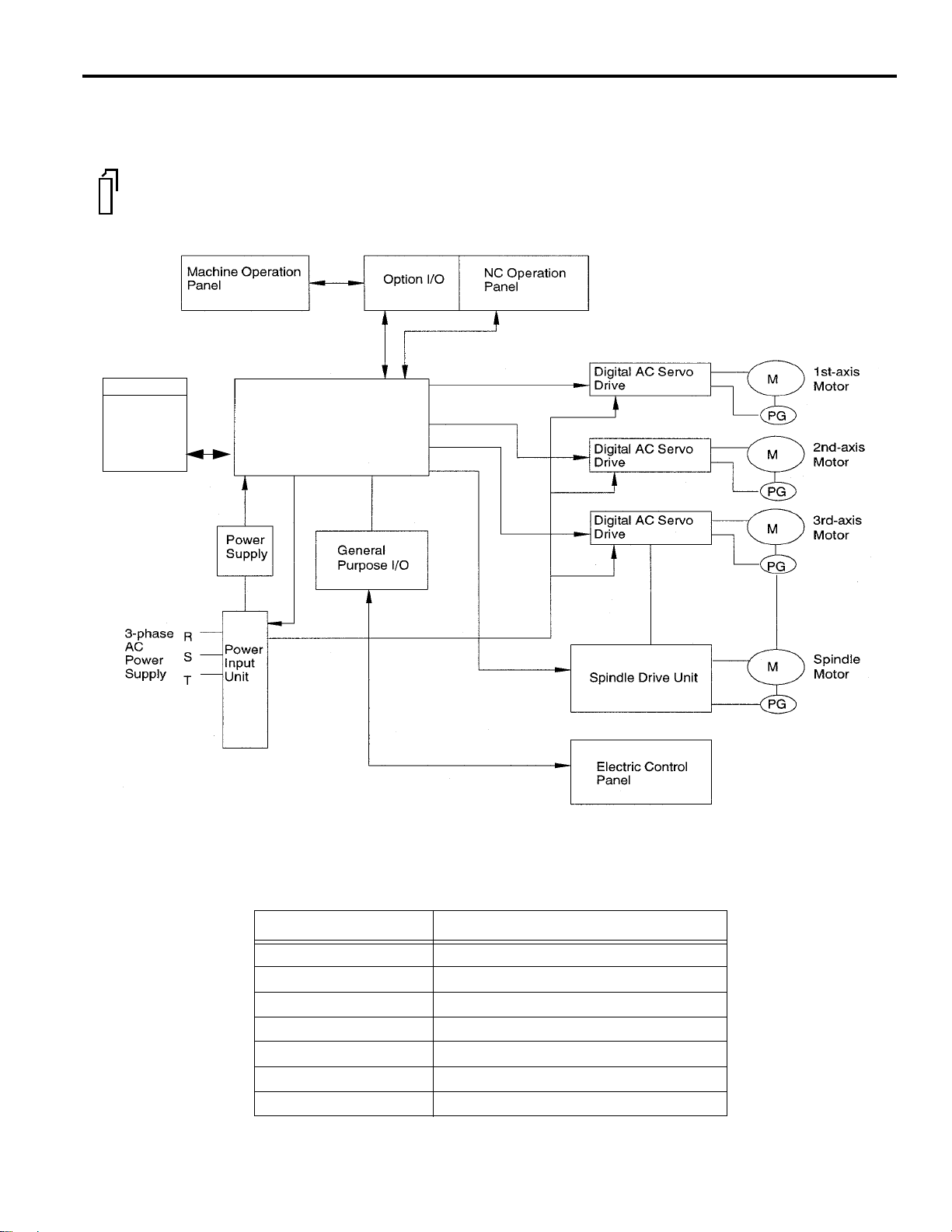
1.1 Outline of the YASNAC System
1.1.1 System Configuration
PC NC
Remote
Machine
Pendant
The configuration of the YASNAC PC NC system and the list of components are described
below.
Unit
YASNAC PC NC
Unit
Fig. 1.1.1.1 Standard Configuration of PC NC System
Table 1.1.1.1 List of YASNAC PC NC System Components
COMPONENT NAME MODEL NAME
CPU rack JZNC-JPCRKM---
NC Operation Panel JZNC-JPCOP--
SERVOPACK SGDC-
Spindle drive CIMR-M5
Servomotor SGM-
Spindle motor UAASKA-
Remote Pendant TBA
1 - 2
Page 12

YASNAC PC NC Operating Manual Chapter 1: Outline of the YASNAC System
1.1.2 Environmental Requirements
Requirements for the installation of an PC NC unit are indicated below. Install the PC NC unit in
a location where only these requirements are satisfied to avoid possible malfunctioning.
CAUTION!
Avoid using it in an environment where it may be subject to high temperatures, high humidity, dust,
corrosive gases, vibration or physical impacts that may cause fire, electric shock or malfunction.
• Use the product in an environment meeting the following conditions:
• Free from gases or vapors that create a potentially explosive atmosphere.
• Free from oil, organic solvents, etc.
• Relative humidity in the range 10 to 90% RH, with no condensation.
• Ambient temperature in the 0°C to 55°C with no freezing.
(Installation site must not be exposed to direct sunlight, must be distanced from heat generating devices,
and must be indoors.)
• Vibration not exceeding 4.9 m/s
2
.
• Do not store the product in locations subject to rain, water droplets, harmful gases or liquids.
Failure to observe this caution may result in product failure.
• Select a storage area indoors that is clean and meets the following temperature and humidity
requirements.
Ambient temperature: –15° C to 65° C (–5° F to 149° F)
Relative humidity: 10% to 90%
Failure to observe this caution may result in product failure.
(1) Ambient Temperature
For operation: 0°C to 55°C
For storage and transportation: –15° C to 65° C
Install the PC NC unit in a location not subject to direct sunlight, distant from heat sources,
and indoors.
(2) Humidity
Relative humidity must be in the range of 10 to 90%RH (non-condensing).
(3) Vibration
During operation: Max. 4.9 m/s
2
1 - 3
Page 13
YASNAC PC NC Operating Manual Chapter 1: Outline of the YASNAC System
(4) Atmosphere
Avoid the following locations:
• Dusty places
• Places where concentration of coolant and/or organic solvent mist is extremely high.
(5) Power Source
Input voltage: AC (single-phase) 180V ~ 264V
Frequency: 50/60 Hz –2 to +2 Hz
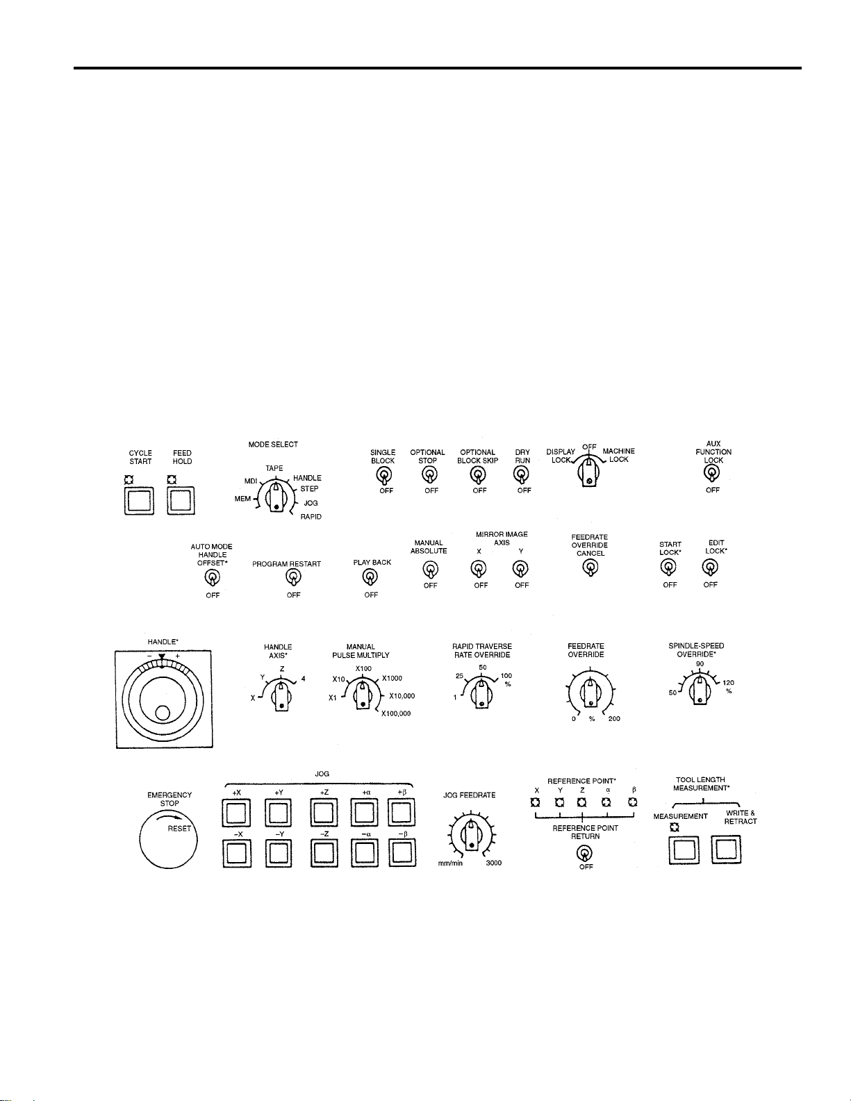
1.1.3 Machine Operation Panel
An example of the machine operation panel is indicated below. Arrangement and names of
switches and indicator lamps vary according to the machine model. For details, refer to the
machine tool manual.
Fig. 1.1.3.1 Example of Machine Operation Panel
1 - 4
Page 14

YASNAC PC NC Operating Manual Chapter 1: Outline of the YASNAC System
1.1.4 General Specifications
(1) Standard Specifications
CATEGOR ITEM AND FUNCTION
Controlled
axes
Input
command
Interpolation Positioning
Feed Rapid traverse
Storage and
editing of
program
Operation
and
display
Input/Output
function
Number of simultaneously controlled axes
Maximum programmable value
Absolute/incremental programming
Automatic acceleration and deceleration
Controlled axes
Least input increment
Least output increment
Decimal point input
Input unit 10 times
Tape code
NC tape
Input format
Buffer register
Linear interpolation
Circular interpolation
Cutting feed
Dwell
Incremental feed
Program storage capacity
Number of programs
Program editing
Program number search
Sequence number search
Address search
MDI editing
Operation panel
MDI function
l-line MDI
Operation and display
Calendar display
Pop-up me nu
Buzzer function
Input/Output interface
OPERATION
MANUAL
PROGRAMMING
MANUAL
SECTION
NO.
1 - 5
Page 15

YASNAC PC NC Operating Manual Chapter 1: Outline of the YASNAC System
CATEGOR ITEM AND FUNCTION
Tool offset Tool function
Miscellaneous function
Tool length offset
Tool pos ition offset
Number of tool offset data sets
Coordinate
system
Operation
support
function
Programming
support
function
Safety and
maintenance
Environment
requirements
Manual return to reference point
Automatic return to reference point
Automatic return to second reference point
Reference point return check
Return from reference point
Base coordinate system setting
Label skip
Single block
Optional stop
Optional block skip
Dry run
Machine lock
Miscellaneous function lock
Display lock
Manual absolute
Numerical value set-up
Break-point functio n
Operation mode
Feed hold
Circular interpolation by R command
Repetitive circle interpolation
Subprogram
Exact stop check
Exact stop check mode
Emergency stop inpu t
Overtravel
Axis interlock
Stored stroke limit
Self-diagnostics (always displayed)
Power supply
Ambient temperature
Humidity
OPERATION
MANUAL
PROGRAMMING
MANUAL
SECTION
NO.
1 - 6
Page 16

YASNAC PC NC Operating Manual Chapter 1: Outline of the YASNAC System
(2) Option Specifications
CATEGOR ITEM AND FUNCTION
Controlled
axes
Input
command
Interpolation Helical interpolation
Feed Synchronized feed (solid tap)
Storage and
editing of
program
Operation
and display
Input/output
function and
device
Spindle, tool
and miscellaneous functions
Tool offset Tool radius offset
Coordinate
system
Operation
support
function
Least input/output increment of rotary axis
Expanded number of workpiece coordinate
Automatic tool length measurement (TLM)
Number of controlled axes
Rotary axis control
Inch/metric switching
Multi-active registers
High-speed mode operation
F1-digit
Simultaneous1-axis handle feed
Simultaneous 2-axis handle feed
Simultaneous 3-axis handle feed
Addition of program storage capacity
Addition of number of programs
Playback
Internal toggle switch
NC program drawing
Comment display function
Tape reader without take-up reels
Tape reader with take-up reels
RS-232C interface
T4-digit command
Second miscellaneous function
Addition of tool offset data sets
Manual second reference point return
Automatic third/fourth reference point
return
Workpiece coordinate system setting
systems
Local coordinate system
Rotation of workpiece coordinate system
Optional block skip B
Automatic mode handle offset
Program restart
Manual interruption point return
OPERATION
MANUAL
PROGRAMMING
MANUAL
SECTION
NO.
1 - 7
Page 17

YASNAC PC NC Operating Manual Chapter 1: Outline of the YASNAC System
CATEGOR ITEM AND FUNCTION
Programming
support
function
Accuracy
correction for
mechanical
system
Automation
support
function
Safety and
maintenance
Hole machining pattern cycle
Stored pitch error compens ation
Canned cycle
Canned cycle B
Circle cutting
Macroprogram
Programmable mirror image
Scaling
Coordinate system rotation
Automatic comer override
Programmab le data input
Program copy
Unidirectional approach
Skip function
Tool life control function
Program interruption
Stored stroke limit B
Stored stroke limit C
OPERATION
MANUAL
PROGRAMMING
MANUAL
SECTION
NO.
1 - 8
Page 18

YASNAC PC NC Operating Manual Chapter 1: Outline of the YASNAC System
1.2 Protective Functions
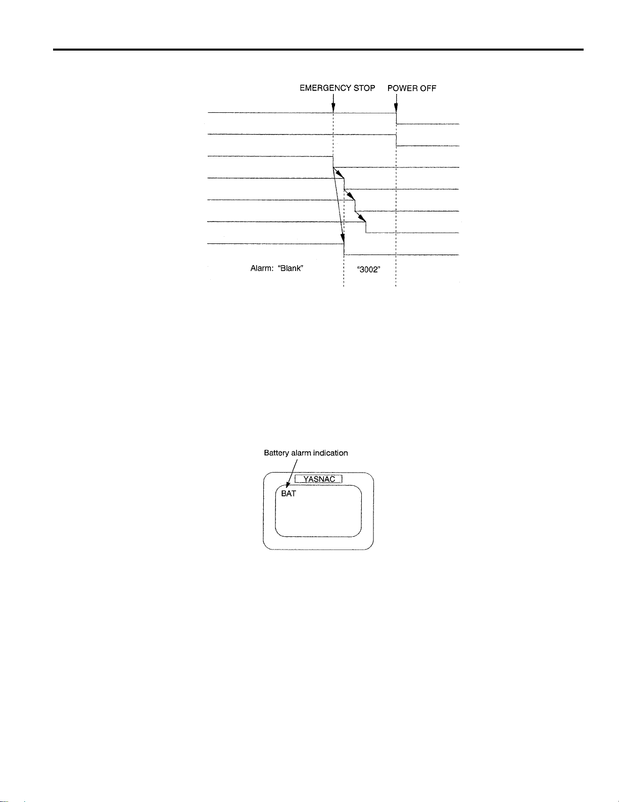
1.2.1 Emergency Stop
Press the emergency stop button immediately if a problem occurs with the system or line. The
execution of all commands stops instantaneously when the emergency stop button is pressed.
Servo power supply of the PC NC is shut OFF and dynamic brake is applied to stop all mechanical movement. In the emergency stop state, the PC NC is in the alarm state “3002”. If the emergency stop signal is “opened”, the PC NC stops the entire operation, and the SVMX and BKX
signals are “opened”.
PC NC
This operation is executed by setting the pins on the board. The pins di ffer between J300M
and J100M.
Table 1.2.1.1 Emergency Related Signals
1.2.2 Overtravel
The overtravel function stops axis feed operation when an axis reaches the travel limit; for the
detection of travel limit, a limit switch and a dog are used and if an axis reaches the travel limit,
the limit switch outputs a signal and the function stops axis feed operation in response to this
input. The axis reached and stopped at the travel limit can be moved manually into the axis movable range.
When the overtravel input is “opened”, axis movement is stopped in the manner as indicated in
Table 1.2.2.1. In response to this input, the alarm output (ALM) is “closed” and the corresponding alarm message is displayed on the screen.
Signal Name Pin Setting
Emergency Stop Input CN12-19 pin on JZNC-JFC 10 board
SVMX CN12-17 pin on JZNC-JFC 10 board
BKX CN12-16 pin on JZNC-JFC 10 board
Table 1.2.2.1 Axis Stop Direction with Overtravel Input “Opened”
Manual Operation Mode Automatic Operation Mode
*+X to *+5
input is “opened”
*-X to *-5
input is “opened”
* Normally closed contact
Movement in the *+X to *+5
direction is stopped.
Movement in the *-X to *-5
direction is stopped.
1 - 9
Movement of all axes is
stopped in all directions.
Page 19
YASNAC PC NC Operating Manual Chapter 1: Outline of the YASNAC System
If the overtravel input is “opened”, select the manual mode (jog, pulse handle) and move the axis
in the direction opposite to the direction for which the overtravel input is “opened” to “close” the
input. After that press the [RESET] key on the NC operation panel, the alarm output and display
are canceled.
1. After the occurrence of an alarm due to the “open” of the overtravel input, the M, S, and
T code read output signals (MF, SF and TF) are not turned OFF.
2. If it is necessary to interrupt the operation called by M, S and/or T code, set the interlock
by an external sequence.
3. The alarm numbers at the occurrence of overtravel are 2001 to 2005. If the overtravel
alarm occurs, axis move is stopped. Note that the servo is not turned OFF.1
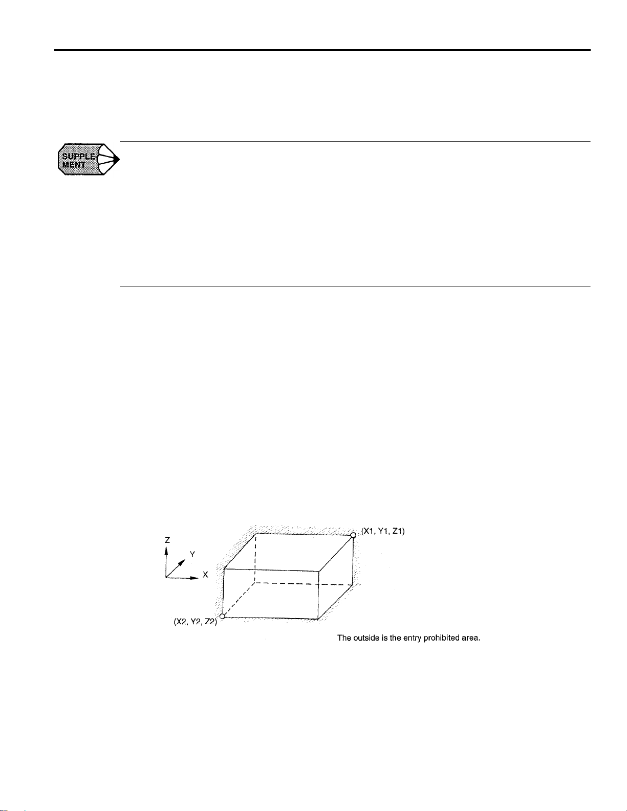
1.2.3 Stored Stroke Limit
To ensure improved safety in operation, this function prevents axis from entering the preset entry
prohibited areas both in manual and automatic operation.
(1) Stored Stroke Limit
To use the stored stroke limit function, the axis movable area is set by parameters with the
coordinate values in the machine coordinate system. The area outside the set boundary is
established as the entry prohibited area. If an axis enters the entry prohibited area, the function
stops axis movement and displays an alarm message. The function is made valid upon completion of the manual reference point return after the power is turned ON. In automatic operation, if even one axis causes the alarm, all axis are stopped.
In manual operation, only the axis that caused an alarm is stopped.
Fig. 1.2.3.1 Stored Stroke Limit
1 - 10
Page 20
YASNAC PC NC Operating Manual Chapter 1: Outline of the YASNAC System
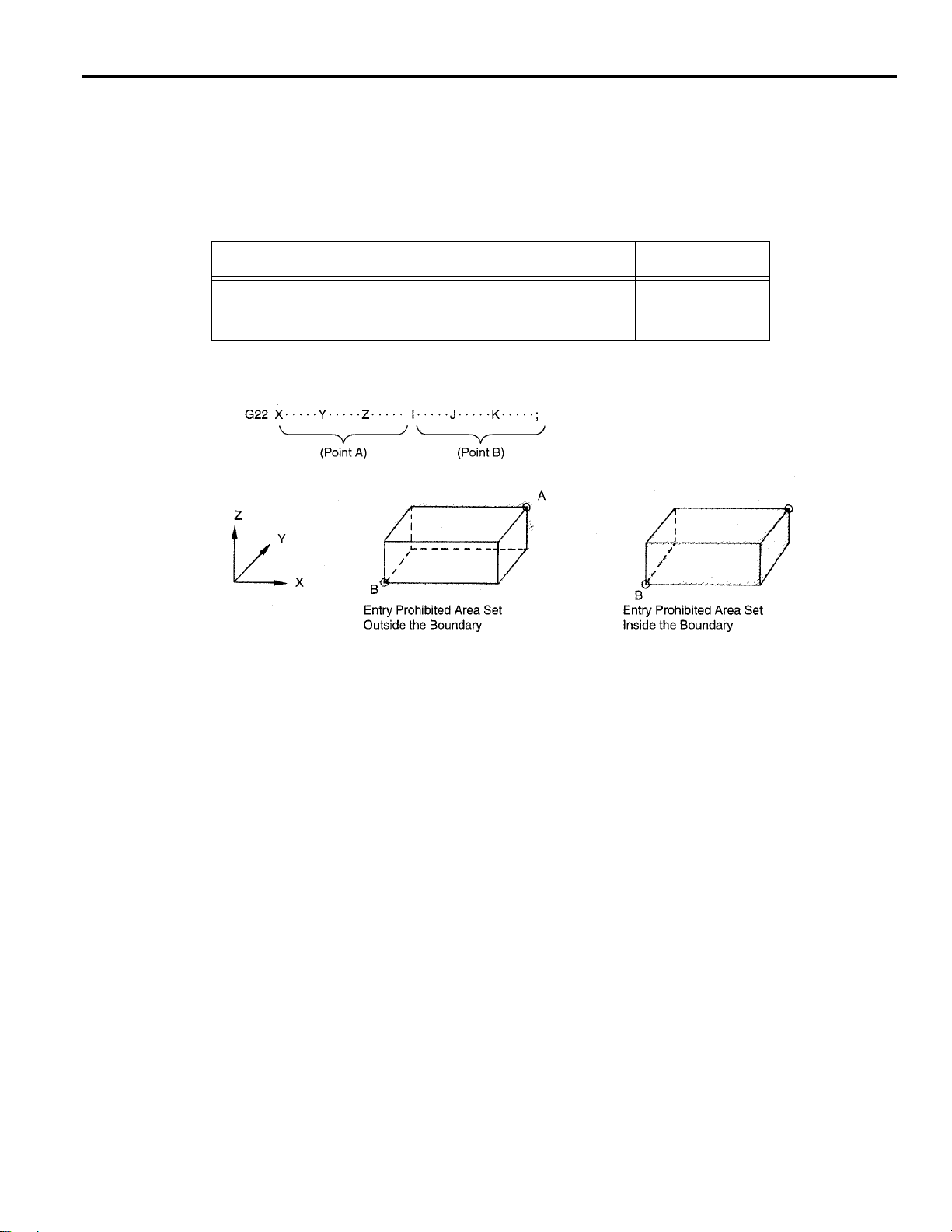
(2) Stored Stroke Limit B, C (G22, G23) *
The area either outside or inside the boundary set by parameters or by the commands in a
program is established as the entry prohibited area. The boundary is set with the coordinate
values in the machine coordinate system. Whether the entry prohibited area is established outside or inside the boundary can be determined by the setting for a parameter. The function is
made valid upon completion of the reference point return after turning ON the power.
G CODE FUNCTION GROUP
G22 Turning ON the stored stroke limit B 04
G23 Turning OFF the st ored stroke l i mit B 04
Fig. 1.2.3.2 Stored Stroke Limit B Function
• In addition to the stored stroke limits A and B, stored stroke limit C can be added.
• With the stored stroke limit C, set the boundary of the area and inside or outside the
boundary by parameters.
• According to the setting for the parameter or the input signal, one of the stored stroke limit
C (third to fifth prohibited area) can be made valid.
• For details of the stored stroke limit B, C, refer to 4.2.3 “Stored Stroke Limit B and C
(G22, G23)” in the PROGRAMMING MANUAL.
1 - 11
Page 21

YASNAC PC NC Operating Manual Chapter 1: Outline of the YASNAC System
1.2.4 Interlock Inputs
The interlock input is the signal used to disable axis movement, and is provided for each axis.
• When an axis is interlocked during movement, it is stopped after deceleration.
• When the interlock is released, the axis continues moving to comple te the r emainin g commands. Upon completion of the commands, the program advances to the next block.
• For simultaneous two or three axis interpolation commands, interpolation operation is disabled if one of these two or three axis is interlocked.
Fig. 1.2.4.1 Interlock Inputs
1 - 12
Page 22

YASNAC PC NC Operating Manual Chapter 2: PC NC System Outline
2
PC NC System Outline
Chapter 2 describes various operations including power ON procedure,
manual operation and automatic operation.
2.1 General Operation Flow . . . . . . . . . . . . . . . . . . . . . . . . . . . . . . . . . . . . . . . . . . . 2-2
2.2 Inspection Before Turning the Power ON . . . . . . . . . . . . . . . . . . . . . . . . . . . . . 2-3
2.2.1 Inspection of the NC Unit . . . . . . . . . . . . . . . . . . . . . . . . . . . . . . . . . . . 2-4
2.2.2 Preparation before Turning the Power ON. . . . . . . . . . . . . . . . . . . . . . . 2- 5
2.3 Turning the Power ON and Inspecting After Power ON . . . . . . . . . . . . . . . . . . 2-6
2.3.1 Procedure for Turning the Power ON . . . . . . . . . . . . . . . . . . . . . . . . . . 2-6
2.3.2 Checking the Motors for Abnormalities . . . . . . . . . . . . . . . . . . . . . . . . 2-7
2.3.3 Procedure for Turning Power OFF . . . . . . . . . . . . . . . . . . . . . . . . . . . . 2-7
2.3.4 Inspection of the Battery . . . . . . . . . . . . . . . . . . . . . . . . . . . . . . . . . . . . 2-8
2.4 Manual Operation (1) . . . . . . . . . . . . . . . . . . . . . . . . . . . . . . . . . . . . . . . . . . . . 2-11
2.4.1 Manual Rapid Traverse (RAPID) . . . . . . . . . . . . . . . . . . . . . . . . . . . . 2-11
2.4.2 Jog Feed (JOG) . . . . . . . . . . . . . . . . . . . . . . . . . . . . . . . . . . . . . . . . . . 2-11
2.4.3 Step Feed (STEP) . . . . . . . . . . . . . . . . . . . . . . . . . . . . . . . . . . . . . . . . . 2-12
2.4.4 Handle Feed (HANDLE)* . . . . . . . . . . . . . . . . . . . . . . . . . . . . . . . . . . 2-12
2.5 Manual Operation (2) . . . . . . . . . . . . . . . . . . . . . . . . . . . . . . . . . . . . . . . . . . . . 2-13
2.5.1 Simultaneous 2 or 3-axis Handle Feed * . . . . . . . . . . . . . . . . . . . . . . . 2-13
2.5.2 Manual Reference Point Return . . . . . . . . . . . . . . . . . . . . . . . . . . . . . . 2-14
2.5.3 Manual Reference Point Return to the Second Reference Point* . . . . 2-16
2.5.4 1-line MDI . . . . . . . . . . . . . . . . . . . . . . . . . . . . . . . . . . . . . . . . . . . . . . 2-17
2.6 Automatic Operation (1) . . . . . . . . . . . . . . . . . . . . . . . . . . . . . . . . . . . . . . . . . 2-18
2.6.1 Preparation of Automatic Operation . . . . . . . . . . . . . . . . . . . . . . . . . . 2-18
2 - 1
Page 23

YASNAC PC NC Operating Manual Chapter 2: PC NC System Outline
2.6.2 MDI Operation . . . . . . . . . . . . . . . . . . . . . . . . . . . . . . . . . . . . . . . . . . . 2-21
2.6.3 Feed Hold . . . . . . . . . . . . . . . . . . . . . . . . . . . . . . . . . . . . . . . . . . . . . . . 2-21
2.6.4 Override . . . . . . . . . . . . . . . . . . . . . . . . . . . . . . . . . . . . . . . . . . . . . . . . 2-21
2.7 Automatic Operation (2) . . . . . . . . . . . . . . . . . . . . . . . . . . . . . . . . . . . . . . . . . 2-23
2.7.1 Optional Stop . . . . . . . . . . . . . . . . . . . . . . . . . . . . . . . . . . . . . . . . . . . . 2-23
2.7.2 Optional Block Skip . . . . . . . . . . . . . . . . . . . . . . . . . . . . . . . . . . . . . . . 2-23
2.7.3 Dry Run . . . . . . . . . . . . . . . . . . . . . . . . . . . . . . . . . . . . . . . . . . . . . . . . 2-24
2.7.4 Display Lock and Machine Lock . . . . . . . . . . . . . . . . . . . . . . . . . . . . . 2-24
2.7.5 Auxiliary Function Lock . . . . . . . . . . . . . . . . . . . . . . . . . . . . . . . . . . . 2-25
2.7.6 Z-axis Command Neglect . . . . . . . . . . . . . . . . . . . . . . . . . . . . . . . . . . 2-25
2.7.7 4th-axis Command Neglect . . . . . . . . . . . . . . . . . . . . . . . . . . . . . . . . . 2-25
2.7.8 5th-axis Command Neglect . . . . . . . . . . . . . . . . . . . . . . . . . . . . . . . . . 2-26
2.8 Operation Intervention During Automatic Operation . . . . . . . . . . . . . . . . . . . 2-27
2.8.1 MDI Operation Intervention during Automatic Operation . . . . . . . . . 2-28
2.8.2 Automatic Handle Mode Offset * . . . . . . . . . . . . . . . . . . . . . . . . . . . . 2-28
2.8.3 Manual Absolute . . . . . . . . . . . . . . . . . . . . . . . . . . . . . . . . . . . . . . . . . 2-30
2 - 2
Page 24
YASNAC PC NC Operating Manual Chapter 2: PC NC System Outline
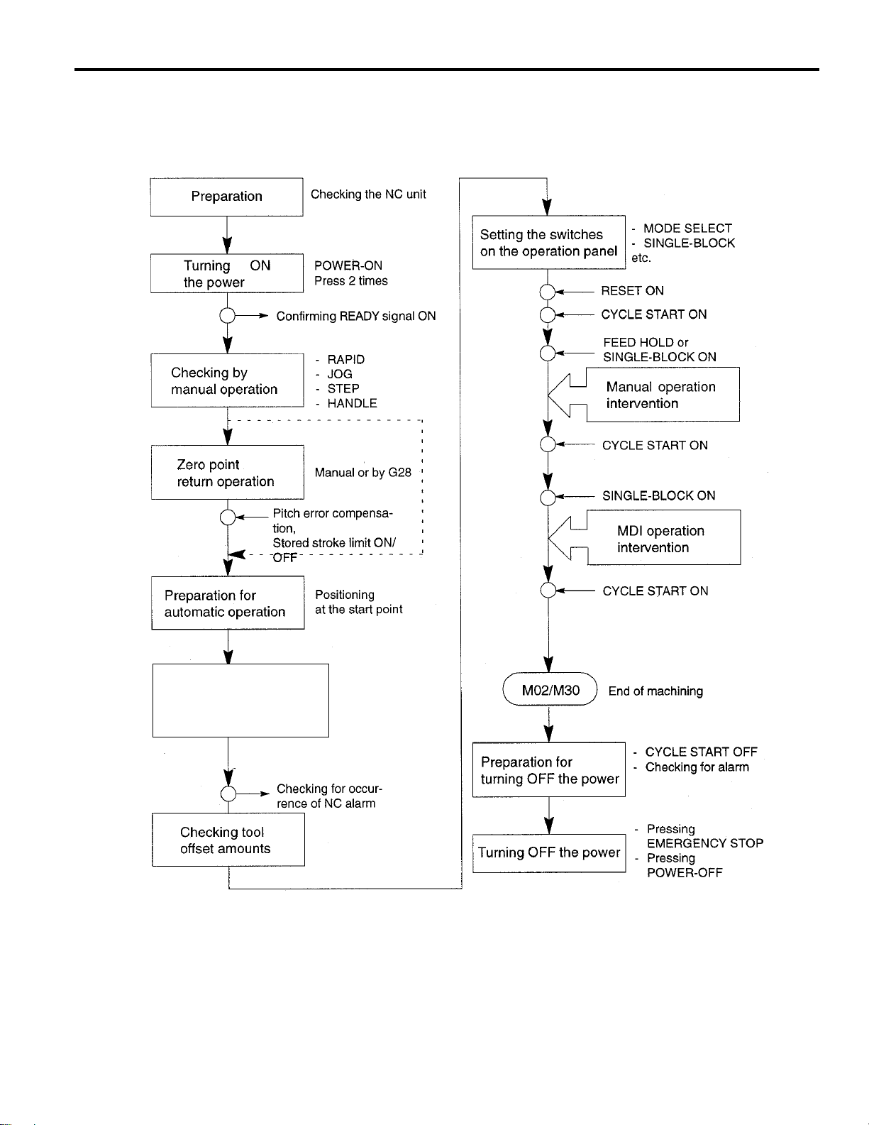
2.1 General Operation Flow
The operation procedure usually followed for daily operation is indicated in Fig.2.1.1. This chapter explains these operation items.
Setting Part Program
Loading NC program from PC
by Etherne t or from touch
screen and executing the
Program numbers
Fig. 2.1.1 Operation Procedure
2 - 3
Page 25

YASNAC PC NC Operating Manual Chapter 2: PC NC System Outline
2.2 Inspection Before Turning the Power ON
Before turning the power ON for YASNAC PC NC, it is necessary to carry out inspection to
Ensure safety. If the power is turned ON while the system has trouble, it could cause malfunctioning of the system itself and create a hazards conditions for the operations. Make sure to carryout daily inspection before turning the power ON.
WARNING!
• Always turn all power OFF (including the primary power supply) before carrying out daily
inspection.
Performing the inspection with the power ON may lead to electric shock.
• Wait 5 minutes after turning the power (including the primary power supply) OFF before
removing or replacing any unit or part.
• Failure to observe this warning could lead to electric shock and equipment failure.
• Do not touch any unit, terminals, etc., while the power is ON.
Failure to observe this war ning could lead to electric shock or device malfunction.
• Immediately after switching the power OFF, the product retains some electric charge. Do not
touch any parts (which are live when the power is ON) for 5 minutes after switching the power
OFF.
Failure to observe this war ning could lead to electric shock or device malfunction.
• Do not damage cables, subject them to excessive stress, or pinch them.
Excessive load on cables may cause electric shock.
• When the equipment is powered ON, never touch its rotating parts.
Failure to observe this warning could result in personal injury.
• Never modify the product.
2 - 4
Page 26

YASNAC PC NC Operating Manual Chapter 2: PC NC System Outline
CAUTION!
• To prevent personnel other than those involved in maintenance and inspection work from
turning the power ON while maintenance and inspection is in progress, place signs stating
“DO NOT TURN THE POWER ON” or words to that effect at the primary power
supplies of related control panels and other relevant locations.
Failure to observe this caution could lead to electric shock.
• Electronic devices such as CMOS ICs are used on the control boards. If you touch the IC’s
with your bare fingers, static electrical charge in your body could destroy these IC’ s, care must
be taken when handling these devices. Before handling these devices for maintenance purposes,
first discharge the static electricity in your body by touching a grounded metal device.
Failure to observe this caution could lead to personal injury and product failure.
• Do not install or remove boards, wiring, connectors, etc., while the power is ON.
Failure to observe this caution could lead to electric shock, product failure, and malfunction.
• Do not let foreign matter such as electrical wire scrap enter the unit.
Failure to observe this caution could result in fire, product failure or malfunction.
• Be sure to check the following points after completing maintenance and inspection work:
• Check that all fastening bolts are tightened.
• Check that no tools or other objects have been left inside the control panel.
• Check that the control panel door is closed properly.
Failure to carry out these checks could lead to electric shock, injuries, fire, and malfunction.
• Never attempt to disassemble the NC unit modify units/devices inside the PC NC unit.
Failure to observe this caution could lead to fire, product failure and malfunction.
• Do not change the set values of the devices, variable resistors, etc., in the control panel.
Failure to observe this caution could lead to fire, product failure, and malfunction.
2.2.1 Inspection of the NC Unit
In this subsection, the items to be inspected before turning ON the power are indicated for the
standard PC NC box supplied by Yaskawa. For the machine tool’s control box, refer to the
machine tool manuals.
(1) Inspecting the Machine Cabinet Doors
Make sure that the doors are securely closed before turning the power ON. The PC NC CPU
rack is not protected against oil mists or other airborne foreign matter. The door of the
machine cabinet doors must always be kept closed before powering ON.
2 - 5
Page 27

YASNAC PC NC Operating Manual Chapter 2: PC NC System Outline
(2) Inspecting the Shielding Parts in the Machine Cabinet
Inspect the shielding parts in the Machine Cabinet every month for gaps and/or damage.
Open the doors and check the packings installed around the door for damage.
Inspect the inside of the Machine Cabinet for abnormal contamination. If the inside is
abnormally dirty, clean it immediately after locating the cause of contamination.
Lock the doors securely and inspect the doors to make sure that there are no gaps.
By carrying out the inspection procedures indicated above at regular intervals, the YASNAC
PC NC can perform efficiently for a long time.
2.2.2 Preparation before Turning the Power ON
Before turning the power ON, confirm the following conditions:
• Make sure that the front side of the PC NC unit is closed. If the door is open or if there is a gap
between the door and the box panels, securely close and lock the door.
• Carry out the inspection for the machine and machine related controllers according to the
instructions in the machine tool manuals.
2 - 6
Page 28

YASNAC PC NC Operating Manual Chapter 2: PC NC System Outline
2.3 Turning the Power ON and Inspecting After Power ON
In this section, the procedure to be used for turning the power ON is explained. Inspection that
must be conducted after turning the power ON is also described.
WARNING!
• Be sure to turn the power OFF before replacing the battery.
Failure to observe this warning could lead to electric shock and product failure.
CAUTION!
• Replace fuses and batteries with the recommended products.
Failure to observe this caution could result in fire or product failure.
• Use the product with the “System Number Switch” of the CPU set to “0”.
Using while set to another number could lead to malfunction.
• Wait at least 2 seconds after turning the power OFF before turning it ON again.
Failure to observe this caution could lead to malfunction.
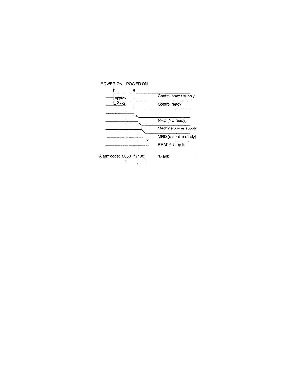
2.3.1 Procedure for Turning the Power ON
Turn the power ON in the following sequence.
Make sure that the power supplied to the PC NC unit is from an external power source.
Press the POWER ON button on the NC operation panel. Control power is turned ON and t he
cooling fan starts rotating.
Make sure that air is flowing out at the upper part on the side of the NC unit.
• In approximately 20 seconds, the control is ready for turning ON the servo power (alarm
code 3000).
Press the POWER ON button again - one time.
• The servo power is turned ON. When the machine is ready for operation, the NC enters
the ready state.
• When the power is correctly turned ON to the NC unit, the NRD (NC ready) signal is output.
• When the power is turned ON at the machine side in response to the NRD signal, the
MRD (machine ready) signal will be returned to the NC. The READY lamp goes on when
the MRD signal is returned. Note that a READY lamp is not used with some types of
machines.
2 - 7
Page 29
YASNAC PC NC Operating Manual Chapter 2: PC NC System Outline
• When the NC unit enters the ready state, the alarm message (displayed on the screen) will
go off.
If the NC unit fails to enter the ready state, locate the cause by referring to Section 7.2,
“ALARM DISPLAY JOB”, and take appropriate steps. For turning the power ON, there are
items that must be inspected at the machine side in addition to the NC unit related items. For
the former items, refer to the machine tool manuals.
5
PC NC Boots MMI screens
Fig. 2.3.1.1 Power ON Sequence
2.3.2 Checking the Motors for Abnormalities
Check the operation of the motors running. If abnormal vibration or noise occurs, turn the power
OFF and contact the maintenance personnel.
2.3.3 Procedure for Turning Power OFF
Turn the power OFF in the following sequence:
Make sure that the CYCLE START lamp on the machine operation panel is OFF with the
machine stopped.
Make sure that there is no alarm message displayed on the CRT screen. If an alarm message is
displayed, locate the cause by referring to Chapter 4, “MAINTENANACE” and take appropriate measures to clear it.
Carry out necessary STEPS for turning the power OFF at the machine side. For details, refer
to the machine tool manuals.
Press the EMERGENCY STOP button on the machine operation panel to turn the servo
power OFF.Press SHUTDOWN button to close all opened windows of PC NC.
When the safe SHUTDOWN message is displayed on CR T, Press the POWER OFF button on
the NC operation panel to shut off the power to PC NC.
2 - 8
Page 30
YASNAC PC NC Operating Manual Chapter 2: PC NC System Outline
Turn the power supply to the NC OFF by turning OFF a circuit breaker, etc.
PC NC Control Power Supp ly
PC NC Display
Shut Down button
Shut Down of PC Side
Closing Windows NT
Safe to Turn Off Windows NT
Fig. 2.3.3.1 Power OFF Sequence
2.3.4 Inspection of the Battery
After turning the power ON, if there is a battery alarm, a br oken battery icon will be displayed, or
a solid battery is displayed to indicate everything is normal. After two minutes this normal battery indicator will disappear. When battery alarm is displayed by red battery icon, the battery
must be replaced immediately. Standard batteries cannot be used. For a replacement of battery,
contact your Yaskawa representative for Battery type: ER6VC3, Parts code: BA510
(1) Checking the Battery Which Needs Replacing
Follow the procedure indicated below to determine whether or not battery must be
replaced.
Press the POWER OFF button.
If a door interlock switch is installed, place the door interlock key in the OFF position.
This makes a power ON condition possible with the door opened.
Open the door so that the front part of the PC NC unit is visible.
Press the POWER ON button again - once.
2 - 9
Page 31

YASNAC PC NC Operating Manual Chapter 2: PC NC System Outline
Check the red color LED on the JANCD-JFC10 board. If it is lit, the battery must be
replaced.
Fuse (HM03, 0.3A)(F1)
I/O module power output
verification LED
I/O module power output
verification LED
Battery power supply
connector (CN06)
Battery
Fuse (5A) (F2)
(Behind Battery)
LITHIUM
Fig. 2.3.4.1 Location of the Battery on the PC NC board
2 - 10
Page 32

YASNAC PC NC Operating Manual Chapter 2: PC NC System Outline
(2) Replacing the Battery
Replace the battery easily with the following procedure.
Turn the PC NC power OFF.
Remove connector of Battery.Then, remove the battery from the holder by removing the
solder.
Fit the new battery in the holder and caref ully sold er RED( +) and BLACK ( -) wire s to the
Battery. Put the battery in its holder. Then put back battery connector, the connector may
be inserted in either direction, it must be securely inserted, otherwise, the power will not
be supplied by the battery. (See Fig. 2.7.)
Connect Red wire
( + )
B
A
T
T
E
R
Y
Connect Black wire ( - )
Fig. 2.3.4.2 Connecting the Battery Connector
Turn the power ON.
Make sure that “BAT” is not blinking on the CRT screen, and that the red color LED in
the board is OFF.
Note 1: Table/FigNote1
1. If the red color LED remains lit after replacing the battery, the connector might be inserted
incorrectly or the battery might be faulty.
2. Power OFF operation is allowed a few seconds after turning the power ON.
3. After turning the power OFF, replace the battery quickly. If the PC NC unit is left with the
battery removed, the data stored in the memory could be lost.
2 - 11
Page 33

YASNAC PC NC Operating Manual Chapter 2: PC NC System Outline
2.4 Manual Operation (1)
This section describes generally the manual operation. To move an axis manually, select the
operation mode of RAPID, JOG, STEP, or HANDLE with the MODE SELECT switch on
the machine operation panel.
2.4.1 Manual Rapid Traverse (RAPID)
An axis can be moved at a rapid traverse rate. Follow the procedure indicated below.
Select the rapid mode by placing the MODE SELECT switch on the machine operation panel
in the RAPID position.
Select the feedrate to be used for axis feed operation by the RAPID TRAVERSE and RATE
OVERRIDE switch on the machine operation panel.
• Override setting is possible in four steps of 100%, 50%, 25%, and F0. The feedrate corresponding to the setting at 100%, 50%, and 25% is set for parameters pm2801 to pm2805.
For the setting at F0, feedrate set for parameter pm2447 is used.
• Optionally, F1 and F2 positions are selectable. Feedrate to be selected according to the
switch setting at F1 and F2 is set for parameters pm2448 and pm2449.
On the machine operation panel, press the JOG button that corresponds to the axis and the
direction in which the axis should move. The axis moves at a rapid traverse rate while t he button is held pressed.
2.4.2 Jog Feed (JOG)
It is possible to move an axis in the jog feed mode. Follow the procedure indicated below.
Select the jog mode by placing the MODE SELECT switch on the machine operation panel in
the JOG position.
Select the feedrate with the JOG FEEDRATE switch on the machine operation panel.
2 - 12
Page 34

YASNAC PC NC Operating Manual Chapter 2: PC NC System Outline
• Feedrate can be selected from 32 steps, with actual feedrates of individual setting positions set for parameters pm2400 to pm2431. The actual number of steps and feedrates
selectable by the JOG FEEDRATE switch vary depending on the machine model. For
details, refer to the manuals published by the machine tool builder.
Press the JOG switch corresponding to the axis to be moved and the required axis move direc-
tion.
The axis moves at the selected feedrate while the JOG switch is held pressed.
2.4.3 Step Feed (STEP)
Manual step feed operation is possible. Follow the procedure indicated below.
Select the step mode by placing the MODE SELECT switch on the machine operation panel
in the STEP position.
Select the feed distance per step with the MANUAL PULSE MULTIPLY switch on the
machine operation panel.
Metric system: 0.001, 0.01, 0.1, 1.0, 10.0, 100.0 mm (per step)
Inch system: 0.0001, 0.001, 0.01, 0.1, 1.0, 10.0 inch (per step)
Press the JOG switch corresponding to the axis to be moved and the required axis move direc-
tion.
Each time the JOG switch is pressed, the selected axis moves in the selected direction by the
set feed distance per step.
2.4.4 Handle Feed (HANDLE)*
When the NC is equipped with a manual pulse generator, pulse handle feed operation is possible.
Follow the procedure indicated below.
Select the handle mode by placing the MODE SELECT switch on the machine operation
panel in the HANDLE position.
Select the axis to be moved by the HANDLE AXIS selection switch on the machine operation
panel.
With the MANUAL PULSE MULTIPLY switch on the machine operation panel, select the
axis feed distance per pulse (one division of the pulse handle).
Clockwise rotation: In the positive direction
Counterclockwise direction: In the negative direction
Metric system: 0.001, 0.01, 0.1 mm (per division)
Inch system: 0.0001, 0.001, 0.01 inch (per division)
Turn the pulse handle. The axis moves in the positive or negative direction according to the
direction in which the pulse handle is turned.
2 - 13
Page 35

YASNAC PC NC Operating Manual Chapter 2: PC NC System Outline
2.5 Manual Operation (2)
This section describes manual operations carried out in daily production using the manual
operation functions explained in 2.4 “MANUAL OPERATION (1)“.
2.5.1 Simultaneous 2 or 3-axis Handle Feed *
By installing the pulse handle for the individual axis, it is possible to move up to three axis among
the X-, Y-, Z-, α-, and β-axis simultaneously. Follow the procedure indicated below.
Fig. 2.5.1.1 Simultaneous 2 or 3-axis Pulse Handle Feed
Select the handle mode by placing the MODE SELECT switch on the machine operation
panel in the HANDLE position.
Select the axis feed distance per graduation of the pulse handle with the MANUAL PULSE
MULTIPLY switch on the machine operation panel. This switch is used in common for the
three pulse handles.
Turn the pulse handle. The sel ected axis is move d in the positive or negati ve dire cti on accord-
ing to the handle turning direction.
2 - 14
Page 36

YASNAC PC NC Operating Manual Chapter 2: PC NC System Outline
2.5.2 Manual Reference Point Return
Axes can be returned to the reference point in manual operation. Follow the procedure indicated
below.
Select the rapid or jog mode by placing the MODE SELECT switch on the machine operation
panel in the RAPID or JOG position.
Move an axis manually (manual rapid traverse or jog feed) to a position away from the refer-
ence point (within the reference point return enabled area). When an axis is located in range
A in Fig. 2.5.2.1, reference point return can be executed correctly.
Turn ON the REFERENCE POINT RETURN switch.
Keep the JOG switch pressed corresponding to the axis returning to the reference point and in
the return direction. When the JOG switch is held pressed, the corresponding axis starts moving in the same manner as ordinary manual axis feed operation.When the axis reaches the
deceleration point, feedrate is decelerated to a low feedrate and the axis stops automatically
at the reference point.
Upon completion of the reference point return, the REFERENCE POINT lamp of that axis
lights.
Fig. 2.5.2.1 Manual Reference Point Return
Reference Point is a specific position in the machine coordinate system. It is also called
the machine zero point or the machine reference point.
2 - 15
Page 37

YASNAC PC NC Operating Manual Chapter 2: PC NC System Outline
1. Once the reference point return is completed, point C indicated in Fig. 2.5.2.1 is stored to
the NC. Therefore, if reference point return is attempted while an axis is in area B, an error
occurs. In this case, the axis should first be returned to area A and then the reference point
return should be executed.
2. The axis for which the reference point return has been completed can be moved in
the reference point return direction manually only if the reference point return switch
is turned OFF.
3. If commands have been read to the buffer area during automatic operation, manual
reference point return must not be executed. If manual return operation is executed,
the data in the buffer area is cleared.
1. Immediately after the power is turned ON, the axis start manual or automatic reference
point return operation independent of the present axis position. However, reference point
return cannot be executed correctly if the axis is located in area B. In this case, the axis
must be returned to area A before executing reference point return.
2. If the MODE SELECT switch setting is changed while an axis is moving automatically to
the reference point, an alarm (alarm 2141 to 2145 reference point return interruption error)
occurs.
3. Reference point return cannot be executed when the MACHINE LOCK switch is ON.
4. With a rotary axis, it is possible to execute automatic reference point return as with a
linear axis.With a rotary axis, if it has been moved by more than ± 360.000° from the
reference point established first, reference point return is executed to the closest reference
point in the preset direction of reference point return.
The illustration below shows how the reference point return is executed from points A and
B. (The reference point return direction is determined by the setting for pm4002 D3 and
D4.)
5. Once the reference point return is completed, second and later reference point return is
executed at a high-speed mode. This is called “high-speed reference point return”. However, if the setting is so made to execute the reference point return at a low speed (pm4003
D6 = 1), second and later reference point return is executed at a low speed.
2 - 16
Page 38

YASNAC PC NC Operating Manual Chapter 2: PC NC System Outline
2.5.3 Manual Reference Point Return to the Second Reference Point*
The axis are automatically positioned at the second reference point. This operation allows positioning at the second reference point independent of the present axis position, whether it is in
the negative side or positive side from the second reference position. Follow the procedure indicated below.
Select the jog or rapid mode by placing the MODE SELECT switch in the JOG or RAPID
position.
Turn ON the ZRN2 (second zero point return request) switch on the machine operation panel.
Keep the JOG switch corresponding to the axis and direction of reference point return. The
corresponding axis is positioned at the second zero point at the jog feedrate or rapid traverse
rate according to the selected mode.
• If the ZRN2 switch is turned OFF while an axis is moving to the second reference point,
the axis stops moving. To restart the second reference point return operation, turn ON the
ZRN2 switch and turn OFF the JOG switch having been pressed once, then press it once
again.
• If the JOG switch is pressed again to be turn ed OFF while the X-a xis is moving t o the second zero point, the axis stops moving. In this case, press the JOG switch again to turn it
ON, and the X-axis restarts moving to the second zero point.With the Y- and Z-axis, this
is also applied.
1. If the JOG switches of [+] and [–] are pressed at the same time, the corresponding axis
stops moving since this operation is assumed to have turned OFF the JOG switch.
2. It is not allowed to use the first zero point return mode and the second reference point
return mode at the same time. If both input signals are ON at the same time, both of the
modes are invalid and neither jog nor rapid feed is executed. This feature is provided to
ensure safety.
3. If the NC is in either the machine lock state (including the machine lock for individual
axis) or the Z-axis command disregard state, the second zero point return operation cannot be executed. When a JOG switch is pressed under such a state, normal jog operation
is preformed.
4. With the axis for which second zero point return has been completed, manual axis move
operation is allowed only after the ZRN2 (second reference point return) switch is turned
OFF.
2 - 17
Page 39

YASNAC PC NC Operating Manual Chapter 2: PC NC System Outline
1. If the second zero point return input signal is turned ON in the state that the first zero point
return has not been completed, the input is invalid and the second reference point return
mode cannot be set.
2. In the second reference point return mode, input from the JOG switch [-X] ([-Y], [-Z]) is
valid. If the mode is changed, the ZRN2 switch is assumed to have been turned OFF.
2.5.4 1-line MDI
During the execution of manual operation, it is possible to execute one block of a part program by
directly entering it to the CR T screen. For this type of operation, a maximum of 40 characters can
be written and the function codes that are allowed are M, S, T, F, and E codes. However, M00,
M01, M02, M30, M90 to M99, and M190 to M199 cannot be specified. An offset command with
a T command is also disregarded. With the system that carries out set-up by using a T command,
a T command must not be specified for this 1-line MDI operation. Follow the procedure indicated
below.
Select the manual mode with the MODE SELECT switch on the machine operation panel. 1-
line MDI operation is not possible in the automatic or edit mode.
Enter the program from the operation panel.
Press the CYCLE ST ART switch on the machine operation panel, and the entered program is
executed. When the execution of the program is completed, the program displayed in the key
entry display area is cleared.
• If the mode is changed while the program is executed (waiting for FIN), the FIN is not
returned forcibly and the NC remains in the state waiting for the input of FIN.
2 - 18
Page 40

YASNAC PC NC Operating Manual Chapter 2: PC NC System Outline
2.6 Automatic Operation (1)
This section describes basic information necessary for performing automatic operation.
CAUTION!
• Before carrying out a cutting operation with a new program, confirm safety by performing the
single block operation and dry run operation.
If this pre operational check is not per for med, un expected o peration ma y result due to mis-setting of the amount of
offset, leading to tool damage due to interference. The resulting interference may cause injury to personnel.
• Strictly observe the cautions in the user’s manual when using programming functions.
Ignoring these cautions could lead to accidents involving injuries to personnel and malfu n c tions.
2.6.1 Preparation of Automatic Operation
After turning the power ON, the axis must be positioned at the start point defined in a program
before starting automatic operation. Set the coordinate system to be used for machining either
manually or by specifying appropriate commands in a program. Several examples are given
below to explain how the coordinate system should be set. For details, refer to the machine tool
manuals.
(1) Setting the Coordinate System
The origin of the coordinate system to be used for executing the commands should be set.
(a) When G92 is not specified in the program
The coordinate system for which the origin is set at other than the reference point for the
program not containing the coordinate system setting command (G92) is called a coordinate system for machining. The procedure for setting a coordinate system for machining
is indicated below.
Return the axis to the reference point by following the manual reference point return
procedure (see 2.4.2).
Select the MDI mode by placing the MODE SELECT switch on the machine operation
panel in the MDI position.
Write the program for setting the coordinate system.
For example,
2 - 19
Page 41

YASNAC PC NC Operating Manual Chapter 2: PC NC System Outline
G92X • • • Y • • • Z • • • ;
Fig. 2.6.1.1 Coordinate System for Machining
Execute the program by pressing the CYCLE ST ART switch on the machine operation
panel.
(b) When G92 is specified in the program, return the axis to the reference point by manual ref-
erence point return operation.
Example of Programming
EOR;
N1 G92X • • • Y • • • Z • • • ;
(c) When G28 (automatic reference program point return) and G92 are specified in the
program, move the axis manually to a position (in the area where reference point return
operation is allowed) away from the reference point.
Example of Programming
EOR;
N1 G28 • • • Y • • • Z • • • ;
N2 G92X • • • YO • • • Z • • • ;
(2) Start Lock
Keep the machine in the start lock state until it is confirmed that machine operation is permitted. Follow the procedure indicated below.
Before starting machine operation, turn the START LOCK switch on the machine opera-
tion panel ON.
After safety is confirmed, turn the START LOCK switch OFF.
Memory Operation
Memory mode operation is used to carry out automatic operation by using programs stored in
the PC NC memory. Follow the procedure indicated below.
2 - 20
Page 42

YASNAC PC NC Operating Manual Chapter 2: PC NC System Outline
Make sure that the alarm icon on the PC NC MMI is green. If the alarm icon is red, touch
the alarm icon button and locate the cause by referring to 9.1.4, “Cause of Alarm and Cor-
rective Action” and take appropriate measures to clear it.
Check the tool offset amounts and correct them if necessary, then position the axis at the
start point. For details of tool offset, refer to 5.3, “TOOL DATA CONTROL JOB”.
Carry out necessary settings with the switches on the machine operation panel.
• Select the memory mode by placing the MODE SELECT switch in the MEM position.
• Set the SINGLE-BLOCK switch ON or OFF. To execute the program block-by-
block, set it ON.
• Set the rapid traverse rate with the RAPID TRAVERSE RATE OVERRIDE switch.
• Set the MANUAL ABSOLUTE switch ON or OFF. Set the switch ON to return the
tool by manual operation intervention to the previously located position.
• Set the OPTIONAL BLOCK SKIP switch ON or OFF. Set the switch ON to disregard
the blocks that include the “/” (slash) code.
• Set the OPTIONAL STOP switch ON or OFF. To execute the optional stop function
(M01), set the switch ON.
• Set the DRY RUN switch. ON or OFF. Set the switch ON when checking the
program.
• With the FEEDRATE OVERRIDE and JOG FEEDRATE switches, set the feedrate.
Press the RESET button on the PC NC MMI operation panel. The program is rewound to
the beginning.
Press the CYCLE START switch on the machine operation panel to start automatic opera-
tion.
To suspend operation temporarily, press the FEED HOLD switch on the machine opera-
tion panel.
1. In case of emergency, press the EMERGENCY STOP button on the machine operation
panel to stop the machine immediately.
2. It is possible to start a program half way in the memory mode operation. Locate the cursor
at the required start block by using the Run This button, and press the CYCLE START
button. For this operation, however, the modal G codes must be set before starting the program.
3. In the memory mode, address search must always be executed by specifying “address +
nemeral”.
2 - 21
Page 43

YASNAC PC NC Operating Manual Chapter 2: PC NC System Outline
2.6.2 MDI Operation
Automatic operation is possible by inputting a program in the MDI mode. Follow the procedure
indicated below.
Select the MDI mode with the MODE SELECT switch on the machine operation panel.
Enter the block of commands from the keyboard. For details of program entry operation in
the MDI mode, refer to 6.2, “MDI OPERATION JOB”.
Press the CYCLE START switch on the machine operation panel and the execution of the
entered program is started.
2.6.3 Feed Hold
The feed hold function suspends automatic operation temporarily. Follow the procedure indicated below.
When the FEED HOLD switch on the machine operation panel is pressed while an axis is
moving, it stops after deceleration. The CYCLE START lamp on the machine operation
panel goes OFF and the FEED HOLD lamp lights.
After the completion of axis movement, the indicating lamp goes OFF.
1. If the execution of a drilling canned cycle is stopped halfway due to the single block
2. The setting of the FEED HOLD switch is disregarded while a tapping cycle is executed
3. If the FEEL HOLD switch is turned ON while M, S, T, or B* function not associated to
2.6.4 Override
The following provides a general description of the override function. For details of override,
refer to the machine tool manuals.
(1) Feedrate Override
function, the FEED HOLD lamp automatically goes ON to indicate that the operation
is suspended during the execution of a drilling canned cycle.
in the G84 mode.
be completed although the FEED HOLD lamp lights immediately. After the completion
of the function, the FEED HOLD lamp goes OFF and operation stops.
In the automatic mode (TAPE, MEM, MDI), feedrate specified by an F code can be over-
ridden in 21 steps in the range from 0 to 200% in increments of 10%, using the FEEDRATE
OVERRIDE switch on the machine operation panel. During the execution of a tapping cycle
(G74, G84), the setting is disregarded and the tapping cycle is executed in the feedrate specified by the program. If the OVERRIDE CANCEL switch is ON, the setting of the FEED
RATE OVERRIDE switch is disregarded and the axis are moved at the feedrate specified by
the F codes in a program.
2 - 22
Page 44

YASNAC PC NC Operating Manual Chapter 2: PC NC System Outline
Table 2.6.4.1 Feedrate Override Steps
STEP % STEP %
0 0 11 110
11012120
22013130
33014140
44015150
55016160
66017170
77018180
88019190
99020200
10 100 - -
Optionally, feedrate override range can be expanded to 0 to 540% (32 steps). In this case,
override increments are 10% in the range from 0 to 200%, 20% in the range from 220 to
300%, and 40% in the range from 340 to 540%.
2 - 23
Page 45

YASNAC PC NC Operating Manual Chapter 2: PC NC System Outline
2.7 Automatic Operation (2)
This section describes the switches used for automatic operation.
2.7.1 Optional Stop
The OPTIONAL ST OP switch is used to select whether or not the M01 (optional stop) command
should be executed in the automatic mode (MEM, MDI).
(1) OPTIONAL STOP Switch ON
When the OPTIONAL STOP switch is ON, the machine stops operating with the CYCLE
START lamp on the machine operation panel lit after the execution of the block that includes
M01. The CYCLE START lamp goes OFF if the FIN signal is returned. The operation
restarts when the CYCLE START switch is pressed.
(2) OPTIONAL STOP Switch OFF
The M01 command is disregarded. If the OP TIONAL ST OP switch setting is changed during
the execution of an automatic operation, it is disregarded for the block presently executed.
The new setting becomes valid from the block which is read after the switch setting has been
changed.
2.7.2 Optional Block Skip
The OPTIONAL BLOCK SKIP switch is used to set whether or not the data in the block which
includes the “/” (slash) code should be disregarded in automatic operation. Note that if the switch
setting is changed during operation, the new setting is not valid for the blocks having been read to
the buffer area.
(1) OPTIONAL BLOCK SKIP Switch ON
When the OPTIONAL BLOCK SKIP switch is ON, the commands specified after the “/”
(slash) code are disregarded (up to the end of the block). For the blocks in which the “/” code
is specified, the commands specified preceding the “/” code are executed.
(2) OPTIONAL BLOCK SKIP Switch OFF
The blocks which include the “/” (slash) code are executed. If the OP TIONAL BLOCK SKIP
switch setting is changed during the execution of an automatic operation, it is disregarded for
the block presently executed and also for the blocks having been read to the buffer area. The
new setting becomes valid from the block which is read after the switch setting has been
changed.
1. Specification of “/” is equivalent to”/ l“.
2. When the optional block skip 13 function is selected, the switches are provided corresponding to “/2” to “/9” individually and by using these switches, it is possible to turn ON
and OFF the block skip function for the individual designation of “/2” to “/9”.
2 - 24
Page 46

YASNAC PC NC Operating Manual Chapter 2: PC NC System Outline
2.7.3 Dry Run
When automatic mode operation (TAPE, MEM, MD1) is executed with the DRY RUN switch
set ON, feedrates specified in a program are disregarded and axis move commands are executed
at the feedrate set with the JOG FEEDRATE switch. Since the F code specified in a program is
displayed during the execution of a program, the program can be checked efficiently by using this
function.
Feedrate to be used in positioning (G00) can be selected from the rapid traverse rate or jog feedrate according to the setting for parameter pm2000 D0 as indicated in Table 2.7.3.1.
Table 2.7.3.1 Rapid Traverse in Dry Run
Parameter pm2000 D0 G00 in Dry Run
“0” Rapid traverse rate
“1” Jog feedrate set with JOG FEEDRATE switch
1. When the setting of the DRY RUN switch is changed during automatic operation, the
new setting becomes valid immediately. However, if it is changed while axis movement
is controlled in the “mm/rev” mode” or during the execution of a tapping cycle, the new
setting becomes valid after the completion of the presently executed block.
2. In the dry run mode, the setting of the RAPID ‘TRAVERSE RATE OVERRIDE switch
is valid for rapid traverse operation.
2.7.4 Display Lock and Machine Lock
The DISPLAY LOCK/MACHINE LOCK switch allows the program to be executed in the
following manner – to operate the machine with the present position data fixed, or to execute the
program to update the present position data without actually operating the machine. The switch
can be operated only while the operation is stopped in the block stop or feed hold state.
(1) DISPLAY LOCK/MACHINE LOCK Switch OFF
Select this position for normal manual or automatic operation. Both the machine and the
position data are operated and updated according to the execution of the commands in the
program.
(2) In the DISPLAY LOCK Position
The displayed position data are not updated even when the axis are moved. This position
should be selected when the display data should not include the distance of shift.
2 - 25
Page 47

YASNAC PC NC Operating Manual Chapter 2: PC NC System Outline
(3) In the MACHINE LOCK Position
As the program commands are executed manually or automatically, the position data are
updated according to the execution of the commands while the machine is not actually
operated. With this setting, the M, S, T, and B* functions are executed normally.
This is used for manually presetting the display or for checking the tape. Note that the
reference point return operation is not executed if the switch is placed in the MACHINE
LOCK position.Auxiliary Function Lock
2.7.5 Auxiliary Function Lock
The AUX FUNCTION LOCK switch on the machine operation panel is used to check the NC
tape in combination with the MACHINE LOCK function. When the switch is ON, the M, S, T,
and B* function commands are disregarded. When the switch is turned ON during automatic
operation, the function becomes valid from the block next to the presently executed block.
1. The M00, M01, M02, and M03 codes are processed normally.
2. Both the decode signal and BCD code are output. However, BCD code is not output with
M90 to M99 (internally processed M codes); BCD code is not output inherently with these
M codes.
3. The AUX FUNCTION LOCK switch setting is invalid for the S5-digit commands.
2.7.6 Z-axis Command Neglect
The Z-AXIS COMMAND NEGLECT switch is used to execute a program only in the XY plane.
When the switch is ON, the program is executed with the machine lock function applied only to
the Z-axis. Although the Z-axis does not move, position data of the Z-axis is updated as the program is executed. The switch can be operated only while the operation is stopped in the block
stop or feed hold state.
2.7.7 4th-axis Command Neglect
When the 4TH-AXIS COMMAND NEGLECT switch is ON, the program is executed with the
machine lock function applied only to the 4th-axis. Although the 4th-axis does not move, position data of the 4th-axis are updated as the program is executed. The switch can be operated only
while the operation is stopped in the block stop or feed hold state.5th-axis Command Neglect
When the 5TH-AXIS COMMAND NEGLECT switch is ON, the program is executed with the
machine lock function applied only to the 5th-axis. Although the 5th-axis does not move, position data of the 5th-axis are updated as the program is executed.
The switch can be operated only while the operation is stopped in the block stop or feed hold
state.
2 - 26
Page 48

YASNAC PC NC Operating Manual Chapter 2: PC NC System Outline
2.7.8 5th-axis Command Neglect
When the 5TH-AXIS COMMAND NEGLECT switch is ON, the program is executed with the
machine lock function applied only to the 5th-axis. Although the 5th-axis does not move, position data of the 5th-axis are updated as the program is executed.
The switch can be operated only while the operation is stopped in the block stop or feed hold
state.
2.8 Operation Intervention During Automatic Operation
This section describes the procedure used for manual and MDI operation intervention during
automatic operation.
CAUTION!
• Do not restart automatic operation after stopping automatic operation and then performing “tool
selection” in manual operation or “1 line MDI” operation.
The reason for this is that the “ tool sel ection” operatio n may cau se the coordinate system to be changed, leading
to unexpected operation if automatic operation were restarted. This could cause tool damage due to interference
and accidents causing personal injury.
Reset the NC after any manual intervention.
• After stopping automatic operation and performing a manual intervention, do not restart automatic
operation without resetting first.
If automatic operation is started with the “mirror image” or “manual absolute” function in eff ect, unexpected operation maybe performed. This could cause tool damage due to interference, and accidents causing personal injury.
Reset the NC after any manual intervention.
Manual Operation Intervention during Automatic Operation
To carry out a manual operation during automatic operation, follow the steps indicated below.
Interrupt the operation by using the FEED HOLD or SINGLE-BLOCK switch on the machine
operation panel.
Select the manual mode (RAPID, JOG, STEP or HANDLE) with the MODE SELECT switch
on the machine operation panel.
Return the axes to the position where manual operation (see 2.3 “MANUAL OPERATION
(1)”.) has been started (the position recorded in step ).
Return the MODE SELECT switch to the operation mode (MEM or MDI) position selected
before manual operation intervention.
Press the CYCLE START switch on the machine operation panel to restart the interrupted
automatic operation.
2 - 27
Page 49

YASNAC PC NC Operating Manual Chapter 2: PC NC System Outline
1. If the operation mode is changed from automatic to manual without stopping the
operation, the axes are decelerated and stopped immediately. When the operation
mode is changed from one automatic mode to another automatic mode, operation
stops at the block end.
2. If automatic operation is restarted without returning the axes to the previously located
position after manual operation intervention, how the tool paths to be generated after the
restart of automatic operation differs depending on the setting of the MANUAL ABSOLUTE switch on the machine operation panel. For details of the switch, refer to 2.8.4,
“Manual Absolute”.
3. In the manual mode, l-line MDI operation is possible. For details of the operation, refer
to 2.5.4, “1-line MDI”.
2.8.1 MDI Operation Intervention during Automatic Operation
To carry out an MDI operation during automatic operation, follow the steps indicated below.
Interrupt the automatic operation by turning the SINGLE-BLOCK switch on the machine
operation panel ON. The machine stops after the completion of the block being executed
when the switch is turned ON. In this case, several blocks of commands might have been read
into the buffer area.
Place the MODE SELECT switch on the machine operation panel in the MDI position.
Enter the necessary commands.
Press the CYCLE START switch to execute the entered commands.
Return the MODE SELECT switch to the mode previously selected (MEM).
Turn OFF the SINGLE-BLOCK switch.
Press the CYCLE START switch to restart the interrupted automatic operation.
Do not attempt MDI operation intervention in a canned cycle mode (G73, G74, G76, lENT
G77,G81 to G89) or during reference point return. Interrupted canned cycle or reference
point return could not be completed correctly.
2.8.2 Automatic Handle Mode Offset *
During automatic operation (MD1, MEM), distance of axis shift carried out by using the pulse
handle can be added by this function. This function allows compensation for errors in mounting
workpieces, etc. Follow the procedure indicated below.
2 - 28
Page 50

YASNAC PC NC Operating Manual Chapter 2: PC NC System Outline
Turn ON the AUTO MODE HANDLE OFFSET switch on the machine operation panel.
Select the axis to be moved with the HANDLE AXIS switch on the machine operation panel.
If the simultaneous 3-axis control (by using the pulse handles) is selected optionally, simultaneous 3-axis operation is allowed.
Select the axis feed distance per graduation of the pulse handle by placing the MANUAL
PULSE MULTIPLY switch on the machine operation panel at an appropriate position. By
this switch, it is possible to select 1, 10, or 100 pulses per graduation of the manual pulse generator.
When the pulse handle is turned during the execution of automatic operation, movement of
the axis which is selected in step above is added to the axis move distance specified in the
program. When the pulse handle is turned in the clockwise direction, the selected axis moves
in the positive direction and when it is turned in the counterclockwise direction, the axis,
moves in the negative direction.
Restart the automatic operation after turning the AUTO MODE HANDLE OFFSET switch
OFF. Succeeding operation is executed with the axis shifted by the pulse handle operation.
When the coordinate system set-up command (G92, etc.) is executed after, the shift amount is
not included, but the coordinate system is set according to the specified values.
Table 2.8.2.1 Setting Valid/Invalid for AUTO MODE HANDLE OFFSET
Axis
X-axis
Y-axis
Z-axis
4th-axis
5th-axis
pm2002 D0
(HOFSX)
pm2002 D1
(HOFSY)
pm2002 D2
(HOFSZ)
pm2002 D3
pm2002 D4
Parameter
Number Setting
1
0
1
0
1
0
1
(HOFS4)
(HOFS5)
0
1
0
Valid/Invalid
Valid
Invalid
Valid
Invalid
Valid
Invalid
Valid
Invalid
Valid
Invalid
1. If the NC is in an alarm state or the interlock input (see 1.2.4.) is ON, it is not possible
to move an axis by using the automatic mode handle offset function.
2. With parameter pm2003 D1, the condition necessary for moving an axis by using the
automatic mode handle offset function can be set.
pm2003 D1 = 0: Enabled during both rapid traverse and interpolation operation
pm2003 D1 = 1: Enabled only during interpolation operation.
3. The manual absolute function cannot be used in this function.
2 - 29
Page 51

YASNAC PC NC Operating Manual Chapter 2: PC NC System Outline
2.8.3 Manual Absolute
If a cutting tool is moved manually by interrupting automatic operation, how the manually moved
distance should be treated when restarting automatic operation can be determined by the setting of
the MANUAL ABSOLUTE switch on the machine operation panel.
(1) MANUAL ABSOLUTE Switch ON
After the intervention of manual operation, the program coordinate system is not changed.
Subsequently , the remaining commands in the interrupted block are executed by shifting from
the programmed path when automatic operation is restarted. When the block appearing next
to the operation restarted block is the circular interpolation block (G02, G03), circular interpolation is executed with the paths shifted from the programmed paths.When the G00 or G01
mode commands are given, the shift distance is canceled, and the paths return to the programmed paths.
Fig. 2.8.3.1 Operation with MANUAL ABSOL.UTE Switch ON
By setting pm4011 D7, it is possible to make the manual absolute function valid when a
program is executed in the G91 (incremental command) mode. In this case, the manual
absolute function is called when the G90 (absolute command) is executed.
2 - 30
Page 52

YASNAC PC NC Operating Manual Chapter 2: PC NC System Outline
(2) MANUAL ABSOLUTE Switch OFF
If manual operation is executed by interrupting automatic operation, the program coordinate
system is shifted by the manually shifted distance. Accordingly, when automatic operation is
restarted, the program is executed in the shifted coordinate system.
Fig. 2.8.3.2 Operation with MANUAL ABSOLUTE Switch OFF
The manually shifted amount is canceled by the following commands or operation in which the
commands in the program are changed so that they agree with the present values.
• Manual or automatic reference point return
• Setting the base coordinate system
• Execution of skip (G31)
• Reset operation
2 - 31
Page 53

YASNAC PC NC Operating Manual Chapter 3: HMI Process Operation
3
HMI Process Operation
Chapter 3 describes the HMI process as related to the PC NC.
3.1 USER INTERFACE OVERVIEW . . . . . . . . . . . . . . . . . . . . . . . . . . . . . . . . . . 3-7
3.1.1 Status Bar . . . . . . . . . . . . . . . . . . . . . . . . . . . . . . . . . . . . . . . . . . . . . . . . .3-7
3.1.2 Battery Indicator . . . . . . . . . . . . . . . . . . . . . . . . . . . . . . . . . . . . . . . . . . .3-7
3.1.3 NC Execution Status . . . . . . . . . . . . . . . . . . . . . . . . . . . . . . . . . . . . . . . .3-8
3.1.4 Motion Status . . . . . . . . . . . . . . . . . . . . . . . . . . . . . . . . . . . . . . . . . . . . . .3-8
3.1.5 Alarm Message . . . . . . . . . . . . . . . . . . . . . . . . . . . . . . . . . . . . . . . . . . . .3-9
3.1.6 Warning Message . . . . . . . . . . . . . . . . . . . . . . . . . . . . . . . . . . . . . . . . . .3-9
3.1.7 Time/Date . . . . . . . . . . . . . . . . . . . . . . . . . . . . . . . . . . . . . . . . . . . . . . .3-11
3.1.8 Mode / MDI / Toolbar . . . . . . . . . . . . . . . . . . . . . . . . . . . . . . . . . . . . . .3-11
3.1.9 Mode Indicator . . . . . . . . . . . . . . . . . . . . . . . . . . . . . . . . . . . . . . . . . . . .3-12
3.1.10 Menu Bar . . . . . . . . . . . . . . . . . . . . . . . . . . . . . . . . . . . . . . . . . . . . . . . .3-18
3.2 RECURRING COMPONENTS . . . . . . . . . . . . . . . . . . . . . . . . . . . . . . . . . . . 3-19
3.2.1 Position Display . . . . . . . . . . . . . . . . . . . . . . . . . . . . . . . . . . . . . . . . . . .3-19
3.2.2 Program Display . . . . . . . . . . . . . . . . . . . . . . . . . . . . . . . . . . . . . . . . . .3-20
3.2.3 Nest Level Display . . . . . . . . . . . . . . . . . . . . . . . . . . . . . . . . . . . . . . . . .3-21
3.2.4 Shortcuts . . . . . . . . . . . . . . . . . . . . . . . . . . . . . . . . . . . . . . . . . . . . . . . .3-22
3.2.5 Number Field . . . . . . . . . . . . . . . . . . . . . . . . . . . . . . . . . . . . . . . . . . . . .3-22
3.2.6 File Browser . . . . . . . . . . . . . . . . . . . . . . . . . . . . . . . . . . . . . . . . . . . . . .3-23
3.3 RUN MENU . . . . . . . . . . . . . . . . . . . . . . . . . . . . . . . . . . . . . . . . . . . . . . . . . . 3-25
3.3.1 Production Screen . . . . . . . . . . . . . . . . . . . . . . . . . . . . . . . . . . . . . . . . .3-25
3.3.2 Proveout Screen . . . . . . . . . . . . . . . . . . . . . . . . . . . . . . . . . . . . . . . . . . .3-27
3.3.3 NC Switch Screen . . . . . . . . . . . . . . . . . . . . . . . . . . . . . . . . . . . . . . . . .3-33
3 - 1
Page 54

YASNAC PC NC Operating Manual Chapter 3: HMI Process Operation
3.3.4 Timers Screen . . . . . . . . . . . . . . . . . . . . . . . . . . . . . . . . . . . . . . . . . . . .3-34
3.3.5 Tool Path Drawing Screen . . . . . . . . . . . . . . . . . . . . . . . . . . . . . . . . . .3-36
3.4 PROGRAM MENU . . . . . . . . . . . . . . . . . . . . . . . . . . . . . . . . . . . . . . . . . . . . . 3-40
3.4.1 File Screen . . . . . . . . . . . . . . . . . . . . . . . . . . . . . . . . . . . . . . . . . . . . . .3-40
3.4.2 Editor Screen . . . . . . . . . . . . . . . . . . . . . . . . . . . . . . . . . . . . . . . . . . . . .3-46
3.4.3 List Screen . . . . . . . . . . . . . . . . . . . . . . . . . . . . . . . . . . . . . . . . . . . . . . .3-53
3.4.4 Macro Variables . . . . . . . . . . . . . . . . . . . . . . . . . . . . . . . . . . . . . . . . . . .3-55
3.5 TOOL MENU . . . . . . . . . . . . . . . . . . . . . . . . . . . . . . . . . . . . . . . . . . . . . . . . . 3-57
3.5.1 Offsets Screen . . . . . . . . . . . . . . . . . . . . . . . . . . . . . . . . . . . . . . . . . . . .3-57
3.5.2 Magazine Screen . . . . . . . . . . . . . . . . . . . . . . . . . . . . . . . . . . . . . . . . . .3-59
3.6 SETUP MENU . . . . . . . . . . . . . . . . . . . . . . . . . . . . . . . . . . . . . . . . . . . . . . . . 3-61
3.6.1 Workshift Screen . . . . . . . . . . . . . . . . . . . . . . . . . . . . . . . . . . . . . . . . .3-61
3.6.2 Four (4) Positions Screen . . . . . . . . . . . . . . . . . . . . . . . . . . . . . . . . . . . .3-63
3.6.3 One (1) Position Screen . . . . . . . . . . . . . . . . . . . . . . . . . . . . . . . . . . . . .3-64
3.7 UTILITIES MENU . . . . . . . . . . . . . . . . . . . . . . . . . . . . . . . . . . . . . . . . . . . . . 3-65
3.7.1 Login Screen . . . . . . . . . . . . . . . . . . . . . . . . . . . . . . . . . . . . . . . . . . . . .3-65
3.7.2 PC Settings Screen . . . . . . . . . . . . . . . . . . . . . . . . . . . . . . . . . . . . . . . . .3-67
3.7.3 Maintenance Screen . . . . . . . . . . . . . . . . . . . . . . . . . . . . . . . . . . . . . . .3-69
3.7.4 Configuration Screen . . . . . . . . . . . . . . . . . . . . . . . . . . . . . . . . . . . . . . .3-70
3.7.5 Backup and Restore Screen . . . . . . . . . . . . . . . . . . . . . . . . . . . . . . . . .3-72
3.7.6 CPU Monitor Screen . . . . . . . . . . . . . . . . . . . . . . . . . . . . . . . . . . . . . . .3-74
3.7.7 Setting Parameters Screen . . . . . . . . . . . . . . . . . . . . . . . . . . . . . . . . . . .3-75
3.7.8 NC Parameters Screen . . . . . . . . . . . . . . . . . . . . . . . . . . . . . . . . . . . . .3-78
3.7.9 Machine Setup Screen . . . . . . . . . . . . . . . . . . . . . . . . . . . . . . . . . . . . .3-79
3.7.10 Pitch Error Screen . . . . . . . . . . . . . . . . . . . . . . . . . . . . . . . . . . . . . . . . .3-80
3.7.11 Solid Tap Screen . . . . . . . . . . . . . . . . . . . . . . . . . . . . . . . . . . . . . . . . . .3-82
3.7.12 Torque Ripple Screen . . . . . . . . . . . . . . . . . . . . . . . . . . . . . . . . . . . . . .3-83
3.7.13 Parameter Search Screen . . . . . . . . . . . . . . . . . . . . . . . . . . . . . . . . . . .3-84
3.7.14 High Speed Cutting Screen . . . . . . . . . . . . . . . . . . . . . . . . . . . . . . . . . .3-86
3.7.15 User Install Screen . . . . . . . . . . . . . . . . . . . . . . . . . . . . . . . . . . . . . . . .3-87
3.7.16 MTB Install Screen . . . . . . . . . . . . . . . . . . . . . . . . . . . . . . . . . . . . . . . .3-90
3.7.17 PLC Parameters Screen . . . . . . . . . . . . . . . . . . . . . . . . . . . . . . . . . . . .3-91
3 - 2
Page 55

YASNAC PC NC Operating Manual Chapter 3: HMI Process Operation
3.7.18 PLC Diagnosis Screen . . . . . . . . . . . . . . . . . . . . . . . . . . . . . . . . . . . . . .3-92
3.7.19 Ladder Monitor Screen . . . . . . . . . . . . . . . . . . . . . . . . . . . . . . . . . . . . .3-97
3.7.20 Switch Label Screen . . . . . . . . . . . . . . . . . . . . . . . . . . . . . . . . . . . . . . .3-97
3.8 ALARM MENU . . . . . . . . . . . . . . . . . . . . . . . . . . . . . . . . . . . . . . . . . . . . . . 3-100
3.8.1 NC Alarm Screen . . . . . . . . . . . . . . . . . . . . . . . . . . . . . . . . . . . . . . . .3-100
3.8.2 PLC Alarm Screen . . . . . . . . . . . . . . . . . . . . . . . . . . . . . . . . . . . . . . .3-101
3.8.3 Alarm History Screen . . . . . . . . . . . . . . . . . . . . . . . . . . . . . . . . . . . . .3-102
3.9 HELP MENU . . . . . . . . . . . . . . . . . . . . . . . . . . . . . . . . . . . . . . . . . . . . . . . . . 3-104
3.9.1 MMI Map Screen . . . . . . . . . . . . . . . . . . . . . . . . . . . . . . . . . . . . . . . .3-104
3.9.2 Manual Screen . . . . . . . . . . . . . . . . . . . . . . . . . . . . . . . . . . . . . . . . . .3-105
3.9.3 About Screen . . . . . . . . . . . . . . . . . . . . . . . . . . . . . . . . . . . . . . . . . . . .3-106
3.10 OFF LINE MODE . . . . . . . . . . . . . . . . . . . . . . . . . . . . . . . . . . . . . . . . . . . . . 3-107
3.10.1 The Offline Mode Interface . . . . . . . . . . . . . . . . . . . . . . . . . . . . . . . .3-107
3 - 3
Page 56

YASNAC PC NC Operating Manual Chapter 3: HMI Process Operation
LIST OF FIGURES
FIGURE 1. Status Bar. . . . . . . . . . . . . . . . . . . . . . . . . . . . . . . . . . . . . . . . . . . . . . . . . . . 3-7
FIGURE 2. Mode Indicator, MDI and Toolbar Areas . . . . . . . . . . . . . . . . . . . . . . . . .3-11
FIGURE 3. The Calculator Dialog . . . . . . . . . . . . . . . . . . . . . . . . . . . . . . . . . . . . . . . . 3-14
FIGURE 4. The Expanded Calculator Dialog . . . . . . . . . . . . . . . . . . . . . . . . . . . . . . . 3-15
FIGURE 5. Menubar. . . . . . . . . . . . . . . . . . . . . . . . . . . . . . . . . . . . . . . . . . . . . . . . . . . 3-18
FIGURE 6. Editing an Axis in a Position Display . . . . . . . . . . . . . . . . . . . . . . . . . . . .3-19
FIGURE 7. Example of a Program Display . . . . . . . . . . . . . . . . . . . . . . . . . . . . . . . . . 3-20
FIGURE 8. The Save As Dialog. . . . . . . . . . . . . . . . . . . . . . . . . . . . . . . . . . . . . . . . . . 3-24
FIGURE 9. The Run Production Screen. . . . . . . . . . . . . . . . . . . . . . . . . . . . . . . . . . . . 3-25
FIGURE 10.The Run Proveout Screen . . . . . . . . . . . . . . . . . . . . . . . . . . . . . . . . . . . . . 3-27
FIGURE 11.4 Views of the G-code Display Component . . . . . . . . . . . . . . . . . . . . . . . 3-29
FIGURE 12.The NC Switch Screen . . . . . . . . . . . . . . . . . . . . . . . . . . . . . . . . . . . . . . . 3-33
FIGURE 13.The Timers Screen . . . . . . . . . . . . . . . . . . . . . . . . . . . . . . . . . . . . . . . . . . 3-34
FIGURE 14.The File Screen . . . . . . . . . . . . . . . . . . . . . . . . . . . . . . . . . . . . . . . . . . . . .3-36
FIGURE 15.New Folder Dialog . . . . . . . . . . . . . . . . . . . . . . . . . . . . . . . . . . . . . . . . . . 3-38
FIGURE 16.Rename Dialog . . . . . . . . . . . . . . . . . . . . . . . . . . . . . . . . . . . . . . . . . . . . . 3-39
FIGURE 17.The Editor Screen . . . . . . . . . . . . . . . . . . . . . . . . . . . . . . . . . . . . . . . . . . . 3-42
FIGURE 18.The Replace All Confirmation/Status Dialog . . . . . . . . . . . . . . . . . . . . . .3-44
FIGURE 19.Save As Dialog . . . . . . . . . . . . . . . . . . . . . . . . . . . . . . . . . . . . . . . . . . . . . 3-46
FIGURE 20.New File Dialog . . . . . . . . . . . . . . . . . . . . . . . . . . . . . . . . . . . . . . . . . . . . 3-47
FIGURE 21.The List Screen . . . . . . . . . . . . . . . . . . . . . . . . . . . . . . . . . . . . . . . . . . . . .3-49
FIGURE 22.List Screen showing comments. . . . . . . . . . . . . . . . . . . . . . . . . . . . . . . . . 3-50
FIGURE 23.Local Variables Tab of Program:Macro Variables. . . . . . . . . . . . . . . . . .3-51
FIGURE 24.Common Variables Tab of Program: Macro Variables . . . . . . . . . . . . . . 3-52
FIGURE 25.The Tool Offsets Screen . . . . . . . . . . . . . . . . . . . . . . . . . . . . . . . . . . . . . . 3-53
FIGURE 26.Tool Offsets Error Message . . . . . . . . . . . . . . . . . . . . . . . . . . . . . . . . . . . 3-54
FIGURE 27. The Tool Magazine Screen . . . . . . . . . . . . . . . . . . . . . . . . . . . . . . . . . . . 3-55
FIGURE 28.The Setup Workshift Screen . . . . . . . . . . . . . . . . . . . . . . . . . . . . . . . . . . . 3-57
FIGURE 29.The 4 Positions Screen . . . . . . . . . . . . . . . . . . . . . . . . . . . . . . . . . . . . . . . 3-59
FIGURE 30.The 1 Position Screen . . . . . . . . . . . . . . . . . . . . . . . . . . . . . . . . . . . . . . . . 3-60
FIGURE 31.The Login Screen . . . . . . . . . . . . . . . . . . . . . . . . . . . . . . . . . . . . . . . . . . . 3-61
FIGURE 32.The Change Password Dialog. . . . . . . . . . . . . . . . . . . . . . . . . . . . . . . . . . 3-62
FIGURE 33.The PC Settings Screen. . . . . . . . . . . . . . . . . . . . . . . . . . . . . . . . . . . . . . . 3-63
FIGURE 34.The Maintenance Screen. . . . . . . . . . . . . . . . . . . . . . . . . . . . . . . . . . . . . . 3-65
FIGURE 35.Configuration Screen - NC Configuration . . . . . . . . . . . . . . . . . . . . . . . . 3-66
FIGURE 36.Configuration Screen - Drive Configuration. . . . . . . . . . . . . . . . . . . . . . .3-67
FIGURE 37.The Backup and Restore Screen . . . . . . . . . . . . . . . . . . . . . . . . . . . . . . . . 3-68
FIGURE 38.The Backup/Restore Status Dialog . . . . . . . . . . . . . . . . . . . . . . . . . . . . . .3-69
FIGURE 39.The CPU Monitor Screen . . . . . . . . . . . . . . . . . . . . . . . . . . . . . . . . . . . . . 3-70
FIGURE 40.The Setting Parameters Screen . . . . . . . . . . . . . . . . . . . . . . . . . . . . . . . . . 3-71
FIGURE 41.The G-code Setting Parameters Screen. . . . . . . . . . . . . . . . . . . . . . . . . . . 3-72
FIGURE 42.The Parameter Change Confirmation Dialog . . . . . . . . . . . . . . . . . . . . . . 3-73
FIGURE 43.The NC Parameters Screen . . . . . . . . . . . . . . . . . . . . . . . . . . . . . . . . . . . . 3-74
FIGURE 44.The Machine Setup Screen . . . . . . . . . . . . . . . . . . . . . . . . . . . . . . . . . . . . 3-75
FIGURE 45.Configuration Data Tab of the Pitch Error Screen . . . . . . . . . . . . . . . . . .3-76
FIGURE 46.Axis Data Tab of the Pitch Error Screen. . . . . . . . . . . . . . . . . . . . . . . . . . 3-77
FIGURE 47.The Solid Tap Screen . . . . . . . . . . . . . . . . . . . . . . . . . . . . . . . . . . . . . . . . 3-78
FIGURE 48.The Torque Ripple Screen. . . . . . . . . . . . . . . . . . . . . . . . . . . . . . . . . . . . .3-79
FIGURE 49.The Parameter Search Screen with Drop-down Menus . . . . . . . . . . . . . . 3-80
FIGURE 50.The Parameter Search Screen with Text Search . . . . . . . . . . . . . . . . . . . . 3-81
FIGURE 51.The High Speed Cutting Screen . . . . . . . . . . . . . . . . . . . . . . . . . . . . . . . . 3-82
FIGURE 52.The User Install Screen Using Drop Down Menus. . . . . . . . . . . . . . . . . . 3-83
FIGURE 53.The User Install Screen Using Search. . . . . . . . . . . . . . . . . . . . . . . . . . . . 3-84
FIGURE 54.Install Dialog. . . . . . . . . . . . . . . . . . . . . . . . . . . . . . . . . . . . . . . . . . . . . . . 3-85
FIGURE 55.The MTB Install Screen . . . . . . . . . . . . . . . . . . . . . . . . . . . . . . . . . . . . . . 3-86
3 - 4
Page 57

YASNAC PC NC Operating Manual Chapter 3: HMI Process Operation
FIGURE 56.The PLC Parameters Screen . . . . . . . . . . . . . . . . . . . . . . . . . . . . . . . . . . . 3-87
FIGURE 57.The All Diagnosis Tab of the PLC Diagnosis Screen. . . . . . . . . . . . . . . . 3-88
FIGURE 58.The Display Selected Tab of the PLC Diagnosis Screen . . . . . . . . . . . . . 3-90
FIGURE 59.The Force I/O Dialog . . . . . . . . . . . . . . . . . . . . . . . . . . . . . . . . . . . . . . . . 3-91
FIGURE 60.The Set Keep Memory Dialog . . . . . . . . . . . . . . . . . . . . . . . . . . . . . . . . . 3-92
FIGURE 61.The Ladder Monitor Screen . . . . . . . . . . . . . . . . . . . . . . . . . . . . . . . . . . . 3-93
FIGURE 62.The CNC Tab of the Switch Label Screen . . . . . . . . . . . . . . . . . . . . . . . . 3-94
FIGURE 63.The Machine Tab of the Switch Label Screen . . . . . . . . . . . . . . . . . . . . . 3-95
FIGURE 64.The NC Alarm Screen. . . . . . . . . . . . . . . . . . . . . . . . . . . . . . . . . . . . . . . . 3-96
FIGURE 65.The PLC Alarm Screen. . . . . . . . . . . . . . . . . . . . . . . . . . . . . . . . . . . . . . . 3-97
FIGURE 66.The Alarm History Screen. . . . . . . . . . . . . . . . . . . . . . . . . . . . . . . . . . . . . 3-98
FIGURE 67.The Save Alarm History Dialog . . . . . . . . . . . . . . . . . . . . . . . . . . . . . . . . 3-99
FIGURE 68.The MMI Map Screen. . . . . . . . . . . . . . . . . . . . . . . . . . . . . . . . . . . . . . . 3-100
FIGURE 69.The Help Manual Screen. . . . . . . . . . . . . . . . . . . . . . . . . . . . . . . . . . . . . 3-101
FIGURE 70.The About Screen . . . . . . . . . . . . . . . . . . . . . . . . . . . . . . . . . . . . . . . . . . 3-102
FIGURE 71.The Offline Mode Screen . . . . . . . . . . . . . . . . . . . . . . . . . . . . . . . . . . . . 3-103
FIGURE 72.The Initialize CMOS Data Screen. . . . . . . . . . . . . . . . . . . . . . . . . . . . . . 3-104
FIGURE 73.The Update MMI Software Screen . . . . . . . . . . . . . . . . . . . . . . . . . . . . .3-105
3 - 5
Page 58

YASNAC PC NC Operating Manual Chapter 3: HMI Process Operation
LIST OF TABLES
TABLE 1. Possible Execution Status Values . . . . . . . . . . . . . . . . . . . . . . . . . . . . . . . . 3-7
TABLE 2. Possible Motion Status Values . . . . . . . . . . . . . . . . . . . . . . . . . . . . . . . . . . 3-8
TABLE 3. Common Warning Messages. . . . . . . . . . . . . . . . . . . . . . . . . . . . . . . . . . . . 3-9
TABLE 4. Possible NC Modes . . . . . . . . . . . . . . . . . . . . . . . . . . . . . . . . . . . . . . . . . .3-12
TABLE 5. Parameters Affecting MDI Mode . . . . . . . . . . . . . . . . . . . . . . . . . . . . . . . 3-13
TABLE 6. Arrow Colors in Program Displays. . . . . . . . . . . . . . . . . . . . . . . . . . . . . . 3-20
TABLE 7. M Codes. . . . . . . . . . . . . . . . . . . . . . . . . . . . . . . . . . . . . . . . . . . . . . . . . . .3-29
TABLE 8. G Codes . . . . . . . . . . . . . . . . . . . . . . . . . . . . . . . . . . . . . . . . . . . . . . . . . . . 3-30
TABLE 9. Macro Lock Parameters. . . . . . . . . . . . . . . . . . . . . . . . . . . . . . . . . . . . . . . 3-40
TABLE 10. Parameters Controlling O8000 - O8999 . . . . . . . . . . . . . . . . . . . . . . . . . . 3-40
TABLE 11. Parameters Controlling O9000 - O9999 . . . . . . . . . . . . . . . . . . . . . . . . . . 3-40
TABLE 12. Shortcut Keys . . . . . . . . . . . . . . . . . . . . . . . . . . . . . . . . . . . . . . . . . . . . . .3-43
TABLE 13. User Levels Required for PC Settings Functions . . . . . . . . . . . . . . . . . . . 3-63
3 - 6
Page 59

YASNAC PC NC Operating Manual Chapter 3: HMI Process Operation
3.1 USER INTERFACE OVERVIEW
The MMI is divided into several areas. At the very top is the status bar, which displays system
status and alarm and warning messages. Below the status bar is the toolbar, which provides quick
and easy access to commonly used functions such as copy and undo. The top level menu buttons
and the Reset button appear at the bottom of the screen. Along the right hand side are the second
level menu items and occasionally, shortcut buttons to other screens. The remainder of the MMI
is what will be referred to as the screen. This area changes based on what is selected in the top
and second level menus. This chapter provides a detailed description of these components.
3.1.1 Status Bar
The status bar occupies the top of the screen, and displays data pertaining to the state of the system, as shown in Figure 3.1.1.1 on page 7. It is split into sections that display the battery indicator, NC execution status, motion status, alarm message, warning message time and date.
Fig. 3.1.1.1 Status Bar
3.1.2 Battery Indicator
At startup, if there is a battery alarm, a broken battery icon is displayed. Otherwise, a solid
battery is shown to indicate that everything is normal. After two minutes, this normal battery
indicator will disappear. If a battery alarm occurs, a red “Battery Alarm” message is displayed in
the warning message area. If other warnings occur while the battery alarm exists, they will temporarily overwrite the battery alarm, but it will be re-displayed when they are cleared.
3 - 7
Page 60

YASNAC PC NC Operating Manual Chapter 3: HMI Process Operation
3.1.3 NC Execution Status
The execution status area (otherwise known as “Running status 1”) can have several values, as
indicated by Table on page 8 .
Table 3.1.3.1 Possible Execution Status Values
Text Label Meaning
STP The NC is not executing
BUFn The NC is in the n-block buffering status.
RST NC is in reset status (Panel reset, Program reset, External reset)
PCHSC PC High speed cutting mode
GHSC GHSC form compensation mode
COR G107 corner feed rate override mode
FH Feed hold status
3.1.4 Motion Status
The motion status area displays information only when a program is running. Possible values are
shown in Table 3.1.4.1 on page 8.
Table 3.1.4.1 Possible Motion Status Values
PRS Program return search status
blank Idle (none of above)
Text Label Meaning
M M code executing
S S code executing
T T code executing
F Feed moving
RT Rapid moving
B B code executing
DWELL Dwell executing
MAN-F Manual interpolation
SAGR Spindle speed agree signal waiting
CWAIT C pulse waiting
blank Idle
3 - 8
Page 61

YASNAC PC NC Operating Manual Chapter 3: HMI Process Operation
3.1.5 Alarm Message
When an alarm occurs, it is displayed in the alarm message area with black text on a red background. If there are multiple alarms, only the highest priority alarm is shown. To get more information about the currently shown alarm, or to see what other alarms may have occurred, use the
Alarm button to view the Alarm: NC Alarm screen.
3.1.6 Warning Message
When a warning occurs, the text is displayed here on a yellow background. Warning messages
clear after 3 seconds. Warnings indicate a lower priority error which does not cause operation to
stop. Some common warning messages are shown in “Common Warning Messages” on page 9.
Table 3.1.6.1 Common Warning Messages
INPUT ERROR!
O NO NOT FOUND!
NOT FOUND!
ALREADY IN!
OVER MEM CAP!
TOO MANY PROGS!
VERIFY ERROR!
MACRO LOCK!
LINE LOCK!
RUNNING PROGRAM!
NC IS RUNNING!
FORMAT ERROR!
IMPOSS COLLECT!
TOO MANY CHARS!
SETTING UNREADY!
EDIT LOCK!
NOT FOUND!
ALREADY EDITED!
SELECT MODE ERR!
COPY MODE ERROR!
MOVE MODE ERROR!
INPUT ERROR!
PRM SETTING ERR!
BIAS ERROR!
3 - 9
Page 62

YASNAC PC NC Operating Manual Chapter 3: HMI Process Operation
BOTTOM ERROR!
OFFSET ERROR!
H D ERROR!
CAN'T SET COORD!
OVER MDI BUFFER!
OVER MEM CAP!
RUNNING PROGRAM!
MACRO LOCK!
MEASURMENT ERR!
TOO LARGE AREA!
FORMAT ERROR!
PROG NESTI N G E R !
ADDRESSING ER!
AXIS IS MOVING!
REPETITION ERR!
CAN'T WRITE!
RUN MODE ERROR!
AXIS ZR POS CMP!
AXIS IS MOVING!
NOT SET FOR ABS!
IN/OUT/VER LOCK!
NO ANSWER INTEX!
NO ANSWER MMON!
SET INVALIDITY!
EDIT INVALIDITY!
TORQUE LIMIT!
DRAWING!
NOT FOUND P NO!
ALREADY IN!
INSTR/OBSV!
DISCONNECT!
LADDER ROM NONE!
LADDER DATA NG!
C_MONI ERROR!
3 - 10
Page 63

YASNAC PC NC Operating Manual Chapter 3: HMI Process Operation
LADDER RUNNING!
PRM SETTING ERR!
ALREADY IN!
NC IS RUNNING!
BREAK POINT!
READING PROGRAM!
READING PROGRAM!
EDITING PROGRAM!
PRM WRITING ENABLED!
EXECUTING!
PLAYBACK LOCK!
RESTARTING PROG!
FSED MODE INVLD
3.1.7 Time/Date
Clicking on this area causes the display to toggle between time and date.
3.1.8 Mode/MDI/Toolbar
The Mode/MDI/Toolbar area, shown in Figure 3.1.8.1 on page 11, contains a CNC mode indicator, a text entry area for MDI mode, tool bar buttons for standard editing functions and screen
navigation buttons.
Fig. 3.1.8.1 Mode Indicator, MDI and Toolbar Areas
CAN'T STORE FS!
CAN'T CHANGE FS!
CAN'T CLEAR FS!
FS STORE EXCEED!
START POINT!
3 - 11
Page 64

YASNAC PC NC Operating Manual Chapter 3: HMI Process Operation
3.1.9 Mode Indicator
Possible modes are shown in “Possible NC Modes” on page 9.
Table 3.1.9.1 Possible NC Modes
Mode Icon Description
Rapid Manual - can be used to move an axis at a rapid traverse rate. 1 line
MDI works in this mode.
Jog Manual - moves the axis at a selected feed rate while the Jog button
is pressed. 1 line MDI works in this mode.
Handle Manual - turning the pulse handle moves the selected axis. 1 line
MDI works in this mode.
MDI NC part program execution mode where commands are entered at the
machine by the operator. Program size is 1KB maximum.
Mem NC part program execution mode from PC memory such as HD/FD/
Network OR NC part program execution mode from CMOS memory
on the NC board. The MDI command entry area is disabled.
The MDI single line command entry area is disabled in Mem and MDI modes, and will
appear gray, as shown in Figure 3.1.8.1 on page 11. However, single line MDI data can be
entered in the manual modes (Rapid , Jog , and Handle ). This is indicated by a white
text entry area. Copy and Paste work in the single line MDI area, so text from G code programs
may be quickly placed here for testing. Erroneous input is ignored.
Using single line MDI:
• Change to Rapid , Jog , or Handle mode. The MDI text entry area will become
enabled and change from gray to white.
• Touch the MDI text entry area. A flashing cursor will appear.
• Type in this program:
• T01M06
• Press the cycle start button. The program is executed, and the text entry area is disabled during
execution. The MDI area is cleared when execution is complete.
When the system is in MDI mode, multiple line MDI data can be entered in the program display area of both the Run: Production and Run: Proveout screens. Editing in the program display area is identical to editing in the Program: Editor screen. Several parameters affect how
MDI mode behaves; these are listed in Table 3.1.9.2 on page 13. The contents of the MDI
buffer are not lost when switching modes, so any text entered while in MDI mode should still
3 - 12
Page 65

YASNAC PC NC Operating Manual Chapter 3: HMI Process Operation
appear when re-entering MDI mode. The white arrow indicates the line from which the program will be executed. If there is a blinking text cursor on that line, execution will start from
the text cursor.
Table 3.1.9.2 Parameters Affecting MDI Mode
Address Bit Value Result
3002 0 0
3002 0 1
3002 1 0 External reset clears the MDI buffer.
3002 1 1 External reset does NOT clear the MDI buffer.
3002 2 0 Execution of the MDI program will start at the current cursor position.
3002 2 1
4008 0 0 External reset causes the execution pointer to be rewound.
4008 0 1 External reset does NOT cause the execution pointer to be rewound.
The MDI buffer is cleared if M02 or M30 is specified at the end of the
MDI program.
The MDI buffer is NOT cleared if M02 o r M30 is specifie d at the end o f
the MDI program.
Execution of the MDI program will start at the beginning of the program.
Clicking on the Undo button causes the last change made to a edit field on the currently
displayed screen to be reverted to its previous value. There is a separate Undo/Redo
buffer for each screen so when the user switches from a screen and back to it, the Undo/
Redo history is maintained from the last time the screen was used. The Undo button is enabled as
long as there is an action to Undo for the current screen.
Redo becomes enabled once Undo is pressed. Clicking on “Redo” will complete the
action that was just “Undone”.
The Calc button pops a Calculator dialog, shown in Figure 3.1.9.1 on page 14, that
appears at first in the middle of the screen. The calculator can be moved by pressing the
Move button, then touching the desired location. On subsequent calls, it will pop where it
was previously left. This dialog is not modal, meaning that the screen behind it can be used while
the calculator is displayed. If the calculator is displayed but is not active, the blue buttons turn
gray. The calculator can be dismissed by pressing the close button or by pressing the toolbar calculator button again. Numbers may be entered using the calculator’s keypad or the row of number
keys on a standard keyboard. If Num Lock is set on the keyboard, the keyboard’s keypad may
also be used for data entry.
3 - 13
Page 66

YASNAC PC NC Operating Manual Chapter 3: HMI Process Operation
Fig. 3.1.9.1 The Calculator Dialog
Besides the normal arithmetic functions, the calculator includes some special buttons for getting and putting numbers from the current number field. If the Calc button is pressed while in
a number field the current number will automatically be placed in the calculator, ready for
computation. The Get button may also be pressed to explicitly get the value from the current
number field.
Results may also be written into t he currently edited cell, by pre ssing the Put button. Pressing
=/P/C performs the calculation, puts the result into the currently edited cell, and closes the
calculator window.
Pressing the expand button (>) in the upper right corner of the screen will switch the calculator to its expanded version, shown in Figure 3.1.9.2 on page 14. If the expand button is
pressed again, the calculator shrinks to show just the Close button, the display , and the expand
button. When the expand button is pressed a third time, the calculator returns to it normal
size.
Fig. 3.1.9.2 The Expanded Calculator Dialog
3 - 14
Page 67

YASNAC PC NC Operating Manual Chapter 3: HMI Process Operation
Incrementing a number:
• Select the number field that contains the number to be incremented.
• Display the calculator by pressing the Calc button .
• Pressing the + key, and then enter the increment amount.
• Press the =/P/C key . This will compute the result, put the result in the number field and close
the calculator.
Raising a number to a power:
• Display the calculator by pressing the Calc button .
• Press the expand button (>) to enlarge the calculator and show expanded functionality.
• Enter “2.” using the calculator’s keypad. “2.” is now shown in the display.
• Press the y^x button. A “^” appears in the lower left corner.
• Enter "3." using the calculator’s keypad. “3.” is now shown in the display. In the upper left
corner there is a small “2.”, and in the lower left corner there is a “^”.
• Press the “=” button. “8.” is now shown in the display.
Using the Get key:
• Change to the Setup: Workshift screen and select a cell in the grid. The border of the selected
cell becomes a black line. Type in “7.” and hit the Enter key. Touch outside the grid to dese-
lect the cell.
• Display the calculator by pressing the Calc button .
• Enter “2.” using the calculator’s keypad. “2.” is now shown in the display.
• Press the + button. A “+” appears in the lower left corner of the display.
• Enter “3.” using the calculator’s keypad. “3.” is now shown in the display. In the upper left
corner there is a small “2.”, and in the lower left corner there is a “+”.
• Select the grid cell with the value of “7.000” from the Setup: Workshift screen. The border of
the selected cell becomes a black line.
• Press the Get button on the calculator. A “7.” appears in the display of the calculator . A small
“2.” is still in the upper left corner, and a “+” appears in the lower left corner.
• Press the = button. “9.” appears in the calculator’s display, and the left corners are cleared.
The “3.” that was entered earlier was discarded.
Using the Put key:
• Display the calculator by pressing the Calc button .
• Enter “4.” using the calculator’s keypad. “4.” is now shown in the display.
• Press the + key on the calculator’s keypad. A “+” appears in the lower left corner of the dis-
play.
3 - 15
Page 68

YASNAC PC NC Operating Manual Chapter 3: HMI Process Operation
• Enter “5.” using the calculator’s keypad. “5.” is shown in the display. In the upper left corner
there is a small “4.”, and in the lower left corner there is a “+”.
• Select a grid cell in the Setup: Workshift screen. The border of the selected cell becomes a lack
line.
• Press the Put button on the calculator. “9.” is shown in the calculator display, and “9.000” is
entered into the grid cell, which has a yellow background because it is in edit mode.
• Press the + key on the numeric key pad. A “+” appears in the lower left corner of the display.
• Type “3.” using the calculator’s keypad. “3.” is shown in the calculator display. In the upper
left corner there is a small “9.”, and in the lower left corner there is a “+”.
• Press the Put button on the calculator. “12.” is shown in the calculator display, and “12.000”
is entered into the grid cell, which has a yellow background because it is still in edit mode.
Using the Fixed button:
• Display the calculator by pressing the Calc button .
• Press the expand button (>) to enlarge the calculator and show expanded functionality.
• Touch the pi key, which will show “3.141592653589793” in the calculator display.
• Touch the Fixed key to limit the number of digits shown after the decimal point. The display
now shows “3.1416”. Touch the Fixed key again to show more digits after the decimal.
• Touch the x^2 three times so that the display shows “9488.531016070572”.
• Hit the Fixed key again. The display now shows “9488.5310”.
The Help button invokes the context-sensitive help pointer. To use it, click on the help
button, then select the item for which help is desired. This will provide a short description
of the function of the item. The description also includes a Tell Me More button which
shows the corresponding section in the on-line manual.
If the Copy button is clicked while some text or a number is selected, that data is stored in
the windows system copy buffer . This works for all screens, even if the selected text is not
editable. However, the copy button is disabled if the current selection can not be copied.
Since it does not make sense to copy part of a number, when Copy is activated for a number the
entire number is copied, regardless of what is selected.
Clicking on the Paste button will cause the contents of the windows system copy buffer to
be placed in the selected area. Paste is disabled if the buffer is empty or the current selec-
tion can not be edited. Once an item is copied, it can be pasted multiple times.
Copying from a Program Display:
• Change to the Program:Editor screen.
• Touch inside the editor. This will enable the Paste button.
• Select some text in the editor. This will enable the Copy button.
3 - 16
Page 69

YASNAC PC NC Operating Manual Chapter 3: HMI Process Operation
• Press the Copy button.
• Touch the Search Up/Down text field to select it.
• Press the Paste button. The text from the program editor should now appear in the
Search text field.
Copying from one screen to another screen:
• Change to the Tools: Offsets screen.
• Select a cell in the offsets grid. The border of the cell should turn black, and the Copy
and Paste buttons should become enabled.
• Press the Copy button.
• Change to the Setup: Workshift screen.
• Select a cell in the workshifts grid. The border of the cell should turn black, and the Copy
and Paste buttons should become enabled.
• Press the Paste button. The number from the tool offsets grid should now appear in the
workshift grid. (To keep the original cell value, select another cell in the grid immediately
after the copy.)
Copying from a position display:
• Change to the Run: Proveout screen.
• Select a number field in one of the position displays (the position does not have to be edit-
able). The border of the number field in the position display is now black, and the Copy
button enables.
• Press the Copy button. The selected number field looks the same.
• Select the search text field below the Search Up button. Copy is now disabled, but
the Paste button becomes enabled.
• Press the Paste button. The number from the position display should now be displayed in
the search text field.
• Delete the pasted text to return to the previous state.
The Back arrow will jump to the last screen shown, up to a maximum of 100. It is disabled if there is no previous screen.
The Forward arrow will go to the screen that is the next in the screen list. This is disabled if the user has never used the back arrow.
Using the Backward and Forward buttons:
• Change to the Run: Production screen.
3 - 17
Page 70

YASNAC PC NC Operating Manual Chapter 3: HMI Process Operation
• Change to the Tools: Offset screen. The Back button should now be enabled.
• Press the Back button on the toolbar. The Run: Production screen should now be showing,
and the Forward button should be enabled.
• Press the Forward button on the toolbar. The Tools: Offset screen should now be showing,
and the Back button should be enabled.Menu Bar
3.1.10 Menu Bar
The number contains the reset button and top level menu items. The latter will be discussed in
subsequent chapters.
Fig. 3.1.10.1 Menubar
The Reset button appears in the bottom left corner of the screen, just to the left of the top
level menu. Pressing this button will halt NC operation and reset it to an idle state with the
program counter back at 0. The running pointer arrow will appear at the top of the program display.
3 - 18
Page 71

YASNAC PC NC Operating Manual Chapter 3: HMI Process Operation
3.2 RECURRING COMPONENTS
3.2.1 Position Display
This component appears on several screens and can display a variety of coordinate systems:
Machine, Workpiece, Measure, Distance To Go and Position Error. In some screens the coordinate system to display may be selected using the drop down selector. On other screens the coordinate system is fixed. Certain coordinates, such as Measure, are editable by clicking on an axis
value. Editable position displays are only editable on the Setup:4 Positions and Setup: Workshift
screens. Active editing is indicated by a yellow background as shown in Figure 3.2.1.1 on
page 19.
Fig. 3.2.1.1 Editing an Axis in a Position Display
Editing is started by first selecting the field. At this point, position updating will stop. Pressing a
number or the space bar next will start editing the number. This is indicated by the yellow background. Editing may be cancelled by pressing the escape key or committed by pressing the return
key. The fields should only permit valid entries; otherwise they should revert to their previous
values.
The Measure coordinates may be e dite d at any time. The Workpiece frame ma y onl y be e dite d in
manual modes (Rapid, Jog, Handle and Step) when the machine is not running.
The current units are also displayed to the right of the numbers. If the units are millimeters then
three numbers after the decimal are shown. If the units are inches then four numbers are shown to
the right of the decimal point. Values may be positive or negative.
The position display supports showing up to 5 axes of position information. The number of axes
displayed depends on the number of axes set in the parameter table.
3 - 19
Page 72

YASNAC PC NC Operating Manual Chapter 3: HMI Process Operation
3.2.2 Program Display
Fig. 3.2.2.1 Example of a Program Display
The Program Display appears on the Run: Production, Run: Proveout and T ools: Offsets screens.
When the program is running, the current line of execution is indicated by a blue highlight and a
green arrow in the left margin. The white arrow indicates the line that would be executed if Cycle
Start is pressed. The icon denotes the end of a block or statement, while the end of file is indi-
cated by the icon. The icon is shown at the beginning of a line that is continued from the
previous line. There are two events which can change the position of the running pointer: searching in the Run: Proveout screen (when the running pointer arrow is white), or clicking Run At
Cursor in the Program: Editor screen.
Table 3.2.2.1 Arrow Colors in Program Displays
Arrow Color Meaning
Green Program is executing. The current line of execution cannot be set by user.
Cyan G-code is executing and the system is in MDI mode.
No program is executing. If the machine is in MEM mode, this indicates that the user can
White
change the execution line via a search in the Run: Production screen or clicking Run At
Cursor in the Program: Editor screen.
Positioning the Cursor:
• Create and save the following program:
O00007
N1G04P1.
N2G04P1.
N3G04P1.
N4G04P1.
N5G04P1.
N6G04P1.
3 - 20
Page 73

YASNAC PC NC Operating Manual Chapter 3: HMI Process Operation
N7G04P1.
N8G04P1.
N9G04P1.
M30
• Set the mode to Memory and start execution of O00007. The green arrow indicates the
currently executing line.
• Select single block on the machine panel. Once the program stops executing, the arrow
color will be white, and the arrow will be pointing at the next line to be executed. The
sequence number for this line will be shown above the program display area.
• Switch to the Program: Editor screen and move the cursor to the desired new start position.
• Click the Run At Cursor button. The Run: Production screen will be shown, and the running pointer should indicate the newly specified starting line.
• Press cycle start. The next block to execute is the N4G04P1. block. The sequence number
shows N4 initially, then changes to the next line (N5).
3.2.3 Nest Level Display
This display is useful if the program is executing nested sub-programs. There may be up to 8 levels of nesting, and the nest level is shown on the right. The program or subprogram name is
shown on the left. The Nest Display toggle on the Run: Proveout screen controls whether this
component is shown.
3.2.4 Shortcuts
Shortcut buttons provide a convenient way to jump between related screens.
Shortcut buttons are displayed on the right side of the screen below a black bar
containing a curved arrow icon.
3 - 21
Page 74

YASNAC PC NC Operating Manual Chapter 3: HMI Process Operation
3.2.5 Number Field
Editing is started by first selecting the number field. Pressing either a number or the space bar
will start to change the number shown. This edit mode is indicated by a yellow background.
Pressing the return key commits the new value. Pressing the e scape key, or clicking outside of the
field, will cancel any changes made.
The number field always shows one digit to the left of the decimal point, and four to the right (or
three in metric mode), e.g., zero appears as “0.0000.” Typing digits without entering a decimal
point causes the entered digits to shift in from the right (“0.0001,” then “0.0012,” then “0.0123,”
etc.). When the decimal key is pressed, the previously entered digits will jump to the left of the
decimal, leaving four zeros to the right.
The minus key acts like the change-sign key on a calculator. No matter when it is pressed, it
always changes the sign of the current number.
Whenever the decimal key is pressed, a decimal is placed at the current insertion point. Any previous decimal disappears. If the decimal is pressed accidentally, pressing backspace will restore
the previous one. In cases where an entered value is invalid (for example, if it’s out of some specified range) an error message will be shown once Enter is pressed.
Some instances of number fields can be found on the T ools: Offsets and Setup: W orkshift screens.
The following examples demonstrate the behavior of the number field.
Key T ype d What is Dis played
0.0000|
2 0.0002|
3 0.0023|
4 0.0234|
5 0.2345|
6 2.3456|
Key Typed What is Displayed
0.0000|
2 0.0002|
3 0.0023|
. 23.|0000
4 23.4|000
5 23.45|00
. 2345.|0000
Backspace 0.2345|
- -0.2345|
¨ -0.234|5
¨ -0.23|45
Backspace -0.0245
3 - 22
Page 75

YASNAC PC NC Operating Manual Chapter 3: HMI Process Operation
3.2.6 File Browser
Many screens in the user interface require a file to be selected from a directory. These screens use
a file browser, which is a collection of components that can be used to change directories and
select items within directories. While the implementation may differ slightly from screen to
screen, there are some basic components that all file browsers share. The Save As dialog shown in
Figure 3.2.6.1 on page 24 is duplicated here to serve as an example file browser. Instances of
other file browsers are the tabs on the Program: File screen and the dialogs that appear when New
or Copy This are pressed on the Program: Editor screen.
The file browser permits navigation to the files in the top-level directories shown in the Save In
(or Look In or Directory) drop-down menu, and files in any subdirectories of the top-level directories. To change directories, first select the top-level directory using the Save In drop-down
menu. Whenever a directory is selected, its contents are displayed in the file list area below the
Look In drop-down menu. In the file list area, a sub-directory can be opened by touching to high-
Key Typed
. 0.|0000
20.2|000
3 0.23|00
40.234|0
5 0.2345|
6 0.2345|
What is Displayed
0.0000|
light the subdirectory to enter, then clicking on the Open Folder button. To select a file,
touch it to highlight it. The current directory name for the file browser may be displayed on some
screens. Other screens, such as the Save As dialog, may also display the selected file.
3 - 23
Page 76

YASNAC PC NC Operating Manual Chapter 3: HMI Process Operation
When moving through a directory tree, it may be desirable to go back up to the parent
directory. The Up One Level button is used to do this. When the current directory is a
top-level directory, this button is disabled.
Fig. 3.2.6.1 The Save As Dialog
3 - 24
Page 77

YASNAC PC NC Operating Manual Chapter 3: HMI Process Operation
3.3 RUN MENU
3.3.1 Production Screen
Fig. 3.3.1.1 The Run Production Screen
This screen normally displayed during production. The screen includes a Program Display
described in “Program Display” on page 20, two non-editable Position Displays, discussed in
“Position Display” on page 19, and other production data. The choice of coordinate systems is
preserved when the MMI is shut down so that at restart the same coordinate systems are displayed.
In the upper left corner of the screen is an area containing program-specific data. This data
includes the current program, sequence number, Tool commanded, Speed and ATC tool numbers.
The commanded tool number indicates the tool in use. The Spindle tool and ATC tool (tool currently held in the tool changer) are also shown.
The formatting of the tools is controlled by parameters, which is the way the Spindle and ATC
tools are read.
Both the commanded cutting speed (F) and the commanded feed
rate multiplied by the override are displayed. The commanded rate
is the machine’s real cutting rate.
3 - 25
Page 78

YASNAC PC NC Operating Manual Chapter 3: HMI Process Operation
Both the commanded spindle speed (S) and the actual spindle speed
are shown. The actual speed is the machine’s real spindle speed.
Spindle speed units are rpm.
The Spindle Load bar indicates the current load as a percentage of
the maximum allowed value. If the load meets or exceeds 100, then
the bar changes from blue to yellow. If the load exceeds 140 then
the color changes to red. Spindle load can vary from 0 to 200%.
A toggle button is provided to turn high-speed mode on. High-speed mode selection may
only occur when the machine is not running and it is in MEM mode. High-speed
mode may be exited any time the machine is not running. High speed mode is indicated by
a change in the rocket icon:
Production data includes the current run time, the last run time, the percentage of the last run time
as given by the current run time and the number of parts done.
Curren t R u n Time is the time taken by the CNC from start of first
block in the part program until the completion of the last block in
the part program. The run time information is intended to indicate
to the operator how much time is left before manual intervention is
required. After a program has been modified, Last Run Time is
reset. It is also reset when the current program changes. If the reset
button is pressed while the program is running, the Current Run
Time is set to zero, but the Last Run Time will not be affected.
%Done is disabled for the first run of a part. It is also disabled if the
program has been edited since the last run, since the cycle time will
no longer be valid.
Part count is stored in keep memory. The indicates how many times the current part program has been successfully completed.
The Reset Count button is used to set the part counter back to zero.
3 - 26
Page 79

YASNAC PC NC Operating Manual Chapter 3: HMI Process Operation
3.3.2 Proveout Screen
Fig. 3.3.2.1 The Run Proveout Screen
The Run: Proveout screen is intended to be a tool used by setup personnel to test and adjust a program before it is used in production. It contains many of the same components as the standard
production screen, discussed in “Production Screen” on page 25. The additional components in
this screen are discussed below.
If the program is executing nested sub-programs, the lowest level program is shown. There may
be up to 8 levels of nesting. The Nest Display toggle controls whether the program call stack is
shown. The nest level component is presented in “Nest Level Display” on page 21.
The search field is used to specify a string to be found. Clicking on either the
Search Up or Search Down button will jump to the next occurrence of the
string in the current file, and the matching area will be highlighted in reverse
video. The search is case-sensitive. Searching will commence from a highlighted search match or the currently executing line if no match is highlighted.
If neither of these is present, the search will start from the first line of the program. When no more matches are found in the search direction, a “String not
found” warning is shown.
3 - 27
Page 80

YASNAC PC NC Operating Manual Chapter 3: HMI Process Operation
Using Search to set the running pointer:
• Switch to the Program: Editor screen and create this program:
O00002
X1
X2
X5Y5Z5
X6
X7
X10
M30
• Set to Memory mode. Press the Run; this button on the Program: Editor screen to
set the new program to be the current program.
• Go to the Run:Proveout screen. Type “Y5” into the search text field and press the Search
Down button. The running pointer will move to the line “X5Y5Z5”, which will be
shown in blue. The matching text will be displayed in reverse video.
• Press cycle start - once to execute the program. The starting point for execution is the begin-
ning of the text that is matched (i.e., the “Y5” command is the first to be executed).
• Note: Care must be taken when choosing the string for which to search. If the search in this
example had been for just “5” instead of “Y5”, then the program would have tried to start executing at “5”, causing an “Address/Data Error”.
Editing the currently executing program:
• Switch to the Program:Editor screen and create this program:
O00001
G04P100.
M30
• Set to Memory mode. Press the Run; this button on the Program: Editor screen to
set the new program to be the current program. Turn on single block mode.
• Press cycle start once to execute the first line of the program.
• Switch to the Program:Editor screen to enable editing. A gray status bar at the bottom of the
program display area will show “Cur” to indicate that the current program is being edited.
3 - 28
Page 81

YASNAC PC NC Operating Manual Chapter 3: HMI Process Operation
• Change O00001 to this:
O00001
G04P10.
M30
• Position the text cursor at the beginning of the G04 line. Touch the Run At Cursor button.
The Run: Production screen will be shown once again.
• Hit cycle start once. The NC will execute a 10 second dwell instead of a 100 second dwell.
The G codes/ Aux Func dis play changes its appearance each time it is touched. The default view
shows active non-modal and modal (groups 1 -23) G codes. A list of all G codes is shown in
Table 3.3.2.2 on page 30. Placeholders for non-modal G codes are blank unless the CNC executes the code. Each modal G code is followed by a short description. The next view shows command values, such as the commanded Feed, Speed,current H and D tool offsets. The subsequent
view displays both G codes and commanded values. The final view is active M codes followed by
short descriptions. A list of all M codes is shown in Table 3.3.2.1 on page 30. This sequence of
views is illustrated by Figure 3.3.2.2 on page 29.
If viewing this documentation online, click here to see the G Code Quick Reference.
Fig. 3.3.2.2 4 Views of the G-code Display Component
3 - 29
Page 82

YASNAC PC NC Operating Manual Chapter 3: HMI Process Operation
Table 3.3.2.1 M Codes
M code Comment
1
2
3
4
Table 3.3.2.2 G Codes
G code group G code Comment
01 group
02 group
03 group
M90
M91
M92
M93
M94
M95
M96
M97
G00
G01
G02
G03
G17
G18
G19
G90
G91
Program int Off
Program int On
Multi reg Off
Multi reg On
Mirror Off
Mirror On
Round arc mode
Intersection mode
Rapid
Linear
CW
CCW
XY plane
ZX plane
YZ plane
Absolute
Incremental
04 group
05 group
06 group
07 group
08 group
G22
G23
G93
G94
G20
G21
G40
G41
G42
G43
G44
G49
S limit On
S limit Off
Solid Tap
Feed pre min.
Inch
MM.
Tool offset Off
Tool offset left
Tool offset right
Tool length +
Tool length –
Tool length Off
3 - 30
Page 83

YASNAC PC NC Operating Manual Chapter 3: HMI Process Operation
G code group G code Comment
09 group
10 group
G73
G74
G76
G77
G80
G81
G82
G83
G84
G85
G86
G87
G88
G89
G174
G181
G182
G184
G185
G186
G187
G189
G98
G99
Hi-speed deep hole
Reverse tapping
Boring
Back boring
Canned cycle Off
Drilling
Spot facing
Deep hole drilling
Tapping
Boring
Boring
Boring
Boring
Boring
Rev. deep solid tap
2 step hole drilling
2 step spot facing
Deep hole solid tap
2 step boring
2 step boring
2 step boring
2 step boring
Initial level return
R point return
12 group
13 group
14 group
15 group
17 group
18 group
22 group
23 group
G52
G54
G55
G56
G57
G58
G59
G61
G64
G66
G67
G50
G51
G122
G123
G68
G69
G128
G129
G126
G127
Local coordinate
Work sh ift 1
Work sh ift 2
Work sh ift 3
Work sh ift 4
Work sh ift 5
Work sh ift 6
Exact stop On
Exact stop Off
Macro modal On
Macro modal Off
Scaling Off
Scaling On
Tool life Regist Off
Tool life Regist On
Rotation On
Rotation Off
Cylindrical Off
Cylindrical On
Polar coordinate On
Polar coordinate Off
3 - 31
Page 84

YASNAC PC NC Operating Manual Chapter 3: HMI Process Operation
G code group G code Comment
Non modal group
G04
G06
G09
G10
G12
G13
G25
G27
G28
G29
G30
G31
G45
G46
G47
G48
G53
G65
G70
G71
G72
G92
G106
G107
G108
Dwell
Err detect Off
Exact stop
Data input
Circle cut CW
Circle cut CCW
Program copy
Zero ret check
Zero return
Ret from zero
Zero return
Skip
Tool offset +
Tool offset –
Tool offset 2+
Tool offset 2-
Machine coordinate
Macro call
Bolt hole circle
Arc pattern
Line at angle
Coordinate set
Auto corner
Corner feed On
Corner feed Off
3 - 32
Page 85

YASNAC PC NC Operating Manual Chapter 3: HMI Process Operation
3.3.3 NC Switch Screen
Fig. 3.3.3.1 The NC Switch Screen
This is a software version of the CNC pendant panel. See section “Switch Label Screen” on
page 95 for more information on creating and enabling or disabling display of these switches.
Making changes to this screen requires MTB password or higher. For the CNC Switches box,
label text and parameter numbers are fixed, and cannot be edited. However, the Machine
Switches box can be re configured. Machine tool builders can reduce the number of machine
pendant switches by creating their own software switches on the CNC screen. To make switches,
each switch must have a label, output keep relay address and LED output keep relay address.
Editing the machine switch table requires MTB password or higher. A maximum of 16 machine
switches can be added.
3 - 33
Page 86

YASNAC PC NC Operating Manual Chapter 3: HMI Process Operation
3.3.4 Timers Screen
Fig. 3.3.4.1 The Timers Screen
The Timers screen, shown in Figure 3.3.4.1 on page 34, is used to display and reset CNC timers.
The Power On Timer displays the total accumulated time after turning the power ON.
The Cycle Start Timer displays the total accumulated time in which the NC has operated in the
automatic mode.
The Feed Cutting Timer displays the total accumulated time in whic h the NC has operated in the
cutting mode.
The External Timer displays the total accumulated time in which external input signals have
been ON.
Using the Cycle Start Timer:
• Using the File:Editor screen, create and save the following program:
O00001
G04P10.
M30
• Set The NC to memory mode.
3 - 34
Page 87

YASNAC PC NC Operating Manual Chapter 3: HMI Process Operation
• Set O00001 to be the current program.
• Switch to the Run:Timers screen.
• Touch the Reset button for Cycle Start Timer to set it to 00:00:00.
• Press Cycle Start; the timer will start to count up.
• Press Feed Hold; the timer will stop.
• Press Cycle Start again; the timer will continue counting from its previous value.
Using the Feed Cutting Timer:
• Using the File:Editor screen, create and save the following program:
O00001
G20
G90
G00X100.
X0.
G01X1.F10.
M30
• Set The NC to memory mode.
• Set O00001 to be the current program.
• Switch to the Run:Timers screen.
• Touch the Reset button for Feed Cutting Timer to set it to 00:00:00.
• Press Cycle Start. The feed cutting timer does not change until the NC executes the G01
block. At that point, when “F” status is displayed on the screen, the Feed Cutting Timer will
start to count up.
3 - 35
Page 88

YASNAC PC NC Operating Manual Chapter 3: HMI Process Operation
3.3.5 Tool Path Drawing Screen
Fig. 3.3.5.1 The Tool Path Drawing Screen
The Tool Path Drawing Screen in the above Fig. 3.3.5.1 displays the current position of CNC
execution on screen by wire flame graphics. This screen can be used for the following purposes.
• To check the Tool Path prior to cutting the real material in Machine Lock mode.
• To check the current machine cutting conditions on screen.
The Tool Path Drawing Screen provides these buttons on screen.
The “Record” button is used to start/stop drawing the Tool Path on screen. The default
setting is OFF . To start recording, touch this button once. The PC NC automatically starts
drawing based on the current CNC Workpi ece position. The CNC continues to draw while
this button is ON, although different screens may be displayed.
The “Clear” button is used to clear the drawing screen. All Tool path lines will disappear
when this button is pressed.
The “Prog” button is used to enable/disable the program and to display the position on the
Tool Path Screen.
3 - 36
Page 89

YASNAC PC NC Operating Manual Chapter 3: HMI Process Operation
“View” button is used to change camera angles. The pop-up menu that appears provides
the following selections.
The “Front” button is used to select the front view from the camera.
The “Back” button is used to select the back view from the camera.
The “Right” button is used to select the right view from the camera.
The “Left” button is used to select the left view from the camera.
The “RBack” button is used to select the right back 3D view from the camera.
lThe “LBack” button is used to select the left back 3D view from the camera.
The “RFront” button is used to select right front 3D view from the camera.
The “LFront” button is used to select left front 3D view from the camera.
The “Palm” button is used to move the tool path drawing on screen. This button displays
the 4 selections below.
The “Down” button is used to move up the tool path drawing.
The “Up” button is used to move down the tool path drawing.
The “Right” button is used to move left on the tool path drawing.
The “Left” button in used to move right on the tool path drawing.
The “Rotate” button is used to rotate the tool path drawing on screen. This button displays the 4 selections below.
The “Forwd” button is used to rotate the tool path drawing in an upward direction.
The “Back” button is used to rotate the tool path drawing down direction.
The “Right” button is used to rotate the tool path drawing left direction.
The “Left” button is used to rotate the tool path drawing right direction.
3 - 37
Page 90

YASNAC PC NC Operating Manual Chapter 3: HMI Process Operation
The “Zoom” button is used to zoom the tool path drawing on screen. This button displays
the following 2 zoom selections below.
The “In” button is used to zoom-in on the tool path drawing.
The “Out” button is used to zoom-out on the tool path drawing.
The “Fit” button is used to automatically adjust the screen zoom size . When this button is
ON, the screen size will be adjusted to fit all drawing lines on the scree n. When one of the
Pan/Rotate/Zoom selection buttons is touched once, the “Fit” button automatically goes
OFF automatically and executes the specified screen setting. To turn ON the automatic fit function again, simply touch this button again.
The “3 axes coordinate symbol” displays the current screen view angle. This symbol dis-
plays each axis direction.
The “Scale” is displayed on screen only when the display axis is 0, 90, 180, or
270 degree. When the screen has this scale on bottom or left side, it is possible to
determine the size of the cutting parts from the tool path drawing size. The unit
of scale will be changed according to mm/inch input unit, and zoom size of screen. The zero (0)
position is the CNC programming coordinate 0, which means the Workpiece position is the same
as 0.
“Palm” by touch screen
The “Palm” function is also available to touch the screen. Touch the “Palm” button. Then
touch the screen and draw using your finger. Lines corresponding to the finger movement
appear on the tool path drawing.
“Rotate” by touch screen
The “Rotate” function is also available to touch the screen. Touch the “Rotate” button. Then
touch the screen and move your finger. The first point touched will be the center position of
the rotation. The tool path drawing rotates according to the movement of finger.
“Zoom” by touch screen
The “Zoom” function is also available to touch the screen. Touch the screen first. This first
point will be the first corner of the zoom area. Then move your finger on the screen. The
zoom area will be displayed by a white square. Remove your finger from the screen; the
screen shows the specified zoom area. To return to the original size, touch the Fit button.
“Line” color
The tool path drawing line color is defined by these colors.
a) Red --- Rapid feed for auto mode
b) Green --- Cutting feed for auto mode
c) Yellow --- High speed cutting feed for auto/manual modes.
3 - 38
Page 91

YASNAC PC NC Operating Manual Chapter 3: HMI Process Operation
Current position
A purple dot is displayed on the screen. This is the current Workpiece position.
Note:
a) The Tool Path Drawing cannot draw another program while one program is executed on the CNC.
b) The Tool Path Drawing cannot be used fo r accurate measurement purposes.
c) The Tool Path Drawing line accuracy is not the same as the cutting accuracy.
d) The line color may not provide an accurate sample timing.
3 - 39
Page 92

YASNAC PC NC Operating Manual Chapter 3: HMI Process Operation
3.4 PROGRAM MENU
3.4.1 File Screen
Fig. 3.4.1.1 The File Screen
The Program: File screen is mainly used to specify which programs may be executed or edited.
However, it also provides many other file management capabilities. The screen is shown in
Figure 3.4.1.1 on page 40. It has two tabs, each of which show a file browser and some buttons.
The file browser is similar to the one discussed in “File Browser” on page 23. The current directory name for the file browser is displayed in the tab at the top. The tab also displays the total disk
space used by program files in the selected directory and the amount of space free on the drive. It
can be useful when copying to see the size of the file to be copied and the space available at the
intended destination.
The Details button can be used to display more data about the programs. When this button
is pressed IN, a comment, modification date and file size are shown. Clicking on any of
the table headers causes the table to be sorted using the specified field. When the Details
button is not pressed IN, only filenames are displayed, as shown in Figure 3.4.1.1 on page 40.
3 - 40
Page 93

YASNAC PC NC Operating Manual Chapter 3: HMI Process Operation
Sorting programs using the comment field:
• Using the Program: Editor screen, create the following programs with the specified com-
ments:
Program name Comment
O00010 ABC
O00020 ABD
O00030 ACD
O00040 BCD
O00050 1234
• Switch to the Pr ogram: Fi le screen and navigate to t he directory containing the n ewly created
files.
• If the Details button does not appear to be sunken, touch the Details button. The file list
will now display details in addition to the file names.
• Touch the Comment header button at the top of the file list. The files are now ordered by
comment.
• Touch the Comment header button again. The order of the files is now reversed.
To delete a program from a directory, first click on it in the list to highlight it, then press
the Delete button. This button is disabled if no program is sel ected. A dialog requesting
confirmation is shown before any file is deleted. The current executing program cannot
be deleted.
Deleting a folder that is not empty:
• Touch the folder icon to select the folder to be deleted. The folder’s name should be high-
lighted in yellow.
• T ouch the Open Folder button. The screen will change to display the files that are in the
folder.
• Click the first file in the list. The file’s name should be highlighted in yellow.
• Hold down the Shift key and cl ick the la st item in the list. This will c ause all ite ms in the list to
be selected.
• Touch the Delete key. A dialog will appear to confirm your selection.
• Press OK in the dialog box. At this point the programs should no longer appear in the list.
• Use the Up One Level button to show the parent directory again.
• Touch the folder icon to reselect the folder to be deleted. The folder’s name should be high-
lighted in yellow.
3 - 41
Page 94

YASNAC PC NC Operating Manual Chapter 3: HMI Process Operation
• Touch the Delete button. A dialog window should appear.
• Select OK in the dialog window. The window will d isappear, and the folder should no longer
be shown in the list of files.
The Search buttons are used to find a specific file or
comment in the file list. The text to see k is entered into
the text area, and clicking the up or down arrows causes
the search to proceed in a backward or forward direction, respectively. Hitting the Enter key while the cursor is the search text area will also perform
a search in the forward direction. If the details button is pressed in, comments as well as filenames will be searched for the string. Otherwise, only filenames are searched. The file list area will
scroll automatically so that the matching file is always shown. Searches are case-sensitive and
will wrap to the beginning (or end, depending on search direction). If no match is found,
"<string> not found” is displayed in the warning message area.
Searching for a specific program using a comment:
• Using the New File button in the Program: Editor screen, create a program with the com-
ment “Run in high speed mode”.
• Switch to the Program: File screen, and set the directory to be the one in which the new file
was stored.
• Press the Details button, so that comments are shown.
• Type “high” in the Search text field and press the down arrow until the correct file is high-
lighted in yellow.
The New Folder button pops the New Folder dialog, shown in Figure 3.4.1.2 on page 42.
This dialog prompts for a name for the new folder, and if OK is clicked, the folder is created in the directory specified in the tab. Folder names can have a maximum of 16 charac-
ters.
Fig. 3.4.1.2 New Folder Dialog
The Rename button pops the Rename dialog, shown in Figure 3.4.1.3 on page 43. It can
be used to rename both programs and folders.
3 - 42
Page 95

YASNAC PC NC Operating Manual Chapter 3: HMI Process Operation
The file will be renamed to the text in the Rename to: field only if the OK button is clicked. It is
not possible to rename any open programs (i.e., programs appearing on the Program: Li st screen.
An error message will appear if the user attempts to do so.
Fig. 3.4.1.3 Rename Dialog
The Duplicate button is used to make a copy of the selected file in the same directory as the
selected file. The new file will have “_copy” appended to the original file name. It is not possible
to duplicate a file that already has the “_copy” extension.
The buttons along the bottom are active regardless of which tab is chosen. These are:
The Run This button is enabled whenever a G-code program is selected in the shown tab,
except when the system is not in MEM mode. Clicking on this will set the selected pro-
gram to be the current program. The Run: Production screen will then be shown. Setting
an already selected program to be current has no effect. A warning dialog will be shown if this is
clicked when the selected file is on a removable or network drive.
The Edit This button is used to open a file for editing, and is only enabled if a G-code file
is selected in the currently shown tab. A program may only be viewed, not edited, if Edit
Lock is ON. Clicking on the button will cause the Program: Editor screen to appear, and
the selected file will be shown in the editable text area. Only files residing on the hard disk drive
may be edited; however, it is possible to view files stored elsewhere. In cases where the file can
only be viewed, the button’s caption will change to View This. If the selected program is a macro
program and Macro Lock is ON, clicking the Edit This button will pop a dialog indicating that
the program cannot be viewed or edited.
Both Run This and Edit This will “open” a program. Opening a program implies that it may be
executed or edited in the Program: Editor screen. All open programs are shown in a list on the
“List Screen” on page 52, and the current program is indicated with a green arrow.
The Open Folder button is enabled whenever a directory is selected in the file list.
Whenever a directory is opened, its contents are displayed in the file list area, and the
directory name is displayed in the tab at the top.
The Move button is used to remove a file from the directory spe cified in the fir st (Sour ce)
tab, and add it to the directory shown in the second (Destination) tab. The file name does
not change.
3 - 43
Page 96

YASNAC PC NC Operating Manual Chapter 3: HMI Process Operation
The Copy button is used to make a copy of the file selected in the first (Source) tab, and
place that copy in the directory specified in the second (Destination) tab. This button is
disabled if no file is selected in the source directory. A Confirm File Replace dialog pops
if performing the copy will overwrite an existing program. It is possible to copy multiple programs all at once.
Note: The Copy, Move and Duplicate functions all check for available disk space. New files are
not allowed if less than 1024 bytes ar e available on the destination drive. Rename, Delete, Move,
Copy and Duplicate are disabled if Edit Lock is on.
There are several parameters that control whether macro programs (programs in the 8000 and
9000 ranges) can be displayed or edited. These parameters are listed in Table 3.4.1.1 on page 44.
The effects of combining these parameters are outlined in Table 3.4.1.2 on page 44 and
Table 3.4.1.3 on page 44.
Table 3.4.1.1 Macro Lock Parameters
Address Bit
pm 20 0 Permits/prohibits display and edit of O8000 - O8999
pm 21 0 Permits/prohibits edit of O8000 - O8999
pm 22 0 Permits/prohibits edit of O9000 - O9999
pm 3004 0 Permits/prohibits display and edit of O9000 - O9999
Table 3.4.1.2 Parameters Controlling O8000 - O8999
pm 21 (edit) pm 20 (display) Copy, Rename, Delete,
Edit, Duplicate, Move
permitted permitted yes yes
permitted prohibited no no
prohibited permitted no yes
prohibited prohibited no no
View
Table 3.4.1.3 Parameters Controlling O9000 - O9999
pm 22 (edit) pm 3004 (display) Copy, Rename, Delete,
Edit, Duplicate, Move
permitted permitted yes yes
permitted prohibited no no
prohibited permitted no yes
prohibited prohibited no no
View
Note: An MTB option that controls locking of 9000 range macro programs may affect these
parameters.
3 - 44
Page 97

YASNAC PC NC Operating Manual Chapter 3: HMI Process Operation
Creating and deleting a folder:
•Use the New Folder button to create an empty folder.
• Touch the folder icon to select the folder. The folder’s name should be highlighted in yellow.
• Touch the Delete button. A dialog window should appear.
• Select OK in the dialog window. The window will disappear, and the folder should no longer
be shown in the list of files.
Deleting multiple files:
• Touch the file icon to select a file that can be deleted. The file’s name should be highlighted
in yellow.
• While holding the Ctrl key, touch two more files. At this point, three files should be highlighted.
• Touch the Delete key. A dialog will appear to confirm your selection.
• Press OK in the dialog box. At this point the programs should no longer appear in the list.
Moving a file to a different directory:
•In the Source tab of the Program: File screen, navigate to the directory containing the file to
be moved, and select the file so that it is highlighted in yellow.
•In the Destination tab of the Program: File screen, navigate to the directory to which the file
should be moved.
• Switch back to show the Source tab.
• Click the Move button. The file will no longer be listed in the Source tab, but it will
appear in the Destination tab.
3 - 45
Page 98

YASNAC PC NC Operating Manual Chapter 3: HMI Process Operation
3.4.2 Editor Screen
Fig. 3.4.2.1 The Editor Screen
The Program: Editor screen displays the program name, along with 22 lines of editable program
text. This text area supports cut, paste, copy, search and replace. If the program shown is currently executing, it can only be edited while stopped in single block mode. Otherwise, the text
area becomes non-editable and only searching is permitted. The “Program Running” warning is
shown if an attempt is made to edit a running program when it cannot be edited. It is always possible to edit non-executing programs if they are writable. Read-only programs residing on the
hard disk are automatically changed to be writable when loaded into the editor. However, readonly programs on network drives or floppy disks will remain read-only when loaded into the editor.
If the Program: Editor screen is entered from the Run: Production screen, the cursor position is
set to the last run point. If switching between buffers on the edit screen, the last cursor edit position is remembered.
The arrow keys on the keyboard can be used to move about within the program. Additionally,
some shortcut keys, shown in Table 11 can be used to speed up the editing process.
3 - 46
Page 99

YASNAC PC NC Operating Manual Chapter 3: HMI Process Operation
Table 3.4.2.1 Shortcut Keys
Keys Result
Ctrl-X Deletes the selected text.
Ctrl-C Behavior identical to the Copy button
Ctrl-V Behavior identical to the Paste button.
Ctrl-End Moves the cursor to the end of the program.
Ctrl-Shift-End Selects all text from the cursor position to the end of the program.
Ctrl-Home Moves the cursor to the beginning of the program.
Ctrl-Shift-Home Selects all text from the cursor position to the beginning of the program.
Page Down Shows the next page of the program and moves the cursor to the center of the page.
Page Up Shows the previous page of the program and moves the cursor to the center of the page.
Home Moves the cursor to the beginning of a line.
End Moves the cursor to the end of a line.
Shift-
[directional arrow]
Shift-Page Down Selects pages of text from when the Shift key is pressed until the Shift key is released
Shift-Page Up Selects pages of text from when the Shift key is pressed until the Shift key is released
Selects text from when the Shift key is pressed until the Shift key is released
At the bottom of the text area is a gray status bar, which displays “MOD” if the program has been
modified but changes have not yet been saved, and “CUR” if the program displayed is the currently running program.
Selecting the entire program:
• Switch to the Program: Editor screen and use the drop-down menu to load a program into the
text edit area.
• Type Ctrl-Home to position the cursor at the beginning of the program.
• Type Ctrl-Shift-End to select all text from the cursor position (at the beginning of the program) to the end of the program.
The drop-down menu in the upper left corner lists all programs that have been opened using the
Program: File and Program: Editor screens. A maximum of 9 programs can be open at a time,
and once this limit is exceeded, the oldest is automatical ly closed when a new one is opened. Programs that are automatically opened (such as executed subprograms) will not appear in this list.
When a program is chosen from the menu, the text area will display that program. If another program is being edited when a new one is selected, changes to that program are saved automatically .
Modified programs are also saved automatically when leaving the Program: Editor screen.
The search field is used to specify a string to be found. Clicking on either the
Search Up or Search Down button will jump to the next occurrence of the
string in the file under edit, and the matching area will be highlighted in
reverse video. The search is case-inse nsitive . Se arc hing will c ommenc e fr om
a highlighted search match or the cursor position if no match is highlighted.
When no more matches are found in the search direction, a “String not found”
warning is shown.
3 - 47
Page 100

YASNAC PC NC Operating Manual Chapter 3: HMI Process Operation
The Replace and Replace All buttons are used in conjunction with the text in
the Search text field. Replace will substitute the string in the replace text field
for text matching the string from the search text field. Clicking on Replace
again will cause the next occurrence of the string to also be replaced. Replace
All will substitute the string in the replace field for all occurrences of the string
in the search field. A confirmation dialog will appear before the Replace All
occurs. This dialog is shown in Figure 3.4.2.2 on page 48. Once the replace
begins, progress bars indicate the status of the search and replace. For lengthy
processes, an Abort button will permit the Replace All to be cancelled. The Replace All may be
cancelled automatically if the replace would result in a file that exceeds size limits.
Fig. 3.4.2.2 The Replace All Confirmation/Status Dialog
The user can move the cursor to a specific line in the G code by entering it in
the Line # field and clicking the Go To Line button. I f the line number
exceeds the length of the program, the cursor jumps to the end of the program.
A plus (+) or minus (-) in front of the number indicates a "relative" Go To.
For example, entering "-10" will move the cursor backwards 10 lines. If there
are less than 10 lines, the cursor will move to the first line and highlight it.
Similarly, entering "+10" will move the cursor forward 10 lines.
Inserting a word:
• Touch the program text so that the flashing cursor appears before the location where the new
text is to be added.
• Start typing in the new text. Use the backspace key to make any corrections.
• After the new text is entered, commit the changes by pressing the Save button.
3 - 48
 Loading...