

Page 1
YASNAC PC NC
Programming Manual
Version: Beta 1.0
Page 2
YASNAC PCNC Prog ramming Manual Introductio n
SAFETY INFORMATION
PRECAUTIONS
1. Read this instruction manual in its en ti rety before using the op erating functions avai la ble in the
YASNAC PCNC.
2. The following warning symbols are used to indicate precautions that the user must be a w are of
to safely use this equipment. Failure to follow these pre cautions can result in seriou s or possi bly
even fatal injury and damage to pro duc ts or related equipment or syste ms.
WARNING
WARNING
WARNING
This sym b ol indica tes the pre s en ce of a potentially hazardous condition which, if not avoided,
could result in serious personal injury or death.
This precautionary symbol appears in labels attached to YASNAC products to alert the user to
conditions requiri ng concern for safety.
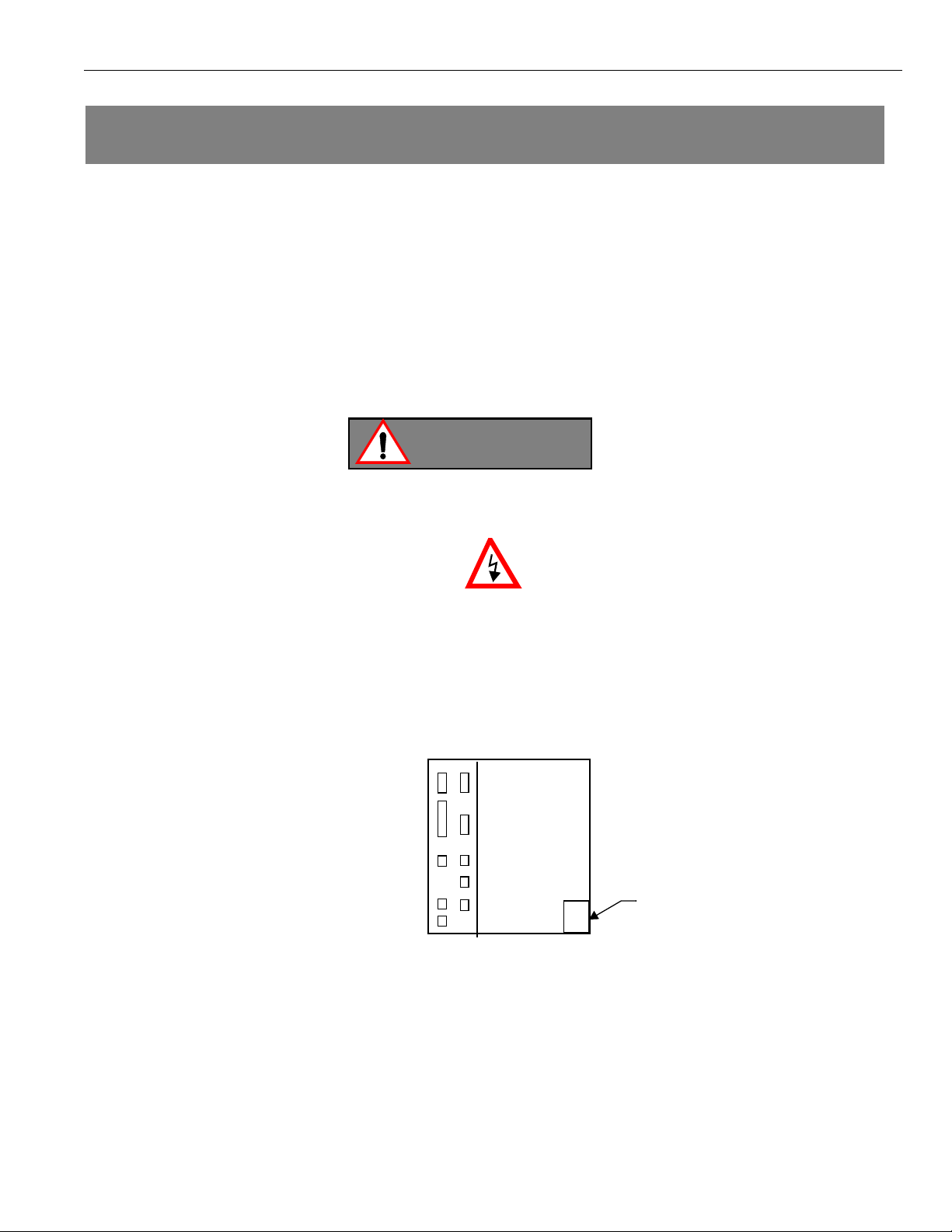
SPECIAL SAFETY NOTE: This symbol indicates that ELECTRICAL SHOCK HAZARD
condition exists. DO NOT TOUCH any electrical connection terminals when the power is on, and
for at least 5 minutes after switching off the power supply. Warning label is located on the PCNC
PCNC Unit
xxxxxxxxx
xxxxxxxxx
xxxxxxxxx
xxxxxxxxx
xxxxxxxxx
WARNING LABEL
NOTICE
Printed _______. 1999. The informatio n contained within thi s document is the propri etary property of
Yasakawa Electric America , Inc. , and ma y not be copied, reproduc ed or transmitted to oth er parties without
the expressed wr itte n authorization of Yasakawa Electric America, Inc .
No pattent liability is assumed with respect to the uses of the information contained herein. Moreover,
becaus e Yas kawa is constantly improving its hig h qu ality product, the information cont ained in this manua l
is subject to chan ge without notice. Every precaution has been taken in th e pre p a ration of this docu m ent .
i
Page 3

YASNAC PCNC Prog ramming Manual Introductio n
INFORMATION INDICATORS
The following symbols are used in this opera t ing manual to emphasi ze particular informa tion to the user:
Indicates important information to be remembered, i.e., precautionary alarm
POINT
displays to prevent damaging devices.
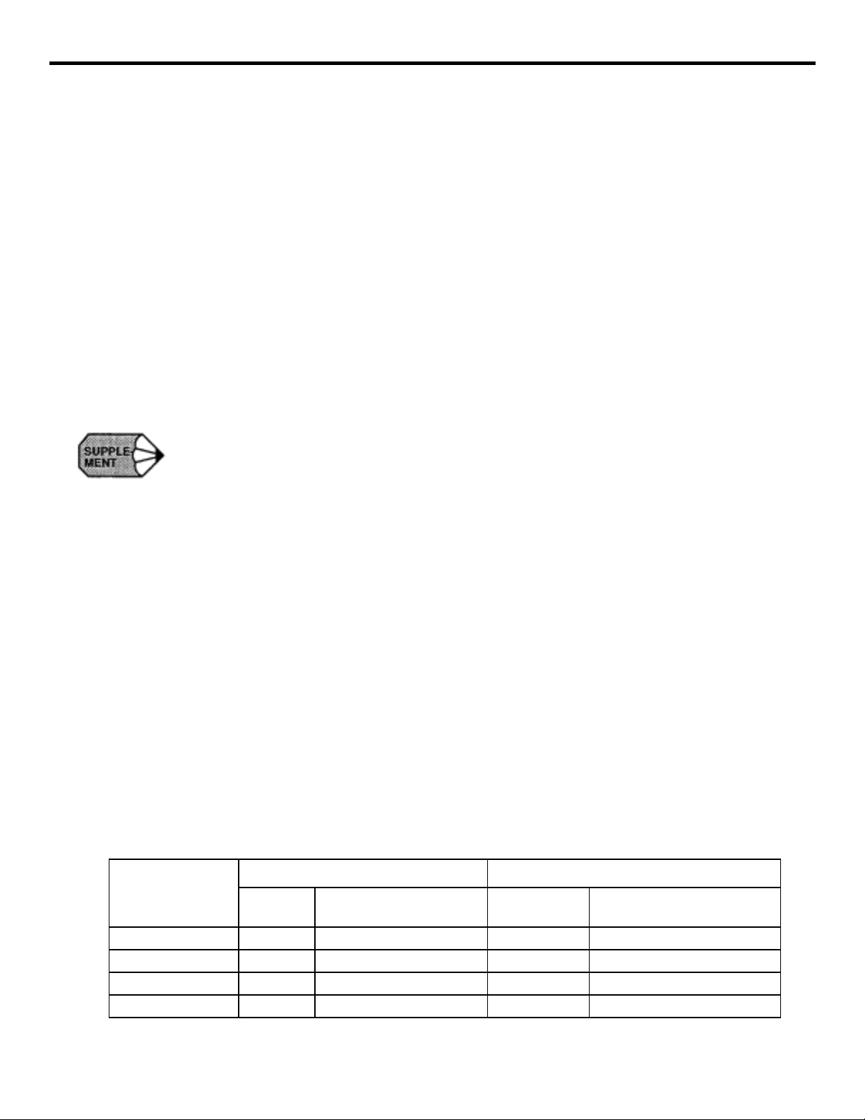
SUPPLEMENT
TERMS
Indicates supplementary material.
Indicates definitions of terminology that has not been explained before.
NOTES REGARDING SAFE OPERATION
It is important that the user should read this manual before installing, operating, performing any
maintenance or inspecting the
<$61$&3&1&
Also, the functions and performance of a NC machine tool
are not determined by the CNC unit it sel f, t he r efore thoroughly rea d and familiarize yourself with the
machine builder’s documentation concerning the safe and most efficient ways to use the machine tool.
Nevertheless, Yasakawa assumes no responsibility for damages resulting from the use of the information
contained wit hi n thi s publication.
ii
Page 4

YASNAC PCNC Prog ramming Manual Introductio n
Table of Contents
1. PROGRAMMING BASICS
1.1 FUNDAMENTALS OF PROGRAMMING TERMINOLOGY . . . . . . . . . . . . . . . .1-2
1.1.1 Numerically Controlled Axes and the Number of Sim ult a neously Controllable
Axes . . . . . . . . . . . . . . . . . . . . . . . . . . . . . . . . . . . . . . . . . . . . . . . . . . . . . . . .1-2
1.1.2 Least Input Increment and Least Output Increment . . . . . . . . . . . . . . . . . . .1-6
1.1.3 Maximu m Programmable Values for Axis Movement . . . . . . . . . . . . . . . . .1-8
1.1.4 Optio nal Block Skip (/1), (/2 to /9) * . . . . . . . . . . . . . . . . . . . . . . . . . . . . . .1-11
1.1.5 Buffer Register and Multi-active R egister . . . . . . . . . . . . . . . . . . . . . . . . . .1-12
1.2 BASICS OF FEED FUNCTION . . . . . . . . . . . . . . . . . . . . . . . . . . . . . . . . . . . . . . .1-13
1.2.1 Rapid Traverse . . . . . . . . . . . . . . . . . . . . . . . . . . . . . . . . . . . . . . . . . . . . . . .1-13
1.2.2 Cutting Feed (F Command) . . . . . . . . . . . . . . . . . . . . . . . . . . . . . . . . . . . . .1-13
1.2.3 F1-Digit Feed* . . . . . . . . . . . . . . . . . . . . . . . . . . . . . . . . . . . . . . . . . . . . . . .1-16
1.2.4 Feed per Minute Function (G94) . . . . . . . . . . . . . . . . . . . . . . . . . . . . . . . . .1-18
1.2.5 Solid Tap Mode (G93, G94) * . . . . . . . . . . . . . . . . . . . . . . . . . . . . . . . . . . .1-18
1.2.6 Automatic Accelerati on and Deceleration . . . . . . . . . . . . . . . . . . . . . . . . . .1-19
2. COMMAND CALLING AXIS MOVEMENTS
2.1 INTERPOLATION COMMANDS . . . . . . . . . . . . . . . . . . . . . . . . . . . . . . . . . . . . . .2-2
2.1.1 Positioning (G00, G06, G60) . . . . . . . . . . . . . . . . . . . . . . . . . . . . . . . . . . . . .2 -2
2.1.2 Linear Interpolation (G01) . . . . . . . . . . . . . . . . . . . . . . . . . . . . . . . . . . . . . . .2-4
2.1.3 Circular Interpolation (G02, G0 3) . . . . . . . . . . . . . . . . . . . . . . . . . . . . . . . . .2-5
2.1.4 Helical Interpolation (G02, G03)* . . . . . . . . . . . . . . . . . . . . . . . . . . . . . . . .2-11
2.2 REFERENCE POINT RETURN . . . . . . . . . . . . . . . . . . . . . . . . . . . . . . . . . . . . . . .2-13
2.2.1 Automatic Return to Reference Point (G28) . . . . . . . . . . . . . . . . . . . . . . . .2-13
2.2.2 Reference Point Return Check (G27) . . . . . . . . . . . . . . . . . . . . . . . . . . . . .2-1 7
2.2.3 Return from Reference Point Return (G29) . . . . . . . . . . . . . . . . . . . . . . . .2-18
2.2.4 Second to Fourth Refer ence Point Return (G30) . . . . . . . . . . . . . . . . . . . . .2-22
iii
Page 5

YASNAC PCNC Prog ramming Manual Introductio n
3. MOVEMENT CONTROL COMMANDS
3.1 SETTING THE COORDINATE SYSTEM . . . . . . . . . . . . . . . . . . . . . . . . . . . . . . .3-3
3.1.1 Selecting the Coo rdinate System . . . . . . . . . . . . . . . . . . . . . . . . . . . . . . . . . .3-3
3.1.2 Base C oordinate System (G92) . . . . . . . . . . . . . . . . . . . . . . . . . . . . . . . . . . .3-3
3.1.3 Workpiece Coordinate System (G54 to G59)* . . . . . . . . . . . . . . . . . . . . . . .3-5
3.1.4 Local Coordinate System (G52 Q2)* . . . . . . . . . . . . . . . . . . . . . . . . . . . . .3-12
3.1.5 Machin e Coordinate System (G53) . . . . . . . . . . . . . . . . . . . . . . . . . . . . . . .3-13
3.1.6 Rotation of Coordinate System (G68, G6 9)* . . . . . . . . . . . . . . . . . . . . . . .3-16
3.1.7 Plane Selection (G17, G18, G19) . . . . . . . . . . . . . . . . . . . . . . . . . . . . . . . .3-18
3.2 DETERMINING THE COORDINATE VALUE INPUT MODES . . . . . . . . . . . .3-19
3.2.1 Absolute/Incremental Designation (G90, G91) . . . . . . . . . . . . . . . . . . . . . .3-19
3.2.2 Inch/ Metric Input Designation (G20, G21) . . . . . . . . . . . . . . . . . . . . . . . . .3-21
3.2.3 Scaling (G50, G51) * . . . . . . . . . . . . . . . . . . . . . . . . . . . . . . . . . . . . . . . . . .3-22
3.3 TIME-CONTROLLING COMMANDS . . . . . . . . . . . . . . . . . . . . . . . . . . . . . . . . .3-26
3.3.1 Dwell ( G04) . . . . . . . . . . . . . . . . . . . . . . . . . . . . . . . . . . . . . . . . . . . . . . . . .3-26
3.3.2 Exact Stop (G09) . . . . . . . . . . . . . . . . . . . . . . . . . . . . . . . . . . . . . . . . . . . . .3-26
3.3.3 Exact Stop Mode (G61, G64) . . . . . . . . . . . . . . . . . . . . . . . . . . . . . . . . . . .3-26
3.4 TOOL OFFSET FUNCTIONS . . . . . . . . . . . . . . . . . . . . . . . . . . . . . . . . . . . . . . . .3-28
3.4.1 Tool O ffset Data Memory . . . . . . . . . . . . . . . . . . . . . . . . . . . . . . . . . . . . . .3-28
3.4.2 Tool Length Offset (G43, G44, G49) . . . . . . . . . . . . . . . . . . . . . . . . . . . . .3-29
3.4.3 Tool P osition Offset (G45 to G48) . . . . . . . . . . . . . . . . . . . . . . . . . . . . . . .3-32
3.4.4 Radius Offset C Functio n (G40, G41, G42) * . . . . . . . . . . . . . . . . . . . . . . .3-40
3.4.5 3-Dimensio nal Tool Offset Function (G40, G41, G4 2)* . . . . . . . . . . . . . .3-78
3.5 S, T, M, AND B Functio ns . . . . . . . . . . . . . . . . . . . . . . . . . . . . . . . . . . . . . . . . . . .3-85
3.5.1 Spindle Function (S Function) . . . . . . . . . . . . . . . . . . . . . . . . . . . . . . . . . . .3-8 5
3.5.2 Tool F unction (T Function) . . . . . . . . . . . . . . . . . . . . . . . . . . . . . . . . . . . . .3-86
3.5.3 Miscellaneous Function (M Function) . . . . . . . . . . . . . . . . . . . . . . . . . . . .3-87
3.5.4 Second Miscellaneous Function (B Function) * . . . . . . . . . . . . . . . . . . . . .3-89
iv
Page 6

YASNAC PCNC Prog ramming Manual Introductio n
4.1 PROGRAM SUPPORT FUNCTIONS (1) . . . . . . . . . . . . . . . . . . . . . . . . . . . . . . . .4-3
4.1.1 Canned Cycles (G73 to G89, G181 to G189) * . . . . . . . . . . . . . . . . . . . . . . .4-3
4.1.2 Hole Machining Pattern Cycles (G70, G7 1, G72) * . . . . . . . . . . . . . . . . . .4-32
4.1.3 Solid Tap Function (G84, G74) * . . . . . . . . . . . . . . . . . . . . . . . . . . . . . . . .4-36
4.1.4 Deep-hole Solid Tap Function (G184, G174)* . . . . . . . . . . . . . . . . . . . . . .4-46
4.1.5 Circle Cutting Function (GI2, G13) . . . . . . . . . . . . . . . . . . . . . . . . . . . . . .4-57
4.1.6 Mirror Image ON/OFF (M94, M95) * . . . . . . . . . . . . . . . . . . . . . . . . . . . . .4-61
4.1.7 Programmable Data Input (G10) * . . . . . . . . . . . . . . . . . . . . . . . . . . . . . . .4-64
4.1.8 Subprogram Call Up Function (M98, M99) . . . . . . . . . . . . . . . . . . . . . . . .4-67
4.2 PROGRAM SUPPORT FUNCTIONS (2) . . . . . . . . . . . . . . . . . . . . . . . . . . . . . . .4-69
4.2.1 Program Copy (G25)* . . . . . . . . . . . . . . . . . . . . . . . . . . . . . . . . . . . . . . . . .4-69
4.2.2 Automatic Corner Override (G106) * . . . . . . . . . . . . . . . . . . . . . . . . . . . . .4-72
4.2.3 Store d Stroke Limit B and C (G22, G23) * . . . . . . . . . . . . . . . . . . . . . . . . .4-77
4.2.4 Break Point Function . . . . . . . . . . . . . . . . . . . . . . . . . . . . . . . . . . . . . . . . . .4-82
4.2.5 High-speed Cutting * . . . . . . . . . . . . . . . . . . . . . . . . . . . . . . . . . . . . . . . . . .4-82
4.2.6 Chamfering and Corner Rounding Commands * . . . . . . . . . . . . . . . . . . . .4-85
4.2.7 Corner Feedrate Designa tion (G107, G108)’ . . . . . . . . . . . . . . . . . . . . . . .4-89
4.3 AUTOMATING SUPPORT FUNCTIONS . . . . . . . . . . . . . . . . . . . . . . . . . . . . .4-102
4.3.1 Skip Function (G31) * . . . . . . . . . . . . . . . . . . . . . . . . . . . . . . . . . . . . . . . .4-102
4.3.2 Program interrupt Function (M90, M91)* . . . . . . . . . . . . . . . . . . . . . . . . .4-105
4.3.3 Tool Life Control Function * . . . . . . . . . . . . . . . . . . . . . . . . . . . . . . . . . . .4-107
4.4 MACROPROGRAMS . . . . . . . . . . . . . . . . . . . . . . . . . . . . . . . . . . . . . . . . . . . . . .4-114
4.4.1 Differences from Subprograms . . . . . . . . . . . . . . . . . . . . . . . . . . . . . . . . .4-114
4.4.2 Microprogram Call (G65, G66, G67) . . . . . . . . . . . . . . . . . . . . . . . . . . . .4-115
4.4.3 Variables . . . . . . . . . . . . . . . . . . . . . . . . . . . . . . . . . . . . . . . . . . . . . . . . . .4-126
4.4.4 Operation Instructions . . . . . . . . . . . . . . . . . . . . . . . . . . . . . . . . . . . . . . . .4-155
4.4.5 Control Instructions . . . . . . . . . . . . . . . . . . . . . . . . . . . . . . . . . . . . . . . . . .4-15 7
4.4.6 Registering the Microprogram . . . . . . . . . . . . . . . . . . . . . . . . . . . . . . . . . .4-163
4.4.7 Micro program Alarm Numbers . . . . . . . . . . . . . . . . . . . . . . . . . . . . . . . . .4-164
4.4.8 Examples of Microprograms . . . . . . . . . . . . . . . . . . . . . . . . . . . . . . . . . . .4-165
v
Page 7

YASNAC PCNC Prog ramming Manual Introductio n
USING THIS MANUAL
This manual decribes the procedures for operating the
<$61$&3&1&
RELATED INFORMATION SOURCES
For additonal information, refer to the follow in g ma nuals:
TITLE OF DOCUMENT CONTENTS
YASNAC PCNC Programming Manual
(YEA-SIA-C844-2.2)
YASNAC PCNC/PLC Programming Manual
(YEA-SIA-C844-0.1)
YASNAC PCNC I/O Signal Manual
(YEA-SIA-C844-2.3)
YASNAC PCNC Connection Manual
(YEA-SIA-C844-0.2)
YASNAC PCNC Maintenance Manual
(YEA-SIA-C844-2.9)
.
PCNC Program creation instructions
PLC Program crea tion instructions
Describes functions between PCNC and PLC
Instructions for connecting PCNC with machines,
machine interface and peripheral equipment
Describes service and maintenance procedures.
CAUTIONS
This manual descri be s all the opt ion functions (identifie d by th e “*” symbol) but some of these may not
be available with your YA SN AC PCNC. To determine the option functions installed in your PCNC,
refer to the specific ation document or ma nuals published by the ma chine tool builder.
Unless otherwise specified, the following conditions apply in programming explanations and
programming examples.
l
Metric system for input and metric system for out put / movement
l
Zero point in the base coordinate system
l
Reference point
Yaskawa has made every effort to describe individ ual functions and their relationships to other functions
as accurately as possible . Howe ve r, there are m any thi ngs th at cannot or must not be perform e d and it is
not possible to describe all of these. Accordingly, readers are requested to understand that unless it is
specifically stated th at some t hin g can be performed, it should be assumed that it cannot be pe rformed.
Also, bear in mind that the performance and functions of an PCNC machine tool are not determined
solely by th e PCNC unit. The entire control system consists of the mechanical system, then machine
operation panel a nd ot her machine related equipment in addit ion to the PCNC. Theref ore, read the
manuals published by the machine tool builder for detailed information relating to the machine.
vi
Page 8

YASNAC PCNC Programming Manual Chapter 1: Programmi ng Basics
1
Programming Basics
Chapter 1 describes the basic terms used in programming and the feed
functions.
1.1 FUNDAMENTALS OF PROGRAMMING TERMINOLOGY . . . . . . . . . . . . . . . 1-2
1.1.1 Numerically Controlled Axes an d the Number of Simu ltaneously Controlla ble
Axes . . . . . . . . . . . . . . . . . . . . . . . . . . . . . . . . . . . . . . . . . . . . . . . . . . . . . . . 1-2
1.1.2 Least Input Increment and Least Output Increment . . . . . . . . . . . . . . . . . . 1-6
1.1.3 Maximu m Programmable Values for Axis Movement . . . . . . . . . . . . . . . . 1-8
1.1.4 Optio nal Block Skip (/1), (/2 to /9) * . . . . . . . . . . . . . . . . . . . . . . . . . . . . . 1-11
1.1.5 Buffer Register and Multi-active R egister . . . . . . . . . . . . . . . . . . . . . . . . . 1-12
1.2 BASICS OF FEED FUNCTION . . . . . . . . . . . . . . . . . . . . . . . . . . . . . . . . . . . . . . 1-13
1.2.1 Rapid Traverse . . . . . . . . . . . . . . . . . . . . . . . . . . . . . . . . . . . . . . . . . . . . . . 1-13
1.2.2 Cutting Feed (F Command) . . . . . . . . . . . . . . . . . . . . . . . . . . . . . . . . . . . . 1-13
1.2.3 F1-Digit Feed* . . . . . . . . . . . . . . . . . . . . . . . . . . . . . . . . . . . . . . . . . . . . . . 1-16
1.2.4 Feed per Minute Functio n (G94) . . . . . . . . . . . . . . . . . . . . . . . . . . . . . . . . 1-18
1.2.5 Solid Tap Mode (G93, G94) * . . . . . . . . . . . . . . . . . . . . . . . . . . . . . . . . . . 1-18
1.2.6 Automatic Acceleration and Deceleration . . . . . . . . . . . . . . . . . . . . . . . . . 1-19
1 - 1
Page 9
YASNAC PCNC Programming Manual Chapter 1: Programmi ng Basics
1.1 FUNDAMENTALS OF PROGRAMMING TERMINOLOGY
This section describes the “basic terms used in programmin g.
1.1.1 Numerically Controlled Axes and the Number of Simultaneously Controllable
(1) Numerically Controlled Axes and Axes Names
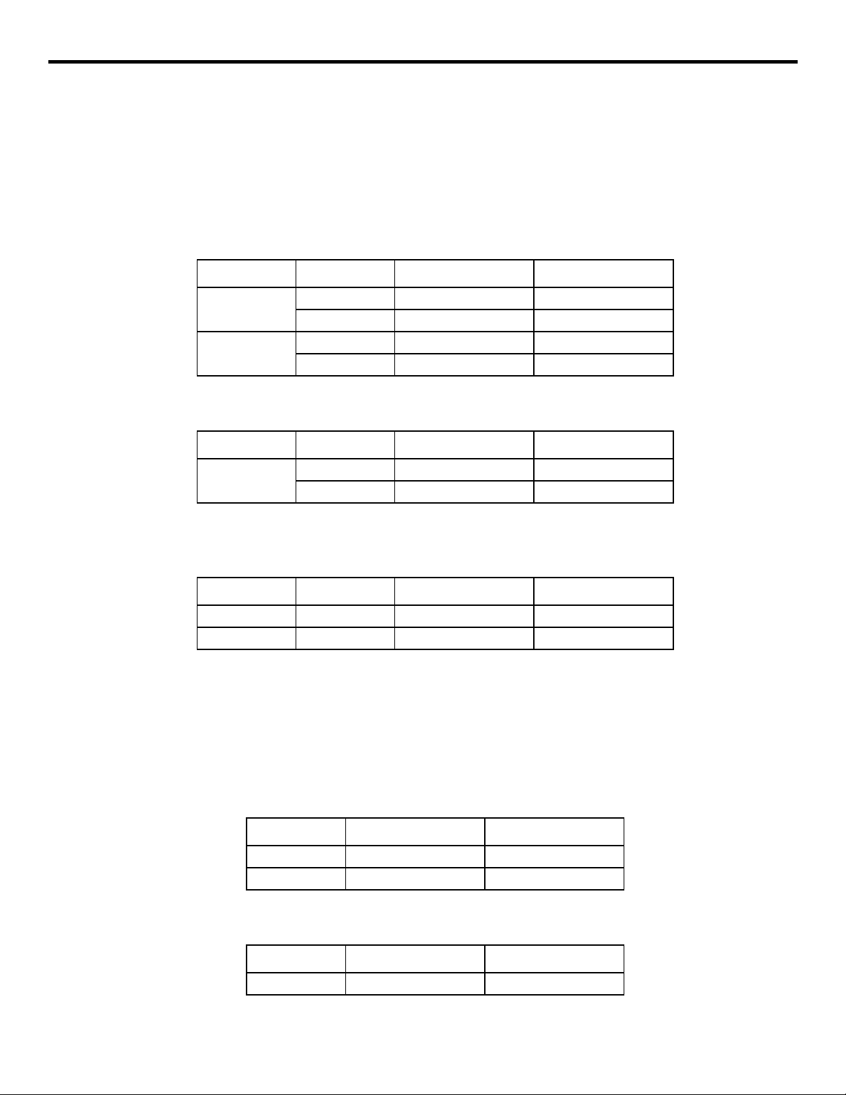
The numerically controlled axes and the axis na m es are indicated in Table 1.1.1.1.
Table 1.1.1.1: Numerically Controlled Axes
Controlled Axis Axis Name Model Name Descr ipt i o n
Basic axes X, Y, Z
*
4th and 5th axes
U, V, W
A, B, C
or
Represents the coordinate position or distance in or along an axis
indicated by X, Y, and Z.
Represents the commands of the fourth and fifth axes. For rotary
motion, address characters A, B, and C are used and for parallel (linear) motion, address characters U, V, and W are used.
(2) Number of Simultaneously Controlla bl e Axes
With the standar d specificat ion, up to thre e axes can be controlled simultane ous ly. This number can be increased optionally to fou r and five axes.
(a) Number of simultaneously controlla ble axes with the 3-ax is control function
The number of simulta.neously controllable axes is indi cated in Table 1.2.
Axes
Table 1.1.1.2: The Number of Simultaneously Controlla b le Axes w i th 3-ax is
Control Function
Number of Simultaneously Controllable Axes
Positioning (G00) 3 axes (X-, Y-, and Z-axis)
Linear interpolation (G01) 3 axes (X-, Y-, and Z-axis)
Circular interpolation (G02, G03) 2 axes (X- and Y-axis, Y- and Z-axis, or Z- and X-axis)
*Circle cutting (G12, G13) 2 axes (X- and Y-axis)
*Helical interpolation (G02, G03)
Manual operation 3 axes (X-, Y-, and Z-axis)
Note 1: The plane in which circular interpolation is executed is determined by the plane selection G
code (G 17 to G19) which is presently valid. For details, see 2.1.3, “Circular Interpolation
(G02, G03)”.
2: With a manual pulse generator, simultaneous control is possible in either one or three axes.
2 axes (circular interpolation in XY plane)
1 axis (linear interpolation, Z-axis)
See 2.1.4, “Helical Interpolation (G02, G03)”.
Simultaneous
3-axis control
1 - 2
Page 10
YASNAC PCNC Programming Manual Chapter 1: Programmi ng Basics
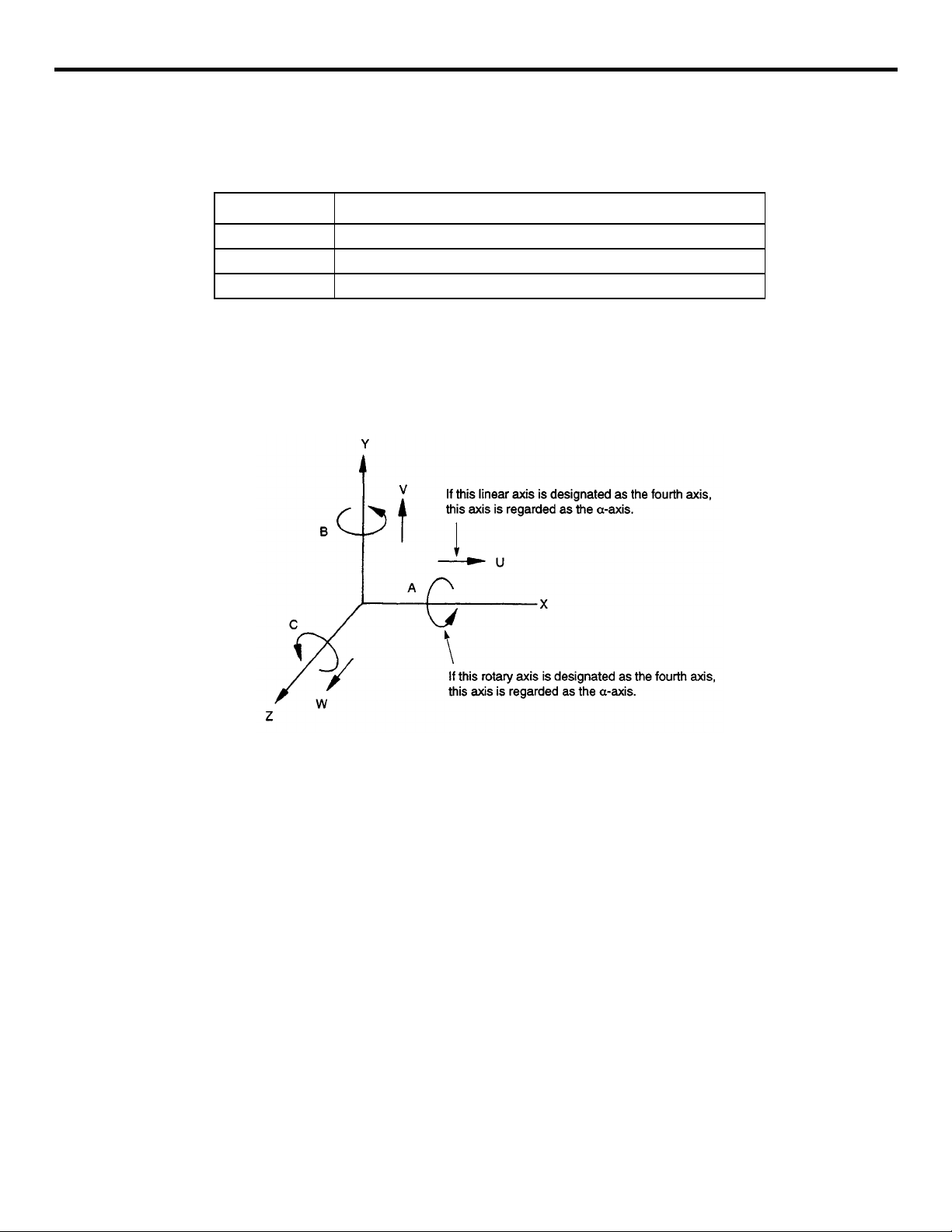
(b) Number of simultaneously controlla ble axes with the 4-ax is control function*
The four th axis can be s elected op tionally. In this manu al, the four th axis is ref er r ed to as
“a-axis” and represents any of six axes – A, B, C, U, V, and W. Which ad dress characters
should be used for the fou rth axi s is set for parameters pm1109, pm1110, and pm1111,
and pm1151, pm1152, and pm1153. The number of simulta neously controllable axes is
indicated in Table 1.3.
Table 1.1.1.3: The Number of Simultaneously Controlla b le Axes w i th 4-ax is
Control Function
Number of Simultaneously Controllable Axes
Positioning (G00) 4 axes (X-. Y-, Z-, and a-axis)
Linear interpolation (G01) 4 axes (X-. Y-, Z-, and a-axis)
Circular interpolation (G02, G03)
*Circle cutting (G12, G13) 2 axes (X- and Y-axis)
*Helical interpolation (G02, G03)
2 axes (X- and Y-axis, Y- and Z-axis, or Z- and X-axis)
2 axes (X- and
2 axes (circular interpolation in XY plane)
1 axis (linear interpolation, Z-axis)
See 2.1.4, “Helical Interpolation (G02, G03)”.
a-axis, Y- and a-axis, or Z- and α-axis)
Simultaneous
3-axis control
Manual operation 4 axes (X-, Y-, and
Note 1: If “a” is included in circular interpolation, it must be a linear axis (U, V, or W). The plane in
which circular interpolation is executed is determined by the plane selection G code (G17 to
G19) which is presently valid. For details, see 2.1.3, “Circular Interpolation (G02, G03)”.
2: With a manual pulse generator, simultaneous control is possible in either one or three axes.
For the a-ax is , either a rotary axis or a linear axis can be se le cted.
• A rotary axis (A-, B-, or C-axi s ) is de fin ed as indicated in Table 1.4.
Table 1.1. 1 . 4: Rotary A xes
Rotary Axis Definition
A-axis Rotary axis around an axis which is parallel to X-axis
B-axis Rotary axis around an axis which is parallel to Y-axis
C-axis Rotary axis around an axis which is parallel to Z axis
Note 1: The unit of output increment (motion increment) and input increment for a rotary axis is
“degrees” inste ad of ‘“mm” which i s u sed for a linear axis (X- , Y-,Z-axis). With the exception
of the unit, a rotary axis can be treated in the same manner as a l i near axis . (Metric system)
(The NC circulates feedrate assuming 0.001 deg. as 0.001 mm.)
a-axis)
2: Even if the dimensions are changed to i n ch es by using the inch/mm sele ct ion function, the unit
system for a rotary axis remains unchanged (degrees).
1 - 3
Page 11
YASNAC PCNC Programming Manual Chapter 1: Programmi ng Basics
• A linear axis (U-, V-, or W-ax is) i s defined as indicated in Table 1.5.
Table 1.1.1.5: Linear Axes
Linear Axis Definition
U-axis A linear axis parallel to X-axis.
V-axis A linear axis parallel to Y-axis.
W-axis A linear axis parallel to Z-axis.
Note 1: The unit of ou tput increment (motion i ncr em en t) and input increment o f l i nea r axis is the same
as other linear axes (X-, Y-, and Z-axis). The linear axes indicated above can be treated in
exactly the same manner as other linear axes.
2: When the inch system is selected by using inch/mm selection function, dimensions must be
input in units of inches as with other axes (X-, Y-, and Z-axis)
Fig. 1.1.1.1 Fourth Axis (a-axis) in the R ight-hand Coo rdinate Syste m
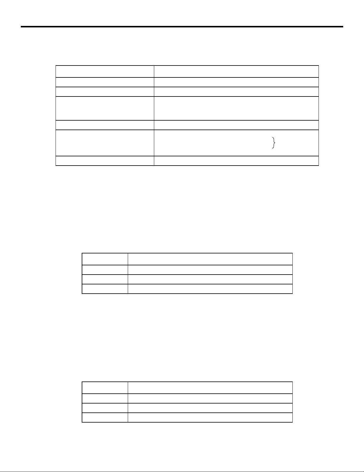
(c) Number of simultaneously controlla ble axes with the 5-ax is control function*
The fifth axis ca n be selected option al ly. In this manual, the fifth axis is referred to as “b-
axis” and repr ese nts a ny of si x axe s – A, B, C, U, V, and W. Which address characters
should be used for the fifth axi s is set fo r par am e terspm1112, pm 1113, and pm1114, and
pm1154, pm1155, and pm1156. The number of simultaneously cont rollable axes is indicated in Table 1.6.
1 - 4
Page 12
YASNAC PCNC Programming Manual Chapter 1: Programmi ng Basics
Table 1.1.1.6: The Number of Simultaneously Control la ble Axes with 5-axis Control
Function
Number of Simultaneously Controllable Axes
Positioning (G00) 5 axes (X-. Y-, Z-, α-, and β-axis)
Linear interpolation (G01) 5 axes (X-. Y-, Z-, α-, and β-axis)
2 axes (X- and Y-axis, Y- and Z-axis, or Z- and X-axis)
Circular interpolation (G02, G03)
*Circle cutting (G12, G13) 2 axes (X- and Y-axis)
*Helical interpolation (G02, G03)
Manual operation 5 axes (X-, Y-, Z-,and α-axis)
Note 1: Circular interpolation is possible only when a- and b-axis are linear axes. The plane in which
circular interpolation is executed is determined by the plane selection G code (G17 to G19)
which is presently valid. For details, see 2.1.3, “Circular interpolation (G02, G03)”.
2: With a manual pulse ge nerator, simultaneous control is possible in either one or three axes.
2 axes (X- and a-axis, Y- and α-axis, or Z- and α-axis)
2 axes (X- and b-axis, Y- and β-axis, or Z- and β-axis)
2 axes (circular interpolation in XY plane))
1 axis (linear interpolation, Z-axis)
See 2.1.4, “Helical Interpolation (G02, G03)”.
Simultaneous
3-axis control
For the b-axis, eith er a rotary axis or a linear axis can be selected.
• A rotary axis (A-, B- , or C-axis) is defined as indi ca te d in Tabl e 1. 1. 1. 7.
Table 1.1.1.7: Rotary Axes
Rotary Axis Definition
A-axis Rotary axis around an axis which is parallel to X-axis
B-axis Rotary axis around an axis which is parallel to Y-axis
C-axis Rotary axis around an axis which is parallel to Z axis
Note 1: The unit of output increment (motion increment) and input increment for a rotary axis is
“degrees” instea d of “mm” which is used for a linear axis (X-, Y -, Z-axis). With the exception
of the unit, a rotary axis can be treated in the same manner as a l i near axis . (Metric system)
(The NC calculates feedrate assuming 0.001 deg. as 0.001mm.)
2: Even if the dimensions are changed to i n ch es by using the inch/mm sele ct ion function, the unit
system for a rotary axis remains unchanged (degrees).
• A linear axis (U-, V-, or W-ax is) i s defined as indicated in Table 1.1.1.8.
Table 1.1.1.8: Linear Axes
Linear Axis Definition
U-axis A linear axis parallel to X-axis.
V-axis A linear axis parallel to Y-axis.
W-axis A linear axis parallel to Z-axis.
1 - 5
Page 13
YASNAC PCNC Programming Manual Chapter 1: Programmi ng Basics
Note 1: The unit of output increment (motion increment) and input increment of a linear axis is the
same as other linear axes (X-, Y-, and Z-axis). The linear axes indicated above can be treated
in exactly the same manner as other linear axes,
2: When the inch system is selected by using inch/nm selection function, dimensions must be
input in units of inches as with other axes (X-, Y-, and Z-axis).
Fig. 1.1.1.2 Fifth Axis (b-axis) in the Right-hand Coordinate System
1.1.2 Least Input Increment and Least Output Increment
The least input and output increments vary depending on the type of controlled axis whether it is a
rotary axis or a linear axis.
(1) Least Input Increment
The least input inc re ment to express axis mo vement distance tha t is input by using punched
tape or manual dat a i nput switches is indica te d in Tables 1.9, 1.10, and 1.11.
Table 1.1.2.1: Least Increment (Standard)
Linear Axis *Rotary Axes
Metric Input 0.001 mm 0.001 deg.
Inch Input 0.0001 inch 0.001 deg.
Table 1.1.2.2: Least Increment (Sub Microns)
Linear Axis *Rotary Axes
Metric Input 0.0001 mm 0.001 deg.
Inch Input 0.00001 inch 0.001 deg.
1 - 6
Page 14
YASNAC PCNC Programming Manual Chapter 1: Programmi ng Basics
Table 1.1.2.3: Least Increment (Sub Sub-microns)
Linear Axis *Rotary Axes
Metric Input 0.00001 mm 0.001 deg.
Inch Input 0.000001 inch 0.001 deg.
Note: Selection o f “mm-input” and “inch-input” is made by the setting parameter pm0007 D0.
(2) Least Output Increment
The least output increment indicates the “minimum unit” of axis moveme nt t hat i s d eter mined
by the mechanical system. By selecting the option, it is possible to select the output unit system between “mm” and “inches”.
Table 1.1.2.4: Least Output Unit (Standard)
Linear Axis *Rotary Axes
Metric Output 0.001 mm 0.001 deg.
Inch Output 0.0001 inch 0.001 deg.
Table 1.1.2.5: Least Increment (Sub Microns)
Linear Axis *Rotary Axes
Metric Output 0.0001 mm 0.001 deg.
Inch Output 0.00001 inch 0.001 deg.
Table 1.1.2.6: Least Increment (Sub Sub-microns)
Linear Axis *Rotary Axes
Metric Output 0.00001 mm 0.001 deg.
Inch Output 0.000001 inch 0.001 deg.
1 - 7
Page 15
YASNAC PCNC Programming Manual Chapter 1: Programmi ng Basics
1.1.3 Maximum Program mable Values for Axis Movement
The maximum programmable values that can be designated for a move command are indicated in
Tables 1.15, 1.16, and 1. 17. The maximum programmable val ues i ndicated in these t ab le s are
applicable to ad dresses I, J, K, R, and Q which ar e use d for designating “distance” in addition to
the move comma nd a ddresses X, Y, Z, a, and b.
Table 1.1.3.1: Maximum Programmable Value s for Axis Movement (Standard)
Linear Axis *Rotary Axes
Metric Output
Inch Output
Metric Input ±999999.999 mm ±999999.999 deg.
Inch Input ±39370.0787 mm ±999999.999 deg.
Metric Input ±999999.999 mm ±999999.999 deg.
Inch Input ±999999.999 mm ±999999.999 deg.
Table 1.1.3.2: Maximum Programmable Values for Axis Movement (Sub-microns)
Linear Axis *Rotary Axes
Metric Output
Metric Input ±999999.999 mm ±999999.999 deg.
Inch Input ±39370.0787 mm ±999999.999 deg.
Table 1.1.3.3: Maximum Programmable Values for Axis Movement
(Sub Sub-microns)
Linear Axis *Rotary Axes
Metric Output Metric Input ±999999.999 mm ±999999.999 deg.
Inch Output Inch Input ±39370.0787 mm ±999999.999 deg.
In incremental programming, the values to be d esignated must not exceed the maximum programmable values indicated above. In absolute programming, the move distance of each axis
must not exce ed t he max imum prog ramma ble v alu es in dica ted a bove. I n addi tio n to the note s
indicated above , it m ust a lso be ta ke n in to c onsideration that the cum ul ative values of move
command must not exceed the val ues indicted in Tables 1.18, 1.19, and 1.20.
Table 1.1.3.4: Maximum Cumulative Values (Standard)
Linear Axis *Rotary Axes
Metric Input ±999999.999 mm ±999999.999 deg.
Inch Input ±999999.999 inch ±999999.999 deg.
Table 1.1.3.5: Maximum Programmable Values for Axis Movement (Sub-microns)
Linear Axis *Rotary Axes
Metric Input ±999999.999 mm ±999999.999 deg.
1 - 8
Page 16
YASNAC PCNC Programming Manual Chapter 1: Programmi ng Basics
Table 1.1.3.6: Maximum Programmable Va lues for Axis Move me nt (Sub Sub-
microns)
Linear Axis *Rotary Axes
Metric Input ±999999.999 mm ±999999.999 deg.
Note: The values indicated above do not depend on the “least output increment”.
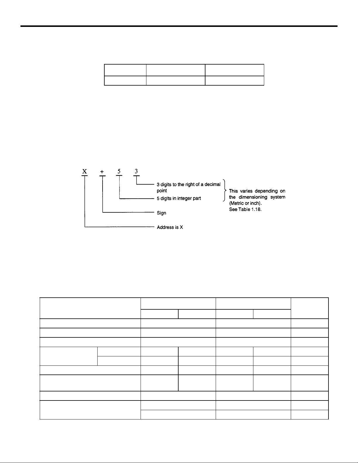
(1) Programmable Range (Input Form at )
This model of NC adopts the variable block format which complies with JIS B6313.
Programmable range of individual addresses is indicated in Table 1.1.3.7. The numbers given
in this tab le indicate the allowable maximum number of digits.
An example of input forma t is given below.
Input data should be entered without a de cimal point. If a deci m al p oi nt i s use d, th e entered
values is tr eated in a different ma nn er. Leading zeros and the “+” (plus) sign can be omitted
for all kinds of addre ss data including sequenc e number. Note that, however, the “-” (minus)
sign cannot be omitte d.
Table 1.1.3.7: Input Format (Standard)
Address
Program number O5 O5 B
Sequence number N5 N5 B
G function G3 G3 B
Coordinate words
Feed per minute (mm/min) F60 F41 F60 F51 B
Feed per minute (mm/min)
1/10 function
S function S 5 S5 B
T function
Linear axis a+63 a+54 a+63 a+54 B
Rotary axis b+63 b+63 b+63 b+6 3 O
Metric Output Inch Output
Metric Input Metric I nput Metric Input Metri c Input
F61F42F61F52 B
T 2 T2 B
T 4 T4 O
B: Basic
O: Option
1 - 9
Page 17
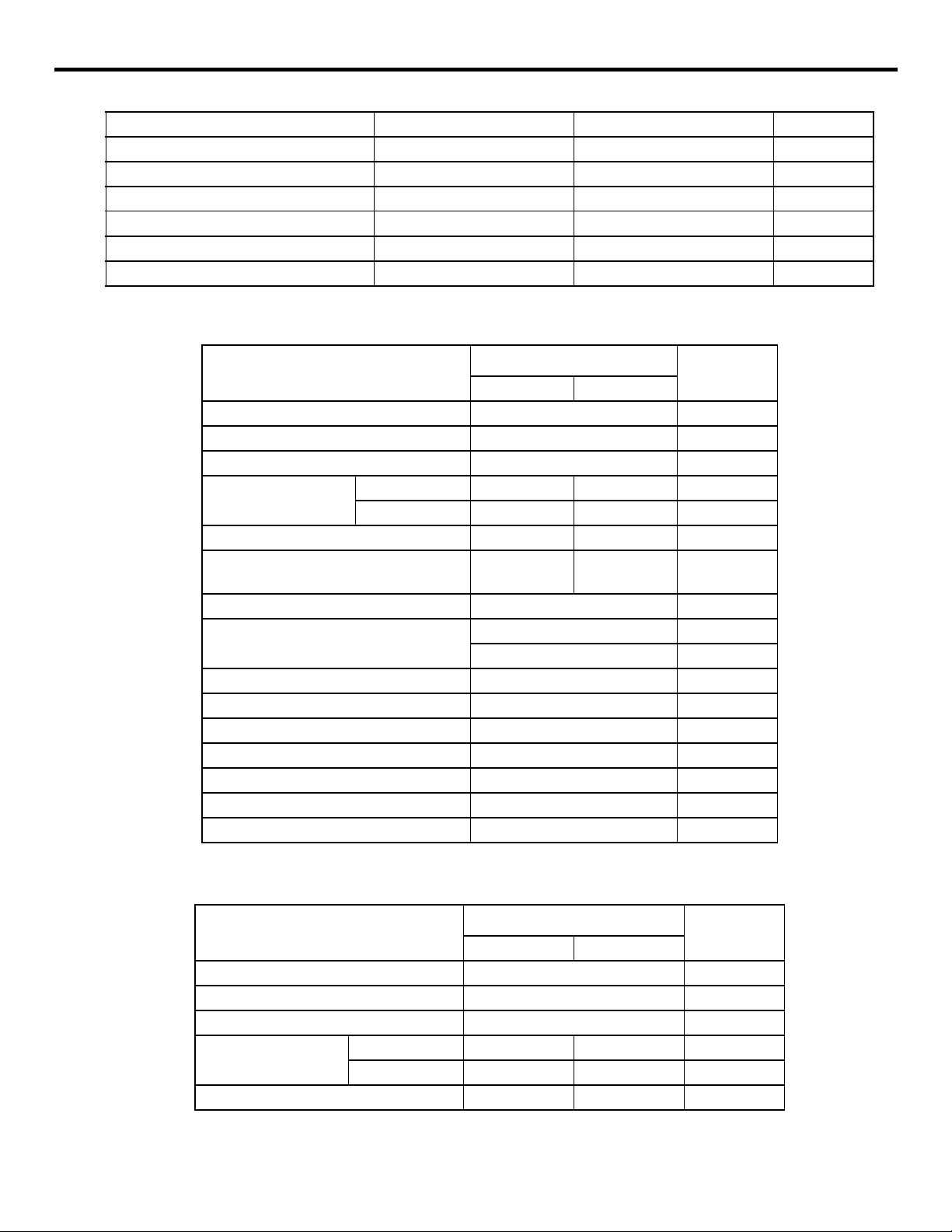
YASNAC PCNC Programming Manual Chapter 1: Programmi ng Basics
M function M 3 M3 B
Tool offset number H4 or D4 H4 or D4 B
B function B 3 B 3 O
Dwell P 63 P 63 B
Program number designation P 5 P 5 B
Sequence number designation P 4 P 4 B
Number of repetitions L 9 L 9 B
Table 1.1.3.8: Input Format (Sub Microns)
Address
Program number O5 B
Sequence number N5 B
G function G3 B
Coordinate words
Feed per minute (mm/min) F 51 F 32 B
Feed per minute (mm/min)
1/10 function
S function S 5 B
T function
M function M 3 B
T o ol of f se t number H4 or D4 B
B function B 3 O
Dwell P 63 B
Program number designation P 5 B
Sequence number designation P 4 B
Number of repetiti ons L 9 B
Linear axis a+54 a+45 B
Rotary axis b+54 b+54 O
Metric Output
Metric Input Metric Input
F 52 F 33 B
T 2 B
T 4 O
B: Basic
O: Option
Table 1.1.3.9: Input Format (Sub Sub-microns)
Address
Metric Input Metric Input
Program number O5 B
Sequence number N5 B
G function G3 B
Coordinate words
Feed per minute (mm/min) F 42 F 23 B
Linear axis a+45 a+36 B
Rotary axis b+45 b+45 O
1 - 10
Metric Output
B: Basic
O: Option
Page 18
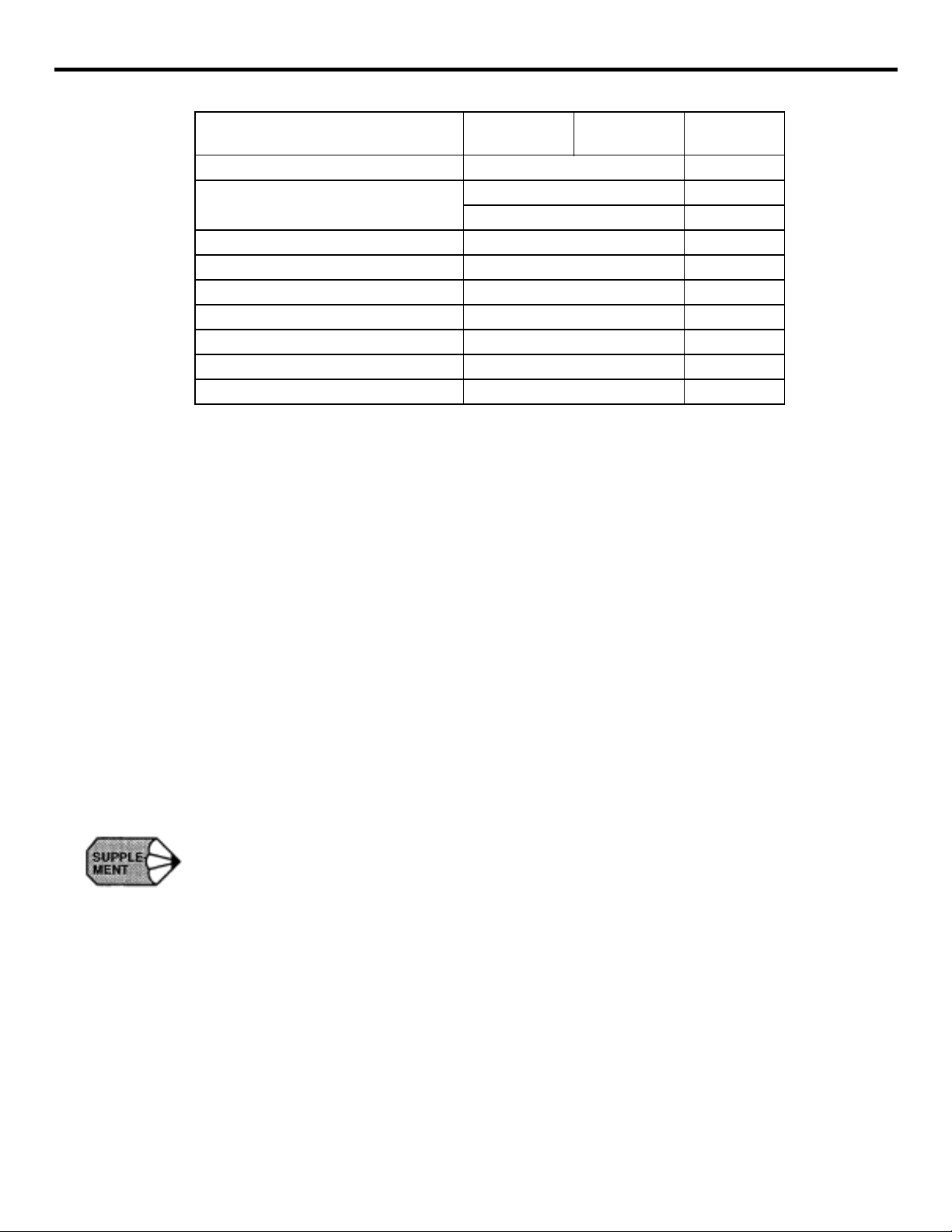
YASNAC PCNC Programming Manual Chapter 1: Programmi ng Basics
Feed per minute (mm/min)
1/10 function
S function S 5 B
T function
M function M 3 B
T o ol of f se t number H4 or D4 B
B function B 3 O
Dwell P 63 B
Program number designation P 5 B
Sequence number designation P 4 B
Number of repetiti ons L 9 B
1.1.4 Optional Block Skip (/1), (/2 to /9) *
If a block contai ning the slash code “/n (n = l to 9)” is executed with the external optional block
skip switch corresponding to the designated number set ON, the commands in the block following
the slash code to the end of bl ock code are disregarded. The slas h code “/n” can be designate d at
any position in a block.
F 43 F 24 B
T 2 B
T 4 O
Example:
/ 2 N 1234 G01X100 / 3 Y2 00;
If the “/2” switch is ON , the entire block is disrega rded, and
if “/3” switch is ON, this block indica te s the foll ow i ng.
N 1234 G01 X100;
1. “1” can be omitted for “1”.
2. The optiona l bl oc k skip function is processe d w he n a part program is read to the buffer
register fr o m either the tape or memory. If the switch i s set ON after t he bl oc k containing
the optional bloc k skip code is read, the block is not skipped.
3. The optional block skip function is disregarded for program reading (input) and punch out
(output) oper ation.
1 - 11
Page 19
YASNAC PCNC Programming Manual Chapter 1: Programmi ng Basics
1.1.5 Buffer Register and Multi-active R eg ister
By using the buffer register and multi-active register, the NC ensures smooth control of the
machine by readi ng th e bl ocks of data into the buffer regi ste r.
(1) Buffer Register
In normal operation, two blocks of data are buffered to calculate the offset and other data that
are necess ary for the succe eding operation.
In the tool radius offset C mode (op tion), two blocks of data (a maxi mu m of four blocks of
data, if necessary) are buffered to calculate the offset data that are necessary for the succeeding operation. In bot h of th e normal operatio n mo de and tool radius offset C mode, the da ta
capacity of one blo ck is a maximum of 128 cha ra ct ers, inc l uding the EOB code.
(2) Multi-active Re gi ste rs *
With a part program enclosed by M93 and M92, a maxim um of seven blocks of data ar e buffered. If the time required for automatic operatio n of these seven buffered blocks is lon g e r
than the time required for the buffering an d calculation of the offset data for the next sev en
blocks, the program ca n be executed continu ousl y w it hout a stop between blocks .
Table 1.1.5.1: M92 and M93 Codes
Linear Axis Definition
M92 Multi-active registers OFF
M93 Multi-active registers ON
1 - 12
Page 20
YASNAC PCNC Programming Manual Chapter 1: Programmi ng Basics
1.2 BASICS OF FEED FUNCTION
This sec tion desc r ibes the fe ed functio n that specifies fee dr ate (dis tance per minute, di stance pe r
revolution) of a cu tting tool.
1.2.1 Rapid Traverse
Rapid traverse is used for positioning (G00) and manual rapid traverse (RAPID) operation. In the
rapid traverse mode , each axis moves at the rapid t raverse rate set for the indivi dua l axes; the
rapid traverse rate is det ermined by the machine tool builder and set for the individual axe s by
using parameters. Since the axes move indep en dently of each other, the axes reach the ta rget
point at different time. Th ere fore, the resultan t tool pa th s are no t a straig ht l ine ge nerally.
The rapid trav erse overrid e function can adjust the set rapi d traverse rat e t o F
100% where F
indicates a fixed feedrate set for parameter pm2447.
0
1. Rapid traverse rate is set in t he following units for the individual axes.
Setting units of rapid traverse rate 1 mm/min
2. The upper limi t of the rapid traverse rate is 24 0, 000 mm/min. Since the m ost appr opriate
value is set conforming to the machine capability, refer to the manuals published by the
machine tool builder for the rapid traverse rate of your machine .
1.2.2 Cutting Feed (F Command)
The feedrate at which a cuttin g tool should be moved in the lin ea r interpolation (G0 1) m ode or
circular interpo la ti on (G 02, G03) mode is design at ed using address character F.
• With a 6-digit numeral spec i f ie d fol lowing address c haracter F, feedrate of a cutting
tool can be designated in un its of “mm/min”.
• The feedrate spec ifi ed using an F code can be m ul ti pl ie d by 1/10 by changing the set-
ting for parameter pm2004 D0. The program m able feedrate range is indicated in
Table 1.2.2.1
0.1 inch /min
1 deg./min
, 25%, 50%, and
0
Table 1.2.2.1: Programmable R ange of F C ode
Normal Mode (pm2004 DO=O) F-command 1/10 Function (pm2004 DO = l)
Input System
Format
Microns F60 F1.0-F 24000 mm/min F61 F0.1-F 24000.0 mm/min
Sub Microns F51 F0.1-F 24000.0 mm/min F52 F0.01-F 24000.00 mm/min
Sub Sub-microns F42 F0.01-F 2400.00 mm/min F43 F0.001-F 2400.000 mm/min
Inches F41 F0.1-F 9448.8 inch/min F42 F0.01-F 9448.81 mm/min
Programmable Range
(Feed per Minute)
1 - 13
Format
Programmable Range
(Feed per Minute)
Page 21
YASNAC PCNC Programming Manual Chapter 1: Programmi ng Basics
• The upper limit of feedrates indicated in T able 1.2.2.1 could be restricted by the servo
system and the mechanical system. In this cas e, the allow able upper lim it is set for
parameter (pm2800) and if a feedrat e command excee ding thi s limit va lue is speci fied,
the feedrate is clamped at the set allowable upper limit.
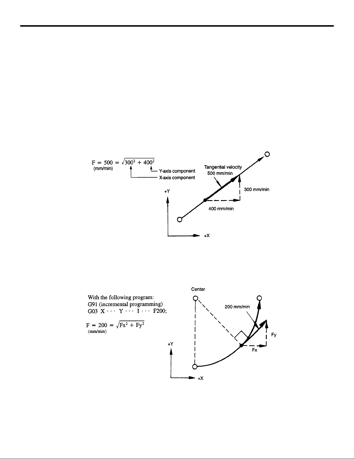
• An F command specif ied in the sim ultaneous 2-axis lin ear inter polatio n mode or in th e
curricular interpolation mode represents the feedrate in the tangential direction.
Example of Programmi ng
With the following program :
G91 (incremental programming)
G01 X40. Y30. F500;
Fig. 1.2.2.1 F command in Simultaneous 2-axis Control Linear Interpolatio n
Example of Programmi ng
Fig. 1.2.2.2 F command in the Simultane ous 2-ax is C ontrol Circular Inte rpolation
1 - 14
Page 22
YASNAC PCNC Programming Manual Chapter 1: Programmi ng Basics
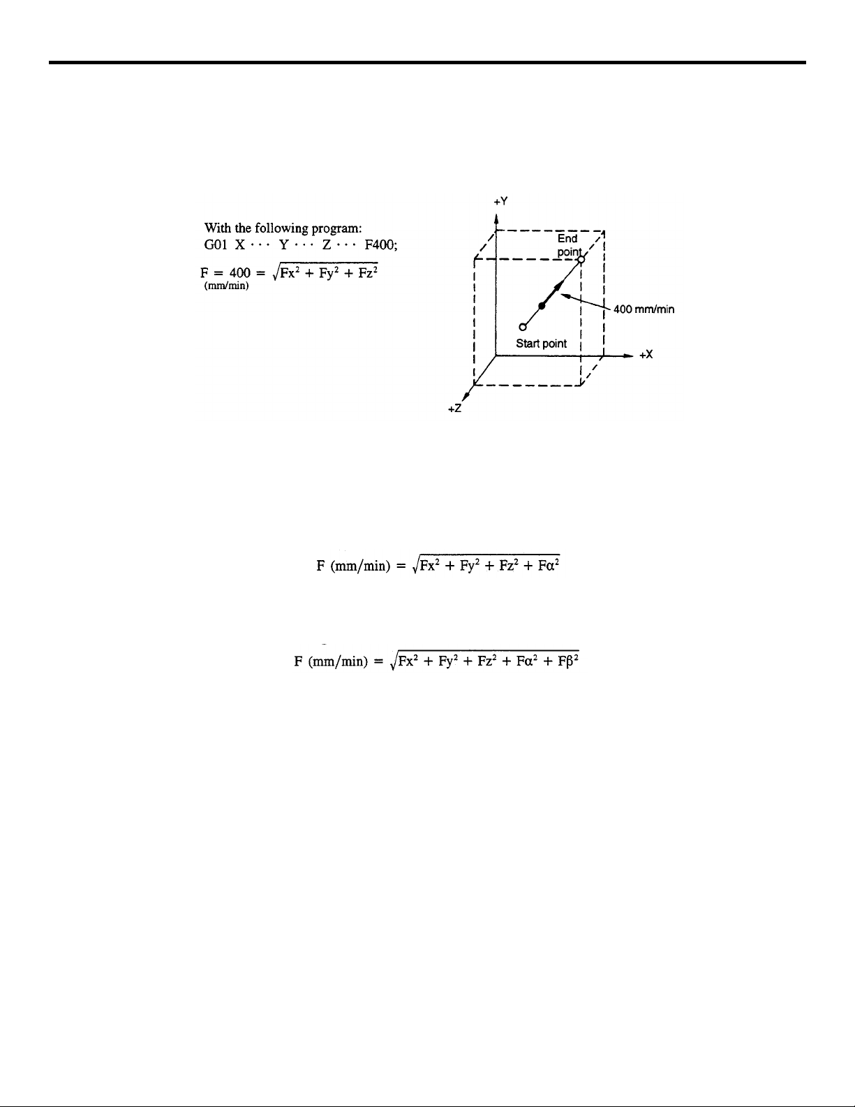
• In the simultaneous 3-axis control linear interpol ation, an F com ma n d indicates the
tangenti al f eedrate.
Example of Programmi ng
Fig. 1.2.2.3 F Command in Simultaneous 3-axis Control Linear Interpolation
• In the simultaneous 4-axis control* linear interpolation, an F command indicates the
tangenti al f eedrate.
• In the simultaneous 5-axis control* linear interpolation, an F command indicates the
tangenti al f eedrate.
1 - 15
Page 23
YASNAC PCNC Programming Manual Chapter 1: Programmi ng Basics
1. The F-command 1/10 function does n ot influence the feedrate called by an F1-digit command.
2. After changing the setting for parameter pm2004 D0, the new setting becomes valid when
the NC is reset.
3. During solid tapping, the F-command 1/10 function does not influence the feedrate called
by an F command.
4. The feed rate specified by an E code i n a canned cycle is influenced by the F-comm and 1/
10 function. The command format of an E comman d is the same as with an F command.
5. When the F-com ma nd 1/10 function is used, th e minimum unit of the syste m va ri ables
used for E and F commands is made one decimal place smaller. In metric input, if the
least increment of the F command system variable is 1 mrn/min, for example, it becomes
0.1 mm/min when the F-command 1/ 10 function is used.
6. When the F-command 1/10 function is used, designation of the macro system variables of
E and F commands and the arguments (E, F) used for calling a macro program requires
entry of a decimal fraction increa sed by one digit. In metric in put, the command of “G65
PI F1234”, for example, is ex pressed as “#9=123.4”.
7. If “F0” is specified, alarm “0370” occurs .
8. For an F command, a minus value must not be specified. If a minus valu e is spe ci fie d for
an F command, correct operation cannot be guaranteed.
1.2.3 F1-Digit Feed*
It is possible to select a feedrate by specifying a l-digit numeral (1 to 9) following address F. W i th
this manner of desi gnation of an F command, the feedrate pr ese t for the specified nume ral is
selected. The feedr ate to be sel e ct ed in response to the designa tion of F1 to F9 should be set for
the para meters in dicated in Table 1.2.3.1.
Table 1.2.3.1: Parameter Numbers Used for Presetting F1-digit Feedrates
F Command Parameter Numbers
F1 pm0820
F2 pm0821
F3 pm0822
F4 pm0823
F5 pm0824
F6 pm0825
F7 pm0826
F8 pm0827
F9 pm0828
Note: Value1= 0.1 mm/min, or 0.01 inch/min
1 - 16
Page 24
YASNAC PCNC Programming Manual Chapter 1: Programmi ng Basics
When us ing the F1-digit feed functi on, it is pos s ible to op timize the selected feedrate by turni n g
the manual pu lse gen erat or w hil e t he F1- DIG IT s wit ch is O N. I ncr eas e or decr ea se of incr em ents
per pulse (F1-digit multiply) should be set for the parameters indicated in Table 1.2.3.2.
Table 1.2.3.2: Parameter Numbers Used for Setting F1-digit Mul tiply for the para
F Command Parameter Numbers
F1 pm2111
F2 pm2112
F3 pm2113
F4 pm2114
F5 pm2115
F6 pm2116
F7 pm2117
F8 pm2118
F9 pm2119
Note: Value “1”= 0.1 mm/min per pulse
If increase/decrease increments per pulse is set for these parameters, the value set for the parameters in Table 1.31 is updated in response to the manual pulse generator op eration.
Parameters indicated in Table 1.33 are used to set the upper limits of the feedrate for F1-digit feedrate selection. If a value larger than the allowable maximum feedrate set for parameter pm28 00
is set, it is disregarde d and replaced with the value set for pm2800.
Table 1.2.3.3: Parameters pm2865 and pm2866
Parameter Numbers Description
pm2865 Allowable maximum feedrate for F1 to F4
pm2866 Allowable maximum feedrate for F5 to F9
1. When the 1-digi t nu me ra ls are set to the parameter s pm0 802 to pm0828, and pm 2004 D0
= 0, feedrate on the scre en is displayed as “0”. However, th e machine moves in units of
0.1 to 0.9mm/min or 0. 01 to 0.0 9 in ch /min.
pm2004 D0 = 0
pm2004 D0 = 1
Feedrate at the deceleration of 0.001mm or 0.0001 inch is F6.0
mm/min or F4.1 inch/min.
Feedrate at the deceleration of 0.001mm or 0.0001 inch is F6.1
mm/min or F4.2 inch/min.
2. If “F0”is specified, alarm “0370” oc curs.
1 - 17
Page 25
YASNAC PCNC Programming Manual Chapter 1: Programmi ng Basics
3. When th e D RY RUN switch is ON, feed command s are all executed a t the feedrate set fo r
the dry run operation.
4. The feed override function is in valid for the feedra te selected by the F1-digit com mand.
5. The feedrate set for the parameter is retained in memory if the power is turned OFF.
6. It is possible to designate an F1-d igi t com mand by specifying a varia ble in a macro program.
7. W ith the inch spec if ication, feedrates are set in units of inch/min. However, the allowable
maximum feedr ates can be set only in units of mm/min.
1.2.4 Feed per Minut e Fu n ction (G94)
When G94 is designated, a feedrate specified following address F is executed in units of “mm
(inch)/min”.
1.2.5 Solid Tap Mode (G93, G 94) *
The following G codes are used to indicate that tapping should be executed by using the solid tap
function.
Table 1.2.5.1: Solid Tap Mode G Codes
G code Description Group
G93 Solid tap mode 05
G94 Solid tap mode cancel 05
G93 and G94 ar e mod al G cod es. When th e po wer is tur ned ON or wh en th e NC is reset , th e G94
mode is automatically set.
(1) Solid Tap Mode (G93)
In the G93 solid tap m ode , solid tapping is execute d for the tapping cycles called by G84 or
G74. Axis feed is controlled in the “feed pe r revolution” mode. In th e sol id tap mode, only
solid tapping is allowed and no other operation is possible.
(2) Solid Tap Mode Cancel (G94)
When G94 is executed, the solid tap mode is canceled. After the cancellation of the solid tap
mode, conven tional type tapping is exe cuted in which axis feed is controlled in the “feed per
minute” mode.
1 - 18
Page 26
YASNAC PCNC Programming Manual Chapter 1: Programmi ng Basics
1.2.6 Automatic Accel er ati on and D e celeration
Automatic acc el era t ion/deceleration control is provided for ra pi d tra ve rse and cutting feed op eration, respectiv ely.
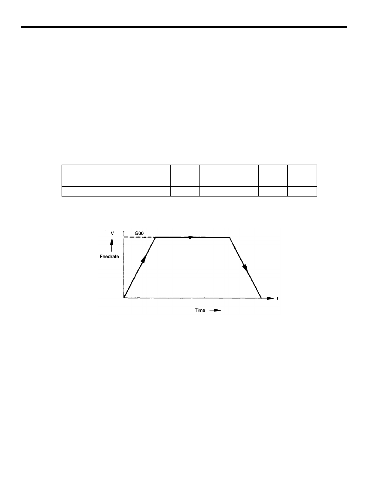
(1) Acceleration and Deceleration for Rapid Traverse and Manual Axis Feed Operation
For positioning (G00) , man ual rapid traverse (RAPID ), manual continuous feed (JOG ), and
manual handle feed (HANDLE), linear pattern auto mati c accel eratio n/dec eleratio n is appl ied.
Rapid traverse rate and acceleration/ deceleration time constant for rapid traverse are set for
following parameters.
Table 1.2.6.1: Parameters Used for Setting Ra p id Traverse Rate an d A c celeration/
Deceleration Time Constant
G code X-axis Y-axis Z-axis 4th-axis 5th-ax is
Rapid traverse rate pm2801 pm2802 pm2803 pm2804 m2805
Acceleration/deceleration time constant pm2461 pm2462 prn2463 pm2464 pm2465
Fig. 1.2.6.1 Automatic Accel er ation/Deceleration in Linear Pattern
1 - 19
Page 27
YASNAC PCNC Programming Manual Chapter 1: Programmi ng Basics
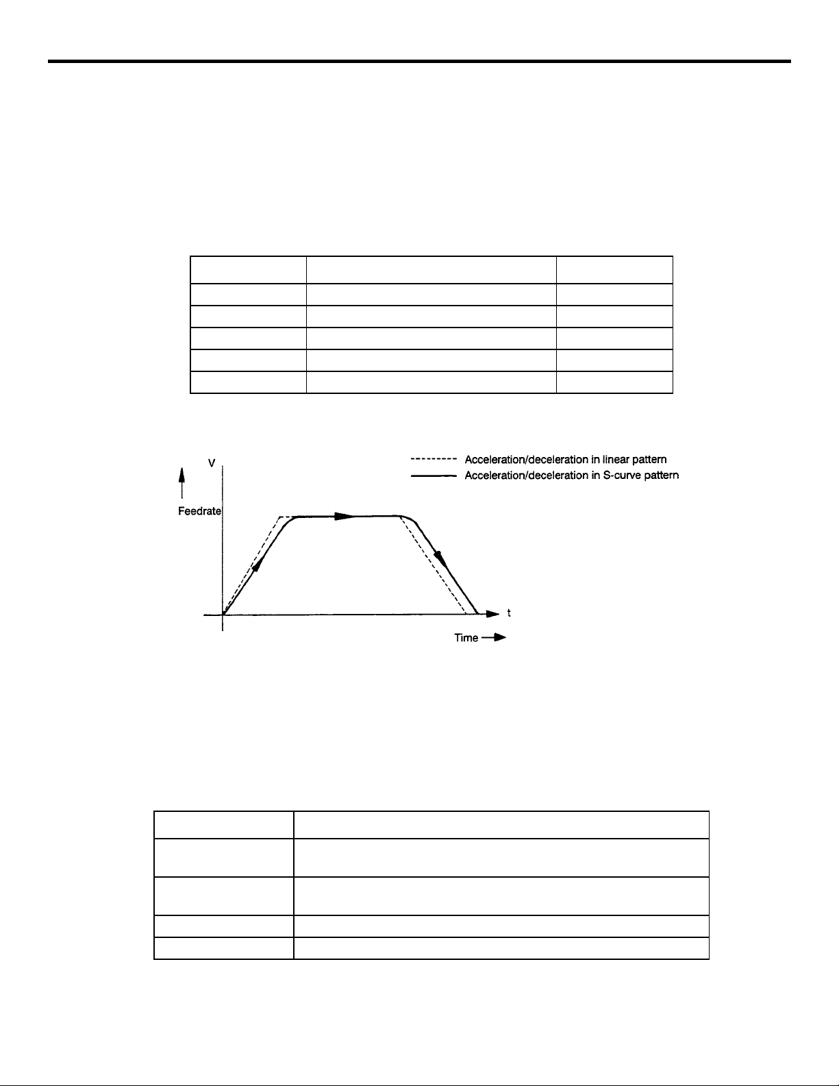
(2) Acceleration and Deceleration in S-curve Pattern *
For positioning opera ti on (G00 mode positioning), S-curve pattern can be sele cted for the
accelerat ion/deceleration patte r n instead of th e li near pattern. By us ing the S-curve pattern,
positioning is possible at a high acceleration/deceleration rate without applying shock to the
machine. The S-c urve pattern for rapid tra v erse is defined by the following parame te rs.
Table 1.2.6.2: S-curve Pattern Defining Parameters (for Rapid Traverse)
Parameter Description Setting range
pm2591 For rapid traverse of X-axis 0 to 20
pm2592 For rapid traverse of Y-axis 0 to 20
pm2593 For rapid traverse of Z-axis 0 to 20
pm2594 For rapid traverse of 4th-axis 0 to 20
pm2595 For rapid traverse of 5th-axis 0 to 20
Fig. 1.2.6.2 Acceleration/Deceleration in S-curve Pattern
For the S-curve pattern acceleration/deceleration, time constant is provided for the individual axes
and setting is possible in th e ra nge from 0 to 20.
Table 1.2.6.3: Time Constant for S-curve Pattern Control
Setting Value Explanation
0
1 to 20 (N)
Less th an 0 Regarded as “0”.
Greater than 20 Regarded as “20”.
Feedrate is controlled in the same pattern as acceleration/deceleration in
the linear pattern.
The S-curve pattern having the time constant of “4 x N” is obtained.
(Maximum time constant 60 msec) I
1 - 20
Page 28
YASNAC PCNC Programming Manual Chapter 1: Programmi ng Basics
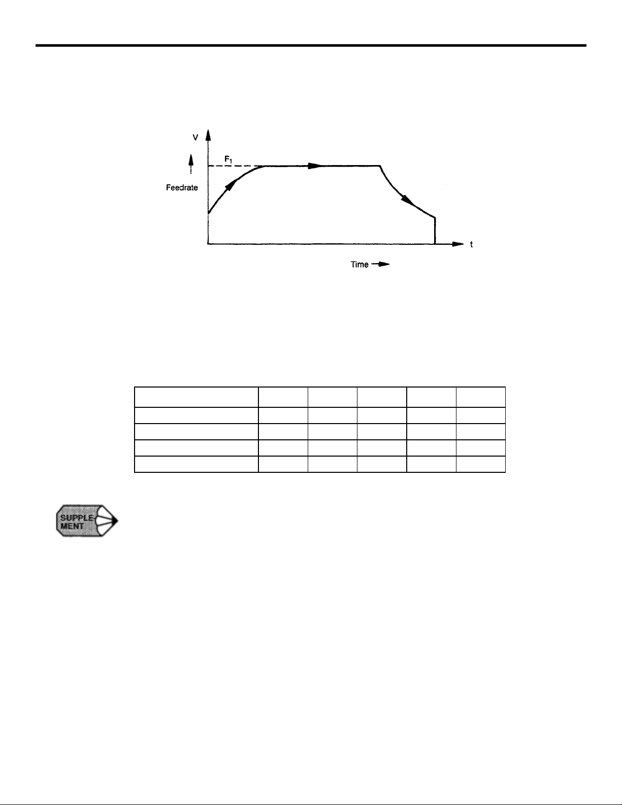
(3) Acceleration and Deceleration for Cutting Feed
For cutt ing feed (G01 to G03 mode), feedrate is co ntrolled by the au to matic acc e leratio n/
deceleration i n the exponential pat te rn.
Fig. 1.2.6.3 Acceleration/Dec el er ati on in Exponential Pattern
Time cons tant fo r cutt ing feed and f eedr ate bias a re se t fo r p aramete rs . For tappi ng, t ime con stant
and feedrate bi as can be set independ ent ly.
Table 1.2.6.4: Parameters for Tapping
G code X-axis Y-axis Z-axis 4th-axis 5th-axis
Feedrate time constant pm2501 pm2502 pm2503 pm2504 pm2505
Feedrate bias pm2821 pm2822 pm2823 pm2824 pm2825
Tapping time constant pm2511 pm2512 pm2513 pm2514 pm2515
Tapping feedrate bias pm2831 pm2832 pm2833 pm2834 pm2835
1. For the parameters i ndi cated above, the most opt imum values are set for respe ctive
machines. Do not attempt to change the setting unless necessary.
1 - 21
Page 29

YASNAC PCNC Programming Manual Chapter 2: Commands Callin g A xi s Move ments
2
Commands Calling Axis Movements
Chapter 2 describes the interp olation comman d s an d th e reference
point return commands.
2.1 INTERPOLATION COMMANDS . . . . . . . . . . . . . . . . . . . . . . . . . . . . . . . . . . . . . 2-2
2.1.1 Positioning (G00, G06, G60) . . . . . . . . . . . . . . . . . . . . . . . . . . . . . . . . . . . . 2-2
2.1.2 Linear Interpolation (G01) . . . . . . . . . . . . . . . . . . . . . . . . . . . . . . . . . . . . . . 2-4
2.1.3 Circular Interpolation (G02, G03) . . . . . . . . . . . . . . . . . . . . . . . . . . . . . . . . 2-5
2.1.4 Helical Interpolation (G02, G03)* . . . . . . . . . . . . . . . . . . . . . . . . . . . . . . . 2-11
2.2 REFERENCE POINT RETURN . . . . . . . . . . . . . . . . . . . . . . . . . . . . . . . . . . . . . . 2-13
2.2.1 Automatic Return to Reference Point ( G28) . . . . . . . . . . . . . . . . . . . . . . . 2-13
2.2.2 Reference Point Return Check (G27) . . . . . . . . . . . . . . . . . . . . . . . . . . . . 2-17
2.2.3 Return from Reference Point Return (G29) . . . . . . . . . . . . . . . . . . . . . . . . 2-18
2.2.4 Second to Fourth Reference Point Return (G30) . . . . . . . . . . . . . . . . . . . . 2-22
2 - 1
Page 30
YASNAC PCNC Programming Manual Chapter 2: Commands Callin g A xi s Move ments
2.1 INTERPOLATION COMMANDS
This section describes the positioning commands and the interpolation commands that control the
tool path along the spec ifi e d func ti ons such as straight line and arc.
2.1.1 Positioning (G00, G06, G6 0)
In the absolute programming mode (G90), the axes are moved to the specified point in a workpiece coord inate system, and in the incremental programming mode (G91), the axes move by th e
specified distance from the present position at a rapid traverse rate.
For calling the positionin g, the foll owing G codes can be used,
Table 2.1.1.1 G Codes for Positioning
G code Description Group
G00 Positioning in the error detect ON mode 01
G06 Positioning in the error detect OFF mode *
G60 Unidirectional positioning 01
(1) Positioning in the Error Detect ON Mode (G 00)
When “G00X • • • Y • • • Z • • •;” is designated, positio n ing is execut ed in the “error det ect
ON” mode, in which the program advances t o the next block only when the number of lag
pulses due to servo la g ar e checked after the completion of pulse distribution has reduced to
the permissible va lue.
In the G00 mode, positioning is made at a rapid traverse rate in the simultaneous 3- axis (*5axis) control mo de. The axes not designated in the G00 block do not m ove. In positioning
operation, the individual axes move independently of each other at a rapid traverse rate that is
set for each axis. The ra pi d tra verse rates set for the indi vidual axes differ depend ing on the
machine. For the rapid tra ve r se ra te s of your machine, refer to the ma nuals published by the
machine tool builder.
FIGURE 2.1.1.1 Positioning in Simul taneous 3-axis Control Mode
2 - 2
Page 31

YASNAC PCNC Programming Manual Chapter 2: Commands Callin g A xi s Move ments
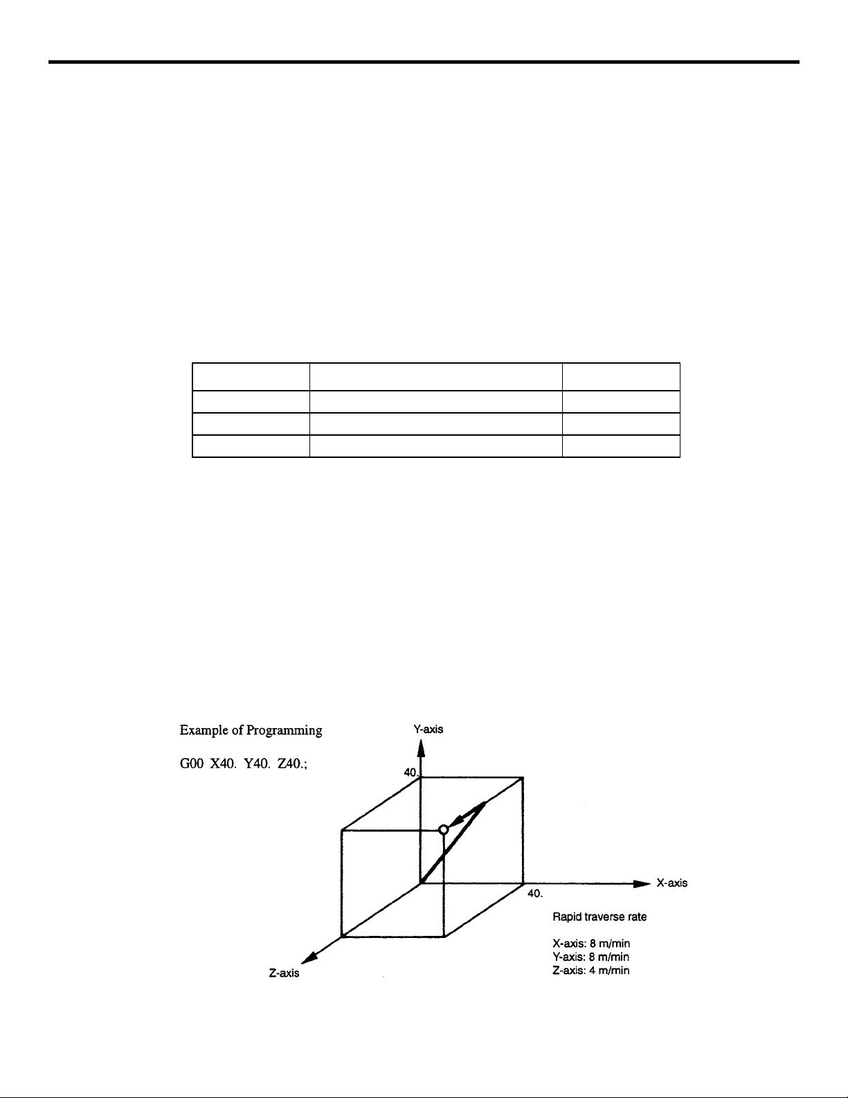
In the G00 positioning mode, since the axes move at a rapid traverse rate set for the individual
axes independe nt ly, the tool paths are not alwa ys a str ai ght line. Therefore, positioning must
be programme d ca refully so that a cutting tool will not interfere with a workpiece or fixture
during positioning.
(2) Positioning in the Er ror D e te ct O FF Mode (G06)
When “G06X • • • Y • • • Z • • • (*a • • • b • • •);” is specified, posi ti oni ng i s exe cuted in the
“error detect OFF” mode. The G06 com mand is valid only i n the designated bloc k.
In the G06 mode, program advances to the next block immediat ely after the comple ti on of
pulse distribution. The tool paths at a corner are therefore rounded.
(3) Unidirectional Positioning (G6 0) *
With the commands of “G60 X • • • Y • • • Z • • • (*a • • • b • • •);”, movement is made to the
designated position.
If positioning is made in the direction set by parameter pm4014, the axes overtravel the specified end point once a nd then return to be positioned at the end point spe ci fie d i n the G 60
block. The overtra ve l di sta nc e is set for pa rameters pm4461 to pm4465 for the individua l
axes (X-a xis to 5th -axis) . The u nidir ecti onal po siti oning mode is pro vided t o exec ute a ccurat e
positioning.
FIGURE 2.1.1.2 Unidirectional Positioning (G60)
2 - 3
Page 32

YASNAC PCNC Programming Manual Chapter 2: Commands Callin g A xi s Move ments
2.1.2 Linear Interpolation (G01)
With the commands of “G01 X • • • Y • • • Z • • • (*a • • • b • • •) F • • •;”, linear interpolati o n is
executed in the simultaneous 3-axis (*5-axis) control mode. The axes not designa ted in the G01
block do not move. For th e e xecution of the linear interpolation, t he foll ow i ng commands must
be specified.
(1) Command Format
To execute the linear interpolation, the commands indicated below must be specified.
(a) Feedrate
Feedrate is designated by an F code. The axes are controlled so that vector sum (tangential velocity in refe re nce to the tool moving di rection) of feedrat e o f the desi gna ted axes
will be the specified feedrate..
(Fx: feedrate in the X-axis direction)
If no F code is designated in the block containing G01 or in the preceding blocks, execution of
a G01 block causes alarm “0370”.
If the op t iona l 4th- a nd 5 th- axi s are rot ar y ax es (A- , B- , or C -ax is), fe edr at es o f b asi c t hre e
axes (X-, Y-, and Z-axis) and the optional 4th- and 5th-axis are determined as indicated in
Table 2.1.2.1.
Table 2 .1 .2. 1 Feedrates of Basic Three Axes an d R o tary Axes (F C o mmand)
Minimum F Command Unit
F Function
Metric Output
Inch Output
Note: If the 4th- and 5th-axis are linear axes, the feedrates of these axes are the same as the feedrates of
Metric input F60 1mm/min 1deg/min
Inch input F41 0.1 inch/min 2.54 deg/min
Metric input F60 1mm/min 0.3937 deg/min
Inch input F51 0.1 inch/min 1 deg/min
basic three axes.
Feedrate of Basic
Three Axes
Feedrate of Rotary
Axes
2 - 4
Page 33

YASNAC PCNC Programming Manual Chapter 2: Commands Callin g A xi s Move ments
(2) End Point
The end point can be specified in eit her incremental or absolute values corresponding to th e
designation of G90 or G91. (For details, see 3.2.1, “Absolute/In c rementa l P r ogrammi n g”.)
FIGURE 2.1.2.1 Linear Interpolat io n
2.1.3 Circular Interpolation (G 02, G03)
(1) Command Format
To execute the circular interpolation, the commands indicated in Table 2.1.3.1 must be specified.
Table 2.1.3. 1 Commands Necessary fo r Ci rcular Interpolatio n
Plane Designation
Direct ion of Rotation
G90
Position of End Point
G91
Distance from the Start
Point to the Center
Radius of circular arc R Radius of circular arc
Feedrate F Velocity along the circular arc
Two axes among I, J, and K
G17 Circul ar arc in the XY plane
G18 Circul ar arc in the ZX plane
G19 Circul ar arc in the YZ plane
G02 Clockwise (CW)
G03 Counterclockwise (CCW)
Two axes among X,
Y, and Z
Two axes among X,
Y, and Z
End point position in a workpiece
coordinate system
Signed distance from the star t point to
the end point
Signed distance from the star t point to
the center
2 - 5
Page 34

YASNAC PCNC Programming Manual Chapter 2: Commands Callin g A xi s Move ments
(a) Plane designation
With the commands indicated below, a cutting tool moves along the specified circular arc
in the XY plane, ZX plane, or YZ plane so that the feedrate specified by the F command
will be the tangential velocity of the arc.
• In the XY Plane
G17 G02 (or G03) X • • • Y • • • R • • • (or I • • • J • • •) F • • •;
• In the ZX Plane
G18 G02 (or G03) Z • • • X • • • R • • • (or K • • • I • • •) F • • •;
• In the YZ Plane
G19 G02 (or G03) Y • • • Z • • • R • • • (or J • • • K • • •) F • • •;
• To designate the circul ar interpolatio n mo de (G02, G03), the plane of interpolati on
should be selected first by specifying the G17, G18, or G19. For the 4th- and 5th-axis,
circular interpolation is allowed only when they are linear axes.
The G code des ignated to se le ct the plane in which circ ular interpola tion is execu ted
also select s t he plane where too l radius offset (G41/G 42) is execut ed.
When the power is turned ON, the XY plane (G17) is automatically selected.
G17 XY plane, or Xα or Xβ plane
G18 ZX plane, or Zα or Zβ plane
G19 YZ plane, or Yα or Yβ plane
• If an optional linear 4th-axis is selected, circular interpolation is possible in the Xa, Za,
or Ya plane which includes the 4th-axis in addition to the XY, YZ, and ZX planes. (a =
U, V, or W)
• Circular in te rpolation in Xa plane
G17 G02 (or G03) X • • • a • • • R • • • (or I • • • J • • •) F • • •;
• Circular interpolation in Ya plane
G18 G02 (or G03) Z • • • a • • • R • • • (or K • • • I • • •) F • • •;
• Circular interpolation in Za plane
G19 G02 (or G03) Y • • • a • • • R • • • (or J • • • K • • •) F • • •;
2 - 6
Page 35

YASNAC PCNC Programming Manual Chapter 2: Commands Callin g A xi s Move ments
• If an optional linear 5th-axis is selected, circular interpolation is possible in the Xb,
Zb, or Yb plane which includes the 5th-axis in addition to the XY, YZ, and ZX planes.
(b = U, V, or W)
• Circular in terpolation in Xb plane
G17 G02 (or G03) X • • • b • • • R • • • (or I • • • J • • •) F • • •;
• Circular interpolation in Zb plane
G18 G02 (or G03) Z • • • b • • • R • • • (or K • • • I • • •) F • • •;
• Circular in terpolation in Yab pla ne
G19 G02 (or G03) Y • • • b • • • R • • • (or J • • • K • • •) F • • •;
• If address characters which represent the 4th- and 5th-a xis are omitted as with the
commands of “G17 G02 X • • • R • • • (or I • • • J • • •) F • • •;” t he XY plane is a u t o matically selected for the interpolation plane. Circular in terpolation with the 4th- or
5th-axis is not possible if these additional axes are rotary axes.
(b) Rotation direct ion
The directio n of arc rotation should be spec ified in the manner indicated in Fig. 2.1.3.1 .
G02 Clockwise direction (CW)
G03 Counterclockwise direction (CCW)
FIGURE 2.1.3.1 Rotation Direction of Circular Arc
(c) End point
The end point ca n be specified in eithe r inc r e me ntal or absolute values corresponding to
the designation of G 90 or G91.
2 - 7
Page 36

YASNAC PCNC Programming Manual Chapter 2: Commands Calling A xi s Move ments
FIGURE 2.1.3.2 End Point of Circular Arc
2 - 8
Page 37

YASNAC PCNC Programming Manual Chapter 2: Commands Calling A xi s Move ments
If the specified end point is not on the specified arc, the arc radius is gradually changed
from the star t poin t to t he en d poin t to gener ate a sp ira l so th at th e end p oin t lies o n the
specified arc.
FIGURE 2.1.3.3 Interpolation with End Point off the Specified Arc
(d) Center of arc
The center of arc can be specified in tw o m et hods – designation of the distance from the
start point to the cente r of t he arc and designation of the radius of the arc.
• Specifying the distance from the start point to the center
Independent of th e designated dimensi oni ng mode (G90 or G91) , th e c ent e r of an a rc
must be specified in incremental values referenced from th e star t point.
• Specifying the radius
When defining an arc, it is possible to specify the radius by using address R instead of
specifyi n g the center of the arc by addresses I , J , or K. This is called “circular interpolation with R designation” mode.
• For the circular arc with the cen tral angle of 180 deg. or small er, use an R
2 - 9
Page 38

YASNAC PCNC Programming Manual Chapter 2: Commands Calling A xi s Move ments
value of “R > 0”.
• For the circula r ar c w ith the central angle of 180 deg . or larger, use an R
value of “R < 0”.
FIGURE 2.1.3.4 Circular In ter pol ation with Radius R Designation
(e) Feedrate
In the circular interpolation mo de, the feedrate can be specified in the same manner as in
the linear int erp olation mode. Re fer t o 2. 1.2 “Linear Interpolation (G 01)”.
(2) Supplements to Circular Interpolation
• A circular arc extending to multiple quadrants can be defined by the commands in a
single block. It is also possible to specify a full circle.
FIGURE 2.1.3.5 Full Circle
2 - 10
Page 39

YASNAC PCNC Programming Manual Chapter 2: Commands Calling A xi s Move ments
• With the comma n ds of “G17 G02 (or G03) I • • • J • • • F • • • Ln;”, full-c i r cl e interpo-
lation is repeat ed by n time s. If addre ss L is omitt ed , interpolation is executed once.
Execution of the commands with the single-block function ON causes full-circle interpolation to be inte rrupted after the ex ec ution of one full-circle interpolation.
• In circular interpolation, if the distance between the start and end points is smaller than
the value set for parameter pm4450, these two points are conne ct ed by a stra ight line.
2.1.4 Helical Interpolation (G02, G03)*
It is possible to execute linear interpolation in synchronization with circular interpolation with the
axis whi ch is not included in the circular interpolation p lane. This is called he lical inte rp olation.
The command form at is indicated below.
• In the XY plane
G17 G02 (or G03) X • • Y • • R • • (or I • • J • •) Z (a, b) • • F • •;
• In the ZX plane
G18 G02 (or G03) Z • • X • • R • • (or K • • I • •) Y (a, b) • • F • •;
• In the YZ plane
G19 G02 (or G03) Y • • Z • • R • • (or J • • K • •) X (a, b) • • F • •;
• In the Xa plane
G17 G02 (or G03) X • • a • • R • • (or I • • J • •) Z (b) • • F • •;
• In the Za pl ane
G18 G02 (or G03) Z• • a • • R • • (or K • • I • •) Y (b) • • F • •;
• In the Ya pl ane
G19 G02 (or G03) Y • • a • • R • • (or J • • K • • X (b ) • • F • •;
• In the Xb pla ne
G17 G02 (or G03) X • • b • • R • • (or I • • J • •) Z (a) • • F • •;
• In the Zb plane
G18 G02 (or G03) Z • • b • • R • • (or K • • I • •) Y (a) • • F • •;
• In the Yb pla ne
G19 G02 (or G03) Y • • b • • R • • (or J • • K • •) X (a) • • F • •;
Where, a an d b are the linear 4th and 5th axes respectively, each repres enting any of U - , V-, and
W-axis. If no 4th- or 5th-axis is specifie d as th e end point comma nd of t he arc, any of the command format is selecte d amo ng the commands in the XY plane, ZX pl an e, and YZ plane.
2 - 11
Page 40

YASNAC PCNC Programming Manual Chapter 2: Commands Calling A xi s Move ments
FIGURE 2.1.4.1 H elical Interpolation
1. An arc must be programmed within 360° range.
2. The feedrate spe cified with an F command indicates the tange nt ial velocity in the three
dimensional space constituted by the circular interpolatio n pl ane and the linear axis perpendicular to the interpolation plane.
3. Tool radius offset C* is valid for the axes included in the circular interpolation plane.
2 - 12
Page 41

YASNAC PCNC Programming Manual Chapter 2: Commands Calling A xi s Move ments
2.2 REFERENCE POINT RETURN
2.2.1 Automatic Return to Reference Point (G28)
With the commands of “G28 X • • • Y • • • Z • • • (*a • • • b • • •);”, the numerically controlle d
axes are re turned to the reference point. The axes are fi rs t moved to the sp ecified positi on at a
rapid traverse rate and then to the reference point automatically . This reference point return operation is poss i ble in up to simultaneo us 3-axis (* 5-axis ) control. The axes not designated in th e
G28 block are not returned to th e reference poin t.
FIGURE 2.2.1.1 Automatic Reference Point Return
(1) Reference Point Return Operation
Reference poin t return operat io n is the series of operations in which the axes retur n to the reference po int after the referen ce point return ope r ation has b een started manually.
Reference point return is a cc om pl ish ed i n two ways:
(a) Low-speed referenc e point return
In low-speed reference point return operation, a deceleration limit switch is used. In highspeed reference poi nt ret urn operation, the first return operation is executed in the lowspeed type us ing a decelera ti on limit switch; the reference point dat a are stored after the
completion o f the first reference point ret urn and in subsequent ref ere nce point return
operations is executed without using a deceleration limit switch.
2 - 13
Page 42

YASNAC PCNC Programming Manual Chapter 2: Commands Calling A xi s Move ments
(b) High-speed refere nce point return
See parameter pm 4003 D6 and D7.
It is possible to use the “high-speed reference point re tu rn ” in place of the “automatic ref-
erence point return”. In this case, the referen ce point return is executed in the follow ing
manner.
• After the positioning at the intermediate positioning point B, the axes return directly to
the reference point at a rapid traverse rate. The axes can be returned to the reference
point in a shorter tim e c om p a red to the normal refe rence point return operation that
uses a deceleration limit switch for the individual axes.
• Even if point B is loc ated outside the ar ea in w hi ch reference po int ret u rn is allowed,
the high-speed reference point retu rn specification allows the axes to return to the ref erence point.
• High-speed refere nc e point return is enabl e d only for the axes for which normal refer-
ence point return has been completed e it he r ma nually (manual refe rence point return)
or by executing th e G2 8 command after turning ON the powe r.
• If an axis for which low-sp eed refer en ce point r eturn ha s not been co mplete d either
manually or by executing the G28 command after power-ON is included in the G28
block, low-speed referenc e point return is executed for al l axes designat ed in the G28
block.
• High-speed automa ti c re ference point return is valid only when reference point return
is called by G28, a nd it does not influence manual reference po int return operation.
(2) Automatic Refe rence Point Return for Rot ary Axes
With a rotary axis, it is possible to execute the automatic reference point return the same as
with a linear axis. With a rotary axis, if it has bee n moved by more than ±360 .0 00° from the
reference point established first, reference point return is executed to the closest reference
point in the preset di rec tion of reference po int return. The illustrat ion bel ow shows how the
reference poin t re turn is executed from points A and B. (The reference point return direction
is determined by the setting for pm4002 D3 and D4.)
(Reference point return: Negative direction is selected for the reference point return direction)
(3) Supplements to the Automatic Reference Point Return Commands
(a) Tool radius offset and canned cycle
If G28 is specified in t he t ool radius offset mode (G41, G4 2) or in a ca nned cycle, alarm
“0170” occurs. G28 must not be specified in the tool radius offset mode (G41, G42) or in
a canned cycle.
(b) Tool posi ti on offset
2 - 14
Page 43

YASNAC PCNC Programming Manual Chapter 2: Commands Calling A xi s Move ments
If G28 is specified in the t ool posi ti on offset mode, positioning at the inte rm ediate positioning point is mad e wi th t he offset data va lid. However, for the positioning at the reference point, th e offset data are invalid and posit ioning is made at th e a bsolute reference
point. Whether or not the tool length offset function is disregarded after the positioning at
the referen ce point can be de termined by the setting for the parameters as indicate d b elow.
Table 2.2.1.1 G28 Command in the T ool Position Offset Mode
Parameter pm4011 Operation
D 1 = 0
D 1 = 1
Pm4010 D6 = 0: As programmed
D6 = 1: Offset valid
Pm4010 D7 = 0: As programmed
D7 = 1: Offset valid
(c) Tool length offset
It is possible to cancel the tool length offset mode by G28 by changing the setting for a parameter. If the setting is so made to cancel the tool length offset mode by the execution of G28, it
is valid only when a Z-axis command is specified with G28 in the same block. Although cancellation of the tool length offset mode is possible by G28, the tool length offset mode should
be canceled befor e th e designation of G28.
Table 2.2.1.2 Cancelin g Tool Length Offset Mode
Parameter pm4010 D7 Operation
T ool len gth off set mode is canc eled when the NC is r eset or at th e
0
1
execution of the reference point return.
The H code is cleared to “0”.
In this case, the tool length offset G code is retained.
When the NC is reset or at the execution of the reference point
return, the tool length offset mode is not canceled.
Both the H code and the tool length offset G code are retained.
(d) Mirror image
If G28 is specified while the mirror image mode (M95) is called up, reference point return
is executed in the manner indicated in Table 2.2.1.3.
Table 2.2.1.3 G28 Command in the Mi rror Im age Mode
Parameter pm4001 D7 Operation
Mirror image is applied to the intermediate positioning point.
D2 = 0
D2 = 1 Alarm “0127” occurs.
Movement to the reference point is not influenced by the mirror
image function.
2 - 15
Page 44

YASNAC PCNC Programming Manual Chapter 2: Commands Calling A xi s Move ments
(e) Machine lock intervention
Concerning machine lock intervention, there are two types of operation: turning ON the
machine lock after suspending axis movement by using the feed hold function, and turning
OFF the machine loc k after suspending ax is movement again by using the feed hold function. Table 2.2.1.4 shows how the machine oper ates according to th e machine lock intervention.
Table 2.2.1. 4 Machine Operation ac cording to Machine Lock Inte rv en tion
Machine Lock
Å
Å
ON
Å
ON
OFF
OFF
Machine Lock
OFF
Low
speed
type
High
speed
type
Low
speed
type
High
speed
type
Machine Lock Intervention
during Positioning to
Intermediate Positioning Point
Although po sitioning is continu ed
to the intermediate positioning
point (position data display only),
movement to the reference point
is not executed.
Display data are not updated,
either.
The axes move in the workpi ece
coordinate system up to the intermediate positioning point. After
that, posit ioning is execu ted at t he
reference point in the machine
coordinate system. Accordingly,
the reference point given in the
workpiece coordinate system is
offset.
However, the reference point in
the machine coordinate sy stem is
not offset.
Machine Lock Intervention during
Positioning to Reference Point
Display data are infinitely updated.
Although positioning is made at the
reference point after the detection of
the actuation of the deceleration limit
switch, this cannot be det ected due to
machine lock and, theref ore, the display data are infi nitely up dated.
In response to the machine lock intervention, the axes stops movi ng. After
that, the display data (position data in
the workpiece coordinate system) are
updated until the reference point
return is completed. (without axis
movement)
The axes move to the reference point.
Actual axis position is displayed due
to the interventi on of machine lock.
Accordingly, although the disp lay data
(position data in the workpiece coordinate system) agree with the reference
point, the axes are not located at the
reference point.
2 - 16
Page 45

YASNAC PCNC Programming Manual Chapter 2: Commands Calling A xi s Move ments
(4) Supplements to the Automatic Reference Point Return Commands
• It is possible to select valid/invalid of reference point return for each axis. If the axis
for which “reference poi nt return invalid” has been set is specified in the G28 block,
alarm “0241” occurs. Refer to parameter pm4002 D0 to D4.
• It is possible to display alarm “0411” (X-axis) to “0415” (5th-axis) if the cycl e st ar t
switch is pressed without car ryi ng out reference point retu rn for a ll axe s aft er turning
ON the power. Whether or not such al arm display should be given is de te rmined by
the setting for parameter pm4001 D6. For the axes for which the setting is “D6 = 1 (to
generate alarm )”, setting is possib le whethe r o r n ot the ref erence point retur n is n ecessary for a parameter. Refer to parameter pm4018 D0 to D4 (X-axis to 5th-axis).
•“It is poss ible to dis play alarm “0411” (X-axis) to “0415” (5th-axi s) whe n an a xi s
move command other than G28 is executed without completing reference point return
after turning ON the power. Whether or not su ch alarm display should be given is
determ ined by the setting for a param eter. Refer to par ameter pm 4 0 04 D0 to D4 (Xaxis to 5th-axis).
•“The absolute coordinate values of th e axes specified in the G28 block are saved to
memor y as the inte rmediate po s itioning point. For the axes n ot specifi ed in the G28
block, the intermediate positioning point saved in the previous reference point return
operation remains vali d.
• If M, S, T, an d/or B command is spec ified with G28 in the same block, the axes co n-
tinue moving to the reference point disr egarding whethe r or not the FIN processing is
completed before the positioning of an axis at the intermediate positioning point.
Therefore, DEN is output at the reference point.
• The deceleration limit switch position must be carefully attended to when executing
the reference point return for the first time after turning ON the power. For details,
refer to 2.4.2, “Manual Reference Point Return” of the Operating Manual.
2.2.2 Reference Point Return Chec k (G27)
This funct ion checks wh e ther the axes a re correctly ret u rned to the re ference point at the completion of the part program which is created so that the program starts and ends at the reference point
in the machine by specifying the commands of “G27 X • • • Y • • • Z • • • (*a • • • b • • •);”.
In the G27 mode, the function checks whether or not the axes positioned by the execution of these
commands in the simultaneous 3-axis (* 5-axis) control mode are located at the reference point.
For the axes not specified in this block, and not mo ved although the ax is command specified,
positio ning and check are not executed.
(1) Operation after the Check
When the position reached after the executio n of the commands in the G27 block agrees with
the reference point, the reference point return complete lamp lights. The automatic operation
is continuously executed when all of the specified a xes are positioned at the refe rence point.
If there is an axis tha t ha s n ot bee n returned to the reference point, re fere nce point return
check error (a la rm “0421” (X-axis) to “0425” (5th-axis) ) occurs and the auto matic operation
2 - 17
Page 46

YASNAC PCNC Programming Manual Chapter 2: Commands Calling A xi s Move ments
is interru pted. In this case, the cycle start lamp goes OFF.
(2) Supplements to the Referen ce Point Return Check Command and Othe r Oper ations
• If G27 is specified in the t ool offset mo de , po sit ion in g is m ade at the posi ti on di s-
placed by the offset amount and the positioning point does not agree with the reference
point. It is necessary to cance l the tool offset mode before specifying G27. No te that
the tool position offset an d tool length offset function s are not canceled by the G2 7
command.
• Check is not made if G27 is executed while the machine lock state is valid even for
one axis. For example, if an X-axis movement command is specified in the G27 block
while in the Z-axis neglect state, X-axis position is not checked.
• The mirr o r image function is v alid to the direction of axis mo v ement in t he r eference
point return operation called b y G 27. To avoid a position unma tc h error, the mirror
image function should be canceled by specifying M94 before execut ing G2 7.
2.2.3 Return from Reference Point Return (G29)
The commands of “G29 Y • • • Z • • •;” the ax es, having been returned to the reference point by
the execution of the automat ic refe re nce point return function (G28, G30), to the intermediat e
positioning point by bac k tra c ing the pat hs along which the reference point return has bee n e xecuted.
FIGURE 2.2.3.1 R eturn from Reference Point
2 - 18
Page 47

YASNAC PCNC Programming Manual Chapter 2: Commands Calling A xi s Move ments
(1) Intermediate Positioning Point
• It is not possible to speci fy the intermediate positioning point in the G 29 block. The
axes retu rn to the p revious po int at a rapi d tr averse ra te along the paths ta k en in the
return to the reference point. Note that the axes not specifie d in t he G 29 block do not
move.
• If G28 or G30 (see 2.2.4, “Second to Fourth Reference Point Return (G30)”) has been
executed several times before the execution of GJ29, point B to be set for the execution of B29 is established at the intermediate positioning point set in the last G28 or
G30 operatio n. The fo ll ow i ng program written in absol ute commands explains how
point B is set for the return operation from the re ference point.
2 - 19
Page 48

YASNAC PCNC Programming Manual Chapter 2: Commands Calling A xi s Move ments
FIGURE 2.2.3.2 Coordinate Values of Point B for G29 Operat ion
• In the following ca se s, the intermediate positioning point used for th e execution of
G29 does not agree with the intermediate positioning point specified for the execution
of G28 or G30. Therefore, do not specify such commands or attempt such operation.
• Exec u tion of the f o llowing before the execution of G29 after the completion of
G28:
Coordinate system setting (G92 or coordinate system setting operation in POS.
job)
Intervention of machine lock
Intervention of manual operation with manual absolute OFF
• Execution of G28, or G30 or G29 in a bl ock specified after the ca ncellation of the
mirror image (M94) a t a po sit io n differe nt fr om the posi tion w here the mirror
image was started.
• Executio n of G28, or M30 or M29 after the in te rve nt ion of manual operat i on w it h
the man ual absolu te OFF.
• If G29 is executed in the G91 incremental mode, it is valid for the commands in the
G29 bloc k , in which the distan ce from the interme d iate positioning p o int is specified,
and the position data of the intermediate positioning point are not influenced by this
mode.
2 - 20
Page 49

YASNAC PCNC Programming Manual Chapter 2: Commands Calling A xi s Move ments
(2) Supplements to the Return Command from the Reference Point Return
(a) Automatic reference point return
If G29 is specified without the execution of G28 or G30 after turning ON the power, alarm
“0240” occurs.
(b) Tool radius offset and canned cycle
If G29 is specified in the tool radius offset mode (G41, G42) or in a canned cycle (G 73,
G74, G76, G77, G81 to G89), alarm “0170” or “0182” occurs.
(c) Tool position offset
It is necessary to cancel the tool position offset function befor e spe cifying G28, G30, or
G29. If these G codes are exe cuted in the offset mod e, the inte r mediate p o s itioning point
B’ is also offset, causing the tool to move to point B. Note that the tool position offset and
tool length offset functions are not canceled by G29.
FIGURE 2.2.3.3 G 29 O peration Executed in the Tool Position Offset Mode
(d) Mirror image
Table 2.2.3.1 indicates how G29 is executed if it is specified in the mirror image (M95)
mode.
Table 2.2.3.1 G29 Operation Exec uted in Mirror Image Mode
Parameter pm4011 D2 Operation
0
1Alarm “0127” occurs.
Mirror image is applied to the intermediate positioning
point and the command values specified in the G29 block.
2 - 21
Page 50

YASNAC PCNC Programming Manual Chapter 2: Commands Calling A xi s Move ments
2.2.4 Second to Four th R eference Point Return (G30)
With the commands of “G30 Pn X • • • Y • • • Z (*a • • • b • • •);”, the axes are moved to P2 (second reference point ), P3 (thi rd re ference point*), or P4 (fou rth reference point*) in the sim ul taneous 3-axi s (* 5-axis) contro l mode afte r the p ositioni ng at the sp ecifie d interme diate p ositio ning
point. If “G30 P3 X30. Y50.;” “N specified, the X- and Y-axis return to the third reference point.
If “Pn” is omitted, the second reference point is selected. The axes not specified in the G30 block
do not move.
(1) Reference Point Positions
The position of ea ch reference point is det ermined in reference to the first referenc e point.
The distance from the first refe re nc e point to each of the reference points is set for the following parameters.
Table 2 .2 .4. 1 Reference Point Positions
X-axis Y-axis Z-axis 4th-axis 5th-axis
2nd reference point pm pm pm pm pm
3rd reference point pm pm prn pm pm
4th reference point pm pm pm pm pm
(2) Supplements to the 2nd to 4th Re ference Point Return Comma nds
• For the points to be considered to for th e execution of G30, refer to the supplem ents in
2.2.1, “Auto matic Return to Refer ence Point (G28)”.
• If G29 is specified after G30, positioning is made at the point specified with G29 after
passing the intermediate positioning point specified with G30. Only the coordinate value
of intermediate positi oni ng point of the axis specified with G30 is updated.
• For the execution of G30, reference point return must have been completed after powerON either manually or by the execution of G28. If an axis for which reference point return
has not been comple te d is included in the axes specified in the G30 bloc k, ala rm “0240”
occurs.
2 - 22
Page 51

YA SNAC PCNC Programming Manual Chapter 3: Movement Control Commands
3
Movement Control Commands
Chapter 3 describes the procedure used for setting and selecting the
coordinate system and the programming for controlling the movement
of a cutting tool.
3.1 SETTING THE COORDINATE SYSTEM . . . . . . . . . . . . . . . . . . . . . . . . . . . . . . 3-3
3.1.1 Selecting the Coordinate System . . . . . . . . . . . . . . . . . . . . . . . . . . . . . . . . . 3-3
3.1.2 Base Coordinate System (G92) . . . . . . . . . . . . . . . . . . . . . . . . . . . . . . . . . . 3-3
3.1.3 Workpiece Coordinate System (G54 to G59)* . . . . . . . . . . . . . . . . . . . . . . 3-5
3.1.4 Local Coordinate System (G52 Q2)* . . . . . . . . . . . . . . . . . . . . . . . . . . . . 3-12
3.1.5 Machine Coordinate System (G53) . . . . . . . . . . . . . . . . . . . . . . . . . . . . . . 3-13
3.1.6 Rotation of Coordinate System (G68, G69 )* . . . . . . . . . . . . . . . . . . . . . . 3-16
3.1.7 Plane Selection (G17, G18, G19) . . . . . . . . . . . . . . . . . . . . . . . . . . . . . . . 3-18
3.2 DETERMINING THE COORDINATE VALUE INPUT MODES . . . . . . . . . . . 3-19
3.2.1 Absolute/Incremental Designation (G90, G91) . . . . . . . . . . . . . . . . . . . . . 3-19
3.2.2 Inch/Metric Input Designation (G20, G2 1) . . . . . . . . . . . . . . . . . . . . . . . . 3-21
3.2.3 Scaling (G50, G51) * . . . . . . . . . . . . . . . . . . . . . . . . . . . . . . . . . . . . . . . . . 3-22
3.3 TIME-CONTROLLING COMMANDS . . . . . . . . . . . . . . . . . . . . . . . . . . . . . . . . 3-26
3.3.1 Dwell (G04) . . . . . . . . . . . . . . . . . . . . . . . . . . . . . . . . . . . . . . . . . . . . . . . . 3-26
3.3.2 Exact Stop (G09) . . . . . . . . . . . . . . . . . . . . . . . . . . . . . . . . . . . . . . . . . . . . 3-26
3.3.3 Exact Stop Mode (G61, G64) . . . . . . . . . . . . . . . . . . . . . . . . . . . . . . . . . . 3-26
3.4 TOOL OFFSET FUNCTIONS . . . . . . . . . . . . . . . . . . . . . . . . . . . . . . . . . . . . . . . 3-28
3.4.1 Tool Offset Data Memory . . . . . . . . . . . . . . . . . . . . . . . . . . . . . . . . . . . . . 3-28
3.4.2 Tool Length Offset (G4 3, G44, G49) . . . . . . . . . . . . . . . . . . . . . . . . . . . . 3-29
3.4.3 Tool Position Offset (G45 to G48) . . . . . . . . . . . . . . . . . . . . . . . . . . . . . . 3-32
3.4.4 Radius Offset C Function (G40, G41, G42) * . . . . . . . . . . . . . . . . . . . . . . 3-40
3 - 1
Page 52

YA SNAC PCNC Programming Manual Chapter 3: Movement Control Commands
3.4.5 3-Dimensional Tool Offset Function (G40, G41, G42)* . . . . . . . . . . . . . . 3-78
3.5 S, T, M, AND B Functions . . . . . . . . . . . . . . . . . . . . . . . . . . . . . . . . . . . . . . . . . . 3-85
3.5.1 Spindle Function (S Function) . . . . . . . . . . . . . . . . . . . . . . . . . . . . . . . . . . 3-85
3.5.2 Tool Function (T Function) . . . . . . . . . . . . . . . . . . . . . . . . . . . . . . . . . . . . 3-86
3.5.3 Miscellaneous Function (M Function) . . . . . . . . . . . . . . . . . . . . . . . . . . . . 3-87
3.5.4 Second Miscellaneous Function (B Function) * . . . . . . . . . . . . . . . . . . . . 3-89
3 - 2
Page 53

YA SNAC PCNC Programming Manual Chapter 3: Movement Control Commands
3.1 SETTING THE COORDINATE SYSTEM
3.1.1 Selecting the Coordina te System
There are fou r types of coordinate system s such as the base coordina te syste m, workpiece coor dinate system*, local coordinate system*, and machine coordinate system, and it is possible to
select the plane to be used in each of the coordinate systems.
FIGURE 3.1.1.1: Coordinate Systems
3.1.2 Base Coordinate System (G 92)
Before programming axis movement, a coordinate system must be set. When a coordinate system
is set, a single absolute coordinate system is determined and absolute move commands specified
after t h e s etting of a coor dinate system are all executed in it. The G92 command s ets the position
of the origin of a coordi nate system used for program ming.
(1) Commands
(a) Features of G92
G92 is a non-modal G code that is valid only in the specified block. In the G92 block, no
other G codes can be spec ifi ed.
3 - 3
Page 54

YA SNAC PCNC Programming Manual Chapter 3: Movement Control Commands
(b) Command Format
Wit h th e co mmands of “G92 X • • • Y • • • Z • • • (*a • • • b • • •):”, a coordinate system is
set so that the p resent tool positi on has th e absol ute co ordi nate va lues sp ecifi ed in the G92
block (X, Y, Z, a *, b *). In other words, the addresses in the G 92 block specify the distance from the point that should be set as the origin (0, 0, 0) of the coordinate system used
for programming to the present tool position. Axis movement commands can be specified
for up to three axes (* five axes) simultaneously . Note that the axes not specified the G92
block do not move.
FIGURE 3.1.2.1: Setting the Base Coo rdi nate System
(2) Supplements to the Base Coordinate System Commands
• G92 shoul d be s p e cified in the s ta te where tool o ffset ha s be en canceled .
• With the system equipped wit h an incrementa l en coder, coordinate system is es ta b-
lished when the power is turned ON so that the present tool position will be (0, 0, 0).
Therefor e, it is necessary to set the req uired coordin ate system be fore starting o peration.
• Once set, the coordinate system is not influenced by the reset operation. To reset a
coordinates system, perform any of the following operations.
• Setting “0” on the UNIVERSAL (COORD-SET) screen
• Setting “0” for the coordinat e s ystem in the MDI mode
G92 X0 Y0 20 (*a0 b0);
3 - 4
Page 55

YA SNAC PCNC Programming Manual Chapter 3: Movement Control Commands
3.1.3 Workpiece Coordinate System (G54 to G59)*
It is possible to set a workpiece coordinate system by shifting the base coordinate system. When
a G code (G54 to G59) is spe ci fi ed , shift di sta nc e c orre sponding to the specified G code is called
and the workpiece coordinate system is set by shifting the base coordinate system by the called
shift distance. Shift distance is set on the W ORK SH IRT SET screen correspon di ng to G5 4 to
G59. It is also possible to rotate a coor din at e system around the origin (0, 0, 0) by the set angle.
Table 3.1.3.1 G Codes Used to Call Workpiece Coordinate Systems
G code Description Group
G54 Shift to workpiece coordinate system 1 12
G55 Shift to workpiece coordinate system 2 12
G56 Shift to workpiece coordinate system 3 12
G57 Shift to workpiece coordinate system 4 12
G58 Shift to workpiece coordinate system 5 12
G59 Shift to workpiece coordinate system 6 12
(1) Number of Workpiece Coordinate Systems
The number of w orkpiece coordinate sy ste m sets ca n be increased optiona lly.
Table 3.1.3.2 Number of Workpiece Coordinate System Sets
Option 1 6 sets
Option 2 54 sets
Option 3 162 se ts
(2) Command Format
Table 3.1.3.3 Setting Workpiece Coordinate System
Option 1
Option 2
Option 3
G54 J1 (P1) G55 J1 (P1) G56 J1 (P1) G57 J1 (P1) G58 J1 (P1) G59 J1 (P1)
G54 J1 (P1)
-
G54 J9 (P9)
G54 J1 (P1)
-
G54 J27 (P27)
G55 J1 (P1)
-
G55 J9 (P9)
G55 J1 (P1)
-
G55 J27 (P7)
G56 J1 (P1)
-
G56 J9 (P9)
G56 J1 (P1)
-
G56 J27 (P7)
G57 J1 (P1)
-
G57 J9 (P9)
G57 J1 (P1)
-
G57 J27 (P7)
G58 J1 (P1
G58 J9 (P9)
G58 J1 (P1
G58 J27 (P7)
G59 J1 (P1)
)
-
)
-
-
G59 J9 (P9)
G59 J1 (P1)
-
G59 J27 (P7)
Note: An alarm occurs if an improper value is specified for addre ss J.
Option 1 . . . . . . . . . . . . . . . J2 or larger
Option 2 . . . . . . . . . . . . . . . J10 or larger
Option 3 . . . . . . . . . . . . . . . J28 or larger
3 - 5
Page 56

YA SNAC PCNC Programming Manual Chapter 3: Movement Control Commands
• By specif ying “G54 (G55, G56, G57, G58, or G59) J1 (J2 • • • • • • • J27)”, the subse-
quent programs are executed in th e selected workpiece coordinate system. Address P
can be used instea d of address J, by changing th e setting for the follow in g parameter.
G54”, “G54 J1”, and “G54 J0” have the same meaning.
pm4012 D7 = 0 Address J
pm4012 D7 = 1 Address P
• By specifying “G53 (or G90) G00 X • • • Y • • • Z • • • (* a • • • b • • •);”, it is possible
to specify temporary shi ft of a coordi nate system in the machine coor din ate syst em .
• By specif ying “G52;” the workpiece coordinate system selected currently is canceled
and the bas e coordinate s ys tem is called.
• If workpiece coordinate system shift dista nc e is c hanged after the workpiece coordi-
nate system is selected by the execution of G54 to G59, wheth er or not the new shift
distance is made valid without specifying G54 to G59 again can be selected by the setting for parameter (pm 40 21 D0).
(3) Rotation of Workpiece Coordinate System
By entering the address ca ll i ng rot at io n of a workpiece coordina te system in the G54 to G59
block, rot ation of the workpiece coord inate system is executed at th e sa me time when the
workpiece coordinate sy s tem is calle d.
Example of Programmi ng
G92 X0 Y0 Z0;
• ? The base coordinate system is set.
•
•
G54; (G68 X0 Y0 R • • •)
•? A workpiece coordinate system is set by G54. At the same time, the
• workpiece coord in at e syst em is rotated around (0, 0) it by the angl e
• specified following address R.
G55; (G69)
• (G68 X0 Y0 R • • •)
•? The workpi ece coordinate system set by G54 is canceled and a new
• workpiece coord in at e syst em is set according to the shift dist ance and
• rotation angle specifie d in the G 55 bl ock.
G52; (G69)
•? G52 returns the coordinate system to the one se t by G92. Rotation of a
•
coordinate system is canceled at t h e s ame time.
M30;
Note: The commands in ( ) indicate the program which uses the coordinate rotation function.
3 - 6
Page 57

YA SNAC PCNC Programming Manual Chapter 3: Movement Control Commands
FIGURE 3.1.3.1: Rotation of Workpiece Coordinate System
• If coordinate rot at io n is executed when cal li ng a workpiece coordi nate system by G54,
rotation is also applied to the intermediate positioning point when G28 or G30 is executed.
However, this is not applied to the reference point.
• The coordin at e rotation function is va li d onl y in the G17 plane.
• To ca ncel the coordina te rotation executed by G54, either specify G52 or reset the shift
distance of the calle d workpiece coordinate system to “0”, then specify G54 again.
• When the coordi na te rot at ion is executed, th e subse q uent program paths will be vari ed
depending on whether or not the intervention of reset is valid. This difference is caused by
the following two specifications.
• By the reset operation, th e present position is taken into the NC as the command
values to be re-set.
• The coordinate: rotation function generates axis move distance by applying rotation
calculation to the NC commands i n refe rence to the cent er of rotation.
If an address different from the one selected by the setting for parameter pm4012 D7 (J when
the selection is P, or P when the selection is J) is specified with G54, such an address is disregarded for the execution of G54.
(Example) pm401 2 D 7 = 1 (Se le c tion of P) (for option 2 or 3)
G54 J2 X0 Y0; ? Executed as “G54 P1 X0 Y0;
3 - 7
Page 58

YA SNAC PCNC Programming Manual Chapter 3: Movement Control Commands
(4) Workpiece Coordinate System Shift Distance
Fig. 3.1.3.2 shows how positi oni ng i s executed by setting a workpiec e co ordi nate system.
FIGURE 3.1.3.2 Workpiece Coordinate System Shift Distanc e
The shift distance of a workpiece coordinate system can be corrected by the following
three methods.
• To use a microprogra m
• To use external data input
• To use G10 command
3 - 8
Page 59

YA SNAC PCNC Programming Manual Chapter 3: Movement Control Commands
(a) Correcting workpiece coordinate system shift distance by microprogram
The workpiec e coordinate system shift dista nc e (a nd the external workp ie ce coordinate
system correction amount) can be read by entering a system variable in the right side of
the operation expression. It is possible to change these values by entering a system variable in the left side of the operation expressio n.
Example of progr amming
• #116 = #2501;
G54 (Pl ) X -axis workpiece c oo rdinate shift d is tance is entered to common variable #1
16.
• #2511 = #4;
• G54 (J2) X- axis work pie ce coordi nat e system s hift distance is clear ed and the cont ents
of local variable #4 are set. For th e corres po n dence between the syste m variables and
the workpiece c oordinate system shift dista nc es, refe r to Tables 4. 41, 4.42, and 4.43.
(b) Correcting w o rk piece co o r d inate sy s tem shift distance b y external data input
The workpiece coordinate system shift distance can be corrected by the external data input
signal.
The shift correcti on amount is added to th e pre s ent shift distances for G54 (J1) to G59
(J27) an d th e sum o f ex ter nall y inpu t s hif t co rre ctio n am ou nt a nd t he p res ent sh ift dis tan ce
is used as an ew s hift distance . In this case, the w orkpiece coordinate shift di s ta n c e is not
directly changed but the external workpiece coordin at e syst em shift distance is change d.
Workpiece coordinate system shift distance in actual operation
= External workpiece coordinate sy ste m correction amount
+ Workpiece coordinate system shift distance
Concerning the angle of rotation, the workpiece coordinate system shift distance should be
corrected directly.
(c) Correcting the workp ie ce coordinate system shift distance by programming (G10)
It is possible to correct the w orkpiece coordinate syste m shift distance by using the G10.
By specifyi n g” G10 Q2 (or L2) Pm Jn X
• • • Y • • • Z • • • (*a • • • b • • • );’’, the wo rkpiece
coordinate system shift distance of the specified workpiece coordinate system is corrected.
A combination of Pm and Jn specifies the workpiece coordinate system for which the shift
distance should be co rrected.
• The correspon de nce between a P number and G code is:
P1 = G54, P2 = G55, etc.
• Jn: Selects J1 - J27.
(Example) If “P2 J3” is specified, it is equal to “G55 J3”.
• If J is omitted or “J0” i s sp ecified , it is assumed that “J1” is s p ecified.
3 - 9
Page 60

YA SNAC PCNC Programming Manual Chapter 3: Movement Control Commands
• If an incorrect va lue is specified for “m” or “n”, alarm “0202” occurs.
(5) Supplements to Comman ds Used fo r Set ting th e Workpiece Coordinate System
• When the power is tu rne d ON, th e posi ti on wher e th e to ol is pres entl y posi tioned is set
as (0, 0, 0). For the system not eq uip pe d w it h absolute position encoders, the present
tool position is temporarily set as the origin of the coordinate system until an appropriate coordinate system is set.
• In the state where G92 (base coordinate system setting) is not specified, a workpiece
coordinate system is established in reference to the origin of the machine coordinate
system.
• In the state where G9 2 (ba s e c oordinate system setting) has been specified, a wo rk-
piece coordinate system is established in reference to the origin of the base coordinate
system.
• If G92 is spec ified in the stat e w h ere a workpie c e coordinate sy s te m has been set, the
base coordinate system is set so that the present tool position takes the coo rdi na te values specified in the G92 block. At the same time, th e work pi ece coordinate system is
defined in referenc e to the origin of the newly set base coordinate system.
• If G54 to G59 is executed in the tool length offset or tool position offset mode, present
offset is not canceled. Tool length offset or tool position offset should be can ce le d
before specifying G 54 to G59.
Example of Programmi ng
G43 Z0 H01; ? Position in workpiece coordinat e system Z 100.
G54;
G90 Z1000. ? Position in workpiece coordinate system Z1100.
Actual Z-axis movemen t di stance is 1400.
G54 shift distance Z = 300.
Offset H01 = 100.
• If G92 is speci fied while a program is executed in a workpiece coordinat e s ystem set
by G54 to G59, all workp ie ce coordinate systems (G54 to G5 9) and the base coordinate system are shi fted so that the coordinate v alues of the present position will be the
coordinate values specified in the G92 block. Therefore, G92 must not be specified in
the G54 to G59 mode.
• To change a workpiece coordinate system by G54 to G59, select the G90 mode before
calling the new coordinate system and se le ct the G 90 m ode again before returning to
the base coordinat e syst em .
• G54 to G59 must be specified in the G00 or G01 mode. If these G codes are specified
in another mode, alarm “0322” occurs.
3 - 10
Page 61

YA SNAC PCNC Programming Manual Chapter 3: Movement Control Commands
• If the workpiece coordinate system cancel (G52) is exec u ted, the coordinate system
returns to the base machine coordinate system that is used as the reference of the
workpiece coordinate system.
Note: The reference point and the origin of the machine coordinate system are the same point.
FIGURE 3.1.3.3 Cor recting the Workpiece Coordinate Syst em Shift Distance
• The machine coo rdinate system, base coordinate system, and workpi ece coordinate
systems that have been set are not influenced by the reset operation. To reset the coordinate systems that have been set, operations meeting the type of coordinate system to
be reset are require d.
• Axis move commands can be specified with the workpiece coordinate system setting
command in the same block. In this ca s e, the move commands are ex ecuted in that
workpiece coordinate system.
3 - 11
Page 62

YA SNAC PCNC Programming Manual Chapter 3: Movement Control Commands
3.1.4 Local Coordinate System (G 52 Q 2)*
The coordinate syst em established by shifting the workpiece coordinat e syste m by the spec ified
shift distance is called the local coordinate system. Once a local coordinate system is set, a cutting tool mov es in that system. A local coo rdinate system is valid only a f ter the setting of a workpiece coordin at e system. If local coordinate system setting commands are specified although a
workpiece coordinate sy s t em has not been se t, alarm “0321” occurs.
(1) Command Format
• By specif ying “G52 Q2X • • • Y • • • Z • • • (*a • • • b • • •);’’, the coordinate system
that is shift ed from the present workpiec e coordinate sys tem by the spe c ified shift distance can be set.
• By specifying “G52 Q2 X0 Y0 Z0 (* a0 b0);”, the local coordinate system is canceled
and the previousl y selected workpiec e coordinate system is recovered.
• By specif ying “G52;” independently in a block, the base coordinate system is called.
The base coordinate system is calle d w it h G 52 specified independently in a block.
FIGURE 3.1.4.1: Local Coordinate System
[Workpiece Coordinate System Shift Distance (200., 100.)]
3 - 12
Page 63

YA SNAC PCNC Programming Manual Chapter 3: Movement Control Commands
(2) Supplements to Local Coordinate System Setting Commands
• In the state where a workpiece coordinate system and local coordinate system have
been set, G92 comm and mu st not be e xe cut e d. An op era ti on to set a coordinate system at the NC operation pa ne l m ust also be avoided. Also refer to supplemen ts in dicated in “Base Coor din at e System (G92)”.
• If G52 is execu ted while this opt ional funct ion is not s ele cted , it cance ls the wor kpiece
coordinate system (G 54 t o G59).
• The local coor dinate system is cance le d by t h e re set operation.
3.1.5 Machine Coordinate System (G53)
The machine co or dinate system, specifi c to th e machine, is determined by the ex ecution of reference point return operation. It has the ori gin (0 , 0, 0) at th e reference point.
(1) Command Format
By specifying “(G90) G53 X • • • Y • • • Z • • •;”, axis move co mmands in this are execu ted in
the machine coordinate system. G53 is a non-modal G code.
FIGURE 3.1.5.1: Machine Coordinate System
3 - 13
Page 64

YA SNAC PCNC Programming Manual Chapter 3: Movement Control Commands
(2) Example of Programming
How the coordin at e systems are defined by the program created based on the machine
coordinate system is shown in Fig. 3.1.5.2.
FIGURE 3.1.5.2 Example of Program in the Machine Coordinate System (G53)
3 - 14
Page 65

YA SNAC PCNC Programming Manual Chapter 3: Movement Control Commands
(3) Supplements to the Machine coordinate System Commands
• The G53 command can be executed when all of the following conditions are satisfied.
If it is executed before all of th e m are satisfi ed, alarm “0322” occurs.
• Not in the mirror image mode
• Not in a canne d cyc l e mode or tool radius offset C mode
• The immediately preceding 01-group G code is any of G00, G01, and G 60.
• G53 and G00 are not spec ifi ed in the same block.
• If G53 is executed with machine lock ON, move command is processed to update the
present posit io n disp lay until the value to whic h th e move co mmand must be processed if ma ch in e lock were OFF, and then the processing is completed. Accor di ngly,
if machine lock ON/OFF setting is switched over while the commands in the G53
block are being exe cuted, positioning c annot be made correctly. Ho w ever, if all commands in the G53 block are executed in the machine lock OFF state, positioning can
be completed correctly even if machine lock status is switched over beforehand.
• G53 should be executed in the G90 mode. If it is executed in the G 91 mode, the commands in the G53 block are executed assuming the G90 mode.
• If G53 is executed in the tool length offset or tool position offset mode, the commands
in the G53 block are executed in a mann er to cancel the offset mode . Therefore, the
tool length offset or tool position offset mode should be canceled before specifying the
G53 comma nd.
3 - 15
Page 66

YA SNAC PCNC Programming Manual Chapter 3: Movement Control Commands
3.1.6 Rotation of Coordinate System (G68, G69)*
(1) Using the G68 and G69 Comm an ds
(a) Features of G68 and G69
For the rotation of a coordinate system, the follow in g G cod es ar e used.
Table 3.1.6.1 Coordinate System Rotation G Codes
G code Function Group
G68 Coordinate syst em rotation 18
G69 Cancel of coordinate system rotation 18
G68 and G69 are moda l G cod es belonging to 18-group. Whe n the pow e r is tu rned ON
and whe n th e NC is res et, G69 is automatically sele cted.
The G68 and G69 blocks must not include other G codes.
The coordinat e syst em rotation which is cal l ed by G68 must be cancel ed by G69.
(b) Command form at
• By specif ying “G17 (or G18, G19) G68a • • • • • b • • • • • R • • • • •;”, the commands
specified in the following blocks are rotate d by the angle specified with R around the
point (a, b). Rotation angl e can be spe cifi ed i n uni ts of 0. 001 degree.
FIGURE 3.1.6.1: Rotation of Coordinate System
• By specif ying “G69;”, the coordinate system rota ti on m ode is canceled by “G69”.
• The G68 command is executed in the plane that has been selected when the G68 com-
mand is specified. The 4th- and 5th-axis must be linear axes.
G17: XY plane or Xa, Xb pl ane
G18: ZX plane or Za, Xb plane
G19: YZ plane or Ya, Xb plane
3 - 16
Page 67

YA SNAC PCNC Programming Manual Chapter 3: Movement Control Commands
(2) Supplements to the Coor din ate Syst em Rotation Commands
• If “a” and “b” are omitted, the present position when the G68 bloc k is exec uted is
taken as the center of rotation. Note that R must not be omitted.
• When the coordi na te sy ste m is rota t ed, posi ti on data are given in the ro tate d coordinate system.
• The workpiec e coor dinate system rotation, mi rror image, and scaling fun ct io ns mu st
be specified in the predetermined order in a program. I f thi s orde r is di sr egarded,
alarm “0285” occurs.
• Workpiece coordinate > Mirror image > Scaling > Coordinate system
system rotatio n rotation
(G54) (M94) (G51 ) (G68)
• If the coordinate system rotation is executed in the mirror image mode, mirror image is
applied to the cen te r of rot at ion and also in the direction of rotation.
• If the coordinat e syst em rotation is execut ed i n the scaling mode, scaling is a pplied to
the center of rotation. In this case, however, scaling is not applied to the angle of rotation.
• The coordinate syst em rotation (G68) comma nd cannot be specified in the too l ra di us
offset C mode. If it is specified in the tool radius offset C mode, alarm “03 10” occurs.
• Usually, the coordinate system rotation is turned ON before the start of appr oach
motion an d turned OF F after the completi o n of machining. The workpiece cannot be
machined cor rectly if it is turn ed ON during machining.
• The alar m codes related to th e coordin ate system rotati o n are indicated in Table
3.1.6.2.
Table 3.1. 6 . 2 Alarm Codes
Alarm No. Description
0310
G code not allowed in
the G68 mode
0311
Format error
A G code that cannot be spe cifi ed in t he G68 mode is specifi ed.
G 68 is specified in the tool radius offset C mode.
The G68 or G69 block includes a format error.
3 - 17
Page 68

YA SNAC PCNC Programming Manual Chapter 3: Movement Control Commands
3.1.7 Plane Selection (G17, G18, G1 9)
The plane where circular interpolation, tool ra dius offset, and coordinat e syst em rotation are ex ecuted is s elected by specify ing the following G code.
Table 3.1.7.1 Plane Selection G Codes
G code Function Group
G17 XY plane 02
G18 ZX pl ane 02
G19 YZ plane 02
A plane is defined i n the fol lowing manner (in the case of X Y plane):
The horizo ntal axis in the first quadrant is “+X-axis” and the vertic al axis in the same quadrant
“+Y-axis”.
• When the power is turned ON, the XY plane (G17) is selected.
• Axis move comma nd of a sing le axis can b e specified indep endent of th e selectio n o f
plane by G 17, G18, and G 19. For example, the Z-axis can be moved by specifying “G17
Z • • •;”.
• Execution of a canned cycle is possi ble only in the G17 plane (hole machin in g axis: Zaxis).
• If the 4th-axis * is selected, the following planes are added.
G17: XY plane or Xa plane
G18: ZX plan e or Za plane
G19: YZ plane or Ya plane
• If the 5th-axis * is selected, the following planes are added.
G17: XY plane or Xb plane
G18: ZX plane of Zb plane
G19: YZ plane or Yb plane
• The plane on wh ic h the tool radius offset is exe cut e d by the G41 or G42 command is
determined by the designation of G 17, G18 or G 19; the plane that includes the rotary 4thor 5th-axis cannot be selected as the offset plane.
3 - 18
Page 69

YA SNAC PCNC Programming Manual Chapter 3: Movement Control Commands
3.2 DETERMINING THE COORDINATE VALUE INPUT MODES
This sect ion describes t he commands used to input coordinate values.
3.2.1 A bsol ute /Incremental Desi gnati on (G 90, G91)
These G co des specify whet her dimension valu es specified foll ow ing an axis addr es s are given in
an absolute value or incrementa l value.
(1) Using the G90/G91 Command
(a) Features of G90 and G91
Table 3 .2.1.1 Absol ut e/increment al D esignation G C o des
G code Function Group
G90 Absolute designation 03
G91 Incremental designation 03
• G90 and G91 are moda l G code belonging to 03-group. If G90 and G91 ar e spe ci fie d
in the same block, the one specified later is valid.
• The power-ON stat e, that is the G90 or G91 mode that is valid whe n the power is
turned ON, can be set for paramet er pm4000 D1.
pm4000 D1 = 0 Power- O N state is G90.
pm4000 D1 = 1 Power- O N state is G91.
• The reset-stat e, th at is the G90 or G91 mode that is vali d when the NC is reset, can be
set for parameter pm4000 D6.
pm4000 D6 = 0 and pm4 000 D 1 = 0: Reset-state is G90.
pm4000 D6 = 0 and pm4 000 D 1 = 1: Reset-state is G91.
pm4000 D6 = 1:The G code (G90 or G91) that was vali d be fore reset,
disregarding of the setting for pm400 0 D 1.
3 - 19
Page 70

YA SNAC PCNC Programming Manual Chapter 3: Movement Control Commands
(b) Command form at
• For the commands specified in and after the G90 block, the dimension values specified
following an address of X, Y, Z, (* a, b) are treated as absolute values.
• For the commands spec ified in and after the G91 bloc k, the di me nsi on va lues are
treated as increme ntal values.
FIGURE 3.2.1.1: Absolute/Incremental Commands (G 90, G 91)
3 - 20
Page 71

YA SNAC PCNC Programming Manual Chapter 3: Movement Control Commands
3.2.2 Inch/Metric Input Designation (G20, G21)
It is possible to select the dimension unit for the input data between “mm” and “inches”. For this
selection, the fo ll ow i ng G codes are used.
Table 3.2.2.1 Dimension Unit Selection G Codes
G code Function Group
G20 Input in “inch” system 06
G21 Input in “mm” system 06
(1) Command Format
G20 and G21 should be specifi ed at the beginning of a program in a bloc k wit hout other commands. When the G code which selects the input dimension unit is executed, the following
values are processed i n the sel ec te d di m ension unit: subsequent programs, offset amount, a
part of parameters, a part of manual operation, and display.
Example of Programmi ng
ER
CR
01234;
G20; ? Designat in g the input in “inch” system
•
•
•
(2) Supplements to the Dimension Unit Designation Commands
• A parameter is used to select “inch/mm”. Therefore, th e s tate when the power is
turned ON is de termined by the setting for this parameter.
• If the dimension unit system should be switched over durin g the exe c uti on of a pro-
gram, the followi ng processing must be accompli s hed in advance.
• If a wor k p iece coor d inate system (G54 to G 5 9) is being used, re tu rn it to the b ase
coordinate system.
• Cancel all to ol offset s (G 41 to G4 8).
• After switching over the dimension unit system between G20 and G21, the following
processing must be acco mp lished.
• Execute G92 (coordinate system setting) for all axes before specifying axis move
commands.
• If position data are displayed in a workpiece coordina te system, or when an
3 - 21
Page 72

YA SNAC PCNC Programming Manual Chapter 3: Movement Control Commands
external position data di splay unit is used, reset the present position data to “0”.
• The tool offset amou nts sto r e d in m em ory are treated in a different manner betwe en
the G20 and G21 modes.
Table 3.2.2.2 Tool Offset Amounts in G20 and G21 Modes
Sto red Of fset Amount In the G20 (Inch System) Mode In the G21 (mm System) Mode
150000 5.9055 150.000 mm
3.2.3 Scaling (G50, G51) *
The shape define d by a part program can b e en la rged or reduced accordi ng to a required scale.
For the scaling processi ng, the following G codes are used.
Table 3.2.3.1 Scaling G Codes
G code Function Group
G50 Scaling OFF 15
G51 Scaling ON 15
The G50 and G51 blocks must be spec ifi ed in the manner as indicated above without other commands entered in these bloc ks. If other commands such as other G codes and X, Y, or Z are
entered in t hese blocks , alarm “0281” occurs.
The scaling func ti on which is called by G51 must be canceled by G5 0. If G51 is specified in the
scaling mode, it is disregarded.
(1) Using the G50 and G51 Comm an ds
• By specif ying “G511 • • • J • • • K • • • P • • •;”, a program is executed on the shape
enlarged or reduced by the ratio specifie d wit h address P. The center of sca li ng is
defined by I, J, and K (representing X-axis, Y-axis and Z-axis, respectively). To
establish the present position as the center of scaling, specify “G51 I0 J0 K0 P • • •;”.
• The scaling mode can be canceled by the command of “G50;”.
• Scaling ratio can be specified in the following range.
• Scaling range: 0.0 00001 to 99.999999 tim e s
• Command unit of P is “1 = 0.000001”.
If a decimal point is used, the value of P is assumed to have six digits to the right of the
decimal point only in the G51 block.
3 - 22
Page 73

YA SNAC PCNC Programming Manual Chapter 3: Movement Control Commands
(Example)
P 0.999999‡ 0.999999 times
P 2.0 ‡ 2 times
P2 ‡ 0.000002 times
• If P is omitted, the s cale factor determ in ed by the se tting for setting paramete rs
pm0803 and pm0804 is used. It is necessary to set the scale factor within the allowable range.
Scale factor = pm0803/pm0804
(Example) If pm0803 = 3 and pm0804 = 100,
Scale factor = 3/ 100= 0.03 times
• If I, J, and/or K is specified in the G51 block, scaling is valid only for the specified
axes. Note that scaling is not possible for additional axes (4th- and 5th-axis).
• For I, J, and K in the G51 block, specify the distance fr om the origin of the workpiece
coordin at e sy stem to t he ce nt er o f scal in g if t he work pi ece co ord ina te syst em h as b een
selected.
FIGURE 3.2.3.1: Example of Programming 1
3 - 23
Page 74

YA SNAC PCNC Programming Manual Chapter 3: Movement Control Commands
FIGURE 3.2.3.2: Example of Programming 2
(2) Supplements to the G5 0 and G51 Commands
• The scal ing mode should be tu rn ed ON in the approa ch operation to start machin ing
and turned OFF after retr acting a cutting tool from the workpiece. If it is turned ON
after the start of machining, the shape cannot be machined accurately.
• Scaling is applied to the two axes in the plane for machining. If scaling is applied to
only one axis , the circular arc w il l be distorted. T h erefore, an ala r m occurs when circular int erpolation is goin g to be executed if scaling is applied to only one axis.
• If a scal e f actor greater than “1” is set, make sure that the commands after scaling will
not exceed the max imum programma bl e va lue.
• Scaling factor of “0” cannot be spec ified. If specified, ala r m “0281” occurs.
• For offset amounts, scaling is not ap pli e d.
• It is not allowed to execute a canned cycle with scaling applied to the Z-axis.
Otherwise, alarm “0280” occurs.
• The scaling mo de is can ce le d (G 50) by the reset operation (pressing the [RE-SET]
key, M02, M03, or external reset ).
• In the scaling mode, comm an d valu es an d present positi on da ta display are all pro-
cessed after scaling.
• In the scaling mode , th e fol lowing G codes cannot be specified. If specified, a la rm
“0280” occurs.
G27, G28, G29, G30, G31, G52Q2, G53, G92
• Scaling (G51) com m and cannot be specif ied in t he tool radius offset C mode.
Otherwise, alarm “0280” occurs.
• Alarm code re la t ing to the scaling func ti on are indicated i n Table 3.2.3.2.
3 - 24
Page 75

YA SNAC PCNC Programming Manual Chapter 3: Movement Control Commands
Table 3.2. 3 . 2 Alarm Codes
Alarm No. Description
0280
G code not allowed in
the scaling mode.
0281
Scaling format error
A G code that cannot be specified in the scaling mode is
specified.
• In the G50 or G51 block, a command that is not allowed
is specified.
• Scaling factor is “0”.
• A G code that is not allowed in the scaling mode is spec-
ified.
• The workpiec e coor dinate system rotation, mi rror image, and scaling fun ct io ns mu st
be specified in a predetermined ord er when they are specif ie d in the sam e bl oc k. If
this order is disregarded, alarm “0285” occurs.
Workpiece coordinate > Mirror image > Scaling > Coordinate system
system rotation rotation
(G54) (M94) (G51) (G68)
• If scaling is called in the mirror image mode, mirror image is applied to the center of
scaling.
• If coordinate system rotation is called in the scaling mode, scaling is applied to the
center of rotat ion . How e ver, scaling is not valid for the angle of rota t ion.
3 - 25
Page 76

YA SNAC PCNC Programming Manual Chapter 3: Movement Control Commands
3.3 TIME-CONTROLLING COMMANDS
3.3.1 Dwell (G04)
It is possible to suspend the execution of ax is move commands specified in the next block for the
specified len gt h of ti me (d well period).
By specif ying “G04 P • • •;”, execution of pro gra mmed commands is suspen de d for th e le ngt h of
time specified by address P.
• Command unit of address P is “1 = 0.001 see”. For exampl e, a dw ell pe r iod o f 2. 5 s econds is specified by “G04 P250 0; ”. The block used to spe cify dwell must not include
commands other than G04 and P comman ds.
• The maximum programmable val ue with address P is indicated in Table 3.3.1.1.
Table 3.3.1.1 Dwell Period (Programmable Range of P)
Format Programmable Range of Dwell Peri od (P)
P63 0 to 999999.999 sec
Note: The value is independent of the input and output unit systems.
• The timing at which the dwell should start can be selected by the setting for parameter
(pm4015 D3) from “execution when the remaining number of pulses which have been
distributed in the pr evi ous block has reduced to the al lowable limit” or “execution
immediately after the completion of pulse distribution”.
• Address X can be used inste ad of address P.
3.3.2 Exact Stop (G09)
If a block containing G09 is executed during cutting, and it calls the error detection ON mode; the
program advances to the next block in the error detection ON mode. This function is used to cut a
comer with a sharp ang le . G09 i s a non-m odal G code and valid onl y in the specified block.
3 - 26
Page 77

YA SNAC PCNC Programming Manual Chapter 3: Movement Control Commands
3.3.3 Exact Stop Mode (G61, G64)
The exact stop mode is called by G61. Once G61 is executed, the following blocks are all executed in th e error det ection O N mo de until the exact stop mode is cancele d b y G 6 4.
t
Error Detection ON Mode
In the error detection ON mode, the number of lag puls es due to servo de la y is checked after the completion
of pulse distribution in linear and circular interpolation, and the program advances to the next block only
after the number of lag pulses has been reduced to the preset value.
t
Error Detectio n OFF Mode
In the normal linear and circular interpolation, which is called in other than the G09 or G61 mode, the program advances to the next block immediately after the completion of pulse distribution, causing the comers
to be rounded due to servo lag. This operation mode is called the error detection OFF mode.
t
Error Detection ON/OFF for Rapid Traverse Operation
In rapid traverse operation, error detection ON/OFF are controlled only by G00 and G06 and the G codes
explained above are ignored.
3 - 27
Page 78

YA SNAC PCNC Programming Manual Chapter 3: Movement Control Commands
3.4 TOOL OFFSET FUNCTIONS
The following th ree kinds of tool offset function s are provided: tool lengt h offset fun ct io n, tool
position offset function (used for simplified tool radius offset), and tool radius offset C function*
(used for tool radius offset for compli ca ted shape).
1. If the tool wear offset func ti on is selected optionall y, the offset amount used in the tool
length offset function and the tool radius offset function is th e sum of the tool geometr y
offset amount and the tool wear offset amount.
2. Two types of tool offset number desig na tion methods are provided a nd w hi ch me th od
should be used can be sele ct ed by the setting for a parameter.
pm4029D0 = 0: H/D used in common
D0 = 1: H/D used for indivi dual functions
An H code is used for the tool length offset function and a D code for the tool position off-
set and tool radius of fset function s .
3.4.1 Tool Offset Data M emory
To execute the tool offset func ti ons, the tool offset amount m ust be written to the tool offset data
memory in advanc e. Depe nding on the selected speci fications, the following number of memories is available.
Table 3.4.1.1 Tool Offset Data Memory
Basic specifications 99
Addition of tool offset data memory
Addition of tool offset data memory
Addition of tool offset data memory
(option 1)
(option 2)
(option 3)
Tool Offset Data Memory
299
999
1199
3 - 28
Page 79

YA SNAC PCNC Programming Manual Chapter 3: Movement Control Commands
Table 3.4.1.2 indicates the setting range of tool offset amount.
Table 3.4.1.2 Setting Range of T ool Offset Amount
G code Linear Axis *Rotary Axis
Metric input 0 to ±999.999 mm 0 to ±999.999 deg.
Inch input 0 to ±999.999 inch 0 to ±999.999 deg.
Note: These values are not influenced by the output unit.
3.4.2 Tool Length Offset (G43, G44, G49)
The tool length offset function adds or subtracts the amount stored in the tool offset data memory
to or from the Z coordinate values specified in a program to offset the program m ed paths according to the length of a cutting tool.
(1) Commands
In the execution of th e t ool len gth offset function, addition or subtr ac tion of the offset data is
determined by the spec ified G code and the di re ction of offset by the H code.
(a) G Cod es use d for to ol lengt h offset
The tool length offset function is called by th e following G codes.
Table 3.4.2.1 G Codes Used for Tool Length Offset
G code Function Group
G43 Add 08
G44 Substract 08
G49 Cancel 08
• G43 and G44 are modal and, once executed, they remain valid until canceled by G49.
G49 cancels the tool length offset mode. H00 also cancels the tool length offset mode.
• By specif ying “G43 (or G44) Z • • • H • • •;”, tool offset amount specified by the H
code is added to or subtracted from the specified Z-axis position, and the Z-axis moves
to this offse t target position. That is, the target position of Z-axis movement specif ied
in the program is offset by the tool offset amount.
• By specif ying “(G0 1) Z • • •; G43 (or G44) H • • • 0.;”, the Z-axis moves by the dis-
tance corresponding to the tool offset amount whi ch i s spec ified by the H code.
• By speci f yi ng “G43 (or G44) Z • • • H • • •; H • • •;”, the Z- ax is moves by the distance
which is equivalent to the difference between the previous tool offset amount and the
new tool offset amount.
3 - 29
Page 80

YA SNAC PCNC Programming Manual Chapter 3: Movement Control Commands
G43, G44, and G49 can be specified only in the mode called by the G code (G00 , G01, or
G60) in 01 group. If they are specified in other modes suc h as G 02 or G03 mode, an error
occurs.
(b) H code for designating the direction of offset
The directio n of offset is de termined by the sign of to ol offset amount, specifie d by a n H
code, and a G code.
Table 3.4.2.2 Sign of Tool Offset Amount and Direction of Offset
Sign of Tool Offset Amount (H code)
Positive Negative
G43 Offs et in the positive direction Offset in the negative direction
G44 Offset in the negative direction Offset in the positive direction
FIGURE 3.4.2.1: Tool Position Offset Function
3 - 30
Page 81

YA SNAC PCNC Programming Manual Chapter 3: Movement Control Commands
(2) Supplements to the Tool Length Offset Function
• If the offset amount is changed by MDI operati on, the new offset amount bec om es
valid from the bloc k in which an H code is spec i fie d.
• It is possible to call up the tool posi ti on offset or tool radius offset C function in the
tool len g th offset mo de.
• It is not allowed to specify G43, G44, or G49 in a canned cycle mode.
• If G92 is specified with a Z command while in the tool length offset mode, the tool
length o ffset mode is c an celed. However, G92 should be s pecified in the s tate that the
tool length offset mode has been canceled.
• During automatic operation, it is possible to display the tool offset numb er (H c ode
number) that is prese ntl y va li d.
• G43, G44, and G49 can be specified only in the G00 or G01 mode. Designation of
these G codes in the G0 2 or G 03 m ode is not allowed.
• For the execution of th e reference point retu rn c ommand, including two axes, in the
tool length offset mode, whe ther the H code and the too l length offset amount should
be saved or cancele d ca n be specified by the setti ng for a parameter.
pm4010 D = 0 Both the H code and the tool length offset amount are canceled.
pm4010 D = 1 Both the H code and the tool length offset amount are saved.
• For the reset operation in the to ol length offset mode, whether the H code and the to ol
length offset amount should be saved or canceled can be specified by the setting for a
parameter. It is also possible to specify whether a G code (G49) in 08-group should be
saved o r can celed.
pm4010 D = 0 Both the H code and the tool length offset amount are canceled.
pm4010 D = 1 Both the H code and the tool length offset amount are saved.
3 - 31
Page 82

YA SNAC PCNC Programming Manual Chapter 3: Movement Control Commands
3.4.3 Tool Position Offset (G 45 to G48)
The tool position offset funct io n extends or contracts axi s mov em ent distance specifie d in a program by the distanc e set in th e t ool offset dat a me mo ry, and is primarily used for compensating
for the tool radius when cutting a square shape. It is not ne cessary to use this function if the
optional tool radius offset C functio n (G 40, G41, G42) is selected.
(1) Commands
In the execution of the tool position offset function, extension or contraction of axis movement distance is determined by the specified H code and the dir ec ti on of offset by the D code.
(a) G Codes used with the tool position offset function
Table 3.4.3.1 G Codes Used with the Tool Position Offset Function
G code Description Group
G45 Extension/Contraction *
G46 Contraction/Extension *
G47 Double-extension/Double-contraction *
G48 Double-contraction/Double-extension *
• G45 to G48 extends or contracts axis move distance specified in the bloc k th at con-
tains G45 to G48 in the direction of axis movement. Extension or contraction is valid
only for the axis move distance specified with G 45 to G4 8 and in other blocks, the
axes move as programmed. Therefore, to return the axis with which position has been
offset by the execution of G45 to G48 to the programmed position, it is nec essary to
execute G45 to G 48 that extends or contra cts the axis move distance in the opposite
direction.
• T o use the tool position offset function, the program must be written in the incremental
mode (G91). If it is written in the absolute mode (G90), the function extends or contracts the distance (i ncremental value ) from the end point reached in the block prece ding the offset block to the target point spe ci fi ed in absolute values in the offset block
along the axis move direction.
• To execute the tool posit i on offset fun ct ion, specify a G code cal ling up the tool posi-
tion offset function (G4 5 to G 48), axis address and th e tool offset data memory num ber by using a D code in th e sam e block. If a D code is used to selec t th e tool radius
offset data, it can be omitted since D code is modal. Store the radius of a cutt ing too l
in the tool offset data memory.
3 - 32
Page 83

YA SNAC PCNC Programming Manual Chapter 3: Movement Control Commands
FIGURE 3.4.3.1: Tool Position Offset Function
(b) G code for specifying the direction of offset
Whether the tool position offset is processed in extension or c ontraction is determ in ed by
the sign of the tool offset amount specified by a D code and the G code specified to call up
the tool position offset function as indicated in the table below.
However, the tool offset amount to be used in the G45 to G48 function should be stored
with the positive sign.
Table 3.4.3.2 Sign Assigned to Tool Offset Data
Sign of Tool Offset Amount (H code)
Positive Negative
G45 Extension Contraction
G46 Contraction Extension
G47 Double-extension Double-contraction
G48 Double-contraction Double-extension
3 - 33
Page 84

YA SNAC PCNC Programming Manual Chapter 3: Movement Control Commands
(2) Example of Programming
(a) Extension and contraction amounts
The relationship between the axis move distance specified in a program and the actual tool
move dist ance is given belo w. The axis move dist ance sp ecifie d in an in cremen tal va lue is
extended or contracted by one time or two times the specifie d tool offset amount.
FIGURE 3.4.3.2: Extension and Contraction of Progra mmed Tool Mov e Dist ance
(b) Execution of ex te nsi on/ contraction from offset sta rt point
If a program block is executed in the state where the start point of that block is offset by
the execution of extension or contraction in the preceding blo ck, although the tota l axis
move distance is equal to the axis mov e distance specified in a program, the axis moves
the specified distance starting from the offset start point
FIGURE 3.4.3.3 Execution of Commands from Offset Start Point
(c) Reversed axis movement direction due to execution of function
If the specif i ed tool offset amount is larger than the axis move dis t ance specifi e d in a program, axis movement direction might be reversed as the result of extension or contraction.
If this occu rs, the axis moves in the di re ction opposite to the direction specified in the pr o-
3 - 34
Page 85

YA SNAC PCNC Programming Manual Chapter 3: Movement Control Commands
gram.
FIGURE 3.4.3.4 Reversed Ax is M ovement Direction
(d) 1, J, and/or Kin G45 to G48 blocks
If I, J, and K are specified in the G45 to G48 block, each of these addresses calls up extension or contraction processing in the same direction as X-, Y-, and Z-a xi s , respe ct ivel y.
Therefore, to ol ra dius offset is possible only for a one-quarter (1/4) circ le, th re e-quarter
(3/4) circle, or a full (4/4) circle. Note that a half-circle should be defined by combining
two one-quarter (1/4) circles. In practical operation, the offset should be applied from the
block preceding the circular interpolation block to obtain the arc correctly offset. See Fig.
3.4.3.6 below.
FIGURE 3.4.3.5 Tool Radius Offset for a 1/4 Circle
3 - 35
Page 86

YA SNAC PCNC Programming Manual Chapter 3: Movement Control Commands
FIGURE 3.4.3.6 O ffse t Ap pli ed from the Precedi n g Bl oc k
(e) Canceling G45 to G48 by G2 8 (or G30)
Note 1: Although offset is applied to the intermediate positioning point specified in N4, the machine
origin is not offset.
2: Axis movement specified in N5 is executed in the following manner according to the setting
for pm4010.
Offset cancel is selectedbypm4010: Movement to P1
Offset not cancel is selected by pm401C: Movement to P2
FIGURE 3.4.3.7 Canceling G45 to G48 by G28 (G30)
3 - 36
Page 87

YA SNAC PCNC Programming Manual Chapter 3: Movement Control Commands
(f) Canceling G45 t o G 48 by G92
Note: Axis movement specified in N5 is executed in the following manner according to the setting for
pm4010.
Offset cancel is selected by pm4010: Movement to P1
Offset not-cancel is selected by pm4010: Movement to P2
FIGURE 3.4.3.8 Canc el ing G45 to G48 by G92
(3) Supplements to the Tool Offset Function
• In a G45 to G48 block, only a G code in 01-group (G00, G01, G02, G03, G60) can be
specified with G45 to G48. If a G code in other groups is specified, alarm “0365”
occurs.
• T o move an axis only by the offset amount in the incremental mode (G91), specify “0”
for the axis address. In this case, axis movement direct ion cannot be reversed even if
“0” is preceded by a sign.
• Example of Programming 1
G91 G01 G45 X0 Y0 D10 F
• • •;
Both the X- and Y-axis move in the positive direct ion b y th e offset a mount called
up by D10.
• Example of Pro gramming 2
G91 G00 G46 X0 D11;
The X-axis mo ves in the negative direction by the offset amount called up by D1l.
• For the designation of an offset number in the tool position offset mode (G45 to G48),
either H or D code can be used. Which address c h aracters should be used ca n be
3 - 37
Page 88

YA SNAC PCNC Programming Manual Chapter 3: Movement Control Commands
selected by the set tin g for a parameter.
pm4011 D1 = 1 Only H codes are valid.
pm4011 D1 = 0 Only D codes are valid.
• If G45 to G48 is specified for simultaneous two-axis movement commands, the ax is
move distance is extended or contract ed for both axes. Therefore, if the tool position
offset function is used in such a manner, the workpiece may be cut excessively or an
uncut portion may be le ft.
FIGURE 3.4.3.9 Cal li ng G 45 to G 48 Mode for Simultaneo us Two-axis Operation
• If an offset amount is changed by using the switches on the NC operation panel, the
offset amount presently called is not change d im mediately. The new offset amount
becomes vali d w hen G45 to G48 is exec ut ed next.
• The tool position offset fun ct io n can be called up in the tool le ngt h offset m ode .
• The mirror ima ge f unc ti on can be called up in the tool position offset mode . In other
words, mirror image machining is po s sible using the offset tool pat h s.
• The tool position offset function can be executed independent of the plane selection G
code (G17, G18, G19).
• It is not allowed to call up the too l posi tion offset function (G54 to G58) in a canned
cycle mode. If G54 to G58 is sp ecified in th e canned cycl e mode, alarm “0170”
occurs.
• If G92 is specified in the offset mode, the coordinate system is set after canceling the
offset for the axes specified in the G92 block. The axes should be returned to the position not including offset by executing extension or contraction commands in the direction opposite to the presently offset directi on be fore specifying G92 . Th e axis move
commands give n in the next block are exe c uted in the following ma nne r according to
the setting for parameters.
3 - 38
Page 89

YA SNAC PCNC Programming Manual Chapter 3: Movement Control Commands
When paramete r pm4011 D1 = 0:
pm4010 D6 = 0 Moves as programmed.
pm4010 D6 = 1 Offset applied.
When paramete r pm4011 D1 = 1
pm4010 D7 = 0 Moves as programmed.
pm4010 D7 = 1 Offset applied.
FIGURE 3.4.3.1 0 Exa mpl e of P rogramming 1
FIGURE 3.4.3.1 1Example of Programming 2
3 - 39
Page 90

YA SNAC PCNC Programming Manual Chapter 3: Movement Control Commands
3.4.4 Radius Offset C Function (G40, G41, G42) *
The tool radius offset function automatically offsets the programmed tool paths by specifying the
radius of the cutting tool to be used. The distance t o be offs et (radius of cutting tool) can be
stored to th e tool offset data memory by using the switches on the NC operation panel. In a program, the offset data are ca lled up by specifying the nu mber of the tool offset data memo ry usi ng
a D code.
(1) Commands
To ca ll up th e tool radius offset C function, the fol lowing G codes are used.
Table 3.4.4.1 G Codes Used to Call Up the Tool Radius Offset C Function
G code Function Group
G40 Tool radius offset C mod e cancel 07
G41 Tool radius offset C (offset to the left) 07
G42 Tool radius offset C (offset to the right) 07
The tool radius offset C function is called up by the execution of G41 or G42 and canceled
by G40. Direction of offset is det e rmined by the designated G code (G41, G42) and the
offset amount is selected by the D code which is specified with the G code designated to
call up the tool radi us offset mo de. When the power is turned ON, the G40 mode is set.
FIGURE 3.4.4.1: Tool Radius Offset C
• If a negative value is set in the tool offset data memory specified by the D code, the
offset direction is reversed. The D cod e m ust be spec i fie d w ith G 41 or G42 in the
same block or in a preceding block. If D00 is specified, it specifies the tool radius of
“0”.
• The tool radius offset plane is selected by the designation of G17, G18, orG19. The G
code used to selec t th e pl ane must be specified with G41 or G42 in the same bloc k or
in a block preceding the G41 or G42 block .
3 - 40
Page 91

YA SNAC PCNC Programming Manual Chapter 3: Movement Control Commands
Table 3.4.4.2 Plane Selection G Codes
G code Function Group
G17 XY plane selection 02
G18 ZX plane selection 02
G19 YZ plane selection 02
• It is not allo wed to chan ge t he sel ected plan e i n the o f f set mode. If a pl ane se le ctio n G
code is specified in the offs et mode, alarm “’0183” occurs.
• The tool radius offset C function is not val id for the 4th- and 5th-axis. These axes are
treated as an axis not in the selected offset plane.
(2) Entering the Offset Mode
There are two types of offset mode entry me th ods (t ypes A and B) and which met hod
should be used can be sele ct ed by the setting for a parameter.
pm4012 D6 = 0 Type A
pm4012 D6 = 1 Type B
(a) Type A: pm4012 D6 = 0
Start-up motion (axis move ments for the start-up of offset) is not executed if there are no
axis movement commands in the G 41 or G42 block.
• Start- up motion is executed when an axis move command is specified.
• If there are no move commands of the axes in the offset plane in the block next to the
G41 or G42 block, one more block is buffered to e xecute the start-up mo ti on.
• In the offset mode, spec i f ic at ion of up to two consec uti ve blocks that do not contain
axis move (comm ands in the offset plane is all ow e d. However, if no axis move command in the of fs et plan e is speci fie d in three o r more co nsecut ive bl ocks , off set mot ion
is interrupted and th e offset block is not generated.
(b) Type B: pm4012 D6 = 1
Start-up motion (axis movem e nt s for the star t-up of offset) is executed even when an axis
move command is no t speci fi ed i n the G41 or G42 block.
• In response to the designation of G41 or G42, the cutting tool mov es to the posi ti on
offset by the radius. The offset is made to the left or right side in reference to the tool
advancing direction and in the normal direction at the start point of the next block.
• If there are no axis m ove commands in the offset pl ane in the G41 or G42 block, the
axes move by the offset am ount.
• If there are no move commands of the axes in the offset plane in the block next to the
G41 or G42 block, one more block is buffered to e xecute the start-up mo ti on.
• In the offset mode, spec i f ic at ion of up to two consec uti ve blocks that do not contain
3 - 41
Page 92

YA SNAC PCNC Programming Manual Chapter 3: Movement Control Commands
axis move commands in the offset plane is allowed. If no axis move commands in the
(off s e t plane are specified in three or more consecutiv e b l o cks, tool radi u s offset start s
from the next block that contains axis move comman ds.
(3) Start-up of Offset
Since the offset start-up is executed with the offset taken into account, the G code in 01-group
must be either G00 or G 01. If a G code other than G00 or G01 is specified, alarm “0180”
occurs. If th e offse t s ta rts in the G00 mode, the axes move to the offset point at their individual rapid t ra ver se rat es. Th eref or e, be awar e of poss ibl e inte r feren ce of a cutti ng to ol w ith th e
workpiece. There are two types of start-up such as start-up at inside corner and start-up at outside comer.
(a) Start- up at inside corner (180 ° or less)
The cuttin g t o ol mov es to the offset point (on the normal start point of the vector of movement called up in the blo ck ne xt to th e sta rt - up block).
• From straight-line to straight-l ine
Note: “S” indicates the single-block stop point.
FIGURE 3.4.4.2 Offset Start-up (Straight-Line to Straight-Line)
3 - 42
Page 93

YA SNAC PCNC Programming Manual Chapter 3: Movement Control Commands
• From straight-line to arc
FIGURE 3.4.4.3 Offset Start-up (S traight Line to Arc)
(b) Start-up at outside corner (180° or larger)
In this case, two kinds of start-up modes (types A and B) are provided and the mode to be
used can be selecte d by th e setting for a parameter.
pm4013 D0 = 1 Type A
pm4013 D0 = 0 Type B
• Type A : pm4013 D0 = 1
The cutting tool moves to the offset point (on the normal start point of the vector of the
block next to the start-u p bl ock).
• From straight-line to strai ght li ne at ou tsi de c orner (180° to 270°)
FIGURE 3. 4 . 4.4 Offset Start-up (Straight-line to S traight-line (1))
3 - 43
Page 94

YA SNAC PCNC Programming Manual Chapter 3: Movement Control Commands
• Straight- line to Straight-lin e at ou tside comer (270° to 360°)
FIGURE 3. 4 . 4.5 Offset Start-up (Straight-line to S traight-line (2))
• Straight-line to ar c at outside corner (18 0° t o 270°)
FIGURE 3.4.4.6 Offset Start-up (Straight-line to Arc (1))
3 - 44
Page 95

YA SNAC PCNC Programming Manual Chapter 3: Movement Control Commands
• Straight-line to str aight-line at outside comer (180° to 270°)
FIGURE 3.4.4.7 Offset Start-up (Straight-line to Arc (2))
• Type B: pm4013 D0 = 0
The cutting to ol moves to the p ositi on obt aine d by the ca lc ulat ion fo r point of inte rsection using the commands in t he start -up block and the next block.
• Straight-line to str aight-line at outside corner (180° to 270°)
FIGURE 3. 4 . 4.8 Offset Start-up (Straight-line to S traight-line (1))
3 - 45
Page 96

YA SNAC PCNC Programming Manual Chapter 3: Movement Control Commands
• Straight-line to str aight-line at outside corner (270° to 360°) ;
FIGURE 3. 4 . 4.9 Offset Start-up (Straight-line to S traight-line (2))
• Straight-line to ar c at outside corner (18 0° t o 270°)
FIGURE 3.4.4.10Offset Start-up (Straight-line to Arc (1))
3 - 46
Page 97

YA SNAC PCNC Programming Manual Chapter 3: Movement Control Commands
• Straight-line to ar c at outside corner (27 0° t o 360°)
FIGURE 3.4.4.11Offset Start-up (Straight-line to Arc (2))
(4) Axis Movements in the Offset Mode
Once the tool radius offset mode is set by the execution of G41 or G42, the cutting tool moves
along the paths offset from the programmed paths until the tool radius offset mode is canceled
by G40. Since the offset paths are automatically generated by the NC, the program should
simply define the shape to be machined. The tool paths are controlled according to the angle
made be tween the specified programmed pa ths.
(a) Inside corner (smaller than 180°)
The cutting tool m oves to the position obtained by the calculate on for the poi nt of int ersection.
• Straight-line to straight-line
FIGURE 3.4.4.1 2Straight-line to Straight-line
3 - 47
Page 98

YA SNAC PCNC Programming Manual Chapter 3: Movement Control Commands
• Straight-line to Arc
FIGURE 3.4.4.1 3Straight-line to Arc
• Arc to arc
FIGURE 3.4.4.14Arc to Arc
(b) Outside corner (larger than 180°)
For this offset, two types of offset modes are prov id ed a nd the offset mode to be used can
be selected by the designa tion of a n M code.
M96 Tool radius offset round-the-arc ON
M97
Tool radius offset round-the-arc OFF
(calculati on is executed to obtain the point of intersection)
• Tool mo vements in the M96 (tool radius offset rou nd-the-arc ON) mode
• Straight-line to straight-line
Note: In this case, round-the-arc motion of a cutting tool is included in the preceding block.
FIGURE 3.4.4.15Round-the-arc Motion (Str aight-line to S traight-line)
3 - 48
Page 99

YA SNAC PCNC Programming Manual Chapter 3: Movement Control Commands
• Straight-line to arc
FIGURE 3.4.4.16Round-the-arc Motion (Straight-line to Arc)
• Arc to arc
FIGURE 3.4.4.17Round-the-arc Motion (Arc to Arc)
• Tool mo ve ments in the M97 (tool radius offset round- the-a rc O FF) mode
• Straight-line to str aight-line at outside corner (180° to 270° )
FIGURE 3.4.4.18Offset Motion (Straight-line to Straight-line)
3 - 49
Page 100

YA SNAC PCNC Programming Manual Chapter 3: Movement Control Commands
. Straight-line to arc at outside corner (180° to 270°)
FIGURE 3.4.4.19Offset Motion (Straight-line to Arc)
• Arc to arc at outs ide comer (180° to 270°)
FIGURE 3.4.4.20Offset Motion (Arc to Arc)
• Straight-line to str aight-line at outside corner (270° to 360°)
FIGURE 3.4.4.21Offset Motion (Straight-line to Straight-line)
3 - 50
 Loading...