

Page 1

YASNAC PC NC
Connecting Manual
Version: Beta 1.0
Page 2
YASNAC PCNC Connecting Manual Preface/Table of Contents
SAFETY INFORMATION
PRECAUTIONS
1. Read this instruct io n ma nual in its entirety before using the YASNAC PC N C Connecting Manu al .
2. The following warning symbols are used to indicate precautions that the user must be aware of
to safely use this equipment. Failure to follo w thes e pre cautions can result in serious or possibl y
even fatal injury and damage to products or related equipment or system.
WARNING
WARNING
WARNING
This sym b ol indica tes the pre s en ce of a potentially hazardous condition which, if not avoided,
could result in serious personal injury or death.
This precau tionary symbol appear s in la be ls attached to YA SN AC products to alert th e use r to
conditions requiring concern for safety.
SPECIAL SAFE TY N O TE: This symbol indicates that ELECTRICAL SHOCK HAZARD
condition exi s ts. D O N O T TO U CH a ny electrical connection termin al s w hen the power is ON,
and for at least 5 minutes after switching off the power supply.
CAUTION
This symbol indicates the presence of a potentially hazardous condition which, if not avoided,
could result in mino r or moderate personal in jury and/or damage to eq uipment.
NOTICE
Printed _______. 1999. The information contained within this document is the proprietary property of
Yasakawa Electric America, Inc., and may not be copied, reproduced or transmitted to other parties without
the expressed wr itte n authorization of Yasakawa Electric Americ a, Inc.
No pattent liabil ity is assumed with respect to the uses o f the information con tained herein. Mo r eover,
because Yaskawa is constant ly im proving its high quali ty product, the informa ti on contained in this ma nual
is subject to chan ge w ithout notice. Every precaution has been taken in th e preparation of this document.
Nevertheless, Yasakawa assumes no responsibilit y for da m ag es resu ltin g from th e use of the inf orm a tion
contained within this publication.
i
Page 3

YASNAC PCNC Connecting Manual Preface/Table of Contents
Table of Contents
1. GENERALS
1.1 System Configuration . . . . . . . . . . . . . . . . . . . . . . . . . . . . . . . . . . . . . . . . . . . . . . 1 - 2
1.1.1 System Configuration . . . . . . . . . . . . . . . . . . . . . . . . . . . . . . . . . . . . . . . . 1 - 2
1.1.2 Connection between Devices . . . . . . . . . . . . . . . . . . . . . . . . . . . . . . . . . . 1 - 3
1.1.3 Connector Layout NC side . . . . . . . . . . . . . . . . . . . . . . . . . . . . . . . . . . . . 1 - 4
1.1.4 Connector Layout PC side . . . . . . . . . . . . . . . . . . . . . . . . . . . . . . . . . . . . 1 - 5
1.2 General Specifications . . . . . . . . . . . . . . . . . . . . . . . . . . . . . . . . . . . . . . . . . . . . . 1 - 6
1.3 Thermal Design of Enclosure . . . . . . . . . . . . . . . . . . . . . . . . . . . . . . . . . . . . . . . . 1 - 7
1.3.1 Thermal Design. . . . . . . . . . . . . . . . . . . . . . . . . . . . . . . . . . . . . . . . . . . . . 1 - 7
1.3.2 Dust Proof Design. . . . . . . . . . . . . . . . . . . . . . . . . . . . . . . . . . . . . . . . . . . 1 - 11
1.3.3 Countermeasure Against Magnetic Fields . . . . . . . . . . . . . . . . . . . . . . . . 1 - 12
1.4 Cable Clamp and Shielding. . . . . . . . . . . . . . . . . . . . . . . . . . . . . . . . . . . . . . . . . . 1 - 13
1.5 Packaging . . . . . . . . . . . . . . . . . . . . . . . . . . . . . . . . . . . . . . . . . . . . . . . . . . . . . . . 1 - 14
1.5.1 General Notes . . . . . . . . . . . . . . . . . . . . . . . . . . . . . . . . . . . . . . . . . . . . . . 1 - 14
1.5.2 Installation of CNC Unit. . . . . . . . . . . . . . . . . . . . . . . . . . . . . . . . . . . . . . 1 - 15
1.5.3 Installation of Feed/Spindle Servopacks. . . . . . . . . . . . . . . . . . . . . . . . . . 1 - 16
2. POWER SUPPLY CONNECTIONS
2.1 Connection between Devices . . . . . . . . . . . . . . . . . . . . . . . . . . . . . . . . . . . . . . . . 2 - 2
2.1.1 Power Supply specifications for PCNC and I/O units . . . . . . . . . . . . . . 2 - 2
2.1.2 Power Supply connections to PCNC . . . . . . . . . . . . . . . . . . . . . . . . . . . 2 - 3
2.1.3 Power Supply Connections to PCNC and I/O units . . . . . . . . . . . . . . . . . 2 - 3
2.1.4 Power Supply to Converter unit . . . . . . . . . . . . . . . . . . . . . . . . . . . . . . . . 2 - 4
2.2 Detailed Connections . . . . . . . . . . . . . . . . . . . . . . . . . . . . . . . . . . . . . . . . . . . . . . 2 - 5
2.2.1 Power Supply to PCNC unit . . . . . . . . . . . . . . . . . . . . . . . . . . . . . . . . . . . 2 - 5
ii
Page 4

YASNAC PCNC Connecting Manual Preface/Table of Contents
2.2.2 Power Supply to Converter. . . . . . . . . . . . . . . . . . . . . . . . . . . . . . . . . . . . 2 - 7
2.2.3 Example of Circuit Diagram . . . . . . . . . . . . . . . . . . . . . . . . . . . . . . . . . . 2 - 8
2.3 LED for Power Input /Output . . . . . . . . . . . . . . . . . . . . . . . . . . . . . . . . . . . . . . . . 2 - 9
2.3.1 LED for PCNC Power Input. . . . . . . . . . . . . . . . . . . . . . . . . . . . . . . . . . . 2 - 10
3. CONNECTION OF PCNC OPERATION PANEL
3.1 Connection between Devices . . . . . . . . . . . . . . . . . . . . . . . . . . . . . . . . . . . . . . . . . . 3 - 2
3.1.1 Connection with the Operation panel . . . . . . . . . . . . . . . . . . . . . . . . . . . . . .3 - 2
3.2 Detailed Connection of PCNC Operation panel. . . . . . . . . . . . . . . . . . . . . . . . . . . .3 - 3
3.2.1 Connection with Operation panel . . . . . . . . . . . . . . . . . . . . . . . . . . . . . . . . . 3 - 3
3.3 General notes on Connection with operation Panel . . . . . . . . . . . . . . . . . . . . . . . . .3 - 8
3.3.1 JANCD-JSPO4/JANCD-J861. . . . . . . . . . . . . . . . . . . . . . . . . . . . . . . . . . . . 3 - 8
3.3.2 PCNC Connections Layout. . . . . . . . . . . . . . . . . . . . . . . . . . . . . . . . . . . . . .3 - 9
4. CONNECTION OF MANUAL PULSE GENERATOR
4.1 Connection between Devices . . . . . . . . . . . . . . . . . . . . . . . . . . . . . . . . . . . . . . . . 4 - 2
4.1.1 Connection with CNC Operation Panel . . . . . . . . . . . . . . . . . . . . . . . . . . 4 - 2
4.2 Detailed Connection of Manual Pulse Generator . . . . . . . . . . . . . . . . . . . . . . . . . 4 - 3
4.2.1 Parallel I/F. . . . . . . . . . . . . . . . . . . . . . . . . . . . . . . . . . . . . . . . . . . . . . . . . 4 - 3
4.2.2 Non-Parallel I/F . . . . . . . . . . . . . . . . . . . . . . . . . . . . . . . . . . . . . . . . . . . . 4 - 4
5. CONNECTION OF POWER ON/OFF EXCLUSIVE SIGNAL
5.1 Connection between Devices . . . . . . . . . . . . . . . . . . . . . . . . . . . . . . . . . . . . . . . . 5 - 2
5.1.1 Connection to PCNC Unit. . . . . . . . . . . . . . . . . . . . . . . . . . . . . . . . . . . . . 5 - 2
5.2 Detailed Connection of Power ON/OFF Exclusive Signal . . . . . . . . . . . . . . . . . . 5 - 3
5.2.1 Connection to PCNC Unit. . . . . . . . . . . . . . . . . . . . . . . . . . . . . . . . . . . . . 5 - 3
5.3 Details of Signal . . . . . . . . . . . . . . . . . . . . . . . . . . . . . . . . . . . . . . . . . . . . . . . . . . 5 - 4
iii
Page 5

YASNAC PCNC Connecting Manual Preface/Table of Contents
5.3.1 Servo Power ON (SVMX), Brake Release (BKX) Output. . . . . . . . . . . . 5 - 4
5.3.2 Emergenc y Stop (*ESP) Input . . . . . . . . . . . . . . . . . . . . . . . . . . . . . . . . . 5 - 5
5.3.3 External Power ON/OFF (EON, EOF, ECOM) Input. . . . . . . . . . . . . . . . 5 - 5
6. CONNECTION WITH SERVOPACK
6.1 Connection between Devices . . . . . . . . . . . . . . . . . . . . . . . . . . . . . . . . . . . . . . . . 6 - 2
6.1.1 Con ne ction between PCNC U nit, Servopack and M otor . . . . . . . . . . . . . 6 - 2
6.2 Connection Details . . . . . . . . . . . . . . . . . . . . . . . . . . . . . . . . . . . . . . . . . . . . . . . . 6 - 3
6.2.1 Connection between PCNC Unit and Servopack . . . . . . . . . . . . . . . . . . . 6 - 3
6.2.2 Connection of the Servomotor . . . . . . . . . . . . . . . . . . . . . . . . . . . . . . . . . 6 - 4
6.2.3 Connection of the Spindle Motor . . . . . . . . . . . . . . . . . . . . . . . . . . . . . . . 6 - 7
6.2.4 Selection of the Converter. . . . . . . . . . . . . . . . . . . . . . . . . . . . . . . . . . . . . 6 - 9
7. CONNECTION OF RS-232C
8. CONNECTION OF DIRECT IN/OUT SIGNALS TO THE PCNC UNIT
8.1 Connection between Devices . . . . . . . . . . . . . . . . . . . . . . . . . . . . . . . . . . . . . . . . 8 - 2
8.1.1 Connection to the CNC Unit. . . . . . . . . . . . . . . . . . . . . . . . . . . . . . . . . . . 8 - 2
8.2 Detailed Connection of Direct IN/OUT . . . . . . . . . . . . . . . . . . . . . . . . . . . . . . . . 8 - 2
8.2.1 Connection to the CNC Unit. . . . . . . . . . . . . . . . . . . . . . . . . . . . . . . . . . . 8 - 2
8.2.2 Description of Signal . . . . . . . . . . . . . . . . . . . . . . . . . . . . . . . . . . . . . . . . 8 - 4
8.2.3 I/O Circuits on CNC side . . . . . . . . . . . . . . . . . . . . . . . . . . . . . . . . . . . . . 8 - 4
9. CONNECTION OF I/O MODULE
9.1 Connection between Devices. . . . . . . . . . . . . . . . . . . . . . . . . . . . . . . . . . . . . . . . 9 - 2
9.1.1 Connection between Units . . . . . . . . . . . . . . . . . . . . . . . . . . . . . . . . . . . . 9 - 2
iv
Page 6

YASNAC PCNC Connecting Manual Preface/Table of Contents
9.2 Detailed Connection of I/O Module . . . . . . . . . . . . . . . . . . . . . . . . . . . . . . . . . . . 9 - 3
9.2.1 Connection between Units . . . . . . . . . . . . . . . . . . . . . . . . . . . . . . . . . . . . 9 - 3
9.3 Connection between Additional I/O Module devices. . . . . . . . . . . . . . . . . . . . . . 9 - 4
9.3.1 Connection between Units . . . . . . . . . . . . . . . . . . . . . . . . . . . . . . . . . . . . 9 - 4
9.4 Detailed Connection of Additinal I/O Module . . . . . . . . . . . . . . . . . . . . . . . . . . . 9 - 5
9.4.1 Connection between Units . . . . . . . . . . . . . . . . . . . . . . . . . . . . . . . . . . . . 9 - 5
10. CONNECTION OF GENERAL PURPOSE I/O
10.1 Connection between Devices . . . . . . . . . . . . . . . . . . . . . . . . . . . . . . . . . . . . . . . . 10 - 2
10.1.1 Connection of Signal Line with I/O Module . . . . . . . . . . . . . . . . . . . . . . 10 - 2
10.1.2 Connection between Devices . . . . . . . . . . . . . . . . . . . . . . . . . . . . . . . . . . 10 - 3
10.2 Detailed Connection of General Purpose I/O . . . . . . . . . . . . . . . . . . . . . . . . . . . . 10 - 4
10.2.1 FC810/FC815/FC860 Module . . . . . . . . . . . . . . . . . . . . . . . . . . . . . . . . . 10 - 4
10.2.2 FC861 Module . . . . . . . . . . . . . . . . . . . . . . . . . . . . . . . . . . . . . . . . . . . . . 10 - 27
10.2.3 JSP02/JSP04 Module . . . . . . . . . . . . . . . . . . . . . . . . . . . . . . . . . . . . . . . . 10 - 36
10.3 Description of General Purpose I/O Signal. . . . . . . . . . . . . . . . . . . . . . . . . . . . . . 10 - 45
10.3.1 I/O Port . . . . . . . . . . . . . . . . . . . . . . . . . . . . . . . . . . . . . . . . . . . . . . . . . . . 10 - 45
10.3.2 /O Circuit of I/O Port . . . . . . . . . . . . . . . . . . . . . . . . . . . . . . . . . . . . . . . . 10 - 47
10.3.3 Power Supply for I/O Signal. . . . . . . . . . . . . . . . . . . . . . . . . . . . . . . . . . . 10 - 57
11. REPLACEMENT OF BA TTERY/FUSE
11.1 Battery Replacement. . . . . . . . . . . . . . . . . . . . . . . . . . . . . . . . . . . . . . . . . . . . . . . .11 - 2
11.1.1 Checking the battery life. . . . . . . . . . . . . . . . . . . . . . . . . . . . . . . . . . . . . . .11 - 2
11.1.2 Replacement procedure of battery . . . . . . . . . . . . . . . . . . . . . . . . . . . . . . .11 - 3
11.2 Fuse Replacement. . . . . . . . . . . . . . . . . . . . . . . . . . . . . . . . . . . . . . . . . . . . . . . . . .11 - 4
v
Page 7

YASNAC PCNC Connecting Manual Preface/Table of Contents
APPENDIX 1. DIMENSIONS
1.1 PCNC Module. . . . . . . . . . . . . . . . . . . . . . . . . . . . . . . . . . . . . . . . . . . . . . . . . . . . A1-3
1.1.1 PCNC UNIT (JZNC-JPCRKM
oooo
-
oo
)A1-3
o
-
1.2 Power Supply Unit . . . . . . . . . . . . . . . . . . . . . . . . . . . . . . . . . . . . . . . . . . . . . . . . A1-4
1.2.1 Power Supply Unit type ( UPS00004) . . . . . . . . . . . . . . . . . . . . . . . . . . . .A1-4
1.3 Operation Panel. . . . . . . . . . . . . . . . . . . . . . . . . . . . . . . . . . . . . . . . . . . . . . . . . . . A1-5
1.3.1 Display Unit Type ( JZNC-JPCOP-
ooo -oo
) . . . . . . . . . . . . . . . . . . .A1-5
1.4 I/O Module . . . . . . . . . . . . . . . . . . . . . . . . . . . . . . . . . . . . . . . . . . . . . . . . . . . . . . A1-6
1.4.1 ANCD-FC810/FC815/FC860 Model-A1-6
1.4.2 JZNC-IAU59 (JANCD-FC861) Model. . . . . . . . . . . . . . . . . . . . . . . . . . . .A1-6
1.5 AC Servopack (including Converter and Spindle Drive) . . . . . . . . . . . . . . . . . . . A1-7
1.6 AC Servomotor S Series (Model SGMG, for 200VAC) . . . . . . . . . . . . . . . . . . . . A1-9
1.6.1 Standard Specifications. . . . . . . . . . . . . . . . . . . . . . . . . . . . . . . . . . . . . . . .A1-9
1.6.2 Dimensions . . . . . . . . . . . . . . . . . . . . . . . . . . . . . . . . . . . . . . . . . . . . . . . . .A1-10
1.7 Spindle Motor M5 Series (Model UAASKA for 200VAC) . . . . . . . . . . . . . . . . . A1-11
1.7.1 Flange-mounted type Motor Dimensions . . . . . . . . . . . . . . . . . . . . . . . . . .A1-11
1.7.2 Foot-mounted type Motor Dimensions(Drwg. 1.1.1). . . . . . . . . . . . . . . . .A1-13
1.8 Power Supply Unit for Brake (OPR109F, OPR109A) . . . . . . . . . . . . . . . . . . . . . A1-15
1.9 Noise Filter . . . . . . . . . . . . . . . . . . . . . . . . . . . . . . . . . . . . . . . . . . . . . . . . . . . . . . A1-16
1.10 Manual Pulse Generator (OSM-01-2GA-15) . . . . . . . . . . . . . . . . . . . . . . . . . . . . A1-17
1.11 Spindle Pulse Generator . . . . . . . . . . . . . . . . . . . . . . . . . . . . . . . . . . . . . . . . . . . . A1-18
1.11.1 NE-1024-2MDF-068-11 (6000 r/min) . . . . . . . . . . . . . . . . . . . . . . . . . . . .
NE-1024-2MDF-068-12 (6000 r/min) . . . . . . . . . . . . . . . . . . . . . . . . . . . A1-18
1.11.2 NE-1024-2MD-11 (6000 r/min) . . . . . . . . . . . . . . . . . . . . . . . . . . . . . . . . .A1-19
1.12 Heat Exchanger. . . . . . . . . . . . . . . . . . . . . . . . . . . . . . . . . . . . . . . . . . . . . . . . . . . A1-20
1.12.1 External Dimensions of REX1550 . . . . . . . . . . . . . . . . . . . . . . . . . . . . . . .A1-20
1.12.2 HEATEX02. . . . . . . . . . . . . . . . . . . . . . . . . . . . . . . . . . . . . . . . . . . . . . . . .A1-21
1.13 AC Reator (UZBA-B: for Input, for 50.60Hz) . . . . . . . . . . . . . . . . . . . . . . . . . . . A1-22
vi
Page 8

YASNAC PCNC Connecting Manual Preface/Table of Contents
APPENDIX 2.CABLE SPECIFICATIONS
2.1 Cable Manufacturing Drawings . . . . . . . . . . . . . . . . . . . . . . . . . . . . . . . . . . . . . . .A2-3
2.1.1 Connection with the Power Supply. . . . . . . . . . . . . . . . . . . . . . . . . . . . . . .A2-3
2.1.2 Connection with the Operation Panel . . . . . . . . . . . . . . . . . . . . . . . . . . . . .A2-5
2.1.3 Connection with the Pulse Generator . . . . . . . . . . . . . . . . . . . . . . . . . . . . .A2-11
2.1.4 Connection with the Power ON/OFF Circuit . . . . . . . . . . . . . . . . . . . . . . .A2-11
2.1.5 Connection of the Direct IN Signals. . . . . . . . . . . . . . . . . . . . . . . . . . . . . .A2-12
2.1.6 Connection with I/O Boards . . . . . . . . . . . . . . . . . . . . . . . . . . . . . . . . . . . .A2-12
2.1.7 Connection between I/O Boards. . . . . . . . . . . . . . . . . . . . . . . . . . . . . . . . .A2-13
2.1.8 Connection with the Servo Unit . . . . . . . . . . . . . . . . . . . . . . . . . . . . . . . . .A2-15
2.2 Cable Specifications . . . . . . . . . . . . . . . . . . . . . . . . . . . . . . . . . . . . . . . . . . . . . . . .A2-17
2
2.2.1 Cable Drwg. No. DE 8400093 (KQVV-SB Type, 0.2mm
2.2.2 Cable D rw g. N o. DE 8402398 (VCT Type, 0.2mm
2
x 20 pairs) . . .A2-17
x 5 pairs) . . . . . . . . .A2-18
2.2.3 Cable Drwg. No. DE9405671. . . . . . . . . . . . . . . . . . . . . . . . . . . . . . . . . . .A2-19
2.3 Cable and Connector Details. . . . . . . . . . . . . . . . . . . . . . . . . . . . . . . . . . . . . . . . . A2-2
2.3.1 Main Power Cable (UWR00264-1) . . . . . . . . . . . . . . . . . . . . . . . . . . . . . .A2-3
2.3.2 Floppy D i sk da ta cable (U W R00265-1) . . . . . . . . . . . . . . . . . . . . . . . . . . .A2-4
2.3.3 Floppy D i sk Power Cable (UWR0026 6-1 ) . . . . . . . . . . . . . . . . . . . . . . . .A2-5
2.3.4 Touchscreen Power Cable (UWR00267-1). . . . . . . . . . . . . . . . . . . . . . . . .A2-6
2.3.5 Video Extension cable (UWR00270-1) . . . . . . . . . . . . . . . . . . . . . . . . . . .A2-7
2.3.6 Touchscreen Data Cable (UWR00271-1 ) . . . . . . . . . . . . . . . . . . . . . . . . .A2-8
2.3.7 Servo ON/OFF Main Cable (UWR00272-1 ). . . . . . . . . . . . . . . . . . . . . . .A2-9
2.3.8 Push-button switch harness cable (UWR00273-1). . . . . . . . . . . . . . . . . . .A2-10
2.3.9 PS/2 Port Ext ension Cable (UWR00275- 1 ). . . . . . . . . . . . . . . . . . . . . . . .A2-11
2.3.10 CPU Rack Power cable (UWR00276-1) . . . . . . . . . . . . . . . . . . . . . . . . . .A2-12
vii
Page 9

YASNAC PCNC Connecting Manual Preface/Table of Contents
2.3.11 CRT Power Cable (UW R00262-1) . . . . . . . . . . . . . . . . . . . . . . . . . . . . . . .A2-13
2.3.12 Serial Mouse Data Cable (UWR00318-1) . . . . . . . . . . . . . . . . . . . . . . . . .A2-14
2.3.13 NC Pow e r Supply AC Input Cable (UW R00229-1). . . . . . . . . . . . . . . . . .A2-15
2.3.14 NC Power Supply Output Cable (UWR00228-3). . . . . . . . . . . . . . . . . . . .A2-16
2.3.15 Yenet Servo Cable (UWR00249-2). . . . . . . . . . . . . . . . . . . . . . . . . . . . . . .A2-17
2.3.16 Yenet I/O Cable (UWR00251-4). . . . . . . . . . . . . . . . . . . . . . . . . . . . . . . . .A2-18
2.3.17 Servo Drive I/O Cable (UWR00214-2) . . . . . . . . . . . . . . . . . . . . . . . . . . .A2-19
2.3.18 Power ON Sequence Cable (UWR00263-1). . . . . . . . . . . . . . . . . . . . . . . .A2-20
2.3.19 I/O Board Power Output Cable (UWR00258-7). . . . . . . . . . . . . . . . . . . . .A2-21
2.3.20 Drive Jumper Connectors (UWR00219-2). . . . . . . . . . . . . . . . . . . . . . . . .A2-22
2.3.21 I/O Cable (UWR00305-7). . . . . . . . . . . . . . . . . . . . . . . . . . . . . . . . . . . . . .A2-23
2.3.22 I/O Cable (UWR00306-3). . . . . . . . . . . . . . . . . . . . . . . . . . . . . . . . . . . . . .A2-24
2.3.23 I/O Cable (UWR00307-3). . . . . . . . . . . . . . . . . . . . . . . . . . . . . . . . . . . . . .A2-25
viii
Page 10
YASNAC PCNC Connecting Manual Preface/Table of Contents
USING THIS MANUAL
This manual decribes the procedures for connecting the
<$61$&3&1&
to machines, mach ine i nter fac es an d
peripheral equipment.
Connections provided by the machine tool builder differ from the types provided in Yaskawa CNC enclosures. Therefore, i t m ay be necessary to make co nne ction changes in ac cordance with the ne e ds of sta nda rd
cabinets an d int e grated equipment.
The programmable controller system (hereafter called PLC) is installed in the
For PLC details, refer to the
<$61$&3&1&
PLC Programming Manual.
<$61$&3&1&
unit.
RELATE D INFORMATION SOURCES
For additonal inform ation, refer to the follow ing manuals:
Title Of Docume nt Contents
YASNAC P C N C Operating Ma n u a l
( YEA-SIA-C844-2.1 )
YASNAC PCNC Programming Manual
( YEA-SIA-C844-2.2 )
Basic configuration and operating procedures
also describes Human machine interface(HMI)
PCNC Program creation instructions
YASNAC PCNC PLC Programming Manual
( YEA-SIA-C844-0.1 )
YASNAC PCNC I/O Signal Function
( YEA-SIA-C844-2.3 )
YASNAC PCNC Connecting Manual
( YEA-SIA-C844-0.2 )
MEMOCON GL120,G130 120 Series I/O Module User’s Manual
(Document No. SIEZ-C825-20.22)
MEMOCON GL120,G130 Hardware User’s Manual
(Document No. SIEZ-C825-20.1)
YASNAC PCNC Maintenance Manual
( YEA-SIA-C844-2.9 )
PLC Program creation instructions
Describes functions between PCNC, PLC
and Machine Tool
Instructions for connecting PCNC with machines,
machine interface and peripheral equipment
Describes I/O connections and power supply
specifications
Describes the AC input power supply specifications for I/O.
Describes servi ce and maint enance procedures.
ix
Page 11

YASNAC PCNC Connecting Manual Preface/Table of Contents
NOTES FOR SAFE OPERATION
It is important that the user should read this conn ec ti ng manual before insta ll ing , operating, performing any
maintenance o r inspecti ng the
<$61$&3&1&
Also, the functions and performance of a NC machine tool are
not determined by the PCNC unit itself, therefore, thoroughly read and familiarize yourself with the machine
builder’s documentation concerning the safe and most efficient ways to use the m achine tool.
The following symbols are used in this connection manual to emphasize particular information to the
user:
Indicates important information to be remembered, i.e., precautionary alarm displays
POINT
to prevent damaging devices.
x
Page 12
YASNAC PCNC Connecting Manual Preface/Table of Contents
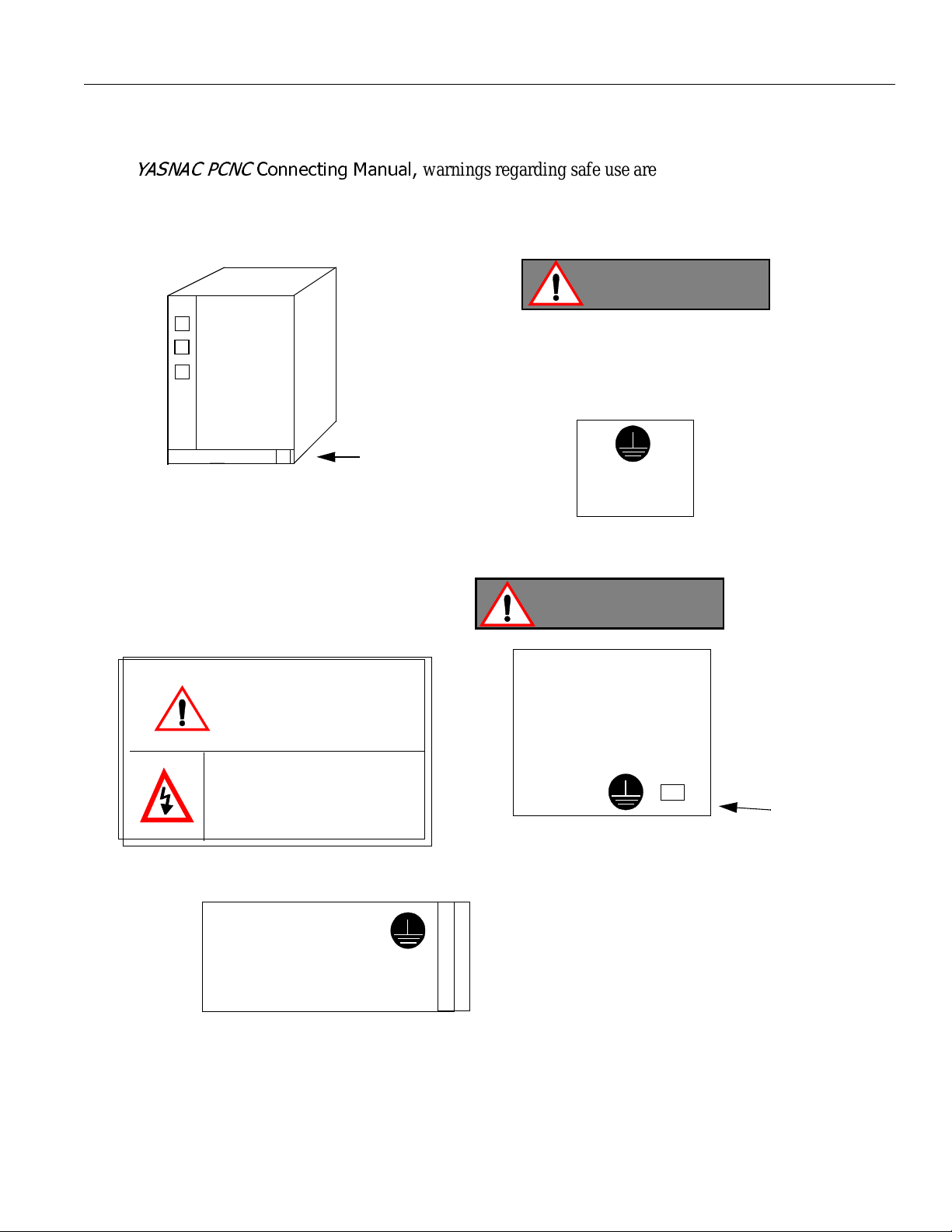
OPERATING SAFETY WARNINGS
In this
<$61$&3&1&
&RQQHFWLQJ0DQXDO
warnings regarding safe use are categorized as WARNING and
CAUTION (refer to Page 1 for an explanation of these terms) . An example of this warning method is as fol-
lows:
PCNC Unit
Read all Warning label’s
of PCNC Unit.
WARNING
CAUTION
WARNING LABEL
BE SURE TO CONNECT
GROUNDING LINE TO
GROUNDING TERMINAL
WARNING
PCNC Opeartion panel
with 14” CRT U ni t
14 “ CRT UNIT or
May cause electrical sho c k .
Do not touch inside.
( Make sure to connect grounding )
Read all the cautions and warnings
24 DC Power supply unit ( UPS 000004 )
xi
LCD ( Expected)
rear side warning
Label
(Make sure to connect grounding )
Page 13
YASNAC PCNC Connecting Manual Preface/Table of Contents
TRANSPORT PRECAUTONS
CAUTION
• When movin g the product, do not lift by the ca ble .
• Once the product has been installed on the machine and the eyebolts have been removed, insert
suitable size machine bolts in the mounting holes.
• The product should not be exposed to harmful environmental conditions, i.e., water, harmful
gases or liquids.
Failure to observe these precautions may result in personal injury or product damage.
STORAGE
CAUTION
• This product should not be exxposed to harmful environmental conditions, i.e, water, harmful
gases or liquids.
• Product should be stored in a clean indoor area that meets the following temperature and humidity
conditions:
• Ambient te mperature: -15
• Relative humidity : 10% to 90%
• Altitude : 1000 m or less ( 10000ft or less )
Failure to observe these precautions may result in personal injury or product damage.
o
C to 65oC (-5oF to 149oF)
xii
Page 14
YASNAC PCNC Connecting Manual Preface/Table of Contents
INSTALLATION
CAUTION
• Install peri pheral equipment in accordance with th e following:
1. A rust preventative substance has been applied to the motor shaft’s end an d flange. Remove
the substance using a cl ean cloth.
2. When connecting the motor shaft to a dr iven machine, be sur e to cente r-align accurately t o
prevent vibration.
3. Mount the servo unit(Converter,Inverter and A m plifier ) vertcally and faste n fir ml y in pla ce
with screws or bolts.
4. Since the servo unit (Converter,Inverter and Amplifier ) will generate heat, install the unit with
sufficient clearance for cooling air flow.
5. In order to reduce heat generation, position the servo unit’s(Converter,Inverter and Amplifier)
cooling fan outside of the enclosure for exposure to the exte rnal atmosphere for cool ing.
6. When circulating air inside of the enclosure, do not blow air directly onto the servo unit since
dust cont amination could occur.
7. Position and mount components so that they are easily accessible for inspection and maintenance.
Failure to observe these precautions may result in product failure.
CAUTION
• When installing this pro duc t, do not close the intake or exhaust port s, bu t take precautions to
prevent foreign matter fro m e nt eri ng this device
• Do not subject this pr oduct to any strong physical im pa cts.
• Set the power line capacity higher than this produ ct ’s power consumption level.
Failure to observe these precautions may result in personal injury or product damage.
xiii
Page 15
YASNAC PCNC Connecting Manual Preface/Table of Contents
WIRING
CAUTION
• Use the shortest wires when making connections.This helps prevent malfunction.
• Connect the +24V D C power supply to the PC NC unit .
1. The power supply shoul d be provided at the custome r’s site.
(The power supply unit , UPS000004, is available as an option.)
2. Supply the power in the range of +24V DC +
• Do not run the I/O signal wires with power wires or in the same duct. Ample separation of signal
wires from power wires will reduce the noi se i nfl uence.
• If noise occurs, use a noise suppressor to eliminate it. Refer to th e sec ti on in this connection
manual for noise filter specifications and capacities.Us e o f the correct n oise filter will reduce
noise influence.
• Be sure to complete the end-terminal-proc essing to the la st module of the remote I/O modul e .
Set the “TERMINATION” shorting pin to “ON”.
10% to the PC NC unit ’s inlet (CN 05).
Failure to follow these instructions could result in malfunction.
CAUTION
• Electrical wiring and connections should be performed by qualified personnel only.
Failure to observe this precaution could result in product failure, fire and/ or
personal injury or death due to electrical shock.
• Never connect a three-phase power supply to mot or output terminals, U,V or W of th e dri ve unit.
Damage to the device will occur if incorrectly connected.
• Select the type and size of wire based on your requirements and current capacity. When the
ambient temperature exceeds 30
conform to the local electrical codes and cable manufacturer’s specifications.
Failure to comply could result in an electrical fire.
o
C (86oF), the allowable current drops. Select the cable size to
• Use twis ted wire o r multi-core twisted p air shield ed wire for general signal wires and feedback
signal wires for the encode r.
These wire types help prevent malfunction.
xiv
Page 16

YASNAC PCNC Connecting Manual Preface/Table of Contents
CAUTION
• The current cap ac ity of 24V DC (external pow e r unit for input/output con ta ct s ) is de te rmined by
the number of contact points to be used. When the current ca pa city is low, install an additional
external power un it .
• A n enclosure for this product should be designed and const ruc t ed t o me e t th e fol lo w in g:
1. Use an airtight enclosure.
2. Limit the aver age temperat ure rise of air within the enclosure to less than 10
compared to the ambient te mperature.
3. Use a UL approved fan to circuate the air in a closed enclosure to improve cooling efficiency,
and to prevent abnorm al hea t ri se.
4. Seal the cable inlet, door, etc. completely.
5. Since a CRT display attracts airborne particles due to its high voltage that could result in
malfunction, therefore, provide an enclosure capable of preventing dust from entering the CPU.
6. Ambient magnetic field may cause CRT screen fluctuations, therefore, prevent this with a
layout and magentism shield.
7.In PC NC Unit,printe d c irc ui t bo ards,various units may ac cumlate dust from air,may result in
malfunctio n, therfore ,mak e s tructures to prevent the entry o f du s t.
8.Install packing on the cable inlet,doors,back covers,etc. to eliminate gaps or openings.
Failure to observe these precautions m ay result in product failure.
o
C (50oF)
xv
Page 17

YASNAC PCNC Connecting Manual Preface/Table of Contents
CAUTION
• Connect ea ch unit’s grounding line individually to the housing or grounding plat e.
See the followin g example:
V
,
S
200VA C
LF
.
.
U
M
V
External
Box
.
.
Operation relay
sequence
LF
W
N
C
N
C
AVR
E
E
B
,
F
Grounding at one
point (100Ω / less)
• Select the wire for grou n di n g in conf ormance with local electrical codes.
• Be sure to connect the motor’s grounding terminal to the drive unit’s grounding terminal.
• Ground at one point. (Ground resistance 100 Ω or less).
• Be sure to seperate the grounding line of the unit from the pow e r unit’s grounding line.
Failure to perform correct grounding can lead to malfunction.
xvi
Page 18

YASNAC PCNC Connecting Manual Preface/Table of Contents
APPLICATION SAFETY PRECAUTIONS
CAUTION
• When operating the unit, be sure to obs erve the fol lo w ing electrical safety procedure s
1.Do not touch the unit or terminal wire while the unit is ope rating.
2. Even though the unit has been turned OFF, it is still in charged status, so do not touch any
component parts for a minimum of five minutes.
Failure to observe this precaution could result in product failure, fire and/ or personal injury
or death due to electrical shock.
• Do not mishandle, pinch or ca use exc essive stress to cables.
Excessive load on the cable could cause electric shock.
• While the unit is turned O N, never touch any rotati ng pa rts.
Failure to observe this precaution could result in personal injury.
Never modify t he product
Free from explosiv e gases or steam
Free from oil,organic solv ent,corrosive liqui ds et c.
Vibration under (0.5 G).
Never disassmb le or modi fy the compon ents of the unit.
Never change the set values of the components and any variable resistors used in control panel.
Failure to observe this warning could result product failure, fire and/ or personal injury
or death due to electrical shock.
xvii
Page 19

YASNAC PCNC Connecting ManualChapter 1: General
Installation And Electrical Connection
This section addresses the basic system: configuration, specifications,
enclosure design, electrical connections and installation.
1
General
1.1 System Configuration. . . . . . . . . . . . . . . . . . . . . . . . . . . . . . . . . . . . . . . . . . . . . . .1 - 2
1.1.1 System Configuration. . . . . . . . . . . . . . . . . . . . . . . . . . . . . . . . . . . . . . . . .1 - 2
1.1.2 Connection between Devices . . . . . . . . . . . . . . . . . . . . . . . . . . . . . . . . . . .1 - 3
1.1.3 Connector Layout NC side . . . . . . . . . . . . . . . . . . . . . . . . . . . . . . . . . . . . .1 - 4
1.1.4 Connector Layout PC side . . . . . . . . . . . . . . . . . . . . . . . . . . . . . . . . . . . . .1 - 5
1.2 General Specifications . . . . . . . . . . . . . . . . . . . . . . . . . . . . . . . . . . . . . . . . . . . . . .1 - 6
1.3 Thermal Design of Enclosure. . . . . . . . . . . . . . . . . . . . . . . . . . . . . . . . . . . . . . . . .1 - 7
1.3.1 Thermal Design. . . . . . . . . . . . . . . . . . . . . . . . . . . . . . . . . . . . . . . . . . . . . .1 - 7
1.3.2 Dust Proof Design. . . . . . . . . . . . . . . . . . . . . . . . . . . . . . . . . . . . . . . . . . . .1 - 11
1.3.3 Countermeasure Against Magnetic Fields . . . . . . . . . . . . . . . . . . . . . . . . .1 - 12
1.4 Cable Clamp and Shielding . . . . . . . . . . . . . . . . . . . . . . . . . . . . . . . . . . . . . . . . . .1 - 13
1.5 Packaging . . . . . . . . . . . . . . . . . . . . . . . . . . . . . . . . . . . . . . . . . . . . . . . . . . . . . . . .1 - 14
1.5.1 General Notes . . . . . . . . . . . . . . . . . . . . . . . . . . . . . . . . . . . . . . . . . . . . . . .1 - 14
1.5.2 Installation of PCNC Unit. . . . . . . . . . . . . . . . . . . . . . . . . . . . . . . . . . . . . .1 - 15
1.5.3 Installation of Feed/Spindle Servopacks. . . . . . . . . . . . . . . . . . . . . . . . . . .1 - 16
1 - 1
Page 20
YASNAC PCNC Connecting ManualChapter 1: General
1.1 Syste m C onfi gur ati on
1.1.1 System Confi gur ati on
The PCNC unit of the YASNAC which i s hat che d i n the dia gram below is compo sed of two
boards: JCP20 and JFC20 (JZNC-JFC10). It is inserted to a PC extended bus (ISA) inside PC
case.
Its I/O module, servo uni t, spi ndl e dri ve and motor are the same as those of the YASNAC
J100 CNC UNIT.
FDD
PC NC case
PC
ISA bus
JFC10
DC
+24V
power
Mouse
Monitor with Touch screen
Keyboard
Feeding
servo unit
Spindle
drive unit
Machine
Feeding
motor
Spindle mo tor
I/O Module
High voltage
Device
machine side
Figure 1.1.1 YASNAC PCNC System Structure Diagram
1 - 2
on
Page 21
YASNAC PCNC Connecting ManualChapter 1: General
1.1.2 Connection Between Devices
CPU RACK UNIT
DATA
HDD
INP UT
PWR
VIDEO
CN01
CN02
CN03
CN04
CN05
CN11
CN12
CN13
CN14
CASE FAN
OUTOUT
PGS
(PO W E R
GOOD
SIGNAL)
NC POWER
SUPPLY
INPU T OUTPUT
AC230V
DC
OUT
NFB
ATX
MOTHER
BOARD
PS/2 MOUSE
PCI
ISA
FAN1
CPU
FAN
FAN3
IDE I/F
KBD
COM2
FDD
COM1
LPT1
VIDEO
CARD
JFC 20
JCP 20-1
PC PO W E R
SUPPLY
24VDC FOR
MACHINE I/O
CN1~6
I/O BOARD
FOR MACHINE SIGNAL
(FC8 X X )
CN11
CN13
SENSOR SIGNAL
CONVERTER UNIT
5CN
INPUT POWER UNIT
TB2
TB1
SVM
CRT
KEYBOARD
MOUSE
FDD
TS
CONTROL
SERVO ON
SHUT DOWN
MACHINE
CONTROL
SIGNALS
CN14
CN12
SERVO UNIT
SGDC-**AJA
4CN
1CN
Z AXIS
52CN
51CN
SGDC-**AJA
4CN
1CN
Y AXIS
52CN
51CN
SGDC-**AJA
4CN
1CN
X AXIS
52CN
51CN
C1MR-M5N
4CN
1CN
52CN
51CN
C1MR-MR5N
SVM
A1/A2
PWRDATA
TOUCH
SCREEN
MAC HINE O P . PAN EL I/O
CN5
I/O BOARD
FOR MACH INE
OP. PNL.
(JSP02/04)
CN3
3CN
2CN
3CN
2CN
3CN
2CN
2CN
REACTOR
R/S/T
A1/A2
X0100**
TB3
CN1
CN7,8,9
MACHINE PANEL
M
PG
M
PG
M
PG
UAASK*-**FZ*INVERTER UNIT
M
PG
SIGNALS
SGMG -
**A2AB *
FA
HPG
N
Figure 1.1.2.1 Detail Con nection of PCNC Unit wit h various devices.
1 - 3
Page 22
YASNAC PCNC Connecting ManualChapter 1: General
1.1.3 Connector Layout NC Side
The following figure gives the detail Conne ct ors Layout of YASN A C JZNC-JFC10 board.
Servo controller connector (CN01)
I/O module connecto r (CN02)
Power good signal connector (CN03)
Interruption setting short pi n (S11)
Memory address setting r otary swi t ch (S12)
I/O module po wer output ver ificati on L ED
I/O module power o utput connector (CN04)
Servo controller I/O connector (CN11)
Power On/Off connect or (CN12)
Fuse (HM03, 0.3A) (F1)
RS232C connector (CN14)
Direct IN/OUT connector (CN14)
System load switch (S1)
I/O module power input connector (CN 05)
I/O module power in put verif icat ion LED
Battery power reply supply connector (CN06)
Battery
FIGURE 1.1.3.1: Details Layout of YASNAC JZNC-JFC10 Board
System load switch (S1)
(from top: 1, 2, 3, 4)
Battery alarm LED
System load rotary switch (S1)
1 - 4
Page 23
YASNAC PCNC Connecting ManualChapter 1: General
1.1.4 Connector Layout PC Side
FIGURE 1.1.4.1: Connector Layout on the top view of the PCNC CPU rack
1 - 5
Page 24

YASNAC PCNC Connecting ManualChapter 1: General
1.2 G ene ral Specifications
The enclosure shoul d be designed to meet all of th e following conditi ons.
Table 1.2.1: Specifica t i o ns
Item Specifications
Ambient Conditions
Storage and
Transportation
Temperature*
Humidity 20% to 80% RH (with operation)
Vibration
during operation
PCNC Unit input power supply
Power Supply Unit UPS000004
Operating
(around
enclosure)
Others Free from dust, coolant or organic solvent
PCNC unit
I/O module
Servopack
14” Color mon itor with
touch screen
10% to 90% RH (with non-operation)
• Input power supply voltage: 180V-264VAC
• Frequency: 47 Hz to 63 Hz
• Momentary interruption: 0.5 cycle (0 VDC)
o
C to +65oC
-15
Less than 4.9m/s
+24VDC+
180V-264V AC
10%
o
0
Note: Avoid installing th e control panel in a loca t ion subject to direct sunlight, ne ar heat
generating devices or outdoors even if the ambient temperature is within the specified
range.
C to +53oC
1 - 6
Page 25
YASNAC PCNC Connecting ManualChapter 1: General
1.3 The rm al Design of Enclosure
1.3.1 Thermal Design
Design of the encl osure shoul d be made on the basis that the ave rage temperature increase of
air within the encl osure (containing t he PC NC unit and other components) should be 10
below the external air temperature.
(1) Temperatu re In cre ase within th e Enclosure (Average Temperature Increase )
The internal temperature increase (sheet metal enclosure) is generally as follows:
P
∆Τ=
P
=
qe
.
k A
where,
o
C
∆Τ : Interna l temperature incr e ase (
o
C)
P : Heat generation in enclosure (W)
qe : Enclosure heat percolation ratio (W/
k : Heat transit ratio of sheetmetal (W/m
6W/m
A : Efficient heat diffusion area of enclosure (m
2o
C: With interna l c o oling fan
4W/m
2o
C: Without internal cooling fan
o
C)
2o
C)
2
)
1200
All dimensions in millime te rs
800
Fig 1.5 Dim ensions of Enclosu re
700
Efficient heat diffusion a rea is in dependently loca ted, so bottom area is excluded.
A=4.16m
2.
If the heat gener at ion in the enclosure i s supposed to be 246W (113 W in CNC
portion, 104 W in servo portion, and 29 W in I/o portion),
P
∆Τ=
=
P
=
qe
246
6 x 4.16
.
k A
= 9.9 (oC)
1 - 7
Page 26
YASNAC PCNC Connecting ManualChapter 1: General
(2) Heat Exchanger Cooling Capacity
Where coolin g capacity is insufficie nt eve n wit h a c irc ulating fan mount ed in the
enclosur e, Yaskawa can provide heat exchangers.
Table 1.3. 1.1: Heat Exchang e rs
Heat Exchanger Cooling Capacity External Dimensions (mm)
o
REX1550 100W /10
HEATEX02 250W /10
C 295 width x 890 height x 50 depth
o
C 440 width x 924 height x 50 depth
The heat generation indicat ed in the above tabl e is the allowabl e heat generated wh en the
internal tempe ra ture increase in the enclosure is limited t o unde r 10
o
C.
Example: Allowable Heat Generated in the Enclosure with Heat Exchanger
The amount of internal heat generated to make th e internal temperature under 10
o
the enclosur e is e quipped with a HEATEX02 Heat E xchanger is expre ssed by the
following equation:
.....................................................
P= k.A.∆Τ+ 250 W/10oC
= 6 x 4.16 x 10 + 250
o
= 499 W/10
C
therefore, it is ne ce ssary to be under 499W.
(3) Mounting Heat Exchanger
Heat exchange r should be mounted on the enclosure pro vided by the machine tool
builder. Fig. 1.5 shows a mounting examp le . Mo unt the exc ha nger so that the internal air
is drawn from the upper portion and discha rged th rough the lower port ion, while external
air is drawn in from th e lo w er portion and discharged thro ugh the upper portion.
C when
Internal air
Enclosure
External air
Heat exchanger
Fig 1.3.1.1: Mounting of Heat Exchanger on the enclosure made by Machine builder
1 - 8
Page 27

YASNAC PCNC Connecting ManualChapter 1: General
(4)Heat Gene rat ion by Respective Units
Unit Type Total Heat
PCNC rack JZNC-JPCRKM_-_
14” Color CRT with
Touchscreen
I/O Module
Converter
JZNC-JPCOP-_ _ _
JANCD-FC810* 29 29 0 JANCD-FC860* 29 29 0
JANCD-FC861* 14.5 14.5 0 CIMR-MR5N23P7 84 44 CIMR-MR5N25P5 84 44 CIMR-MR5N27P5 119 61 CIMR-MR5N2011 152 70 CIMR-MR5N2015 204 88 CIMR-MR5N2018 273 108 CIMR-MR5N2022 335 132
Generation
(W)
Internal
Heat
Generation
(W)
Minimum
Wind
Velocity for
Cooling
2.5
Spindle Inverter
Reactor
CIMR-MR5N2030 392 160 CIMR-MR5N23P7 84 44 CIMR-MR5N25P5 185 58 CIMR-MR5N27P5 244 77 CIMR-MR5N2011 307 89
2.5
CIMR-MR5N2015 454 119 CIMR-MR5N2018 565 144 CIMR-MR5N2022 717 180 CIMR-MR5N2030 869 219
UZBA-B 20A 0.53 mH 35 35 0 UZBA-B 30A 0.35 mH 45 45 0
UZBA-B 40A 0.2 65 mH 50 50 0
UZBA-B 60A 0.18 mH 65 65 0 UZBA-B 80A 0.13 mH 75 75 0
UZBA-B 90A 0.12 mH 90 90 0 UZBA-B 120A 0.09 mH 90 90 0 UZBA-B 160A 0.07 mH 100 100 0
1 - 9
Page 28
YASNAC PCNC Connecting ManualChapter 1: General
Unit Type Total Heat
SGDC-05AJ A 28 10 SGDC-10AJ A 48 12
Servo Unit
SGDC-15AJ A 73 15 SGDC-20AJ A 108 18 SGDC-30AJ A 148 22 SGDC-50AJ A 208 28
1. The heat generated by the CNC unit varies depending on the addition
POINT
of options. The heat generated by the I/O module varies with I/O
status.
2. Internal heat generation is the heat remaining inside of the enclosure
when the servo uni t’s fin is exposed outside of the enclosure, and
when the external air is applied to the fin at greater than 2.5m/s
Generation
(W)
Internal
Heat
Generation
(W)
Minimum
Wind
Velocity for
Cooling
2.5
3. Thermal design of th e e nclosure to house the servo unit varies with
machine specifications, but is acknowledged to use a value of 70% of
the load fa ctor.
1 - 10
Page 29
YASNAC PCNC Connecting ManualChapter 1: General
1.3.2 Dust proof Design
Dust proof Design and Construction
PCNC units and other components (especially CRTs) housed in a machine tool enclosure are
exposed to an environment with airbo rne matter, e.g., dust. oil, coolant mi st, etc.Since these
elements could cause control component malfunction, enclosures should be designed and built
to prevent such m atter from entering as follo w s:
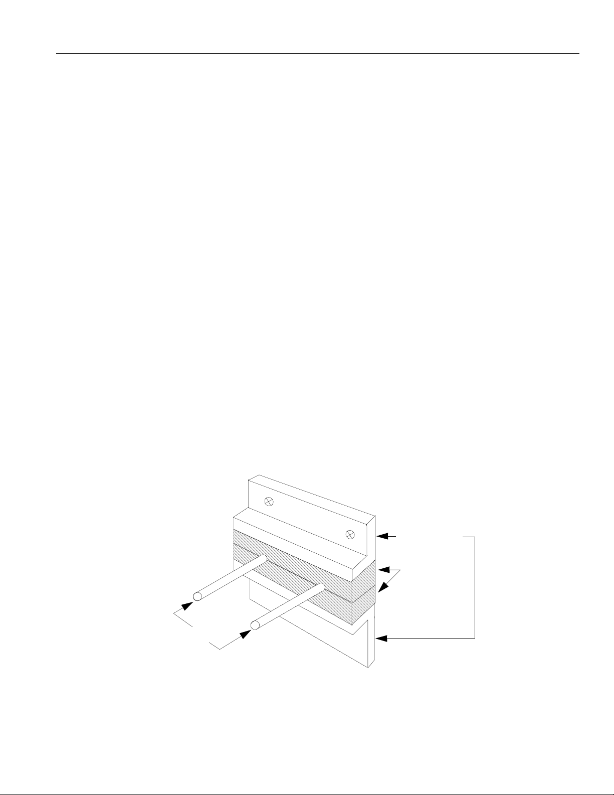
• Use an air-tight enclosure.
• Seal the cabine t inlet with packin g mat erial. Refer to Fig. 1.3.2.1.
• Secure the rear do or li d w ith packing material . Refe r to Fig, 1.3.2.2.
• The enclosure’s front surfa ce s w ith PCN C operating panels and are dust proof, but do not
install them where liquid coolants are present. The periphery should be sealed with suitable
materials.
The CRT unit’s high voltage will attract airbo r ne dust, so w hen mounting the CRT unit’s
pendant box please take note of the following:
1. Seal the cab le inl et , do or, rear lid op ening clearance s w it h packing materi al .
2. The CRT Unit’s mounting surface has been factory sealed.
3. Seal any other op enings.
4. Since oil wil l enter the encl osure through screw holes an d collect on the
internal ceiling surface, apply suitable packing material to seal these holes.
Metal fitting
Packing
Cable
Fig. 1.3.2.1 Cable Inlet
1 - 11
Page 30
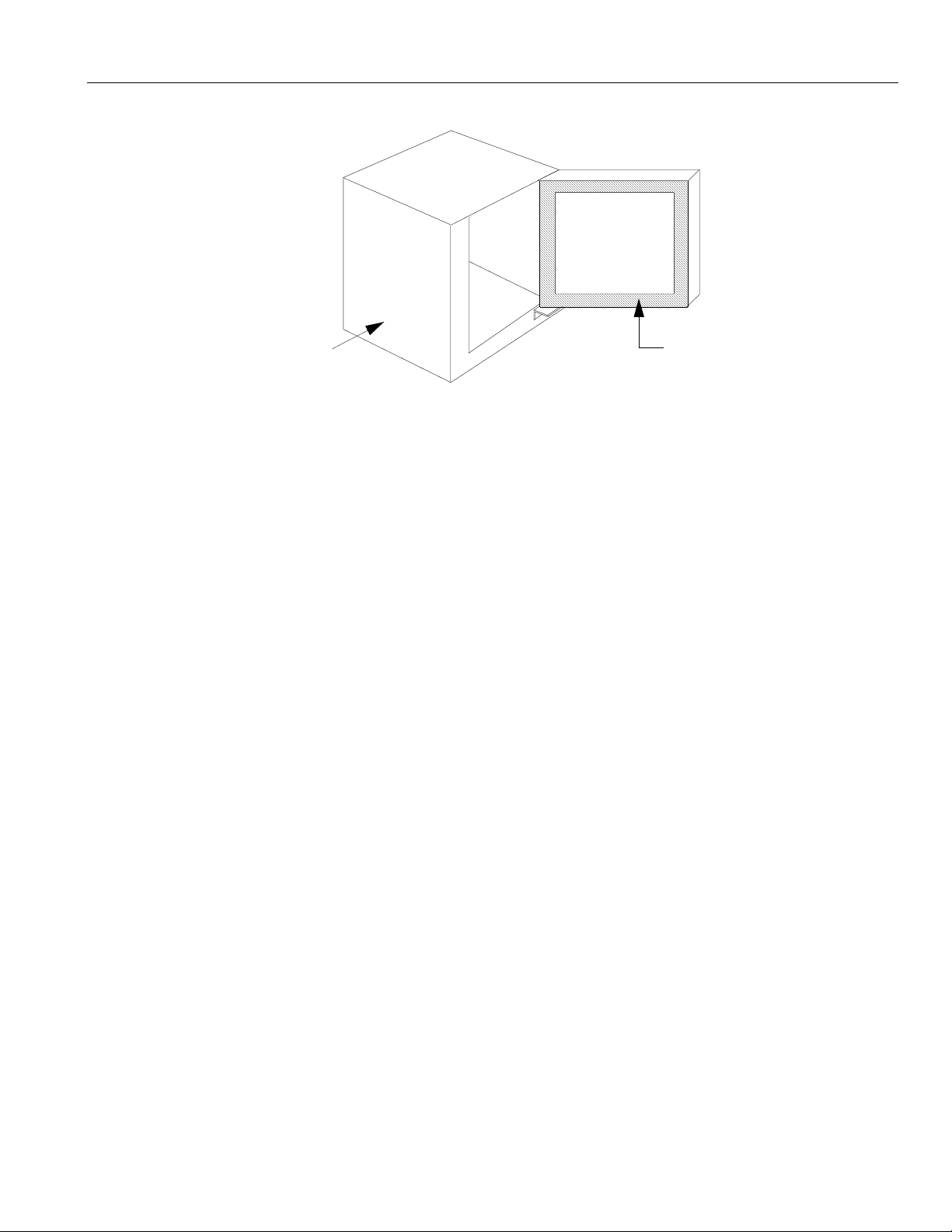
YASNAC PCNC Connecting ManualChapter 1: General
Pendant box
Fig. 1.3.2.2 Door Packing
1.3.3 Counterme asures against Magne ti c Fields
The CRT screen’s d isp lay may fluctua te due to ambien t magnetic fiel d s. To prevent this, keep
magnetic generating materials, e.g., transformers, reactors, fans, electro-magnetic switches,
solenoid relays, exchange power cables, etc. a minimum of 300mm from the CRT.
The value of 300mm is a general standard and coul d va ry depending on the situation,
therefore, be aw a re of the presence of magnetic generating sou rces when positioning the
Packing
CRT unit.
1 - 12
Page 31

YASNAC PCNC Connecting ManualChapter 1: General
1.4 Cable Clamp and Shielding
If the cables wired to the PCN C un it nee d to be shiel de d, the y mu st be grounded using the
grounding plate wit h cable clamp hardware. Because this cl amp serves both as cable support
and shielding, they must be installed carefully so that safe system motion can be assured.
1. Peel the cable coating to expose the cable where it connects the grounding plate with the
cable clam p.
2. The cable clamps (with the cables) must be installed to the grounding plate as shown in the
following diagram :
VGA
POWER
DATA
POWER
DATA
CRT
Touch
Panel
FDD
Keyboard
Mouse
2m max.
VGA
EX.DC
PARALLEL CD-ROM ZIP
24VDC
COM1
YENET IO
FDD
PS/2
SERIAL
CARD
(OPTION)
CPU
RACK
IPU
Drive IO
YENET D
IPU
Drive IO
YENET
YENET
24VDC
Drive
Pack
IO
Ferrite Core
Shield Clamp
YENET
24VDC
Last IO
FIGURE 1.4.1: Yasnac PCNC Shielding and Ferrite core clamping points
1 - 13
Page 32

YASNAC PCNC Connecting ManualChapter 1: General
1.5 Packaging
When designing the enc l osure to house the CNC unit and ot he r equipment, the con struction
should provide for th e fol l ow ing:
1.5.1 Genera l Notes:
• The enclos ure must be ai r-t ight.
• Internal layout of c omponents should pr ovi de for ease of mounting, inspection maintenance,
and removal.
• There should be a physical gap of 100mm be tween component s and the enclosure’s wall so
not to restrict air flow for coolin g.
• If the operation panel is built into the machine’s enclosure door, provisions to prevent vibra-
tion from the machine is necessary.
• The average temperature increase in the enclosure should be limited to 10
o
C compared to the
external ai r.
• Use a fan to cir cula te ai r to impr ove co oli ng e f fi cien cy w ith in t he encl os ure . As a g ener al r ule,
the fan should blow a ir upward at 1m/s over the p. c. boa rd ’s surface.
• The fan should not bl ow ai r directly onto the p.c . board.
• To prevent malfunctions due to noises, kee p noi se generating eleme nt s 10m aw ay from AC
power supply cables an d com ponents (over 90VDC).
• When wiring, separate AC from DC lines, and separate primary side from the transfor mers’s
secondary side, line filter, etc.
1 - 14
Page 33

YASNAC PCNC Connecting ManualChapter 1: General
1.5.2 Installing the PCNC Unit
• The PCNC unit has a bui lt -i n fan that blows air (1 m/s) over the upper side of the PCNC unit.
• Provide clear ances of 50 mm min imum above the 100 mm minimum bel ow the PCNC unit for
ventilation and maintenanc e.
JZNC - JFC10
)
P
)
S
/
O
/
I
V
S
V
(
R
1
D
0
(
N
1
C
1
N
C
)
O
I
R
(
2
0
)
N
U
C
P
I
(
2
)
1
S
N
C
G
P
(
3
0
N
C
1
F
)
C
L
P
M
O
C
(
3
1
N
C
V
5
+
)
)
V
N
4
I
2
D
+
(
/
4
0
V
4
5
1
N
+
N
C
C
T
U
O
(
1
W
S
)
V
4
5
2
0
+
N
C
N
I
(
V
4
2
+
)
T
A
B
(
6
0
1
N
C
2
3
4
T
A
B
3
W
S
DETAIL 1
]
0
4
.
0
[
6
1
.
0
1
R2.54 [0.10]
R6.35 [0.25]
Y
R
E
T
T
A
B
FIGURE 1.5.2. 1: Mounting of PCNC Unit
1 - 15
Page 34

YASNAC PCNC Connecting ManualChapter 1: General
1.5.3 Installing the Feed/Spindle Servopacks (Amplifiers)
• The Servopack is t o be w all-mounted vert ically using screws or bolts.
• Locate the Servopack so that inspection, maintena nc e and part replacem e nt can be easily
made.
• The Servopack w i ll generate some heat, so mou nt wi th sufficient space around the unit .
• To reduce heat gene rat ion, mount the cooling fin external to the Serv opa ck’s enclosure with
the fan blowing air on the cooling fin @ 2.5m/s.
• Internal air should not be blown directly ont o th e Servopack since this could cause dust contamination.
Cooling fin
External Air
Fig. 1.5.3.1 Cooling Fin Installed Outside of Enclosure
Feed Servopack
Converter & Inverter
1 - 16
Page 35

YASNAC PCNC Connecting Manual Chapter 2: Power Supply
2
Power Supply Connection
Connecting Power Supply To Compo nent s.This section addresses the following electrical
connections: power supply to components, detailed connections and LED connections.
2.1 Connection between Devices . . . . . . . . . . . . . . . . . . . . . . . . . . . . . . . . . . . . . . . . .2 - 2
2.1.1 Power Supply specifications for PCNC and I/O units . . . . . . . . . . . . . . . .2 - 2
2.1.2 Power Supply connections to PCNC . . . . . . . . . . . . . . . . . . . . . . . . . . . . .2 - 3
2.1.3 Power Supply Connections to PCNC and I/O units . . . . . . . . . . . . . . . . . .2 - 3
2.1.4 Power Supply to Converter unit . . . . . . . . . . . . . . . . . . . . . . . . . . . . . . . . .2 - 4
2.2 Detailed Connections . . . . . . . . . . . . . . . . . . . . . . . . . . . . . . . . . . . . . . . . . . . . . . .2 - 5
2.2.1 Power Supply to PCNC unit. . . . . . . . . . . . . . . . . . . . . . . . . . . . . . . . . . . .2 - 5
2.2.2 Power Supply to Converter. . . . . . . . . . . . . . . . . . . . . . . . . . . . . . . . . . . . .2 - 7
2.2.3 Example of Circuit Diagram . . . . . . . . . . . . . . . . . . . . . . . . . . . . . . . . . . .2 - 8
2.3 LED for Power Input /Output. . . . . . . . . . . . . . . . . . . . . . . . . . . . . . . . . . . . . . . . .2 - 9
2.3.1 LED for PCNC Power Input. . . . . . . . . . . . . . . . . . . . . . . . . . . . . . . . . . . .2 - 10
2 - 1
Page 36

YASNAC PCNC Connecting Manual Chapter 2: Power Supply
2.1 Connection between Devices
This section descri bes connections betw ee n devices, connector nu m be rs and connector type. For
power supply connection use a commercially available standard power supply or Power Supply
Model UPS000004.
2.1.1 Power Supply specifications for PCNC Unit and I/O units.
Power supply connec ti on to the PCNC unit differs depend ing on whether using a
commercially a vai l abl e standard power supply for both PCNC and I/O units or use a
recommended po w er suppl y uni t on ly fo r PCN C a nd use ano th er power supply for I/O units.
(1) Selection of Power Supply
(a) U sin g a Standard Power Supply
Excluding +24 V pow e r supply for I/O input and out put,90W is required for the total
PCNC system. Select a suitable power supply with consideration for temperature
derating charac te ri sti cs.
• Power supply for I/O input and output
Select a suitable power supply by referring to the calculation example shown in
Section 10.3.3 “Power Supply for I/O Signal”.
•Power supply for PCNC Unit
In order to provid e 90W power capacit y or greater when th e in te rnal panel
temperature is 55oC, a +24V output power supply with ca pa city of 150W and
greater is required: (Recommended UPS000004 is rated for 150 Watts.)
Select a power supply with the following specifi ca tions:
Power capacity of 150W or greater.
Power supply with the derating characteristics of 60% or greater when the internal
panel temperat ure is 55
o
C. (150W x .06 = 90W)
•Recommended Power Supply:
UPS000004
Operating Condi tions:
o
At 50
At 55
C - 100% ( Out put rated Curre nt 6.5 Amps)
o
C - 80 % ( Derated Output Current )
For more details conta ct the pow e r su ppl y manufacturer.
2 - 2
Page 37

YASNAC PCNC Connecting Manual Chapter 2: Power Supply
2.1.2 Power Supply Connections to PCNC
CNC unit Power supply unit(UPS00004)
JANCD-JFC10 CN05(1-178293-2)
+24VDC
1+24V
Stabilized power supply
20
3 FANALM
V
24
*Note : Derating for ambient te m pe r at ure should be considered.
FIGURE 2.1.2.1 Power Supply to PCNC Unit when using recommended Power Supply Unit.
2.1.3 Power Supply Connections to PCNC and I/O Units
UWR00306
PCNC UNIT
JANCD-JIF10
CN05 CN04
+24VDC
5V DC & GND
*
Terminal
Block
5V
UWR00307
+24VDC+
3.0 A min. (Note*)
24V
10%
CN 13
JANCD-FC8_ _
CN 14
UWR00305
CN 13
JANCD-FC8_ _
AC Power Supply
180V-264V AC
Single phase
CN 14
24V DC
+24V supply
(UPS00004)
GND
CN 05
JSP04/JSP02
Machin e Tool
Builder supply
CN 06
+24V according
to I/O
requirements.
* To be provided by Mach ine Tool builder
FIGURE 2.1.3.1 Power Supply to PCNC unit when using re c omm e nded Power Supply Unit
2 - 3
Page 38

YASNAC PCNC Connecting Manual Chapter 2: Power Supply
2.1.4 Power Supply to Converter Unit
Converter unit
MC
CIMR-MR5
L
FIGURE 2.1.4.2 Connection between Devices
Table 2.1.4.2 Component Selection for Power Supply Circuit
Converter
Type CIMR-
MR5N2
ooo
3P7 3.7 4.6 7 30A 20A
Applicable
Capacity
(kW)
Output
Capacity
(kW)
Power
Source
Capacity
(KVA)
Breaker
1MCCB
TXR
MCCB
Electro-
magnetic
Contactor
1MC
Power supply
Reator*
1L
20 A 0.53 mH
(x 002491)
(x 010057)
5P5 5.5 6.8 9 40A 30A
7P5 7.5 9.3 12 50A 40A
011 11 13.6 19 75A 60A
015 15 18.6 24 100A 75A
018 18.5 22.9 30 125A 100A
022 22 27.2 36 150A 125A
030 30 37.1 48 175A 150A
30 A 0.35 mH
(x 002492)
(x 010058)
40 A 0.265 mH
(x 002493)
(x 010059)
60 A 0.18 mH
(x 002495)
(x 010060)
80 A 0.13 mH
(x 002497)
(x 010061)
90 A 0.12 mH
(x 002498)
(x 010062)
120 A 0.09 mH
(x 002555)
(x 010063)
160 A 0.07 mH
(x 002556)
(x 010064)
*Note: Code in upper row: with leads
Code in lower row : with terminals
2 - 4
Page 39

YASNAC PCNC Connecting Manual Chapter 2: Power Supply
2.2 Detailed Connection
This section desc rib es th e de ta iled connection of power supply.
2.2.1 Power Supply to PCNC unit
CNC unit Power Supply Unit (UPS000004)
JANCD-JFC10 CN05(1-178293-2)
1+24V 20 3 FANALM
V
24
+24VDC Stabilized
power supply
+24VDC+
3.0 A min. (Note*)
10%
ó
AC Power Supply
180V-264V AC
Single phase
*Note: Derating for ambient temperature should be considered.
JANCD-JFC10 CN05
Connector specifications
Connector : 1-178288-3
(3PIN)
Manufacturer : AMP
UPS000004
Connector specification
Criimp terminal : 1.25 -4
Recommended cable : VCT type, 2mm2 x 5 cores (DE8402398)
L
N
FG
+24V
0
V
24
1
Select proper
cable fit for the
power supply
2
terminal.
200 VAC Single-phase
FIGURE 2.2.1.1 Power supply connections to PCNC Unit and 24V DC Power supply unit.
2 - 5
Page 40

YASNAC PCNC Connecting Manual Chapter 2: Power Supply
ó
UPS000004
24 DC Power
Supply
L
N
LF
180V~264V
1Ph AC
PCNC CPU
L
N
FIGURE 2.2.1.2 Power supply connections to PCNC Unit and 24V DC Power supply
PCNC Power Socket and Frame ground details
JZNC - JFC10
)
P
)
S
/
O
/
V
I
S
(
V
R
1
D
0
(
N
1
C
1
N
C
)
O
I
R
(
2
0
)
N
U
C
P
I
(
2
)
1
S
N
C
G
P
(
3
0
N
C
1
F
)
C
L
P
M
O
C
(
3
1
N
C
V
5
+
)
)
V
N
4
I
2
D
+
(
/
4
0
4
V
1
5
N
+
N
C
C
T
U
O
(
1
W
S
)
V
4
5
2
0
+
N
C
N
I
(
V
4
2
+
)
T
A
B
(
6
0
1
N
C
2
3
4
T
A
B
3
W
S
FG
LF - Line F ilter. Use line filter. For select ion of Line f ilter
refer Appendix-1.
Note: Use 3.5mm sq or more for the Frame ground wire
DETAIL 1
]
0
4
.
0
[
6
1
.
0
1
R2.54 [0.10]
R6.35 [0.25]
Y
R
E
T
T
A
B
FIGURE 2.2.1.3 PCNC unit frame ground wire to be connected
2 - 6
Page 41

YASNAC PCNC Connecting Manual Chapter 2: Power Supply
Note: Please follow the Frame Ground connection details for the machine and electrical
cabinet.
1. Connect FG Cable from custom e rs ma in grounding point to Machine’s electrical
cabinet where PCN C i s mounted.
2. Connect FG cable from customers ma i ns
FIGURE 2.2.1.4 YASNAC PCNC CRT Power and Ground Wiring
Note: 1. Connect CRT ground wire only to the CRT chassis ground terminal. Do NOT
connect ground wire to terminal “E” on the main p ower terminal block of the CRT
unit.
2. CRT G round wire must be a separate wire directly co nnected to the main cabinet
ground plate or grou nd ba r. Any other connections to the machine operation box
should be done using sep ar at e gro und wires.
2 - 7
Page 42

YASNAC PCNC Connecting Manual Chapter 2: Power Supply
2.2.2 Power Supply to Converter Unit
Converter unit
TXR MCCB
CIMR-MR5
R/L1
1L
1L
S/L2
MC
.
MC TXR MCCB
R
200/220 / 230 VAC-15% to 10%
50/60 Hz +
S
2Hz
1L
T/L3
A1
A2
FIGURE 2.2.2.1 Detailed Connection of Power
MC TXR MCCB
.
Fig. 2.2.2.1 Detailed Connection of Power
r
t
T
2 - 8
Page 43

YASNAC PCNC Connecting Manual Chapter 2: Power Supply
2.2.3 Circuit Diagram Example (Power magnets & PCNC CN12 Control Signals)
To Customer PWR supply
To fan for air circulation
inside panel
CN12 (IPU)
FIGURE 2.2.3. 2 Circuit Diagram Example
2 - 9
Page 44

YASNAC PCNC Connecting Manual Chapter 2: Power Supply
2.3 LED for Power Input/Output
I/O module power output verification LED
I/O module power input verification LED
FIGURE 2.3.0.1 LED for PCNC Input/Output Power Indication on JCNC-JFC10 Board
2 - 10
Page 45

YASNAC PCNC Connecting Manual Chapter 2: Power Supply
2.3.0 LED for PCNC Power input
The status of +24V pow er supply to the CNC uni t ca n be confirmed by the LED.
The LED is lit when +24V power is supplied properly.
When +24V powe r is not supplied or when the fuse in side the PCNC unit is blown ou t du e to a
fault of PCNC unit, the LED will be unlit.
2 - 11
Page 46

YASNAC PCN C Connecting Manual Chapter 3: Connect i on of PCNC Operation Pan el
3
Connection of PCNC Operation Panel
CONNECTING PCNC OPERATOR PANEL AND PCNC
This section addresses the electrical connection between the PCNC unit
and the CNC Operator panel.
3.1 Connection between Devices . . . . . . . . . . . . . . . . . . . . . . . . . . . . . . . . . . . . . . . . . . 3 - 2
3.1.1 Connection with the Operation panel . . . . . . . . . . . . . . . . . . . . . . . . . . . . . . 3 - 2
3.2 Detailed Connection of PCNC Operation panel. . . . . . . . . . . . . . . . . . . . . . . . . . . . 3 - 3
3.2.1 Connection with Operation panel. . . . . . . . . . . . . . . . . . . . . . . . . . . . . . . . . 3 - 3
3.3 General notes on Connection with operation Panel . . . . . . . . . . . . . . . . . . . . . . . . . 3 - 8
3.3.1 JANCD-JSPO4/JANCD-J861 . . . . . . . . . . . . . . . . . . . . . . . . . . . . . . . . . . . 3 - 8
3.3.2 PCNC Connections Layout. . . . . . . . . . . . . . . . . . . . . . . . . . . . . . . . . . . . . . 3 - 9
3.3.3 Extended I/O board FC861 and Remote Machine Pen da n t connections . . . 3 - 10
3 - 1
Page 47

YASNAC PCN C Connecting Manual Chapter 3: Connect i on of PCNC Operation Pan el
3.1 C onne cti on Be tw e en Devices
3.1.1 Connecti on with Operation Panel
CPU RACK UNIT
ATX
MOTHER
BOARD
IDE I/ F
KBD
COM2
FDD
COM1
PS/2 MOUSE
LPT1
PCI
ISA
VIDEO
CARD
JFC20
HDD
DATA
PWR
VIDEO
CN01
CN02
CN03
CN04
CN05
DC
OUT
(a)
(b)
(c)
(d)
(e)
(h)
(f)
(g)
CRT
KEYBOARD
FDD
CONTROL
SERVO ON
SHUT DOWN
MOUSE
PWRDATA
TS
TB3
TOUCH
SCREEN
FAN1
CPU
FAN
JCP20-1
FAN3 CASE FAN
PC POWER
SUPPLY
INP U T
CN11
CN12
CN13
CN14
OUTOUT
(PO W E R
SIGNAL)
NC POWER
SUPPLY
INP U T OUTPUT
AC230V
PGS
GOOD
NFB
INPUT POWER UNIT
TB2
TB1
SVM
3 - 2
Page 48

YASNAC PCN C Connecting Manual Chapter 3: Connect i on of PCNC Operation Pan el
3.2Detailed Connection of PCNC Operation Panel
3.2.1 Connection with Operation P anel
(a) Connection det ai ls be twe en PCN C CPU unit and CRT display unit
ATX MOTHERBOARD
PCI1
PCI BUS
DISPLAY CARD (PT75)
J1
RED -1 -1 R E D
GREEN -2 -2 G R E E N
BLUE -3 -3 B L U E
GND -4 -4 G N D
GND -5 -5 G N D
RED GND -6 -6 R E D G N D
GREEN GND -7 -7 G R E E N G N D
BLUE GND -8 -8 B L U E G N D
N/A -9 -9 N /A
GND -10 -10 G ND
GND -11 -11 G ND
N/A -12 -12 N/A
HSYNC -13 -13 HSYN C
VSYNC -14 -14 VSYNC
N/A -15 -15 N/A
SHELL
FROM C RT PO W ER
(2-10 E)
N.C.
14 INCH CRT
VIDEO
SHELL
POWER
L
N
E
(b) Connection detail between PCN C CPU Unit and Key board
ATX MOTH ERBO ARD
KB
KBD DATA -1 -1 KB D D A T A
GND -3 -3 G N D
KBD PW R -4 -4 K B D PW R
KBD CLK -5 -5 K B D C L K
-2
-6
SHELL
3 - 3
KEYBOARD
Page 49

YASNAC PCN C Connecting Manual Chapter 3: Connect i on of PCNC Operation Pan el
(c) Connection detail between PC N C CPU U ni t and Se rial Mo use
ATX MOT HE RB O ARD
COM2
DCD -1
RX -2
TX -3
DTR -4
GND -5
DSR -6
RTS -7
CTS -8
RI -9
SHELL
FERRITE
CORE
FERRITE
CORE
PS/2 T O S E RIAL
ADAPTER
RZD
-1 DCD
-2 RX D
-3 TXD
-4 DTR
-5 GND
-6 DS R
-7 RTS
-8 CTS
-9 RI
SHELL
GND -3
DATA -1
+5V -4
CLK -5
SERIAL
MOUSE
-2
-6
3 - 4
Page 50

YASNAC PCN C Connecting Manual Chapter 3: Connect i on of PCNC Operation Pan el
(d) Connection details betwe en PCNC CPU unit and FDD
ATX MOTHER BOAR D
GND -1, 3 ,5,7,9,11,13
-15,17,19,21,23
-25,27,29,31,33
NORMAL/-HD -2 -2 NORMAL/-HD
IN USE/-SIDE LD . -4 -4 IN USE/-SIDE L D.
-DRIVE SELECT 3 -6
-DRIVE SELECT 0 -10
-DRIVE SELECT 1 -12
-DRIVE SELECT 2 -14
-MOTOR ON -16
-DIR ECT ION -1 8
WR ITE DATA -2 2
-WRITE ENABLE -24
-TRACK00 -2 6
-WRITE PROTECT -28
READ DATA -30
-SIDE SELECT -32
DISK CHG./-READY -34
FDC FDD DATA
-INDE X -8
-STEP -20
FDD PORT
FDD PORT
-1,2, 3 ,4,5,6,7 G ND
-8,9,10,11,12
-13,14,15,16,17
-20 NORMAL/-HD
-21 IN US E/-SIDE L D.
-22 -DRIVE SELECT 3
-23 -IN DEX
-24 -DRIVE SELECT 0
-25 -DRIVE SELECT 1
-26 -DRIVE SELECT 2
-27 -MOTO R ON
-28 DIR SELECT
-29 -S T EP
-30 WRITE DATA
-31 -WRITE ENA BLE
-32 -T R ACK00
-33 -WRITE PROTEC T
-34 READ DATA
-35 -SIDE SELECT
-36 DISK CHG./-READY
-18
-19
-37
SHELL
FERRITE
CORE
FERRITE
CORE
FLOPPY DISK DR IVE UNIT
3.5" 1.44MB
-1,3, 5,7 ,9 ,1 1, 13 G ND
-15,17,19,21,23
-25,27,29,31,33
-6 -DRIVE SELE CT 3
-8 -INDEX
-10 -DRIVE SELECT 0
-12 -DRIVE SELECT 1
-14 -DRIVE SELECT 2
-16 -MOTO R ON
-18 DIR SELECT
-20 -S T EP
-22 WR ITE D AT A
-24 -WRITE ENA BLE
-26 -T R ACK00
-28 -WRITE PROTEC T
-30 READ DATA
-32 -SIDE SELECT
-34 DISK CHG./-READY
FROM A UX
DC OUTPUT
(3-8B)
-4 +12V
-3 G N D
-2 G N D
-1 +5V
FERRITE
CORE
TB3
+12V
GND
GND
+5V
FDD POWER
-1
-2
-3 GND
-4 +5V
CONTROLLER
POWER
TO T/S
(7-13E)
3 - 5
Page 51

YASNAC PCN C Connecting Manual Chapter 3: Connect i on of PCNC Operation Pan el
(e) Connection details Betw e en PCNC CPU unit and Touch screen
ATX MO THERBO ARD
COM1 P2
DCD -1
RX -2
TX -3
DTR -4
GND -5
DSR -6
RTS -7
CTS -8
RI -9
SHELL
FERRITE
CORE
CONTROLLER
FROM T/S
POW ER
(6-14B )
FERRITE
CORE
-1 D C D
-2 R X
-3 T X
-4 D T R
-5 G N D
-6 D S R
-7 R T S
-8 C T S
-9 R I
SHELL
-1 + 5V
-2 G N D
-3
-4
TOUCHSCREEN
CONTROLLER
-1 D C D
-3 R X D
-5 T X D
-7 D T R
-9 G ND
-2 D S R
-4 R T S
-6 C T S
-8 R I
-10 key
P4
-1 + 5V
-2 G N D
P3
TOUCHSCREEN
H -1
X -2
S -3
Y -4
L -5
(f) Connection detailed between PCNC CPU UNIT and SERVO ON/ SHUT DOWN
MACHINE CONTROL CABINET
CPU RACK
AUX DC
OUTPUT
(5/12 VDC)
WIRE DUCT
MAIN DC
POWER
CABLE
UWR00264
MACHINE OPERATION BOX
12V
GND
JUMPER
GND
JUMPER
5V
Shield
GND
GND
5V
5V
FDD POWER
CABLE
UWR00266
6P DOUBLE ROW COVERED TERMINAL STRIP
(SUCH AS BEAU # 18006-10A OR E Q U I VALENT)
TOUCH SCREEN POWER
CABLE UWR00267
TOUCH SCREEN
SERIAL
CONTROLLER
POWER
TOUCH
SCREEN
POWER MIDCABLE
UWR00298
FLOPPY DISK DRIVE
POWER
Terminal block
To be arranged by MTB
3 - 6
Page 52

YASNAC PCN C Connecting Manual Chapter 3: Connect i on of PCNC Operation Pan el
(g) CRT Power Cable
PCNC CRT
(Touch Screen)
(h) Servo ON/OFF
Rear Sid e
ON
1 Phase, AC
Power Supply
OE
OL FG
(Ground wire to be connected to FG)
N to N
L to L
G to FG
3 - 7
Page 53

YASNAC PCN C Connecting Manual Chapter 3: Connect i on of PCNC Operation Pan el
3.3 General Notes on Connection with Operation Panel
3.3.1 JANCD-JSP04 and Operator Panel
MACHINE OPERATOR PANEL
BA C K SIDE V IEW PCNC
CN 0 2
URW 00205-1
JA N C D-JSP0 4
CN 7 C N 8 C N9
CN A
CN 0 4
URW 00205-1
YENE T
JANCD-FC861 URW00251-2
CN1 1 CN 1 2
YENET URW00251-2
This figure gives the gene ra l I/ O ca rd connections with PCN C.
1. Extended I/O board, FC 861 , nee d s to be connected by a YENET ca ble from CN02 of PCNC
unit to the CN11 of FC 861 unit
2. Extended I/O board FC 861 is th en connected by a YENET cable from CN 04 of JSP04 to
CN12 of FC 861 unit.
3 - 8
Page 54

YASNAC PCN C Connecting Manual Chapter 3: Connect i on of PCNC Operation Pan el
3.3.2 PCNC Connection Layout (Top View)
FIGURE 3.3.2.1 PCNC Connections Layout to CRT and PC Accessories
3 - 9
Page 55

YASNAC PCN C Connecting Manual Chapter 3: Connect i on of PCNC Operation Pan el
3.3.3 Extended I/O board FC861 and Remote m ach ine pendent connectio ns
REMOTE MACHINE PENDENT
Manual Pulse
Generator
power supply
Connector
Emergency signal
Male Female
YENET Cable
JANCD-FC861 (I/O Board)
CN11 CN12
PCNC UNIT
CN02
UWR00251-2
YENET Cable
FIGURE 3.3.3.1 External FC861, Remote Machine Pendant, and PCNC connections
The figure illustrates the general I/O card and Remote Machine Pendant card connections with
the PCNC Unit.
Note: 1. FC861 board needs to be connected by a YEN E T cable from CN02 o f the PCN C
Unit to CN11 of the FC861 I/O board.
2. Remote Machine Pendant is connected vi a a Y E N ET cable from CN12 of the
FC861 I/O board to femal e connector for the Remote Machine Penda nt.
3 - 10
Page 56

YASNAC PCN C Connecting Manual Chapter 4: Connec ti on of Manual Pulse Generato r
4
Connection of Manual Pulse Generator
Connecting PCNC Operation Panel And Manual Pulse Generator
This section addresses the electrical connection of the Manual Pulse Generator.
4.1 Connection between Devices . . . . . . . . . . . . . . . . . . . . . . . . . . . . . . . . . . . . . . . . .4 - 2
4.1.1 Connection with PCNC Operation Panel . . . . . . . . . . . . . . . . . . . . . . . . . .4 - 2
4.2 Detailed Connection of Manual Pulse Generator. . . . . . . . . . . . . . . . . . . . . . . . . .4 - 3
4.2.1 Parallel I/F. . . . . . . . . . . . . . . . . . . . . . . . . . . . . . . . . . . . . . . . . . . . . . . . . .4 - 3
4.2.2 Non-Parallel I/F . . . . . . . . . . . . . . . . . . . . . . . . . . . . . . . . . . . . . . . . . . . . .4 - 4
4 - 1
Page 57

YASNAC PCN C Connecting Manual Chapter 4: Connec ti on of Manual Pulse Generato r
4.1 Connection Between Devices
This section describes the connection between the PCN C Operator Panel and th e Ma nual
Pulse Generato r, the type of co nnector and cable spec ifi ca tions.
4.1.1 Connection of the PCNC operator Panel to the Manual Pulse Generator.
PCNC Operator Panel
JANCD-JSP02
JANCD-JSP04
UL20276 AWG28 x 10 pairs
CN01
10220-6202JL
.
10120-3000VE
(10120-52A0-008)
.
Manual pulse generator No.1
1HPG
Manual pulse generator No.2
2HPG
Manual pulse generator No.3
3HPG
FIGURE 4.1.1.1 Co nnection Between De vices
4 - 2
Page 58

YASNAC PCN C Connecting Manual Chapter 4: Connec ti on of Manual Pulse Generato r
4.2 Connection Details of Manual Pulse Generator
Following conne ction details between the PC N C Operator Panel and the Manua l pu lse
generator
4.2.1 Parallel I / F
FIGURE 4.2.1.1 Detailed Connection of Manual Pulse Generat or (Par al lel I/F)
4 - 3
Page 59

YASNAC PCN C Connecting Manual Chapter 4: Connec ti on of Manual Pulse Generato r
4.2.2 Non - paral le l I / F
PCNC Operator Panel
JANCD-JSP02-1,-2
-JSP04-1,-2,-4
CN01-1 6 PAH1
CN01-1 7 0V
CN01-18
CN01-19
CN01-3
CN01-6
CN01-12
CN01-13
CN01-14
CN01-15
CN01-2
CN01-5
CN01-8
CN01-7
PBH1
0V
0V
5V
FG
P AH2
0V
PBH2
0V
0V
5V
FG
PAH3
0V
.
.
A
P
P
B
P
MPG NO 1
1PHG
.
0V
.
.
+5V ~ 12V
A
B
MPG NO 2
2PHG
P
P
P
.
0V
P
+5V ~ 12V
A
P
MPG NO 3
POINT
CN01-10
CN01-9
PBH3
0V
B
P
.
3PHG
.
CN01-1
CN01-4
FIGURE 4.2.2.1 Manual Pulse Generator Connection Detail s
1. JSP02-1, JSP02-2, JSP04-1, JSP04-2, JSP04-4 are provided with non-para ll el I/F. Wi th
JSP02-1, JSP04-1 only one manual pulse generator can be connected (one axis) . With
JSP02-2, JSP04-2, JSP04-4 three manual pulse generators can be connected (three axis).
2. Use the cab le wi t hin 5 meters for non-paralle l type I/F. Connect FG and th e c abl e to the
case using a metal cable clamp fitting.
0V
5V
FG
.
0V
P
+5V ~ 12V
4 - 4
Page 60

YASNAC PCNC Connecting Manual Chapter 5: Connection of Power ON/OFF Excluisve Signal
5
Connection of Power ON/OFF Exclusive Signal
This section addresses the connection of the Power On/Off Exclusive Signal
5.1 Connection between Devices . . . . . . . . . . . . . . . . . . . . . . . . . . . . . . . . . . . . . . . . .5 - 2
5.1.1 Connection to PCNC Unit . . . . . . . . . . . . . . . . . . . . . . . . . . . . . . . . . . . . .5 - 2
5.2 Detailed Connection of Power ON/OFF Exclusive Signal . . . . . . . . . . . . . . . . . .5 - 3
5.2.1 Connection to PCNC Unit . . . . . . . . . . . . . . . . . . . . . . . . . . . . . . . . . . . . .5 - 3
5.3 Details of Signal. . . . . . . . . . . . . . . . . . . . . . . . . . . . . . . . . . . . . . . . . . . . . . . . . . .5 - 4
5.3.1 Servo Power ON (SVMX), Brake Release (BKX) Output . . . . . . . . . . . . 5 - 4
5.3.2 Emergency Stop (*ESP) Input . . . . . . . . . . . . . . . . . . . . . . . . . . . . . . . . . . 5 - 5
5.3.3 External Power ON/OFF (EON, EOF, ECOM) Input . . . . . . . . . . . . . . . .5 - 5
5 - 1
Page 61

YASNAC PCNC Connecting Manual Chapter 5: Connection of Power ON/OFF Excluisve Signal
5.1 Connection between Devices
This section describes the connection between devices related to the Servo ON Shut Down
Exclusive signal, type of connector and cabl e specifications.
5.1.1
Connection to the PCNC Unit
PCNC
JZNC-JFC10
CN12
10220-52A2JL
FIGURE 5.1.1.1 Connection between Devices
UWR00263-1
UWR00272-1
Power ma g netics,
Servo ON button,
Shut Down button
5 - 2
Page 62

YASNAC PCNC Connecting Manual Chapter 5: Connection of Power ON/OFF Excluisve Signal
5.2 Power ON/OFF E xclusive Signal Connection Detai ls
This section describes the Power ON/OFF Exclusive Signal.
5.2.1
Connection to PCNC Unit
POINT
FIGURE 5.2.1.1 Power ON/OFF E xclusive Connection D etails
For the relay of SVMX, NCMX a nd BK X use miniature relay 24V DC.
(Recommende d pa rt: Omron MY-4Z )
5 - 3
Page 63

YASNAC PCNC Connecting Manual Chapter 5: Connection of Power ON/OFF Excluisve Signal
5.3Detail s of signal s
This section describes the signals used in the power supply sequence .
5.3.1
Servo Power ON (SVMX) and Brake Release (BKX) Output
(1)Signal Names and Descriptions
SVMX:This output signal is closed when we pr ess Pow e r ON button after PCNC bo ots
up. The PLC starts working as soon as PCNC boots up. Use SVMX to turn ON the
main Contactor MC or (1MC) to feed main power to the Servo Pack.
BKX: This is the output to release the holding brake of the feed axis (vertical axis).
(2)Power Supply Sequence
Power supply sequence is e xe cut e d as shown below:
a. Turn ON the power to the PCNC controller and I/O Power (DC 24V) simultaneously.
Power will be supplied to JCN C- J FC10 CNC board from the ISA bus of t he PC.
PCNC will start booting up.
b. When the PCNC boots up, perform the Ser vo O N operation ( “closed”between EON
and ECOM ). SVMX ou tp ut i s clo sed and the servo power is turned ON.
c. After completion of servo read y (servo clamp stat us), BKX output is closed after the
time set by parameter. For the motor equipped with a brake, release the brake by this
signal.
d. After SVMX output is closed and the controller is ready, if external preparat ion has
been completed, close the MRD (ma chine ready completed) input of the ge ne ral
purpose output module. Now Alarm lamp icon on the PCNC CRT is green and
operation is now possible.
.
5 - 4
Page 64

YASNAC PCNC Connecting Manual Chapter 5: Connection of Power ON/OFF Excluisve Signal
EON input
EOF input
*ESP input
SVMX output
Servo ready
completed
BKX output
MRD input
pm5400
Alarm code
“3000”
“RDY”
“2900”
“3302”“3000”“RDY”
FIGURE 5.3.1.1 Power ON Sequence of Servo with PCNC Unit
5.3.2 Emergency Stop (*ESP) Input
When the emergency stop input circuit is opened, the controller stops all of the actions and
turns SVMX and BKX Off. During emergency stop of the gen era l purpose I/O module, it
makes output (*ESP) “open”.
pm5400
In response to the eme rgenc y stop input, the servo should DB stop, and the spindle stop with
brake using the delay circuit. (The spi ndl e coasts after the main connector 1MC is “opened”
by the delay timer ) .
5.3.3 External Power ON/OFF (ECON, EOF, ECOM) Input
The controller may be turned ON/OFF by e xternal input just like through the POWER ON/
OFF push button on the PCNC operator panel.
Setting the por tion between EON and EC OM “closed” is like when the EOF and ECOM is
“closed” turns ON the logic circuit of the controller or the servo power.
Setting the por tion between EON and EC OM “open” turns OFF the logic circuit of th e
controller or the servo powe r.
5 - 5
Page 65

YASNAC PCNC Connecting Manual Chapter 6: Connection with the Servopack
6
Connection With The Servopack
Connection of the ServoPack to the PCNC Unit.
This section addresses the connection of the Servopack (Servo unit, Inverter,
and Converter Unit).
6.1 Connection between Devices . . . . . . . . . . . . . . . . . . . . . . . . . . . . . . . . . . . . . . . . .6 - 2
6.1.1 Connection between PCNC Unit, Servopack and Motor . . . . . . . . . . . . . .6 - 2
6.2 Connection Details . . . . . . . . . . . . . . . . . . . . . . . . . . . . . . . . . . . . . . . . . . . . . . . . .6 - 3
6.2.1 Connection between PCNC Unit and Servopack . . . . . . . . . . . . . . . . . . . .6 - 3
6.2.2 Connection of the Servomotor . . . . . . . . . . . . . . . . . . . . . . . . . . . . . . . . . .6 - 4
6.2.3 Connection of the Spindle Motor . . . . . . . . . . . . . . . . . . . . . . . . . . . . . . . .6 - 7
6.2.4 Selection of the Converter . . . . . . . . . . . . . . . . . . . . . . . . . . . . . . . . . . . . .6 - 9
6 - 1
Page 66

YASNAC PCNC Connecting Manual Chapter 6: Connection with the Servopack
6.1 Connection between Devices
6.1.1 Connection between PCNC, Servopack (Servo, Inverter and Converter units) and Motor PCNC
PCNC Unit
CNO1 (SVSP)
DUSB-ARA42-T11
CN11
10220-52A2JL
(10320-52A0-008)
DC Bus bar
DC Bus bar
DC Bus bar
DC Bus bar
UWR00249-2
UWR00214-2
10120-300VE
.
.
.
.
MR8F
(MR8)
10120-300VE
(10320-52A0-008)
Flat cable
Flat cable
Flat cable
Terminator
connector
10120-3000 E
SGDC AJA(No.3axis)
4CN 2CN
MR-8RMA
1CN 10220-52A2JL
10226-52A2JL
52CN
10120-3000VE
51CN
10220-52A2JL
.
SGDC AJA(No.2axis)
4CN 2CN
1CN
52CN
51CN 7CN
.
SGDC AJA(No.1axis)
4CN 2CN
1CN
52CN
51CN 7CN
.
Inverter Unit
CIMR-M5N
4CN 2CN
MR-8RMA
1CN 10220-52A2JL
10226-52A2JL
52CN
51CN
10220-52A2JL
.
Converter Unit
CIMR-MR5N
7CN
10120-3000VE
8CN
(10320-52A0-008)
KQOO-SB type DE8400093
PG
Separate PG
PG
Separate PG
PG
Seperate PG
10120-3000E
PG
(10320-52A0-008)
(1D320-52A0000 )
Separate PG
5CN
P/N
.
3φ
200/220/230V (AC Mains Power)
1φ
.
.
.
.
FIGURE 6.1.1.1 Connection between PCNC unit, Servopack and Motor
6 - 2
Page 67

YASNAC PCNC Connecting Manual Chapter 6: Connection with the Servopack
6.2 Connection Details
This section contains connection diagrams of the PCNC unit to the Servopack.
6.2.1 Connection Between PCNC Unit and Servopack
Converter unit Inverter unit Servo unit
200/220/230
Φ 1
MCCB 1MC L
3
R
S
T
VAC
R/L1
S/L2
T/L3
A1
A2
Base plate
mounting screw
Always connect
for termination unit
P+ N- P+ N- P+ N-
CIMR-MR5N CIMR-M5N SGDC-
P1 P2
N1
5 16 17 18 15 16 17 18 15 16 17 18 15 16 17 18 15 16 17 18
19 20 21 22 19 20 21 22 19 20 21 22 19 20 21 22 19 20 21 22
5CN- 51CN 52CN
1,2,7,8,9,10 1,2,7,8,9,10 1,2,7,8,9,10
11 12 13 14 0V 11 12 13 14 11 12 13 14 0V 11 12 13 14 11 12 13 14
5CN-26 C ONRDY 51CN-25 52CN-26 CONRDY 51C N-25 51CN-26
5CN-25 CO NFLT 51CN-26 52CN-25 CONFLT 51CN-26 51CN-25
5CN-24 AXRUN 51CN-23 52CN-24 AXRUN 51CN-23 51CN-24
5CN-23 C ONRST 51 CN-24 52CN-23 CONRST 51 CN-24 51CN-23
ALM - 1CN-7
ALMC 1CN-8
R 4CN-4
{
*S 4CN-6
N1
24 V24 V
52CN-33 +24VIN 51CN-34 52CN-33
52CN-32 ESPO 51CN-31 52CN-32
52CN-30
52CN-28
52CN-3
ALM+
ALMC 51CN-27 52CN-28
S
AJA (No.1 axis)
51CN-29 52CN-30
51CN-4 52CN-3
51CN-6 52CN-5
*S
51CN-32 52CN-31
/EXT1
51CN-30 52CN-29
/EXT2
ESP1
51CN-28 52CN -27
BAT +
51CN-5 52CN-6
BAT-
51CN-3 52CN-4
Flat cable
For monitoring zero speed
Brake power supply unit
O P R 1 0 9
1 3
2 4
5 6
{
To motor brake
PAO 1CN-13
* PAO 1CN-14
SS 1CN-17
Base plate
mounting screw
52CN-5
52CN-31
52CN-29
52CN-27
52CN-6
52CN-4
FIGURE 6.2.1.1 Connection between PCNC unit and Servopack
6 - 3
Page 68

YASNAC PCNC Connecting Manual Chapter 6: Connection with the Servopack
For the I/O signals directly connected to the inverter previously, use the general purpose I/O ports.
The I/O addresses at the PCNC are shown below. For details of the signals, refer to the inverter’s
instruction manual.
Table 6.2.1.1 No. 1 Spindle Control Inputs with M-series (PLC → CNC)
Signal No. Bi t No. Symbol Name
D0 SPRDY-1 Machine ready D1 SPEMG-1 Emergency stop D2 SPFWD-1 Forward rotation
3120
3121
D3 SPREV-1 Reverse ro tation D4 SPTLH-1 Torque limit H D5 SPTLL-1 Torque limit L D6 SPSSC-1 Soft start canel D0 SPCHW-1 Winding changeover signal
D1 SPPPI-1
D2 SPORT-1 Orientation signal D3 SPLGR-1 L gear selection signal D4 SPMGR-1 M gear selection signal
Speed controller P-PI
changeover si gnal
Table 6.2.1.2 No. 1 Spindle Control Outputs with M-series (PLC → CNC)
Signal No. Bi t No. Symbol Name
D0 SPZSPD-1 Zero-speed signal D1 SPAGR-1 Speed match signal
3660
3661
D2 SPSDET-1 Speed detection signal D3 SPTDET-1 Torque detection signal D4 SPTLE-1 In torque limit signal D5 SPORG-1 Load axis zero point signal D6 SPORE-1 Orientation completed signal D7 SPCHWE-1 Winding changeover signal D0 SPFLT-1 Fault signal D1 SPTALM-1 Error/Alarm signal
6 - 4
Page 69

YASNAC PCNC Connecting Manual Chapter 6: Connection with the Servopack
6.2.2 Servomotor Connection
(1) Servomotor with Buil t -in PG (common to both ab solu te and inc re me nt al enc oders).
SGDC-AJA
1 U
1
2 V
3
3 W
5
4 E
8
2CN-16 A-PAI
2CN-17 P B-*PAI
2CN-18 C-PBI
2CN-19 D-*PBI
P
2CN-14 E-PCI
2CN-15 F-*PCI
P
2CN-10 R-RES
SM
PG
2CN-12 T-BATI
2CN-13 S-OBATI
P
2CN-6 H-+5V
2CN-3 G-0V
2CN-5
2CN-2 G-0V
2CN-4
2CN-1 G-0V
P
H-+5V
P
H-+5V
P
J-FG
FIGURE 6.2.2.1 Connection of the Servopack (with built-in PG)
6 - 5
Page 70

YASNAC PCNC Connecting Manual Chapter 6: Connection with the Servopack
(2) Servomotor With Separate Feedback Unit
SGDC-
AJA
7CN-16 PA
7CN-17 *PA
7CN-18 PB
7CN-19 *PB
7CN-14 PC
7CN-15 *PC
7CN-12 BAT
7CN-13 OBAT
7CN-6 5V
7CN-3 0V
P
P
P
P
P
Separate PG
7CN-5 5V
7CN-2 0V
7CN-4 5V
7CN-1 0V
P
P
FG
FIGURE 6.2.2.2 Connection of the Servopack (with Separate Feedbac k Unit)
6 - 6
Page 71

YASNAC PCNC Connecting Manual Chapter 6: Connection with the Servopack
6.2.3 Spindle Motor Connection
(1) Spindle Motor with Built-in PG
FIGURE 6.2.3.1 Connection of the Spindle Motor (with Built-in PG)
6 - 7
Page 72

YASNAC PCNC Connecting Manual Chapter 6: Connection with the Servopack
(2) Separat e S pindle Drive P G
Inverter unit
Spindle Pulse Generator
2CN-16
2CN-17
2CN-18
2CN-19
2CN-14
2CN-15
8CN-4 CSN-H +5V
8CN-1 CSN-K 0V
8CN-5
8CN-2
8CN-6
8CN-3
8CN-7
SP A
*SPA
SPB
*SPB
SPC
*SPC
.
P
P
P
.
P
.
.
P
P
.
CNS-A PA
CNS-A *PA
CSN-C PB
CSN-R *PB
CSN-B PC
CSN-P *PC
PG
FIGURE 6.2.3.2 Connection of the Spindle Motor (with Separ ate Spindle Drive PG)
6 - 8
Page 73

YASNAC PCNC Connecting Manual Chapter 6: Connection with the Servopack
6.2.4 Sele cti on of the C onve rt er
It is necessary to select the converter based on satisfying the following three conditions:
CONDITION 1:
• The rate d o utput of t h e s elected co nverter must be larger than the f ollowing v alue:
(Rated spindle output x 1.1) + (Total rated servomotor’s outputs x 0.6)
CONDITION 2:
• The one second rating of the selected converter (2 times the continuous rating) must be greater
than the value shown below.
CONDITION 3:
• The one minu te rat i ng of the selected con verter (1.2 times the continuous rating) must be
larger than the momentary max. output value of spindle motor .
An exampl e of convert er selection procedu re is show bel ow:
Motors used: X-axis: SGMG-20 (Max. 2000 r/min)
Y-axis: SGMG-20 (Max. 2000 r/min)
Z-axis: SGMG-30 (Max. 1500 r/min)
Spindle: UAASWD-22CX1:
7.5kW (10HP)(con t. rat in g)
11 kW (15HP)(30 min. rating)
26 kW (34.8HP)(1 min. rat ing )
• Continuous rating:
7.5kW x 1.1 + (1.08kW x 2 + 1.74kW) = 12.12kW( Selected 15 kw Converter)
• Maximum momentary servo output:
5.99kW x 2 + 7.12 kW = 19.1kW ( Selected 11 kW converter )
• Spindle acceleration/deceleration
Momentary max. output va l ue of spind le motor: 26kW : ( 22 kW * 1.2 )
(converter with 22kW ratings)
From the calculati on i ndicated above, the converter with 22kW rat in g tha t satisfies all
conditions that should be selected.
6 - 9
Page 74

YASNAC PCN C Connecting Manual Chapter 7: Connec tion of RS-23C
7
Connection of RS-232C
(Aw ai ti n g tec hni cal details. Contact Ya skawa Electric America)
This page is left intentionally BLANK.
7 - 1
Page 75

YASNAC PCN C Connecting Manua l C ha pter 8: Connection of Direct-IN/OUT Signals to the CNC
8
Connection of Direct IN-OUT Signal
to the CNC Unit
This section addresses the connection of the direct IN/OUT signals to be input/output
directly to and from the CNC unit.
8.1 Connection between Devices . . . . . . . . . . . . . . . . . . . . . . . . . . . . . . . . . . . . . . . . .8 - 2
8.1.1 Connection to the CNC Unit. . . . . . . . . . . . . . . . . . . . . . . . . . . . . . . . . . . .8 - 2
8.2 Detailed Connection of Direct IN/OUT . . . . . . . . . . . . . . . . . . . . . . . . . . . . . . . . .8 - 2
8.2.1 Connection to the CNC Unit. . . . . . . . . . . . . . . . . . . . . . . . . . . . . . . . . . . .8 - 2
8.2.2 Description of Signal . . . . . . . . . . . . . . . . . . . . . . . . . . . . . . . . . . . . . . . . .8 - 4
8.2.3 I/O Circuits on CNC side . . . . . . . . . . . . . . . . . . . . . . . . . . . . . . . . . . . . . .8 - 4
8 - 1
Page 76

YASNAC PCN C Connecting Manua l C ha pter 8: Connection of Direct-IN/OUT Signals to the CNC
8.1 Connection between Devices
This section addresses the connection of di rec t IN/O U T signals to be input/outpu t directly to
and from the PCN C uni t, the type of connect or and the cable speci fications.
8.1.1 Connection to the PCNC Unit
PCNC unit
JZNC-JFC10
CN14
10220-52A2JL
FIGURE 8.1.1.1 Connection between Devices
8.2 Detailed Connection of Direct-IN/OUT
This section describes the detailed connection of the direct IN/OUT signals to be input/output
directly to an d from the PCNC unit.
8.2.1 Connection to the PCNC Unit
(1) Connection of Dir ect IN Signal
(a) F or 0 V Common
PCNC UNIT
UL20276 AWG 28 X 10 pairs
10120-3000VE
(10320-52A0-008)
Direct
IN/OUT
JZNC-JFC10
CN14-10
+24V
CN14-14
CN14-18
CN14-2 0V
CN14-17
CN14-1 0V
DIN1
DIN2
COM
Direct IN 1
Direct IN 2
FIGURE 8. 2. 1. 1 Conn ec ti on D et ai l s of Direct IN (for 0 V Comm on )
8 - 2
Page 77

YASNAC PCN C Connecting Manua l C ha pter 8: Connection of Direct-IN/OUT Signals to the CNC
(b) For +24V common
PCNC UNIT
CN14-1
0V
CN14-14
COM
CN14-18
CN14-11 +24V
CN14-17
CN14-10 +24V
FIGURE 8.2.1.2 Connection Details of Direct IN (for 24V Common)
(2) Connection of Dir ec t OU T Signal
JZNC-JFC10
DIN1
Direct IN 1
DIN2
Direct IN 2
CN14-20
CN14-1,2,3,9
DOUT
0V
.
Relay
.
FIGURE 8.2.1.3 Connection De tai ls of Di rect OUT
8 - 3
Page 78

YASNAC PCN C Connecting Manua l C ha pter 8: Connection of Direct-IN/OUT Signals to the CNC
8.3 Desc r ipti on of Signal
This se ction addr es s es the con tents of D ir ect IN/O U T s ignals to b e input/o utput dire ctly to/
from the PCNC un it.
8.3.1 I/O Circuits on PCNC side
(1) Input Circuit of Direct IN Signals
The time char t of dire ct IN signal is shown be l ow.
Input waveform
Signal to be
received by PCNC
Within 40µs Within 10µs
FIGURE 8.3.1.1 Time Chart
Time
(a) F or 0V common
RV
JZNC-JFC10
CN14-10
CN14-14
3.3kΩ
CN14-18
.
CN14-2
FIGURE 8.3.1.2 Input Circuit (for 0V Common)
+24V
About 7 mA
8 - 4
Page 79

YASNAC PCN C Connecting Manua l C ha pter 8: Connection of Direct-IN/OUT Signals to the CNC
(b) For 24V common
JZNC-JFC10
CN14-11
RV
FIGURE 8.3.1.3 Input Circuit (for 24V Common)
(2) Output Circuit of Direct OUT Signal
CN14-18
3.3kΩ
CN14-14
.
CN14-1
About 7 mA
+24V
JZNC-JFC10
+24V
.
CN14-20
.
Relay
Max. 60mA
CN14-1,2,3,9
FIGURE 8.3.1.4 Output Circuit (Direct OUT Signal)
.
.
8 - 5
Page 80

YASNAC PCN C Connecting Manual Chapter 9: Connecti on of I/ O Module
9
Connection of I/O Module
Connection of I/O Modules And Devices
This section addresses the connections between the CNC unit and I/O module.
9.1 Connection between Devices . . . . . . . . . . . . . . . . . . . . . . . . . . . . . . . . . . . . . . . . .9 - 2
9.1.1 Connection between Units . . . . . . . . . . . . . . . . . . . . . . . . . . . . . . . . . . . . .9 - 2
9.2 Detailed Connection of I/O Module. . . . . . . . . . . . . . . . . . . . . . . . . . . . . . . . . . . .9 - 3
9.2.1 Connection between Units . . . . . . . . . . . . . . . . . . . . . . . . . . . . . . . . . . . . .9 - 3
9.3 Connection between Additional I/O Module devices. . . . . . . . . . . . . . . . . . . . . . .9 - 4
9.3.1 Connection between Units . . . . . . . . . . . . . . . . . . . . . . . . . . . . . . . . . . . . .9 - 4
9.4 Detailed Connection of Additional I/O Module. . . . . . . . . . . . . . . . . . . . . . . . . . .9 - 5
9.4.1 Connection between Units . . . . . . . . . . . . . . . . . . . . . . . . . . . . . . . . . . . . .9 - 5
9 - 1
Page 81

YASNAC PCN C Connecting Manual Chapter 9: Connecti on of I/ O Module
9.1 Connection between Devices
This section desc ri bes the connection bet w een the PCNC unit and the I/O module, co nnector
type and cable specifications.
For a method to connect the I/O module, refer to the “YASNAC Module I/O Connecting
Manual”(Document No. DE9410364).
9.1.1 Connection between Units
PCNC Unit
I/O Module
JZNC-JFC10
CNO2 (ROI)
DUSB-ARA42-T11
JEPMC-W6010-
Fig. 9. 1.1.1 Connection bet ween Devices
FIGURE 9.1.1.1 Connection between Devices
The length of the wiring between the PCNC unit and the I/O module should be as
POINT
short as possible.
MRP-8F01
1720261
Power Supply
JANCD-FC810/FC860/FC861
CN11 CN12
MR-8RMD2
CN13 CN14
172037-1
CN7
9 - 2
Page 82

YASNAC PCN C Connecting Manual Chapter 9: Connecti on of I/ O Module
9.2 I/O Module Connection Details
This section descri bes the connection det ails be twe en the CNC unit and the I/O m odule.
9.2.1 Connection between Units
If FC810, FC815 or FC860 i s used, +24V of standard power suppl y uni t i s outp ut to CN7-1
and CN7-2 terminals. Use the tw is ted-pair shielded cabl e wi th characteris tic impedance of
120Ω for the signal cable of /SIG AND SIG signals.
PCNC Unit
JZNC-JFC10
JANCD-FC810/FC815
CN02 (RIO)
2
3
Hood case
CN11-1
*S
CN11-2
S
SH
CN11-3
/FC860/FC6 8 1
Power Supply
FIGURE 9.2.1.1 Connection De tails of I /O Mod u le
+5V
0
5
+24V
0
24
(See note)
FU
+24V
FG
(Only for FC810/FC815/FC860)
V
0
24
CN11-5
CN11-8
CN1 3 -1
V
CN1 3 -4
(See note)
CN1 3 -3
V
CN1 3 -5
CN7-1
FU
CN7 -2
Power supply unit output
Note: Without the power supply having overcurrent protection or overcurrent protection
countermeasure for output signal (Section 10.3.2 “I/O Circ uit of I/O Port”), a fuse
should be installed in the +24V line for I/O overcurren t pro te ct ion. As the required
capacity of the fuse cha nge s depending on the I/O point s, re fe r to Se ct ion 10. 3. 3
“Power Supply for I/O Signal ” fo r details (e.g. A 7.5 Amp fuse is required for 112
inputs and 96 outputs).
9 - 3
Page 83

YASNAC PCN C Connecting Manual Chapter 9: Connecti on of I/ O Module
9.3 Connection between Devices of Additional I/O Modules
This section descri be s the conn ection details between additional I/O modules, typ e of
connector and cable spe c ification s .
9.3.1 Connection between Units
CN7 is provided on ly in FC810, FC815, FC860 and is a 24V output terminal from th e power
supply unit. When a power supply unit is used, supply the power from this terminal.
Note that CN7 is not arranged in FC861.
I/O Module No.1 I/O Module No.2
JANCD-FC810/FC815/FC860/FC861
CN11 CM12
MR- 8R MD2 MR-8RMD 2
KEV-SB 0.2 X 1 pair
MRP-8F01 MRP-8F01
JANCD-FC810/FC815/FC860/FC861
CN11 CM12
MR-8R MD2 MR-8RMD 2
Fig. 9.3.1.1 Connection between Addi tio nal I/O Module Devices
CN13 CN14
172037-1 172037-1
CN7
CN13 CN14
172037-1 172037-1
CN7
FIGURE 9.3.1.1 Connection between Add itional I/O ModuleDevices
9 - 4
Page 84

YASNAC PCN C Connecting Manual Chapter 9: Connecti on of I/ O Module
9.4 Connection Details of Additional I/O Modules
This section descri be s the connection details between the additional I/O mod ul es.
9.4.1 Connection between Units
I/O Module No.1
JANCD-FC810/FC815/FC860/FC861
CN12-1 /SIG
CN12-2 SIG
CN12-3
CN12-5
CN12-8
FG FG
CN14-1
+5V
CN14-4
0V
CN14-3
+24V
0
CN14-5
CN17-1
+24V
CN7-2 0
V
24
+24V
V 024V
24
I/O Module No.2
JANCD-FC810/FC815/FC860/FC861
CN11-1
P
CN11-2
CN11-3
CN11CN11-8
CN13-1
CN13-4
CN13-3
CN13-5
CN7-1
CN7-2
5
Power output
FIGURE 9.4.1.1 Connection Details of Additional I/O ModuleDevice
(1) Connection of Ge neral Purpose I/O Module
• Up to four (4) general purpose I/O modules can be connected (when using FC810, FC815
or FC860).
• It is necessary to carry-out end pr oc essi ng at the last module of the gener al purp ose I/O
modules.
9 - 5
Page 85

YASNAC PCN C Connecting Manual Chapter 9: Connecti on of I/ O Module
PCNC UNIT
CNO2 (ROI)
Power Supply
FIGURE 9.4.1.2 Connection of General Purpose I/O Module D e vi ce
I/O Module
CN11 CN12 CN11
JANCD-FC810/
FC815/FC860/
FC861
CN13 CN14 CN13
No.1 setting
TERMINATION (SW3)
ON/OFF
1 2 3
I/O Module
JANCD-FC810/
FC815/FC860/
FC86 1
No.1 se t ti n g
TERMINATION (SW3)
1 2 3
(When transferring to another I/O module) (For the last I/O module)
(2) Setting of Short Pin (SW2)
By setting shorting pin SW2 of the I/O module (FC810, FC815, FC860, FC861), it is
possible to make logic “1” when the input contact is “closed” irrespective of common 0V/
24V.
INVERT (SW2)
1 2 3
(When ON)
1 2 3
(When OFF)
FIGURE 9.4.1.3 Setting of Short Pin
9 - 6
Page 86

YASNAC PCN C Connecting Manual Chapter 9: Connecti on of I/ O Module
(3) Address setting of I/O module
I/O port address of I/O mo dul e c an be set by the rotary switch (SW1).
SW1
CN11 CN12 CN13 CN14
SW3
TERMINATION
CN6 CN2
CN1 CN3
ADDRESS
INVERT
CN4 CN5
CN7
(FC860)
CN7
(FC810)
FIGURE 9.4.1.4 I/O Module (JANCD-FC810, FC815 , FC 860 )
CN11 CN12 CN13 CN14
SW3 SW3
TERMINATION
SW2
INVERT
ADDRESS
CN3
SW1
CNINT CNEXT
CN2
CN1
FIGURE 9.4.1.5 I/O Module (JANCD-FC861)
CN10
CN01
CN07
SW1
CN02
CN03
CN08
CN04
CN09
ADDRESS
TERMINATION
TM1
CN05
CN06
FIGURE 9.4.1.6 I/O Module (JANCD-JSP02, JSP04)
CN15
9 - 7
Page 87

YASNAC PCN C Connecting Manual Chapter 9: Connecti on of I/ O Module
(4) Reverse Bit Area of t he Board
The reverse bit area by the common status of each board is shown in T ables 9.4.1.1 and 9.4.1.2.
Table 9.4. 1. 1: Table of Bit R ev er s e Area
Common
Connector
Terminal
Name
COM30 #1000, #1001 #1016, #1017 #1032, #1033 #1048, #1049 #1064, #1065 COM31 #1002, #1003 #1018, #1019 #1034, #1035 #1050, #1051 #1066, #1067 COM32 #1004 #1020 #1036 #1052 #1068 COM40 #1005, #1006 #1021, #1022 #1037, #1038 #1053, #1054 #1069, #1070 COM41 #1007, #1008 #1023, #1024 #1039, #1040 #1055, #1056 #1071, #1072 COM42 #1009 #1025 #1041 #1057 #1073 COM20 #1010, #1011 #1026, #1027 #1042, #1043 #1058, #1059 #1074, #1075 COM21 #1012 #1028 #1044 #1060 #1076 COM30 #1013 #1029 #1045 #1061 #1077
SW1=1 SW1=3 SW1=5 SW1=7 SW1=9
FC810, FC815, FC860 Reverse Area
Table 9.4. 1. 2: Table of Bit R ev er s e Area
Common
Connector
Terminal
Name
SW1=1 SW1=2 SW1=3 SW1=4 SW1=5
FC861 Reverse Area
COM00 #1000, #1001 #1016, #1017 #1032, #1033 #1048, #1049 #1064, #1065 COM01 #1002, #1003 #1018, #1019 #1034, #1035 #1050, #1051 #1066, #1067 COM02 #1004 #1020 #1036 #1052 #1068 COM03 #1005, #1006 #1021, #1022 #1037, #1038 #1053, #1054 #1069, #1070 COM04 #1007, #1008 #1023, #1024 #1039, #1040 #1055, #1056 #1071, #1072
-
COM00 #1040, #1041 #1048, #1049 #1056, #1057 #1064, #1065 #1072 #1073 COM01 #1042 #1050 #1058 #1066 #1074 COM02 #1043, #1044 #1051, #1052 #1059, #1060 #1067, #1068 #1075 #1076 COM03 #1045 #1053 #1061 #1069 #1077 COM04 #1046, #1047 #1054, #1055 #1062, #1063 #1070, #1071 #1078, #1079
SW1=6 SW1=7 SW1=8 SW1=9 SW1=A
9 - 8
Page 88

YASNAC PCN C Connecting Manual Chapter 10: Connection of General Purpose I/ O
10
Connection of General Purpose I/O
This section addresses the connections of general purpose I/O.
10.1 Connection between Devices . . . . . . . . . . . . . . . . . . . . . . . . . . . . . . . . . . . . . . . . .10 - 2
10.1.1 Connection of Signal Line with I/O Module . . . . . . . . . . . . . . . . . . . . . . .10 - 2
10.1.2 Connection between Devices . . . . . . . . . . . . . . . . . . . . . . . . . . . . . . . . . . .10 - 3
10.2 Detailed Connection of General Purpose I/O. . . . . . . . . . . . . . . . . . . . . . . . . . . . .10 - 4
10.2.1 FC810/FC815/FC860 Module . . . . . . . . . . . . . . . . . . . . . . . . . . . . . . . . . .10 - 4
10.2.2 FC861 Module . . . . . . . . . . . . . . . . . . . . . . . . . . . . . . . . . . . . . . . . . . . . . .10 - 27
10.2.3 JSP02/JSP04 Module . . . . . . . . . . . . . . . . . . . . . . . . . . . . . . . . . . . . . . . . .10 - 36
10.3 Description of General Purpose I/O Signal . . . . . . . . . . . . . . . . . . . . . . . . . . . . . .10 - 45
10.3.1 I/O Port . . . . . . . . . . . . . . . . . . . . . . . . . . . . . . . . . . . . . . . . . . . . . . . . . . . .10 - 45
10.3.2 I/O Circuit of I/O Port. . . . . . . . . . . . . . . . . . . . . . . . . . . . . . . . . . . . . . . . .10 - 47
10.3.3 Power Supply for I/O Signal. . . . . . . . . . . . . . . . . . . . . . . . . . . . . . . . . . . .10 - 57
10 - 1
Page 89

YASNAC PCN C Connecting Manual Chapter 10: Connection of General Purpose I/ O
10.1Connection Between Devices
This section descri be s the connection details between the I/O module and the I/O si gna l
device, type of connector and the c able specifications.
10.1.1 Connection of the Signal Line with I/O Module
I/O Module
JANCD-FC810/FC815
CN1
MR-50RMD2
CN2
MR-20RMD2
CN3
MR-50RMD2
CN4
MR-50RMD2
CN5
MR-50RMD2
CN6
MR-50RMD2
I/O Module
JANCD-FC810/FC815
CN1
FRC5-C50S52T-OL
CN2
FRC5-C20S52T -OL
CN3
FRC5-C50S52T -OL
CN4
FRC5-C50S52T-OL
CN5
FRC5-C50S52T-OL
CN6
FRC5-C50S52T-OL
2
C811KQVV-SB (DE8400095) 0.2mm
MRF-50F01 (MR-50L)
C812KQVV-SB (DE6428693) 0.2mm2 x 20 cores
MRF-20F01 (MR-20L)
C813KQVV-SB (DE8400095) 0.2mm2 x 50 cores
MRF-50F01 (MR-50L)
C814KQVV-SB (DE8400095) 0.2mm2 x 50 cores
MRF-50F01 (MR-50L)
C815KQVV-SB (DE8400095) 0.2mm2 x 50 cores
MRF-50F01 (MR-50L)
C816KQVV-SB (DE8400095) 0.2mm2 x 50 cores
MRF-50F01 (MR-50L)
C861 B-50S61.OM (Made by Oki Flex)
FRC5-AA50-2TOS
C862 B-20S60.OM (Made by Oki Flex)
FRC5-AA20-2TOS
C863 B-50S61.OM (Made by Oki Flex)
FRC5-AA50-2TOS
C864 B-50S61.OM (Made by Oki Flex)
FRC5-AA50-2TOS
C865 B-50S61.OM (Made by Oki Flex)
FRC5-AA50-2TOS
C866 B-50S61.OM (Made by Oki Flex)
FRC5-AA50-2TOS
x 50 cores
For machine signal
For machine signal
FIGURE 10.1.1.1 Connection between Devices
10 - 2
Page 90

YASNAC PCN C Connecting Manual Chapter 10: Connection of General Purpose I/ O
10.1.2 Connection between Devices
I/O Module
JANCD-FC861
10178313-2
FRC5-C50S52T-OL
FRC5-C50S52T-OL
FRC5-C50S52T-OL
I/O Module
JANCD-JSPO4
FRC5-C50S52T-OL
FRC5-C50S52T-OL
FRC5-C50S52T-OL
CN15
CN1
CN2
CN3
CN09
CN08
CN07
To be used at external power sup pl y
C861 B-50S61.OM (Made by Oki Flex)
FRC5-AA50-2TOS
C862 B-50S61.OM (Made by Oki Flex)
FRC5-AA50-2TOS
C863 B-50S61.OM (Made by Oki Flex)
FRC5-AA50-2TOS
C229B-50S61.OM (Made by Oki Flex)
C228 B-50S61. OM (Made by Oki Flex)
FRC5-AA50-2TO
C227 B-50S61.OM (Made by Oki Flex)
FRC5-AA50-2TO
For machine signal
For machine signal
FIGURE 10.1.2.1 Connection between Devices
10 - 3
Page 91

YASNAC PCN C Connecting Manual Chapter 10: Connection of General Purpose I/ O
10.2Connection Details of General Purpose I/O
This section descri be s the connection details be twe e n the I/O m odule and the I/O signal device.
10.2.1 FC810/FC816/FC860 Modul e
JANCD-FC810/FC815/FC860
Power Supply
0V +24V
.
CN4 Connector
Pin No. Address No. Bit No.
(33) #1000.0
(19) #1000.1
(34) #1000.2
(20) #1000.3
(35) #1000.4
(5) #1000.5
(21) #1000.6
(36) #1000.7
(6) #1001.0
(22) #1001.1
(37) #1001.2
(7) #1001.3
(23) #1001.4
(36) #1001.5
(8) #1001.6
(24) #1001.7
(4) COM 30
.
(Address number and bit number: #1000.0 to #1001.7)
FIGURE 10.2 .1.1 FC810/FC815/FC860 Module Connection
(1-3)
0
24
POINT
1. The above example shows one connection of +24V common. As for the connection of
0V common, refer to “10.3.2 (1) Module (JANCD-FC810/FC815/FC860).”
2. The address is that of module No. 1 (#1000.0 to #1001.7). In modules Nos. 2 and 3, the
layout is as shown above starting from the smaller address number. For details, refer to
“10.3.1 I/O Port”.
10 - 4
Page 92

YASNAC PCN C Connecting Manual Chapter 10: Connection of General Purpose I/ O
JANCD-FC810/FC815/FC 860
Power Supply
0V +24V
.
CN4 Connecto r
Pin No. Address No. Bit No.
(39) #1002.0
(9) #1002.1
(25) #1002.2
(40) #1002.3
(10) #1002.4
(26) #1002.5
(41) #1002.6
(11) #1002.7
(27) #1003.0
(42) #1003.1
POINT
(12) #1003.2
(43) #1003.3
(13) #1003.4
(44) #1003.5
(14) #1003.7
(45) #1000.7
(28) COM 30
.
(1-3)
0
24
(Address number and bit nu mber: #1002.0 to #100 3. 7)
FIGURE 10.2 .1 .2 FC810/FC815/FC860 Module Conne ction
1. The above example shows o ne connection of +24V common . As for the connection of
0V common, refer to “10.3.2 (1) Module (JANCD-FC810/FC815/FC860).”
2. The address is that of module No. 1 (#1002.0 to #1003.7). In modules Nos. 2 and 3, the
layout is as shown above starti ng from the smaller address numb er. For details, refer to
“10.3.1 I/O Port”.
10 - 5
Page 93

YASNAC PCN C Connecting Manual Chapter 10: Connection of General Purpose I/ O
JANCD-FC 810/FC815/FC860
Power Supply
0V +24V
.
CN4 Connect or
Pin No. Address No. Bit No.
(15) #1004.0
(46) #1004.1
(16) #1004.2
(47) #1004.3
(17) #1004.4
(48) #1004.5
(18) #1004.6
(49) #1004.7
(29) COM 32
POINT
.
0
24
(Address number and bit number: #1004.0 to #1004. 7)
FIGURE 10.2 .1 .3 FC810/FC815/FC860 Module Conne ction
1. The above example shows one connection of +24V common. As for the connection of
0V common, refer to “10.3.2 (1) Module (JANCD-FC810/FC815/FC860).”
2. The address is that of module No. 1 (#1004.0 to #1004.7). In modules Nos. 2 and 3, the
layout is as shown above starti ng from the smal ler address nu mber. For details, refer to
“10.3.1 I/O Port”.
10 - 6
Page 94

YASNAC PCN C Connecting Manual Chapter 10: Connection of General Purpose I/ O
JANCD-FC 810/FC815/FC860
Power Supply
0V +24V
.
CN5 Connector
Pin No. Address No. Bit No.
(23) #1005.0
(22) #1005.1
(21) #1005.2
(20) #1005.3
(39) #1005.4
(38) #1005.5
(7) #1005.6
(6) #1005.7
(12) #1006.0
(11) #1006.1
(25) #1006.2
(24) #1006.3
(10) #1006.4
(40) #1006.5
(9) #1006.6
(8) #1006.7
(4) COM 40
.
(1-3)
0
24
(Address number and bit number: #1005.0 to #100 6. 7)
FIGURE 10.2 .1 .4 FC810/FC815/FC860 Module Conne ction
1. The above example shows one connection of +24V common. As for the connection of
0V common, refer to “10.3.2 (1) Module (JANCD-FC810/FC815/FC860).”
POINT
2. The address is that of module No. 1 (#1005.0 to #1006.7). In modules Nos. 2 and 3, the
layout is as shown above starti ng from the smal ler address nu mber. For details, refer to
“10.3.1 I/O Port”.
10 - 7
Page 95

YASNAC PCN C Connecting Manual Chapter 10: Connection of General Purpose I/ O
JANCD-FC 810/FC815/FC860
Power Supply
0V +24V
.
CN5 Connector
Pin No. Address No. Bit No.
(18) #1007.0
(17) #1007.1
(16) #1007.2
(15) #1007.3
(14) #1007.4
(5) #1007.5
(37) #1007.6
(13) #1007.7
(36) #1008.0
(35) #1008.1
(34) #1008.2
(33) #1008.3
(19) #1008.4
(27) #1008.5
(26) #1008.6
(41) #1008.7
(28) COM 41
.
(1-3)
0
24
(Address number and bit number: #1007.0 to #100 8. 7)
FIGURE 10.2 .1 .5 FC810/FC815/FC860 Module Conne ction
1. The above example shows one connection of +24V common. As for the connection of
0V common, refer to “10.3.2 (1) Module (JANCD-FC810/FC815/FC860).”
POINT
2. The address is that of module No. 1 (#1007.0 to #1008.7). In modules Nos. 2 and 3, the
layout is as shown above starti ng from the smal ler address nu mber. For details, refer to
“10.3.1 I/O Port”.
10 - 8
Page 96

YASNAC PCN C Connecting Manual Chapter 10: Connection of General Purpose I/ O
JANCD-FC8 10/ FC815/FC860
Power Supply
0V +24V
.
CN5 Connector
Pin No. Address No. Bit No.
(49) #1009.0
(48) #1009.1
(47) #1009.2
(46) #1009.3
(45) #1009.4
(44) #1009.5
(43) #1009.6
(42) #1009.7
(29) COM 42
POINT
.
(1-3)
0
24
(Address number and bit number: #1009.0 to #100 9. 7)
FIGURE 10.2 .1 .6 FC810/FC815/FC860 Module Conne ction
1. The above example shows one connection of +24V common. As for the connection of
0V common, refer to “10.3.2 (1) Module (JANCD-FC810/FC815/FC860).”
2. The address is that of mo dul e N o. 1 (#1009.0 to #1009.7). In m odules Nos. 2 and 3,
the layout is as shown above starting from the smaller address num ber. For details,
refer to“10.3. 1 I/O Port”.
10 - 9
Page 97

YASNAC PCN C Connecting Manual Chapter 10: Connection of General Purpose I/ O
JANCD-FC 810/FC815/FC860
Power Supply
0V +24V
.
CN3 Connector
Pin No. Address No. Bit No.
(39) #1010.0
(9) #1010.1
(25) #1010.2
(40) #1010.3
(10) #1010.4
(26) #1010.5
(41) #1010.6
(11) #1010.7
(27) #1011.0
(42) #1011.1
(12) #1011.2
(43) #1011.3
(13) #1011.4
(44) #1011.5
(14) #1011.6
(45) #1011.7
(28) COM 20
.
(1-4)
0
24
(Address number and bit nu mber: #1010.0 to #1011.7)
FIGURE 10.2 .1 .7 FC810/FC815/FC860 Module Conne ction
1. The above example shows one connection of +24V common. As for the connection of
0V common, refer to “10.3.2 (1) Module (JANCD-FC810/FC815/FC860).”
POINT
2. The address is that of module No. 1 (#1010.0 to #1011.7). In modules Nos. 2 and 3, the
layout is as shown above star ting from the smaller address number. For details, refer
to “10.3.1 I/O Port ”.
10 - 10
Page 98

YASNAC PCN C Connecting Manual Chapter 10: Connection of General Purpose I/ O
JANCD-FC 810/FC815/FC860
Power Supply
0V +24V
.
CN3 Connector
Pin No. Address No. Bit No.
(15) #1012.0
(46) #1012.1
(16) #1012.2
(47) #1012.3
(17) #1012.4
(48) #1012.5
(18) #1012.6
(49) #1012.7
(29) COM 21
POINT
.
(1-4)
0
24
(Address number and bit number: #1012.0 to #101 2. 7)
FIGURE 10.2 .1.8 FC810/FC815/FC860 Module Connection
1. The above example shows one connection of +24V common. As for the connection of
0V common, refer to “10.3.2 (1) Module (JANCD-FC810/FC815/FC860).”
2. The address is that of mo dul e N o. 1 (#1012.0 to #1012.7). In m odules Nos. 2 and 3, the
layoutis as shown above starting from the smal ler address number. For details, refer to
“10.3.1 I/O Port”.
10 - 11
Page 99

YASNAC PCN C Connecting Manual Chapter 10: Connection of General Purpose I/ O
JANCD-FC810/FC815/FC860
Power Supply
0V +24V
.
CN2 Connector
Pin No. Address No. Bit No.
(1) #1013.0
(46) #1013.1
(2) #1013.2
(8) #1013.3
(15) #1013.4
(3) #1013.5
(9) #1013.6
(16) #1013.7
(19) COM 10
POINT
.
(18)
0
24
(Address number and bit number: #1013.0 to #1013.7)
FIGURE 10.2 .1.9 FC810/FC815/FC860 Module Connection
1.The above example shows one connection of +24 V common. As for the connection of
0V common, refer to “10.3.2 (1) Module (JANCD-FC810/FC815/FC860).”
2. The address is that of module No. 1 (#1013.0 to #1013.7). In modules Nos. 2 and 3, the
layout is as shown above starti ng from the smaller address numb er. For details, refer to
“10.3.1 I/O Port”.
10 - 12
Page 100

YASNAC PCN C Connecting Manual Chapter 10: Connection of General Purpose I/ O
JANCD-FC810/FC860
#1100.0
#1100.1
#1100.2
#1100.3
#1100.4
#1100.5
#1100.6
#1100.7
#1101.0
#1101.1
#1101.2
CN1 connector
Pin No. (28)
.
.
(25)
(26)
(27)
(41)
(8)
(7)
(6)
(5)
(29)
(24)
(23)
(22)
POWER SUPPLY
+24V 0V
.
.
.
.
.
.
.
.
.
.
.
POINT
#1101.3
#1101.4
#1101.5
#1101.6
#1101.7
(Address number and bit number: #1100.0 to #1101.7)
FIGURE 10.2.1.1 0 FC810/FC86 0 M odul e Conne ction
The address is tha t of Mo dul e N o. 1 (#1100.0 to 1101.7).
For Module Nos. 2 and 3, the layout is as shown above starting from the smaller
address.
(21)
(20)
(19)
(10)
(9)
(1-4)
.
.
.
.
.
10 - 13
 Loading...