

Page 1
YASNAC PC NC
I/O Signal Function Manual
Version: Beta 1.0
Page 2
YASNAC PCNC I/O Signal Function Manual
SAFETY INFORMATION
PRECAUTIONS
1. Read this instruction manual in its en ti ret y before using the I/O Sign al Functions available in the
YASNAC PCNC.
2. The following wa rni ng symbols are used to indicate precau ti ons th at the user must be aware of
to safely use this equipment. Failure to follow these pre cautions can result in seriou s or possi bly
even fatal injury and damage to products or related equipm e nt or systems.
WARNING
WARNING
WARNING
This sym b ol indica tes the pre sence of a po tentially hazardous condition which, if not avoided,
could result in serious personal injury or death.
This precautionary symbol appears in labels attached to YASNAC products to alert the user to
conditions requiri ng concern for safety.
SPECIAL SAFETY NOTE: This symbol indicates that ELECTRICAL SHOCK HAZARD
condition exists. DO NOT TOUCH any electrical connection terminals when the power is on, and
for at least 5 minutes after switching off the power supply. Warni ng l abe l is loc at ed on th e CN C
enclosure as shown:
PCNC Unit
xxxxxxxxx
xxxxxxxxx
xxxxxxxxx
xxxxxxxxx
xxxxxxxxx
NOTICE
Printed _______. 1999. The informatio n contained within this document is the proprietary property of
Yasakawa El ectric America, Inc. , and may not be copied, reproduced or transmit ted to other parties withou t
the expressed wr itte n authorization of Yasakawa Electric America, Inc .
WARNING LABEL
No pattent liability is assumed with respect to the uses of the information contained herein. Moreover,
because Yaskawa is constantly improving its high quality product, the information contained in this manaul
is subject to chan ge without notice. Every precaution has been taken in th e preparation of thi s document.
Nevertheless, Yasakawa assumes no responsibility for damages resulting from the use of the information
contained wit hi n thi s publication.
i
Page 3

YASNAC PCNC I/O Signal Function Manual
TABLE OF CONTENTS
1. Feed Function
1.1 F-1Digit Selection Signal . . . . . . . . . . . . . . . . . . . . . . . . . . . . . . . . . . . . . . . . . . . .1-2
1.2 No.2 G00 Mode Signal. . . . . . . . . . . . . . . . . . . . . . . . . . . . . . . . . . . . . . . . . . . . . .1-3
1.3 Feed Completed Output Signal. . . . . . . . . . . . . . . . . . . . . . . . . . . . . . . . . . . . . . . .1-4
1.4 Feedr at e O verride Input and Cancel Input Signal s. . . . . . . . . . . . . . . . . . . . . . . . .1-5
1.5 Pulse Handle Axis S election Signals . . . . . . . . . . . . . . . . . . . . . . . . . . . . . . . . . . .1-7
1.6 Rapid Traverse Override Input Signal . . . . . . . . . . . . . . . . . . . . . . . . . . . . . . . . . .1-8
1.7 Manual Feed Axis/Direction Selection Input Sig nal . . . . . . . . . . . . . . . . . . . . . . .1-9
1.8 Solid Tap. . . . . . . . . . . . . . . . . . . . . . . . . . . . . . . . . . . . . . . . . . . . . . . . . . . . . . . . .1-10
2. Saving and Editing Programs. . . . . . . . . . . . . . . . . . . . . . . . . . . . . . . . . . . . . . . . . . . . . . . .2-1
3. Operation and Display
3.1 Calendar Output Signal. . . . . . . . . . . . . . . . . . . . . . . . . . . . . . . . . . . . . . . . . . . . . .3-2
4. M, S, T and B Functions
4.1 Input/Output Signals of M. S, T and B Codes . . . . . . . . . . . . . . . . . . . . . . . . . . . .4-2
4.2 S5-Digit Co mmand Input Signal . . . . . . . . . . . . . . . . . . . . . . . . . . . . . . . . . . . . . .4- 5
4.3 Gear Range Selection Input and Output Signals . . . . . . . . . . . . . . . . . . . . . . . . . . 4-9
4.4 Gear Shift Input and Spindle Fix ed Speed Input Signals . . . . . . . . . . . . . . . . . . . .4-11
4.5 Spindle Speed Agre ed Input Signal . . . . . . . . . . . . . . . . . . . . . . . . . . . . . . . . . . . .4- 12
4.6 Spindle Speed Override Input Signals . . . . . . . . . . . . . . . . . . . . . . . . . . . . . . . . . .4-12
4.7 Binary Command Input Signals . . . . . . . . . . . . . . . . . . . . . . . . . . . . . . . . . . . . . . .4-14
5. Coordinate Systems
5.1 Reference Point Return Control Input/Output Signals. . . . . . . . . . . . . . . . . . . . . .5-2
ii
Page 4

YASNAC PCNC I/O Signal Function Manual
6. Operation Support Functions
6.1 Input and Output Signals of CNC Operation Modes . . . . . . . . . . . . . . . . . . . . . . .6-2
6.2 Manual Jog Feedrate Selection Input Signals. . . . . . . . . . . . . . . . . . . . . . . . . . . . .6-7
6.3 Manual Pulse/Step Mulitplication Ratio Setting Input Signals . . . . . . . . . . . . . . .6-9
6.4 Automatic Operation Start/Stop Input Signals
and Running/Stopped Output Signals. . . . . . . . . . . . . . . . . . . . . . . . . . . . . . . . . . .6-10
6.5 Single-Block Input Signal. . . . . . . . . . . . . . . . . . . . . . . . . . . . . . . . . . . . . . . . . . . .6-12
6.6 Manual Absolute Input Signal . . . . . . . . . . . . . . . . . . . . . . . . . . . . . . . . . . . . . . . .6-12
6.7 Display Lock Input Signal . . . . . . . . . . . . . . . . . . . . . . . . . . . . . . . . . . . . . . . . . . .6-13
6.8 Program Restart Input Sig nal . . . . . . . . . . . . . . . . . . . . . . . . . . . . . . . . . . . . . . . . . 6-13
6.9 Dry Run Input Signal . . . . . . . . . . . . . . . . . . . . . . . . . . . . . . . . . . . . . . . . . . . . . . .6-14
6.10 Machine Lock Input Signal. . . . . . . . . . . . . . . . . . . . . . . . . . . . . . . . . . . . . . . . . . . 6-15
6.11 Auxiliary Function Lock Inpout Signal . . . . . . . . . . . . . . . . . . . . . . . . . . . . . . . . .6-15
6.12 Edit Lock Input Signal . . . . . . . . . . . . . . . . . . . . . . . . . . . . . . . . . . . . . . . . . . . . . .6-16
6.13 Automatic Mode Handle Offset Input Signal. . . . . . . . . . . . . . . . . . . . . . . . . . . . . 6-16
6.14 Interruption Point Return Input Signal . . . . . . . . . . . . . . . . . . . . . . . . . . . . . . . . . .6-16
6.15 Optional Stop Input Signal . . . . . . . . . . . . . . . . . . . . . . . . . . . . . . . . . . . . . . . . . . .6-17
6.16 Axis Disconnection Designation Input Signals . . . . . . . . . . . . . . . . . . . . . . . . . . .6-17
7. Programming Support Functions
7.1 Time Count Input Signal. . . . . . . . . . . . . . . . . . . . . . . . . . . . . . . . . . . . . . . . . . . . .7-2
7.2 Optional Block Delete Input Signal . . . . . . . . . . . . . . . . . . . . . . . . . . . . . . . . . . . .7-2
7.3 End of Program Input, Rewind Input and Output Signals . . . . . . . . . . . . . . . . . . .7-3
7.4 System Variable for Interface Input/Output Signals. . . . . . . . . . . . . . . . . . . . . . . .7-4
7.5 Mirror Image Input Signals. . . . . . . . . . . . . . . . . . . . . . . . . . . . . . . . . . . . . . . . . . .7-7
7.6 Canned Cycle Operation Status Monitor Output Signals. . . . . . . . . . . . . . . . . . . .7-7
8. Machin e S upp o rt Function
8.1 Internnal Toggle Switch Monito r Outpt Signals. . . . . . . . . . . . . . . . . . . . . . . . . . .8-2
iii
Page 5

YASNAC PCNC I/O Signal Function Manual
9. Automatic Support Functions
9.1 Servo-On Monitor Output Signal . . . . . . . . . . . . . . . . . . . . . . . . . . . . . . . . . . . . . .9-2
9.2 Brake-On Monitor Output Signal. . . . . . . . . . . . . . . . . . . . . . . . . . . . . . . . . . . . . .9-2
9.3 External Servo-On Input Signal . . . . . . . . . . . . . . . . . . . . . . . . . . . . . . . . . . . . . . .9-2
9.4 Tool Life Management Input/Output Signals . . . . . . . . . . . . . . . . . . . . . . . . . . . .9-3
9.5 External Data Input/Output Signals . . . . . . . . . . . . . . . . . . . . . . . . . . . . . . . . . . . .9-5
9.6 Manual Skip Mod e Inp ut /Output Signals and Touch Sensor Input Signals . . . . .9-10
9.7 Manual Centering Mode Input Signal . . . . . . . . . . . . . . . . . . . . . . . . . . . . . . . . . .9-12
9.8 Program Interrupt Input Signal . . . . . . . . . . . . . . . . . . . . . . . . . . . . . . . . . . . . . . .9-12
9.9 Direct Processing Signal Monitor Output Signal . . . . . . . . . . . . . . . . . . . . . . . . .9-13
9.10 Position Monitor Output Signal . . . . . . . . . . . . . . . . . . . . . . . . . . . . . . . . . . . . . . .9-13
9.11 Hign-Speed Position Monitor Input Signal . . . . . . . . . . . . . . . . . . . . . . . . . . . . . .9-15
10. Safety and Maintenance Functions
10.1 Machine Ready Input Signal. . . . . . . . . . . . . . . . . . . . . . . . . . . . . . . . . . . . . . . . . . 10-2
10.2 External Reset Input Signal and Resetting Output Signal . . . . . . . . . . . . . . . . . . .10-3
10.3 Start Interlock Input Sig nal. . . . . . . . . . . . . . . . . . . . . . . . . . . . . . . . . . . . . . . . . . . 10-4
10.4 Alarm State Output Signal. . . . . . . . . . . . . . . . . . . . . . . . . . . . . . . . . . . . . . . . . . . .10-4
10.5 External Error Detection Input Signal . . . . . . . . . . . . . . . . . . . . . . . . . . . . . . . . . .10-4
10.6 Servo Alarm Output Signals. . . . . . . . . . . . . . . . . . . . . . . . . . . . . . . . . . . . . . . . . . 10-5
10.7 Warning State Output Signal. . . . . . . . . . . . . . . . . . . . . . . . . . . . . . . . . . . . . . . . . . 10-5
10.8 Absolute Position Detection Error Output Signal. . . . . . . . . . . . . . . . . . . . . . . . . .10-6
10.9 System Number Setting Monitor Output Signal. . . . . . . . . . . . . . . . . . . . . . . . . . .10-6
10.10 Operating Output Signal. . . . . . . . . . . . . . . . . . . . . . . . . . . . . . . . . . . . . . . . . . . . .10-6
10.11 Power Loss Detection Monitor Output Signal . . . . . . . . . . . . . . . . . . . . . . . . . . . . 10-6
10.12 Overtravel Input Signals. . . . . . . . . . . . . . . . . . . . . . . . . . . . . . . . . . . . . . . . . . . . .10-7
10.13 Stored Stroke Limit Check Input Signal . . . . . . . . . . . . . . . . . . . . . . . . . . . . . . . . . 1 0-8
10.14 Axis Interlock Input Signal. . . . . . . . . . . . . . . . . . . . . . . . . . . . . . . . . . . . . . . . . . .10-9
10.15 Direction Specified Axis Interlock Input Signal. . . . . . . . . . . . . . . . . . . . . . . . . . .10-9
10.16 Servo Off Input Signal . . . . . . . . . . . . . . . . . . . . . . . . . . . . . . . . . . . . . . . . . . . . . .10-10
10.17 Servo Axis Load Monitor Output Signals . . . . . . . . . . . . . . . . . . . . . . . . . . . . . . .10-11
iv
Page 6
YASNAC PCNC I/O Signal Function Manual
PURPOSE OF THIS MANUAL
This manual describe s the func tions of I/O signals between the YA SNA C PCNC and PLC. Read this
manual thoro ug h ly so that you wil l be able to use the YASNAC PCNC corr ec tly. Keep this manual in a
safe place and refer to it when ever necessa ry.
RELATED MA NUALS
Refer to the following manuals when neces sary.
Name of Manual Manual Number Contents
YASNAC PCNC OPERAT ING MANUAL
YASNAC PCNC PROGRAMMING MANUAL
YASNAC PCNC/PLC PROGRAMMING MAN-
UAL
YASNAC PCNC CONNECTING MANUAL
YEA-SIE-C844-
2.1
YEA-SIE-C844-
2.2
YEA-SIE-C844-
0.1
YEA-SIE-C844-
0.2
Instrucions for connecting YASNAC to machines,
Descri bes the basic configuration
and operational procedures.
Describes the necessary information
how to create a PCNC program.
Describes the PLC instructions and
the process for developing PLC programs
machine interface and external equipment.
NOTES REGARDING SAFE OPERATION
Read this manual thoroughly before installing, operating, maintaining or inspecting the Y ASNAC
PCNC. Since the efficient and safe operation of a CNC machine tool is not d etermined by the CNC
only, it is important to also read the machine tool builder’s documentatio n about the machine to ol
itself.
SPECIAL SAFETY NOTE: This symbol ind icates that ELECTRICAL SHOCK HAZARD
condition exists. DO NOT TOUCH any electrical connection terminals when the power is on, and
for at least 5 minutes after switching off the power supply. Wa rni ng l abe l is located on the CNC
enclosure as shown:
PCNC Unit
v
xxxxxxxxx
xxxxxxxxx
xxxxxxxxx
xxxxxxxxx
xxxxxxxxx
WARNING LABEL
Page 7
YASNAC PCNC I/O Signal Function Manual
Warning label is located on the CN C operator pane l (wi th 14” CRT) as shown:
xxxxxxxxx
xxxxxxxxx
xxxxxxxxx
xxxxxxxxx
xxxxxxxxx
WARNING LABEL
REAR FACE
CAUTION
This symbol indicates that care should be used in this area.
This instruction label appears o n the enclosure as follows:
CAUTION
Use
proper
grounding
techniques
Warning labe l is loc ated on the PCNC enclosure as show n:
PCNC Unit
xxxxxxxxx
xxxxxxxxx
xxxxxxxxx
xxxxxxxxx
xxxxxxxxx
WARNING LABEL
vi
Page 8

YASNAC PCNC I/O Signal Function Manual Chapter 1: Feed Function
1
Feed Function
Chapter 1 describes the sign als related to the fe ed func ti on
1.1 F-1 Digit Selection Signal. . . . . . . . . . . . . . . . . . . . . . . . . . . . . . . . . . . . . . . . . . . . . . 1-2
1.2 No. 2 G00 Mode Signal . . . . . . . . . . . . . . . . . . . . . . . . . . . . . . . . . . . . . . . . . . . . . . . .1-3
1.2.1 No. 2 G00 Mode Input Signals (#31019 to #31014) . . . . . . . . . . . . . . . . . . . .1-3
1.2.2 No. 2 G00 Mode Input Signals (#36280 to 36284) . . . . . . . . . . . . . . . . . . . . .1-3
1.3 Feed Completed Output Signal . . . . . . . . . . . . . . . . . . . . . . . . . . . . . . . . . . . . . . . . . .1-4
1.4 Feed Override I nput and Feedrate Override Cancel Input Signals . . . . . . . . . . . . . . . 1-5
1.5 Pulse Handle Axis S election Signals . . . . . . . . . . . . . . . . . . . . . . . . . . . . . . . . . . . . . .1-7
1.6 Rapid Traverse Override Input Signal . . . . . . . . . . . . . . . . . . . . . . . . . . . . . . . . . . . . .1-8
1.7 Manual Feed Axis/Direction Selection Input Sig nal . . . . . . . . . . . . . . . . . . . . . . . . . .1-9
1.8 Solid Tap . . . . . . . . . . . . . . . . . . . . . . . . . . . . . . . . . . . . . . . . . . . . . . . . . . . . . . . . . .1-10
1 - 1
Page 9

YASNAC PCNC I/O Signal Function Manual Chapter 1: Feed Function
1.1 F-1 Digit Selection Signal
F-1 Digit F-1 #30076
By the designation of a single-digit number (1 to 9) following address F, the feedrate corresponding to the designa ted numb er is selec ted. Actu al feedrates to be ca lled in res p ond to designated
one-digit numbers are set for setting parameters pm0820 to pm0828.
When the “F1” input signal is in the “closed state”, the currently selected feedrate can b e
increased or dec rea sed by turning the manu a l pu lse generator.
When the “F1” input signal is in the “ope n state”, it is not possible to change the feedrate by
turning the manua l pul se gene ra to r.
IMPORTANT!
1. If the F1 digit fe ed function is selected , it is not possible to designate feedrates of
1mm/min. to 9mm/min. by the F function. In this case, designation is only possible for
feedrates of 10mm/min. or greater.
2. If the dry run swit c h is O N, t he fee dra te set for dry run operation is valid.
3. The feed override functi on is invalid when the F-1 digit feed function is used.
4. Feedrates set f or sett ing parame ters pm08 20 to pm082 8 rema in v alid even if t he p ower
is turne d OFF.
5. Feedrat es ca lled by the designati on F1 di gi t codes are clamped in t he following manner:
If a parameter in the range from pm0820 to pm 0923 exceeds the value set for pm2864, the feedrate to be calle d is cl amped at the valu e set for pm 2865. If a paramet er se tt ing in the range from
pm0824 to pm0828 exceeds the value set for pm2866, the feedrate to be called is clamped at the
value set for pm28 67.
If the value set for the maximum feed rat e se tt in g parameter for F-1 figit fe ed function is greate r
than the valu e set for the maximum feedrate setting parameter for the nor mal F function, the maximum feedrate for the F-1 digit feed func tion is clamped at the feed ra te set fo r the ma ximum feedrate setting parameter for the normal F function.
1 - 2
Page 10

YASNAC PCNC I/O Signal Function Manual Chapter 1: Feed Function
1.2 No. 2 G00 Mode Signal
No. 2 G00 Mode Input G002X to G0025 #31010 to #31014
No. 2 G00 Mode Output G002XS to G0025S #36280 to #36284
Axis feed in the G00 mode is controlled by the setting for parameters, i.e. feedrates, acceleration/
deceleration, time constants and S-curve accel/decel coefficients. This funtion has two sets of
parameters rela te d to the execution of the G0 0 code to control feedrate, and the effect of the
accel/decel time constant and S-curve accel/decel according to theinput signal (G002X to G0025).
1.2.1 No. 2 G00 Mode Input Signal s (#31019 to #31014)
These signals cha nge over the control mode between the G00 and the second G00 cont rol
mode for the individual axes (X-axis to th e 5t h-axis).
If these sign als ar e “open” the G00 control mode is called.
If these sign als ar e “closed”, the second G00 control mode is called.
1.2.2 No. 2 G00 Mode Input Signal s (#36280 to 36284)
These signals are second G00 control mode out pt ut si gna ls for the individual axes
(X-axis to the 5th-axi s).
If these sign als ar e “open” the G00 control mode is called.
If these sign als ar e “closed”, the second G00 control mode is called.
1 - 3
Page 11

YASNAC PCNC I/O Signal Function Manual Chapter 1: Feed Function
1.3 Feed Completed Output Signal
Feed Completed Output Signal DEN #35374
For the execution of a part in th e automatic mode, if an axis movement command isdesignated
with a M, S, T and/or B command in the same block , th is outp ut signal indicates the completion
of axis movement.
In a block where axis mo vemen t comm and is designa ted wit h a M, S, T and/ or B comma nd, if th e
axis movemen t co m ma nd has been completed eve n th ough a M, S, T and/or B comman d has not
been completed, the feed completed output DEN is “closed”.
When the FIN input is “opened” from th e “closed” state after the closing if the feed completed
output DEN, the M, S, T and/or B command is assum ed t o have been executed and the feed
comple ted outpu t D EN is “opened”.
1 - 4
Page 12

YASNAC PCNC I/O Signal Function Manual Chapter 1: Feed Function
1.4 Feed Override Input and Feedrate Override Cancel Input Signals
Feed Override Input Signal OV1 to OV16 #30400 to #30404
Feed Override Input Cancel Signal OVC #30407
(1) Feedrate Override Input Signal
The feedrate override input signal ove rrri des feedrates specified in a part program in
increments of 10 % in the range from 0 to 549%. These input signals are valid in the
automatic mode.
Feedrate Override Input Signal Table
OV1 OV2 OV4 OV8 OV16
00000 0%
1 0 0 0 0 10%
0 1 0 0 0 20%
1 1 0 0 0 30%
0 0 1 0 0 40%
1 0 1 0 0 50%
0 1 1 0 0 60%
1 1 1 0 0 70%
0 0 0 1 0 80%
1 0 0 1 0 90%
0 1 0 1 0 100%
1 1 0 1 0 110%
0 0 1 1 0 120%
1 0 1 1 0 130%
Feedrate Override
(Automatic Mode)
0 1 1 1 0 140%
1 1 1 1 0 150%
0 0 0 0 1 160%
1 0 0 0 1 170%
0 1 0 0 1 180%
1 1 0 0 1 190%
0 0 1 0 1 200%
1 0 1 0 1 220%
0 1 1 0 1 240%
1 1 1 0 1 260%
1 - 5
Page 13

YASNAC PCNC I/O Signal Function Manual Chapter 1: Feed Function
Feedrate Override Input Signal Table (conti nue d)
OV1 OV2 OV4 OV8 OV16
0 0 1 1 1 420%
1 0 1 1 1 460%
0 1 1 1 1 500%
1 1 1 1 1 540%
Note: The status of sign als is indicated by “0” or “1”.
0: Open
1: Closed
IMPORTANT!
Feedrate overr ide value of 200% and greate r is opt ional.
(2) Feedrate Override Cancel Input Signal
Feedrate Override
(Automatic Mode)
The feedra te override cancel input signal fixs the override value at “100%”.
If the “OVC” inut signal is “closed”, cutting feed designated in a part program is
executed at t he feedrate sp ec ified in the progra m, regardless of t he status of the
feedrate overr ide input signals.
1 - 6
Page 14

YASNAC PCNC I/O Signal Function Manual Chapter 1: Feed Function
1.5 Pulse Handle Axis Selection Signals
HX to H5 #30700 to #30704
Pulse Handle Axis Selection Signals
2HX to 2H5 #30800 to #30804
3HX to #H5 #30810 to #30814
(1) Pulse Handle Axis Selection Signal
The pulse han dle axis selection signals de sinate which of the ax es can be moved by the
operation of the pulse handle for mach ine s so equipped.
By “closing” the signal when the pul se ha ndle is selected, the corresponding axis can be
moved by turning the pul se ha ndl e. If more than one sign al is “closed” at the same time,
“closed ”signals is valid and the corresponding axis ca n be moved by turning the pulse
handle.
Prioriry of the Signals (highest to lowest): HX, HY, HZ, H4, H5
(2) Simultaneous 3-axis Pulse Handle Axis Selection Signal
If the machine is equipped with a simultaneous 3-axis feed pulse handle, up to three axes
can be moved at the same time when the signal is “closed”.
No. 1 pulse handle se lection (HX to H5)
No. 2 pulse handle sele ction (2HX to 2H5)
No. 3pulse handle selection (3HX to 3H5)
IMPORTANT!
For each pulse handle axis selection, selection is possible only for one ax is.
If more than one pulse handle is selected for one a xi s, fe ed di sta nces generated by the sele ct ed
pulse handles will overl ap.
1 - 7
Page 15

YASNAC PCNC I/O Signal Function Manual Chapter 1: Feed Function
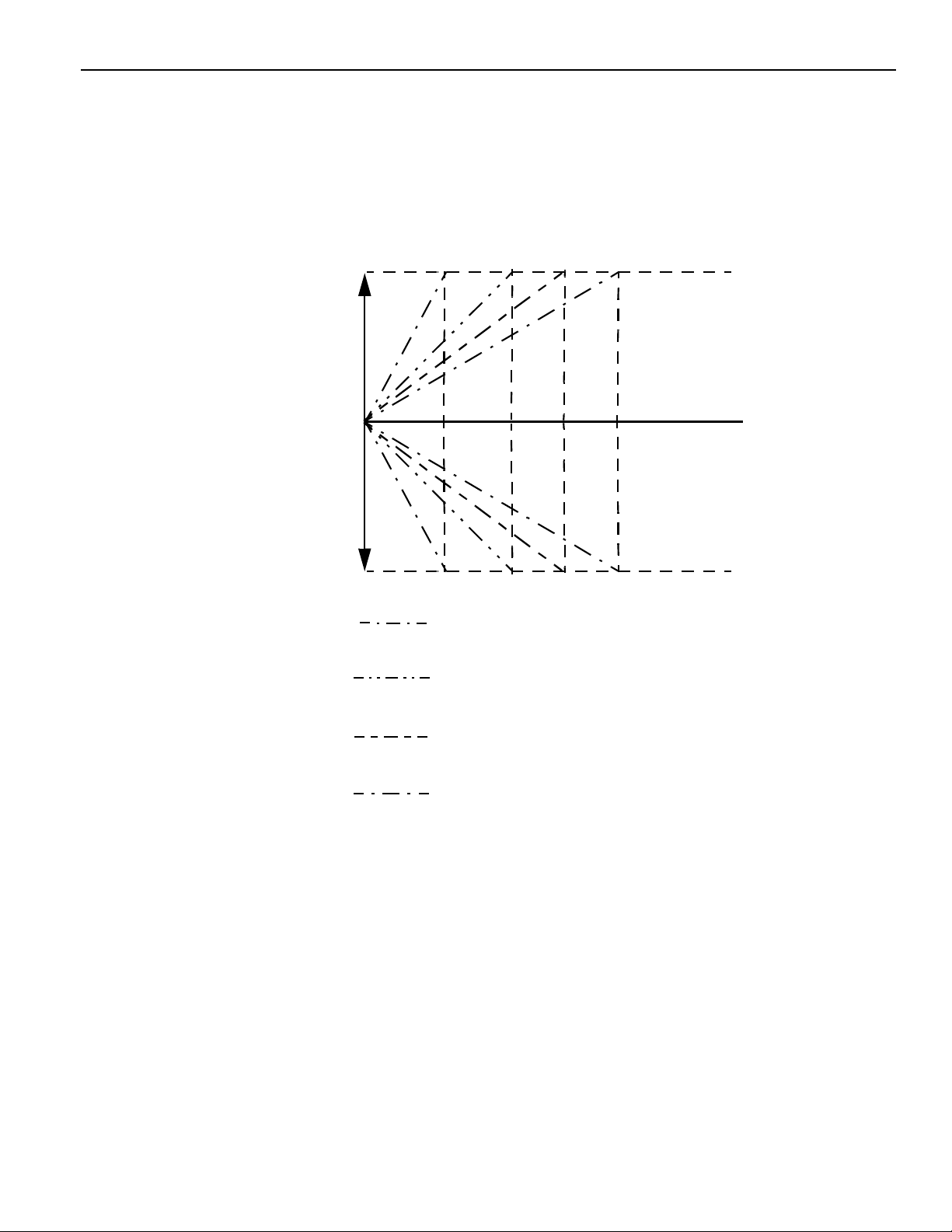
1.6 Rapid T raverse Override Input Signal
Rapid Traverse Override Input Signal ROV1 to ROV4 #30034 to #30036
The rapid traverse override input signal determines the rapid traverse rate used in the execution
of positioning in automatic operation of CNC program, and also for manual rapid traverse
operation with the RT input “closed”.
IMPORTANT!
ROV4 can only be use d when the extension ov erride function (optio n) is sel ec ted.
Input Signals and Rapid Traverse Rates
Input Signal Rapid Traverse Rates
ROV4 ROV2 ROV1 No. 1 Axis No. 2 Axis No. 3 Axis No. 4 Axis No. 5 Axis
0 1 1 Feedrate set
for pm2801
0 1 0 (Feedrate set for
pm2801) x 1/2
0 0 1 (Feedrate set for
pm2801) x 1/4
00 0F
10 0F
10 1F
pm2801 to pm2805 x pm2447 (%), or traverse set for pm2447 (see Note 2)
0
pm2801 to pm2805 x pm2448 (%)
0
pm2801 to pm2805 x pm2449 (%)
0
Note 1: The status of signals is indicated by “0” or “1”.
0: Open
1: Closed
Note 2: Interpretation of the val ue set fo r ppm 2447, used for determining the traverse rate F
is indicated below.
pm2000 D3= 0: The uni ts of the value set forpm2447 are “mm/min.”.
pm2000 D3= 1: The uni ts of the value set forpm2447 are “%”.
Feedrate set for
pm2802
(Feedrate set for
pm2802) x 1/2
(Feedrate set for
pm2802) x 1/4
Feedrate set for
pm2803
(Feedrate s et for
pm2803) x 1/2
(Feedrate s et for
pm2803) x 1/4
Feedrate set for
pm2804
(Feedrate se t f or
pm2804) x 1/2
(Feedrate se t f or
pm2804) x 1/4
Feedrate set for
pm2805
(Feedrate set for
pm2805) x 1/2
(Feedrate set for
pm2805) x 1/4
0
1 - 8
Page 16

YASNAC PCNC I/O Signal Function Manual Chapter 1: Feed Function
1.7Manual Feed Axis/Direction Selection Input Signal
+X to +5 #30710 to #30714
Manual Feed Axis/Direction Selection Input Signal
-X to -5 #30720 to #30724
The manual feed axis/direction selection input signals determine the direction of axis movement
and the axis to be m oved when the CNC is in t he jog mode, rapid traverse mode or manual step
feed mode.
When the “+” or “-” signals are “closed”, the correspondin g axes are move d. I f more than one
axis is selected, simultaneous axis movement is possible for up to the designated number or
simultaneously controllable axes.
IMPORTANT!
If both the “+” or “-” sig n als of the selec ted axis are “closed” or “opened” at the
same time, the axis cannot be moved. If this occu rs during axis movement, the axis
decelerate s and stops.
1 - 9
Page 17

YASNAC PCNC I/O Signal Function Manual Chapter 1: Feed Function
1.8 Solid Ta p
Solid Tap Mode G93M #35381
Spindle Position Loop Command SLPC #31174
Spindle Position Loop Mode SLPS #36512
Solid Tap Gear Selection STPGR #31155
(1) Solid Ta p Mod e Signal
The output signa l is in respon s e to the execution. At th e machin e, the spin dle start ( fo r w ard)
signal should be “opened” at this signal. Then return the spindle positin control loop command
input signal (SLPC ) aft er confirming that the spindle has been stopped by t he spind le ze rospeed signal.
IMPORTANT!
1. If the spindle controller has a soft start circuit, cancel it at the same time when the SLPC is
“opened”, since acceleration an d deceleration are controlled by the NC.
2. All of the following input signals must be “closed”.
Spindle reverse rota tion (SINV)
Gear shifting (GRO)
Spindle fixed speed (SO R)
(2) Spindle Position Loop Command
The signal is used to con fig ure the spindle position control loop in the NC.
When thi s input si gn al is “opened”, the CNC configur es the position control loop for the
spindle after confi rm ing that the spindle has stopped. It th en re turns the spindle positio n
control loop mode ou tp ut signa l (SL PS).
(3) Spindle Position Loop Mode Output Signal
The output signa l oc curs when the CNC has set the posit i on control loop for the spi ndl e t o
execute so l id tapping.
The executio n of the G93 block is com pleted by the outpu t of t his sig nal.
1 - 10
Page 18
YASNAC PCNC I/O Signal Function Manual Chapter 1: Feed Function
(4) Solid Tap Gear Selection Signal
For the machin e equipped withtw0-step gear range , it is possible to execute solid tapping in
both gear ranges A and B (Low and High ). When the signal is “open”, the A gear range is
selected, and when it is “closed”, the B gear range is se lected.
The signal must be set before the designation of the G93 (solid tap command) block. Once set,
the signal status must not b e changed until the solid tap mode is cancelled.
(5) Time Chart for Solid Tap Operation
Solid tap mode
G93 block G94 block
CNC program
G93M
Machine
Side
SUPPLEMENT
1. The G93M signal is “opened” when the G93 block is executed with both the dry run and MST
function lock OFF.
2. The G93M signal is “closed” when the execut io n of the G94 block starts or the CNC is reset.
Spindle start
(forward)
SLPC
Internal
processing (NC)
SLPS
Spindle
indexing
3. The G93 block is assumed to have been completed when the SLPS is “opened”, and the pro-
gram advances to the next block.
4. The G94 block is assumed to have been completed when the SLPS is “closed”, and the pro-
gram advances to the next block.
1 - 11
Page 19

YASNAC PCNC I/O Signal Function Manual Chapter 2: Saving And Editing Programs
2
SAVING AND EDITING PROGRAMS
Chapter 2 describes the signa ls for stori n g and e ditin g programs.
This Page is left Blank Intentionally.
2 - 1
Page 20

YASNAC PCNC I/O Signal Function Manual Chapter 3: Operation And Display
3
Operation And Display
Chapter 3 describes the signals related to operation and display.
3.1 Calendar Output Signal. . . . . . . . . . . . . . . . . . . . . . . . . . . . . . . . . . . . . . . . . . . . . .3-2
3 - 1
Page 21

YASNAC PCNC I/O Signal Function Manual Chapter 3: Operation And Display
3.1 Calendar Output Signal
Calendar Output Signal CALEN1 TO CALEN4 #35064 TO #35067
By comparing the internal calendar of the CNC with the parameter (date) setting and by
out-pu tting the result of the comparison, it is possible to dispa ly a message such as a regular
maintenance warni n g by using the sequence program.
The calendar is in the CNC. By comp ari ng the ca le ndar t o the data par amete r sett in g, th e
result of the comparison is output. If the parameter setting is smaller than the CNC calendar
value, the signals (CALEN1 to CALEN4) are output corresponding to the pa ram eter used
for comparison.
For such processing, up to fou r parameters can be used to save the ca le ndar data.
The following shows an example of calendar data settin g for a parameter:
pm0905 = 19961 020 (October 20,1996)
pm0906 = 19960 301 (March1,1996 )
(1) Calendar O utput Signals (CALEN1 to CALEN 4)
The follow in g table shows th e relationship between the CNC calendar and the calendar signals to be output.
Signal Description
#35064 The status of No. 1 calendar
*Output when the CNC calendar data exceed the setting for pm0905
#35065 The status of No. 2 calendar
*Output when the CNC calendar data exceed the setting for pm0906
#35066 The status of No.3 calendar
*Output when the CNC calendar data exceed the setting for pm0907
#35067 The status of No. 1 calendar
*Output when the CNC calendar data exceed the setting for pm0908
3 - 2
Page 22

YASNAC PCNC I/O Signal Function Manual Chapter 3: Operation And Display
(2) Calendar Status
The relationship between the CNC calendar data and a parameter setting is indicated below.
Parame ter Value I/O
19960714 1
19960715 0
1995999 1
2000000 0
Since the calendar da ta tre at e d as bi nary data, comparison is possible even if the mo nt h value
exceeds “12”or day value exce ed s “31”.
For example, if the setting for a parameter is “19999999”, and if the CNC calendar data is
“19960715” (July 15 ,1 996), comparison is made as indicated below.
<
19960715 - 19999999
0
=
Since the result of compari son is negative, the output i s “0” (status of the calendar).
T o clear the calendar status, reset an appropriate value for a calendar parameter. When a
value greater than the CNC calendar data is et, t h e s tatus of the calendar is cleared.
The parameters used as the calendar parameter are indicated below.
pm0905 No. 1 calendar parameter
pm0906 No. 2 calendar parameter
pm0907 No. 3 calendar parameter
pm0908 No. 4 calendar parameter
3 - 3
Page 23

YASNAC PCNC I/O Signal Function Manual Chapter 4: M, S, T, and B Functio ns
4
M, S, T And B Functions
Chapter 4 desribes the signals for M, S, T, and B functions.
4.1 Input/Output Signals of M. S, T and B Code s4-2
4.2S5-Digit Command Input Signal4-5
4.3 Gear Range Se le ct ion Input and Output Signals4-9
4.4 Gear Shift Input and Spindle Fixed Speed Input Signals4-11
4.5 Spindle Speed Agre ed Input Signal4-12
4.6 Spindle Speed Override Input Signal s4-12
4.7 Binary Comma nd Input Signals4-14
4 - 1
Page 24

YASNAC PCNC I/O Signal Function Manual Chapter 4: M, S, T, and B Functio ns
4.1 Input/Output Signals of M,S,T and B Codes
(1) M, S, T and B Code Output Signals and M, S, T and B Code Re a d O ut put Signals
M code output MA0 to MA9 #35200 to #35211
S code output SD00 to SDO23 #36540 to #36567
Tcode output TO to T19 #35300 to #35323
B code output B0 to B15 #35330 to #35347
M code read output MF #35350
S code read output SF #36517 T code read output TF #35357 B code read output BF #35355
Kinds and Addresse s of M, S, T an d B Code Output Signals & Read Output Signals
These are output sign al s for the M, S, T and B commands specified in a program.
If a M, S, T and B command is read during the execution of a part program in the automatic
mode, then CNC outputs the signals according to the numeric value specified with address
M, S, T or B.
Then, the M, S, T or B code read ou tput sig nal is “closed” after the e lapse of the time se t fo r
a parameter.
IMPORTANT!
In the case of an S4 digit comm an d, an S cod e sig na l an d S code read signal are not outpu t
since the output is a 12 bit no-c ont act output or analog out put for a S4 digi t command.
1.M commands for logic circuit processing (M90 to M99)
Neither M code nor MFA code is output. M codes are those for interna l processing of the
CNC, and accordin gly, they cannot be used as external M codes.
2.M decode output signa ls (M00R, M01R, M02R and M30R)
Among the M codes, if M00, M01, M02 or M30 is executed, the corre sponding M decode
output signals (M00R(# 35214); M01R(#35215); M 02R(#35216); M30R( #35 217) appear
in addition to the M code and M code read output signals. The M decode output signal is
“opened” at th e start of automatic operation or when the CNC is res et.
If an M command with a dec ode out put signal is specified to gether/along with an a xis
movement com m and in the same block, the M de code output signal appe ars only after the
4 - 2
Page 25
YASNAC PCNC I/O Signal Function Manual Chapter 4: M, S, T, and B Functio ns
completion of the specified axis movement although th e M code out put signal ap pears at
the start of the execution o f th at block.
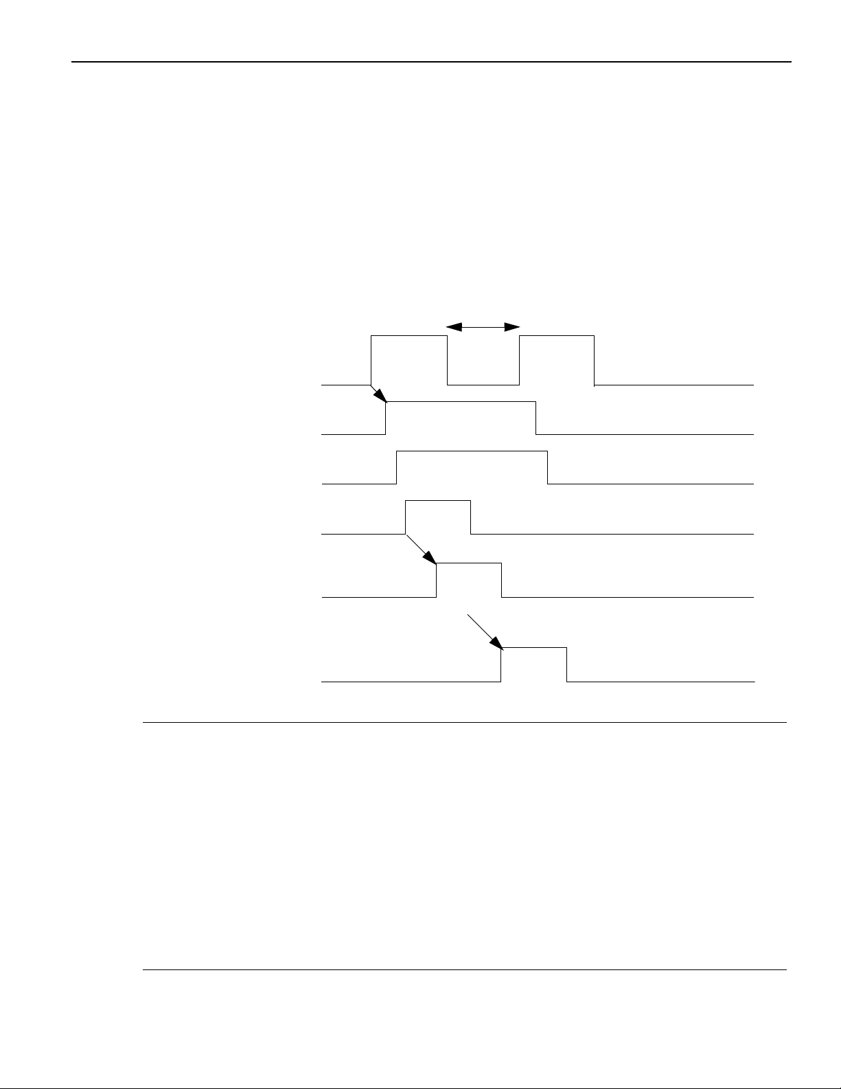
An example of the M decode ou tpt is shown in Fig. 4.1.
Axis movement
command
M code output
M decode output
DEN
FIN
Cycle start or
restart signal
Fig. 4.1 M Decode Output Time Chart
(2)M, S, T and B Function Completion Inut Signals
These input signal s indicate the com leti on of a M,S,T or B command to the CNC.
Output sign als MF, S F,TF and BF are “opened” if input signal FIN is “closed” while th e M,
S, T and B code read (MF A, SF,TF and BF) output signal is “open”. Then, when input signal
FIN is “opened” after the confirmation of “opening” of the output signal, the CNC assumes
that the execution of M,S,T or B command has been competed and execures t h ye next step
operation.
IMPORTANT!
1. The M code outptu signal is “opened” when the status of input signal FIN changes
from “closed” to “open”. For the S, T and B code outptut signals, the “open” or “closed ”
state is maintained.
2. For T and B codes, there are only bunary outputs and BCD outputs are not given.
4 - 3
Page 26
YASNAC PCNC I/O Signal Function Manual Chapter 4: M, S, T, and B Functio ns
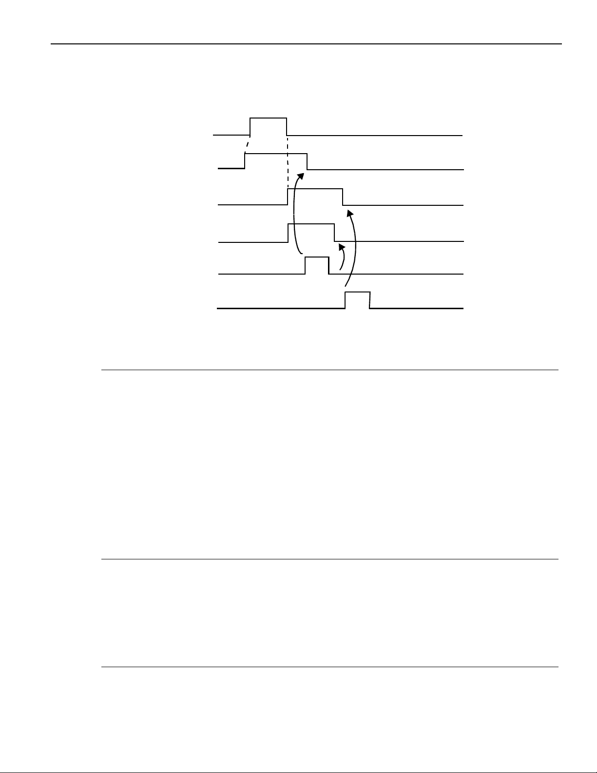
(3)Time Chart of M, S, T and B Signals
(a) When an M command is specified:
M code output
DEN
Read output
FIN input
Fig. 4.2 M Code Signal Time Chart
(b) When an S,T and/or B com m an d is spe ci fied
To the next step
Fig. 4.2 S/T/B Code Signal Time Chart
(c) When M/S/T/B command is specified with a n axis movement comma nd in the same
block.
4 - 4
Page 27

YASNAC PCNC I/O Signal Function Manual Chapter 4: M, S, T, and B Functio ns
If an M/S/T/B command is specified along with an axis movement command in the same
block, the M/S/T/ B command is ex ec ut ed simultaneously with the axis move me nt.
Axis movement
To the ne xt st ep
M code output
M code read output
FIN input
Fig. 4.4 M/S/T/B Code Signal Time Chart when Specified with
an Axis Movement Command in the Same Block
4 - 5
Page 28
YASNAC PCNC I/O Signal Function Manual Chapter 4: M, S, T, and B Functio ns
4.2 S5-Digit Command Input Signal
S Code Analog Output Inverse Input SINV #31104
S Code Analog Output Status Output SINVA #36500
Spindle Gear Range Input GR1 to GR4 #31100 to #31103
The CNC outputs these signals to determine the rotation speed of the spindle motor for “S5-
digit non-cont ac t ou tpu t” or “S5-digit analog outpu t” signals.
GR1 to GR4 (#31100 to #31103) signals input the statu s of gea r ra nge to t he CNC to determine the spindle m otoe speed accordi ng to the sp indle speed specified in a pa rt program.
Input signal SINV is used to invert the polartiy of the analog output signal for the S5-di gi t
analog output spe ci fication.
The M04s (#3538d0) is “opened” at the start of the M03 command, and i t is “closed” at the
start of the M04 command.
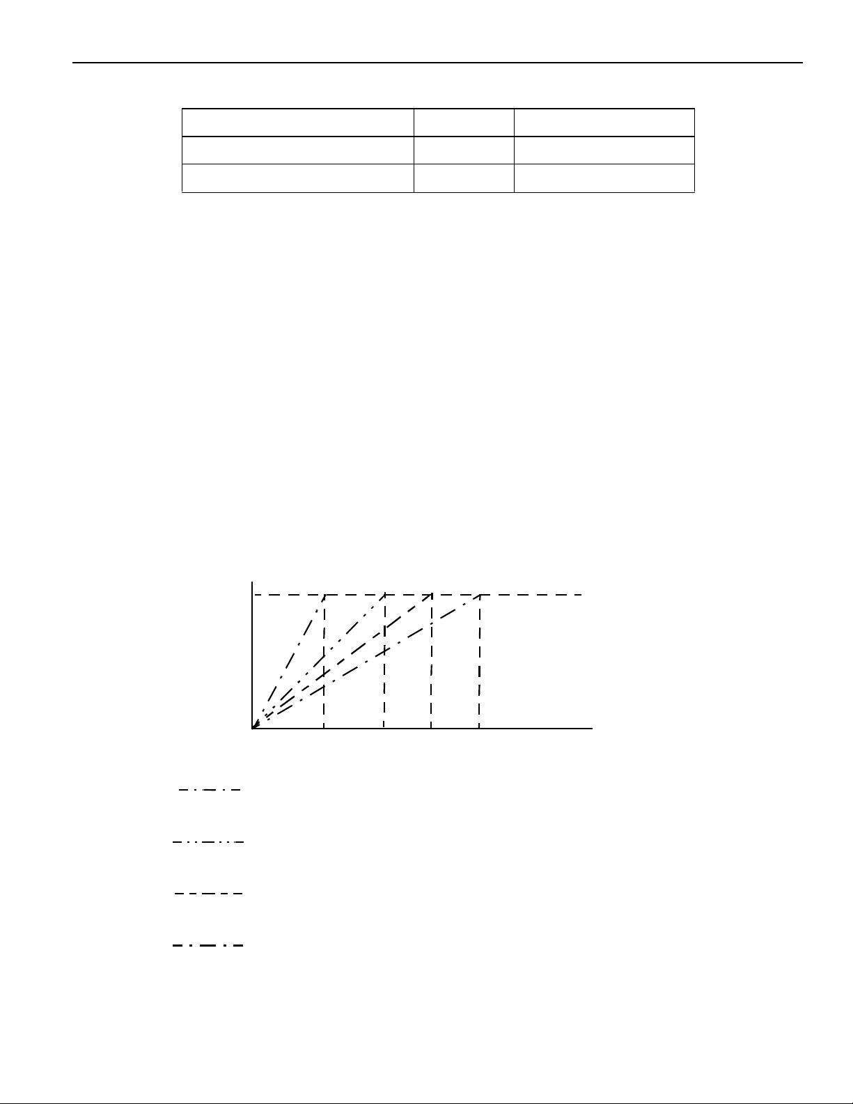
(1) 24-bit Non-contact Output for S5-digit Command
In response to the specifi e d sp in dle spe ed a nd th e gear range input (GR1 to GR4), a 23-bit
binary code (0 to +8 388608: spindle speed ) is out put as show n in Fig. 4.5.
.............................................................................................................................
Spindle Motor Speed
Command Output
8388608
.
Spindle Speed
GR1REV GR2REV GR3REV GR4REV
Fig. 4.5 Non-contact Output for S5-digit Command
: Output when GR1 is “closed”.
The saturated spindle m ot or speed of gear range “GR1”
shoul d be
set for parameter pm1408.
: Output ehen GR2 is “closed”.
The saturated spindle m otor speed of gear range “GR2”
shoul d be
set for parameter pm1409.
: Output ehen GR3 is “closed”.
The saturated spindle m otor speed of gear range “GR3”
S Command
4 - 6
Page 29
YASNAC PCNC I/O Signal Function Manual Chapter 4: M, S, T, and B Functio ns
(2) Analog Output for S50-digit Command
In response to the specif ie d spindle speed and the gear range input (SINV), anal og voltage
(-10V to 0V to +10V) is ou tp ut a s shown in Fig. 4.6.
Spindle Motor Speed
Command Output
+10V
0V
-10V
GR 1REV GR2REV GR3REV GR4REV
Spindle Speed
S Comm an d
: Output when GR1 is “closed”.
: Output ehen GR2 is “closed”.
: Output ehen GR3 is “closed”.
: Output ehen GR2 is “closed”.
Fig. 4.6 Analog Output fo r S5-di gi t Command
4 - 7
Page 30

YASNAC PCNC I/O Signal Function Manual Chapter 4: M, S, T, and B Functio ns
(3) Time Chart of SINV Inut and SINV Ouput
Analog voltage
output
Plus
Minus
100 msec. or shorter
Fig. 4.7 Time Chart of SINV Inut and SINV Ouput
(4) Spindle Speed Clamp
It is possible to set the maximum and minimum spindle speed with parameters for each
of the gear ranges.
Setting the Maximum and Minimum Spindle Speeds
Parameter Description Nos. in
Chart
pm1404 Max. spindle speed when “GR1” input is “closed” pm1405 Max. spindle speed when “GR2” input is “closed” pm1406 Max. spindle speed when “GR3” input is “closed” pm1407 Max. spindle speed when “GR4” input is “closed” pm1400 Max. spindle speed when “GR1” input is “closed” pm1401 Max. spindle speed when “GR2” input is “closed” pm1402 Max. spindle speed when “GR3” input is “closed” pm1403 Max. spindle speed when “GR4” input is “closed”
ú
÷
ø
í
ó
ì
ö
An example of S5-digit analog output signa ls which are clamped by the set maximum and
minimum spindle speed is shown in Fig. 4.8.
4 - 8
Page 31

YASNAC PCNC I/O Signal Function Manual Chapter 4: M, S, T, and B Functio ns
Spindle Motor Speed
Command Output
+10V
.
0V
Output when
SINV input is
“closed”
GR1REV GR2REV GR3REV GR4REV
ó
ú
÷
öø
í
Spindle Speed
Command
Fig. 4.8 S5-digit Analog Outputs Clam pe d by th e Maximum and Minimum Spindle
Speeds Param Setting
IMPORTANT!
1. The spindl e mot or speed command ou tpu t is c al cu la te d by t he following formu la:
(Spindle speed command) x (223 or 10V)
Spindle gear ramge determined by the
Or, spindle speed that corresponds to 10V out put: #1408 to #1411
2. When analog si gn als appear for the spindl e motor, the polar ity can be changed by internally processing M03 (spindle forward rotation) a nd M04 (spindle reverse rotatio n) by
the NC.
4 - 9
Page 32

YASNAC PCNC I/O Signal Function Manual Chapter 4: M, S, T, and B Functio ns
4.3 Gear Range Selection Input and Output Signals
Gear Range Selection Command Output GR1S to GR4S #36504 to #36507
S Function Finish Input SFIN #31117
When an S command is executed, the CNC checks the maximum speed commands of the
individual gear ranges while at the same time it out puts the SF, an d then outputs the gear
selection co mman d (GR1S to GR4S) meet in g th e secified S command.
It then compares the pre s ent gear rang e and returns the FIN if the pres ent gear rang e i s the
same as th e out put gear sele ct ion command. If the gear range must be chang ed, the CNC
enters the gear rang e sel ec t ion sequence. If a fixed speed ou tp ut i s necessa ry for changing
the gear range, the CNC closes the GRO. The CNC outputs the fixed speed signal by giving
top prio rity to this signal.
“Open” the gera range se lection inut signa l ( G R1 to GR4 ) b efore the completi o n of gear
range selection and return the S gear range selection finish (SFIN) at the completion of gear
selection range. The specified spindle speed com m a nd is then output as the non -contact or
D/A output signal.
Then return the FIN when spindle speed agrees with the specified spindle speed.
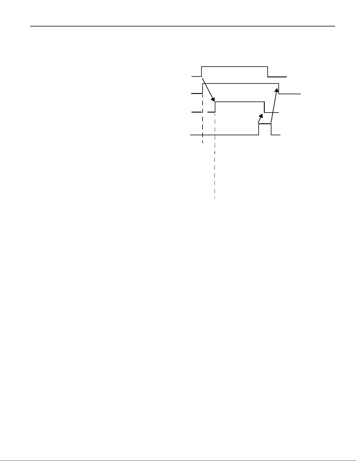
(1) Gear Selection Sig na l Out put Timing
When an S command is re ad, the contro ller judges whether or no t th e gear range must
be changed and exceutes necessary range selection automatically. How this is exceuted
is shown in the time chart shown in Fig. 4.9.
In this example, gear range of GR@ is selected by the commands of “S1000 M03” and
a new spindle speed command “S2000” is specified which requires the gear range to be
changed to GR 3.
SEQUENCE:
1.The CNC judges tha t ge a r ran ge must be changed to GR 3 and and outputs GR3S signal .
2.At the machine side, this signal (GR3S) should be read by the read-command SF which
has a time delay of “t”, and the gear range should be changed. If the spindle motor must be
rotated to execute gear range change, “open” the GRO.
3.After the com pletion of gear range changing to GR 3, “open” GR3 input and then “open”
SFIN (S command finish in put ).
4.At the time the SFIN is “opened”, a new S command is calculated and sent.
4 - 10
Page 33

YASNAC PCNC I/O Signal Function Manual Chapter 4: M, S, T, and B Functio ns
5. ............................................................................................................................. FIN
should then be “opened” when actuall spin dle s peed agr ees wi th th e sp ecif ied s pin dle spe ed
(S2000, in this example).
Block in which a new
S command is specified
GR1S to Gr4S
Spindle gear range
specification out put
Read instruction
t
Gear range selection
operation (GRO input)
S command finish input
MSTcommand finish input
vo
DA output
Spindle gear rang e input
Fig. 4.9 Gear Range Sel ection Signal Outp ut Timing
SF
(GRO input)
SFIN
FIN
SM or VM
GR3
4.4 Gear Shift Input and Spindle Fixe d Spe ed Input Signals
Gear Shift Input Signal GRO #31107
Spindle Fixed Speed Input Signal SOR #31106
These input signals are used to output an S command (other than the one specified) in a
4 - 11
Page 34

YASNAC PCNC I/O Signal Function Manual Chapter 4: M, S, T, and B Functio ns
part program as analog or non-contact output si gna l for an S5-digit command.
If GRO input is “closed”, the vo lt age set f or pa rameter pm1413 is ou tput.
If SOR in put is “closed”, spindle speed set for parameter pm1412 resulting from the
spindle gear ran ge i nput and spindle moto r speed command vol ta ge that correspond to
the gear ranges, is out put .
Setting of GRO and SOR Input Signals
GRO
Input
0 0 Voltage corresponding spindle speed specified in CNC program 0 1 Voltage set for parameter pm1412 1 0 Voltage set for parameter pm1413 1 1 Voltage set for parameter pm1413, 0 V
SOR
Input
Analog Voltage for S5-digit Command
Note: The status of signals is indica ted by “0” or “1”.
0: Op en
1: C losed
IMPORTANT!
1.It is possible to invert the voltage command (analog output for GRO, SOR input) by the
input of a S5-digit analog output inversion (S IN V#31104) input signal.
2.The length of time in wh ic h an analog voltage value responds to the setting of t he G RO
and SOR inputs is less than 100msec .
4.5 Spindle Speed Agreed Input Signal
Spindle Speed Agreed Input Signal SAGR #31116
If the CNC specific a ti on is a S5 -di git analog command or non-contact outpu t, thi s inp ut
signal in dicates that the spindle speed has reached the specified speed at the point where
cutting s tarts during the execution o f a p art program in auto matic mo de.
When cutting should sta rt (axis fee d m ode is changed from the positioni ng m ode to an
4 - 12
Page 35

YASNAC PCNC I/O Signal Function Manual Chapter 4: M, S, T, and B Functio ns
interpolation mo de), the CNC starts cutting aft er confirm ing that the SAGR inp ut signal
has been “closed”.
4.6 Spindle Speed Override Input Signals
Spindle Speed Override Input Signal SPA to SPE #31110 to #31114
If the CNC specific a ti on is a S5 -di git analog command or non-contact outpu t, the
spindle speed overri de input signal is used to overr ide an S-command specifi ed in a part
program in the range from 50 to 120%.
Spindle Speed Override Input Setting and Override Values
SPA Input SPB Input SPC Input Override
Value
11150% 01160% 01070% 11080% 10090% 0 0 0 100% 0 0 1 110% 1 0 1 120%
Note: The status of signals is indica ted by “0” or “1”.
0: Open
1: Closed
20-step override spec ification is optiona l.
Spindle Speed Override Input Setting and Override Values
SPA Input SPB Input SPC Input SPD Input SPE Input Override
Value
0001010%
0011020%
4 - 13
Page 36

YASNAC PCNC I/O Signal Function Manual Chapter 4: M, S, T, and B Functio ns
SPA Input SPB Input SPC Input SPD Input SPE Input Override
Value
0111030%
1111040%
1110050%
0110060%
0100070%
1100080%
1000090%
00000100%
00100110%
10100120%
10110130%
10010140%
10010150%
01010160%
01011170%
01001180%
00001190%
10001200%
Note: The status of signals is indica ted by “0” or “1”.
0: Open
1: Closed
IMPORTANT!
In a tap cycle in the solid ta p mo de , spi ndl e override is invalid if override value is fixed at
100%.
4.7 Binary S Command Input Signals
Binary S Command Input Signals SDI0 to SD123 #36540 to #36567
These input signals are used to specify spindle spe ed i n a 24-bit digital signal instea d of
analog voltage.
4 - 14
Page 37

YASNAC PCNC I/O Signal Function Manual Chapter 4: M, S, T, and B Functio ns
Note:Although the resol ut ion of the CNC is 24 bits, the resolution is restricte d by th e
input resolution of the spindle drive where the binary S command signal is output.
4 - 15
Page 38

YASNAC PCNC I/O Signal Function Manual Chapter 5: Coordinate Systems
5
Coordinate Systems
Chapter 5 describes the signals related to the coordinate system.
5.1 Reference Point Return Control Input/Output Signals. . . . . . . . . . . . . . . . . . . . . .5-2
5 - 1
Page 39

YASNAC PCNC I/O Signal Function Manual Chapter 5: Coordinate Systems
5.1 Reference Point Return Control Input/Output Signals
Reference Point Return Input Signal ZRN #30070
Reference Point Return Deceleration LS *DCX to *DC5 #30730 to #30734
Second Reference Point Return Input Signal ZRN2 #30071
At the Reference Point Output Signal ZPX TO ZP5 #36300 TO #36304
At the Second Reference Point Output Signal 2ZPX to 2ZP5 #36310 to #36314
At the Third Refere nce Point Output Signal 3ZPX to 3ZP5 #36320 to #36324
At the Fourth Refe rence Point Output Signal 4ZPX to 4ZP5 #36330 to #36334
These are input/ou tput signals used for the return function which positions the axes at the predetermined reference point when the CNC power is turned ON.
(1) Reference Po i n t R eturn Methods
For the execution of th e reference point retu rn, the fol lowing methods are provided:
Grid type
High-speed type
(a) Grid type Reference Point Return
With this method, the reference point is determined by the zero-point pulse of the position
encoder (1 pulse/turn).
After turning the CN C power ON, close the ZRN input with the manual jog operation
mode or rapid fee d mo de, and move the axis in th e refe re nce point return direct ion.
Then, the reference point return operation is executed in the sequence as shown in Fig.
5.1.
The G28 command in automatic mode is ex ecuted in the same manner as above.
Feedrate Rapid traverse (pm2801 to pm2805)
Decel. point
Approach speed (pm2521 to pm2525)
Creep speed (pm 2531 to pm2535)
Moved distance (pm4451 to pm 4455)
Feedrate sequence
Dog
width
(*DECX, *DECY, *DECZ, *DEC4, *DEC5)
Feedrate LS signal
Zero-point pulse
Fig. 5.1 Reference Point Return Sequenc e (Grid type)
5 - 2
Page 40

YASNAC PCNC I/O Signal Function Manual Chapter 5: Coordinate Systems
(b) High-speed type reference point ret urn
When the high-sp ee d ty pe (automatic, amunual) is selected, once the reference poi nt
return is executed, the second and later reference point returns are exe cuted by the
positioning mode to the reference point which is determined in the f irst reference
point operation.
Feedrate Rapid traverse
Feedrate sequenc e
Fig. 5.2 Reference Point Return Sequence
(High-speed type, Seco nd a nd Later Operation)
SUPPLEMENT
By setting parameters pm 4003D6 and D7, it is possible to select the gri d typ e for the se cond and
later reference poin t re tu rn ope rations.
(2) Reference Poi nt R etu r n S ig n als
The reference poi nt retu rn sig na ls are de scri bed as follows:
(a) Second reference point retur n input signal
When the second refe re nc e point is ste by the shift amount from the first refere nc e point.
(b) At the reference point output signal
When a nu me rica ll y co n tro lled a xis e xi sts at th e ref eren ce po int as a res ult of t he r efe r ence
point return operation or the positioning to the reference point, the co rre sponding output
signals (ZPX to ZP5) are closed. Note that the output signal is closed only when the corresponding axis ex it s in th e ra nge of +
3 pulse s f r om the refe rence po int posit io n.
(c) At the second r eference point ou tput signa l
In the automatic operation, when an axis is positioned at the second reference point by the
executio n of the “G30” command in a par t pro gra m, the corresponding out put signals
(2ZPX to 2ZP5) ar e cl o s ed to indicate that the axis is at the second reference point.
5 - 3
Page 41

YASNAC PCNC I/O Signal Function Manual Chapter 5: Coordinate Systems
(d) At the third reference point output signal
In automatic operation, when an axis is positioned at the third reference point through the
executio n of the “G30 P3” command in a part pro gram, the correspondi ng out put signals
(3ZPX to 3ZP5) are closed indicating that the axis is at the third reference point .
(e) At the fourth reference point output signal
In automatic opera tion, when an axis is posit ioned at t he four th refer ence poi nt thro ugh the
executio n of the “G30 P4” command in a part pro gram, the correspondi ng out put signals
(4ZPX to 4ZP5) are closed indicating that the axis is at th e fo u rth refere nce point.
5 - 4
Page 42

YASNAC PCNC I/O Signal Function Manual Chapter 6: Operation Support Functions
6
Operation Support Functions
Chapter 6 describes the signals related to the operation support functions
6.1 Input and Output Signals of CNC Operation Modes . . . . . . . . . . . . . . . . . . . . . . .6-2
6.2 Manual Jog Feedrate Selection Input Signals. . . . . . . . . . . . . . . . . . . . . . . . . . . . .6-7
6.3 Manual Pulse/Step Mulitplication Ratio Setting Input Signals . . . . . . . . . . . . . . .6-9
6.4 Automatic Operation Start/Stop Input Signals
and Running/Stopped Output Signals. . . . . . . . . . . . . . . . . . . . . . . . . . . . . . . . . . .6-10
6.5 Single-Block Input Signal. . . . . . . . . . . . . . . . . . . . . . . . . . . . . . . . . . . . . . . . . . . .6-12
6.6 Manual Absolute Input Signal . . . . . . . . . . . . . . . . . . . . . . . . . . . . . . . . . . . . . . . .6-12
6.7 Display Lock Input Signal . . . . . . . . . . . . . . . . . . . . . . . . . . . . . . . . . . . . . . . . . . .6-13
6.8 Program Restart Input Sig nal . . . . . . . . . . . . . . . . . . . . . . . . . . . . . . . . . . . . . . . . . 6-13
6.9 Dry Run Input Signal . . . . . . . . . . . . . . . . . . . . . . . . . . . . . . . . . . . . . . . . . . . . . . .6-14
6.10 Machine Lock Input Signal. . . . . . . . . . . . . . . . . . . . . . . . . . . . . . . . . . . . . . . . . . . 6-15
6.11 Auxiliary Function Lock Inpout Signal . . . . . . . . . . . . . . . . . . . . . . . . . . . . . . . . .6-15
6.12 Edit Lock Input Signal . . . . . . . . . . . . . . . . . . . . . . . . . . . . . . . . . . . . . . . . . . . . . .6-16
6.13 Automatic Mode Handle Offset Input Signal. . . . . . . . . . . . . . . . . . . . . . . . . . . . . 6-16
6.14 Interruption Point Return Input Signal . . . . . . . . . . . . . . . . . . . . . . . . . . . . . . . . . .6-16
6.15 Optional Stop Input Signal . . . . . . . . . . . . . . . . . . . . . . . . . . . . . . . . . . . . . . . . . . .6-17
6.16 Axis Disconnection Designation Input Signals . . . . . . . . . . . . . . . . . . . . . . . . . . .6-17
6 - 1
Page 43

YASNAC PCNC I/O Signal Function Manual Chapter 6: Operation Support Functions
6.1 Input and Output Signals of CNC Operation Modes
(1) Operation Mode Input Signals
These input signals define the operation modes of the CNC by the programmable controller.
For the CNC, the followi ng eight (8) operation modes are provided.
RT #30000 Manual rapid traverse mode
JOG #30001 Manual jog feed mode
H #30002 Manual pulse handle mode
STP #30003 Manual skip feed mode
MDI #30005 Manual da ta input mode
MEM #30006 Memory mode
Manual mode
Automa tic mode
An operation mode is determined by closing one of these input signals.
(a) RT: Manual Rap id Traverse Input Mode
When the “RT” input signal is “closed” with other “open”, the CNC enters the manual
rapid traverse m o de. In this mode, i t controls axis feed accordin g to the inp ut signal of
the manua l fe ed direction and also the rapid override signal.
(b) JOG: Manual Jog Feedra te Sel ec ti on Input Signals
When the “JOG” input signal is “closed” with other inputs “open”, the CNC enters the
manua l jog feed mo d e. In this mode, it controls ax is feed acc o r ding to th e input signal
of the manual feed dire ction.
(c) H: Pulse Handle Mode Input
When the “H” input signal is “closed” with other inputs “open”, the CNC enters the
pulse handle mode. In this mode, it controls axis feed according to axis selection and
the multiply setting signals by operation of the manual pulse generator.
(d) STP: Manual Step Feed Mode Input
When the “STP” input signal is “closed” with other inputs “open”, the CNC enters the
tape mode. In this mode, operation using CNC tape which is read by the ta pe rea der is
enabled.
By setting the appropriate parame t er, it is possible to inp ut a part program from the
RS-232C interface instead of using the tape reader.
6 - 2
Page 44

YASNAC PCNC I/O Signal Function Manual Chapter 6: Operation Support Functions
(e) MDI: Manual Data Input Mode
When the “MDI” input signal is “closed” with other inputs “open”, the CNC enters the
MDI mode. In this mode, operation using a part program entered by the manual data
input op eration is enabled.
(f) MEM: Memory Mode Input
When the “MEM” input signal is “closed” with other in puts “open”, the CNC enters
the memory mode. In th is m ode, operation by usi ng a part stora ge program stored in
the CNC part progra m memory is enabled.
(2) Operation Mode Output Signals
The operation mode output signa ls in diacte the present CNC mode.
Manual Mode Output Signal MAN #35010
Automatic Mode Output Signal AUTO #35011
(a) MAN: Manual Mode Ouput
This signal is outpu t whe n the CNC is in any of the follow ing states:
H (handle mod e)
STP (manual step mode)
JOG (manual jog mode)
RT (rapid feed mode)
(b) AUTO: Automatic Mode Output
This signal is outpu t whe n the CNC is in any of the follow ing states:
TP (tape mode )
MEM (memory mode )
MDI (manual jog mode)
EDT (progr am edit mode)
6 - 3
Page 45

YASNAC PCNC I/O Signal Function Manual Chapter 6: Operation Support Functions
MEM
(Input)
MDI
(Input)
JOG
(Input)
AUTO
(Input)
MAN
(Input)
Fig. 6 Time Chart of Operation Mode Input and Output Signals
(3) Supplements to Operation Mode Input/Output Signals
The items that must be taken into consideration conce rni ng the operatio n mo de input/output
signals ar e indicated below:
1. If an operation mode input signal other than manual mode input signals is given during the
memory mode operation, the CNC stops execution of a part program after the completion
of the block present ly being execute d.
This is also true duri ng a part program executio n in t he tape or MDI mode.
2. If a manual mode input signal is given during the execution of a part program in the memory mode, the following occ urs:
• Axis movment commands
6 - 4
Page 46

YASNAC PCNC I/O Signal Function Manual Chapter 6: Operation Support Functions
The axes are decelerated and stopped, then the program is interrupted. The remaining
axis movement commands can be continuously executed by turning the automatic start
(ST) inp u t s ignal ON after retu r ning to th e automat ic mode.
• M, S and T commands
These commands are processed depending on the setting for pm 4009D7 (forced FIN
mode selection).
pm4009D7=0 (fo rce d FIN m ode set)
Both the sampling output (MFB to MFE) and the M code output are turned O F F,
and the M S and/or T comm a nd is assumed to have bee n completed. Therefore,
the interrupted M, S and/or T comm ands is not output even when a n automatic
mode is recovered. SPL indicator is not lit.
pm4009D7=1 (fo rce d FIN m ode not set)
The M, S and/or T command is saved and the SPL indicator is lit.
3. If an automatic mode input signal or program edit mode input si gna l is gi ve n w hi le an
axis is moved in a ma nual mode, the ax is is de celerated and stoppe d.
4. An operation mode input is valid if onl y one of the input signal s is “closed”. Under other
status c on ditions , the prev iously selected operation mode remains valid .
If there is no operation mode input signal or if more than one operation mode input signal
is given af ter the power is tur n ed ON, the P CNC ente rs the manual jog feed mode.
MEM
(Input)
TP
(Input)
JOG
(Input)
Operation
Mode of NC
Fig. 6.2 Operation Mode Input Signal
6 - 5
Page 47

YASNAC PCNC I/O Signal Function Manual Chapter 6: Operation Support Functions
5. If a manual operation mode input signal is given while a tapping cycle is executed in auto-
matic mode, the automatic mode is maintained until thread cutting is completed.
(4) System Number Switch Monitor Output Signals
The status (0 to F) of the rotary switch “SW2” on the JCP01 board is output by the system
number switch monitor outp ut signal.
CAUTION
The rotary switch SW2 de fines the CNC operation and must not be changed
without consulting your Yaska w a representative , or the ma chine tool builder.
System Number Switch Functions Table
#35023
to
#35020
0000 0 Normal operation
0001 1 End user parameter change mode
0010 2 Standard/option parameter change mode
0011 3 Not used
0100 4 Ladder program exit mode
0101 5 Not Used
0110 6 Not Used
0111 7 Not Used
1000 8 On-line maintenance mode
1001 9 Software debug mode 1
1010 A Software debug mode 2
1011 B Running test mode
1100 C PCB test mode
Rotary
Switch
Setting
Function
ROM
Check
Watchdog Remarks
áá
áá
áá
áá
á
áá
á
With ladder debug function
With ladder debug function
With ladder debug function
With ladder debug function
These positions must not
be selected since they call
the modes on for Yaskawa.
1101 D Not used
1110 E Operation to check contents in memory
1111 F Total make made (f or maintenance)
Note: Rotar y swit ch settings 8 through F are for the Yaskawa Mode.
6 - 6
Page 48

YASNAC PCNC I/O Signal Function Manual Chapter 6: Operation Support Functions
6.2 Manual Jog Feedrate Selection Input Signal
Manual Jog Feedrate Selection Input Signal JV1 to JV16 #30020 to #30024
These signals determine feedrate for manual jog feed operation.
The manual feedrate is also used for the feedrate when executing a part program in automatic
mode with the dry run function set ON.
JOG mode
JV1 toJV16
Valid in this range
Fig. 6.3 Manua l Jog Fe edrate Time Chart
Manual Jog Feedrate Table
JV1 JV2 JV4 JV8 JV16 Jog Feedrate (Manual Mode)
00000Feedrate set for pm2400
10000Feedrate set for pm2401
01000Feedrate set for pm2402
01000Feedrate set for pm2403
00100Feedrate set for pm2404
10100Feedrate set for pm2405
01100Feedrate set for pm2406
11100Feedrate set for pm2407
00010Feedrate set for pm2408
10010Feedrate set for pm2409
01010Feedrate set for pm2410
11010Feedrate set for pm2411
00110Feedrate set for pm2412
10110Feedrate set for pm2413
01110Feedrate set for pm2414
11110Feedrate set for pm2415
00001Feedrate set for pm2416
10001Feedrate set for pm2417
6 - 7
Page 49

YASNAC PCNC I/O Signal Function Manual Chapter 6: Operation Support Functions
JV1 JV2 JV4 JV8 JV16 Jog Feedrate (Manual Mode)
01001Feedrate set for pm2418
11001Feedrate set for pm2419
00101Feedrate set for pm2420
10101Feedrate set for pm2421
01101Feedrate set for pm2422
11101Feedrate set for pm2423
00011Feedrate set for pm2424
10011Feedrate set for pm2425
01011Feedrate set for pm2426
11011Feedrate set for pm2427
00111Feedrate set for pm2428
10111Feedrate set for pm2429
01111Feedrate set for pm2430
11111Feedrate set for pm2431
Note: The status of signals is indicated by “0” or “1”.
0: Open
1: Closed
SUPPLEMENT
For a rotary axis, jog feedrate can be set 1/10 of the feedrate applied for a linear axis by setting the
parameter as indi cated below.
pm2000 D7=0: Fee dra te set for pm2400 to 2431 are appl ied to both linear and rotar y axe s.
pm2000 D7=1: For a rotary axis, 1/10 of the fee drate set for pm2400 to pm 2431 is applied.
6 - 8
Page 50

YASNAC PCNC I/O Signal Function Manual Chapter 6: Operation Support Functions
6.3 Manual Pulse/Step Multiplication Ratio Setting Input Signals
Manual Pulse/Step Multiplication Ratio Setting Input Signal MP1 to MP4 #30025 TO #30027
These sign als determine axis feed amount per step when the PCNC is in the manual handle
or manual step feed mode.
Manual Handle/Step Multiplication Ratio Setting Table
MP1 MP2 MP4 Manual Step Feed Manual Handle Feed
0 0 0 1 pulse/step
1 0 0 10 pulses/step
0 1 0 100 pulses/step
1 1 0 1000 pulses/step 100 pulses/step
0 0 1 10000 pulses/step 100 pulses/step
1 0 1 100000 pulses/step 100 pulses/step
011
111
Note: The status of signals is in di ca ted by “0” or “1”.
0 : Open
1 : Closed
Do not set
6 - 9
Page 51

YASNAC PCNC I/O Signal Function Manual Chapter 6: Operation Support Functions
6.4 Automatic Operation Start/Stop Input Signals and Running/Stopped Output Signals
Automatic Operation Start Input Signal ST #30030
Automatic Operation Stop Input Signal *SP #30031
Running Output Signal #35370
Stopped Output Signal #35371
(1) Automatic Operation Start Input Signal
By “closing” and the “opening” the ST input signal when the tape, memory, MDI or edit mode
is selected for PCNC operation, the PC NC starts automatic operation to execute a part p rogram. At the same time, it turns the running STL output signal ON.
Note that input of th e ST signa l is ignored in the following states:
• The PCN C is in an alarm state. (al ar m output o r input err or s ignal is ON).
• Automatic operation st op “*SP” input is “opened”.
• External reset “ERS” input is “closed”.
• The RESET button on the operation panel is “closed”.
• Emergency stop “*ESP” is not closed.
• STL signal is output dur ing automatic opera ti on.
(2)Automatic Operation Stop Input Signal
After start o f automatic operation, the PCNC completes automatic operation and turns the
automa tic start (STL) output signal OFF when any of the follow ing state s is satisfied.
• In the MDI mode, exe c ution of a part program is completed by the ma nually input data.
• Execution of one bl ock of a part program is completed with the single-block (SBK ) in put
is “closed”.
• The end of a program (EOP) input is “closed” by the execution of an M command in a part
program.
(3) Running Output Signal
If the automatic o p eration s top input “SP” is “opened” during auomatic operation, axis move ment, etc. is inter ru pt ed an d the r unn ing oupu t si gna l “STL” is opened. Then, the stopped output signal “SPL” is closed.
The input of auto ma tic operation stop signal is ignored if it is input in the fol lowing state.
• While a thread cut ti ng block is being ex ec uted.
6 - 10
Page 52

YASNAC PCNC I/O Signal Function Manual Chapter 6: Operation Support Functions
(4) Stopped Output Signal
If the automatic o peration s tart inpu t “ST” is “closed” and then “opened” with the automatic
operation stop input “*SP” closed, the stopped output “SPL” is opened and automatic operation is restarted.
The running ou put “ST L ” is cl osed.
Close
STP
Open
Close
STL
Open
Close
*SP
Open
Close
SPL
Open
PCNC status
Halt Running Halt Running
Fig. 6.4 Time Chart of ST and *SP Input Signal s and STL and SPL Out put Signals
IMPORTANT
1. The automatic operation start (ST) and automatic stop (*SP) input signals must be “closed” or
“opened” for more than 100msec. If it is less than 100 msec., such input signals may be
ignored.
2. If automatic operation stop (*SP) input signal is “closed” in the state where the CNC is waiting for the completio n of M, S,T or B c ommands (waiting for “FIN” input), the automatic
stopped (SPL) output signal is turned ON. If M,T or B command complete (FIN) input signal
is “opened”, the PCNC ent ers the autom a tic operation stopped state.
3. The STL is opened in the single-block stop state.
4. The S T L stays closed i n the alarm state (ALM).
6 - 11
Page 53

YASNAC PCNC I/O Signal Function Manual Chapter 6: Operation Support Functions
6.5 Single-Block Input Signal
Single-Block Inp ut Sign al SBK #30060
This input sign al is used to execute a part program block by bloc k in a utomatic operati on.
When the PCNC is in the automat ic mode with SBK input signal “closed”, if automatic operation
is star ted, the PCNC ex ecutes one block of a part prog r a m and stops, the closes the STL ( running,
#35370) output signal.
If the SBK input signal is “closed” during the execution of a part program, the PCNC stops after
the completion of the block presently being executed.
6.6 Manual Absolute Input Signal
Manual Absolute Input Signal ABS #30061
(1) When the Absolute Input Signal is “Open”
Tool path of a part program e xecuted continuously in automat ic mode after manual int e rruption of axis movement is shifted by the manually moved distance.
G90
G01 Z20. 000 F∆∆
X20. 000 Y30. 000
X10. 000 Y40. 000
.
.
.
X20. 000
{
Y30. 000
X10. 000
{
Y20. 000
X10. 000
{
Y40. 000
Fig.6.5 Tool Path in Automatic Mode Operation
X20. 000
{
Y30. 000
X10. 000
{
Y40. 000
X10. 000
{
Y20. 000
Manually operated axis movement
Fig.6.6 Tool Path after Manual Interrupti on (A BS Input Signal “Open”)
6 - 12
Page 54

YASNAC PCNC I/O Signal Function Manual Chapter 6: Operation Support Functions
(2) When the ABS Input Signal is “Closed”
X20. 000
{
X10. 000
{
Y20. 000
Y30. 000
X10. 000
{
Y40. 000
Fig.6.7 Tool Path with ABS Input Signal “Closed”
6.7 Display Lock Input Signal
Display Lock Input Signal DLK #30062
This input signal is used to prevent outp ut of the PCN C to the external po sition display.
If the DL K in put signa l is “closed”, al though axis move ment is executed (both in autom at ic and
manual modes), the position data pf the external position display (CRT, POS display “EXTER-
NAL”) are not updated.
6.8 Program Restart Input Signal
Program Restart Input Signal PRST #30063
This sig n al is used to r estart machinig fr om a desi gn ated point in a part p r ogram.
After “closing” the PRST input signal, select the memory mode and search the number for pr ogram restart at the PCNC operation panel.
The M,S and T codes existing in the blocks from start of the part program to the specifie d
sequence num be r are displayed on the sc reen.
6 - 13
Page 55

YASNAC PCNC I/O Signal Function Manual Chapter 6: Operation Support Functions
6.9 Dry Run Input Signal
Dry Run Input Signal DRN #30064
The input signal uses the manua l jog fe edrate selection input signals (JV 1, JV2, JV4, JV8, JV16)
for the execution of a part program in automatic mode.
When a part p rogram is exec uted in automatic mode w i th the DRN i nput signal “closed”, axis
feed is executed not by the feedrate specified in the part progra m but by the feedrate defi ned by
the man ual jog feed rate selection input signa ls .
If the DRN inp u t s ig n a l changes from “open” to “close” or from “closed” to “open” while the
PCNC ise xecuting automatic operation, feed rate is chang ed a ccording to t he s elected feed mode
as indicated below:
• In the “mm/rev” mode: The feedrate is not changed for the block presently executed.
• In the “mm/min” mode: Th e feedrate is chang ed even during th e execution of commands in a
block.
Note: During the execution of a tapping cycle, the feedrate is not changed during the execution
of commands in a block and a new feedra t e be comes valid after the com pl et ion of the
commands in the block.
Concerning a rapid feed, whether the rapid feedrate or jog feedrate is used can be selected
by the setting for a parameter. If rapid feedrate is selected, rapid feedrate override function
is not va lid.
The acceleration/deceleration time constant is not influenced by whether or not the dry run
is turne d ON.
<Parameters>
• Dry run internal toggl e sw i tc h ON /OFF pm0000 D3
• Valid/invalid dry run for rapid feed pm2000 D0
6 - 14
Page 56

YASNAC PCNC I/O Signal Function Manual Chapter 6: Operation Support Functions
6.10 Machine Lock Input Signal
Machine Lock Input Signal MLK #30066
Axis-depend ent Machine Lock
Input Signal
AMLKX to AMLK5 #30840 to #30844
The machine lock input signal is used to prevent output of the output pulses of the PCNC to servo
units.
The machine lock function is used to check a new program without actually moving the axes.
When the MLK input signal is “closed”, altho ug h t he log ic circui t distributes pulse s , th e axes are
not moved (both in aut om atic and manual mode operations).
Since the logic circuit distributes pulses, the position data is updated as the axis move commands
are executed.
To change the status of the ML K input signal from “closed” to “opened” o r from “opened” to
“closed”, the PCNC must be stopped. In other words, if the MLK input signal stat us should be
changed, the PCNC must be in the Block Stop state or Feed Hold state. If it is changed when the
PCNC is in other states, attempted change is ignor ed.
By using the AMLKX(#30840) to AMLK5(#30844) input signals, the machine lock function can
be called for the individual axes.
If the MLK input signal is “closed” during single-block mode operation, the machine lock function becomes valid afte r the blo ck stops.
6.11 Auxiliary Function Lock Input Signal
Auxiliary Function
Lock Input Signal
The auxiliary fun ct ion lock input signal is us ed to omit the execut ion of the M,S,T and B functions for th e ex ecution of a part program in aut om atic mode.
If the AFL inp ut signal is “closed”, the PCNC ignores the M,S,T and B commands specified in a
part program. The cod e/ de co de output sugnals (M00R, M01R, M02R and M30R) are ou tp ut,
however. Analog D/A signal is also output to the spin dle.
If the AFL input signal status is changed from “opened” to “closed” or from “closed” to “opened”
during the execution of a part program, the program is executed according to the selected AFL
input signal state from the block next to th e one currently bei ng executed.
ALK #30067
6 - 15
Page 57

YASNAC PCNC I/O Signal Function Manual Chapter 6: Operation Support Functions
6.12 Edit Lock Input Signal
Edit Lock Input Signal EDTLK #30072
The edit lock input sig na l pro te ct s part programs stored in the PC NC part program memory from
being altered.
When the ED TL K input signal is “closed”, key operation of the [IN SE T], [ALTER] and
[ERASE] keys, and the data storing opertion are ignored.
If program edit operation is attempted in this stat e, the following warning message is displayed:
“EDIT LOCK!”
6.13 Automatic Mode Handle Offset Input Signal
Automatic Mode Handle
Offset Input Signal
When the HOFS input signal is “closed”, axis m ovement generate d by the pulse handle ca n be
overlapped with the axis m ovement exec ut ed in the automa tic operation.
The axis for which overlapping of axis movement by the pulse handle is the one which
selected by the pulse handle feed axis selection input signal. Axis movement distance
per pulse can be changed by setting th e multiplication ratio setting switch.
IMPORTANT!
1. Axis mov em ent by the automa ti c mode handle offset func ti on is always valid even during
block stop or when a block which does not include axis movement commands is executed.
2. If the axis interlock input (*IT X to * I T5) signa l is “closed”, axis movement by the automatic
mode handle offset function is not possible .
6.14 Interruption Point Return Input Signal
HOFS #30081
Interruption Point Return
Input Signal
CPNR #30082
By moving axes manually after interrupting automatic operation to remove chips or performing measur ements, close the CPRN input signal and the n the manual axis feed direction selection inp ut signa l i n the di rection the axis can mo ve to the point where operation
was interru pted, and the ax is returns to the operation int errupted point.
Note that if the reference point return input or the second reference point return input signal
is “closed”, the axis does not return to the operation interrupted point, but returns to the reference point or t o the second reference poi nt .
6 - 16
Page 58

YASNAC PCNC I/O Signal Function Manual Chapter 6: Operation Support Functions
6.15 Optional Stop Input Signal
Optional Stop Input Signal OPT #30406
The optional stop i nput signal determine s w hether or not the M01 comm a nd should be executed in automatic operation mode (tape, memory, MDI).
• ON: After the execution of the block that includes M01, the PCNC stops with the automatic
operation start (ST) input signal “closed”. This is “opened” when the FIN signal input
is retur ned. Suspen ded oper ation rest arts when the ST signal is “open”.
• OFF: The M01 command is ignored.
The OPT input signal is invalid for the blo ck pr esently executed. If it is give n during automatic
operation, it becomes valid from a newly read block.
6.16 Axis Disconnection Designation Input Signals
Axis Disconnection
Designation Input Signals
DTCH4 to DTCH5 #30833 TO #30834
By using the axis disconnection designation input signals, it is possible todisconnect the
fourth and fifth axes.
For the disconnecte d axies, an alarm is ignored if it occurs to the disconnec t ed axis; the
result is the sam as in the machin e lock state.
IMPORTANT!
1. Axis disc onnection operat ion must be executed only af te r the servo power is turned OF F.
When the axis discon ne ct ion desi gna t ion input signal (DTCH4, DTCH 5) is “closed”
with the servo po wer O N , th e alarm output signa l (AL M ) i s “closed”.
2. When re- inst alli ng an axis which has been disconnected, the power must be OFF and
then ON again.
3. When disconnecting an axis, disconnect th e cable between the AC SERVOPACK
(lamp) and the AC servomotor.
4. If the servo power is turned ON (a fter tu rni ng the servo power ON wi th an axis disconnected), the alarm output signal (ALM) is “closed”.
5. For disconnected axes, over tra ve l i nput signals (*+4 to*+5,* -4 to*-5) are not detected.
6. For disconnected axes, servo power is not turned OFF. Therefore, the servo ON signals
(SVOF4 to SVOF 5) are valid f or s uch axes.
6 - 17
Page 59

YASNAC PCNC I/O Signal Function Manual Chapter 7: Programming Support Functions
7
Programming Support Functions
Chapter 7 describes the signals related to the program mi ng supor t functions.
7.1 Time Count Input Signal. . . . . . . . . . . . . . . . . . . . . . . . . . . . . . . . . . . . . . . . . . . . .7-2
7.2 Optional Block Delete Input Signal . . . . . . . . . . . . . . . . . . . . . . . . . . . . . . . . . . . .7-2
7.3 End of Program Input, Rewind Input and Output Signals . . . . . . . . . . . . . . . . . . .7-3
7.4 System Variable for Interface Input/Output Signals. . . . . . . . . . . . . . . . . . . . . . . .7-4
7.5 Mirror Image Input Signals. . . . . . . . . . . . . . . . . . . . . . . . . . . . . . . . . . . . . . . . . . .7-7
7.6 Canned Cycle Operation Status Monitor Output Signals. . . . . . . . . . . . . . . . . . . .7-7
7 - 1
Page 60

YASNAC PCNC I/O Signal Function Manual Chapter 7: Programming Support Functions
7.1 Time Count Input Signals
Time Count Input Signals EXTC #30051
The time coun t in put signal is used to opera te the external timer for disp la yi ng operating
time while it is “closed”.
The external time counts the duration while the input signal is “closed”.
How the accumulated time is reset differs according to the parameter setting.
Parameter
No.
Bit
No.
0: The timer value is reset when the [0 CLR]
softkey, on the operation time screen , is pr essed.
1: The timer value is reset when this signal state
pm3007 D4
changes from the “opened” state to the “closed” state.
It is possible to reset the accumulated timer data by
using the Reset Button on th e Run | Timers screen.
7.2 Optional Block Delete Input Signals
Optional Block Delete
Input Signals
The optional block delete input signal (B D T) determines whet he r or not the information
between the slash code (/) and the end of block code (EOB) in the block in which the slash
code is specified is val id . Se e Table 7.1.
Description
BDT #30405
BDT2 to BDT9 #30420 to #30427
The sign al is valid in the memory, tape and MDI mo des.
Table 7.1 Optional Block Delete Input Signals and the Information to be Ignored
Signal Information to be Ignored
BDT input signal is “closed” From “/” or “/1” to “EOB”
EDT2 input signal is “closed” From “/2” to “EOB”
EDT3 input signal is “closed” From “/3” to “EOB”
EDT4 input signal is “closed” From “/4” to “EOB”
EDT5 input signal is “closed” From “/5” to “EOB”
EDT6 input signal is “closed” From “/6” to “EOB”
7 - 2
Page 61

YASNAC PCNC I/O Signal Function Manual Chapter 7: Programming Support Functions
Signal Information to be Ignored
EDT7 input signal is “closed” From “/7” to “EOB”
EDT8 input signal is “closed” From “/8” to “EOB”
EDT9 input signal is “closed” From “/9” to “EOB”
IMPORTANT!
1. The pa rt pr ogram informati on is ig nored only when the p art program is executed . Accordingly, this optional blo ck del ete i nput signal does not have influ enc e wh en storing part programs into th e CNC pa rt program memo ry.
2. Whethe r the information is trea t ed a s signi fi cant informatio n or ig nored is determined by the
status of the optional blo ck de l et e in put signal does not have influe nc e w he n sto r i ng pa rt programs into th e CNC pa rt program memo ry.
Therefore, if th e optional block dele te inp ut signal status should be controlled by the ex te rna l
circuit using the auxiliary function, attention must be paid so that the status of the input signal
is established before the block containing the “/” code is stored into the buffer area.
3. If more than one optional block del et e c ode is spec ified in one block, it is treat ed as follows:
Example: When BDT3 input signal is “closed”
/G01 /2 X____/3 Y____/4 Z____/5 F____;
Significant information
insignificant information
4. For a macro program, the optional block delete function cannot be used.
7.3 Optional Block Delete Input Rewind Input Signals, and Rewinding Output Signal
End of Program Input Signal EOP #30410
Rewind Input Signal RWD #30411
Rewinding Output Signal RWDS #35376
(1) End of Program and Rewind Input Signals
These signals determine the processing to be take n by the CNC when the M02 or M30
command is executed.
Processing by the CNC is det ermi ned by the status of the EOP and RWD input signals
when the FIN input signal (the com plete input for M02 or M30) is close d.
7 - 3
Page 62

YASNAC PCNC I/O Signal Function Manual Chapter 7: Programming Support Functions
Status of EOP and RWD Input Signals and Corresponding CNC Processing Table
EOP RWD Processing
1 1 Rewinds the part program and executed program reset.
After that the CNC enters the halt state.
1 0 After exceuting prog ram reset, the CNC enters the halt state.
0 1 After rewinding the program, the CNC enters the halt state
0 0 The CNC enter the halt state.
IMPORTANT!
When the “program reset” is executed, the rese tting output signal RST is maint ain ed “closed” for
one second.
(2) Rewinding Output Signal
This output signa l indic a te d tha t a par t program is being rewou nd.
While a part program is rewound by the RWD input signal, in response to th e M02 or
M30 command, the RWDS output signal remains “closed”.
TERMINOLGY
• Program Reset
The “program reset” is b asically the same as the reset o peration executed by pres sing the
[RESET] soft-key on the PCNC Operation Panel or the reset operation executed in response to
the “closing” of the external reset [ERS] inpu t signal. W ith the “program reset”, however, th e
CNC mem o ry rewind is n ot execut ed. For details of the r es et operation, refer to “Safety and
Maintenance Functions” Section 2 of Chapter 10.
7 - 4
Page 63

YASNAC PCNC I/O Signal Function Manual Chapter 7: Programming Support Functions
7.4 System Variables for Interface Input/Output Sign als
Interface Input Signal U10 to U131 #30460 to #30497
Interface Output Signal UO0 to UO31 #35400 to #30437
(1) System Variables for Interface Input Signals
By entering a system variable for interface sign als at the right part of an opera ti on
expression, the ON / OFF sta te of 32-point input signals specia l fo r ma c ro programs are
read. The re lationship between the input signals and the system variab les is indicated in
Table 7.3.
Interface Input Signals and System Var iables Table
System Variable #1007 #1006 #1005 #1004 #1003 #1002 #1001
Input Sign a l
UI7
2
7
UI6
2
UI5
6
5
2
UI4
2
UI3
4
3
2
UI2
2
UI1
2
1
2
System Variable #1015 #1014 #1013 #1012 #1011 #1010 #1009
Input Sign a l
UI15
15
2
UI14
14
2
UI13
13
2
UI12
12
2
UI11
11
2
UI10
10
2
UI9
2
9
System Variable #1023 #1022 #1021 #1020 #1019 #1018 #1017
Input Sign a l
UI23
23
2
UI22
22
2
UI21
21
2
UI20
20
2
UI19
19
2
UI18
18
2
UI17
17
2
System Variable #1031 #1030 #1029 #1028 #1027 #1026 #1025
Input Sign a l
UI31
31
2
UI30
30
2
UI29
29
2
UI28
28
2
UI27
27
2
UI26
26
2
UI25
25
2
#1000
UI0
0
2
#1008
UI8
8
2
#1016
UI16
16
2
#1024
UI24
24
2
• The values read by the system vari ables indic at ed in Table 7.3 are either “1.0” or “0.0”
depending on wh et he r the corresponding inp ut sig na l is ON or O FF.
Variable Value Table
Input Signal Variable Value
ON 1.0
OFF 0 .0
7 - 5
Page 64

YASNAC PCNC I/O Signal Function Manual Chapter 7: Programming Support Functions
• By entering system va ri abl e #1032 in the right part of t he operation expressi on, it is possi ble
to read the ONN/OFF stat e of the 32 po int s of the inpu t signals (UI 0 to UI31) coll ec tive ly in a
positive de cimal value.
31
#1032 =
i = o
#[1000 + i] x 2
Σ
1
• It is not possible to substitute a numeric value by entering system variables #1000 to #1030 in
the left part of the opera ti on expression.
(2) System Varia ble s for Inter fac e O utput Sig n al s
By entering a system variable for interface signals at the left part of an operation expression, the ON/OFF state of 32-point input signals special for macro programs are set. The
relationship between the output signals and the system variables is ind ic ated in following tabl e.
Interface Output Signals and System Variables Table
System Variable #1107 #1106 #1105 #1104 #1103 #1102 #1101
Input Signal
UO7
7
2
UO6
6
2
UO5
5
2
UO4
4
2
UO3
3
2
UO2
2
2
UO1
1
2
S ystem Va riable #1115 # 1114 #1113 #1112 #1111 #1110 #1109
Input Signal
UO15
15
2
UO14
14
2
UO13
13
2
UO12
12
2
UO11
11
2
UO10
10
2
UO9
9
2
System Variable #1123 #1122 #1121 #1120 #1119 #1118 #1117
Input Signal
UO23
23
2
UO22
22
2
UO21
21
2
UO20
20
2
UO19
19
2
UO18
18
2
UO17
17
2
System Variable #1131 #1130 #1129 #1128 #1127 #1126 #1125
Input Signal
UO31
31
2
UO30
30
2
UO29
29
2
UO28
28
2
UO27
27
2
UO26
26
2
UO25
25
2
#1100
UO0
0
2
#1108
UO8
8
2
#1116
UO16
16
2
#1124
UO24
24
2
• By setting either “1.0” or “0.0” to the system v ariables indicate d in the foll owing tab le , the
coorresponding output signals are outpu t either in “ON” or “OFF” according to the set value.
Variable Value Table
Output Signal Variable Value
ON 1.0
OFF 0 .0
If a value other than “1.0” or “0.0” is set for #1100 to #1131, it is treated as indi ca ted below:
7 - 6
Page 65

YASNAC PCNC I/O Signal Function Manual Chapter 7: Programming Support Functions
<empty > or a value smaller than 0.5 0.0
Other than abov e 1.0
• By entering system variable #1132 in the left part of the operation expression, it is possible to
output the ONN/OFF state o f the 32 points of the output signals (UO0 to UO31) collectively.
31
#1132 =
#[1100 + i] x 2
Σ
i = o
• It is possible to read the ON/OFF state (1.0, 0.0, positive decimal value) of the last signals output by entering system va ria bl es #1100 to #1130 in the right part of the ope ra ti on expression.
7.5 Mirror Image Input Signals
Mirror Image Input Signal MIX to MI5 #30820 to #30824
The mirror image inoput signal reve rses the direction of axis m ovements in automati c operation.
When a part program is executed with any of MIX to MI5 inpu t signa ls “closed” in automatic opera tio n , the direction of axis mo ve ment of the correspo n di n g ax is (X- axis to 5th
axis) is revered fr om the direction spec ifi e d in t h e pa rt p rogram.
IMPORTANT
1. The mir ror im a ge input signals do not have influence on axis mov em e nt executed in manual
mode.
2. In the M95 mode, designation of mirror image application cannot be changed. The axes specified at the entry to the M95 mode remain valid until the mirror image mode is cancelled by
M94.
7.6 Canned Cycle Operation Status Monitor Output Signals
Canned Cycle Output Signal G80S #35390
Tapping Cycle Output Signal G84S #35391
Tapping Output Signal TAP #35392
When a canned cycle is executed, the following monitor signals are output. During the exe-
cution of a canned cycle, spindle rot at i on is controlled by the M c ode s.
7 - 7
Page 66

YASNAC PCNC I/O Signal Function Manual Chapter 7: Programming Support Functions
(1) Canned Cycle Output Signal (G80S)
When a canned cycle is started, the canned cycle output signal (G80S) is ouput within 8
msec after t he start of the canned cycle. T h e canned cycle (G80S) is “opened” at the
canned cycl e cancel block.
G01 (Canned cycle is cancelled)
by G01 and G80S is “opened”)
XY
-R
G80S
-R - Z
+Z
Fig. 7.1 Canned Cycle Output Signal (G80S)
(2) Tapping Cycle Signal (G84S)
When a tapping cyc le (G74,G84) is started, the ta pping cycle output signal (G 84S) is
output within 8 msec after the start of the tapping cycle. The tapping cycle output signal
(G84S) is “closed” at the tapping cycle cancel block.
G01 (Canned cycle is cancelled)
by G01 and G80S is “opened”)
XY
-R
G80S
G84S
-R - Z
+Z
Fig. 7.2 Tapping Cycle Output Signal (G84S)
(3) Tapping Output Signal (TAP )
This output signal indicates that the CNC is executing tapping during the execution of a
part program in auto matic operation.
The tapping output signal is output within 8 msec after the start of cutting from R-point
level to Z- point level. The signal is “opened” at the completion of cu tting from Z-point
level to R- p oint level.
7 - 8
Page 67

YASNAC PCNC I/O Signal Function Manual Chapter 7: Programming Support Functions
XY
-R +R
-Z +Z
DEN DEN
(M03)
M05 M04
MF MF
FIN FIN
TAP
SSP
SRV
(M04)
M05 M03
MF MF
FIN FIN
M03: Spindle forward rotation
SSP
M04: Spindle reverse rotation
M05: Sp in dle stop
Fig. 7.3 Time Chart (G74, G84 Cycle)
SUPPLEMENT
It is possible to omit M05 by setting an appr opriate parameter.
(4) M Codes in a Canned Cycle
During the execution of a canned cycle, the M codes are output as shown in time charts
shown below.
XY
-R +R
-Z
DEN
DEN
M05 M03
MF
FIN
SSP
Fig. 7.4 Time C hart (G86 to G88)
MF
FIN
7 - 9
Page 68

YASNAC PCNC I/O Signal Function Manual Chapter 7: Programming Support Functions
+Q -Q
XY
XY
MO5 M19
FIN
SSP
MF
DEN
MF
FIN
-R
-Z -Z -R
DEN
DEN
M05 M19 M0 3
MF
MF
FIN
FIN
OS
Fig. 7.5 Time Chart (G76)
+Q -Q
-R
-Z
DEN
M03
MF
OS
FIN
+Z -Z
MO5 M19
MF
FIN
SSP
Fig. 7.6 Time Chart (G77)
DEN
MF
MF
FIN
FIN
-R
-Z
DEN
M03
MF
FIN
OS
XY
-R
DEN
M code
MF
FIN
-Z +Z +R
MF
FIN
SRV
M05 M08
MF
FIN
SSP
MF
FIN
DEN DEN
M05 M04
MF
FIN
SSP
Fig. 7.7 Time Chart (M Code Specified during Canned Cycle)
If an M code is specified during the execution of a canned cycle, it is processed as indicated
below.
7 - 10
Page 69

YASNAC PCNC I/O Signal Function Manual Chapter 8: Machine Su pport Functions
8
Machine Support Function
Chapter 8 describes the signals related to the machine support function.
8.1 Internnal Toggle Switch Monito r Outpt Signals. . . . . . . . . . . . . . . . . . . . . . . . . . .8-2
8 - 1
Page 70

YASNAC PCNC I/O Signal Function Manual Chapter 8: Machine Su pport Functions
8.1 Internal Toggle Switch Monitor Output Signa ls
The status of the setting parameters can be output to the I/O variables to be read by the programmable controller. The relationship bet w e en t he para m et er s and the addresses of the I/O va riables
is as shown in the followi ng ta bl es.
Setting Paramete r #0000 and the Output Signals
Setting Parameter No.
Output Signal
#0000
D0: SBKT Single block switch #35150 (SETS SBK)
D1: MLKT Machine lock switch #35156 (SETS MLK)
D2: DRNT Dry run switch #35154 (SETS DRN)
D3: BDTT Block delete switch #35382 (SETS BDT)
D4: ABST Manua l absol ute switch #35151 (SETS ABS)
D5: AFLT Auxiliary function lock switch #35157 (SETS AFL)
D6: DLKT Display lock switch #35152 (SETS DLK)
D7: INHET Edit lock switch #35162 (SETS EDLK)
Setting Parameter #0001 and the Output Signals
Setting Parameter No.
Output Signal
#0001
D0: OPST Option al st op swit ch #35383 (SETS OPT)
D1: STLKT Start lock switch #35176 (SETS STLK)
D2: ZNG T Z-axis neglect switch #35175 (SETS ZNG)
8 - 2
Page 71

YASNAC PCNC I/O Signal Function Manual Chapter 8: Machine Su pport Functions
Setting Parameter #0005 and the Output Signals
Setting Parameter No.
Output Signal
#0005
D0: ZRN Manual zero return switch #35160 (SETS ZRN)
D1: ZRN2 Manual 2nd zero return switch #35161 (SETS ZRN2)
D2: CPRN Manual interruption point return switch #35172 (SETS CPRN)
D3: HOFS Auto mode handl e offset switch #35171 (SETS HOFS)
D5: PLBKT Playback switch #35177 (SETS PLBK)
D6: F1T F1-digit switch #35166 (SETS F1)
D7: PRST Program restart switch #35153 (SETS PRST)
Setting Parameter #0002 and the Output Signals
Setting Parameter No.
Output Signal
#0002
D0: MI1 Manual Image (X-axis) switch #35180 (SETS MIX)
D0: MI2 Manual Image (Y-axis) switch #35181 (SETS MIY)
D0: MI3 Manual Image (Z-axis) switch #35182 (SETS MIZ)
D0: MI4 Manual Image (4th-axis) switch #35183 (SETS MI4)
D0: MI5 Manual Image (5th-axis) switch #35184 (SETS MI5)
8 - 3
Page 72

YASNAC PCNC I/O Signal Function Manual Chapter 9: Automatic Support Functions
9
Automatic Support Functions
Chapter 9 describes the signals related to the automatic support functions.
9.1 Servo-On Monitor Output Signal . . . . . . . . . . . . . . . . . . . . . . . . . . . . . . . . . . . . . .9-2
9.2 Brake-On Monitor Output Signal. . . . . . . . . . . . . . . . . . . . . . . . . . . . . . . . . . . . . .9-2
9.3 External Servo-On Input Signal . . . . . . . . . . . . . . . . . . . . . . . . . . . . . . . . . . . . . . .9-2
9.4 Tool Life Management Input/Output Signals . . . . . . . . . . . . . . . . . . . . . . . . . . . .9-3
9.5 External Data Input/Output Signals . . . . . . . . . . . . . . . . . . . . . . . . . . . . . . . . . . . .9-5
9.6 Manual Skip Mod e Inp ut /Output Signals and Touch Sensor Input Signals . . . . .9-10
9.7 Manual Centering Mode Input Signal . . . . . . . . . . . . . . . . . . . . . . . . . . . . . . . . . .9-12
9.8 Program Interrupt Input Signal . . . . . . . . . . . . . . . . . . . . . . . . . . . . . . . . . . . . . . .9-12
9.9 Direct Processing Signal Monitor Output Signal . . . . . . . . . . . . . . . . . . . . . . . . .9-13
9.10 Position Monitor Output Signal . . . . . . . . . . . . . . . . . . . . . . . . . . . . . . . . . . . . . . .9-13
9.11 Hign-Speed Position Monitor Input Signal . . . . . . . . . . . . . . . . . . . . . . . . . . . . . .9-15
9 - 1
Page 73

YASNAC PCNC I/O Signal Function Manual Chapter 9: Automatic Support Functions
9.1 Servo ON Monitor Output Signal
Servo ON Monitor Output Signal SVONS #35030
The servo ON monitor outptu signal is “closed” when the SVMX (servo power ON) output
signal of th e power supply circuit is “opened”.
This signal can be used for reading the servo powe r ON stat us by t he programmable contro ll er.
SVMX
SVONS
9.2 Brake ON Monitor Ou tput Sign al
Brake ON Monitor Output Signal BK #35031
The brake ON monitor output signal is “opened” when the brake release
output signal BKX of a vertical axis is “opened” in the power ON sequence.
This signal can be used for reading the brake reease informa t ion by the programma ble con-
troller.
9.3 External Servo ON Input Signal
External Servo ON Input Signal SVON #30050
When the power is turned ON by the operator (either by input ti ng the corresponding signal or pressin g th e servo switch on the PCNC ope ration panel),
the secon d pow er ON sequen ce is executed-the servo power of the PCNC
is turned ON and th e syste m is set for operation afte r confirmation of the
ready state by the PCNC. This second power ON sequence is trigger ed by
pressing the power switch again or the external servo ON signal (SVON)
input by the PLC.
BKX
BK
IMPORTANT!
The SVON Signal is valid when pm5012D0 = ON.
9 - 2
Page 74

YASNAC PCNC I/O Signal Function Manual Chapter 9: Automatic Support Functions
9.4 Tool Life Manage me nt Input/ Ou tput Sig nals
Tool Skip Input Signal TLSKP #30126
Tool Life Count Ignore Input Signal TLCTN #30127
Tool Skip Group Number Input Signal TGN0 to TGN7 #30250 to #30257
New Tool Selection Output Signal TLCHB #35086
Tool Change Output Signal TLCHA #35087
Life Expiration Check Request Input Signal TLCH #30124
Life Expiration Group Number Input Signal TLTGN0 to TLTGN7 #30230 to #30237
Life Expiration Check Complete Output Signal TLCEND #35085
Life Expired/Not-Expired Output Signal TLANS #35084
(1) Too l Skip Input Signal
If the tool skip input signal is “closed” during the exceution of the tool life management
function, the life status of the tool presently used is forci bl y set as “skipped”.
This signal is also used to skip th e to ols in the specified groups. By se ttin g the s e t ool
group numbers by te tool skip number input signals (TGN0 to TGN7), the tools in these
groups are skipped w hen the tool skip input signal (TLSKP) is “closed” under the condition that the parameter pm4029D1 = 1.
(2) Too l Life Count Ignore Input Signal
Tool li fe c ounting is suspended when this signal is “closed” during the execution of the
tool life management function.
(3) New Tool Selection Output Signal
When a new too l is sel ected in a tool group and if the status of us e of
the new to ol is “0”, this signal is “closed” at the same time that a T code
is outpu t.
(4) Too l Change Output Signal
If all tools in a tool grou p have been used-up t o life expiration durin g the
execution of th e to ol l ife ma na gement function, t his si gnal is “closed”.
9 - 3
Page 75

YASNAC PCNC I/O Signal Function Manual Chapter 9: Automatic Support Functions
(5) Life Expiration Group Check Signals
It is possible to check th e li fe expiration status of a specifi c tool group.
• Life Expiration Check Request Input Signal (TLCH, #30124)
This is the check start si gnal.
• Life Expiration Group Number Input Signal (TLTGN01 to TLTGN7, #30230 to #30237)
This sig n al is output at the co mpletion o f th e check.
• Life Expiration Check Complete Output Signal (TLCEND, #35085)
This sig n al is output at the co mpletion o f th e check.
• Life Expired/Not-Expired Output Signal (TLANS, #35084)
At the completion of the check, this signal indicates whether the tools in the group have
been used to life expiration or not. If this signal is “closed”, it indicates that the tools in the
group have been used to l ife expiration and if the sig nal is “opened”, it indicates that the
group has tools avai la bl e.
IMPORTANT
The tool grou p number to be checked (TLTGN 0 t o TLTGN7) must be input before the TLCH is
input.
TLTGN 0 to 07
TLCH
TLCEND
TLANS
Processing
9 - 4
Page 76

YASNAC PCNC I/O Signal Function Manual Chapter 9: Automatic Support Functions
9.5 External Data Input/Output Signals
External Data Input Signal ED0 to ED31 #30300 to #30337
External Data Selection Input Si gnal EDSA to EDSD #30340 to #30343
External Data Axis Selection Inpu t Sig nal EDAS0 to EDAS2 #30344 to #30346
External Data Selection Strobe Input Signal EDCL #30347
External Data Input Complete Output Signal ER END to ES END #35045 to #35046
(1) External Data Input/Output Function
(a) External work number se arc h input signal
By specifying any of the following proram numbers externally in BCD, the required
work number can be selecte d.
Program numbers: 1 to 99 999
(b) Externa l tool offset input signa l
It is possible to correct the offset data (tool length offset data, tool radius offset data)
by using the external data input signal.
(c) External workpiece coordinate system shift input signal
It is possible to correct the shift amount of workpiece coordinate systems by using
the external data input signal.
By inputting the correction data for the individual axes, the input data is added to the
present shift data of G 54 to G59 to obtain the ne w shif t da ta .
(2) Input Signals Used for External Data Input
(a) External data input signal
The external data input signal is used for the workpi ec e number input sig na l, offset
data input signal and work pie c e coordinate system shift data inpu t signal.
Table 9.1 External D ata Input Signals
External Data Input Signals
ED7 ED6 ED5 ED4 ED3 ED2 ED1 ED0
ED15 ED14 ED13 ED12 ED11 ED10 ED9 ED8
ED23 ED22 ED21 ED20 ED19 ED18 ED17 ED16
ED31 ED30 ED29 ED28 ED27 ED26 ED25 ED24
9 - 5
Page 77

YASNAC PCNC I/O Signal Function Manual Chapter 9: Automatic Support Functions
(b) Exter n al da ta selection signals
These are input signa ls use d to desi gnate the tyoe of inout data according to the
external data input signa l .
External Data Selection Signals Table
External Data Selection Signal
EDSD EDSC EDSB EDSA
External work number designation 0 0 0 1
External tool offset (H) 0 0 1 0
External tool offset (D) 0 0 1 1
External coordinate system shift 0 1 0 0
Note: The status of sign als is indicated by “0” or “1”.
0: Open
1: Closed
(c) External Dat a Axis S election Signals
The external data axis selection is the 3-bit input signal used to designate the axis for
the exte rn al data th at need the axis data.
External Data Axis Selection Signals Table
External Data Axis Selection Signal
EDAS2 EDAS1 EDAS0
No.1 axis ABS/INC 0 0
No.2 axis ABS/INC 0 1
No.3 axis ABS/INC 1 0
No.4 axis ABS/INC 1 1
No.5 axis 1 0 1
Note: ABS=1, INC=0
External work co ordinate system shift: A11 INC
(d) External data selection strobe signal
Input of the external data begins at the rising edge of th is signal.
9 - 6
Page 78

YASNAC PCNC I/O Signal Function Manual Chapter 9: Automatic Support Functions
(3) Output Signals Used for Externka Data Input
When wr iting the data, explained in above Item 2(a) to ( d) , to the internal me mory is
completed, th e complete output sign al is output. (ER END #3545 or ES END #35046)
(4) External Data Input Time Chart
External dat a in put
(ED0 to ED31)
Exte rnal data axis sele ction
(EDAS0 to EDAS2)
External data selection
Strobe (EDCL)
Complete output
(EREND)
Min. 16 msec 4 msec
Data read
Fig. 9.1 External Data Input Time Chart
In the case o f external work number input, ESEND is output instead of EREND as th e
complete outpu t sign al upon completion of t he input.
External data input
(ED0,ED1)
Data designation input
(EDSA to EDSD)
Data request input
(EDCL)
Search complete output
(ESEND)
Min. 4 msec
Program search ope r at i on
Fig. 9.2 External Work Number Input Time Chart
(5) External Data Input/Output Data
(a) Input
(b) Output
ESEND: External search end
EREND: Ex te rna l da ta input end
9 - 7
Page 79

YASNAC PCNC I/O Signal Function Manual Chapter 9: Automatic Support Functions
External Data Input/Output Data Table
Input
Strobe
Symbol EDCL EDAS2 EDAS1 EDAS0 EDSD EDSC EDSB EDSA
External
work
number
designation
External
tool offset
(H)
External
tool offset
(D)
External
workpiece
coordinate
shift
Axis Selection Data Selection External Data
0001
ABS/
INC
ABS/
INC
0010
0011
0100
ED31ED30ED29ED28ED27ED26ED25ED
WND10000000 WND10000000
ED23ED22ED21ED20ED19ED18ED17ED
WND100000 WND100000
ED15ED14ED13ED12ED11ED10ED9ED
WND1000 WND1000
ED7ED6ED5ED4ED3ED2ED1ED
WND10 WND10
S
I
G
N
S
I
G
N
S
I
G
N
79999999 (BCD)
+
Selection is made according
to the parameter setting
24
16
8
0
SUPPLEMENT
1. External work numb er de sig na ti on
• In the external wo r k number in put state, if the spe cified work number is not in the range
from 1 to 9999 or if the speci fi ed wo rk num ber is not found, the AL MS is out put.
• If the operating outp ut signa l (OP) is “closed”, external work number search is not
allowed.
2. External tool offset
• The offset dat a are corrected f or the offset number which is specified by the program.
• Offset data corre ction is executed either by ad ding the external input valu e to the existing
offset data or by replacing the existing offset data with the external input value . W hi ch of
the correction methods should be used is determined by the following external inputs (axis
selection bit is use d).
EDAS2 = 0 Addition
EDSA2 = 1 Replacement
9 - 8
Page 80

YASNAC PCNC I/O Signal Function Manual Chapter 9: Automatic Support Functions
• An external tool number address is selecte d ny the two bits of external data select (EDSA
and EDSB).
EDSA = 0, EDSB = 1 Tool length offset
EDSA = 1, EDSB = 1 T ool radius offs et
• If no offset number has been selec te d (H 00/D00), the comple tion signal is output without
offset data corrected.
• After the correc ti on of t h e offs et dat a by the external input, the new offset data becom e s
valid from the newly read block after the correction in the case of tool le ngt h offset
(G43,G44) mode and tool radius offset (G41,G42) mode. In the case of tool position offset
A (G45 to G48) mod e, the ne w offset dat a becomes valid when th e G code calling this
mode is specified ne xt .
• In the external tool offset design ation, it is not necessary to designate the axis selection
inputs EDAS0 and EDAS1. They are ignored even if designated.
• The offset dat a corrected by the external i nput data are equivalent to the offset data c orrected by the MDI operation.
3. External w orkpiece coordinate sys t ems
The shift data corrected by the external input data are equivalent to the shift data corrected by
the MDI operation.The ex ternally input shift data is ad ded to the pr esent shift data for all of
G54 to G59 workpiece coordinate systems.
9 - 9
Page 81

YASNAC PCNC I/O Signal Function Manual Chapter 9: Automatic Support Functions
9.6 Manual Skip Mode Input/Output Signals and Touch Sensor Input Signals
Manual Skip Mode Input Signal MSKP #30096
Manual Skip Mode Output Signal MSKPO #35077
Touch Sensor Input Signal SPST #30097
If the man ual skip input signal MSK P is “closed”, the CNC enters manual skip
mode and then the manual skip mod e o utput signal MSK PO is “closed”.
When the touch sensor input signal SPST is “closed” by manually bringing the
touch sensor into the contact with a wo rkpiece while the CNC is in the manual skip
mode, the coordin at e va lu es (in the machine coord in at e syst em ) of the contact point
and the directi on of the approach for the detaction of conta ct are read.
It is possible to use the direct in (DIN ) inp ut signal inste ad of the to uch sensor input
signal SPST . The manual skip mode is classified into manual skip A mode and
manual skip B mode according to the input signal to be used. Skip A if SPST is
used and skip B if DIN is used.
Manual skip B mode makes high accuracy meas ure m ent possible.
MSKP
MSKPO
1st point 2nd point 3rd point 6th po int
Manual skip A SPST
Manual ski p B DIN
Fig. 9.3 Time Chart of Manual Skip.
IMPORTANT!
1. When the manual skip mode inp ut sig nal is ope ned fr om the ma chine, the n manual skip mode
input sig nal (MSK P ) is ignored unless the C N C is in the m anual mode. In this ca s e, the man ual skip mode outp ut sig nal (MSKPO) is not outp ut, eith er. If the CNC mode is ch anged from
manual to automatic while it is in the manual skip mode, the manual skip mode is can celled.
In this case, however, one-line MDI op eration is possible.
2. If all axis zero return has not been executed after power ON when the rising edge of touch
sensor input signal is ignored and measurement is not executed.
3. When the touch sensor input signal is opened, the co ntract detaction axis must be re tract ed
once. (pm6847). If the next touch sensor input signal is opened before the axis is retracted, an
alarm occurs (2070).
9 - 10
Page 82

YASNAC PCNC I/O Signal Function Manual Chapter 9: Automatic Support Functions
4. Manual skip A and manual skip B are select ed by the setting for param eter pm5010 D7.
pm5010 D7 = 0: Manual skip A
pm5010 D7 = 1: Manual skip B
5. In the manual skip mode, low-speed type zero-point return is not possible.
If low-speed type zero-point return is attempted, an alarm occurs (2 06 0).
Measur ement point monitor parameter
pm0107: This indica te s the num be r of points for which the point da t a ha ve bee n
saved. (Initial value is “0”, and the v alue is increased by on e each time the
measurement ha s b een completed.)
Position information param et er s
“1” = 0.001 mm
pm0920..... No. 1 po int inf ormation (X-Axis)
pm0921..... No. 1 po int inf ormation (Y-Axis)
pm0922..... No. 1 po int inf ormation (Z-Axis)
pm0923..... No. 2 po int inf ormation (X-Axis)
pm0924..... No. 2 po int inf ormation (Y-Axis)
pm0925..... No. 2 po int inf ormation (Z-Axis)
pm0935..... No. 6 po int inf ormation (X-Axis)
pm0936..... No. 6 po int inf ormation (Y-Axis)
pm0937..... No. 6 po int inf ormation (Z-Axis)
Contact direction parameters
pm0420..... No. 1 point contact direction
pm0421..... No. 2 point contact direction
pm0422..... No. 3 point contact direction
pm0423..... No. 4 point contact direction
pm0424..... No. 5 point contact direction
pm0425..... No. 6 point contact direction
(pm0420 to pm042 5) Contact Direction
D8 -X
D9 -Y
D10 -Z
D0 -X
D1 -Y
D2 -Z
9 - 11
Page 83

YASNAC PCNC I/O Signal Function Manual Chapter 9: Automatic Support Functions
9.7 Manual Centering Mode Input Signal
Manual Centering Mode Input Signal MSI #30095
It is possible to set the coo rdi nate values of the cent er of two points by manu al
operation.
When the manual ce nte ri ng mode input signal M S I is “closed”, the CNC enters the
manual centering mode. At th e same time, the manual skip mode input (MSKP,
#30096) should be “closed”.
IMPORTANT!
1. When the manual cnetering mode signal is input, it is ignored unless the CNC is in the manual
mode.
2. When the manual centering mode input signal MSI is “closed”, the manual skip mod e must be
used in combina ti on w i th t h e m anual centering mode. Otherwise, th e manual centeri ng function cannot be ex ec uted.
9.8 Program Interrupt Input Signal
Program Interrupt Input Signal PINT #3036 3
By using th e program interrupt input signal PI N T, it is possible to jump the part
program being ex ecuted to the requi red position.
M91 P...;
When the comma nds i ndicated above are spe ci fie d in a pa rt program, if the
program interrupt input signal is opened during the execution of the part program,
execution of the program is interrupt (axi s mo vements decelerate and st op) a nd th e
program jumps to the prog ra m numbe r spec if ied by address P.
M90;
The program int er rupt function is cancelle d by M90.
IMPORTANT!
1. The program interrupt function is invalid during DNC operation.
2. If the PINT input signal is “closed’ during block stip (single block stop), the program jumps to
the part program sp ec ifiedby the address P when the ope ration is started by cycle start.
9 - 12
Page 84

YASNAC PCNC I/O Signal Function Manual Chapter 9: Automatic Support Functions
9.9 Direct Processing Signal Monitor Output Signal
Direct Processing Signal Monitor
HIN1 #35140
Output Signal
The direct proc essi ng si gnal monitor output signal outputs the status of the di rect
IN signal (DIN0), whi c h is directly read from the CN 01 of JCP03 board to the NC .
The relation ship between the direct IN common input signal and the pa ram eters
setting is indica ted below.
Table 9.5 Relationship between Direct IN Signal and Parameter Setting
Common Input pm5001 D0
1 24 V common, NO 0: Negative logic
2 24 V common, NC 1: Positive logic
3 0 V common, NO 1: Positive logic
4 0 V common, NC 0: Negative logic
For HIN1 (#35140) , the open status can be changed by the setting of the fo ll ow i ng
parameter.
pm5010 D5 = 0: Open by “0” “1”
pm5010 D5 = 1: Open by “1” “0”
9.10 Position Monitor Output Signal
Position Monitor Output Signal MPON1 to PMON10 #36340 to #363451
The function m onitors the position of the axis which is specified by the para meter
to detect if it is within the preset range.
This sig n al is “closed” while the axis specified by the following parameters is
within the preset range. It is “opened” if the axis moves beyond the specif ied
range.
9 - 13
Page 85

YASNAC PCNC I/O Signal Function Manual Chapter 9: Automatic Support Functions
Parameter No. Description
pm6130 to pm613 9 1st to 10t h position monitor chec k axis number (0: invalid)
pm6920 to pm692 9 A xis movable range bounda ry i n the posi ti ve dire c ti on for the 1st to 10th
position monitorin g
pm6930 to pm 6939 Axis movabl e ra nge boundary in the negative direction for the 1st to 10th
position monitorin g
Set the axis number (1 to 5) of the axis to be monit ored for the position monit or
check axis number parameters. For the axis movable range boundary setting
parameters , set the movable range of the axis to be mo ni to r ed in the machine
coordinate system values.
Axis position is monito red in intervals of 64 msec and the re sul t of m oni to rin g for
the 1st to 10th position mon it or ra nge is out put to PMON1 to PMON10.
The position mo nit or function is valid disregarding of the op era ti on mode after the
completion of origin return.
IMPORTANT!
1. The posit ion monitor function is not va lid for a rotary axis.
2. If the machine coordinate position of an axis is on the boundary of position monitor range, the
output signal “closes”.
3. The boundary of the position moni tor range is always set in the mm uni t system . Setting it in
an inch unit system v alue is no t allowed.
With the PCNC, position monitor is possibl e for up to eight ranges (#36340 t o
#36347). High-speed monitoring is possible for on of these eight ranges.
Designation of the hi gh-speed monitorin g is m ade by t he hi gh-speed monitor ra nge
designation input signa l . For de tails of the hig h-spe e d mo nitoring, refer to 9.11.
9 - 14
Page 86

YASNAC PCNC I/O Signal Function Manual Chapter 9: Automatic Support Functions
9.11 H i gh-Speed Positio n Monito r Input Signal
High-speed Position Monitor Input Signal PMONIN1 to PMON IN8 #31060 t o #31067
Among the position moni tor ranges, this function designa tes the ranges where
high-speed monitoring is performed.
The 1st to 8th position monitor ranges, which are set by the pa ram eters correspond
to the PMONIN1 to PMONIN8 input signals. By “closing” any of these inputs
signals, the correspo ndi ng range is subject to high-sp ee d monitoring (8 msec).
High-speed monitoring is possible only in one range.
Parameter No. Description
pm6130 to pm6137 1st to 8th position monitor check axis number (0: invalid)
pm6920 to pm6927 Axis movable range boundary in the positive direction for the 1st to 8th posi-
tion monitorin g
pm6930 to pm 6937 Axis movabl e ra nge boundary in the ne gative directio n for t he 1st to 8t h
position monitorin g
IMPORTANT!
If more than one signal is “closed” among PMONIN1 to PMONIN8 signals, the
input signal of the smallest num be r is va li d.
9 - 15
Page 87

YASNAC PCNC I/O Signal Func tion Manual Chapter 10: Safety and Maintenance Functions
10
Safety and Maintenance Function s
Chapter 10 describes the signals related to the safety and ma intenanc e functions
10.1 Machine Ready Input Signal. . . . . . . . . . . . . . . . . . . . . . . . . . . . . . . . . . . . . . . . . . 10-2
10.2 External Reset Input Signal and Resetting Output Signal . . . . . . . . . . . . . . . . . . .10-3
10.3 Start Interlock Input Sig nal. . . . . . . . . . . . . . . . . . . . . . . . . . . . . . . . . . . . . . . . . . . 10-4
10.4 Alarm State Output Signal. . . . . . . . . . . . . . . . . . . . . . . . . . . . . . . . . . . . . . . . . . . .10-4
10.5 External Error Detection Input Signal . . . . . . . . . . . . . . . . . . . . . . . . . . . . . . . . . .10-4
10.6 Servo Alarm Output Signals. . . . . . . . . . . . . . . . . . . . . . . . . . . . . . . . . . . . . . . . . . 10-5
10.7 Warning State Output Signal. . . . . . . . . . . . . . . . . . . . . . . . . . . . . . . . . . . . . . . . . . 10-5
10.8 Absolute Position Detection Error Output Signal. . . . . . . . . . . . . . . . . . . . . . . . . .10-6
10.9 System Number Setting Monitor Output Signal. . . . . . . . . . . . . . . . . . . . . . . . . . .10-6
10.10 Operating Output Signal. . . . . . . . . . . . . . . . . . . . . . . . . . . . . . . . . . . . . . . . . . . . .10-6
10.11 Power Loss Detection Monitor Output Signal . . . . . . . . . . . . . . . . . . . . . . . . . . . . 10-6
10.12 Overtravel Input Signals. . . . . . . . . . . . . . . . . . . . . . . . . . . . . . . . . . . . . . . . . . . . .10-7
10.13 Stored Stroke Limit Check Input Signal . . . . . . . . . . . . . . . . . . . . . . . . . . . . . . . . . 1 0-8
10.14 Axis Interlock Input Signal. . . . . . . . . . . . . . . . . . . . . . . . . . . . . . . . . . . . . . . . . . .10-9
10.15 Direction Specified Axis Interlock Input Signal. . . . . . . . . . . . . . . . . . . . . . . . . . .10-9
10.16 Servo Off Input Signal . . . . . . . . . . . . . . . . . . . . . . . . . . . . . . . . . . . . . . . . . . . . . .10-10
10.17 Servo Axis Load Monitor Output Signals . . . . . . . . . . . . . . . . . . . . . . . . . . . . . . .10-11
10 - 1
Page 88

YASNAC PCNC I/O Signal Func tion Manual Chapter 10: Safety and Maintenance Functions
10.1 Machine Ready Input Signal
Machine Ready Input Signal MRD #30040
This inp ut signal in dicates that the external power circ u it is ready f o r o peration.
The MRD input signal should be “closed” when machine side preparation (hydraulic pressure,
lubricating oil pressure, coolant pressu re, etc.) is ready with th e PCN C side ready for opera ti on.
After power ON, when the MRD input sig nal is “closed” after the servo power ON input (SVMX)
and the brake relea s e i nput (BRX) form the CN C have been opened, the PCN C gets ready for
operation and the “RDY’ message is displayed on the screen.
If the MR D input sig n al is “opened” when the PCNC is in the ready state, it en ters the alarm state
(alarm 2190: MACHINE NOT READY) and the operation is stopped.
10 - 2
Page 89

YASNAC PCNC I/O Signal Func tion Manual Chapter 10: Safety and Maintenance Functions
10.2 External Reset Input Signa l and Re sett ing O utput Signals
External Reset Input Signal ERS #30041
Resetting Output Sign al RSTS #35001
The exter nal reset ( ERS) is the in put signa l to reset th e P CNC.
When the ERS input s ignal is “closed”, the PCNC stop s the ent ire ope ration and closes the
resetting output signal for one second.
The outp ut s ignals are “opened” with the exception as shown in Table 10.1.
Ta ble 10.1 Output Signals which are “Closed”
Output Signal
Name
AUT, MAN
ZPX to ZP5
2ZPX to 2ZP5
3ZPX to 3ZP5
4ZPX to 4ZP5
5ZPX to 5ZP5
4NGC, 5NGC
RSTS “Closed” while ERS input is “closed”,
ALMS Remains “opened” unless
SDO0 to SDO23 The previous state is maintained.
UO0 to UO31 The previous state is maintained.
Output when ERS Input is “Closed”
The previous state is maintained.
and “closed” for one second after th e
ERS input is chang ed from “closed” to
“opened”.
the cause of alarm remains
IMPORTANT!
When the ERS in put is “closed”, the CNC is in the label skip stat e. In this ca se, howev er, the tape
is not rewound; alt hough, the memory is rewo und.
Label skip:When the PCNC is in th e l abe l skip state, the informat i on having been read until the
first end of the block code is read after power ON or reset, is ig nored. There is no
parameter to can c el th e label skip state.
10 - 3
Page 90

YASNAC PCNC I/O Signal Func tion Manual Chapter 10: Safety and Maintenance Functions
10.3 Start Interlock Input Signal
Start Interlock Input Signal STLK #30042
This is the input signal that disables cycle start in automatic mode operation.
If the STLK input s ignal is “closed”, cycle start is impossible even if the ST i nput sign al is
“closed”.
When the STLK input signal is “closed” aft er the PCNC ha s sta rte d, it kee ps ope ra ting. The
“closed” state of the STLK input signal become s val id wh en the operation is inte rrupted by
the sing le-block s top or feed hold.
10.4 Alarm State Output Signal
Alarm State Output Signal AL M S #35000
The alar m state output signa l indicate s that the PC NC is in the alarm stat e.
When an alarm state is detected, the ALMS ouput signal is “closed”. (Note tha t the alarm
state is excluded due to the PCNC logic circ ui t ope ration error.)
The output signa l is “opened” by reset operation after removing the cause of alarm.
10.5 External Error Detection Input Signals
External Error Detection
Input Signal
The external error detection input signal forcibly places the PCNC in the alarm state.
When this input signal is “closed”, the PCNC displays an alarm code and
ERR0
ERR1
enters the alarm state . If the part program executing input signal is “closed”
during automa t ic ope rat ion, the PCNC stops operating after completing the
execution of t he bloc k presently exec uted.
When this input signal is “closed”, the PCNC displays an alarm code and
enters the alarm state . If the part program executing input signal is “closed”
during automatic operation, the PCNC stops operating with the axes stopped
after decelera ti on.
ERR0 to ERR2 #30055 to #30057
ERR2
When this input signal is “closed”, the PCNC displays an alarm code and
enters the alarm state . If the part program executing input signal is “closed”
during automa tic operation, the PCN C st ops operating immedi at ely and the
servo is turned OFF.
10 - 4
Page 91

YASNAC PCNC I/O Signal Func tion Manual Chapter 10: Safety and Maintenance Functions
10.6 Servo Alarm Output Signal s
Servo Alarm Outpu t Signal SVALM #35033
This output signal notifies the machine that an alarm has occurred when the PCNC detects any
of the following al a rm factors:
• DSP Detecton Alarm
Overload (OL)
Runaway
PG open
Excessive deviat io n
Overspeed (OS)
• Monitor CPU Detection Alarm
Position error
ABSO error (encoder error)
Communica ti on error
• I-AMP Detection A larm
Overcurrent (OC)
MCCB trip
Regeneratio n error
Overvoltage (OV)
Undervoltage (UV)
Heat Sink overheat
Current command ca ble ope n
Open phase detection
10.7 Warning Sta te O utput Si gnal
Warning State Output Signal WARNS #35004
The warning state output signal WA RNS is “closed” when a minor error such as key opera ti on
error or editing is dete cted.
It is “opened” by the succe ssiv e ke y ope ra ti on.
10 - 5
Page 92

YASNAC PCNC I/O Signal Func tion Manual Chapter 10: Safety and Maintenance Functions
10.8 Absolut e Po s i t ion Detection Error Output S i g n al
Absolute Position Detection
Error Output Signal
ABSALX to ABSAL5 #36290 TO #36294
The absolute position detection error output signal is output if an absolute position detection
error is detected w ith the absolute position de te c ti on syst em.
The signal is output for the individual axes.
10.9 System Number Setting Monitor Output Signal
System Nu mber Set ting Moni to r
Output Signal
SSWS0 to SSWS3 #35060 to #35063
This signal outputs the sta tu s of settin g pa rameter #0109 to I/O vari abl e .
10.10 Operating Output Signal
Operating Output Signa l O P #35375
This sig n al is output at the sta r t o f automatic operation to indicate th at the PCNC is operating.
The operating output signal OP is “closed” when the machine starts operating, and its “closed”
by the reset operation (includes the execut io n of M02, M30).
This signal is outpu t only w hi le th e PCN C is operating in the G01 or G 00 mode of automati c
operation.
10.11 Power Loss Detection Monitor Output Signal
Power Loss Detection Monitor
Output Signal
The power loss detection monitor output signal PWLOST is output when the power failure
state is detected. If input voltage is lowered to 145 t o 165 VAC, it is assumed to be due to
power failure.
Respons e time after the detect ion is less th an 50 msec.
PWLOST #35035
10 - 6
Page 93

YASNAC PCNC I/O Signal Func tion Manual Chapter 10: Safety and Maintenance Functions
10.12 Overtravel Input Signals
*+X to *+5 #30740 to #30744
Overtravel Input Signals
*-X to *-5 #30750 to #30754
The overtravel input signal indic ates th at the movable machine unit has reached the stroke end.
When the o v ertravel input si g nal is “closed”, axis movment is stopped in the manner as indicated
in Table 10.2, then the al arm output signal ALM is “closed” and the alar m messag e is di sp lay ed
on the screen.
Table 10.2 Axis Movement Stop Mode at “Opening” of Overtravel Input Signal
Manual Mode Automatic Mode
*+X to *+5
input is“opened”
*-X to *-5
input is“opened”
If the overtrave l input signal is “closed”, manually move the r elated axis in the direction opposite
to the “closed” signal direction (jog, manual pulse generat or) until the input signal is “closed”.
After that, execute reset operatio n to close the alarm state output sig na l and clear the alarm
display.
IMPORTANT!
1. Even when an alarm occurred due to the “opening” of the overtravel input signal, the M, S
andT code read outp ut si gna ls MFA, SF and TF are not closed. If it is ne ce ssary to interrupt
the operation b y M, S and T codes after the occu rre nc e of an overtravel al arm , ta ke the interlock by the exter nal sequence.
2. If the overt r a vel alarm occurs, an al arm number in the ra nge from 2001 to 2005 is displ a yed.
In this case, axis move m ent is stopped. (Servo pow er i s not tu rne d O F F.)
Axis movement in the
positive (+) direction stops.
Axis movement in the
negative (-) direction stops.
Movement of all axes and
in all directions are stopp ed.
10 - 7
Page 94

YASNAC PCNC I/O Signal Func tion Manual Chapter 10: Safety and Maintenance Functions
10.13 Stored Stroke Limit Check Input Signal
Stored Stroke Limit
Check Input Signals
The stored stroke l im it check input signals are use d to select valid/invalid of the stored stroke
limit check for No.3 to No.5 ran ge s .
The setting for STSEL 0 and STSEL1 is indicat ed be l ow.
STSEL1 (#30121) STSEL0 (#30 120)
0 0 Stored stroke limit check i s OFF for ranges No.3 to No.5
0 1 Stored strok e limi t ch eck is ON for range No.3
1 0 Stored strok e limi t ch eck is ON for range No.4
1 1 Stored strok e limi t ch eck is ON for range No.5
Note: The status of signals indicated by “0” or “1”.
0: Open
1 : Closed
STSEL0 #30120
STSEL1 #30121
10 - 8
Page 95

YASNAC PCNC I/O Signal Func tion Manual Chapter 10: Safety and Maintenance Functions
10.14 Axis Interlock Input Signal
Axis Interlock Inpu t Signa l *ITX to *IT5 #30780 to #30784
The axis interloc k in put signa l is “opened” during axis movement, th e corresponding axis stops
after decel eration. When the signal is “closed” after that, the axis continues moving for the
remaining distance, the program to the next block after the completion of axis movement.
For two or three axis simultaneous interpolati on, if the axis interlock signal of any one of these
axis is “opened”, interpolation pr oce ssin g is prohibited and the axes stop a fter deceleration.
SUPPLEMENT
If this input signal is “opened” while the CNC is in the cy cle start state, the STL remains ope n.
10.15 Direction Specified Axis Interlock Input Signal
Positive direction axis interlock input signa l *+ITX to *+ IT 5 #31040 to #31044
Negative direction axis interlock i nput signal *-IT X to *-I T5 #31050 to #31054
These inpu t signals are interlok input signals which are used to disable axis movement only in the
specified direction. The signal is provided for the individual axes.
If this input signal is “opened” while an ax is is moving, the axis decelerates to a stop. When it is
“closed” in the state the axis stops, the axis continuousl y moves by the remaining dist ance. After
the completion of mo ve me nt s, t he program advances to the ne xt block.
These signals are valid regardless of the operation mode.
If the axis interlock signal (#30780 to #30784) is “open”, axis movement is disables in both the
positive and negative di rec tions disregarding of he status of the direction specified axis interloc k
input signals.
During interpolation operatio n by sim ultaneous mu lt ipl e axis movement s, if a ny one of the input
signals of the corresponding axis movement direction is “opened”, all axes stop after deceleration.
SUPPLEMENT
In the circular interpolation operation, these signals function as the normal axis interlock regardless of the direction of of movement.
10 - 9
Page 96

YASNAC PCNC I/O Signal Func tion Manual Chapter 10: Safety and Maintenance Functions
10.16 Servo OFF Input Signal
Serv OFF Input Signal SVOFX to SVOF5 #30790 to #30794
The servo OFF input signal is used to clam p an axis mechani ca ll y for carrying out heavy duty
cutting, etc.
When the contact of the signal SVOFX to SV OF5 is ”closed”, the servo lock of the X- to
5th-axis is released. For clamping the machine, use an M function or other appropriate function.
The time chart of the servo OFF signal, mechanical clamp, auxiliary function and servo ready
(SRDX to SRD5) is shown in Fig. 10 .1 . Note t ha t the clamp signal must be output on ly after
the output of the po sit ioning complete signal (DEN).
M code output
Mechanic al cl a m p
DEN
SVOFX to 5
SRDX to 5
M-FIN
Follow-up processing is possi bl e by setting an appropriate para m eter.
Follow-up Processing:
If the machine is moved due to mechanical clamping/unclamping operation, the PCNC present
position data is chan ge d so tha t t he error counter value will be “0”, assuming that the co rresponding movement com m and has been given. In thi s ca s e, al tho ugh the machine stays in the offset
position even if the SVOFF sig nal retu rn s to the “opened” state, the machine moves to the cor re ct
position when an absolute command is given next, since the PCNC present position data corresponds to the actual machine position.
Clamping Operation
Unclamping Operation
M code output
Mechanic al clamp
SVOFX to 5
SRDX to 5
M-FIN
Fig. 10.2 Servo OFF Time Chart
Conversely, if follow-up processing is not executed, the mec ha nically moved amo unt remains in
the errorcounter as the serv o contro lled move ment distan ce. In this c ase, the mac hine will move to
cancel this error amount when the servo OFF signal returns to the “closed” state requiring special
attention.
10 - 10
Page 97

YASNAC PCNC I/O Signal Func tion Manual Chapter 10: Safety and Maintenance Functions
10.17 Servo Axis Load Monitor Output Signals
The load of servo axes is output in “%”.
X-axis Low byte ... #3740, High byte ... #3741
Y-axis Low byte ... #3742, High byte ... #3743
Z-axis Low byte ... #3744, High byte ... #3745
4th-axis Low byte ... #3746, High byte ... #3747
5th-axis Low byte ... #3748, High byte ... #3749
Note: Output is giv en in binary and value “1” corresponds to 1%.
10 - 11
Page 98

YASNAC PCNC I/O Sig na l Func t ion M an ual Appendix 1: PCNC I/O Signals
Appendix1
TABLE OF CNC INPUT/OUTPUT SIGNAL
DIAGNOSIS NUMBERS
Appendix 1 describes the diagnosis numbers of the input/output
signals between the CNC and the PLC
1.1 Input Signals (PLC
1.1.1 Operation Mode Control Signals . . . . . . . . . . . . . . . . . . . . . . . . . . . . . . . .A1-2
1.1.2 Servo Axis Control Signals (X-Axis to 5th Axis) . . . . . . . . . . . . . . . . . . . A1-5
1.1.3 Spindle Control. . . . . . . . . . . . . . . . . . . . . . . . . . . . . . . . . . . . . . . . . . . . . .A1-7
1.2 Output Signal s (CN C
1.2.1 Operation Mode Control Signals . . . . . . . . . . . . . . . . . . . . . . . . . . . . . . . .A1-9
1.2.2 Servo Axis Control Signals (X-Axis to 5th Axis) . . . . . . . . . . . . . . . . . . . A1-12
1.2.3 Spindle Control. . . . . . . . . . . . . . . . . . . . . . . . . . . . . . . . . . . . . . . . . . . . . .A1-14
1.2.4 Contants . . . . . . . . . . . . . . . . . . . . . . . . . . . . . . . . . . . . . . . . . . . . . . . . . . .A1-17
Å
CNC) . . . . . . . . . . . . . . . . . . . . . . . . . . . . . . . . . . . . . . . . .A1-2
Å
PLC) . . . . . . . . . . . . . . . . . . . . . . . . . . . . . . . . . . . . . . . .A1-9
A1 - 1
Page 99

YASNAC PCNC I/O Sig na l Func t ion M an ual Appendix 1: PCNC I/O Signals
APPENDIX 1.1 Input Signals (PLC
Å
CNC)
1.1.1 Operation Mode C ontrol Signal s Table
Appendix Table 1.1 Operation Mode Control Sign al s
#3000
#3002
#3003
76 54 321 0
MEM MDI STP H JOG RT
MP4 MP2 MP1 JV16 JV8 JV4 JV2 JV1
Manual Pulse/Step Multiplication Setting Manual Jog Feedrate Selection
ROV4 ROV2 ROV1 *SP ST
Rapid Trav er se Overri de
Opera tion Mode
Automatic Automatic
Operation Operation
Stop Start
#3004
#3005
#3006
#3007
#3008
STLK ERS MRD
Start Interlock
ERR2 ERR1 ERR0 EXTC SVON
External Error Detection
AFL M L K DRN DLK ABS SBK
Auxiliary Machine Lock Dry Run Display Lock
Function Lock Absolute
F1 EDT LK ZRN2 ZRN
F1-Digit Edit Lock Second Reference
Select
Reference
Point Return
CPRN HOFS
Point Return Mode Handle
Interruption Automatic
External Machine
Reset Ready
Time Count External
Servo ON
Manual Single-Block
Point Return
Offset
A1 - 2
Page 100

YASNAC PCNC I/O Sig na l Func t ion M an ual Appendix 1: PCNC I/O Signals
Appendix Table 1.1 Operation Mode Control Signal s Table (cont’d)
76 54 321 0
#3009
#3012
#3016
#3023
#3025
#3030
#3031
TLCTIN TLSKP TLCH STSEL1 STSELO
Tool Life Tool Skip Life Expiration
Count Ignore Check Request
Stored Stroke Limit Check
GOS2
Second S-curve
form Decel/Accel
TLTGN7 TLTGN6 TLTGN5 TLTGN4 TLTGN3 TLTGN2 TLTGN1 TLTGN0
Tool Life Management (Life Expiration Group Number)
TGN7 TGN6 TGN5 TGN4 TGN3 TGN2 TGN1 TGN0
Tool Life Group Number (Tool Skip Group Number)
ED7 ED6 ED5 ED4 ED3 ED2 ED1 ED0
External Data Input
ED15 ED14 ED13 ED12 ED11 ED10 ED9 ED8
External Data Input
#3032
#3033
#3034
ED23 ED22 ED21 ED20 ED19 ED18 ED17 ED16
Ext. Data Input
ED31 ED30 ED29 ED28 ED27 ED26 ED25 ED24
Ext. Data Input
EDCL EDAS2 EDAS1 E DAS0 EDSD EDSC EDSB EDSA
External Data
Selection
Strobe Input
External Data Axis Selection External Data Selection
A1 - 3
 Loading...