

Page 1
AC Servo Drives
Σ-II Series
SGMVH
/SGDM/SGDH
USER'S MANUAL
SGMVH Servomotor
SGDM/SGDH SERVOPACKs
POWER
8CN
O
P
E
CN3
R
A
T
O
R
T DATA/SEEMOD/
CN5
CN3
KSERVOPAC
S -HDG
****
AYASKAW
CN1
DC
480 V460
V
CHARGE
DC
400 V 0 V440
380
DU
DWDV B1
B2
24N
24P
V
V
CN2
MANUAL NO. SIEP S800000 59A
Outline
Selections
Servomotor Specifications and
Dimensional Drawings
SERVOPACK Specifications and
Dimensional Drawings
Specifications and Dimensional Drawings of
Cables and Peripheral Devices
Wiring
Digital Operator/Panel Operator
Operation
Adjustments
Inspection, Maintenance,
and Troubleshooting
Appendix
1
2
3
4
5
6
7
8
9
10
11
Page 2

Copyright © 2008 YASKAWA ELECTRIC CORPORATION
All rights reserved. No part of this publication may be reproduced, stored in a retrieval system,
or transmitted, in any form, or by any means, mechanical, electronic, photocopying, recording,
or otherwise, without the prior written permission of Yaskawa. No patent liability is assumed
with respect to the use of the information contained herein. Moreover, because Yaskawa is constantly striving to improve its high-quality products, the information contained in this manual is
subject to change without notice. Every precaution has been taken in the preparation of this
manual. Nevertheless, Yaskawa assumes no responsibility for errors or omissions. Neither is
any liability assumed for damages resulting from the use of the information contained in this
publication.
Page 3

About this Manual
Intended Audience
This manual is intended for the following users.
•
Those selecting Σ-II Series servo drives or peripheral devices for Σ-II Series servo drives.
•
Those wanting to know about the ratings and characteristics of Σ-II Series servo drives.
•
•
•
•
Description of Technical Terms
The terms in this manual are defined as follows:
• Servomotor or motor = Σ-II Series SGMVH servomotor.
• SERVOPACK = Σ-II Series SGDM/SGDH amplifier.
• Servo drive = A set including a servomotor and servo amplifier.
• Servo system = A servo control system that includes the combination of a servo drive with a host
• Parameter number = Numbers that the user inputs toward the SERVOPACK.
designing Σ-II Series servo drive systems.
Those
Those installing or wiring Σ-II Series servo drives.
Those performing trial operation or adjustments of Σ-II Series servo drives.
Those maintaining or inspecting Σ-II Series servo drives.
controller and peripheral devices.
iii
Page 4
IMPORTANT
INFO
EXAMPLE
TERMS
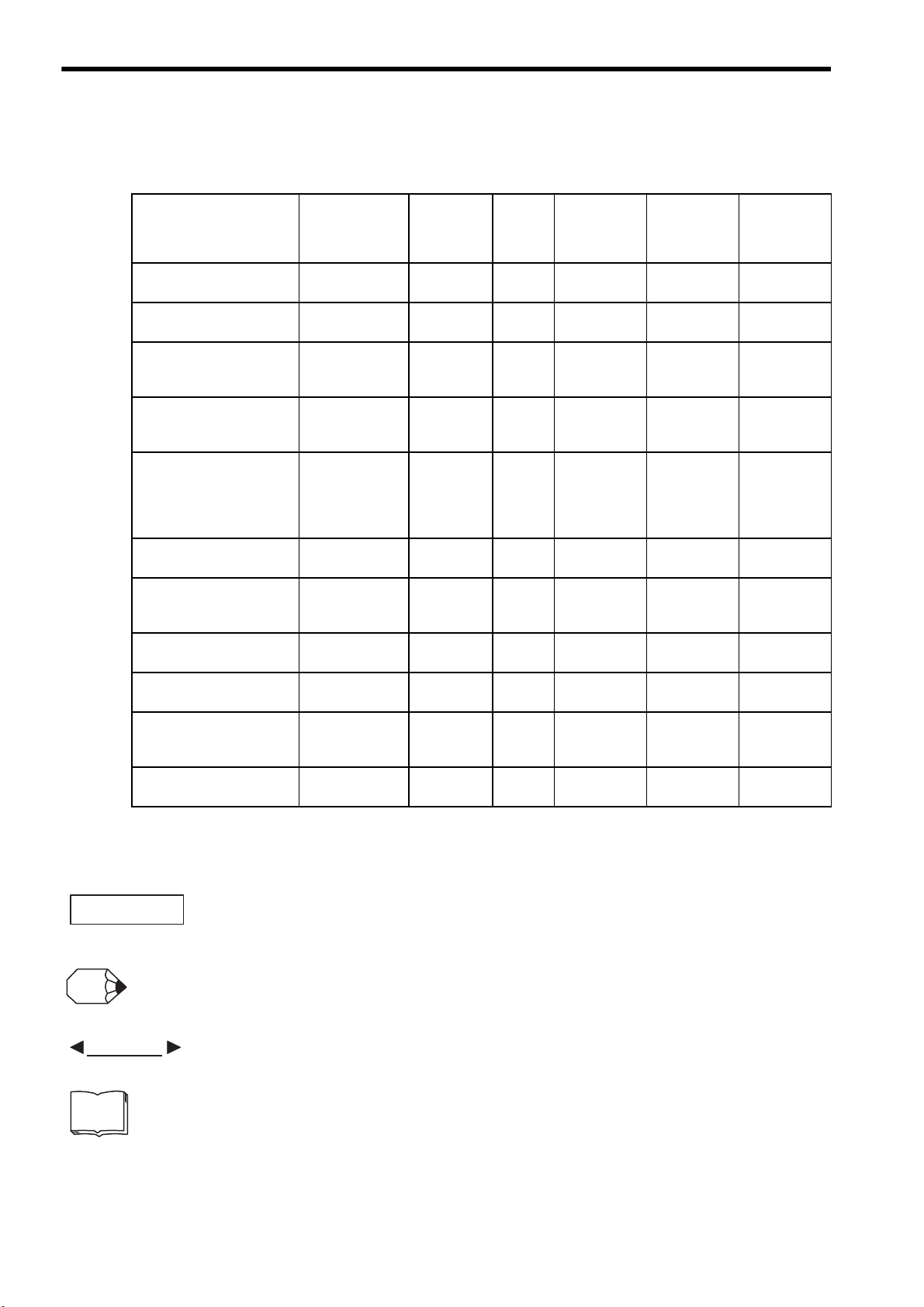
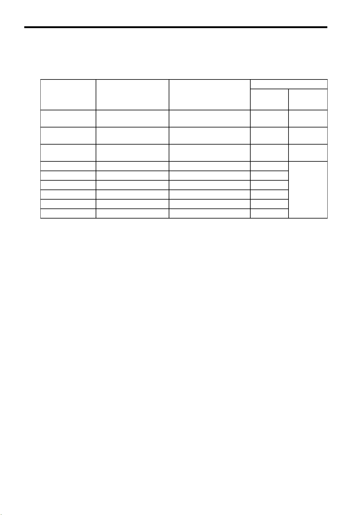
Quick access to your required information
Read the chapters marked with 9 to get the information required for your purpose.
Chapter
Chapter 1
Outline
Chapter 2
Selections
Chapter 3
Servomotor Specifications
and Dimensional Drawings
Chapter 4
SERVOPACK Specifications
and Dimensional Drawings
Chapter 5
Specifications and
Dimensional Drawings of
Cables and Peripheral
Devices
Chapter 6
Wiring
Chapter 7
Digital Operator/Panel
Operator
Chapter 8
Operation
Chapter 9
Adjustments
Chapter 10
Inspection, Maintenance,
and Troubleshooting
Chapter 11
Appendix
SERVOPACKs,
Servomotors,
and Peripheral
Devices
Ratings and
Character-
istics
System
Design
Panel
Configura-tion
and Wiring
Trial Operation
and Servo
Adjustment
Inspection and
Maintenance
9
9
9999
9999
9999
99 9
99
9
9
9
9999
iv
Visual Aids
■
The following aids are used to indicate certain types of information for easier reference.
• Indicates important information that should be memorized, including precautions such as alarm dis-
plays to avoid damaging the devices.
• Indicates supplemental information.
• Indicates application examples.
• Indicates definitions of difficult terms or terms that have not been previously explained in this man-
ual.
Page 5

Indication of Reverse Signals
■
In this manual, the names of reverse signals (ones that are valid when low) are written with a forward slash (/)
before the signal name, as shown in the following example:
• S-ON
=
/S-ON
• P-CON
Related Manuals
■
=
/P-CON
Refer to the following manuals as required.
Manual Name Manual Number Contents
-II Series SGMH/SGDH
Σ
Digital Operator Operation Manual
-II Series SERVOPACKs
Σ
Personal Computer Monitoring Software
Operation Manual
-II Series SGDH
Σ
Fully Closed Interface Unit
User’s Manual
Type: JUSP-FC100
-II Series SGDH MECHATROLINK
Σ
Application Module User’s Manual
Type: JUSP-NS100
-II Series SGDH MECHATROLINK-II
Σ
Application Module User’s Manual
Type: JUSP-NS115
-II Series SGDH
Σ
DeviceNet Application Module
User’s Manual
Type: JUSP-NS300
-II Series SGDH PROFIBUS-DP
Σ
Application Module User’s Manual
Type: JUSP-NS500
TOE-S800-34 Provides detailed information on the operating method
SIE-S800-35 Describes the using and the operating methods on soft-
SIE-C718-5 Provides detailed information on the fully closed con-
SIE-C718-4 Provides detailed information on MECHATROLINK
SIEPC71080001 Provides detailed information on MECHATROLINK-II
SIE-C718-6 Provides detailed information on DeviceNet communi-
SIE-C718-8 Provides detailed information on PROFIBUS-DP
of JUSP-OP02A-2 type Digital Operator (option
device).
ware that changes the local personal computer into the
monitor equipment for the Σ-II Series servomotor.
trol of the JUSP-FC100 interface unit.
communications.
communications.
cations.
communications.
v
Page 6
WARNING
CAUTION
PROHIBITED
MANDATORY
Safety Information
The following conventions are used to indicate precautions in this manual. Failure to heed precautions provided
in this manual can result in serious or possibly even fatal injury or damage to the products or to related equipment
and systems.
Indicates precautions that, if not heeded, could possibly result in loss of life or serious
injury.
Indicates precautions that, if not heeded, could result in relatively serious or minor
injury, damage to the product, or faulty operation.
In some situations, the precautions indicated could have serious consequences if not heeded.
Indicates prohibited actions that must not be performed. For example, this symbol
would be used as follows to indicate that fire is prohibited: .
Indicates compulsory actions that must be performed. For example, this symbol would
be used as follows to indicate that grounding is compulsory: .
vi
Page 7
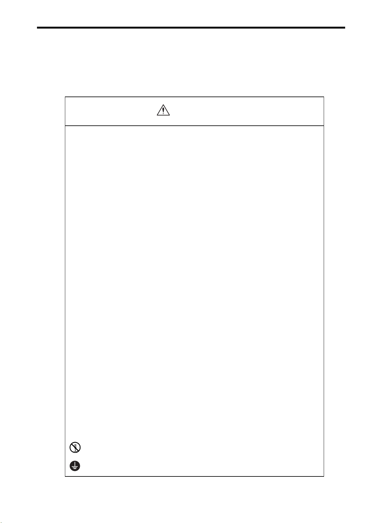
Notes for Safe Operation
WARNING
Read this manual thoroughly before checking products on delivery, storage and transportation, installation,
wiring, operation and inspection, and disposal of the AC servo drive.
• Never touch any rotating motor parts while the motor is running.
Failure to observe this warning may result in injury.
• Before starting operation with a machine connected, make sure that an emergency stop can
be applied at any time.
Failure to observe this warning may result in injury.
• Never touch the inside of the SERVOPACKs.
Failure to observe this warning may result in electric shock.
• Do not touch terminals for five minutes after the power is turned OFF.
Residual voltage may cause electric shock.
• Do not touch terminals for five minutes after voltage resistance test.
Residual voltage may cause electric shock.
• Follow the procedures and instructions for trial operation precisely as described in this
manual.
Malfunctions that occur after the servomotor is connected to the equipment not only damage the
equipment, but may also cause an accident resulting in death or injury.
• The multiturn limit value must be changed only for special applications.
Changing it inappropriately or unintentionally can be dangerous.
• If the Multiturn Limit Disagreement alarm (A.CC) occurs, check the setting of parameter
Pn205 in the SERVOPACK to be sure that it is correct.
If Fn013 is executed when an incorrect value is set in Pn205, an incorrect value will be set in the
encoder. The alarm will disappear even if an incorrect value is set, but incorrect positions will be
detected, resulting in a dangerous situation where the machine will move to unexpected positions.
• Do not remove the front cover, cables, connectors, or optional items while the power is ON.
Failure to observe this warning may result in electric shock.
• Installation, disassembly, or repair must be performed only by authorized personnel.
Failure to observe this warning may result in electric shock or injury.
• Do not damage, press, exert excessive force or place heavy objects on the cables.
Failure to observe this warning may result in electric shock, stopping operation of the product, or
burning.
• Provide an appropriate stopping device on the machine side to ensure safety.
A holding brake for a servomotor with brake is not a stopping device for ensuring safety.
Failure to observe this warning may result in injury.
• Do not come close to the machine immediately after resetting momentary power loss to
avoid an unexpected restart.
Take appropriate measures to ensure safety against an unexpected restart.
Failure to observe this warning may result in injury.
• Do not modify products.
Failure to observe this warning may result in injury or damage to products.
• Connect the ground terminal to electrical codes (ground resistance: 100
Improper grounding may result in electric shock or fire.
or less).
Ω
vii
Page 8
CAUTION
CAUTION
CAUTION
Checking on Delivery
• Always use the servomotor and SERVOPACK in one of the specified combinations.
Failure to observe this caution may result in fire or malfunction.
Storage and Transportation
• Do not store or install the product in the following places.
• Locations subject to direct sunlight.
• Locations subject to temperatures outside the range specified in the storage or installation temperature conditions.
• Locations subject to humidity outside the range specified in the storage or installation humidity conditions.
• Locations subject to condensation as the result of extreme changes in temperature.
• Locations subject to corrosive or flammable gases.
• Locations subject to dust, salts, or iron dust.
• Locations subject to exposure to water, oil, or chemicals.
• Locations subject to shock or vibration.
Failure to observe this caution may result in fire, electric shock, or damage to the product.
• Do not hold the product by the cables or motor shaft while transporting it.
Failure to observe this caution may result in injury or malfunction.
• Do not place any load exceeding the limit specified on the packing box.
Failure to observe this caution may result in injury or malfunction.
• If disinfectants or insecticides must be used to treat packing materials such as wooden frames, pallets, or
plywood, the packing materials must be treated before the product is packaged, and methods other than
fumigation must be used.
Example: Heat treatment, where materials are kiln-dried to a core temperature of 56
minutes or more.
If the electronic products, which include stand-alone products and products installed in machines, are packed with
fumigated wooden materials, the electrical components may be greatly damaged by the gases or fumes resulting from
the fumigation process. In particular, disinfectants containing halogen, which includes chlorine, fluorine, bromine, or
iodine can contribute to the erosion of the capacitors.
Installation
• Never use the products in an environment subject to water, corrosive gases, inflammable gases, or
combustibles.
Failure to observe this caution may result in electric shock or fire.
• Do not step on or place a heavy object on the product.
Failure to observe this caution may result in injury.
• Do not cover the inlet or outlet parts and prevent any foreign objects from entering the product.
Failure to observe this caution may cause internal elements to deteriorate resulting in malfunction or fire.
C for 30
°
viii
• Be sure to install the product in the correct direction.
Failure to observe this caution may result in malfunction.
Page 9
Installation(cont’d
CAUTION
WARNING
Host Controller
Servo OFF
PG
M
Thermal
protector
Main circuit
magnetic
contactors
Main circuit
power supply
SERVOPACK
• Provide the specified clearances between the SERVOPACK and the control panel or with
other devices.
Failure to observe this caution may result in fire or malfunction.
• Do not apply any strong impact.
Failure to observe this caution may result in malfunction.
Wiring
• Connect the ground terminal to electrical codes (ground resistance: 100 Ω or less).
Improper grounding may result in electric shock or fire.
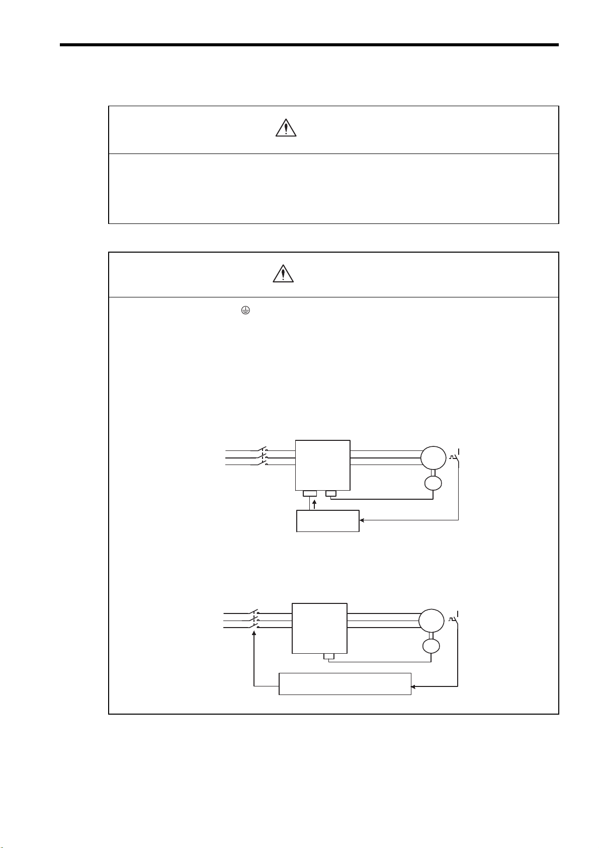
• Use the thermal protector built into the servomotor according to either of the two following methods.
SGMVH servomotors are cooled by a fan. If the fan is defective or power to the fan is disconnected, heat from the
motor may result in burns or fire.
Method 1:
• Wire the output from the thermal protector to the host controller and turn OFF the servo when the thermal
protector operates.
)
Method 2:
• Wire the thermal protector to the operating circuit of the main circuit magnetic contactors or the host
controller and turn OFF the main circuit magnetic contactor when the thermal protector operates.
Main circuit
magnetic
Main circuit
power supply
To main circuit
magnetic contactors
contactors
SERVOPACK
Host controller or operating circuit
of main circuit magnetic contactors
M
PG
Thermal
protector
ix
Page 10

CAUTION
• Do not connect a three-phase power supply to the U, V, or W output terminals.
Failure to observe this caution may result in injury or fire.
• Securely connect the power supply terminals and motor output terminals.
Failure to observe this caution may result in fire.
• Do not bundle or run power and signal lines together in the same duct. Keep power and signal lines
separated by at least 30 cm.
• Use twisted-pair shielded wires or multi-core twisted pair shielded wires for signal and encoder (PG)
feedback lines.
The maximum length is 3 m for reference input lines and is 20 m for PG feedback lines.
• Do not touch the power terminals for five minutes after turning power OFF because high voltage may still
remain in the SERVOPACK.
Make sure the charge indicator is turned OFF first before starting an inspection.
• Avoid frequently turning power ON and OFF.
Since the SERVOPACK has a capacitor in the power supply, a high charging current flows for 0.2 seconds when
power is turned ON. Frequently turning power ON and OFF causes main power devices such as capacitors and fuses
to deteriorate, resulting in unexpected problems.
• Install the battery at either the host controller or the SERVOPACK.
It is dangerous to install batteries at both simultaneously, because that sets up a loop circuit between the batteries.
• Be sure to wire correctly and securely.
Failure to observe this caution may result in motor overrun, injury, or malfunction.
• Always use the specified power supply voltage.
An incorrect voltage may result in burning.
• Take appropriate measures to ensure that the input power supply is supplied within the specified voltage
fluctuation range. Be particularly careful in places where the power supply is unstable.
An incorrect power supply may result in damage to the product.
• Install external breakers or other safety devices against short-circuiting in external wiring.
Failure to observe this caution may result in fire.
• Take appropriate and sufficient countermeasures for each when installing systems in the following
locations.
• Locations subject to static electricity or other forms of noise.
• Locations subject to strong electromagnetic fields and magnetic fields.
• Locations subject to possible exposure to radioactivity.
• Locations close to power supplies including power supply lines.
Failure to observe this caution may result in damage to the product.
• Do not reverse the polarity of the battery when connecting it.
Failure to observe this caution may damage the battery or cause it to explode.
x
Page 11

Operation
CAUTION
• Conduct trial operation on the servomotor alone with the motor shaft disconnected from machine to avoid
any unexpected accidents.
Failure to observe this caution may result in injury.
• Before starting operation with a machine connected, change the settings to match the parameters of the
machine.
Starting operation without matching the proper settings may cause the machine to run out of control or malfunction.
• Forward run prohibited (P-OT) and reverse run prohibited (N-OT) signals are not effective during zero point
search mode using parameter Fn003.
• When using the servomotor for a vertical axis, install the safety devices to prevent workpieces to fall off due
to occurrence of alarm or overtravel. Set the servomotor so that it will stop in the zero clamp state at
occurrence of overtravel.
Failure to observe this caution may cause workpieces to fall off due to overtravel.
• Do not touch the SERVOPACK heatsinks, regenerative resistor, or servomotor while power is ON or soon
after the power is turned OFF.
Failure to observe this caution may result in burns due to high temperatures.
• Do not make any extreme adjustments or setting changes of parameters.
Failure to observe this caution may result in injury due to unstable operation.
• When an alarm occurs, remove the cause, reset the alarm after confirming safety, and then resume
operation.
Failure to observe this caution may result in injury.
• Do not use the servo brake of the servomotor for ordinary braking.
Failure to observe this caution may result in malfunction.
• Do not turn the Servo ON or OFF unless necessary.
Failure to observe this caution may cause internal parts to deteriorate.
xi
Page 12
CAUTION
CAUTION
Maintenance and Inspection
• When replacing the SERVOPACK, transfer the previous SERVOPACK parameters to the new
SERVOPACK before resuming operation.
Failure to observe this caution may result in damage to the product.
• Do not attempt to change wiring while the power is ON.
Failure to observe this caution may result in electric shock or injury.
•
Do not disassemble the servomotor.
Failure to observe this caution may result in electric shock or injury.
Disposal
• When disposing of the products, treat them as ordinary industrial waste.
General Precautions
Note the following to ensure safe application.
• The drawings presented in this manual are sometimes shown without covers or protective guards. Always replace
the cover or protective guard as specified first, and then operate the products in accordance with the manual.
• The drawings presented in this manual are typical examples and may not match the product you received.
• This manual is subject to change due to product improvement, specification modification, and manual
improvement. When this manual is revised, the manual code is updated and the new manual is published as a next
edition.
• If the manual must be ordered due to loss or damage, inform your nearest Yaskawa representative or one of the
offices listed on the back of this manual.
• Yaskawa will not take responsibility for the results of unauthorized modifications of this product. Yaskawa shall
not be liable for any damages or troubles resulting from unauthorized modification.
xii
Page 13

CONTENTS
About this Manual - - - - - - - - - - - - - - - - - - - - - - - - - - - - - - - - - - - - - - - - - - - - - - - - - - - - - - - -iii
Safety Information - - - - - - - - - - - - - - - - - - - - - - - - - - - - - - - - - - - - - - - - - - - - - - - - - - - - - - - vi
Notes for Safe Operation - - - - - - - - - - - - - - - - - - - - - - - - - - - - - - - - - - - - - - - - - - - - - - - - - - vii
1 Outline
1.1 Checking Products - - - - - - - - - - - - - - - - - - - - - - - - - - - - - - - - - - - - - - - - - - - - 1-2
1.1.1 Check Items - - - - - - - - - - - - - - - - - - - - - - - - - - - - - - - - - - - - - - - - - - - - - - - - - - - - - - - - - - 1-2
1.1.2 Servomotors - - - - - - - - - - - - - - - - - - - - - - - - - - - - - - - - - - - - - - - - - - - - - - - - - - - - - - - - - - 1-2
1.1.3 SERVOPACKs - - - - - - - - - - - - - - - - - - - - - - - - - - - - - - - - - - - - - - - - - - - - - - - - - - - - - - - - 1-2
1.2 Examples of Servo System Configurations - - - - - - - - - - - - - - - - - - - - - - - - - - - 1-3
1.2.1 Three-phase, 200 V Series- - - - - - - - - - - - - - - - - - - - - - - - - - - - - - - - - - - - - - - - - - - - - - - - 1-3
1.2.2 Three-phase, 400 V Series- - - - - - - - - - - - - - - - - - - - - - - - - - - - - - - - - - - - - - - - - - - - - - - - 1-4
1.3 Applicable Standards - - - - - - - - - - - - - - - - - - - - - - - - - - - - - - - - - - - - - - - - - - 1-5
1.3.1 North American Safety Standards (UL) - - - - - - - - - - - - - - - - - - - - - - - - - - - - - - - - - - - - - - - 1-5
CE Marking- - - - - - - - - - - - - - - - - - - - - - - - - - - - - - - - - - - - - - - - - - - - - - - - - - - - - - - - - - - 1-5
1.3.2
2 Selections
2.1 Servomotor Model Designations - - - - - - - - - - - - - - - - - - - - - - - - - - - - - - - - - - 2-2
2.2 SERVOPACK Model Designations - - - - - - - - - - - - - - - - - - - - - - - - - - - - - - - - - 2-3
Σ-II Series SERVOPACKs and Applicable Servomotor - - - - - - - - - - - - - - - - - - - 2-4
2.3
2.4 Selecting Cables - - - - - - - - - - - - - - - - - - - - - - - - - - - - - - - - - - - - - - - - - - - - - 2-5
2.4.1 Cables for SGMVH Servomotor - - - - - - - - - - - - - - - - - - - - - - - - - - - - - - - - - - - - - - - - - - - - 2-5
2.5 Selecting Peripheral Devices - - - - - - - - - - - - - - - - - - - - - - - - - - - - - - - - - - - - - 2-6
2.5.1 Special Options- - - - - - - - - - - - - - - - - - - - - - - - - - - - - - - - - - - - - - - - - - - - - - - - - - - - - - - - 2-6
2.5.2 Molded-case Circuit Breaker and Fuse Capacity - - - - - - - - - - - - - - - - - - - - - - - - - - - - - - - - 2-8
2.5.3 Noise Filters, Magnetic Contactors, and Brake Power Supply Units - - - - - - - - - - - - - - - - - - - 2-9
2.5.4 Regenerative Resistor Units - - - - - - - - - - - - - - - - - - - - - - - - - - - - - - - - - - - - - - - - - - - - - - 2-9
2.5.5 Dynamic Brake (DB) Units - - - - - - - - - - - - - - - - - - - - - - - - - - - - - - - - - - - - - - - - - - - - - - - 2-10
2.5.6 Thermal Relays- - - - - - - - - - - - - - - - - - - - - - - - - - - - - - - - - - - - - - - - - - - - - - - - - - - - - - - 2-11
3 Servomotor Specifications and Dimensional Drawings
3.1 Ratings and Specifications of SGMVH (1500 min-1) - - - - - - - - - - - - - - - - - - - - - 3-2
-1
3.2 Ratings and Specifications of SGMVH (800 min
) - - - - - - - - - - - - - - - - - - - - - - 3-6
3.3 Mechanical Specifications of Servomotors - - - - - - - - - - - - - - - - - - - - - - - - - - - 3-9
3.3.1 Precautions on Servomotor Installation - - - - - - - - - - - - - - - - - - - - - - - - - - - - - - - - - - - - - - - 3-9
3.3.2 Allowable Radial and Thrust Loads - - - - - - - - - - - - - - - - - - - - - - - - - - - - - - - - - - - - - - - - - 3-13
3.3.3 Mechanical Tolerance - - - - - - - - - - - - - - - - - - - - - - - - - - - - - - - - - - - - - - - - - - - - - - - - - - 3-14
3.3.4 Direction of Servomotor Rotation - - - - - - - - - - - - - - - - - - - - - - - - - - - - - - - - - - - - - - - - - - 3-14
3.3.5 Impact Resistance- - - - - - - - - - - - - - - - - - - - - - - - - - - - - - - - - - - - - - - - - - - - - - - - - - - - - 3-14
3.3.6 Vibration Resistance - - - - - - - - - - - - - - - - - - - - - - - - - - - - - - - - - - - - - - - - - - - - - - - - - - - 3-14
xiii
Page 14

3.3.7 Vibration Class - - - - - - - - - - - - - - - - - - - - - - - - - - - - - - - - - - - - - - - - - - - - - - - - - - - - - - - - 3-15
3.4 Dimensional Drawings of SGMVH Servomotors (1500 min-1) - - - - - - - - - - - - - 3-16
3.5 Dimensional Drawings of SGMVH Servomotors (800 min
-1
) - - - - - - - - - - - - - - 3-22
4 SERVOPACK Specifications and Dimensional Drawings
4.1 SERVOPACK Ratings and Specifications - - - - - - - - - - - - - - - - - - - - - - - - - - - - 4-2
4.1.1 Three-phase 200 V - - - - - - - - - - - - - - - - - - - - - - - - - - - - - - - - - - - - - - - - - - - - - - - - - - - - - -4-2
4.1.2 Three-phase 400 V - - - - - - - - - - - - - - - - - - - - - - - - - - - - - - - - - - - - - - - - - - - - - - - - - - - - - -4-2
4.1.3 SERVOPACK Ratings and Specific
4.2 SERVOPACK Installation - - - - - - - - - - - - - - - - - - - - - - - - - - - - - - - - - - - - - - - 4-5
4.3 SERVOPACK Internal Block Diagrams - - - - - - - - - - - - - - - - - - - - - - - - - - - - - - 4-7
4.3.1 Three-phase 200 V, 22 kW, 30 kW Models - - - - - - - - - - - - - - - - - - - - - - - - - - - - - - - - - - - - -4-7
4.3.2 Three-phase 200 V, 37 kW Model - - - - - - - - - - - - - - - - - - - - - - - - - - - - - - - - - - - - - - - - - - -4-8
4.3.3 Three-phase
4.3.4 Three-phase
4.3.5 Three-phase
4.3.6 Three-phase 400 V, 90 kW Model - - - - - - - - - - - - - - - - - - - - - - - - - - - - - - - - - - - - - - - - - -4-10
400 V, 22 kW, 30 kW Models - - - - - - - - - - - - - - - - - - - - - - - - - - - - - - - - - - - - -4-9
400 V, 37 kW Model - - - - - - - - - - - - - - - - - - - - - - - - - - - - - - - - - - - - - - - - - - -4-9
400 V, 45 kW, 55 kW Models - - - - - - - - - - - - - - - - - - - - - - - - - - - - - - - - - - - - 4-10
4.4 SERVOPACK’s Power Supply Capacities and Power Losses - - - - - - - - - - - - - 4-11
4.5 SERVOPACK Overload Characteristics and Allowable Load Moment of Inertia 4-12
4.5.1 Overload Characteristics - - - - - - - - - - - - - - - - - - - - - - - - - - - - - - - - - - - - - - - - - - - - - - - - -4-12
4.5.2 Starting and Stopping Time - - - - - - - - - - - - - - - - - - - - - - - - - - - - - - - - - - - - - - - - - - - - - - - 4-13
4.5.3 Load Moment of Inertia - - - - - - - - - - - - - - - - - - - - - - - - - - - - - - - - - - - - - - - - - - - - - - - - - -4-14
ations - - - - - - - - - - - - - - - - - - - - - - - - - - - - - - - - - - - - - -4-3
4.6 SERVOPACK Dimensional Drawings - - - - - - - - - - - - - - - - - - - - - - - - - - - - - - 4-16
4.6.1 Three-phase 200 V, 22 kW, 30 kW Models - - - - - - - - - - - - - - - - - - - - - - - - - - - - - - - - - - - - 4-16
4.6.2 Three-phase 200 V, 37 kW Model - - - - - - - - - - - - - - - - - - - - - - - - - - - - - - - - - - - - - - - - - -4-17
4.6.3 Three-phase 400 V, 22 kW Model - - - - - - - - - - - - - - - - - - - - - - - - - - - - - - - - - - - - - - - - - -4-18
Three-phase 400 V, 30 kW Model - - - - - - - - - - - - - - - - - - - - - - - - - - - - - - - - - - - - - - - - - -4-19
4.6.4
4.6.5 Three-phase 400 V, 37 kW Model - - - - - - - - - - - - - - - - - - - - - - - - - - - - - - - - - - - - - - - - - -4-20
4.6.6 Three-phase 400 V, 45 kW, 55 kW Models - - - - - - - - - - - - - - - - - - - - - - - - - - - - - - - - - - - - 4-20
4.6.7 Three-phase 400 V, 90 kW Model - - - - - - - - - - - - - - - - - - - - - - - - - - - - - - - - - - - - - - - - - -4-21
5 Specifications and Dimensional Drawings of Cables and Peripheral Devices
5.1 SERVOPACK Main Circuit Wire Size - - - - - - - - - - - - - - - - - - - - - - - - - - - - - - - 5-2
5.1.1 Wiring Cables to Main Circuit Terminals - - - - - - - - - - - - - - - - - - - - - - - - - - - - - - - - - - - - - - -5-2
Three-phase 200 V - - - - - - - - - - - - - - - - - - - - - - - - - - - - - - - - - - - - - - - - - - - - - - - - - - - - - -5-3
5.1.2
5.1.3 Three-phase 400 V - - - - - - - - - - - - - - - - - - - - - - - - - - - - - - - - - - - - - - - - - - - - - - - - - - - - - -5-4
5.2 Encoder Cables for CN2 Connector - - - - - - - - - - - - - - - - - - - - - - - - - - - - - - - - 5-6
5.2.1 Encoder Cable with Connectors on Both Ends - - - - - - - - - - - - - - - - - - - - - - - - - - - - - - - - - -5-6
5.2.2 Cable with Loose Wire at Encoder End- - - - - - - - - - - - - - - - - - - - - - - - - - - - - - - - - - - - - - - -5-7
5.3 Connectors and Cables for Encoder Signals - - - - - - - - - - - - - - - - - - - - - - - - - - 5-8
xiv
Page 15

5.4 I/O Signal Cables for CN1 Connector - - - - - - - - - - - - - - - - - - - - - - - - - - - - - - 5-10
5.4.1 Standard Cables - - - - - - - - - - - - - - - - - - - - - - - - - - - - - - - - - - - - - - - - - - - - - - - - - - - - - - 5-10
5.4.2 Connector Type and Cable Size - - - - - - - - - - - - - - - - - - - - - - - - - - - - - - - - - - - - - - - - - - - 5-10
5.4.3 Connection Diagram - - - - - - - - - - - - - - - - - - - - - - - - - - - - - - - - - - - - - - - - - - - - - - - - - - - 5-12
5.5 Peripheral Devices - - - - - - - - - - - - - - - - - - - - - - - - - - - - - - - - - - - - - - - - - - - 5-13
5.5.1 Cables for Connecting Personal Computers- - - - - - - - - - - - - - - - - - - - - - - - - - - - - - - - - - - 5-13
5.5.2 Digital Operator- - - - - - - - - - - - - - - - - - - - - - - - - - - - - - - - - - - - - - - - - - - - - - - - - - - - - - - 5-14
5.5.3 Cables for Analog Monitor - - - - - - - - - - - - - - - - - - - - - - - - - - - - - - - - - - - - - - - - - - - - - - - 5-15
5.5.4 Connector Terminal Block Converter Unit - - - - - - - - - - - - - - - - - - - - - - - - - - - - - - - - - - - - 5-16
5.5.5 Brake Power Supply Unit - - - - - - - - - - - - - - - - - - - - - - - - - - - - - - - - - - - - - - - - - - - - - - - - 5-17
5.5.6 Absolute Encoder Battery- - - - - - - - - - - - - - - - - - - - - - - - - - - - - - - - - - - - - - - - - - - - - - - - 5-18
5.5.7 Molded-case Circuit Breaker (MCCB) - - - - - - - - - - - - - - - - - - - - - - - - - - - - - - - - - - - - - - - 5-19
5.5.8 Noise Filter - - - - - - - - - - - - - - - - - - - - - - - - - - - - - - - - - - - - - - - - - - - - - - - - - - - - - - - - - - 5-20
5.5.9 Surge Absorber- - - - - - - - - - - - - - - - - - - - - - - - - - - - - - - - - - - - - - - - - - - - - - - - - - - - - - - 5-22
5.5.10 Regenerative Resistor Unit- - - - - - - - - - - - - - - - - - - - - - - - - - - - - - - - - - - - - - - - - - - - - - 5-23
5.5.11 Dynamic Brake (DB) Unit - - - - - - - - - - - - - - - - - - - - - - - - - - - - - - - - - - - - - - - - - - - - - - - 5-29
5.5.12 Thermal Relays - - - - - - - - - - - - - - - - - - - - - - - - - - - - - - - - - - - - - - - - - - - - - - - - - - - - - - 5-36
5.5.13 Variable Resistor for Speed and Torque Setting - - - - - - - - - - - - - - - - - - - - - - - - - - - - - - - 5-39
5.5.14 Encoder Signal Converter Unit - - - - - - - - - - - - - - - - - - - - - - - - - - - - - - - - - - - - - - - - - - - 5-40
5.5.15 MECHATROLINK Application Module - - - - - - - - - - - - - - - - - - - - - - - - - - - - - - - - - - - - - - 5-41
5.5.16 DeviceNet Application Module - - - - - - - - - - - - - - - - - - - - - - - - - - - - - - - - - - - - - - - - - - - 5-42
5.5.17 PROFIBUS-DP Application Module - - - - - - - - - - - - - - - - - - - - - - - - - - - - - - - - - - - - - - - - 5-43
5.5.18 Fully-closed Application Module - - - - - - - - - - - - - - - - - - - - - - - - - - - - - - - - - - - - - - - - - - 5-44
6 Wiring
6.1 Wiring Main Circuit - - - - - - - - - - - - - - - - - - - - - - - - - - - - - - - - - - - - - - - - - - - - 6-2
6.1.1 Names and Functions of M
6.1.2 Typical Main Circuit Wiring Examples - - - - - - - - - - - - - - - - - - - - - - - - - - - - - - - - - - - - - - - - 6-4
6.2 Wiring Encoders - - - - - - - - - - - - - - - - - - - - - - - - - - - - - - - - - - - - - - - - - - - - - - 6-8
6.2.1 Connecting an Encoder (CN2) and Output Signals from the SERVOPACK (CN1) - - - - - - - - - 6-8
6.2.2 Encoder Connector (CN2) Terminal Layout - - - - - - - - - - - - - - - - - - - - - - - - - - - - - - - - - - - - 6-9
6.3 I/O Signal Connections - - - - - - - - - - - - - - - - - - - - - - - - - - - - - - - - - - - - - - - - 6-10
6.3.1 Example of I/O Signal Connection- - - - - - - - - - - - - - - - - - - - - - - - - - - - - - - - - - - - - - - - - - 6-10
6.3.2 I/O Signal Connector (CN1) Terminal Layout - - - - - - - - - - - - - - - - - - - - - - - - - - - - - - - - - - 6-11
6.3.3 I/O Signal (CN1) Names and Functions - - - - - - - - - - - - - - - - - - - - - - - - - - - - - - - - - - - - - - 6-12
6.3.4 Interface Circuit- - - - - - - - - - - - - - - - - - - - - - - - - - - - - - - - - - - - - - - - - - - - - - - - - - - - - - - 6-14
6.4 Others - - - - - - - - - - - - - - - - - - - - - - - - - - - - - - - - - - - - - - - - - - - - - - - - - - - - 6-17
6.4.1 Wiring Precautions - - - - - - - - - - - - - - - - - - - - - - - - - - - - - - - - - - - - - - - - - - - - - - - - - - - - 6-17
6.4.2 Wiring for Noise Control - - - - - - - - - - - - - - - - - - - - - - - - - - - - - - - - - - - - - - - - - - - - - - - - - 6-18
6.4.3 Using More Than One SERVOPACK- - - - - - - - - - - - - - - - - - - - - - - - - - - - - - - - - - - - - - - - 6-22
6.4.4 Extending Encoder Cables - - - - - - - - - - - - - - - - - - - - - - - - - - - - - - - - - - - - - - - - - - - - - - - 6-24
ain Circuit Terminals - - - - - - - - - - - - - - - - - - - - - - - - - - - - - - - - - 6-2
xv
Page 16

7 Digital Operator/Panel Operator
7.1 Functions on Digital Operator/Panel Operator - - - - - - - - - - - - - - - - - - - - - - - - - 7-2
7.1.1 Connecting the Digital Operator - - - - - - - - - - - - - - - - - - - - - - - - - - - - - - - - - - - - - - - - - - - - -7-2
7.1.2 Key Names and Functions - - - - - - - - - - - - - - - - - - - - - - - - - - - - - - - - - - - - - - - - - - - - - - - -7-3
7.1.3 Basic Mode Selection and Operation - - - - - - - - - - - - - - - - - - - - - - - - - - - - - - - - - - - - - - - - -7-4
7.1.4 Status Display - - - - - - - - - - - - - - - - - - - - - - - - - - - - - - - - - - - - - - - - - - - - - - - - - - - - - - - - -7-5
7.2 Operation in Utility Function Mode (Fn) - - - - - - - - - - - - - - - - - - - - - - - - - 7-7
7.2.1 List of Utility Function Modes - - - - - - - - - - - - - - - - - - - - - - - - - - - - - - - - - - - - - - - - - - - - - - -7-7
7.2.2 Alarm Traceback Data Display (Fn000)- - - - - - - - - - - - - - - - - - - - - - - - - - - - - - - - - - - - - - - -7-8
7.2.3 Zero-point Search Mode (Fn003) - - - - - - - - - - - - - - - - - - - - - - - - - - - - - - - - - - - - - - - - - - - -7-9
7.2.4 Parameter Settings Initialization (Fn005)- - - - - - - - - - - - - - - - - - - - - - - - - - - - - - - - - - - - - - 7-10
7.2.5 Alarm Traceback Data Clear (Fn006) - - - - - - - - - - - - - - - - - - - - - - - - - - - - - - - - - - - - - - - - 7-11
7.2.6 Manual Zero Adjustment and Gain Adjustment of Analog Monitor Output (Fn00C, Fn00D) - -7-12
7.2.7 Offset Adjustment of Motor Current Detection Signal (Fn00E, Fn00F) - - - - - - - - - - - - - - - - -7-15
7.2.8 Password Setting (Protects Parameters from Being Changed) (Fn010) - - - - - - - - - - - - - - - -7-17
7.2.9 Motor Models Display (Fn011) - - - - - - - - - - - - - - - - - - - - - - - - - - - - - - - - - - - - - - - - - - - - - 7-18
7.2.10 Software Version Display (Fn012) - - - - - - - - - - - - - - - - - - - - - - - - - - - - - - - - - - - - - - - - -7-19
7.2.11 Application Module Detection Results Clear (Fn014) - - - - - - - - - - - - - - - - - - - - - - - - - - - -7-20
7.3 Operation in Parameter Setting Mode (Pn)- - - - - - - - - - - - - - - - - - - - - - 7-21
7.3.1 Setting Parameters - - - - - - - - - - - - - - - - - - - - - - - - - - - - - - - - - - - - - - - - - - - - - - - - - - - - - 7-21
7.3.2 Input Circuit Signal Allocation - - - - - - - - - - - - - - - - - - - - - - - - - - - - - - - - - - - - - - - - - - - - -7-24
7.3.3 Output Circuit Signal Allocation - - - - - - - - - - - - - - - - - - - - - - - - - - - - - - - - - - - - - - - - - - - - 7-27
7.4 Operation in Monitor Mode (Un) - - - - - - - - - - - - - - - - - - - - - - - - - - - - - 7-29
7.4.1 List of Monitor Modes - - - - - - - - - - - - - - - - - - - - - - - - - - - - - - - - - - - - - - - - - - - - - - - - - - - 7-29
8 Operation
8.1 Trial Operation - - - - - - - - - - - - - - - - - - - - - - - - - - - - - - - - - - - - - - - - - - - - - - - 8-4
Trial Operation for Servomotor without Load - - - - - - - - - - - - - - - - - - - - - - - - - - - - - - - - - - - -8-6
8.1.1
8.1.2 Trial Operation for Servomotor without Load from Host Reference - - - - - - - - - - - - - - - - - - - -8-9
Trial Operation with the Servomotor Connected to the Machine
8.1.3
8.1.4 Servomotor with Brakes - - - - - - - - - - - - - - - - - - - - - - - - - - - - - - - - - - - - - - - - - - - - - - - - - 8-16
8.1.5 Position Control by Host Controller - - - - - - - - - - - - - - - - - - - - - - - - - - - - - - - - - - - - - - - - - -8-16
8.2 Control Mode Selection- - - - - - - - - - - - - - - - - - - - - - - - - - - - - - - - - - - - - - - - 8-17
8.3 Setting Common Basic Functions - - - - - - - - - - - - - - - - - - - - - - - - - - - - - - - - 8-18
8.3.1 Setting the Servo ON Signal - - - - - - - - - - - - - - - - - - - - - - - - - - - - - - - - - - - - - - - - - - - - - - 8-18
8.3.2 Switching the Servomotor Rotation Direction- - - - - - - - - - - - - - - - - - - - - - - - - - - - - - - - - - -8-19
8.3.3 Setting the Overtravel Limit Function - - - - - - - - - - - - - - - - - - - - - - - - - - - - - - - - - - - - - - - - 8-20
8.3.4 Setting for Holding Brakes - - - - - - - - - - - - - - - - - - - - - - - - - - - - - - - - - - - - - - - - - - - - - - - -8-22
8.3.5 Selecting the Stopping Method After Servo OFF - - - - - - - - - - - - - - - - - - - - - - - - - - - - - - - -8-26
8.3.6 Instantaneous Power Loss Settings - - - - - - - - - - - - - - - - - - - - - - - - - - - - - - - - - - - - - - - - - 8-27
- - - - - - - - - - - - - - - - - - - - -8-15
xvi
8.4 Absolute Encoders - - - - - - - - - - - - - - - - - - - - - - - - - - - - - - - - - - - - - - - - - - - 8-28
8.4.1 Interface Circuits - - - - - - - - - - - - - - - - - - - - - - - - - - - - - - - - - - - - - - - - - - - - - - - - - - - - - -8-29
8.4.2 Selecting an Absolute Encoder - - - - - - - - - - - - - - - - - - - - - - - - - - - - - - - - - - - - - - - - - - - -8-30
8.4.3 Handling Batteries - - - - - - - - - - - - - - - - - - - - - - - - - - - - - - - - - - - - - - - - - - - - - - - - - - - - - 8-30
Page 17

8.4.4 Replacing Batteries - - - - - - - - - - - - - - - - - - - - - - - - - - - - - - - - - - - - - - - - - - - - - - - - - - - - 8-31
8.4.5 Absolute Encoder Setup (Fn008) - - - - - - - - - - - - - - - - - - - - - - - - - - - - - - - - - - - - - - - - - - 8-32
8.4.6 Absolute Encoder Reception Sequence- - - - - - - - - - - - - - - - - - - - - - - - - - - - - - - - - - - - - - 8-33
8.4.7 Multiturn Limit Setting - - - - - - - - - - - - - - - - - - - - - - - - - - - - - - - - - - - - - - - - - - - - - - - - - - 8-36
8.4.8 Multiturn Limit Setting When Multiturn Limit Disagreement (A.CC) Occurred - - - - - - - - - - - - 8-37
8.5 Operating Using Speed Control with Analog Reference - - - - - - - - - - - - - - - - - 8-38
8.5.1 Setting Parameters - - - - - - - - - - - - - - - - - - - - - - - - - - - - - - - - - - - - - - - - - - - - - - - - - - - - 8-38
8.5.2 Setting Input Signals - - - - - - - - - - - - - - - - - - - - - - - - - - - - - - - - - - - - - - - - - - - - - - - - - - - 8-39
8.5.3 Adjusting Offset- - - - - - - - - - - - - - - - - - - - - - - - - - - - - - - - - - - - - - - - - - - - - - - - - - - - - - - 8-40
8.5.4 Soft Start - - - - - - - - - - - - - - - - - - - - - - - - - - - - - - - - - - - - - - - - - - - - - - - - - - - - - - - - - - - 8-43
8.5.5 Speed Reference Filter - - - - - - - - - - - - - - - - - - - - - - - - - - - - - - - - - - - - - - - - - - - - - - - - - 8-43
8.5.6 Using the Zero Clamp Function - - - - - - - - - - - - - - - - - - - - - - - - - - - - - - - - - - - - - - - - - - - 8-43
8.5.7 Encoder Signal Output - - - - - - - - - - - - - - - - - - - - - - - - - - - - - - - - - - - - - - - - - - - - - - - - - - 8-45
8.5.8 Speed Coincidence Output- - - - - - - - - - - - - - - - - - - - - - - - - - - - - - - - - - - - - - - - - - - - - - - 8-48
8.6 Operating Using Position Control - - - - - - - - - - - - - - - - - - - - - - - - - - - - - - - - - 8-49
8.6.1 Setting Parameters - - - - - - - - - - - - - - - - - - - - - - - - - - - - - - - - - - - - - - - - - - - - - - - - - - - - 8-49
8.6.2 Setting the Electronic Gear- - - - - - - - - - - - - - - - - - - - - - - - - - - - - - - - - - - - - - - - - - - - - - - 8-51
8.6.3 Position Reference - - - - - - - - - - - - - - - - - - - - - - - - - - - - - - - - - - - - - - - - - - - - - - - - - - - - 8-54
8.6.4 Smoothing - - - - - - - - - - - - - - - - - - - - - - - - - - - - - - - - - - - - - - - - - - - - - - - - - - - - - - - - - - 8-57
8.6.5 Positioning Completed Output Signal - - - - - - - - - - - - - - - - - - - - - - - - - - - - - - - - - - - - - - - 8-58
8.6.6 Positioning Near Signal - - - - - - - - - - - - - - - - - - - - - - - - - - - - - - - - - - - - - - - - - - - - - - - - - 8-59
8.6.7 Reference Pulse Inhibit Function (INHIBIT) - - - - - - - - - - - - - - - - - - - - - - - - - - - - - - - - - - - 8-60
8.6.8 Reference Pulse Input Multiplication Switching Function - - - - - - - - - - - - - - - - - - - - - - - - - - 8-61
8.7 Operating Using Torque Control - - - - - - - - - - - - - - - - - - - - - - - - - - - - - - - - - - 8-63
8.7.1 Setting Parameters - - - - - - - - - - - - - - - - - - - - - - - - - - - - - - - - - - - - - - - - - - - - - - - - - - - - 8-63
8.7.2 Torque Reference Input - - - - - - - - - - - - - - - - - - - - - - - - - - - - - - - - - - - - - - - - - - - - - - - - - 8-63
8.7.3 Adjusting the Reference Offset - - - - - - - - - - - - - - - - - - - - - - - - - - - - - - - - - - - - - - - - - - - - 8-64
8.7.4 Limiting Servomotor Speed during Torque Control - - - - - - - - - - - - - - - - - - - - - - - - - - - - - - 8-66
8.8 Operating Using Speed Control with an Internally Set Speed - - - - - - - - - - - - - 8-68
8.8.1 Setting Parameters - - - - - - - - - - - - - - - - - - - - - - - - - - - - - - - - - - - - - - - - - - - - - - - - - - - - 8-68
8.8.2 Input Signal Settings - - - - - - - - - - - - - - - - - - - - - - - - - - - - - - - - - - - - - - - - - - - - - - - - - - - 8-69
8.8.3 Operating Using an Internally Set Speed - - - - - - - - - - - - - - - - - - - - - - - - - - - - - - - - - - - - - 8-69
8.9 Limiting Torque - - - - - - - - - - - - - - - - - - - - - - - - - - - - - - - - - - - - - - - - - - - - - - 8-71
8.9.1 Internal Torque Limit (Limiting Maximum Output Torque) - - - - - - - - - - - - - - - - - - - - - - - - - - 8-71
8.9.2 External Torque Limit (Output Torque Limiting by Input Signals) - - - - - - - - - - - - - - - - - - - - - 8-72
8.9.3 Torque Limiting Using an Analog Voltage Reference- - - - - - - - - - - - - - - - - - - - - - - - - - - - - 8-73
8.9.4 Torque Limiting Using an External Torque Limit and Analog Voltage Reference- - - - - - - - - - 8-74
8.9.5 Checking Output Torque Limiting during Operation - - - - - - - - - - - - - - - - - - - - - - - - - - - - - - 8-75
8.10 Control Mode Selection - - - - - - - - - - - - - - - - - - - - - - - - - - - - - - - - - - - - - - - 8-76
8.10.1 Setting Parameters - - - - - - - - - - - - - - - - - - - - - - - - - - - - - - - - - - - - - - - - - - - - - - - - - - - 8-76
8.10.2 Switching the Control Mode - - - - - - - - - - - - - - - - - - - - - - - - - - - - - - - - - - - - - - - - - - - - - 8-76
xvii
Page 18

8.11 Other Output Signals- - - - - - - - - - - - - - - - - - - - - - - - - - - - - - - - - - - - - - - - - 8-77
8.11.1 Servo Alarm Output (ALM) and Alarm Code Output (ALO1, ALO2, ALO3) - - - - - - - - - - - - - 8-77
8.11.2 Warning Output (/WARN)- - - - - - - - - - - - - - - - - - - - - - - - - - - - - - - - - - - - - - - - - - - - - - - - 8-78
8.11.3 Servomotor running Output Signal (/TGON) - - - - - - - - - - - - - - - - - - - - - - - - - - - - - - - - - - 8-78
8.11.4 Servo Ready (/S-RDY) Output - - - - - - - - - - - - - - - - - - - - - - - - - - - - - - - - - - - - - - - - - - - -8-79
9 Adjustments
9.1 Autotuning - - - - - - - - - - - - - - - - - - - - - - - - - - - - - - - - - - - - - - - - - - - - - - - - - - 9-2
9.1.1 Servo Gain Adjustment Methods - - - - - - - - - - - - - - - - - - - - - - - - - - - - - - - - - - - - - - - - - - - -9-2
9.1.2 List of Servo Adjustment Functions - - - - - - - - - - - - - - - - - - - - - - - - - - - - - - - - - - - - - - - - - -9-2
9.2 Online Autotuning- - - - - - - - - - - - - - - - - - - - - - - - - - - - - - - - - - - - - - - - - - - - - 9-4
9.3 Manual Tuning - - - - - - - - - - - - - - - - - - - - - - - - - - - - - - - - - - - - - - - - - - - - - - - 9-4
9.3.1 Explanation of Servo Gain - - - - - - - - - - - - - - - - - - - - - - - - - - - - - - - - - - - - - - - - - - - - - - - - -9-4
9.3.2 Servo Gain Manual Tuning - - - - - - - - - - - - - - - - - - - - - - - - - - - - - - - - - - - - - - - - - - - - - - - -9-5
9.3.3 Position Loop Gain - - - - - - - - - - - - - - - - - - - - - - - - - - - - - - - - - - - - - - - - - - - - - - - - - - - - - -9-5
9.3.4 Speed Loop Gain - - - - - - - - - - - - - - - - - - - - - - - - - - - - - - - - - - - - - - - - - - - - - - - - - - - - - - -9-6
9.3.5 Speed Loop Integral Time Constant - - - - - - - - - - - - - - - - - - - - - - - - - - - - - - - - - - - - - - - - - -9-6
9.4 Servo Gain Adjustment Functions - - - - - - - - - - - - - - - - - - - - - - - - - - - - - - - - - 9-7
9.4.1 Feed-forward Reference - - - - - - - - - - - - - - - - - - - - - - - - - - - - - - - - - - - - - - - - - - - - - - - - - -9-7
9.4.2 Torque Feed-forward- - - - - - - - - - - - - - - - - - - - - - - - - - - - - - - - - - - - - - - - - - - - - - - - - - - - -9-7
9.4.3 Speed Feed-forward - - - - - - - - - - - - - - - - - - - - - - - - - - - - - - - - - - - - - - - - - - - - - - - - - - - - -9-8
9.4.4 Proportional Control Operation (Proportional Operation Reference)- - - - - - - - - - - - - - - - - - - -9-9
9.4.5 Using the Mode Switch (P/PI Switching) - - - - - - - - - - - - - - - - - - - - - - - - - - - - - - - - - - - - - - 9-10
9.4.6 Setting the Speed Bias - - - - - - - - - - - - - - - - - - - - - - - - - - - - - - - - - - - - - - - - - - - - - - - - - -9-13
9.4.7 Speed Feedback Filter - - - - - - - - - - - - - - - - - - - - - - - - - - - - - - - - - - - - - - - - - - - - - - - - - -9-13
9.4.8 Speed Feedback Compensation - - - - - - - - - - - - - - - - - - - - - - - - - - - - - - - - - - - - - - - - - - -9-13
9.4.9 Switching Gain Settings - - - - - - - - - - - - - - - - - - - - - - - - - - - - - - - - - - - - - - - - - - - - - - - - -9-14
9.4.10 Torque Reference Filter - - - - - - - - - - - - - - - - - - - - - - - - - - - - - - - - - - - - - - - - - - - - - - - - -9-16
9.5 Analog Monitor- - - - - - - - - - - - - - - - - - - - - - - - - - - - - - - - - - - - - - - - - - - - - - 9-20
10 Inspection, Maintenance, and Troubleshooting
10.1 Troubleshooting - - - - - - - - - - - - - - - - - - - - - - - - - - - - - - - - - - - - - - - - - - - - 10-2
10.1.1 Alarm Display Table - - - - - - - - - - - - - - - - - - - - - - - - - - - - - - - - - - - - - - - - - - - - - - - - - - -10-2
10.1.2 Warning Display - - - - - - - - - - - - - - - - - - - - - - - - - - - - - - - - - - - - - - - - - - - - - - - - - - - - - - 10-4
10.1.3 Alarm Display Table when the Application Module is Used - - - - - - - - - - - - - - - - - - - - - - - -10-5
10.1.4 Warning Display Table when the Application Module is Used - - - - - - - - - - - - - - - - - - - - - - 10-6
10.1.5 Troubleshooting of Alarm and Warning - - - - - - - - - - - - - - - - - - - - - - - - - - - - - - - - - - - - - -10-7
10.1.6 Troubleshooting for Malfunction without Alarm Display - - - - - - - - - - - - - - - - - - - - - - - - - - 10-16
xviii
10.2 Inspection and Maintenance - - - - - - - - - - - - - - - - - - - - - - - - - - - - - - - - - - 10-20
10.2.1 Servomotor Inspection - - - - - - - - - - - - - - - - - - - - - - - - - - - - - - - - - - - - - - - - - - - - - - - - 10-20
10.2.2 SERVOPACK Inspection - - - - - - - - - - - - - - - - - - - - - - - - - - - - - - - - - - - - - - - - - - - - - - - 10-20
10.2.3 SERVOPACK’s Parts Replacement Schedule - - - - - - - - - - - - - - - - - - - - - - - - - - - - - - - - 10-21
Page 19

11 Appendix
11.1 Servomotor Capacity Selection Examples - - - - - - - - - - - - - - - - - - - - - - - - - - 11-2
11.1.1 Selection Example for Speed Control- - - - - - - - - - - - - - - - - - - - - - - - - - - - - - - - - - - - - - - 11-2
11.1.2 Selection Example for Position Control - - - - - - - - - - - - - - - - - - - - - - - - - - - - - - - - - - - - - 11-4
11.2 Connection to Host Controller - - - - - - - - - - - - - - - - - - - - - - - - - - - - - - - - - - 11-7
Example of Connection to MP2200/MP2300 Motion Module SVA-01 - - - - - - - - - - - - - - - - 11-7
11.2.1
11.2.2 Example of Connection to MP920 4-axes Analog Module SVA-01 - - - - - - - - - - - - - - - - - - 11-8
11.2.3 Example of Connection to OMRON’s Motion Control Unit - - - - - - - - - - - - - - - - - - - - - - - - 11-9
11.2.4 Example of Connection to OMRON’s Position Control Unit - - - - - - - - - - - - - - - - - - - - - - -11-10
11.2.5 Example of Connection to MITSUBISHI’s AD72 Positioning
Unit (SERVOPACK in Speed Control Mode) - - - - - - - - - - - - - - - - - - - - - - - - - - - - - - - - - -11-11
11.2.6 Example of Connection to MITSUBISHI’s AD75 Positioning Unit
(SERVOPACK in Position Control Mode)- - - - - - - - - - - - - - - - - - - - - - - - - - - - - - - - - - - - -11-12
11.3 List of Parameters- - - - - - - - - - - - - - - - - - - - - - - - - - - - - - - - - - - - - - - - - - 11-13
11.3.1 Utility Functions List - - - - - - - - - - - - - - - - - - - - - - - - - - - - - - - - - - - - - - - - - - - - - - - - - - -11-13
11.3.2 List of Parameters - - - - - - - - - - - - - - - - - - - - - - - - - - - - - - - - - - - - - - - - - - - - - - - - - - - -11-14
11.4 Parameter Recording Table - - - - - - - - - - - - - - - - - - - - - - - - - - - - - - - - - - - 11-29
INDEX
Revision History
xix
Page 20

1
Outline
1
Outline
1.1 Checking Products - - - - - - - - - - - - - - - - - - - - - - - - - - - - - -1-2
1.1.1 Check Items - - - - - - - - - - - - - - - - - - - - - - - - - - - - - - - - - - - - - - - - - 1-2
1.1.2 Servomotors - - - - - - - - - - - - - - - - - - - - - - - - - - - - - - - - - - - - - - - - - 1-2
1.1.3 SERVOPACKs - - - - - - - - - - - - - - - - - - - - - - - - - - - - - - - - - - - - - - - 1-2
1.2 Examples of Servo System Configurations - - - - - - - - - - - - -1-3
1.2.1 Three-phase, 200 V Series - - - - - - - - - - - - - - - - - - - - - - - - - - - - - - - 1-3
1.2.2 Three-phase, 400 V Series - - - - - - - - - - - - - - - - - - - - - - - - - - - - - - - 1-4
1.3 Applicable Standards - - - - - - - - - - - - - - - - - - - - - - - - - - - - - 1-5
1.3.1 North American Safety Standards (UL) - - - - - - - - - - - - - - - - - - - - - - 1-5
CE Marking
1.3.2
- - - - - - - - - - - - - - - - - - - - - - - - - - - - - - - - - - - - - - - - - - 1-5
1-1
Page 21
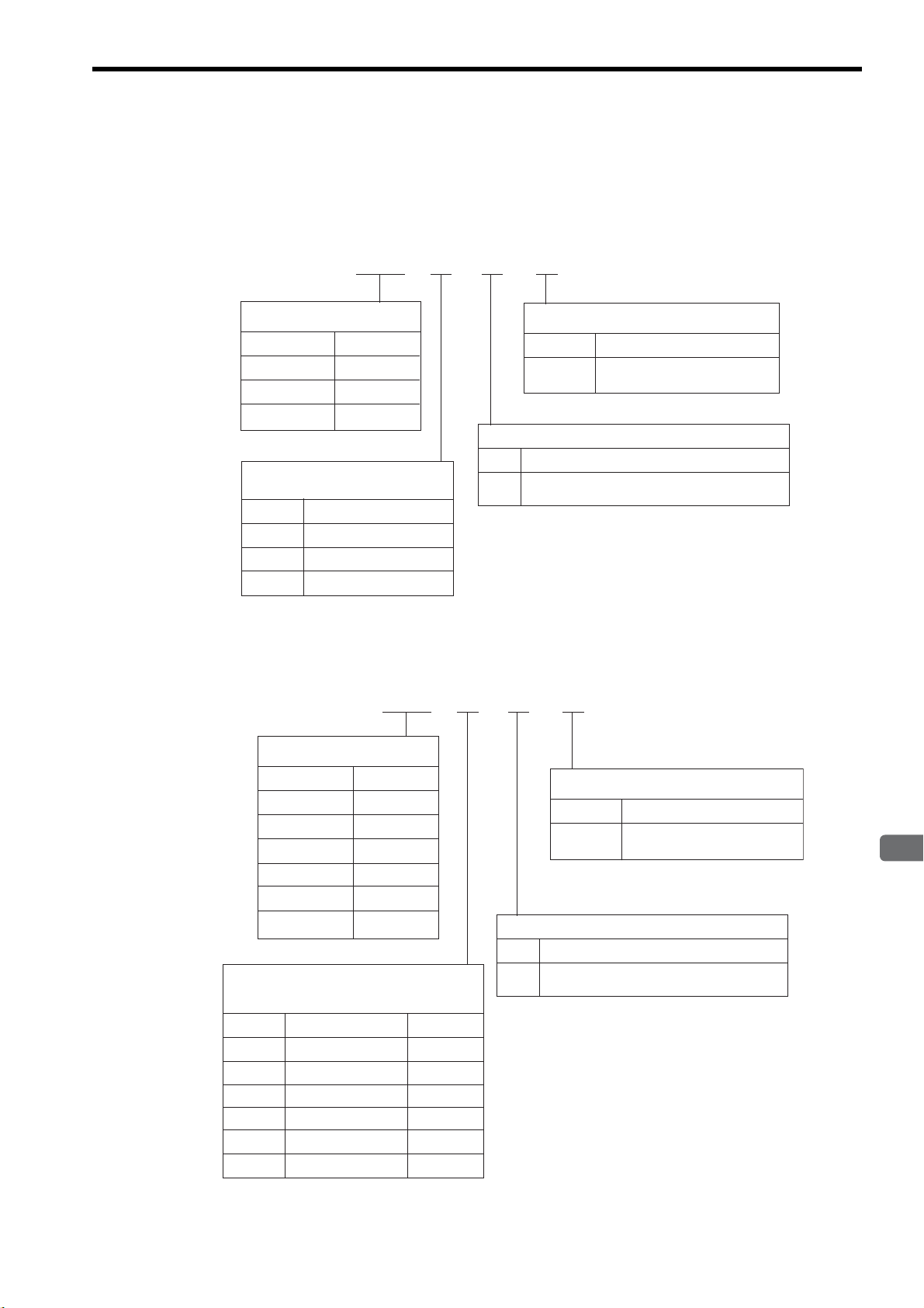
1 Outline
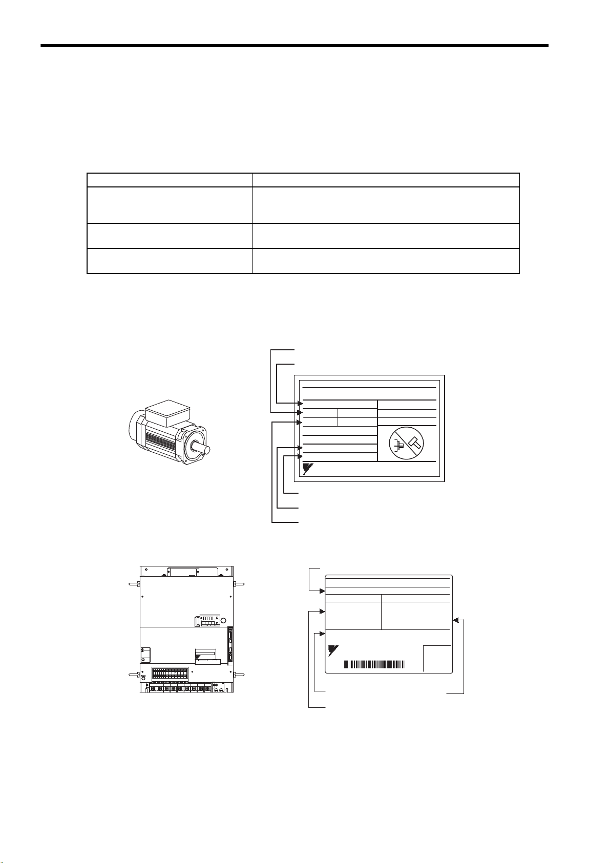
Manufacturing date
Serial number
Servomotor model
Rated output
Rated rotation speed
SGMVH
servomotor
AC SERVO MOTOR
TYPE
SGMVH - 2BDCA
kw N.m
min
SER.NO.
A
RATING
DATE
22
140
1500
58
CONT.
K7A500 101 - 004
9708
ENCODER
UTMAH- B12BDYR11
17 bit
YASKAWA ELECTRIC CORPORATION
JAPAN
-1
Σ-II Series SGDM and SGDH
SERVOPACKs
SERVOPACK model
Serial number
Output power
Applicable power supply
SERVOPACK
SGDH - 3ZDEB
AC-INPUT AC-OUTPUT
MODEL
VOLTS 380- 480
Hz 50/60
PHASE 3
AMPS 145
VOLTS 0 - 480
PHASE 3
AMPS 175
30.0 (40.2)
S / N R7C303 - 221 - 4
YASKAWA ELECTRIC
MADE IN JAPAN
kW (HP)
+2-+1
L1/R L2/S
L3/T
UVW
480 V460
V
DU
400 V 0 V440
V
DWDV B1
380
V
DC
24N
B2
DC
24P
CHARGE
S-HDG
㧖㧖㧖㧖
T DATA/SEEMOD/
KSERVOPAC
AYASKAW
R
O
P
E
R
A
T
O
CN3
8CN
POWER
CN5
WARNING
ෂޓ㒾
ㅢ㔚߮㔚Ḯࠝࡈᓟ5
ಽ㑆ޔ┵ሶㇱߦ⸅ࠆߥ!
electric shock.
Disconnect all power
May cause
ᗵ㔚ߩᕟࠇࠅ
before servicing.
and wait 5 min.
grounding techniques.
ធ⛯ߖࠃ
Use proper
ᔅߕࠕ㧙ࠬ✢ࠍ
1.1.1 Check Items
1.1 Checking Products
The following procedure is used to check the AC servo drives of Σ-ΙΙ Series products on delivery.
1.1.1 Check Items
Check the following items when Σ-ΙΙ Series products are delivered.
Check Items Comments
Are the delivered products the ones
that were ordered?
Does the servomotor shaft rotate
smoothly?
Is there any damage? Check the overall appearance, and check for damage or scratches that
If any of the above items are faulty or incorrect, contact your Yaskawa representative or the dealer from whom
you purchased the products.
1.1.2 Servomotors
Check the model numbers marked on the nameplates on the servomotor and SERVOPACK. (Refer to the descriptions of model numbers in
the following section.)
The servomotor shaft is normal if it can be turned smoothly by hand.
Servomotors with brakes, however, cannot be turned manually.
may have occurred during shipping.
1.1.3 SERVOPACKs
1-2
Page 22
1
Outline
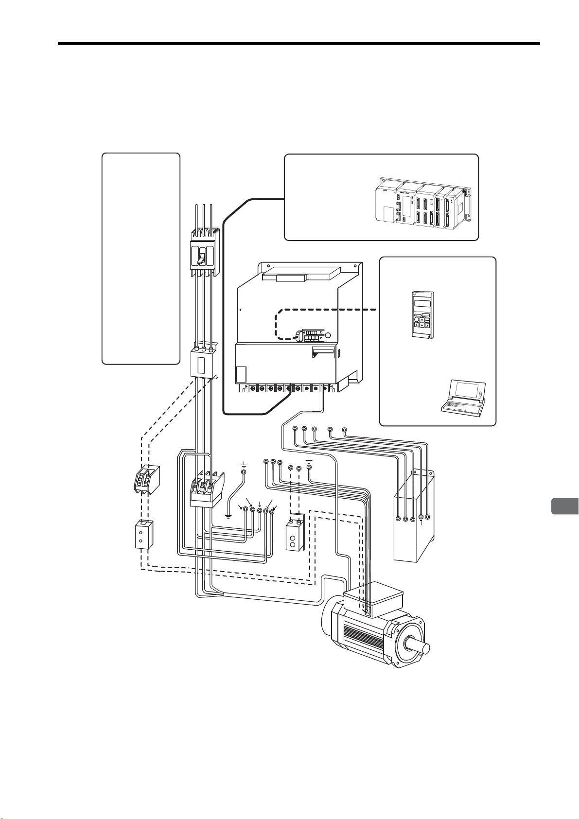
1.2 Examples of Servo System Configurations
U
V
W
B1
B2
RST
CN3
CN1
DB24
DU
DV
DW
DBON
DB24
DU
DV
DW
DBON
Regenerative
Resistor Unit
Power supply for
cooling fan
Power supply
Three-phase 200 VAC
SGMVH
servomotor
SGDM/SGDH SERVOPACK
Host controller
Connect the SGDM/SGDH SERVOPACK
to a Yaskawa or an other manufacturer’s
host controller.
Digital Operator
Allows the user to set parameters or
operation reference and display
operation status or alarm status.
(JUSP-OP02A-2)
Cable model:
Personal computer
Hand-held type
1-meter cable included
Molded-case circuit
breaker (MCCB)
Used to protect power
supply line.
Noise filter
Used to eliminate external noise from power
supply line.
Magnetic contactor *
Turns the servo ON or
OFF.
Brake power supply
Used for SGMVH
servomotor with brake.
LPSE-2H01
(For 200 V input)
Dynamic Brake (DB)
Unit
*
Use a surge absorber
for the magnetic contactor.
Brake power supply
Dynamic Brake Unit
Used if dynamic brake
function is required for the
SERVOPACK.
Note: The Dynamic Brake (DB) Unit DBON and
DB24 terminals can be used with SERVOPACKs of 37 kW or more only.
MP900/MP2000 Series
JZSP-CMS01 to 03
L1/R
L2/S
L3/T
L3C/t
L1C/r
- +1
+2 L1/R L2/S L3/T
UVW
CN2
CN3
CN1
TDATA/SEEMOD/
SERVOPACK
YASK AWA
R
O
P
E
R
A
T
O
CN3
8CN
POWER
CN5
SGDH-
㧖㧖㧖㧖
This section describes examples of basic servo system configuration.
1.2.1 Three-phase, 200 V Series
1.2 Examples of Servo System Configurations
1-3
Page 23
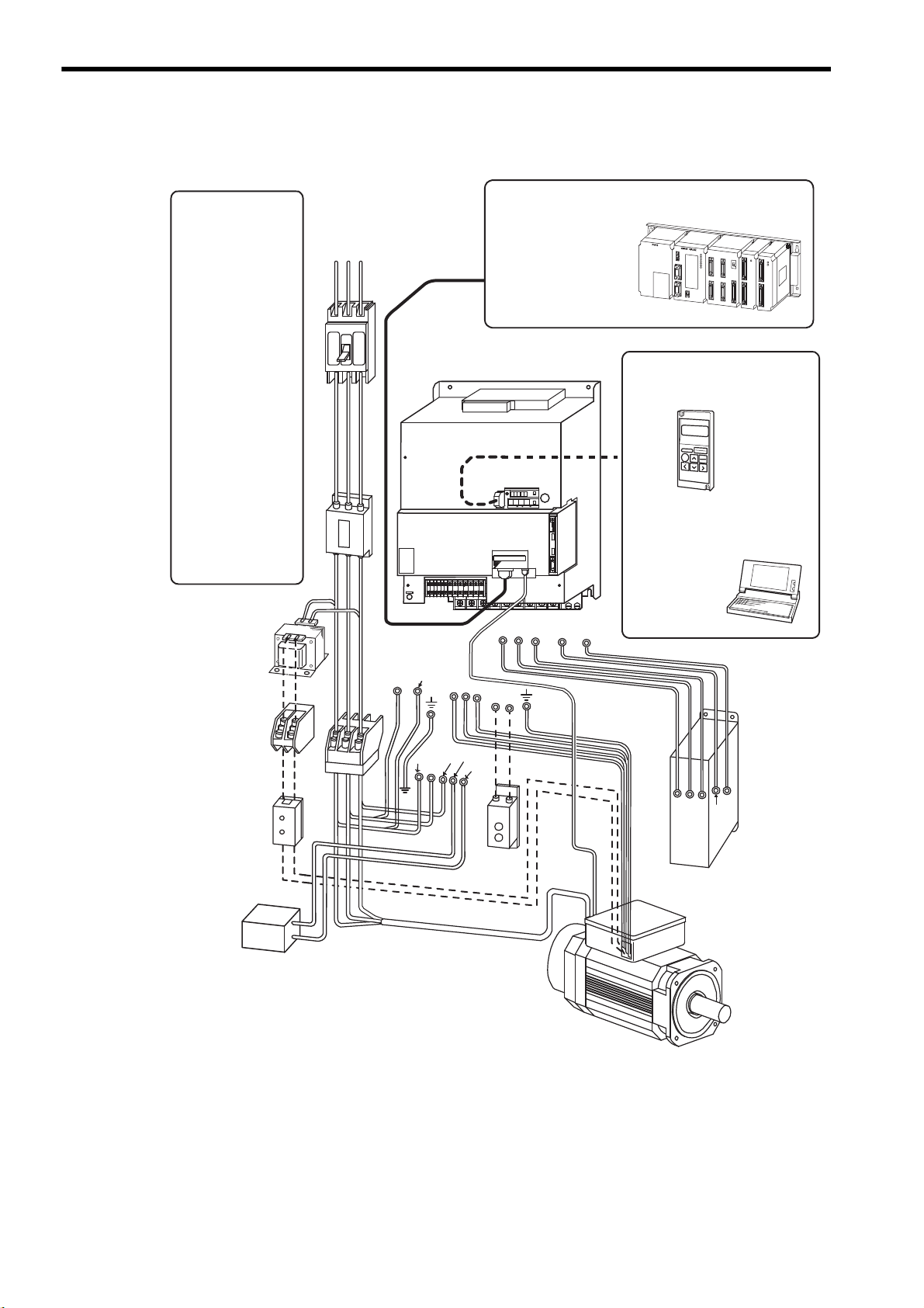
1 Outline
Regenerative
Resistor Unit
U
V
W
B1
B2
0V
Power supply for
cooling fan
Power supply
Three-phase 400 VAC
RST
SGMVH
servomotor
SGDH SERVOPACK
Host controller
Connect the SGDH SERVOPACK to a
Yaskawa or an other manufacturer’s
host controller.
Digital Operator
Allows the user to set parameters or
operation reference and display
operation status or alarm status.
(JUSP-OP02A-2)
Cable model:
Personal computer
Hand-held type
1-meter cable included
Molded-case circuit
breaker (MCCB)
Used to protect power
supply line.
Noise filter
Used to eliminate external noise from power
supply line.
Magnetic contactor *
Turns the servo ON or
OFF.
Brake power supply
Used for SGMVH
servomotor with brake.
LPSE-2H01
(For 200 V input)
Power transformer
Used to switch between
200 V to 400 V.
Dynamic Brake (DB)
Unit
*
Use a surge absorber
for the magnetic contactor.
CN3
CN1
Brake power supply
DB24
DU
DV
DW
DBON
Dynamic Brake Unit
DB24
DU
DV
DW
DBON
Used if dynamic brake
function is required for the
SERVOPACK.
Note: The Dynamic Brake (DB) Unit DBON and
DB24 terminals can be used with SERVOPACKs of 37 kW or more only.
MP900/MP2000 Series
JZSP-CMS01 to 03
380 to 480V
L1/R
L2/S
L3/T
DC24N
DC24P
DC power
supply
(24 VDC)
+
-
CN2
CN3
CN1
8
8
&7
88
8
&9&8 $
8
&%
0
$
&%
2
%*#4)'
5*&)
㧖㧖㧖㧖
6#5''/1&
-5'4812#%
#;#5-#9
4
1
2
'
4
#
6
1
%0
%0
219'4
%0
1.2.2 Three-phase, 400 V Series
1.2.2 Three-phase, 400 V Series
1-4
Page 24
1
Outline
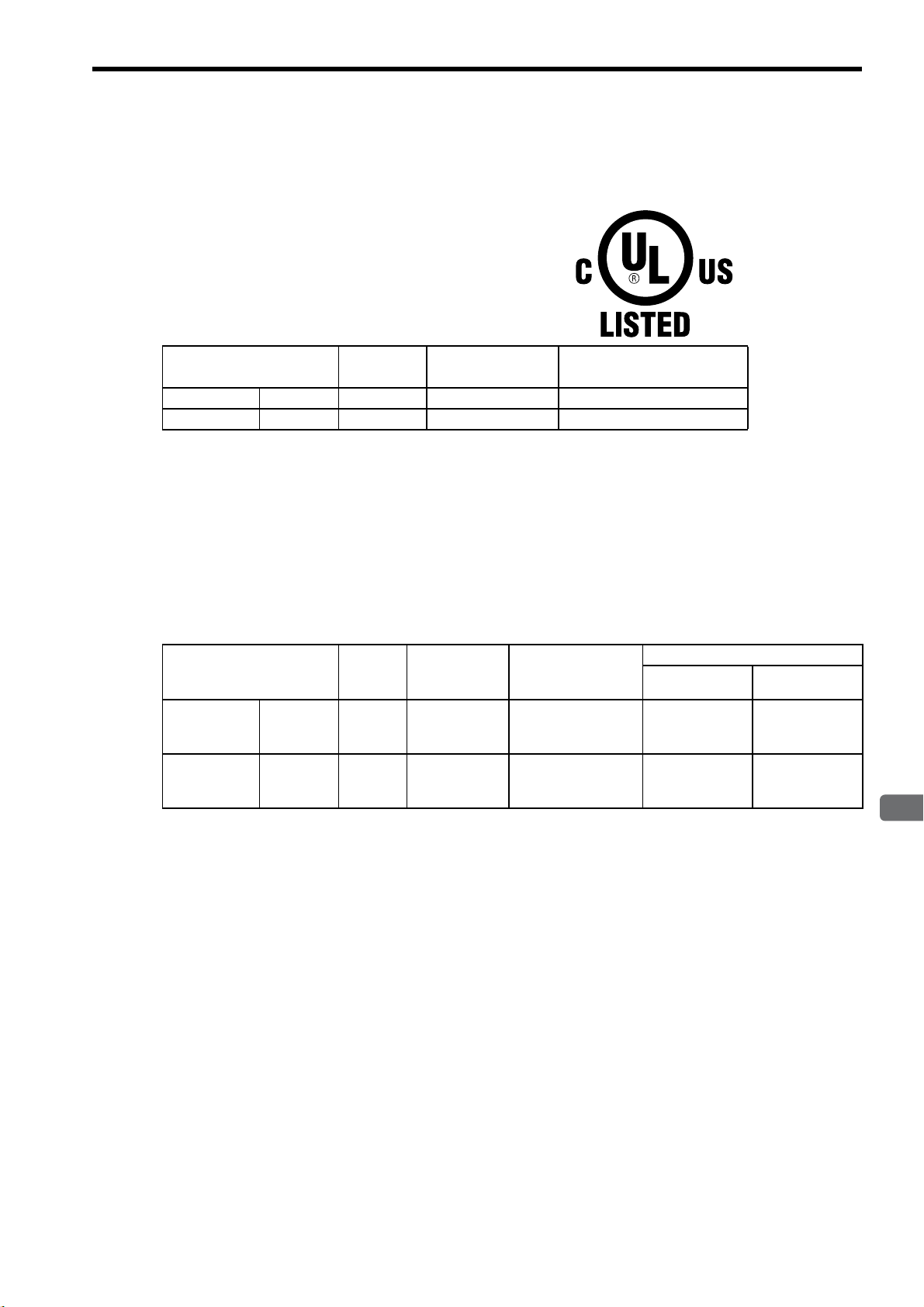
1.3 Applicable Standards
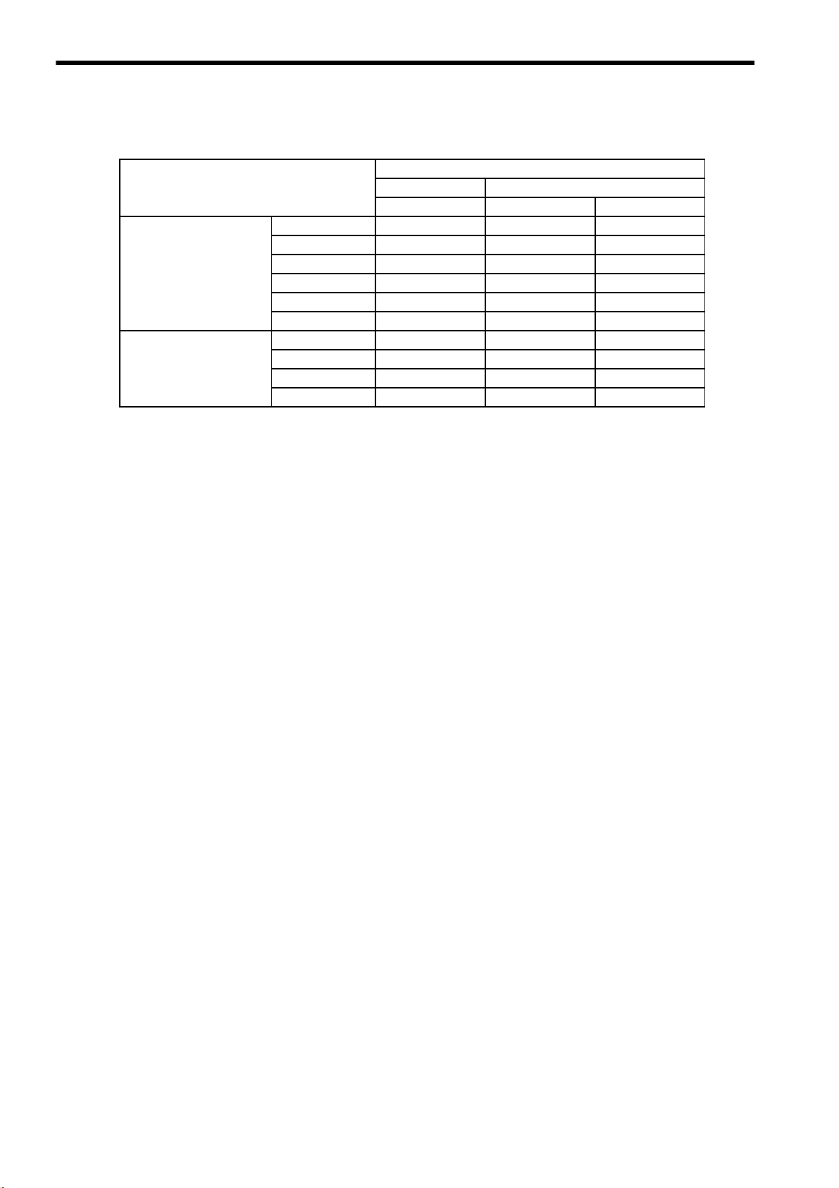
1.3.1 North American Safety Standards (UL)
Model
SERVOPACK SGDH
Servomotor SGMVH
* 1. 200 V SERVOPACKs and servomotors have not obtained certification showing compliance
with UL standards.
* 2. 75 kW SERVOPACKs and servomotors have not obtained certification showing compliance
with UL standards.
* 3. Underwriters Laboratories Inc.
∗1
Voltage
400 V 22 kW to 55 kW UL508C(E147823)
400 V 22 kW to 55 kW UL1004(E165827)
Capacity∗2
∗3
Standards
UL
(UL File No.)
1.3 Applicable Standards
1.3.2 CE Marking
The SGDH SERVOPACK and SGMVH servomotor have not obtained certification showing compliance with CE
marking, but, the following models comply with its standards.
Model
SERVOPACK SGDH
Servomotor SGMVH
* A low voltage directive-compliant model is in development.
Note: Because SERVOPACKs and servomotors are built-in type, reconfirmation is required after
being installed in the final product.
∗
Voltage
400 V 22 kW to 55 kW EN50178
400 V 22 kW to 55 kW
Capacity
∗
Low Voltage
Directive
(compliant)
–
EMC Directive (compliant)
EMI EMS
EN55011
class A group 1
∗
EN55011
class A group 1
EN50082-2
or
EN61000-6-2
EN50082-2
or
EN61000-6-2
1-5
Page 25

2
Selections
2
Selections
2.1 Servomotor Model Designations - - - - - - - - - - - - - - - - - - - - - 2-2
2.2 SERVOPACK Model Designations - - - - - - - - - - - - - - - - - - - 2-3
2.3 Σ-II Series SERVOPACKs and Applicable Servomotor - - - - - 2-4
2.4 Selecting Cables - - - - - - - - - - - - - - - - - - - - - - - - - - - - - - - -2-5
2.4.1 Cables for SGMVH Servomotor - - - - - - - - - - - - - - - - - - - - - - - - - - - 2-5
2.5 Selecting Peripheral Devices - - - - - - - - - - - - - - - - - - - - - - - 2-6
2.5.1 Special Options - - - - - - - - - - - - - - - - - - - - - - - - - - - - - - - - - - - - - - - 2-6
2.5.2 Molded-case Circuit Breaker and Fuse Capacity - - - - - - - - - - - - - - - - 2-8
2.5.3 Noise Filters, Magnetic Contactors, and Brake Power
Supply Units - - - - - - - - - - - - - - - - - - - - - - - - - - - - - - - - - - - - - - - - - 2-9
2.5.4 Regenerative Resistor Units - - - - - - - - - - - - - - - - - - - - - - - - - - - - - - 2-9
2.5.5 Dynamic Brake (DB) Units - - - - - - - - - - - - - - - - - - - - - - - - - - - - - - 2-10
2.5.6 Thermal Relays - - - - - - - - - - - - - - - - - - - - - - - - - - - - - - - - - - - - - - 2-11
2-1
Page 26
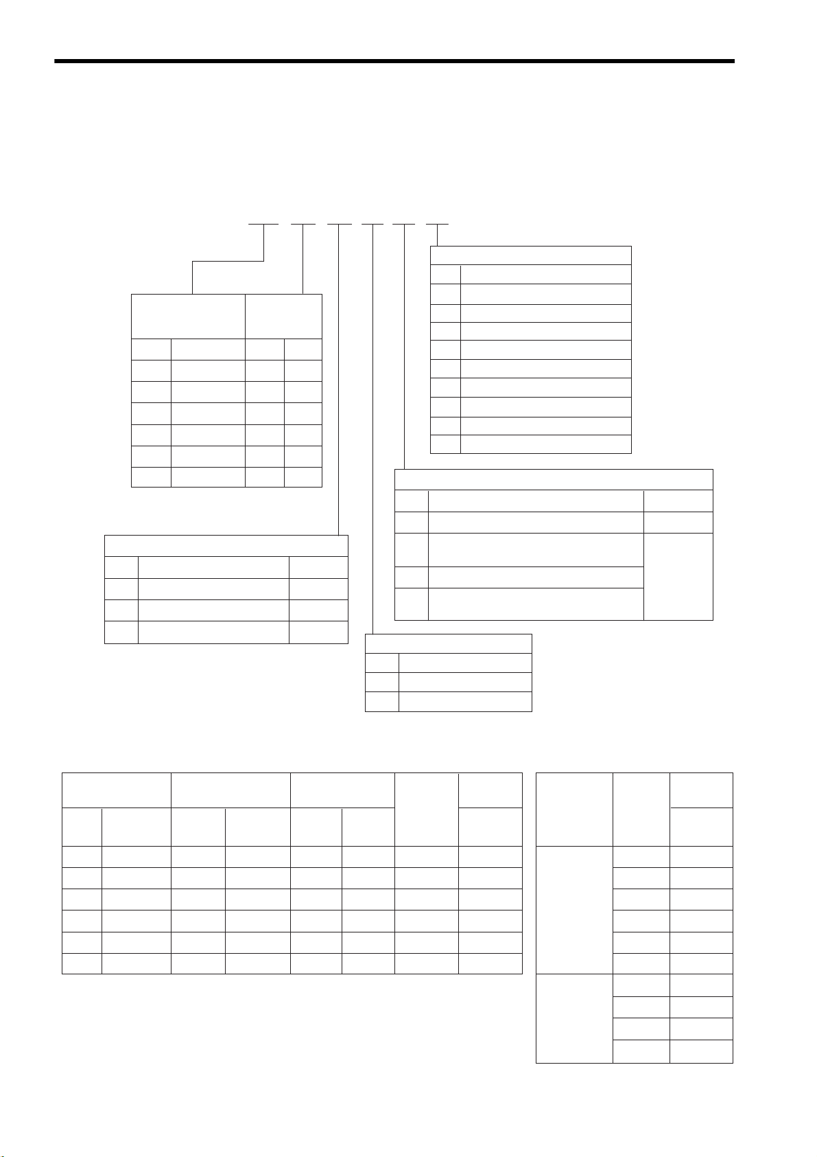
2 Selections
SGMVH − 2B A 2 B 2 N
4th digit: Serial Encoder
7th digit: Brake and Oil Seal
Code
N
1
S
B
C
D
E
F
G
Specifications
Standard (without options)
With dust seal
With oil seal
With 90-VDC brake
With 24-VDC brake
With oil seal and 90-VDC brake
With oil seal and 24-VDC brake
With dust seal and 90-VDC brake
With dust seal and 24-VDC brake
1st + 2nd digits:
Rated Output
(kW)
Code
2B
3Z
3G
4E
5E
7E
Rated Output A
−
−
−
D
3rd digit:
Voltage
A:200V,D:400V
Code
2
3
C
Remarks
Standard
ޓޓSpecifications
17-bit absolute encoder
20-bit absolute encoder
17-bit incremental encoder
: Available
Option
5th digit: Rated Speed
Code
B
D
Specifications
6th digit: Shaft End, Mounting Method
Code
6
RemarksޓޓSpecifications
Flange-mounted, straight without key
Flange-mounted, straight with key
and shaft end tap (
×1)
1st +
2nd
digits
3rd
digit
4th
digit
5th
digit
6th
digit
7th
digit
: Not available
−
1500 min
-1
800 min
-1
Foot-mounted, straight with key
and shaft end tap (
×1)
K
L
Foot-mounted, straight without key
2
Standard
Option
22
30
37
45
55
75
Standard
1st + 2nd digits:
Rated Output (kW)
Code
Rated
Output
BD
5th digit: Rated Speed
B: 1500 min
-1
,
D: 800 min
-1
Flangemounted
Mounting Method
: Available
With
Brake
With
Brake
Rated
Speed
(min
-1
)
Rated
Output
(kW)
With Oil
Seal and
Dust Seal
Foot-
mounted
1500
800
22
30
37
45
55
75
22
30
37
45
Flange-
mounted
22
30
37
45
55
75
2B
3Z
3G
4E
5E
7E
Foot-
mounted
: Not available
−
2.1 Servomotor Model Designations
(1) Available Models
2-2
Page 27
2
Selections
2.2 SERVOPACK Model Designations
Code
2B
3Z
3G
Rated Output
22
30
37
Code
D
Specificatioins
Code
2B
3Z
3G
A
Code
B
Specificatioins
2BSGDM - A D B
5th digit: Applicable Servomotor Model
1st + 2nd digits (kW)
3rd digit: Power Supply
Voltage A: 200 V
4th digit: Model
SGMVH
Servomotor
For torque, speed and position control
1st +
2nd
digits
3rd
digit
4th
digit
5th
digit
: Available
Code
2B
3Z
3G
4E
5E
9Z
Rated Output
22
30
37
45
55
75
D
Δ
Δ
Δ
2BSGDH - A E B
Code
2B
3Z
3G
4E
5E
9Z
A
1st +
2nd
digits
3rd
digit
4th
digit
5th
digit
Code
E
Specificatioins
Code
B
Specificatioins
5th digit: Applicable Servomotor Model
1st + 2nd digits (kW)
3rd digit: Power Supply Voltage
A: 200 V, D: 400 V
4th digit: Model
SGMVH
Servomotor
For torque, speed and position control
: Available
: Option
: Not available
Δ
Select the SERVOPACK according to the applied servomotor.
2.2 SERVOPACK Model Designations
2-3
Page 28
2 Selections
2.3 Σ-II Series SERVOPACKs and Applicable Servomotor
Servomotor
SGMVH-
2B
3Z
1500 min
800 min
Note: =A: 200 V, D: 400 V
Be sure to match the voltage ratio on the servomotor and the SERVOPACK.
-1
-1
3G
4ED
5ED
7ED
2B
3Z
3G
4ED
SGDM- SGDH-
200 V 200 V 400 V
2BADB 2BAEB 2BDEB
3ZADB 3ZAEB 3ZDEB
3GADB 3GAEB 3GDEB
– – 4EDEB
– – 5EDEB
– – 9ZDEB
2BADB 2BAEB 2BDEB
3ZADB 3ZAEB 3ZDEB
3GADB 3GAEB 3GDEB
– – 4EDEB
SERVOPACK
2-4
Page 29
2
Selections
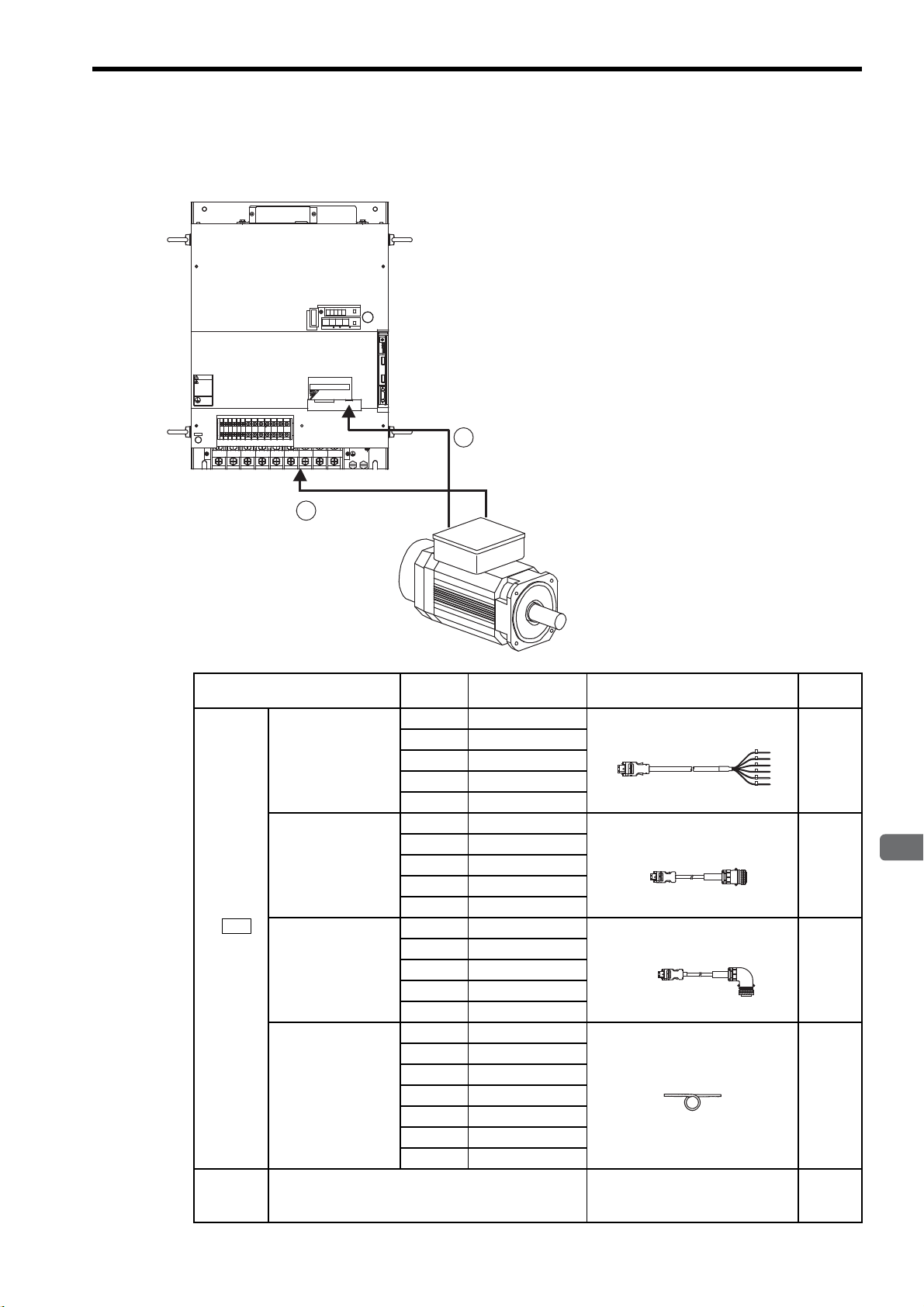
2.4 Selecting Cables
CN2
Encoder
end
SERVOPACK
end
Encoder
end
SERVOPACK
end
2.4.1 Cables for SGMVH Servomotor
219'4
%0
6 & #6#5''/1&
%0
%0
-5'4812#%
5*&)
㧖㧖㧖㧖
#;#5-#9
May cause
electric shock.
Disconnect all power
and wait 5 min.
before servicing.
grounding techniques.
%*#4)'
ෂޓ㒾
WARNING
ᗵ㔚ߩᕟࠇࠅ
ㅢ㔚߮㔚Ḯࠝࡈᓟ5
ಽ㑆ޔ┵ሶㇱߦ⸅ࠆߥ
ᔅߕࠕ㧙ࠬ✢ࠍ
ធ⛯ߖࠃ
Use proper
1
2
'
4
#
6
1
4
&%
8
88
8
8
8
&%
&7
&9&8 $
$
0
2
.4 .5
.6
789
2.4 Selecting Cables
1
c
Encoder
Cable
dMain
Circuit
Cable
2
Name Length Type Specifications
3 m JZSP-CMP23-03
Cable with loose
wire at encoder
end
5 m JZSP-CMP23-05
10 m JZSP-CMP23-10
15 m JZSP-CMP23-15
20 m JZSP-CMP23-20
3 m JZSP-CMP21-03
5 m JZSP-CMP21-05
Cable with a
straight plug
10 m JZSP-CMP21-10
15 m JZSP-CMP21-15
20 m JZSP-CMP21-20
3 m JZSP-CMP22-03
SERVOPACK
end
Cable with an
L-shaped plug
5 m JZSP-CMP22-05
10 m JZSP-CMP22-10
15 m JZSP-CMP22-15
20 m JZSP-CMP22-20
5 m JZSP-CMP29-05
10 m JZSP-CMP29-10
Cables
15 m JZSP-CMP29-15
20 m JZSP-CMP29-20
50 m max.
30 m JZSP-CMP29-30
40 m JZSP-CMP29-40
50 m JZSP-CMP29-50
Cables
Not available.
For details, refer to chapter 5.
Encoder
end
Refer-
ence
5.2.2
5.2.1
5.2.1
5.3
−
2-5
Page 30
2 Selections
Personal
computer
Digital operator
Host controller
I/O signal cable
Connection cable
for digital operator
Connection cable
for personal computer
.4 .5
.6
789
8
8
&7
88
8
&9&8 $
8
&%
0
$
&%
2
%*#4)'
5*&)
㧖㧖㧖㧖
6#5''/1&
-5'4812#%
#;#5-#9
4
1
2
'
4
#
6
1
%0
%0
219'4
%0
WARNING
ෂޓ㒾
ㅢ㔚߮㔚Ḯࠝࡈᓟ5
ಽ㑆ޔ┵ሶㇱߦ⸅ࠆߥ
electric shock.
Disconnect all power
May cause
ᗵ㔚ߩᕟࠇࠅ
before servicing.
and wait 5 min.
grounding techniques.
ធ⛯ߖࠃ
Use proper
ᔅߕࠕ㧙ࠬ✢ࠍ
NS100
S
W
1
S
W
2
A
R
C
N
6
A
C
N
6
B
C
N
4
5
4
0
9
6
1
2
7
8
3
3
5
4
0
9
6
1
2
7
8
NS300
5
4
0
9
6
1
2
7
8
3
X
10
X
1
D
R
C
N
11
M
S
N
S
FC100
MECHATROLINK-I
application
module
(NS100)
DeviceNet
application
module
(NS300)
Fully-closed
application
module
(FC100)
PROFIBUS-DP
application
module
(NS500)
Connector
CN6A
CN11
CN6
CN4
CN11
CN6
CN4CN4
CN6B
CN4
6
NS500
NS115
S
W
1
S
W
2
A
R
C
N
6
A
C
N
6
B
C
N
4
MECHATROLINK-II
application
module
(NS115)
CN6A
CN6B
CN4
CN3
CN8
MODE/SET DATA/
POWER
CN5
.4 .5
.6
789
8
8
&7
88
8
&9&8 $
8
&%
0
$
&%
2
%*#4)'
5*&)
㧖㧖㧖㧖
6#5''/1&
-5'4812#%
#;#5-#9
4
1
2
'
4
#
6
1
%0
%0
219'4
%0
WARNING
ෂޓ㒾
ㅢ㔚߮㔚Ḯࠝࡈᓟ5
ಽ㑆ޔ┵ሶㇱߦ⸅ࠆߥ
electric shock.
Disconnect all power
May cause
ᗵ㔚ߩᕟࠇࠅ
before servicing.
and wait 5 min.
grounding techniques.
ធ⛯ߖࠃ
Use proper
ᔅߕࠕ㧙ࠬ✢ࠍ
Analog monitor cable
Battery for absolute encoder
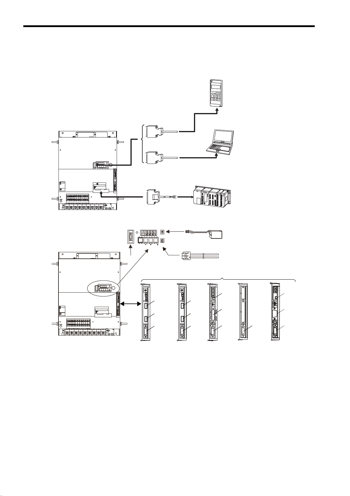
2.5.1 Special Options
2.5 Selecting Peripheral Devices
2.5.1 Special Options
2-6
Page 31

2.5 Selecting Peripheral Devices
2
Selections
CN1
CN3
Operator
end
SERVOPACK
end
CN3
Personal
computer end
SERVOPACK
end
Personal
computer end
SERVOPACK
end
Personal
computer end
SERVOPACK
end
CN5
SERVOPACK end
Monitor end
CN8
Name Length Type Specifications
Connector terminal block
c
converter unit
I/O Signal
Cables
Cable with
loose wires at
one end
d Digital Operator
e
Connection Cable for Digital
Operator
JUSP-TA50PG
1 m JZSP-CKI01-1
2 m JZSP-CKI01-2
3 m JZSP-CKI01-3
JUSP-OP02A-2
1m JZSP-CMS00-1
1.5m JZSP-CMS00-2
2 m JZSP-CMS00-3
Terminal block and 0.5 m connection
cable
Loose wires at host controller end
With connection cable (1 m)
Required only when the digital operator model: JUSP-OP02A-1 for Σ-I
series is used.
D-Sub 25-pin (For PC98)
Refer-
ence
5.5.4
5.4.1
5.5.2
2 m JZSP-CMS01
f
Connection Cable for Personal
Computer
g
Analog Monitor Cable
2 m JZSP-CMS02
2 m JZSP-CMS03
1 m
JZSP-CA01 or
DE9404559
JZSP-BA01-1
h
Battery for Absolute Encoder
Application Module
⑦
∗
* For details, refer to the manuals of each application module.
ER6VC3
JUSP-NS100
JUSP-NS115
JUSP-NS300
JUSP-FC100
JUSP-NS500
D-Sub 9-pin (For DOS/V)
Half-pitch 14-pin (For PC 98)
To connect to a host controller,
3.6 V, 2000 mAh, manufactured by
Toshiba Battery Co., Ltd.
MECHATROLINK-I application
module (NS100)
MECHATROLINK-II application
module (NS115)
DeviceNet application module
(NS300)
Fully-closed application module
(FC100)
PROFIBUS-DP
application module (NS500)
5.5.1
5.5.3
5.5.6
5.5.15
5.5.15
5.5.16
5.5.18
5.5.17
2-7
Page 32
2 Selections
2.5.2 Molded-case Circuit Breaker and Fuse Capacity
2.5.2 Molded-case Circuit Breaker and Fuse Capacity
Select a input fuse or molded-case circuit breaker that comply with UL standard.
SERVOPACK Model
SGDM-2BADB
SGDH-2BAEB
SGDM-3ZADB
SGDH-3ZAEB
SGDM-3GADB
SGDH-3GAEB
SGDH-2BDEB
SGDH-3ZDEB
SGDH-3GDEB
SGDH-4EDEB
SGDH-5EDEB
SGDH-9ZDEB
* 1. Nominal value at the rated load.
* 2. Cutoff characteristics (25
* 3. The values will vary, depending on the 24 VDC control power supply used.
Note: Do not use a fast-acting fuse. Because the SERVOPACK’s power supply is a capacitor
input type, a fast-acting fuse may blow when the power is turned ON.
Power Supply
Capacity per
SERVOPACK
∗1
(kVA)
Current Capacity of the
Molded-case Circuit Breaker
and the Fuse (A)
∗2
Inrush Current (A)
Main Circuit
Power Supply
36.7 150 300 30
50.1 200 300 30
61.8 225 600 30
36.7 100 140
50.1 150 565
61.8 150 565
75.2 225 1130
91.9 225 1130
125.3 300 170
°C): 200% for two seconds min. and 700% for 0.01 seconds min.
Control Circuit
Power Supply
*3
(10)
2-8
Page 33

2.5 Selecting Peripheral Devices
2
Selections
2.5.3 Noise Filters, Magnetic Contactors, and Brake Power Supply Units
SERVOPACK Model Recommended Noise Filter Magnetic Contactor Brake Power Supply Unit
SGDM-2BADB
SGDH-2BAEB
SGDM-3ZADB
SGDH-3ZAEB
SGDM-3GADB
SGDH-3GAEB
SGDH-2BDEB
SGDH-3ZDEB
SGDH-3GDEB
FN258L-130-35 SC-N6 (125A)
FN258L-180-07 SC-N8 (180A)
FN359P-250-99 SC-N10 (220A)
FN258L-180-07 SC-N6 (125A)
FN258L-180-07 SC-N8 (180A)
FN258L-180-07 SC-N8 (180A)
c24 VDC brake (provided by a
customer)
d90 VDC brake
• LPDE-1H01 for 100 VAC input
• LPSE-2H01 for 200 VAC input
SGDH-4EDEB
SGDH-5EDEB
SGDH-9ZDEB
Note: 1. If some SERVOPACKs are wired at the same time, select the proper magnetic contactors accord-
ing to the total capacity.
2. The following table shows the manufacturers of each device.
Peripheral Device Manufacturer
Noise Filter Schaffner Electronic
Magnetic Contactor Fuji Electric Co., Ltd.
Brake Power Supply
Unit
FN359P-250-99 SC-N10 (220A)
FN359P-250-99 SC-N10 (220A)
FN359P-300-99 SC-N11 (300A)
Yaskawa Controls Co., Ltd.
2.5.4 Regenerative Resistor Units
SERVOPACK
Model
Regenerative
Resistor Unit
Model
Resistance (Ω)
Resistance
Capacity (W)
Allowable Load Moment of
Inertia (×10
Allowable Duty 2% ED at maximum speed and torque deceleration.
-4
kg·m2)
SGDM- 2BADB 3ZADB 3GADB −
SGDH- 2BAEB 3ZAEB 3GAEB 2BDEB 3ZDEB 3GDEB 4EDEB 5EDEB 9ZDEB
JUSP-
RA08 RA09 RA11 RA12 RA13 RA14 RA15 RA16 RA25
2.4 1.8 1.6 9 6.7 5 4 3.8 2.1
2400 4800 4800 3600 3600 4800 6000 7200 16800
1830 2490 2875 1830 2490 2875 5355 6450 9020
2-9
Page 34

2 Selections
2.5.5 Dynamic Brake (DB) Units
2.5.5 Dynamic Brake (DB) Units
Externally attach a dynamic brake resistor to the SERVOPACK to dissipate regenerative energy when using the
dynamic brake function. The dynamic brake resistor does not need to be installed if the dynamic brake function is
not required.
Dynamic Brake
(DB) Unit Model
JUSP–DB01
JUSP–DB02
JUSP–DB03
JUSP–DB04
JUSP–DB05
JUSP–DB06
JUSP–DB12
SERVOPACK Model Resistance
SGDM- SGDH-
2BADB, 3ZADB 2BAEB, 3ZAEB 180 W, 0.3 Ω
3GADB 3GAEB 180 W, 0.3 Ω
−
−
−
−
−
2BDEB, 3ZDEB 180 W, 0.8 Ω
3GDEB 180 W, 0.8 Ω
4EDEB 180 W, 0.8 Ω
5EDEB 300 W, 0.8 Ω
9ZDEB 600 W, 0.9 Ω
Specifications
(Star Wiring )
DB Contactor and
Surge Absorption Unit
Built into the
SERVOPACK
Built into Dynamic Brake
Unit
Built into the
SERVOPACK
Built into Dynamic Brake
Unit
Built into Dynamic Brake
Unit
Built into Dynamic Brake
Unit
Built into Dynamic Brake
Unit
Use the dynamic brake unit under the following conditions. Contact your Yaskawa representative before using
the unit under conditions more severe than those specified below.
• Allowable load moment of inertia: 5 times the load moment of inertia
• Allowable duty: Less than one DB stop per hour at maximum rotation speed
2-10
Page 35

2
Selections
2.5.6 Thermal Relays
2.5 Selecting Peripheral Devices
Dynamic Brake
(DB) Unit and
Regenerative
Resistor
Unit Model
JUSP-DB01
JUSP-DB02
JUSP-DB03
JUSP-DB04
JUSP-DB05
JUSP-DB06 TR-N3H/3 7 A 7 to 11 A 9 A
JUSP-DB12 TR-N3H/3 9 A 9 to 13 A 12 A
JUSP-RA08 TR-N3H/3 12 A 12 to 18 A 14 A
JUSP-RA09 TR-N3H/3 18 A 18 to 26 A 23 A
JUSP-RA11 TR-N3H/3 18 A 18 to 26 A 24 A
JUSP-RA12 TR-N3H/3 7 A 7 to 11 A 9 A
JUSP-RA13 TR-N3H/3 9 A 9 to 13 A 10 A
JUSP-RA14 TR-N3H/3 12 A 12 to 18 A 14 A
JUSP-RA15 TR-N3H/3 12 A 12 to 18 A 17 A
JUSP-RA16 TR-N3H/3 18 A 18 to 26 A 19 A
JUSP-RA25 TR-N3H/3 34 A 34 to 50 A 40 A
Thermal Relay
Model
TR-N3H/3 9 A 9 to 13 A 10 A
TR-N3H/3 7 A 7 to 11 A 7 A
Thermal Relay
Current Range
Thermal Relay
Manufacturer
Current
Fuji Electric Co., Ltd.
2-11
Page 36

3
Servomotor Specifications and Dimensional Drawings
3
Servomotor Specifications and
Dimensional Drawings
3.1 Ratings and Specifications of SGMVH (1500 min-1) - - - - - - - 3-2
3.2 Ratings and Specifications of SGMVH (800 min-1) - - - - - - - - 3-6
3.3 Mechanical Specifications of Servomotors - - - - - - - - - - - - - - 3-9
3.3.1 Precautions on Servomotor Installation - - - - - - - - - - - - - - - - - - - - - - 3-9
3.3.2 Allowable Radial and Thrust Loads - - - - - - - - - - - - - - - - - - - - - - - - 3-13
3.3.3 Mechanical Tolerance - - - - - - - - - - - - - - - - - - - - - - - - - - - - - - - - - 3-14
3.3.4 Direction of Servomotor Rotation - - - - - - - - - - - - - - - - - - - - - - - - - - 3-14
3.3.5 Impact Resistance - - - - - - - - - - - - - - - - - - - - - - - - - - - - - - - - - - - - 3-14
3.3.6 Vibration Resistance - - - - - - - - - - - - - - - - - - - - - - - - - - - - - - - - - - 3-14
3.3.7 Vibration Class - - - - - - - - - - - - - - - - - - - - - - - - - - - - - - - - - - - - - - 3-15
3.4 Dimensional Drawings of SGMVH
Servomotors (1500 min
-1
) - - - - - - - - - - - - - - - - - - - - - - - - 3-16
3.5 Dimensional Drawings of SGMVH
-1
Servomotors (800 min
) - - - - - - - - - - - - - - - - - - - - - - - - - 3-22
3-1
Page 37

3 Servomotor Specifications and Dimensional Drawings
3.1 Ratings and Specifications of SGMVH (1500 min-1)
(1) Ratings and Specifications
• Time Rating: Continuous
• Vibration Class: V15
• Insulation Resistance: 500 VDC,
10 MΩ min.
• Surrounding Air Temperature: 0 to 40°C
• Excitation: Permanent magnet
• Mounting: Flange-mounted (standard)
• Thermal Class: F
• Withstand Voltage:
200 V Servomotors: 1500 VAC for one minute
400 V Servomotors: 1800 VAC for one minute
• Enclosure: Totally enclosed, cooled separately, IP44
• Ambient Humidity: 20% to 80% (no condensation)
• Drive Method: Timing belt or coupling
Foot-mounted (semi-standard)
(a) 200 V Class
Voltage Class 200 V
Servomotor Model SGMVH- 2BAB3ZAB3GAB
∗
∗
∗
∗
∗
∗
∗
∗
∗
kW
N·m
N·m
N·m
Arms
Arms
-1
min
-1
min
N·m/Arms
-4
×10
kg·m2
kW/s
2
rad/s
Rated Output
Rated Torque
Stall Torque
Instantaneous
Peak Torque
Rated Current
Instantaneous
Max. Current
Rated Speed
Max. Speed
Torque
Constant
Rotor Moment
of Inertia J
Rated Power
∗
Rate
Rated Angular
Acceleration
Note: Refer to the next page for the notes.
22 30 37
140 191 236
140 191 236
350 478 589
88 120 152
240 350 460
1500
2000
1.72 1.72 1.68
366 498 595
536 733 933
3827 3536 3960
3-2
Page 38
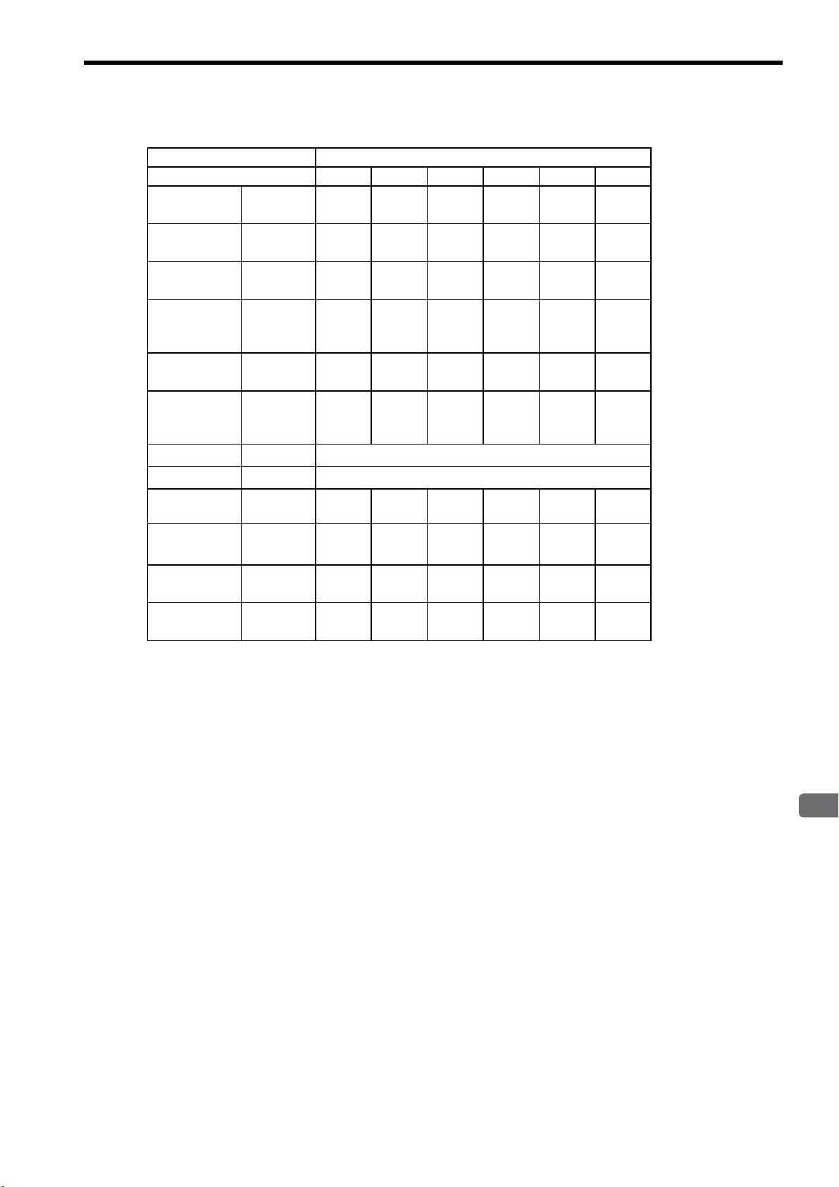
3.1 Ratings and Specifications of SGMVH (1500 min-1)
3
Servomotor Specifications and Dimensional Drawings
(b) 400 V Class
Voltage Class 400 V
Servomotor Model SGMVH- 2BDB3ZDB3GDB4EDB5EDB7EDB
Rated
Output
Rated
Torque
Stall
Torque
∗
∗
∗
kW
N·m
N·m
Instantaneous
Peak
Torque
Rated
Current
∗
∗
N·m
Arms
Instantaneous
Max.
Current
∗
Rated Speed ∗min
Max. Speed ∗min
Torque
Constant
Rotor Moment
of Inertia J
Rated Power
∗
Rate
Rated Angular
Acceleration
Arms
N·m/Arms
×10
kg·m2
kW/s
rad/s
∗
-1
-1
-4
2
* These items and torque-motor speed characteristics quoted in combination with SGDM/SGDH
SERVOPACK are at an armature winding temperature of 20°C.
Note: These characteristics are values with the following iron plate (heat sink) attached for
cooling.
SGMVH-2B, 3Z and 3G:
SGMVH-4E, 5E and 7E:
22 30 37 45 55 75
140 191 236 286 350 477
140 191 236 286 350 477
350 478 589
715
875 1193
44 60 76 102 117 150
120 170 230 280 340 450
1500
2000
3.44 3.44 3.36 3.09 3.15 3.35
366 498 595 1071 1290 1804
536 733 933 767 950 1265
3827 3536 3960 2675 2715 2645
650 × 650 × 35
740 × 520 × 27
mm
mm
3-3
Page 39

3 Servomotor Specifications and Dimensional Drawings
2000
1500
1000
500
0
0
100 200 300 400
SGMVH-2BAB SGMVH-3ZAB
2000
1500
1000
500
0
0
200 400 600
SGMVH-3GAB
2000
1500
1000
500
0
0
200 400 600
A
B
A
B
A
B
Torque (Nm)
Motor
speed
(min-1)
Torque (Nm)
Motor
speed
(min-1)
Torque (Nm)
Motor
speed
(min-1)
A
: Continuous Duty Zone
B
: Intermittent Duty Zone
(2) Torque-Motor Speed Characteristics (200 V class)
3-4
Page 40

3.1 Ratings and Specifications of SGMVH (1500 min-1)
3
Servomotor Specifications and Dimensional Drawings
(3) Torque-Motor Speed Characteristics (400 V class)
SGMVH-3ZDB
2000
SGMVH-2BDB
2000
Motor
speed
(min-1)
Motor
speed
(min-1)
1500
1000
500
0
2000
1500
1000
500
0
1500
Motor
speed
(min-1)
1000
AA
A
100 200 300 400
0
Torque (Nm)
SGMVH-3GDB
A
0
200 400 600
Torque (Nm)
B
500
0
2000
Motor
1500
speed
(min-1)
1000
B
500
0
0
0
A
200 400 600
Torque (Nm)
SGMVH-4EDB
A
A
200 400 600 800
Torque (Nm)
B
B
B
Motor
speed
(min-1)
2000
1500
1000
500
0
0
SGMVH-5EDB
A
A
300 600 900
Torque (Nm)
SGMVH-7EDB
2000
1500
Motor
speed
(min-1)
1000
B
B
500
0
0
AB
A
: Continuous Duty Zone
B
: Intermittent Duty Zone
400 800 1200
Torque (Nm)
3-5
Page 41

3 Servomotor Specifications and Dimensional Drawings
3.2 Ratings and Specifications of SGMVH (800 min-1)
(1) Ratings and Specifications
• Time Rating: Continuous
• Vibration Class: V15
• Insulation Resistance: 500 VDC, 10 MΩ min.
• Surrounding Air Temperature: 0 to 40°C
• Excitation: Permanent magnet
• Mounting: Flange-mounted (standard)
Foot-mounted (semi-standard)
(a) 200 V Class
Voltage Class 200 V
Servomotor Model
SGMVH-
Rated Output
Rated Torque
Stall Torque
∗
∗
∗
Instantaneous Peak Torque
Rated Current
∗
Instantaneous Max. Current
Rated Speed
Max. Speed
∗
∗
Torque Constant N·m/Arms
Rotor Moment of Inertia J
Rated Power Rate
∗
Rated Angular Acceleration ∗rad/s
Note: Refer to the next page for the notes.
∗
∗
kW
N·m
N·m
N·m
Arms
Arms
-1
min
-1
min
x10-4 kg·m
kW/s
2
• Thermal Class: F
• Withstand Voltage:
200 V Servomotors: 1500 VAC for one minute
400 V Servomotors: 1800 VAC for one minute
• Enclosure: Totally enclosed, cooled separately, IP44
• Ambient Humidity: 20% to 80% (no condensation)
• Drive Method: Timing belt or coupling
2BAD3ZAD3GAD
22 30 37
262 358 442
262 358 442
526 752 930
104 150 195
240 340 460
800
1300
2.73 2.50 2.34
2
705 1290 1564
979 994 1248
372627772824
3-6
Page 42
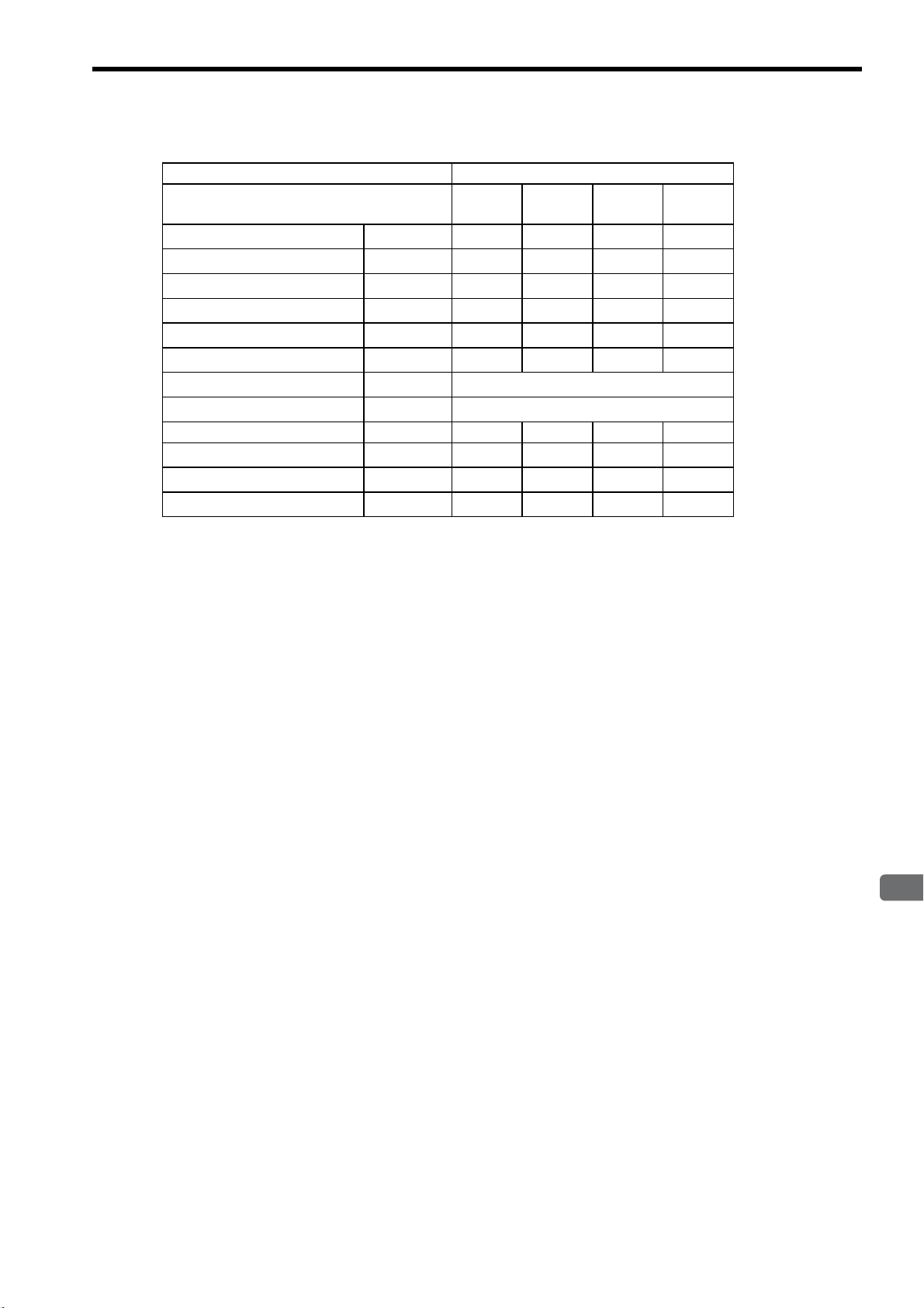
3.2 Ratings and Specifications of SGMVH (800 min-1)
3
Servomotor Specifications and Dimensional Drawings
(b) 400 V Class
Voltage Class 400 V
Servomotor Model
SGMVH-
Rated Output
Rated Torque
Stall Torque
∗
∗
∗
Instantaneous Peak Torque
Rated Current
∗
Instantaneous Max. Current
Rated Speed
Max. Speed
∗
∗
kW
N·m
N·m
∗
N·m
Arms
∗
Arms
-1
min
-1
min
Torque Constant N·m/Arms
Rotor Moment of Inertia J
Rated Power Rate
∗
Rated Angular Acceleration ∗rad/s
x10
kW/s
-4
2
kg·m2
* These items and torque-motor speed characteristics quoted in combination with SGDM/SGDH
SERVOPACK are at an armature winding temperature of 20°C.
Note: These characteristics are values with the following iron plates (heat sinks) attached for
cooling.
SGMVH-2B: 650 × 650 × 35 mm
SGMVH-3Z, 3G and 4E: 740 × 520 × 27 mm
2BDD3ZDD3GDD4EDD
22 30 37 45
262 358 442 537
262 358 442 537
526 752 930 1182
52 75 98 110
120 170 230 280
800
1300
5.46 5.00 4.68 5.21
705 1290 1564 1804
979 994 1248 1600
3726 2777 2824 2978
3-7
Page 43

3 Servomotor Specifications and Dimensional Drawings
1500
1000
500
0
0
200 400 600
SGMVH-2BAD
1500
1000
500
0
0
400 800 1200
SGMVH-3GAD
1500
1000
500
0
0
200 400 600
800
SGMVH-3ZAD
ABAB
AB
Motor
speed
(min
-1
)
Torque (Nm)
Motor
speed
(min-1)
Torque (Nm)
Motor
speed
(min
-1
)
Torque (Nm)
A
: Continuous Duty Zone
B
: Intermittent Duty Zone
2000
1500
1000
500
0
0
400 800 1200
SGMVH-3GDD
A
B
2000
1500
1000
500
0
0
200 400 600
SGMVH-2BDD
2000
1500
1000
500
0
0
200 400 600 800
SGMVH-3ZDD
A
B
2000
1500
1000
500
0
0
400
800
1200
SGMVH-4EDD
AB
B
A
B
A
B
A
B
A
Motor
speed
(min
-1
)
Torque (Nm)
Motor
speed
(min-1)
Torque (Nm)
Motor
speed
(min
-1
)
Torque (Nm)
Motor
speed
(min-1)
Torque (Nm)
A
: Continuous Duty Zone
B
: Intermittent Duty Zone
(2) Torque-Motor Speed Characteristics (200 V class)
(3) Torque-Motor Speed Characteristics (400 V class)
3-8
Page 44
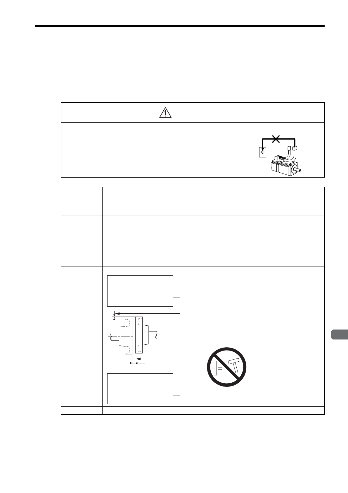
3
Servomotor Specifications and Dimensional Drawings
3.3 Mechanical Specifications of Servomotors
CAUTION
Do not connect
Measure this distance at four
different positions on the
circumference. The difference
between the maximum and
minimum measurements must be
0.06 mm or less.
(Turn together with coupling.)
Alignment Accuracy
Measure this distance at four
different positions on the
circumference. The difference
between the maximum and
minimum measurements must be
0.05 mm or less.
(Turn together with coupling.)
Alignment Accuracy
3.3.1 Precautions on Servomotor Installation
Servomotors can be installed either horizontally or vertically.
The service life of the servomotor will be shortened or unexpected problems will occur if the servomotor is
installed incorrectly or in an inappropriate location. Always observe the following installation instructions.
• Do not connect the servomotor directly to a commercial power line. This
will damage the servomotor.
The servomotor cannot operate without the proper SERVOPACK.
3.3 Mechanical Specifications of Servomotors
Storage
Temperature
and Humidity
Installation Site Servomotors are designed for indoor use. Install the servomotor in environments that satisfy the follow-
Alignment Align the shaft of the servomotor with the shaft of the
Store the servomotor within the following temperature range if it is stored with the power cable disconnected.
Surrounding air temperature during storage: -20 to 60°C
Ambient humidity during storage: 80%RH or less (with no condensation)
ing conditions.
• Free of corrosive or explosive gases.
• Well-ventilated and free of dust and moisture.
• Surrounding air temperature of 0 to 40°C
• Relative humidity of 20% to 80% with no condensation.
• Facilitates inspection and cleaning
equipment, and then couple the shafts. Install the servomotor so that alignment accuracy falls within the range
described on the left.
Vibration may occur and damage the bearings and the
encoder if the shafts are not correctly aligned.
Connect the servomotor to a machine in a way that prevents the application of concentric loads or rotary unbalanced loads on the motor shaft.
When installing, do not hit
the shafts with a hammer
etc., as impacts may result
in malfunction.
Orientation Servomotors can be installed either horizontally or vertically.
3-9
Page 45

3 Servomotor Specifications and Dimensional Drawings
Through shaft section:
Shaft
Flange
This refers to the gap where
the shaft protrudes from
the end of the motor.
IMPORTANT
Anticorrosive
paint is
coated here.
3.3.1 Precautions on Servomotor Installation
Handling Oil
and Water
If the servomotor is used in a location that is subject to
water drops, make sure of the servomotor protective
specifications (except for through shaft section).
If the servomotor is used in a location that is subject to
water or oil mist, use a servomotor with an oil seal to
seal the through shaft section.
Precautions on Using Servomotor With Oil Seal
• The oil surface must be under the oil seal lip.
• Use an oil seal in favorably lubricated condition.
• When using a servomotor with its shaft pointed
upward, be sure that oil will not stay in the oil seal
lips.
Cable Stress Make sure there are no bends or tension on the power lines.
Especially be careful to wire signal line cables so that they are not subject to stress because the core
wires are very thin at only 0.2 to 0.3 mm.
Connectors Observe the following precautions:
• Make sure there is no foreign matters such as dust and metal chips in the connector before connecting.
• When the connectors are connected to the motor, be sure to connect the end of servomotor main circuit cables before connecting the encoder cable’s end.
If the encoder cable’s end is connected first, the encoder may be damaged because of the voltage differences between frame grounds.
• Make sure of the pin arrangement.
• Do not apply shock to resin connectors. Otherwise, they may be damaged.
• When handling a servomotor with its cables connected, hold the servomotor or the connectors.
Otherwise, the cables will be damaged.
• When bending cables are used, wiring must be performed so that excessive stress will not be applied
to the connector section. Failure to observe this caution may damage the connector.
1. Before starting installation, thoroughly remove the anticorrosive paint that coats the end of the motor
shaft.
2. Vibration from improper alignment of shafts will damage the bearings.
3. Do not allow direct impact to be applied to the shafts when installing the coupling as the encoder
mounted on the opposite end of the shaft may be damaged.
3-10
Page 46
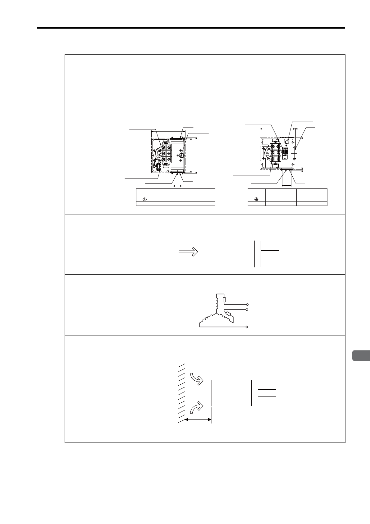
3.3 Mechanical Specifications of Servomotors
3
Servomotor Specifications and Dimensional Drawings
U
V
W
1
1b
Terminal Terminal Screw
M10
M10
1,1b M4Thermostat
Motor
Ground
Symbol
Terminal Terminal Screw
Thermostat
Motor
Ground
Symbol
U,V,W
230
236
249
φ
61
Plate
Plate
Ground bolt
Ground bolt
Terminal block
for motor leads
Terminal block
for motor leads
Plate
Plate
Terminal block
for thermostat
Terminal block
for thermostat
Motor lead exit
Motor lead exit
U,V,W
M10
M10
1,1b M4
220
(5)
φ
61
236
(5)
Unitsmm
7
8
9
D
U
V
W
Wring the Motor
Terminal Box
Wiring the
Servomotor
Fan
• Connect the servomotor power lines (U, V, and W) to the servomotor terminal block (M10) in the servomotor terminal box. Connect the ground wire to the ground bolt (M10) in the terminal box.
• The servomotor has a built-in thermostat. Wire the thermostat leads (l, lb) to the terminal block (M4)
in the servomotor’s terminal box.
• Terminal Box
• 22 kW to 37 kW (1500 min
• 22 kW (800 min
-1
)
-1
)
• 45 kW to 75 kW (1500 min
• 30 kW to 45 kW (800 min
-1
)
-1
)
Wire the servomotor fan leads U(A), V(B), and W(C) so that the direction of air flows according to the
following diagram. If the air flows in the opposite direction, change the wiring of any of the two phases
U, V, and W
.
Protecting the
Servomotor
Fan
Installing the
Servomotor
Fan
Servomotor
Direction of
cooling air
The servomotor fan has a built-in thermal protector, as shown in the following diagram, that operates at
140°C ±5%. To protect the servomotor fan from overcurrent, use with a 2-A no-fuse breaker.
To maximize the cooling capacity of the servomotor fan, install the fan at least 200 mm from the inlet
side of the servomotor as shown in the following diagram.
Cooling air
200 mm min.
Servomotor
3-11
Page 47

3 Servomotor Specifications and Dimensional Drawings
A
B
C
D
E
F
G
H
J
K
L
M
T
N
P
R
S
0V
+5VDC
DATA-
DATA+
BATTBATT+
AK
B
C
D
E
F
G
H
J
L
M
N
P
R
S
T
FG㧔Frame ground㧕
Plug: JA06A-20-29S-J1-EB
Cable clamp: JL04-2022CKE㧔㧕
Receptacle: 97F3102E20-29P
Applicable plug㧔purchased by a customer.㧕
--
-
-
-
-
-
-
-
-
#
$
%
&
'
(
)
*
,
-
.
/
6
0
2
4
5
0V
+5VDC
DATA-
DATA+
AK
B
C
D
E
F
G
H
J
L
M
N
P
R
S
T
--
-
-
-
-
-
-
-
-
-
-
FG㧔Frame ground㧕
Plug: JA06A-20-29S-J1-EB
Cable clamp: JL04-2022CKE㧔㧕
Receptacle: 97F3102E20-29P
Applicable plug㧔purchased by a customer.㧕
A
B
C
D
Fan terminal㧔㨁㧕
Fan terminal㧔㨂㧕
Fan terminal㧔㨃㧕
A
B
C
D
Plug: CE05-6A18-10SD-B-BSS
Cable clamp: CE3057-10A-㧔D265㧕
Receptacle: CE05-2A18-10PD-B
Applicable plug㧔purchased by a customer.㧕
3.3.1 Precautions on Servomotor Installation
Encoder-end
Connector
Specifications
Absolute Encoder
Incremental Encoder
Fan Connector
Specifications
3-12
Page 48

3
Servomotor Specifications and Dimensional Drawings
3.3.2 Allowable Radial and Thrust Loads
The following table shows the allowable loads applied to the SGMVH servomotor shaft end.
Design the mechanical system so radial and thrust loads applied to the servomotor shaft end during operation
falls within the ranges shown in the following table.
Note that even when using a servomotor below the allowable radial load, the following imbalance or the loads
may damage the bearings.
• The imbalance of parts that are connected to the shaft end
• Rotating loads generated by unmatched concentricity, when the bearing is attached to the extended shaft
end.
(1) 1500 min-1 Series
3.3 Mechanical Specifications of Servomotors
Servomotor Model
SGMVH-
2BAB, 2BDB
3ZAB, 3ZDB
3GAB, 3GDB
4EDB
5EDB
7EDB
Note: Allowable radial and thrust loads shown above are the maximum values that could be
applied to the shaft end from motor torque or other loads.
Allowable Radial Load
Fr [N]
5880 2156 100
6272 2156 100
7448 2156 100
7840 2156 100
8428 2156 110
10100 2156 120
Allowable Thrust
Load
Fs [N]
(2) 800 min-1 Series
Servomotor Model
SGMVH-
2BAD, 2BDD
3ZAD, 3ZDD
3GAD, 3GDD
4EDD
Note: Allowable radial and thrust loads shown above are the maximum values that could be
applied to the shaft end from motor torque or other loads.
Allowable Radial Load
Fr [N]
7448 2156 100
8428 2156 110
8428 2156 110
10100 2156 120
LR
Allowable Thrust
Load
Fs [N]
LR
[mm]
LR
[mm]
Fr
Fs
3-13
Page 49

3 Servomotor Specifications and Dimensional Drawings
A
B
C
Positive direction
Impact applied to the servomotor
Vertical
Front to back
Horizontal shaft
Side to side
3.3.3 Mechanical Tolerance
3.3.3 Mechanical Tolerance
The following table shows tolerances for the servomotor’s output shaft and installation area. For more details on
tolerances, refer to the dimensional drawing of the individual servomotor.
Tolerance T. I. R. (Total Indicator Reading) Reference Diagram
A
Perpendicularity between the flange face and output shaft : 0.05
B
Mating concentricity of the flange O.D. : 0.025
C
Run-out at the end of the shaft : 0.03
3.3.4 Direction of Servomotor Rotation
Positive rotation of the servomotor is counterclockwise when viewed from the load.
3.3.5 Impact Resistance
Mount the servomotor with the axis horizontal. The servomotor will withstand the following vertical impacts:
• Impact acceleration: 490 m/s
• Impact occurrences: 2
Vertical
Horizontal shaft
Impact applied to the servomotor
3.3.6 Vibration Resistance
Mount the servomotor with the axis horizontal. The servomotor will withstand the following vibration acceleration in three directions: Vertical, side to side, and front to back. The amount of vibration the servomotor endures
will vary depending on the application. Check the vibration acceleration being applied to your servomotor for
each application.
• Vibration acceleration: 24.5 m/s
2
2
3-14
Page 50

3
Servomotor Specifications and Dimensional Drawings
3.3.7 Vibration Class
TERMS
Position for measuring vibration
The vibration class 1for the servomotors at rated motor speed is as follows.
• Vibration class: V15
3.3 Mechanical Specifications of Servomotors
1
Vibration Class
A vibration class of V15 indicates a total vibration amplitude of 15 μm maximum on the servomotor during rated rotation.
3-15
Page 51

3 Servomotor Specifications and Dimensional Drawings
φ
265
φ
300
غ250
250
48
220
167
116
149
(Encoder, fan)
20 5
φ
230
0
-0.046
140
230
163
(Motor lead exit)
غ250
(Flange)
45 45
353
658
518
φ
60
+0.030
+0.011
144
94
147
Cooling air
Fan connector
Encoder
connector
4-
φ13.5
b
φ61
Motor lead exit
Opening for motor lead when
terminal box plate is replaced.
a
b
Hanging bolt
available
Units: mm
Approx. mass: 95 kg
d
c
d
c
a
φ0.05 A
0.05 A
A
0.03
140
5
7
140
R1.6
3.4 Dimensional Drawings of SGMVH Servomotors (1500 min-1)
22 kW (-2BAB, -2BDB)
(1)
• Shaft End Specifications
Specifications Shaft End
Straight, without key
Straight, with key and
tap *
* Shaft end key is a JIS B 1301-1996 horizontal key (key slot tightening type).
140
5
7
R1.6
140
110
0
18
-0.043
0
-0.110
11
M20 screw depth 40
7
3-16
Page 52
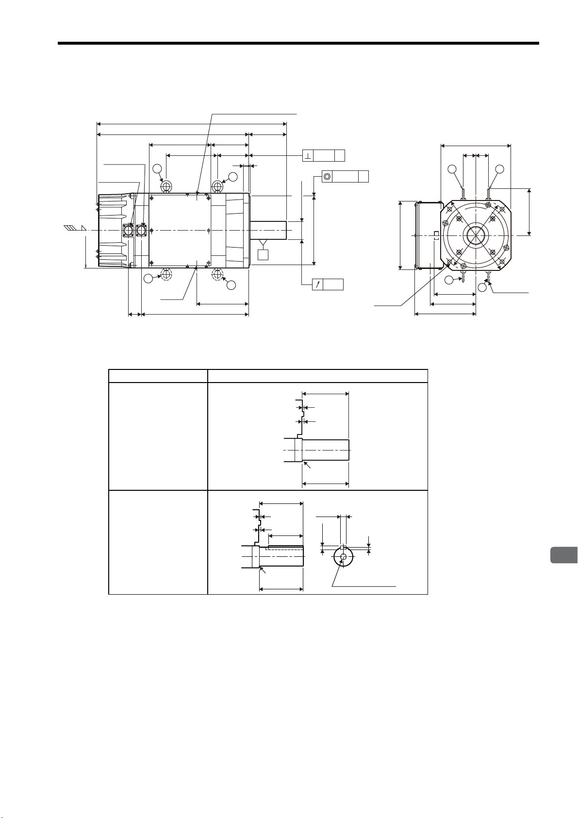
3
Servomotor Specifications and Dimensional Drawings
(2) 30 kW (-3ZAB, -3ZDB)
250
140564
704
116190
20
5
φ
60
+0.030
+0.011
φ
230
0
-0.046
193
399
48
140230
0.03
φ61
a
b
d
c
φ0.05 A
0.05 A
A
φ
265
φ
300
250
220
167
149
(Encoder, fan)
163
(Motor lead exit)
250
(Flange)
45 45
4-
φ13.5
a
b
d
c
Opening for motor lead when
terminal box plate is replaced.
Encoder
connector
Fan connector
Motor lead exit
Hanging bolt
available
Cooling air
Units: mm
Approx. mass: 110 kg
140
5
7
140
R1.6
140
5
7
140
110
7
R1.6
M20 screw depth 40
18
11
0
-0.110
0
-0.043
3.4 Dimensional Drawings of SGMVH Servomotors (1500 min-1)
• Shaft End Specifications
Specifications Shaft End
Straight, without key
Straight, with key and
tap *
* Shaft end key is a JIS B 1301-1996 horizontal key (key slot tightening type).
3-17
Page 53

3 Servomotor Specifications and Dimensional Drawings
φ
265
φ
300
250
220
167
149
(Encoder, fan)
163
(Motor lead exit)
250
(Flange)
45 45
250
48
φ
65
+0.030
+0.011
φ
230
0
-0.046
233
439
140
744
604
520
230
230 116
180
4-φ13.5
a
b
Hanging bolt
available
d
c
0.03
φ
61
d
c
a
b
φ0.05 A
0.05 A
A
Cooling air
Opening for motor lead when
terminal box plate is replaced.
Fan connector
Encoder
connector
Motor lead exit
Units: mm
Approx. mass: 120 kg
(3) 37 kW (-3GAB, -3GDB)
• Shaft End Specifications
Specifications Shaft End
Straight, without key
Straight, with key and
tap *
5
7
R1.2
140
110
140
* Shaft end key is a JIS B 1301-1996 horizontal key (key slot tightening type).
5
7
R1.2
18
140
140
0
0
-0.043
-0.110
11
M20 screw depth 40
7
3-18
Page 54

3
Servomotor Specifications and Dimensional Drawings
(4) 45 kW (-4EDB)
φ
300
φ
350
300
220
530
φ75
+0.030
+0.011
φ250
0
-0.046
437
35
145652
797
222236
280
(Flange)
3030
174
(Encoder, fan)
487
277
48
201
(Motor lead exit)
210
258
Cooling air
Motor lead exit
a
b
a
b
0.03
Opening for motor lead
when terminal box plate
is replaced.
c
d
φ61
d
Hanging bolt
available
c
Fan connector
Encoder connector
4-φ17.5
0.05 A
A
φ0.05 A
Units: mm
Approx. mass: 165 kg
5
5
145
140
R2.5
3.4 Dimensional Drawings of SGMVH Servomotors (1500 min-1)
• Shaft End Specifications
Specifications Shaft End
Straight, without key
Straight, with key and
tap *
* Shaft end key is a JIS B 1301-1996 horizontal key (key slot tightening type).
145
5
5
R2.5
110
0
20
-0.052
0
-0.110
12
M20 screw depth 40
7.5
140
3-19
Page 55

3 Servomotor Specifications and Dimensional Drawings
φ
300
φ
350
220
280
(Flange)
3030
174
(Encoder, fan)
258
201
(Motor lead exit)
210
300
5
145697
842
267236
482
35
30
φ
75
+0.030
+0.011
φ
250
0
-0.046
532
322
48
a
b
Opening for motor lead
when terminal box plate
is replaced.
d
Hanging bolt
available
c
Cooling air
Motor lead exit
0.03
a
b
c
d
φ
61
4-φ17.5
Encoder connector
Fan connector
0.05
A
A
φ
0.05
A
Units: mm
Approx. mass: 185 kg
5
5
145
140
R2.5
(5) 55 kW (-5EDB)
• Shaft End Specifications
Specifications Shaft End
Straight, without key
Straight, with key and
tap *
* Shaft end key is a JIS B 1301-1996 horizontal key (key slot tightening type).
5
5
R2.5
145
140
110
0
20
-0.052
0
-0.110
12
M20 screw depth 40
7.5
3-20
Page 56

3
Servomotor Specifications and Dimensional Drawings
(6) 75 kW (-7EDB)
300
220
30 5
35
175
973
798
572
357
φ
85
+0.035
+0.013
φ
250
0
-0.046
236
30 30
280
(Flange)
210
258
201
(Motor lead exit)
174
(Encoder, fan)
622
48
412
φ
300
φ
350
a
Opening for motor lead
when terminal box plate
is replaced.
d
Hanging bolt
available
c
Cooling air
a
c
d
Motor lead exit
0.03
0.05
A
φ0.05
A
b
b
φ
61
Encoder
connector
Fan connector
4-φ17.5
A
Units: mm
Approx. mass: 225 kg
5
5
175
170
R2.5
• Shaft End Specifications
3.4 Dimensional Drawings of SGMVH Servomotors (1500 min-1)
Specifications Shaft End
Straight, without key
Straight, with key and
tap *
5
5
175
R2.5
170
140
0
22
-0.052
0
-0.110
14
M20screw depth 40
9
* Shaft end key is a JIS B 1301-1996 horizontal key (key slot tightening type).
3-21
Page 57

3 Servomotor Specifications and Dimensional Drawings
250
φ
265
φ
300
250
220
167
149
(Encoder, fan)
163
(Motor lead exit)
250
(Flange)
45 45
140
116
20 5
φ
230
0
-0.046
48
230
φ
65
+0.030
+0.011
794
654
230
283
489
280
Fan connector
Encoder
connector
Motor lead exit
4-φ13.5
a
b
Hanging bolt
available
d
c
0.03
φ
61
a
b
d
c
φ0.05 A
0.05 A
A
Cooling air
Opening for motor lead when
terminal box plate is replaced.
Units: mm
Approx. mass: 135 kg
5
7
7
140
140
110
M20 screw depth 40
R1.2
18
11
0
-0.110
0
-0.043
3.5 Dimensional Drawings of SGMVH Servomotors (800 min-1)
(1) 22 kW (-2BAD, -2BDD)
• Shaft End Specifications
Specifications Shaft End
Straight, without key
Straight, with key and
tap *
* Shaft end key is a JIS B 1301-1996 horizontal key (key slot tightening type).
140
5
7
R1.2
140
3-22
Page 58

3
Servomotor Specifications and Dimensional Drawings
(2) 30 kW (-3ZAD, -3ZDD)
φ
300
φ
350
220
280
(Flange)
3030
174
(Encoder, fan)
201
(Motor lead exit)
210
300
5
145697
842
267236
482
35
30
φ
75
+0.030
+0.011
φ
250
0
-0.046
532
322
48
258
a
b
Opening for motor lead
when terminal box plate
is replaced.
d
Hanging bolt
available
c
Cooling air
Motor lead exit
0.03
a
b
c
d
φ61
4-φ17.5
Encoder
connector
Fan connector
0.05 A
A
φ0.05 A
Units: mm
Approx. mass: 185 kg
3.5 Dimensional Drawings of SGMVH Servomotors (800 min-1)
• Shaft End Specifications
Specifications Shaft End
Straight, without key
Straight, with key and
tap *
5
5
R2.5
145
110
140
* Shaft end key is a JIS B 1301-1996 horizontal key (key slot tightening type).
5
5
145
R2.5
140
20
0
0
-0.052
-0.110
12
screw depth 40
M20
7.5
3-23
Page 59

3 Servomotor Specifications and Dimensional Drawings
φ
300
φ
350
220
280
(Flange)
3030
174
(Encoder, fan)
201
(Motor lead exit)
210
300
5
145
236
35
30
φ
75
+0.030
+0.011
φ
250
0
-0.046
48
372
582
317
532
747
892
258
a
b
Opening for motor lead
when terminal box plate
is replaced.
d
Hanging bolt
available
c
Cooling air
Motor lead exit
0.03
a
b
c
d
φ61
4-φ17.5
Encoder
connector
Fan connector
0.05 A
A
φ0.05 A
Units: mm
Approx. mass: 205 kg
5
5
145
140
R2.5
5
145
140
5
7.5
110
R2.5
M20
screw depth 40
20
12
0
-0.110
0
-0.052
(3) 37 kW (-3GAD, -3GDD)
• Shaft End Specifications
Specifications Shaft End
Straight, without key
Straight, with key and
tap *
* Shaft end key is a JIS B 1301-1996 horizontal key (key slot tightening type).
3-24
Page 60

3
Servomotor Specifications and Dimensional Drawings
(4) 45 kW (-4EDD)
5
170
5
140
175
9
R2.5
M20 screw depth 40
22
14
0
-0.110
0
-0.052
236 357
Fan connector
b
Encoder
connector
973
572
798
3.5 Dimensional Drawings of SGMVH Servomotors (800 min-1)
175
A
35
5
30
a
0.05
φ
Opening for motor lead
when terminal box plate
is replaced.
0.05
A
280
(Flange)
30 30
a
b
Cooling air
300
Motor lead exit
d
48
φ61
• Shaft End Specifications
Specifications Shaft End
Straight, without key
Straight, with key and
tap *
622
412
φ
d
174
(Encoder, fan)
201
(Motor lead exit)
258
350
+0.035
+0.013
85
0
-0.046
φ
250
φ
A
c
0.03
220
4-φ17.5
φ
300
c
Hanging bolt
available
210
Units: mm
Approx. mass: 225 kg
175
5
5
R2.5
170
* Shaft end key is a JIS B 1301-1996 horizontal key (key slot tightening type).
3-25
Page 61

4
SERVOPACK Specifications and Dimensional Drawings
4
SERVOPACK Specifications and
Dimensional Drawings
4.1 SERVOPACK Ratings and Specifications - - - - - - - - - - - - - - 4-2
4.1.1 Three-phase 200 V - - - - - - - - - - - - - - - - - - - - - - - - - - - - - - - - - - - - 4-2
4.1.2 Three-phase 400 V - - - - - - - - - - - - - - - - - - - - - - - - - - - - - - - - - - - - 4-2
4.1.3 SERVOPACK Ratings and Specific
4.2 SERVOPACK Installation - - - - - - - - - - - - - - - - - - - - - - - - - - 4-5
4.3 SERVOPACK Internal Block Diagrams - - - - - - - - - - - - - - - - 4-7
4.3.1 Three-phase 200 V, 22 kW, 30 kW Models - - - - - - - - - - - - - - - - - - - - 4-7
4.3.2 Three-phase 200 V, 37 kW Model - - - - - - - - - - - - - - - - - - - - - - - - - - 4-8
4.3.3 Three-phase
4.3.4 Three-phase
4.3.5 Three-phase
4.3.6 Three-phase 400 V, 90 kW Model - - - - - - - - - - - - - - - - - - - - - - - - - 4-10
400 V, 22 kW, 30 kW Models
400 V, 37 kW Model
400 V, 45 kW, 55 kW Models
ations
- - - - - - - - - - - - - - - - - - - - - 4-3
- - - - - - - - - - - - - - - - - - - - 4-9
- - - - - - - - - - - - - - - - - - - - - - - - - - 4-9
- - - - - - - - - - - - - - - - - - - 4-10
4.4 SERVOPACK’s Power Supply Capacities and Power Losses 4-11
4.5 SERVOPACK Overload Characteristics and Allowable Load
Moment of Inertia - - - - - - - - - - - - - - - - - - - - - - - - - - - - - - 4-12
4.5.1 Overload Characteristics - - - - - - - - - - - - - - - - - - - - - - - - - - - - - - - 4-12
4.5.2 Starting and Stopping Time - - - - - - - - - - - - - - - - - - - - - - - - - - - - - - 4-13
4.5.3 Load Moment of Inertia - - - - - - - - - - - - - - - - - - - - - - - - - - - - - - - - 4-14
4.6 SERVOPACK Dimensional Drawings - - - - - - - - - - - - - - - - 4-16
4.6.1 Three-phase 200 V, 22 kW, 30 kW Models - - - - - - - - - - - - - - - - - - - 4-16
4.6.2 Three-phase 200 V, 37 kW Model - - - - - - - - - - - - - - - - - - - - - - - - - 4-17
4.6.3 Three-phase 400 V, 22 kW Model - - - - - - - - - - - - - - - - - - - - - - - - - 4-18
Three-phase 400 V, 30 kW Model
4.6.4
4.6.5 Three-phase 400 V, 37 kW Model - - - - - - - - - - - - - - - - - - - - - - - - - 4-20
4.6.6 Three-phase 400 V, 45 kW, 55 kW Models - - - - - - - - - - - - - - - - - - - 4-20
4.6.7 Three-phase 400 V, 90 kW Model - - - - - - - - - - - - - - - - - - - - - - - - - 4-21
- - - - - - - - - - - - - - - - - - - - - - - - - 4-19
4-1
Page 62

4 SERVOPACK Specifications and Dimensional Drawings
CAUTION
4.1.1 Three-phase 200 V
4.1 SERVOPACK Ratings and Specifications
• Take appropriate measures to ensure that the input power supply is supplied within the specified voltage
range.
An incorrect input power supply may result in damage to the SERVOPACK. If the voltage exceeds these values, use
a step-down transformer so that the voltage will be within the specified range.
4.1.1 Three-phase 200 V
The value of the input power supply voltage is maximum 253 Vrms.
SERVOPACK
Model
Max. Applicable Servomotor Capacity (kW)
Continuous Output Current (Arms)
Max. Output Current (Arms)
Input Power Supply Main Circuit Three-phase 200 to 230 VAC +10% to -15%, 50/60 Hz
Control Circuit Single-phase 200 to 220 VAC +10% to -15%, 50 Hz
Configuration Base-mounted
4.1.2 Three-phase 400 V
The value of the input power supply voltage is maximum 528 Vrms.
SERVOPACK Model SGDH- 2BDEB 3ZDEB 3GDEB 4EDEB 5EDEB 9ZDEB
Max. Applicable Servomotor Capacity (kW)
Continuous Output Current (Arms)
Max. Output Current (Arms)
Input Power Supply Main Circuit Three-phase 380 to 480 VAC +10% to -15%, 50/60 Hz
Control Circuit 24 VDC ±15%
For Control Actuator Single-phase 380 to 480 VAC, 50/60 Hz, 150 VA
Configuration Base-mounted
SGDM- 2BADB 3ZADB 3GADB
SGDH- 2BAEB 3ZAEB 3GAEB
22 30 37
110 148 195
240 340 460
Single-phase 200 to 230 VAC +10% to -15%, 60 Hz
22 30 37 45 55 75
52.2 75 98 127 150 210
120 170 230 280 340 580
4-2
Page 63

4.1 SERVOPACK Ratings and Specifications
4
SERVOPACK Specifications and Dimensional Drawings
4.1.3 SERVOPACK Ratings and Specific
Basic
Specifications
Speed
and
Torque
Control
Modes
Position
Control
Modes
I/O
Signals
Control Method Three-phase full-wave rectification IGBT-PWM (sine-wave driven)
Feedback Serial encoder: 17-bit (incremental/absolute)
Conditions
Ambient/Storage Temperature
Ambient/Storage Humidity 90% RH or less (with no condensation)
∗1
Vibration/Shock Resistance
Perfor-
Speed Control Range 1:5000 (The lowest speed of the speed control range is the speed at which
mance
Speed
Regula-
∗2
tion
Load Regulation 0 to 100% load: ±0.01% or less (at rated speed)
Voltage Regulation Rated voltage ±10%: 0% (at rated speed)
Temperature Regulation
Frequency Characteristics 100 Hz (at JL = JM)
Torque Control Tolerance
(Repeatability)
Soft Start Time Setting 0 to 10 s (Can be set individually for acceleration and deceleration.)
Input
Signals
Speed
Reference
Reference Voltage
∗3
Input
Input Impedance About 14 kΩ
Circuit Time Constant About 47 μs
To rq u e
Reference Voltage
∗3
Reference
Input
Input Impedance About 14 kΩ
Circuit Time Constant About 47 μs
Performance
Contact
Speed
Reference
Bias Setting
Feed Forward Compensation 0 to 100% (setting resolution: 1%)
Rotation Direction
Selection
Speed Selection With forward/reverse external torque limit signal (speed 1 to 3 selection),
Positioning Completed Width
Setting
Input
Signals
Reference
Pulse
Type Sign + pulse train, 90° phase difference 2-phase pulse train (phase A +
Form Line driver (+5 V level), open collector (+5 V or +12 V level)
Frequency Maximum 500/200 kpps (line driver/open collector)
Control Signal Clear signal (input pulse form identical to reference pulse)
Built-in Open Collector Power
Supply
∗4
Position Output Form Phase-A, -B, -C line driver
Frequency Dividing
Ratio
Sequence Input Signal allocation can
be modified.
Sequence Output Fixed Output Servo alarm, 3-bit alarm codes
Signal allocation can
be modified.
ations
0 to +55°C/-20 to +85°C
2
/19.6 m/s
4.9 m/s
the servomotor will not stop with a rated torque load.)
25 ± 25°C: ±0.1% or less (at rated speed)
±2%
±6 VDC (Variable setting range: ±2 to ±10 VDC) at rated speed, input
voltage: maximum ±12 V (servomotor forward rotation with positive
reference)
±3 VDC (Variable setting range: ±1 to ±10 VDC) at rated torque, input
voltage: maximum ±12 V (positive torque reference with positive
reference)
With P control signal
servomotor stops or another control method is used when both are OFF.
0 to 450 min
0 to 250 reference units (setting resolution: 1 reference unit)
phase B), or CCW + CW pulse train
+12 V (1kΩ resistor built in)
Phase-S line driver (only with an absolute encoder)
Any
Servo ON, P control (or Control mode switching, forward/reverse motor
rotation by internal speed setting, zero clamping, reference pulse prohibited), forward run prohibited (P-OT), reverse run prohibited (N-OT),
alarm reset, forward external torque limit, and reverse external torque
limit (or internal speed selection)
Select three signals from the following: Positioning completed (speed
coincidence), servomotor rotation detection, servo ready, torque limit,
speed limit, brake interlock, warning, NEAR signal.
2
-1
(setting resolution: 1 min-1)
4-3
Page 64

4 SERVOPACK Specifications and Dimensional Drawings
Speed reguration
=
No-load motor speed – Total load motor speed
Rated motor speed
× 100%
4.1.3 SERVOPACK Ratings and Specific
ations
Internal
Functions
Dynamic Brake Operated at main power OFF, servo alarm, servo OFF or overtravel.
Overtravel Stop Dynamic brake stop at P-OT or N-OT, deceleration to a stop, or coast to a
stop
Electronic Gear 0.01 ≤ B/A ≤ 100
Protection Overcurrent, overvoltage, low voltage, overload, regeneration error, main
circuit detection section error, heat sink overheated, no power supply,
overflow, overspeed, encoder error, overrun, CPU error, parameter error
LED Display Charge, Power, five 7-segment LEDs × 5 digits (built-in Digital Operator
functions)
CN5Analog Monitoring Analog monitor connector built in for monitoring speed, torque and other
reference signals.
Speed: 1 V/1000 min
-1
Torque: 1 V/ rated torque
Position error pulses: 0.05 V/1 reference units or 0.05 V/100 reference
units
Communications Connected Devices Digital Operator (hand-held model), RS-422A port such as for a personal
computer (RS-232C ports under certain conditions)
1:N Communications Up to N = 14 for RS-422A ports
Axis Address Setting Set with parameters.
Functions Status display, parameter setting, monitor display, alarm trace-back dis-
play, JOG operations, speed/torque reference signal and other drawing
functions
Others Reverse rotation connection, zero-point search, automatic servomotor ID,
DC reactor connection terminal for harmonic suppressions
* 1. Use the SERVOPACK within the surrounding air temperature range. When enclosed in a control
panel, internal temperatures must not exceed the ambient temperature range.
* 2. Speed regulation is defined as follows:
The motor speed may change due to voltage variations or amplifier drift and changes in processing
resistance due to temperature variation. The ratio of speed changes to the rated speed represent speed
regulation due to voltage and temperature variations.
* 3. Forward is clockwise viewed from the non-load side of the servomotor. (Counterclockwise viewed
from the load and shaft end)
* 4. The built-in open collector power supply is not electrically insulated from the control circuit in the
SERVOPACK.
4-4
Page 65

4.2 SERVOPACK Installation
4
SERVOPACK Specifications and Dimensional Drawings
WARNING
4.2 SERVOPACK Installation
The SGDM/SGDH SERVOPACKs can be mounted on a base. Incorrect installation will cause problems. Always
observe the following installation instructions.
• After voltage resistance test, wait at least five minutes before servicing the product. (Refer to “Voltage Resistance Test” on the following page.)
Failure to observe this warning may result in electric shock.
• Connect the main circuit wires, control wires, and main circuit cables of the motor correctly.
Incorrect wiring will result in failure of the SERVOPACK.
Storage Store the SERVOPACK within the following temperature range if it is stored with the power cable discon-
nected.
Temperature: -20 to 85°C
Humidity: 90% RH or less (with no condensation)
Installation Site Installation in a Control Panel
Design the control panel size, unit layout, and cooling method so the temperature around the SERVOPACK
does not exceed 55°C.
Installation Near a Heating Unit
Minimize the heat radiating from the heating unit as well as any temperature rise caused by natural convection so the temperature around the SERVOPACK does not exceed 55 °C.
Installation Near a Source of Vibration
Install a vibration isolator on the SERVOPACK to avoid subjecting it to vibration.
Installation at a Site Exposed to Corrosive Gas
Corrosive gas does not have an immediate effect on the SERVOPACK but will eventually cause the electronic components and contactor-related devices to malfunction. Take appropriate action to avoid corrosive
gas.
Other Situations
Do not install the SERVOPACK in hot, humid locations or locations subject to water, cutting oil, excessive
dust, iron powder, and radioactivity in the air.
Orientation Install the SERVOPACK perpendicular to the wall as shown in the figure.
50 mm min.
(ventilation exhaust)
POWER
8CN
O
P
E
R
A
T
O
R
T DATA/SEEMOD/
CN5
CN3
ෂޓ㒾
WARNING
ᗵ㔚ߩᕟࠇࠅ
ㅢ㔚߮㔚Ḯࠝࡈᓟ5
ಽ㑆ޔ┵ሶㇱߦ⸅ࠆߥ!
May cause
electric shock.
Disconnect all power
and wait 5 min.
before servicing.
ᔅߕࠕ㧙ࠬ✢ࠍ
ធ⛯ߖࠃ
Use proper
grounding techniques.
DC
480 V460
400 V 0 V440
380
DU
DWDV B1
B2
24N
V
V
V
CHARGE
L1/R L2/S
+2-+1
DC
24P
L3/T
S-HDG
UVW
KSERVOPAC
㧖㧖㧖㧖
AYASKAW
50 mm min.
50 mm min.
50 mm min. (ventilation intake)
120 mm min.
120 mm min.
Air flow
Air flow
4-5
Page 66

4 SERVOPACK Specifications and Dimensional Drawings
Fan
50 mm min.
100 mm min.
120 mm
min.
120 mm
min.
Fan
.4 .5
.6
789
8
8
&7
88
8
&9&8 $
8
&%
0
$
&%
2
%*#4)'
5*&)
㧖㧖㧖㧖
6#5''/1&
-5'4812#%
#;#5-#9
4
1
2
'
4
#
6
1
%0
%0
219'4
%0
WARNING
ෂޓ㒾
ㅢ㔚߮㔚Ḯࠝࡈᓟ5
ಽ㑆ޔ┵ሶㇱߦ⸅ࠆߥ
electric shock.
Disconnect all power
May cause
ᗵ㔚ߩᕟࠇࠅ
before servicing.
and wait 5 min.
grounding techniques.
ធ⛯ߖࠃ
Use proper
ᔅߕࠕ㧙ࠬ✢ࠍ
.4 .5
.6
789
8
8
&7
88
8
&9&8 $
8
&%
0
$
&%
2
%*#4)'
5*&)
㧖㧖㧖㧖
6#5''/1&
-5'4812#%
#;#5-#9
4
1
2
'
4
#
6
1
%0
%0
219'4
%0
WARNING
ෂޓ㒾
ㅢ㔚߮㔚Ḯࠝࡈᓟ5
ಽ㑆ޔ┵ሶㇱߦ⸅ࠆߥ
electric shock.
Disconnect all power
May cause
ᗵ㔚ߩᕟࠇࠅ
before servicing.
and wait 5 min.
grounding techniques.
ធ⛯ߖࠃ
Use proper
ᔅߕࠕ㧙ࠬ✢ࠍ
.4 .5
.6
789
8
8
&7
88
8
&9&8 $
8
&%
0
$
&%
2
%*#4)'
5*&)
㧖㧖㧖㧖
6#5''/1&
-5'4812#%
#;#5-#9
4
1
2
'
4
#
6
1
%0
%0
219'4
%0
WARNING
ෂޓ㒾
ㅢ㔚߮㔚Ḯࠝࡈᓟ5
ಽ㑆ޔ┵ሶㇱߦ⸅ࠆߥ
electric shock.
Disconnect all power
May cause
ᗵ㔚ߩᕟࠇࠅ
before servicing.
and wait 5 min.
grounding techniques.
ធ⛯ߖࠃ
Use proper
ᔅߕࠕ㧙ࠬ✢ࠍ
.4 .5
.6
789
8
8
&7
88
8
&9&8 $
8
&%
0
$
&%
2
%*#4)'
5*&)
㧖㧖㧖㧖
6#5''/1&
-5'4812#%
#;#5-#9
4
1
2
'
4
#
6
1
%0
%0
219'4
%0
WARNING
ෂޓ㒾
ㅢ㔚߮㔚Ḯࠝࡈᓟ5
ಽ㑆ޔ┵ሶㇱߦ⸅ࠆߥ
electric shock.
Disconnect all power
May cause
ᗵ㔚ߩᕟࠇࠅ
before servicing.
and wait 5 min.
grounding techniques.
ធ⛯ߖࠃ
Use proper
ᔅߕࠕ㧙ࠬ✢ࠍ
Installation Follow the procedure below to install multiple SERVOPACKs side by side in a control panel.
SERVOPACK Orientation
Install the SERVOPACK perpendicular to the wall so the front panel containing connectors faces outward.
Cooling
As shown in the figure above, allow sufficient space around each SERVOPACK for cooling by cooling fans
or natural convection.
Side-by-side Installation
When installing SERVOPACKs side by side as shown in the figure above, allow at least 100 mm between
and at least 120 mm above and below each SERVOPACK. Allow the space for eyebolts on both sides of the
SERVOPACK.
Environmental Conditions in the Control Panel
Surrounding Air Temperature:0 to 55°C
Humidity: 90% RH or less
Vibration: 4.9 m/s
2
Condensation and Freezing: None
Surrounding Air Temperature for Long-term Reliability: 45°C or less
Voltage
Resistance Test
Conduct voltage resistance tests under the following conditions.
• Voltage: 1500 Vrms AC for one minute
• Braking current: 100 mA
• Frequency: 50 or 60 Hz
• Voltage applied points
200 V series: Between the ground terminals and the point where terminals L1C/r, L3C/t, L1/R, L2/S, L3/T
are connected.
400 V series: Between the ground terminals and the point where terminals 480 V, 460 V, 440 V, 400 V, 380 V,
0 V, L1/R, L2/S, L3/T are connected.
4-6
Page 67

4
SERVOPACK Specifications and Dimensional Drawings
4.3 SERVOPACK Internal Block Diagrams
FIL
R
S
T
1KM
L1/R
+ 1
+ 2
R1
B1
TRM7
TRM1 to
TRM6
FU1 to 3
C1 to
C4
B2
+
-
CHARGE
SA1 to SA3
3PWB
200 VAC
1KM
1KM
(5Ry) Open during servo alarm
1CN
3CN
L1C/r
L3C/t
+5V
2PWB
2CN
PG
L2/S
L3/T
-
200 VAC
DCCT1
DCCT2
DCCT3
MC2
DU
DV
DW
U
V
W
U
RST
UVW
V
W
M
200
VAC
MC1
MC1
FAN
㨪ޓ
㨪ޓ
FAN1 to FAN2
1QF
Servomotor
Three-phase
200 to 230 VAC
(50/60 Hz)
Regenerative resistor (option)
DB resistor (option)
From
detection
circuit
From detection
circuit
DC/DC
converter
Power for
drive
Drive circuit
Current sensor
Sensor circuit
Position/speed calculation circuit
Control input
Digital operator
(personal computer)
Power OFF
Power ON
Surge absorber
4.3 SERVOPACK Internal Block Diagrams
4.3.1
Three-phase 200 V, 22 kW, 30 kW Models
4-7
Page 68

4 SERVOPACK Specifications and Dimensional Drawings
4.3.2 Three-phase 200 V, 37 kW Model
4.3.2 Three-phase 200 V, 37 kW Model
Three-phase
200 to 230 VAC
(50/60 Hz)
1QF
R
S
T
FIL
1KM
+ 1
+ 2
L1/R
L2/S
L3/T
SA1 to SA3
-
R2
R1
MC1
200
VAC
From detection
circuit
CHARGE
MC1
Regenerative resistor (option)
B1
B2
TRM1
to
TRM6
TRM7
C1 to
C4
+
-
FU1 to 3
DU DV DW
DB resistor
(option)
From detection
circuit
DCCT1
DCCT2
DCCT3
DB unit
(option)
RST
UVW
FAN
U
U
V
V
M
W
W
L1C/r
L3C/t
Power OFF
(5Ry) Open during servo alarm
3PWB
㨪ޓ
㨪ޓ
Power ON
1KM
200 VAC
FAN1 to FAN2
DC/DC
converter
Control input
Digital operator
(personal computer)
1KM
Surge absorber
+5V
Power for
drive
1CN
3CN
2PWB
Drive circuit
Sensor circuit
Position/speed calculation circuit
Current sensor
2CN
PG
Servomotor
4-8
Page 69

4.3 SERVOPACK Internal Block Diagrams
4
SERVOPACK Specifications and Dimensional Drawings
D/A
A/D
I/O
CN5 CN3
CN10
CN2
CN8
CN1
1PCB
2PCB
+
-
+5V
+24V
+15V
43CN
3PCB
200 VAC
FAN1
215V
1
2
3
4
480V
460V
440V
400V
380V
0V
600V 4A
0
E
DC24P
DC24N
DU
DV
DW
MC2
DCCT1
DB24DBON
W
V
U
W
V
U
DCCT2
DCCT3
DB24
DBON
R
T
S
+-+
-
+-+
-
TRM1 to TRM6
C1 to C4
TRM7
+
-
+
-
CHARGE
MC1
MC1
R1
200 VAC
C64
C65
C61 to C63
L1/R
DM1
to DM3
PG
1
2
-
L2/S
L3/T
B1 B2
+
+
FU1
FU4
MC2
SA1 to SA3
Digital operator
DC reactor
connection
terminals
Main circuit power
input terminals
(380 to 480 VAC)
Main circuit
minus terminal
Control power
input terminals
(24 VDC)
Control power
input terminals
(380 to 480 VAC)
Ground terminal
Ground terminal
VaristorVari st or
Varistor
DC/DC
converter
Voltage sensor
Relay drive Voltage sensor
Voltage sensor
gate drive
Gate drive
Interface
Regenerative resistor
Regenerative resistor
unit connection terminals
Motor
connection
terminals
Thermostat 1 Thermostat 2
Panel operator
(Option unit)
ASIC (PWM control, etc.)
CPU
(Position/speed calculation, etc.)
Current sensor
Battery
PG output
Reference pulse
input
Speed/torque
reference input
Sequence input
Analog monitor
Dynamic
brake
unit
connection
terminals
D/A
A/D
I/O
CN5 CN3
CN10
CN2
CN8
CN1
1PCB
2PCB
+
-
+5V
+24V
+15V
43CN
3PCB
DC24P
DC24N
DU
DV
DW
KM
DCCT1
DB24
DBON
W
V
U
W
V
U
DCCT2
DCCT3
DB24
DBON
R
T
S
+-+
-
+-+
-
TRM1 to TRM6
C1 to C4
TRM7
+
-
+
-
CHARGE
MC1
MC1
R1
200 VAC
DM1 to DM3
C64
C65
C61 to C63
L1/R
1
2
-
L2/S
L3/T
B1 B2
+
+
FU1
FU4
FAN1
215V
1
2
3
4
480V
460V
440V
400V
380V
0V
600V 4A
0
E
FAN2
5
6
200 VAC
SA1 to SA3
DU DV DW
KM
R2
Panel operator
PG
Digital operator
DC reactor
connection
terminals
Main circuit power
input terminals
(380 to 480 VAC)
Main circuit
minus terminal
Control power
input terminals
(24 VDC)
Control power
input terminals
(380 to 480 VAC)
Ground terminal
Ground terminal
Varistor
VaristorVa ri sto r
DC/DC
converter
Voltage sensor
Relay drive
Voltage sensor
Voltage sensor
gate drive
Gate drive
Interface
Regenerative resistor
Regenerative resistor
unit connection terminals
Motor
connection
terminals
Thermostat 1
Thermostat 2
(Option unit)
ASIC (PWM control, etc.)
CPU
(Position/speed calculation, etc.)
Battery
PG output
Reference pulse
input
Speed/torque
reference input
Sequence input
Analog monitor
Current sensor
4.3.3
Three-phase
400 V, 22 kW, 30 kW Models
4.3.4
Three-phase
400 V, 37 kW Model
4-9
Page 70

4 SERVOPACK Specifications and Dimensional Drawings
+
+
-
1
2
L1/R
SA1 to SA3
DM1 to DM6
C1 to C6
L2/S
L3/T
DC24P
2PCB
3PCB
1PCB
DC24N
480 V
460 V
440 V
400 V
380 V
FU5
0 V
R
R1
MC1
MC1
S
T
200 VAC
CHARGE
B1 B2
TRM13
TRM1 to TRM12
FU2 FU1
U
V
W
U
V
W
KM
DU
DV
DW
DU DV DW
DCCT1
DCCT2
DCCT3
DBON DB24
+5 V
+24 V
+15 V
200 VAC
FAN1
FAN2
CN10
CN5 CN3
CN2
CN8
CN1
D/A
A/D
I/O
Thermostat
+-+-+
-
+
-
+
-
+
-
+
-
Panel operator
PG
DC reactor
connection
terminals
Main circuit power
input terminals
(380 to 480 VAC)
Main circuit
minus terminal
Control power
input terminals
(24 VDC)
Control power
input terminals
(380 to 480 VAC)
Ground terminal
Ground terminal
DC/DC
converter
Voltage sensor
Relay drive
Voltage sensor
Voltage sensor
gate drive
Gate drive
Interface
Regenerative resistor
Regenerative resistor
unit connection terminals
Motor
connection
terminals
(Option unit)
ASIC (PWM control, etc.)
CPU
(Position/speed
calculation, etc.)
Battery
PG output
Reference pulse
input
Speed/torque
reference input
Sequence input
Analog monitor
Digital operator
Current sensor
4.3.5 Three-phase
400 V, 45 kW, 55 kW Models
4.3.5
DC reactor
connection
terminals
Main circuit power
input terminals
(380 to 480 VAC)
Main circuit
minus terminal
Control power
input terminals
(24 VDC)
Control power
input terminals
(380 to 480 VAC)
Ground terminal
Three-phase
1
+
2
+
L1/R
L2/S
L3/T
-
DC24P
DC24N
480V
460V
440V
400V
380V
0V
600V 4A
SA1 to SA3
C61 to C63
2PCB
1
215V
2
3
4
5
6
0
E
400 V, 45 kW, 55 kW Models
R2
C64
C65
DM1 to DM3
R
Varistor
VaristorVa ri sto r
S
T
+5V
+
-
DC/DC
converter
200 VAC
+24V
+15V
FAN1
FAN2
200 VAC
Voltage sensor
R1
MC1
+
MC1
-
+
-
Relay drive
Thermostat 1 Thermostat 2
CHARGE
Voltage sensor
Panel operator
3PCB
(Option unit)
C1 to C4
+-+
-
+-+
-
Voltage sensor
gate drive
Regenerative resistor
B1 B2
TRM7
FU4
1PCB
CN10
D/A
Analog monitor
Regenerative resistor
unit connection terminals
TRM1 to TRM6
DU DV DW
U
V
FU1
Gate drive
W
43CN
Interface
ASIC (PWM control, etc.)
CPU
(Position/speed calculation, etc.)
CN5 CN3
Digital operator
KM
KM
DCCT1
DCCT2
DCCT3
DB24
DBON
Current sensor
DBON
A/D
I/O
CN2
CN8
CN1
DB24
DU
DV
DW
U
V
W
Motor
connection
terminals
Ground terminal
PG
Battery
PG output
Reference pulse
input
Speed/torque
reference input
Sequence input
4-10
4.3.6 Three-phase 400 V, 90 kW Model
Page 71

4.4 SERVOPACK’s Power Supply Capacities and Power Losses
4
SERVOPACK Specifications and Dimensional Drawings
4.4 SERVOPACK’s Power Supply Capacities and Power Losses
The following table shows SERVOPACK’s power supply capacities and power losses at the rated output.
Main Circuit Power
Supply
Three-phase 200 VAC SGDM-2BADB
Three-phase 400 VAC SGDH-2BDEB
SERVOPACK
Model
SGDM-3ZADB
SGDM-3GADB
SGDH-2BAEB
SGDH-3ZAEB
SGDH-3GAEB
SGDH-3ZDEB
SGDH-3GDEB
SGDH-4EDEB
SGDH-5EDEB
SGDH-9ZDEB
Output
Current
(Effective
Value )
A
110 670
148 980 1052
195 1700 120 1820
110 670
148 980 1052
195 1700 120 1820
52.2 650
72 970 1090
90 1140 1260
127 1440 1560
150 1720 1840
210 2500 2620
Main Circuit
Power Loss
W
Control
Circuit
Power
Loss
W
72
72
120
To ta l
Power
Loss
W
742
742
770
4-11
Page 72

4 SERVOPACK Specifications and Dimensional Drawings
TERMS
Operating time (s)
Rated current Maximum current
Motor current
Approx.
Rated current
+ Maximum current
2
10000
1000
100
5
1
10000
1000
100
5
1
10000
1000
100
10
5
1
10000
1000
100
10
5
1
4.5.1 Overload Characteristics
4.5 SERVOPACK Overload Characteristics and Allowable Load Moment of Inertia
4.5.1 Overload Characteristics
SERVOPACKs have a built-in overload protective function that protects the SERVOPACKs and servomotors
from overload. Allowable power for the SERVOPACKs is limited by the overload protective function as shown
in the figure below.
1
The overload detection level is set under hot start
40°C.
conditions at a servomotor surrounding air temperature of
4-12
1
Hot Start
A hot start indicates that both the SERVOPACK and the servomotor have run long enough at the rated load to be thermally
saturated.
Page 73

4
SERVOPACK Specifications and Dimensional Drawings
4.5.2 Starting and Stopping Time
tr =
tf =
Starting time:
Stopping time:
2
π
nM (JM + JL)
(TPM - TL)
60
[s]
[s]
2
π
nM (JM + JL)
(TPM + TL)
60
Motor torque
(current amplitude)
Motor speed
tr
tf
n
M
T
PM
T
L
Time
Time
T
PM
The motor starting time (tr) and stopping time (tf) under a constant load are calculated using the following formulas. Motor viscous torque and friction torque are ignored.
4.5 SERVOPACK Overload Characteristics and Allowable Load Moment of Inertia
:
n
M
Motor speed (min
:
J
M
Motor rotor moment of inertia (kgxm
:
J
L
Load converted to shaft moment of inertia (kgxm
: Instantaneous peak motor torque when combined with a SERVOPACK (Nxm)
T
PM
: Load torque (Nxm)
T
L
-1
)
2
)
2
)
Calculate the torque from the motor current using servomotor torque constant × motor current (effective value).
The following figure shows the motor torque and motor speed timing chart.
4-13
Page 74

4 SERVOPACK Specifications and Dimensional Drawings
4.5.3 Load Moment of Inertia
4.5.3 Load Moment of Inertia
The larger the load moment of inertia, the worse the movement response of the load.
The size of the load moment of inertia (J
moment of inertia of each servomotor (J
An overvoltage alarm is likely to occur during deceleration if the load moment of inertia exceeds the 5 times of
load moment of inertia. Take one of the following steps if this occurs.
• Reduce the torque limit.
• Reduce the deceleration rate.
• Reduce the maximum motor speed.
If the alarm cannot be cleared, contact your Yaskawa Application Engineering Department.
(1) Allowable Load Moment of Inertia at the Motor Shaft
The rotor moment of inertia ratio is the value for a servomotor without a gear and a brake.
) allowable when using a servomotor is limited to within 5 times the
L
).
M
1500 min
800 min
-1
-1
Series
Servomotor Model
Series
SGMVH-2BAB
SGMVH-3ZAB
SGMVH-3GAB
SGMVH-2BDB
SGMVH-3ZDB
SGMVH-3GDB
SGMVH-4EDB
SGMVH-5EDB
SGMVH-7EDB
SGMVH-2BAD
SGMVH-3ZAD
SGMVH-3GAD
SGMVH-2BDD
SGMVH-3ZDD
SGMVH-3GDD
SGMVH-4EDD
Allowable Load Moment of Inertia
-4
(×
10
kg·m
1830
2490
2975
1830
2490
2975
5355
6450
9020
3525
6450
7820
3525
6450
7820
9020
2
)
4-14
Page 75

4.5 SERVOPACK Overload Characteristics and Allowable Load Moment of Inertia
4
SERVOPACK Specifications and Dimensional Drawings
Servomotor
Tension
Servomotor
Servomotor
Servomotor rotated repeatedly at a
constant speed to maintain the tension.
IMPORTANT
(2) Overhanging Loads
A servomotor may not be operated with an overhanging load, which tends to continuously rotate the motor. Fig.
4.1 shows a typical example of such a load.
• DO NOT use the servomotor with the Vertical Axis Motor Drive without Counterweight
• DO NOT use the servomotor with the Feeding Motor Drive
Fig. 4.1 Examples of Overhanging Loads
• Never operate servomotors with an overhanging load. Doing so will cause the SERVOPACKs’ regenerative
brake to be applied continuously and the regenerative energy of the load may exceed the allowable range
causing damage to the SERVOPACK.
• The regenerative brake capacity of the SGDH SERVOPACKs is rated for short-term operation approximately equivalent to the time it takes to decelerate to a stop.
4-15
Page 76

4 SERVOPACK Specifications and Dimensional Drawings
Ventilation
CN1 CN2
L1C/r L3C/t
CN3
- +1
+2 L1/R L2/S L3/T
UVW
B2
DU
DWB1DV
589
167
24.5
14.5×2=29
112
54
47
103
13
45×8=360
450
500
70
40
25
174
285
359
18
57
63
59
475
500
12.5
12.5
Units: mm
Approx.mass: 55 kg
40
70
25
CN1 CN2
L1C/r L3C/t
CN3
- +1
+2 L1/R L2/S L3/T
UVW
B2
DU
DWB1DV
589
167
24.5
14.5×2=29
112
54
47
103
13
45×8=360
450
500
70
40
25
174
285
18
57
63
59
475
500
12.5
12.5
05050505
CN6A
CN6B
CN4
359
40
70
25
Ventilation
Units: mm
Approx.mass: 55 kg
4.6.1 Three-phase 200 V, 22 kW, 30 kW Models
4.6 SERVOPACK Dimensional Drawings
4.6.1 Three-phase 200 V, 22 kW, 30 kW Models
(1) SGDM-2BADB, -3ZADB
4-16
(2) SGDH-2BAEB, -3ZAEB
Page 77

4
SERVOPACK Specifications and Dimensional Drawings
4.6.2 Three-phase 200 V, 37 kW Model
L1C/r L3C/t
.4 .5 .6 7 8 9
&$10&$
DU DV DW
B2B1
CN3
CN2
CN1
639
167 24.5
14.5×2=29
112
86
8
13 155 47 54
20
40
95
25
45×8=360
500
550
95
25
285
203
63
57
18
57
12.5
475
12.5
500
359
Ventilation
Units: mm
Approx.mass: 60 kg
-+1+2
L1/R L2/S L3/T U
VW
0505
203
285
639
12.5
500
475
12.5
57
95
25
458=360
500
550
20
40
95
25
㧔20㧕
18
57
63
54
47
CN2CN1
155
13
.%V
.%T
CN6A
CN6B
CN4
CN3
167
24.5
14.5×2=29
112
86
8
B2B1
DW
DVDU
DB
24
DB
ON
359
Ventilation
Units: mm
Approx.mass: 60 kg
(1) SGDM-3GADB
4.6 SERVOPACK Dimensional Drawings
(2) SGDH-3GAEB
4-17
Page 78

4 SERVOPACK Specifications and Dimensional Drawings
+2-+1
L1/R L2/S
L3/T
UV
W
CN1
CN2
NS100
480 V460
V
DU
400 V 0 V440
V
DWDV B1
380
V
DC
24N
B2
DC
24P
CN3
459
12.5
500
475
65
12.5
64
25
24.5×8=196
320
370
㧔25㧕
20
47
8
15
116
142
167
107
12×4=48
12
5×8=40
57
46.5
74
CN6A
CN6B
CN4
128
348
306
302
215
152
Ventilation
Units: mm
Approx.mass: 40 kg
4.6.3 Three-phase 400 V, 22 kW Model
4.6.3 Three-phase 400 V, 22 kW Model
(1) SGDH-2BDEB
4-18
Page 79

4
SERVOPACK Specifications and Dimensional Drawings
4.6.4 Three-phase 400 V, 30 kW Model
(1) SGDH-3ZDEB
459
12.5
4.6 SERVOPACK Dimensional Drawings
Ventilation
500
475
12.5
65
52
25
57
107
186
151
8×5=40
480V460V440V400V380V0
12
14.5
12×2=24
DC
DU DWDV B1
V
+2+1−
L1/R L2/S L3/T U V W
DC
B2
24N
24P
27×8=216
320
370
CN3
NS100
CN6A
46.5
CN6B
74
CN2CN1
CN4
142
116
20
47
(25)
8
15
128
152
215
302
306
348
Units: mm
Approx.mass: 40 kg
4-19
Page 80

4 SERVOPACK Specifications and Dimensional Drawings
- +1 +2 L1/R L2/S L3/T U V W
1234
CN1
CN2
CN3
DVDU
380
V
DB
24
DW
DB
ON
B1 B2
480 V460 V400 V440
V
DC
24P
0
V
DC
24N
NS100
589
12.5
475
12.5
65
56.5
25
70
45×8=360
450
500
㧔25㧕
17.5
116
142
CN6A
CN6B
CN4
46.5
74
12
294
14.5
12×2=24
8×5=40
259
215
197
149
40
25
174
215
302
306
348
128
8
Ventilation
Units: mm
Approx.mass: 60 kg
- +1 +2 L1/R L2/S L3/T U V W
1234
CN1
CN2
CN3
DB
24
DW
DC
24N
DV
400
V
460
V
DC
24P
480
V
440 V380
V
B2B1
DB
ON
0
V
DU
NS100
639
12.5
475
65
12.5
56.5
25
122
550
500
45×8=360
㧔25㧕
17.5
116
142
CN6A
CN4
CN6B
46.5
74
40
25
199
247
265
8×5=40
8
12×2=24
311
353
19
12
348
306
302
215
204
128
Ventilation
Units: mm
Approx.mass: 65 kg
4.6.5 Three-phase 400 V, 37 kW Model
4.6.5 Three-phase 400 V, 37 kW Model
(1) SGDH-3GDEB
4.6.6 Three-phase 400 V, 45 kW, 55 kW Models
(1) SGDH-4EDEB, -5EDEB
4-20
Page 81

4
SERVOPACK Specifications and Dimensional Drawings
4.6.7 Three-phase 400 V, 90 kW Model
24 450 24
498
20 1060
110 0
611
395
4×M12 mounting holes
Units: mm
Approx.mass: 130 kg
(1) SGDH-9ZDEB
4.6 SERVOPACK Dimensional Drawings
4-21
Page 82

5
Specifications and Dimensional Drawings of Cables and Peripheral Devices
5
Specifications and Dimensional
Drawings of Cables and
Peripheral Devices
5.1 SERVOPACK Main Circuit Wire Size - - - - - - - - - - - - - - - - - 5-2
5.1.1 Wiring Cables to Main Circuit Terminals - - - - - - - - - - - - - - - - - - - - - - 5-2
Three-phase 200 V
5.1.2
5.1.3 Three-phase 400 V - - - - - - - - - - - - - - - - - - - - - - - - - - - - - - - - - - - - 5-4
5.2 Encoder Cables for CN2 Connector - - - - - - - - - - - - - - - - - - 5-6
5.2.1 Encoder Cable with Connectors on Both Ends - - - - - - - - - - - - - - - - - 5-6
5.2.2 Cable with Loose Wire at Encoder End - - - - - - - - - - - - - - - - - - - - - - 5-7
5.3 Connectors and Cables for Encoder Signals - - - - - - - - - - - - 5-8
5.4 I/O Signal Cables for CN1 Connector - - - - - - - - - - - - - - - - 5-10
5.4.1 Standard Cables - - - - - - - - - - - - - - - - - - - - - - - - - - - - - - - - - - - - - 5-10
5.4.2 Connector Type and Cable Size - - - - - - - - - - - - - - - - - - - - - - - - - - 5-10
5.4.3 Connection Diagram - - - - - - - - - - - - - - - - - - - - - - - - - - - - - - - - - - 5-12
- - - - - - - - - - - - - - - - - - - - - - - - - - - - - - - - - - - - 5-3
5.5 Peripheral Devices - - - - - - - - - - - - - - - - - - - - - - - - - - - - - 5-13
5.5.1 Cables for Connecting Personal Computers - - - - - - - - - - - - - - - - - - 5-13
5.5.2 Digital Operator - - - - - - - - - - - - - - - - - - - - - - - - - - - - - - - - - - - - - - 5-14
5.5.3 Cables for Analog Monitor - - - - - - - - - - - - - - - - - - - - - - - - - - - - - - 5-15
5.5.4 Connector Terminal Block Converter Unit - - - - - - - - - - - - - - - - - - - - 5-16
5.5.5 Brake Power Supply Unit - - - - - - - - - - - - - - - - - - - - - - - - - - - - - - - 5-17
5.5.6 Absolute Encoder Battery - - - - - - - - - - - - - - - - - - - - - - - - - - - - - - - 5-18
5.5.7 Molded-case Circuit Breaker (MCCB) - - - - - - - - - - - - - - - - - - - - - - 5-19
5.5.8 Noise Filter - - - - - - - - - - - - - - - - - - - - - - - - - - - - - - - - - - - - - - - - - 5-20
5.5.9 Surge Absorber - - - - - - - - - - - - - - - - - - - - - - - - - - - - - - - - - - - - - - 5-22
5.5.10 Regenerative Resistor Unit - - - - - - - - - - - - - - - - - - - - - - - - - - - - - 5-23
5.5.11 Dynamic Brake (DB) Unit - - - - - - - - - - - - - - - - - - - - - - - - - - - - - - 5-29
5.5.12 Thermal Relays - - - - - - - - - - - - - - - - - - - - - - - - - - - - - - - - - - - - - 5-36
5.5.13 Variable Resistor for Speed and Torque Setting - - - - - - - - - - - - - - 5-39
5.5.14 Encoder Signal Converter Unit - - - - - - - - - - - - - - - - - - - - - - - - - - 5-40
5.5.15 MECHATROLINK Application Module - - - - - - - - - - - - - - - - - - - - - 5-41
5.5.16 DeviceNet Application Module - - - - - - - - - - - - - - - - - - - - - - - - - - - 5-42
5.5.17 PROFIBUS-DP Application Module - - - - - - - - - - - - - - - - - - - - - - - 5-43
5.5.18 Fully-closed Application Module - - - - - - - - - - - - - - - - - - - - - - - - - 5-44
5-1
Page 83

5 Specifications and Dimensional Drawings of Cables and Peripheral Devices
IMPORTANT
5.1.1 Wiring Cables to Main Circuit Terminals
5.1 SERVOPACK Main Circuit Wire Size
1. Wire sizes were selected for three cables per bundle at 40°C surrounding air temperature with the rated
current.
2. Use cable with a minimum withstand voltage of 600 V for main circuits.
3. If cables are bundled in PVC or metal ducts, consider the reduction ratio of the allowable current.
4. Use heat-resistant cables under high surrounding air or panel temperatures where normal vinyl cables
will rapidly deteriorate.
5. Use cables within the allowable moment of inertia.
6. Do not use cables under continuous regenerative state.
5.1.1 Wiring Cables to Main Circuit Terminals
Use the following UL-certified copper cables (rated 75°C, 600 V) and round crimped terminals (UL standard
compliant) when connecting cables to main circuit terminals. Crimp the terminal with the recommended crimping tool. Yaskawa recommends the crimped terminals manufactured by J.S.T. Mfg. Co., Ltd.
Cable Size
2
mm
(AWG)
1.25
(16)
2
(14)
3.5/5.5
(12/10)
8
(8)
14
(6)
22
(4)
30/38
(3/2)
50/60
(1/0/2/0)
80
(3/0)
Terminal Screw
Size
M3.5 R1.25-3.5 0.8 to 0.88
M4 R1.25-4 1.2 to 1.5
M4 R2-4 1.2 to 1.5
M5 R2-5 2.0 to 2.5
M4 R5.5-4 1.2 to 1.5
M5 R5.5-5 2.0 to 2.5
M6 R5.5-6 4.0 to 4.6
M4 8-4 1.2 to 1.5
M5 R8-5 2.0 to 2.5
M5 R14-5 2.0 to 2.5
M8 R14-8 9.0 to 11.0
M6 R22-6 4.0 to 4.6
M8 R22-8 9.0 to 11.0
M10 R22-10 17.5 to 20.5
M6 38-6 4.0 to 4.6
M8 R38-8 9.0 to 11.0
M10 R38-10 17.5 to 20.5
M8 R60-8 9.0 to 11.0
M10 R60-10 17.5 to 20.5
M10 R80-10 17.5 to 20.5
Crimped Terminal
Typ e
Tightening Torque
Nxm
5-2
Page 84

5
Specifications and Dimensional Drawings of Cables and Peripheral Devices
5.1.2 Three-phase 200 V
5.1 SERVOPACK Main Circuit Wire Size
SERVOPACK
Model
SGDM-ADB
SGDH-AEB
2B
3Z
3G
Terminal Symbol
L1/R, L2/S, L3/T
-, +1, +2
U, V, W M8 9.0 to 11.0
L1C/r, L3C/t M4 1.2 to 1.5
B1, B2 M8 9.0 to 11.0
DU, DV, DW M5 2.0 to 2.5
L1/R, L2/S, L3/T
-, +1, +2
U, V, W M8 9.0 to 11.0
L1C/r, L3C/t M4 1.2 to 1.5
B1, B2 M8 9.0 to 11.0
DU, DV, DW M5 2.0 to 2.5
L1/R, L2/S, L3/T
-, +1, +2
U, V, W M10 17.5 to 20.5
L1C/r, L3C/t M4 1.2 to 1.5
B1, B2 M8 9.0 to 11.0
DU, DV, DW M5 2.0 to 2.5
DBON, DB24 M3.5 0.8 to 0.88
Terminal
Screw Size
M10 17.5 to 20.5
M8 9.0 to 11.0
M10 17.5 to 20.5
M8 9.0 to 11.0
M10 17.5 to 20.5
M8 9.0 to 11.0
Tightening Torque
Nxm
Applicable Cable
Range
2
mm
(AWG)
30 to 80
(3 to 3/0)
30 to 60
(3 to 2/0)
0.75 to 2
(18 to 14)
14 to 38
(6 to 2)
3.5 to 8
(12 to 8)
30 to 60
(3 to 2/0)
30 to 80
(3 to 3/0)
30 to 60
(3 to 2/0)
0.75 to 2
(18 to 14)
14 to 38
(6 to 2)
3.5 to 8
(12 to 8)
30 to 60
(3 to 2/0)
30 to 80
(3 to 3/0)
30 to 80
(3 to 3/0)
0.75 to 2
(18 to 14)
14 to 38
(6 to 2)
3.5 to 8
(12 to 8)
0.75 to 2
(18 to 14)
30 to 60
(3 to 2/0)
Recommended
Cable Size
2
mm
(AWG)
30
(3)
38
(2)
1.25
(16)
14
(6)
3.5
(12)
38
(2)
50
(1/0)
60
(2/0)
1.25
(16)
14
(6)
3.5
(12)
60
(2/0)
60
(2/0)
80
(3/0)
1.25
(16)
22
(4)
5.5
(10)
1.25
(16)
60
(2/0)
5-3
Page 85

5 Specifications and Dimensional Drawings of Cables and Peripheral Devices
5.1.3 Three-phase 400 V
5.1.3 Three-phase 400 V
SERVOPACK
Model
SGDH-DEB
2B
3Z
3G
Terminal Symbol
L1/R, L2/S, L3/T
-, +1, +2
U, V, W M8 9.0 to 11.0
DC24P, DC24N M4 1.2 to 1.5
B1, B2 M4 1.2 to 1.5
0 V, 380 V, 400 V
440 V, 460 V, 480 V
DU, DV, DW M4 1.2 to 1.5
L1/R, L2/S, L3/T
-, +1, +2
U, V, W M8 9.0 to 11.0
DC24P, DC24N M4 1.2 to 1.5
B1, B2 M5 2.0 to 2.5
0 V, 380 V, 400 V
440 V, 460 V, 480 V
DU, DV, DW M4 1.2 to 1.5
L1/R, L2/S, L3/T
-, +1, +2
U, V, W M10 17.5 to 20.5
DC24P, DC24N M4 1.2 to 1.5
B1, B2 M5 2.0 to 2.5
380 V, 400 V
0 V,
440 V, 460 V, 480 V
DU, DV, DW M5 1.2 to 1.5
DBON, DB24 M3.5 0.8 to 0.88
Terminal
Screw Size
M8 9.0 to 11.0
M3.5 0.8 to 0.88
M8 9.0 to 11.0
M8 9.0 to 11.0
M3.5 0.8 to 0.88
M8 9.0 to 11.0
M10 17.5 to 20.5
M3.5 0.8 to 0.88
M8 9.0 to 11.0
Tightening Torque
Nxm
Applicable Cable
Range
2
mm
(AWG)
14 to 38
(6 to 2)
14 to 38
(6 to 2)
0.75 to 2
(18 to 14)
2 to 5.5
(14 to 10)
0.75 to 2
(18 to 14)
2 to 5.5
(14 to 10)
14 to 38
(6 to 2)
14 to 38
(6 to 2)
14 to 38
(6 to 2)
0.75 to 2
(18 to 14)
8 to 14
(8 to 6)
0.75 to 2
(18 to 14)
2 to 5.5
(14 to 10)
22 to 38
(4 to 2)
22 to 80
(4 to 3/0)
30 to 80
(3 to 3/0)
0.75 to 2
(18 to 14)
8 to 14
(8 to 6)
0.75 to 2
(18 to 14)
0.75 to 5.5
(18 to 10)
0.75 to 2
(18 to 14)
30 to 38
(3 to 2)
Recommended
Cable Size
2
mm
(AWG)
14
(6)
14
(6)
1.25
(16)
5.5
(10)
1.25
(16)
2
(14)
14
(6)
14
(6)
22
(4)
1.25
(16)
8
(8)
1.25
(16)
2
(14)
22
(4)
22
(4)
30
(3)
1.25
(16)
8
(8
)
1.25
(16)
3.5
(12)
1.25
(16)
30
(3)
5-4
Page 86

5.1 SERVOPACK Main Circuit Wire Size
5
Specifications and Dimensional Drawings of Cables and Peripheral Devices
SERVOPACK
Model
SGDH-DEB
4E
5E
9Z
Terminal Symbol
L1/R, L2/S, L3/T
-, +1, +2
U, V, W M10 17.5 to 20.5
DC24P, DC24N M4 1.2 to 1.5
B1, B2 M6 4.0 to 4.6
0 V, 380 V, 400 V
440 V, 460 V, 480 V
DU, DV, DW M4 1.2 to 1.5
DBON, DV24 M3.5 0.8 to 0.88
L1/R, L2/S, L3/T
-, +1, +2
U, V, W M10 17.5 to 20.5
DC24P, DC24N M4 1.2 to 1.5
B1, B2 M6 4.0 to 4.6
0 V, 380 V, 400 V
440 V, 460 V, 480 V
DU, DV, DW M4 1.2 to 1.5
DBON, DB24 M3.5 0.8 to 0.88
L1/R, L2/S, L3/T
-, +1, +2
U, V, W M10 17.5 to 20.5
, DC24N
DC24P
B1, B2 M8 9.0 to 11.0
0 V, 380 V, 400 V
440 V, 460 V, 480 V
DU, DV, DW M6 4.0 to 4.6
DBON, DB24 M3.5 0.8 to 0.88
Terminal
Screw Size
M10 17.5 to 20.5
M3.5 0.8 to 0.88
M8 9.0 to 11.0
M10 17.5 to 20.5
M3.5 0.8 to 0.88
M8 9.0 to 11.0
M10 17.5 to 20.5
M4 1.2 to 1.5
M3.5 0.8 to 0.88
M8 9.0 to 11.0
Tightening Torque
Nxm
Applicable Cable
Range
2
mm
(AWG)
30 to 80
(3 to 3/0)
30 to 80
(3 to 3/0)
0.75 to 2
(18 to 14)
14 to 22
(6 to 4)
0.75 to 2
(18 to 14)
2 to 5.5
(14 to 10)
0.75 to 2
(18 to 14)
38 to 50
(2 to 1/0)
30 to 80
(3 to 3/0)
30 to 80
(3 to 3/0)
0.75 to 2
(18 to 14)
14 to 22
(6 to 4)
0.75 to 2
(18 to 14)
2 to 5.5
(14 to 10)
0.75 to 2
(18 to 14)
50 to 60
(1/0 to 2/0)
30 to 80
(6 to 3/0)
30 to 80
(6 to 3/0)
0.75 to 2
(18 to 14)
30 to 50
(3 to 1/0)
0.75 to 2
(18 to 14)
5.5 to 14
(10 to 6)
0.75 to 2
(18 to 14)
50 to 60
(1/0 to 2/0)
Recommended
Cable Size
2
mm
(AWG)
30
(3)
38
(2)
1.25
(16)
14
(6)
1.25
(16)
3.5
(12)
1.25
(16)
38
(2)
38
(2)
50
(1/0)
1.25
(16)
14
(6)
1.25
(16)
3.5
(12)
1.25
(16)
50
(1/0)
80
(3/0)
50
(1/0)
1.25
(16)
30
(3)
1.25
(16)
5.5
(10)
1.25
(16)
50
(1/0)
5-5
Page 87

5 Specifications and Dimensional Drawings of Cables and Peripheral Devices
MS3106B2029S
(DDK Ltd.)
MS305712A
Cable clamp
㧸
SERVOPACK end Encoder end
Crimped connector
(Molex Japan Co., Ltd.)
Finished dimension
φ6.5 mm
L
Crimped connector
(Molex Japan Co., Ltd.)
MS3108B2029S
(DDK Ltd.)
MS305712A
Cable clamp
SERVOPACK end Encoder end
Finished dimension
φ6.5 mm
5.2.1 Encoder Cable with Connectors on Both Ends
5.2 Encoder Cables for CN2 Connector
When assembling the encoder cable, refer to 5.3 Connectors and Cables for Encoder Signals.
5.2.1 Encoder Cable with Connectors on Both Ends
(1) Cable With a SERVOPACK Connector and Encoder Straight Plug
Cable Type
JZSP-CMP21-03
JZSP-CMP21-05
JZSP-CMP21-10
JZSP-CMP21-15
JZSP-CMP21-20
Cable Length
(L)
3 m
5 m
10 m
15 m
20 m
Dimensional Drawing
(2) Cable With a SERVOPACK Connector and Encoder L-shaped Plug
Cable Type
JZSP-CMP22-03
JZSP-CMP22-05
JZSP-CMP22-10
JZSP-CMP22-15
JZSP-CMP22-20
Cable Length
(L)
3 m
5 m
10 m
15 m
20 m
Dimensional Drawing
5-6
Page 88

5
Specifications and Dimensional Drawings of Cables and Peripheral Devices
5.2.2 Cable with Loose Wire at Encoder End
Plug
Cable
clamp
Cable
Plug
Cable
clamp
Cable
A
N
T
S
R
P
M
K
J
HGF
L
B
C
E
D
(1) Cable Type
5.2 Encoder Cables for CN2 Connector
Cable Type
Cable Length
JZSP-CMP23-03
JZSP-CMP23-05
JZSP-CMP23-10
JZSP-CMP23-15
JZSP-CMP23-20
(2) Encoder-end Connector
Contact Yaskawa Controls Co., Ltd.
Connector on
Servomotor
MS3102A20-29P
Straight MS3106B20-29S
L-shaped MS3108B20-29S
(L)
Dimensional Drawing
3 m
5 m
10 m
15 m
20 m
Crimped connector
(Molex Japan Co., Ltd.)
Plug
(Manufactured by DDK Ltd.)
Type Model
L
Finished dimension
φ6.5 mm
Cable Clamp
(Manufactured by
DDK Ltd.)
MS3057-12A
Encoder endSERVOPACK end
60 mm
1
2
3
4
5
6
Wire markers
(3) Encoder Plug Connector Pin Arrangement
Absolute Encoder Connection Specifications Incremental Encoder Connection Specifications
Pin No. Signal Lead Color Pin No. Signal Lead Color
A
B
C
D
E
F
G
H
−−
−−
PS Blue
/PS White/blue
−−
−−
PG0V Inner shield
PG5V Red
J FG (Frame ground)
K
L
M
N
P
R
S
T
−−
−−
−−
−−
−−
−−
BAT(−) White/orange
BAT(+) Orange
Outer shield
A
B
C
D
E
F
G
H
J FG (Frame ground)
K
L
M
N
P
R
S
T
−−
−−
PS Blue
/PS White/blue
−−
−−
PG0V Inner shield
PG5V Red
−−
−−
−−
−−
−−
−−
−−
−−
Outer shield
5-7
Page 89

5 Specifications and Dimensional Drawings of Cables and Peripheral Devices
Plug connector (Soldered)
18.4
11
33
37.4
5.3 Connectors and Cables for Encoder Signals
(1) Cable Type
Cable Type Cable Length
JZSP-CMP29-05
JZSP-CMP29-10
JZSP-CMP29-15
JZSP-CMP29-20
JZSP-CMP29-30
JZSP-CMP29-40
JZSP-CMP29-50
(2) SERVOPACK-end Connector for CN2
Model Manufacturer Dimensional Drawing
5 m
10 m
15 m
20 m
30 m
40 m
50 m
Units: mm
JZSP-CMP9-1
Molex Japan Co.,
Ltd.
(3) Encoder-end Connector
Connector on
Servomotor
MS3102A20-29P
* Manufactured by DDK Ltd.
Straight Plug * L-shaped Plug * Cable Clamp *
MS3106B20-29S MS3108B20-29S MS3057-12A
Encoder-end Connector Type
5-8
Page 90

5
Specifications and Dimensional Drawings of Cables and Peripheral Devices
(4) Encoder Cable Specifications
Blue
Orange
Orange/
white
Blue/
white
Red
A
N
T
S
R
P
M
K
J
HGF
L
B
C
E
D
Cable Type JZSP-CMP29-
Basic
Specifications
Finished
Dimension
Internal Configuration
and Lead Colors
Yaskawa Standard
Specifications
(Standard Length)
5 m, 10 m, 15 m, 20 m, 30 m, 40 m, 50 m
5.3 Connectors and Cables for Encoder Signals
T/20276-SP (SP)
AWG26 × 2P, AWG16 × 1P
φ7.0 mm
(5) Encoder Plug Connector Pin Arrangement
Absolute Encoder Connection Specifications Incremental Encoder Connection Specifications
Pin No. Signal Lead Color Pin No. Signal Lead Color
A
B
C
D
E
F
G
H
−−
−−
PS Blue
/PS White/blue
−−
−−
PG0V Inner shield
PG5V Red
J FG (Frame ground)
K
L
M
N
P
R
S
T
−−
−−
−−
−−
−−
−−
BAT(−) White/orange
BAT(+) Orange
Outer shield
A
B
C
D
E
F
G
H
J FG (Frame ground)
K
L
M
N
P
R
S
T
−−
−−
PS Blue
/PS White/blue
−−
−−
PG0V Inner shield
PG5V Red
−−
−−
−−
−−
−−
−−
−−
−−
Outer shield
5-9
Page 91

5 Specifications and Dimensional Drawings of Cables and Peripheral Devices
5.4.1 Standard Cables
5.4 I/O Signal Cables for CN1 Connector
5.4.1 Standard Cables
For the connection diagram, refer to 5.4.3 Connection Diagram.
(1) Cable Types
Cable Type Cable Length (L)
JZSP-CKI01-1
JZSP-CKI01-2
JZSP-CKI01-3
(2) Dimensional Drawing
1 m
2 m
3 m
SERVOPACK end
Connector: 10150-6000EL(50P)
Shell: 10350-52A0-008
∗
Sleeve F2 (black)
∗
Cable (black)
SSRFPVV-SB AWG#28 × 25P
UL20276 VW-1SC
* Manufactured by Sumitomo 3M Ltd.
5.4.2 Connector Type and Cable Size
Use the following connector and wire when assembling the cable. The CN1 connector includes a set of case and
a connector.
Connector Type
JZSP-CKI9
Type Qty Type Qty
10350-52A0-008
* Manufactured by Sumitomo 3M Ltd.
(1) Dimensional Drawing of Case
Case Connector
∗
L
17.0
φ2.8 mm
wire markers
+10
100 mm
0
1 set 10150-3000VE* 1
14.0
5-10
39.0
23.8
5.7
41.1
52.4
18.0
46.5
12.7
Units: mm
Page 92

5
Specifications and Dimensional Drawings of Cables and Peripheral Devices
(2) Dimensional Drawing of Connector
2.54
Units: mm
1.27
Pin No. 26
Pin No. 1
15q
2.3
㧟㧹
5.1
36.7
30.48
1.27
41.1
(6.6)
19.3
(2.9)
12.7
9.1
7.5
5.4 I/O Signal Cables for CN1 Connector
(3) Cable Size
Item Specifications
Cable Use twisted-pair or twisted-pair shielded wire.
Applicable Wires AWG24, 26, 28, 30
Finished Dimension φ16 mm or less
5-11
Page 93
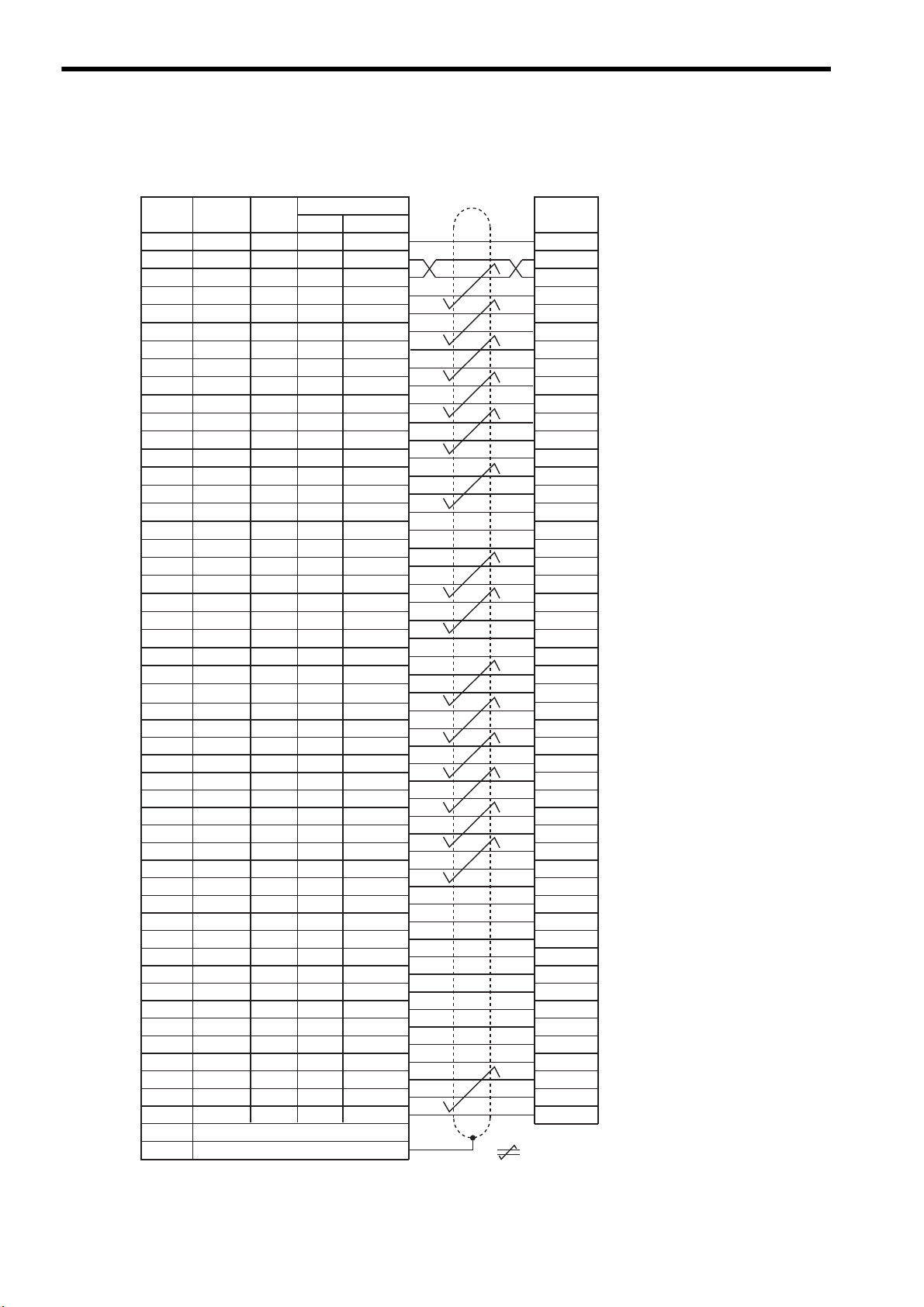
5 Specifications and Dimensional Drawings of Cables and Peripheral Devices
SG
SG
PL1
SEN
V-REF
SG
PULS
/PULS
T-REF
SG
SIGN
/SIGN
PL2
/CLR
CLR
−
−
PL3
PCO
/PCO
BAT(+)
BAT(-)
−
−
/V-CMP+
/V-CMP-
/TGON+
/TGON-
/S-RDY+
/S-RDY-
ALM+
ALM-
PAO
/PAO
PBO
/PBO
ALO1
ALO2
ALO3
/S-ON
/P-CON
P-OT
N-OT
/ALM-RST
/P-CL
/N-CL
+24VIN
PSO
/PSO
−
Host controller end
Pin No.
Lead
Color
Signal
Marking
Color
1
2
3
4
5
6
7
8
9
10
11
12
13
14
15
16
17
18
19
20
21
22
23
24
25
26
Lead
Marker No.
1
2
3
4
5
6
7
8
9
10
11
12
13
14
15
16
17
18
19
20
21
22
23
24
25
26
Orange
Gray
Orange
Gray
White
White
Yellow
Yellow
Pink
Pink
Orange
Orange
Gray
White
White
Gray
Yellow
Yellow
Pink
Pink
Orange
Orange
Gray
Gray
White
White
Red
Red
Black
Black
Red
Black
Red
Black
Red
Black
Red
Black
Red
Red
Black
Black
Red
Black
Red
Black
Red
Black
Red
Black
Red
Black
1
1
1
1
1
1
1
1
1
1
2
2
2
2
2
2
2
2
2
2
3
3
3
3
3
3
SERVOPACK end
27
28
29
30
31
32
33
34
35
36
37
38
39
40
41
42
43
44
45
46
47
48
49
50
Case
27
28
29
30
31
32
33
34
35
36
37
38
39
40
41
42
43
44
45
46
47
48
49
50
Yellow
Yellow
Pink
Pink
Orange
Orange
Gray
Gray
White
White
Yellow
Yellow
Pink
Pink
Orange
Orange
Gray
Gray
White
White
Yellow
Pink
Pink
Yellow
Red
Black
Red
Black
Red
Black
Red
Black
Red
Black
Red
Black
Red
Black
Red
Black
Red
Black
Red
Black
Red
Red
Black
Black
3
3
3
3
4
4
4
4
4
4
4
4
4
4
5
5
5
5
5
5
5
5
5
5
Shield
represents twisted-pair wires.
Dots
5.4.3 Connection Diagram
5.4.3 Connection Diagram
5-12
Page 94

5
Specifications and Dimensional Drawings of Cables and Peripheral Devices
5.5 Peripheral Devices
Personal computer end
Signal Pin No.
Case
SERVOPACK end
SignalPin No.
14
−
0 V
−
−−
RXD
TXD
0 V
RTS
CTS
FG
3
2
7
4
5
1
/TXD
/RXD
FG
2
4
Shield wire
38 39
61
95
81
14 7
2
× M2.6 screws
2
× M2.6 screws
2000
±50
Half-pitch connector
Plug: 10114-3000VE
Shell: 10314-52A0-008
(Sumitomo 3M Ltd.)
D-sub connector (9-pin)
17JE1309002㧔D8A㧕
(DDK Ltd.)
32
29.5
Personal computer end
SERVOPACK end
Cable type:
AWG26
×
3C UL2464
Units: mm
Personal computer end
Signal Pin No.
Case
SERVOPACK end
SignalPin No.
14
−
0 V
−
−−
RXD
TXD
0 V
RTS
CTS
FG
2
3
5
7
8
Case
/TXD
/RXD
FG
2
4
Shield wire
Label
81
14
7
81
14 7
2
× M2.6 screws
5
39
Half-pitch connector
Plug: 101143000VE
Shell: 1031452A0008
(Sumitomo 3M Ltd.)
Half-pitch connector
Plug: 101143000VE
Shell: 1031452F0008
(Sumitomo 3M Ltd.)
39
29.5
Personal computer end
SERVOPACK end
Cable:
AWG26
×
3C UL2464
2000±50
29.5
Units: mm
Personal computer end
Signal Pin No.
Case
SERVOPACK end
SignalPin No.
14
−
0 V
−
−−
RXD
TXD
RTS
CTS
GND
FG
FG
1
9
10
4
14
12
Case
/TXD
/RXD
FG
2
4
Shield wire
5.5.1 Cables for Connecting Personal Computers
(1) For 25-pin Connector Cable for NEC PC-98 Series PC
(a) Cable Type: JZSP-CMS01
(b) Dimensional Drawing
5.5 Peripheral Devices
Personal computer end
D-sub connector (25-pin)
17JE-23250-02㧔D8A㧕
(DDK Ltd.)
114
47
25 13
38
Cable type:
AWG263C UL2464
2M2.6 screws
Half-pitch connector
Plug: 10114-3000VE
Shell: 10314-52A0-008
(Sumitomo 3M Ltd.)
2000±50
M2.6 screws
2
SERVOPACK end
39
8
14
Units: mm
1
7
(2) D-sub, 9-pin Connector Cable for IBM PC Compatible
(a) Cable Type: JZSP-CMS02
(b) Dimensional Drawing
(3) 14-pin Half-pitch Connector Cable for NEC PC-98 Series PC
(a) Cable Type: JZSP-CMS03
(b) Dimensional Drawing
5-13
Page 95

5 Specifications and Dimensional Drawings of Cables and Peripheral Devices
Digital Operator
.4 .5
.6
789
8
8
&7
88
8
&9&8 $
8
&%
0
$
&%
2
%*#4)'
5*&)
㧖㧖㧖㧖
6 #5''/1&
-5'4812#%
#;#5-#9
4
1
2
'
4
#
6
1
%0
%0
219'4
%0
WARNING
ෂޓ㒾
ㅢ㔚߮㔚Ḯࠝࡈᓟ5
ಽ㑆ޔ┵ሶㇱߦ⸅ࠆߥ
electric shock.
Disconnect all power
May cause
ᗵ㔚ߩᕟࠇࠅ
before servicing.
and wait 5 min.
grounding techniques.
ធ⛯ߖࠃ
Use proper
ᔅߕࠕ㧙ࠬ✢ࠍ
2 × φ4.5 mounting holes
125
135
63
Units: mm
18.5
7
50
YASKAWA
26
(8)
39
29.5
L
2101
9
8111
7
Digital Operator end
Units: mm
SERVOPACK end
17.3
29.5
20.2
30
39
5.5.2 Digital Operator
5.5.2 Digital Operator
(1) Model JUSP-OP02A-2 with a 1m-connection Cable
(2) Dimensional Drawing
(3) Other Types of the Applicable Connection Cables: JZSP-CMS00-
5-14
* Order your cable from Yaskawa Controls Co., Ltd. in the following cases.
• When you need a longer cable than the cable supplied with the digital operator.
• When you need additional cables.
Cable Type Cable Length
JZSP-CMS00-1
JZSP-CMS00-2
JZSP-CMS00-3
(L)
1 m
1.5 m
2 m
Page 96

5
Specifications and Dimensional Drawings of Cables and Peripheral Devices
5.5.3 Cables for Analog Monitor
Cable for Analog Monitor
.4 .5
.6
789
8
8
&7
88
8
&9&8 $
8
&%
0
$
&%
2
%*#4)'
5*&)
㧖㧖㧖㧖
6 #5''/1&
-5'4812#%
#;#5-#9
4
1
2
'
4
#
6
1
%0
%0
219'4
%0
WARNING
ෂޓ㒾
ㅢ㔚߮㔚Ḯࠝࡈᓟ5
ಽ㑆ޔ┵ሶㇱߦ⸅ࠆߥ
electric shock.
Disconnect all power
May cause
ᗵ㔚ߩᕟࠇࠅ
before servicing.
and wait 5 min.
grounding techniques.
ធ⛯ߖࠃ
Use proper
ᔅߕࠕ㧙ࠬ✢ࠍ
3
4
1
2
Socket: DF11-4DS-2C
∗
Connector: DF11-2428SCF
∗
1000 ޓmm
-0
+20
White
Red
Black
Black
Viewed from the cable
(1) Cable Type: JZSP-CA01 (DE9404559)
Connect the specified cables to CN5 connector for monitoring the analog monitor signals. For details, refer to
9.5 Analog Monitor.
Note: Specify the cable type either JZSP-CA01 or DE9404559 when ordering the cable for analog moni-
tor.
(2) Dimensional Drawing
5.5 Peripheral Devices
* Manufactured by Hirose Electric Corporation.
(3) Specifications
Pin No. Cable Color Signal Monitoring Item
1
2
3 and 4
Red
White
Black (2 cables)
Analog Monitor 2
Motor speed: 1V/1000 min
Analog Monitor 1 Torque reference: 1V/100% rated torque
GND (0 V) −
Note: The above monitoring items are the factory settings. The monitoring items can be changed by set-
ting the parameter Pn003. Refer to 9.5 Analog Monitor.
-1
5-15
Page 97

5 Specifications and Dimensional Drawings of Cables and Peripheral Devices
1
19
33
16
32
50
1
1
2
49
50
SERVOPACK
Connector terminal block converter unit
model: JUSP-TA50PG
CN1
Attached cable length: 500
mm
+50
-0
.4 .5
.6
789
8
8
&7
88
8
&9&8 $
8
&%
0
$
&%
2
%*#4)'
5*&)
㧖㧖㧖㧖
6 #5''/1&
-5'4812#%
#;#5-#9
4
1
2
'
4
#
6
1
%0
%0
219'4
%0
WARNING
ෂޓ㒾
ㅢ㔚߮㔚Ḯࠝࡈᓟ5
ಽ㑆ޔ┵ሶㇱߦ⸅ࠆߥ
electric shock.
Disconnect all power
May cause
ᗵ㔚ߩᕟࠇࠅ
before servicing.
and wait 5 min.
grounding techniques.
ធ⛯ߖࠃ
Use proper
ᔅߕࠕ㧙ࠬ✢ࠍ
1
19
33
16
32
50
1
1
2
49
50
Terminal
block (50P)
M3.5 screw
Connector plug (50P)
MR-50RMD2
7
7
15.5
45
15.5
45
3.53.5
29.5
29.5
2×φ3.5
247.5 3.5
3.5
2×M3 screw holes
247.5
2
20.5
43.5
Can be fixed on DIN rail
(62)
Units: mm
With terminal block
cover removed
500
SERVOPACK end connector (50P)
10150-6000EL (Sumitomo 3M Ltd.)
Shell
10350-52AO-008 (Sumitomo 3M Ltd.)
Cable (black)
AWG#2825P
UL20276 VW-1SC
Connector terminal block converter unit
end connector (50P)
MRP-50F01 (Honda Tsushin Kogyo Co., Ltd.)
Case
MR-50L
(Honda Tsushin Kogyo Co., Ltd.)
+50
0
Units: mm
5.5.4 Connector Terminal Block Converter Unit
5.5.4 Connector Terminal Block Converter Unit
(1) Model: JUSP-TA50PG
The connection between the connector terminal block converter and the SERVOPACK is shown below.
(2) Dimensional Drawings of Terminal Block
(3) Dimensional Drawing of Cable
5-16
Page 98

5
Specifications and Dimensional Drawings of Cables and Peripheral Devices
5.5.5 Brake Power Supply Unit
Yellow
White
Red
Black
AC side
180 to 230 V
Diode
Surge absorber
DC (Brake) side
No polarity
Surge absorber
(1) Model: LPSE-2H01, LPDE-1H01
Contact Yaskawa Controls Co., Ltd.
• 200 V input: LPSE-2H01
• 100 V input: LPDE-1H01
(2) Specifications
• Rated output voltage: 90 VDC
• Maximum output current: 1.0 ADC
• Lead wire length: 500 mm each
• Maximum surrounding air temperature: 60°C
• Lead wires: Color coded. Refer to the table below.
AC Input End Brake End
100 V 200 V
Blue/White Yellow/White Red/Blue
(3) Dimensional Drawing
5.5 Peripheral Devices
50
30
2 Mounting holes φ3
(Spot facing φ5.5
and 4 long㧕
Nameplate
Lead wire
25
11
20
Units: mm
(4) Internal Circuits
The brake power supply circuit can be opened and closed either on AC or DC side. However, if the wiring distance on DC side is too long, the brake circuit may not operate normally due to the influence of switching noises.
When switching the circuit on AC side, install a surge absorber model CR50500BL (sold as spark quencher) for
the brake power supply near the brake coil to reduce the influence of switching noises.
When switching the circuit on DC side, the influence of the switching noise is minimal, even without installing a
surge absorber. However, the surge voltage at switching may damage the brake coil. Install a surge absorber
near the brake coil to prevent the damage to the brake coil in addition to the built-in surge absorber.
(a) Internal Circuit for 200 VAC
Brake Power Supply Model: LPSE-2H01
5-17
Page 99

5 Specifications and Dimensional Drawings of Cables and Peripheral Devices
Blue
White
Red
Black
AC side
90 to 120 V
Diode bridge
Surge
absorber
Surge
absorber
DC (Brake) side
No polarity
PROHIBITED
ޓRed
Connector
2ޓBlack
㧗
26
17
14.5
50±5
Lithium battery ER3V
3.6 V 1000 mAh
Manufactured by Toshiba Battery Co., Ltd.
Units: mm
5.5.6 Absolute Encoder Battery
(b) Internal Circuit for 100 VAC
Brake Power Supply Model: LPDE-1H01
Brake Power Supply Unit for the 24 VDC
The brake power supply unit for the 24 VDC is not provided by Yaskawa. When using the servomotor with a 24-VDC
brake, the brake power supply unit is to be provided by the customer.
5.5.6 Absolute Encoder Battery
When using an absolute encoder, a backup battery is required to prevent the position data from being lost at
power OFF. Install one of the following absolute encoder batteries.
There are two types of battery: Battery to be mounted on the SERVOPACK and battery to be connected to the
host controller.
• Install the absolute encoder battery on either the SERVOPACK or the host controller.
Installing the batteries both on the SERVOPACK and host controller configures a loop in the circuit between two batteries, which damages the circuit.
(1) Battery Mounted on SERVOPACK
(a) Model
JZSP-BA01-1
(b) Dimensional Drawing
(2) Battery Connected to the Host Controller
When connecting the battery to the host controller, select the battery in accordance with the specifications of the
host controller.
Use the battery ER6 VC3 or the equivalent:
3.6 V, 2000 mAh manufactured by Toshiba Battery Co., Ltd.
5-18
Page 100

5
Specifications and Dimensional Drawings of Cables and Peripheral Devices
5.5.7 Molded-case Circuit Breaker (MCCB)
IMPORTANT
If selecting a molded-case circuit breaker, observe the following precautions.
Circuit Breakers
• Select a breaker for inverters.
• High-frequency current leaks from the servomotor armature because of switching operations inside the
SERVOPACK.
(1) Maximum Input Current
• The instantaneous maximum output of SERVOPACK is 3 times of the rated output for maximum 3 seconds. Accordingly, select a circuit breaker whose operating time is 5 seconds or more at 300% of SERVOPACK rated current.
The general-purpose and low-speed acting molded-case circuit breakers are applicable.
• The power supply capacity per SERVOPACK when using a servomotor is described in 2.6.2 Molded-case
Circuit Breaker and Fuse Capacity. Select a circuit breaker with the capacity larger than the effective
load current (when using multiple SERVOPACKs) calculated from the total power supply capacity.
• The power consumption of other controllers must be considered when selecting a circuit breaker.
5.5 Peripheral Devices
(2) Inrush Current
• Refer to 2.6.2 Molded-case Circuit Breaker and Fuse Capacity for SERVOPACK inrush current.
• The allowable inrush current for a low-speed acting circuit breaker is approximately 10 times of the rated
current for 0.02 seconds.
• When turning ON multiple SERVOPACKs simultaneously, select a molded-case circuit breaker with the
allowable current for 20 ms larger than the total inrush current shown in 2.6.2 Molded-case Circuit
Breaker and Fuse Capacity.
5-19
 Loading...