

Page 1

AC Servo Drives
-V Series
USER’S MANUAL
Design and Maintenance
Rotational Motor
MECHATROLINK-III Communications Reference
SGDV SERVOPACK
SGMJV/SGMAV/SGMPS/SGMGV/SGMSV/SGMCS Servomotors
MANUAL NO. SIEP S800000 64H
Outline
Panel Display and
Operation of Digital Operator
Wiring and Connection
Operation
Adjustments
Utility Functions (Fn)
Monitor Displays (Un)
Fully-closed Loop Control
Troubleshooting
Appendix
1
2
3
4
5
6
7
8
9
10
Page 2

Copyright © 2008 YASKAWA ELECTRIC CORPORATION
All rights reserved. No part of this publication may be reproduced, stored in a retrieval system,
or transmitted, in any form, or by any means, mechanical, electronic, photocopying, recording,
or otherwise, without the prior written permission of Yaskawa. No patent liability is assumed
with respect to the use of the information contained herein. Moreover, because Yaskawa is constantly striving to improve its high-quality products, the information contained in this manual is
subject to change without notice. Every precaution has been taken in the preparation of this
manual. Nevertheless, Yaskawa assumes no responsibility for errors or omissions. Neither is
any liability assumed for damages resulting from the use of the information contained in this
publication.
Page 3
About this Manual
This manual describes information required for designing, testing, adjusting, and maintaining Σ-V Series
SERVOPACKs.
Keep this manual in a location where it can be accessed for reference whenever required. Manuals outlined on
the following page must also be used as required by the application.
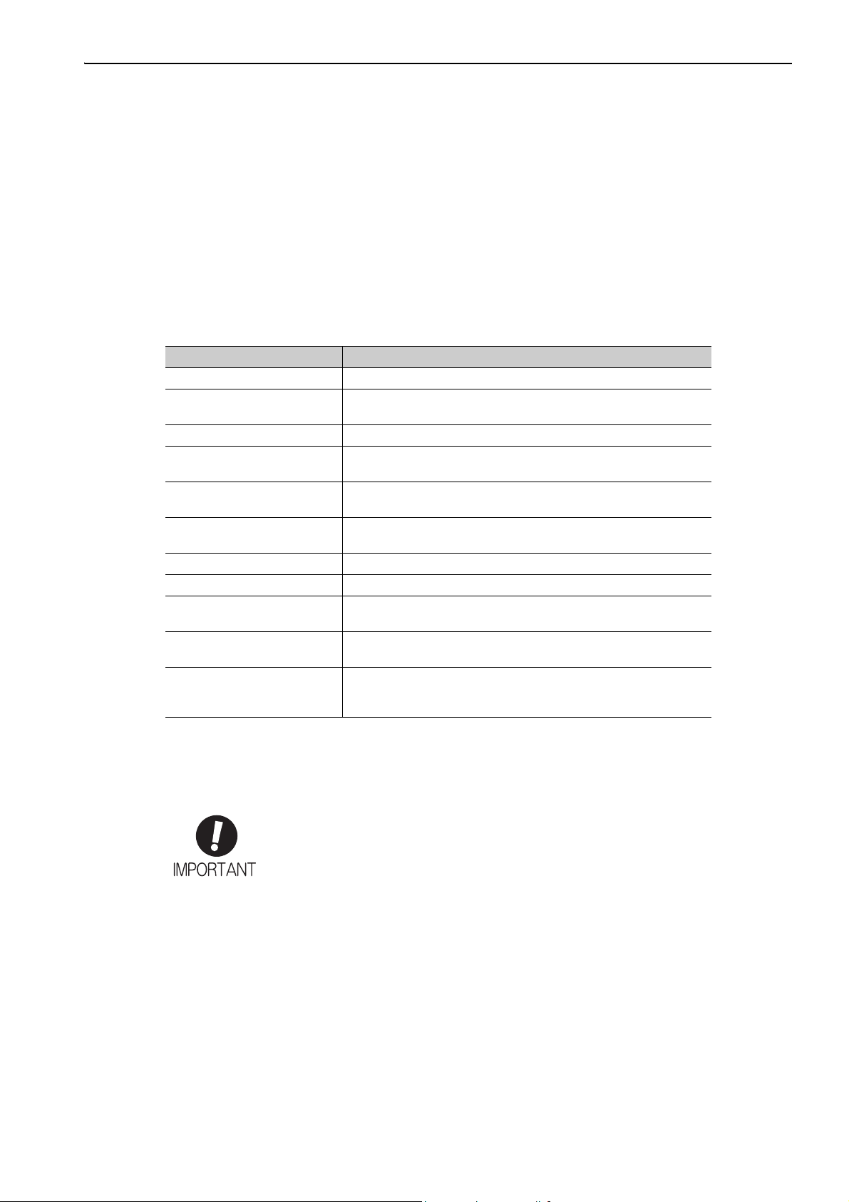
Description of Technical Terms
The following table shows the meanings of terms used in this manual.
Te rm Meaning
Cursor Input position indicated by Digital Operator
Servomotor
SERVOPACK Σ-V Series SGDV servo amplifier
Servo Drive
Servo System
M-III Model
Servo ON Power to motor ON
Servo OFF Power to motor OFF
Base Block (BB)
Servo Lock
Main Circuit Cable
Σ-V Series SGMJV, SGMAV, SGMPS, SGMGV, SGMSV, or SGMCS
(Direct Drive) servomotor
A set including a servomotor and SERVOPACK (i.e., a servo amplifier)
A servo control system that includes the combination of a servo drive
with a host controller and peripheral devices
MECHATROLINK-III communications reference used for SERVOPACK interface
Power supply to motor is turned OFF by shutting off the base current
to the power transistor in the current amplifier.
A state in which the motor is stopped and is in position loop with a
position reference of 0.
Cables which connect to the main circuit terminals, including main
circuit power supply cables, control power supply cables, servomotor
main circuit cables, and others.
IMPORTANT Explanations
The following icon is displayed for explanations requiring special attention.
• Indicates important information that should be memorized, as well as precautions, such as
alarm displays, that do not involve potential damage to equipment.
iii
Page 4
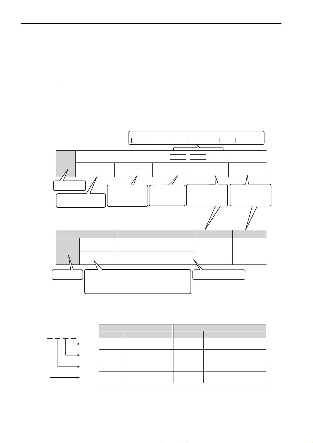
Pn406
Emergency Stop Torque
Setting Range
0% to 800% 1% 800 After change
Setting Unit Factory Setting When Enabled
Classification
Setup
Parameter Meaning When Enabled Classification
Pn002
After restart
n.0
[Factory setting]
n.1
Uses the absolute encoder as an
incremental encoder.
Uses the absolute encoder as an
absolute encoder.
Setup
Parameter
number
Parameter
number
Position
Torque
Control methods for which the parameter applies.
Speed
: Speed control
: Position control
: Torque control
Indicates the
parameter setting
before shipment.
Indicates when a
change to the
parameter will be
effective.
Indicates the
parameter
classification.
Indicates the
minimum setting unit
for the parameter.
Torque
Position Speed
Indicates the setting
range for the parameter.
The notation “n.” indicates a parameter
for selecting functions. Each corresponds to
the setting value of that digit. The notation shown
here means that the third digit is 1.
This section explains the
selections for the function.
• Parameters for Selecting Functions
Rotation
1st digit
2nd digit
3rd digit
4th digit
Digital Operator Display
(Display Example for Pn002)
Digit Notation Setting Notation
Meaning Notation Meaning
Pn002.0
Pn002.1
Pn002.2
Pn002.3
Indicates the value for the
1st digit of parameter Pn002.
Indicates the value for the
2nd digit of parameter Pn002.
Indicates the value for the
3rd digit of parameter Pn002.
Indicates the value for the
4th digit of parameter Pn002.
Pn002.0 = x
or n.x
Pn002.1 = x
or n.x
Indicates that the value for the
1st digit of parameter Pn002 is x.
Indicates that the value for the
2nd digit of parameter Pn002 is x.
Pn002.2 = x
or n.x
Pn002.3 = x
or n.x
Indicates that the value for the
3rd digit of parameter Pn002 is x.
Indicates that the value for the
4th digit of parameter Pn002 is x.
Notation
MECHA
Notation Used in this Manual
• Notation for Reverse Signals
The names of reverse signals (i.e., ones that are valid when low) are written with a forward slash (/) before the
signal name.
Notation Example
BK
= /BK
• Notation for Parameters
The notation depends on whether the parameter requires a value setting (parameter for numeric settings) or
requires the selection of a function (parameter for selecting functions).
• Parameters for Numeric Settings
iv
Notation Example
Page 5

Manuals Related to the Σ-V Series
Refer to the following manuals as required.
Name
Σ-V Series
User's Manual
Setup
Rotational Motor
(No.: SIEP S800000 43)
Σ-V Series
Product Catalog
(No.: KAEP S800000 42)
Σ-V Series
User's Manual
Design and Maintenance
Rotational Motor/
MECHATROLINK-III
Communications Reference
(this manual)
Σ-V Series
User’s Manual
MECHATROLINK-III
Standard Servo Profile
Commands
(No.: SIEP S800000 63)
Σ-V Series
User’s Manual
Operation of Digital Operator
(No.: SIEP S800000 55)
Σ-V Series
AC SERVOPACK SGDV
Safety Precautions
(No.: TOBP C710800 10)
Σ Series
Digital Operator
Safety Precautions
(No.: TOBP C730800 00)
AC SERVOMOTOR
Safety Precautions
(No.: TOBP C230200 00)
Selecting
Models and
Peripheral
Devices
Ratings and
Specifications
System
Design
Panels and
Wiring
Trial
Operation
Trial
Operation
and Servo
Adjustment
Maintenance
and
Inspection
Trademarks
MECHATROLINK is a trademark of the MECHATROLINK Members Association.
v
Page 6
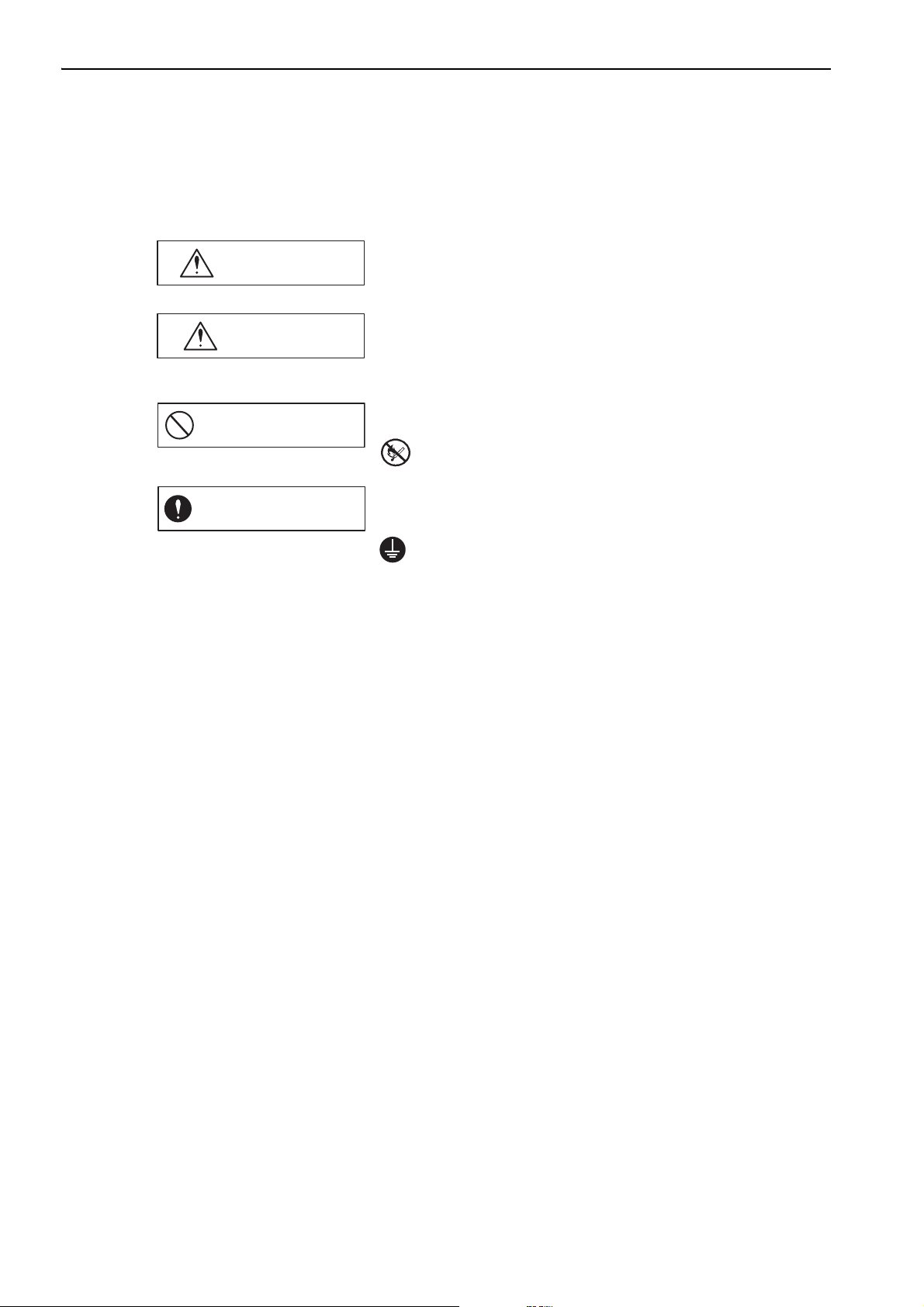
WARNING
CAUTION
PROHIBITED
MANDATORY
Safety Information
The following conventions are used to indicate precautions in this manual. Failure to heed precautions provided in this manual can result in serious or possibly even fatal injury or damage to the products or to related
equipment and systems.
Indicates precautions that, if not heeded, could possibly result in loss of
life or serious injury.
Indicates precautions that, if not heeded, could result in relatively serious
or minor injury, damage to the product, or faulty operation.
In some situations, the precautions indicated could have serious
consequences if not heeded.
Indicates prohibited actions that must not be performed. For example,
this symbol would be used to indicate that fire is prohibited as follows:
Indicates compulsory actions that must be performed. For example, this
symbol would be used to indicate that grounding is compulsory as
follows:
vi
Page 7
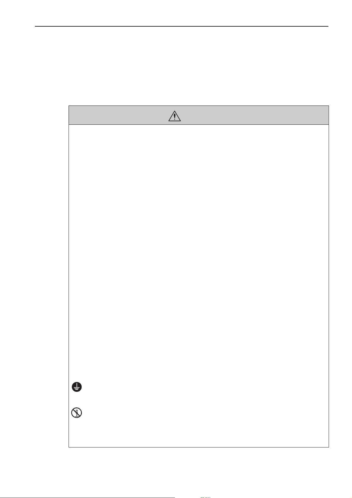
Safety Precautions
This section describes important precautions that must be followed during storage, transportation, installation,
wiring, operation, maintenance, inspection, and disposal. Be sure to always observe these precautions thoroughly.
• Never touch any rotating servomotor parts during operation.
Failure to observe this warning may result in injury.
• Before starting operation with a machine connected, make sure that an emergency stop can be
applied at any time.
Failure to observe this warning may result in injury or damage to the equipment.
• Never touch the inside of the SERVOPACKs.
Failure to observe this warning may result in electric shock.
• Do not remove the cover of the power supply terminal block while the power is ON.
Failure to observe this warning may result in electric shock.
• After the power is turned OFF or after a voltage resistance test, do not touch terminals while the
CHARGE lamp is ON.
Residual voltage may cause electric shock.
• Follow the procedures and instructions provided in the manuals for the products being used in the
trial operation.
Failure to do so may result not only in faulty operation and damage to equipment, but also in personal injury.
• The output range of the rotational serial data for the Σ-V absolute position detecting system is different from that of earlier systems for 12-bit and 15-bit encoders. As a result, the infinite-length positioning system of the Σ Series must be changed for use with products in the Σ-V Series.
• The multiturn limit value need not be changed except for special applications.
Changing it inappropriately or unintentionally can be dangerous.
• If the Multiturn Limit Disagreement alarm occurs, check the setting of parameter Pn205 in the SERVOPACK to be sure that it is correct.
If Fn013 is executed when an incorrect value is set in Pn205, an incorrect value will be set in the encoder. The
alarm will disappear even if an incorrect value is set, but incorrect positions will be detected, resulting in a
dangerous situation where the machine will move to unexpected positions.
• Do not remove the top front cover, cables, connectors, or optional items from the SERVOPACK
while the power is ON.
Failure to observe this warning may result in electric shock.
• Do not damage, pull, exert excessive force on, or place heavy objects on the cables.
Failure to observe this warning may result in electric shock, stopping operation of the product, or fire.
• Do not modify the product.
Failure to observe this warning may result in injury, damage to the equipment, or fire.
• Provide appropriate braking devices on the machine side to ensure safety. The holding brake on a
servomotor with a brake is not a braking device for ensuring safety.
Failure to observe this warning may result in injury.
• Do not come close to the machine immediately after resetting an instantaneous power interruption
to avoid an unexpected restart. Take appropriate measures to ensure safety against an unexpected
restart.
Failure to observe this warning may result in injury.
• Connect the ground terminal according to local electrical codes (100 Ω or less for a SERVOPACK
with a 100 V, 200 V power supply, 10 Ω or less for a SERVOPACK with a 400 V power supply).
Improper grounding may result in electric shock or fire.
WARNING
• Installation, disassembly, or repair must be performed only by authorized personnel.
Failure to observe this warning may result in electric shock or injury.
• The person who designs a system using the safety function (Hard Wire Baseblock function) must
have full knowledge of the related safety standards and full understanding of the instructions in this
manual.
Failure to observe this warning may result in injury or damage to the equipment.
vii
Page 8
Storage and Transportation
CAUTION
• Do not store or install the product in the following locations.
Failure to observe this caution may result in fire, electric shock, or damage to the equipment.
• Locations subject to direct sunlight
• Locations subject to temperatures outside the range specified in the storage/installation temperature conditions
• Locations subject to humidity outside the range specified in the storage/installation humidity conditions
• Locations subject to condensation as the result of extreme changes in temperature
• Locations subject to corrosive or flammable gases
• Locations subject to dust, salts, or iron dust
• Locations subject to exposure to water, oil, or chemicals
• Locations subject to shock or vibration
• Do not hold the product by the cables, motor shaft, or encoder while transporting it.
Failure to observe this caution may result in injury or malfunction.
• Do not place any load exceeding the limit specified on the packing box.
Failure to observe this caution may result in injury or malfunction.
• If disinfectants or insecticides must be used to treat packing materials such as wooden frames, pallets, or plywood, the packing materials must be treated before the product is packaged, and methods other than fumigation must be used.
Example: Heat treatment, where materials are kiln-dried to a core temperature of 56
minutes or more.
If the electronic products, which include stand-alone products and products installed in machines, are packed
with fumigated wooden materials, the electrical components may be greatly damaged by the gases or fumes
resulting from the fumigation process. In particular, disinfectants containing halogen, which includes chlorine, fluorine, bromine, or iodine can contribute to the erosion of the capacitors.
°C for 30
Installation
• Never use the product in an environment subject to water, corrosive gases, flammable gases, or
combustibles.
Failure to observe this caution may result in electric shock or fire.
• Do not step on or place a heavy object on the product.
Failure to observe this caution may result in injury or malfunction.
• Do not cover the inlet or outlet ports and prevent any foreign objects from entering the product.
Failure to observe this caution may cause internal elements to deteriorate resulting in malfunction or fire.
• Be sure to install the product in the correct direction.
Failure to observe this caution may result in malfunction.
• Provide the specified clearances between the SERVOPACK and the control panel or with other
devices.
Failure to observe this caution may result in fire or malfunction.
• Do not apply any strong impact.
Failure to observe this caution may result in malfunction.
CAUTION
viii
Page 9

Wiring
CAUTION
• Be sure to wire correctly and securely.
Failure to observe this caution may result in motor overrun, injury, or malfunction.
• Do not connect a commercial power supply to the U, V, or W terminals for the servomotor connection.
Failure to observe this caution may result in injury or fire.
• Securely connect the main circuit terminals.
Failure to observe this caution may result in fire.
• Do not bundle or run the main circuit cables together with the I/O signal cables or the encoder
cables in the same duct. Keep the main circuit cables separated from the I/O signal cables and the
encoder cables with a gap of at least 30 cm.
Placing these cables too close to each other may result in malfunction.
• Use shielded twisted-pair cables or screened unshielded twisted-pair cables for I/O signal cables
and the encoder cables.
• The maximum wiring length is 3 m for I/O signal cables, 50 m for encoder cables or servomotor
main circuit cables, and 10 m for control power supply cables for the SERVOPACK with a 400-V
power supply (+24 V, 0 V).
• Do not touch the power supply terminals while the CHARGE lamp is ON after turning power OFF
because high voltage may still remain in the SERVOPACK.
Make sure the charge indicator is OFF first before starting to do wiring or inspections.
• Be sure to observe the following precautions when wiring the SERVOPACK main circuit terminal
blocks.
• Do not turn the SERVOPACK power ON until all wiring, including the main circuit terminal blocks, has
been completed.
• Remove detachable main circuit terminals from the SERVOPACK prior to wiring.
• Insert only one power line per opening in the main circuit terminals.
• Make sure that no part of the core wire comes into contact with (i.e., short-circuits) adjacent wires.
• Install a battery at either the host controller or the SERVOPACK, but not both.
It is dangerous to install batteries at both ends simultaneously, because that sets up a loop circuit between the
batteries.
• Always use the specified power supply voltage.
An incorrect voltage may result in fire or malfunction.
• Make sure that the polarity is correct.
Incorrect polarity may cause ruptures or damage.
• Take appropriate measures to ensure that the input power supply is supplied within the specified
voltage fluctuation range. Be particularly careful in places where the power supply is unstable.
An incorrect power supply may result in damage to the equipment.
• Install external breakers or other safety devices against short-circuiting in external wiring.
Failure to observe this caution may result in fire.
• Take appropriate and sufficient countermeasures for each form of potential interference when
installing systems in the following locations.
• Locations subject to static electricity or other forms of noise
• Locations subject to strong electromagnetic fields and magnetic fields
• Locations subject to possible exposure to radioactivity
• Locations close to power supplies
Failure to observe this caution may result in damage to the equipment.
• Do not reverse the polarity of the battery when connecting it.
Failure to observe this caution may damage the battery, the SERVOPACK or servomotor, or cause an explosion.
• Wiring or inspection must be performed by a technical expert.
• Use a 24-VDC power supply with double insulation or reinforced insulation.
ix
Page 10
Operation
CAUTION
• Always use the servomotor and SERVOPACK in one of the specified combinations.
Failure to observe this caution may result in fire or malfunction.
• Conduct trial operation on the servomotor alone with the motor shaft disconnected from the
machine to avoid accidents.
Failure to observe this caution may result in injury.
• During trial operation, confirm that the holding brake works correctly. Furthermore, secure system
safety against problems such as signal line disconnection.
• Before starting operation with a machine connected, change the parameter settings to match the
parameters of the machine.
Starting operation without matching the proper settings may cause the machine to run out of control or malfunction.
• Do not turn the power ON and OFF more than necessary.
Do not use the SERVOPACK for applications that require the power to turn ON and OFF frequently. Such
applications will cause elements in the SERVOPACK to deteriorate.
As a guideline, at least one hour should be allowed between the power being turned ON and OFF once actual
operation has been started.
• When carrying out JOG operation (Fn002), origin search (Fn003), or EasyFFT (Fn206), forcing
movable machine parts to stop does not work for forward overtravel or reverse overtravel. Take
necessary precautions.
Failure to observe this caution may result in damage to the equipment.
• When using the servomotor for a vertical axis, install safety devices to prevent workpieces from falling due to alarms or overtravels. Set the servomotor so that it will stop in the zero clamp state when
overtravel occurs.
Failure to observe this caution may cause workpieces to fall due to overtravel.
• When not using the turning-less function, set the correct moment of inertia ratio (Pn103).
Setting an incorrect moment of inertia ratio may cause machine vibration.
• Do not touch the SERVOPACK heat sinks, regenerative resistor, or servomotor while power is ON
or soon after the power is turned OFF.
Failure to observe this caution may result in burns due to high temperatures.
• Do not make any extreme adjustments or setting changes of parameters.
Failure to observe this caution may result in injury or damage to the equipment due to unstable operation.
• When an alarm occurs, remove the cause, reset the alarm after confirming safety, and then resume
operation.
Failure to observe this caution may result in damage to the equipment, fire, or injury.
• Do not use the holding brake of the servomotor for braking.
Failure to observe this caution may result in malfunction.
• An alarm or warning may occur if communications are performed with the host controller while the
SigmaWin+ or Digital Operator is operating.
If an alarm or warning occurs, it may stop the current process and stop the system.
Maintenance and Inspection
CAUTION
• Do not disassemble the SERVOPACK and the servomotor.
Failure to observe this caution may result in electric shock or injury.
• Do not attempt to change wiring while the power is ON.
Failure to observe this caution may result in electric shock or injury.
• When replacing the SERVOPACK, resume operation only after copying the previous SERVOPACK
parameters to the new SERVOPACK.
Failure to observe this caution may result in damage to the equipment.
Disposal
CAUTION
• When disposing of the products, treat them as ordinary industrial waste.
x
Page 11

General Precautions
Observe the following general precautions
• The products shown in illustrations in this manual are sometimes shown without covers or protective guards.
Always replace the cover or protective guard as specified first, and then operate the products in accordance with
the manual.
• The drawings presented in this manual are typical examples and may not match the product you received.
• If the manual must be ordered due to loss or damage, inform your nearest Yaskawa representative or one of the
offices listed on the back of this manual.
to ensure safe application.
xi
Page 12

Warranty
(1) Details of Warranty
Warranty Period
Warranty Scope
(2) Limitations of Liability
The warranty period for a product that was purchased (hereinafter called “delivered product”) is one year from
the time of delivery to the location specified by the customer or 18 months from the time of shipment from the
Yaskawa factory, whichever is sooner.
Yaskawa shall replace or repair a defective product free of charge if a defect attributable to Yaskawa occurs
during the warranty period above. This warranty does not cover defects caused by the delivered product reaching the end of its service life and replacement of parts that require replacement or that have a limited service
life.
This warranty does not cover failures that result from any of the following causes.
1. Improper handling, abuse, or use in unsuitable conditions or in environments not described in product catalogs or manuals, or in any separately agreed-upon specifications
2. Causes not attributable to the delivered product itself
3. Modifications or repairs not performed by Yaskawa
4. Abuse of the delivered product in a manner in which it was not originally intended
5. Causes that were not foreseeable with the scientific and technological understanding at the time of shipment from Yaskawa
6. Events for which Yaskawa is not responsible, such as natural or human-made disasters
1. Yaskawa shall in no event be responsible for any damage or loss of opportunity to the customer that arises
due to failure of the delivered product.
2. Yaskawa shall not be responsible for any programs (including parameter settings) or the results of program
execution of the programs provided by the user or by a third party for use with programmable Yaskawa
products.
3. The information described in product catalogs or manuals is provided for the purpose of the customer purchasing the appropriate product for the intended application. The use thereof does not guarantee that there
are no infringements of intellectual property rights or other proprietary rights of Yaskawa or third parties,
nor does it construe a license.
4. Yaskawa shall not be responsible for any damage arising from infringements of intellectual property rights
or other proprietary rights of third parties as a result of using the information described in catalogs or manuals.
xii
Page 13

(3) Suitability for Use
1. It is the customer’s responsibility to confirm conformity with any standards, codes, or regulations that
apply if the Yaskawa product is used in combination with any other products.
2. The customer must confirm that the Yaskawa product is suitable for the systems, machines, and equipment
used by the customer.
3. Consult with Yaskawa to determine whether use in the following applications is acceptable. If use in the
application is acceptable, use the product with extra allowance in ratings and specifications, and provide
safety measures to minimize hazards in the event of failure.
• Outdoor use, use involving potential chemical contamination or electrical interference, or use in conditions or environments not described in product catalogs or manuals
• Nuclear energy control systems, combustion systems, railroad systems, aviation systems, vehicle systems, medical equipment, amusement machines, and installations subject to separate industry or government regulations
• Systems, machines, and equipment that may present a risk to life or property
• Systems that require a high degree of reliability, such as systems that supply gas, water, or electricity, or
systems that operate continuously 24 hours a day
• Other systems that require a similar high degree of safety
4. Never use the product for an application involving serious risk to life or property without first ensuring that
the system is designed to secure the required level of safety with risk warnings and redundancy, and that the
Yaskawa product is properly rated and installed.
5. The circuit examples and other application examples described in product catalogs and manuals are for reference. Check the functionality and safety of the actual devices and equipment to be used before using the
product.
6. Read and understand all use prohibitions and precautions, and operate the Yaskawa product correctly to
prevent accidental harm to third parties.
(4) Specifications Change
The names, specifications, appearance, and accessories of products in product catalogs and manuals may be
changed at any time based on improvements and other reasons. The next editions of the revised catalogs or
manuals will be published with updated code numbers. Consult with your Yaskawa representative to confirm
the actual specifications before purchasing a product.
xiii
Page 14
Harmonized Standards
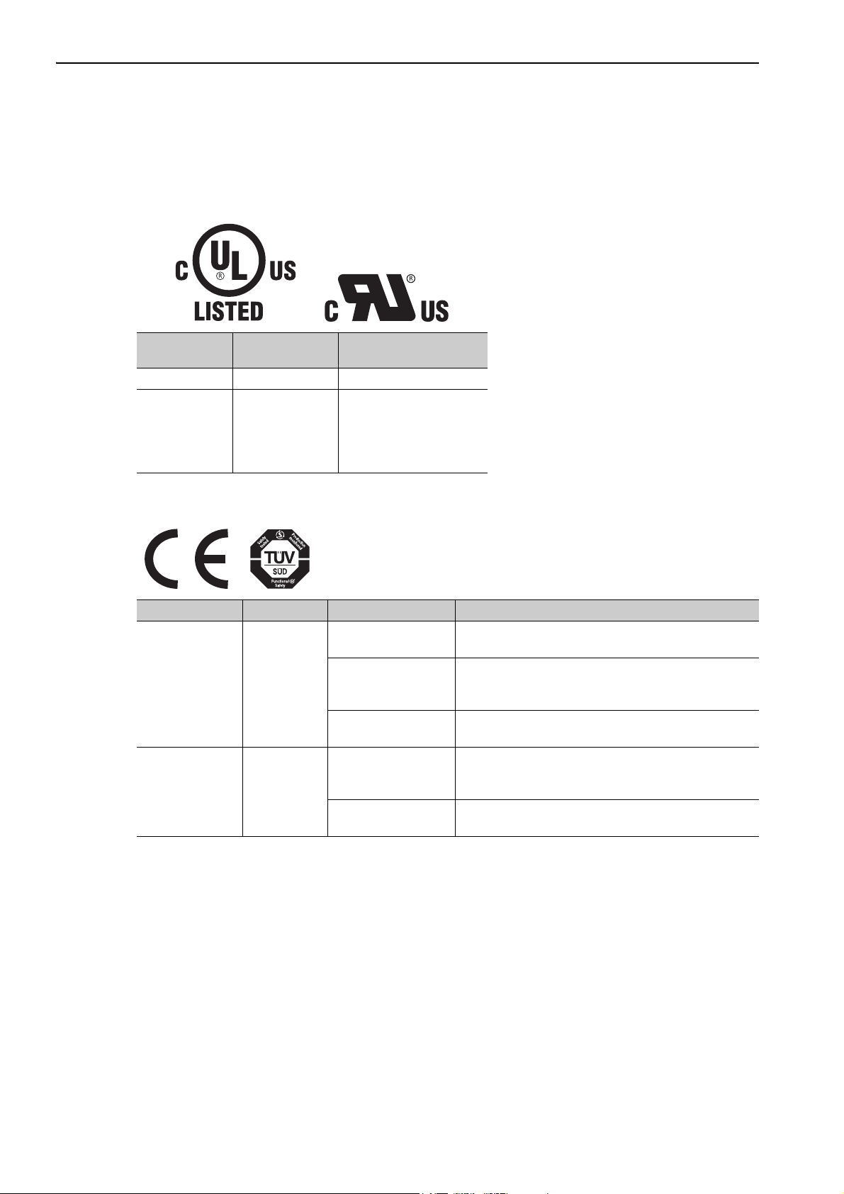
North American Safety Standards (UL)
Model
SERVOPACK SGDV UL508C (E147823)
•SGMJV
•SGMAV
Servomotor
•SGMPS
• SGMGV
•SGMSV
UL Standards
(UL File No.)
UL1004 (E165827)
European Directives
Model European Directives Harmonized Standards
Machinery Directive
2006/42/EC
SERVOPACK SGDV
•SGMJV
•SGMAV
Servomotor
•SGMPS
• SGMGV
•SGMSV
EMC Directive
2004/108/EC
Low Voltage Directive
2006/95/EC
EMC Directive
2004/108/EC
Low Voltage Directive
2006/95/EC
EN ISO13849-1: 2008
EN 954-1
EN 55011 group 1 class A
EN 61000-6-2
EN 61800-3
EN 50178
EN 61800-5-1
EN 55011 group 1 class A
EN 61000-6-2
EN 61800-3
EN 60034-1
EN 60034-5
xiv
Page 15
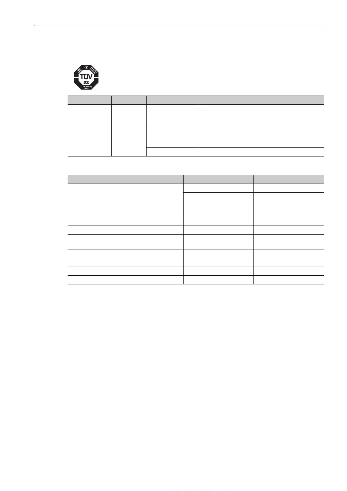
Safety Standards
Model Safety Standards Standards
EN ISO13849-1: 2008
Safety of Machinery
SERVOPACK SGDV
Functional Safety
EMC IEC 61326-3-1
EN 954-1
IEC 60204-1
IEC 61508 series
IEC 62061
IEC 61800-5-2
Safe Performance
Items Standards Performance Level
Safety Integrity Level
Probability of Dangerous Failure per Hour
Category EN 954-1 Category 3
Performance Level EN ISO 13849-1 PL d (Category 3)
Mean Time to Dangerous Failure of Each
Channel
Average Diagnostic Coverage EN ISO 13849-1 DCave: Low
Stop Category IEC 60204-1 Stop category 0
Safety Function IEC 61800-5-2 STO
Proof test Interval IEC 61508 10 years
IEC 61508 SIL2
IEC 62061 SILCL2
IEC 61508
IEC 62061
EN ISO 13849-1 MTTFd: High
PFH ⇐ 1.7×10
(0.17% of SIL2)
-9
[1/h]
xv
Page 16

Contents
Chapter 1 Outline . . . . . . . . . . . . . . . . . . . . . . . . . . . . . . . . . . . . . . . . . . . .1-1
1.1 Σ-V Series SERVOPACKs . . . . . . . . . . . . . . . . . . . . . . . . . . . . . . . . . . . . . . . 1-2
1.2 Part Names . . . . . . . . . . . . . . . . . . . . . . . . . . . . . . . . . . . . . . . . . . . . . . . . . . 1-2
1.3 SERVOPACK Ratings and Specifications . . . . . . . . . . . . . . . . . . . . . . . . . . . 1-3
1.3.1 Ratings. . . . . . . . . . . . . . . . . . . . . . . . . . . . . . . . . . . . . . . . . . . . . . . . . . . . . . . . . . . . . . . . 1-3
1.3.2 Basic Specifications . . . . . . . . . . . . . . . . . . . . . . . . . . . . . . . . . . . . . . . . . . . . . . . . . . . . . . 1-5
1.3.3 MECHATROLINK-III Function Specifications . . . . . . . . . . . . . . . . . . . . . . . . . . . . . . . . . . 1-8
1.4 SERVOPACK Internal Block Diagrams . . . . . . . . . . . . . . . . . . . . . . . . . . . . . 1-9
1.4.1 Single-phase 100 V, SGDV-R70F21A, -R90F21A, -2R1F21A Models . . . . . . . . . . . . . . . 1-9
1.4.2 Single-phase 100 V, SGDV-2R8F21A Model. . . . . . . . . . . . . . . . . . . . . . . . . . . . . . . . . . . 1-9
1.4.3 Single-phase 200 V, SGDV-120A21A008000 Model . . . . . . . . . . . . . . . . . . . . . . . . . . . . 1-10
1.4.4 Three-phase 200 V, SGDV-R70A21, -R90A21, -1R6A21 Models . . . . . . . . . . . . .1-10
1.4.5 Three-phase 200 V, SGDV-2R8A21 Model. . . . . . . . . . . . . . . . . . . . . . . . . . . . . . . . . . 1-11
1.4.6 Three-phase 200 V, SGDV-3R8A21A, -5R5A21A, -7R6A21A Models . . . . . . . . . . . . . . 1-11
1.4.7 Three-phase 200 V, SGDV-120A21A Model . . . . . . . . . . . . . . . . . . . . . . . . . . . . . . . . . .1-12
1.4.8 Three-phase 200 V, SGDV-180A21A, -200A21A Models . . . . . . . . . . . . . . . . . . . . . . . . 1-12
1.4.9 Three-phase 200 V, SGDV-330A21A Model . . . . . . . . . . . . . . . . . . . . . . . . . . . . . . . . . .1-13
1.4.10 Three-phase 200 V, SGDV-470A21A, -550A21A Models . . . . . . . . . . . . . . . . . . . . . . . 1-13
1.4.11 Three-phase 200 V SGDV-590A21A, -780A21A Models . . . . . . . . . . . . . . . . . . . . . . . . 1-14
1.4.12 Three-phase 400 V, SGDV-1R9D21A, -3R5D21A, -5R4D21A Models . . . . . . . . . . . . . 1-14
1.4.13 Three-phase 400 V, SGDV-8R4D21A, -120D21A Models . . . . . . . . . . . . . . . . . . . . . . . 1-15
1.4.14 Three-phase 400 V, SGDV-170D21A Model . . . . . . . . . . . . . . . . . . . . . . . . . . . . . . . . . 1-15
1.4.15 Three-phase 400 V, SGDV-210D21A, -260D21A Models . . . . . . . . . . . . . . . . . . . . . . . 1-16
1.4.16 Three-phase 400 V, SGDV-280D21A, -370D21A Models . . . . . . . . . . . . . . . . . . . . . . . 1-16
1.5 Examples of Servo System Configurations . . . . . . . . . . . . . . . . . . . . . . . . . 1-17
1.5.1 Connecting to SGDV-F21A SERVOPACK . . . . . . . . . . . . . . . . . . . . . . . . . . . . . . . 1-17
1.5.2 Connecting to SGDV-A21 SERVOPACK. . . . . . . . . . . . . . . . . . . . . . . . . . . . . . . 1-18
1.5.3 Connecting to SGDV-D21A SERVOPACK . . . . . . . . . . . . . . . . . . . . . . . . . . . . . . . 1-20
1.6 SERVOPACK Model Designation. . . . . . . . . . . . . . . . . . . . . . . . . . . . . . . . . 1-21
1.7 Inspection and Maintenance . . . . . . . . . . . . . . . . . . . . . . . . . . . . . . . . . . . . 1-22
About this Manual . . . . . . . . . . . . . . . . . . . . . . . . . . . . . . . . . . . . . . . . . . . . . . . . . . . . . . . . iii
Safety Precautions. . . . . . . . . . . . . . . . . . . . . . . . . . . . . . . . . . . . . . . . . . . . . . . . . . . . . . . vii
Warranty. . . . . . . . . . . . . . . . . . . . . . . . . . . . . . . . . . . . . . . . . . . . . . . . . . . . . . . . . . . . . . . xii
Harmonized Standards . . . . . . . . . . . . . . . . . . . . . . . . . . . . . . . . . . . . . . . . . . . . . . . . . . . xiv
xvi
Chapter 2 Panel Display and Operation of Digital Operator . . . . . . . . . . . .2-1
2.1 Panel Display . . . . . . . . . . . . . . . . . . . . . . . . . . . . . . . . . . . . . . . . . . . . . . . . . 2-2
2.1.1 Status Display . . . . . . . . . . . . . . . . . . . . . . . . . . . . . . . . . . . . . . . . . . . . . . . . . . . . . . . . . .2-2
2.1.2 Alarm and Warning Display . . . . . . . . . . . . . . . . . . . . . . . . . . . . . . . . . . . . . . . . . . . . . . . .2-2
2.1.3 Hard Wire Base Block Display . . . . . . . . . . . . . . . . . . . . . . . . . . . . . . . . . . . . . . . . . . . . . .2-2
2.1.4 Overtravel Display . . . . . . . . . . . . . . . . . . . . . . . . . . . . . . . . . . . . . . . . . . . . . . . . . . . . . . . 2-2
2.2 Operation of Digital Operator . . . . . . . . . . . . . . . . . . . . . . . . . . . . . . . . . . . . . 2-3
2.3 Utility Functions (Fn). . . . . . . . . . . . . . . . . . . . . . . . . . . . . . . . . . . . . . . 2-3
2.4 Parameters (Pn) . . . . . . . . . . . . . . . . . . . . . . . . . . . . . . . . . . . . . . . . . . 2-4
2.4.1 Parameter Classification . . . . . . . . . . . . . . . . . . . . . . . . . . . . . . . . . . . . . . . . . . . . . . . . . .2-4
2.4.2 Notation for Parameters . . . . . . . . . . . . . . . . . . . . . . . . . . . . . . . . . . . . . . . . . . . . . . . . . . . 2-4
2.4.3 Setting Parameters . . . . . . . . . . . . . . . . . . . . . . . . . . . . . . . . . . . . . . . . . . . . . . . . . . . . . .2-5
2.5 Monitor Displays (Un) . . . . . . . . . . . . . . . . . . . . . . . . . . . . . . . . . . . . . . 2-7
Page 17

Chapter 3 Wiring and Connection . . . . . . . . . . . . . . . . . . . . . . . . . . . . . . . .3-1
3.1 Main Circuit Wiring. . . . . . . . . . . . . . . . . . . . . . . . . . . . . . . . . . . . . . . . . . . . . 3-2
3.1.1 Main Circuit Terminals . . . . . . . . . . . . . . . . . . . . . . . . . . . . . . . . . . . . . . . . . . . . . . . . . . . . 3-2
3.1.2 Using a Standard Power Supply
(Single-phase 100 V, Three-phase 200 V, or Three-phase 400 V) . . . . . . . . . . . . . . . . . .3-3
3.1.3 Using the SERVOPACK with Single-phase, 200 V Power Input . . . . . . . . . . . . . . . . . . . 3-11
3.1.4 Using the SERVOPACK with a DC Power Input . . . . . . . . . . . . . . . . . . . . . . . . . . . . . . .3-14
3.1.5 Using More Than One SERVOPACK . . . . . . . . . . . . . . . . . . . . . . . . . . . . . . . . . . . . . . . . 3-16
3.1.6 General Precautions for Wiring . . . . . . . . . . . . . . . . . . . . . . . . . . . . . . . . . . . . . . . . . . . .3-17
3.2 I/O Signal Connections . . . . . . . . . . . . . . . . . . . . . . . . . . . . . . . . . . . . . . . . 3-18
3.2.1 I/O Signal (CN1) Names and Functions. . . . . . . . . . . . . . . . . . . . . . . . . . . . . . . . . . . . . . 3-18
3.2.2 Safety Function Signal (CN8) Names and Functions. . . . . . . . . . . . . . . . . . . . . . . . . . . .3-19
3.2.3 Example of I/O Signal Connections . . . . . . . . . . . . . . . . . . . . . . . . . . . . . . . . . . . . . . . . .3-20
3.3 I/O Signal Allocations. . . . . . . . . . . . . . . . . . . . . . . . . . . . . . . . . . . . . . . . . . 3-21
3.3.1 Input Signal Allocations . . . . . . . . . . . . . . . . . . . . . . . . . . . . . . . . . . . . . . . . . . . . . . . . . .3-21
3.3.2 Output Signal Allocations . . . . . . . . . . . . . . . . . . . . . . . . . . . . . . . . . . . . . . . . . . . . . . . . .3-23
3.4 Examples of Connection to Host Controller. . . . . . . . . . . . . . . . . . . . . . . . . 3-24
3.4.1 Sequence Input Circuit. . . . . . . . . . . . . . . . . . . . . . . . . . . . . . . . . . . . . . . . . . . . . . . . . . .3-24
3.4.2 Sequence Output Circuit . . . . . . . . . . . . . . . . . . . . . . . . . . . . . . . . . . . . . . . . . . . . . . . . .3-25
3.5 Wiring MECHATROLINK-III Communications . . . . . . . . . . . . . . . . . . . . . . . 3-27
3.6 Encoder Connection . . . . . . . . . . . . . . . . . . . . . . . . . . . . . . . . . . . . . . . . . . 3-28
3.6.1 Encoder Signal (CN2) Names and Functions . . . . . . . . . . . . . . . . . . . . . . . . . . . . . . . . .3-28
3.6.2 Encoder Connection Examples . . . . . . . . . . . . . . . . . . . . . . . . . . . . . . . . . . . . . . . . . . . .3-28
3.7 Connecting Regenerative Resistors . . . . . . . . . . . . . . . . . . . . . . . . . . . . . . 3-30
3.7.1 Connecting Regenerative Resistors. . . . . . . . . . . . . . . . . . . . . . . . . . . . . . . . . . . . . . . . .3-30
3.7.2 Setting Regenerative Resistor Capacity. . . . . . . . . . . . . . . . . . . . . . . . . . . . . . . . . . . . . . 3-32
3.8 Noise Control and Measures for Harmonic Suppression. . . . . . . . . . . . . . . 3-33
3.8.1 Wiring for Noise Control . . . . . . . . . . . . . . . . . . . . . . . . . . . . . . . . . . . . . . . . . . . . . . . . . . 3-33
3.8.2 Precautions on Connecting Noise Filter. . . . . . . . . . . . . . . . . . . . . . . . . . . . . . . . . . . . . . 3-35
3.8.3 Connecting a Reactor for Harmonic Suppression . . . . . . . . . . . . . . . . . . . . . . . . . . . . . . 3-36
Chapter 4 Operation . . . . . . . . . . . . . . . . . . . . . . . . . . . . . . . . . . . . . . . . . .4-1
4.1 MECHATROLINK-III Communications Settings . . . . . . . . . . . . . . . . . . . . . . 4-3
4.1.1 Setting Switches S1, S2, and S3 . . . . . . . . . . . . . . . . . . . . . . . . . . . . . . . . . . . . . . . . . . . . 4-3
4.2 MECHATROLINK-III Commands . . . . . . . . . . . . . . . . . . . . . . . . . . . . . . . . . 4-4
4.3 Basic Functions Settings . . . . . . . . . . . . . . . . . . . . . . . . . . . . . . . . . . . . . . . . 4-4
4.3.1 Servomotor Rotation Direction. . . . . . . . . . . . . . . . . . . . . . . . . . . . . . . . . . . . . . . . . . . . . . 4-4
4.3.2 Overtravel. . . . . . . . . . . . . . . . . . . . . . . . . . . . . . . . . . . . . . . . . . . . . . . . . . . . . . . . . . . . . . 4-5
4.3.3 Software Limit Settings. . . . . . . . . . . . . . . . . . . . . . . . . . . . . . . . . . . . . . . . . . . . . . . . . . . .4-8
4.3.4 Holding Brakes. . . . . . . . . . . . . . . . . . . . . . . . . . . . . . . . . . . . . . . . . . . . . . . . . . . . . . . . . . 4-9
4.3.5 Stopping Servomotors after SV_OFF Command or Alarm Occurrence. . . . . . . . . . . . . . 4-14
4.3.6 Instantaneous Power Interruption Settings . . . . . . . . . . . . . . . . . . . . . . . . . . . . . . . . . . .4-16
4.3.7 SEMI F47 Function (Torque Limit Function for Low DC Power Supply Voltage
for Main Circuit) . . . . . . . . . . . . . . . . . . . . . . . . . . . . . . . . . . . . . . . . . . . . . . . . . . . . . . . .4-17
4.3.8 Setting Motor Overload Detection Level . . . . . . . . . . . . . . . . . . . . . . . . . . . . . . . . . . . . .4-20
4.4 Trial Operation . . . . . . . . . . . . . . . . . . . . . . . . . . . . . . . . . . . . . . . . . . . . . . . 4-22
4.4.1 Inspection and Checking before Trial Operation . . . . . . . . . . . . . . . . . . . . . . . . . . . . . . . 4-22
4.4.2 Trial Operation via MECHATROLINK-III . . . . . . . . . . . . . . . . . . . . . . . . . . . . . . . . . . . . .4-23
4.4.3 Electronic Gear . . . . . . . . . . . . . . . . . . . . . . . . . . . . . . . . . . . . . . . . . . . . . . . . . . . . . . . .4-24
4.4.4 Encoder Output Pulses . . . . . . . . . . . . . . . . . . . . . . . . . . . . . . . . . . . . . . . . . . . . . . . . . .4-26
4.4.5 Setting Encoder Output Pulse . . . . . . . . . . . . . . . . . . . . . . . . . . . . . . . . . . . . . . . . . . . . .4-27
4.5 Test Without Motor Function . . . . . . . . . . . . . . . . . . . . . . . . . . . . . . . . . . . . 4-28
4.5.1 Motor Information . . . . . . . . . . . . . . . . . . . . . . . . . . . . . . . . . . . . . . . . . . . . . . . . . . . . . . .4-28
4.5.2 Motor Position and Speed Responses. . . . . . . . . . . . . . . . . . . . . . . . . . . . . . . . . . . . . . .4-29
4.5.3 Limitations . . . . . . . . . . . . . . . . . . . . . . . . . . . . . . . . . . . . . . . . . . . . . . . . . . . . . . . . . . . .4-30
4.5.4 Digital Operator Displays during Testing without Motor . . . . . . . . . . . . . . . . . . . . . . . . . . 4-31
xvii
Page 18

4.6 Limiting Torque . . . . . . . . . . . . . . . . . . . . . . . . . . . . . . . . . . . . . . . . . . . . . . . 4-32
4.6.1 Internal Torque Limit. . . . . . . . . . . . . . . . . . . . . . . . . . . . . . . . . . . . . . . . . . . . . . . . . . . . . 4-32
4.6.2 External Torque Limit . . . . . . . . . . . . . . . . . . . . . . . . . . . . . . . . . . . . . . . . . . . . . . . . . . . . 4-33
4.6.3 Checking Output Torque Limiting during Operation . . . . . . . . . . . . . . . . . . . . . . . . . . . . . 4-34
4.7 Absolute Encoders . . . . . . . . . . . . . . . . . . . . . . . . . . . . . . . . . . . . . . . . . . . . 4-35
4.7.1 Connecting the Absolute Encoder . . . . . . . . . . . . . . . . . . . . . . . . . . . . . . . . . . . . . . . . . .4-36
4.7.2 Absolute Data Request (SENS ON Command) . . . . . . . . . . . . . . . . . . . . . . . . . . . . . . . . 4-38
4.7.3 Battery Replacement . . . . . . . . . . . . . . . . . . . . . . . . . . . . . . . . . . . . . . . . . . . . . . . . . . . . 4-39
4.7.4 Absolute Encoder Setup and Reinitialization . . . . . . . . . . . . . . . . . . . . . . . . . . . . . . . . . . 4-41
4.7.5 Absolute Data Reception Sequence . . . . . . . . . . . . . . . . . . . . . . . . . . . . . . . . . . . . . . . . 4-42
4.7.6 Multiturn Limit Setting. . . . . . . . . . . . . . . . . . . . . . . . . . . . . . . . . . . . . . . . . . . . . . . . . . . . 4-47
4.7.7 Multiturn Limit Disagreement Alarm (A.CC0) . . . . . . . . . . . . . . . . . . . . . . . . . . . . . . . . . . 4-48
4.7.8 Absolute Encoder Origin Offset . . . . . . . . . . . . . . . . . . . . . . . . . . . . . . . . . . . . . . . . . . . .4-49
4.8 Other Output Signals . . . . . . . . . . . . . . . . . . . . . . . . . . . . . . . . . . . . . . . . . . 4-50
4.8.1 Servo Alarm Output Signal (ALM) . . . . . . . . . . . . . . . . . . . . . . . . . . . . . . . . . . . . . . . . . . 4-50
4.8.2 Warning Output Signal (/WARN) . . . . . . . . . . . . . . . . . . . . . . . . . . . . . . . . . . . . . . . . . . .4-50
4.8.3 Rotation Detection Output Signal (/TGON) . . . . . . . . . . . . . . . . . . . . . . . . . . . . . . . . . . . 4-51
4.8.4 Servo Ready Output Signal (/S-RDY) . . . . . . . . . . . . . . . . . . . . . . . . . . . . . . . . . . . . . . .4-51
4.8.5 Speed Coincidence Output Signal (/V-CMP) . . . . . . . . . . . . . . . . . . . . . . . . . . . . . . . . . .4-52
4.8.6 Positioning Completed Output Signal (/COIN) . . . . . . . . . . . . . . . . . . . . . . . . . . . . . . . . .4-53
4.8.7 Positioning Near Output Signal (/NEAR) . . . . . . . . . . . . . . . . . . . . . . . . . . . . . . . . . . . . . 4-54
4.8.8 Speed Limit Detection Signal (/VLT) . . . . . . . . . . . . . . . . . . . . . . . . . . . . . . . . . . . . . . . .4-55
4.9 Safety Function . . . . . . . . . . . . . . . . . . . . . . . . . . . . . . . . . . . . . . . . . . . . . . 4-57
4.9.1 Hard Wire Base Block (HWBB) Function . . . . . . . . . . . . . . . . . . . . . . . . . . . . . . . . . . . . . 4-57
4.9.2 External Device Monitor (EDM1) . . . . . . . . . . . . . . . . . . . . . . . . . . . . . . . . . . . . . . . . . . .4-63
4.9.3 Application Example of Safety Functions. . . . . . . . . . . . . . . . . . . . . . . . . . . . . . . . . . . . .4-65
4.9.4 Confirming Safety Functions . . . . . . . . . . . . . . . . . . . . . . . . . . . . . . . . . . . . . . . . . . . . . . 4-66
4.9.5 Connecting a Safety Function Device . . . . . . . . . . . . . . . . . . . . . . . . . . . . . . . . . . . . . . . 4-67
4.9.6 Precautions for Safety Functions . . . . . . . . . . . . . . . . . . . . . . . . . . . . . . . . . . . . . . . . . . .4-69
Chapter 5 Adjustments . . . . . . . . . . . . . . . . . . . . . . . . . . . . . . . . . . . . . . . .5-1
5.1 Type of Adjustments and Basic Adjustment Procedure . . . . . . . . . . . . . . . . .5-3
5.1.1 Adjustments . . . . . . . . . . . . . . . . . . . . . . . . . . . . . . . . . . . . . . . . . . . . . . . . . . . . . . . . . . . . 5-3
5.1.2 Basic Adjustment Procedure . . . . . . . . . . . . . . . . . . . . . . . . . . . . . . . . . . . . . . . . . . . . . . . 5-4
5.1.3 Monitoring Operation during Adjustment . . . . . . . . . . . . . . . . . . . . . . . . . . . . . . . . . . . . . . 5-5
5.1.4 Safety Precautions on Adjustment of Servo Gains . . . . . . . . . . . . . . . . . . . . . . . . . . . . . . 5-8
5.2 Tuning-less Function . . . . . . . . . . . . . . . . . . . . . . . . . . . . . . . . . . . . . . . . . . 5-11
5.2.1 Tuning-less Function . . . . . . . . . . . . . . . . . . . . . . . . . . . . . . . . . . . . . . . . . . . . . . . . . . . . 5-11
5.2.2 Tuning-less Levels Setting (Fn200) Procedure . . . . . . . . . . . . . . . . . . . . . . . . . . . . . . . . 5-14
5.2.3 Related Parameters . . . . . . . . . . . . . . . . . . . . . . . . . . . . . . . . . . . . . . . . . . . . . . . . . . . . . 5-16
5.3 Advanced Autotuning (Fn201) . . . . . . . . . . . . . . . . . . . . . . . . . . . . . . . . . . . 5-17
5.3.1 Advanced Autotuning. . . . . . . . . . . . . . . . . . . . . . . . . . . . . . . . . . . . . . . . . . . . . . . . . . . .5-17
5.3.2 Advanced Autotuning Procedure . . . . . . . . . . . . . . . . . . . . . . . . . . . . . . . . . . . . . . . . . . 5-20
5.3.3 Related Parameters . . . . . . . . . . . . . . . . . . . . . . . . . . . . . . . . . . . . . . . . . . . . . . . . . . . . . 5-26
5.4 Advanced Autotuning by Reference (Fn202) . . . . . . . . . . . . . . . . . . . . . . . . 5-27
5.4.1 Advanced Autotuning by Reference. . . . . . . . . . . . . . . . . . . . . . . . . . . . . . . . . . . . . . . . .5-27
5.4.2 Advanced Autotuning by Reference Procedure . . . . . . . . . . . . . . . . . . . . . . . . . . . . . . . 5-29
5.4.3 Related Parameters . . . . . . . . . . . . . . . . . . . . . . . . . . . . . . . . . . . . . . . . . . . . . . . . . . . . . 5-33
5.5 One-parameter Tuning (Fn203) . . . . . . . . . . . . . . . . . . . . . . . . . . . . . . . . . . 5-34
5.5.1 One-parameter Tuning . . . . . . . . . . . . . . . . . . . . . . . . . . . . . . . . . . . . . . . . . . . . . . . . . . .5-34
5.5.2 One-parameter Tuning Procedure . . . . . . . . . . . . . . . . . . . . . . . . . . . . . . . . . . . . . . . . . .5-35
5.5.3 One-parameter Tuning Example . . . . . . . . . . . . . . . . . . . . . . . . . . . . . . . . . . . . . . . . . . .5-41
5.5.4 Related Parameters . . . . . . . . . . . . . . . . . . . . . . . . . . . . . . . . . . . . . . . . . . . . . . . . . . . . . 5-42
5.6 Anti-Resonance Control Adjustment Function (Fn204) . . . . . . . . . . . . . . . . 5-43
5.6.1 Anti-Resonance Control Adjustment Function . . . . . . . . . . . . . . . . . . . . . . . . . . . . . . . . . 5-43
5.6.2 Anti-Resonance Control Adjustment Function Operating Procedure . . . . . . . . . . . . . . . . 5-44
5.6.3 Related Parameters . . . . . . . . . . . . . . . . . . . . . . . . . . . . . . . . . . . . . . . . . . . . . . . . . . . . . 5-48
xviii
Page 19

5.7 Vibration Suppression Function (Fn205) . . . . . . . . . . . . . . . . . . . . . . . . . . . 5-49
5.7.1 Vibration Suppression Function . . . . . . . . . . . . . . . . . . . . . . . . . . . . . . . . . . . . . . . . . . . . 5-49
5.7.2 Vibration Suppression Function Operating Procedure . . . . . . . . . . . . . . . . . . . . . . . . . . .5-50
5.7.3 Related Parameters . . . . . . . . . . . . . . . . . . . . . . . . . . . . . . . . . . . . . . . . . . . . . . . . . . . . . 5-53
5.8 Additional Adjustment Function . . . . . . . . . . . . . . . . . . . . . . . . . . . . . . . . . . 5-54
5.8.1 Switching Gain Settings . . . . . . . . . . . . . . . . . . . . . . . . . . . . . . . . . . . . . . . . . . . . . . . . . .5-54
5.8.2 Manual Adjustment of Friction Compensation . . . . . . . . . . . . . . . . . . . . . . . . . . . . . . . . .5-58
5.8.3 Current Control Mode Selection Function . . . . . . . . . . . . . . . . . . . . . . . . . . . . . . . . . . . . 5-60
5.8.4 Current Gain Level Setting. . . . . . . . . . . . . . . . . . . . . . . . . . . . . . . . . . . . . . . . . . . . . . . .5-60
5.8.5 Speed Detection Method Selection . . . . . . . . . . . . . . . . . . . . . . . . . . . . . . . . . . . . . . . . . 5-60
5.8.6 Backlash Compensation Function . . . . . . . . . . . . . . . . . . . . . . . . . . . . . . . . . . . . . . . . . .5-61
5.9 Compatible Adjustment Function. . . . . . . . . . . . . . . . . . . . . . . . . . . . . . . . . 5-67
5.9.1 Feedforward Reference . . . . . . . . . . . . . . . . . . . . . . . . . . . . . . . . . . . . . . . . . . . . . . . . . .5-67
5.9.2 Mode Switch (P/PI Switching) . . . . . . . . . . . . . . . . . . . . . . . . . . . . . . . . . . . . . . . . . . . . .5-68
5.9.3 Torque Reference Filter . . . . . . . . . . . . . . . . . . . . . . . . . . . . . . . . . . . . . . . . . . . . . . . . . . 5-70
5.9.4 Position Integral . . . . . . . . . . . . . . . . . . . . . . . . . . . . . . . . . . . . . . . . . . . . . . . . . . . . . . . .5-72
Chapter 6 Utility Functions (Fn) . . . . . . . . . . . . . . . . . . . . . . . . . . . . .6-1
6.1 List of Utility Functions. . . . . . . . . . . . . . . . . . . . . . . . . . . . . . . . . . . . . . . . . . 6-2
6.2 Alarm History Display (Fn000). . . . . . . . . . . . . . . . . . . . . . . . . . . . . . . . . . . . 6-3
6.3 JOG Operation (Fn002) . . . . . . . . . . . . . . . . . . . . . . . . . . . . . . . . . . . . . . . . . 6-4
6.4 Origin Search (Fn003) . . . . . . . . . . . . . . . . . . . . . . . . . . . . . . . . . . . . . . . . . . 6-6
6.5 Program JOG Operation (Fn004) . . . . . . . . . . . . . . . . . . . . . . . . . . . . . . . . . 6-8
6.6 Initializing Parameter Settings (Fn005) . . . . . . . . . . . . . . . . . . . . . . . . . . . . 6-13
6.7 Clearing Alarm History (Fn006) . . . . . . . . . . . . . . . . . . . . . . . . . . . . . . . . . . 6-14
6.8 Offset Adjustment of Analog Monitor Output (Fn00C) . . . . . . . . . . . . . . . . . 6-15
6.9 Gain Adjustment of Analog Monitor Output (Fn00D) . . . . . . . . . . . . . . . . . . 6-17
6.10 Automatic Offset-Signal Adjustment of the Motor Current Detection Signal
(Fn00E) . . . . . . . . . . . . . . . . . . . . . . . . . . . . . . . . . . . . . . . . . . . . . . . . . . . . 6-19
6.11 Manual Offset-Signal Adjustment of the Motor Current Detection Signal
(Fn00F) . . . . . . . . . . . . . . . . . . . . . . . . . . . . . . . . . . . . . . . . . . . . . . . . . . . . 6-20
6.12 Write Prohibited Setting (Fn010) . . . . . . . . . . . . . . . . . . . . . . . . . . . . . . . . 6-22
6.13 Servomotor Model Display (Fn011) . . . . . . . . . . . . . . . . . . . . . . . . . . . . . . 6-24
6.14 Software Version Display (Fn012) . . . . . . . . . . . . . . . . . . . . . . . . . . . . . . . 6-25
6.15 Resetting Configuration Errors in Option Modules (Fn014). . . . . . . . . . . . 6-26
6.16 Vibration Detection Level Initialization (Fn01B) . . . . . . . . . . . . . . . . . . . . . 6-27
6.17 Display of SERVOPACK and Servomotor ID (Fn01E) . . . . . . . . . . . . . . . . 6-29
6.18 Display of Servomotor ID in Feedback Option Module (Fn01F) . . . . . . . . 6-31
6.19 Origin Setting (Fn020) . . . . . . . . . . . . . . . . . . . . . . . . . . . . . . . . . . . . . . . . 6-33
6.20 Software Reset (Fn030). . . . . . . . . . . . . . . . . . . . . . . . . . . . . . . . . . . . . . . 6-34
6.21 EasyFFT (Fn206). . . . . . . . . . . . . . . . . . . . . . . . . . . . . . . . . . . . . . . . . . . . 6-35
6.22 Online Vibration Monitor (Fn207). . . . . . . . . . . . . . . . . . . . . . . . . . . . . . . . 6-39
Chapter 7 Monitor Displays (Un) . . . . . . . . . . . . . . . . . . . . . . . . . . . .7-1
7.1 List of Monitor Displays . . . . . . . . . . . . . . . . . . . . . . . . . . . . . . . . . . . . . . . . . 7-2
7.2 Viewing Monitor Displays. . . . . . . . . . . . . . . . . . . . . . . . . . . . . . . . . . . . . . . . 7-3
7.3 Monitoring Input Signals . . . . . . . . . . . . . . . . . . . . . . . . . . . . . . . . . . . . . . . . 7-4
7.3.1 Interpreting Input Signal Display Status . . . . . . . . . . . . . . . . . . . . . . . . . . . . . . . . . . . . . . .7-4
7.3.2 Input Signal Display Example . . . . . . . . . . . . . . . . . . . . . . . . . . . . . . . . . . . . . . . . . . . . . . 7-5
xix
Page 20

7.4 Monitoring Output Signals . . . . . . . . . . . . . . . . . . . . . . . . . . . . . . . . . . . . . . . 7-6
7.4.1 Interpreting Output Signal Display Status . . . . . . . . . . . . . . . . . . . . . . . . . . . . . . . . . . . . .7-6
7.4.2 Output Signal Display Example . . . . . . . . . . . . . . . . . . . . . . . . . . . . . . . . . . . . . . . . . . . . .7-6
7.5 Monitoring Safety Input Signals . . . . . . . . . . . . . . . . . . . . . . . . . . . . . . . . . . . 7-7
7.5.1 Interpreting Safety Input Signal Display Status . . . . . . . . . . . . . . . . . . . . . . . . . . . . . . . . . 7-7
7.5.2 Safety Input Signal Display Example . . . . . . . . . . . . . . . . . . . . . . . . . . . . . . . . . . . . . . . . .7-7
Chapter 8 Fully-closed Loop Control. . . . . . . . . . . . . . . . . . . . . . . . . . . . . .8-1
8.1 System Configuration and Connection Example for SERVOPACK
with Fully-closed Loop Control. . . . . . . . . . . . . . . . . . . . . . . . . . . . . . . . . . . . 8-2
8.1.1 System Configuration. . . . . . . . . . . . . . . . . . . . . . . . . . . . . . . . . . . . . . . . . . . . . . . . . . . . . 8-2
8.1.2 Internal Block Diagram of Fully-closed Loop Control. . . . . . . . . . . . . . . . . . . . . . . . . . . . . 8-3
8.1.3 Serial Converter Unit . . . . . . . . . . . . . . . . . . . . . . . . . . . . . . . . . . . . . . . . . . . . . . . . . . . . . 8-4
8.1.4 Example of Connections to External Encoders . . . . . . . . . . . . . . . . . . . . . . . . . . . . . . . . . 8-6
8.1.5 Encoder Output Pulse Signals from SERVOPACK with an External Encoder
by Renishaw plc. . . . . . . . . . . . . . . . . . . . . . . . . . . . . . . . . . . . . . . . . . . . . . . . . . . . . . . . .8-7
8.1.6 Precautions When Using an External Incremental Encoder by Magnescale . . . . . . . . . . . 8-8
8.2 SERVOPACK Startup Procedure . . . . . . . . . . . . . . . . . . . . . . . . . . . . . . . . . 8-11
8.3 Parameter Settings for Fully-closed Loop Control . . . . . . . . . . . . . . . . . . . . 8-13
8.3.1 Motor Rotation Direction . . . . . . . . . . . . . . . . . . . . . . . . . . . . . . . . . . . . . . . . . . . . . . . . .8-14
8.3.2 Sine Wave Pitch (Frequency) for an External Encoder . . . . . . . . . . . . . . . . . . . . . . . . . . 8-16
8.3.3 Setting Encoder Output Pulses (PAO, PBO, and PCO) . . . . . . . . . . . . . . . . . . . . . . . . . . 8-16
8.3.4 External Absolute Encoder Data Reception Sequence . . . . . . . . . . . . . . . . . . . . . . . . . .8-17
8.3.5 Electronic Gear . . . . . . . . . . . . . . . . . . . . . . . . . . . . . . . . . . . . . . . . . . . . . . . . . . . . . . . .8-20
8.3.6 Alarm Detection . . . . . . . . . . . . . . . . . . . . . . . . . . . . . . . . . . . . . . . . . . . . . . . . . . . . . . . . 8-21
8.3.7 Analog Monitor Signal . . . . . . . . . . . . . . . . . . . . . . . . . . . . . . . . . . . . . . . . . . . . . . . . . . .8-22
8.3.8 Speed Feedback Method during Fully-closed Loop Control . . . . . . . . . . . . . . . . . . . . . . 8-22
Chapter 9 Troubleshooting . . . . . . . . . . . . . . . . . . . . . . . . . . . . . . . . . . . . .9-1
9.1 Alarm Displays . . . . . . . . . . . . . . . . . . . . . . . . . . . . . . . . . . . . . . . . . . . . . . . . 9-2
9.1.1 List of Alarms . . . . . . . . . . . . . . . . . . . . . . . . . . . . . . . . . . . . . . . . . . . . . . . . . . . . . . . . . . . 9-2
9.1.2 Troubleshooting of Alarms . . . . . . . . . . . . . . . . . . . . . . . . . . . . . . . . . . . . . . . . . . . . . . . . .9-7
9.2 Warning Displays . . . . . . . . . . . . . . . . . . . . . . . . . . . . . . . . . . . . . . . . . . . . . 9-23
9.2.1 List of Warnings . . . . . . . . . . . . . . . . . . . . . . . . . . . . . . . . . . . . . . . . . . . . . . . . . . . . . . . . 9-23
9.2.2 Troubleshooting of Warnings . . . . . . . . . . . . . . . . . . . . . . . . . . . . . . . . . . . . . . . . . . . . . .9-25
9.3 Monitoring Communication Data on Occurrence of an Alarm or Warning . . 9-30
9.4 Troubleshooting Malfunction Based on Operation and
Conditions of the Servomotor . . . . . . . . . . . . . . . . . . . . . . . . . . . . . . . . . . . 9-31
Chapter 10 Appendix. . . . . . . . . . . . . . . . . . . . . . . . . . . . . . . . . . . . . . . . .10-1
10.1 List of Parameters . . . . . . . . . . . . . . . . . . . . . . . . . . . . . . . . . . . . . . . . . . . 10-2
10.1.1 Utility Functions . . . . . . . . . . . . . . . . . . . . . . . . . . . . . . . . . . . . . . . . . . . . . . . . . . . . . . .10-2
10.1.2 Parameters. . . . . . . . . . . . . . . . . . . . . . . . . . . . . . . . . . . . . . . . . . . . . . . . . . . . . . . . . . .10-3
10.1.3 MECHATROLINK-III Common Parameters. . . . . . . . . . . . . . . . . . . . . . . . . . . . . . . . . 10-37
10.2 List of Monitor Displays . . . . . . . . . . . . . . . . . . . . . . . . . . . . . . . . . . . . . . 10-45
10.3 Parameter Recording Table . . . . . . . . . . . . . . . . . . . . . . . . . . . . . . . . . . . 10-46
Index. . . . . . . . . . . . . . . . . . . . . . . . . . . . . . . . . . . . . . . . . . . . . . . . . . . Index-1
xx
Revision History
Page 21

1
Outline
1
Outline
1.1 Σ-V Series SERVOPACKs . . . . . . . . . . . . . . . . . . . . . . . . . . . . . . . . . . . . .1-2
1.2 Part Names . . . . . . . . . . . . . . . . . . . . . . . . . . . . . . . . . . . . . . . . . . . . . . . . 1-2
1.3 SERVOPACK Ratings and Specifications . . . . . . . . . . . . . . . . . . . . . . . . . 1-3
1.3.1 Ratings . . . . . . . . . . . . . . . . . . . . . . . . . . . . . . . . . . . . . . . . . . . . . . . . . . . . . . . . . . . . 1-3
1.3.2 Basic Specifications . . . . . . . . . . . . . . . . . . . . . . . . . . . . . . . . . . . . . . . . . . . . . . . . . .1-5
1.3.3 MECHATROLINK-III Function Specifications . . . . . . . . . . . . . . . . . . . . . . . . . . . . . . . 1-8
1.4 SERVOPACK Internal Block Diagrams . . . . . . . . . . . . . . . . . . . . . . . . . . .1-9
1.4.1 Single-phase 100 V, SGDV-R70F21A, -R90F21A, -2R1F21A Models . . . . . . . . . . . . 1-9
1.4.2 Single-phase 100 V, SGDV-2R8F21A Model . . . . . . . . . . . . . . . . . . . . . . . . . . . . . . . 1-9
1.4.3 Single-phase 200 V, SGDV-120A21A008000 Model . . . . . . . . . . . . . . . . . . . . . . . . 1-10
1.4.4 Three-phase 200 V, SGDV-R70A21, -R90A21, -1R6A21 Models . . . . . . . . . . 1-10
1.4.5 Three-phase 200 V, SGDV-2R8A21 Model . . . . . . . . . . . . . . . . . . . . . . . . . . . . . . 1-11
1.4.6 Three-phase 200 V, SGDV-3R8A21A, -5R5A21A, -7R6A21A Models . . . . . . . . . . . 1-11
1.4.7 Three-phase 200 V, SGDV-120A21A Model . . . . . . . . . . . . . . . . . . . . . . . . . . . . . . . 1-12
1.4.8 Three-phase 200 V, SGDV-180A21A, -200A21A Models . . . . . . . . . . . . . . . . . . . . . 1-12
1.4.9 Three-phase 200 V, SGDV-330A21A Model . . . . . . . . . . . . . . . . . . . . . . . . . . . . . . . 1-13
1.4.10 Three-phase 200 V, SGDV-470A21A, -550A21A Models . . . . . . . . . . . . . . . . . . . . 1-13
1.4.11 Three-phase 200 V SGDV-590A21A, -780A21A Models . . . . . . . . . . . . . . . . . . . . 1-14
1.4.12 Three-phase 400 V, SGDV-1R9D21A, -3R5D21A, -5R4D21A Models . . . . . . . . . . 1-14
1.4.13 Three-phase 400 V, SGDV-8R4D21A, -120D21A Models . . . . . . . . . . . . . . . . . . . 1-15
1.4.14 Three-phase 400 V, SGDV-170D21A Model . . . . . . . . . . . . . . . . . . . . . . . . . . . . . . 1-15
1.4.15 Three-phase 400 V, SGDV-210D21A, -260D21A Models . . . . . . . . . . . . . . . . . . . . 1-16
1.4.16 Three-phase 400 V, SGDV-280D21A, -370D21A Models . . . . . . . . . . . . . . . . . . . . 1-16
1.5 Examples of Servo System Configurations . . . . . . . . . . . . . . . . . . . . . . .1-17
1.5.1 Connecting to SGDV-F21A SERVOPACK . . . . . . . . . . . . . . . . . . . . . . . . . . . . 1-17
1.5.2 Connecting to SGDV-A21 SERVOPACK . . . . . . . . . . . . . . . . . . . . . . . . . . . 1-18
1.5.3 Connecting to SGDV-D21A SERVOPACK . . . . . . . . . . . . . . . . . . . . . . . . . . . 1-20
1.6 SERVOPACK Model Designation . . . . . . . . . . . . . . . . . . . . . . . . . . . . . .1-21
1.7 Inspection and Maintenance . . . . . . . . . . . . . . . . . . . . . . . . . . . . . . . . . . 1-22
1-1
Page 22

1 Outline
Refer to 1.6 SERVOPACK Model Designation.
Refer to 4.1.1 Setting Switches S1, S2, and S3.
Refer to 4.1.1 Setting Switches S1, S2, and S3.
Refer to 3.1 Main Circuit Wiring.
Refer to 3.1 Main Circuit Wiring.
Refer to 3.8.3 Connecting a Reactor for Harmonic
Suppression.
Refer to 3.1 Main Circuit Wiring.
Refer to 3.1 Main Circuit Wiring.
Note: When not using the safety function, use the SERVO-
PACK with the safety function’s jumper connector
(JZSP-CVH05-E, provided as an accessory) inserted.
For the connecting method, refer to 3.2.2 Safety Func-
tion Signal (CN8) Names and Functions.
For details on how to use the safety function, refer to
4.9 Safety Function.
Refer to 5.1.3 Monitoring Operation during Adjustment.
Refer to 2.1.1 Status Display.
Refer to 3.5 Wiring MECHATROLINK-III Communications.
Refer to 3.2 I/O Signal Connections.
Refer to 3.6 Encoder Connection.
64
Refer to 3.7 Connecting Regenerative Resistors.
1.1 Σ-V Series SERVOPACKs
The Σ-V Series SERVOPACKs are designed for applications that require frequent high-speed, high-precision positioning. The SERVOPACK makes the most of machine performance in the shortest time possible, thus contributing to improving productivity.
1.2 Part Names
This section describes the part names of SGDV SERVOPACK for MECHATROLINK-III communications
reference.
Serial number
DIP switch (S3)
Used to set MECHATROLINK communications.
Rotary switches (S1 and S2)
Used to set MECHATROLINK station address.
Nameplate (Found on side of SERVOPACK.)
Indicates the SERVOPACK model and ratings.
Charge indicator
Lights when the main circuit power supply is
ON and stays lit as long as the internal
capacitor remains charged. Therefore, do not
touch the SERVOPACK even after the power
supply is turned OFF if the indicator is lit. It may
result in electric shock.
Main circuit power supply terminals
Used for main circuit power supply input.
Control power supply terminals
Used for control power supply input.
Regenerative resistor connecting
terminals
Connects external regenerative resistors.
DC reactor terminals for harmonic
suppression
Connects a DC reactor for harmonic suppression.
Servomotor terminals
Connects the main circuit cable for servomotor.
Ground terminal
Be sure to connect to protect against electrical shock.
With front cover open
LED indicator (CN)
Lights when the SERVOPACK normally receives
a CONNECT command.
Communications LED indicators (L1 and L2)
Indicates that data is being transmitted between
the SERVOPACK and the MECHATROLINK system.
CN5 Analog monitor connector
Used to monitor motor speed, torque reference,
and other values through a special cable (option).
Panel display
Indicates the servo status with a seven-segment
LED display.
Input voltage
Front cover
SERVOPACK model
MECHATROLINK-III communications connectors
Connects MECHATROLINK-III-supported devices.
CN3 Connector for digital operator
Connects a digital operator (option, JUSP-OP05A-1-E) or
a personal computer (RS422).
Refer to Σ-V Series Product Catalog (No. KAEPS 800000 42)
and Σ-V Series User’s Manual, Operation of Digital Operator
(No. SIEP S800000 55).
CN7 Connector for personal computer (USB connector)
Communicates with a personal computer.
Use the connection cable (No: JZSP-CVS06-02-E).
CN1 I/O signal connector
Used for reference input signals and sequence I/O signals.
CN8 Connector for safety function devices
Connects a safety function device.
CN2 Encoder connector
Connects the encoder in the servomotor.
1-2
Page 23
1.3 SERVOPACK Ratings and Specifications
1
Outline
+10%
–15%
+10%
–15%
+10%
–15%
+10%
–15%
+10%
–15%
+10%
–15%
1.3 SERVOPACK Ratings and Specifications
This section describes the ratings and specifications of SERVOPACKs.
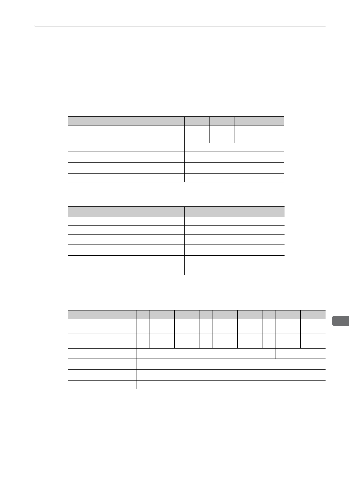
1.3.1 Ratings
Ratings of SERVOPACKs are as shown below.
(1) SGDV with Single-phase, 100-V Rating
SGDV (Single Phase, 100 V) R70 R90 2R1 2R8
Continuous Output Current [Arms] 0.66 0.91 2.1 2.8
Instantaneous Max. Output Current [Arms] 2.1 2.9 6.5 9.3
Regenerative Resistor * None or external
Main Circuit Power Supply
Control Power Supply
Overvoltage Category III
∗ Refer to 3.7 Connecting Regenerative Resistors for details.
Single-phase, 100 to 115 VAC , 50/60 Hz
Single-phase, 100 to 115 VAC , 50/60 Hz
(2) SGDV with Single-phase, 200-V Rating
SGDV (Single Phase, 200 V)
Continuous Output Current [Arms] 11.6
Instantaneous Max. Output Current [Arms] 28
Regenerative Resistor
*2
Main Circuit Power Supply
Control Power Supply
Built-in or external
Single-phase, 220 to 230 VAC , 50/60 Hz
Single-phase, 220 to 230 VAC , 50/60 Hz
Overvoltage Category III
∗1. The official model number is SGDV-120A21A008000.
∗2. Refer to 3.7 Connecting Regenerative Resistors for details.
120
*1
(3) SGDV with Three-phase, 200-V Rating
SGDV (Three Phase, 200 V) R70 R90 1R6 2R8 3R8 5R5 7R6 120 180 200 330 470 550 590 780
Continuous Output Current
[Arms]
Instantaneous Max. Output
Current [Arms]
Regenerative Resistor
Main Circuit Power Supply
Control Power Supply
Overvoltage Category III
0.66 0.91 1.6 2.8 3.8 5.5 7.6 11.6 18.5 19.6 32.9 46.9 54.7 58.6 78.0
2.1 2.9 5.8 9.3 11.0 16.9 17 28 42 56 84 110 130 140 170
*
None or external Built-in or external External
Three-phase, 200 to 230 VAC , 50/60 Hz
Single-phase, 200 to 230 VAC , 50/60 Hz
∗ Refer to 3.7 Connecting Regenerative Resistors for details.
1-3
Page 24

1 Outline
+10%
–15%
1.3.1 Ratings
(4) SGDV with Three-phase, 400-V Rating
SGDV (Three Phase, 400 V) 1R9 3R5 5R4 8R4 120 170 210 260 280 370
Continuous Output Current
[Arms]
Instantaneous Max. Output
Current [Arms]
Regenerative Resistor
*
1.9 3.5 5.4 8.4 11.9 16.5 20.8 25.7 28.1 37.2
5.5 8.5 14 20 28 42 55 65 70 85
Built-in or external External
Main Circuit Power Supply
Three-phase, 380 to 480 VAC , 50/60 Hz
Control Power Supply 24 VDC ±15%
Overvoltage Category III
∗ Refer to 3.7 Connecting Regenerative Resistors for details.
1-4
Page 25
1
Outline
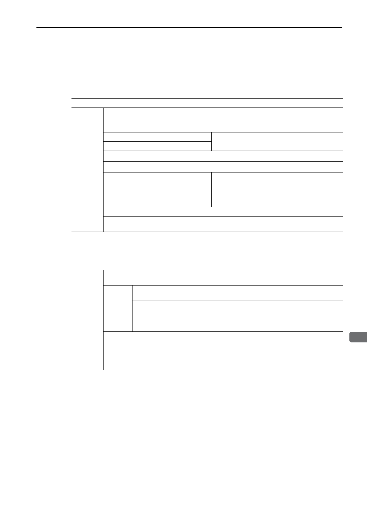
1.3.2 Basic Specifications
Basic specifications of SERVOPACKs are shown below.
Drive Method Sine-wave current drive with PWM control of IGBT
Feedback Encoder: 13-bit (incremental), 17-bit, 20-bit (incremental/absolute)
Surrounding Air Temperature
Storage Temperature -20°C to +85°C
Ambient Humidity 90% RH or less
Storage Humidity 90% RH or less
Vibration Resistance
Operating
Conditions
Shock Resistance
Protection Class IP10
Pollution Degree 2
0°C to +55°C
2
4.9 m/s
19.6 m/s
2
1.3 SERVOPACK Ratings and Specifications
With no freezing or condensation
An environment that satisfies the following conditions.
• Free of corrosive or flammable gases
• Free of exposure to water, oil, or chemicals
• Free of dust, salts, or iron dust
Altitude 1000 m or less
Others
Harmonized Standards
Mounting
Speed Control Range
Speed
Regu-
*1
Performance
lation
Torque Control
Tolerance
(Repeatability)
Soft Start Time
Setting
Load
Regulation
Volta ge
Regulation
Temperature
Regulation
Free of static electricity, strong electromagnetic fields, magnetic fields or
exposure to radioactivity
UL508C
EN50178, EN55011 group1 class A, EN61000-6-2, EN61800-3, EN61800-
5-1, EN954-1, IEC61508-1 to 4
Standard: Base-mounted
Optional: Rack-mounted or duct-ventilated
1:5000 (The lower limit of the speed control range must be lower than the
point at which the rated torque does not cause the servomotor to stop.)
0% to 100% load: ±0.01% max. (at rated speed)
Rated voltage ±10%: 0% (at rated speed)
25 ± 25
°C: ±0.1% max. (at rated speed)
±1%
0 to 10 s (Can be set individually for acceleration and deceleration.)
1-5
Page 26

1 Outline
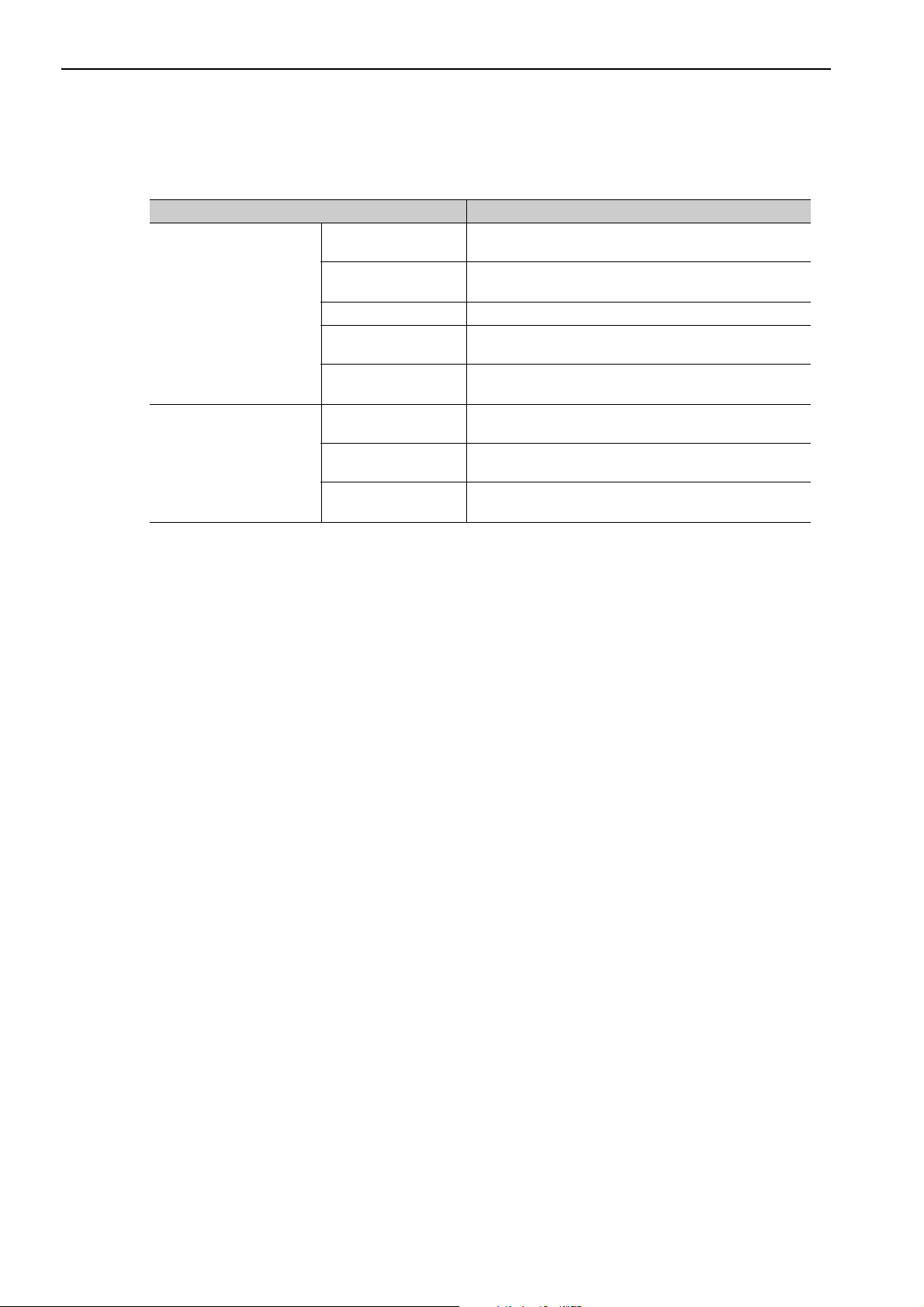
1.3.2 Basic Specifications
I/O
Signals
Communications
Function
LED Display Panel display (seven-segment), CHARGE, L1, L2, and CN indicators
MECHATROLINK-III
Communications Setting Switches
Analog Monitor (CN5)
Dynamic Brake (DB)
Regenerative Processing
Overtravel Prevention (OT)
Protective Function
Utility Function Gain adjustment, alarm history, JOG operation, origin search, and so on.
Encoder Output Pulse
Sequence
Input
Sequence
Output
RS422A
Communications
(CN3)
USB
Communications
(CN7)
Input
Signals
which can
be allocated
Fixed Output Servo alarm (ALM) output
Output
Signals
which can
be allocated
Interface
1:N
Communications
Axis
Address
Setting
Interface Personal computer (can be connected with SigmaWin+)
Communications
Standard
(cont’d)
Phase A, B, C: line driver
Encoder output pulse: any setting ratio (Refer to 4.4.5.)
Number of
Channels
Functions
Number of
Channels
Functions
Digital operator (JUSP-OP05A-1-E), personal computer (can be connected
with SigmaWin+)
N = Up to 15 stations possible at RS422A
Set by parameter
Complies with standard USB1.1. (12 Mbps)
Rotary Switch
(S1, S2)
DIP Switch (S3) Number of pins: Four pins (Refer to 4.1.1)
Number of points: 2
Output voltage: ± 10VDC (linearity effective range ± 8 V)
Resolution: 16 bits
Accuracy:
Max. output current: ± 10 mA
Settling time (
Activated when a servo alarm or overtravelling occurs or when the power
supply for the main circuit or servomotor is OFF.
Included
Dynamic brake stop, deceleration to a stop, or free run to a stop at P-OT or
N-OT
Overcurrent, overvoltage, insufficient voltage, overload, regeneration error,
and so on.
± 20 mV (Typ)
*2
7 ch
• Homing deceleration switch (/DEC)
• External latch (/EXT 1 to 3)
• Forward run prohibited (P-OT), reverse run prohibited
(N-OT)
• Forward external torque limit (/P-CL), reverse external
torque limit (/N-CL)
Signal allocations can be performed, and positive and
negative logic can be changed.
3 ch
• Positioning completion (/COIN)
• Speed coincidence detection (/V-CMP)
• Rotation detection (/TGON)
• Servo ready (/S-RDY)
• Torque limit detection (/CLT)
• Speed limit detection (/VLT)
• Brake (/BK)
• Warning (/WARN)
• Near (/NEAR)
Signal allocations can be performed, and positive and
negative logic can be changed.
Position: 16 positions × 2 (Refer to 4.1.1)
± 1%): 1.2 ms (Typ)
1-6
Page 27

1.3 SERVOPACK Ratings and Specifications
1
Outline
Speed regulation =
No-load motor speed Total load motor speed
Rated motor
speed
×
100%
-
Rotation
Input /HWBB1, /HWBB2: Baseblock signal for power module
Safety Function
Output EDM1: Monitoring status of internal safety circuit (fixed output)
*3
Standards
EN954 Category 3, IEC61508 SIL2
Option Module Fully-closed module, safety module
∗1. Speed regulation by load regulation is defined as follows:
∗2. Refer to 1.3.1 Ratings for details on regenerative resistors.
∗3. Perform risk assessment for the system and be sure that the safety requirements are fulfilled.
(cont’d)
1-7
Page 28
1 Outline
1.3.3 MECHATROLINK-III Function Specifications
1.3.3 MECHATROLINK-III Function Specifications
The following table shows the specifications of MECHATROLINK-III.
Function Specifications
MECHATROLINK-III
Communication
Reference Method
Communication Protocol
Station Address
Baud Rate 100 Mpbs
Transmission Cycle
Number of Transmission Bytes
Control Method
Reference Input
Profile
MECHATROLINK-III
03H to EFH (Max. number of stations: 62)
Use the rotary switches S1 and S2 to set the station address.
125 μs, 250 μs, 500 μs, 750 μs, and 1.0 ms to 4.0 ms (increments of 0.5 ms)
16, 32, or 48 bytes per station
Use the DIP switch S3 to select the number of words.
Position, speed, or torque control with MECHATROLINKIII communication
MECHATROLINK commands (sequence, motion, data setting/reference, monitoring, or adjustment)
MECHATROLINK-III standard servo profile
MECHATROLINK-II-compatible profile
1-8
Page 29
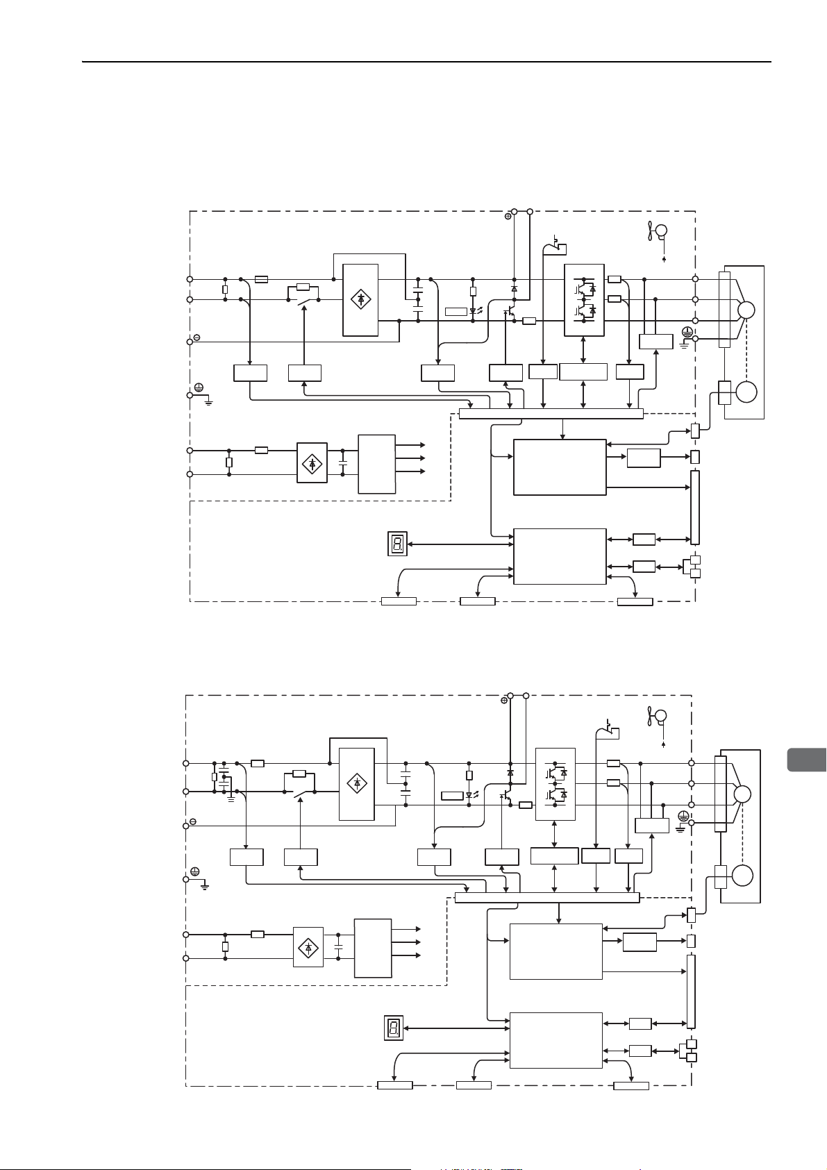
1.4 SERVOPACK Internal Block Diagrams
1
Outline
L1
B1/ B2
L2
L1C
L2C
U
V
W
CHARGE
M
ENC
Control power
supply
Main circuit
power supply
Control
power
supply
±12 V
+5 V
+17 V
Current
sensor
Dynamic
brake circuit
Servomotor
Gate
drive
Voltage
sensor
Voltage
sensor
Varistor
Varistor
Gate drive
overcurrent
protector
Temperature
sensor
Relay
drive
+
12 V
Fan
+
–
+
–
+
–
CN3 CN7 CN8
CN2
I/O
I/F
CN1
CN6A
CN6B
CN5
MECHATROLINK-III
communications
CPU
(Position/speed
calculation, etc.)
Panel display
Digital operator
Personal
computer
Signal for safety fuction
Encoder output
pulse
I/O signal
Analog monitor
output
ASIC
(PWM control, etc.)
Analog
voltage
converter
M-III
M-III
1.4 SERVOPACK Internal Block Diagrams
1.4.1 Single-phase 100 V, SGDV-R70F21A, -R90F21A, -2R1F21A Models
1.4.2 Single-phase 100 V, SGDV-2R8F21A Model
Varistor
Main circuit
power supply
Control power
supply
L1
L2
L1C
Varistor
Voltage
sensor
Relay
drive
L2C
Control
+
power
–
supply
Panel display
Digital operator
+
–
+
–
CHARGE
Voltage
sensor
±12 V
+5 V
+17 V
CN3 CN7 CN8
Personal
computer
B1/ B2
Gate
drive
Gate drive
overcurrent
protector
(PWM control, etc.)
(Position/speed
calculation, etc.)
ASIC
CPU
Temperature
sensor
Fan
+12 V
Dynamic
brake circuit
Current
sensor
Analog
voltage
converter
I/O
I/F
Signal for safety fuction
W
CN2
CN5
CN1
CN6A
CN6B
U
V
Analog monitor
output
Encoder output
pulse
I/O signal
MECHATROLINK-III
communications
Servomotor
M
ENC
1-9
Page 30
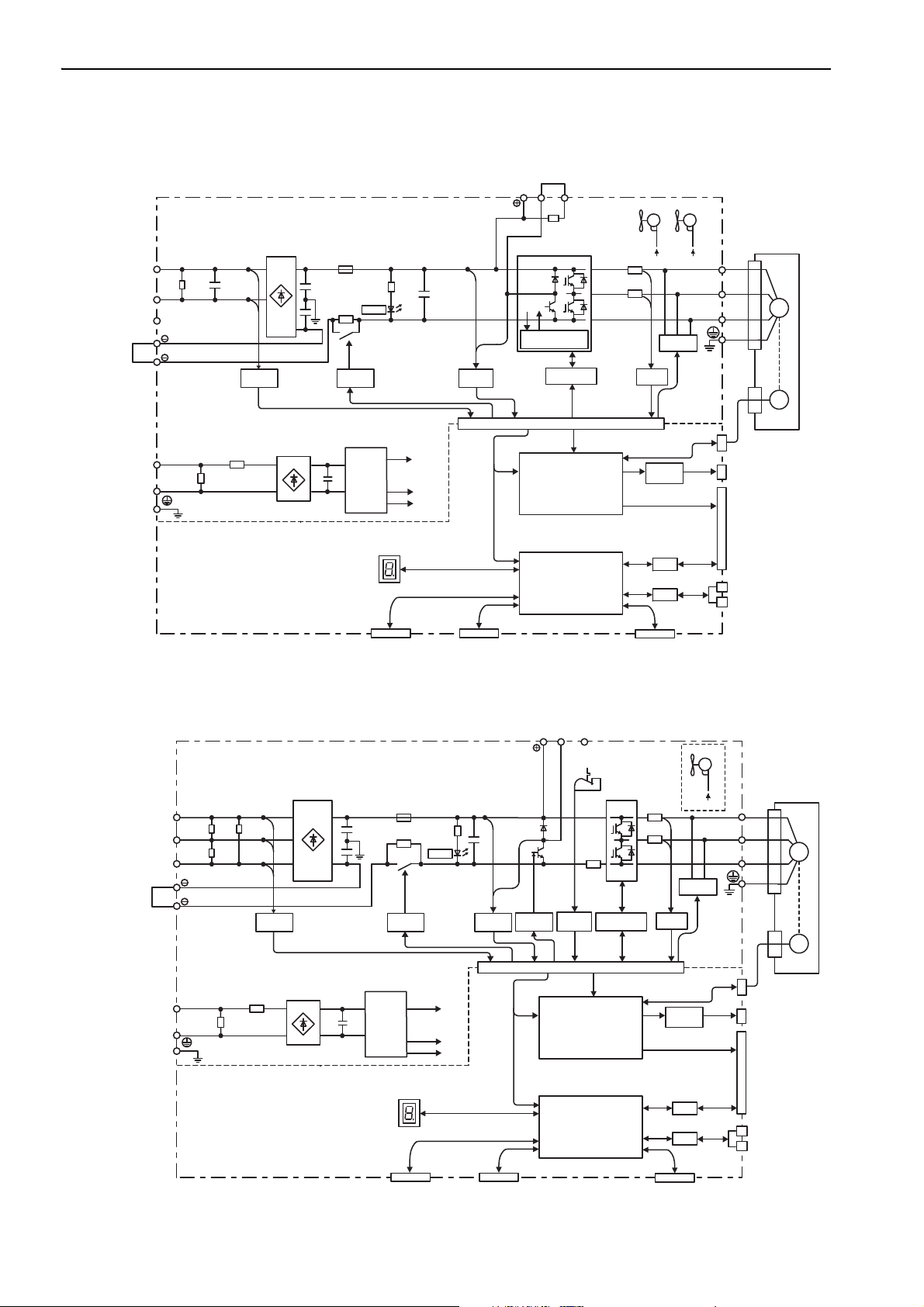
1 Outline
L1
B1/ B2 B3
L2
1
2
L1C
L2C
U
V
W
ENC
M
L3
CHARGE
+15V × 4
±12 V
+5 V
Current
sensor
Dynamic
brake circuit
Servomotor
Gate drive
Voltage
sensor
Overheat protector,
overcurrent protector
Voltage
sensor
Varistor
Varistor
Relay
drive
Fan 2 Fan 1
Control
power
supply
±12 V ±12 V
+
–
+
–
Main circuit
power supply
Control power
supply
CN3 CN7 CN8
CN2
I/O
I/F
CN1
CN6A
CN6B
CN5
MECHATROLINK-III
communications
CPU
(Position/speed
calculation, etc.)
Panel display
Digital operator
Personal
computer
Signal for safety fuction
Encoder output
pulse
Analog monitor
output
ASIC
(PWM control, etc.)
Analog
voltage
converter
I/O signal
64
L1
B1/ B2 B3
L2
L3
1
2
L1C
L2C
U
V
W
ENC
M
CHARGE
+17 V
±12 V
+5 V
Current
sensor
Dynamic
brake circuit
Servomotor
*
Gate
drive
Voltage
sensor
Voltage
sensor
Varistor
Varistor
Gate drive
overcurrent
protector
Temperature
sensor
Relay
drive
Control
power
supply
+
–
+
–
Main circuit
power supply
Control power
supply
Fan
+12 V
CN3 CN7 CN8
CN2
I/O
I/F
CN1
CN6A
CN6B
CN5
MECHATROLINK-III
communications
CPU
(Position/speed
calculation, etc.)
Panel display
Digital operator
Personal
computer
Signal for safety fuction
Encoder output
pulse
Analog monitor
output
ASIC
(PWM control, etc.)
Analog
voltage
converter
I/O signal
M-III
1.4.3 Single-phase 200 V, SGDV-120A21A008000 Model
1.4.3 Single-phase 200 V, SGDV-120A21A008000 Model
1.4.4 Three-phase 200 V, SGDV-R70A21, -R90A21, -1R6A21 Models
1-10
∗ The following SERVOPACKs do not have cooling fans: SGDV-B.
Page 31

1
Outline
1.4.5 Three-phase 200 V, SGDV-2R8A21 Model
L1
B1/ B2 B3
L2
L3
1
2
L1C
L2C
U
V
W
ENC
M
CHARGE
+17 V
±12 V
+5 V
Current
sensor
Dynamic
brake circuit
Servomotor
Gate
drive
Voltage
sensor
Voltage
sensor
Varistor
Varistor
Gate drive
overcurrent
protector
Temperature
sensor
Relay
drive
Control
power
supply
+
–
+
–
Main circuit
power supply
Control power
supply
CN3 CN7 CN8
CN2
I/O
I/F
CN1
CN6A
CN6B
CN5
MECHATROLINK-III
communications
CPU
(Position/speed
calculation, etc.)
Panel display
Digital operator
Personal
computer
Signal for safety fuction
Encoder output
pulse
Analog monitor
output
ASIC
(PWM control, etc.)
Analog
voltage
converter
I/O signal
Fan
+12 V
*
M-III
L1
B1/ B2 B3
L2
L3
1
2
L1C
L2C
U
V
W
ENC
M
CHARGE
+17 V
±12 V
+5 V
Current
sensor
Dynamic
brake circuit
Servomotor
Gate
drive
Voltage
sensor
Voltage
sensor
Varistor
Varistor
Gate drive
overcurrent
protector
Temperature
sensor
Relay
drive
Fan
Control
power
supply
±12 V
+
–
+
–
Main circuit
power supply
Control power
supply
CN3 CN7 CN8
CN2
I/O
I/F
CN1
CN6A
CN6B
CN5
MECHATROLINK-III
communications
CPU
(Position/speed
calculation, etc.)
Panel display
Digital operator
Personal
computer
Signal for safety fuction
Encoder output
pulse
Analog monitor
output
ASIC
(PWM control, etc.)
Analog
voltage
converter
I/O signal
M-III
1.4 SERVOPACK Internal Block Diagrams
∗ The following SERVOPACKs do not have cooling fans: SGDV-B.
1.4.6 Three-phase 200 V, SGDV-3R8A21A, -5R5A21A, -7R6A21A Models
1-11
Page 32

1 Outline
L1
B1/ B2 B3
L2
L3
1
2
L1C
L2C
U
V
W
ENC
M
CHARGE
+15 V × 4
±12 V
+5 V
Current
sensor
Dynamic
brake circuit
Servomotor
Gate drive
Overheat protector,
overcurrent protector
Voltage
sensor
Voltage
sensor
Varistor
Varistor
Relay
drive
Fan
Control
power
supply
±12 V
+
–
+
–
Main circuit
power supply
Control power
supply
CN3 CN7 CN8
CN2
I/O
I/F
CN1
CN6A
CN6B
CN5
MECHATROLINK-III
communications
CPU
(Position/speed
calculation, etc.)
Panel display
Digital operator
Personal
computer
Signal for safety fuction
Encoder output
pulse
Analog monitor
output
ASIC
(PWM control, etc.)
Analog
voltage
converter
I/O signal
M-III
L1
B1/ B2 B3
L2
L3
1
2
L1C
L2C
U
V
W
ENC
M
CHARGE
+
–
+15 V × 4
±12 V
+5 V
Current
sensor
Dynamic
brake circuit
Servomotor
Gate drive
Voltage
sensor
Overheat protector,
overcurrent protector
Voltage
sensor
Varistor
Varistor
Relay
drive
Fan 2 Fan 1
Control
power
supply
±12 V ±12 V
+
–
Main circuit
power supply
Control power
supply
CN3 CN7 CN8
CN2
I/O
I/F
CN1
CN6A
CN6B
CN5
MECHATROLINK-III
communications
CPU
(Position/speed
calculation, etc.)
Panel display
Digital operator
Personal
computer
Signal for safety fuction
Encoder output
pulse
Analog monitor
output
ASIC
(PWM control, etc.)
Analog
voltage
converter
I/O signal
M-III
1.4.7 Three-phase 200 V, SGDV-120A21A Model
1.4.7 Three-phase 200 V, SGDV-120A21A Model
1.4.8 Three-phase 200 V, SGDV-180A21A, -200A21A Models
1-12
Page 33

1
Outline
1.4.9 Three-phase 200 V, SGDV-330A21A Model
L1
B1/ B2 B3
L2
L3
1
2
L1C
L2C
U
V
W
ENC
M
CHARGE
Varistor
+
–
+
–
+15 V × 4
±12 V
+5 V
Current
sensor
Dynamic
brake circuit
Servomotor
Gate drive
Voltage
sensor
Voltage
sensor
Varistor
Temperature
sensor
Thyristor
drive
Fan 2 Fan 1
Overheat protector,
overcurrent protector
Control
power
supply
±12 V ±12 V
Main circuit
power supply
Control power
supply
I/O signal
CN3 CN7 CN8
CN2
I/O
I/F
CN1
CN6A
CN6B
CN5
MECHATROLINK-III
communications
CPU
(Position/speed
calculation, etc.)
Panel display
Digital operator
Personal
computer
Signal for safety fuction
Encoder output
pulse
Analog monitor
output
ASIC
(PWM control, etc.)
Analog
voltage
converter
M-III
M-III
1.4 SERVOPACK Internal Block Diagrams
1.4.10 Three-phase 200 V, SGDV-470A21A, -550A21A Models
B1/ B2
Varistor
L1
Main circuit
power supply
Control power
supply
L2
L3
L1C
L2C
Varistor
Voltage
sensor
Thyristor
drive
+
–
Control
power
supply
Panel display
CN3 CN7 CN8
Digital operator
+
–
CHARGE
Voltage
sensor
+15 V × 4
+5 V
12 V
±
Personal
computer
overcurrent protector
Overheat protector,
Gate
drive
ASIC
(PWM control, etc.)
CPU
(Position/speed
calculation, etc.)
Temperature
sensor
Fan 1 Fan 2 Fan 3
±
12 V ±12 V ±12 V
Dynamic
brake circuit
Current
sensor
CN2
CN5
Analog
voltage
converter
I/O
CN6A
I/F
CN6B
Signal for safety fuction
CN1
Servomotor
U
V
W
M
ENC
Analog monitor
output
Encoder output
pulse
I/O signal
MECHATROLINK-III
communications
1-13
Page 34

1 Outline
64
M-III
1.4.11 Three-phase 200 V SGDV-590A21A, -780A21A Models
1.4.11 Three-phase 200 V SGDV-590A21A, -780A21A Models
Main circuit
power supply
Control power
supply
L1
L2
L3
L1C
L2C
Varistor
Varistor
Voltage
sensor
Thyristor
drive
Control
+
power
–
supply
B1/ B2
+
–
CHARGE
Overheat protector,
overcurrent protector
Gate
drive
ASIC
CPU
Temperature
sensor
Panel display
+15 V × 4
+5 V
12 V
±
Voltage
sensor
(PWM control, etc.)
(Position/speed
calculation, etc.)
CN3 CN7 CN8
Digital operator
Personal
computer
Fan 1 Fan 2 Fan 3
±
12 V ±12 V ±12 V
Dynamic
brake circuit
Current
sensor
CN2
CN5
Analog
voltage
converter
CN1
I/O
CN6A
I/F
CN6B
Signal for safety fuction
Servomotor
U
V
M
W
ENC
Analog monitor
output
Encoder output
pulse
I/O signal
MECHATROLINK-III
communications
1.4.12 Three-phase 400 V, SGDV-1R9D21A, -3R5D21A, -5R4D21A Models
Main circuit
power supply
Control power
supply
(The 24 VDC
power supply is
not included.)
L1
L2
L3
1
2
+24 V
0 V
Varistor
Voltage
sensor
+
–
Relay
drive
Control
power
supply
Panel display
Digital operator
B1/ B2 B3
+
–
+
–
+15 V × 4
+5 V
±12 V
CHARGE
Voltage
sensor
Overheat protector,
overcurrent protector
Gate
drive
ASIC
(PWM control, etc.)
CPU
(Position/speed
calculation, etc.)
CN3 CN7 CN8
Personal
computer
Signal for safety fuction
Current
sensor
Analog
voltage
converter
Fan
±12 V
Dynamic
brake circuit
I/O
I/F
U
V
W
CN2
CN5
CN1
CN6A
CN6B
Servomotor
M
ENC
Analog monitor
output
Encoder output
pulse
I/O signal
MECHATROLINK-III
communications
1-14
Page 35

1.4 SERVOPACK Internal Block Diagrams
1
Outline
L1
B1/ B2 B3
L2
L3
1
2
+24 V
0 V
U
V
W
ENC
M
CHARGE
+15 V × 4
+5 V
±12 V
+
–
+
–
Current
sensor
Servomotor
Gate
drive
Voltage
sensor
Voltage
sensor
Relay
drive
Control
power
supply
Overheat protector,
overcurrent protector
Dynamic
brake circuit
Varistor
±12 V ±12 V
Fan 1 Fan 2
+
–
Main circuit
power supply
Control power
supply
(The 24 VDC
power supply is
not included.)
CN3 CN7 CN8
CN2
I/O
I/F
CN1
CN6A
CN6B
CN5
MECHATROLINK-III
communications
CPU
(Position/speed
calculation, etc.)
Panel display
Digital operator
Personal
computer
Signal for safety fuction
Encoder output
pulse
Analog monitor
output
ASIC
(PWM control, etc.)
Analog
voltage
converter
I/O signal
M-III
M-III
1.4.13 Three-phase 400 V, SGDV-8R4D21A, -120D21A Models
1.4.14 Three-phase 400 V, SGDV-170D21A Model
Varistor
Main circuit
power supply
Control power
supply
(The 24 VDC
power supply is
not included.)
L1
L2
L3
1
2
+24 V
0 V
Voltage
sensor
+
–
Relay
drive
Control
power
supply
Panel display
Digital operator
+
–
+
CHARGE
–
+15 V × 4
+5 V
±12 V
CN3 CN7 CN8
Personal
computer
B1/ B2 B3
Voltage
sensor
(PWM control, etc.)
(Position/speed
calculation, etc.)
Overheat protector,
overcurrent protector
Gate
drive
ASIC
CPU
Fan
Dynamic
brake circuit
Current
sensor
Analog
voltage
converter
I/O
I/F
Signal for safety fuction
±12 V
CN6A
CN6B
U
V
W
CN2
CN5
CN1
Servomotor
M
ENC
Analog monitor
output
Encoder output
pulse
I/O signal
MECHATROLINK-III
communications
1-15
Page 36

1 Outline
M-III
64
1.4.15 Three-phase 400 V, SGDV-210D21A, -260D21A Models
1.4.15 Three-phase 400 V, SGDV-210D21A, -260D21A Models
Main circuit
power supply
Control power
supply
(The 24 VDC
power supply is
not included.)
L1
L2
L3
1
2
+24 V
0 V
Varistor
Voltage
sensor
+
–
B1/ B2
+
–
+
CHARGE
–
Overheat protector,
overcurrent protector
Relay
drive
Control
power
supply
Panel display
+15 V × 4
+5 V
±12 V
Voltage
sensor
(PWM control, etc.)
Gate
drive
ASIC
CPU
(Position/speed
calculation, etc.)
CN3 CN7 CN8
Digital operator
Personal
computer
Fan 1 Fan 2 Fan 3
+24 V +24 V +24 V
Dynamic
brake circuit
Current
sensor
CN2
CN5
Analog
voltage
converter
I/O
CN6A
I/F
CN6B
Signal for safety fuction
CN1
Servomotor
U
V
M
W
ENC
Analog monitor
output
Encoder output
pulse
I/O signal
MECHATROLINK-III
communications
1.4.16 Three-phase 400 V, SGDV-280D21A, -370D21A Models
B1/ B2
Varistor
Main circuit
power supply
Control power
supply
(The 24 VDC
power supply is
not included.)
L1
L2
L3
1
2
+24 V
0 V
Voltage
sensor
+
–
Control
power
supply
Panel display
+
–
+
CHARGE
–
Overheat protector,
overcurrent protector
Thyristor
drive
+15 V × 4
+5 V
±12 V
Voltage
sensor
Gate
drive
ASIC
(PWM control, etc.)
CPU
(Position/speed
calculation, etc.)
CN3 CN7 CN8
Digital operator
Personal
computer
Fan 1 Fan 2 Fan 3
+24 V +24 V +24 V
Dynamic
brake circuit
Current
sensor
CN2
CN5
Analog
voltage
converter
I/O
CN6A
I/F
CN6B
Signal for safety fuction
CN1
Servomotor
U
V
W
M
ENC
Analog monitor
output
Encoder output
pulse
I/O signal
MECHATROLINK-III
communications
1-16
Page 37

1.5 Examples of Servo System Configurations
1
Outline
Servomotor main
circuit cable
Encoder cable
Battery case
Brake power supply
*1
Magnetic contactor
Regenerative
resistor
*2
Noise filter
Molded-case
circuit breaker
(MCCB)
Magnetic
contactor
I/O signal cable
SGDV-F21A
SERVOPACK
SGMJV/SGMAV/SGMPS/SGMCS
Servomotor
Power supply
Single-phase 100 VAC
R T
Protects the power line
by shutting the circuit
OFF when overcurrent
is detected.
Eliminates external
noise from the power
line.
Used for a servomotor with
a brake.
Turns the servo
ON and OFF.
Install a surge
absorber.
Turns the brake power supply
ON and OFF.
Install a surge absorber.
(when an absolute encoder
is used.)
Personal
computer
Connection cable
for personal computer
Digital
operator
When not using the safety function,
use the SERVOPACK with the safety
function’s jumper connector
(JZSP-CVH05-E, provided as an accessory)
inserted
When using the safety function,
insert a connection cable
specially for the safety function.
Safety function
devices
Connection cable
for digital operator
100 VAC
Host controller
Connect to the
MECHATROLINK-III
100V
64
1.5 Examples of Servo System Configurations
This section describes examples of basic servo system configuration.
1.5.1 Connecting to SGDV-F21A SERVOPACK
∗1. Use a 24-VDC power supply. (Not included.)
∗2. Before connecting an external regenerative resistor to the SERVOPACK, refer to 3.7 Connecting Regenerative Resis-
tors.
1-17
Page 38

1 Outline
Servomotor main
circuit cable
Encoder cable
Battery case
Brake power supply
∗1
Magnetic contactor
∗2
Noise filter
Molded-case
circuit breaker
(MCCB)
Magnetic contactor
I/O signal cable
SGDV-A21
SERVOPACK
SGMJV/SGMAV/SGMPS/
SGMGV/SGMSV/SGMCS
Servomotor
Power supply
Three-phase 200 VAC
R S T
Protects the power
line by shutting the
circuit OFF when
overcurrent is
detected
Eliminates external
noise from the
power line.
Used for a servomotor
with a brake.
Turns the servo
ON and OFF.
Install a surge
absorber.
Turns the brake power supply
ON and OFF.
Install a surge absorber.
(when an absolute
encoder is used.)
Personal
computer
Connection cable
for personal computer
Digital
operator
When not using the safety function, use
the SERVOPACK with the safety
function’s jumper connector (JZSP-CVH05-E,
provided as an accessory) inserted.
When using the safety function, insert
a connection cable specifically for
the safety function.
Safety function
devices
Connection cable
for digital operator
200 VAC
Host controller
Regenerative
resistor
Connect to the
MECHATROLINK-III
64
1.5.2 Connecting to SGDV-A21 SERVOPACK
1.5.2 Connecting to SGDV-A21 SERVOPACK
(1) Using a Three-phase, 200-V Power Supply
1-18
∗1. Use a 24-VDC power supply. (Not included.)
If using a 90-VDC power supply for a brake, however, use one of the following power supplies.
• For 200-V input voltage: LPSE-2H01-E
• For 100-V input voltage: LPDE-1H01-E
For details, refer to
∗2. Before connecting an external regenerative resistor to the SERVOPACK, refer to 3.7 Connecting Regenerative Resis-
tors.
Σ
-V Series Product Catalog (No.: KAEP S800000 42).
Page 39

1.5 Examples of Servo System Configurations
1
Outline
Brake power supply
∗
1
Servomotor main
circuit cable
Encoder cable
Battery case
Magnetic contactor
Regenerative
resistor
Noise filter
Molded-case
circuit breaker
(MCCB)
Magnetic
contactor
Host controller
When not using the safety function,
use the SERVOPACK with the safety
function’s jumper connector
(JZSP-CVH05-E, provided as an
accessory) inserted.
When using the safety function,
insert a connection cable specifically
for the safety function.
Safety function
devices
I/O signal cable
SGDV-
A21
SERVOPACK
SGMJV/SGMAV/SGMPS/SGMCS
Servomotor
Power supply
Single-phase 200 VAC
R T
Protects the power
line by shutting the
circuit OFF when
overcurrent is
detected.
Eliminates
external noise from
the power line.
Used for a servomotor
with a brake.
Turns the servo
ON and OFF.
Install a surge
absorber.
Turns the brake power supply
ON and OFF.
Install a surge absorber.
(when an absolute
encoder is used.)
Connection cable
for digital operator
Connection cable
for personal computer
Digital
operator
Personal
computer
∗
2
200 VAC
Connect to the
MECHATROLINK-III
64
(2) Using a Single-phase, 200-V Power Supply
The Σ-V Series 200 V SERVOPACK generally specifies a three-phase power input but some models can be
used with a single-phase 200 V power supply. Refer to 3.1.3 Using the SERVOPACK with Single-phase, 200 V
Power Input for details.
∗1. Use a 24-VDC power supply. (Not included.)
∗2. Before connecting an external regenerative resistor to the SERVOPACK, refer to 3.7 Connecting Regenerative Resis-
tors.
1-19
Page 40

1 Outline
64
1.5.3 Connecting to SGDV-D21A SERVOPACK
1.5.3 Connecting to SGDV-D21A SERVOPACK
Power supply
Three-phase 400 VAC
R S T
Molded-case
circuit breaker
(MCCB)
Protects the power
line by shutting
the circuit OFF
when overcurrent
is detected.
Noise filter
Eliminates external
noise from the
power line.
Magnetic
contactor
Turns the servo
ON and OFF.
Install a surge
absorber.
100/200 VAC
DC power
supply (24 V)
SGDV-D21A
SERVOPACK
*1
Connection cable
for digital operator
Connection cable
for personal computer
I/O signal cable
Connect to the
MECHATROLINK-III
Digital
operator
Personal
computer
Host controller
Regenerative
*2
resistor
Brake power
*3
UWRRN[
Used for a servomotor
with a 90 V brake.
Magnetic contactor
Turns the brake power
supply ON and OFF.
Install a surge absorber.
Battery case
(when an absolute
encoder is used.)
Servomotor main
circuit cable
SGMGV/SGMSV
Servomotor
When not using the safety function,
use the SERVOPACK with the safety
function’s jumper connector
(JZSP-CVH05-E, provided as an
accessory) inserted.
When using the safety function,
insert a connection cable specifically
for the safety function.
Safety function
devices
Encoder cable
1-20
∗1. Use a 24-VDC power supply with double insulation or reinforced insulation. (The 24-VDC power supply is not
included.) Do not use the same 24-VDC power supply for the brakes.
∗2. Before connecting an external regenerative resistor to the SERVOPACK, refer to 3.7 Connecting Regenerative Resis-
tors.
∗3. Use a 24-VDC power supply for a brake. (Not included.)
If using a 90-VDC power supply for a brake, however, use one of the following power supplies.
• For 200-V input voltage: LPSE-2H01-E
• For 100-V input voltage: LPDE-1H01-E
For details, refer to Σ-V Series Product Catalog (No.: KAEP S800000 42).
Page 41

1
Outline
1.6 SERVOPACK Model Designation
SGDV
Series
SGDV Σ-V Series
1st + 2nd + 3rd digits: Current
Voltage Code
Max. Allowable
Motor Capacity
(kW)
100 V
R70 0.05
R90 0.1
2R1 0.2
2R8 0.4
200 V
R70
*1
0.05
R90
*1
0.1
1R6
*1
0.2
2R8
*1
0.4
3R8 0.5
5R5
*1
0.75
7R6 1
120
*2
1.5
180 2
200 3
330 5
470
*3
6
550
*3
7.5
590
*3
11
780
*3
15
400 V
1R9 0.5
3R5 1
5R4 1.5
8R4 2
120 3
170 5
210
*3
6
260
*3
7.5
280
*3
11
370
*3
15
4th digit: Voltage
Code Voltage
F 100 V
A 200 V
D 400 V
5th + 6th digits: Interface Specifications
Code Interface
01
Analog voltage and pulse train reference, rotational servomotor
05
Analog voltage and pulse train reference, linear servomotor
11
MECHATROLINK-II communications
reference, rotational servomotor
15
MECHATROLINK-II communications
reference, linear servomotor
21
MECHATROLINK-III communications
reference, rotational servomotor
25
MECHATROLINK-III communications
reference, linear servomotor
11th + 12th digits: Software Specifi-
cation
Code Specification
00 Standard
–
7th digit: Design
Revision Order
1st + 2nd +
3rd digits
4th
digit
5th + 6th
digits
7th
digit
2R8 A
21
A
8th + 9th +
10th digits
000
8th + 9th + 10th digits: Hardware Specifications
Code Specifications
000 Base-mounted (standard)
001
Rack-mounted
*3
002 Varnished
003
Rack-mounted
*3
and Varnished
008
Single-phase, 200-V Power Supply
(SGDV-120A1A008000)
020
Dynamic brake (DB)
*4
11th + 12th
digits
00
13th
digit
0
13th digit: Parameter Specification
Code Specification
0 Standard
This section shows SERVOPACK model designation.
1.6 SERVOPACK Model Designation
∗1. These amplifiers can be powered with single or three-phase.
∗2. SGDV-120A1A008000, a special version of the 1.5 kW amplifier can be used for single-phase operation.
∗3. SGDV-470A, -550A, -590A, -780A, -210D, -260D, -280D, and -370D are duct-ventilated types.
∗4. A resistor for the dynamic brake is not included. An external resistor for the dynamic brake can only be used with
400-V SERVOPACKs.
Note: If the option codes digits 8 to 13 are all zeros, they are omitted.
1-21
Page 42

1 Outline
1.7 Inspection and Maintenance
This section describes the inspection and maintenance of SERVOPACK.
(1) SERVOPACK Inspection
For inspection and maintenance of the SERVOPACK, follow the inspection procedures in the following table
at least once every year. Other routine inspections are not required.
Item Frequency Procedure Comments
Exterior
At least once a year
Loose Screws
(2) SERVOPACK’s Parts Replacement Schedule
The following electric or electronic parts are subject to mechanical wear or deterioration over time. To avoid
failure, replace these parts at the frequency indicated.
Refer to the standard replacement period in the following table and contact your Yaskawa representative.
After an examination of the part in question, we will determine whether the parts should be replaced or not.
Check for dust, dirt, and oil
on the surfaces.
Check for loose terminal
block and connector
screws.
Clean with compressed air.
Tighten any loose screws.
The parameters of any SERVOPACKs overhauled by Yaskawa are reset to the factory
settings before shipping. Be sure to confirm that the parameters are properly set before
starting operation.
Part
Cooling Fan 4 to 5 years
Smoothing Capacitor 7 to 8 years
Other Aluminum Electrolytic
Capacitor
Relays –
Fuses 10 years
Standard Replacement
Period
5 years
Operating Conditions
• Surrounding Air Temperature: Annual average of
30°C
• Load Factor: 80% max.
• Operation Rate: 20 hours/day max.
1-22
Page 43

2
Panel Display and Operation of Digital Operator
2
Panel Display and
Operation of Digital Operator
2.1 Panel Display . . . . . . . . . . . . . . . . . . . . . . . . . . . . . . . . . . . . . . . . . . . . . . 2-2
2.1.1 Status Display . . . . . . . . . . . . . . . . . . . . . . . . . . . . . . . . . . . . . . . . . . . . . . . . . . . . . . . 2-2
2.1.2 Alarm and Warning Display . . . . . . . . . . . . . . . . . . . . . . . . . . . . . . . . . . . . . . . . . . . . . 2-2
2.1.3 Hard Wire Base Block Display . . . . . . . . . . . . . . . . . . . . . . . . . . . . . . . . . . . . . . . . . . 2-2
2.1.4 Overtravel Display . . . . . . . . . . . . . . . . . . . . . . . . . . . . . . . . . . . . . . . . . . . . . . . . . . . .2-2
2.2 Operation of Digital Operator . . . . . . . . . . . . . . . . . . . . . . . . . . . . . . . . . . 2-3
2.3 Utility Functions (Fn) . . . . . . . . . . . . . . . . . . . . . . . . . . . . . . . . . . . .2-3
2.4 Parameters (Pn) . . . . . . . . . . . . . . . . . . . . . . . . . . . . . . . . . . . . . . .2-4
2.4.1 Parameter Classification . . . . . . . . . . . . . . . . . . . . . . . . . . . . . . . . . . . . . . . . . . . . . . . 2-4
2.4.2 Notation for Parameters . . . . . . . . . . . . . . . . . . . . . . . . . . . . . . . . . . . . . . . . . . . . . . . 2-4
2.4.3 Setting Parameters . . . . . . . . . . . . . . . . . . . . . . . . . . . . . . . . . . . . . . . . . . . . . . . . . . . 2-5
2.5 Monitor Displays (Un) . . . . . . . . . . . . . . . . . . . . . . . . . . . . . . . . . . .2-7
2-1
Page 44

2 Panel Display and Operation of Digital Operator
MECHA
Status
Display
Unlit Unlit Unlit Unlit
MECHA
46and64
2.1.1 Status Display
2.1 Panel Display
The servo status can be checked on the panel display of the SERVOPACK.
Also, if an alarm or warning occurs, its alarm or warning number is displayed.
2.1.1 Status Display
The display shows the following status.
Display Meaning
Rotation Detection (/TGON)
Lights if motor speed exceeds the value set in Pn502. (Factory setting: 20 min
Baseblock
Lights for baseblock (Servomotor power OFF).
Reference Input
Lights when a reference is being input.
Control Power Supply ON
Lights when the control power is being supplied.
2.1.2 Alarm and Warning Display
If an alarm or warning occurs, the display will change in the following order.
Example: Alarm A.E60
Status
Display
Unlit Unlit Unlit Unlit Unlit
-1
)
2-2
2.1.3 Hard Wire Base Block Display
If a hard wire base block (HWBB) occurs, the display will change in the following order.
2.1.4 Overtravel Display
If overtravelling occurs, the display will change in the following order.
1
Overtravel at forward rotation (P-OT)
Current
status
2
Overtravel at reverse rotation (N-OT)
Current
status
3
Overtravel at forward/reverse rotation
Current
status
Page 45

2
Panel Display and Operation of Digital Operator
2.2 Operation of Digital Operator
BB − FUNCTION−
Fn002:JOG
Fn003:Z− Search
Fn004:Program JOG
Fn005:Prm Init
BB − Z − Search−
Un000=0 00000
Un002=0 00000
Un003=0 0000000774
Un00D=0 0000000000
Parameter
key
key
Pn000
n.0
CCW CW
n.1
CW CCW
BB − Z − Search−
Un000=0 00000
Un002=0 00000
Un003=0 0000000000
Un00
D=0 0000001D58
Operation examples of utility functions (Fn), parameters (Pn) and monitor displays (Un)
when using a digital operator are described in this chapter.
Operations can be also performed with SigmaWin+.
2.2 Operation of Digital Operator
For more information on the usage of the digital operator, refer to
Digital Operator (No.: SIEP S800000 55).
2.3 Utility Functions (Fn)
The utility functions are related to the setup and adjustment of the SERVOPACK.
The digital operator shows numbers beginning with Fn.
The following table outlines the procedures necessary for an origin search (Fn003).
Step Display after Operation Keys Operation
1
2
RUN − Z − Search−
Un000=0 00000
3
Un002=0 00000
Un003=0 0000000774
Un00
D=0 0000000000
Σ
-V Series USER’S MANUAL Operation of
Press the Key to view the main menu for the utility function.
Use the or Key to move through the list and
select Fn003.
Press the Key. The display changes to the Fn003
execution display.
Press the Key.
The status display changes from "BB" to "RUN", and
the servomotor power turns ON.
Note: If the servomotor is already at the zero position,
"-Complete-" is displayed.
Pressing the Key will rotate the servomotor in the
forward direction. Pressing the Key will rotate the
servomotor in the reverse direction. The rotation direction of the servomotor changes according to the setting
of Pn000.0 as shown in the following table.
RUN − Complete−
Un000=0 00000
4
Un002=0 00000
Un003=0 0000000000
Un00D=0 0000001D58
Note: Direction when viewed from the load of the ser-
vomotor.
Press the or Key until the servomotor stops.
If the origin search completed normally, "-Complete-"
is displayed on the right top on the screen.
When the origin search is completed, press the
Key.
5
The status display changes from "RUN" to "BB", and
the servomotor turns OFF. The display "-Complete-"
changes to "-Z-Search-."
BB − FUNCTION−
Fn002:JOG
6
Fn003:Z− Search
Fn004:Program JOG
Fn005:Prm Init
Press the Key.
The display returns to the main menu of the utility
function.
7 To enable the change in the setting, turn the power OFF and ON again.
2-3
Page 46

2 Panel Display and Operation of Digital Operator
(2) Parameters for Selecting Functions
Rotation
2.4.1 Parameter Classification
2.4 Parameters (Pn)
This section describes the classifications, methods of notation, and settings for parameters given in this manual.
2.4.1 Parameter Classification
Parameters of the Σ-V Series SERVOPACK are classified into two types of parameters. One type of parameters is required for setting up the basic conditions for operation and the other type is required for tuning parameters that are required to adjust servomotor characteristics.
Classification Meaning Display Method Setting Method
Setup Parameters
Tuning Parameters
There are two types of notation used for parameters, one for parameter that requires a value setting (parameter
for numeric settings) and one for parameter that requires the selection of a function (parameter for selecting
functions).
Parameters required for
setup.
Parameters for tuning control gain and other parameters.
Always displayed (Factory
setting: Pn00B.0 = 0)
Set Pn00B.0 to 1.
Set each parameter individually.
There is no need to set each
parameter individually.
The notation and settings for both types of parameters are described next.
2.4.2 Notation for Parameters
(1) Parameters for Numeric Settings
Emergency Stop Torque
Pn406
Parameter
number
Indicates the setting
range for the parameter.
Pn002
Setting Range
0% to 800% 1% 800 After change
Setting Unit Factory Setting When Enabled
Indicates the
minimum setting unit
for the parameter.
Parameter Meaning When Enabled Classification
n.0
[Factory setting]
n.1
Uses the absolute encoder as an
absolute encoder.
Uses the absolute encoder as an
incremental encoder.
The control methods for which the parameters applies.
: Position control
Speed
: Speed control
Indicates the
parameter setting
before shipment.
Position
Position Speed
Indicates when a
change to the
parameter will be
effective.
Torque
Torque
After restart
: Torque control
Classification
Setup
Indicates the
parameter
classification.
Setup
Parameter
number
The notation “n.” indicates a parameter
for selecting functions. Each corresponds to
the setting value of that digit. The notation
shown here means that the third digit is 1.
2-4
This section explains the
selections for the function.
Page 47

2
Panel Display and Operation of Digital Operator
• Notation Example
1st digit
2nd digit
3rd digit
4th digit
Digital Operator Display
(Display Example for Pn002)
Digit Notation Setting Notation
Meaning Notation Meaning
Pn002.0
Pn002.1
Pn002.2
Pn002.3
Indicates the value for the
1st digit of parameter Pn002.
Indicates the value for the
2nd digit of parameter Pn002.
Indicates the value for the
3rd digit of parameter Pn002.
Indicates the value for the
4th digit of parameter Pn002.
Pn002.0 = x
or n.x
Pn002.1 = x
or n.x
Indicates that the value for the
1st digit of parameter Pn002 is x.
Indicates that the value for the
2nd digit of parameter Pn002 is x.
Pn002.2 = x
or n.x
Pn002.3 = x
or n.x
Indicates that the value for the
3rd digit of parameter Pn002 is x.
Indicates that the value for the
4th digit of parameter Pn002 is x.
Notation
㨚㧜㧜㧜㧜
MECHA
㧮㧮ޓޓޓޓޓޓ㧙㧼㧾㧹㧛㧹㧻㧺㧙
㨁㨚㧜㧜㧜㧩ޓ㧜㧜㧜㧜㧜
㨁㨚㧜㧜㧞㧩ޓ㧜㧜㧜㧜㧜
㨁㨚㧜㧜㧤㧩ޓ㧜㧜㧜㧜㧜
㨁㨚㧜㧜㧰㧩㧜㧜㧜㧜㧜㧜㧜㧜
㧮㧮ޓޓޓޓޓޓ㧙㧼㧾㧹㧛㧹㧻㧺㧙
㨁㨚㧜㧜㧜㧩ޓ㧜㧜㧜㧜㧜
㨁㨚㧜㧜㧞㧩ޓ㧜㧜㧜㧜㧜
㨁㨚㧜㧜㧤㧩ޓ㧜㧜㧜㧜㧜
㨁㨚㧜㧜㧰㧩㧜㧜㧜㧜㧜㧜㧜㧜
㧮㧮ޓޓޓޓޓޓ㧙㧼㧾㧹㧛㧹㧻㧺㧙
㧼㨚㧜㧜㧜㧩㨚㧜㧜㧜㧜
㨁㨚㧜㧜㧞㧩ޓ㧜㧜㧜㧜㧜
㨁㨚㧜㧜㧤㧩ޓ㧜㧜㧜㧜㧜
㨁㨚㧜㧜㧰㧩㧜㧜㧜㧜㧜㧜㧜㧜
㧮㧮ޓޓޓޓޓޓ㧙㧼㧾㧹㧛㧹㧻㧺㧙
㧼㨚㧜㧜㧜㧩㨚㧜㧜㧜㧜
㨁㨚㧜㧜㧞㧩ޓ㧜㧜㧜㧜㧜
㨁㨚㧜㧜㧤㧩ޓ㧜㧜㧜㧜㧜㨜㨡㨘㨟㨑
㨁㨚㧜㧜㧰㧩㧜㧜㧜㧜㧜㧜㧜㧜
㧮㧮ޓޓޓޓޓޓ㧙㧼㧾㧹㧛㧹㧻㧺㧙
㧼㨚㧟㧜㧠㧩㧜㧜㧡㧜㧜
㨁㨚㧜㧜㧞㧩ޓ㧜㧜㧜㧜㧜
㨁㨚㧜㧜㧤㧩ޓ㧜㧜㧜㧜㧜
㨁㨚㧜㧜㧰㧩㧜㧜㧜㧜㧜㧜㧜㧜
46and
64
㧮㧮ޓޓޓޓޓޓ㧙㧼㧾㧹㧛㧹㧻㧺㧙
㧼㨚㧟㧜㧠㧩㧜㧜㧡㧜㧜
㨁㨚㧜㧜㧞㧩ޓ㧜㧜㧜㧜㧜
㨁㨚㧜㧜㧤㧩ޓ㧜㧜㧜㧜㧜
㨁㨚㧜㧜㧰㧩㧜㧜㧜㧜㧜㧜㧜㧜
46and
64
㧮㧮ޓޓޓޓޓޓ㧙㧼㧾㧹㧛㧹㧻㧺㧙
㧼㨚㧟㧜㧠㧩㧜㧜㧡㧜㧜
㨁㨚㧜㧜㧞㧩ޓ㧜㧜㧜㧜㧜
㨁㨚㧜㧜㧤㧩ޓ㧜㧜㧜㧜㧜
㨁㨚㧜㧜㧰㧩㧜㧜㧜㧜㧜㧜㧜㧜
46and
64
㧮㧮ޓޓޓޓޓޓ㧙㧼㧾㧹㧛㧹㧻㧺㧙
㧼㨚㧟㧜㧠㧩㧜㧝㧜㧜㧜
㨁㨚㧜㧜㧞㧩ޓ㧜㧜㧜㧜㧜
㨁㨚㧜㧜㧤㧩ޓ㧜㧜㧜㧜㧜
㨁㨚㧜㧜㧰㧩㧜㧜㧜㧜㧜㧜㧜㧜
46and
64
2.4.3 Setting Parameters
(1) How to Make Numeric Settings Using Parameters
The following example shows how to change the setting of parameter Pn304 (JOG speed) to 1000 min-1.
2.4 Parameters (Pn)
Step Display after Operation Keys Operation
1
2
3
4
Press the Key to select the main menu of parameters and monitor displays.
Press the or Key to move the cursor to "Un."
Press the or Key to change "Un" to "Pn."
Press the Key to move the cursor to the column on
the right of "Pn."
Press the arrow keys to display "Pn304".
5
To move the cursor to different columns: ,
Key
To change the settings: , Key
6
7
8
Press the Key to move the cursor to the one’s
place of Pn304.
Press the Key twice to move the cursor to the hundred’s place of Pn304.
Press the Key five times to change the setting to
"1000."
2-5
Page 48

2 Panel Display and Operation of Digital Operator
㧮㧮ޓޓޓޓޓޓ㧙㧼㧾㧹㧛㧹㧻㧺㧙
㧼㨚㧟㧜㧠㧩㧜㧝㧜㧜㧜
㨁㨚㧜㧜㧞㧩ޓ㧜㧜㧜㧜㧜
㨁㨚㧜㧜㧤㧩ޓ㧜㧜㧜㧜㧜
㨁㨚㧜㧜㧰㧩㧜㧜㧜㧜㧜㧜㧜㧜
46and
64
㧮㧮ޓޓޓޓޓޓ㧙㧼㧾㧹㧛㧹㧻㧺㧙
㨁㨚㧜㧜㧜㧩ޓ㧜㧜㧜㧜㧜
㨁㨚㧜㧜㧞㧩ޓ㧜㧜㧜㧜㧜
㨁㨚㧜㧜㧤㧩ޓ㧜㧜㧜㧜㧜
㨁㨚㧜㧜㧰㧩㧜㧜㧜㧜㧜㧜㧜㧜
㧮㧮ޓޓޓޓޓޓ㧙㧼㧾㧹㧛㧹㧻㧺㧙
㨁㨚㧜㧜㧜㧩ޓ㧜㧜㧜㧜㧜
㨁㨚㧜㧜㧞㧩ޓ㧜㧜㧜㧜㧜
㨁㨚㧜㧜㧤㧩ޓ㧜㧜㧜㧜㧜
㨁㨚㧜㧜㧰㧩㧜㧜㧜㧜㧜㧜㧜㧜
㧮㧮ޓޓޓޓޓޓ㧙㧼㧾㧹㧛㧹㧻㧺㧙
㧼㨚㧜㧜㧜㧩㨚㧜㧜㧜㧜
㨁㨚㧜㧜㧞㧩ޓ㧜㧜㧜㧜㧜
㨁㨚㧜㧜㧤㧩ޓ㧜㧜㧜㧜㧜
㨁㨚㧜㧜㧰㧩㧜㧜㧜㧜㧜㧜㧜㧜
㧮㧮ޓޓޓޓޓޓ㧙㧼㧾㧹㧛㧹㧻㧺㧙
㧼㨚㧜㧜㧜㧩㨚㧜㧜㧜㧜
㨁㨚㧜㧜㧞㧩ޓ㧜㧜㧜㧜㧜
㨁㨚㧜㧜㧤㧩ޓ㧜㧜㧜㧜㧜
㨁㨚㧜㧜㧰㧩㧜㧜㧜㧜㧜㧜㧜㧜
㧮㧮ޓޓޓޓޓޓ㧙㧼㧾㧹㧛㧹㧻㧺㧙
㧼㨚㧜㧜㧤㧩㨚㧠㧜㧜㧜
㨁㨚㧜㧜㧞㧩ޓ㧜㧜㧜㧜㧜
㨁㨚㧜㧜㧤㧩ޓ㧜㧜㧜㧜㧜
㨁㨚㧜㧜㧰㧩㧜㧜㧜㧜㧜㧜㧜㧜
㧮㧮ޓޓޓޓޓޓ㧙㧼㧾㧹㧛㧹㧻㧺㧙
㧼㨚㧜㧜㧤㧩㨚㧠㧜㧜㧜
㨁㨚㧜㧜㧞㧩ޓ㧜㧜㧜㧜㧜
㨁㨚㧜㧜㧤㧩ޓ㧜㧜㧜㧜㧜
㨁㨚㧜㧜㧰㧩㧜㧜㧜㧜㧜㧜㧜㧜
㧮㧮ޓޓޓޓޓޓ㧙㧼㧾㧹㧛㧹㧻㧺㧙
㧼㨚㧜㧜㧤㧩㨚
㧠
㧜㧜㧜
㨁㨚㧜㧜㧞㧩ޓ㧜㧜㧜㧜㧜
㨁㨚㧜㧜㧤㧩ޓ㧜㧜㧜㧜㧜
㨁㨚㧜㧜㧰㧩㧜㧜㧜㧜㧜㧜㧜㧜
㧮㧮ޓޓޓޓޓޓ㧙㧼㧾㧹㧛㧹㧻㧺㧙
㧼㨚㧜㧜㧤㧩㨚㧠㧜㧝㧜
㨁㨚㧜㧜㧞㧩ޓ㧜㧜㧜㧜㧜
㨁㨚㧜㧜㧤㧩ޓ㧜㧜㧜㧜㧜
㨁㨚㧜㧜㧰㧩㧜㧜㧜㧜㧜㧜㧜㧜
㧚
2.4.3 Setting Parameters
Step Display after Operation Keys Operation
(cont’d)
9
Press the Key to write the settings.
(2) How to Select Functions Using Parameters
The following example shows how to set the function section for insufficient voltage of the application function select switch 8 (Pn008) to 1
Step Display after Operation Keys Operation
1
2
3
4
"detects warning and limits torque by host controller."
Press the Key to select the main menu of param-
eters and monitor displays.
Press the or Key to move the cursor to
"Un."
Press the or Key to change "Un" to "Pn."
Press the Key three times to move the cursor to
the column on the right of "Pn."
5
6
7
8
㧮㧮ޓޓޓޓޓޓ㧙㧼㧾㧹㧛㧹㧻㧺㧙
㧼㨚㧜㧜㧤㧩㨚㧠㧜㧝㧜
9
㨁㨚㧜㧜㧞㧩ޓ㧜㧜㧜㧜㧜
㨁㨚㧜㧜㧤㧩ޓ㧜㧜㧜㧜㧜
㨁㨚㧜㧜㧰㧩㧜㧜㧜㧜㧜㧜㧜㧜
㧚
Press the Key to display "Pn008."
Press the Key to move the cursor to "Pn008.0."
Press the Key once to move the cursor to
"Pn008.1."
Press the Key to change the setting of "Pn008.1"
to "1."
Press the Key to write the settings.
2-6
Page 49

2
Panel Display and Operation of Digital Operator
2.5 Monitor Displays (Un)
㧮㧮ޓޓޓޓޓޓ㧙㧼㧾㧹㧛㧹㧻㧺㧙
㨁㨚㧜㧜㧜㧩ޓ㧜㧜㧜㧜㧜
㨁㨚㧜㧜㧞㧩ޓ㧜㧜㧜㧜㧜
㨁㨚㧜㧜㧤㧩ޓ㧜㧜㧜㧜㧜
㨁㨚㧜㧜㧰㧩㧜㧜㧜㧜㧜㧜㧜㧜
MECHA
Shows the setting of Un000 (motor rotating speed) as 0 min-1.
The monitor displays can be used for monitoring the reference values, I/O signal status, and SERVOPACK
internal status.
For details, refer to 7.2 Viewing Monitor Displays.
The digital operator shows numbers beginning with Un.
The following four settings are the factory settings.
2.5 Monitor Displays (Un)
2-7
Page 50

3
Wiring and Connection
3
Wiring and Connection
3.1 Main Circuit Wiring . . . . . . . . . . . . . . . . . . . . . . . . . . . . . . . . . . . . . . . . . .3-2
3.1.1 Main Circuit Terminals . . . . . . . . . . . . . . . . . . . . . . . . . . . . . . . . . . . . . . . . . . . . . . . . . 3-2
3.1.2 Using a Standard Power Supply
(Single-phase 100 V, Three-phase 200 V, or Three-phase 400 V) . . . . . . . . . . . . . . . 3-3
3.1.3 Using the SERVOPACK with Single-phase, 200 V Power Input . . . . . . . . . . . . . . . . 3-11
3.1.4 Using the SERVOPACK with a DC Power Input . . . . . . . . . . . . . . . . . . . . . . . . . . . . 3-14
3.1.5 Using More Than One SERVOPACK . . . . . . . . . . . . . . . . . . . . . . . . . . . . . . . . . . . . 3-16
3.1.6 General Precautions for Wiring . . . . . . . . . . . . . . . . . . . . . . . . . . . . . . . . . . . . . . . . . 3-17
3.2 I/O Signal Connections . . . . . . . . . . . . . . . . . . . . . . . . . . . . . . . . . . . . . .3-18
3.2.1 I/O Signal (CN1) Names and Functions . . . . . . . . . . . . . . . . . . . . . . . . . . . . . . . . . . 3-18
3.2.2 Safety Function Signal (CN8) Names and Functions . . . . . . . . . . . . . . . . . . . . . . . . 3-19
3.2.3 Example of I/O Signal Connections . . . . . . . . . . . . . . . . . . . . . . . . . . . . . . . . . . . . . 3-20
3.3 I/O Signal Allocations . . . . . . . . . . . . . . . . . . . . . . . . . . . . . . . . . . . . . . . 3-21
3.3.1 Input Signal Allocations . . . . . . . . . . . . . . . . . . . . . . . . . . . . . . . . . . . . . . . . . . . . . . . 3-21
3.3.2 Output Signal Allocations . . . . . . . . . . . . . . . . . . . . . . . . . . . . . . . . . . . . . . . . . . . . . 3-23
3.4 Examples of Connection to Host Controller . . . . . . . . . . . . . . . . . . . . . . 3-24
3.4.1 Sequence Input Circuit . . . . . . . . . . . . . . . . . . . . . . . . . . . . . . . . . . . . . . . . . . . . . . . 3-24
3.4.2 Sequence Output Circuit . . . . . . . . . . . . . . . . . . . . . . . . . . . . . . . . . . . . . . . . . . . . . . 3-25
3.5 Wiring MECHATROLINK-III Communications . . . . . . . . . . . . . . . . . . . .3-27
3.6 Encoder Connection . . . . . . . . . . . . . . . . . . . . . . . . . . . . . . . . . . . . . . . .3-28
3.6.1 Encoder Signal (CN2) Names and Functions . . . . . . . . . . . . . . . . . . . . . . . . . . . . . . 3-28
3.6.2 Encoder Connection Examples . . . . . . . . . . . . . . . . . . . . . . . . . . . . . . . . . . . . . . . . . 3-28
3.7 Connecting Regenerative Resistors . . . . . . . . . . . . . . . . . . . . . . . . . . . .3-30
3.7.1 Connecting Regenerative Resistors . . . . . . . . . . . . . . . . . . . . . . . . . . . . . . . . . . . . . 3-30
3.7.2 Setting Regenerative Resistor Capacity . . . . . . . . . . . . . . . . . . . . . . . . . . . . . . . . . . 3-32
3.8 Noise Control and Measures for Harmonic Suppression . . . . . . . . . . . . 3-33
3.8.1 Wiring for Noise Control . . . . . . . . . . . . . . . . . . . . . . . . . . . . . . . . . . . . . . . . . . . . . . 3-33
3.8.2 Precautions on Connecting Noise Filter . . . . . . . . . . . . . . . . . . . . . . . . . . . . . . . . . . 3-35
3.8.3 Connecting a Reactor for Harmonic Suppression . . . . . . . . . . . . . . . . . . . . . . . . . . . 3-36
3-1
Page 51

3 Wiring and Connection
64
3.1.1 Main Circuit Terminals
3.1 Main Circuit Wiring
The names and specifications of the main circuit terminals are given below.
Also this section describes the general precautions for wiring and precautions under special environments.
3.1.1 Main Circuit Terminals
Terminal
Symbols
L1, L2
Main circuit power in-
L1, L2, L3
L1C, L2C
24 V, 0 V D
B1/ , B2
put terminals
Control power input
terminals
External regenera-
*1
tive resistor connection terminals
Name Model SGDV-
: Main circuit terminals
F
A
D
F
A
R70F, R90F, 2R1F,
2R8F, R70A, R90A,
1R6A, 2R8A
3R8A, 5R5A, 7R6A,
120A, 180A, 200A,
330A, 1R9D, 3R5D,
5R4D, 8R4D, 120D,
170D
470A, 550A, 590A,
780A, 210D, 260D,
280D, 370D
Specification
Single-phase 100 to 115 V,
+10% to -15% (50/60 Hz)
Three-phase 200 to 230 V,
+10% to -15% (50/60 Hz)
Three-phase 380 to 480 V,
+10% to -15% (50/60 Hz)
Single-phase 100 to 115 V,
+10% to -15% (50/60 Hz)
Single-phase 200 to 230 V,
+10% to -15% (50/60 Hz)
24 VDC,
If the regenerative capacity is insufficient, connect
an external regenerative resistor between B1/ and
B2.
Note: The external regenerative resistor is not
If the internal regenerative resistor is insufficient,
remove the lead or shorting bar between B2 and B3
and connect an external regenerative resistor
between B1/ and B2.
Note: The external regenerative resistor is not
Connect a regenerative resistor unit between B1/
and B2.
Note: The regenerative resistor unit is not included.
±15%
included.
included.
3-2
Page 52

3
Wiring and Connection
Terminal
Symbols
DC reactor connection terminal for pow-
*2
1, 2
B1/
2 or
U, V, W
∗1. Do not short-circuit between B1/ and B2. It may damage the SERVOPACK.
∗2. The DC reactor connection terminals are short-circuited when the SERVOPACK is shipped from the factory: 1 and
2.
er supply harmonic
suppression
Main circuit positive
terminal
Main circuit negative
terminal
Servomotor connection terminals
Ground terminals
(× 2)
Name Model SGDV-
A
D
A
D
A
D
Use for connecting to the servomotor.
Use for connecting the power supply ground terminal and servomotor ground
terminal.
3.1.2 Using a Standard Power Supply (Single-phase 100 V, Three-phase 200 V, or Three-phase 400 V)
3.1 Main Circuit Wiring
(cont’d)
Specification
If a countermeasure against power supply harmonic
waves is needed, connect a DC reactor between 1
and 2.
Use when DC power supply input is used.
(1) Wire Types
Use the following type of wire for main circuit.
Cable Type
Symbol Name
IV 600 V grade polyvinyl chloride insulated wire 60
HIV 600 V grade heat-resistant polyvinyl chloride insulated wire 75
The following table shows the wire sizes and allowable currents for three wires. Use wires with specifications
equal to or less than those shown in the table.
•
600 V grade heat-resistant polyvinyl chloride insulated wire (HIV)
Nominal
AWG Size
20 0.5 19/0.18 39.5 6.6 5.6 4.5
19 0.75 30/0.18 26.0 8.8 7.0 5.5
18 0.9 37/0.18 24.4 9.0 7.7 6.0
16 1.25 50/0.18 15.6 12.0 11.0 8.5
14 2.0 7/0.6 9.53 23 20 16
12 3.5 7/0.8 5.41 33 29 24
10 5.5 7/1.0 3.47 43 38 31
8 8.0 7/1.2 2.41 55 49 40
6 14.0 7/1.6 1.35 79 70 57
4 22.0 7/2.0 0.85 91 81 66
Cross Sec-
tion Area
2
(mm
)
Configuration
(Number of
Wires/mm
2
Conductive
Resistance
)
(Ω/km)
Allowable Current at Surrounding Air Temper-
Allowable Conductor Temperature °C
ature (A)
30°C 40°C 50°C
Note: The values in the table are for reference only.
3-3
Page 53

3 Wiring and Connection
3.1.2 Using a Standard Power Supply (Single-phase 100 V, Three-phase 200 V, or Three-phase 400 V)
(2) Main Circuit Wires
This section describes the main circuit wires for SERVOPACKs.
• The specified wire sizes are for use when the three lead cables are bundled and when
the rated electric current is applied with a surrounding air temperature of 40°C.
• Use a wire with a minimum withstand voltage of 600 V for the main circuit.
• If cables are bundled in PVC or metal ducts, take into account the reduction of the
allowable current.
• Use a heat-resistant wire under high surrounding air or panel temperatures, where
polyvinyl chloride insulated wires will rapidly deteriorate.
Single-phase, 100 V
Terminal
Symbols
L1, L2
L1C, L2C Control power input terminals HIV1.25
U, V, W
B1/ , B2
Main circuit power input terminals
Servomotor connection terminals
External regenerative resistor
connection terminals
Ground terminal HIV2.0 or larger
Name
R70 R90 2R1 2R8
SGDV-F
HIV1.25 HIV2.0
Three-phase, 200 V
Te rm i na l
Symbols
L1, L2, L3Main circuit power in-
L1C, L2C
U, V, W
B1/ ,
B2
put terminals
Control power input
terminals
Servomotor connection terminals
External regenerative
resistor connection
terminals
Name
R70 R90 1R6 2R8 3R8 5R5 7R6 120 180 200 330 470 550 590 780
HIV1.25 HIV2.0 HIV3.5
HIV1.25 HIV2.0
HIV1.25
SGDV-A (Unit: mm2)
HIV1.25
HIV1.25
HIV1.25
HIV
3.5
HIV
2.0
HIV
5.5
HIV
3.5
HIV
HIV
5.5
HIV
8.0
HIV
5.5
HIV
8.0
14.0
HIV14.0 HIV22.0
HIV8.0 HIV22.0
HIV22.0
3-4
Ground terminal HIV2.0 or larger
Three-phase, 400 V
Terminal
Symbols
L1, L2, L3
24V, 0V Control power input terminals HIV1.25
U, V, W
B1/ , B2
Main circuit power input terminals
Servomotor connection terminals
External regenerative resistor
connection terminals
Ground terminal HIV2.0 or larger
Name
1R9 3R5 5R4 8R4 120 170 210 260 280 370
HIV1.25 HIV2.0 HIV3.5
HIV1.25 HIV2.0
SGDV-D (Unit: mm2)
HIV1.25
HIV
3.5
HIV
2.0
HIV
HIV5.5
HIV3.5
5.5
HIV
8.0
HIV
8.0
HIV
5.5
HIV
14.0
HIV
14.0
HIV
8.0
Page 54

3.1 Main Circuit Wiring
3
Wiring and Connection
L1
ENC
U
V
W
M
0 V
1Ry
+
−
3
4
1D
2KM
1KM
B2
L2
CN1
1QF
R
T
+24 V
B1/
3SA
1Ry
1PL
1KM
2KM
1SA
1KM
1Ry
1KM
2SA
L1C
L2C
ALM
ALM
1FLT
1PL: Indicator lamp
1SA: Surge absorber
2SA: Surge absorber
3SA: Surge absorber
1D: Flywheel diode
1QF: Molded-case circuit breaker
1FLT: Noise filter
1KM: Magnetic contactor (for control power supply)
2KM: Magnetic contactor (for main circuit power supply)
1Ry: Relay
SERVOPACK
SGDV-F
(For servo
alarm display)
supply ON
Servo power
supply OFF
Servo power
MECHA
(3) Typical Main Circuit Wiring Examples
Note the following points when designing the power ON sequence.
• Design the power ON sequence so that main power is turned OFF when a servo alarm signal (ALM) is output.
• The ALM signal is output for a maximum of five seconds when the control power is turned ON. Take this into consideration when designing the power ON sequence. Design the sequence so the ALM signal is activated and the alarm
detection relay (1Ry) is turned OFF to stop the main circuit’s power supply to the SERVOPACK.
Control power supply
ALM signal
5.0 s max.
• Select the power supply specifications for the parts in accordance with the input power supply.
• When turning ON the control power supply and the main circuit power supply, turn
them ON at the same time or turn the main circuit power supply after the control
power supply. When turning OFF the power supplies, first turn the power for the main
circuit OFF and then turn OFF the control power supply.
The typical main circuit wiring examples are shown below.
WARNING
• Do not touch the power supply terminals after turning OFF the power. High voltage may still remain in the
SERVOPACK, resulting in electric shock. When the voltage is discharged, the charge indicator will turn
OFF. Make sure the charge indicator is OFF before starting wiring or inspections.
Single-phase 100 V, SGDV-F (SGDV-R70F, -R90F, -2R1F, -2R8F)
3-5
Page 55

3 Wiring and Connection
2KM
L1
ENC
U
V
W
M
0 V
1Ry
+
−
3
4
1D
B2
B3
L2
CN1
1KM
L1C
L3
L2C
1QF
R
S T
1FLT
+24 V
1
2
3SA
*
B1/
1PL
1KM
2KM
1SA
2SA
1KM
1Ry
1KM
ALM
ALM
1Ry
1PL: Indicator lamp
1SA: Surge absorber
2SA: Surge absorber
3SA: Surge absorber
1D: Flywheel diode
1QF: Molded-case circuit breaker
1FLT: Noise filter
1KM: Magnetic contactor (for control power supply)
2KM: Magnetic contactor (for main circuit power supply)
1Ry: Relay
SERVOPACK
SGDV-A
(For servo
alarm display)
supply ON
Servo power
supply OFF
Servo power
MECHA
2KM
L1
ENC
U
V
W
M
0 V
1Ry
1D
B2
L2
1KM
L1C
L3
L2C
1QF
R
S T
1FLT
+24 V
3SA
B1/
1PL
1KM
2KM
1SA
2SA
+
−
3
4
CN1
1KM
1Ry
1KM
ALM
ALM
1Ry
SGDV-A
Regenerative
resistor unit
(For servo
alarm display)
supply ON
Servo power
supply OFF
Servo power
SERVOPACK
1QF: Molded-case circuit breaker
1FLT: Noise filter
1KM: Magnetic contactor (for control power supply)
2KM: Magnetic contactor (for main circuit power supply)
1Ry: Relay
1PL: Indicator lamp
1SA: Surge absorber
2SA: Surge absorber
3SA: Surge absorber
1D: Flywheel diode
MECHA
3.1.2 Using a Standard Power Supply (Single-phase 100 V, Three-phase 200 V, or Three-phase 400 V)
Three-phase 200 V, SGDV-A
• SGDV-R70A, -R90A, -1R6A, -2R8A, -3R8A, -5R5A, -7R6A, -120A, -180A, -200A, -330A
∗ For the SGDV-R70A, -R90A, -1R6A, -2R8A, terminals B2 and B3 are not short-circuited. Do not short-circuit these
terminals.
• SGDV-470A, -550A, -590A, -780A
3-6
Page 56

3
Wiring and Connection
Three-phase 400 V, SGDV-D
ENC
U
V
W
M
0 V
1Ry
1D
1QF
R S T
1FLT
+24 V
3SA
B2
B3
1
2
B1/
1PL
1KM
2KM
1SA
2SA
L1
2KM
L2
L3
24 V
+
−
1KM
0 V
+
−
3
4
CN1
1KM
1Ry
1KM
ALM
ALM
1Ry
1QF: Molded-case circuit breaker
1FLT: Noise filter
1KM: Magnetic contactor (for control power supply)
2KM: Magnetic contactor (for main circuit power supply)
1Ry: Relay
1PL: Indicator lamp
1SA: Surge absorber
2SA: Surge absorber
3SA: Surge absorber
1D: Flywheel diode
DC power
supply
24 V
(For servo
alarm display)
supply ON
Servo power
supply OFF
Servo power
SERVOPACK
SGDV-D
MECHA
S
MECHA
• SGDV-1R9D, -3R5D, -5R4D, -8R4D, -120D, -170D
3.1 Main Circuit Wiring
• SGDV-210D, -260D, -280D, -370D
1QF
3SA
R
T
1FLT
Servo power
supply ON
1KM
1KM
1QF: Molded-case circuit breaker
1FLT: Noise filter
1KM: Magnetic contactor (for control power supply)
2KM: Magnetic contactor (for main circuit power supply)
1Ry: Relay
2KM
DC power
supply
(24 V)
1Ry
Servo power
supply OFF
1Ry
+
−
(For servo
alarm display)
1PL
1KM
1SA
2KM
2SA
1KM
SERVOPACK
SGDV-D
L1
L2
L3
24 V
0 V
B1/
B2
1
2
Regenerative
resistor unit
U
V
W
CN1
ALM
3
4
+
−
ALM
1PL: Indicator lamp
1SA: Surge absorber
2SA: Surge absorber
3SA: Surge absorber
1D: Flywheel diode
ENC
1Ry
1D
M
+24 V
0 V
3-7
Page 57

3 Wiring and Connection
3.1.2 Using a Standard Power Supply (Single-phase 100 V, Three-phase 200 V, or Three-phase 400 V)
(4) Power Supply Capacities and Power Losses
The following table shows the SERVOPACK’s power supply capacities and power losses.
Main
Circuit
Power
Supply
Singlephase,
100 V
Threephase,
200 V
Threephase,
400 V
Maximum
Applicable
Servomotor
Capacity
[kW]
SERVOPACK
Model
SGDV-
Power Supply
Capacity per
SERVOPACK
[kVA]
Output
Current
[Arms]
Main
Circuit
Power
Loss
[W]
Regenerative
Resistor
Power Loss
[W]
Control
Circuit
Power
Loss [W]
0.05 R70F 0.2 0.66 5.4
0.1 R90F 0.3 0.91 7.8 24.8
0.2 2R1F 0.7 2.1 14.4 31.4
–17
0.4 2R8F 1.4 2.8 25.6 42.6
0.05 R70A 0.2 0.66 5.1
0.1 R90A 0.3 0.91 7.3 24.3
0.2 1R6A 0.6 1.6 13.5 30.5
0.4 2R8A 1 2.8 24.0 41.0
–
17
0.5 3R8A 1.4 3.8 20.1
0.75 5R5A 1.6 5.5 43.8 68.8
8
1.0 7R6A 2.3 7.6 53.6 78.6
1.5 120A 3.2 11.6 65.8 10
2.0 180A 4 18.5 111.9
3.0 200A 5.9 19.6 113.8 161.4
16
22
5.0 330A 7.5 32.9 263.7 36 27 326.7
6.0 470A 10.7 46.9 279.4
(180)
*1
33
7.5 550A 14.6 54.7 357.8
11 590A 21.7 58.6 431.7
15 780A 29.6 78 599.0 647.0
(350)
*2
48
0.5 1R9D 1.1 1.9 24.6
1.0 3R5D 2.3 3.5 46.1 81.1
14 21
1.5 5R4D 3.5 5.4 71.3 106.3
2.0 8R4D 4.5 8.4 77.9
3.0 120D 7.1 11.9 108.7 161.7
28 25
5.0 170D 11.7 16.5 161.1 36 24 221.1
6.0 210D 12.4 20.8 172.7
7.5 260D 14.4 25.7 218.6 245.6
11 280D 21.9 28.1 294.6
15 370D 30.6 37.2 403.8 433.8
(180)
(350)
*3
*4
27
30
To ta l
Power
Loss [W]
22.4
22.1
45.1
97.8
149.9
312.4
390.8
479.7
59.6
130.9
199.7
324.6
3-8
∗1. The value in parentheses is for the JUSP-RA04-E regenerative resistor unit.
∗2. The value in parentheses is for the JUSP-RA05-E regenerative resistor unit.
∗3. The value in parentheses is for the JUSP-RA18-E regenerative resistor unit.
∗4. The value in parentheses is for the JUSP-RA19-E regenerative resistor unit.
Note 1. SGDV-R70F, -R90F, -2R1F, -2R8F, -R70A, -R90A, -1R6A, and -2R8A SERVOPACKs do not have built-in
regenerative resistors. Connect an external regenerative resistor if the regenerative energy exceeds the specified
value.
2. SGDV-470A, -550A, -590A, -780A, -210D, -260D, -280D, and -370D SERVOPACKs do not have built-in
regenerative resistors. Make sure that a regenerative resistor unit or an external regenerative resistor is connected.
Refer to 3.7 Connecting Regenerative Resistors for details.
3. Regenerative resistor power losses are the allowable losses. Take the following actions if this value is exceeded.
•Remove the lead or shorting bar between terminals B2 and B3 on the SERVOPACK main circuit for SGDV-
3R8A, -5R5A, -7R6A, -120A, -180A, -200A, -330A, and 400-V SERVOPACKs.
•Install an external regenerative resistor. Refer to 3.7 Connecting Regenerative Resistors for details.
4. Both the regenerative resistor unit and the external regenerative resistor are not included.
Page 58

3
Wiring and Connection
(5) How to Select Molded-case Circuit Breaker and Fuse Capacities
The following table shows the SERVOPACK’s current capacities and inrush current.
Select a molded-case circuit breaker and fuses in accordance with these specifications.
3.1 Main Circuit Wiring
Main
Circuit
Power
Supply
Singlephase,
100 V
Threephase,
200 V
Threephase,
400 V
Maximum
Applicable
Servomotor
Capacity
[kW]
0.05 R70F 0.2 1.5
0.1 R90F 0.3 2.5
0.2 2R1F 0.7 5
0.4 2R8F 1.4 10
0.05 R70A 0.2 1.0
0.1 R90A 0.3 1.0
0.2 1R6A 0.6 2.0
0.4 2R8A 1 3.0
0.5 3R8A 1.4 3.0
0.75 5R5A 1.6 6.0
1.0 7R6A 2.3 6.0
1.5 120A 3.2 7.3
3.0 200A 5.9 15
5.0 330A 7.5 25
7.5 550A 14.6 37
11 590A 21.7 54
15 780A 29.6 73
0.5 1R9D 1.1 1.4
1.0 3R5D 2.3 2.9
1.5 5R4D 3.5 4.3
2.0 8R4D 4.5 5.8
3.0 120D 7.1 8.6
5.0 170D 11.7 14.5 57
6.0 210D 12.4 17.4
7.5 260D 14.4 21.7
11 280D 21.9 31.8
15 370D 30.6 43.4
SERVO-
PAC K
Model
SGDV-
Power Sup-
ply Capacity
per SERVOPACK
[kVA]
Current Capacity Inrush Current
Main Circuit
[Arms]
Control
Circuit
[Arms]
0.38 16.5 35
0.2
0.252.0 180A 4 9.7
0.3 65.56.0 470A 10.7 29
0.45 109 48
1.2 17
1.4
1.5 34
1.7 68
Main Circuit
[A0-p]
33
34
Control
Circuit
[A0-p]
70
33
–
Note 1. To comply with the EU low voltage directive, connect a fuse to the input side as protection against accidents
caused by short-circuits.
Select fuses or molded-case circuit breakers that are compliant with UL standards.
The table above also provides the net values of current capacity and inrush current. Select a fuse and a moldedcase circuit breaker which meet the breaking characteristics shown below.
• Main circuit, control circuit: No breaking at three times the current values shown in the table for 5 s.
• Inrush current: No breaking at the current values shown in the table for 20 ms.
3-9
Page 59

3 Wiring and Connection
3.1.2 Using a Standard Power Supply (Single-phase 100 V, Three-phase 200 V, or Three-phase 400 V)
2. The following restrictions apply to UL standard compliance conditions.
SERVOPACK Model SGDV- Restrictions
180A, 200A Available rated current for modeled-case circuit breaker: 40 A or less
• Available rated current for non-time delay fuse: 70 A or less
330A
470A, 550A
590A, 780A
210D, 260D
280D, 370D
• Available rated current for time delay fuse: 40 A or less
• Do not use single wires.
• Available rated current for molded-case circuit breaker: 60 A or less
• Available rated current for non-time delay fuse or time delay fuse: 60 A or
less
• Available rated current for molded-case circuit breaker: 100 A or less.
• Available rated current for non-time delay fuse or time delay fuse: 100 A or
less
(Available rated current for a non-time delay, Class J fuse or a faster fuse: 125
A or less)
• Available rated current for molded-case circuit breaker: 60 A or less.
• Available rated current for non-time-delay fuse: 60 A or less.
• Available rated current for time delay fuse: 35 A or less
• Available rated current for molded-case circuit breaker: 80 A or less
• Available rated current for non-time delay fuse: 125 A or less
• Available rated current for time delay fuse: 75 A or less
3-10
Page 60

3
Wiring and Connection
3.1.3 Using the SERVOPACK with Single-phase, 200 V Power Input
Some models of Σ-V series three-phase 200 V power input SERVOPACK can be used also with a single-phase
200 V power supply.
The following models support a single-phase 200-V power input.
SGDV-R70A, -R90A, -1R6A, -2R8A, -5R5A
When using the SERVOPACK with single-phase, 200 V power input, set parameter Pn00B.2 to 1.
3.1 Main Circuit Wiring
There is no need to change the parameter for a SGDVphase 200 V power supply.
(1) Parameter Setting
Single-phase Power Input Selection
Parameter Meaning
n.0
Pn00B
• If single-phase 200 V is input to a SERVOPACK with a single-phase power input without changing the setting of Pn00B.2 to 1 (single-phase power input), a main circuit cable open phase alarm (A.F10) will be
detected.
• SERVOPACK models other than those for single-phase 200-V power input do not support single-phase
power input. If a single-phase 200 V is input to the SERVOPACK that do not support single-phase power
input, the main circuit cable open phase alarm (A.F10) will be detected.
• When using a single-phase 200 V power supply, the SGDV-R70A, -R90A, -1R6A, -2R8A, or -5R5A SERVOPACK may not be able to produce the same servomotor torque-speed characteristics as using a threephase 200 V power input. Refer to the diagram of each servomotor torque-speed characteristics in
Series Product Catalog (No.: KAEP S800000 42).
[Factory setting]
n.1
Enables use of three-phase power supply for three-phase
SERVOPACK.
Enables use of single-phase power supply for three-phase
SERVOPACK.
120A21A008000 SERVOPACK because it uses a single-
When
Enabled
After restart Setup
WARNING
Classification
Σ
-V
(2) Main Circuit Power Input Terminals
Connect a single-phase 200 V power supply of the following specifications to L1 and L2 terminals.
The specifications of the power supplies other than the main circuit power supply are the same as for threephase power supply input.
Terminal
Symbols
L1, L2
*1
L3
∗1. Do not use L3 terminal.
∗2. The official model number is SGDV-120A21A008000.
Main circuit power
input terminals
– R70, R90, 1R6, 2R8, 5R5 None
Name Model SGDV-A
R70, R90, 1R6, 2R8, 5R5
*2
120
Specifications
Single-phase 200 V to 230 V,
+10% to -15% (50/60 Hz)
Single-phase 220 V to 230 V,
+10% to -15% (50/60 Hz)
3-11
Page 61

3 Wiring and Connection
1PL
1KM
2KM
1SA
2SA
L1
0 V
1Ry
1D
2KM
L3
B2
B3
L2
U
V
W
M
1QF
R
T
1FLT
+24 V
ENC
1
2
L1C
1KM
L2C
3SA
B1/
+
−
3
4
CN1
1KM
1Ry
1KM
ALM
ALM
1Ry
1PL
1SA
2SA
3SA
1D:
: Indicator lamp
: Surge absorber
: Surge absorber
: Surge absorber
Flywheel diode
1QF: Molded-case circuit breaker
1FLT: Noise filter
1KM: Magnetic contactor (for control power supply)
2KM: Magnetic contactor (for main circuit power supply)
1Ry: Relay
SERVOPACK
SGDV-A
(For servo
alarm display)
supply ON
Servo power
supply OFF
Servo power
MECHA
3.1.3 Using the SERVOPACK with Single-phase, 200 V Power Input
(3) Main Circuit Wire for SERVOPACKs
Terminal
Symbols
L1, L2
Name
R70 R90 1R6 2R8 5R5 120*
Main circuit power input
terminals
Model SGDV-A (Unit: mm2)
HIV1.25 HIV2.0 HIV3.5
L1C, L2C Control power input terminals HIV1.25
U, V, W
B1/ , B2
Servomotor connection
terminals
External regenerative resistor
connection terminals
HIV1.25 HIV2.0
HIV1.25
Ground terminal HIV2.0 or larger
∗ The official model number is SGDV-120A21A008000.
(4) Wiring Example with Single-phase 200-V Power Supply Input
SERVOPACK with Single-phase, 200-V Power Supply
Applicable SERVOPACK Model: SGDV-R70A, -R90A, -1R6A, -2R8A, -5R5A, and -120A21A008000.
3-12
Page 62

3.1 Main Circuit Wiring
3
Wiring and Connection
(5) Power Supply Capacities and Power Losses
The following table shows SERVOPACK’s power supply capacities and power losses when using single-
phase 200 V power supply.
Main Circuit
Power
Supply
Single-phase,
200 V
Maximum
Applicable
Servomotor
Capacity
[kW]
0.05 R70A 0.2 0.66 5.2
0.1 R90A 0.3 0.91 7.4 24.4
0.2 1R6A 0.7 1.6 13.7 30.7
0.4 2R8A 1.2 2.8 24.9 41.9
0.75 5R5A 1.9 5.5 52.7 8 77.7
1.5
∗ The official model number is SGDV-120A21A008000.
Note 1. SGDV-R70A, -R90A, -1R6A, and -2R8A SERVOPACKs do not have built-in regenerative resistors. If the regen-
2. Regenerative resistor power losses are allowable losses. Take the following action if this value is exceeded.
3. External regenerative resistors are not included.
SERVOPACK
Model
SGDV-
120A
erative energy exceeds the specified value, connect an external regenerative resistor between B1/ and B2.
• Remove the lead or shorting bar between terminals B2 and B3 on the SERVOPACK main circuit of SGDV5R5A, -120A SERVOPACKs.
• Install an external regenerative resistor between external regenerative resistor connection terminals B1/ and
B2.
*
Power Supply
Capacity per
SERVOPACK
[kVA]
4 11.6 68.2 10 22 100.2
Output
Current
[Arms]
Main Circuit
Power Loss
[W]
(6) How to Select Molded-case Circuit Breaker and Fuse Capacities
The following table shows the SERVOPACK’s current capacities and inrush current when using single-phase
200 V power supply. Select a molded-case circuit breaker and fuses in accordance with these specifications.
Regenerative
Resistor
Power Loss
[W]
–
Control
Circuit
Power Loss
[W]
17
To ta l
Power
Loss
[W]
22.2
Main Circuit
Power Sup-
ply
Single-phase,
200 V
Maximum
Applicable Ser-
vomotor
Capacity
[kW]
0.05 R70A 0.2 2
0.1 R90A 0.3 2
0.2 1R6A 0.7 3
0.4 2R8A 1.2 5
0.75 5R5A 1.9 9
1.5
∗ The official model number is SGDV-120A21A008000.
Note 1. To comply with the EU low voltage directive, connect a fuse to the input side as protection against accidents
caused by short-circuits. Select the fuse for the input side that are compliant with UL standards.
The table above also provides the net values of current capacity and inrush current. Select a fuse and a moldedcase circuit breaker which meet the breaking characteristics shown below.
•Main circuit, control circuit: No breaking at three times the current values shown in the table for 5 s.
•Inrush current: No breaking at the current values shown in the table for 20 ms.
2. The following restrictions apply to UL standard compliance conditions for SGDV-120A21A008000 SERVOPA CK s.
Current rating when using molded-case circuit breaker: 40 A max.
SERVO-
PACK Model
SGDV-
120A
*
Power Supply
Capacity per
SERVOPACK
[kVA]
4160.25
Current Capacity Inrush Current
Main Circuit
[Arms]
Control Cir-
cuit
[Arms]
0.2
Main Circuit
[A0-p]
33
Control Cir-
cuit
[A0-p]
70
33
3-13
Page 63

3 Wiring and Connection
3.1.4 Using the SERVOPACK with a DC Power Input
3.1.4 Using the SERVOPACK with a DC Power Input
(1) Parameter Setting
When using a DC power supply, make sure to set the parameter Pn001.2 to 1 (DC power input supported)
before inputting DC power.
Parameter Meaning When Enabled Classification
Pn001
Observe the following precautions.
n.0 Enables use of AC power input.
n.1 Enables use of DC power input.
WARNING
• Either AC or DC power can be input to the 200-V, 400-V SERVOPACKs. Always set Pn001.2 to 1 to specify a DC power input before inputting DC power. Only AC power can be input to the 100-V SERVOPACKs.
If DC power is input without changing the parameter setting, the SERVOPACK’s internal elements will burn and
may cause fire or damage to the equipment.
• With a DC power input, time is required to discharge electricity after the main power supply is turned OFF.
A high residual voltage may remain in the SERVOPACK after the power supply is turned OFF. Be careful
not to get an electric shock.
• Install fuses on the wires if DC power is used.
• Servomotor returns a regenerated energy to the power supply. The SERVOPACK that can use a DC
power supply is not capable of processing the regenerated energy. Provide measures to process the
regenerated energy on the power supply.
• With a DC power input, connect an external inrush current limit circuit.
Failure to observe this caution may result in damage to the equipment.
After restart Setup
(2) DC Power Supply Input Terminals for the Main and Control Circuits
Three-phase, 200 V for SGDV-A
( = R70, R90, 1R6, 2R8, 3R8, 5R5, 7R6, 120, 180, 200, 330)
Terminal Symbols Name Specifications
B1/
2
L1C, L2C Control power input terminal 200 to 230 VAC
Three-phase 200-V SGDV-A
( = 470, 550, 590, 780)
Terminal Symbols Name Specifications
B1/
L1C, L2C Control power input terminal 200 to 230 VAC
Three-phase, 400 V for SGDV-D
( = 1R9, 3R5, 5R4, 8R4, 120, 170, 210, 260, 280, 370)
Terminal Symbols Name Specifications
B1/
2
24 V, 0 V Control power input terminal 24 VDC±15%
Main circuit positive terminal 270 to 320 VDC
Main circuit negative terminal 0 VDC
Main circuit positive terminal 270 to 320 VDC
Main circuit negative terminal 0 VDC
Main circuit positive terminal 513 to 648 VDC
Main circuit negative terminal 0 VDC
3-14
Page 64

3
Wiring and Connection
(3) Wiring Example with DC Power Supply Input
MECHA
MECHA
200-V SERVOPACK SGDV-A
RS T
1QF
3SA
1FLT
2KM
Servo power
supply ON
AC/DC
1KM
1Ry
Servo power
supply OFF
alarm display)
1FU
(For servo
1PL
1KM
200-V SERVOPACK
SGDV-A
U
V
*
W
+
B1/
2
L1C
L2C
CN1
3
4
ALM
ALM
3.1 Main Circuit Wiring
M
ENC
+24 V
1Ry
+
1D
−
0 V
1KM
1KM
1QF: Molded-case circuit breaker
1FLT: Noise filter
1KM: Magnetic contactor (for control power supply)
2KM: Magnetic contactor (for main circuit power supply)
1Ry: Relay
1Ry
1SA
2KM
2SA
1PL: Indicator lamp
1SA: Surge absorber
2SA: Surge absorber
3SA: Surge absorber
1D: Flywheel diode
∗ Terminal names differ depending on model of SERVOPACK. Refer to (2) DC Power Supply Input Terminals for the
Main and Control Circuits.
400-V SERVOPACK SGDV-D
R S T
1QF
3SA
1FLT
2KM
1Ry
AC/DC
AC/DC
alarm display)
(For servo
400-V SERVOPACK
1FU
1KM
SGDV-D
U
V
*
W
B1
2
24 V
0 V
CN1
3
4
ALM
ALM
M
ENC
+24 V
1Ry
+
−
1D
0 V
Servo power
supply ON
1KM
1KM
1QF: Molded-case circuit breaker
1FLT: Noise filter
1KM: Magnetic contactor (for control power supply)
2KM: Magnetic contactor (for main circuit power supply)
1Ry: Relay
Servo power
supply OFF
1Ry
1PL
1KM
1SA
2KM
2SA
1PL: Indicator lamp
1SA: Surge absorber
2SA: Surge absorber
3SA: Surge absorber
1D: Flywheel diode
∗ Terminal names differ depending on model of SERVOPACK. Refer to (2) DC Power Supply Input Terminals for the
Main and Control Circuits.
3-15
Page 65

3 Wiring and Connection
RS T
1QF
2KM
1Ry
+24 V
L1
L2
L3
L1C
0 V
L2C
1FLT
M
L1
L2
L3
L1
L2
L3
L1C
1D
L2C
M
M
L1C
L2C
3SA
1KM
1PL
1KM
2KM
1SA
2SA
3
4
CN1
1KM
1Ry
1KM
ALM+
ALM−
3
4
CN1
ALM−
3
4
CN1
ALM−
1Ry
ALM+
ALM+
SERVOPACK
Servomotor
Servomotor
Servomotor
Relay
terminal
Relay
terminal
Relay
terminal
1QF:
1FLT:
1KM: Magnetic contactor
(for control power supply)
2KM:
(for main circuit power supply)
1Ry:
1PL:
1SA:
2SA:
3SA:
1D:
Molded-case circuit breaker
Noise filter
Relay
Magnetic contactor
Indicator lamp
Surge absorber
SERVOPACK
SERVOPACK
Surge absorber
Surge absorber
Flywheel diode
supply ON
Power supply
Relay
terminal
(For servo alarm
display)
Servo power
supply OFF
Servo power
MECHA
3.1.5 Using More Than One SERVOPACK
3.1.5 Using More Than One SERVOPACK
This section shows an example of the wiring and the precautions when more than one SERVOPACK is used.
(1) Wiring Example
Connect the alarm output (ALM) terminals for three SERVOPACKs in series to enable alarm detection relay
1RY to operate. When the alarm occurs, the ALM output signal transistor is turned OFF.
3-16
(2) Precautions
Multiple SERVOPACKs can share a single molded-case circuit breaker (1QF) or noise filter. Always select a
molded-case circuit breaker or noise filter that has enough capacity for the total power supply capacity (load
conditions) of the SERVOPACKs.
Page 66

3
Wiring and Connection
3.1.6 General Precautions for Wiring
• Use a molded-case circuit breaker (1QF) or fuse to protect the main circuit.
The SERVOPACK connects directly to a commercial power supply; it is not isolated
through a transformer or other device.
Always use a molded-case circuit breaker (1QF) or fuse to protect the servo system
from accidents involving different power system voltages or other accidents.
• Install a ground fault detector.
The SERVOPACK does not have a built-in protective circuit for grounding.
To configure a safer system, install a ground fault detector against overloads and
short-circuiting, or install a ground fault detector combined with a molded-case circuit
breaker.
• Do not turn the power ON and OFF more than necessary.
• Do not use the SERVOPACK for applications that require the power to turn ON and
OFF frequently. Such applications will cause elements in the SERVOPACK to deteriorate.
• As a guideline, at least one hour should be allowed between the power being
turned ON and OFF once actual operation has been started.
3.1 Main Circuit Wiring
To ensure safe, stable application of the servo system, observe the following precautions when wiring.
Σ
• Use the connection cables specified in the
-V Series Product Catalog (No.: KAEP S800000 42). Design
and arrange the system so that each cable will be as short as possible.
• Use shielded twisted-pair cables or screened unshielded twisted-pair cables for I/O signal cables and
encoder cables.
• The maximum wiring length is 3 m for I/O signal cables, 50 m for encoder cables or servomotor main circuit cables, and 10 m for control power supply cables for the SERVOPACK with a 400-V power supply
(+24 V, 0 V).
• Observe the following precautions when wiring the ground.
• Use a cable as thick as possible (at least 2.0 mm
2
).
• Grounding to a resistance of 100 Ω or less for 100-V, 200-V SERVOPACKs, 10 Ω or less for 400-V SER-
VOPACKs is recommended.
• Be sure to ground at only one point.
• Ground the servomotor directly if the servomotor is insulated from the machine.
• The signal cable conductors are as thin as 0.2 mm
2
or 0.3 mm2. Do not impose excessive bending force or
tension.
3-17
Page 67

3 Wiring and Connection
3.2.1 I/O Signal (CN1) Names and Functions
3.2 I/O Signal Connections
This section describes the names and functions of I/O signals (CN1). Also connection examples by control
method are shown.
3.2.1 I/O Signal (CN1) Names and Functions
The following table shows the names and functions of I/O signals (CN1).
(1) Input Signals
Signal Pin No. Name Function
P-OT
(/SI1)
N-OT
(/SI2)
/DEC
(/SI3)
/EXT 1
(/SI4)
/EXT 2
(/SI5)
/EXT 3
(/SI6)
/SI0 13
+24VIN 6
BAT (+)
BAT (-)1415
/P-CL
/N-CL
Note 1. The allocation of the input signals (/SI1 to /SI6) can be changed. For details, refer to 3.3.1 Input Signal Alloca-
7
8
9
10
11
12
Can be
allocated
tions.
2. If the Forward run prohibited/ Reverse run prohibited function is used, the SERVOPACK is stopped by software
controls, not by electrical or mechanical means. If the application does not satisfy the safety requirements, add an
external circuit for safety reasons as required.
Forward run
prohibited,
Reverse run
prohibited
Homing deceleration
switch signal
External latch signal 1
External latch signal 2
External latch signal 3
General-purpose input
signal
Control power supply
for sequence signal
Battery (+) input signal
Battery (−) input signal
Forward external
torque limit
Reverse external
torque limit
With overtravel prevention: Stops servomotor when movable
part travels beyond the allowable range of motion.
Connects the deceleration limit switch for homing. −
Connects the external signals that latch the current feedback
pulse counter.
Used for general-purpose input.
Monitored in the I/O monitor field of MECHATROLINK-II.
Control power supply input for sequence signals.
Allowable voltage fluctuation range: 11 to 25 V
Note: The 24 VDC power supply is not included.
Connecting pin for the absolute encoder backup battery.
Do not connect when the encoder cable with the battery case
is used.
The allocation of an input signal to a pin can be changed in
accordance with the function required.
Refer-
ence
Section
4.3.1
−
−
3.4.1
3.6.2
4.7.1
−
3-18
Page 68

3
Wiring and Connection
(2) Output Signals
Signal Pin No. Name Function
ALM+
ALM-
/BK+
(/SO1+)
/BK(/SO1-)
/SO2+
/SO2/SO3+
/SO3-
/COIN
/V-CMP
/TGON
/S-RDY
/CLT
/VLT
/WARN
/NEAR
PA O
/PAO
PBO
/PBO
PCO
/PCO
SG 16 Signal ground
FG Shell Frame ground
3
4
1
2
23
24
25
26
Can be
allocated
17
18
19
20
21
22
Servo alarm output
signal
Brake interlock signal
General-purpose
output signal
Positioning completion
Speed coincidence
detection
Rotation detection
servo ready
Torque limit
Speed limit detection
War ni ng
Near
Phase-A signal
Phase-B signal
Phase-C signal Origin pulse output signal
Turns OFF when an error is detected. −
Controls the brake. The brake is released when the signal
turns ON.
Allocation can be changed to general-purpose output signals
(/SO1+, /SO1-).
Used for general-purpose output.
Note: Set the parameter to allocate a function.
The allocation of an output signal to a pin can be changed in
accordance with the function required.
Encoder output pulse signals for two-phase pulse train with
90° phase differential
Connects to the 0 V pin on the control circuit of the host controller.
Connected to frame ground if the shielded wire of the I/O signal cable is connected to the connector shell.
3.2 I/O Signal Connections
Refer-
ence
Section
4.3.2
−
−
4.4.4
4.7.5
−
−
Note: The allocation of the output signals (/SO1 to /SO3) can be changed. For details, refer to 3.3.2 Output Signal Alloca-
tions.
3.2.2 Safety Function Signal (CN8) Names and Functions
The following table shows the terminal layout of safety function signals (CN8).
Signal Name Pin No. Function
/HWBB1+ 4
/HWBB1- 3
/HWBB2+ 6
/HWBB2- 5
EDM1+ 8
EDM1- 7
–
–
∗ Do not use pins 1 and 2 because they are connected to the internal circuits.
1
2
Hard wire baseblock input 1
Hard wire baseblock input 2
Monitored circuit status output 1
*
–
*
–
For hard wire baseblock input.
Baseblock (motor current off) when
OFF.
ON when the /HWBB1 and the
/HWBB2 signals are input and the
SERVOPACK enters a baseblock state.
3-19
Page 69

3 Wiring and Connection
SO1+ / BK+
SO1- / BK-
/SO2+
/SO2-
/SO3+
ALM+
ALM-
1
2
23
24
3
4
+24 VIN
+24 V
3.3 kΩ
6
8
10
9
11
12
/SI0
P-OT
N-OT
/DEC
/EXT1
/EXT2
/EXT3
BAT+
BAT-
13
14
15
7
/SO3-
SERVOPACK
25
26
16
SG
∗
1.
∗
2.
∗
3.
PBO
PCO
/PBO
PAO
/PAO
/PCO
21
17
18
19
20
22
EDM1+
EDM1-
FG
/HWBB1+
/HWBB1-
/HWBB2+
/HWBB2-
24V
0V
Safety function device
∗
4
ޓޓޓޓޓޓ
CN8
6
3
4
5
8
7
Encoder output
pulse phase A
Encoder output
pulse phase B
Encoder output
pulse phase C
Applicable line receiver:
SN75ALS175 or
MC3486 manufactured
by Texas Instruments or
the equivalent
Photocoupler output
Max. operating voltage: 30 VDC
Max. output current: 50 mA DC
Connect shield to
connector shell.
Connector
shell
SERVOPACK
Switch
Fuse
Generalpurpose
Servo alarm output
(OFF for an alarm)
Brake
(Brake released when ON)
Reverse run prohibited
(Prohibited when OFF)
Forward run prohibited
(Prohibited when OFF)
External latch signal 1
(Latched when ON)
External latch signal 2
(Latched when ON)
External latch signal 3
(Latched when ON)
Homing deceleration
switch
(Decelerated when ON)
Control power supply
for sequence signal
Backup battery
(2.8 to 4.5 V)
∗
5
∗
5
∗
5
46and64
3.2.3 Example of I/O Signal Connections
3.2.3 Example of I/O Signal Connections
The following diagram shows a typical connection example.
3-20
∗1. represents twisted-pair wires.
∗2. Connect when using an absolute encoder. When the encoder cable with the battery case is connected, do not connect
a backup battery.
∗3. The 24-VDC power supply is not included. Use a 24-VDC power supply with double insulation or reinforced insula-
tion.
∗4. When using the safety function, a safety function device must be connected and the wiring that is necessary to acti-
vate the safety function must be done to turn ON the servomotor power. When not using the safety function, use the
SERVOPACK with the JZSP-CVH05-E Plug (provided as an accessory) inserted into the CN8.
∗5. Always use line receivers to receive the output signals.
Note: The functions allocated to the input signals /DEC, P-OT, N-OT, /EXT1, /EXT2, and /EXT3 and the output signals
/SO1, /SO2, and /SO3 can be changed by using the parameters. Refer to 3.3.1 Input Signal Allocations and 3.3.2
Output Signal Allocations.
Page 70

3
Wiring and Connection
3.3 I/O Signal Allocations
Input Signal Names
and Parameters
Valid-
ity
Level
Input
Signal
CN1 Pin Numbers
Connection Not
Required
(SERVOPACK
judges the connec-
tion)
13 7 8 9 10 11 12
Always ONAlways
OFF
Forward Run Prohibited
Pn50A.3
H P-OT0123456
78
L/P-OT9ABCDEF
Level at which input signal
allocations are valid.
The parameter set values to be used are shown.
Signals are allocated to CN1 pins according to the
selected set values.
Values in cells in bold lines are the factory settings.
If always ON (7) or always OFF (8) is set, signals
will be processed in the SERVOPACK, which will
eliminate the need for wiring changes.
This section describes the I/O signal allocations.
3.3.1 Input Signal Allocations
• Inverting the polarity of the forward run prohibited and reverse run prohibited signals
from the factory setting will prevent the overtravel function from working in case of signal line disconnections or other failures.
If this setting is absolutely necessary, check the operation and confirm that there are
no safety problems.
• When two or more signals are allocated to the same input circuit, input signal level is
valid for all allocated signals, resulting in an unexpected machine operation.
Input signals are allocated as shown in the following table.
Refer to the Interpreting the Input Signal Allocation Tables and change the allocations accordingly.
<Interpreting the Input Signal Allocation Tables>
3.3 I/O Signal Allocations
3-21
Page 71

3 Wiring and Connection
3.3.1 Input Signal Allocations
Input Signal Names
and Parameters
Forward Run Prohibited
Pn50A.3
Reverse Run Prohibited
Pn50B.0
Forward External
Torque Limit
Pn50B.2
Reserve External
Torque Limit
Pn50B.3
Homing Deceleration
LS
Pn511.0
External Latch Signal 1
Pn511.1
External Latch Signal 2
Pn511.2
External Latch Signal 3
Pn511.3
Val id-
ity
Level
Input
Signal
13 7 8 9 10 11 12
H P-OT0123456
L/P-OT9ABCDEF
HN-OT0123456
L /N-OT 0 A B C D E F
L /P-CL0123456
HP-CL9ABCDEF
L/N-CL0123456
HN-CL9ABCDEF
L /DEC0123456
HDEC9ABCDEF
L EXT1****456
H/EXT1****DEF
L EXT2****456
H/EXT2****DEF
L EXT3****456
H/EXT3****DEF
CN1 Pin Numbers
Connection Not
Required
(SERVOPACK
judges the connec-
tion)
Always ONAlways
OFF
78
78
78
78
78
78
78
78
∗ Always set to "Invalid."
3-22
Page 72

3
Wiring and Connection
3.3.2 Output Signal Allocations
Output Signal
CN1 Pin Numbers
Invalid
㧔not use㧕
1/ (2) 23/ (24) 25/ (26)
Brake
Pn50F.2
/BK 1 2 3 0
The parameter set values to be used are shown.
Signals are allocated to CN1 pins according to the
selected set values.
Values in cells in bold lines are the factory settings.
Output Signal Names
and Parameters
MECHA
• The signals not detected are considered as "Invalid." For example, Positioning Completion (/COIN) signal in speed control is "Invalid."
• Inverting the polarity of the brake signal (/BK), i.e. positive logic, will prevent the holding brake from working in case of its signal line disconnection.
If this setting is absolutely necessary, check the operation and confirm that there are
no safety problems.
• When two or more signals are allocated to the same output circuit, a signal is output
with OR logic circuit.
Output signals are allocated as shown in the following table.
Refer to the Interpreting the Output Signal Allocation Tables and change the allocations accordingly.
<Interpreting the Output Signal Allocation Tables>
3.3 I/O Signal Allocations
Output Signal Names
and Parameters
Positioning Completion
Pn50E.0
Speed Coincidence
Detection
Pn50E.1
Rotation Detection
Pn50E.2
Servo Ready
Pn50E.3
Torque Limit Detection
Pn50F.0
Speed Limit Detection
Pn50F.1
Brake
Pn50F.2
Warning
Pn50F.3
Near
Pn510.0
Pn512.0=1 Polarity inversion of CN1-1(2)
Pn512.1=1 Polarity inversion of CN1-23(24)
Pn512.2=1 Polarity inversion of CN1-25(26)
Output Signal
/COIN 1 2 3 0
/V-CMP 1 2 3 0
/TGON 1 2 3 0
/S-RDY 1 2 3 0
/CLT 1 2 3 0
/VLT 1 2 3 0
/BK 1 2 3 0
/WARN 1 2 3 0
/NEAR 1 2 3 0
1/ (2) 23/ (24) 25/ (26)
CN1 Pin Numbers
Invalid
(not use)
0
(Not invert at
factory setting)
3-23
Page 73

3 Wiring and Connection
3.3 kΩ
/DEC, etc.
SERVOPACK
24 VDC
+24 VIN
24 VDC
3.3 kΩ
/DEC, etc.
SERVOPACK
+24 VIN
24 V
+
−
SERVOPACK input
3.4.1 Sequence Input Circuit
3.4 Examples of Connection to Host Controller
This section shows examples of SERVOPACK I/O signal connection to the host controller.
3.4.1 Sequence Input Circuit
(1) Photocoupler Input Circuit
CN1 connector terminals 6 to 13 are explained below.
The sequence input circuit interface is connected through a relay or open-collector transistor circuit. When
connecting through a relay, use a low-current relay. If a low-current relay is not used, a faulty contact may
result.
Relay Circuit Example Open-collector Circuit Example
Note: The 24 VDC external power supply capacity must be 50 mA minimum.
The SERVOPACK’s input circuit uses bidirectional photocoupler. Select either the sink circuit or the source
circuit according to the specifications required for each machine.
Note: • The connection example in 3.2.3 shows sink circuits.
• The ON/OFF polarity differs between when a sink circuit is connected and when a source circuit is connected.
Sink Circuit Source Circuit
24 V
−
+
Input Signal Polarities Input Signal Polarities
Signal Level
ON
OFF
Low (L)
level
High (H)
level
SERVOPACK input
Voltage
Level
0 V Close ON
24 V Open OFF
Contact Signal Level
High (H)
level
Low (L)
level
Voltage
Level
24 V Close
0 V Open
Contact
3-24
Page 74

3
Wiring and Connection
(2) Safety Input Circuit
SERVOPACK
5 to 12 VDC
As for wiring input signals for safety function, input signals make common 0 V. It is necessary to make an
input signal redundant.
Input Signal Connection Example
24-V power supply
Switch
Fuse
/HWBB1+
/HWBB1-
/HWBB2+
3.4.2 Sequence Output Circuit
/HWBB2-
SERVOPACK
CN8
3.3 kΩ
4
3.3 kΩ
3
3.3 kΩ
6
3.3 kΩ
5
3.4 Examples of Connection to Host Controller
Three types of SERVOPACK output circuit are available.
Incorrect wiring or incorrect voltage application to the output circuit may cause short-circuit.
If a short-circuit occurs as a result of any of these causes, the holding brake will not
work. This could damage the machine or cause an accident resulting in death or injury.
(1) Photocoupler Output Circuit
Photocoupler output circuits are used for servo alarm (ALM), servo ready (/S-RDY), and other sequence output signal circuits. Connect a photocoupler output circuit through a relay or line receiver circuit.
Relay Circuit Example Line Receiver Circuit Example
SERVOPACK
Note: The maximum allowable voltage and the allowable range of current capacity for photocoupler output circuits are as
follows.
• Voltage: 30 VDC
• Current: 5 to 50 mA DC
5 to 24 VDC
0V
Relay
3-25
Page 75

3 Wiring and Connection
SERVOPACK Host Controller
Applicable line receiver:
SN75ALS175 or the
equivalent
220 to
470 Ω
EDM1+
EDM1-
0 V
8
7
CN8
24 V Power Supply
SERVOPACK
Host controller
3.4.2 Sequence Output Circuit
(2) Line Driver Output Circuit
CN1 connector terminals, 17-18 (phase-A signal), 19-20 (phase-B signal), and 21-22 (phase-C signal) are
explained below.
These terminals output the following signals via the line-driver output circuits.
• Output signals for which encoder serial data is converted as two phases pulses (PAO, /PAO, PBO, /PBO)
• Origin pulse signals (PCO, /PCO)
Connect the line-driver output circuit through a line receiver circuit at the host controller.
Line Receiver Circuit Example
(3) Safety Output Circuit
The external device monitor (EDM1) for safety output signals is explained below.
A configuration example for the EDM1 output signal is shown in the following diagram.
Specifications
Type Signal Name Pin No.
Output EDM1
CN8-8
CN8-7
Output Sta-
tus
ON
OFF
Both the /HWBB1 and /HWBB2 signals are working normally.
The /HWBB1 signal, the /HWBB2 signal, or both are not
working normally.
Meaning
Electrical characteristics of EDM1 signal are as follows.
Items Characteristic Remarks
Maximum Allowable Voltage 30 VDC −
Maximum Current 50 mADC −
Maximum Voltage Drop at ON 1.0 V Voltage between EDM1+ to EDM1- at current is 50 mA.
Maximum Delay Time 20 ms
3-26
Time from the change in /HWBB1 or /HWBB2 until the
change in EDM1.
Page 76

3.5 Wiring MECHATROLINK-III Communications
3
Wiring and Connection
Ln
L1
L2
DC24V
DC 0V
MP2300
YASKAWA
TEST
ޓ
ޓ
ޓ
Option
Option
RDY
ALM
TX
RUN
ERR
BAT
MON
CNFG
INT
SUP
STOP
SW1
OFF ON
BATTERY
CPU I/O
M-I/II
SVC-01
ERR
LK2
RUN
LK1
M/S
ONOFF
M-III
SERVOPACK
Lock injector
1. Slide the lock injector to
the SERVOPACK side.
2. Remove the connector while the lock
injector is slid to the SERVOPACK
side.
M-III
3.5 Wiring MECHATROLINK-III Communications
The following diagram shows an example of connections between a host controller and a SERVOPACK.
Connect the MECHATROLINK-III communications cables to the CN6A and CN6B on the SERVOPACK as
shown below.
Note: The length of the cable between stations (L1, L2 ... Ln) must be 75 m maximum.
For removing the MECHATROLINK-III communications cable connectors from the SERVOPACK, refer to the following
procedure.
Slide the lock injector of the connector to the SERVOPACK side to unlock and remove the MECHATROLINK-III communications cable connectors.
Note: The MECHATROLINK-III communications cable connector may be damaged if it is removed without being
unlocking.
3-27
Page 77

3 Wiring and Connection
46an
d64
3.6.1 Encoder Signal (CN2) Names and Functions
3.6 Encoder Connection
This section describes the encoder signal (CN2) names, functions, and connection examples.
3.6.1 Encoder Signal (CN2) Names and Functions
The following table shows the names and functions of encoder signals (CN2).
Signal Name Pin No. Function
PG 5 V 1 Encoder power supply +5 V
PG 0 V 2 Encoder power supply 0 V
BAT (+)* 3 Battery (+)
BAT (-)* 4 Battery (-)
PS 5 Serial data (+)
/PS 6 Serial data (-)
Shield Shell –
∗ These do not need to be connected for an incremental encoder.
3.6.2 Encoder Connection Examples
The following diagrams show connection examples of the encoder, the SERVOPACK, and the host controller.
(1) Incremental Encoder
Incremental encoder
∗1
ENC
(Shell)
∗1. The pin arrangement for wiring connectors varies in accordance with the servomotor that is used.
∗2
PS
/PS
PG5 V
PG0 V
Shielded wire
CN2
5
6
Output line-driver SN75ALS174
manufactured by Texas
Instruments or the equivalent
1
2
Connector shell
SERVOPACK
Phase A
Phase B
Phase C
0 V
Connector
shell
Host controller
R
R
R
CN1
17
18
19
20
21
22
O
PA
/P AO
PBO
/PBO
PCO
/PCO
∗2
CN1
SG
16
Applicable line receiver:
R (terminating resistance): 220 to 470 Ω
SN75ALS175 or MC3486
manufactured by Texas
Instruments,
0 V
Phase A
Phase B
Phase C
or the equivalent
3-28
∗2. : represents shielded twisted-pair wires.
Page 78

3
Wiring and Connection
(2) Absolute Encoder
/PCO
ENC
3
4
14
15
BAT
BAT
(+)
(-)
CN2
17
18
19
20
21
22
CN1
PA
O
/P
AO
PBO
/PBO
PCO
CN1
+
-
5
6
1
2
PG5 V
PG0 V
PS
/PS
BAT(+)
BAT(-)
R
R
R
0 V
SG
16
0 V
Absolute encoder
(Shell)
SERVOPACK
Phase A
Phase B
Phase C
Connector
shell
Connector
shell
∗2
∗3
∗2
∗1
Phase
A
Phase
B
Phase
C
Host controller
Battery
Output line-driver SN75ALS174
manufactured by Texas
Instruments or the equivalent
R (terminating resistance): 220 to 470 Ω
Applicable line receiver:
SN75ALS175 or MC3486
manufactured by Texas
Instruments,
or the equivalent
46and
64
3.6 Encoder Connection
∗1. The pin arrangement for wiring connectors varies in accordance with the servomotor that is used.
∗2. : represents shielded twisted-pair wires.
∗3. When using an absolute encoder, provide power by installing an encoder cable with a JUSP-BA01-E Battery Case or
install a battery on the host controller.
3-29
Page 79

3 Wiring and Connection
M-III
Enlarged View
M-III
3.7.1 Connecting Regenerative Resistors
3.7 Connecting Regenerative Resistors
If the built-in regenerative resistor is insufficient, connect an external regenerative resistor by one of the following methods and set the regenerative resistor capacity (Pn600). As for precautions on selecting a regenera-
tive resistor and its specifications, refer to Σ-V Series Product Catalog (No.: KAEP S800000 42).
WARNING
• Be sure to connect the regenerative resistor correctly. Do not short-circuit between B1/ and B2.
Doing so may result in fire or damage to the regenerative resistor or SERVOPACK.
3.7.1 Connecting Regenerative Resistors
The following instructions show how to connect the regenerative resistors and SERVOPACKs.
(1) SERVOPACKs: Model SGDV-R70F, -R90F, -2R1F, -2R8F, -R70A, -R90A, -1R6A,
-2R8A
Connect an external regenerative resistor between the B1/ and B2 terminals on the SERVOPACK. After
connecting a resistor, select the capacity. For more information on how to set the capacity of regenerative
resistors, refer to 3.7.2 Setting Regenerative Resistor Capacity.
Enlarged View
(2) SERVOPACKs: Model SGDV-3R8A, -5R5A, -7R6A, -120A, -180A, -200A, -330A,
-1R9D, -3R5D, -5R4D, -8R4D, -120D, -170D
Disconnect the wiring between the SERVOPACK’s B2 and B3 terminals and connect an external regenerative
resistor between the B1/ and B2 terminals. After connecting the resistor, select the capacity. For more information on how to set the capacity of regenerative resistors, refer to 3.7.2 Setting Regenerative Resistor Capac-
ity.
Note: Be sure to take out the lead wire between the B2 and B3 terminals.
3-30
Page 80

3.7 Connecting Regenerative Resistors
3
Wiring and Connection
Regenerative Resistor Unit
JUSP-RA-E
SERVOPACK
M-III
(3) SERVOPACKs: Model SGDV-470A, -550A, -590A, -780A, -210D, -260D, -280D, -
370D
No built-in regenerative resistor is provided, so the external regenerative resistor is required. The regenerative
resistor units are as follows:
Note: The regenerative resistor unit is constructed from a number of resistors.
Main Circuit
Power Supply
Three-phase
200 V
Three-phase
400 V
Applicable
SERVOPACK Model
SGDV-
470A JUSP-RA04-E
550A, 590A, 780A JUSP-RA05-E
210D, 260D JUSP-RA18-E
280D, 370D JUSP-RA19-E
Applicable
Regenerative
Resistor Unit
Resis-
tance (Ω)
6.25
3.13
18
14.25
Specifications
Four 25 Ω (220 W) resistors are connected
in parallel.
Eight 25 Ω (220 W) resistors are connected
in parallel.
Two series of two 18 Ω (220 W) resistors
each are connected in parallel.
Four series of two 28.5 Ω (220 W) resistors
each are connected in parallel.
Connect the B1/ and B2 terminals of the SERVOPACK to the R1 and R2 terminals of the regenerative resistor unit.
When using a regenerative resistor unit, leave Pn600 at its factory setting. Set Pn600 when using a nonYASKAWA external regenerative resistor.
3-31
Page 81

3 Wiring and Connection
Torque
3.7.2 Setting Regenerative Resistor Capacity
3.7.2 Setting Regenerative Resistor Capacity
When using an external regenerative resistor, set the Pn600 so that the regenerative resistor capacity is equivalent to the resistor capacity.
WARNING
• If parameter Pn600 is set to 0 while an external regenerative resistor is connected, the regenerative overload alarm (A.320) may not be detected. If the regenerative overload alarm (A.320) is not detected correctly, the external regenerative resistor may be damaged and an injury or fire may result.
Classification
Pn600
Regenerative Resistor Capacity
Setting Range Unit Factory Setting When Enabled
0 to SERVOPACK
capacity
10 W 0 Immediately Setup
Speed
Position
Be sure to set the regenerative resistor capacity (Pn600) to a value that is in accordance with the allowable
capacity of the actual external regenerative resistor being used.
Note 1. If Pn600 is not set to the optimum value, alarm A.320 will occur.
2. When set to the factory setting (Pn600 = 0), the SERVOPACK’s built-in resistor or Yaskawa’s regenerative resistor unit has been used.
The setting will vary with the cooling method of external regenerative resistor:
• For natural convection cooling: Set the value to a maximum 20% of the actually installed regenerative
resistor capacity (W).
• For forced convection cooling: Set the value to a maximum 50% of the actually installed regenerative
resistor capacity (W).
Example: Set 20 W (100 W × 20%) for the 100-W external regenerative resistor with natural convection
cooling method:
Pn600 = 2 (unit: 10 W)
• When the external regenerative resistors for power are used at the rated load ratio,
the resistor temperature increases to between 200 °C and 300 °C. The resistors
must be used at or below the rated values. Check with the manufacturer for the resistor’s load characteristics.
• For safety, use the external regenerative resistors with thermoswitches.
3-32
Page 82

3.8 Noise Control and Measures for Harmonic Suppression
3
Wiring and Connection
3.8 Noise Control and Measures for Harmonic Suppression
This section describes the wiring for noise control and the DC reactor for harmonic suppression.
3.8.1 Wiring for Noise Control
• Because the SERVOPACK is designed as an industrial device, it provides no mechanism to prevent noise interference.
• The SERVOPACK uses high-speed switching elements in the main circuit. Therefore
peripheral devices may receive switching noise. If the equipment is to be used near
private houses or if radio interference is a problem, take countermeasures against
noise.
• If installation conditions by the EMC directive must be met, refer to 2.4 EMC Installa-
tion Conditions in
S800000 43).
The SERVOPACK uses microprocessors. Therefore it may receive switching noise from peripheral devices.
To prevent the noise from the SERVOPACK or the peripheral devices from causing a malfunction of any one
of these devices, take the following precautions against noise as required.
Σ
-V Series User's Manual Setup Rotational Motor (No.: SIEP
• Position the input reference device and noise filter as close to the SERVOPACK as possible.
• Always install a surge absorber in the relay, solenoid and electromagnetic contactor coils.
• Do not bundle or run the main circuit cables together with the I/O signal cables or the encoder cables in the
same duct. Keep the main circuit cables separated from the I/O signal cables and the encoder cables with a
gap of at least 30 cm.
• Do not share the power supply with an electric welder or electrical discharge machine. When the SERVOPACK is placed near a high-frequency generator, install a noise filter on the input side of the main circuit
power supply cables and control power supply cables. As for the wiring of noise filter, refer to (1) Noise Fil-
ter shown below.
• Take the grounding measures correctly. As for the grounding, refer to (2) Correct Grounding.
3-33
Page 83

3 Wiring and Connection
U
W
V
L2
L1
L3
L2C
L1C
CN2
CN1
ENC
(FG)
M
SERVOPACK
Servomotor
Operation relay
sequence
Signal generation
circuit (not included)
DC
power
(Ground plate)
2.0 mm
min.
2
200 VAC
Noise filter
∗3
∗3
∗2
2.0 mm
2
min .
Ground: Ground to an independent ground
Noise
filter
2.0 mm
2
min .
∗1
3.8.1 Wiring for Noise Control
(1) Noise Filter
The SERVOPACK has a built-in microprocessor (CPU), so protect it from external noise as much as possible
by installing a noise filter in the appropriate place.
The following is an example of wiring for noise control.
∗1. For ground wires connected to the ground plate, use a thick wire with a thickness of at least 2.0 mm2 (preferably,
plain stitch cooper wire).
∗2. should be twisted-pair wires.
∗3. When using a noise filter, follow the precautions in 3.8.2 Precautions on Connecting Noise Filter.
(2) Correct Grounding
Take the following grounding measures to prevent the malfunction due to noise.
Grounding the Motor Frame
Always connect servomotor frame terminal FG to the SERVOPACK ground terminal . Also be sure to
ground the ground terminal .
If the servomotor is grounded via the machine, a switching noise current will flow from the SERVOPACK
main circuit through servomotor stray capacitance. The above grounding is required to prevent the adverse
effects of switching noise.
Noise on the I/O Signal Cable
If the I/O signal cable receives noise, ground the 0 V line (SG) of the I/O signal cable. If the servomotor main
circuit cable is accommodated in a metal conduit, ground the conduit and its junction box. For all grounding,
ground at one point only.
3-34
Page 84

3
Wiring and Connection
3.8.2 Precautions on Connecting Noise Filter
Noise
Filter
Noise
Filter
The ground wire
can be close to
input lines.
Ground plate
Ground plate
Incorrect
Correct
This section describes the precautions on installing a noise filter.
(1) Noise Filter Brake Power Supply
Use the following noise filter at the brake power input for 400-W or less servomotors with holding brakes.
MODEL: FN2070-6/07 (Manufactured by SCHAFFNER Electronic.)
(2) Precautions on Using Noise Filters
Always observe the following installation and wiring instructions.
Some noise filters have large leakage currents. The grounding measures taken also
affects the extent of the leakage current. If necessary, select an appropriate leakage current detector or leakage current breaker taking into account the grounding measures that
are used and leakage current from the noise filter. Contact the manufacturer of the noise
filter for details.
Do not put the input and output lines in the same duct or bundle them together.
3.8 Noise Control and Measures for Harmonic Suppression
Incorrect
Ground plate
Ground plate
Noise
Filter
Ground plate
Noise
Filter
Ground plate
Correct
Noise
Filter
Noise
Filter
Separate these circuits
Separate the noise filter ground wire from the output lines.
Do not accommodate the noise filter ground wire, output lines and other signal lines in the same
duct or bundle them together.
3-35
Page 85

3 Wiring and Connection
Shielded
ground wire
Noise
Filter
Noise
Filter
SERVOPACK SERVOPACK SERVOPACK SERVOPACK
Ground plate
Ground plate
Incorrect
Correct
Noise
Filter
Control Panel
Ground
SERVOPACK
SERVOPACK
Ground plate
L1
L2
SERVOPACK
AC reactor
Power
supply
3.8.3 Connecting a Reactor for Harmonic Suppression
Connect the noise filter ground wire directly to the ground plate.
Do not connect the noise filter ground wire to other ground wires.
If a noise filter is located inside a control panel, first connect the noise filter ground wire and the
ground wires from other devices inside the control panel to the ground plate for the control panel,
then ground the plates.
3-36
3.8.3 Connecting a Reactor for Harmonic Suppression
The SERVOPACK has reactor connection terminals for power supply harmonic suppression that can be used
as required. Refer to
or DC reactor and its specifications.
Connect a reactor as shown in the following diagram.
SERVOPACK with 100-VAC Power Input SERVOPACK with 200/400-VAC Power Input
Note 1. Connection terminals for DC reactor 1 and 2 are short-circuited at shipment. Remove the lead wire for
short-circuit, and connect a DC reactor.
2. Reactors are not included. (Sold separately.)
3. DC reactors cannot be connected to SERVOPACKs with a single-phase 100-V power input.
Σ
-V Series Product Catalog (No.: KAEP S800000 42) for precautions on selecting an AC
DC reactor
SERVOPACK
1
2
Page 86

4
Operation
4
Operation
4.1 MECHATROLINK-III Communications Settings . . . . . . . . . . . . . . . . . . . . 4-3
4.1.1 Setting Switches S1, S2, and S3 . . . . . . . . . . . . . . . . . . . . . . . . . . . . . . . . . . . . . . . . 4-3
4.2 MECHATROLINK-III Commands . . . . . . . . . . . . . . . . . . . . . . . . . . . . . . .4-4
4.3 Basic Functions Settings . . . . . . . . . . . . . . . . . . . . . . . . . . . . . . . . . . . . . .4-4
4.3.1 Servomotor Rotation Direction . . . . . . . . . . . . . . . . . . . . . . . . . . . . . . . . . . . . . . . . . . 4-4
4.3.2 Overtravel . . . . . . . . . . . . . . . . . . . . . . . . . . . . . . . . . . . . . . . . . . . . . . . . . . . . . . . . . . 4-5
4.3.3 Software Limit Settings . . . . . . . . . . . . . . . . . . . . . . . . . . . . . . . . . . . . . . . . . . . . . . . . 4-8
4.3.4 Holding Brakes . . . . . . . . . . . . . . . . . . . . . . . . . . . . . . . . . . . . . . . . . . . . . . . . . . . . . . 4-9
4.3.5 Stopping Servomotors after SV_OFF Command or Alarm Occurrence . . . . . . . . . . 4-14
4.3.6 Instantaneous Power Interruption Settings . . . . . . . . . . . . . . . . . . . . . . . . . . . . . . . . 4-16
4.3.7 SEMI F47 Function
(Torque Limit Function for Low DC Power Supply Voltage for Main Circuit) . . . . . . . 4-17
4.3.8 Setting Motor Overload Detection Level . . . . . . . . . . . . . . . . . . . . . . . . . . . . . . . . . . 4-20
4.4 Trial Operation . . . . . . . . . . . . . . . . . . . . . . . . . . . . . . . . . . . . . . . . . . . .4-22
4.4.1 Inspection and Checking before Trial Operation . . . . . . . . . . . . . . . . . . . . . . . . . . . . 4-22
4.4.2 Trial Operation via MECHATROLINK-III . . . . . . . . . . . . . . . . . . . . . . . . . . . . . . . . . . 4-23
4.4.3 Electronic Gear . . . . . . . . . . . . . . . . . . . . . . . . . . . . . . . . . . . . . . . . . . . . . . . . . . . . .4-24
4.4.4 Encoder Output Pulses . . . . . . . . . . . . . . . . . . . . . . . . . . . . . . . . . . . . . . . . . . . . . . . 4-26
4.4.5 Setting Encoder Output Pulse . . . . . . . . . . . . . . . . . . . . . . . . . . . . . . . . . . . . . . . . . . 4-27
4.5 Test Without Motor Function . . . . . . . . . . . . . . . . . . . . . . . . . . . . . . . . . . 4-28
4.5.1 Motor Information . . . . . . . . . . . . . . . . . . . . . . . . . . . . . . . . . . . . . . . . . . . . . . . . . . . 4-28
4.5.2 Motor Position and Speed Responses . . . . . . . . . . . . . . . . . . . . . . . . . . . . . . . . . . . 4-29
4.5.3 Limitations . . . . . . . . . . . . . . . . . . . . . . . . . . . . . . . . . . . . . . . . . . . . . . . . . . . . . . . . . 4-30
4.5.4 Digital Operator Displays during Testing without Motor . . . . . . . . . . . . . . . . . . . . . . . 4-31
4.6 Limiting Torque . . . . . . . . . . . . . . . . . . . . . . . . . . . . . . . . . . . . . . . . . . . .4-32
4.6.1 Internal Torque Limit . . . . . . . . . . . . . . . . . . . . . . . . . . . . . . . . . . . . . . . . . . . . . . . . . 4-32
4.6.2 External Torque Limit . . . . . . . . . . . . . . . . . . . . . . . . . . . . . . . . . . . . . . . . . . . . . . . . 4-33
4.6.3 Checking Output Torque Limiting during Operation . . . . . . . . . . . . . . . . . . . . . . . . . 4-34
4-1
Page 87

4 Operation
4.7 Absolute Encoders . . . . . . . . . . . . . . . . . . . . . . . . . . . . . . . . . . . . . . . . 4-35
4.7.1 Connecting the Absolute Encoder . . . . . . . . . . . . . . . . . . . . . . . . . . . . . . . . . . . . . . . 4-36
4.7.2 Absolute Data Request (SENS ON Command) . . . . . . . . . . . . . . . . . . . . . . . . . . . . 4-38
4.7.3 Battery Replacement . . . . . . . . . . . . . . . . . . . . . . . . . . . . . . . . . . . . . . . . . . . . . . . . . 4-39
4.7.4 Absolute Encoder Setup and Reinitialization . . . . . . . . . . . . . . . . . . . . . . . . . . . . . . 4-41
4.7.5 Absolute Data Reception Sequence . . . . . . . . . . . . . . . . . . . . . . . . . . . . . . . . . . . . . 4-42
4.7.6 Multiturn Limit Setting . . . . . . . . . . . . . . . . . . . . . . . . . . . . . . . . . . . . . . . . . . . . . . . . 4-47
4.7.7 Multiturn Limit Disagreement Alarm (A.CC0) . . . . . . . . . . . . . . . . . . . . . . . . . . . . . . 4-48
4.7.8 Absolute Encoder Origin Offset . . . . . . . . . . . . . . . . . . . . . . . . . . . . . . . . . . . . . . . . . 4-49
4.8 Other Output Signals . . . . . . . . . . . . . . . . . . . . . . . . . . . . . . . . . . . . . . . 4-50
4.8.1 Servo Alarm Output Signal (ALM) . . . . . . . . . . . . . . . . . . . . . . . . . . . . . . . . . . . . . . . 4-50
4.8.2 Warning Output Signal (/WARN) . . . . . . . . . . . . . . . . . . . . . . . . . . . . . . . . . . . . . . . . 4-50
4.8.3 Rotation Detection Output Signal (/TGON) . . . . . . . . . . . . . . . . . . . . . . . . . . . . . . . . 4-51
4.8.4 Servo Ready Output Signal (/S-RDY) . . . . . . . . . . . . . . . . . . . . . . . . . . . . . . . . . . . . 4-51
4.8.5 Speed Coincidence Output Signal (/V-CMP) . . . . . . . . . . . . . . . . . . . . . . . . . . . . . . . 4-52
4.8.6 Positioning Completed Output Signal (/COIN) . . . . . . . . . . . . . . . . . . . . . . . . . . . . . 4-53
4.8.7 Positioning Near Output Signal (/NEAR) . . . . . . . . . . . . . . . . . . . . . . . . . . . . . . . . . . 4-54
4.8.8 Speed Limit Detection Signal (/VLT) . . . . . . . . . . . . . . . . . . . . . . . . . . . . . . . . . . . . . 4-55
4.9 Safety Function . . . . . . . . . . . . . . . . . . . . . . . . . . . . . . . . . . . . . . . . . . . 4-57
4.9.1 Hard Wire Base Block (HWBB) Function . . . . . . . . . . . . . . . . . . . . . . . . . . . . . . . . . 4-57
4.9.2 External Device Monitor (EDM1) . . . . . . . . . . . . . . . . . . . . . . . . . . . . . . . . . . . . . . . . 4-63
4.9.3 Application Example of Safety Functions . . . . . . . . . . . . . . . . . . . . . . . . . . . . . . . . . 4-65
4.9.4 Confirming Safety Functions . . . . . . . . . . . . . . . . . . . . . . . . . . . . . . . . . . . . . . . . . . . 4-66
4.9.5 Connecting a Safety Function Device . . . . . . . . . . . . . . . . . . . . . . . . . . . . . . . . . . . . 4-67
4.9.6 Precautions for Safety Functions . . . . . . . . . . . . . . . . . . . . . . . . . . . . . . . . . . . . . . . 4-69
4-2
Page 88

4.1 MECHATROLINK-III Communications Settings
4
Operation
M-III
4.1 MECHATROLINK-III Communications Settings
This section describes the switch settings necessary for MECHATROLINK-III communications.
4.1.1 Setting Switches S1, S2, and S3
The DIP switch S3 is used to make the settings for MECHATROLINK-III communications.
The station address is set using the rotary switches S1 and S2.
OFF
S3
ON
1234
CN
L1
L2
S1
D
C
B
S2
0
1
F
E
A
9
7
8
0
1
F
2
3
4
5
6
2
E
D
3
4
C
B
5
A
6
9
7
8
(1) Settings of the Rotary Switches S1 and S2
Set the station address using the rotary switches S1 and S2.
Station Address S1 S2
00H to 02H: Disabled
(Do not use these addresses.)
03H (Factory setting) 0 3
04H 0 4
・
・
・
EFH E F
F0H to FFH: Disabled
(Do not use these addresses.)
00 to 2
F0 to F
(2) Settings of the DIP Switch S3
ᴾ
The following table shows the settings of the DIP switch (S3).
S3 Function Setting
1 2 Number of transmission bytes
OFF OFF 16 byte
Pins 1 and 2
Sets the number of
transmission bytes.
ON OFF 32 byte
OFF ON 48 byte
ON ON
Reserved.
(Do not use this setting.)
Pin 3 Reserved. (Do not change.) OFF
Pin 4 Reserved. (Do not change.) OFF
• When using the MECHATROLINK-III standard servo profile, set the number of transmission bytes to either 32 or 48.
• When using the MECHATROLINK-II-compatible profile, set the number of transmission
bytes to either 16 or 32.
• Turn the power OFF and then ON again to enable the new settings.
Factory
setting
1: OFF
2: ON
4-3
Page 89

4 Operation
CCW
Phase B
advanced
Time
Encoder output pulse
PAO
PBO
Motor speed
Torque reference
Motor speed
+
CW
Phase A
advanced
Time
Encoder output pulse
Motor speed
Torque reference
Motor speed
PAO
PBO
+
4.3.1 Servomotor Rotation Direction
4.2 MECHATROLINK-III Commands
For information on the MECHATROLINK-III commands, refer to Σ-V Series User’s Manual MECHATROLINK-III Standard Servo Profile Commands (No: SIEP S800000 63).
4.3 Basic Functions Settings
4.3.1 Servomotor Rotation Direction
The servomotor rotation direction can be reversed with parameter Pn000.0 without changing the polarity of
the speed/position reference. This causes the rotation direction of the servomotor to change, but the polarity of
the signal, such as encoder output pulses, output from the SERVOPACK does not change. (refer to 4.4.4
Encoder Output Pulses)
The standard setting for forward rotation is counterclockwise (CCW) as viewed from the load end of the servomotor.
Pn000
Parameter
n.
0
Sets CCW as forward direction.
[Factory setting]
n.
1
Sets CW as forward direction.
(Reverse Rotation
Mode)
Forward/
Reverse Ref-
erence
Forward
Reference
Reverse
Reference
Forward
Reference
Reverse
Reference
Direction of Motor Rotation and Encoder Output Pulse
Motor speed
+
CW
CCW
Torque reference
Motor speed
Motor speed
+
Time
Torque reference
Time
Motor speed
Encoder output pulse
PAO
PBO
Encoder output pulse
PAO
PBO
Phase B
advanced
Phase A
advanced
Applicable Over-
travel (OT)
P-OT
N-OT
P-OT
N-OT
4-4
Note: SigmaWin+ trace waveforms are shown in the above table.
Page 90

4
Operation
4.3.2 Overtravel
8
CN1
7
P-OT
N-OT
Limit
switch
SERVOPACK
Limit
switch
Forward direction
Servomotor
46 and 64
The overtravel limit function forces movable machine parts to stop if they exceed the allowable range of
motion and turn ON a limit switch.
For rotating application such as disc table and conveyor, overtravel function is not necessary. In such a case,
no wiring for overtravel input signals is required.
• Installing limit switches
For machines that move using linear motion, connect limit switches to P-OT and N-OT of CN1 as shown below to
prevent machine damage. To prevent a contact fault or disconnection from causing accidents, make sure that the limit
switches are normally closed.
4.3 Basic Functions Settings
CAUTION
• Axes to which external force is applied in overtravel
Vertical axes:
Occurrence of overtravel may cause a workpiece to fall, because the /BK signal is on, that is when the brake is
released. Set the parameter (Pn001 = n.1) to bring the servomotor to zero clamp state after stopping to prevent
a workpiece from falling.
Other axes to which external force is applied:
Overtravel will bring about a baseblock state after the servomotor stops, which may cause the servomotor to be
pushed back by the load’s external force. To prevent this, set the parameter (Pn001 = n.1) to bring the servo-
motor to zero clamp state after stopping.
For details on how to set the parameter, refer to (3) Servomotor Stopping Method When Overtravel is Used.
(1) Signal Setting
Type Name
P-OT CN1-7
Input
N-OT CN1-8
Rotation in the opposite direction is possible during overtravel by inputting the reference.
Connector
Pin Number
Setting Meaning
ON
Forward run allowed.
Normal operation status.
OFF Forward run prohibited. Forward overtravel.
ON Reverse run allowed. Normal operation status.
OFF Reverse run prohibited. Reverse overtravel.
(2) Overtravel Function Setting
Parameters Pn50A and Pn50B can be set to enable or disable the overtravel function.
If the overtravel function is not used, no wiring for overtravel input signals will be required.
Parameter Meaning
n.1
Pn50A
Pn50B
A parameter can be used to re-allocate input connector number for the P-OT and N-OT signals. Refer to 3.3.1
Input Signal Allocations for details.
[Factory setting]
n.8
n.
2
[Factory setting]
n.
8
Inputs the Forward Run Prohibited (P-OT) signal from
CN1-7.
Disables the Forward Run Prohibited (P-OT) signal.
Allows constant forward rotation.
Inputs the Reverse Run Prohibited (N-OT) signal from
CN1-8.
Disables the Reverse Run Prohibited (N-OT) signal.
Allows constant reverse rotation.
When
Enabled
After restart Setup
Classification
4-5
Page 91

4 Operation
Torque
4.3.2 Overtravel
(3) Servomotor Stopping Method When Overtravel is Used
There are three servomotor stopping methods when an overtravel is used.
• Dynamic brake
By short-circuiting the electric circuits, the servomotor comes to a quick stop.
• Decelerate to a stop
Stops by using emergency stop torque.
• Coast to a stop
Stops naturally, with no control, by using the friction resistance of the servomotor in operation.
After servomotor stopping, there are two modes.
• Coast mode
Stopped naturally, with no control, by using the friction resistance of the servomotor in operation.
• Zero clamp mode
A mode forms a position loop by using the position reference zero.
The servomotor stopping method when an overtravel (P-OT, N-OT) signal is input while the servomotor is
operating can be set with parameter Pn001.
Mode After Stop-
ping
Coast
Zero clamp
When Enabled Classification
After restart Setup
Pn001
Parameter Stop Method
n.00
[Factory setting]
n.01
n.02 Coast
n.1
n.2 Coast
DB
Deceleration to a stop
• A servomotor under torque control cannot be decelerated to a stop. The servomotor is stopped with the
dynamic braking (DB) or coasts to a stop according to the setting of Pn001.0. After the servomotor stops,
the servomotor will enter a coast state.
• For details on servomotor stopping methods after the SV_OFF command is received or an alarm occurs,
refer to 4.3.5 Stopping Servomotors after SV_OFF Command or Alarm Occurrence.
When Servomotor Stopping Method is Set to Decelerate to Stop
Emergency stop torque can be set with Pn406.
Pn406
Emergency Stop Torque
Setting Range Setting Unit Factory Setting When Enabled
0 to 800 1% 800 Immediately Setup
Speed
Position
Classification
4-6
• The setting unit is a percentage of the rated torque.
• The factory setting is 800% so that the setting is large enough a value to operate the servomotor at maximum
torque. The maximum value of emergency stop torque that is actually available, however, is limited to the
maximum torque of the servomotor.
Page 92

4.3 Basic Functions Settings
4
Operation
Overtravel input signal
㧔P-OT, N-OT signals㧕
Overtravel warning
㧔A.9A0㧕
Servomotor power
Warning not detected.
OFF ON
Enabled
Disabled
Enabled
Disabled
Disabled
Warning status
Normal operation
Normal operation
Motion command
ALM_CLR command
Command
MECHA
(4) Overtravel Warning Function
This function detects an overtravel warning (A.9A0) if overtravel occurs while the servomotor power is ON.
Using this function enables notifying the host controller when the SERVOPACK detects overtravel even if the
overtravel signal is ON only momentarily.
To use the overtravel warning function, set digit 4 of Pn00D to 1 (detects overtravel warning).
Note: The overtravel warning function is supported by software version 001A or later. The software version can be
checked with Fn012. For details, refer to 6.14 Software Version Display (Fn012).
Warning Output Timing
<Notes>
• Warnings are detected for overtravel in the same direction as the reference.
• Warnings are not detected for overtravel in the reverse direction from the reference.
Example:A warning will not be output for a forward reference even if the N-OT signal (reverse run prohibited)
turns ON.
• A warning can be detected in either the forward or reverse direction, when there is no reference.
• A warning will not be detected when the servomotor power is OFF even if overtravel occurs.
• A warning will not be detected when the servomotor power changes from OFF to ON even if overtravel status
exists.
• To clear the overtravel warning, send a Clear Warning or Alarm command (ALM_CLR) regardless of the status of
the servomotor power and the overtravel signal. If the warning is cleared by this method during an overtravel
state, the occurrence of the warning will not be indicated until the overtravelling is corrected and reset.
• The overtravel warning will be detected when the software limit is in effect.
CAUTION
• The overtravel warning function only detects warnings. It does not affect on stopping for overtravel or
motion operations at the host controller. The next step (e.g., the next motion or other command) can be
executed even if an overtravel warning exists. However, depending on the processing specifications and
programming for warnings in the host controller, operation may be affected when an overtravel warning
occurs (e.g., motion may stop or not stop). Confirm the specifications and programming in the host controller.
• When an overtravel occurs, the SERVOPACK will perform stop processing for overtravel. Therefore, when
an overtravel warning occurs, the servomotor may not reach the target position specified by the host controller. Check the feedback position to make sure that the axis is stopped at a safe position.
Related Parameter
Parameter Meaning When Enabled Classification
n.0
Pn00D
[Factory setting]
n.1 Detects overtravel warning.
Does not detect overtravel warning.
Immediately Setup
4-7
Page 93

4 Operation
Position
Position
4.3.3 Software Limit Settings
4.3.3 Software Limit Settings
The software limits set limits in software for machine movement that do not use the overtravel signals (P-OT
and N-OT). If a software limit is exceeded, an emergency stop will be executed in the same way as it is for
overtravel.
(1) Software Limit Function
The software limit function can be enabled or disabled.
Use the parameter Pn801.0 to enable the software limit function.
The software limit function can be enabled under the following conditions. Under all other circumstances, the
software limits will not be enabled even if a software limit is exceeded.
• The ZRET command has been executed.
• REFE = 1 using the POS_SET command.
Enable or disable the software limits using one of the following settings.
Parameter Description When Enabled Classification
n.0 Software limits enabled in both direction.
n.1 Forward software limit enabled.
Pn801
n.2 Reverse software limit enabled.
n.3
[Factory setting]
Immediately Setup
Both software limits disabled.
(2) Software Limit Check using References
Enable or disable software limit checks when target position references such as POSING or INTERPOLATE
are input. When the input target position exceeds the software limit, a deceleration stop will be performed
from the software limit set position.
Parameter Description When Enabled Classification
Pn801
n.0
[Factory setting]
n.1 Software limit check using references.
No software limit check using references.
Immediately Setup
(3) Software Limit Setting
Set software limits value in the positive and negative directions.
Because the limit zone is set according to the forward or reverse direction, the reverse limit must be less than
the forward limit.
Forward Software Limit
Pn804
Pn806
Setting Range Setting Unit Factory Setting When Enabled
-1073741823 to
1073741823
Reverse Software Limit
Setting Range Setting Unit Factory Setting When Enabled
-1073741823 to
1073741823
1 Reference Unit 819191808 Immediately Setup
1 Reference Unit -819191808 Immediately Setup
Classification
Classification
4-8
Page 94

4
Operation
4.3.4 Holding Brakes
Rotation
*1
*2
0
*1
*3
Servo ON command
(SV_ON)
Servomotor power
Brake signal (/BK)
Brake contact part
(lining)
Position reference/
Speed reference
Motor speed
OFF
OFF
OFF
OFF
OFF
OFF
ON
ON
ON
Brake release Brake applied
Brake applied
MECHA
A holding brake is a brake used to hold the position of the movable part of the machine when the SERVOPACK is turned OFF so that movable part does not move due to gravity or external forces. Holding brakes are
built into servomotors with brakes.
The holding brake is used in the following cases.
4.3 Basic Functions Settings
Vertical Shaft
Servomotor
Holding brake
Prevents the
movable part from
moving due to its
own weight when the
power is OFF.
Movable part of
machine
Shaft with External Force Applied
External
force
Prevents the movable part (table)
from moving due to external force.
Movable part of machine
Servomotor
• The brake built into the servomotor with brakes is a de-energization brake, which is
used only to hold and cannot be used for braking. Use the holding brake only to hold
a stopped servomotor.
There is a delay in the braking operation. Set the following ON/OFF timing.
Holding brake
∗1. The operation delay time of the brake depends on the model. For details, refer to Brake Operation Delay Time shown
∗2. After the SV_ON command has been sent and 50 ms has passed since the brake was released, output the reference
∗3. Use Pn506, Pn507, and Pn508 to set the timing of when the brake will be activated and when the servomotor power
below.
from the host controller to the SERVOPACK.
will be turned OFF.
4-9
Page 95

4 Operation
M
BK
ENC
U
V
W
CN2
AC DC
BK-RY
BK-RY
+24 V
L1
L2
L3
L1C
L2C
(/BK+)
(/BK-)
CN1
1D
0 V
BK-R Y
: Brake control relay
A 24 VDC power supply is not included.
Brake power supply for 90 V Input voltage 200-V models: LPSE-2H01-E
Input voltage 100-V models: LPDE-1H01-E
Servomotor
with holding
brake
SERVOPACK
Power supply
Red
Black
Blue or
yellow
White
Brake power
supply
DC side
AC side
Rotation
4.3.4 Holding Brakes
SGMJV-A5 to 04
SGMJV-08 80 100
SGMAV-A5 to 04 60 100
SGMAV-06 to 10 80 100
SGMPS-01, -08 20 100
SGMPS-02, -04, -15 40 100
SGMGV-03 to 20
SGMGV-30, -44 170 100 (24 VDC), 80 (90 VDC)
SGMGV-55, -75, -1A 170 80
SGMGV-1E 250 80
SGMSV-10 to 25 170 80
SGMSV-30 to 50 100 80
Note: The above operation delay time is an example when the power supply is turned ON and OFF on the DC side.
Brake Operation Delay Time
Model Voltage Brake Release Time (ms) Brake Applied Time (ms)
60 100
24 VDC
100 80
24 VDC,
90 VDC
Be sure to evaluate the above times on the actual equipment before using the application.
(1) Wiring Example
Use the brake signal (/BK) and the brake power supply to form a brake ON/OFF circuit. The following diagram shows a standard wiring example.
The timing can be easily set using the brake signal (/BK).
4-10
Page 96

4.3 Basic Functions Settings
4
Operation
Relay Circuit Example
• Select the optimum surge absorber in accordance with the applied brake current and
brake power supply.
When using the LPSE-2H01-E power supply: Z10D471 (Made by SEMITEC
Corporation)
When using the LPDE-1H01-E power supply: Z10D271 (Made by SEMITEC
Corporation)
When using the 24-V power supply: Z15D121 (Made by SEMITEC Corporation)
• After the surge absorber is connected, check the total time the brake is applied for the
system. Depending on the surge absorber, the total time the brake is applied can be
changed.
• Configure the relay circuit to apply the holding brake by the emergency stop.
SERVOPACK
Photocoupler
5 to 24 VDC
0V
Emergency stop
• The allocation of the /BK signal can be changed. Refer to (3) Brake Signal (/BK) Allocation to set the parameter Pn50F.
• When using a 24-V brake, separate the 24-VDC power supply from other power supplies, such as the one used for the I/O signals of CN1 connectors. Always install the
24-VDC power supply separately. If the power supply is shared, the I/O signals might
malfunction.
(2) Brake Signal (/BK) Setting
This output signal controls the brake. The allocation of the /BK signal can be changed. Refer to (3) Brake Signal (/BK) Allocation for allocation.
The /BK signal turns OFF (applies the brake) when an alarm is detected or the SV_OFF command is received.
The brake OFF timing can be adjusted with Pn506.
Type Name
Output /BK CN1-1, CN1-2
Connector
Pin Number
Setting Meaning
ON (closed) Releases the brake.
OFF (open) Applies the brake.
The /BK signal is still ON during overtravel and the brake is still released.
4-11
Page 97

4 Operation
Speed
Position
Torque
MECHA
4.3.4 Holding Brakes
(3) Brake Signal (/BK) Allocation
Use parameter Pn50F.2 to allocate the /BK signal.
Connector
Parameter
Pin Number
Meaning
When
Enabled
+ Terminal - Terminal
n.0 – – The /BK signal is not used.
Pn50F
n.1
[Factory
CN1-1 CN1-2
setting]
n.2 CN1-23 CN1-24
n.3 CN1-25 CN1-26
The /BK signal is output from output
terminal CN1-1, 2.
The /BK signal is output from output
terminal CN1-23, 24.
The /BK signal is output from output
terminal CN1-25, 26.
After
restart
When multiple signals are allocated to the same output terminal, the signals are output
with OR logic. For the /BK signal, do not use the output terminal that is already being
used for another signal.
(4) Brake ON Timing after the Servomotor Stops
When the servomotor stops, the /BK signal turns OFF at the same time as the SV_OFF command is received.
Use parameter Pn506 to change the timing to turn OFF the servomotor power after the SV_OFF command has
been received.
Classifica-
tion
Setup
Brake Reference-Servo OFF Delay Time
Pn506
Setting Range Setting Unit Factory Setting When Enabled
0 to 50 10 ms 0 Immediately Setup
• When using the servomotor to control a vertical
axis, the machine movable part may shift slightly
depending on the brake ON timing due to gravity or
an external force. To eliminate this slight shift, set
parameter so that the power to the servomotor turns
OFF after the brake is applied.
• This parameter changes the brake ON timing while
the servomotor is stopped.
The servomotor will turn OFF immediately when an alarm occurs, regardless of the setting of this parameter. The machine movable part may shift due to gravity or external
force before the brake operates.
SV_OFF
command
output
/BK
Power to motor
Servo ON
Brake released
(ON)
Power to motor
Servo OFF
Brake applied
(OFF)
Pn506
Classification
No power to motor
4-12
Page 98

4.3 Basic Functions Settings
4
Operation
Speed
Position
Position
Torque
46 and 64
(5) Brake Signal (/BK) Output Timing during Servomotor Rotation
If an alarm occurs while the servomotor is rotating, the servomotor will come to a stop and the brake signal
(/BK) will be turned OFF. The timing of brake signal (/BK) output can be adjusted by setting the brake reference output speed level (Pn507) and the waiting time for brake signal when motor running (Pn508).
Note: If the servomotor is set so that it comes to a zero-speed stop for an alarm, follow the information in (4) Brake ON
Timing after the Servomotor Stops after the servomotor comes to a stop for a zero position reference.
Brake Reference Output Speed Level
Pn507
Setting Range Setting Unit Factory Setting When Enabled
0 to 10000
Waiting Time for Brake Signal When Motor Running
Pn508
Setting Range Setting Unit Factory Setting When Enabled
10 to 100 10 ms 50 Immediately Setup
/BK Signal Output Conditions
When Servomotor Rotating
The /BK signal goes to high level
(brake ON) when either of the following conditions is satisfied:
• When the motor speed falls
below the level set in Pn507
after the power to the servomotor is turned OFF.
• When the time set in Pn508 is
exceeded after the power to the
servomotor is turned OFF.
1 min
-1
SV_OFF
command
or alarm or
power OFF
Motor speed
Power to motor
/BK output
Torque
Classification
100 Immediately Setup
Speed
Servo ON
ON
Brake
released
(ON)
Servo OFF
Pn-507
Brake applied
(OFF)
Pn508
OFF
Classification
Motor stopped by applying
DB or by coastingPn001.0
• The servomotor will be limited to its maximum speed even if the value set in Pn507 is
higher than the maximum speed.
• Do not allocate the rotation detection signal (/TGON) and the brake signal (/BK) to the
same terminal. The /TGON signal will otherwise be turned ON by the falling speed on
a vertical axis, and the brake may not operate.
For the /BK signal, do not use the terminal that is already being used for another
signal.
4-13
Page 99

4 Operation
4.3.5 Stopping Servomotors after SV_OFF Command or Alarm Occurrence
4.3.5 Stopping Servomotors after SV_OFF Command or Alarm Occurrence
The servomotor stopping method can be selected after the SV_OFF command is received or an alarm occurs.
• Dynamic braking (DB) is used for emergency stops. The DB circuit will operate frequently if the power is turned ON and OFF or the SV_ON command and SV_OFF
command are received with a reference input applied to start and stop the servomotor, which may result in deterioration of the internal elements in the SERVOPACK.
Use speed input references or position references to start and stop the servomotor.
• If the main circuit power supply or the control power supply is turned OFF but the
SV_OFF command has not been received, the stopping method for servomotor cannot be set in the parameters. Use the following method to stop the servomotor.
If turning OFF the main circuit power supply, but the SV_OFF command has not been
received, the servomotor will be stopped by dynamic braking.
If turning OFF the control power supply, but the SV_OFF command has not been
received, the stopping method will vary with the SERVOPACK model. Two stopping
methods are available.
• SERVOPACK models for servomotors that stop by coasting:
SGDV-330A, -470A, -550A, -590A, -780A, -280D, -370D
• SERVOPACK models for servomotors that stops by dynamic braking:
All SERVOPACKs other than those listed for coasting.
• If the servomotor must be stopped by coasting rather than by dynamic braking when
the main circuit power supply or the control power supply is turned OFF but the
SV_OFF command has not been received, arrange the sequence externally so the
current will be cut off for servomotor wires U, V, and W.
• To minimize the coasting distance of the servomotor to come to a stop when an alarm
occurs, the zero-speed stopping method is factory-set for alarms to which the zerospeed stop method is applicable. The DB stopping method may be more suitable than
the zero-speed stopping method, however, depending on the application.
For example, for multiple axes coupling operation (a twin-drive operation), machinery
damage may result if a zero-speed stop alarm occurs for one of the coupled shafts
and the other shaft stops by dynamic brake. In such cases, change the method to the
DB stopping method.
(1) Stopping Method for Servomotor after SV_OFF Command is Received
Use Pn001.0 to select the stopping method for the servomotor after the SV_OFF command is received.
Parameter Stop Mode Mode After Stopping When Enabled Classification
n.0
[Factory setting]
Pn001
Note: Similar to the Coast Mode, the n.0 setting (which stops the servomotor by dynamic braking and then holds it
n.1 Coast
n.2 Coast Coast
in Dynamic Brake Mode) does not generate any braking force when the servomotor stops or when it rotates at very
low speed.
DB
DB
After restart Setup
4-14
Page 100

4.3 Basic Functions Settings
4
Operation
(2) Stopping Method for Servomotor When an Alarm Occurs
There are two types of alarms (Gr.1 and Gr.2) that depend on the stopping method when an alarm occurs.
Select the stopping method for the servomotor when an alarm occurs using Pn001.0 and Pn00B.1.
The stopping method for the servomotor for a Gr.1 alarm is set to Pn001.0.
The stopping method for the servomotor for a Gr.2 alarm is set to Pn00B.1.
Refer to the information on alarm stopping methods in 9.1.1 List of Alarms.
Stopping Method for Servomotor for Gr.1 Alarms
The stopping method of the servomotor when a Gr.1 alarm occurs is the same as that in (1) Stopping Method
for Servomotor after SV_OFF Command is Received.
Mode After Stop-
ping
DB
When Enabled Classification
After restart Setup
Pn001
Parameter Stop Mode
n.0
[Factory setting]
n.1 Coast
n.2 Coast Coast
DB
Stopping Method for Servomotor for Gr.2 Alarms
Parameter
Pn00B Pn001
n.0
n.0
[Factory setting]
n.1
∗ Zero-speed stopping: The speed reference is set to 0 to stop quickly.
Note: The setting of Pn00B.1 is effective for position control and speed control. Pn00B.1 will be ignored for torque control
and only the setting of Pn001.0 will be valid.
[Factory setting]
n.1
n.2
n.0
[Factory setting]
n.1
n.2 Coast
Stop Mo de
Zero-speed stopping*
DB
Mode After
DB
Coast
DB
Coast
Stopping
When
Enabled
After
restart
Classifica-
Setup
tion
4-15
 Loading...