

Page 1
YASKAWA AC Drive 1000-Series Option
PROFINET
Installation Manual
Type: SI-EP3
To properly use the product, read this manual thoroughly and retain
for easy reference, inspection, and maintenance. Ensure the end user
receives this manual.
TM
MANUAL NO. TOEP YEACOM 07A
Page 2

Page 3

Table of Contents
1 PREFACE AND SAFETY . . . . . . . . . . . . . . . . . . . . . . . . . . . . 4
2 PRODUCT OVERVIEW . . . . . . . . . . . . . . . . . . . . . . . . . . . . . . 8
3 RECEIVING . . . . . . . . . . . . . . . . . . . . . . . . . . . . . . . . . . . . . . .9
4 OPTION COMPONENTS. . . . . . . . . . . . . . . . . . . . . . . . . . . . 10
5 INSTALLATION PROCEDURE . . . . . . . . . . . . . . . . . . . . . . . 14
6 OPTION RELATED DRIVE PARAMETERS . . . . . . . . . . . . .24
7 WEB INTERFACE . . . . . . . . . . . . . . . . . . . . . . . . . . . . . . . . .28
8 TROUBLESHOOTING. . . . . . . . . . . . . . . . . . . . . . . . . . . . . . 43
9 SPECIFICATIONS . . . . . . . . . . . . . . . . . . . . . . . . . . . . . . . . .50
Copyright © 2011 YASKAWA AMERICA, INC.
All rights reserved. No part of this publication may be reproduced, stored in a
retrieval system, or transmitted, in any form or by any means, mechanical,
electronic, photocopying, recording, or otherwise, without the prior written
permission of Yaskawa. No patent liability is assumed with respect to the use of the
information contained herein. Moreover, because Yaskawa is constantly striving to
improve its high-quality products, the information contained in this manual is
subject to change without notice. Every precaution has been taken in the
preparation of this manual. Yaskawa assumes no responsibility for errors or
omissions. Neither is any liability assumed for damages resulting from the use of
the information contained in this publication.
YAS KA WA TOEP YEACOM 07A 1000-Series Option PROFINET SI-EP3 Installation Manual 3
Page 4
1 Preface and Safety
1 Preface and Safety
Yaskawa manufactures products used as components in a wide variety of industrial systems
and equipment. The selection and application of Yaskawa products remain the responsibility
of the equipment manufacturer or end user. Yaskawa accepts no responsibility for the way its
products are incorporated into the final system design. Under no circumstances should any
Yaskawa product be incorporated into any product or design as the exclusive or sole safety
control. Without exception, all controls should be designed to detect faults dynamically and
fail safely under all circumstances. All systems or equipment designed to incorporate a
product manufactured by Yaskawa must be supplied to the end user with appropriate
warnings and instructions as to the safe use and operation of that part. Any warnings
provided by Yaskawa must be promptly provided to the end user. Yaskawa offers an express
warranty only as to the quality of its products in conforming to standards and specifications
published in the Yaskawa manual. NO OTHER WARRANTY, EXPRESS OR IMPLIED, IS
OFFERED. Yaskawa assumes no liability for any personal injury, property damage, losses,
or claims arising from misapplication of its products.
◆ Applicable Documentation
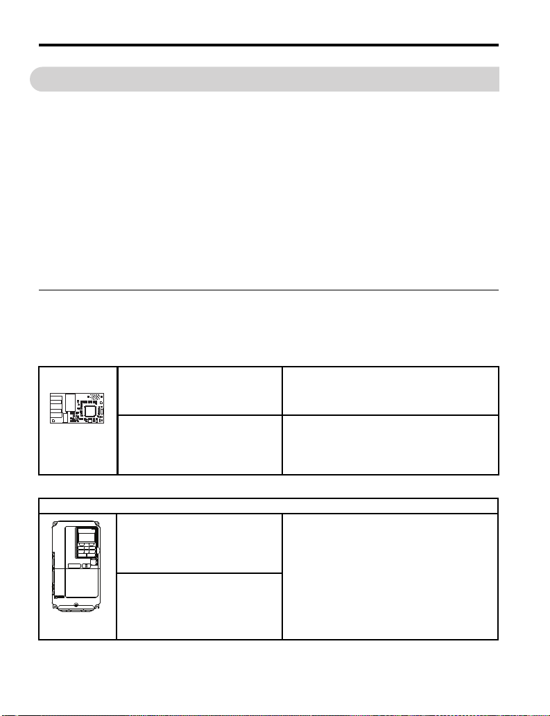
The following manuals are available for the SI-EP3 option:
SI-EP3 Option
Yaskawa AC Drive 1000-Series Option
SI-EP3 PROFINET Installation Manual
Manual No: TOEP YEACOM 07
(This manual)
Yaskawa AC Drive 1000-Series Option
SI-EP3 PROFINET Technical Manual
Manual No: SIEP YEACOM 07
Read this manual first.
The installation manual is packaged with the SI-EP3
option and contains information required to install the
option and set up related drive parameters.
The technical manual contains detailed information
about the option. In the U.S., access
http://www.yaskawa.com to obtain the technical
manual. Customers in other areas should contact a
Yaskawa representative.
Yaskawa Drive
Yaskawa AC Drive
1000-Series Quick Start Guide
A1000 - TOEPC71061641
P1000 - TOEPYAIP1U01
iQpump1000 - TOEPYAIP1W01
Yaskawa AC Drive
1000-Series Technical Manual
A1000 - SIEPC71061641
P1000 - SIEPYAIP1U01
iQpump1000 - SIEPYAIP1W01
4 YASKAWA TOEP YEACOM 07A 1000-Series Option PROFINET SI-EP3 Installation Manual
The drive manuals cover basic installation, wiring,
operation procedures, functions, troubleshooting, and
maintenance information.
The manuals also include important information
about parameter settings and drive tuning.
Access these sites to obtain Yaskawa instruction
manuals:
U.S.: http://www.yaskawa.com
Europe: http://www.yaskawa.eu.com
Japan: http://www.e-mechatronics.com
Other areas: contact a Yaskawa representative.
Page 5

◆ Terms
Note: Indicates supplemental information that is not related to safety messages.
Drive: Yaskawa AC Drive 1000-Series
Option: Yaskawa AC Drive 1000-Series SI-EP3 PROFINET option
◆ Registered Trademarks
• All trademarks are the property of their respective owners.
1 Preface and Safety
YAS KA WA TOEP YEACOM 07A 1000-Series Option PROFINET SI-EP3 Installation Manual 5
Page 6
1 Preface and Safety
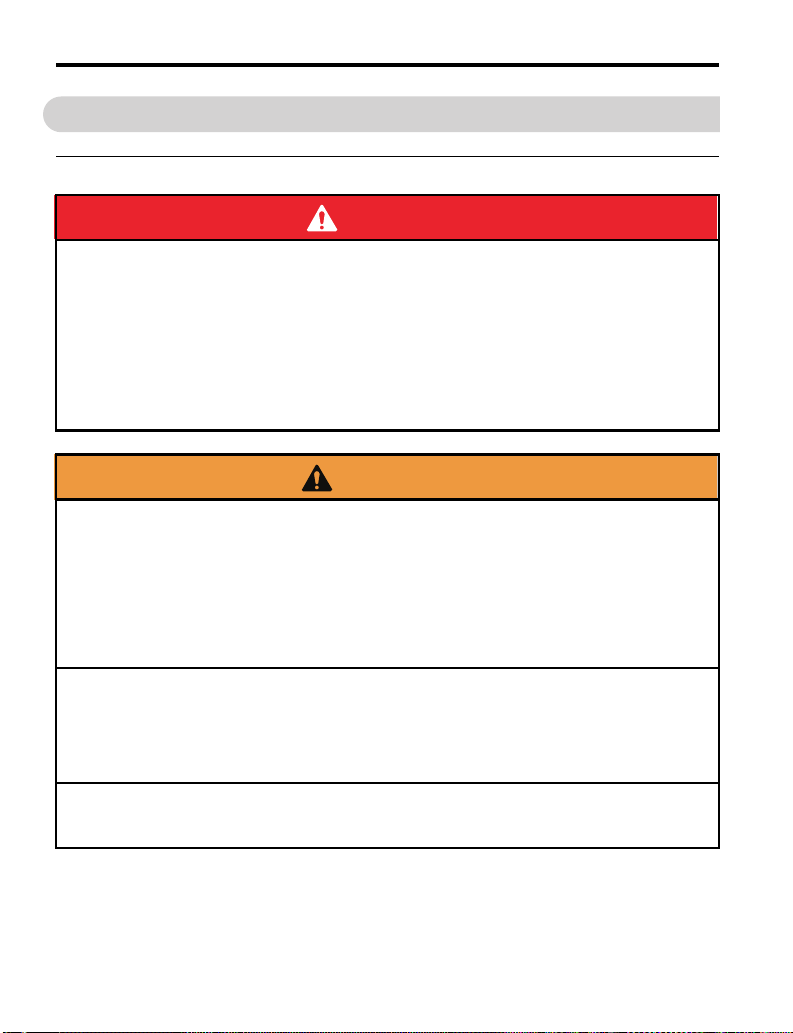
DANGER
W ARNING
CAUTION
NOTICE
◆ Supplemental Safety Information
Read and understand this manual before installing, operating, or servicing this option. The
option must be installed according to this manual and local codes.
The following conventions are used to indicate safety messages in this manual. Failure to
heed these messages could result in serious or possibly even fatal injury or damage to the
products or to related equipment and systems.
Indicates a hazardous situation, which, if not avoided, will result in death or serious
injury.
Indicates a hazardous situation, which, if not avoided, could result in death or
serious injury.
Indicates a hazardous situation, which, if not avoided, could result in minor or
moderate injury.
Indicates an equipment damage message.
6 YAS KAWA TOEP YEACOM 07A 1000-Series Option PROFINET SI-EP3 Installation Manual
Page 7
1 Preface and Safety
DANGER
NOTICE
■ General Safety
General Precautions
• The diagrams in this section may include options and drives without covers or safety shields to illustrate details.
Reinstall covers or shields before operating any devices. The option should be used according to the instructions
described in this manual.
• Any illustrations, photographs, or examples used in this manual are provided as examples only and may not apply
to all products to which this manual is applicable.
• The products and specifications described in this manual or the content and presentation of the manual may be
changed without notice to improve the product and/or the manual.
• When ordering new copies of the manual, contact a Yaskawa representative or the nearest Yaskawa sales office and
provide the manual number shown on the front cover.
Heed the safety messages in this manual.
Failure to comply will result in death or serious injury.
The operator is responsible for injuries or equipment damage caused from failure to heed
the warnings in the manual.
Do not expose the drive to halogen group disinfectants.
Failure to comply may cause damage to the electrical components in the option.
Do not pack the drive in wooden materials that have been fumigated or sterilized.
Do not sterilize the entire package after the product is packed.
Do not modify the drive or option circuitry.
Failure to comply could result in damage to the drive or option and will void warranty.
Yaskawa is not responsible for any modification of the product made by the user. This
product must not be modified.
YAS KA WA TOEP YEACOM 07A 1000-Series Option PROFINET SI-EP3 Installation Manual 7
Page 8

2 Product Overview
2 Product Overview
◆ About This Product
The SI-EP3 option connects the 1000-series drives to a PROFINET network and facilitates
the exchange of data.
This manual explains the handling, installation and specifications of this product.
The SI-EP3 option is a simple, networking solution that reduces the cost and time to wire
and install factory automation devices, while providing interchangeability of like
components from multiple vendors.
By installing the option to a drive, it is possible to do the following from a PROFINET
master device:
• Operate the drive
• Monitor the operation status of the drive
• Change parameter settings.
SI-EP3 is PROFINET Conformance Class A certified.
◆ Applicable Models
The option can be used with the drive models in Tab le 1 .
Table 1 Applicable Models
Drive Series Drive Model Number Software Version <1>
CIMR-A2A
A1000
iQpump1000
P1000
<1> See “PRG” on the drive nameplate for the software version number.
CIMR-A4A
CIMR-A5A
CIMR-A4A0930~1200 VSA903014 and greater
CIMR-PW2A
CIMR-PW5A
CIMR-PW4A0930~1200 VSA903750 and greater
CIMR-PU2A
CIMR-PU5A
CIMR-PU4A0930~1200 VSA903700 and greater
VSA90101
VSA90504
VSA90101
VSA8550 and greaterCIMR-PW4A
VSA8500 and greaterCIMR-PU4A
8 YASKAWA TOEP YEACOM 07A 1000-Series Option PROFINET SI-EP3 Installation Manual
Page 9
3 Receiving
3 Receiving
Please perform the following tasks upon receipt of the option:
• Inspect the option for damage. Contact the shipper immediately if the option appears
damaged upon receipt.
• Verify receipt of the correct model by checking the model number printed on the name
plate of the option package.
• Contact your supplier if you have received the wrong model or the option does not
function properly.
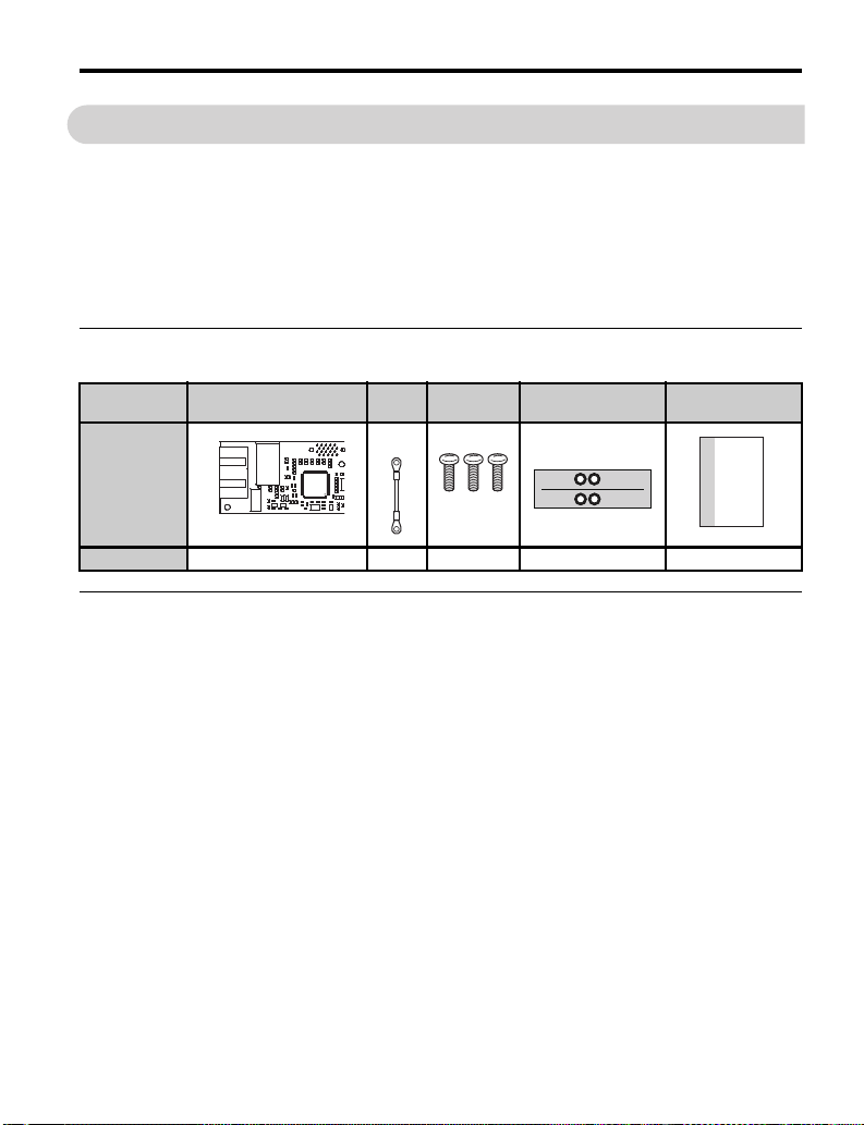
◆ Option Package Components
Description: Option
_
Quantity: 1 1 3 1 1
Ground
Screws (M3) LED Label
Wire
NS MS
Installation
Manual
MANUAL
◆ Tools Required for Installation
• A Phillips screwdriver (M3 metric/#1, #2 U.S. standard size*) is required to install the
option and remove drive front covers.
• Diagonal cutting pliers. (required for some drive models)
• A small file or medium grit sandpaper. (required for some drive models)
*Screw sizes vary by drive capacity. Select a screwdriver appropriate for the drive capacity.
Note: Tools required to prepare option networking cables for wiring are not listed in this manual.
YAS KA WA TOEP YEACOM 07A 1000-Series Option PROFINET SI-EP3 Installation Manual 9
Page 10
4 Option Components
N
A
I
H
G
E
B
D
F
C
J
L
K
M
Underside
4 Option Components
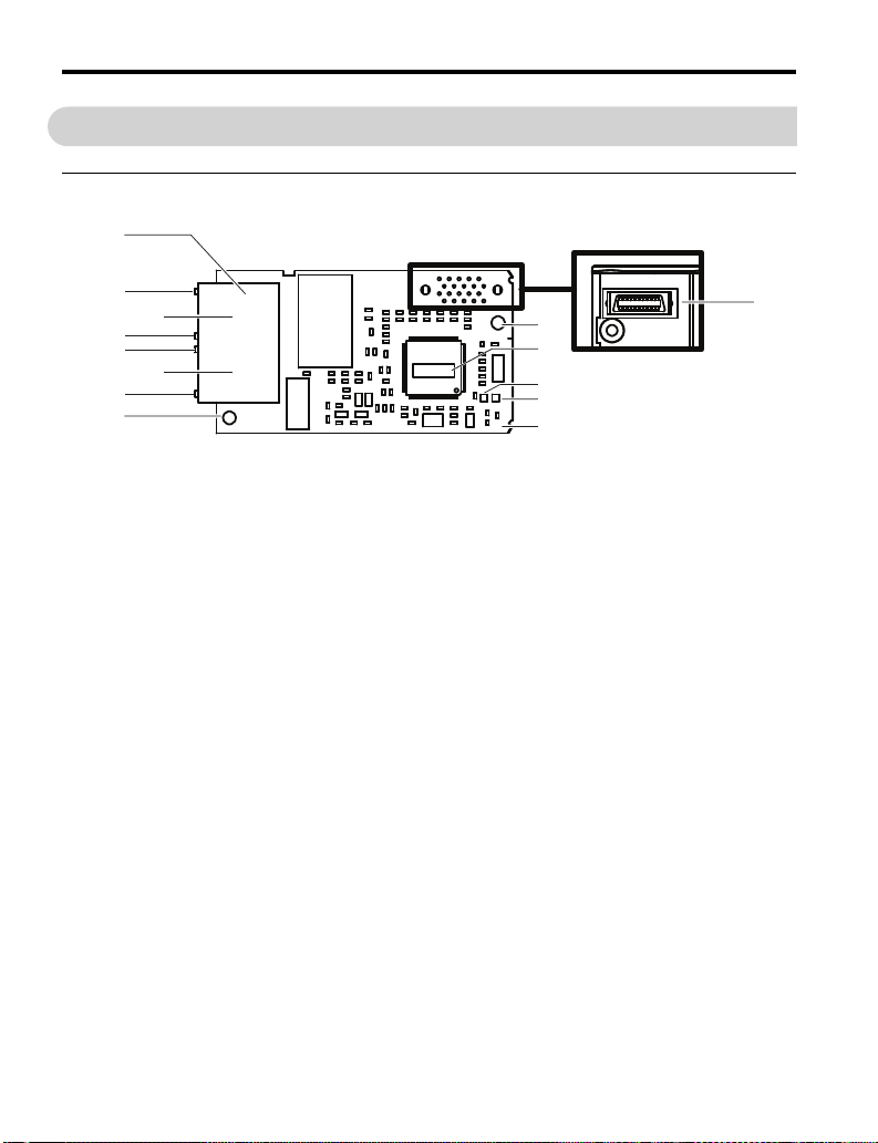
◆ SI-EP3 PROFINET Option
Figure 1
A – Ground Terminal and installation hole
B – CN1 Port 2 LED (10/100)
C – CN1 Port 2 J – Installation hole
D – CN1 Port 2 LED (LINK/ACT)
E – CN1 Port 1 LED (10/100)
F – CN1 Port 1 M – LED (MS) <2>
G – CN1 Port 1 LED (LINK/ACT) <2>
<1> The ground wire provided in the option shipping package must be connected during installation.
<2> Refer to Option LED Display on page 12 for details on the LEDs.
<2>
<2> K – SI-EP3 Firmware Label
<2> L–LED (NS)<2>
Figure 1 Option (Top View)
<1> H – PROFINET cable connection
I – Option connector CN5
VST-
N – PROFINET PCB
10 YASKAWA TOEP YEACOM 07A 1000-Series Option PROFINET SI-EP3 Installation Manual
Page 11
4 Option Components
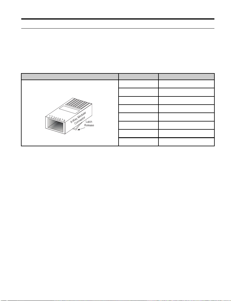
◆ Terminal CN1
The communication connector on the option is a modular RJ45 female connector
designated CN1.
CN1 is the connection point for a customer supplied male Ethernet network
communication cable.
Table 2 Male, 8-way Ethernet Modular Connector (Customer Supplied)
Male Ethernet 8-Way Modular Connector Pin Description
1 (Pair 2) Transmit data (TXD) +
2 (Pair 2) Transmit data (TXD) -
3 (Pair 3) Receive data (RXD) +
4 (Pair 1) Not used
5 (Pair 1) Not used
6 (Pair 3) Receive data (RXD) -
7 (Pair 4) Not used
8 (Pair 4) Not used <1>
<1> Not used for 10 Mbps and 100 Mbps networks.
<1>
<1>
<1>
YAS KA WA TOEP YEACOM 07A 1000-Series Option PROFINET SI-EP3 Installation Manual 11
Page 12

4 Option Components
◆ Option LED Display
The option has six LEDs:
Bi-color Status LEDs:
• Module status (MS) red/green
• Network status (NS) red/green
PROFINET LEDs:
• Network speed-10/100 yellow
• Link status and network activity-Link/Act green
The operational states of the option LEDs after the power-up diagnostic LED sequence is
completed are described in Table 3. The states with a number in parenthesis are the number
of pulses of 250 ms on, 250 ms off cycles, followed by 500 ms off, then repeating the cycle.
Wait at least 2 seconds for the power-up diagnostic process to complete before verifying
LED states.
Table 3 Option LED States
Name
MS
(visible
through
drive cover)
Indication
Color Status
– OFF Power supply OFF
Green ON Option operating
Green Flashing (1) Diagnostics Diagnostic data available.
Green Flashing (2) Configuration tool Identified by a configuration tool.
Red ON
Red Flashing (1) Configuration error (non-fatal) Configuration error.
Red Flashing (2) No IP (non-fatal) No IP address assigned.
Red Flashing (3) No station name (non-fatal) No station name assigned.
Red Flashing (4) Init failure (non-fatal) Failed to initialize module.
Green/
Red
Flashing Option self-test The option is in self-test mode.
Operating Status Remarks
Power is not being supplied to the
drive.
The option is operating normally and
initialization is complete.
Default MAC or fatal error
occurred.
Default MAC address has been
programmed or the option has
detected an unrecoverable error.
12 YASK AWA TOEP YEACOM 07A 1000-Series Option PROFINET SI-EP3 Installation Manual
Page 13

4 Option Components
Name
NS
(visible
through
drive cover)
10/100
(visible at
cable ports)
LINK/ACT
(visible at
cable ports)
Indication
Color Status
– OFF Offline or Power supply OFF –
Green ON Connected
Green Flashing Connected and stopped
Red ON BUS fault Unrecoverable BUS fault.
Red Flashing (1) Lost communication
Red Flashing (2) Lost link No link detected to network.
Yellow OFF 10 Mbps is established –
Yellow ON 100 Mbps is established –
Green OFF Link is not established –
Green ON Link is established –
Green Flashing
Operating Status Remarks
Connection established with I/O
controller and in RUN mode.
Connection established with I/O
controller and in STOP mode.
Host communication is temporarily
lost.
Link is established and there is
network activity
–
■ Power-Up Diagnostics
An LED test is performed each time the drive is powered up. The initial boot sequence may
take several seconds. After the LEDs have completed the diagnostic LED sequence, the
option is successfully initialized. The LEDs then assume operational conditions as shown in
Ta bl e 3.
Table 4 Power-Up Diagnostic LED Sequence
Sequence Module Status (MS) Network Status (NS) Time (ms)
1 Green OFF 250
2RedOFF250
3 Green OFF -
4 Green Green 250
5 Green Red 250
6 Green OFF -
YAS KA WA TOEP YEACOM 07A 1000-Series Option PROFINET SI-EP3 Installation Manual 13
Page 14
5 Installation Procedure
DANGER
W ARNING
5 Installation Procedure
◆ Section Safety
Electrical Shock Hazard
Do not connect or disconnect wiring while the power is on.
Failure to comply will result in death or serious injury.
Disconnect all power to the drive, wait at least five minutes after all indicators are off,
measure the DC bus voltage to confirm safe level, and check for unsafe voltages before
servicing. The internal capacitor remains charged after the power supply is turned off. The
charge indicator LED will extinguish when the DC bus voltage is below 50 Vdc.
Electrical Shock Hazard
Do not remove the option cover while the power is on.
Failure to comply could result in death or serious injury.
The diagrams in this section may include options and drives without covers or safety
shields to show details. Be sure to reinstall covers or shields before operating any devices.
Use the option according to the instructions described in this manual.
Do not allow unqualified personnel to use equipment.
Failure to comply could result in death or serious injury.
Maintenance, inspection, and replacement of parts must be performed only by authorized
personnel familiar with installation, adjustment, and maintenance of this product.
Do not touch circuit boards while the power to the drive is on.
Failure to comply could result in death or serious injury.
14 YASKAWA TOEP YEACOM 07A 1000-Series Option PROFINET SI-EP3 Installation Manual
Page 15

5 Installation Procedure
NOTICE
W ARNING
Do not use damaged wires, stress the wiring, or damage the wire insulation.
Failure to comply could result in death or serious injury.
Fire Hazard
Tighten all terminal screws to the specified tightening torque.
Loose electrical connections could result in death or serious injury by fire due to
overheating of electrical connections.
Damage to Equipment
Observe proper electrostatic discharge (ESD) procedures when handling the option,
drive, and circuit boards.
Failure to comply may result in ESD damage to circuitry.
Never shut the power off while the drive is running or outputting voltage.
Failure to comply may cause the application to operate incorrectly or damage the drive.
Do not operate damaged equipment.
Failure to comply may cause further damage to the equipment.
Do not connect or operate any equipment with visible damage or missing parts.
Do not use unshielded cable for control wiring.
Failure to comply may cause electrical interference resulting in poor system performance.
Use shielded twisted-pair wires and ground the shield to the ground terminal of the drive.
Properly connect all pins and connectors.
Failure to comply may prevent proper operation and possibly damage equipment.
Check wiring to ensure that all connections are correct after installing the option
and connecting any other devices.
Failure to comply may result in damage to the option.
YAS KA WA TOEP YEACOM 07A 1000-Series Option PROFINET SI-EP3 Installation Manual 15
Page 16
5 Installation Procedure
A
B
C
E
F
D
I
K
L
H
J
G
N
NS MS
M
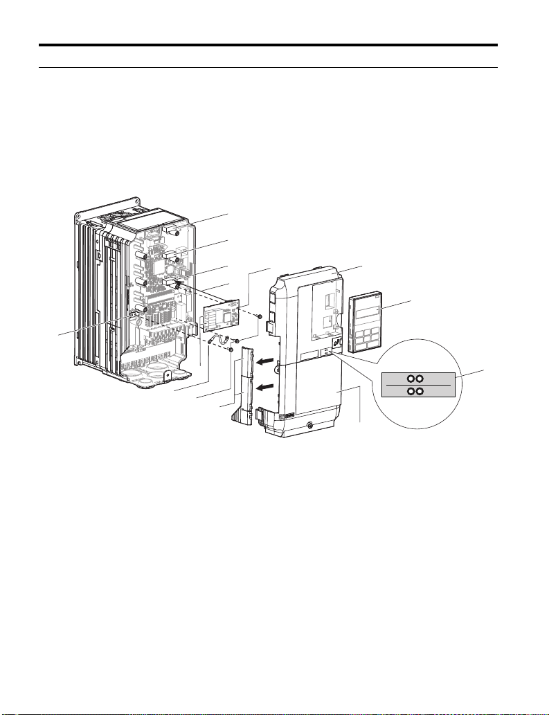
◆ Prior to Installing the Option
Prior to installing the option, wire the drive, make necessary connections to the drive
terminals, and verify that the drive functions normally without the option installed. Refer to
the product manual packaged with the drive for information on wiring and connecting the
drive.
Figure 2 shows an exploded view of the drive with the option and related components for
reference.
Figure 2
A – Connector CN5-C H – LED label
B – Connector CN5-B I – Drive terminal cover
C – Connector CN5-A J – Removable tabs for wire routing
D – Insertion point for CN5 connector K – Included screws
E – SI-EP3 option L – Ground wire
F – Drive front cover M – PROFINET cable connection CN1
G – Digital operator N – Drive grounding terminal (FE)
16 YASK AWA TOEP YEACOM 07A 1000-Series Option PROFINET SI-EP3 Installation Manual
Figure 2 Drive Components with Option
Page 17
5 Installation Procedure
◆ Installing the Option
Remove the front covers of the drive before installing the option. Refer to the drive product
manual for directions on removing the front covers. Cover removal varies depending on
drive size. This option can be inserted only into the CN5-A connector located on the drive
control board.
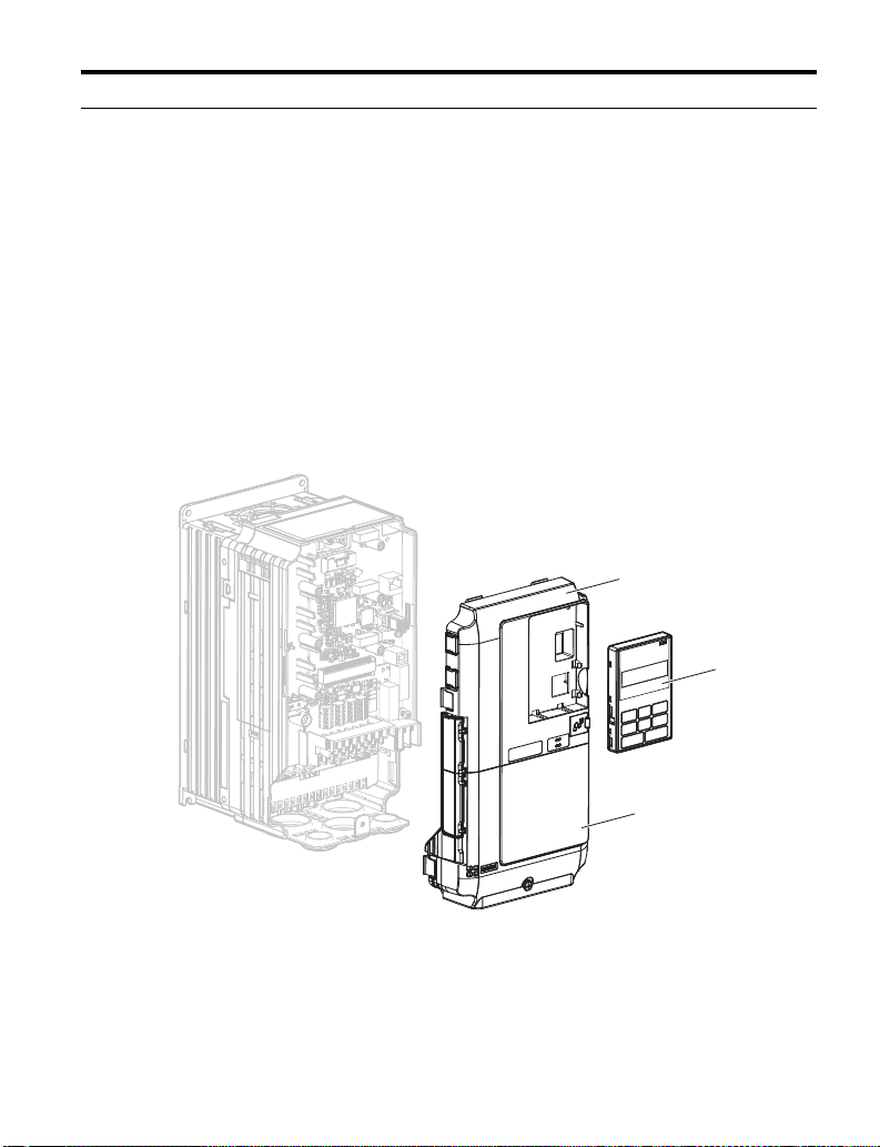
1. Shut off power to the drive, wait the appropriate amount of time for voltage to
dissipate, then remove the digital operator (G) and front covers (F, I). Front cover
removal varies by model.
DANGER! Electrical Shock Hazard. Do not connect or disconnect wiring while the power is on. Failure to
comply will result in death or serious injury. Before installing the option, disconnect all power to the drive.
The internal capacitor remains charged even after the power supply is turned off. The charge indicator LED
will extinguish when the DC bus voltage is below 50 Vdc. To prevent electric shock, wait at least five minutes
after all indicators are off and measure the DC bus voltage level to confirm safe level.
NOTICE: Damage to Equipment. Observe proper electrostatic discharge procedures (ESD) when handling
the option, drive, and circuit boards. Failure to comply may result in ESD damage to circuitry.
Figure 3
F
G
I
Figure 3 Remove the Front Covers and Digital Operator
YAS KA WA TOEP YEACOM 07A 1000-Series Option PROFINET SI-EP3 Installation Manual 17
Page 18

5 Installation Procedure
NS
MS
C
D
K
E
2. With the front covers and digital operator removed, apply the LED label (H) in the
Figure 4
appropriate position on the drive top front cover (F).
F
NS MS
H
Figure 4 Apply the LED Label
3. Insert the option (E) into the CN5-A connector (C) located on the drive and fasten it
Figure 5
using one of the included screws (K).
Figure 5 Insert the Option
18 YASK AWA TOEP YEACOM 07A 1000-Series Option PROFINET SI-EP3 Installation Manual
Page 19

5 Installation Procedure
NS
MS
K
L
E
N
4. Connect the ground wire (L) to the ground terminal (N) using one of the remaining
provided screws (K). Connect the other end of the ground wire (L) to the remaining
ground terminal and installation hole on the option (E) using the last remaining
Figure 6
provided screw (K) and tighten both screws to 0.5 ~ 0.6 nm or (4.4 ~ 5.3 in lbs).
Figure 6 Connect the Ground Wire
Note: There are two screw holes on the drive for use as ground terminals. When connecting three
options, two ground wires will need to share the same drive ground terminal.
YAS KA WA TOEP YEACOM 07A 1000-Series Option PROFINET SI-EP3 Installation Manual 19
Page 20

5 Installation Procedure
B
A
■ Wiring the Option
5. Route the option wiring.
Depending on the drive model, some drives may require routing the wiring through
the side of the front cover to the outside to provide adequate space for the wiring. In
these cases, using diagonal cutting pliers, cut out the perforated openings on the
left side of the drive front cover. Sharp edges along the cut out should be smoothed
down with a file or sand paper to prevent any damage to the wires.
5.a Route the PROFINET CAT 5e cable inside the enclosure for drives that do not
require routing through the front cover. Refer to Table 5 and Figure 7 to determine the
proper wire routing by drive model.
Table 5 Model-Specific Cable Routing
Model CIMR-
2A0004 to 0040; 4A0002 to 0023; 5A0003 to 0011 Figure 7 (A) -
2A0056 and above; 4A0031 and above; 5A0023 and above. - Figure 7 (B)
<1> Refer to Figure 7 for examples of the different wire routing techniques.
Figure 7
Wire Routing <1>
Through Front
Cover
Inside Drive
A – Route wires through the openings
<1> The drive will not meet NEMA Type 1 requirements if wiring is exposed outside the enclosure.
20 YASK AWA TOEP YEACOM 07A 1000-Series Option PROFINET SI-EP3 Installation Manual
provided on the left side of the
front cover.
<1>
Figure 7 Wire Routing Examples
B – Use the open space provided
inside the drive to route option
wiring.
Page 21

5 Installation Procedure
Traditional Star Network Daisy Chain Network
Cable Topology A
Cable Topology B
Yaskawa
Drive
Yaskawa
Drive
Yaskawa
Drive
Yaskawa
Drive
Yaskawa
Drive
Yaskawa
Drive
STOP
(Hz)
(Hz)
(A)
(V)
V1000
V1000 V1000 V1000 V1000 V1000
6. Connect the PROFINET CAT 5e communication cable to the option connector
(CN1) port 1.
To connect the option to a network, firmly connect RJ45 8-pin Shielded Twisted Pair
CAT 5e cable(s) into the modular connector ports (see Figure 7). Refer to Network
Topology and Connections on page 21.
NOTICE: Do not connect or disconnect the communication cable while the drive is powered up or while the drive is in
operation. Failure to comply may cause a static discharge, which will cause the option card to stop working properly.
Cycle power on the drive and option card to reestablish functionality.
■ Network Topology and Connections
The dual RJ45 network ports on the option board act as a switch to allow for flexibility in
cabling topology. For example, a traditional star network topology may be employed by
using a single port on the option board. Alternatively, a daisy-chained approach may be
employed by using both RJ45 ports. This second approach reduces the requirements of
central switch ports.
Figure 8
Figure 8 Topology Options
Communication Cable Specifications
Use cables recommended for PROFINET. Using a cable not specifically recommended may
cause the option or drive to malfunction.
The use of CAT5e or equivalent Shielded Twisted Pair (STP) cable is recommended.
YAS KA WA TOEP YEACOM 07A 1000-Series Option PROFINET SI-EP3 Installation Manual 21
Page 22

5 Installation Procedure
Yaskawa
Drive
M
U/T1
V/T2
W/T3
R/L1
S/L2
T/L3
SI-EP3
PROFINET
Option
FE
<1>
PROFINET Master
PROFINET Cable
MotorPower
PROFINET Cable
7. Use the second communication cable port to daisy chain a series of drives where
applicable. Refer to Figure 8.
■
Connection Diagram
<1> The ground wire provided in the option shipping package must be connected during installation.
Figure 9 Wiring Diagram
8. Replace and secure the front covers of the drive (F, I) and replace the digital
operator (G).
22 YASK AWA TOEP YEACOM 07A 1000-Series Option PROFINET SI-EP3 Installation Manual
Page 23

5 Installation Procedure
MSM
S
I
F
G
Figure 9
Figure 10 Replace the Front Covers and Digital Operator
NOTICE: Damage to Equipment. Observe proper electrostatic discharge procedures (ESD) when handling
the option, drive, and circuit boards. Failure to comply may result in ESD damage to circuitry.
9. Set drive parameters in Table 6 for proper option performance.
◆ GSDML Files
For easy network implementation of drives equipped with the SI-EP3 option, a GSDML file
can be obtained from:
U.S.: http://www.yaskawa.com
Other areas: Contact a Yaskawa representative.
YAS KA WA TOEP YEACOM 07A 1000-Series Option PROFINET SI-EP3 Installation Manual 23
Page 24

6 Option Related Drive Parameters
6 Option Related Drive Parameters
The following parameters are used to set up the drive for operation with the option.
Parameter setting instructions can be found in the drive product manual.
Confirm proper setting of the all parameters in Table 6 before starting network
communications.
Table 6 Parameter Settings
No. Name Description Default
Selects the frequency reference input source.
b1-01
<1>
b1-02
<1>
F6-01
F6-02
F6-03
F6-07
F6-08
Frequency Reference
Selection
Run Command
Selection
Operation Selection
after Communications
Error
External Fault
Detection Conditions
(EF0)
Stopping Method for
External Fault from
Communication Option
Board
NetRef/ComRef
Selection Function
Reset Communication
Related Parameters
0: Operator - Digital preset speed d1-01 to d1-17
1: Terminals - Analog input terminal A1 or A2
2: MEMOBUS/Modbus communications
3: Option PCB
4: Pulse Input (Terminal RP)
Selects the run command input source.
0: Digital Operator - RUN and STOP keys
1: Digital input terminals S1 to S7
2: MEMOBUS/Modbus communications
3: Option PCB
Determines drive response when a bUS error is detected
during communications with the option.
0: Ramp to Stop
1: Coast to Stop
2: Fast-Stop
3: Alarm Only
4: Alarm (d1-04) <2> <3>
5: Alarm Ramp to Stop <2> <3>
Sets the condition for external fault detection (EF0).
0: Always detected
1: Detected only during operation
Determines drive response for external fault input (EF0)
detection during communication.
0: Ramp to Stop
1: Coast to Stop
2: Fast-Stop
3: Alarm Only
0: Multi-step speed reference disabled
1: Multi-step speed reference allowed
Determines if communication-related parameters F6-
and F7- are set back to original default values when the
drive is initialized using parameter A1-03.
0: Do not reset F6- and F7- parameters
1: Reset F6- and F7- parameters
Note: Setting this parameter does not affect
communication-related parameters.
<2>
<2>
(Set to 3 for
PROFINET)
(Set to 3 for
PROFINET)
1
1
1
0
1
1
0
24 YASKAWA TOEP YEACOM 07A 1000-Series Option PROFINET SI-EP3 Installation Manual
Page 25

6 Option Related Drive Parameters
No. Name Description Default
F6-14 <3> bUS Error Auto Reset
F7-01
to
F7-04
F7-05
F7-08
F7-09
F7-12
F7-13
F7-14
F7-15
F7-16 <3>
F7-23
F7-27
IP Address
to
Subnet Mask
to
Gateway Address
Address Mode at
Startup
Duplex Mode Selection
Communication Speed
Selection
Communication Loss
Timeout
Dynamic Output
Assembly
Parameters
(SI-EP3 Firmware
Version VST800250)
to
Dynamic Output
Assembly
Parameters
(SI-EP3 Firmware
Version VST800251)
0: Disabled
1: Enabled
Sets static IP address of the SI-EP3 option when parameter
F7-13=0.
Note: Parameter F7-01 sets the most significant octet.
Sets static Subnet Mask of network connection.
Note: Parameter F7-05 sets the most significant octet
Sets static Gateway address of network connection.
Note: Parameter F7-09 sets the most significant octet.
Selects how the option address is set.
0: Static
2: DCP
Selects duplex mode setting.
0: Half duplex forced
1: Auto-negotiate duplex mode and communication speed
2: Full duplex forced
3: Half (port 1)/Auto (port 2) <3>
4: Half (port 1)/Full (port 2) <3>
5: Auto (port 1)/Half (port 2) <3>
6: Auto (port 1)/Full (port 2) <3>
7: Full (port 1)/Half (port 2) <3>
8: Full (port 1)/Auto (port 2) <3>
Sets the communication speed.
10: 10 Mbps
100: 100 Mbps
101: 10 (port 1)/100 Mbps (port 2)
102: 100 (port 1)/10 Mbps (port 2) <3>
Sets the timeout value for communication loss detection in
tenths of a second.
A value of 0 disables the connection timeout.
Example: An entered value of 100 represents 10.0 seconds.
Configurable outputs 1 to 5.
If a value other than 0 is assigned to parameters F7-23 to
F7-27 and F7-33 to F7-37 by the drive, that value will take
precedent over a value set by the configuration software.
If the value in the drive is 0 (default), the value from the
configuration software will be used.
Configurable outputs 1 to 5.
If a value other than 0 is assigned in the configuration
software, those values will be used, otherwise, the values of
the drive parameters set in parameters F7-23 to F7-27 and
F7-33 to F7-37 will be used.
<3>
192 168 1 20
255 255 255 0
192 168 1 1
Default: 10
Range: 10;
100 to 102
Default: 0.0 s
Min.: 0.0 s
Max.: 30.0 s
0
2
1
0
YAS KA WA TOEP YEACOM 07A 1000-Series Option PROFINET SI-EP3 Installation Manual 25
Page 26

6 Option Related Drive Parameters
No. Name Description Default
Dynamic Input
Assembly
Parameters
F7-33
F7-37
H5-11
<1> To start and stop the drive with the option master device using serial communications, set b1-02 to 3. To control
<2> If F6-01 is set to 3, 4, or 5, then the drive will continue to operate when a bUS fault is detected. Take proper safety
<3> The availability of this feature/function is depends on drive model, software version and Profinet firmware
(SI-EP3 Firmware
Version VST800250)
to
Dynamic Input
Assembly
Parameters
(SI-EP3 Firmware
Version VST800251)
Communications
ENTER Function
Selection
the drive frequency reference via the master device, set b1-01 to 3.
measures, such as installing an emergency stop switch.
version. Refer to Table 15 for specifics relating to your drive.
Configurable inputs 1 to 5.
If a value other than 0 is assigned to parameters F7-23 to
F7-27 and F7-33 to F7-37 by the drive, that value will take
precedent over a value set by the configuration software.
If the value in the drive is 0 (default), the value from the
configuration software will be used.
Configurable outputs 1 to 5.
If a value other than 0 is assigned in the configuration
software, those values will be used, otherwise, the values of
the drive parameters set in parameters F7-23 to F7-27 and
F7-33 to F7-37 will be used.
Select the function for the ENTER command that saves
parameter data to the drive.
0: Parameter changes are activated when ENTER command
is written
1: Parameter changes are activated immediately without use
of ENTER command
0
1
26 YASK AWA TOEP YEACOM 07A 1000-Series Option PROFINET SI-EP3 Installation Manual
Page 27

6 Option Related Drive Parameters
Table 7 Option Monitors
No. Name Description Value Range
U6-80 to U6-83 Online IP Address
U6-84 to U6-87 Online Subnet Subnet, U6-94 is the most significant octet. 0 to 255
U6-88 to U6-91 Online Gateway Gateway, U6-88 is the most significant octet. 0 to 255
U6-92 Online Speed Port 1 Link Speed 10, 100
U6-93 Online Duplex Port 1 Duplex Setting 0: Half, 1: Full
U6-94 Online Duplex Port 2 Link Speed 0: Half, 1: Full
U6-95 Online Duplex Port 2 Duplex Setting 0: Half, 1: Full
U6-98 First Fault First Option Board Fault -
U6-99 Current Fault Current Option Board Fault -
SI-EP3 IP Address, U6-80 is the most significant
octet.
0 to 255
YAS KA WA TOEP YEACOM 07A 1000-Series Option PROFINET SI-EP3 Installation Manual 27
Page 28

7 Web Interface
7 Web Interface
The web server interface to the drive option through port 80 allows management of
diagnostic information through a standard web browser. The web page is a Java applet that
creates a tabbed web page. The available tabs include:
Note: PCs must have Java SE 6 Update 14 or later installed to view the web pages. PCs without Java
will display web pages with limited features.
Web page interface screens are shown for all SI-EP3 firmware versions, VST800251 and for
VST800250 and prior.
Refer to SI-EP3 Firmware Update on page 42 to update SI-EP3 option firmware, if the web
interface pages associated with VST800251 are needed
Table 8 Web Server Interface Web Page Tabs
Tab N am e
HTML Home Page (Main) --9 29
Main 9 30 9 31
Drive Status 9 32
Network 9 33 9 33
Email Alerts
Doc Links 9 36
Parameter Access
Configuration
Custom Tab 9 40 9 41
<1> The Parameter Access Tab and Configuration Tab are only accessible after entering a valid password.
<1>
<1>
SI-EP3 Option Firmware Version Web Page Tab Availability
VST800250 and Prior Page No. VST800251 and Later Page No.
9
9
34
9
-
9
9
37
38
9
9
32
34
-
37
38
◆ Web Server Interface
Access the web server interface by typing the IP address of the SI-EP3 option in a web
browser address.
Example: "http://192.168.1.20"
The SI-EP3 IP Address is available using drive digital operator to access Option Monitors
U6-80 to U6-83. Refer to Option Monitors on page 27.
28 YASKAWA TOEP YEACOM 07A 1000-Series Option PROFINET SI-EP3 Installation Manual
Page 29

7 Web Interface
■ HTML Home Page (SI-EP3 firmware version VST800251 and later)
The main HTML home page provides basic drive and option data and a link to an enhanced
web page.
Figure 10
Figure 11 HTML Home Page
YAS KA WA TOEP YEACOM 07A 1000-Series Option PROFINET SI-EP3 Installation Manual 29
Page 30

7 Web Interface
1016
CIMR-AU4A0009
■ Main Tab (SI-EP3 firmware version VST800250 and prior)
The Main tab shows basic option information such as IP address, MAC address, and
firmware version.
Figure11
Figure 12 Main Tab View
30 YASK AWA TOEP YEACOM 07A 1000-Series Option PROFINET SI-EP3 Installation Manual
Page 31

7 Web Interface
■ Main Tab (SI-EP3 firmware version VST800251 and later)
The Main tab shows basic option information such as IP address, MAC address, and
firmware version.
Figure 12
Figure 13 Main Tab View
YAS KA WA TOEP YEACOM 07A 1000-Series Option PROFINET SI-EP3 Installation Manual 31
Page 32

7 Web Interface
■ Drive Status Tab
The Drive Status tab shows basic I/O information and drive state information.
Figure 13
Figure 14 Drive Status Tab View
32 YASK AWA TOEP YEACOM 07A 1000-Series Option PROFINET SI-EP3 Installation Manual
Page 33

7 Web Interface
■ Network Tab
The Network tab shows the status of the option network traffic and the status of open I/O
connections.
Figure 14
Figure 15 Network Tab View
Table 9 Network Monitor Descriptions
Network Monitor Explanation
Msg Tx OK Cumulative number of messages transmit successfully from SI-EP3.
Msg Rx OK Cumulative number of messages received successfully to SI-EP3.
Current Connections Current number of open connections.
Control Connection Delta
Time
Msg Tx Dropped
Msg Rx Dropped
Collisions
Msg Tx Errors
Msg Rx Errors
Tx Retry
Note: Cumulative counters are reset when the power supply is cycled.
The time between the last two writes to the Control register, MEMOBUS/Modbus
address 0001H.
Cumulative number of messages dropped due to output network buffer being full and
unable to hold the new message.
Cumulative number of messages dropped due to input network buffer being full and
unable to hold the new message.
Cumulative number of collisions (half duplex only) reported by the MAC/PHY
(Media Access Control/Physical Connection).
Cumulative number of transmit underruns and transmit stops reported by the
MAC/PHY.
Cumulative number of receive overruns, receive stops, and receive error frames
reported by the MAC/PHY.
Cumulative number of transmits in which the 1st attempt was delayed due to busy
medium reported by the MAC/PHY.
YAS KA WA TOEP YEACOM 07A 1000-Series Option PROFINET SI-EP3 Installation Manual 33
Page 34

7 Web Interface
■ Email Alerts Tab
The Email Alerts tab allows the user to configure four Email Fault/Alarm conditions. When
the condition is true, one email will be sent to the provided email address. Another email
will not be sent until the condition becomes false and then true again. A 30-second timer
prevents emails from being sent when conditions reoccur immediately after being removed.
The timer helps limit the amount of emails sent regarding the same intermittent condition
and helps to reduce network traffic by reducing emails about reoccurring errors.
Figure 15
Figure 16 Email Alerts Tab View
34 YASK AWA TOEP YEACOM 07A 1000-Series Option PROFINET SI-EP3 Installation Manual
Page 35

7 Web Interface
Procedure: Conditional Email Set-up
1. Define the condition that will trigger the email by selecting a monitor parameter, a
comparator, and a value. Set up comparator values for the range of values to check
in the chosen condition. If choosing only one condition and no OR or AND are
needed, set the “OR/AND” drop-down selection to “NotUsed”.
2. Enter the email address where the alert will be sent.
3. Enter the message that will appear in the email contents.
4. Enter the email subject.
5. Click the “Email Active” check box to enable the alert.
Clicking “Save to device” will save the entered information into the option memory.
Clicking “Cancel and reload” will cancel any pending edits and display the most recently
saved settings from the option board.
YAS KA WA TOEP YEACOM 07A 1000-Series Option PROFINET SI-EP3 Installation Manual 35
Page 36

7 Web Interface
SI-EP3
■ Doc Links Tab (SI-EP3 firmware version VST800250 and prior)
The Doc links tab contains links to the option documentation on the Yaskawa website.
Figure 16
Figure 17 Doc Links View
36 YASK AWA TOEP YEACOM 07A 1000-Series Option PROFINET SI-EP3 Installation Manual
Page 37

7 Web Interface
■ Parameter Access Tab
The Parameter Access tab allows the user to read and write parameters from the drive. Write
access is restricted until a valid password is entered.
Figure 17
Figure 18 Parameter Access Tab View
The MEMOBUS/Modbus address for the drive parameter being accessed must be entered in
hexadecimal. The number must begin with “0x” to signify hexadecimal.
Clicking “Read” will load and display the current value of the given MEMOBUS/Modbus
Address. Clicking “Set” will save the given value to the given MEMOBUS/Modbus address.
After a “Read” or “Set” command is given, Status will display “Waiting” while the action is
being carried out, then “Complete” is displayed when finished.
YAS KA WA TOEP YEACOM 07A 1000-Series Option PROFINET SI-EP3 Installation Manual 37
Page 38

7 Web Interface
sample@sample.
■ Configuration Tab
The Configuration tab sets web page behavior parameters. Access is restricted unless a valid
password is entered.
Figure 18
Figure 19 Configuration Tab View
Security Login
Enter a valid password and click “Log in”. The button text will change to “Log out” and the
status will change to “Logged in”.
Note: The default security password is “yaskawa”.
This password can be changed in the “Change Password” section of the tab. Entering a valid
password allows access to the settings in the Configuration tab, Email Alerts tab, and the
Parameter Access tab.
38 YASK AWA TOEP YEACOM 07A 1000-Series Option PROFINET SI-EP3 Installation Manual
Page 39

7 Web Interface
Change Password
To change the password, enter the new password in the “New Password:” and “Confirm
Password:” text boxes then click “Change password”. The Status display will change to
“Idle” then “Changing Password” then “Password Changed”. If the passwords in the two
text boxes do not match, the Status will display “Passwords don’t match”.
Option Card
The values displayed in the various tabs are refreshed at the rate defined in the “Applet
Refresh Rate (ms)” text box. Enter values in the range of 1000 ms to 65.535 seconds.
Parameter Security can be enabled or disabled by clicking one of the radio buttons. When
“Disabled” is selected, no password is necessary and all functions in the web pages will be
available. When “Enabled” is selected, a valid password must be entered to edit email
settings and to write parameters.
Email Settings
The “Email Server IP” text box must contain the IP address of the email server. The subnet
address is configured in drive parameters F7-05 through F7-08. The configured email alerts
will use the server at this address when sending emails.
Enter the email server port in the “Email Port” text box.
The value in the “From’ Email Address” text box identifies the origin of the email alerts to
the recipient.
Click “Submit Email Parameters” to save the email settings to the option.
Click “Save Configuration Parameters to Flash” to save the entered values from this tab into
non-volatile memory. These values will then be remembered after cycling power.
General Settings
Click “Save Options Card Parameters” to save the Applet Refresh Rate and the Parameter
Security settings to the option.
YAS KA WA TOEP YEACOM 07A 1000-Series Option PROFINET SI-EP3 Installation Manual 39
Page 40

7 Web Interface
■ Custom Tab (SI-EP3 firmware version VST800250 and prior)
The Custom tab displays a selection of quick setting parameters.
Figure 19
Figure 20 Custom Tab View
40 YASK AWA TOEP YEACOM 07A 1000-Series Option PROFINET SI-EP3 Installation Manual
Page 41

7 Web Interface
■ Custom Tab (SI-EP3 firmware version VST800251 and later)
The Custom tab displays a selection of quick setting parameters.
Figure 20
Figure 21 Custom Tab View
YAS KA WA TOEP YEACOM 07A 1000-Series Option PROFINET SI-EP3 Installation Manual 41
Page 42

7 Web Interface
◆ SI-EP3 Firmware Update
The Profinet SI-EP3 firmware can be updated to the most recent version.
1. Navigate to this URL:
https://www.yaskawa.com/pycprd/partner/fmw-network-communications
2. Enter your Partner Login credentials.
3. Download Communication Option Flash Write Procedure manual no.TOEPYAICOM14 for
instructions on how to update the SI-EP3 firmware.
4. Download the *.YFlash file for your specific communication option to your PC.
42 YASK AWA TOEP YEACOM 07A 1000-Series Option PROFINET SI-EP3 Installation Manual
Page 43

8 Troubleshooting
8 Troubleshooting
◆ Drive-Side Error Codes
Drive-side error codes appear on the drive digital operator. Causes of the errors and
corrective actions are listed in Table 10. For additional error codes that may appear on the
drive digital operator, refer to the drive Technical Manual.
■ Faults
Both bUS (SI-EP3 option communication error) and EF0 (External fault input from the
SI-EP3 option) can appear as an alarm or as a fault. When a fault occurs, the digital operator
ALM LED remains lit. When an alarm occurs, the ALM LED flashes.
If communication stops while the drive is running, use the following questions as a guide to
help remedy the fault:
• Is the option properly installed?
• Is the communication line properly connected to the option? Is it loose?
• Is the controller program working? Has the controller/PLC CPU stopped?
• Did a momentary power loss interrupt communications?
Table 10 Fault Display and Possible Solutions
LED Operator Display Fault Name
Option Communication Error.
bUS
Cause Possible Solution
Master controller (PLC) has stopped
communicating
Communication cable is not connected
properly
A data error occurred due to noise
Option is damaged
After establishing initial communication, the connection was lost
Only detected when the run command or frequency reference is assigned to
the option
(b1-01 = 3 or b1-02 = 3)
Check that power is supplied to the PLC
Check that PLC is not in program mode
Check for faulty wiring
Correct any wiring problems
Check the various options available to minimize the effects of noise
Counteract noise in the control circuit, main circuit, and ground wiring
If a magnetic contactor is identified as a source of noise, install a surge
absorber to the contactor coil
Make sure the cable used meets the PROFINET requirements
Make sure the option ground wire is connected between option FE terminal
and the drive ground terminal connected to earth ground
If there are no problems with the wiring and the error continues to occur,
replace the option.
YAS KA WA TOEP YEACOM 07A 1000-Series Option PROFINET SI-EP3 Installation Manual 43
Page 44

8 Troubleshooting
LED Operator Display Fault Name
EF0
Cause Corrective Action
An external fault is being sent from the upper
controller (PLC)
Problem with the PLC program
LED Operator Display Fault Name
oFA00
Cause Possible Solution
Non-compatible option connected to the drive Connect an option that is compatible with the drive.
LED Operator Display Fault Name
oFA01
Cause Possible Solution
Problem with the connectors between the drive
and option
LED Operator Display Fault Name
oFA03
Cause Possible Solution
Option hardware fault Replace the option.
External fault input from option.
The alarm function for an external device has been triggered.
Remove the cause of the external fault
Reset the external fault input from the PLC device
Check the program used by the PLC and make the appropriate
corrections.
Option fault.
Option is not properly connected.
Option fault.
Option is not properly connected.
Turn the power off and check the connectors between the drive
and option.
Option fault.
Option self-diagnostics error.
LED Operator Display Fault Name
oFA04
Cause Possible Solution
Option hardware fault Replace the option.
44 YASK AWA TOEP YEACOM 07A 1000-Series Option PROFINET SI-EP3 Installation Manual
Option fault.
Option flash write mode.
Page 45

8 Troubleshooting
LED Operator Display Fault Name
to
Option hardware fault Replace the option.
LED Operator Display Fault Name
Non-compatible option connected to the drive. Connect the correct option to CN5-A.
LED Operator Display Fault Name
Options AI-A3 or DI-A3 were connected to the
CN5-B port while an option was already
connected to CN5-A.
LED Operator Display Fault Name
Non-compatible option connected to the drive. Connect the correct option to CN5-A.
oFA30 to oFA43
Cause Possible Solution
oFb00
Cause Possible Solution
oFb02
Cause Possible Solution
oFc00
Cause Possible Solution
Option Fault (Port A).
Communication ID error.
Option fault (CN5-B).
Non-compatible option is connected.
Option fault (CN5-B).
Two of the same options are connected at the same time.
Only one type of AI-A3 or DI-A3 option can be connected to the
drive.
The SI-EP3 option can only be connected to CN5-A.
Option fault (CN5-C).
Non-compatible option is connected.
LED Operator Display Fault Name
oFc02
Cause Possible Solution
Options AI-A3 or DI-A3 are connected to the
CN5-B port with an option connected to CN5-A.
YAS KA WA TOEP YEACOM 07A 1000-Series Option PROFINET SI-EP3 Installation Manual 45
Option fault.
Option flash write mode.
Only one type of AI-A3 or DI-A3 option can be connected to the
drive
The SI-EP3 option can only be connected to CN5-A
Page 46

8 Troubleshooting
■ Minor Faults and Alarms
LED Operator Display Minor Fault Name
CALL
Cause Possible Solution
Communication wiring is faulty, there
is a short circuit, or improper
connection
Programming error on the master side
Communication circuitry is damaged.
■ bUS Error Auto-Reset
bUS Error Auto-Reset Function Description
bUS Error Auto-Reset when configured, allows the drive to automatically recover from a
bUS error as a result of a communication loss with the host.
A bUS Error will automatically reset under the following conditions.
• Network communication between the host and the drive is restored. (bUS error removed)
• bUS Error Auto-Reset is enabled as described in this section.
Enabling bUS Error Auto-Reset
Parameter F6-14
<1>
bUS Error Auto Reset enables the bUS Error Auto-Reset function.
F6-14 becomes available when the option is installed on the drive.
1. Set parameter F6-14 = 1:Enabled
2. Set parameter F6-01 = 0:Ramp to Stop, 1:Coast to Stop, 2:Fast-Stop
3. Set parameter F7-16 = 0.1 to 10.0 seconds (optional)
Enabling bUS Error Auto-Restart (After a Time Delay)
Parameter F7-16 Communication Loss Timeout will delay the occurrence of a bUS error
condition by the amount of time set in this parameter. F7-16 is set in tenths of seconds. The
status LEDs on the option will indicate the bUS error condition immediately upon detection
and during the F7-16 delay time. Refer to Figure 21.
• Set parameter F7-16 = 0.1 to 10.0 seconds (0.0 setting disables F7-16) to enable timeout
delay.
Serial communication transmission error.
Communication is not established.
Check for wiring errors:
Correct the wiring
Remove ground shorts and reconnect loose wires
Check communications at start-up and correct
programming errors.
Perform a self-diagnostics check
Replace the drive if the fault continues to occur
Minor Fault
(H2- = 10)
YES
<1>
Available in SI-EP3/V firmware version VST800251 and later. Refer to Tab le 1 5 for specifics relating to your drive
and drive software version.
46 YASK AWA TOEP YEACOM 07A 1000-Series Option PROFINET SI-EP3 Installation Manual
Page 47

8 Troubleshooting
E86
&RQGLWLRQ
E86(UURU
RQGULYH
2XWSXW
)UHTXHQF\
E86(UURU'HOD\
)!&RPP/RVV7RXW
1HWZRUN
FRQQHFWLRQ
LQWHUUXSWHG
1HWZRUN
FRQQHFWLRQ
UHWXUQV
)
VHF
)
VHF
)
VHF
Figure 21
Figure 22 bUS Error Delay Timing Example
Related Parameters
Table 11 Parameters related to bUS Error Auto-Reset Functionality
No.
(Addr. Hex)
F6-01
(03A2)
F6-14 <5>
(03BB)
F7-16 <5>
(03F4)
<2> If F6-01 is set to 3, then the drive will continue to operate when a bUS error is detected. Use caution and proper
safety measures, when installing an emergency stop switch.
<5> The availability of this feature/function depends on drive model, software version and Profinet firmware version.
Refer to Table 15 for specifics relating to your drive.
YAS KA WA TOEP YEACOM 07A 1000-Series Option PROFINET SI-EP3 Installation Manual 47
Operation Selection after
Communications Error
bUS Error Auto Reset
Communication Loss Timeout
Name Description Default
Determines drive response when a bUS error is
detected during communications with the option.
0: Ramp to Stop
1: Coast to Stop
2: Fast-Stop
3: Alarm Only
4: Alarm (d1-04) <5>
5: Alarm Ramp to Stop
0: Disabled
1: Enabled
<2>
<5>
Sets the timeout value for communication loss
detection in tenths of a second.
A value of 0 disables the connection timeout.
Example: An entered value of 100 represents 10.0
seconds.
Note: A change to this parameter setting is not
effective until main power to the drive is cycled.
1
0
0.0
Page 48

8 Troubleshooting
■ Option Fault Monitors U6-98 and U6-99
The option can declare error/warning conditions via drive monitor parameters on the drive
digital operator as shown in Ta bl e 12 .
Table 12 Option Fault Monitor Descriptions
Fault Condition Fault Declared
No Fault n/a 0 No faults.
Force Fault EF0 3
Network Link
Down
Network Failure BUS ERROR 1301 Connection with PLC Timeout.
Default MAC
Address
No IP Address None 1304 No IP Address has been programmed into the option.
No Station Name None 1305 No Station Name has been programmed into the option.
Config Error None 1306 Configuration error on power-up.
Init. Failure None 1307 Initialize error on power-up.
Permanent
Communication
Loss
BUS ERROR 1300 No network link to option board.
None 1303
BUS ERROR 1308
Two drive monitor parameters, U6-98 and U6-99, assist in network troubleshooting:
• U6-98 displays the first declared fault since the last power cycle. U6-98 is only cleared
upon drive power-up.
• U6-99 displays the present option SI-EP3 status. U6-99 is cleared upon a network-issued
fault reset and upon
power-up.
If another fault occurs while the original fault is still active, parameter U6-98 retains the
original fault value and U6-99 stores the new fault status value.
Status Value
(U6-98/U6-99)
Description
Network sent a message to force this node to the fault
state.
Factory default MAC Address programmed into the
option. Return for reprogramming.
Fatal error in MAC/PHY hardware, requires power cycle
to recover.
48 YASK AWA TOEP YEACOM 07A 1000-Series Option PROFINET SI-EP3 Installation Manual
Page 49

8 Troubleshooting
■ Option Compatibility
A limited number of options may be simultaneously connected to the drive depending on the
type of option. Refer to Table 13 for more information. More details can be found in the
Options and Peripheral Devices chapter of the drive Technical Manual.
Table 13 Option Installation Compatibility
Option
SI-C3, SI-N3, SI-P3, SI-S3, SI-EP3, SI-EN3,
<1>
SI-EM3
PG-B3, PG-X3 CN5-B, C 2
DO-A3, AO-A3, AI-A3, DI-A3 CN5-A, B, C 1
<1> When installed in CN5-A, the AI-A3 and DI-A3 options can be used to set the frequency reference or replace the
drive analog inputs with higher resolution. When installed in CN5-B or CN5-C, these options can only be used for
monitoring; their input levels will be displayed in U1-17 or U1-21 to U1-23.
<2> Use the CN5-C connector when connecting only one option to the drive; use both CN5-B and CN5-C when
connecting two options.
Connector Number of Possible Options
CN5-A 1
<2>
YAS KA WA TOEP YEACOM 07A 1000-Series Option PROFINET SI-EP3 Installation Manual 49
Page 50

9 Specifications
9 Specifications
Table 14 Option Specifications
Item Specification
Model SI-EP3 option
Option Conformance Passed PROFINET Conformance Class A
Connector Type Dual RJ45 8-pin Shielded Twisted Pair CAT 5e cable
Physical Layer Type Isolated Physical Layer
IP Address Setting Programmable from drive keypad or network
Communication Speed
Number of Connections 1 PLC connection, 1 supervisor connection, 2 web page connections
Duplex Mode Half-forced, Auto-negotiate, Full-forced
Address Startup Mode Static, DCP
Ambient Temperature -10 °C to +50 °C
Humidity Up to 95% RH (no condensation)
Storage Temperature -20 °C to +60 °C (allowed for short-term transport of the product)
Area of Use Indoor (free of corrosive gas, airborne particles, etc.)
Altitude Up to 1000 m
PROFINET Functions
IEC Overvoltage Category Intended for use in “Overvoltage Category II” as specified in IEC 60664-1
Programmable from drive keypad or network:
10/100 Mbps, auto-negotiate.
PROFINET IO
Configurable I/O in cyclic messages
Drive diagnostic alarms
I&M0
50 YASKAWA TOEP YEACOM 07A 1000-Series Option PROFINET SI-EP3 Installation Manual
Page 51

9 Specifications
◆ Profinet Feature Function Availability by Drive Software Version
The following table details availability of certain software version dependant features or
functions when using the Profinet SI-EP3 option with a Yaskawa drive.
Table 15 Feature/Function Availability by Drive Software Version
(When used with SI-EP3 Firmware VST800251)
Feature/function Drive Model No.
A1000 Series Model CIMR-AU
F6-01 - Operation Selection after
Communications Error
Settings 4 & 5
F6-14 - bUS Error Auto Reset
F7-14 - Duplex Mode Selection
Settings 3 thru 8
F7-15 - Communication Speed
Selection
101: 10 (port 1)/100 Mbps (port 2)
102: 100 (port 1)/10 Mbps (port 2)
F7-16 - Communication Loss Timeout
2A
4A
5A
4A0930
4A1200
2A
4A
5A
4A0930
4A1200
2A
4A
5A
4A0930
4A1200
2A
4A
5A
4A0930
4A1200
2A
4A
5A
4A0930
4A1200
Feature/
function is
available
Yes VSA901021
No N/A
Yes A ll
Yes VSA903014
Yes VSA901021
No N/A
Yes VSA901021
No N/A
Yes A ll
Yes VSA903014
Minimum Drive
Software Version
Required
YAS KA WA TOEP YEACOM 07A 1000-Series Option PROFINET SI-EP3 Installation Manual 51
Page 52

9 Specifications
Feature/function Drive Model No.
iQpump1000 Series CIMR-PW
F6-01 - Operation Selection after
Communications Error
Settings 4 & 5
F6-14 - bUS Error Auto Reset
F7-14 - Duplex Mode Selection
Settings 3 thru 8
F7-15 - Communication Speed
Selection
101: 10 (port 1)/100 Mbps (port 2)
102: 100 (port 1)/10 Mbps (port 2)
F7-16 - Communication Loss Timeout
F6-01 - Operation Selection after
Communications Error
Settings 4 & 5
F6-14 - bUS Error Auto Reset
2A
4A
5A
4A0930
4A1200
2A
4A
5A
4A0930
4A1200
2A
4A
5A
4A0930
4A1200
2A
4A
5A
4A0930
4A1200
2A
4A
5A
4A0930
4A1200
P1000 Series CIMR-PU
2A
4A
5A
4A0930
4A1200
2A
4A
5A
4A0930
4A1200
Feature/
function is
available
No N/A
No N/A
Ye s Al l
Yes VSA903750
No N/A
No N/A
No N/A
No N/A
Ye s Al l
Yes VSA903750
No N/A
No N/A
Ye s Al l
Yes VSA903700
Minimum Drive
Software Version
Required
52 YASK AWA TOEP YEACOM 07A 1000-Series Option PROFINET SI-EP3 Installation Manual
Page 53

9 Specifications
Feature/function Drive Model No.
F7-14 - Duplex Mode Selection
Settings 3 thru 8
F7-15 - Communication Speed
Selection
101: 10 (port 1)/100 Mbps (port 2)
102: 100 (port 1)/10 Mbps (port 2)
F7-16 - Communication Loss Timeout
2A
4A
5A
4A0930
4A1200
2A
4A
5A
4A0930
4A1200
2A
4A
5A
4A0930
4A1200
Feature/
function is
available
No N/A
No N/A
No N/A
No N/A
Yes A ll
Yes VSA903700
Minimum Drive
Software Version
Required
YAS KA WA TOEP YEACOM 07A 1000-Series Option PROFINET SI-EP3 Installation Manual 53
Page 54

9 Specifications
◆ Revision History
Revision dates and manual numbers appear on the bottom of the back cover.
MANUAL NO.ޓSIEP YEACOM 07A
Published in U.S.A. February 2011 11-02
Date of
publication
Date of
Publication
September 2014 1 5, 6, 7, 8, 9
February 2011 −−First edition
Revision
Number
Section Revised Content
Date of original
publication
Updated contents to support SI-EP3 firmware VST800251. Bus
tolerance parameters added. New GSDML file.
Major revision letter
1
Minor revision number
54 YASK AWA TOEP YEACOM 07A 1000-Series Option PROFINET SI-EP3 Installation Manual
Page 55

Page 56

YASKAWA AC Drive 1000-Series Option
PROFINET
Installation Manual
YASKAWA AMERICA, INC.
2121 Norman Drive South, Waukegan, IL 60085, U.S.A.
Phone: (800) YASKAWA (927-5292) or 1-847-887-7000 Fax: 1-847-887-7310
http://www.yaskawa.com
YASKAWA ELÉTRICO DO BRASIL LTDA.
Avenda Fagundes Filho, 620 Bairro Saude, São Paulo, SP04304-000, Brasil
Phone: 55-11-3585-1100
http://www.yaskawa.com.br
Fax: 55-11-5581-8795
TM
YASKAWA AMERICA, INC.
In the event that the end user of this product is to be the military and said product is to be employed in any weapons systems or the manufacture
thereof, the export will fall under the relevant regulations as stipulated in the Foreign Exchange and Foreign Trade Regulations. Therefore, be sure
to follow all procedures and submit all relevant documentation according to any and all rules, regulations and laws that may apply.
Specifications are subject to change without notice for ongoing product modifications and improvements.
© 2011 YASKAWA AMERICA, INC. All rights reserved.
MANUAL NO. TOEP YEACOM 07A
Published in U.S.A. September 2014 11-02
1 -0
 Loading...