

YASKAWA SGD7S-2R8F20A023F40B, SERVOPACK Sigma 7 Series, SGD7S-2R8A20A023F40B, SGD7S-1R6A20A023F40B, SGD7S-3R8A20A023F40B Product Manual
...Page 1

-7-Series AC Servo Drive
-7S SERVOPACK with
FT/EX Specification
for Press and Injection
Molding Application
Product Manual
Model: SGD7S-20F40, and -20F41
MANUAL NO. SIEP S800001 94C
Basic Information on
SERVOPACKs
SERVOPACK Ratings and
Specifications
Pressure Feedback Control
Speed/Torque (Pressure)
Table Operation
Maintenance
Parameter Lists
1
2
3
4
5
6
Page 2

Copyright © 2016 YASKAWA ELECTRIC CORPORATION
All rights reserved. No part of this publication may be reproduced, stored in a
retrieval system, or transmitted, in any form, or by any means, mechanical, electronic, photocopying, recording, or otherwise, without the prior written permission
of Yaskawa. No patent liability is assumed with respect to the use of the information contained herein. Moreover, because Yaskawa is constantly striving to
improve its high-quality products, the information contained in this manual is subject to change without notice. Every precaution has been taken in the preparation
of this manual. Nevertheless, Yaskawa assumes no responsibility for errors or
omissions. Neither is any liability assumed for damages resulting from the use of
the information contained in this publication.
Page 3

About this Manual
This manual describes the press and injection molding application option for Σ-7-Series AC Servo
Drive Σ-7S SERVOPACKs.
Read and understand this manual to ensure correct usage of the Σ-7-Series AC Servo Drives.
Keep this manual in a safe place so that it can be referred to whenever necessary.
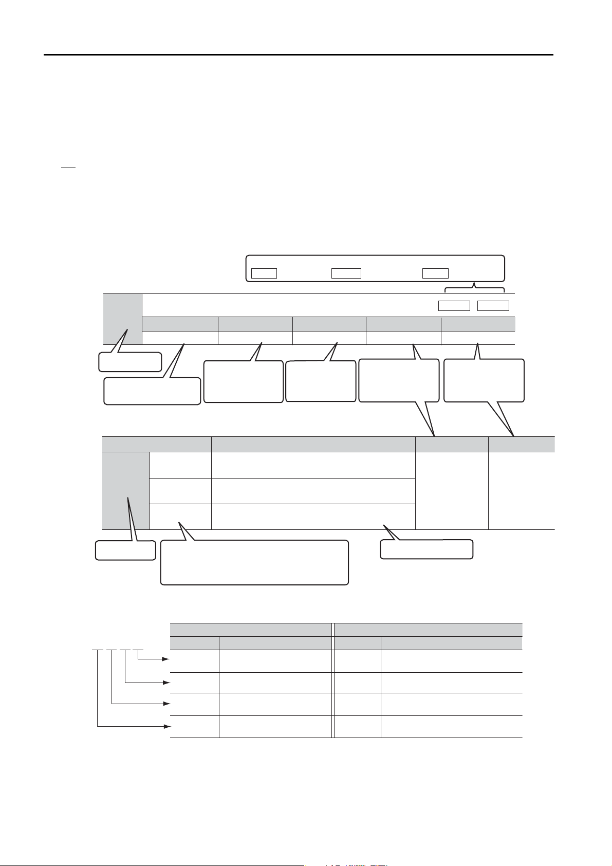
Outline of Manual
The contents of the chapters of this manual are described in the following table.
When you use the SERVOPACK, read this manual and the relevant product manual given in the following table.
Σ
-7S SERVOPACK with
Item
The Σ-7 Series – 1.1
Product Introduction 1.1 –
Interpreting the Nameplates – 1.2
Part Names – 1.3
Model Designations 1.2 –
Basic Information
on SERVOPACKs
Selecting a SERVOPACK
SERVOPACK Installation – Chapter 3
Wiring and Connecting SERVOPACKs – Chapter 4
Basic Functions That Require Setting before Operation – Chapter 5
Application Functions – Chapter 6
Trial Operation and Actual Operation – Chapter 7
Tuning – Chapter 8
Monitor
Combinations of SERVOPACKs and Servomotors
Functions 1.4 –
Restrictions 1.5 –
SigmaWin+ 1.6 –
Combining the SERVOPACKs with MPSeries Machine Controllers and the
MPE720 Engineering Tool
Ratings 2.1 –
SERVOPACK Overload Protection Characteristics
Specifications 2.3 –
Block Diagrams – 2.2
External Dimensions – 2.3
Examples of Standard Connections
between SERVOPACKs and Peripheral
Devices
Monitoring Product Information – 9.1
Monitoring SERVOPACK Status – 9.2
Monitoring Machine Operation Status and
Signal Waveforms
Monitoring Product Life – 9.4
This
Manual
–1.5
1.7 –
2.2 –
–2.4
3.7, 4.5 9.3
Communications References Product
MECHATROLINK-III
Manual
(Manual No.: SIEP S800001 28)
Continued on next page.
iii
Page 4

Continued from previous page.
Σ
-7S SERVOPACK with
Item
This
Manual
Communications References Product
MECHATROLINK-III
(Manual No.: SIEP S800001 28)
Fully-Closed Loop Control – Chapter 10
Safety Function – Chapter 11
Introduction 3.1 –
Input Signal Connections 3.2 –
Pressure Feedback Control
Operation Patterns for Pressure Feedback
Control
Changing from Torque Control to Pressure
Feedback Control
3.3 –
3.4 –
Control Block Diagrams 3.5 –
Setup Procedure 3.6 –
Monitoring 3.7 –
Introduction 4.1 –
Speed/Torque
(Pressure) Table
Operation
Operation Patterns for Speed/Torque (Pressure) Table Operation
Table Parameter Settings for Speed/Torque
(Pressure) Table Operation
4.2 –
4.3 –
Operating Procedure 4.4 –
Monitoring 4.5 –
Inspections and Part Replacement – 12.1
Alarm Displays
List of Alarms
Troubleshooting Alarms
5.1.1,
5.2.1
5.1.2,
5.2.2
5.1.3,
5.2.3
Resetting Alarms – 12.2.3
Display Alarm History – 12.2.4
Clearing the Alarm History – 12.2.5
Maintenance
Resetting Alarms Detected in Option
Modules
– 12.2.6
Resetting Motor Type Alarms – 12.2.7
Warning Displays
List of Warnings
Troubleshooting Warnings
Monitoring Communications Data during
Alarms or Warnings
Troubleshooting Based on the Operation
and Conditions of the Servomotor
5.1.4,
5.2.4
5.1.5,
5.2.5
5.1.6,
5.2.6
–12.4
5.1.7,
5.2.7
Interpreting the Parameter Lists 6.1 –
6.2.1,
6.3.1
6.2.2,
6.3.2
6.2.3,
6.3.3
Parameter Lists
List of Servo Parameters
List of MECHATROLINK-III Common
Parameters
Parameter Recording Table
Appendices – Chapter 14
Manual
–
–
–
–
–
–
–
–
–
–
iv
Page 5

Related Documents
Manuals Catalogs
System Components
Machine
Controller
and
Servo Drive
General
Catalog
MP3300
Catalog
Machine Controllers
Σ-7-Series
Catalog
Servo Drives
Machine Controllers
SERVOPACKs:
Σ-7S and Σ-7W
SERVOPACKs with Built-in Controllers:
Σ-7C
Servomotors
Other Documents
Built-in
Function
Manuals
Σ-7-Series
Σ-7S/Σ-7W
SERVOPACK
Product
Manuals
Σ-7-Series
Σ-7S/Σ-7W
SERVOPACK
Hardware Option
Product Manuals
Option
Module
User’s
Manuals
Σ-7-Series
Σ-7S/Σ-7W
SERVOPACK
FT/EX
Product Manuals
(This manual)
Option
Module
User’s
Manual
Σ-7-Series
Servomotor
Product
Manuals
Σ-7-Series
Σ-7C
SERVOPACK
Product Manual
Σ-7-Series
Σ-7C
SERVOPACK
Troubleshooting
Manual
Enclosed
Documents
Enclosed
Documents
Built-in
Function
Manuals
Enclosed
Documents
Σ-7-Series
Peripheral
Device
Selection
Manual
Σ-7-Series
Operation
Interface
Operation
Manuals
Σ-7-Series
MECHATROLINK
Communications
Command
Manuals
Programming
Manuals
Distributed
I/O Module
User’s
Manual
The relationships between the documents that are related to the Servo Drives are shown in the following
figure. The numbers in the figure correspond to the numbers in the table on the following pages. Refer
to these documents as required.
v
Page 6

Classification Document Name Document No. Description
Machine Controller
and Servo Drive
General Catalog
MP3300 Catalog
Σ-7-Series Catalog
Built-in Function
Manuals
Option Module
User’s Manuals
Machine Controller and
AC Servo Drive
Solutions Catalog
Machine Controller
MP3300
AC Servo Drives
Σ-7 Series
Σ-7-Series AC Servo Drive
Σ-7C SERVOPACK
Motion Control
User’s Manual
Machine Controller
MP3000 Series
Communications
User’s Manual
Machine Controller
MP2000 Series
Communication Module
User’s Manual
Machine Controller
MP2000 Series
262IF-01 FL-net
Communication Module
User’s Manual
Machine Controller
MP2000 Series
263IF-01 EtherNet/IP
Communication Module
User’s Manual
Machine Controller
MP2000 Series
I/O Module
User’s Manual
Machine Controller
MP2000 Series
Analog Input/Analog Output Module AI-01/AO-01
User’s Manual
Machine Controller
MP2000 Series
Counter Module CNTR-01
User’s Manual
KAEP S800001 22
KAEP C880725 03
KAEP S800001 23
SIEP S800002 03
SIEP C880725 12
SIEP C880700 04
SIEP C880700 36
SIEP C880700 39
SIEP C880700 34
SIEP C880700 26
SIEP C880700 27
Describes the features and application examples for combinations of
MP3000-Series Machine Controllers and Σ-7-Series AC Servo
Drives.
Provides detailed information on
MP3300 Machine Controllers,
including features and specifications.
Provides detailed information on Σ-
7-Series AC Servo Drives, including
features and specifications.
Provides detailed information on
the specifications, system configuration, and application methods of
the Motion Control Function Modules (SVD, SVC4, and SVR4) for Σ-
7-Series Σ-7C SERVOPACKs.
Provides detailed information on
the specifications, system configuration, and communications connection methods for the Ethernet
communications that are used with
MP3000-Series Machine Controllers and Σ-7-Series Σ-7C SERVOPAC Ks.
Provide detailed information on the
specifications and communications methods for the Communications Modules that can be mounted
to MP3000-Series Machine Controllers and Σ-7-Series Σ-7C
SERVOPACKs.
Provide detailed information on the
specifications and communications methods for the I/O Modules
that can be mounted to MP3000Series Machine Controllers and Σ-
7-Series Σ-7C SERVOPACKs.
Continued on next page.
vi
Page 7

Continued from previous page.
Classification Document Name Document No. Description
Enclosed Documents
Σ-7-Series AC Servo Drive
Σ-7S and Σ-7W SERVOPACK
Safety Precautions
Σ-V-Series/Σ-V-Series
for Large-Capacity Models/
Σ-7-Series
Safety Precautions
Option Module
Σ-V-Series/Σ-V-Series
for Large-Capacity Models/
Σ-7-Series
Installation Guide
Command Option Module
Σ-V-Series/Σ-V-Series
for Large-Capacity Models/
Σ-7-Series
Installation Guide
Fully-closed Module
TOMP C710828 00
TOBP C720829 00
TOBP C720829 01
TOBP C720829 03
Provides detailed information for
the safe usage of Σ-7-Series
SERVOPACKs.
Provides detailed information for
the safe usage of Option Modules.
Provides detailed procedures for
installing the Command Option
Module in a SERVOPACK.
Provides detailed procedures for
installing the Fully-closed Module in
a SERVOPACK.
Σ-7-Series
Σ-7C SERVOPACK
Product Manual
Σ-7-Series
Σ-7C SERVOPACK
Troubleshooting
Manual
Σ-V-Series/Σ-V-Series
for Large-Capacity Models/
Σ-7-Series
Installation Guide
Safety Module
Σ-V-Series/Σ-V-Series
for Large-Capacity Models/
Σ-7-Series
Installation Guide
INDEXER Module
Σ-V-Series/Σ-V-Series
for Large-Capacity Models/
Σ-7-Series
Installation Guide
DeviceNet Module
Σ-7-Series AC Servo Drive
Σ-7C SERVOPACK
Product Manual
Σ-7-Series AC Servo Drive
Σ-7C SERVOPACK
Troubleshooting Manual
TOBP C720829 06
TOBP C720829 02
TOBP C720829 07
SIEP S800002 04
SIEP S800002 07
Provides detailed procedures for
installing the Safety Module in a
SERVOPACK.
Provides detailed procedures for
installing the INDEXER Module in a
SERVOPACK.
Provides detailed procedures for
installing the DeviceNet Module in a
SERVOPACK.
Provides detailed information on
selecting Σ-7-Series Σ-7C SERVOPACKs; installing, connecting, setting, testing in trial operation, and
tuning Servo Drives; writing, monitoring, and maintaining programs;
and other information.
Provides detailed troubleshooting
information for Σ-7-Series Σ-7C
SERVOPACKs.
Continued on next page.
vii
Page 8

Classification Document Name Document No. Description
Σ-7-Series
Σ-7S/Σ-7W
SERVOPACK
Product Manuals
Σ-7-Series AC Servo Drive
Σ-7S SERVOPACK with
MECHATROLINK-III
Communications References
Product Manual
Σ-7-Series AC Servo Drive
Σ-7S SERVOPACK with
MECHATROLINK-II
Communications References
Product Manual
Σ-7-Series AC Servo Drive
Σ-7S SERVOPACK with
Analog Voltage/Pulse Train
References
Product Manual
Σ-7-Series AC Servo Drive
Σ-7S SERVOPACK
Command Option Attachable
Type with INDEXER Module
Product Manual
SIEP S800001 28
SIEP S800001 27
SIEP S800001 26
SIEP S800001 64
Continued from previous page.
Provide detailed information on
selecting Σ-7-Series SERVOPACKs and information on installing, connecting, setting, performing
trial operation for, tuning, and monitoring the Servo Drives.
Σ-7-Series
Σ-7S/Σ-7W
SERVOPACK with
Hardware Option
Specifications
Product Manuals
Σ-7-Series AC Servo Drive
Σ-7S SERVOPACK
Command Option Attachable
Type with DeviceNet Module
Product Manual
Σ-7-Series AC Servo Drive
Σ-7W SERVOPACK with
MECHATROLINK-III
Communications References
Product Manual
Σ-7-Series AC Servo Drive
Σ-7S/Σ-7W SERVOPACK with
Hardware Option Specifications
Dynamic Brake
Product Manual
Σ-7-Series AC Servo Drive
Σ-7W/Σ-7C SERVOPACK with
Hardware Option Specifications
HWBB Function
Product Manual
SIEP S800001 70
SIEP S800001 29
SIEP S800001 73
Provide detailed information on
Hardware Options for Σ-7-Series
SERVOPACKs.
SIEP S800001 72
Continued on next page.
viii
Page 9

Continued from previous page.
Classification Document Name Document No. Description
Σ-7-Series AC Servo Drive
Σ-7-Series
Σ-7S/Σ-7W SERVO-
PAC K
FT/EX
Product Manuals
Option Module
User’s Manual
Σ-7S SERVOPACK with
FT/EX Specification for Indexing
Application
Product Manual
Σ-7-Series AC Servo Drive
Σ-7S SERVOPACK with
FT/EX Specification for Tracking
Application
Product Manual
Σ-7-Series AC Servo Drive
Σ-7S SERVOPACK with
FT/EX Specification
for Application with Special Motor,
SGM7D Motor
Product Manual
Σ-7-Series AC Servo Drive
Σ-7S SERVOPACK with FT/EX
Specification for Press and
Injection Molding Application
Product Manual
Σ-7-Series AC Servo Drive
Σ-7S SERVOPACK with
FT/EX Specification
for Transfer and Alignment
Application
Product Manual
Σ-7-Series AC Servo Drive
Σ-7S SERVOPACK with
FT/EX Specification
for Torque/Force Assistance
for Conveyance Application
Product Manual
Σ-7-Series AC Servo Drive
Σ-7S SERVOPACK with
FT/EX Specification
for Cutting Application
Feed Shaft Motor
Product Manual
AC Servo Drives
Σ-V Series/Σ-V Series
for Large-Capacity Models/
Σ-7 Series
User’s Manual
Safety Module
SIEP S800001 84
SIEP S800001 89
SIEP S800001 91
This manual
(SIEP S800001 94)
SIEP S800001 95
SIEP S800002 09
SIEP S800002 10
SIEP C720829 06
Provide detailed information on the
FT/EX Option for Σ-7-Series
SERVOPACKs.
Provides details information
required for the design and maintenance of a Safety Module.
Enclosed Documents
AC Servo Drive
Rotary Servomotor
Safety Precautions
AC Servomotor
Linear Σ Series
Safety Precautions
TOBP C230260 00
TOBP C230800 00
Provides detailed information for
the safe usage of Rotary Servomotors and Direct Drive Servomotors.
Provides detailed information for
the safe usage of Linear Servomotors.
Continued on next page.
ix
Page 10

Continued from previous page.
Classification Document Name Document No. Description
Σ-7-Series AC Servo Drive
Rotary Servomotor
Product Manual
SIEP S800001 36
Σ-7-Series
Servomotor
Product Manuals
Σ-7-Series
Peripheral Device
Selection Manual
Σ-7-Series
MECHATROLINK
Communications
Command Manuals
Programming
Manuals
Σ-7-Series AC Servo Drive
Linear Servomotor
Product Manual
Σ-7-Series AC Servo Drive
Direct Drive Servomotor
Product Manual
Σ-7-Series AC Servo Drive
Peripheral Device
Selection Manual
Σ-7-Series AC Servo Drive
MECHATROLINK-II
Communications
Command Manual
Σ-7-Series AC Servo Drive
MECHATROLINK-III
Communications
Standard Servo Profile
Command Manual
Machine Controller
MP3000 Series
Ladder Programming
Manual
Machine Controller
MP3000 Series
Motion Programming
Manual
Machine Controller
MP2000/MP3000 Series
Engineering Tool
MPE720 Version 7
User’s Manual
SIEP S800001 37
SIEP S800001 38
SIEP S800001 32
SIEP S800001 30
SIEP S800001 31
SIEP C880725 13
SIEP C880725 14
SIEP C880761 03
Provide detailed information on
selecting, installing, and connecting
the Σ-7-Series Servomotors.
Describes the peripheral devices
for a Σ-7-Series Servo System.
Provides detailed information on
the MECHATROLINK-II communications commands that are used
for a Σ-7-Series Servo System.
Provides detailed information on
the MECHATROLINK-III communications standard servo profile commands that are used for a Σ-7-
Series Servo System.
Provides detailed information on
the ladder programming specifications and instructions for MP3000Series Machine Controllers and Σ-
7-Series Σ-7C SERVOPACKs.
Provides detailed information on
the motion programming and
sequence programming specifications and instructions for MP3000Series Machine Controllers and Σ-
7-Series Σ-7C SERVOPACKs.
Describes in detail how to operate
MPE720 version 7.
Σ-7-Series
Operation Interface
Operating Manuals
Distributed
I/O Module
User’s Manuals
Σ-7-Series AC Servo Drive
Digital Operator
Operating Manual
Servo Drive
AC
Engineering Tool
SigmaWin+
Operation Manual
MECHATROLINK-III
Compatible I/O Module
User’s Manual
SIEP S800001 33
SIET S800001 34
SIEP C880781 04
Describes the operating procedures for a Digital Operator for a
Σ-7
-Series Servo System.
Provides detailed operating procedures for the SigmaWin+ Engineering Tool for a Σ-7-Series Servo
System.
Describes the functions, specifications, operating methods, and
MECHATROLINK-III communications for the Remote I/O Modules
for MP2000/MP3000-Series
Machine Controllers.
x
Page 11

Using This Manual
Technical Terms Used in This Manual
The following terms are used in this manual.
Ter m Meaning
Servomotor A Σ-7-Series Rotary Servomotor, Direct Drive Servomotor, or Linear Servomotor.
A generic term used for a Σ-7-Series Rotary Servomotor (SGMMV, SGM7J, SGM7A, SGM7P,
Rotary Servomotor
Linear Servomotor
SERVOPACK
Servo Drive
Servo System
servo ON
servo OFF
base block (BB)
servo lock
Main Circuit Cable
SigmaWin+
or SGM7G) or a Direct Drive Servomotor (SGM7E, SGM7F, SGMCV, or SGMCS).
The descriptions will specify when Direct Drive Servomotors are excluded.
A generic term used for a Σ-7-Series Linear Servomotor (SGLG, SGLF, or SGLT).
A Σ-7-Series Σ-7S Servo Amplifier with MECHATROLINK-III Communications References.
The combination of a Servomotor and SERVOPACK.
A servo control system that includes the combination of a Servo Drive with a host controller
and peripheral devices.
Supplying power to the motor.
Not supplying power to the motor.
Shutting OFF the power supply to the motor by shutting OFF the base current to the power
transistor in the SERVOPACK.
A state in which the motor is stopped and is in a position loop with a position reference of 0.
One of the cables that connect to the main circuit terminals, including the Main Circuit Power
Supply Cable, Control Power Supply Cable, and Servomotor Main Circuit Cable.
The Engineering Tool for setting up and tuning Servo Drives or a computer in which the Engineering Tool is installed.
Differences in Terms for Rotary Servomotors and Linear Servomotors
There are differences in the terms that are used for Rotary Servomotors and Linear Servomotors.
This manual primarily describes Rotary Servomotors. If you are using a Linear Servomotor, you
need to interpret the terms as given in the following table.
Rotary Servomotor Linear Servomotor
torque force
moment of inertia
rotation movement
forward rotation and reverse rotation forward movement and reverse movement
CW and CCW pulse trains forward and reverse pulse trains
rotary encoder linear encoder
absolute rotary encoder absolute linear encoder
incremental rotary encoder incremental linear encoder
unit: min
unit: Nmunit: N
-1
mass
unit: mm/s
xi
Page 12
Pn100
Speed Loop Gain
Setting Range
10 to 20,000 0.1 Hz 400 Immediately
Setting Unit Default Setting When Enabled
Classication
Tuning
(default setting)
Use the encoder according to encoder specications.
Use the encoder as an incremental encoder.
Use the encoder as a single-turn absolute encoder.
This is the setting range
for the parameter.
Parameter
number
This column explains the
selections for the function.
Position
Torque
The control methods for which the parameters apply are given.
Speed
: Speed control : Position control : Torque control
This is the
parameter setting
before shipment.
This is when any
change made to the
parameter will
become effective.
This is the parameter
classication.
This is the minimum
unit (setting increment)
that you can set for
the parameter.
Position
Speed
Parameter Meaning When Enabled Classication
Pn002
n.
0
After startup Setup
n.1
n.2
Parameter
number
The notation “n.” indicates a parameter for
selecting functions.
Each
indicates the setting for one digit.
The notation shown here means that the third digit
from the right is set to 2.
• Parameters for Selecting Functions
Notation Examples for Pn002
Pn002 =
n.
X
Indicates the rst digit from
the right in Pn002.
Pn002 =
n.
1
Indicates that the rst digit from
the right in Pn002 is set to 1.
Pn002 =
n.
X
Indicates the second digit
from the right in Pn002.
Pn002 =
n.
1
Indicates that the second digit from
the right in Pn002 is set to 1.
Pn002 =
n.
X
Indicates the third digit from
the right in Pn002.
Pn002 =
n.
1
Indicates that the third digit from
the right in Pn002 is set to 1.
Pn002 =
n.X
Indicates the fourth digit from
the right in Pn002.
Pn002 =
n.1
Indicates that the fourth digit from
the right in Pn002 is set to 1.
n.0 0 0 0
Notation
Digit Notation Numeric Value Notation
Meaning Notation Meaning
Notation Used in this Manual
Notation for Reverse Signals
The names of reverse signals (i.e., ones that are valid when low) are written with a forward slash (/)
before the signal abbreviation.
Notation Example
BK
is written as /BK.
Notation for Parameters
The notation depends on whether the parameter requires a numeric setting (parameter for numeric
setting) or requires the selection of a function (parameter for selecting functions).
•
Parameters for Numeric Settings
Notation Example
xii
Engineering Tools Used in This Manual
This manual uses the interfaces of the SigmaWin+ for descriptions.
Page 13
Trademarks
Important
Term
Example
Information
• MECHATROLINK is a trademark of the MECHATROLINK Members Association.
• QR code is a trademark of Denso Wave Inc.
• Other product names and company names are the trademarks or registered trademarks of the
respective company. “TM” and the
® mark do not appear with product or company names in this
manual.
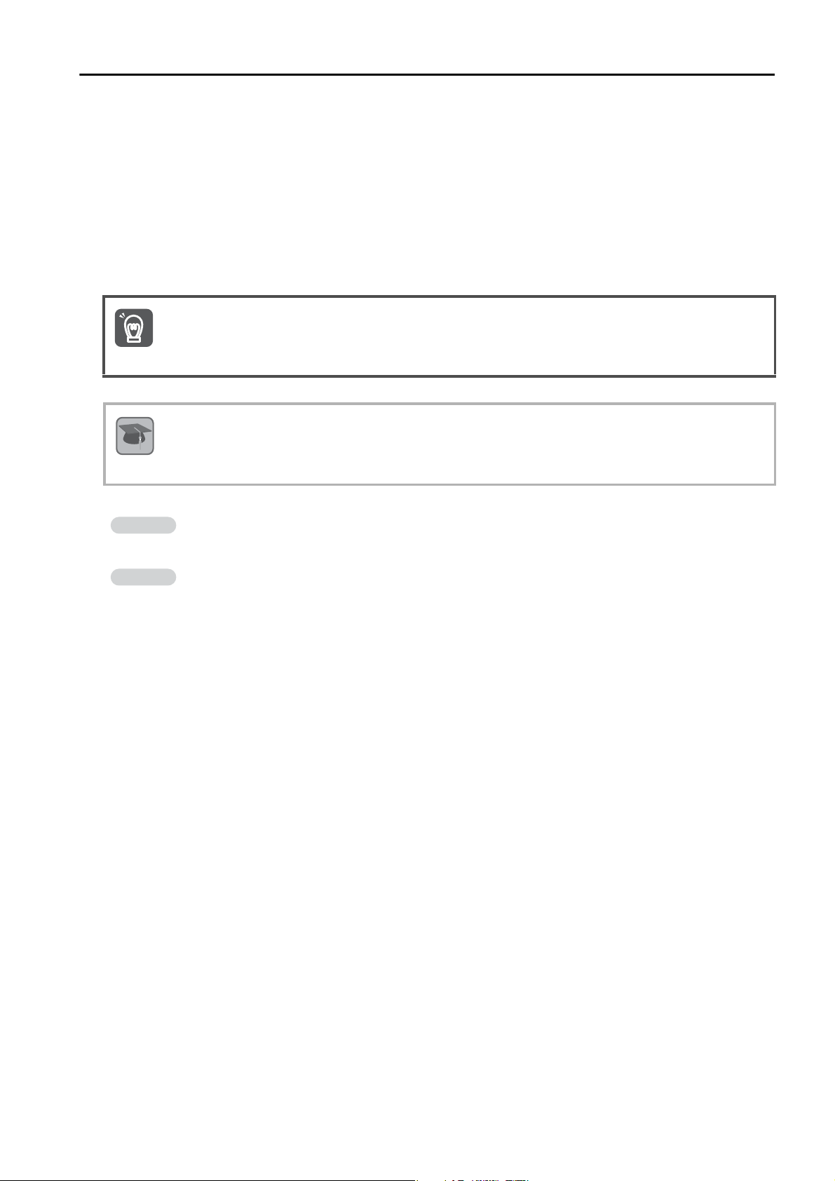
Visual Aids
The following aids are used to indicate certain types of information for easier reference.
Indicates precautions or restrictions that must be observed.
Also indicates alarm displays and other precautions that will not result in machine damage.
Indicates definitions of difficult terms or terms that have not been previously explained in this manual.
Indicates operating or setting examples.
Indicates supplemental information to deepen understanding or useful information.
xiii
Page 14
DANGER
WARNING
CAUTION
NOTICE
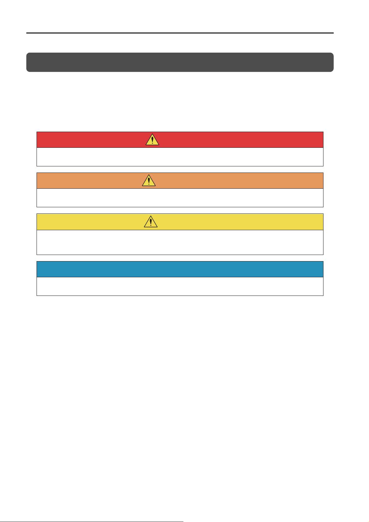
Safety Precautions
Safety Information
To prevent personal injury and equipment damage in advance, the following signal words are used
to indicate safety precautions in this document. The signal words are used to classify the hazards
and the degree of damage or injury that may occur if a product is used incorrectly. Information
marked as shown below is important for safety. Always read this information and heed the precautions that are provided.
Indicates precautions that, if not heeded, are likely to result in loss of life, serious injury, or fire.
Indicates precautions that, if not heeded, could result in loss of life, serious injury, or fire.
Indicates precautions that, if not heeded, could result in relatively serious or minor injury, or in
fire.
Indicates precautions that, if not heeded, could result in property damage.
xiv
Page 15

Safety Precautions That Must Always Be Observed
DANGER
WARNING
CAUTION
General Precautions
Read and understand this manual to ensure the safe usage of the product.
Keep this manual in a safe, convenient place so that it can be referred to whenever necessary.
Make sure that it is delivered to the final user of the product.
Do not remove covers, cables, connectors, or optional devices while power is being supplied to
the SERVOPACK.
There is a risk of electric shock, operational failure of the product, or burning.
Use a power supply with specifications (number of phases, voltage, frequency, and AC/DC
type) that are appropriate for the product.
There is a risk of burning, electric shock, or fire.
Connect the ground terminals on the SERVOPACK and Servomotor to ground poles according
to local electrical codes (100 Ω or less for a SERVOPACK with a 100-VAC or 200-VAC power
supply, and 10 Ω or less for a SERVOPACK with a 400-VAC power supply).
There is a risk of electric shock or fire.
Do not attempt to disassemble, repair, or modify the product.
There is a risk of fire or failure.
The warranty is void for the product if you disassemble, repair, or modify it.
The SERVOPACK heat sinks, regenerative resistors, External Dynamic Brake Resistors, Servo-
motors, and other components can be very hot while power is ON or soon after the power is
turned OFF. Implement safety measures, such as installing covers, so that hands and parts
such as cables do not come into contact with hot components.
There is a risk of burn injury.
For a 24-VDC power supply, use a power supply device with double insulation or reinforced
insulation.
There is a risk of electric shock.
Do not damage, pull on, apply excessive force to, place heavy objects on, or pinch cables.
There is a risk of failure, damage, or electric shock.
The person who designs the system that uses the hard wire base block safety function must
have a complete knowledge of the related safety standards and a complete understanding of
the instructions in this document.
There is a risk of injury, product damage, or machine damage.
Do not use the product in an environment that is subject to water, corrosive gases, or flamma-
ble gases, or near flammable materials.
There is a risk of electric shock or fire.
xv
Page 16

NOTICE
CAUTION
NOTICE
CAUTION
Do not attempt to use a SERVOPACK or Servomotor that is damaged or that has missing parts.
Install external emergency stop circuits that shut OFF the power supply and stops operation
immediately when an error occurs.
In locations with poor power supply conditions, install the necessary protective devices (such as
AC reactors) to ensure that the input power is supplied within the specified voltage range.
There is a risk of damage to the SERVOPACK.
Use a Noise Filter to minimize the effects of electromagnetic interference.
Electronic devices used near the SERVOPACK may be affected by electromagnetic interference.
Always use a Servomotor and SERVOPACK in one of the specified combinations.
Do not touch a SERVOPACK or Servomotor with wet hands.
There is a risk of product failure.
Storage Precautions
Do not place an excessive load on the product during storage. (Follow all instructions on the
packages.)
There is a risk of injury or damage.
Do not install or store the product in any of the following locations.
• Locations that are subject to direct sunlight
• Locations that are subject to ambient temperatures that exceed product specifications
• Locations that are subject to relative humidities that exceed product specifications
• Locations that are subject to condensation as the result of extreme changes in temperature
• Locations that are subject to corrosive or flammable gases
• Locations that are near flammable materials
• Locations that are subject to dust, salts, or iron powder
• Locations that are subject to water, oil, or chemicals
• Locations that are subject to vibration or shock that exceeds product specifications
• Locations that are subject to radiation
If you store or install the product in any of the above locations, the product may fail or be damaged.
Transportation Precautions
Transport the product in a way that is suitable to the mass of the product.
Do not use the eyebolts on a SERVOPACK or Servomotor to move the machine.
There is a risk of damage or injury.
When you handle a SERVOPACK or Servomotor, be careful of sharp parts, such as the corners.
There is a risk of injury.
Do not place an excessive load on the product during transportation. (Follow all instructions on
the packages.)
There is a risk of injury or damage.
xvi
Page 17

NOTICE
Do not hold onto the front cover or connectors when you move a SERVOPACK.
CAUTION
There is a risk of the SERVOPACK falling.
A SERVOPACK or Servomotor is a precision device. Do not drop it or subject it to strong shock.
There is a risk of failure or damage.
Do not subject connectors to shock.
There is a risk of faulty connections or damage.
If disinfectants or insecticides must be used to treat packing materials such as wooden frames,
plywood, or pallets, the packing materials must be treated before the product is packaged, and
methods other than fumigation must be used.
Example: Heat treatment, where materials are kiln-dried to a core temperature of 56°C for 30
minutes or more.
If the electronic products, which include stand-alone products and products installed in machines,
are packed with fumigated wooden materials, the electrical components may be greatly damaged
by the gases or fumes resulting from the fumigation process. In particular, disinfectants containing
halogen, which includes chlorine, fluorine, bromine, or iodine can contribute to the erosion of the
capacitors.
Do not overtighten the eyebolts on a SERVOPACK or Servomotor.
If you use a tool to overtighten the eyebolts, the tapped holes may be damaged.
Installation Precautions
Install the Servomotor or SERVOPACK in a way that will support the mass given in technical
documents.
Install SERVOPACKs, Servomotors, regenerative resistors, and External Dynamic Brake Resis-
tors on nonflammable materials.
Installation directly onto or near flammable materials may result in fire.
Provide the specified clearances between the SERVOPACK and the control panel as well as
with other devices.
There is a risk of fire or failure.
Install the SERVOPACK in the specified orientation.
There is a risk of fire or failure.
Do not step on or place a heavy object on the product.
There is a risk of failure, damage, or injury.
Do not allow any foreign matter to enter the SERVOPACK or Servomotor.
There is a risk of failure or fire.
xvii
Page 18

NOTICE
DANGER
WARNING
Do not install or store the product in any of the following locations.
• Locations that are subject to direct sunlight
• Locations that are subject to ambient temperatures that exceed product specifications
• Locations that are subject to relative humidities that exceed product specifications
• Locations that are subject to condensation as the result of extreme changes in temperature
• Locations that are subject to corrosive or flammable gases
• Locations that are near flammable materials
• Locations that are subject to dust, salts, or iron powder
• Locations that are subject to water, oil, or chemicals
• Locations that are subject to vibration or shock that exceeds product specifications
• Locations that are subject to radiation
If you store or install the product in any of the above locations, the product may fail or be damaged.
Use the product in an environment that is appropriate for the product specifications.
If you use the product in an environment that exceeds product specifications, the product may fail
or be damaged.
A SERVOPACK or Servomotor is a precision device. Do not drop it or subject it to strong shock.
There is a risk of failure or damage.
Always install a SERVOPACK in a control panel.
Do not allow any foreign matter to enter a SERVOPACK or a Servomotor with a Cooling Fan and
do not cover the outlet from the Servomotor’s cooling fan.
There is a risk of failure.
Wiring Precautions
Do not change any wiring while power is being supplied.
There is a risk of electric shock or injury.
Wiring and inspections must be performed only by qualified engineers.
There is a risk of electric shock or product failure.
Check all wiring and power supplies carefully.
Incorrect wiring or incorrect voltage application to the output circuits may cause short-circuit failures. If a short-circuit failure occurs as a result of any of these causes, the holding brake will not
work. This could damage the machine or cause an accident that may result in death or injury.
Connect the AC and DC power supplies to the specified SERVOPACK terminals.
• Connect an AC power supply to the L1, L2, and L3 terminals and the L1C and L2C terminals on the
SERVOPACK.
• Connect a DC power supply to the B1/ and 2 terminals and the L1C and L2C terminals on the
SERVOPACK.
There is a risk of failure or fire.
If you use a SERVOPACK that supports a Dynamic Brake Option, connect an External Dynamic
Brake Resistor that is suitable for the machine and equipment specifications to the specified
terminals.
There is a risk of unexpected operation, machine damage, burning, or injury when an emergency
stop is performed.
xviii
Page 19

CAUTION
Wait for at least six minutes after turning OFF the power supply (with a SERVOPACK for a 100-
NOTICE
VAC power supply input, wait for at least nine minutes) and then make sure that the CHARGE
indicator is not lit before starting wiring or inspection work. Do not touch the power supply terminals while the CHARGE lamp is lit after turning OFF the power supply because high voltage
may still remain in the SERVOPACK.
There is a risk of electric shock.
Observe the precautions and instructions for wiring and trial operation precisely as described in
this document.
Failures caused by incorrect wiring or incorrect voltage application in the brake circuit may cause
the SERVOPACK to fail, damage the equipment, or cause an accident resulting in death or injury.
Check the wiring to be sure it has been performed correctly.
Connectors and pin layouts are sometimes different for different models. Always confirm the pin
layouts in technical documents for your model before operation.
There is a risk of failure or malfunction.
Connect wires to power supply terminals and motor connection terminals securely with the
specified methods and tightening torque.
Insufficient tightening may cause wires and terminal blocks to generate heat due to faulty contact,
possibly resulting in fire.
Use shielded twisted-pair cables or screened unshielded multi-twisted-pair cables for I/O Sig-
nal Cables and Encoder Cables.
Observe the following precautions when wiring the SERVOPACK’s main circuit terminals.
• Turn ON the power supply to the SERVOPACK only after all wiring, including the main circuit terminals, has been completed.
• If a connector is used for the main circuit terminals, remove the main circuit connector from the SERVOPACK before you wire it.
• Insert only one wire per insertion hole in the main circuit terminals.
• When you insert a wire, make sure that the conductor wire (e.g., whiskers) does not come into con-
tact with adjacent wires.
Install molded-case circuit breakers and other safety measures to provide protection against
short circuits in external wiring.
There is a risk of fire or failure.
Whenever possible, use the Cables specified by Yaskawa.
If you use any other cables, confirm the rated current and application environment of your model
and use the wiring materials specified by Yaskawa or equivalent materials.
Securely tighten cable connector screws and lock mechanisms.
Insufficient tightening may result in cable connectors falling off during operation.
Do not bundle power lines (e.g., the Main Circuit Cable) and low-current lines (e.g., the I/O Sig-
nal Cables or Encoder Cables) together or run them through the same duct. If you do not place
power lines and low-current lines in separate ducts, separate them by at least 30 cm.
If the cables are too close to each other, malfunctions may occur due to noise affecting the low-current lines.
Install a battery at either the host controller or on the Encoder Cable.
If you install batteries both at the host controller and on the Encoder Cable at the same time, you
will create a loop circuit between the batteries, resulting in a risk of damage or burning.
When connecting a battery, connect the polarity correctly.
There is a risk of battery rupture or encoder failure.
xix
Page 20

WARNING
CAUTION
Operation Precautions
Before starting operation with a machine connected, change the settings of the switches and
parameters to match the machine.
Unexpected machine operation, failure, or personal injury may occur if operation is started before
appropriate settings are made.
Do not radically change the settings of the parameters.
There is a risk of unstable operation, machine damage, or injury.
Install limit switches or stoppers at the ends of the moving parts of the machine to prevent
unexpected accidents.
There is a risk of machine damage or injury.
For trial operation, securely mount the Servomotor and disconnect it from the machine.
There is a risk of injury.
Forcing the motor to stop for overtravel is disabled when the Jog (Fn002), Origin Search
(Fn003), or Easy FFT (Fn206) utility function is executed. Take necessary precautions.
There is a risk of machine damage or injury.
When an alarm occurs, the Servomotor will coast to a stop or stop with the dynamic brake
according to the SERVOPACK Option specifications and settings. The coasting distance will
change with the moment of inertia of the load and the resistance of the External Dynamic Brake
Resistor. Check the coasting distance during trial operation and implement suitable safety measures on the machine.
Do not enter the machine’s range of motion during operation.
There is a risk of injury.
Do not touch the moving parts of the Servomotor or machine during operation.
There is a risk of injury.
Design the system to ensure safety even when problems, such as broken signal lines, occur.
For example, the P-OT and N-OT signals are set in the default settings to operate on the safe
side if a signal line breaks. Do not change the polarity of this type of signal.
When overtravel occurs, the power supply to the motor is turned OFF and the brake is released.
If you use the Servomotor to drive a vertical load, set the Servomotor to enter a zero-clamped
state after the Servomotor stops. Also, install safety devices (such as an external brake or
counterweight) to prevent the moving parts of the machine from falling.
Always turn OFF the servo before you turn OFF the power supply. If you turn OFF the main cir-
cuit power supply or control power supply during operation before you turn OFF the servo, the
Servomotor will stop as follows:
• If you turn OFF the main circuit power supply during operation without turning OFF the servo, the
Servomotor will stop abruptly with the dynamic brake.
• If you turn OFF the control power supply without turning OFF the servo, the stopping method that is
used by the Servomotor depends on the model of the SERVOPACK. For details, refer to the manual
for the SERVOPACK.
• If you use a SERVOPACK with the Dynamic Brake Hardware Option, the Servomotor stopping methods will be different from the stopping methods used without the Option or with other Hardware
Options. For details, refer to the following manual.
Σ-7-Series Σ-7S/Σ-7W SERVOPACK with Dynamic Brake Hardware Option Specifications Product Manual
(Manual No.: SIEP S800001 73)
Do not use the dynamic brake for any application other than an emergency stop.
There is a risk of failure due to rapid deterioration of elements in the SERVOPACK and the risk of
unexpected operation, machine damage, burning, or injury.
xx
Page 21

NOTICE
When you adjust the gain during system commissioning, use a measuring instrument to monitor
DANGER
WARNING
CAUTION
NOTICE
the torque waveform and speed waveform and confirm that there is no vibration.
If a high gain causes vibration, the Servomotor will be damaged quickly.
Do not frequently turn the power supply ON and OFF. After you have started actual operation,
allow at least one hour between turning the power supply ON and OFF (as a guideline).
Do not use the product in applications that require the power supply to be turned ON and OFF
frequently.
The elements in the SERVOPACK will deteriorate quickly.
An alarm or warning may occur if communications are performed with the host controller while
the SigmaWin+ or Digital Operator is operating.
If an alarm or warning occurs, it may interrupt the current process and stop the system.
After you complete trial operation of the machine and facilities, use the SigmaWin+ to back up
the settings of the SERVOPACK parameters. You can use them to reset the parameters after
SERVOPACK replacement.
If you do not copy backed up parameter settings, normal operation may not be possible after a
faulty SERVOPACK is replaced, possibly resulting in machine or equipment damage.
Maintenance and Inspection Precautions
Do not change any wiring while power is being supplied.
There is a risk of electric shock or injury.
Wiring and inspections must be performed only by qualified engineers.
There is a risk of electric shock or product failure.
Wait for at least six minutes after turning OFF the power supply (with a SERVOPACK for a 100-
VAC power supply input, wait for at least nine minutes) and then make sure that the CHARGE
indicator is not lit before starting wiring or inspection work. Do not touch the power supply terminals while the CHARGE lamp is lit after turning OFF the power supply because high voltage
may still remain in the SERVOPACK.
There is a risk of electric shock.
Before you replace a SERVOPACK, back up the settings of the SERVOPACK parameters. Copy
the backed up parameter settings to the new SERVOPACK and confirm that they were copied
correctly.
If you do not copy backed up parameter settings or if the copy operation is not completed normally,
normal operation may not be possible, possibly resulting in machine or equipment damage.
Discharge all static electricity from your body before you operate any of the buttons or switches
inside the front cover of the SERVOPACK.
There is a risk of equipment damage.
xxi
Page 22

DANGER
WARNING
CAUTION
Troubleshooting Precautions
If the safety device (molded-case circuit breaker or fuse) installed in the power supply line oper-
ates, remove the cause before you supply power to the SERVOPACK again. If necessary, repair
or replace the SERVOPACK, check the wiring, and remove the factor that caused the safety
device to operate.
There is a risk of fire, electric shock, or injury.
The product may suddenly start to operate when the power supply is recovered after a momen-
tary power interruption. Design the machine to ensure human safety when operation restarts.
There is a risk of injury.
When an alarm occurs, remove the cause of the alarm and ensure safety. Then reset the alarm
or turn the power supply OFF and ON again to restart operation.
There is a risk of injury or machine damage.
If the Servo ON signal is input to the SERVOPACK and an alarm is reset, the Servomotor may
suddenly restart operation. Confirm that the servo is OFF and ensure safety before you reset an
alarm.
There is a risk of injury or machine damage.
Always insert a magnetic contactor in the line between the main circuit power supply and the
main circuit power supply terminals on the SERVOPACK so that the power supply can be shut
OFF at the main circuit power supply.
If a magnetic contactor is not connected when the SERVOPACK fails, a large current may flow,
possibly resulting in fire.
If an alarm occurs, shut OFF the main circuit power supply.
There is a risk of fire due to a regenerative resistor overheating as the result of regenerative transistor failure.
Install a ground fault detector against overloads and short-circuiting or install a molded-case
circuit breaker combined with a ground fault detector.
There is a risk of SERVOPACK failure or fire if a ground fault occurs.
The holding brake on a Servomotor will not ensure safety if there is the possibility that an exter-
nal force (including gravity) may move the current position and create a hazardous situation
when power is interrupted or an error occurs. If an external force may cause movement, install
an external braking mechanism that ensures safety.
xxii
Disposal Precautions
When disposing of the product, treat it as ordinary industrial waste. However, local ordinances
and national laws must be observed. Implement all labeling and warnings as a final product as
required.
Page 23

General Precautions
Figures provided in this document are typical examples or conceptual representations. There
may be differences between them and actual wiring, circuits, and products.
The products shown in illustrations in this document are sometimes shown without covers or
protective guards. Always replace all covers and protective guards before you use the product.
If you need a new copy of this document because it has been lost or damaged, contact your
nearest Yaskawa representative or one of the offices listed on the back of this document.
This document is subject to change without notice for product improvements, specifications
changes, and improvements to the manual itself.
We will update the document number of the document and issue revisions when changes are
made.
Any and all quality guarantees provided by Yaskawa are null and void if the customer modifies
the product in any way. Yaskawa disavows any responsibility for damages or losses that are
caused by modified products.
xxiii
Page 24

Warranty
Details of Warranty
Warranty Period
The warranty period for a product that was purchased (hereinafter called the “delivered product”) is
one year from the time of delivery to the location specified by the customer or 18 months from the
time of shipment from the Yaskawa factory, whichever is sooner.
Warranty Scope
Yaskawa shall replace or repair a defective product free of charge if a defect attributable to
Yaskawa occurs during the above warranty period.
This warranty does not cover defects caused by the delivered product reaching the end of its service life and replacement of parts that require replacement or that have a limited service life.
This warranty does not cover failures that result from any of the following causes.
• Improper handling, abuse, or use in unsuitable conditions or in environments not described in
product catalogs or manuals, or in any separately agreed-upon specifications
• Causes not attributable to the delivered product itself
• Modifications or repairs not performed by Yaskawa
• Use of the delivered product in a manner in which it was not originally intended
• Causes that were not foreseeable with the scientific and technological understanding at the time
of shipment from Yaskawa
• Events for which Yaskawa is not responsible, such as natural or human-made disasters
Limitations of Liability
• Yaskawa shall in no event be responsible for any damage or loss of opportunity to the customer
that arises due to failure of the delivered product.
• Yaskawa shall not be responsible for any programs (including parameter settings) or the results of
program execution of the programs provided by the user or by a third party for use with programmable Yaskawa products.
• The information described in product catalogs or manuals is provided for the purpose of the customer purchasing the appropriate product for the intended application. The use thereof does not
guarantee that there are no infringements of intellectual property rights or other proprietary rights
of Yaskawa or third parties, nor does it construe a license.
• Yaskawa shall not be responsible for any damage arising from infringements of intellectual property rights or other proprietary rights of third parties as a result of using the information described
in catalogs or manuals.
xxiv
Page 25

Suitability for Use
• It is the customer’s responsibility to confirm conformity with any standards, codes, or regulations
that apply if the Yaskawa product is used in combination with any other products.
• The customer must confirm that the Yaskawa product is suitable for the systems, machines, and
equipment used by the customer.
• Consult with Yaskawa to determine whether use in the following applications is acceptable. If use
in the application is acceptable, use the product with extra allowance in ratings and specifications, and provide safety measures to minimize hazards in the event of failure.
• Outdoor use, use involving potential chemical contamination or electrical interference, or use
in conditions or environments not described in product catalogs or manuals
• Nuclear energy control systems, combustion systems, railroad systems, aviation systems,
vehicle systems, medical equipment, amusement machines, and installations subject to separate industry or government regulations
• Systems, machines, and equipment that may present a risk to life or property
• Systems that require a high degree of reliability, such as systems that supply gas, water, or
electricity, or systems that operate continuously 24 hours a day
• Other systems that require a similar high degree of safety
• Never use the product for an application involving serious risk to life or property without first
ensuring that the system is designed to secure the required level of safety with risk warnings and
redundancy, and that the Yaskawa product is properly rated and installed.
• The circuit examples and other application examples described in product catalogs and manuals
are for reference. Check the functionality and safety of the actual devices and equipment to be
used before using the product.
• Read and understand all use prohibitions and precautions, and operate the Yaskawa product
correctly to prevent accidental harm to third parties.
Specifications Change
The names, specifications, appearance, and accessories of products in product catalogs and
manuals may be changed at any time based on improvements and other reasons. The next editions of the revised catalogs or manuals will be published with updated code numbers. Consult
with your Yaskawa representative to confirm the actual specifications before purchasing a product.
xxv
Page 26

Compliance with UL Standards, EU Directives, and Other Safety Standards
Certification marks for the standards for which the product has been certified by certification bodies
are shown on nameplate. Products that do not have the marks are not certified for the standards.
North American Safety Standards (UL)
Product Model North American Safety Standards (UL File No.)
SERVOPACKs SGD7S
• SGMMV
Rotary
Servomotors
Direct Drive Servomotors
Linear
Servomotors
*1. Certification is pending.
*2. SGM7F-B, -C, and -D: Certified; SGM7F-A: Certification is pending.
• SGM7A
• SGM7J
• SGM7P
• SGM7G
• SGM7E
• SGM7F
• SGMCV
• SGLGW
• SGLFW
• SGLFW2
• SGLTW
*1
*2
*1
UL 61800-5-1 (E147823)
CSA C22.2 No.274
UL 1004-1
UL 1004-6
(E165827)
UL 1004-1
UL 1004-6
(E165827)
UL 1004
(E165827)
xxvi
Page 27

European Directives
Product Model EU Directive Harmonized Standards
Machinery Directive
2006/42/EC
SERVOPACKs
SGD7S
EMC Directive
2014/30/EU
Low Voltage Directive
2014/35/EU
EMC Directive
SGMMV
2004/104/EC
Low Voltage Directive
2006/95/EC
Rotary
Servomotors
• SGM7J
• SGM7A
EMC Directive
2014/30/EU
• SGM7P
• SGM7G
Low Voltage Directive
2014/35/EU
*1
*1
B, C,
D, E
EMC Directive
2004/108/EC
Low Voltage Directive
2006/95/EC
Direct Drive
Servomotors
• SGM7E
• SGM7F
• SGMCV
• SGMCS-
(Small-Capacity, Coreless
Servomotors)
Linear
Servomotors
• SGLF
• SGLFW2
• SGLT
*1. Certification is pending.
*2. Certification is pending for the SGM7F and SGMCV. No application has been made for SGMCS certification.
*3. No application has been made for SGMCS certification.
Note: 1. We declared the CE Marking based on the harmonized standards in the above table.
2. These products are for industrial use. In home environments, these products may cause electromagnetic interference and additional noise reduction measures may be necessary.
• SGLG
EMC Directive
2004/108/EC
Low Voltage Directive
2006/95/EC
EN ISO13849-1: 2015
EN 55011 group 1, class A
EN 61000-6-2
EN 61000-6-4
EN 61800-3 (Category C2, Second
environment)
EN 50178
EN 61800-5-1
EN 55011 group 1, class A
EN 61000-6-2
EN 61800-3
EN 60034-1
EN 60034-5
EN 55011 group 1, class A
EN 61000-6-2
EN 61000-6-4
EN 61800-3 (Category C2, Second
environment)
EN 60034-1
EN 60034-5
EN 55011 group 1, class A
EN 61000-6-2
EN 61000-6-4
EN 61800-3
*2
*3
EN 60034-1
EN 60034-5
EN 55011 group 1, class A
EN 61000-6-2
EN 61000-6-4
EN 60034-1
Safety Standards
Product Model Safety Standards Standards
EN ISO13849-1: 2015
IEC 60204-1
IEC 61508 series
IEC 62061
IEC 61800-5-2
SERVOPACKs SGD7S
Safety of Machinery
Functional Safety
EMC IEC 61326-3-1
xxvii
Page 28

Safety Parameters
Item Standards Performance Level
Safety Integrity Level
Probability of Dangerous Failure per Hour
Performance Level EN ISO 13849-1 PLe (Category 3)
Mean Time to Dangerous Failure of Each Channel EN ISO 13849-1 MTTFd: High
Average Diagnostic Coverage EN ISO 13849-1 DCavg: Medium
Stop Category IEC 60204-1 Stop category 0
Safety Function IEC 61800-5-2 STO
Mission Time IEC 61508 10 years
Hardware Fault Tolerance IEC 61508 HFT = 1
Subsystem IEC 61508 B
IEC 61508 SIL3
IEC 62061 SILCL3
IEC 61508
IEC 62061
PFH = 4.04×10
(4.04% of SIL3)
-9
[1/h]
xxviii
Page 29

1
Contents
About this Manual. . . . . . . . . . . . . . . . . . . . . . . . . . . . . . . . . . . . . . . . . . . . . . . . .iii
Outline of Manual . . . . . . . . . . . . . . . . . . . . . . . . . . . . . . . . . . . . . . . . . . . . . . . . .iii
Related Documents . . . . . . . . . . . . . . . . . . . . . . . . . . . . . . . . . . . . . . . . . . . . . . . v
Using This Manual . . . . . . . . . . . . . . . . . . . . . . . . . . . . . . . . . . . . . . . . . . . . . . . .xi
Safety Precautions . . . . . . . . . . . . . . . . . . . . . . . . . . . . . . . . . . . . . . . . . . . . . . . xiv
Warranty . . . . . . . . . . . . . . . . . . . . . . . . . . . . . . . . . . . . . . . . . . . . . . . . . . . . . . xxiv
Compliance with UL Standards, EU Directives, and Other Safety Standards . . xxvi
Basic Information on SERVOPACKs
2
1.1
1.2
1.3
1.4
1.5
1.6
1.7
Product Introduction . . . . . . . . . . . . . . . . . . . . . . . . . . . . . . . . . 1-2
Model Designations . . . . . . . . . . . . . . . . . . . . . . . . . . . . . . . . . . 1-3
1.2.1 Interpreting SERVOPACK Model Numbers with the FT40 Specification . . . . 1-3
1.2.2 Interpreting SERVOPACK Model Numbers with the FT41 Specification . . . . 1-4
1.2.3 Interpreting Servomotor Model Numbers. . . . . . . . . . . . . . . . . . . . . . . . . . . 1-4
Combinations of SERVOPACKs and Servomotors . . . . . . . . . . . 1-5
Functions . . . . . . . . . . . . . . . . . . . . . . . . . . . . . . . . . . . . . . . . . . 1-6
Restrictions . . . . . . . . . . . . . . . . . . . . . . . . . . . . . . . . . . . . . . . . 1-9
1.5.1 Function Application Restrictions . . . . . . . . . . . . . . . . . . . . . . . . . . . . . . . . 1-9
1.5.2 Restrictions on Specifications . . . . . . . . . . . . . . . . . . . . . . . . . . . . . . . . . . . 1-9
SigmaWin+ . . . . . . . . . . . . . . . . . . . . . . . . . . . . . . . . . . . . . . . . 1-10
Combining the SERVOPACKs with MP-Series Machine Controllers and the MPE720 Engineering Tool
SERVOPACK Ratings and Specifications
. . 1-11
3
2.1
2.2
2.3
Ratings . . . . . . . . . . . . . . . . . . . . . . . . . . . . . . . . . . . . . . . . . . . . 2-2
SERVOPACK Overload Protection Characteristics . . . . . . . . . . 2-5
Specifications. . . . . . . . . . . . . . . . . . . . . . . . . . . . . . . . . . . . . . . 2-6
Pressure Feedback Control
3.1
3.2
3.3
Introduction . . . . . . . . . . . . . . . . . . . . . . . . . . . . . . . . . . . . . . . . 3-3
Connecting Pressure Sensor Amplifiers. . . . . . . . . . . . . . . . . . . 3-4
3.2.1 FT40 . . . . . . . . . . . . . . . . . . . . . . . . . . . . . . . . . . . . . . . . . . . . . . . . . . . . . . 3-4
3.2.2 FT41 . . . . . . . . . . . . . . . . . . . . . . . . . . . . . . . . . . . . . . . . . . . . . . . . . . . . . . 3-4
Operation Patterns for Pressure Feedback Control. . . . . . . . . . 3-5
xxix
Page 30

4
3.4
3.5
3.6
3.7
Changing from Torque Control to Pressure Feedback Control . 3-6
3.4.1 Mode 2 Operation . . . . . . . . . . . . . . . . . . . . . . . . . . . . . . . . . . . . . . . . . . . .3-6
3.4.2 Mode 1 Operation . . . . . . . . . . . . . . . . . . . . . . . . . . . . . . . . . . . . . . . . . . . .3-6
Control Block Diagrams . . . . . . . . . . . . . . . . . . . . . . . . . . . . . . . 3-7
3.5.1 Pressure Feedback Control 2 (Pn458 = n.1) . . . . . . . . . . . . . . . . . . . .3-7
3.5.2 Pressure Feedback Control 1 (Pn458 = n.0) . . . . . . . . . . . . . . . . . . . .3-8
Setup Procedure . . . . . . . . . . . . . . . . . . . . . . . . . . . . . . . . . . . 3-10
3.6.1 Flowchart . . . . . . . . . . . . . . . . . . . . . . . . . . . . . . . . . . . . . . . . . . . . . . . . . .3-10
3.6.2 Disabling Tuning-Less Function . . . . . . . . . . . . . . . . . . . . . . . . . . . . . . . . .3-10
3.6.3 Setting and Checking Other Station Monitoring . . . . . . . . . . . . . . . . . . . . .3-10
3.6.4 Settings for the System That Uses Pressure Feedback Control . . . . . . . . .3-13
3.6.5 Automatic Offset Adjustment for Pressure Feedback Detection
Input Signal . . . . . . . . . . . . . . . . . . . . . . . . . . . . . . . . . . . . . . . . . . . . . . . . 3-15
3.6.6 Settings prior to Pressure Feedback Control Operation . . . . . . . . . . . . . . . 3-16
3.6.7 Gain Adjustment . . . . . . . . . . . . . . . . . . . . . . . . . . . . . . . . . . . . . . . . . . . . .3-18
Monitoring . . . . . . . . . . . . . . . . . . . . . . . . . . . . . . . . . . . . . . . . 3-23
Speed/Torque (Pressure) Table Operation
5
4.1
4.2
4.3
4.4
4.5
Introduction . . . . . . . . . . . . . . . . . . . . . . . . . . . . . . . . . . . . . . . . 4-2
Operation Patterns for Speed/Torque (Pressure) Table Operation
Table Parameter Settings for Speed/Torque (Pressure) Table Operation
4.3.1 Setting the Number of Speed Table References
4.3.2 Settings for Speed Table Operation . . . . . . . . . . . . . . . . . . . . . . . . . . . . . . .4-5
4.3.3 Setting Condition for Changing from Speed Table Operation
4.3.4 Settings for Torque (Pressure) Table Operation . . . . . . . . . . . . . . . . . . . . . . 4-11
Operating Procedure . . . . . . . . . . . . . . . . . . . . . . . . . . . . . . . . 4-13
Monitoring . . . . . . . . . . . . . . . . . . . . . . . . . . . . . . . . . . . . . . . . 4-14
Maintenance
5.1
FT40 Specification . . . . . . . . . . . . . . . . . . . . . . . . . . . . . . . . . . . 5-2
5.1.1 Alarm Displays . . . . . . . . . . . . . . . . . . . . . . . . . . . . . . . . . . . . . . . . . . . . . . .5-2
5.1.2 List of Alarms . . . . . . . . . . . . . . . . . . . . . . . . . . . . . . . . . . . . . . . . . . . . . . . .5-2
5.1.3 Troubleshooting Alarms . . . . . . . . . . . . . . . . . . . . . . . . . . . . . . . . . . . . . . . .5-8
5.1.4 Warning Displays . . . . . . . . . . . . . . . . . . . . . . . . . . . . . . . . . . . . . . . . . . . .5-39
5.1.5 List of Warnings . . . . . . . . . . . . . . . . . . . . . . . . . . . . . . . . . . . . . . . . . . . . .5-39
5.1.6 Troubleshooting Warnings . . . . . . . . . . . . . . . . . . . . . . . . . . . . . . . . . . . . .5-42
5.1.7 Troubleshooting Based on the Operation
. . 4-3
. . 4-4
and the Number of Torque (Pressure) References. . . . . . . . . . . . . . . . . . . . .4-4
to Torque (Pressure) Table Operation . . . . . . . . . . . . . . . . . . . . . . . . . . . . . .4-7
and Conditions of the Servomotor . . . . . . . . . . . . . . . . . . . . . . . . . . . . . . .5-49
xxx
Page 31

6
5.2
FT41 Specification . . . . . . . . . . . . . . . . . . . . . . . . . . . . . . . . . . 5-58
5.2.1 Alarm Displays. . . . . . . . . . . . . . . . . . . . . . . . . . . . . . . . . . . . . . . . . . . . . . 5-58
5.2.2 List of Alarms . . . . . . . . . . . . . . . . . . . . . . . . . . . . . . . . . . . . . . . . . . . . . . 5-58
5.2.3 Troubleshooting Alarms . . . . . . . . . . . . . . . . . . . . . . . . . . . . . . . . . . . . . . . 5-64
5.2.4 Warning Displays. . . . . . . . . . . . . . . . . . . . . . . . . . . . . . . . . . . . . . . . . . . . 5-95
5.2.5 List of Warnings. . . . . . . . . . . . . . . . . . . . . . . . . . . . . . . . . . . . . . . . . . . . . 5-95
5.2.6 Troubleshooting Warnings . . . . . . . . . . . . . . . . . . . . . . . . . . . . . . . . . . . . . 5-98
5.2.7 Troubleshooting Based on the Operation
and Conditions of the Servomotor . . . . . . . . . . . . . . . . . . . . . . . . . . . . . . 5-105
Parameter Lists
6.1
6.2
6.3
List of Servo Parameters . . . . . . . . . . . . . . . . . . . . . . . . . . . . . . 6-2
6.1.1 Interpreting the Parameter Lists . . . . . . . . . . . . . . . . . . . . . . . . . . . . . . . . . 6-2
6.1.2 List of MECHATROLINK-III Common Parameters . . . . . . . . . . . . . . . . . . . . 6-3
FT40 Specification . . . . . . . . . . . . . . . . . . . . . . . . . . . . . . . . . . . 6-4
6.2.1 List of Servo Parameters . . . . . . . . . . . . . . . . . . . . . . . . . . . . . . . . . . . . . . . 6-4
6.2.2 List of MECHATROLINK-III Common Parameters . . . . . . . . . . . . . . . . . . . 6-48
6.2.3 Parameter Recording Table . . . . . . . . . . . . . . . . . . . . . . . . . . . . . . . . . . . . 6-56
FT41 Specification . . . . . . . . . . . . . . . . . . . . . . . . . . . . . . . . . . 6-70
6.3.1 List of Servo Parameters . . . . . . . . . . . . . . . . . . . . . . . . . . . . . . . . . . . . . . 6-70
6.3.2 List of MECHATROLINK-III Common Parameters . . . . . . . . . . . . . . . . . . 6-116
6.3.3 Parameter Recording Table . . . . . . . . . . . . . . . . . . . . . . . . . . . . . . . . . . . 6-124
Index
Revision History
xxxi
Page 32

Basic Information on SERVOPACKs
This chapter provides information required to select
SERVOPACKs, such as the SERVOPACK models.
1
1.1
1.2
1.3
1.4
1.5
1.6
1.7
Product Introduction . . . . . . . . . . . . . . . . . . 1-2
Model Designations . . . . . . . . . . . . . . . . . . 1-3
1.2.1 Interpreting SERVOPACK Model Numbers
with the FT40 Specification . . . . . . . . . . . . . . . . . 1-3
1.2.2 Interpreting SERVOPACK Model Numbers
with the FT41 Specification . . . . . . . . . . . . . . . . . 1-4
1.2.3 Interpreting Servomotor Model Numbers . . . . . . 1-4
Combinations of SERVOPACKs and Servomotors . . . 1-5
Functions . . . . . . . . . . . . . . . . . . . . . . . . . . . 1-6
Restrictions . . . . . . . . . . . . . . . . . . . . . . . . . 1-9
1.5.1 Function Application Restrictions . . . . . . . . . . . . 1-9
1.5.2 Restrictions on Specifications . . . . . . . . . . . . . . . 1-9
SigmaWin+ . . . . . . . . . . . . . . . . . . . . . . . . 1-10
Combining the SERVOPACKs with MP-Series Machine Controllers and the MPE720 Engineering Tool . . 1-11
Page 33

1.1 Product Introduction
1.1
Product Introduction
The SERVOPACKs described in this manual provide the following two functions to achieve
high-precision pressing control for molding equipment, compressors, and other machines that
require press and injection molding.
Function Description Reference
The value input from a pressure sensor is used to perform fullyclosed loop control of a torque reference.
Pressing Feedback
Control
Speed/Torque
(Pressure) Table
Operation
For the values input from a pressure sensor, you can select either of
the following two types.
• FT40 (11th to 13th digits in SERVOPACK model number: F40):
Analog signals
• FT41 (11th to 13th digits in SERVOPACK model number: F41):
Data via network connected with MECHATROLINK-III
Operation is automatically switched between speed references and
torque references based on information set in the SERVOPACK.
page 3-1
page 4-1
1-2
Page 34

1.2 Model Designations
1
Basic Information on SERVOPACKs
F40
Press and injection molding option
023
Specification
Code
FT/EX Specification
None
B
None
BTO
specification
Specification
Code
BTO Specification
*3
MECHATROLINK-III
communications references
20
A 200 VAC
SGD7S
-
R70
A 20 A
023
A
Maximum Applicable
Motor Capacity
Voltage
Interface
*2
Code
Code
Specication
Specication
Design Revision Order
Hardware Options
Specication
ThreePhase,
200 VAC
1st+2nd+3rd digits
4th digit
5th+6th digits
7th digit
8th+9th+10th digits
Σ-7-Series
Σ-7S
SERVOPACKs
4th
digit
1st+2nd+3rd
digits
5th+6th
digits
8th+9th+10th
digits
7th
digit
R70
*1
R90
*1
1R6
*1
2R8
*1
3R8
5R5
*1
7R6
120
180
200
330
470
550
590
780
R70
R90
2R1
2R8
0.05 kW
0.1 kW
0.2 kW
0.4 kW
0.5 kW
0.75 kW
1.0 kW
1.5 kW
2.0 kW
3.0 kW
5.0 kW
6.0 kW
7.5 kW
11 kW
15 kW
0.05 kW
0.1 kW
0.2 kW
0.4 kW
Voltage Code Specication
Analog sensor input All models
Code
Specication
Applicable
Models
F40
B
11th+12th+13th
digits
14th
digit
11th+12th+13th digits
14th digit
F 100 VAC
SinglePhase,
100 VAC
1.2.1 Interpreting SERVOPACK Model Numbers with the FT40 Specification
1.2
1.2.1
Model Designations
Interpreting SERVOPACK Model Numbers with the FT40
Specification
*1. You can use these models with either a single-phase or three-phase input.
*2. The same interface is used for both Rotary Servomotors and Linear Servomotors.
*3. The BTO specification indicates if the SEVOPACK is customized by using the MechatroCloud BTO service. You
need a BTO number to order SERVOPACKs with customized specifications.
Refer to the following catalog for details on the BTO specification.
AC Servo Drives Σ-7 Series (Manual No.: KAEP S800001 23)
1-3
Page 35

1.2 Model Designations
F41
Press and injection molding option
000
Specification
Code
FT/EX Specification
None
B
None
BTO
specification
Specification
Code
BTO Specification
*3
MECHATROLINK-III
communications references
20
A 200 VAC
SGD7S
-
R70
A 20 A
000
A
Maximum Applicable
Motor Capacity
Voltage
Interface
*2
Code
Code
Specication
Specication
Design Revision Order
Hardware Options
Specication
ThreePhase,
200 VAC
1st+2nd+3rd digits
4th digit
5th+6th digits
7th digit
8th+9th+10th digits
Σ-7-Series
Σ-7S
SERVOPACKs
4th
digit
1st+2nd+3rd
digits
5th+6th
digits
8th+9th+10th
digits
7th
digit
R70
*1
R90
*1
1R6
*1
2R8
*1
3R8
5R5
*1
7R6
120
180
200
330
470
550
590
780
R70
R90
2R1
2R8
0.05 kW
0.1 kW
0.2 kW
0.4 kW
0.5 kW
0.75 kW
1.0 kW
1.5 kW
2.0 kW
3.0 kW
5.0 kW
6.0 kW
7.5 kW
11 kW
15 kW
0.05 kW
0.1 kW
0.2 kW
0.4 kW
Voltage Code Specication
No hardware options
Code
Specication
F41
B
11th+12th+13th
digits
14th
digit
11th+12th+13th digits
14th digit
F 100 VAC
SinglePhase,
100 VAC
1.2.2 Interpreting SERVOPACK Model Numbers with the FT41 Specification
1.2.2
Interpreting SERVOPACK Model Numbers with the FT41
Specification
*1. You can use these models with either a single-phase or three-phase input.
*2. The same interface is used for both Rotary Servomotors and Linear Servomotors.
*3. The BTO specification indicates if the SEVOPACK is customized by using the MechatroCloud BTO service. You
1-4
1.2.3
Interpreting Servomotor Model Numbers
Refer to the following manuals for information on interpreting Σ-7-Series Servomotor model
numbers.
need a BTO number to order SERVOPACKs with customized specifications.
Refer to the following catalog for details on the BTO specification.
AC Servo Drives Σ-7 Series (Manual No.: KAEP S800001 23)
Σ-7-Series Rotary Servomotor Product Manual (Manual No.: SIEP S800001 36)
Σ-7-Series Linear Servomotor Product Manual (Manual No.: SIEP S800001 37)
Σ-7-Series Direct Drive Servomotor Product Manual (Manual No.: SIEP S800001 38)
Page 36

1.3 Combinations of SERVOPACKs and Servomotors
1
Basic Information on SERVOPACKs
1.3
Combinations of SERVOPACKs and Servomotors
Refer to the following manuals for information on combinations with Σ-7-Series Servomotors.
Σ-7-Series Rotary Servomotor Product Manual (Manual No.: SIEP S800001 36)
Σ-7-Series Linear Servomotor Product Manual (Manual No.: SIEP S800001 37)
Σ-7-Series Direct Drive Servomotor Product Manual (Manual No.: SIEP S800001 38)
1-5
Page 37

1.4 Functions
1.4
Functions
This section lists the functions provided by SERVOPACKs. Refer to the following manual for
details on the functions.
Σ-7-Series Σ-7S SERVOPACK with MECHATROLINK-III Communications References Product Manual (Manual No.:
SIEP S800001 28)
Functions given inside bold lines in the functions tables are restricted for the SERVOPACKs
described in this manual. Refer to the following section for details on restrictions to these functions.
1.5 Restrictions
•
Functions Related to the Machine
Power Supply Type Settings for the Main Circuit and Control Circuit
Automatic Detection of Connected Motor
Motor Direction Setting
Linear Encoder Pitch Setting
Writing Linear Servomotor Parameters
Selecting the Phase Sequence for a Linear Servomotor
Polarity Sensor Setting
Polarity Detection
Overtravel Function and Settings
Holding Brake
Motor Stopping Methods for Servo OFF and Alarms
Resetting the Absolute Encoder
Setting the Origin of the Absolute Encoder
Setting the Regenerative Resistor Capacity
Operation for Momentary Power Interruptions
SEMI F47 Function
Setting the Motor Maximum Speed
Software Limits and Settings
Multiturn Limit Setting
Adjustment of Motor Current Detection Signal Offset
Forcing the Motor to Stop
Speed Ripple Compensation
Current Control Mode Selection
Current Gain Level Setting
Speed Detection Method Selection
Fully-Closed Loop Control
Safety Functions
External Latches
on page 1-9
Function
1-6
Page 38

1
Basic Information on SERVOPACKs
•
Functions Related to the Host Controller
Function
Electronic Gear Settings
I/O Signal Allocations
Servo Alarm (ALM) Signal
Warning Output (/WARN) Signal
Rotation Detection (/TGON) Signal
/S-RDY (Servo Ready) Signal
Speed Coincidence Detection (/V-CMP) Signal
Positioning Completion (/COIN) Signal
Near (/NEAR) Signal
Speed Limit during Torque Control
Speed Limit Detection (/VLT) Signal
Encoder Divided Pulse Output
Selecting Torque Limits
Vibration Detection Level Initialization
Alarm Reset
Replacing the Battery
Setting the Position Deviation Overflow Alarm Level
1.4 Functions
•
Functions to Achieve Optimum Motions
Function
Tuning-Less Function
Automatic Adjustment without a Host Reference
Automatic Adjustment with a Host Reference
Custom Adjustment
Anti-Resonance Control Adjustment
Vibration Suppression
Gain Selection
Friction Compensation
Backlash Compensation
Model Following Control
Compatible Adjustment Functions
Mechanical Analysis
Easy FFT
• Functions for Trial Operation during Setup
Function
Software Reset
Trial Operation of Servomotor without a Load
Program Jogging
Origin Search
Test without a Motor
Monitoring Machine Operation Status and Signal Waveforms
1-7
Page 39

1.4 Functions
•
Functions for Inspection and Maintenance
Function
Write Prohibition Setting for Parameters
Initializing Parameter Settings
Automatic Detection of Connected Motor
Monitoring Product Information
Monitoring Product Life
Alarm History Display
Alarm Tracing
1-8
Page 40

1.5 Restrictions
1
Basic Information on SERVOPACKs
1.5.1 Function Application Restrictions
1.5
1.5.1
1.5.2
Restrictions
This section describes restrictions that apply when using the SERVOPACKs described in this
manual.
Function Application Restrictions
The following functional restrictions apply when the SERVOPACKs described in this manual are
used.
Function Name Restriction
Tuning-Less Function
Tuning-Less Level Setting
Mechanical Analysis
Restrictions on Specifications
The following restrictions on specifications apply when the SERVOPACKs described in this
manual are used.
Item Specification
Mounting Type
I/O Signals
Option Module You cannot use a Safety Module.
Linear Servomotor Overheat Protection Signal Input
You cannot use this function when pressure feedback control
is enabled (Pn440 = n.1).
You cannot use this function when pressure feedback control
is enabled (Pn440 = n.1).
You cannot use this function when pressure feedback control
is enabled (Pn440 = n.1).
There are no rack-mounted models or duct-ventilated models.
You cannot use this input.
1-9
Page 41

1.6 SigmaWin+
1.6
SigmaWin+
The model information file must be added for the FT40 and FT41. Add the FT40 or FT41 model
information file to SigmaWin+ version 7.
1-10
Page 42

1.7 Combining the SERVOPACKs with MP-Series Machine Controllers and the MPE720 Engineering Tool
1
Basic Information on SERVOPACKs
1.7
Combining the SERVOPACKs with MP-Series Machine Controllers and the MPE720 Engineering Tool
If you combine the SERVOPACK with an MP-Series Machine Controller or the MPE720 Engineering Tool, it will be recognized as a SERVOPACK with standard specifications. To use the
parameters that have been added or changed for the SERVOPACKs described in this manual,
use the SigmaWin+.
1-11
Page 43

SERVOPACK Ratings and Specifications
This chapter provides information required to select
SERVOPACKs, such as specifications.
2
2.1
2.2
2.3
Ratings . . . . . . . . . . . . . . . . . . . . . . . . . . . . 2-2
SERVOPACK Overload Protection Characteristics . . 2-5
Specifications . . . . . . . . . . . . . . . . . . . . . . . 2-6
Page 44

2.1 Ratings
2.1
Ratings
This section gives the ratings of SERVOPACKs.
Three-Phase, 200 VAC
Model SGD7S- R70A R90A 1R6A 2R8A 3R8A 5R5A 7R6A 120A 180A 200A 330A
Maximum Applicable Motor
Capacity [kW]
Continuous Output Current [Arms]
Instantaneous Maximum
Output Current [Arms]
Main
Circuit
Control
Power Supply 200 VAC to 240 VAC, -15% to +10%, 50 Hz/60 Hz
Input Current [Arms]*0.4 0.8 1.3 2.5 3.0 4.1 5.7 7.3 10 15 25
Power Supply 200 VAC to 240 VAC, -15% to +10%, 50 Hz/60 Hz
Input Current [Arms]*0.2 0.2 0.2 0.2 0.2 0.2 0.2 0.2 0.25 0.25 0.3
Power Supply Capacity [kVA]*0.2 0.3 0.5 1.0 1.3 1.6 2.3 3.2 4.0 5.9 7.5
Main Circuit Power
Loss [W]
Power
Loss
Control Circuit
Power Loss [W]
*
Built-in Regenerative
Resistor Power Loss [W]
Tot a l Po w e r L o s s [ W ]
Regenerative
Resistor
Built-In
Regenerative
Resistor
Minimum Allowable
Resistance [Ω]
Capacity [W]
External Resistance [
Overvoltage Category III
* This is the net value at the rated load.
Model SGD7S- 470A 550A 590A 780A
Maximum Applicable Motor Capacity [kW] 6.0 7.5 11 15
Continuous Output Current [Arms] 46.9 54.7 58.6 78.0
Instantaneous Maximum Output Current [Arms] 110 130 140 170
Main Circuit
Control
Power Supply 200 VAC to 240 VAC, -15% to +10%, 50 Hz/60 Hz
Input Current [Arms]
Power Supply 200 VAC to 240 VAC, -15% to +10%, 50 Hz/60 Hz
Input Current [Arms]
Power Supply Capacity [kVA]
Main Circuit Power Loss [W] 271.7 326.9 365.3 501.4
Control Circuit Power Loss [W] 21 21 28 28
Power Loss
*1
External Regenerative Resistor Power Loss [W]
Total Power Loss [W] 292.7 347.9 393.3 529.4
Regenerative
Resistor
External Regenerative Resistor
Minimum Allowable External Resistance [Ω]
Overvoltage Category III
*1. This is the net value at the rated load.
*2. This value is for the optional JUSP-RA04-E Regenerative Resistor Unit.
*3. This value is for the optional JUSP-RA05-E Regenerative Resistor Unit.
0.05 0.1 0.2 0.4 0.5 0.75 1.0 1.5 2.0 3.0 5.0
0.66 0.91 1.6 2.8 3.8 5.5 7.6 11.6 18.5 19.6 32.9
2.1 3.2 5.9 9.3 11 16.9 17 28 42 56 84
5.0 7.0 11.9 22.5 28.5 38.9 49.2 72.6 104.2 114.2 226.6
12 12 12 12 14 14 14 15 16 16 19
−−−−8 8 8 10 16 16 36
17.0 19.0 23.9 34.5 50.5 60.9 71.2 97.6 136.2 146.2 281.6
−−−−40 40 40 20 12 12 8
−−−−40 40 40 60 60 60 180
40 40 40 40 40 40 40 20 12 12 8
Ω
]
*1
*1
*1
Resistance [Ω]
Capacity [W]
29 37 54 73
0.30.30.40.4
10.7 14.6 21.7 29.6
180
6.25
880
*2
*2
*2
350
3.13
1760
*3
*3
*3
350
3.13
1760
*3
*3
*3
5.82.92.92.9
350
3.13
1760
*3
*3
*3
2-2
Page 45

2.1 Ratings
2
SERVOPACK Ratings and Specications
Single-Phase, 200 VAC
Model SGD7S- R70A R90A 1R6A 2R8A 5R5A
Maximum Applicable Motor Capacity [kW] 0.05 0.1 0.2 0.4 0.75
Continuous Output Current [Arms] 0.66 0.91 1.6 2.8 5.5
Instantaneous Maximum Output Current [Arms] 2.1 3.2 5.9 9.3 16.9
Main Circuit
Control
Power Supply Capacity [kVA]
Power Loss
Regenerative Resistor
Overvoltage Category III
* This is the net value at the rated load.
Power Supply 200 VAC to 240 VAC, -15% to +10%, 50 Hz/60 Hz
Input Current [Arms]
Power Supply 200 VAC to 240 VAC, -15% to +10%, 50 Hz/60 Hz
Input Current [Arms]
Main Circuit Power Loss [W] 5.0 7.1 12.1 23.7 39.2
Control Circuit Power Loss [W] 1212121214
*
Built-in Regenerative Resistor
Power Loss [W]
Total Power Loss [W] 17.0 19.1 24.1 35.7 61.2
Built-In Regenerative Resistor
Minimum Allowable External Resistance [Ω]
*
*
*
Resistance [Ω] −−−−40
Capacity [W] −−−−40
0.8 1.6 2.4 5.0 8.7
0.2 0.2 0.2 0.2 0.2
0.2 0.3 0.6 1.2 1.9
−−−−8
40 40 40 40 40
270 VDC
Model SGD7S- R70A R90A 1R6A 2R8A 3R8A 5R5A 7R6A 120A
Maximum Applicable Motor Capacity [kW] 0.05 0.1 0.2 0.4 0.5 0.75 1.0 1.5
Continuous Output Current [Arms] 0.66 0.91 1.6 2.8 3.8 5.5 7.6 11.6
Instantaneous Maximum Output Current [Arms]
Main Circuit
Control
Power Supply Capacity [kVA]
Power Loss
Overvoltage Category
* This is the net value at the rated load.
*
Power Supply 270 VDC to 324 VDC, -15% to +10%
Input Current [Arms]
Power Supply 270 VDC to 324 VDC, -15% to +10%
Input Current [Arms]
*
Main Circuit Power
Loss [W]
Control Circuit Power
Loss [W]
Total Power Loss [W]
2.1 3.2 5.9 9.3 11.0 16.9 17.0 28.0
*
0.5 1.0 1.5 3.0 3.8 4.9 6.9 11
*
0.2 0.2 0.2 0.2 0.2 0.2 0.2 0.2
0.2 0.3 0.6 1 1.4 1.6 2.3 3.2
4.4 5.9 9.8 17.5 23.0 30.7 38.7 55.8
12 12 12 12 14 14 14 15
16.4 17.9 21.8 29.5 37.0 44.7 52.7 70.8
III
2-3
Page 46

2.1 Ratings
Model SGD7S- 180A 200A 330A 470A 550A 590A 780A
Maximum Applicable Motor Capacity [kW] 2.0 3.0 5.0 6.0 7.5 11.0 15.0
Continuous Output Current [Arms] 18.5 19.6 32.9 46.9 54.7 58.6 78.0
Instantaneous Maximum Output Current [Arms]
Main Circuit
Control
Power Supply Capacity [kVA]
Power Loss
Overvoltage Category
* This is the net value at the rated load.
*
Power Supply 270 VDC to 324 VDC, -15% to +10%
Input Current [Arms]
Power Supply 270 VDC to 324 VDC, -15% to +10%
Input Current [Arms]
*
Main Circuit Power
Loss [W]
Control Circuit Power
Loss [W]
Total Power Loss [W]
42.0 56.0 84.0 110 130 140 170
*
14 20 34 36 48 68 92
*
0.25 0.25 0.3 0.3 0.3 0.4 0.4
4.0 5.9 7.5 10.7 14.6 21.7 29.6
82.7 83.5 146.2 211.6 255.3 243.6 343.4
16 16 19 21 21 28 28
98.7 99.5 165.2 232.6 276.3 271.6 371.4
III
Single-Phase, 100 VAC
Model SGD7S- R70F R90F 2R1F 2R8F
Maximum Applicable Motor Capacity [kW] 0.05 0.1 0.2 0.4
Continuous Output Current [Arms] 0.66 0.91 2.1 2.8
Instantaneous Maximum Output Current [Arms]
Main Circuit
Control
Power Supply Capacity [kVA]
Power Loss
Regenerative Resistor
Overvoltage Category III
* This is the net value at the rated load.
*
Power Supply 100 VAC to 120 VAC, -15% to +10%, 50 Hz/60 Hz
Input Current [Arms]
Power Supply 100 VAC to 120 VAC, -15% to +10%, 50 Hz/60 Hz
Input Current [Arms]
*
Main Circuit Power
Loss [W]
Control Circuit Power
Loss [W]
Total Power Loss [W] 17.3 19.8 26.2 38.2
Minimum Allowable
Resistance [Ω]
*
*
2.1 3.2 6.5 9.3
1.5 2.5 5 10
0.38 0.38 0.38 0.38
0.2 0.3 0.6 1.4
5.3 7.8 14.2 26.2
12 12 12 12
40 40 40 40
2-4
Page 47

2.2 SERVOPACK Overload Protection Characteristics
2
SERVOPACK Ratings and Specications
Detection time (s)
SERVOPACK output current
(continuous output current ratio) (%)
Instantaneous maximum output current
(Instantaneous maximum output current)
Continuous output current
(Continuous output current)
× 100%
100 230
10000
1000
100
10
1
100 200
10000
1000
100
10
1
Detection time (s)
SERVOPACK output current
(continuous output current ratio) (%)
Instantaneous maximum output current
(Instantaneous maximum output current)
Continuous output current
(Continuous output current)
× 100%
2.2 SERVOPACK Overload Protection Characteristics
The overload detection level is set for hot start conditions with a SERVOPACK surrounding air temperature of 55°C.
An overload alarm (A.710 or A.720) will occur if overload operation that exceeds the overload protection characteristics shown in the following diagram (i.e., operation on the right side of the applicable line) is performed.
The actual overload detection level will be the detection level of the connected SERVOPACK or Servomotor that has the lower overload protection characteristics.
In most cases, that will be the overload protection characteristics of the Servomotor.
• SGD7S-R70A, -R90A, -1R6A, -2R8A, -R70F, -R90F, -2R1F, and -2R8F
Note: The above overload protection characteristics do not mean that you can perform continuous duty operation
with an output of 100% or higher.
For a Yaskawa-specified combination of SERVOPACK and Servomotor, maintain the effective torque within
the continuous duty zone of the torque-motor speed characteristic of the Servomotor.
• SGD7S-3R8A, -5R5A, -7R6A, -120A, -180A, -200A, -330A, -470A, -550A, -590A,
and -780A
Note: The above overload protection characteristics do not mean that you can perform continuous duty operation
with an output of 100% or higher.
For a Yaskawa-specified combination of SERVOPACK and Servomotor, maintain the effective torque within
the continuous duty zone of the torque-motor speed characteristic of the Servomotor.
2-5
Page 48

2.3 Specifications
Degree SERVOPACK Model: SGD7S-
IP20
R70A, R90A, 1R6A, 2R8A, 3R8A, 5R5A, 7R6A, 120A,
R70F, R90F, 2R1F, 2R8F
IP10 180A, 200A, 330A, 470A, 550A, 590A, 780A
2.3
Specifications
This section gives the general specifications of SERVOPACKs.
Item Specification
Drive Method IGBT-based PWM control, sine wave current drive
Serial encoder: 17 bits (absolute encoder)
Feedback
With Rotary
Servomotor
• Absolute linear encoder
With Linear
Servomotor
Surrounding Air Temperature
Storage Temperature -20°C to 85°C
Surrounding Air
Humidity
Storage Humidity 95% relative humidity max. (with no freezing or condensation)
Vibration Resistance
Shock Resistance
*1
(The signal resolution depends on the absolute linear encoder.)
• Incremental linear encoder
(The signal resolution depends on the incremental linear encoder or
Serial Converter Unit.)
-5°C to 55°C
(With derating, usage is possible between 55°C and 60°C.)
Refer to the following manual for derating specifications.
Σ-7-Series Σ-7S SERVOPACK with MECHATROLINK-III Communications
References Product Manual (Manual No.: SIEP S800001 28)
95% relative humidity max. (with no freezing or condensation)
4.9 m/s
19.6 m/s
2
2
20 bits or 24 bits (incremental encoder/absolute
encoder)
22 bits (absolute encoder)
Environmental
Conditions
Applicable Standards
Mounting Base-mounted
Performance
Degree of Protection
Pollution Degree
Altitude
Others
Speed Control Range
Coefficient of Speed
Fluctuation
Torque Control Precision (Repeatability)
Soft Start Time
Setting
*1
*2
2
• Must be no corrosive or flammable gases.
• Must be no exposure to water, oil, or chemicals.
• Must be no dust, salts, or iron dust.
1,000 m max. (With derating, usage is possible between 1,000 m and
2,000 m.)
Refer to the following manual for derating specifications.
Σ-7-Series Σ-7S SERVOPACK with MECHATROLINK-III Communications
References Product Manual (Manual No.: SIEP S800001 28)
Do not use the SERVOPACK in the following locations: Locations subject to static electricity noise, strong electromagnetic/magnetic fields, or
radioactivity
Refer to the following section for details.
Compliance with UL Standards, EU Directives, and Other Safety Stan-
on page xxvi
dards
1:5000 (At the rated torque, the lower limit of the speed control range
must not cause the Servomotor to stop.)
±0.01% of rated speed max. (for a load fluctuation of 0% to 100%)
0% of rated speed max. (for a load fluctuation of ±10%)
±0.1% of rated speed max. (for a temperature fluctuation of 25°C
±25°C)
±1%
0 s to 10 s (Can be set separately for acceleration and deceleration.)
Continued on next page.
2-6
Page 49

2
SERVOPACK Ratings and Specications
Item Specification
Encoder Divided
Pulse Output
Pressure Feedback
Detection Input
Sequence
Input
Signals
I/O Signals
Sequence
Output
Signals
RS-422A
Communications
Communications
Displays/Indicators
MECHATROLINK-III
Communications
(CN3)
USB
Communications
(CN7)
Communications Protocol
Station Address
Settings
Baud Rate 100 Mbps
Transmission Cycle
Number of Transmission Bytes
Phase A, phase B, phase C: Line-driver output
Number of divided output pulses: Any setting is allowed.
*4
Input
Signals
That Can
Be Allocated
Fixed
Output
Output
Signals
That Can
Be Allocated
Interfaces
1:N
Communications
Axis
Address
Setting
Interface Personal computer (with SigmaWin+)
Communications
Standard
Number of input points: 1
Input voltage range: -12 V to 12 V
Allowable voltage range: 24 VDC ±20%
Number of input points: 7
Input method: Sink inputs or source inputs
Input Signals
• P-OT (Forward Drive Prohibit) and N-OT (Reverse Drive Prohibit) signals
• /P-CL (Forward External Torque Limit) and /N-CL (Reverse External
Torque Limit) signals
• /DEC (Origin Return Deceleration Switch) signal
• /EXT1 to /EXT3 (External Latch Input 1 to 3) signals
• FSTP (Forced Stop Input) signal
A signal can be allocated and the positive and negative logic can be
changed.
Allowable voltage range: 5 VDC to 30 VDC
Number of output points: 1
Output signal: ALM (Servo Alarm) signal
Allowable voltage range: 5 VDC to 30 VDC
Number of output points: 3
(A photocoupler output (isolated) is used.)
Output Signals
• /COIN (Positioning Completion) signal
• /V-CMP (Speed Coincidence Detection) signal
• /TGON (Rotation Detection) signal
• /S-RDY (Servo Ready) signal
• /CLT (Torque Limit Detection) signal
• /VLT (Speed Limit Detection) signal
• /BK (Brake) signal
• /WARN (Warning) signal
• /NEAR (Near) signal
A signal can be allocated and the positive and negative logic can be
changed.
Digital Operator (JUSP-OP05A-1-E) and personal computer (with SigmaWin+)
Up to N = 15 stations possible for RS-422A port
Set with parameters.
Conforms to USB2.0 standard (12 Mbps).
CHARGE, PWR, CN, L1, and L2 indicators, and one-digit seven-segment display
MECHATROLINK-III
03h to EFh (maximum number of slaves: 62)
The rotary switches (S1 and S2) are used to set the station address.
125 μs, 250 μs, 500 μs, 750 μs,
1.0 ms to 4.0 ms (multiples of 0.5 ms)
32 or 48 bytes/station
A DIP switch (S3) is used to select the number of transmission bytes.
2.3 Specifications
Continued from previous page.
Continued on next page.
2-7
Page 50

2.3 Specifications
× 100%
Coefcient of speed uctuation =
No-load motor speed - Total-load motor speed
Rated motor speed
Reference
Method
MECHATROLINK-III Communications Setting Switches
Analog Monitor (CN5)
Dynamic Brake (DB)
Regenerative Processing
Overtravel (OT) Prevention
Protective Functions Overcurrent, overvoltage, low voltage, overload, regeneration error, etc.
Utility Functions Gain adjustment, alarm history, jogging, origin search, etc.
Safety
Functions
Applicable Option Modules Fully-Closed Module
Continued from previous page.
Item Specification
Performance
Reference Input
Profile
Position, speed, or torque control with MECHATROLINK-III communications
MECHATROLINK-III commands (sequence, motion, data setting, data
access, monitoring, adjustment, etc.)
MECHATROLINK-III standard servo profile
Rotary switch (S1 and S2) positions: 16
Number of DIP switch (S3) pins: 4
Number of points: 2
Output voltage range: ±10 VDC (effective linearity range: ±8 V)
Resolution: 16 bits
Accuracy: ±20 mV (Typ)
Maximum output current: ±10 mA
Settling time (±1%): 1.2 ms (Typ)
Activated when a servo alarm or overtravel (OT) occurs, or when the
power supply to the main circuit or servo is OFF.
Built-in (An external resistor must be connected to the SGD7S-470A to
-780A.)
Refer to the following catalog for details.
AC Servo Drives Σ-7 Series (Manual No.: KAEP S800001 23)
Stopping with dynamic brake, deceleration to a stop, or coasting to a
stop for the P-OT (Forward Drive Prohibit) or N-OT (Reverse Drive Prohibit) signal
Inputs /HWBB1 and /HWBB2: Base block signals for Power Modules
Output EDM1: Monitors the status of built-in safety circuit (fixed output).
Applicable
Standards
*3
ISO13849-1 PLe (Category 3), IEC61508 SIL3
*1. If you combine a Σ-7-Series SERVOPACK with a Σ-V-Series Option Module, the following Σ-V-Series SERVO-
PACKs specifications must be used: a surrounding air temperature of 0°C to 55°C and an altitude of 1,000 m
max. Also, the applicable surrounding range cannot be increased by derating.
*2. The coefficient of speed fluctuation for load fluctuation is defined as follows:
*3. Always perform risk assessment for the system and confirm that the safety requirements are met.
*4. The pressure feedback detection input applies to only FT40 specification SERVOPACKs.
2-8
Page 51

Pressure Feedback Control
This chapter describes pressure feedback control.
3
3.1
3.2
3.3
3.4
3.5
3.6
Introduction . . . . . . . . . . . . . . . . . . . . . . . . . 3-3
Connecting Pressure Sensor Amplifiers . . . 3-4
3.2.1 FT40 . . . . . . . . . . . . . . . . . . . . . . . . . . . . . . . . . . 3-4
3.2.2 FT41 . . . . . . . . . . . . . . . . . . . . . . . . . . . . . . . . . . 3-4
Operation Patterns for Pressure Feedback Control . . 3-5
Changing from Torque Control to Pressure Feedback Control . . 3-6
3.4.1 Mode 2 Operation . . . . . . . . . . . . . . . . . . . . . . . . 3-6
3.4.2 Mode 1 Operation . . . . . . . . . . . . . . . . . . . . . . . . 3-6
Control Block Diagrams . . . . . . . . . . . . . . . 3-7
3.5.1 Pressure Feedback Control 2
(Pn458 = n.1) . . . . . . . . . . . . . . . . . . . . . . . 3-7
3.5.2 Pressure Feedback Control 1
(Pn458 = n.0) . . . . . . . . . . . . . . . . . . . . . . . 3-8
Setup Procedure . . . . . . . . . . . . . . . . . . . . 3-10
3.6.1 Flowchart . . . . . . . . . . . . . . . . . . . . . . . . . . . . . 3-10
3.6.2 Disabling Tuning-Less Function . . . . . . . . . . . . 3-10
3.6.3 Setting and Checking Other Station
Monitoring . . . . . . . . . . . . . . . . . . . . . . . . . . . . . 3-10
3.6.4 Settings for the System That Uses Pressure
Feedback Control . . . . . . . . . . . . . . . . . . . . . . . 3-13
3.6.5 Automatic Offset Adjustment for Pressure
Feedback Detection Input Signal . . . . . . . . . . . 3-15
3.6.6 Settings prior to Pressure Feedback Control
Operation . . . . . . . . . . . . . . . . . . . . . . . . . . . . . 3-16
3.6.7 Gain Adjustment . . . . . . . . . . . . . . . . . . . . . . . . 3-18
Page 52

3.7
Monitoring . . . . . . . . . . . . . . . . . . . . . . . . . 3-23
Page 53

3.1 Introduction
3
Pressure Feedback Control
Pressure
feedback
control
processing
Speed limit
processing
Filtering
Pressure
sensor
AD
converter
Filtering
pressure command
SERVOPACK
Analog signal:
-12 V to 12 V
MECHATROLINK-III
Host controller
Motor
and
mechanism
Pressure
sensor
amplier
CN1
MECHATROLINK-III
distributed I/O*
MECHATROLINK-III
CN6A/6B
Pressure
feedback
control
processing
Speed limit
processing
Filtering
Pressure
sensor
Filtering
pressure command
SERVOPACK
Host controller
Motor
and
mechanism
3.1
Introduction
Pressure feedback control is performed by inputting a feedback signal from a pressure sensor
to a MECHATROLINK-III pressure command (i.e., torque control command).
For the FT40 (11th to 13th digits in SERVOPACK model number: F40), an analog signal from a
pressure sensor built into the control target is passed through a pressure sensor amplifier and
then directly input to the CN1 connector on the SERVOPACK.
For the FT41 (11th to 13th digits in SERVOPACK model number: F41), MECHATROLINK-III
data from a pressure sensor built into the control target is passed through a pressure sensor
amplifier and through MECHATROLINK-III distributed I/O, then directly input to the CN6A and
CN6B connectors on the SERVOPACK.
Pressure feedback control can be used to perform high-speed, high-precision pressure control.
Pressure feedback control is performed in Torque Control Mode. It cannot be used in Speed
Control Mode or Position Control Mode. In pressure feedback control, you can only use positive torque references. You cannot use a negative torque reference. Change Pn000 = n.X
(rotation direction selection) as necessary.
Stop the motor before you change from Speed Control Mode or Position Control Mode to
Torque Control Mode.
• FT40
• FT41
* For MECHATROLINK-III distributed I/O, we recommend R7G4HML3-6-LC2 I/O Modules from M-System Co., Ltd.
3-3
Page 54

3.2 Connecting Pressure Sensor Amplifiers
Mechanism
Pressure
sensor
SERVOPACK
Pressure
sensor
amplier
SG 16
U
V
W
A-FB 5
CN1
Sensor signal cable
Ferrite core
3.2.1 FT40
3.2
3.2.1
Connecting Pressure Sensor Amplifiers
FT40
The input signal from the pressure sensor amplifier is connected to pins 5 (A-FB) and 16 (SG)
on the I/O signal connector (CN1).
Type
Input
The input specifications are as follows:
• Maximum input voltage: ±12 V
• Input voltage resolution: ±10 bits
• Input impedance: 30 kΩ
Signal
Name
A-FB 5
SG 16 Signal ground
Pin No. Name Remarks
Pressure Feedback
Detection Input
Connected to the pressure sensor
amplifier.
3.2.2
Implement the following countermeasures against noise to prevent inductive noise.
• Use twisted-pair cables.
• Minimize the connection distance.
• Attach a ferrite core.
Recommended Pressure Sensor Amplifier Specifications
• Output voltage: ±12 V
• Response frequency: 500 Hz min.
Note: Response may deteriorate below 500 Hz.
FT41
Connect the pressure sensor amplifiers and the R7G4HML3-6-LC2 I/O Modules from M-System Co., Ltd. for MECHATROLINK-III distributed I/O to the CN6A and CN6B connectors on the
SERVOPACK with MECHATROLINK-III Communications Cables.
3-4
Page 55

3.3 Operation Patterns for Pressure Feedback Control
3
Pressure Feedback Control
Important
Height from
pressing
position
Time
Time
Pressure
Approach height
Search position
(detection position for the
pressure feedback enable level)
Pressure feedback control
starting pressure
(Pressure Feedback
Enable Level)
Pressing pressure
Position control
Positioning command
(POSING: 35h)
or other position
control command
Positioning command
(POSING: 35h)
or other position
control command
Torque control
Pressure feedback control Position control
Speed
limit
0
Pressing position
Pressing
direction
Control mode
Torque control command
(TRQCTRL: 3Dh)
3.3 Operation Patterns for Pressure Feedback Control
• Pressure feedback control will be performed if the TRQCTRL (Torque Control) command (3Dh)
is executed while pressure feedback control is enabled (Pn440 = n.1) and the pressure
feedback detection value exceeds the pressure feedback enable level.
• To suppress shock when changing the control method, change the control method under the
following conditions.
Changing from Torque Control or Pressure Feedback Control to Position Control or Speed
Control:
Stop the motor before changing the control mode.
Changing from Position Control or Speed Control to Torque Control:
Set a speed limit (Pn407) for torque control or a speed limit (Pn480) for force control and keep
the speed constant.
• If the torque limit is released when operating with the pressure feedback detection value at or
below the pressure feedback reference value due to the torque limit, excess torque may be
applied to the Servomotor. This creates a risk of workpiece and machine damage.
Set appropriate values for the pressure feedback loop deviation overflow level (Pn447), torque
limit (Pn402 or Pn403), external torque limit (Pn404 or Pn405), and torque limit and force limit
(Pn483 or Pn484) set with MECHATROLINK-III commands.
An example of pressure feedback control is provided below. In this example, the control
method is changed from torque control to pressure feedback control.
3-5
Page 56

3.4 Changing from Torque Control to Pressure Feedback Control
Torq ue
Torq ue
Time
Pressure
Pressure feedback control starting pressure
(Pressure Feedback Enable Level (Pn44C))
Pressure Feedback Disable Level (Pn45A)
Pressing pressure
0
Torque control
Pressure feedback control Position control
Control mode
Torq ue
Time
Pressure
Pressure feedback control
starting pressure
(Pressure Feedback Enable Level)
Pressing pressure
0
Torque control
Pressure feedback control Position control
Control mode
3.4.1 Mode 2 Operation
3.4
3.4.1
Changing from Torque Control to Pressure Feedback Control
You can select from two modes to change from torque control to pressure feedback control:
mode 1 and mode 2. The mode is set in Pn458 = n.X (Pressure Feedback Control Mode
Selection Switch).
However, if the pressure feedback type is set to pressure feedback control 2 (Pn458 =
n.1), the setting in Pn458 = n.X is ignored and mode 2 operation is used.
Parameter Meaning When Enabled Classification
n.0Set mode 1.
Pn458
n.1
(default setting)
Set mode 2.
Mode 2 Operation
In mode 2, changing from torque control to pressure feedback control is performed according
to Pn44C (Pressure Feedback Enable Level) and Pn45A (Pressure Feedback Disable Level).
Pressure Feedback Enable Level
Pn44C Setting Range Setting Unit Default Setting When Enabled Classification
0 to 10,000 0.01% 1000 Immediately Setup
Pressure Feedback Disable Level
Pn45A Setting Range Setting Unit Default Setting When Enabled Classification
0 to 10,000 0.01% 1000 Immediately Setup
After restart Setup
Note: 1. The area shaded in gray in the above diagram is the area in which pressure feedback control is enabled.
2. If chattering occurs in the pressure, mode 2 can be selected for pressure feedback control to enable stably
changing to pressure feedback control.
3.4.2
Mode 1 Operation
In mode 1, changing from torque control to pressure feedback control is performed according
to Pn44C (Pressure Feedback Enable Level).
Pn44C
3-6
Note: The area shaded in gray in the above diagram is the area in which pressure feedback control is enabled.
Pressure Feedback Enable Level
Setting Range Setting Unit Default Setting When Enabled Classification
0 to 10,000 0.01% 1000 Immediately Setup
Page 57

3.5 Control Block Diagrams
3
Pressure Feedback Control
Speed control loop
Pressure feedback control loop
Pressure Feedback Control
One-Parameter Gain Level
Pn4A0
Pressure
feedback
reference or
torque reference
Torque
Reference
Filter
Pn401
Torque Control
Pn402, Pn403,
Pn483, Pn484
Current
loop
Speed Limits
Pn407, Pn480
Pressure Feedback
Enable Level
Pn44C
Pressure Feedback
Disable Level
Pn45A
Pressure Feedback
Overow
Detection Level
Pn44D
Pressure Feedback
Loop Deviation
Overow Level
Pn447
Pressure Feedback
Enable/Disable Switch
Pn440 = n.
X
+
+
Pressure
Feedback
Detection Monitor
Pressure Feedback
Output Torque Monitor
Pressure
Feedback Loop
Deviation
Monitor
Torque Reference Monitor
Feedback speed conversion value
Pressure Feedback Control 2
Stability Gain
Pn4A7
Pressure Feedback Control 2
Stability Integral Time
Pn4A8
Pressure Feedback
Moment of Inertia Ratio
Pn4AC
-
Gravity Compensation
Pn440 = n.X
Pressure
Feedback
Reference Filter
Pn45E
Pressure Feedback
Torque Reference Monitor
SERVOPACK
-
Motor
Pressure
sensor amplier
Encoder
The FT40 and FT41 use different methods for feedback from the pressure sensor ampliers.
Refer to the following diagram for details.
Pressure
Feedback Filter
Pn44A
Pressure
Feedback
Sensor Gain
Pn449
Pressure
Feedback
Offset
Pn448
Pressure Feedback
Polarity Reverse
Switch
Pn440 = n.
X
Pressure Feedback
Automatic
Adjustment
Fn009
CN1
SERVOPACK
Pressure sensor
amplier
3.5.1 Pressure Feedback Control 2 (Pn458 = n.1)
3.5
3.5.1
Control Block Diagrams
The control block diagrams for pressure feedback control are provided below.
Pressure Feedback Control 2 (Pn458 = n.1)
Methods for Feedback from Pressure Sensor Amplifiers
FT40
3-7
Page 58

3.5 Control Block Diagrams
CN6A/6B
Pressure
Feedback Filter
Pn44A
Pressure
Feedback
Offset
Pn448
Pressure Feedback
Polarity Reverse
Switch
Pressure Feedback
Automatic
Adjustment
Fn009
Pn440 = n.X
SERVOPACK
Pressure sensor
amplier
Pressure Addition
Adjustment
Pn469
Pressure Feedback
CH3
Pn9B7 to Pn9B9
Pressure Addition
Adjustment
Pn46A
Pressure Feedback
CH4
Pn9BA to Pn9BC
Pressure Addition
Adjustment
Pn46B
Pressure Feedback
CH5
Pn9BD and Pn9BF
Pressure Addition
Adjustment
Pn468
Pressure Feedback
CH2
Pn9B4 to Pn9B6
Pressure Addition
Adjustment
Pn467
Pressure Feedback
CH1
Pn9B1 to Pn9B3
MECHATROLINK-III
distributed I/O
Pressure Feedback Loop
Deviation Overow Level
Pn447
Pressure Feedback
Overow Detection Level
Pn44D
Pressure Feedback
Enable Level
Pn44C and
Pressure Feedback
Disable Level
Pn45A
Pressure sensor
amplifier
Pressure Feedback
Loop Feedforward
Pn444
Pressure Feedback
Loop Integral Time
Pn442
Pressure Feedback Loop
Proportional Gain 2
Pn452
Pressure feedback
control loop
Pressure Feedback
Enable/Disable Switch
Pn440 = n.X
Torque
Reference
Filter
Pn401
Speed Limits
Pn407, Pn480
Torque Control
Pn402, Pn403,
Pn483, Pn484
Friction
Compensation
Coefcient
Pn123
Pressure Feedback
Overow
Detection Time
Pn44E
Motor
Warning
A.922 Output
Gravity and Friction
Compensation
Pn121
Pressure Feedback or
Torque Reference
Monitor
Pressure Feedback
Detection Monitor
Pressure
Feedback
Output
Torque
Monitor
Friction
Compensation
Torque Monitor
Torque Reference
Monitor
Alarm
A.D0A output
Pressure Feedback
Loop Differential Time
Pn450
Pressure Feedback Loop
Differential Filter Multiplier
Pn451
+
+
Pressure feedback
reference or
torque reference
SERVOPACK
Current
loop
CN1
The FT40 and FT41 have different methods for feedback from the pressure sensor ampliers.
Refer to the following diagram for details.
Pressure
Feedback Filter
Pn44A
Pressure
Feedback
Sensor Gain
Pn449
Pressure
Feedback
Offset
Pn448
Pressure Feedback
Polarity Reverse
Switch
Pn440 = n.
X
Pressure Feedback
Automatic
Adjustment
Fn009
CN1
SERVOPACK
Pressure sensor
amplier
3.5.2 Pressure Feedback Control 1 (Pn458 = n.0)
FT41
3-8
3.5.2
Pressure Feedback Control 1 (Pn458 = n.0)
Methods for Feedback from Pressure Sensor Amplifiers
FT40
Page 59

3
Pressure Feedback Control
CN6A/6B
Pressure
Feedback Filter
Pn44A
Pressure
Feedback
Offset
Pn448
Pressure Feedback
Polarity Reverse
Switch
Pressure Feedback
Automatic
Adjustment
Fn009
Pn440 = n.X
SERVOPACK
Pressure sensor
amplier
Pressure Addition
Adjustment
Pn469
Pressure Feedback
CH3
Pn9B7 to Pn9B9
Pressure Addition
Adjustment
Pn46A
Pressure Feedback
CH4
Pn9BA to Pn9BC
Pressure Addition
Adjustment
Pn46B
Pressure Feedback
CH5
Pn9BD and Pn9BF
Pressure Addition
Adjustment
Pn468
Pressure Feedback
CH2
Pn9B4 to Pn9B6
Pressure Addition
Adjustment
Pn467
Pressure Feedback
CH1
Pn9B1 to Pn9B3
MECHATROLINK-III
distributed I/O
3.5 Control Block Diagrams
3.5.2 Pressure Feedback Control 1 (Pn458 = n.0)
FT41
3-9
Page 60

3.6 Setup Procedure
3.6.2 Disabling Tuning-Less Function
on page 3-10
3.6.4 Settings for the System That Uses Pressure Feedback Control
on
page 3-13
3.6.5 Automatic Offset Adjustment for Pressure Feedback Detection Input
Signal
on page 3-15
3.6.6 Settings prior to Pressure Feedback Control Operation
on page 3-16
3.6.7 Gain Adjustment
on page 3-18
Disabling Tuning-Less Function
Other Station Monitoring and Checking
(Setting is required only when you use the FT41.)
Settings prior to Pressure
Feedback Control Operation
Automatic Offset Adjustment for Pressure
Feedback Detection Input Signal (Fn009)
Gain Adjustment
Settings for the System That Uses
Pressure Feedback Control
3.6.3 Setting and Checking Other Station Monitoring
on page 3-10
3.6.1 Flowchart
3.6
3.6.1
Setup Procedure
Flowchart
The following flowchart gives the setup procedure for pressure feedback control.
3.6.2
Disabling Tuning-Less Function
Disable the tuning-less function (Pn170 = n.0).
3.6.3
Setting and Checking Other Station Monitoring
You must set other station monitoring only when you use the FT41. There is no need to set
other station monitoring for the FT40.
You can use input values from pressure sensor amplifiers for pressure feedback control by
assigning them to other station monitoring.
To use other station monitoring to acquire pressure sensor amplifier information, you must do
the following:
1.
Connect the host controller to the MECHATROLINK-III distributed I/O device with a
MECHATROLINK-III Cable.
2.
Send the Connection Request command (CONNECT: 0Eh) from the host controller to
the MECHATROLINK-III distributed I/O device.
Note: For MECHATROLINK-III distributed I/O device, set the PROFILE_TYPE to 30h.
3.
Next, send a Data Read/Write_A command (DATA_RWA: 20h) from the host controller to
the MECHATROLINK-III distributed I/O device.
With the above procedure, you send data between the host controller and the MECHATROLINK-III distributed I/O device, so the SERVOPACK can check the data being sent.
3-10
Page 61

3.6 Setup Procedure
3
Pressure Feedback Control
Information
Torq ue
Torq ue
Information
Byte
Command
(hexadecimal)
Response
(hexadecimal)
Remarks
0
20 20 –
1
00 –
2
CMD_CTRL CMD_STAT –
3
4
0 Total input lower 8 bits
This gives the total for the 6th and 8th bytes
of input 0.
5
0 Total input upper 8 bits
This gives the total for the 7th and 9th bytes
of input 0.
6
0 Input 0 lower 8 bits
Input 0
7
0 Input 0 upper 8 bits
8
0 Input 1 lower 8 bits
Input 1
9
0 Input 1 upper 8 bits
10 to 15
00 Not used.
Example
3.6.3 Setting and Checking Other Station Monitoring
For details on the Connection Request command (CONNECT: 0Eh) and Data Read/Write_A
command (DATA_RWA: 20h), refer to the following document (issued by the MECHATROLINK Members Association).
MECHATROLINK-III Standard I/O Profile Command Manual
Allocations for Other Station Monitoring
Set Pn9B1 to the station address to allocate to other station monitor channel 1.
Pn9B1
Other Station Monitor 1: Station Address
Setting Range Setting Unit Default Setting When Enabled Classification
0002 to FEEF – 0002 After restart Setup
Set Pn9B2 to the number of transmission bytes for other station monitor channel 1.
Pn9B2
Other Station Monitor 1: Number of Transmission Bytes
Setting Range Setting Unit Default Setting When Enabled Classification
0 to 4 – 3 After restart Setup
Set Pn9B3 to specify the contents of data assigned to other station monitor channel 1.
Parameter Meaning When Enabled Classification
n.
XX Address offset
Pn9B3
n.X
Data size (unit: bytes)
Reserved parameter (Do not change.)
The setting of Pn9B3 = n.XX depends on the data format of the MECHATROLINK-III distributed I/O device that is used. The data format when you use an R7G4HML3-6-LC2 I/O
Module from M-System Co., Ltd. is given below. This depends on the information in the 6th
to 9th bytes.
After restart Setupn.X
Example of parameter settings when you use an R7G4HML3-6-LC2 I/O Module.
Pn9B1 = 0004h (R7G4HML3-6-LC2 station address)
Pn9B2 = 0001h (number of transmission bytes: 16)
Pn9B3 = 1206h (address offset: 6 (input 0), 2 bytes)
Note: If you use an R7G4HML3-6-LC2 I/O Module, always set Pn9B2 to n.1 (16 bytes).
3-11
Page 62

3.6 Setup Procedure
Torq ue
Torq ue
Torq ue
Torq ue
Torq ue
Torq ue
Torq ue
Torq ue
Torq ue
Torq ue
Torq ue
Torq ue
3.6.3 Setting and Checking Other Station Monitoring
When you connect multiple pressure sensors, set Pn9B4 to Pn9BF for other station monitor
channels 2 to 5 following the same procedure as for other station monitor channel 1.
Pn9B4
Pn9B5
Pn9B6
Pn9B7
Pn9B8
Pn9B9
Pn9BA
Pn9BB
Pn9BC
Pn9BD
Pn9BE
Pn9BF
Other Station Monitor 2: Station Address
Setting Range Setting Unit Default Setting When Enabled Classification
0002 to FEEF – 0002 After restart Setup
Other Station Monitor 2: Number of Transmission Bytes
Setting Range Setting Unit Default Setting When Enabled Classification
0 to 4 – 3 After restart Setup
Other Station Monitor 2: Monitor Information Setting
Setting Range Setting Unit Default Setting When Enabled Classification
0000 to 14FF – 1000 After restart Setup
Other Station Monitor 3: Station Address
Setting Range Setting Unit Default Setting When Enabled Classification
0002 to FEEF – 0002 After restart Setup
Other Station Monitor 3: Number of Transmission Bytes
Setting Range Setting Unit Default Setting When Enabled Classification
0 to 4 – 3 After restart Setup
Other Station Monitor 3: Monitor Information Setting
Setting Range Setting Unit Default Setting When Enabled Classification
0000 to 14FF – 1000 After restart Setup
Other Station Monitor 4: Station Address
Setting Range Setting Unit Default Setting When Enabled Classification
0002 to FEEF – 0002 After restart Setup
Other Station Monitor 4: Number of Transmission Bytes
Setting Range Setting Unit Default Setting When Enabled Classification
0 to 4 – 3 After restart Setup
Other Station Monitor 4: Monitor Information Setting
Setting Range Setting Unit Default Setting When Enabled
分類
0000 to 14FF – 1000 After restart Setup
Other Station Monitor 5: Station Address
Setting Range Setting Unit Default Setting When Enabled Classification
0002 to FEEF – 0002 After restart Setup
Other Station Monitor 5: Number of Transmission Bytes
Setting Range Setting Unit Default Setting When Enabled Classification
0 to 4 – 3 After restart Setup
Other Station Monitor 5: Monitor Information Setting
Setting Range Setting Unit Default Setting When Enabled Classification
0000 to 14FF – 1000 After restart Setup
3-12
Monitoring Methods
You can display the input values from pressure sensor amplifiers for two channels at the same
time. First, set other station monitoring with Pn824 or Pn825. Next, set the check channel with
Pn9C0.
Parameter Meaning When Enabled Classification
Pn824
Pn825
0101h
0101h
Parameter Meaning When Enabled Classification
n.
Pn9C0
*1. You can check the other station monitor setting in the other station monitor value 1 (lower 16 bits) area of
Option Monitor 1 or 2 (32 bits).
X
n.
You can check other station monitor data with
Option Monitor 1.
You can check other station monitor data with
Option Monitor 2.
*1
Set the other station monitor number (1 to 5).
X
*2
Set the other station monitor number (1 to 5).
Immediately Setup
After restart Setup
Page 63

3.6 Setup Procedure
3
Pressure Feedback Control
Torq ue
3.6.4 Settings for the System That Uses Pressure Feedback Control
*2. You can check the other station monitor setting in the other station monitor value 2 (upper 16 bits) area of
Option Monitor 1 or 2 (32 bits).
Option Monitor 1 or 2 (Pn824 or Pn825 = 101h: Other Station Monitor
Data)
Bit 7 Bit 6 Bit 5 Bit 4 Bit 3 Bit 2 Bit 1 Bit 0
Other station monitor value 1 (lower 8 bits)
Bit 15 Bit 14 Bit 13 Bit 12 Bit 11 Bit 10 Bit 9 Bit 8
Other station monitor value 1 (upper 8 bits)
Bit 23 Bit 22 Bit 21 Bit 20 Bit 19 Bit 18 Bit 17 Bit 16
Other station monitor value 2 (lower 8 bits)
Bit 31 Bit 30 Bit 29 Bit 28 Bit 27 Bit 26 Bit 25 Bit 24
Other station monitor value 2 (upper 8 bits)
Setting Check Method
Perform the following operations to check whether other station monitoring is set correctly.
1.
Connect the host controller, SERVOPACK, and R7G4HML3-6-LC2 I/O Module from MSystem Co., Ltd. with MECHATROLINK-III Cables.
3.6.4
2.
Set other station monitoring for the SERVOPACK.
Refer to the following section for details.
Allocations for Other Station Monitoring
Monitoring Methods
3.
Send the Connection Request command (CONNECT: 0Eh) to the SERVOPACK and the
on page 3-12
on page 3-11
R7G4HML3-6-LC2 I/O Module.
4.
Send the SMON command to the SERVOPACK and the R7G4HML3-6-LC2 I/O Module.
5.
With the SMON command, set bit 28 in the SVCMD_IO area to 1 (other station monitor
enable) for the SERVOPACK.
6.
Send the SMON command from the host controller and set the Option Monitor 1 or 2
data selection code (0xE or 0xF) in the MONITOR1 or MONITOR2 area.
7.
Make sure that you can observe the pressure sensor output with the pressure feedback
detection monitor using the host controller option monitor or SigmaWin+ tracing.
Settings for the System That Uses Pressure Feedback
Control
FT40
Set Pn449 (Pressure Feedback Sensor Gain) according to the output from the sensor amplifier.
Pressure Feedback Sensor Gain
Setting Range Setting Unit Default Setting When Enabled Classification
Pn449
0 to 10,000
0.01 V/rated
torque or
0.01 V/rated force
Setting Example
• For SGM7G-20 Servomotor
Motor rated torque: 11.5 Nm
• Ball screw lead: 20 mm
• Sensor amplifier output: 0 to 10 V for 0 to 980 N
0 Immediately Setup
3-13
Page 64

3.6 Setup Procedure
Torq ue
Torq ue
Torq ue
Torq ue
Torq ue
3.6.4 Settings for the System That Uses Pressure Feedback Control
The pressure for the rated torque is 11.5 Nm × 2 × π × 1,000 mm/20 mm ≈ 3,612.8 N.
Therefore, the servo amplifier output at the rated torque would be 10 V × 3,612.8 N/980 N =
36.86.
And, Pn449 would be set to 36.86 V, or 3,686 [0.01 V/rated torque].
If the pressure feedback detection input is negative, set the Pressure Feedback Polarity Selection Switch to reverse the polarity (Pn440 = n.1).
Parameter Meaning When Enabled Classification
Pn440
n.0
(default setting)
n.1 Reverse the polarity.
Do not reverse the polarity.
FT41
For the FT41, set Pn467 to Pn46B (Pressure Feedback Sensor Gain) according to the output
from the sensor amplifier.
Set it so that the product of each feedback sensor gain (%) multiplied by the maximum output
value (0.01%) for each sensor amplifier is the 100% pressure feedback value.
Pressure feedback 100% value =
CH1 (pressure feedback value (0.01%) × pressure feedback sensor gain 1 (Pn467 (%)) + CH2
(pressure feedback value (0.01%) × pressure feedback sensor gain 2 (Pn468 (%)) + CH3 (pressure feedback value (0.01%) × pressure feedback sensor gain 3 (Pn469 (%)) + CH4 (pressure
feedback value (0.01%) × pressure feedback sensor gain 4 (Pn46A(%)) + CH5 (pressure feedback value (0.01%) × pressure feedback sensor gain 5 (Pn46B (%))
Note: CH1 to CH5 are the pressure feedback values acquired with the respective other station monitor channels.
Pressure Feedback Sensor Gain 1
Pn467
Pn468
Pn469
Pn46A
Pn46B
Setting Range Setting Unit Default Setting When Enabled Classification
0 to 10,000 1% 0 Immediately Setup
Pressure Feedback Sensor Gain 2
Setting Range Setting Unit Default Setting When Enabled Classification
0 to 10,000 1% 0 Immediately Setup
Pressure Feedback Sensor Gain 3
Setting Range Setting Unit Default Setting When Enabled Classification
0 to 10,000 1% 0 Immediately Setup
Pressure Feedback Sensor Gain 4
Setting Range Setting Unit Default Setting When Enabled Classification
0 to 10,000 1% 0 Immediately Setup
Pressure Feedback Sensor Gain 5
Setting Range Setting Unit Default Setting When Enabled Classification
0 to 10,000 1% 0 Immediately Setup
After restart Setup
3-14
Setting Example
The conditions are as follows:
• Servomotor: SGM7G-20 (Motor rated torque: 11.5 N·m)
• Ball screw lead: 20 mm
• Sensor amplifier output: For 0 to 980 N, 0% to 100.0% is output.
≒
The pressure for the rated torque is 11.5 N·m × 2 × π × 1,000 mm/20 mm
Therefore, the servo amplifier output at the rated torque would be 3612.8 N/980 N × 100.00%
= 368.65%.
When there is one pressure sensor, the settings are as follows:
1.
Set Pn467 so that the sensor amplifier output × Pn467/100% = 100% for the pressure
feedback detection value.
2.
Set Pn467 to 10,000/sensor amplifier output = 10,000/368.65 = 27%.
3,612.8 N.
Page 65

3.6 Setup Procedure
3
Pressure Feedback Control
3.6.5 Automatic Offset Adjustment for Pressure Feedback Detection Input Signal
3.
Set Pn468 to Pn46B to 0.
When there are two pressure sensors, the settings are as follows:
1.
Set Pn467 and Pn468 so that sensor amplifier 1 output × Pn467/100% + sensor amplifier 2 output x Pn468/100% = 100% for the pressure feedback detection value.
If the two sensor amplifiers have the same output specification, set it to 2 × (sensor amplifier 1 or 2
output x Pn467 or Pn468/10,000 (0.01%)) = 100%.
2.
Set Pn467 or Pn468 to 10,000/(sensor amplifier output 1 or 2 × 2) = 10,000/(368.65 × 2)
= 14%.
3.
Set Pn469 to Pn46B to 0.
3.6.5
Automatic Offset Adjustment for Pressure Feedback
Detection Input Signal
Preparations
Confirm the following conditions before you automatically adjust the offset of the pressure
feedback detection input signal.
• The parameters must not be write prohibited.
• The servo must be OFF.
Applicable Tools
The following table lists the tools that you can use to automatically adjust the offset and the
applicable tool functions.
Tool Function Operating Procedure Reference
Digital Operator Fn009
SigmaWin+
Setup - Adjust Speed and
Torque Reference Offset
Operating Procedure
Use the following procedure to adjust the offset of the pressure feedback detection input signal.
Σ-7-Series Digital Operator Operating Manual (Manual
No.: SIEP S800001 33)
Operating Procedure
on page 3-15
1.
Click the Servo Drive Button in the workspace of the Main Window of the SigmaWin+.
2.
Select Adjust the Speed and Torque Reference Offset in the Menu Dialog Box.
The Adjust the Speed and Torque Reference Offset Dialog Box will be displayed.
3.
Click the Automatic Adjustment Ta b .
4.
Click the Adjust Button.
The value that results from automatic adjustment will be displayed in the New Box.
This concludes the automatic offset adjustment for pressure feedback detection input signal.
3-15
Page 66

3.6 Setup Procedure
Torq ue
Torq ue
Torq ue
Torq ue
Torq ue
Information
* Even if a Pressure Feedback Overflow Warning (A.922) occurs, pressure feedback control will
be enabled again when the pressure feedback detection value decreases to below Pn44D.
Execute the ALM_CLR command to reset the warning.
Pressure
Feedback
Detection
Value
Pressure
Feedback
Control
Pressure
Feedback
Overflow
Warning
(A.922)*
Remarks
Less than
Pn44C
Disabled No
If the pressure feedback detection value is less than the setting of the Pressure Feedback Enable Level, the system
assumes that pressing does not need to be started and pressure feedback control is not performed. Normal torque control
is performed. Set the value as a percentage of the rated
torque.
Note: Processing is performed to determine if pressing is
enabled or disabled, so set as small a value as possible.
Equal to or
greater
than
Pn44C and
less than
Pn44D
Enabled No –
Equal to or
greater
than
Pn44D
Disabled Yes
If the pressure feedback value exceeds the setting of the Pressure Feedback Overflow Detection Level, it is treated as an
error and a Pressure Feedback Overflow Warning (A.922) is
output after the time set in Pn44E (Pressure Feedback Overflow Detection Time) elapses. Set the value as a percentage of
the rated torque.
Note: If Pn44D is set to 800, an error will not be detected and
a warning will not occur.
3.6.6 Settings prior to Pressure Feedback Control Operation
3.6.6
Settings prior to Pressure Feedback Control Operation
1.
Enable pressure feedback with the Pressure Feedback Selection Switch (Pn440 =
n.1).
Parameter Meaning When Enabled Classification
n.0
Pn440
(default setting)
n.1 Enable pressure feedback control.
Note: As a rule, use the default settings for the following parameters.
Pressure Feedback Offset
Pn448
Pn44A
Pn44E
2.
Set Pn44C (Pressure Feedback Enable Level) and Pn44D (Pressure Feedback Overflow
Setting Range Setting Unit Default Setting When Enabled Classification
-10,000 to 10,000 0.01% 0 Immediately Setup
Pressure Feedback Filter
Setting Range Setting Unit Default Setting When Enabled Classification
0 to 65,535 0.01 ms 0 Immediately Setup
Pressure Feedback Overflow Detection Time
Setting Range Setting Unit Default Setting When Enabled Classification
0 to 5,000 0.1 ms 0 Immediately Setup
Detection Level) to suitable values for the system.
Pressure Feedback Enable Level
Pn44C
Pn44D
Setting Range Setting Unit Default Setting When Enabled Classification
0 to 10,000 0.01% 1000 Immediately Setup
Pressure Feedback Overflow Detection Level
Setting Range Setting Unit Default Setting When Enabled Classification
0 to 800 1% 300 Immediately Setup
Disable pressure feedback control and
perform normal torque control.
After restart Setup
Pressure feedback control will be enabled at or above Pn44C and below Pn44D.
3-16
3.
Set Pn407 (Speed Limit during Torque Control) or Pn480 (Speed Limit during Force Control).
Page 67

3.6 Setup Procedure
3
Pressure Feedback Control
CAUTION
Torq ue
Force
Important
3.6.6 Settings prior to Pressure Feedback Control Operation
To ensure safety during setup, the default value is set low. Use a monitor function or other means
Important
to confirm the motor speed and set a suitable value.
• Rotary Servomotors
Speed Limit during Torque Control
Pn407
Setting Range Setting Unit Default Setting When Enabled Classification
1 to 10,000
1 min
-1
100 Immediately Setup
• Linear Servomotors
Speed Limit during Force Control
Pn480
4.
Set the type of pressure feedback control to use in Pn458 = n.X (Pressure Feedback Type
Setting Range Setting Unit Default Setting When Enabled Classification
1 to 10,000 1 mm/s 100 Immediately Setup
Selection).
Parameter Meaning When Enabled Classification
n.0 Set pressure feedback control 1.
Pn458
n.1
(default setting)
Set pressure feedback control 2.
After restart Setup
5.
Set the Torque Control Gravity Compensation Switch (Pn440 = n.X
system.
If you enable gravity compensation (Pn440 = n.1
value is 0 when the pressure sensor is faulty, pressure feedback control will not be performed
normally and the Servomotor will be operated with excessive torque, possibly damaging the
workpiece or machine.
Set Pn447 (Pressure Feedback Loop Deviation Overflow Level), Pn402/Pn403 (Torque Limits),
and Pn483/Pn484 (Force Limits) to suitable values.
) and the pressure feedback detection
) according to the
For a vertical axis or other axis that is affected by gravity, enable gravity compensation (Pn440 =
n.1).
For a horizontal axis, disable gravity compensation (Pn440 = n.0).
Parameter Meaning When Enabled Classification
Pn440
n.0
(default setting)
n.1 Enable gravity compensation.
For gravity compensation, input the pressure sensor output to the SERVOPACK and monitor the
pressure feedback detection value. If you do not connect a pressure sensor and disable pressure
feedback control (Pn440 = n.
Disable gravity compensation.
0), always disable gravity compensation (Pn440 = n.0
After restart Setup
).
3-17
Page 68

3.6 Setup Procedure
Torq ue
Torq ue
Torq ue
Torq ue
Torq ue
3.6.7 Gain Adjustment
3.6.7
Gain Adjustment
Gain Adjustment for Pressure Feedback Control 2
Use the SigmaWin+ to perform autotuning without a host reference and to estimate the
moment of inertia. Adjust Pn4A7 (Pressure Feedback Control 2 Stability Gain), Pn4A8 (Pressure
Feedback Control 2 Stability Integral Time), and Pn4AC (Pressure Feedback Moment of Inertia
Ratio) as required and then set Pn4A0 (Pressure Feedback Control One-Parameter Gain Level)
to a suitable value.
Pressure Feedback One-Parameter Gain Level
Pn4A0
Pn4A7
Pn4A8
Pn4AC
Setting Range Setting Unit Default Setting When Enabled Classification
1 to 65,535 – 1,000 Immediately Setup
Pressure Feedback Control 2 Stability Gain
Setting Range Setting Unit Default Setting When Enabled Classification
10 to 20,000 0.1 Hz 400 Immediately Setup
Pressure Feedback Control 2 Stability Integral Time
Setting Range Setting Unit Default Setting When Enabled Classification
15 to 51,200 0.01 ms 2,000 Immediately Setup
Pressure Feedback Moment of Inertia Ratio
Setting Range Setting Unit Default Setting When Enabled Classification
0 to 20,000 1% 100 Immediately Setup
You can set Pn45E (Pressure Feedback Reference Filter Time Constant) according to the system to suppress shock when updating the pressure feedback reference for torque (pressure)
control. If a large value is set, it will increase the delay and make response slower. Pn45E is
valid only when pressure feedback control is enabled (Pn440 = n.1).
Before lter
After lter
Pn45E
100%
63.2%
Pn45EPn45E
After reference lterBefore reference lter
Pressure Feedback Reference Filter Time Constant
Setting Range Setting Unit Default Setting When Enabled Classification
0 to 65,535 0.01 ms 0 Immediately Setup
36.8%
3-18
Page 69

3.6 Setup Procedure
3
Pressure Feedback Control
3.6.7 Gain Adjustment
Gain Adjustment Flowchart
A gain adjustment flowchart for pressure feedback control 2 is provided below.
Start of Adjustment
Execute advanced autotuning to estimate the
speed loop gain (Pn100), speed loop integral
time constant (Pn101), and moment of inertia
Enter the value of Pn100 for Pn4A7 (Pressure
Feedback Control 2 Stability Gain).
Enter the value of Pn101 for Pn4A8 (Pressure
Feedback Control 2 Integral Time).
Enter the value of Pn103 for Pn4AC (Pressure
Feedback Moment of Inertia Ratio).*
ratio (Pn103).
*If the output differs greatly between pressing and
non-pressing states, set Pn4AC to the following
value: Pn103 × 1/Output ratio at end of machine2.
Enter the pressure reference.
Set Pn45E (Pressure Feedback Reference Filter
Time Constant) to the desired settling time.
(Pressure Feedback One-parameter Gain Level).
No vibration
Increase Pn4A7 and decrease Pn4A8.Adjust Pn45E to a suitable value.
Torque saturation occurs.
Increase the value of Pn4A0
Check the response
waveform.
Vibration or overshooting
Check the response
waveform.
No vibration
Target reference not followed.
Check the response
waveform.
Vibration
End of Adjustment
3-19
Page 70

3.6 Setup Procedure
Torq ue
Torq ue
Torq ue
Torq ue
Torq ue
Torq ue
3.6.7 Gain Adjustment
Gain Adjustment for Pressure Feedback Control 1
You can adjust the following parameters while performing pressure feedback control operation.
Refer to the following section for details.
Gain Adjustment Flowchart
Pn442
Pn444
Pn450
Pn451
Pn452
on page 3-21
Pressure Feedback Control 1 Pressure Feedback Loop Integral Time
Setting Range Setting Unit Default Setting When Enabled Classification
0 to 51,200 0.01 ms 2000 Immediately Setup
Pressure Feedback Control 1 Pressure Feedback Loop Feedforward
Setting Range Setting Unit Default Setting When Enabled Classification
0 to 1,000 1% 100 Immediately Setup
Pressure Feedback Control 1 Pressure Feedback Loop Differential Time
Setting Range Setting Unit Default Setting When Enabled Classification
0 to 51,200 0.1 ms 0 Immediately Setup
Pressure Feedback Control 1 Pressure Feedback Loop Differential Filter Rate
Setting Range Setting Unit Default Setting When Enabled Classification
0 to 10,000 1% 100 Immediately Setup
Pressure Feedback Control 1 Pressure Feedback Loop Proportional Gain 2
Setting Range Setting Unit Default Setting When Enabled Classification
0 to 10,000 1% 100 Immediately Setup
If the following conditions are met, you can also adjust the following parameter.
If a Pressure Feedback Loop Deviation Overflow Alarm occurs and the reason is clear:
Increase the value of Pn447 (Pressure Feedback Loop Deviation Overflow Level).
Pressure Feedback Loop Deviation Overflow Level
Pn447
Setting Range Setting Unit Default Setting When Enabled Classification
0 to 800 1% 100 Immediately Setup
3-20
Page 71
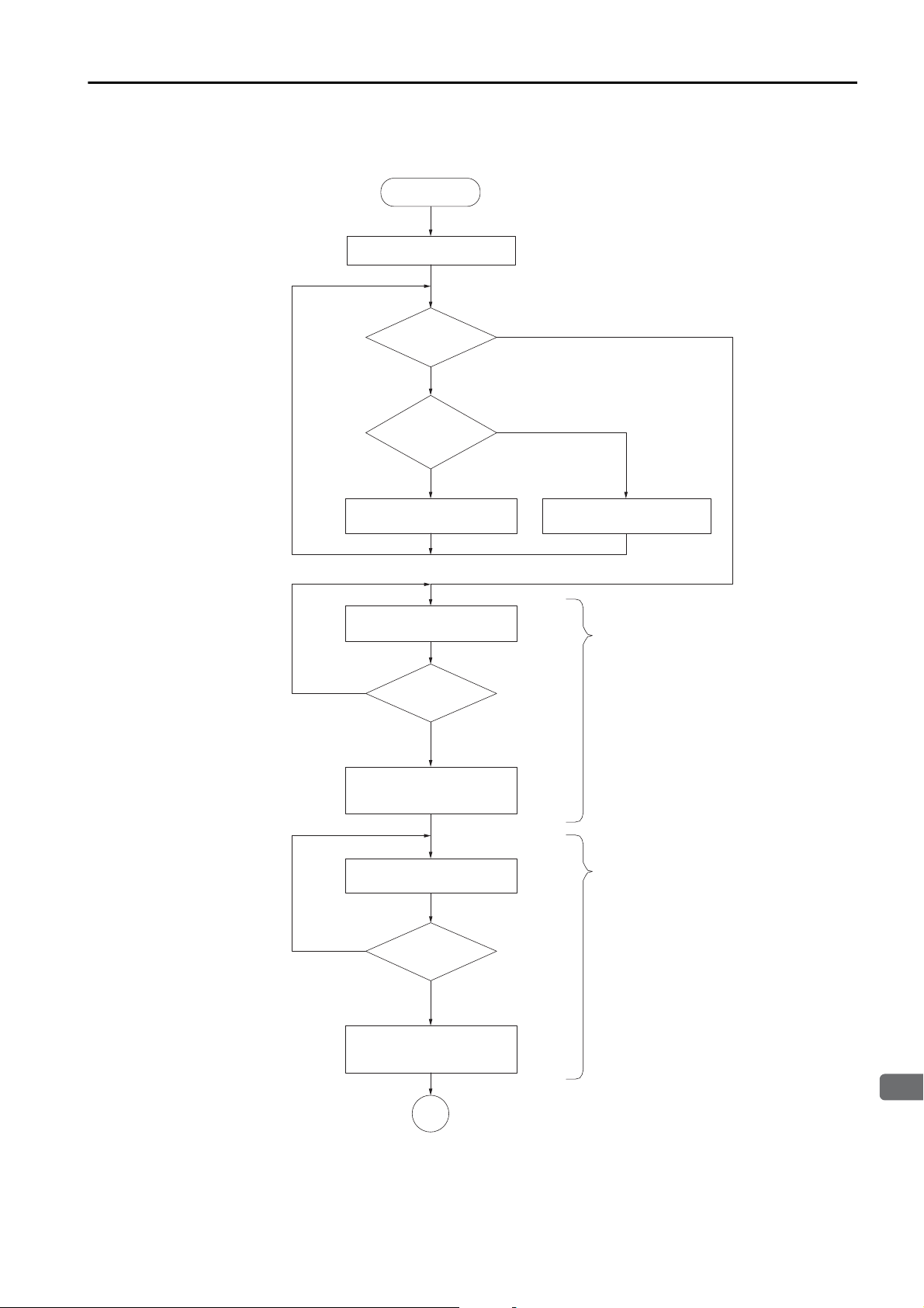
3.6 Setup Procedure
3
Pressure Feedback Control
3.6.7 Gain Adjustment
Gain Adjustment Flowchart
A gain adjustment flowchart for pressure feedback control 1 is provided below.
Start of Adjustment
Set the parameters to
the default settings.
No vibration
Check the
response waveform.
Vibration
Is Pn452
(Pressure Feedback Loop
Proportional Gain 2)
set to 0?
No
Decrease Pn452 (Pressure Feedback
Loop Proportional Gain 2).
Decrease Pn442 (Pressure Feedback
Loop Integral Time) by 0.1 ms.
Check the
response waveform.
Vibration or overshooting
No vibration
Yes
Increase Pn442 (Pressure Feedback
Loop Integral Time).
Adjustment of Pn442
(integral time)
No vibration
Set Pn442 (Pressure Feedback Loop
Integral Time) to the optimum value.
Increase Pn452 (Pressure Feedback
Loop Proportional Gain 2) by 10%.
Check the
response waveform.
Vibration or overshooting
Set Pn452 (Pressure Feedback
Loop Proportional Gain 2)
to the optimum value.
A
Adjustment of Pn452
(proportional gain)
3-21
Page 72

3.6 Setup Procedure
A
End of Adjustment
Overshooting
No overshooting
Did overshooting
decrease?
Yes
Yes
Decrease the value of Pn451 (Pressure Feedback
Loop Differential Filter Multiplier) by 10%.
Vibration
No vibration
No
No
Yes
Set Pn451 (Pressure Feedback
Loop Differential Filter Multiplier)
to the optimum value.
Adjustment of Pn450
(differential time)
Adjustment of Pn451
(differential lter rate)
No
Increase Pn450 (Pressure Feedback
Loop Differential Time) by 0.1 ms.
Was vibration
reduced?
Was vibration
reduced?
Increase the value of Pn451 (Pressure Feedback
Loop Differential Filter Multiplier) by 10%.
Check the
response waveform.
Check the
response waveform.
3.6.7 Gain Adjustment
3-22
Page 73

3.7 Monitoring
3
Pressure Feedback Control
3.7
Monitoring
You can monitor the following signals through analog monitors or through MECHATROLINK-III
communications option monitors.
Analog Monitors
Pn006 or Pn007 Signal Name Output Unit
30h Pressure Feedback Torque Reference Monitor 1 V/100% rated torque
31h Pressure Feedback Detection Monitor 1 V/100% rated torque
32h Pressure Feedback Output Torque Monitor 1 V/100% rated torque
33h Pressure Feedback Loop Deviation Monitor 1 V/100% rated torque
Option Monitors with MECHATROLINK-III Communications
Pn824/Pn825 Signal Name Unit
0050h
0052h
0100h
0101h*
* This can be monitored only when you use the FT41.
Pressure Feedback
Detection Monitor
Control Method
Change Monitor
Speed/Torque (Pressure) Table Operation
Monitor
Other Station Monitor Data
10,000/100% rated torque
0: Position or speed control, 1: Torque control,
3: Pressure feedback
Upper 16 bits: Pressure feedback value [0.01%]
Lower 16 bits: Speed/torque (pressure) table operation
status monitor value
Upper 16 bits: Other station monitor value 2
Lower 16 bits: Other station monitor value 1
Monitoring with SigmaWin+ Waveform Traces
Signal Name Unit
Pressure Feedback Torque Reference Monitor %
Pressure Feedback Detection Monitor %
Pressure Feedback Output Torque Monitor %
Pressure Feedback Loop Deviation Monitor %
Monitoring with SigmaWin+ I/O Tracing
Signal Name Selected Data Name Description
Control Method
Selection Bit 0
Control Method
Selection Bit 1
/A feedback 0
/A feedback 1
Position/speed control: High, Torque control: Low,
Pressure feedback: Low
Position/speed control: High, Torque control: High,
Pressure feedback: Low
3-23
Page 74

Speed/Torque (Pressure) Table Operation
This chapter describes speed/torque (pressure) table operation in detail.
4
4.1
4.2
4.3
4.4
4.5
Introduction . . . . . . . . . . . . . . . . . . . . . . . . . 4-2
Operation Patterns for Speed/Torque (Pressure) Table Operation . . 4-3
Table Parameter Settings for Speed/Torque (Pressure) Table Operation . . 4-4
4.3.1 Setting the Number of Speed Table References
and the Number of Torque (Pressure) References . . 4-4
4.3.2 Settings for Speed Table Operation . . . . . . . . . . 4-5
4.3.3 Setting Condition for Changing from Speed Table
Operation to Torque (Pressure) Table Operation . . 4-7
4.3.4 Settings for Torque (Pressure) Table Operation . . 4-11
Operating Procedure . . . . . . . . . . . . . . . . . 4-13
Monitoring . . . . . . . . . . . . . . . . . . . . . . . . . 4-14
Page 75

4.1 Introduction
4.1
Introduction
You can use speed/torque (pressure) table operation to perform speed control for up to 10
speeds and pressure (torque) control for up to five torques (pressures) according to table
parameters that are set in the SERVOPACK in advance.
To use speed/torque (pressure) table operation, pressure feedback control must be operating
normally. Refer to the following chapter for details on pressure feedback control.
Chapter 3 Pressure Feedback Control
You can perform speed/torque (pressure) table operation in Speed Control Mode. It cannot be
used in Position Control Mode or Torque Control Mode.
Stop the motor before you change from Position Control Mode or Torque Control Mode to
Speed Control Mode.
4-2
Page 76

4.2 Operation Patterns for Speed/Torque (Pressure) Table Operation
4
Speed/Torque (Pressure) Table Operation
Speed table operation
Reference units
Speed
reference
Torque
reference
Speed Table
Switching Position 4
(Pn6C6)
Speed Table
Switching Position 2
(Pn6C2)
Torque (pressure) table operation
%
Speed Table Reference 4
(Pn6B2)
Speed Table Reference 2
(Pn6AE)
Speed Table Reference 1
(Pn6AC)
Speed Table Reference 4
(Pn6B0)
Torque (Pressure)
Reference 3 (Pn6D6)
Torque (Pressure)
Reference 2
Torque (Pressure)
Reference 1 (Pn6D2)
Torque (Pressure)
Reference Time 3 (Pn6E0)
Torque (Pressure)
Reference Time 2 (Pn6DE)
Torque (Pressure)
Reference Time 1 (Pn6DC)
Speed Table
Switching Position 3
(Pn6C4)
Speed Table
Switching Position 1
(Pn6C0)
Condition for changing from
speed table operation to torque
(pressure) table operation
(Pn6A6 × Pn6D2)
4.2
Operation Patterns for Speed/Torque (Pressure) Table Operation
This section provides an example of speed/torque (pressure) table operation. The following
example is for changing from speed table operation (speed table reference 4) to torque (pressure) table operation (speed table reference 1).
4-3
Page 77

4.3 Table Parameter Settings for Speed/Torque (Pressure) Table Operation
4.3.1 Setting the Number of Speed Table References and the Number of Torque (Pressure) References
4.3
4.3.1
Table Parameter Settings for Speed/Torque (Pressure) Table Operation
To perform speed/torque (pressure) table operation, table parameters, such as the speed table
references, speed table switching positions, torque (pressure) references, and torque (pressure)
reference times, must be set in advance.
This section describes the table parameters that must be set.
Setting the Number of Speed Table References and the
Number of Torque (Pressure) References
Set Pn6A4 = n.X (Selection of Number of Speed Table References) to the number of
speed table references to use in speed table operation of speed/torque (pressure) operation.
Set Pn6A4 = n.X (Selection of Number of Torque (Pressure) References) to the number of
torque (pressure) references to use in torque (pressure) table operation of speed/torque (pressure) table operation.
Parameter Meaning When Enabled Classification
n.0
(default setting)
n.1
n.2
n.3
n.4
n.5
n.6
Pn6A4
n.7
n.8
n.9
n.A
n.0
(default setting)
n.1
n.2
Do not perform speed table operation.
Use speed table reference 1 (Pn6AC) for
speed table operation.
Use speed table reference 1 (Pn6AC) and
speed table reference 2 (Pn6AE) for speed
table operation.
Use speed table reference 1 (Pn6AC) through
speed table reference 3 (Pn6B0) for speed
table operation.
Use speed table reference 1 (Pn6AC) through
speed table reference 4 (Pn6B2) for speed
table operation.
Use speed table reference 1 (Pn6AC) through
speed table reference 5 (Pn6B4) for speed
table operation.
Use speed table reference 1 (Pn6AC) through
speed table reference 6 (Pn6B6) for speed
table operation.
Use speed table reference 1 (Pn6AC) through
speed table reference 7 (Pn6B8) for speed
table operation.
Use speed table reference 1 (Pn6AC) through
speed table reference 8 (Pn6BA) for speed
table operation.
Use speed table reference 1 (Pn6AC) through
speed table reference 9 (Pn6BC) for speed
table operation.
Use speed table reference 1 (Pn6AC) through
speed table reference 10 (Pn6BE) for speed
table operation.
Do not perform torque (pressure) table operation.
Use torque (pressure) table reference 1
(Pn6D2) for torque (pressure) table operation.
Use torque (pressure) table reference 1
(Pn6D2) and torque (pressure) table reference
2 (Pn6D4) for torque (pressure) table operation.
Immediately Setup
Continued on next page.
4-4
Page 78

4
Speed/Torque (Pressure) Table Operation
Pn6A4
Speed
Speed
Speed
Speed
Speed
Speed
Speed
Speed
Speed
4.3 Table Parameter Settings for Speed/Torque (Pressure) Table Operation
4.3.2 Settings for Speed Table Operation
Continued from previous page.
Parameter Meaning When Enabled Classification
Use torque (pressure) table reference 1
n.3
n.5
(Pn6D2) through torque (pressure) table reference 3 (Pn6D6) for torque (pressure) table
operation.
Use torque (pressure) table reference 1
(Pn6D2) through torque (pressure) table reference 4 (Pn6D8) for torque (pressure) table
operation.
Use torque (pressure) table reference 1
(Pn6D2) through torque (pressure) table reference 5 (Pn6DA) for torque (pressure) table
operation.
Immediately Setupn.4
4.3.2
Settings for Speed Table Operation
Set the ten speeds for speed table operation in Pn6AC to Pn6BE and the speed table switching positions for the ten speeds for speed table operation in Pn6C0 to Pn6D0.
Pn6AC
Pn6AE
Pn6B0
Pn6B2
Pn6B4
Pn6B6
Pn6B8
Pn6BA
Pn6BC
Speed Table Reference 1
Setting Range Setting Unit Default Setting When Enabled Classification
0 to
2,147,483,647
Speed Table Reference 2
Setting Range Setting Unit Default Setting When Enabled Classification
0 to
2,147,483,647
Speed Table Reference 3
Setting Range Setting Unit Default Setting When Enabled Classification
0 to
2,147,483,647
Speed Table Reference 4
Setting Range Setting Unit Default Setting When Enabled Classification
0 to
2,147,483,647
Speed Table Reference 5
Setting Range Setting Unit Default Setting When Enabled Classification
0 to
2,147,483,647
Speed Table Reference 6
Setting Range Setting Unit Default Setting When Enabled Classification
0 to
2,147,483,647
Speed Table Reference 7
Setting Range Setting Unit Default Setting When Enabled Classification
0 to
2,147,483,647
Speed Table Reference 8
Setting Range Setting Unit Default Setting When Enabled Classification
0 to
2,147,483,647
Speed Table Reference 9
Setting Range Setting Unit Default Setting When Enabled Classification
0 to
2,147,483,647
1 reference unit/s 0 Immediately Setup
1 reference unit/s 0 Immediately Setup
1 reference unit/s 0 Immediately Setup
1 reference unit/s 0 Immediately Setup
1 reference unit/s 0 Immediately Setup
1 reference unit/s 0 Immediately Setup
1 reference unit/s 0 Immediately Setup
1 reference unit/s 0 Immediately Setup
1 reference unit/s 0 Immediately Setup
Continued on next page.
4-5
Page 79

4.3 Table Parameter Settings for Speed/Torque (Pressure) Table Operation
Speed
Speed
Speed
Speed
Speed
Speed
Speed
Speed
Speed
Speed
4.3.2 Settings for Speed Table Operation
Speed Table Reference 10
Pn6BE
Pn6C0
Pn6C2
Pn6C4
Pn6C6
Pn6C8
Pn6CA
Pn6CC
Pn6CE
Pn6D0
Setting Range Setting Unit Default Setting When Enabled Classification
0 to
2,147,483,647
Speed Table Switching Position 1
Setting Range Setting Unit Default Setting When Enabled Classification
0 to
2,147,483,647
Speed Table Switching Position 2
Setting Range Setting Unit Default Setting When Enabled Classification
0 to
2,147,483,647
Speed Table Switching Position 3
Setting Range Setting Unit Default Setting When Enabled Classification
0 to
2,147,483,647
Speed Table Switching Position 4
Setting Range Setting Unit Default Setting When Enabled Classification
0 to
2,147,483,647
Speed Table Switching Position 5
Setting Range Setting Unit Default Setting When Enabled Classification
0 to
2,147,483,647
Speed Table Switching Position 6
Setting Range Setting Unit Default Setting When Enabled Classification
0 to
2,147,483,647
Speed Table Switching Position 7
Setting Range Setting Unit Default Setting When Enabled Classification
0 to
2,147,483,647
Speed Table Switching Position 8
Setting Range Setting Unit Default Setting When Enabled Classification
0 to
2,147,483,647
Speed Table Switching Position 9
Setting Range Setting Unit Default Setting When Enabled Classification
0 to
2,147,483,647
1 reference unit/s 0 Immediately Setup
1 reference unit/s 0 Immediately Setup
1 reference unit/s 0 Immediately Setup
1 reference unit/s 0 Immediately Setup
1 reference unit/s 0 Immediately Setup
1 reference unit/s 0 Immediately Setup
1 reference unit/s 0 Immediately Setup
1 reference unit/s 0 Immediately Setup
1 reference unit/s 0 Immediately Setup
1 reference unit/s 0 Immediately Setup
Each of the speed table switching positions 1 to 9 corresponds to one pair of speed table references 1 to 10. Refer to the following diagram for the speed table references and speed table
switching positions, and set the parameters in ascending order of parameter numbers.
Continued from previous page.
4-6
Page 80

4.3 Table Parameter Settings for Speed/Torque (Pressure) Table Operation
4
Speed/Torque (Pressure) Table Operation
Speed Table Reference 10 (Pn6BE)
Speed Table Reference 9 (Pn6BC)
Speed Table Reference 8 (Pn6BA)
Speed Table Reference 7 (Pn6B8)
Speed Table Reference 6 (Pn6B6)
Speed Table Reference 5 (Pn6B4)
Speed Table Reference 4 (Pn6B2)
Speed Table Reference 3 (Pn6B0)
Speed Table Reference 2 (Pn6AE)
Speed Table Reference 1 (Pn6AC)
Speed reference
Speed Table
Switching Position 1
(Pn6C0)
Speed Table
Switching Position 2
(Pn6C2)
Speed Table
Switching Position 3
(Pn6C4)
Speed Table
Switching Position 4
(Pn6C6)
Speed Table
Switching Position 5
(Pn6C8)
Speed Table
Switching Position 6
(Pn6CA)
Speed Table
Switching Position 7
(Pn6CC)
Speed Table
Switching Position 8
(Pn6CE)
Speed Table
Switching Position 9
(Pn6D0)
Position
4.3.3 Setting Condition for Changing from Speed Table Operation to Torque (Pressure) Table Operation
4.3.3
Setting Condition for Changing from Speed Table Operation to Torque (Pressure) Table Operation
You can use Pn6A4 = n.
Pn6A4 = n.X
lowing three conditions for switching from speed table operation to torque (pressure) table
operation.
• Pn6A4 = n.0
Speed table operation changes to torque (pressure) table operation when the pressure feedback detection value exceeds Pn6A7 × Pn6D2 and the motor position exceeds Pn6A8.
• Pn6A4 = n.0
Speed table operation changes to torque (pressure) table operation when the pressure feedback detection value exceeds Pn6A7 × Pn6D2 or the motor position exceeds Pn6A8.
• Pn6A4 = n.1
During speed table operation, if the pressure feedback detection value falls to the setting for
Pn44C (Pressure Feedback Enable Level) or less, torque references are restricted to the setting of Pn6A5 (Torque (Pressure) Reference during Speed Table Operation) or less. The pressure reference in Pn6A5 functions as the maximum limit when the pressure feedback
detection value exceeds the value of Pn44C.
Speed table operation changes to torque (pressure) table operation when the motor position
exceeds the table operation switching position (Pn6A8). After operation changes to pressure
table operation, the pressure feedback control follows the setting in Pn44C.
X (Table Operation Control Switching Condition Selection) and
(Table Operation Control Method Switching Selection) to select from the fol-
0
1
4-7
Page 81

4.3 Table Parameter Settings for Speed/Torque (Pressure) Table Operation
Speed
Speed
Speed
Speed
4.3.3 Setting Condition for Changing from Speed Table Operation to Torque (Pressure) Table Operation
Parameter Meaning When Enabled Classification
Switch from speed table operation to torque
n.
0
(Default Setting)
(pressure) table operation when the pressure
feedback detection value exceeds Pn6A7 ×
Pn6D2 and the motor position exceeds
Pn6A8.
Pn6A4
n.
1
Switch from speed table operation to torque
(pressure) table operation when the pressure
feedback detection value exceeds Pn6A7 ×
Immediately Setup
Pn6D2 or the motor position exceeds Pn6A8.
n.0
(Default Setting)
n.1 Disable Pn6A4 = n.
Disable Pn6A5 and enable Pn6A4 = n.
X and enable Pn6A5.
X.
Pn6A5
Torque (Pressure) Reference during Speed Table Operation
Setting Range Setting Unit Default Setting When Enabled Classification
0 to
1,073,741,824
1% 0 Immediately Setup
Pressure Control Switching Pressure Percentage
Pn6A7 Setting Range Setting Unit Default Setting When Enabled Classification
0 to 10,000 0.01% 0 Immediately Setup
Pn6D2
Torque (Pressure) Reference 1
Setting Range Setting Unit Default Setting When Enabled Classification
-1,073,741,824 to
1,073,741,824
1% 0 Immediately Setup
Table Operation Switching Position
Pn6A8 Setting Range Setting Unit Default Setting When Enabled Classification
0 to
2,147,483,647
1 reference unit 0 Immediately Setup
4-8
Page 82

4.3 Table Parameter Settings for Speed/Torque (Pressure) Table Operation
4
Speed/Torque (Pressure) Table Operation
Pn6D6
Pn6A8
Pn6C4Pn6C0
Pn6B2
Pn6AE
Pn6B0
Pn6AC
Pn6A7 × Pn6D2
Pn44C
Pn6C2
Pn6D4
Pn6D2
Pn6DC
Pn6DE
Pn6E0
Pressure feedback
Feedback
speed
Speed reference
Tor q ue ( pr e ssure) table operation
Speed table operation
Speed Tor q ue ( pre ssure)
Pn6D6
Pn6B2
Pn6AE
Pn6B0
Pn6AC
Pn6A7 × Pn6D2
Pn44C
Pn6C4Pn6C0
Pn6C2
Pn6D4
Pn6D2
Pn6DC
Pn6DE
Pn6E0
Pressure feedback
Speed reference
Pn6A8
Tor q ue ( pr e ssure) table operation
Speed table operation
Speed
Feedback
speed
Tor q ue ( pre ssure)
4.3.3 Setting Condition for Changing from Speed Table Operation to Torque (Pressure) Table Operation
Torque (Pressure) Table Operation Example for Pn6A4 = n.00
Speed table operation changes to torque (pressure) table operation when the pressure feedback detection value exceeds Pn6A7 × Pn6D2 and the motor position exceeds Pn6A8.
Torque (Pressure) Table Operation Example for Pn6A4 = n.01
Speed table operation changes to torque (pressure) table operation when the pressure feedback detection value exceeds Pn6A7 × Pn6D2 or the motor position exceeds Pn6A8.
In the following example, speed table operation is changed to torque (pressure) table operation
when the motor position exceeds Pn6A8.
4-9
Page 83

4.3 Table Parameter Settings for Speed/Torque (Pressure) Table Operation
Pn6D6
Pn6B2
Pn6AE
Pn6A5
Pn6B0
Pn6AC
Pn44C
Pn6C4Pn6C0
Pn6C2
Pn6D4
Pn6D2
Pn6DC
Pn6DE
Pn6E0
Speed reference
Pn6A8
Tor que ( pr essure) table operation
Speed table operation
Pressure feedback
Speed
Feedback
speed
Tor q ue ( pre ssure)
Pn6D6
Pn6B2
Pn6AE
Pn6A5
Pn6B0
Pn6AC
Pn44C
Pn44A
Pn6C4Pn6C0
Pn6C2
Pn6D4
Pn6D2
Pn6DC
Pn6DE
Pn6E0
Speed reference
Pn6A8
Tor q ue ( pre ssure) table operation
Speed table operation
Pressure feedback
Speed
Feedback
speed
Tor q ue ( pre ssure)
Even if the pressure feedback detection value exceeds the
setting of Pn6A5, speed table operation is continued.
4.3.3 Setting Condition for Changing from Speed Table Operation to Torque (Pressure) Table Operation
Torque (Pressure) Table Operation Example 1 for Pn6A4 = n.1
During speed table operation, if the pressure feedback detection value falls to the setting for
Pn44C (Pressure Feedback Enable Level) or less, torque references are restricted to the setting
of Pn6A5 (Torque (Pressure) Reference during Speed Table Operation) or less. The pressure
reference in Pn6A5 functions as the maximum limit when the pressure feedback detection
value exceeds the value of Pn44C.
Speed table operation changes to torque (pressure) table operation when the motor position
exceeds the table operation switching position (Pn6A8). After operation changes to pressure
table operation, the pressure feedback control follows the setting in Pn44C.
In the following example, speed table operation is changed to torque (pressure) table operation
when the motor position exceeds Pn6A8 even if the pressure feedback detection value does
not exceed Pn44C.
4-10
Torque (Pressure) Table Operation Example 2 for Pn6A4 = n.1
During speed table operation, if the pressure feedback detection value falls to the setting for
Pn44C (Pressure Feedback Enable Level) or less, torque references are restricted to the setting
of Pn6A5 (Torque (Pressure) Reference during Speed Table Operation) or less. The pressure
reference in Pn6A5 functions as the maximum limit when the pressure feedback detection
value exceeds the value of Pn44C.
Speed table operation changes to torque (pressure) table operation when the motor position
exceeds the table operation switching position (Pn6A8). After operation changes to pressure
table operation, the pressure feedback control follows the setting in Pn44C.
In the following example, the pressure feedback detection value exceeds Pn44C, so the motor
operates at the pressure reference in Pn6A5. When the motor position exceeds Pn6A8, speed
table operation changes to torque (pressure) table operation.
Page 84

4.3 Table Parameter Settings for Speed/Torque (Pressure) Table Operation
4
Speed/Torque (Pressure) Table Operation
Speed
Speed
Speed
Speed
Speed
Speed
Speed
Speed
Speed
Speed
4.3.4 Settings for Torque (Pressure) Table Operation
4.3.4
Settings for Torque (Pressure) Table Operation
Set the five torque (pressure) references in Pn6D2 to Pn6DA and the torque (pressure) reference times at which to change between the five torque (pressure) references in Pn6DC to
Pn6E2.
You can set the the speed limit for torque (pressure) table operation in Pn6AA (Speed Limit for
Torque (Pressure) Table Operation).
The speed will not exceed the value of Pn6AA (Speed Limit for Torque (Pressure) Table Operation).
Pn6D2
Pn6D4
Pn6D6
Pn6D8
Pn6DA
Pn6DC
Pn6DE
Pn6E0
Pn6E2
Pn6AA
Torque (Pressure) Reference 1
Setting Range Setting Unit Default Setting When Enabled Classification
-1,073,741,824 to
1,073,741,824
Torque (Pressure) Reference 2
Setting Range Setting Unit Default Setting When Enabled Classification
-1,073,741,824 to
1,073,741,824
Torque (Pressure) Reference 3
Setting Range Setting Unit Default Setting When Enabled Classification
-1,073,741,824 to
1,073,741,824
Torque (Pressure) Reference 4
Setting Range Setting Unit Default Setting When Enabled Classification
-1,073,741,824 to
1,073,741,824
Torque (Pressure) Reference 5
Setting Range Setting Unit Default Setting When Enabled Classification
-1,073,741,824 to
1,073,741,824
Torque (Pressure) Reference Time 1
Setting Range Setting Unit Default Setting When Enabled Classification
0 to 180,000 0.01 s 0 Immediately Setup
Torque (Pressure) Reference Time 2
Setting Range Setting Unit Default Setting When Enabled Classification
0 to 180,000 0.01 s 0 Immediately Setup
Torque (Pressure) Reference Time 3
Setting Range Setting Unit Default Setting When Enabled Classification
0 to 180,000 0.01 s 0 Immediately Setup
Torque (Pressure) Reference Time 4
Setting Range Setting Unit Default Setting When Enabled Classification
0 to 180,000 0.01 s 0 Immediately Setup
Speed Limit for Torque (Pressure) Table Operation
Setting Range Setting Unit Default Setting When Enabled Classification
0 to
2,147,483,647
1% 0 Immediately Setup
1% 0 Immediately Setup
1% 0 Immediately Setup
1% 0 Immediately Setup
1% 0 Immediately Setup
1 reference unit/s 0 Immediately Setup
4-11
Page 85

4.3 Table Parameter Settings for Speed/Torque (Pressure) Table Operation
Torque (Pressure) Reference 5 (Pn6DA)
Torque (Pressure) Reference 4 (Pn6D8)
Torque (Pressure) Reference 3 (Pn6D6)
Torque (Pressure) Reference 2 (Pn6D4)
Torque (Pressure) Reference 1 (Pn6D2)
Torque reference
Time
Torque (Pressure)
Reference Time 1 (Pn6DC)
Torque (Pressure)
Reference Time 2 (Pn6DE)
Torqu e ( P r e ssure)
Reference Time 3 (Pn6E0)
Torque (Pressure)
Reference Time 4 (Pn6E2)
4.3.4 Settings for Torque (Pressure) Table Operation
Each of the torque (pressure) reference times 1 to 4 corresponds to one pair of torque (pressure) references 1 to 5. Refer to the following diagram for the torque (pressure) references and
torque (pressure) reference times, and set the parameters in ascending order of parameter
numbers.
4-12
Page 86

4.4 Operating Procedure
4
Speed/Torque (Pressure) Table Operation
Important
4.4
Operating Procedure
Speed/torque (pressure) table operation is controlled with the VELCTRL speed control command in MECHATROLINK-III communications.
This section provides the operating procedure for speed/torque (pressure) table operation.
1.
Set Pn440 to n.1 (Enable pressure feedback control).
2.
Send the SV_ON (Servo ON) command.
3.
Other station monitoring is set and checked only when you use the FT41.
Refer to the following section for details.
Setting and Checking Other Station Monitoring
3.6.3
4.
Set bits 28 and 29 in the SVCMD_IO area of the VELCTRL command to 1.
• SVCMD_IO (Output) Area
Bit 7 Bit 6 Bit 5 Bit 4 Bit 3 Bit 2 Bit 1 Bit 0
N_CL P_CL P_PPI V_PPI Reserved (0).
Bit 15 Bit 14 Bit 13 Bit 12 Bit 11 Bit 10 Bit 9 Bit 8
Reserved (0). G-SEL
Bit 23 Bit 22 Bit 21 Bit 20 Bit 19 Bit 18 Bit 17 Bit 16
Reserved. SO3 SO2 SO1 BANK_SEL
on page 3-10
Bit 31 Bit 30 Bit 29 Bit 28 Bit 27 Bit 26 Bit 25 Bit 24
Speed/
Speed/
To rq ue
Reserved (0).
• Output Signal Bit Descriptions
Bit Command Valu e Setting
Speed/Torque (Pres-
sure) Table Operation
28
29
Do not use the CMD_PAUSE (Pause) or CMD_CANCEL (Cancel) commands during speed/torque
(pressure) table operation. The send timing will affect behavior and may prevent normal control
operations.
Preparations Start Bit
If bit 28 is ON, the VELCTRL command is interpreted as a speed/torque (pressure)
table operation command.
Speed/Torque (Pres-
sure) Table Operation
If bit 28 is OFF, only VELCTRL commands are acknowledged.
(Pressure)
Ta bl e
Operation
Reference
Reference
Torq ue
(Pressure)
Tab le
Operation
Prepara-
tions Start
Bit
0Do not start.
Start reception of speed/torque
1
(pressure) table operation commands.
0 No command, or cancel operation.
Start speed/torque (pressure) table
1
operation.
Reserved (0).
When
Enabled
Level
Level
4-13
Page 87

4.5 Monitoring
4.5
Monitoring
You can monitor the following signals through analog monitors or through MECHATROLINK-III
communications option monitors.
Analog Monitors
Pn006 or Pn007 Signal Name Output Unit
30h Pressure Feedback Torque Reference Monitor 1 V/100% rated torque
31h Pressure Feedback Detection Monitor 1 V/100% rated torque
32h Pressure Feedback Output Torque Monitor 1 V/100% rated torque
33h Pressure Feedback Loop Deviation Monitor 1 V/100% rated torque
Option Monitors with MECHATROLINK-III Communications
Pn824/Pn825 Signal Name Unit
0050h
0052h
0100h
0101h*
* This can be monitored only when you use the FT41.
Pressure Feedback
Detection Monitor
Control Method
Change Monitor
Speed/Torque (Pressure) Table Operation
Monitor
Other Station Monitor Data
10,000/100% rated torque
0: Position or speed control, 1: Torque control, 3: Pressure
feedback
- (channel 1/channel 2)
-
Monitoring with SigmaWin+ Waveform Traces
Signal Name Unit
Pressure Feedback Torque Reference Monitor %
Pressure Feedback Detection Monitor %
Pressure Feedback Output Torque Monitor %
Pressure Feedback Loop Deviation Monitor %
Monitoring with SigmaWin+ I/O Tracing
Signal Name Selected Data Name Description
Control Method
Selection Bit 0
Control Method
Selection Bit 1
/A feedback 0
/A feedback 1
Position/speed control: High, Torque control: Low,
Pressure feedback: Low
Position/speed control: High, Torque control: High,
Pressure feedback: Low
4-14
Page 88

4.5 Monitoring
4
Speed/Torque (Pressure) Table Operation
Speed/Torque (Pressure) Table Operation Monitor
• Monitor Area
You must allocate the pressure sensor values to use in the speed/torque (pressure) operation
sequence and pressure control in the pressure monitor.
Bit 7 Bit 6 Bit 5 Bit 4 Bit 3 Bit 2 Bit 1 Bit 0
LCIO_RDY*
Bit 15 Bit 14 Bit 13 Bit 12 Bit 11 Bit 10 Bit 9 Bit 8
Bit 23 Bit 22 Bit 21 Bit 20 Bit 19 Bit 18 Bit 17 Bit 16
Bit 31 Bit 30 Bit 29 Bit 28 Bit 27 Bit 26 Bit 25 Bit 24
* Only for the FT41.
Reserved (0).
Reserved (0). Current Sequence Number
Pressure monitor (lower 8 bits)
Pressure monitor (upper 8 bits)
CANCEL
Pressure
Feedback
Status
• Monitor Details
Bit Name Value Setting
0 Not ready for operation
0 or 1
2
3
8 to 11
16 to 31
Speed/Torque (Pres-
sure) Table Operating
Status
The status is 0 after the power supply is turned ON.
The status will change to 1 when preparations for speed/torque (pressure) table
operation have been completed.
Pressure Feedback
Status
The status will be 1 when pressure feedback control is enable.
CANCEL
The status will change to 1 when a command to cancel speed/torque (pressure) table
operation is received. When operation is canceled, the motor is stopped with a speed
reference of 0.
Current Sequence
Number
If speed table reference 5 is being used for speed table operation, these bits will contain 5. If torque (pressure) reference 3 is being used for torque (pressure) table operation, these bits will contain 3. Use the Speed/Torque (Pressure) Table Operating
Status to determine whether speed table operation or torque (pressure) table operation is being performed.
Pressure Monitor 0 to 15 Pressure Feedback Detection Monitor [0.01%]
The pressure feedback detection value is stored here.
1Ready for operation
2 Speed table operation is in progress.
3 Torque (pressure) table operation is in progress.
0 Torque/force control
1 Pressure feedback control
0 Not canceled.
Speed/torque (pressure) table operation monitor
1
canceled.
0Default
The number of the speed table reference or torque
1 to 10
(pressure) reference that is currently being executed.
Speed/Torque (Pres-
sure) Table Operating
Status
4-15
Page 89

Maintenance
This chapter provides information on the meaning of,
causes of, and corrections for alarms and warnings.
5
5.1
5.2
FT40 Specification . . . . . . . . . . . . . . . . . . . 5-2
5.1.1 Alarm Displays . . . . . . . . . . . . . . . . . . . . . . . . . . 5-2
5.1.2 List of Alarms . . . . . . . . . . . . . . . . . . . . . . . . . . . 5-2
5.1.3 Troubleshooting Alarms . . . . . . . . . . . . . . . . . . . . 5-8
5.1.4 Warning Displays . . . . . . . . . . . . . . . . . . . . . . . 5-39
5.1.5 List of Warnings . . . . . . . . . . . . . . . . . . . . . . . . 5-39
5.1.6 Troubleshooting Warnings . . . . . . . . . . . . . . . . . 5-42
5.1.7 Troubleshooting Based on the Operation
and Conditions of the Servomotor . . . . . . . . . . 5-49
FT41 Specification . . . . . . . . . . . . . . . . . . 5-58
5.2.1 Alarm Displays . . . . . . . . . . . . . . . . . . . . . . . . . 5-58
5.2.2 List of Alarms . . . . . . . . . . . . . . . . . . . . . . . . . . 5-58
5.2.3 Troubleshooting Alarms . . . . . . . . . . . . . . . . . . . 5-64
5.2.4 Warning Displays . . . . . . . . . . . . . . . . . . . . . . . 5-95
5.2.5 List of Warnings . . . . . . . . . . . . . . . . . . . . . . . . 5-95
5.2.6 Troubleshooting Warnings . . . . . . . . . . . . . . . . . 5-98
5.2.7 Troubleshooting Based on the Operation
and Conditions of the Servomotor . . . . . . . . . 5-105
Page 90

5.1 FT40 Specification
5.1.1 Alarm Displays
5.1
5.1.1
5.1.2
FT40 Specification
Alarm Displays
If an error occurs in the SERVOPACK, an alarm number will be displayed on the panel display.
If there is an alarm, the display will change in the following order.
Example: Alarm A.E60
Status
Indications
List of Alarms
The list of alarms gives the alarm name, alarm meaning, alarm stopping method, and alarm
reset possibility in order of the alarm numbers.
Servomotor Stopping Method for Alarms
Refer to the following manual for information on the stopping method for alarms.
Σ-7-Series Σ-7S SERVOPACK with MECHATROLINK-III Communications References Product Manual
(Manual No.: SIEP S800001 28)
Not lit. Not lit. Not lit. Not lit. Not lit.
Alarm Reset Possibility
Yes: You can use an alarm reset to clear the alarm. However, this assumes that the cause of
the alarm has been removed.
No: You cannot clear the alarm.
List of Alarms
Alarm
Number
A.020
A.021 Parameter Format Error
A.022 System Checksum Error
A.024 System Alarm
A.025 System Alarm
A.030
A.040 Parameter Setting Error
A.041
Alarm Name Alarm Meaning
Parameter Checksum
Error
Main Circuit Detector
Error
Encoder Output Pulse
Setting Error
There is an error in the parameter data in the
SERVOPACK.
There is an error in the parameter data format in
the SERVOPACK.
There is an error in the parameter data in the
SERVOPACK.
An internal program error occurred in the SERVOPACK.
An internal program error occurred in the SERVOPACK.
There is an error in the detection data for the
main circuit.
A parameter setting is outside of the setting
range.
The setting of Pn212 (Number of Encoder Output
Pulses) or Pn281 (Encoder Output Resolution) is
outside of the setting range or does not satisfy
the setting conditions.
Continued on next page.
Servo-
motor
Stop-
ping
Method
Gr.1 No
Gr.1 No
Gr.1 No
Gr.1 No
Gr.1 No
Gr.1 Yes
Gr.1 No
Gr.1 No
Alarm
Reset
Possi-
ble?
5-2
Page 91

5.1 FT40 Specification
5
Maintenance
5.1.2 List of Alarms
Continued from previous page.
Servo-
Alarm
Number
A.042
A.044
A.04A Parameter Setting Error 2
A.050 Combination Error
A.051
A.070
A.080
A.0b0
A.100 Overcurrent Detected
A.101
A.300 Regeneration Error There is an error related to regeneration. Gr.1 Yes
A.320 Regenerative Overload A regenerative overload occurred. Gr.2 Yes
A.330
A.400 Overvoltage The main circuit DC voltage is too high. Gr.1 Yes
A.410 Undervoltage The main circuit DC voltage is too low. Gr.2 Yes
A.510 Overspeed The motor exceeded the maximum speed. Gr.1 Yes
A.511
A.520 Vibration Alarm
A.521 Autotuning Alarm
A.550
A.710 Instantaneous Overload
A.720 Continuous Overload
A.730
A.731
A.740
Alarm Name Alarm Meaning
Parameter Combination
Error
Semi-Closed/Fully-Closed
Loop Control Parameter
Setting Error
Unsupported Device
Alarm
Motor Type Change
Detected
Linear Encoder Pitch
Setting Error
Invalid Servo ON Command Alarm
Motor Overcurrent
Detected
Main Circuit Power Supply
Wiring Error
Encoder Output Pulse
Overspeed
Maximum Speed Setting
Error
Dynamic Brake Overload
Inrush Current Limiting
Resistor Overload
The combination of some parameters exceeds
the setting range.
The settings of the Option Module and Pn002 =
n.X (External Encoder Usage) do not
match.
There is an error in the bank members or bank
data settings.
The capacities of the SERVOPACK and Servomotor do not match.
An unsupported device was connected. Gr.1 No
The connected motor is a different type of motor
from the previously connected motor.
The setting of Pn282 (Linear Encoder Scale Pitch)
has not been changed from the default setting.
The SV_ON (Servo ON) command was sent from
the host controller after a utility function that turns
ON the Servomotor was executed.
An overcurrent flowed through the power transistor or the heat sink overheated.
The current to the motor exceeded the allowable
current.
• The AC power supply input setting or DC power
supply input setting is not correct.
• The power supply wiring is not correct.
• The pulse output speed for the setting of Pn212
(Number of Encoder Output Pulses) was
exceeded. (This applies to Rotary Servomotors.)
• The motor speed upper limit for the setting of
Pn281 (Encoder Output Resolution) was
exceeded. (This applies to Linear Servomotors.)
Abnormal oscillation was detected in the motor
speed.
Vibration was detected during autotuning for the
tuning-less function.
The setting of Pn385 (Maximum Motor Speed) is
greater than the maximum motor speed.
The Servomotor was operating for several seconds to several tens of seconds under a torque
that largely exceeded the rating.
The Servomotor was operating continuously
under a torque that exceeded the rating.
When the dynamic brake was applied, the rotational or linear kinetic energy exceeded the
capacity of the dynamic brake resistor.
The main circuit power supply was frequently
turned ON and OFF.
motor
Stop-
ping
Method
Gr.1 No
Gr.1 No
Gr.1 No
Gr.1 Yes
Gr.1 No
Gr.1 No
Gr.1 Yes
Gr.1 No
Gr.1 No
Gr.1 Yes
Gr.1 Yes
Gr.1 Yes
Gr.1 Yes
Gr.1 Yes
Gr.2 Yes
Gr.1 Yes
Gr.1 Yes
Gr.1 Yes
Continued on next page.
Alarm
Reset
Possi-
ble?
5-3
Page 92

5.1 FT40 Specification
5.1.2 List of Alarms
Alarm
Number
A.7A1
A.7A2
A.7A3
A.7Ab
A.810 Encoder Backup Alarm
A.820 Encoder Checksum Alarm
A.830 Encoder Battery Alarm
A.840 Encoder Data Alarm There is an internal data error in the encoder. Gr.1 No
A.850 Encoder Overspeed
A.860 Encoder Overheated The internal temperature of encoder is too high. Gr.1 No
A.861 Motor Overheated The internal temperature of motor is too high. Gr.1 No
A.890
A.891
A.8A0 External Encoder Error An error occurred in the external encoder. Gr.1 Yes
A.8A1
A.8A2
A.8A3
A.8A5
A.8A6
A.b33 Current Detection Error 3 An error occurred in the current detection circuit. Gr.1 No
A.b6A
A.b6b
A.bF0 System Alarm 0
A.bF1 System Alarm 1
A.bF2 System Alarm 2
A.bF3 System Alarm 3
A.bF4 System Alarm 4
A.bF5 System Alarm 5
Alarm Name Alarm Meaning
Internal Temperature Error
1 (Control Board Temperature Error)
Internal Temperature Error
2 (Power Board Temperature Error)
Internal Temperature Sensor Error
SERVOPACK Built-in Fan
Stopped
Encoder Scale Error
Encoder Module Error
External Encoder Module
Error
External Incremental
Encoder Sensor Error
External Absolute Encoder
Position Error
External Encoder Overspeed
External Encoder Overheated
MECHATROLINK Communications ASIC Error 1
MECHATROLINK Communications ASIC Error 2
The surrounding temperature of the control PCB
is abnormal.
The surrounding temperature of the power PCB
is abnormal.
An error occurred in the temperature sensor circuit.
The fan inside the SERVOPACK stopped. Gr.1 Yes
The power supplies to the encoder all failed and
the position data was lost.
There is an error in the checksum results for
encoder memory.
The battery voltage was lower than the specified
level after the control power supply was turned
ON.
The encoder was operating at high speed when
the power was turned ON.
A failure occurred in the linear encoder. Gr.1 No
An error occurred in the linear encoder. Gr.1 No
An error occurred in the Serial Converter Unit. Gr.1 Yes
An error occurred in the external encoder. Gr.1 Yes
An error occurred in the position data of the
external encoder.
An overspeed error occurred in the external
encoder.
An overheating error occurred in the external
encoder.
ASIC error 1 occurred in MECHATROLINK communications.
ASIC error 2 occurred in MECHATROLINK communications.
Internal program error 0 occurred in the SERVOPACK .
Internal program error 1 occurred in the SERVOPACK .
Internal program error 2 occurred in the SERVOPACK .
Internal program error 3 occurred in the SERVOPACK .
Internal program error 4 occurred in the SERVOPACK .
Internal program error 5 occurred in the SERVOPACK .
Continued from previous page.
Servo-
motor
Stop-
ping
Method
Gr.2 Yes
Gr.2 Yes
Gr.2 No
Gr.1 No
Gr.1 No
Gr.1 Yes
Gr.1 No
Gr.1 Yes
Gr.1 Yes
Gr.1 Yes
Gr.1 No
Gr.2 No
Gr.1 No
Gr.1 No
Gr.1 No
Gr.1 No
Gr.1 No
Gr.1 No
Continued on next page.
Alarm
Reset
Possi-
ble?
5-4
Page 93

5.1 FT40 Specification
5
Maintenance
5.1.2 List of Alarms
Continued from previous page.
Servo-
Alarm
Number
A.bF6 System Alarm 6
A.bF7 System Alarm 7
A.bF8 System Alarm 8
A.C10 Servomotor Out of Control The Servomotor ran out of control. Gr.1 Yes
A.C20 Phase Detection Error The detection of the phase is not correct. Gr.1 No
A.C21 Polarity Sensor Error An error occurred in the polarity sensor. Gr.1 No
A.C22
A.C50
A.C51
A.C52
A.C53
A.C54
A.C80
A.C90
A.C91
A.C92
A.CA0 Encoder Parameter Error The parameters in the encoder are corrupted. Gr.1 No
A.Cb0 Encoder Echoback Error
A.CC0
A.CF1
A.CF2
A.d00
A.d01
Alarm Name Alarm Meaning
Internal program error 6 occurred in the SERVOPAC K.
Internal program error 7 occurred in the SERVOPAC K.
Internal program error 8 occurred in the SERVOPAC K.
Phase Information
Disagreement
Polarity Detection Failure
Overtravel Detected during
Polarity Detection
Polarity Detection Not
Completed
Out of Range of Motion for
Polarity Detection
Polarity Detection Failure 2
Encoder Clear Error or
Multiturn Limit Setting
Error
Encoder Communications
Error
Encoder Communications
Position Data Acceleration
Rate Error
Encoder Communications
Timer Error
Multiturn Limit Disagreement
Reception Failed Error in
Feedback Option Module
Communications
Timer Stopped Error in
Feedback Option Module
Communications
Position Deviation Overflow
Position Deviation Overflow Alarm at Servo ON
The phase information does not match. Gr.1 No
The polarity detection failed. Gr.1 No
The overtravel signal was detected during polarity
detection.
The servo was turned ON before the polarity was
detected.
The travel distance exceeded the setting of
Pn48E (Polarity Detection Range).
The polarity detection failed. Gr.1 No
The multiturn data for the absolute encoder was
not correctly cleared or set.
Communications between the encoder and SERVOPACK is not possible.
An error occurred in calculating the position data
of the encoder.
An error occurred in the communications timer
between the encoder and SERVOPACK.
The contents of communications with the
encoder are incorrect.
Different multiturn limits have been set in the
encoder and the SERVOPACK.
Receiving data from the Feedback Option Module failed.
An error occurred in the timer for communications with the Feedback Option Module.
The setting of Pn520 (Position Deviation Overflow
Alarm Level) was exceeded by the position deviation while the servo was ON.
The servo was turned ON after the position deviation exceeded the setting of Pn526 (Position
Deviation Overflow Alarm Level at Servo ON)
while the servo was OFF.
motor
Stop-
ping
Method
Gr.1 No
Gr.1 No
Gr.1 No
Gr.1 Yes
Gr.1 Yes
Gr.1 No
Gr.1 No
Gr.1 No
Gr.1 No
Gr.1 No
Gr.1 No
Gr.1 No
Gr.1 No
Gr.1 No
Gr.1 Yes
Gr.1 Yes
Continued on next page.
Alarm
Reset
Possi-
ble?
5-5
Page 94

5.1 FT40 Specification
5.1.2 List of Alarms
Alarm
Number
A.d02
A.d0A
A.d10
A.d30 Position Data Overflow
A.E02
A.E40
A.E41
A.E42
A.E50*
A.E51
A.E60*
A.E61
A.E63
A.E71
A.E72
A.E74
A.Eb1
A.EC8 Gate Drive Error 1 An error occurred in the gate drive circuit. Gr.1 No
A.EC9 Gate Drive Error 2 An error occurred in the gate drive circuit. Gr.1 No
A.Ed1
Alarm Name Alarm Meaning
If position deviation remains in the deviation
Position Deviation Overflow Alarm for Speed Limit
at Servo ON
Pressure Feedback Loop
Deviation Overflow
Motor-Load Position Deviation Overflow
MECHATROLINK Internal
Synchronization Error 1
MECHATROLINK Transmission Cycle Setting
Error
MECHATROLINK Communications Data Size Setting Error
MECHATROLINK Station
Address Setting Error
MECHATROLINK Synchronization Error
MECHATROLINK Synchronization Failed
Reception Error in
MECHATROLINK Communications
Synchronization Interval
Error in MECHATROLINK
Transmission Cycle
MECHATROLINK Synchronization Frame Not
Received
Safety Option Module
Detection Failure
Feedback Option Module
Detection Failure
Unsupported Safety
Option Module
Safety Function Signal
Input Timing Error
Command Execution Timeout
counter, the setting of Pn529 or Pn584 (Speed
Limit Level at Servo ON) limits the speed when
the servo is turned ON. This alarm occurs if a
position reference is input and the setting of
Pn520 (Position Deviation Overflow Alarm Level)
is exceeded before the limit is cleared.
The difference between the pressure feedback
reference and the feedback detection value
exceeded Pn447 (Pressure Feedback Loop Deviation Overflow Level).
There was too much position deviation between
the motor and load during fully-closed loop control.
The position feedback data exceeded
±1,879,048,192.
A synchronization error occurred during MECHATROLINK communications with the SERVOPACK .
The setting of the MECHATROLINK communications transmission cycle is not correct.
The setting of the MECHATROLINK communications data size is not correct.
The setting of the MECHATROLINK station
address is not correct.
A synchronization error occurred during MECHATROLINK communications.
Synchronization failed during MECHATROLINK
communications.
Communications errors occurred continuously
during MECHATROLINK communications.
An error occurred in the transmission cycle
during MECHATROLINK communications.
Synchronization frames were continuously not
received during MECHATROLINK communications.
Detection of the Safety Option Module failed. Gr.1 No
Detection of the Feedback Option Module failed. Gr.1 No
An unsupported Safety Option Module was connected.
An error occurred in the input timing of the safety
function signal.
A timeout error occurred for a MECHATROLINK
command.
Continued from previous page.
Servo-
motor
Stop-
ping
Method
Gr.2 Yes
Gr.1 Yes
Gr.2 Yes
Gr.1 No
Gr.1 Yes
Gr.2 Yes
Gr.2 Yes
Gr.2 No
Gr.2 Yes
Gr.2 Yes
Gr.2 Yes
Gr.2 Yes
Gr.2 Yes
Gr.1 No
Gr.1 No
Gr.2 Yes
Continued on next page.
Alarm
Reset
Possi-
ble?
5-6
Page 95

5.1 FT40 Specification
5
Maintenance
5.1.2 List of Alarms
Continued from previous page.
Servo-
Alarm
Number
Alarm Name Alarm Meaning
motor
Stop-
ping
Method
The voltage was low for more than one second
for phase R, S, or T when the main power supply
was ON.
Gr.2 Yes
A.F10
Power Supply Line Open
Phase
The Servomotor did not operate or power was
A.F50
Servomotor Main Circuit
Cable Disconnection
not supplied to the Servomotor even though the
SV_ON (Servo ON) command was input when the
Gr.1 Yes
Servomotor was ready to receive it.
FL-1*
FL-2*
FL-3*
FL-4*
System Alarm
An internal program error occurred in the SERVOPACK.
–No
FL-5*
FL-6*
CPF00
CPF01
* These alarms are not stored in the alarm history. They are only displayed on the panel display.
Note: The A.Eb0, A.Eb2 to A.Eb9, and A.EC0 to A.EC2 alarms can occur when a Safety Module is connected.
Digital Operator Communications Error 1
Digital Operator Communications Error 2
Refer to the following manual for details.
AC Servo Drive Σ-V-Series/Σ-V-Series for Large-Capacity Models/Σ-7-Series User’s Manual Safety Module (Manual
No.: SIEP C720829 06)
Communications were not possible between the
Digital Operator (model: JUSP-OP05A-1-E) and
the SERVOPACK (e.g., a CPU error occurred).
–No
Alarm
Reset
Possi-
ble?
5-7
Page 96

5.1 FT40 Specification
5.1.3 Troubleshooting Alarms
5.1.3
Troubleshooting Alarms
The causes of and corrections for the alarms are given in the following table. Contact your
Yaskawa representative if you cannot solve a problem with the correction given in the table.
Alarm Number:
Alarm Name
A.020:
Parameter
Checksum Error
(There is an error
in the parameter
data in the SERVOPACK.)
A.021:
Parameter Format Error
(There is an error
in the parameter
data format in the
SERVOPACK.)
A.022:
System Checksum Error
(There is an error
in the parameter
data in the SERVOPACK.)
Possible Cause Confirmation Correction Reference
The power supply
voltage suddenly
dropped.
The power supply
was shut OFF while
writing parameter settings.
The number of times
that parameters were
written exceeded the
limit.
A malfunction was
caused by noise from
the AC power supply,
ground, static electricity, or other source.
Gas, water drops, or
cutting oil entered the
SERVOPACK and
caused failure of the
internal components.
A failure occurred in
the SERVOPACK.
The software version
of the SERVOPACK
that caused the alarm
is older than the software version of the
parameters specified
to write.
A failure occurred in
the SERVOPACK.
The power supply
voltage suddenly
dropped.
The power supply
was shut OFF while
setting a utility function.
A failure occurred in
the SERVOPACK.
Measure the power
supply voltage.
Check the timing of
shutting OFF the power
supply.
Check to see if the
parameters were frequently changed from
the host controller.
Turn the power supply
to the SERVOPACK
OFF and ON again. If
the alarm still occurs,
noise may be the
cause.
Check the installation
conditions.
Turn the power supply
to the SERVOPACK
OFF and ON again. If
the alarm still occurs,
the SERVOPACK may
have failed.
Read the product information to see if the software versions are the
same. If they are different, it could be the
cause of the alarm.
–
Measure the power
supply voltage.
Check the timing of
shutting OFF the power
supply.
Turn the power supply
to the SERVOPACK
OFF and ON again. If
the alarm still occurs,
the SERVOPACK may
have failed.
Set the power supply voltage within the specified
range, and initialize the
parameter settings.
Initialize the parameter
settings and then set the
parameters again.
The SERVOPACK may be
faulty. Replace the SERVOPACK.
Reconsider the method
for writing the parameters.
Implement countermeasures against noise.
The SERVOPACK may be
faulty. Replace the SERVOPACK.
The SERVOPACK may be
faulty. Replace the SERVOPACK.
Write the parameters from
another SERVOPACK with
the same model and the
same software version,
and then turn the power
OFF and ON again.
The SERVOPACK may be
faulty. Replace the SERVOPACK.
The SERVOPACK may be
faulty. Replace the SERVOPACK.
The SERVOPACK may be
faulty. Replace the SERVOPACK.
The SERVOPACK may be
faulty. Replace the SERVOPACK.
Continued on next page.
*1
*1
–
*1
–
–
*1
–
–
–
–
5-8
Page 97

5
Maintenance
Alarm Number:
Alarm Name
A.024:
System Alarm
(An internal program error
occurred in the
SERVOPACK.)
A.025:
System Alarm
(An internal program error
occurred in the
SERVOPACK.)
A.030:
Main Circuit
Detector Error
A.040:
Parameter Setting Error
(A parameter setting is outside of
the setting
range.)
A.041:
Encoder Output
Pulse Setting
Error
5.1 FT40 Specification
5.1.3 Troubleshooting Alarms
Continued from previous page.
Possible Cause Confirmation Correction Reference
A failure occurred in
the SERVOPACK.
A failure occurred in
the SERVOPACK.
A failure occurred in
the SERVOPACK.
The SERVOPACK and
Servomotor capacities do not match
each other.
–
–
–
Check the combination
of the SERVOPACK and
Servomotor capacities.
The SERVOPACK may be
faulty. Replace the SERVOPACK.
The SERVOPACK may be
faulty. Replace the SERVOPACK.
The SERVOPACK may be
faulty. Replace the SERVOPACK.
Select a proper combination of SERVOPACK and
Servomotor capacities.
–
–
–
*1
The motor parameter
file was not written to
the linear encoder.
(This applies only
when not using a
Check to see if the
motor parameter file
was written to the linear encoder.
Write the motor parameter file to the linear
encoder.
*1
Serial Converter Unit.)
A failure occurred in
the SERVOPACK.
A parameter setting is
outside of the setting
range.
–
Check the setting
ranges of the parameters that have been
changed.
The SERVOPACK may be
faulty. Replace the SERVOPACK.
Set the parameters to values within the setting
ranges.
–
–
Check the electronic
The electronic gear
ratio is outside of the
setting range.
gear ratio. The ratio
must be within the following range: 0.001 <
(Pn20E/Pn210) <
Set the electronic gear
ratio in the following
range: 0.001 < (Pn20E/
Pn210) < 64,000.
*1
64,000.
The setting of Pn212
(Number of Encoder
Output Pulses) or
Pn281 (Encoder Output Resolution) is outside of the setting
Check the setting of
Pn212 or Pn281.
Set Pn212 or Pn281 to an
appropriate value.
*1
range or does not satisfy the setting conditions.
Continued on next page.
5-9
Page 98

5.1 FT40 Specification
5.1.3 Troubleshooting Alarms
Alarm Number:
Alarm Name
A.042:
Parameter Combination Error
A.044:
Semi-Closed/
Fully-Closed
Loop Control
Parameter
Setting Error
A.04A:
Parameter Setting Error 2
A.050:
Combination
Error
(The capacities of
the SERVOPACK
and Servomotor
do not match.)
A.051:
Unsupported
Device Alarm
Continued from previous page.
Possible Cause Confirmation Correction Reference
The speed of program
jogging went below
the setting range
when the electronic
gear ratio (Pn20E/
Check to see if the
detection conditions
are satisfied.
Decrease the setting of
*2
the electronic gear ratio
(Pn20E/Pn210).
*1
Pn210) or the Servomotor was changed.
The speed of program
jogging went below
the setting range
when Pn533 or Pn585
(Program Jogging
Check to see if the
detection conditions
are satisfied.
Increase the setting of
*2
Pn533 or Pn585.
*1
Movement Speed)
was changed.
The movement speed
of advanced autotuning went below the
setting range when
the electronic gear
ratio (Pn20E/ Pn210)
Check to see if the
detection conditions
are satisfied.
Decrease the setting of
*3
the electronic gear ratio
(Pn20E/Pn210).
*1
or the Servomotor
was changed.
The setting of the
Fully-Closed Module
does not match the
setting of Pn002 =
n.X (External
Check the setting of
Pn002 = n.X.
Make sure that the setting
of the Fully-closed Module agrees with the setting
of Pn002 = n.X.
*1
Encoder Usage).
For 4-byte parameter
bank members, there
are two consecutive
members with nothing
–
Change the number of
bytes for bank members
to an appropriate value.
–
registered.
The total amount of
bank data exceeds 64
(Pn900 × Pn901 >
–
Reduce the total amount
of bank data to 64 or less.
–
64).
The SERVOPACK and
Servomotor capacities do not match
each other.
A failure occurred in
the encoder.
A failure occurred in
the SERVOPACK.
Confirm that the following condition is met:
1/4 ≤ (Servomotor
capacity/SERVOPACK
capacity) ≤ 4
Replace the encoder
and check to see if the
alarm still occurs.
–
Select a proper combination of the SERVOPACK
and Servomotor capacities.
Replace the Servomotor
or encoder.
The SERVOPACK may be
faulty. Replace the SERVOPACK.
*1
–
–
The motor parameter
file was not written to
the linear encoder.
(This applies only
when not using a
Check to see if the
motor parameter file
was written to the linear encoder.
Write the motor parameter file to the linear
encoder.
*1
Serial Converter Unit.)
An unsupported Serial
Converter Unit or
encoder (e.g., an
external encoder) is
connected to the
Check the product
combination specifications.
Change to a correct combination of models.
–
SERVOPACK.
Continued on next page.
5-10
Page 99

5
Maintenance
Alarm Number:
Alarm Name
A.070:
Motor Type
Change Detected
(The connected
motor is a different type of motor
from the previously connected
motor.)
A.080:
Linear Encoder
Pitch Setting
Error
A.0b0:
Invalid Servo ON
Command Alarm
5.1 FT40 Specification
5.1.3 Troubleshooting Alarms
Continued from previous page.
Possible Cause Confirmation Correction Reference
Set the parameters for a
A Rotary Servomotor
was removed and a
Linear Servomotor
was connected.
A Linear Servomotor
was removed and a
Rotary Servomotor
was connected.
The setting of Pn282
(Linear Encoder Scale
Pitch) has not been
changed from the
default setting.
The SV_ON (Servo
ON) command was
sent from the host
controller after a utility function that turns
ON the Servomotor
was executed.
–
–
Check the setting of
Pn282.
–
Linear Servomotor and
reset the motor type
alarm. Then, turn the
power supply to the SERVOPACK OFF and ON
again.
Set the parameters for a
Rotary Servomotor and
reset the motor type
alarm. Then, turn the
power supply to the SERVOPACK OFF and ON
again.
Correct the setting of
Pn282.
Turn the power supply to
the SERVOPACK OFF and
ON again. Or, execute a
software reset.
Continued on next page.
*1
*1
*1
*1
5-11
Page 100

5.1 FT40 Specification
5.1.3 Troubleshooting Alarms
Alarm Number:
Alarm Name
A.100:
Overcurrent
Detected
(An overcurrent
flowed through
the power transistor or the heat
sink overheated.)
Continued from previous page.
Possible Cause Confirmation Correction Reference
The Main Circuit
Cable is not wired
correctly or there is
Check the wiring. Correct the wiring.
*1
faulty contact.
Check for short-circuits
There is a short-circuit
or ground fault in a
Main Circuit Cable.
across Servomotor
phases U, V, and W, or
between the ground
and Servomotor phases
The cable may be shortcircuited. Replace the
cable.
*1
U, V, and W.
Check for short-circuits
There is a short-circuit
or ground fault inside
the Servomotor.
across Servomotor
phases U, V, and W, or
between the ground
and Servomotor phases
The Servomotor may be
faulty. Replace the Servomotor.
*1
U, V, or W.
Check for short-circuits
across the Servomotor
There is a short-circuit
or ground fault inside
the SERVOPACK.
connection terminals U,
V, a n d W o n t h e S E R -
VOPACK, or between
The SERVOPACK may be
faulty. Replace the SERVOPACK.
*1
the ground and termi-
nals U, V, or W.
The regenerative
resistor is not wired
correctly or there is
Check the wiring. Correct the wiring.
*1
faulty contact.
Check the power conThe dynamic brake
(DB, emergency stop
executed from the
SERVOPACK) was
frequently activated,
or a DB overload
alarm occurred.
sumed by the DB resis-
tor to see how
frequently the DB is
being used. Or, check
the alarm display to see
if a DB overload alarm
(A.730 or A.731) has
Change the SERVOPACK
model, operating methods, or the mechanisms
so that the dynamic brake
does not need to be used
so frequently.
–
occurred.
Check the regenerative
load ratio in the SigThe regenerative processing capacity was
exceeded.
maWin+ Motion Monitor
Tab Page to see how
frequently the regenera-
Recheck the operating
conditions and load.
*4
tive resistor is being
used.
Check the regenerative
Change the regenerative
resistance to a value
larger than the SERVOPACK minimum allowable
resistance.
*4
The SERVOPACK
regenerative resistance is too small.
load ratio in the Sig-
maWin+ Motion Monitor
Tab Page to see how
frequently the regenera-
tive resistor is being
used.
Continued on next page.
5-12
 Loading...