

Page 1
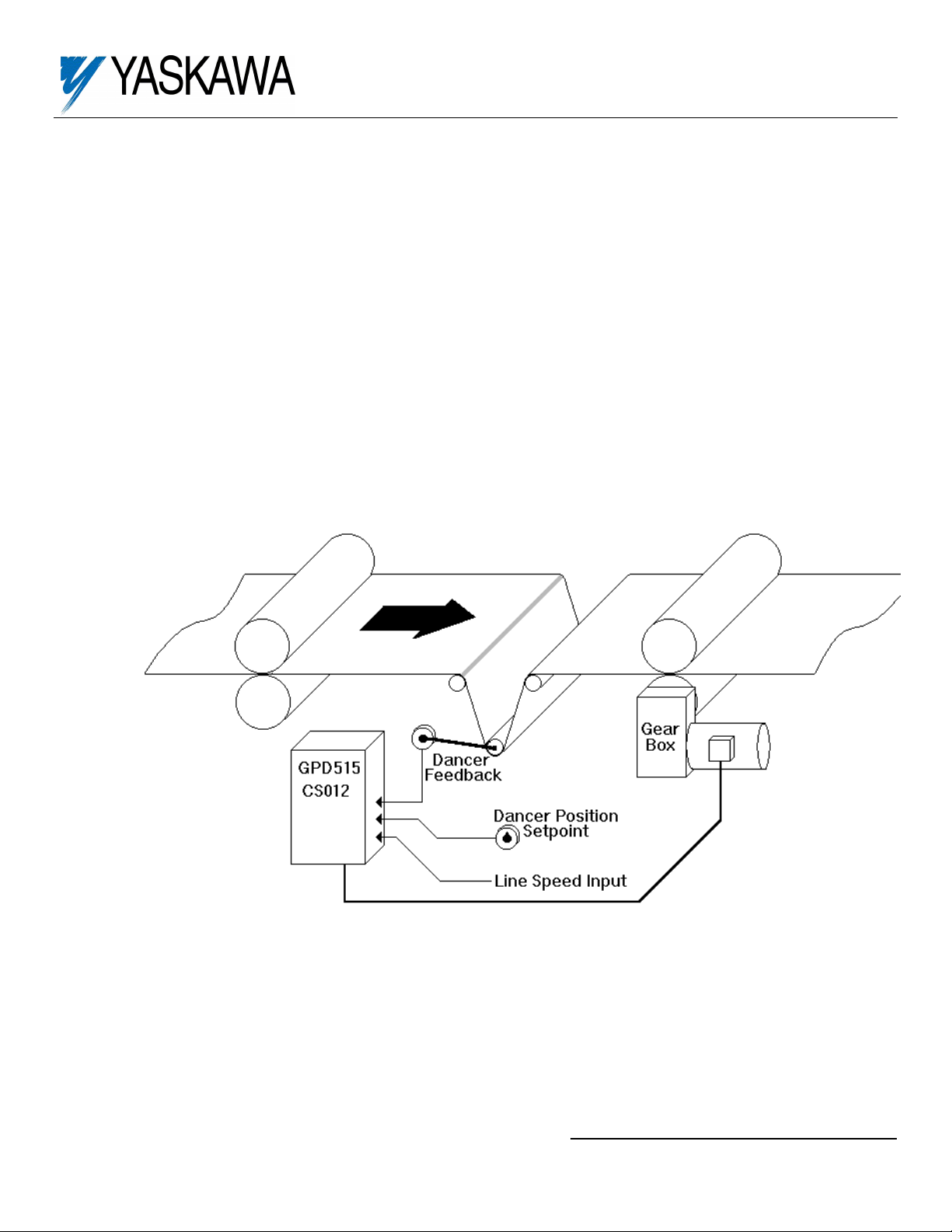
The GPD 51/G5, with this factory-installed
FLASH software, has the capability to “trim” a
speed reference with a PID (Proportional,
Integral, Differential) control algorithm. This
software provides the capability to set a speed
reference, then add or subtract from that speed
reference according to a feedback device;
dancer, position transducer, pressure
transducer, etc.
This document supplements Technical Manual
TM 4515 and describes the effect of this
software on the parameters in the G5 drive.
Flash Software-PID for Trim Control
Specifications:
Part No: GPD515C-ZZZZ-CS012
Available for All GPD515/G5 drives
3 Different PID Modes:
PID output only
PID + Line Speed
PID + Line Speed w/ accel/decel timer
Digital or Analog Setpoint
Inverted PID Output Available
Integral Reset Available
Integral Hold Available
Control Modes: Open Loop Vector,
Flux Vector & V//f
Serial Communications: Modbus RTU,
RS-232 (RS485 w/option card)
Option S12051 for GPD 515/G5
(1)
(1)
ZZZZ refers to the base Model Number of
the drive in which the software is installed.
Yaskawa Electric America, Inc-www.drives.com
02Y00025-0428 Page 1 of 11
Date: 08/23/01
Page 2
Flash Software-PID for Trim Control
PID For Trim Control This section replaces section 5.36
The Proportional, Integral and Derivative control function provides closed-loop control, or regulation of a system process
variable (dancer position, pressure, temperature, etc.). This regulation is accomplished by comparing a feedback signal
to a setpoint reference, which results in an error signal. The PID control algorithm then performs calculations, based upon
the PID parameter settings (b5-01 thru b5-12), on this error signal. The result of the PID algorithm is then used as the
new speed reference, or to trim the existing speed reference.
5.36A. b5-01 : PID Selection
Using this parameter, PID control can be enabled, and the type of PID control can be selected.
Setting Description
0 PID Disabled
1 PID Enabled (Output Only) - PID output becomes the output frequency
2 PID Enabled (Output + Reference) - PID output “trims” the frequency reference
3 PID Enabled (Output + Reference, with accel / decel timer) - PID output “trims” the frequency reference
• If b5-01 is set to 0, no PID function will occur.
• If b5-01 is set to 1, the frequency reference the drive will use will come from the PID control only.
• If b5-01 is set to 2, the frequency reference the drive will use will be the actual frequency reference (Terminal 13 or d1-
01 thru d1-09) plus the output of the PID control. This mode could be used to perform a line speed w/dancer trim
function.
• If b5-01 is set to 3, the frequency reference the drive will use will be the actual frequency reference (Terminal 13 or
d1-01 thru d1-09) plus the output of the PID control. In addition, the accel/decel ramps will change to the settings in
C1-07 & C1-08 after the time specified in b5-08. See description of b5-08 for more details.
5.36B. Line Speed / Frequency Reference Selection
Refer to Section 5.25 - Local/Remote and Reference Selection
the “Auto” speed reference is terminal 13. The “Manual” speed reference is terminal 16, and the “Memory Data” refers to
speed reference parameters d1-01 thru d1-09.
5.36C. PID Setpoint Selection
b5-07: Position Offset
H3-05: Multi-function Analog Input 1
Selection (Term. 16)
H3-09: Multi-function Analog Input 2
Selection (Term. 14)
Select the PID control Setpoint Reference from either the internal digital setting b5-07, or from an analog input (Terminal
16 or 14). Note: if both a digital and an analog setpoint reference are used simultaneously, the two will add together.
• Voltage signal (0 -10 VDC) Terminal 16: Set H3-05 to data “20” and H3-04 to data “0”.
• Voltage signal (-10 to +10 VDC) Terminal 16: Set H3-05 to data “20” and H3-04 to data “1”.
• Current signal (4 to 20 mA) Terminal 14: Set H3-09 to data “20” and H3-08 to data “2”.
• Voltage signal
•
Voltage signal
(2)
GPD515 Technical Manual TM4515
(3)
(0 -10 VDC) Terminal 14: Set H3-09 to data “20” and H3-04 to data “0”.
(3)
(-10 to +10 VDC) Terminal 14: Set H3-09 to data “20” and H3-04 to data “1”.
(2)
in order to select the line speed. NOTE: in Section 5.25,
Option S12051 for GPD 515/G5
(2)
Factory Setting: 0
Range: 0, 1, 2, 3
Factory Setting: 0.00
Range: -10.00 to +10.00V
Factory Setting: 0
Range: 0 - 21
Factory Setting: 1F
Range: 0 - 21
Yaskawa Electric America, Inc-www.drives.com
02Y00025-0428 Page 2 of 11
Date: 08/23/01
Page 3
Flash Software-PID for Trim Control
5.36D. Feedback Signal Selection
H3-05: Multi-function Analog Input 1
Selection (Term. 16)
H3-09: Multi-function Analog Input 2
Selection (Term. 14)
Select the PID control Feedback Signal from external Terminal 14 or 16.
• Voltage signal (0 -10 VDC) Terminal 16: Set H3-05 to data “B” and H3-04 to data “0”.
• Voltage signal (-10 to +10 VDC) Terminal 16: Set H3-05 to data “B” and H3-04 to data “1”.
• Current signal (4 to 20 mA) Terminal 14: Set H3-09 to data “B” and H3-08 to data “2”.
• Voltage signal
• Voltage signal
(3)
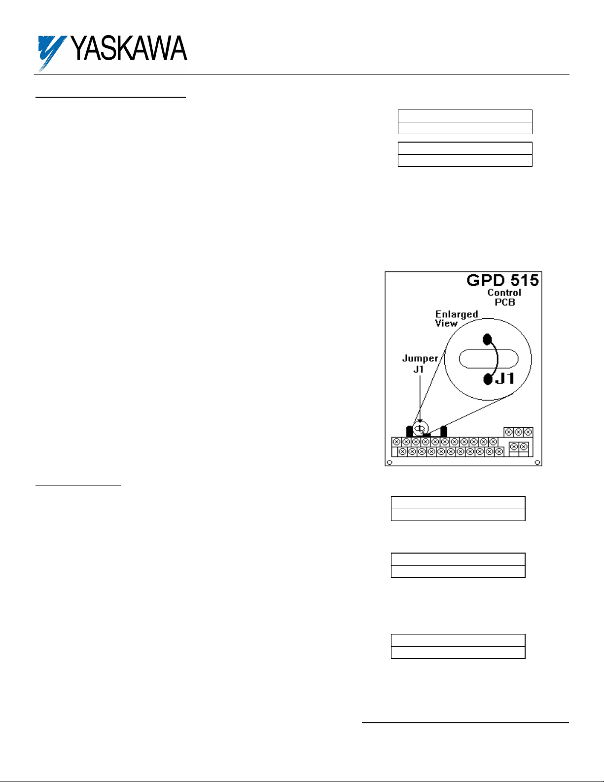
In order to utilize Terminal 14 as a voltage input, a wire jumper needs to be
cut on the main control board. With the input power removed from the drive
and the charge light out, use a small wire cutter to clip the wire labeled J1.
5.36E. PID Settings
b5-02: Proportional Gain
Proportional gain is the value by which the error signal is multiplied to generate a new PID controller output.
b5-03: Integral Time
This parameter determines how fast the PID controller will seek to eliminate any steady-state error. The smaller the
setting, the faster the error will be eliminated. To eliminate the integral function entirely, set this parameter to 0.0 seconds.
b5-04: Integral Limit
This parameter will limit the effect that the integrator can have. It works whether the PID controller output is positive or
negative. It can also be used to prevent integrator “wind-up”.
(3)
(0 -10 VDC) Terminal 14: Set H3-09 to data “B” and H3-04 to data “0”.
(3)
(-10 to +10 VDC) Terminal 14: Set H3-09 to data “B” and H3-04 to data “1”.
Option S12051 for GPD 515/G5
Factory Setting: 0
Range: 0 - 21
Factory Setting: 1F
Range: 0 - 21
Jumper J1 Location
Factory Setting: 1.00
Range: 0.00 - 25.00
Factory Setting: 1.0
Range: 0.0 - 360.0 seconds
Factory Setting: 100
Range: 0.0 - 100.0
Yaskawa Electric America, Inc-www.drives.com
02Y00025-0428 Page 3 of 11
Date: 08/23/01
Page 4

Flash Software-PID for Trim Control
b5-05: Differential Time
Differential time can be adjusted to increase system response to fast load or reference changes, and to reduce overshoot
upon startup. To eliminate the differential function entirely, set this parameter to 0.00 seconds.
b5-06: PID Output Limit
This parameter can be used to set the maximum effect the PID controller will have on the system. This works whether
the PID controller output is positive or negative. NOTE: When the PID output limit is reached, the integrator will hold and
not increase in value until the PID output is less than the PID output limit.
b5-08: Accel/Decel Switching Delay
This parameter sets the amount of time after achieving set speed when the accel/decel ramps will switch between their
present settings and Accel/Decel 4 (C1-07 & C1-08). When a stop command is given, the Accel/Decel ramps will revert
to Accel 1 / Decel 1. This feature is only effective when b5-01 = 3.
Option S12051 for GPD 515/G5
Factory Setting: 0.00
Range: 0.00-10.00 seconds
Factory Setting: 100.00
Range: 0.00 - 100.00
Factory Setting: 0.00
Range: 0.00-10.00 seconds
Timing Chart of Output + Reference, With accel / decel timer (b5-01 =3)
b5-09: PID Output Select
This parameter determines whether the output of the PID controller will be added to or subtracted from the frequency
reference (only when b5-01 = 2 or 3).
Setting Description
0
Not Inverted
1
Inverted
The output of the PID controller will be added to the frequency reference. This would be used when the
output voltage or current of the feedback device increases with motor speed.
The output of the PID controller will be subtracted from the frequency reference. This would used when
the output voltage or current of the feedback device decreases with motor speed.
Factory Setting: 0
Range: 0, 1
Yaskawa Electric America, Inc-www.drives.com
02Y00025-0428 Page 4 of 11
Date: 08/23/01
Page 5

Flash Software-PID for Trim Control
b5-10: PID Position High
b5-11: PID Position Low
b5-12: PID Hysteresis
H2-01: Multi-function Output (Term. 9 & 10)
H2-02: Multi-function Output (Term. 25-27)
H2-03: Multi-function Output (Term. 26-27)
Parameters b5-10, b5-11, and b5-12 are used in conjunction with one or two multi-function outputs. With these a Multifunction Output can be activated when the feedback signal goes above a certain level (b5-10), or drops below a certain
level (b5-11). Parameter b5-12 determines at what point the Multi-function Output will de-energize.
EXAMPLE OF POSITION HIGH AND POSITION LOW OUTPUTS
Option S12051 for GPD 515/G5
Factory Setting: 10.00
Range: -10.00 - +10.00V
Factory Setting: 0.00
Range: -10.00 - +10.00V
Factory Setting: 0.10
Range: 0.00 - 1.00V
Data 40: High Position
or
Data 41: Low Position
Yaskawa Electric America, Inc-www.drives.com
02Y00025-0428 Page 5 of 11
Date: 08/23/01
Page 6

Flash Software-PID for Trim Control
5.36F. H1-01 thru H1-06 : Multi-function Input Terminals
Data 19: PID Control Disable
A multi-function Input Terminal can be used to disable PID control. When this terminal is activated and b5-01 = 2 or 3,
the frequency reference (Terminal 13 or Multi-step speed) is not modified in any way by the PID Controller . When this
terminal is activated and b5-01 = 1, the frequency reference goes to zero.
Data 30: PID Integral Reset
A Multi-function Input Terminal can be used to reset the integrator’s value to zero.
Data 80: Integral Hold
A Multi-function Input Terminal can be used to hold the integrator’s output value. When the contact is closed (on the MultiFunction Input Terminal), whatever value the integrator is outputting will remain the same until the contact is opened.
Data 81: Positive Integral Hold
A Multi-function Input Terminal can be used to keep the integrator’s value from increasing, yet allow it to decrease.
Data 82: Negative Integral Hold
A Multi-function Input Terminal can be used to keep the integrator’s value from decreasing, yet allow it to increase.
The PID parameters are all interactive, and will need to be adjusted until the control loop is properly tuned, i.e. stable with
minimal steady-state error. A general procedure for tuning these parameters is as follows:
1. Adjust Proportional Gain until continuous oscillations in the Controlled Variable are at a minimum.
2. The addition of Integral Time will cause the steady-state error to approach zero. The time should be adjusted so that
this minimal error is attained as fast as possible, without making the system oscillate.
3. If necessary, adjust derivative time to reduce overshoot during startup. The drive’s accel and decel rate times can
also be used for this purpose.
Option S12051 for GPD 515/G5
Yaskawa Electric America, Inc-www.drives.com
02Y00025-0428 Page 6 of 11
Date: 08/23/01
Page 7

This Table Replaces A Portion Of Table A1-2
Flash Software-PID for Trim Control
Option S12051 for GPD 515/G5
(2)
Modbus
Address
Parameter
Number
Function
Name
Description Incre-
ment
Setting
Range
Factory
Setting
Access
Level
(3)
0 1 2 3
b5-01 PID Control
Mode
Selection
0 : Disabled
1 : PID Output Only
2 : PID + Reference
1
0 - 3
0
A
A
A
A
194H
3 : Accel / Decel Time Change
b5-02 PID
Proportional
0.01 0.00 -
25.00
1.00 A A A
A
195H
Gain
b5-03 PID Integral
Time
b5-04 PID Integral
Limit
b5-05 PID
Differential
0.1
sec
0.1% 0.0 -
0.0 -
360.0
1.0 A A A A 196H
100.0 A A A A 197H
100.0
0.01
sec
0.00 -
10.00
0.00 A A A
A
198H
Time
b5-06 PID Output
Limit
b5-07 PID Position
Offset
b5-08 Accel/Decel
Switching
0.01% 0.00 -
100.00 A A A A 199H
100.00
0.01
0.01
sec
V
-10.00 -
10.00
0.00 -
10.00
0.00 A A A A 19AH
0.00 A A A
A
19BH
Delay
b5-09 PID Output
Select
b5-10 PID Position
High
b5-11 PID Position
Low
b5-12 PID
(2)
GPD515 Technical Manual TM4515
(3)
Capability to view and set specific parameters is dependent upon the Access Level (A1-01) and Control Method (A1-02);
Hysteresis
0 : Not Inverted
1 0 - 1 0 A A A A 589H
1 : Inverted
0.01
0.01
0.01
V
V
V
-10.00 -
10.00
-10.00 -
10.00
0.00 -
1.00
10.00 A A A A 587H
0.00 A A A A 588H
0.10 A A A A 586H
0 = V/f, 1 = V/f w/PG, 2 = Open Loop Vector, 3 = Flux Vector) the drive is programmed for. Each column represents the
Access Level for a given Control Method: 0 = Operation only; Q = Quick-start; B - Basic; A = Advanced; - = not available.
Yaskawa Electric America, Inc-www.drives.com
02Y00025-0428 Page 7 of 11
Date: 08/23/01
Page 8

Flash Software-PID for Trim Control
Additions to Table A1-10 (Appendix 1)
Parameter
Number
0 1 2 3
U1-36 Feedback
U1-37 PID Error Difference between setpoint
U1-38 PID Output Output of the PID control
U1-39 Proportional
U1-40 Integral Value Output value of just the integral
U1-41 Derivative
U1-42 PID Setpoint Actual PID setpoint
Monitor Item Description Display
Unit
Feedback Level 0.01 V 10V / 10V
Monitor
0.01% 10V / max.
and feedback
0.01% 10V / max.
algorithm before its added into
the main frequency reference
Value
Output value of just the
proportional portion of the PID
0.01% 10V / max.
algorithm
0.01% 10V / max.
portion of the PID algorithm
Value
Output value of just the
derivative portion of the PID
0.01% 10V / max.
algorithm
0.01V 10V / 10V
(Analog value + b5-07)
Addition to Table 5-2 Multi-Function Input Terminal Data Settings (Section 5.32)
Parameters H1-01 thru H1-06 and terminals 3 thru 8.
Data Function Description Availability
0 1 2 3
30 PID Integral
Reset
Closed = Reset integrator to zero
See Paragraph 5.36F
80 Integral Hold Closed = Hold integrator at its present level
See Paragraph 5.36F
81 Positive
Integral Hold
82 Negative
Integral Hold
Closed = Will allow integrator level to decrease, but not
increase. See Paragraph 5.36F
Closed = Will allow integrator level to increase, but not
decrease. See Paragraph 5.36F
Addition to Table 5-3 Multi-Function Output Terminal Data Settings (Section 5.33)
Parameters H2-01 thru H2-03 and terminals 9, 10, 25, 26 & 27 Plus DO-02C option card F5-01 & F5-02.
Data Condition Signal Level Availability
0 1 2 3
40 High Position
41 Low Position
Closed When PID Feedback is above High position b5-10
Closed When PID Feedback is below Low position b5-11
Addition to Section 5.30 Multi-Function Analog Input Terminal Data Settings
Parameters H3-05 & H3-09 and terminals 16 & 14.
Data Function Description Availability
0 1 2 3
20 PID Setpoint Provides a setpoint signal for use with PID control. X X X X
21 PID Feed-
back Analog
(2)
GPD515 Technical Manual TM4515
Input Bias
Mathematically adds to the feedback signal when using PID
control.
Option S12051 for GPD 515/G5
(2)
Analog Monitor
Output Level
feedback signal
output freq.
(E1-04)
output freq.
(E1-04)
output freq.
(E1-04)
output freq.
(E1-04)
output freq.
(E1-04)
setpoint
Yaskawa Electric America, Inc-www.drives.com
Access
(3)
Level
A A A A
A A A
A
A A A
A
A A A
A
A A A
A
A
A
A
A
A A A A 0E7H
(2)
X X X X
X X X X
X X X X
X X X X
(2)
X X X X
X X X X
(2)
X X X
X
02Y00025-0428 Page 8 of 11
Date: 08/23/01
Modbus
Address
0E1H
0E2H
0E3H
0E4H
0E5H
0E6H
Page 9

Flash Software-PID for Trim Control
Option S12051 for GPD 515/G5
Startup Procedure (typical installation - PID + Line Speed Reference):
1. Follow the appropriate startup procedure in Section 2.2 of the GPD515 Technical Manual TM4515 (2.2a for Open
Loop Vector, 2.2b for Flux Vector, 2.2c for V/f, or 2.2d for V/f with PG Feedback).
2. Calibrate the line speed signal. (using terminal 13 as a 0-10V input)
2a. Determine the required drive output frequency for maximum line speed.
Frequency = Motor RPM* Motor Poles / 120
NOTE: if this option is being applied as a winder with dancer control, use the motor speed when the
winder is at its smallest diameter (core).
2b. Determine the maximum amount of positive trim required as a percentage of line speed.
2c. Set E1-04(maximum output frequency) to the value determined by the following formula:
E1-04 = Frequency
100
NOTE: If the value of E1-04 is less than 60Hz, use 60 instead of the calculated value.
2d. Determine what the line speed signal voltage will be when the line is running at the maximum speed.
2e. Input the voltage determined in step 2d into terminal 13 and adjust parameter H3-02(terminal 13 gain) until
the line speed is correct (while running the drive). NOTE: in order for the drive to respond to the line
speed, the REF light on the digital operator needs to be illuminated. The LOCAL/REMOTE switch will turn
this light on and off.
2f. Stop the drive.
3. Program multi-function analog input 1 (terminal 16) to be PID feedback. The feedback signal can be either +
10V:
+
10V: set H3-04=1 and set H3-05=b (NOTE: a +15VDC power supply is available on terminals 15 & 33)
0-10V: set H3-04=0 and set H3-05=b (NOTE: a 15VDC power supply is available at terminals 15 & 17)
4. Program the drive to accept a PID setpoint. The setpoint for the PID loop can come from one of two places, either a
digitally entered value (b5-07) or an analog value. If a digital value is desired, set the appropriate voltage value into
b5-07. If an analog value is desired, program multi-function analog input 2 (terminal 14) to be a PID setpoint:
10V: clip jumper J1(see Section 5.36D), set H3-08=1 and set H3-09=20
+
0-10V: clip jumper J1(see Section 5.36D), set H3-08=0 and set H3-09=20
4-20mA: set H3-08=2 and set H3-09=20
5. Determine and set PID output polarity.
Program b5-09 = 0 if an increase in feedback voltage level results in a decrease of motor speed.
Program b5-09 = 1 if an increase in feedback voltage level results in an increase of motor speed.
6. Set the appropriate PID mode.
Program b5-01 = 2. When this is programmed, the drive will output a frequency proportional to the algebraic
sum of the line speed signal and the PID algorithm output.
7. Verify all analog signals while the drive is stopped.
7a. Bring up U1-01 on the digital operator and verify that the line speed signal working and correct.
7b. Bring up U1-36 on the digital operator and verify that the feedback voltage is working and correct.
7c. If an analog PID setpoint is being used, bring up U1-42 on the digital operator and verify correct operation.
8. Determine and set the appropriate PID setpoint.
8a. With the drive stopped, bring up U1-36 on the digital operator and then position the feedback device where it
would be while the machine was operating normally. Note the value of U1-36.
8b. If a digital PID setpoint is being used, set the value recorded during step 8a into parameter b5-07. If an
analog PID setpoint is being used, bring up U1-42 on the digital operator and adjust the setpoint until U1-42
matches the value of U1-36 recorded during step 8a.
(@ max line speed)
+ Frequency
(@ max line speed)
* Max. Trim(%)
10V or 0-
Yaskawa Electric America, Inc-www.drives.com
02Y00025-0428 Page 9 of 11
Date: 08/23/01
Page 10

Flash Software-PID for Trim Control
9. Set the maximum amount of trim the PID can output. Program this value into parameter b5-06 (set as a percentage of
the maximum output frequency E1-04) .
NOTE: for most applications, the integral limit (b5-04) needs to be set equal to or less than the setting of b5-06 to
avoid “wind up” of the PID algorithm.
10. (Optional Step) Test operation of the system prior to running product through the machine.
10a. Be sure the DRIVE light on the digital operator is on. To turn the DRIVE light on, press MENU, then
DATA/ENTER.
10b. Be sure the reference is set to remote by verifying that the REMOTE REF light is illuminated. If it is not
illuminated, press the LOCAL/REMOTE key and/or set b1-01 = 1 (terminals)
10c. Start the machine and the drive, then monitor the output frequency U1-02 while moving the feedback
device. As the feedback device is moved, the output frequency of the drive should increase and decrease
the amount specified in step 9.
11. Run the machine while loaded and adjust the PID parameters to achieve the correct response.
11.a Adjust the gain b5-02. Increase = faster response (too much will result in instability). Decrease = slower
response (not enough will result in poor reaction to step changes or impact loads).
11.b Adjust the PID I time b5-03. Decrease = faster response (too low results in instability).
Increase = slower response (too high and recovery from step changes or impact loads will be slow).
11.c Adjust the PID D time b5-05 only if very rapid changes are expected in the system process. Normally this
setting is left at the factory of zero in order to maintain system stability.
11.d Repeat this procedure at different (expected) line speeds in order to find optimum settings)
Verifying Installed Software Number
For the PID for trim control software option, the software number is 12051. The software version installed in the drive can
be verified by either reading it off of the control board, or calling it up on the digital operator.
In order to read the software number off of the control board, take the
cover off of the drive and look for the white sticker on the main control
board. This sticker is just to the right of connector 2CN. On it is the
version of the control board, then a dash, then the software number
(see Figure 1). The “S” before the number can be disregarded.
In order to view the software number from the digital operator, bring up
drive parameter U1-14 (FLASH ID). This is done by powering up the
drive and using the following key sequence:
Option S12051 for GPD 515/G5
, , ,
(13 times)
Software Number Location
Yaskawa Electric America, Inc-www.drives.com
02Y00025-0428 Page 10 of 11
Date: 08/23/01
Page 11

Date: 08/23/01 Page 11 of 11 02Y00025-0428
 Loading...