

Page 1

YASKAWA AC Drive-J1000 Option
RS-485
MEMOBUS/Modbus
Interface
Technical Manual
Type SI-485/J
To properly use the product, read this manual thoroughly and retain
for easy reference, inspection, and maintenance. Ensure the end user
receives this manual.
J1000オプションユニット
MEMOBUS
オプションユニット
取扱説明書
形式 SI-485/J
製品を安全にお使い頂くために,本書を必ずお読みください。
また,本書をお手元に保管していただくとともに,最終的に本製品をご使用になる
ユーザー様のお手元に確実に届けられるよう,お取り計らい願います。
J1000
MANUAL NO. TOBP C730600 33A
通信
Page 2

This Page Intentionally Blank
Page 3

Contents
1 PREFACE AND SAFETY . . . . . . .5
2 RECEIVING . . . . . . . . . . . . . . . . . . 9
3 PRODUCT OVERVIEW . . . . . . . .10
4 OPTION COMPONENTS. . . . . . .11
5 INSTALLATION PROCEDURE . .14
6 RELATED DRIVE PARAMETERS . . .21
7 TROUBLESHOOTING. . . . . . . . .24
8 SPECIFICATIONS . . . . . . . . . . . .26
9 YASKAWA LOCATIONS. . . . . . . 28
10 REVISION HISTORY . . . . . . . . .29
TOBPC73060033A RS-485 Interface Technical Manual 3
Page 4

Copyright © 2008 YASKAWA ELECTRIC CORPORATION
All rights reserved. No part of this publication may be reproduced,
stored in a retrieval system, or transmitted, in any form or by any
means, mechanical, electronic, photocopying, recording, or
otherwise, without the prior written permission of Yaskawa. No
patent liability is assumed with respect to the use of the
information contained herein. Moreover, because Yaskawa is
constantly striving to improve its high-quality products, the
information contained in this manual is subject to change without
notice. Every precaution has been taken in the preparation of this
manual. Yaskawa assumes no responsibility for errors or
omissions. Neither is any liability assumed for damages resulting
from the use of the information contained in this publication.
4 YASKAWA ELECTRIC TOBPC73060033A RS-485 Interface Technical Manual
Page 5
1 Preface and Safety
J1000
1 Preface and Safety
◆ Applicable Documentation
The following manuals are available for the RS-485 Interface
Option:
Option Unit
Yaskawa AC Drive - RS-485
MEMOBUS/Modbus Interface Option
Technical Manual
Read this manual first.
The Technical Manual is packaged with the
RS-485 Interface Option and contains a basic
overview of wiring, settings, functions, and
fault diagnoses.
YASKAWA ELECTRIC TOBPC73060033A RS-485 Interface Technical Ma nual 5
Page 6
1 Preface and Safety
Yaskawa Drive
U.S. and Europe:
Yaskawa AC Drive
J1000 Quick Start
Guide
Other Areas:
Yaskawa AC Drive
J1000 Installation &
Start-Up Manual
Yaskawa AC DriveJ1000
Technical Manual
To obtain instruction
manuals for Yaskawa
products access these
sites:
U.S.: http://
www.yaskawa.com
Europe: http://
www.yaskawa.eu.com
Japan: http://www.emechatronics.com
Other areas: contact a
Yaskawa representative.
For questions, contact the
local Yaskawa sales
office or the nearest
Yaskawa representative.
◆ Terms
Note: Indicates a supplement or precaution that
does not cause drive damage.
Drive: Yaskawa AC Drive - J1000 Series
Option:
6 YASKAWA ELECTRIC TOBPC73060033A RS-485 Interface Technical Manual
Yaskawa AC Drive - J1000 RS-485 MEMOBUS/
Modbus Interface
Page 7

1 Preface and Safety
DANGER
W ARNING
◆ Registered Trademarks
• Company names and product names listed in this manual are
registered trademarks of those companies.
◆ Supplemental Safety Information
Read and understand this manual before installing, operating, or
servicing this option unit. The option unit must be installed
according to this manual and local codes.
The following conventions are used to indicate safety messages in
this manual. Failure to heed these messages could result in serious
or possibly even fatal injury or damage to the products or to related
equipment and systems.
Indicates a hazardous situation, which, if not avoided, will
result in death or serious injury.
Indicates a hazardous situation, which, if not avoided, could
result in death or serious injury.
YASKAWA ELECTRIC TOBPC73060033A RS-485 Interface Technical Ma nual 7
Page 8

1 Preface and Safety
CAUTION
NOTICE
Indicates a hazardous situation, which, if not avoided, could
result in minor or moderate injury.
Indicates an equipment damage message.
8 YASKAWA ELECTRIC TOBPC73060033A RS-485 Interface Technical Manual
Page 9

2 Receiving
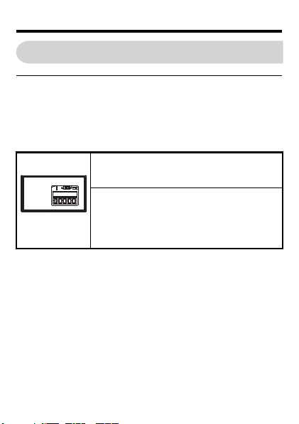
Blade width
3.0 mm max.
0.6 mm max.
Blade thickness
2 Receiving
◆ Receiving
Confirm the packaging after receiving the RS-485 Interface
Option. If the wrong model is received or the RS-485 Interface
Option does not function properly, contact your supplier.
Components packaged with the option:
• The RS-485 MEMOBUS/Modbus Interface (SI-485/J)
• Technical manual
◆ Tool Requirements
Use a flat-blade screwdriver with the dimensions below for
installation (See page 12) or removal (See page 13) of the option
cover and RS-485 Interface Option.
YASKAWA ELECTRIC TOBPC73060033A RS-485 Interface Technical Ma nual 9
Page 10

3 Product Overview
3 Product Overview
◆ About this product
The RS-485 MEMOBUS/Modbus Interface is used to connect the
drive to a network using the MEMOBUS protocol.
By installing this option unit, the user can operate the drive with a
PLC or some other type of control device.
• Drive operation
• Monitor drive operational status
• Change drive parameter settings
◆ Applicable Models
The RS-485 Interface Option is used with these Yaskawa drive
models.
Drive Drive Software Version <1>
CIMR-JABA ≥1010
<1> See “PRG” on the drive nameplate for software version
number.
10 YASKAWA ELECTRIC TOBPC73060033A RS-485 Interface Technical Manual
Page 11

4 Option Components
4 Option Components
A
BC
A – DIP Switch
S2
B–Terminal
Block
C–Option
Model
Number
YASKAWA ELECTRIC TOBPC73060033A RS-485 Interface Technical Ma nual 11
DE
D – Drive
Connector
E – Connection
Tab s
Page 12

4 Option Components
◆ Dimensions
The installed Option Interface adds 23.8 mm (0.94 in) to the total
depth of the drive.
8.8(0.35)
12 YASKAWA ELECTRIC TOBPC73060033A RS-485 Interface Technical Manual
15(0.59)
mm(in)
Page 13

4 Option Components
S– S+ IG R– R+
Top View
Bottom View
◆ Terminal Block
Ter min al Name Description
1 R+ Receive (+)
2 R- Receive (-)
3 IG Shield Ground
4 S+ Send (+)
5S-Send (-)
YASKAWA ELECTRIC TOBPC73060033A RS-485 Interface Technical Ma nual 13
Page 14

5 Installation Procedure
DANGER
NOTICE
5 Installation Procedure
◆ Section Safety
Electrical Shock Hazard
Disconnect all power to the drive, before servicing.
Failure to comply will result in death or serious injury.
Wait at least one minute after all indicators are off. The drive
has internal capacitors that remain charged even after main
power supply is disconnected. The drive charge LED will
extinguish when the DC bus voltage is below 50 Vdc. Measure
drive DC bus voltage to confirm safe level.
Damage to Equipment
Properly connect the connectors.
Failure to comply may prevent proper operation and possibly
damage equipment.
14 YASKAWA ELECTRIC TOBPC73060033A RS-485 Interface Technical Manual
Page 15

5 Installation Procedure
◆ Attaching the Interface Option
1. Insert a flat-blade screwdriver into the
opening as shown in the diagram below to
remove the option cover from the drive.
2. Insert the connector on the back of the
interface into the CN5 port and click into
place.
Note: The RS-485 Interface Option has three additional
connection tabs that must also click into place to
properly mount the option.
Flat-blade
screwdriver
CN5 port
Connection
tabs
YASKAWA ELECTRIC TOBPC73060033A RS-485 Interface Technical Ma nual 15
Page 16

5 Installation Procedure
Underside of
Interface Option
Flat-blade
screwdriver
◆ Removing the Interface Option
1. Insert a flat-blade screwdriver into the
small opening between the drive and the
Interface Option, and gently apply
pressure to the connection tabs as shown.
16 YASKAWA ELECTRIC TOBPC73060033A RS-485 Interface Technical Manual
Page 17

5 Installation Procedure
Drive
SI-485/J
S2
DIP Switch
ON
R+
R–
IG
S+
S–
R+
R–
IG
S+
S–
PLC
◆ Connecting Peripheral Devices to the
RS-485 Interface Option
PLC (Master)
Drive Drive Drive
◆ Wiring Diagram
■ RS-485 Communications (2-wire)
Single Drive Wiring
YASKAWA ELECTRIC TOBPC73060033A RS-485 Interface Technical Ma nual 17
Page 18

5 Installation Procedure
Drive
SI-485/J
S2
DIP Switch
ON
R+
R–
IG
S+
S–
Drive
SI-485/J
S2
R+
R–
IG
S+
S–
Drive
SI-485/J
S2
R+
R–
IG
S+
S–
R+
R–
IG
S+
S–
PLC
DIP Switch
OFF
DIP Switch
OFF
Multiple Drive Wiring
Note: • Set termination resistor switch S2, located
18 YASKAWA ELECTRIC TOBPC73060033A RS-485 Interface Technical Manual
on the SI-485/J Option Interface to the ON
position for the end drive on the network.
• Set parameter H5-07 = 1 for each drive on
the network that is using RS-485
communications.
Page 19

5 Installation Procedure
Drive
SI-485/J
S2
DIP Switch
ON
PLC
R+
R–
IG
S+
S–
R+
R–
IG
S+
S–
■ RS-422 Communications (4-wire)
Single Drive Wiring
YASKAWA ELECTRIC TOBPC73060033A RS-485 Interface Technical Ma nual 19
Page 20

5 Installation Procedure
R+
R–
IG
S+
S–
PLC
Drive
SI-485/J
DIP Switch
OFF
S2
R+
R–
IG
S+
S–
Drive
SI-485/J
S2
R+
R–
IG
S+
S–
Drive
SI-485/J
S2
R+
R–
IG
S+
S–
DIP Switch
OFF
DIP Switch
ON
Multiple Drive Wiring
Note: • Set termination resistor switch S2, located
20 YASKAWA ELECTRIC TOBPC73060033A RS-485 Interface Technical Manual
on the SI-485/J Option Interface to the ON
position for the end drive on the network.
• Set parameter H5-07 = 0 for each drive on
the network that is using RS-422
communications.
Page 21

6 Related Drive Parameters
6 Related Drive Parameters
No. Name Description Default
Selects the frequency
reference input source.
Frequency
b1-01
Reference
Selection 1
Run Command
b1-02
Selection 1
Drive Slave
H5-01
Address
YASKAWA ELECTRIC TOBPC73060033A RS-485 Interface Technical Ma nual 21
0: Operator - Digital preset
speed d1-01 to d1-17.
1 : Terminals - Analog input
terminal A1 or A2.
2: MEMOBUS/Modbus
communications
3: Option PCB
Selects the run command
input source.
0: Operator - RUN and
STOP keys on the digital
operator.
1 : Digital input terminals
2: MEMOBUS
communications
Selects drive slave number
(address) for MEMOBUS/
Modbus terminals R+, R-,
S+, S-. Cycle power for the
setting to take effect.
1
1
1F
Page 22

6 Related Drive Parameters
No. Name Description Default
Selects the baud rate for
MEMOBUS/Modbus
terminals R+, R-, S+ and S-.
Cycle power for the setting
Communication
H5-02
Speed Selection
Communication
H5-03
Parity Selection
Stopping
Method After
H5-04
Communication
Error
22 YASKAWA ELECTRIC TOBPC73060033A RS-485 Interface Technical Manual
to take effect.
0: 1200 bps
1: 2400 bps
2: 4800 bps
3: 9600 bps
4: 19200 bps
5: 38400 bps
Selects the communication
parity for MEMOBUS/
Modbus terminals R+, R-,
S+ and S-. Cycle power for
the setting to take effect.
0: No parity
1: Even parity
2: Odd parity
Selects the stopping method
when a communication
time-out fault (CE) is
detected.
0: Ramp to stop
1: Coast to stop
2: Fast-stop
3: Alarm only
3
0
3
Page 23

6 Related Drive Parameters
No. Name Description Default
Drive Transmit
H5-06
Wait Time
RTS Control
H5-07
Selection
Run Command
H5-12
Method
Selection
MEMOBUS/
Modbus
frequency
H5-13
reference and
frequency
monitor unit
YASKAWA ELECTRIC TOBPC73060033A RS-485 Interface Technical Ma nual 23
Set the wait time between
receiving and sending data.
Selects “request to send”
(RTS) control:
0: Disabled - RTS is always
on.
1: Enabled - RTS turns on
only when sending.
0 : FWD/STOP, REV/STOP
Method
1: RUN/STOP, FWD/REV
Method
0: 0.1 Hz / 1
1: o1-03 based
2: 100% / 30000
3: 0.1% / 1
10 ms
1
0
0
Page 24

7 Troubleshooting
7 Troubleshooting
Problems with the option interface may trigger an operator error.
Refer to the J1000 Technical Manual for all other errors.
◆ Fault
LED Operator
Display
MEMOBUS/Modbus Communication
CE
Error
Cause Possible solutions
Data not received
within the CE
detection time
limit set in
parameter H5-09.
This is possibly
due to noise or a
improperly
connected
communication
cable.
24 YASKAWA ELECTRIC TOBPC73060033A RS-485 Interface Technical Manual
⇒Check for improper wiring or loose
cables.
⇒Make sure the unit is properly grounded.
⇒Reconnect leads running to the main
circuit in the drive.
⇒Make sure the DIP switch for terminal
resistance is set appropriately.
Minor Fault Name
Page 25

7 Troubleshooting
LED Operator
Display
Run Command Selection Error
oPE05
The Run command selection parameter b102 is set to 3 but no option unit is installed.
Cause Possible solutions
Frequency
reference is
assigned to an
option (b1-01 = 2)
that is not
connected to the
drive.
The Run command
is assigned to an
option (b1-02 = 2)
that is not
connected to the
drive.
YASKAWA ELECTRIC TOBPC73060033A RS-485 Interface Technical Ma nual 25
⇒Make sure that parameters b1-01 and b102 are set properly.
⇒Reconnect the option unit to the drive.
Minor Fault Name
Page 26

8 Specifications
8 Specifications
◆ Option Specifications
Item Specification
Model
Number
Storage/
Installation
Area
Ambient
Temperature
Humidity 95% RH or less with no condensation
Storage
Temperature
Altitude 1000 m or less
26 YASKAWA ELECTRIC TOBPC73060033A RS-485 Interface Technical Manual
SI-485/J
Indoors (an area free from oil mist and dust)
-10 to +50°C
-20 to +60°C allowed for short-term transport of
the product
Page 27

8 Specifications
◆ Network Specifications
Item Specification
Interface RS-422, RS-485
Communication
Speeds Available
Communication
Parameters
Protocol MEMOBUS/Modbus (using RTU mode only)
Maximum
Number of
Slaves
YASKAWA ELECTRIC TOBPC73060033A RS-485 Interface Technical Ma nual 27
Data length 8 bit (fixed)
Parity
Stop bit 1 bit (fixed)
31 drives (using RS-485)
1.2; 2.4; 4.8; 9.6;
19.2; 38.4 kbps
Select even, odd, or
none
Page 28

9 Yaskawa Locations
(Address revision No.: 10-10-6)
DRIVE CENTER (INVERTER PLANT)
2-13-1, Nishimiyaichi, Yukuhashi, Fukuoka, 824-8511, Japan
Phone: 81-930-25-3844 Fax: 81-930-25-4369
http://www.yaskawa.co.jp
YASKAWA ELECTRIC CORPORATION
New Pier Takeshiba South Tower, 1-16-1, Kaigan, Minatoku, Tokyo, 105-6891, Japan
Phone: 81-3-5402-4502 Fax: 81-3-5402-4580
http://www.yaskawa.co.jp
YASKAWA AMERICA, INC.
2121 Norman Drive South, Waukegan, IL 60085, U.S.A.
Phone: (800) YASKAWA (927-5292) or 1-847-887-7000 Fax: 1-847-887-7310
http://www.yaskawa.com
YASKAWA ELÉTRICO DO BRASIL LTDA.
Avenda Fagundes Filho, 620 Bairro Saude, São Paulo, SP04304-000, Brasil
Phone: 55-11-3585-1100
Fax: 55-11-5581-8795
http://www.yaskawa.com.br
YASKAWA EUROPE GmbH
Hauptstrasse 185, 65760 Eschborn, Germany
Phone: 49-6196-569-300 Fax: 49-6196-569-398
http://www.yaskawa.eu.com
YASKAWA ELECTRIC UK LTD.
1 Hunt Hill Orchardton Woods, Cumbernauld, G68 9LF, United Kingdom
Phone: 44-1236-735000
Fax: 44-1236-458182
http://www.yaskawa.co.uk
YASKAWA ELECTRIC KOREA CORPORATION
7F, Doore Bldg. 24, Yeoido-dong, Yeoungdungpo-gu, Seoul, 150-877, Korea
Phone: 82-2-784-7844
Fax: 82-2-784-8495
http://www.yaskawa.co.kr
YASKAWA ELECTRIC (SINGAPORE) PTE. LTD.
151 Lorong Chuan, #04-01, New Tech Park, 556741, Singapore
Phone: 65-6282-3003
Fax: 65-6289-3003
http://www.yaskawa.com.sg
YASKAWA ELECTRIC (SHANGHAI) CO., LTD.
No. 18 Xizang Zhong Road, 17F, Harbour Ring Plaza, Shanghai, 200001, China
Phone: 86-21-5385-2200
Fax: 86-21-5385-3299
http://www.yaskawa.com.cn
YASKAWA ELECTRIC (SHANGHAI) CO., LTD. BEIJING OFFICE
Room 1011, Tower W3 Oriental Plaza, No. 1 East Chang An Ave.,
Dong Cheng District, Beijing, 100738, China
Phone: 86-10-8518-4086
Fax: 86-10-8518-4082
YASKAWA ELECTRIC TAIWAN CORPORATION
9F, 16, Nanking E. Rd., Sec. 3, Taipei, 104, Taiwan
Phone: 886-2-2502-5003
Fax: 886-2-2505-1280
9 Yaskawa Locations
28 YASKAWA ELECTRIC TOBPC73060033A RS-485 Interface Technical Manual
Page 29

10 Revision History
MANUAL NO. TOBP C730600 33A
Published in Japan December 2008 08-1
Date of
publication
Date of original
publication
Revision
number
1
123
4
10 Revision History
The revision dates and numbers of the revised manuals are given
on the bottom of the back cover.
Date of
Publication
January 2008 – – First edition
December 2008 Chapter 5
April 2010 Chapter 9 Revision: Address
September 2010 Chapter 9 Revision: Address
July 2011
YASKAWA ELECTRIC TOBPC73060033A RS-485 Interface Technical Ma nual 29
Rev.
Section Revised Content
No.
Correction:
Wiring diagram of RS-422
communications (4-wire)
Front cover,
back cover
Revision: Format
Page 30

YASKAWA AC Drive-J1000 Option
RS-485
MEMOBUS/Modbus
Interface
Technical Manual
J1000オプションユニット
MEMOBUS
オプションユニット
取扱説明書
Any inquiries related to the product can be directed to the address listed at chapter 9.
この製品に関するお問い合わせ先については,9章お問い合わせ先をご覧ください。
In the event that the end user of this product is to be the military and said product is to be employed in any weapons systems or the manufacture
thereof, the export will fall under the relevant regulations as stipulated in the Foreign Exchange and Foreign Trade Regulations. Therefore, be sure to
follow all procedures and submit all relevant documentation according to any and all rules, regulations and laws that may apply.
Specifications are subject to change without notice for ongoing product modifications and improvements.
© 2008-2011 YASKAWA ELECTRIC CORPORATION. All rights reserved.
本製品の最終使用者が軍事関係であったり,用途が兵器などの製造用である場合には,「外国為替及び外国貿易法」の定める輸出規制の対象となることがあります
ので,輸出される際には十分な審査及び必要な輸出手続きをお取りください。
製品改良のため,定格,仕様,寸法などの一部を予告なしに変更することがあります。
通信
YASKAWA ELECTRIC CORPORATION
MANUAL NO. TOBP C730600 33A
Published in Japan July 2011 08-1
4 -0
 Loading...