

Page 1

DX100
1 of 764
MAINTENANCE MANUAL
FOR EUROPEAN STANDARD
Upon receipt of the product and prior to initial operation, read these instructions thoroughly, and retain
for future reference.
MOTOMAN INSTRUCTIONS
MOTOMAN- INSTRUCTIONS
DX100 INSTRUCTIONS FOR EUROPEAN STANDARD
DX100 OPERATOR’S MANUAL
DX100 MAINTENANCE MANUAL FOR EUROPEAN STANDARD
The DX100 operator’s manual above correspond to specific usage.
Be sure to use the appropriate manual.
Part Number: 171768-1CD
Revision: 0
MANUAL NO.
RE-CHO-A109
2
Page 2

DX100 European
2 of 764
Standard Maintenance
171768-1CD
Copyright © 2014, Yaskawa America, Inc. All Rights Reserved.
ii
RE-CHO-A109
Page 3

171768-1CD
MANDATORY
CAUTION
3 of 764
DX100 European
Standard Maintenance
• This instruction manual is intended to explain mainly on the
mechanical part of the DX100 for the application to the actual
operation and for proper maintenance and inspection. It describes
on safety and handling, details on specifications, necessary items
on maintenance and inspection, to explain operating instructions
and maintenance procedures. Be sure to read and understand this
instruction manual thoroughly before installing and operating the
manipulator.
• General items related to safety are listed in Section 1: Safety of the
DX100 Instructions. To ensure correct and safe operation, carefully
read the DX100 Instructions before reading this manual.
• Some drawings in this manual are shown with the protective covers
or shields removed for clarity. Be sure all covers and shields are
replaced before operating this product.
• The drawings and photos in this manual are representative
examples and differences may exist between them and the
delivered product.
• YASKAWA may modify this model without notice when necessary
due to product improvements, modifications, or changes in
specifications.
• If such modification is made, the manual number will also be
revised.
• If your copy of the manual is damaged or lost, contact a YASKAWA
representative to order a new copy. The representatives are listed
on the back cover. Be sure to tell the representative the manual
number listed on the front cover.
• YASKAWA is not responsible for incidents arising from unauthorized
modification of its products. Unauthorized modification voids your
product's warranty.
iii
RE-CHO-A109
Page 4

DX100 European
DANGER
WARNING
CAUTION
MANDATORY
PROHIBITED
NOTE
4 of 764
Standard Maintenance
Notes for Safe Operation
Read this manual carefully before maintenance or inspection of the
DX100.
In this manual, the Notes for Safe Operation are classified as “DANGER”,
“WARNING,” “CAUTION,” “MANDATORY,” or “PROHIBITED.”
171768-1CD
Indicates an imminent hazardous
situation which, if not avoided,
could result in death or serious
injury to personnel.
Indicates a potentially hazardous
situation which, if not avoided,
could result in death or serious
injury to personnel.
Indicates a potentially hazardous
situation which, if not avoided,
could result in minor or moderate
injury to personnel and damage to
equipment. It may also be used to
alert against unsafe practices.
Always be sure to follow explicitly
the items listed under this
heading.
Must never be performed.
Even items described as “CAUTION” may result in a serious accident in
some situations. At any rate, be sure to follow these important items.
To ensure safe and efficient operation at all times, be sure
to follow all instructions, even if not designated as
“DANGER”, “WARNING” and “CAUTION”.
iv
RE-CHO-A109
Page 5

171768-1CD
WARNING
TURN
5 of 764
DX100 European
Standard Maintenance
• Confirm that no person is present in the P-point maximum envelope
of the manipulator and that you are in a safe location before:
– Turning on the power for the DX100.
– Moving the manipulator with the programming pendant.
– Running the system in the check mode.
– Performing automatic operations.
Injury may result if anyone enters the P-point maximum envelope of the
manipulator during operation. Always press an emergency stop button
immediately if there is a problem.
The emergency stop button is located on the right side of the
programming pendant.
• Observe the following precautions when performing teaching
operations within the P-point maximum envelope of the
manipulator:
– Be sure to use a lockout device to the safeguarding when going
inside. Also, display the sign that the operation is being
performed inside the safeguarding and make sure no one closes
the safeguarding.
– View the manipulator from the front whenever possible.
– Always follow the predetermined operating procedure.
– Ensure that you have a safe place to retreat in case of
emergency.
Improper or unintended manipulator operation may result in injury.
• Before operating the manipulator, check that servo power is turned
OFF pressing the emergency stop buttons on the programming
pendant.
When the servo power is turned OFF, the SERVO ON LED on the
programming pendant is turned OFF.
Injury or damage to machinery may result if the emergency stop circuit
cannot stop the manipulator during an emergency. The manipulator
should not be used if the emergency stop buttons do not function.
Figure 1: Emergency Stop Button
• Once the emergency stop button is released, clear the cell of all
items which could interfere with the operation of the manipulator.
Then turn the servo power ON.
Injury may result from unintentional or unexpected manipulator motion.
Figure 2: Release of Emergency Stop
v
RE-CHO-A109
Page 6

DX100 European
CAUTION
6 of 764
Standard Maintenance
171768-1CD
• Perform the following inspection procedures prior to conducting
manipulator teaching. If problems are found, repair them
immediately, and be sure that all other necessary processing has
been performed.
– Check for problems in manipulator movement.
– Check for damage to insulation and sheathing of external wires.
• Always return the programming pendant to the hook on the cabinet
of the DX100 after use.
The programming pendant can be damaged if it is left in the
manipulator's work area, on the floor, or near fixtures.
• Read and understand the Explanation of Warning Labels in the
DX100 Instructions before operating the manipulator:
Definition of Terms Used Often in This Manual
The MOTOMAN manipulator is the YASKAWA industrial robot product.
The manipulator usually consists of the controller, the programming
pendant, and manipulator cables.
In this manual, the equipment is designated as follows:.
Equipment Manual Designation
DX100 Controller DX100
DX100 Programming Pendant Programming Pendant
Cable between the manipulator and the
controller
Manipulator cable
vi
RE-CHO-A109
Page 7

171768-1CD
PAGE
GO BACK
PAGE
GO BACK
7 of 764
DX100 European
Standard Maintenance
Descriptions of the programming pendant keys, buttons, and displays are
shown as follows:
Equipment Manual Designation
Programming
Pendant
Character
Keys
Symbol Keys The keys which have a symbol printed on them
Axis Keys
Numeric Keys
Keys pressed
simultaneously
Displays The menu displayed in the programming
The keys which have characters printed on
them are denoted with [ ].
ex. [ENTER]
are not denoted with [ ] but depicted with a
small picture.
ex. page key
The cursor key is an exception, and a picture is
not shown.
“Axis Keys” and “Numeric Keys” are generic
names for the keys for axis operation and
number input.
When two keys are to be pressed
simultaneously, the keys are shown with a “+”
sign between them.
ex. [SHIFT]+[COORD]
pendant is denoted with { }.
ex. {JOB}
Description of the Operation Procedure
In the explanation of the operation procedure, the expression “Select • • •”
means that the cursor is moved to the object item and the SELECT key is
pressed, or that the item is directly selected by touching the screen.
Registered Trademark
In this manual, names of companies, corporations, or products are
trademarks, registered trademarks, or brand names for each company or
corporation. The indications of (R) and TM are omitted.
vii
RE-CHO-A109
Page 8

DX100 European
X81
PROGRAMMING PENDANT
PROPERLY.
CHECK ALL THE DOOR LOCKS
NJ3005-1
kVA
kVA
ERDR-
Average
Peak
NJ3053-1
Kammerfeldstr. 1, D-85391 Allershausen
Motoman
2-1 Kurosaki Shiroishi Yahatanishi-Ku Kitakyushu-City Fukuoka 806-0004 Japan
YASKAWA Electric corporation
Robot Serial No.
Robot Order No.
Robot Type
Type
Date/Signature
Serial No.
AC 400/415/440 V
Power Supply
Part No.
Motoman DX100
with power ON.
WARNING
Do not open the door
High Voltage
with power ON.
WARNING
High Voltage
Do not open the door
8 of 764
Standard Maintenance
Explanation of Warning Labels
• The label described below is attached to the manipulator.
Observe the precautions on the warning labels.
Failure to observe this caution may result in injury or damage to
equipment.
Refer to the manipulator manual for the warning label location.
Figure 3: Warning Labels
171768-1CD
DANGER
• The following warning labels are attached to DX100.
Observe the precautions on the warning labels.
Failure to observe this warning may result in injury or damage to
equipment.
Figure 4: Warning Label Location
viii
RE-CHO-A109
Page 9

171768-1CD
9 of 764
DX100 European
Standard Maintenance
Table of Contents
Table of Contents
1 Equipment Configuration ................................................................................................................ 1-1
1.1 Arrangement of Units and Circuit Boards .......................................................................... 1-1
1.1.1 Arrangement......................................................................................................... 1-1
1.1.1.1 Small-Capacity DX100 Controller............................................................ 1-1
1.1.1.2 Medium and Large-Capacity DX100 Controller....................................... 1-2
1.2 Power Flow ........................................................................................................................ 1-3
1.3 Signal Flow ........................................................................................................................ 1-4
2 Security System .............................................................................................................................. 2-1
2.1 Protection Through Security Mode Settings ...................................................................... 2-1
2.1.1 Security Mode ...................................................................................................... 2-1
2.1.1.1 Changing the Security Mode ................................................................... 2-6
2.1.2 User ID .................................................................................................................2-8
2.1.2.1 Changing a User ID................................................................................. 2-8
3 Inspections...................................................................................................................................... 3-1
3.1 Regular Inspections ........................................................................................................... 3-1
3.2 DX100 Inspections............................................................................................................. 3-2
3.2.1 Checking if the Doors are Firmly Closed .............................................................. 3-2
3.2.2 Checking for Gaps or Damage in the Sealed Construction Section..................... 3-2
3.3 Cooling Fan Inspections ................................................................................................... 3-3
3.4 Emergency Stop Button Inspections.................................................................................. 3-4
3.5 Enable Switch Inspections.................................................................................................3-4
3.6 Battery Inspections ............................................................................................................ 3-5
3.7 Power Supply Voltage Confirmation .................................................................................. 3-5
3.8 Open Phase Check............................................................................................................ 3-6
4 Preparation before Replacing Parts................................................................................................ 4-1
4.1 Creating a Check Program ................................................................................................ 4-3
ix
RE-CHO-A109
Page 10

171768-1CD
10 of 764
DX100 European
Standard Maintenance
5 Replacing Parts............................................................................................................................... 5-1
5.1 Replacing DX100 Parts...................................................................................................... 5-1
5.1.1 Replacing Parts of the CPU Unit .......................................................................... 5-2
5.1.1.1 Replacing the Battery ..............................................................................5-3
5.1.1.2 Replacing the Control Circuit Board (JANCD-YCP01-E)......................... 5-3
5.1.1.3 Replacing the CPS Unit (JZNC-YPS01-E) .............................................. 5-5
5.1.1.4 Replacing the Robot I/F Board (JANCD-YIF01-oE) ................................ 5-6
5.1.1.5 Replacing the I/O Unit (JZNC-YIU02-E) .................................................. 5-8
5.1.1.6 Replacing the Power Supply Contactor Unit (JZRCR-YPU01-o) ..........5-10
5.1.1.7 Replacing the Brake Control Board (JANCD-YBK01-1E)...................... 5-11
5.1.1.8 Replacing the Machine Safety Unit (JZNC-YSU01-1E)......................... 5-12
5.1.2 Replacing the SERVOPACK .............................................................................. 5-14
5.1.3 Replacing the Converter ..................................................................................... 5-18
5.1.4 Replacing the Major Axes Control Circuit Board (SRDA-EAXA01A).................. 5-22
Table of Contents
5.1.5 Checking and Replacing Fuses.......................................................................... 5-23
5.1.5.1 Power Supply Contactor Unit ................................................................ 5-23
5.1.5.2 I/O Unit .................................................................................................. 5-24
5.1.5.3 Machine Safety Unit .............................................................................. 5-25
5.1.5.4 Brake Control Board.............................................................................. 5-26
5.1.6 Interior Circulation Fan ....................................................................................... 5-27
5.1.6.1 Replacing the Interior Circulation Fan ................................................... 5-27
5.1.6.2 Replacing the Backside Duct Fan ......................................................... 5-28
5.2 DX100 Parts List .............................................................................................................. 5-29
5.3 Supplied Parts List ........................................................................................................... 5-31
5.4 Recommended Spare Parts............................................................................................. 5-32
6 Operations After Replacing Parts.................................................................................................... 6-1
6.1 Home Position Calibration .................................................................................................6-2
6.1.1 Home Position Calibration .................................................................................... 6-2
6.1.2 Calibrating Operation............................................................................................ 6-4
6.1.2.1 Registering All Axes at One Time............................................................ 6-4
6.1.2.2 Registering Individual Axes ..................................................................... 6-5
6.1.2.3 Changing the Absolute Data ................................................................... 6-7
6.1.2.4 Clearing Absolute Data............................................................................ 6-7
6.1.3 Manipulator Home Position................................................................................... 6-9
6.2 Position Deviation Check Using the Check Program....................................................... 6-10
6.3 Checking of the Check Program ...................................................................................... 6-11
6.3.1 Motion of the Check Program ............................................................................. 6-11
6.3.2 Checking of the Check Program......................................................................... 6-11
6.3.3 Home Position Data Correction .......................................................................... 6-12
x
RE-CHO-A109
Page 11

171768-1CD
11 of 764
DX100 European
Standard Maintenance
6.4 Setting the Second Home Position (Check Point) ................................ 6-13
6.4.1 Purpose of Position Check Operation ................................................................ 6-15
6.4.2 Procedure for the Second Home Position Setting (Check Point) ....................... 6-17
6.4.3 Procedure after the Alarm .................................................................................. 6-18
7 System Diagnosis ........................................................................................................................... 7-1
7.1 System Version.................................................................................................................. 7-1
7.2 Manipulator Model ............................................................................................................. 7-1
7.3 Input/Output Status............................................................................................................ 7-2
7.3.1 Universal Input ..................................................................................................... 7-2
7.3.1.1 Universal Input Window........................................................................... 7-2
7.3.1.2 Universal Input Simple Window............................................................... 7-2
7.3.2 Universal Output................................................................................................... 7-3
7.3.2.1 Universal Output Window........................................................................ 7-3
7.3.2.2 Universal Output Simple Window............................................................ 7-3
7.3.2.3 Modifying the Output Status .................................................................... 7-4
Table of Contents
7.3.3 Specific Input ........................................................................................................ 7-5
7.3.3.1 Specific Input Window ............................................................................. 7-5
7.3.3.2 Specific Input Simple Window ................................................................. 7-5
7.3.4 Specific Output ..................................................................................................... 7-6
7.3.4.1 Specific Output Window .......................................................................... 7-6
7.3.4.2 Specific Output Simple Window .............................................................. 7-6
7.3.5 RIN Input .............................................................................................................. 7-7
7.3.5.1 RIN Input Window ................................................................................... 7-7
7.3.6 Signal Number Search ......................................................................................... 7-7
7.3.6.1 Direct Search on the Universal/Specified Input/Output Window ............. 7-8
7.3.6.2 Search from the Menu............................................................................. 7-9
7.3.7 Relay Number Search ........................................................................................ 7-10
7.3.7.1 Direct Search on the Universal/Specified Input/Output Window ........... 7-10
7.3.7.2 Search from the Menu........................................................................... 7-11
7.3.8 Modification of the Signal Name......................................................................... 7-12
7.3.8.1 Direct Modification on the Universal/Specified Input/Output Window ... 7-12
7.3.8.2 Modification from the Menu ................................................................... 7-13
7.4 System Monitoring Time Display ..................................................................................... 7-14
7.4.1 System Monitoring Time Display Window .......................................................... 7-14
7.4.2 Individual Window of the System Monitoring Time Display ................................ 7-15
7.4.3 Clearing the System Monitoring Time Display.................................................... 7-16
xi
RE-CHO-A109
Page 12

DX100 European
12 of 764
Standard Maintenance
7.5 Alarm History ...................................................................................................................7-17
7.5.1 Alarm History Window ........................................................................................ 7-17
7.5.2 Clearing the Alarm History.................................................................................. 7-18
7.6 I/O Message History ........................................................................................................7-19
7.6.1 I/O Message History Window ............................................................................. 7-19
7.6.1.1 Search ................................................................................................... 7-19
7.6.2 Clearing the I/O Message History....................................................................... 7-20
7.7 Position Data When Power is Turned ON/OFF ............................................................... 7-21
7.7.1 Power ON/OFF Position Window ....................................................................... 7-21
7.8 Current Position ............................................................................................................... 7-22
7.8.1 Current Position Window .................................................................................... 7-22
7.9 Servo Monitoring.............................................................................................................. 7-23
Table of Contents
171768-1CD
7.9.1 Servo Monitor Window........................................................................................ 7-23
7.9.1.1 Changing the Monitor Items .................................................................. 7-23
7.9.1.2 Clearing Maximum Torque Data............................................................ 7-25
8 Alarm............................................................................................................................................... 8-1
8.1 Outline of Alarm ................................................................................................................. 8-1
8.2 Alarm Display..................................................................................................................... 8-2
8.2.1 Displaying and Releasing Alarm........................................................................... 8-2
8.2.1.1 Releasing Alarms .................................................................................... 8-2
8.2.2 Special Alarm Display........................................................................................... 8-3
8.3 Display of Alarm Details..................................................................................................... 8-5
8.3.1 Parameter ............................................................................................................. 8-5
8.3.2 Display of Alarm Detail Window........................................................................... 8-5
8.3.3 Transition of Alarm Detail Window........................................................................ 8-7
8.4 Alarm Message List ........................................................................................................... 8-8
9 Error ............................................................................................................................................... 9-1
9.1 Error Message List............................................................................................................. 9-1
9.1.1 System and General Operation ............................................................................9-2
9.1.2 Editing................................................................................................................... 9-6
9.1.3 Job Defined Data .................................................................................................. 9-7
9.1.4 External Memory Equipment .............................................................................. 9-11
9.1.5 Concurrent I/O .................................................................................................... 9-16
9.1.6 Maintenance Mode ............................................................................................. 9-18
xii
RE-CHO-A109
Page 13

171768-1CD
13 of 764
DX100 European
Standard Maintenance
9.2 Particular Error Message ................................................................................................. 9-20
9.2.1 Message............................................................................................................. 9-20
9.2.1.1 Fatal Error ............................................................................................. 9-20
9.2.1.2 Application Transaction Error ................................................................ 9-20
9.2.1.3 Other Errors .......................................................................................... 9-21
9.2.2 When the Error is Indicated ................................................................................ 9-22
9.2.2.1 Fatal Error ............................................................................................. 9-22
9.2.2.2 Application Transaction Error ................................................................ 9-22
9.2.2.3 Other Errors .......................................................................................... 9-22
10 LED Indicator on Circuit Board .................................................................................................. 10-1
10.1 LED Indicator on YCP 01 Circuit Board......................................................................... 10-1
10.2 LED Indicator on Robot I/F Circuit Board ...................................................................... 10-2
10.3 7 SEG-LED Indicator ..................................................................................................... 10-3
10.3.0.1 7 SEG-LED Indicator Status (1-digit indication)
10.3.0.2 7 SEG-LED Indicator Status (4 digit-indication)
Table of Contents
of Each Unit at Error Occurrence ........................................................ 10-4
of Each Unit at Error Occurrence ....................................................... 10-5
11 Trouble Shooting When Alarm is not Displayed ......................................................................... 11-1
xiii
RE-CHO-A109
Page 14

DX100 European
JZRCR-YPU01-1
Interior circulation fan:
4715MS-22T-B5A-B00
194E-A40-1753-6G
JANCD-YIF01-1E
JZNC-YPS01-E
JZNC-YRK01-1E
JZNC-YIU02-E
JZNC-YSU01-1E
Backside duct fan:
4715MS-22T-B5A-B00
A
A
A-A’ Section
Inside View of Door
Front View
Inside the Controller
Back View
(without cover)
Power supply
contractor unit
CPS Unit
CPU Unit
Machine safety unit
Robot I/F board
I/O Unit
Main power switch
(-X18)
Robot system
input terminal
block
SERVOPACK:
Refer to the
following table.
JANCD-YBK01-1E
Brake control board
14 of 764
Standard Maintenance
1 Equipment Configuration
1.1 Arrangement of Units and Circuit Boards
1 Equipment Configuration
The DX100 is comprised of individual units and modules (circuit boards).
Malfunctioning components can generally be easily repaired after a failure
by replacing a unit or a module. This section explains the configuration of
the DX100 equipment.
1.1 Arrangement of Units and Circuit Boards
1.1.1 Arrangement
The arrangements of units and circuit boards in small-capacity, mediumcapacity, and large-capacity DX100s are shown.
1.1.1.1 Small-Capacity DX100 Controller
Fig. 1-1: Configuration of Small Capacity DX100
171768-1CD
Model DX100 SERVOPACK (Converter Integrated)
MH5L ERDR-MH00005-E02 JZRCR-YSV01-11
MH5
MH6 ERDR-MH00006-E02 JZRCR-YSV02-11
MA1400 ERDR-MA01400-E02
JZRCR-YSV02-11
ERDR-MA01400-E04
(without JANCD-YEW01-E)
VA1400 ERDR-VA01400-E02
JZRCR-YSV02-31
ERDR-VA01400-E04
(without JANCD-YEW01-E)
MA1900 ERDR-MA01900-E02
ERDR-MA01900-E04
(without JANCD-YEW01-E)
HP20D ERDR-HP0020D-E02 JZRCR-YSV03-11
HP20D-6
HP20RD
JZRCR-YSV03-11
1-1
RE-CHO-A109
Page 15

171768-1CD
4715MS-22T-B5A-B00
A
A
JZRCR-YPU01-1
A-A’ Section
Inside View of Door
Front View
Inside the Controller
Power supply
contactor unit
(-X18)
Robot system
input terminal
block
SERVOPACK:
Refer to the
following table.
Interior circulation fan:
4715MS-22T-B5A-B00
194E-A40-1753-6G
JANCD-YIF01-1E
JZNC-YPS01-E
JZNC-YRK01-1E
JANCD-YBK01-1E
JZNC-YIU02-E
JZNC-YSU01-1E
Back View
(without cover)
Backside duct fan:
Main power switch
CPS Unit
CPU Unit
Machine safety unit
Robot I/F board
I/O Unit
Brake control board
15 of 764
DX100 European
Standard Maintenance
1 Equipment Configuration
1.1 Arrangement of Units and Circuit Boards
1.1.1.2 Medium and Large-Capacity DX100 Controller
Fig. 1-2: Configuration of Medium and Large Capacity DX100
Model DX100 SERVOPACK Converter
MH50 ERDR-MH00050-E02 JZRCR-YSV04-11 SRDA-COA30A01A-E
MH50-20
MH50-35
MS80 ERDR-MS00080-E02 JZRCR-YSV05-11 SRDA-COA30A01A-E
VS50 ERDR-VS00050-E02 JZRCR-YSV05-41 SRDA-COA30A01A-E
SIA50D ERDR-SIA050D-E02 JZRCR-YSV05-41 SRDA-COA30A01A-E
MA1800 ERDR-MA01800-E02
ES165D ERDR-ES0165D-E02 JZRCR-YSV06-11 SRDA-COA30A01A-E
ES200D ERDR-ES0200D-E02 JZRCR-YSV06-11 SRDA-COA30A01A-E
ES165RD ERDR-ES165RD-E02 JZRCR-YSV06-11 SRDA-COA30A01A-E
ES200RD ERDR-ES200RD-E02 JZRCR-YSV06-11 SRDA-COA30A01A-E
HP165D ERDR-HP0165D-E02 JZRCR-YSV06-11 SRDA-COA30A01A-E
UP350D ERDR-UP0350D-E02 JZRCR-YSV07-11 SRDA-COA30A01A-E
JZRCR-YSV08-11 SRDA-COA30A01A-E
ERDR-MA01800-E04
(without JANCD-YEW01-E)
1-2
RE-CHO-A109
Page 16

DX100 European
(2.5A)4FU
(2.5A)3FU
(10A)
(10A)
2FU
1FU
(SRDA-EAXA01A)
DC24V
(Brake)
DC24V
DC24V
DC24V
DC24V
DC24V
(SRDA-COA )
(JZNC-YPS01-E)
(JZNC-YRK01-1E)
(JZNC-YIU02-E)
(JZNC-YSU01-1E)
(JANCD-YBK01-1E)
Power supply contactor unit (JZRCR-YPU01-1)
X81
(+24V1)
CN209
(+24V3)
CN400
+24V2)
CN584
CN583
CN584
CN583
CN584
CN583
CN584
CN583
CN584
CN583
CN404
(+24VU)
(+24V3)
CN403
(+24V1)
(+24V1
/
CN510
CN508
CN509
AMP6
AMP5
AMP4
AMP3
AMP2
CN551
CN556CN552
CN555
CN554
AMP1
CN584
CN583
+24VU)
(+24V2
/
(+24V2)
CN304
CN303
CN305
(+24V1/+24V2)
CN200
(+24V2)
CN158
+24V2 )
(+24V1/
CN5
CN2
CN1
Control circuit board
BACK BOARD
JANCD-YBB01
BATTERY
CN110
JANCD-YIF01- E
CNBUS
ROBOT I/F BOARD
JANCD-YCP01-E
CN1A/1B
(+5V)
+24V2 )
(+24V1/
CN157
CN154
(AC200V IN)
CN151
(+24V3)
CN153
CN155
(+24V2)
CN156
CN159
CN604
CN603
CN606
CN602
2KM
2KM1KM
10A
AC250V
1KM
E
E
E
CN582
CN582
CN582
CN582
CN582
CN582
-G1
-G3
-G4
E
-G2
- AE2
- AE3
- AE1
- AE7
- AE4
- AE5
- TP1
- AE6
- TA1
- TA2
- TA3
- TA4
- TA5
- TA6
L2(S)
L1(R)
PE
L3(T)
-X4
1
2
CN601
3
2
4
1
3
- Q1M
6
5
2
4
1
3
- FS1
6
5
L1’
L2’
- V1
L3’
L1
L2
L3
u
v
- T1
w
U
V
W
3 phase
400 VAC 50/60 Hz
Filter
CPS Unit
Backside duct fan
Interior circulation fan
CPU Unit
Machine safety unit
Programming pendant
Brake control board
Major axes control circuit board
Converter
Manipulator
SERVOPACK
I O Unit
SGDR-FBA A
24V(IN)
5V(OUT)
Brake
Power
Brake
Power
Brake
Power
Brake
Power
Brake
Power
Brake
Power
T-axis motor
B-axis motor
R-axis motor
U-axis motor
L-axis motor
S-axis motor
16 of 764
Standard Maintenance
171768-1CD
1 Equipment Configuration
1.2 Power Flow
1.2 Power Flow
1-3
RE-CHO-A109
Page 17

(SRDA-EAXA01A)
(SRDA- )
(SRDA-COA )
(JANCD-YBK01-1E)
(JZNC-YSU01-1E)
(JZNC-YRK01-1E)
(JZNC-YPS01-E)
Power supply contactor unit (JZRCR-YPU01-1)
(JZRCR-YPP01-
)
I/O=8/8
I
/
O=8/8
I
/
O=12/12
I
/
O=12/12
(JZNC-YIU02-E)
CN607
CN608
RY1 RY2
CN602
1KM
CN601
2KM
CN203CN202
CN209
CN216
CN212
CN211
CN210
CN214
CN208
- X18
CN103
(RS232C)
CN101
(RS422)
CN102
(RS232C)
CN105
(LAN:PP)
(LAN:Ethernet)
CN104
CN581
CN581
CN581
CN581
CN581
CN405
CN402
SHOCK.LAMP
OT
X81
CN512
CN518
CN517
CN516
CN515
CN511
CN513
AMP6
AMP5
AMP4
AMP3
AMP2
AMP1
CN581
CN553
CN507
CN502
CN504
CN506
CN501
CN503
CN505
CN508
(I/O I/F)
CN300
CN309
CN308
CN307
CN306
CN5
CN2
CN1
Control circuit board
BACK BOARD
JANCD-YBB01
BATTERY
CN110
CN113
JANCD-YIF01- E
CN114
CNBUS
ROBOT I/F BOARD
JANCD-YCP01-E
CN1A/1B
CN159
- AE2
- AE3
- AE1
- AE7
- AE4
- AE5
- TP1
- AE6
- TA1
- TA2
- TA3
- TA4
- TA5
- TA6
CPS Unit
I/O Unit
Terminal resistor
(Universal I/O)
(Robot system input terminal block)
Machine safety unit
Terminal resistor
(P.P.
Emergency stop signal)
(Specified I/O)
(Lump)
(External axis overrun)
(Emergency stop signal)
(Overrun)
CPU Unit
Brake control board
Programming pendant
Manipulator
S-axis
motor
L-axis
motor
U-axis
motor
R-axis
motor
B-axis
motor
T-axis
motor
(Optional )
Major axes control circuit board
SERVOPACK
Converter
Terminal resistor
(Shock sensor)
17 of 764
171768-1CD
DX100 European
Standard Maintenance
1 Equipment Configuration
1.3 Signal Flow
1.3 Signal Flow
1-4
RE-CHO-A109
Page 18

DX100 European
18 of 764
Standard Maintenance
2 Security System
2.1 Protection Through Security Mode Settings
2 Security System
2.1 Protection Through Security Mode Settings
The DX100 modes setting are protected by a security system. The system
allows operation and modification of settings according to operator
clearance. Be sure operators have the correct level of training for each
level to which they are granted access.
2.1.1 Security Mode
There are three security modes. Editing mode and management mode
require a user ID. The user ID consists of numbers and letters, and
contains no less than 4 and no more than 8 characters. (Significant
numbers and signs: “0 to 9”, “-”, “.”.
171768-1CD
Security Mode Explanation
Operation Mode This mode allows basic operation of the robot (stopping,
starting, etc.) for people operating the robot work on the
line.
Editing Mode This mode allows the operator to teach and edit jobs and
robot settings.
Management
Mode
This mode allows those authorized to set up and maintain
robot system: parameters, system time and modifying user
IDs.
2-1
RE-CHO-A109
Page 19

171768-1CD
19 of 764
DX100 European
Standard Maintenance
2 Security System
2.1 Protection Through Security Mode Settings
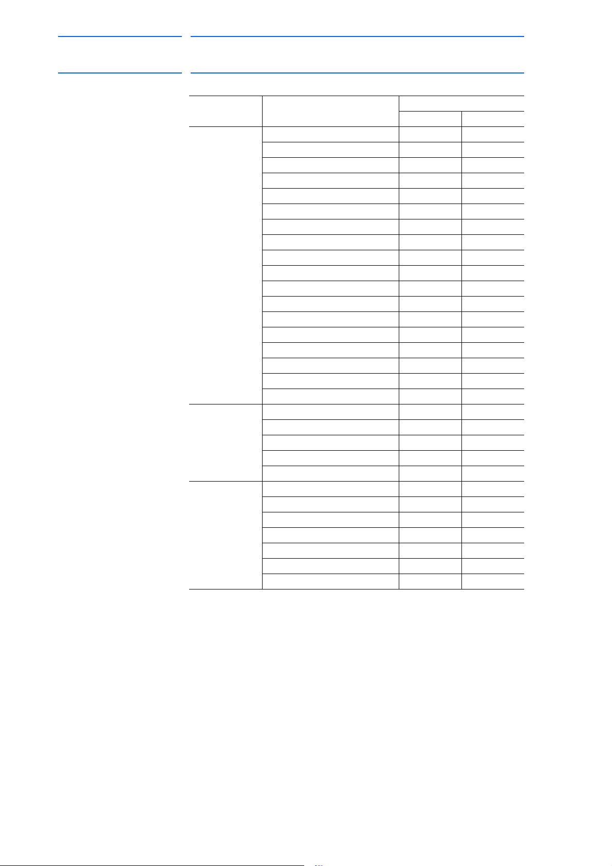
Table 2-1: Menu & Security Mode (Sheet 1 of 4)
Main Menu Sub Menu Allowed Security Mode
DISPLAY EDIT
JOB JOB Operation Edit
SELECT JOB Operation Operation
CREATE NEW JOB
MASTER JOB Operation Edit
JOB CAPACITY Operation -
RES. START (JOB)
RES. STATUS
CYCLE Operation Operation
VARIABLE BYTE Operation Edit
INTEGER Operation Edit
DOUBLE Operation Edit
REAL Operation Edit
STRING Operation Edit
POSITION (ROBOT) Operation Edit
POSITION (BASE) Operation Edit
POSITION (ST) Operation Edit
LOCAL VARIABLE Operation -
IN/OUT EXTERNAL INPUT Operation Edit
EXTERNAL OUTPUT Operation Edit
UNIVERSAL INPUT Operation Operation
UNIVERSAL OUTPUT Operation Operation
SPECIFIC INPUT Operation -
SPECIFIC OUTPUT Operation -
RIN Operation -
CPRIN Operation -
REGISTER Operation Management
AUXILIARY RELAY Operation -
CONTROL INPUT Operation -
PSEUDO INPUT SIG Operation Management
NETWORK INPUT Operation -
NETWORK OUTPUT Operation -
ANALOG OUTPUT Operation -
SV POWER STATUS Operation -
LADDER PROGRAM Management Management
I/O ALARM Management Management
I/O MESSAGE Management Management
1)
1)
2)
Edit Edit
Edit Edit
Operation -
2-2
RE-CHO-A109
Page 20
DX100 European
20 of 764
Standard Maintenance
171768-1CD
2 Security System
2.1 Protection Through Security Mode Settings
Table 2-1: Menu & Security Mode (Sheet 2 of 4)
Main Menu Sub Menu Allowed Security Mode
DISPLAY EDIT
ROBOT CURRENT POSITION Operation -
COMMAND POSITION Operation -
SERVO MONITOR Management -
WORK HOME POS Operation Edit
SECOND HOME POS Operation Edit
DROP AMOUNT Management Management
POWER ON/OFF POS Operation -
TOOL Edit Edit
INTERFERENCE Management Management
SHOCK SENS LEVEL Operation Edit
USER COORDINATE Edit Edit
HOME POSITION Management Management
MANIPULATOR TYPE Management -
ANALOG MONITOR Management Management
OVERRUN&S-SENSOR
LIMIT RELEASE
ARM CONTROL
SHIFT VALUE Operation -
SYSTEM INFO VERSION Operation -
MONITORING TIME Operation Management
ALARM HISTORY Operation Management
I/O MSG HISTORY Operation Management
SECURITY Operation Operation
EX.MEMORY LOAD Edit -
SAVE Operation -
VERIFY Operation -
DELETE Operation -
DEVICE Operation Operation
FOLDER Edit Management
INITIALIZE
1)
1)
1)
1)
Edit Edit
Edit Edit
Management Management
Operation -
2-3
RE-CHO-A109
Page 21

171768-1CD
21 of 764
DX100 European
Standard Maintenance
2 Security System
2.1 Protection Through Security Mode Settings
Table 2-1: Menu & Security Mode (Sheet 3 of 4)
Main Menu Sub Menu Allowed Security Mode
DISPLAY EDIT
PARAMETER S1CxG Management Management
S2C Management Management
S3C Management Management
S4C Management Management
A1P Management Management
A2P Management Management
A3P Management Management
A4P Management Management
A5P Management Management
A6P Management Management
A7P Management Management
A8P Management Management
RS Management Management
S1E Management Management
S2E Management Management
S3E Management Management
S4E Management Management
S5E Management Management
S6E Management Management
S7E Management Management
S8E Management Management
SETUP TEACHING COND. Edit Edit
OPERATE COND. Management Management
OPERATE ENABLE Management Management
FUNCTION ENABLE Management Management
JOG COND. Management Management
PLAYBACK COND. Management Management
FUNCTION COND. Management Management
DATE/TIME Management Management
DISPLAY
SETUP
GRP COMBINATION
RESERVE JOB NAME Edit Edit
USER ID Edit Edit
SET SPEED Management Management
KEY ALLOCATION Management Management
JOG KEY ALLOC. Edit Management
RES. START (CNCT) Management Management
AUTO BACK SET Management Management
WRONG DATA LOG Edit Management
ENERGY SAVING FUNCTION Edit Management
CHANGE FONT Operation Operation
CHANGE BUTTON Operation Operation
INITIALIZE LAYOUT Operation Operation
CHANGE WINDOW PATTERN Operation Operation
2)
Management Management
2-4
RE-CHO-A109
Page 22

DX100 European
22 of 764
Standard Maintenance
171768-1CD
2 Security System
2.1 Protection Through Security Mode Settings
Table 2-1: Menu & Security Mode (Sheet 4 of 4)
Main Menu Sub Menu Allowed Security Mode
DISPLAY EDIT
ARC WELDING ARC START COND. Operation Edit
ARC END COND. Operation Edit
ARC AUX COND. Operation Edit
POWER SOURCE COND. Operation Edit
ARC WELD DIAG. Operation Edit
WEAVING Operation Edit
ARC MONITOR Operation Edit
ARC MONITOR (SAMPL) Operation -
HANDLING HANDLING DIAGNOSIS Operation Edit
SPOT
WELDING
SPOT
WELDING
(MOTOR GUN)
GENERAL WEAVING Operation Edit
COMMON TO
ALL
APPLICATIONS
1 Displayed in the teach mode only.
2 Displayed in the play mode only.
WELD DIAGNOSIS Operation Edit
I/O ALLOCATION Management Management
GUN CONDITION Management Management
SPOT POWER SOURCE
COND.
APPLICATION CONDITION
SETTING
WELD DIAGNOSIS Operation Edit
GUN PRESSURE Edit Edit
PRESSURE Edit Edit
I/O ALLOCATION Management Management
GUN CONDITION Management Management
CLEARANCE SETTING Operation Edit
SPOT POWER SOURCE
COND.
TIP INSTALLATION Operation Management
APPLICATION SETTING Management Management
GENERAL DIAG. Operation Edit
I/O VARIABLE CUSTOMIZE Operation Operation
Management Management
Management Management
Management Management
2-5
RE-CHO-A109
Page 23
171768-1CD
23 of 764
DX100 European
Standard Maintenance
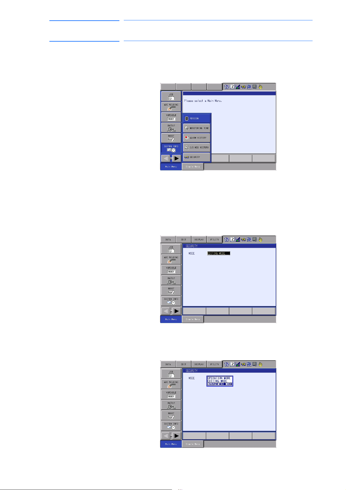
2.1.1.1 Changing the Security Mode
2 Security System
2.1 Protection Through Security Mode Settings
1. Select {SYSTEM INFO} under the main menu.
– The sub menu appears.
– Note: Icons for the main menu such as arc welding system differ
depending on the system being used.
2. Select {SECURITY}.
– The selection window of security mode appears.
3. Press [SELECT] and select “SEC
URITY MODE”
2-6
RE-CHO-A109
Page 24

DX100 European
SUPPLE-
MENT
24 of 764
Standard Maintenance
171768-1CD
2 Security System
2.1 Protection Through Security Mode Settings
4. Input the user ID.
– The user ID input window appears.
At the factory, the following below user ID number is preset.
• Editing Mode:[00000000]
Management Mode:[99999999]
5. Press [ENTER].
– The input user ID is compared with the user ID of the selected
security mode. When the correct user ID is entered, the security
mode is changed.
2-7
RE-CHO-A109
Page 25

171768-1CD
25 of 764
DX100 European
Standard Maintenance
2.1.2 User ID
2.1.2.1 Changing a User ID
2 Security System
2.1 Protection Through Security Mode Settings
User ID is requested when Editing Mode or Management Mode is
operated.
User ID must be between 4 characters and 8, and they must be numbers
and symbols. (“0 to 9”,“-” and “.”)
In order to change the user ID, the DX100 must be in Editing Mode or
Management Mode. Higher security modes can make changes the user
ID of to lower security modes.
1. Select {SETUP} under the main menu.
– The sub menu appears.
2. Select {USER ID}.
– The USER ID window appears.
2-8
RE-CHO-A109
Page 26

DX100 European
26 of 764
Standard Maintenance
171768-1CD
2 Security System
2.1 Protection Through Security Mode Settings
3. Select the desired ID.
– The character input line appears, a
no. (4 to 8 digits)” is shown.
4. Input current ID and press [ENTER].
– When the correct user ID is entered, a new ID is requested to be
in
put. “Input new ID no.(4 to 8 digits)” appears.
nd the message “Input current ID
5. Input new ID and press [ENTER].
– User ID is changed.
2-9
RE-CHO-A109
Page 27

171768-1CD
WARNING
27 of 764
DX100 European
Standard Maintenance
3 Inspections
3.1 Regular Inspections
3 Inspections
3.1 Regular Inspections
• Do not touch the cooling fan or other equipment while the power is
turned ON.
Failure to observe this caution may result in electric shock or injury.
Carry out the following inspections.
Inspection
Equipment
DX100 Controller Check that the doors
Interior circulation
fan and backside
duct fan
Emergency stop
button
Enable switch Check operation As required In teach mode
Battery Confirm battery
Power Supply Check power supply
Inspection Item Inspection
Frequency
Daily
are completely
closed
Check for gaps or
damage to the
sealed construction
Check operation As required While power ON
Check operation As required While servo ON
alarm or message is
displayed or not
voltage is normal
Monthly
As required
As required
Comments
Lead Cables for
main power switch
Check falling out,
loosing or breaking
of the lead cables
Check the correlate
voltage
3-1
As required
RE-CHO-A109
Page 28

DX100 European
X81
PROGRAMMING PENDANT
PROPERLY.
CHECK ALL THE DOOR LOCKS
NJ3005-1
kVA
kVA
ERDR-
Average
Peak
NJ3053-1
Kammerfeldstr. 1, D-85391 Allershausen
Motoman
2-1 Kurosaki Shiroishi Yahatanishi-Ku Kitakyushu-City Fukuoka 806-0004 Japan
YASKAWA Electric corporation
Robot Serial No.
Robot Order No.
Robot Type
Type
Date/Signature
Serial No.
AC 400/415/440 V
Power Supply
Part No.
Motoman DX100
with power ON.
WARNING
Do not open the door
High Voltage
X81
PROGRAMMING PENDANT
PROGRAMMING PENDANT
Main power switch
Door lock
X 8 1
28 of 764
Standard Maintenance
3.2.1 Checking if the Doors are Firmly Closed
171768-1CD
3 Inspections
3.2 DX100 Inspections
3.2 DX100 Inspections
• The DX100 has a fully sealed construction, designed to keep
external air containing oil mist out of the DX100.
Be sure to keep the DX100 doors fully closed at all times, even when
the controller is not operating.
• When opening or closing the doors for maintenance, use the specific
key for this operation after the main power is turned OFF with the
main power switch. (CW: Open, CCW: Close)
Make sure to push the door and turn the door-lock with the specific
key to open or close the door. When closing the door, turn the door
lock until it clicks.
Fig. 3-1: DX100 Front View
3.2.2 Checking for Gaps or Damage in the Sealed Construction Section
• Open the door and check that the seal around the door is
undamaged.
• Check that the inside of the DX100 is not stained badly. If it is,
determine the cause, take measures and immediately clean it.
• Firmly lock each door and check that no excessive gaps exist around
the edge of the door.
3-2
RE-CHO-A109
Page 29

171768-1CD
NOTE
Air intake
Air outlet
Backside duct fan
Interior circulation fan
29 of 764
DX100 European
Standard Maintenance
3 Inspections
3.3 Cooling Fan Inspections
3.3 Cooling Fan Inspections
Inspect the cooling fans as required. A defective fan can cause the DX100
to malfunction because of excessive high temperatures inside.
The interior circulation fan and backside duct fan normally operate while
the power is turned ON. Check if the fans are operating correctly by visual
inspection and by feeling air moving into the air inlet and from the outlet.
Fig. 3-2: Cooling Fan Construction
When the message of the “Cooling fan in YPS power supply
stopped. Exchange fan” is displayed, it may be caused by
the error occurrence at the cooling fan (JZNC-YZU01-E)
inside CPU unit (JZNC-YPS01-E).
When the message of the “Cooling fan in YPS unit stopped,
replace cooling fan” is displayed, carry out an inspection
and the replacement of the cooling fan in the CPS unit
(JZNC-YPS01-E) as soon as possible.
3-3
RE-CHO-A109
Page 30

DX100 European
NOTE
REMOTE
TEACH
PLAY
SERVO
ON
READY
SERVO ON
Blinking
30 of 764
Standard Maintenance
3 Inspections
3.4 Emergency Stop Button Inspections
3.4 Emergency Stop Button Inspections
The emergency stop button is located on the programming pendant.
Before operating the manipulator, confirm the servo power is OFF by
pressing the emergency stop button after the servo ON
3.5 Enable Switch Inspections
The programing pendant is equipped with a three-position enable switch.
Perform the following operation to confirm the enable switch operates.
1. Set the mode switch with key on the programming pendant to
"TEACH."
Mode switch with key
171768-1CD
2. Press [SERVO ON READY] on the programming pendant. The
[SERVO ON] lamp blinks.
3. When the enable switch is grasped lightly, the servo power is turned
ON.
When the enable switch is grasped fir
mly or released, the servo power
is turned OFF.
If the [SERVO ON] lamp does not light in previous operation
(2), check the following:
• The emergency stop button on the programming pendant
is being pressed.
• The emergency stop signal is input from external.
• If a major alarm is occurring.
3-4
RE-CHO-A109
Page 31
171768-1CD
Main power switch part
in the controller
135
24 6
31 of 764
DX100 European
Standard Maintenance
3 Inspections
3.6 Battery Inspections
3.6 Battery Inspections
The DX100 has a battery that backs up the important program files for
user data in the CMOS memory.
A battery alarm indicates when a battery has expired and must be
replaced. The programming pendant display and the message “Memory
battery weak” appears at the bottom of the display.
Please confirm that the above mentioned message is NOT indicated when
inspecting.
The way to replace the battery is described in section 5.1.1.1 “Replacing
the Battery” on page 5-3.
3.7 Power Supply Voltage Confirmation
Check the voltage of the 1, 3, 5 terminal of the main power switch (-Q1M)
with a voltmeter.
Table 3-1: Power Supply Voltage Confirmation
Measuring Items Terminals Correct Value
Correlate voltage Between
1 and 3(R-S),
3 and 5(S-T),
1 and 5(R-T)
400/415/440V
(+10%, -15%)
Fig. 3-3: Main Power Switch
3-5
RE-CHO-A109
Page 32

DX100 European
L1
L2
L3
2(U)
4(V)
6(W)
AC400/415/440V input
Transformer (-T1)
AC400-415-440V/200V
1KM
2KM
-X4
PE
1(R) 3(S) 5(T)
L1 L2 L3
L1’ L2’ L3’
CN555
Filter
(-V1)
Main Power Switch
(-Q1M)
Circuit protector
(-FS1)
Power supply
contactor unit
(-AE2)
Converter (-TP1)
32 of 764
Standard Maintenance
171768-1CD
3 Inspections
3.8 Open Phase Check
3.8 Open Phase Check
Table 3-2: Open Phase Check List
Check Item Contents
Lead Cable Check Confirm if the lead cable for the power supply is wired as
shown in the following without any falling out, looseness
or breaking from the connecting part.
Input Power
Supply Check
Main power switch
(-Q1M) Check
Check the open phase voltage of input power supply with
an electric tester.
(Normal value: 400/415/440 V
+10%, -15%)
AC
Turn ON the main power switch and check the open
phase voltage of terminals 2, 4, and 6 of the main power
switch (-Q1M) with a voltmeter. If abnormal, replace the
main power switch (-Q1M).
3-6
RE-CHO-A109
Page 33

171768-1CD
WARNING
33 of 764
DX100 European
Standard Maintenance
4 Preparation before Replacing Parts
4 Preparation before Replacing Parts
• Before operating the manipulator, check that the SERVO ON
lamp turns OFF when the emergency stop button on the
programming pendant is pressed.
Injury or damage to machinery may result if the manipulator cannot be
stopped in case of an emergency.
• Observe the following precautions when performing teaching
operations within the P-point maximum envelope of the
manipulator:
– Be sure to use a lockout device to the safeguarding when going
inside. Also, display the sign that the operation is being
performed inside the safeguarding and make sure no one closes
the safeguarding.
– View the manipulator from the front whenever possible.
– Always follow the predetermined operating procedure.
– Ensure that you have a safe place to retreat in case of
emergency.
Improper or unintended manipulator operation may result in injury.
• Confirm that no persons are present in the P-point maximum
envelope of the manipulator and that you are in a safe location
before:
– Turning ON the DX100 power.
– Moving the manipulator with the programming pendant
Injury may result if anyone enters the P-point maximum envelope of the
manipulator during operation.Always press the emergency stop button
immediately if there are problems.
Emergency stop buttons are located at the upper right corner of the
front door of the DX100 and on the upper right of the programming
pendant.
4-1
RE-CHO-A109
Page 34

DX100 European
CAUTION
Start
Creating a check program
Position deviation check
using the check program
Replacing parts
Home position
calibration
OK?
End
: Chapter 4
: Chapter 5
: Chapter 6
Yes
No
34 of 764
Standard Maintenance
171768-1CD
4 Preparation before Replacing Parts
• Perform the following inspection procedures prior to conducting
manipulator teaching. If problems are found, repair them
immediately, and be sure that all other necessary processing has
been performed.
– Check for problems in manipulator movement.
– Check for damage to insulation and sheathing of external wires.
– Always return the programming pendant to the hook on the
DX100 cabinet after use.
The programming pendant can be damaged if it is left in the P-point
maximum envelope of the manipulator, on the floor, or near fixtures.
The following flowchart shows the operations for replacing parts.
This chapter describes how to create a check program as a preparation
for replacing parts. The check program is a program to check the position
deviation. If positions are deviated, home position calibration is required.
For the calibration, this program data is used to correct the home position
data. In the following cases particularly, the home position calibration
using the check program is needed. Be sure to create a check program
referring to section 4.1 “Creating a Check Program” on page 4-3.
4-2
RE-CHO-A109
Page 35

171768-1CD
35 of 764
DX100 European
Standard Maintenance
4 Preparation before Replacing Parts
4.1 Creating a Check Program
• Change in the combination of the manipulator and DX100
• Replacement of the motor or absolute encoder
• Clearing stored memory (by replacement of the robot I/F board
(JANCD-YIF01-E), weak battery, etc.)
• Home position deviation caused by hitting the manipulator against a
workpiece, etc.
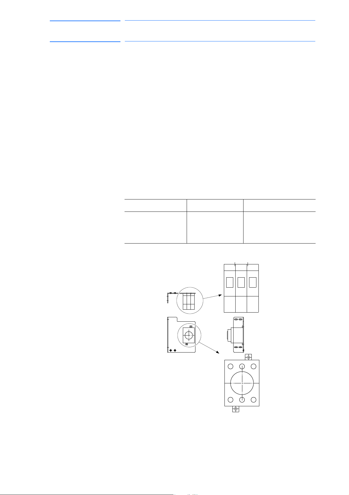
4.1 Creating a Check Program
To check position deviation whenever necessary, create a program in
which a check point is taught (the job for the check point). In the job for the
check point, teach two points; one as a check point and the other as the
point to approach the check point. This program checks for any deviation
between the tool tip position and the check point.
Fig. 4-1: <Enlarged View>
4-3
RE-CHO-A109
Page 36

DX100 European
WARNING
WARNING
36 of 764
Standard Maintenance
5 Replacing Parts
5.1 Replacing DX100 Parts
5Replacing Parts
5.1 Replacing DX100 Parts
• Turn OFF the power supply before opening the DX100 doors.
Failure to observe this warning may result in electric shock.
• After turning OFF the power supply, wait at least five minutes before
Failure to observe this warning may result in electric shock.
171768-1CD
replacing a SREVOPACK (including the converter) or CPS unit. Do
not touch any terminals during this period.
• To prevent anyone inadvertently turning ON the power supply
during maintenance, put up a warning sign such as “DO NOT TURN
ON THE POWER” at the primary power supply (knife switch, wiring
circuit breaker, etc.) and at the DX100 and related controllers and
use accepted lockout/tagout procedures.
Failure to observe this caution may result in electric shock or injury.
• Do not touch the regeneration resistors. They are very hot.
Failure to observe this caution may result in burn injuries.
• After maintenance is completed, carefully check that no tools are
left inside the DX100 and that the doors are securely closed.
Failure to observe this caution may result in electric shock or injury.
5-1
RE-CHO-A109
Page 37

171768-1CD
CPS Unit
CPU Unit
VUTSRQPNM
L
KJHGFEDC
BA
30
292827261425242322
21
20
19181716151312
11
10
0908070605040302
01
MADE IN JAPAN
Fuji Electric Hi-Tech Corp.
DATE
NO.
POWER SUPPLY
CPS-520F
VUTSRQPNM
L
KJHGFEDC
BA
30
292827261425242322
21
20
19181716151312
11
10
0908070605040302
01
CN154
(+24V1/+24V2)
CN158
(+5V)
CN155
(+24V1/+24V2)
(+24V2)
CN156/157
(+24V3)
CN153
(REMOTE)
CN152
SOURCE
OHT
INPUT
FAN
+24V
+5V
P-ON
50/60Hz
(AC IN)
CN151
200-240V AC
3.4A-2.8A
CN107
CN106
CN105
CN104
CN103
Ground connecting terminal
+24V1/+24V2 Power supply
output connector
(CN154/CN155)
+24V3 Power supply
output connector
(CN153)
(CN152)
+24V2 Power supply output connector
(CN156/CN157)
Connector 1 for connecting with CPU (CN158)
Connector 2 for connecting with CPU(CN159)
AC power supply
input connector
(CN151)
JANCD-YIF01- E
Robot I/F board
JANCD-YCP01-E
Control circuit board
Specified PCI slot for
sensor board X1
Battery
(CN113)
Drive I/F (communication with EAXA)
(CN114)
IO I/F (communication with YIU)
LED
(CN103)
Serial Port (RS232C)
(CN104)
For LAN
(CN106)
USB
(CN105)
For programming pendant
(CN107)
PCI Slot X2
Monitor, alarm display LED
Compact flash
Remote control connector
CN159
(ALM)
37 of 764
DX100 European
Standard Maintenance
5 Replacing Parts
5.1 Replacing DX100 Parts
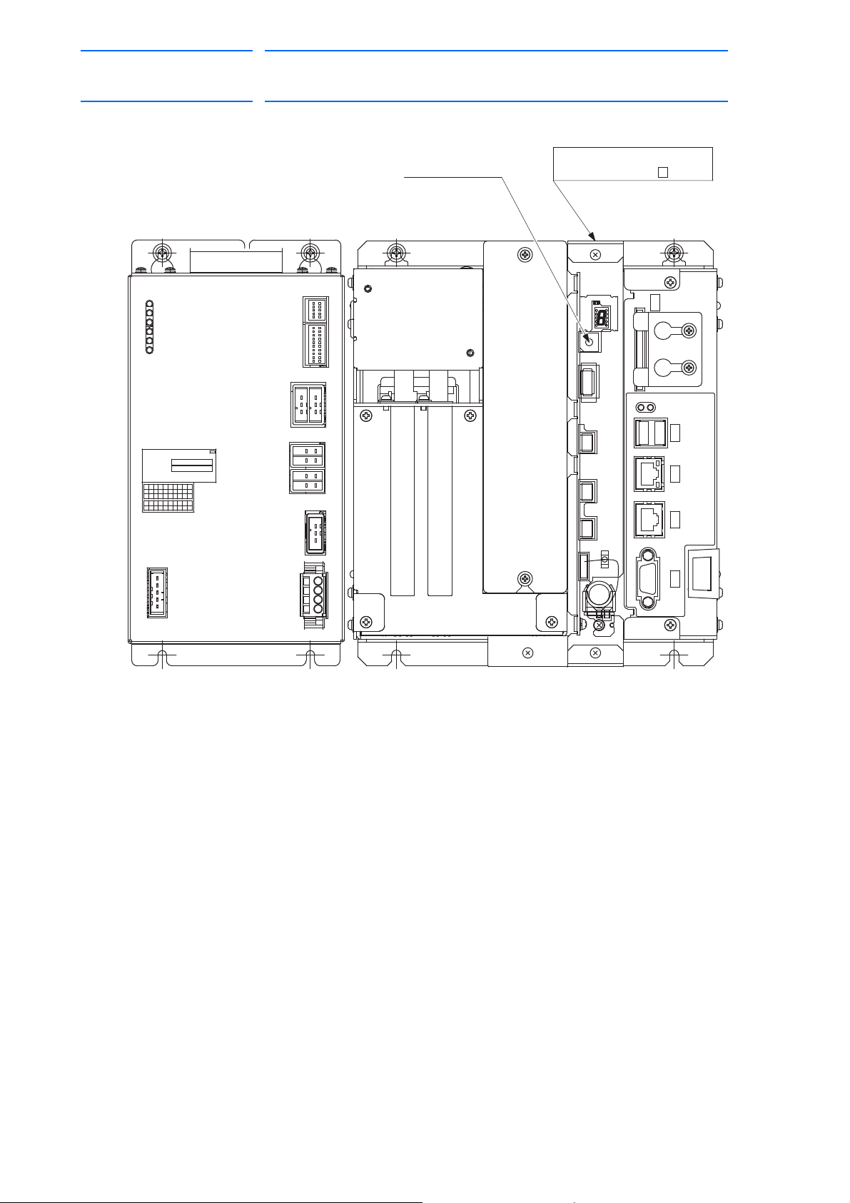
5.1.1 Replacing Parts of the CPU Unit
CPU unit (JZNC-YRK01-1E) is comprised of the rack for the various circuit
boards, control circuit board (JANCD-YCP01-E) and robot I/F board
(JANCD-YIF01-E). CPS unit (JZNC-YPS01-E) is a separated unit and it
is arranged to the left side of CPU unit.
Fig. 5-1: Configuration of CPU rack and CPS unit (JZNC-YRK01-1E,
JZNC-YPS01-E)
5-2
RE-CHO-A109
Page 38

DX100 European
NOTE
38 of 764
Standard Maintenance
5.1.1.1 Replacing the Battery
The battery must be replaced as soon as the message “Memory battery
weak” appears at the programming pendant display.
Replace the battery within two hours after the main power switch is turned
OFF.
Replacement Procedure
1. Loosen the screws on the battery connector holder and slide it to the
2. Remove the battery connector (CN110/BAT) on the robot I/F board
3. Mount a new battery on the robot I/F board and connect the connector
4. Slide the battery connector holder to the left and fix it with the screws.
5. Please confirm that the above mentioned message is not indicated at
171768-1CD
5 Replacing Parts
5.1 Replacing DX100 Parts
right.
(JANCD-YIF01-E) and loosen the fixing screws below the battery to
remove the battery.
110/BAT).
(CN
the
programming pendant display after battery replacement.
5.1.1.2 Replacing the Control Circ
Turn OFF the power before replacing a circuit board.
Replacement Procedure
1. Disconnect all cables connected to the circuit board.
2. Remove screws fixing the circuit board from upper and lower side.
(
one part at each side)
3. Pull out the circuit board from the rack.
4. Remove the Compact Flash from the removed circuit board and insert
the
Although the CMOS memory is backed up by a super
capacitor, the battery must be replaced as soon as the
message “Memory battery weak” appears.
The job data and other data may be lost if the message
“Memory battery weak” appears and the main power switch
is turned OFF for more than two hours.
uit Board (JANCD-YCP01-E)
Compact Flash into a new circuit board.
5. Mount the new circuit board to the rack.
6. Tighten upper and lower screws.
7. Connect all disconnected cables.
5-3
RE-CHO-A109
Page 39

171768-1CD
ABCDEFGHJK
LMNPQRSTUV
YYYY-MM
CPS-520F
POWER SUPPLY
NO.
DATE
Fuji Electric Hi-Tech Corp.
MADE IN JAPAN
C90AD XXXXX
010203040506070809 10
111213 151617181920
2122232425142627282930
ABCDEFGHJK
LMNPQRSTUV
(CN107)
Compact flash
JANCD-YCP01-E
Control circuit board
CN154
(+24V1/+24V2)
CN159
CN158
(+5V)
CN155
(+24V1/+24V2)
(+24V2)
CN156/157
(+24V3)
CN153
(REMOTE)
CN152
(ALM)
INPUT
50/60Hz
(AC IN)
CN151
200-240V AC
3.4A-2.8A
SOURCE
OHT
FAN
+24V
+5V
P-ON
CN103CN104CN105CN106
CN107
39 of 764
DX100 European
Standard Maintenance
5 Replacing Parts
5.1 Replacing DX100 Parts
5-4
RE-CHO-A109
Page 40

DX100 European
WARNING
ABCDEFGHJK
LMNPQRSTUV
YYYY-MM
CPS-520F
POWER SUPPLY
NO.
DATE
Fuji Electric Hi-Tech Corp.
MADE IN JAPAN
C90AD XXXXX
01020304050607080910
111213 151617181920
2122232425142627282930
ABCDEFGHJK
LMNPQRSTUV
CN154
(+24V1/+24V2)
CN159
CN158
(+5V)
CN155
(+24V1/+24V2)
(+24V2)
CN156/157
(+24V3)
CN153
(REMOTE)
CN152
(ALM)
INPUT
50/60Hz
(AC IN)
CN151
200-240V AC
3.4A-2.8A
SOURCE
OHT
FAN
+24V
+5V
P-ON
CN103CN104CN105CN106
CN107
JZNC-YPS01-E
CPS UNIT
40 of 764
Standard Maintenance
5 Replacing Parts
5.1 Replacing DX100 Parts
5.1.1.3 Replacing the CPS Unit (JZNC-YPS01-E)
• After turning OFF the power supply, wait at least five minutes before
replacing a control power supply. Do not touch any terminals during
this period. Confirm all monitor lights are turned OFF.
Failure to observe this caution may result in electric shock or injury.
Replacement Procedure
1. Disconnect all cables connected to the CPS unit.
2. Loosen the upper and lower side screws (four places) fixing the CPS
unit to the controller.
3. Hold the body of the CPS unit, then pull and remove the CPS unit from
the c
ontroller.
171768-1CD
4. Hook the new CPS unit to the screws (four places).
5. Tighten the upper and lower side screws (four places) to fix the CPS
un
it.
6. Connect all the disconnected cables.
5-5
RE-CHO-A109
Page 41

171768-1CD
NOTE
41 of 764
DX100 European
Standard Maintenance
5 Replacing Parts
5.1 Replacing DX100 Parts
5.1.1.4 Replacing the Robot I/F Board (JANCD-YIF01-
• Turn OFF the power before replacing the robot I/F
board.
• Be sure to back up robot data before replacing the robot
I/F board since the robot I/F board contains important
data such as robot jobs and parameters.
• There are some versions which require maker mode
operations after replacing the robot I/F board.
Contact your Yaskawa representative for maker mode
operations.
Replacement Procedure
1. Back up the robot data.
Insert a CF card for backup to the programming pendant, and start the
system in maintenance mode.
Select {EX.MEMORY} {SAVE} "CMOS" to save the CMOS data.
Backup all the individual data for safe.
E)
2. Turn OFF the power after making backup.
3. Disconnect all cables on the robot I/F board.
4. Remove two screws fixing the robot I/F board and rack.
5. Pull out the robot I/F board from the rack.
6. Insert new robot I/F board into the slot of the rack.
7. Tighten upper and lower screws of the robot I/F board.
8. Connect all the cables disconnected in step 3.
9. Set the rotary switch as the same value as the original I/F board.
10. Start up the system in maintenance mode and insert the CF card with
the ba
cked up data in procedure 1 to the programming pendant.
Change the mode from security mode to management mode. Select
{EX.MEMORY} {LOAD} "CMOS" to start loading the data. After
ading, the state returns to the state as before the replacement.
lo
5-6
RE-CHO-A109
Page 42
DX100 European
ABCDEFGHJK
LMNPQRSTUV
YYYY-MM
CPS-520F
POWER SUPPLY
NO.
DATE
Fuji Electric Hi-Tech Corp.
MADE IN JAPAN
C90AD XXXXX
010203040506070809 10
111213 151617181920
2122232425142627282930
ABCDEFGHJK
LMNPQRSTUV
Rotary switch
JANCD-YIF01- E
Robot I/F board
CN154
(+24V1/+24V2)
CN159
CN158
(+5V)
CN155
(+24V1/+24V2)
(+24V2)
CN156/157
(+24V3)
CN153
(REMOTE)
CN152
(ALM)
SOURCE
OHT
INPUT
FAN
+24V
+5V
P-ON
50/60Hz
(AC IN)
CN151
200-240V AC
3.4A-2.8A
CN103CN104CN105CN106
CN107
42 of 764
Standard Maintenance
171768-1CD
5 Replacing Parts
5.1 Replacing DX100 Parts
5-7
RE-CHO-A109
Page 43

171768-1CD
NOTE
43 of 764
DX100 European
Standard Maintenance
5 Replacing Parts
5.1 Replacing DX100 Parts
5.1.1.5 Replacing the I/O Unit (JZNC-YIU0
Turn OFF the power before replacing the I/O unit.
Replacement Procedure
1. Disconnect all the cables connected to the I/O unit.
(Disconnect the ground wire screwed to the front side of the unit.)
2. Loosen the upper screws (two places) fixing the I/O unit.
3. Hold and pull the I/O unit, then remove it from the controller.
4. Insert the lower part flange of the new I/O unit into the fixing jig, and
mo
unt it to the controller.
5. Tighten the upper side screws (two places) to fix the I/O unit.
6. Connect all the disconnected cables.
(Connect the ground wire firmly.)
7. If CN300 has a termination connector (CBL-YRC020), install it at the
right of
CN300 in the new I/O unit.
2-E)
8. Set the rotary switch to the same value as the removed unit’s rotary
sw
itch.
5-8
RE-CHO-A109
Page 44

DX100 European
3.15
F1, F2
(CN301)
(CN303)
(CN304)
(CN309)
Digital I/O connector
Digital I/O connector
(CN300)
(CN302)
(CN305)
D1:24V2IN LED
(CN306)
(CN307)
Digital I/O connector
(CN308)
Digital I/O connector
Communication switch
Rotary switch
D2:FUSE CUT LED
Panel IO connector
Universal input connector
Power supply protective
fuse 3.15 A/250 V
For switching external
power supply
Power supply output connector
Power supply input connector
Fixing jig for the flange
44 of 764
Standard Maintenance
171768-1CD
5 Replacing Parts
5.1 Replacing DX100 Parts
Fig. 5-2: I/O Unit JZNC-YIU02-E
5-9
RE-CHO-A109
Page 45
171768-1CD
NOTE
A01
2FU FU
A01
1
CN601
SVMX2SVMX1
CN606
CN612
CN608
CN602
CN603
CN604
CN605
3FU 2.5A
4FU 2.5A
SVMX2
SVMX1
CN603
CN604
CN605
CN612
CN606
NCM
CN607
CN611
3FU4FU
1FU2FU
CN610
CN601
CN609CN608
CN602
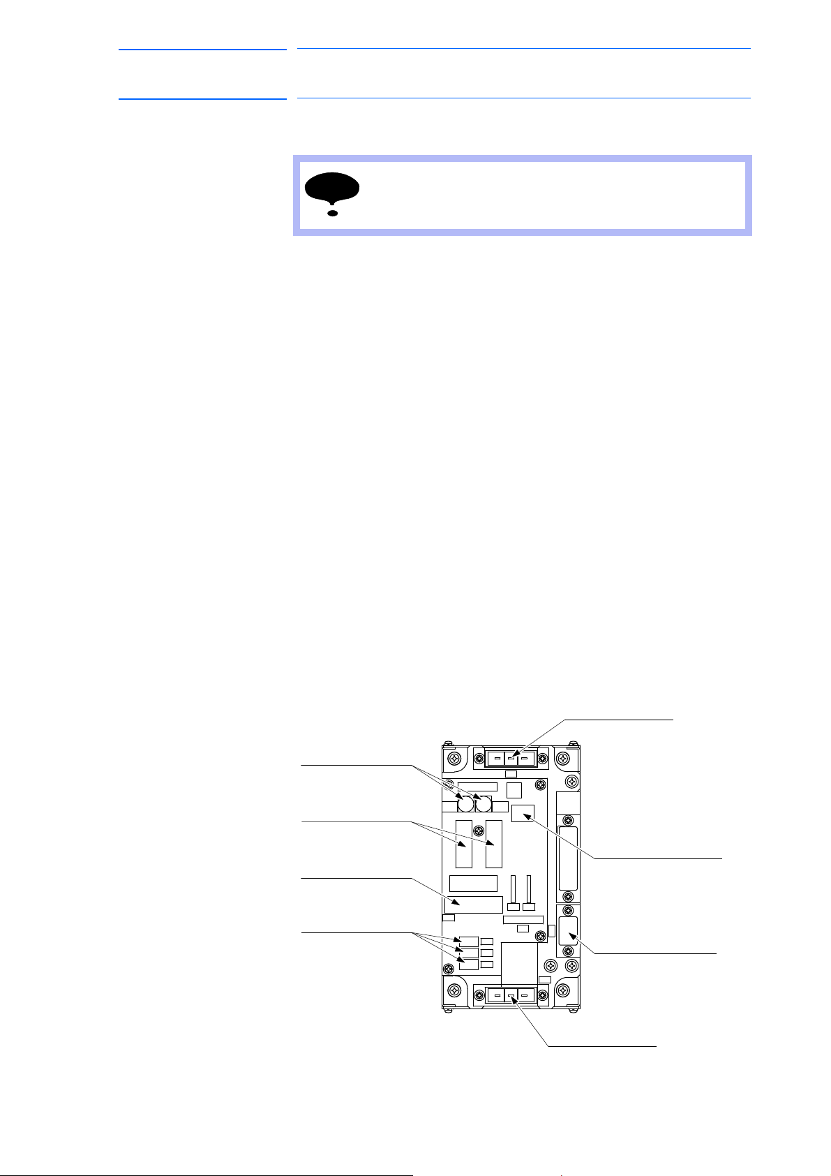
(CN608)
(CN607)
Main power input connectors
Converter output connectors
AC control power supply
connectors
AC cooling fan connectors
GP25(2.5A 250V)
Fuse for AC cooling fan
(4FU),(3FU)
0218010P(10A 250V)
AC control power supply fuse
Brake interlock output connectors
Contactor control input connectors
(CN602)
(2FU),(1FU)
(CN606)
(CN605,CN604,CN603)
(CN601)
45 of 764
DX100 European
Standard Maintenance
5 Replacing Parts
5.1 Replacing DX100 Parts
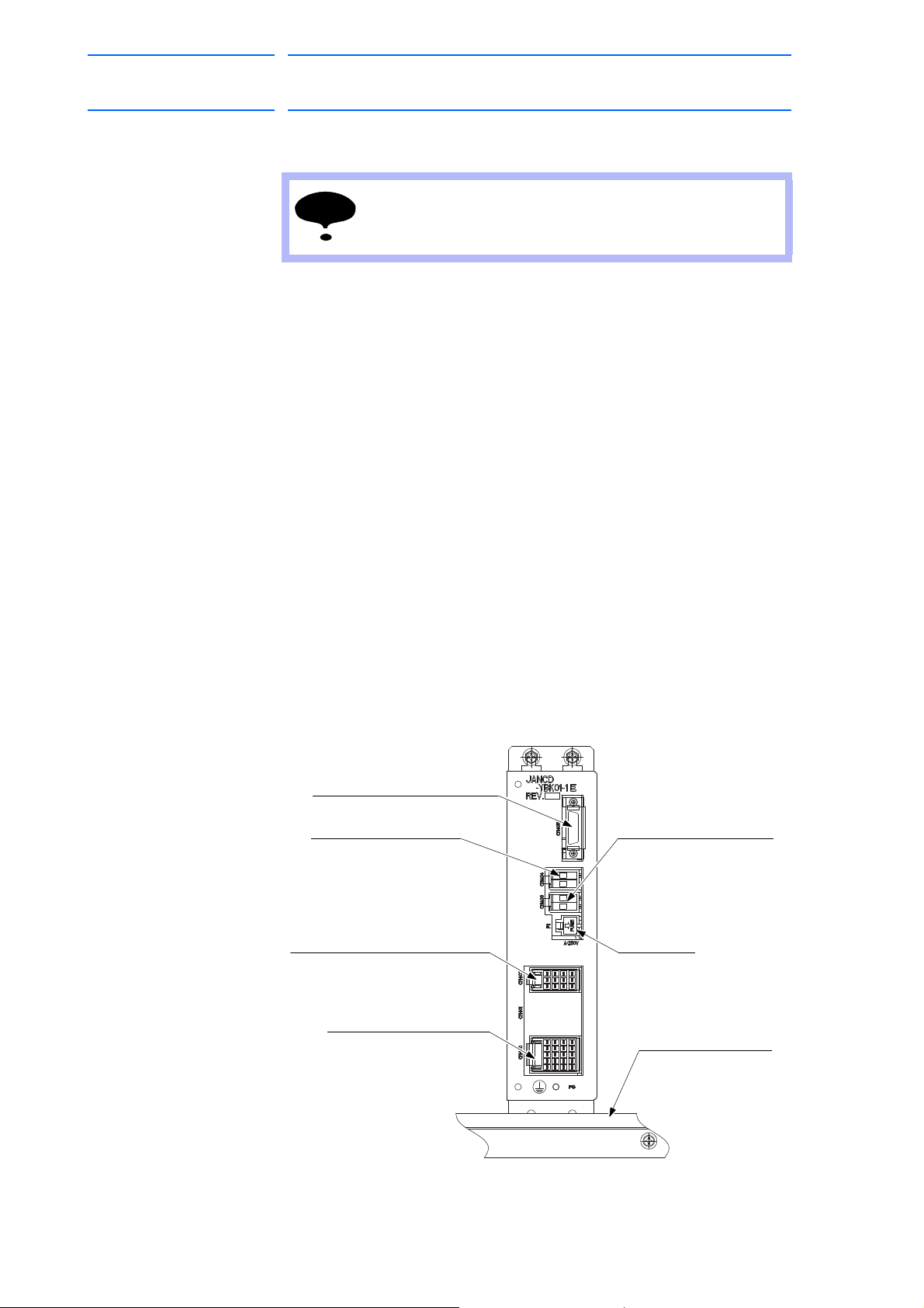
5.1.1.6 Replacing the Power Supply Contactor Unit (JZRCR-YPU01-
Turn OFF the power before replacing the unit.
Replacement Procedure
1. Disconnect all the cables connected to the power supply contactor
unit.
*The following connectors are not necessarily disconnected since they
are to connected inside the unit.
CN610, CN611, CN612
(Disconnect the ground wire screwed to the front side of the unit.)
2. Loosen upper and lower side screws (four places) fixing the power
supply contactor unit to the controller.
3. Hold and pull the power supply contactor unit, then remove it from the
contr
oller.
*Do not hold the board only, but hold it together with the unit because it
may cause damage to the board or personal injury.
)
4. Hook the new power supply contactor unit to the screws in the
contr
oller (4 places).
*Do not hold the board only, but hold it together with the unit because it
may cause damage to the board or personal injury.
5. Tighten the upper and lower side screws (four
power supply contactor unit.
6. Connect all the disconnected cables.
(Connect the ground wire firmly.)
Fig. 5-3: Configuration of Power Supply Contactor Unit (JZRCR-YPU01-1)
places) firmly to fix the
5-10
RE-CHO-A109
Page 46
DX100 European
NOTE
3.15
F1: Fuse
3.15 A/250 V
(CN405)
Brake command input connector
(CN404)
Connector for switching
the external power supply
(CN403)
Connector for brake power
supply input
Brake output connector
(CN400)
(CN402)
Contactor interlock input connector
Fixing jig for the flange
46 of 764
Standard Maintenance
5 Replacing Parts
5.1 Replacing DX100 Parts
5.1.1.7 Replacing the Brake Control Board (JANCD-YBK01-1E)
Turn OFF the power before replacing the unit.
Replacement Procedure
1. Disconnect the cable connectors connected to the brake control board.
*Do not disconnect jumper wiring connectors at CN404 yet.
(Disconnect the ground wire screwed to the front side of the board.)
2. Loosen the upper side screws (two places) fixing the brake control
board to the controller.
3. Hold and pull the brake control board, and remove it from the
controll
4. Insert the lower part flange of the new brake control board into the
fixing
er.
jig, and mount it to the controller.
171768-1CD
5. Tighten the upper side screws (two
places) to fix the brake control
board.
6. Disconnect CN404 jumper wiring conn
ectors from the removed brake
control board and connect them to CN404 on the new brake control
board.
7. Connect all the disconnected cables.
(Connect the ground wire firmly.)
Fig. 5-4: Brake Control Board (JANCD-YBK01-1E)
5-11
RE-CHO-A109
Page 47

171768-1CD
NOTE
47 of 764
DX100 European
Standard Maintenance
5.1.1.8 Replacing the Machine Safety Unit (JZNC-YSU01-1E)
5 Replacing Parts
5.1 Replacing DX100 Parts
Turn OFF the power before replacing the unit.
Replacement Procedure
1. Disconnect all the cables connected to the machine safety unit.
*Do not disconnect the terminating connectors (CBL-YRC020) at
CN202 yet.
(Disconnect the ground wire screwed to the front side of the unit.)
2. Loosen the upper side screws (two places) fixing the machine safety
unit to the controller.
3. Hold and pull the machine safety unit, and remove it from the
contr
oller.
4. Insert the lower part flange of the new machine safety unit into the
fix
ing jig, and mount it to the controller.
5. Tighten the upper side screws (two places) to fix the machine safety
un
it.
6. Disconnect CN202 terminating connectors from the removed machine
safety
unit and connect them to the right side of CN202 on the new
machine safety unit.
7. Connect all the disconnected cables.
(Connect the ground wire firmly.)
8. Set the rotary switch to the same value as the removed unit’s rotary
itch.
sw
5-12
RE-CHO-A109
Page 48

DX100 European
FUSE
CN215 CN216
CN208
CN209
CN210
CN211
CN212 CN213 CN214
CN200 CN201
CN202
CN203 CN205 CN206 CN207
A
B
1
A
B
1
A
B
1
(CN208)
Emergency stop button for the door
(CN209)
PP I/F
(CN215)
For connector 3 and 4 systems
(CN210)
(CN211)
ONEN, EXONEN, EXOT
(CN216)
-X18 connection
(CN212)
FANALM, FANCTL, LAMP
(CN213)
Contactor control 2
(CN214)
I/F between AXA board
Contactor control 1
(CN202)
(CN203)
(CN200)
(CN201)
(CN205)
(CN206)
(CN207)
I/F between AXA board
-Communication
I/F between machine
safety units
F1, F2: Fuse
3.15 A/250 V
OT input connector
Power supply input
connector
Connector for power
supply output
I/F- IN
I/F- OUT
Fixing jig for the flange
48 of 764
Standard Maintenance
171768-1CD
5 Replacing Parts
5.1 Replacing DX100 Parts
Fig. 5-5: Machine Safety Unit (JZNC-YSU01-1E)
5-13
RE-CHO-A109
Page 49

171768-1CD
WARNING
49 of 764
DX100 European
Standard Maintenance
5 Replacing Parts
5.1 Replacing DX100 Parts
5.1.2 Replacing the SERVOPACK
• After turning OFF the power supply, wait at least five minutes before
replacing a SERVOPACK. Do not touch any terminals during this
period.
Failure to observe this warning may result in electric shock.
There are two kinds of SERVOPACKs.
Type Manipulator
Integrated Type MH5, MH5L, MH6, MA1400, MA1900, HP20D, HP20D-6,
HP20RD
Separated Type MH50, MH50-20, MH50-35, MS80, VS50, MA1800,
ES165D, ES165RD, ES200D, ES200RD, SIA50D,
HP165D, UP350D
Replacement Procedure
1. Turn OFF the main power switch and wait at least five minutes before
replacement Do not touch any terminals during this period.
2. Verify that the SERVOPACK charge lamp (red LED) is unlit.
3. Disconnect all the cables connected externally to the SERVOPACK.
(1) Converter control signal connector (CN553)
(2)
DC Control power supply connector (CN551)
(3) Safety unit I/F connector (CN511)
(4) Brake control signal connector (CN513)
(5) Control power supply input connector (CN509)
(6) SHOCK signal input connector (CN512)
(7) Ground terminal (EAXA base)
(8) Control communication connector (CN515)
(9) I/O communication connector (CN517)
(10) Encoder signal connector (CN508)
4. Put the disconnected cable to the left side of the SERVOPACK.
5. Unscrew two EAXA base fixing screws. (lower side)
6. Unscrew two EAXA base fixing screws. (upper
7. Open the EAXA base.
8. Disconnect all the cables from the amplifier to be replaced.
side)
5-14
RE-CHO-A109
Page 50

DX100 European
50 of 764
Standard Maintenance
171768-1CD
5 Replacing Parts
5.1 Replacing DX100 Parts
9. Remove screws fixing the amplifier.
*03 to 21 amplifier: Remove upper right and lower left screws
(2 places).
*35 to 71 amplifier: Remove IPM fixing screws (2 places) besides the
screws on the four corners (4 places).
10. Mount thermal sheet to the new amplifier.
(Refer to Thermal Sheet Mounting Instruction.)
11. Mount the new amplifier.
12. Connect all the disconnected cables to the new amplifier.
13. Tighten two EAXA base fixing screws. (upper side)
14. Tighten two EAXA base fixing screws. (low
15. Connect all the disconnected cables to the servopack.
er side)
5-15
RE-CHO-A109
Page 51

171768-1CD
EAXA board (-AE6)
Converter (-TP1)
AMP2 PWM signal connector
(CN502)
(CN501)
AMP1 PWM signal connector
AMP3 PWM signal connector
(CN503)
AMP4 PWM signal connector
(CN504)
AMP6 PWM signal connector
AMP5 PWM signal connector
(CN505)
(CN506)
EAXA base
EAXA base fixing
screw (bottom)
(CN516)
(CN518)
SHOCK signal input
connector
(CN512)
Control power supply
output connector for
converter
(CN510)
(CN513)
Connector for brake
control signal
Main circuit power supply output
connector for external axis amplifier
Upper grip
Ground terminal
Charge lamp
Monitor / Alarm
displaying LED
DC control power supply connector
(CN551)
(CN552A)
(CN552B)
Ground terminal
Lower grip
(CN507)
Connector for converter
control signal
(CN511)
Safety unit I/F connector
(CN514)
Direct-in connector
(CN517)
Control communication
connector
(CN515)
(CN508)
Connector for encoder
signal
(CN509)
Connector for control
power supply input
(CN556)
(CN558)
Connector for connecting
regenerative resistor
Connector for main
circuit power supply input
(CN557)
(CN555)
Connector for
grounding detection input
Connector for converter
control signal
(CN554)
(CN553)
Control communication
connector
I/O communication
connector
Control communication
connector
EAXA base fixing
screw (upper)
Control power supply
output connector for
6-axis amplifier
EAXA base fixing
screw (upper)
Main circuit power supply output
connector for 6-axis amplifier
Control power supply output
connector for external axis amplifier
51 of 764
DX100 European
Standard Maintenance
Fig. 5-6: SERVOPACK
5 Replacing Parts
5.1 Replacing DX100 Parts
5-16
RE-CHO-A109
Page 52

DX100 European
Control power supply input connectors
Control power supply input connectors
Control power supply input connectors
(CN582)
(CN583)
(CN581)
(CN584)
AMP4
(-TA4)
(CN582)
(CN583)
(CN581)
(CN584)
AMP6
(-TA6)
(CN582)
Control power supply input connectors
(CN583)
Main circuit power supply input connectors
(CN581)
(CN584)
AMP2
(-TA2)
(CN582)
(CN583)
(CN581)
(CN584)
AMP5
(-TA5)
(CN582)
(CN583)
(CN581)
(CN584)
AMP3
(-TA3)
(CN582)
(CN583)
Lower grip
(CN581)
(CN584)
AMP1
(-TA1)
Output connectors for motor power
PWM signal connectors
Output connectors for motor power
PWM signal connectors
Output connectors for motor power
PWM signal connectors
Output connectors for motor power
Output connectors for motor power
Output connectors for motor power
PWM signal connectors
PWM signal connectors
PWM signal connectors
Main circuit power supply input connectors
Main circuit power supply input connectors
Main circuit power supply input connectors
Main circuit power supply input connectors
Main circuit power supply input connectors
Control power supply input connectors
Control power supply input connectors
35 and 71 Amplifier
03 to 21 Amplifier
Amplifier fixing screw
Amplifier fixing screw
Amplifier fixing screw
Amplifier fixing screw
IPM fixing screw
52 of 764
Standard Maintenance
5 Replacing Parts
5.1 Replacing DX100 Parts
Fig. 5-7: Inside the EAXA Base
171768-1CD
Fig. 5-8: Amplifier/IPM Fixing Screw
5-17
RE-CHO-A109
Page 53

171768-1CD
"Thermal sheet mounting instruction"
SRDA-SDA71A01A-E
SRDA-SDA21A01A-E
SRDA-SDA35A01A-E toSRDA-SDA03A01A-E to
Thermal sheet: 400-007-165-01Thermal sheet: 400-007-166-01
Groove of the IPM
Details of groove part on IPM
Grooves
External axis amplifier: SRDA-SDA35A01A-E to SRDA-SDA71A01A-E
True up the edges of the IPM frame and its grooves that are at the bottom
of the amplifier, then affix the thermal sheet along the edge.
External axis amplifier: SRDA-SDA03A01A-E to SRDA-SDA21A01A-E
Affix the thermal sheet to the bottom of the amplifier along its grooves.
Affix the thermal sheet to the bottom of the amplifier along the grooves.
Edge of the
thermal sheet
Thermal sheet
Bottom of the amplifier
Thermal sheet
Bottom of the amplifier
Groove of the IPM
53 of 764
DX100 European
Standard Maintenance
5 Replacing Parts
5.1 Replacing DX100 Parts
Fig. 5-9: Thermal Sheet Mounting Instruction
5.1.3 Replacing the Converter
Type Manipulator
Integrated Type MH5, MH5L, MH6, MA1400, MA1900, HP20D, HP20D-6,
Separated Type MH50, MH50-20, MH50-35, MS80, VS50, MA1800,
Replacement Procedure (Integrated Type)
• How to Replace Converter
1. Turn OFF the main power switch and wait at least five minutes before
replacement. Do not touch any terminals during this period.
2. Verify that the converter charge lamp (red LED) is unlit.
3. Disconnect the cables connected externally to the converter and the
SER
(1) Ground fault detection input connector (CN554)
(2) Converter control signal connector (CN553)
HP20RD
ES165D, ES165RD, ES200D, ES200RD, SIA50D,
HP165D, UP350D
VOPACK.
(3) DC Control power supply connector (CN551)
(4) Control power supply output connector for 6-axis amplifier
(CN552A)
5-18
RE-CHO-A109
Page 54

DX100 European
54 of 764
Standard Maintenance
5 Replacing Parts
5.1 Replacing DX100 Parts
(5) Safety unit I/F connector (CN551)
(6) Brake control signal connector (CN513)
(7) Control power supply input connector (CN509)
(8) SHOCK signal input connector (CN512)
(9) Ground terminal (EAXA base)
(10) Control communication connector (CN515)
(11) I/O communication connector (CN517)
(12) Encoder signal connector (CN508)
4. Put the disconnected cable to the left side of the SERVOPACK.
5. Unscrew two EAXA base fixing screws. (lower side)
6. Unscrew two EAXA base fixing screws. (upper side)
7. Open the EAXA base.
8. Disconnect the other cables connected to the converter to be
r
eplaced.
171768-1CD
(1) Main circuit power supply input connector (CN555)
(
2) Regenerative resistor connecting connector (CN557)
(3) Main circuit power supply output connector for 6-axis amplifier
(CN556)
Remove the following only when wired:
(4) Control power supply output connector for external axis amplifier
(CN552B)
(5) Main circuit power supply output connector for external axis ampli-
fier (CN558)
9. Remove the ground wiring connected to the converter.
10. Remove 4 screws fixing the converter.
11. Hold the top grip and lift it to pull out the converter.
12. Install the new converter and reconnect the connectors in the reverse
or
der of the removing procedure.
(Connect the ground wire firmly.)
5-19
RE-CHO-A109
Page 55

171768-1CD
Connector for connecting
regenerative resistor
EAXA base fixing
screw (upper)
Connector for converter
control signal
Connector for
grounding detection input
Ground terminal
Connector for main
circuit power supply input
EAXA base fixing
screw (upper)
SHOCK signal input
connector
Connector for control
power supply input
Connector for encoder
signal
I/O communication
connector
I/O communication
connector
Control communication
connector
Control communication
connector
EAXA base
EAXA base fixing
screw (bottom)
(CN513)
(CN507)
(CN511)
(CN514)
AMP2 PWM Signal connector
(CN502)
(CN501)
AMP1 PWM Signal connector
AMP3 PWM Signal connector
(CN503)
AMP4 PWM Signal connector
(CN504)
AMP6 PWM Signal connector
AMP5 PWM Signal connector
(CN505)
(CN506)
EAXA Board (-AE6)
(CN552B)
Converter (-TP1)
(CN556)
(CN558)
(CN516)
(CN518)
(CN512)
Grounding terminal
(CN517)
(CN515)
(CN508)
(CN509)
(CN551)
(CN552A)
(CN557)
(CN555)
(CN554)
(CN553)
Connector for converter
control signal
Direct-in connector
Safety unit I/F connector
Connector for break
control signal
Charge lamp
Main circuit power supply output
connector for external axis amplifier
Main circuit power supply output
connector for 6-axis amplifier
Control power supply output
connector for external axis amplifier
DC control power
supply connector
Control power supply
output connector for
6-axis amplifier
Monitor/Alarm
displaying LED
55 of 764
DX100 European
Standard Maintenance
5 Replacing Parts
5.1 Replacing DX100 Parts
Fig. 5-10: Integrated SERVOPACK
5-20
RE-CHO-A109
Page 56

DX100 European
Converter (-TP1)
(CN551)
(CN552A)
(CN552B)
(CN556)
(CN558)
(CN557)
(CN555)
(CN554)
(CN553)
DC control power
supply connector
Control power supply output
connector for 6-axis amplifier
Control power supply
output connector for external
axis amplifier
Main circuit power supply output
connector for 6-axis amplifier
Charge lamp
Main circuit power supply
output connector for external
axis amplifier
Connector for main
circuit power supply input
Connectorfor connecting
regenerative resistor
Ground terminal
Connector for
grounding detection input
Connector for converter
control signal
Monitor / Alarm
displaying LED
56 of 764
Standard Maintenance
171768-1CD
5 Replacing Parts
5.1 Replacing DX100 Parts
Replacement Procedure (Separated Type)
• How to Replace Converter
1. Turn OFF the main power switch and wait at least five minutes before
replacement. Do not touch any terminals during this period.
2. Verify that the converter charge lamp (red LED) is unlit.
3. Disconnect all the cables connecte
d externally to the converter.
(1) Ground fault detection input connector (CN554)
(
2) Converter control signal connector (CN553)
(3) DC control power supply connector (CN551)
(4) Main circuit power supply input connector (CN555)
(5) Regenerative resistor connecting connector (CN557)
(6) Main circuit power supply output connector for 6-axis amplifier
(CN556)
(7) Control power supply output connector for 6-axis amplifier
(CN552A)
Disconnect the following connectors when they are connected.
(8) Control power supply connector for external axis amplifier
(CN552B)
(9) Main circuit power supply output connector for external axis
amplifier (CN558)
4. Remove the ground wiring connected to the converter.
5. Remove the screws fixing the converter. (four places)
6. Hold the top grip and lift it to pull out the converter.
Fig. 5-11: Separated Type Converter
7. Install the new converter and reconnect the connectors in the reverse
or
der of the removing procedure.
(Connect the ground wire firmly.)
5-21
RE-CHO-A109
Page 57
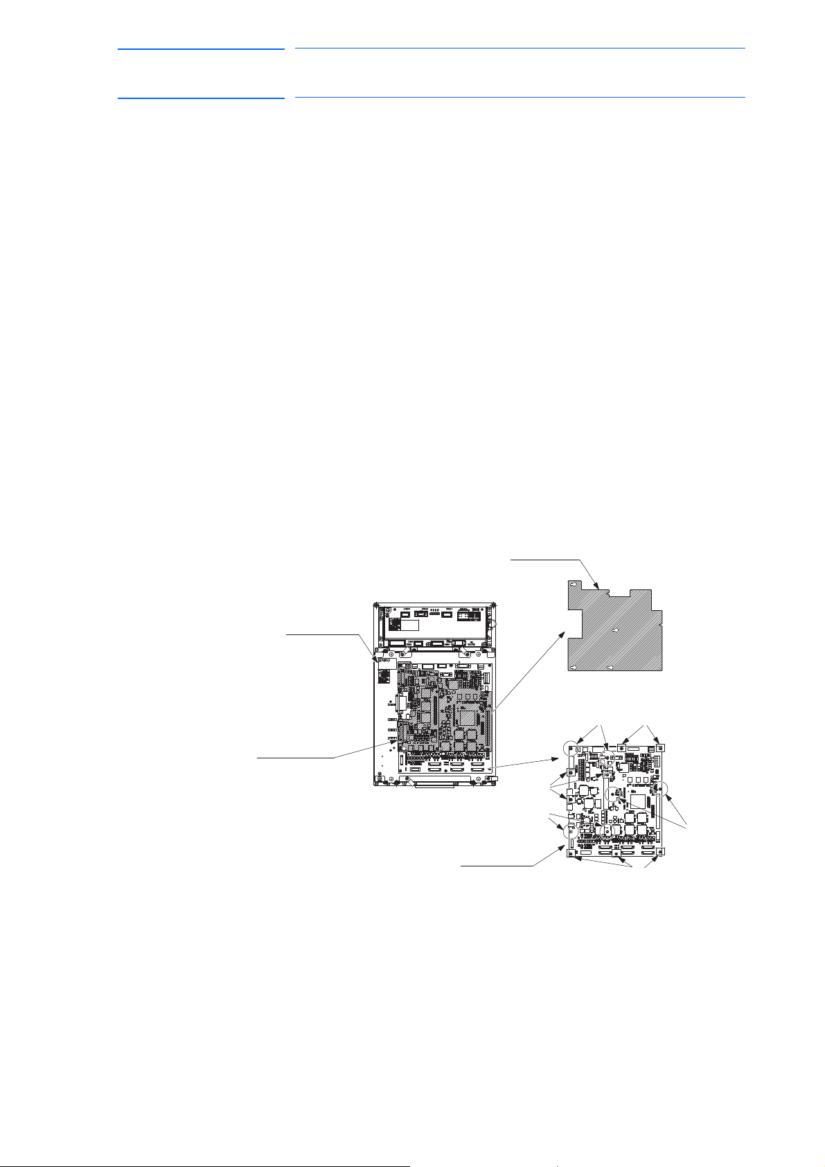
171768-1CD
EAXA Board
B ScrewA Screw
EAXA Cover
SERVOPACK
EAXA Cover
A Screw
A Screw
B Screw
B Screw
57 of 764
DX100 European
Standard Maintenance
5 Replacing Parts
5.1 Replacing DX100 Parts
5.1.4 Replacing the Major Axes Control Circuit Board (SRDA-EAXA01A)
Turn OFF the power before replacing the circuit board.
Replacement Procedure
1. Disconnect all the cables connected to the circuit board.
2. Remove A screws. (six places)
3. Remove the EAXA cover.
4. Remove hexagon threaded spacers (six places) fixing A screws.
5. Remove B screws (eight places).
6. Remove the control circuit board from the SERVOPACK.
7. Install the new circuit board to the SERVOPACK in the reverse order of
the r
emoving procedure.
8. Set the rotary switch to the same value as the removed circuit board’s
rot
ary switch.
9. Reinstall the EAXA cover.
10. Connect all the disconnected cables in step 1.
Fig. 5-12: Major Axes Control Circuit Board Replacement Procedure
5-22
RE-CHO-A109
Page 58
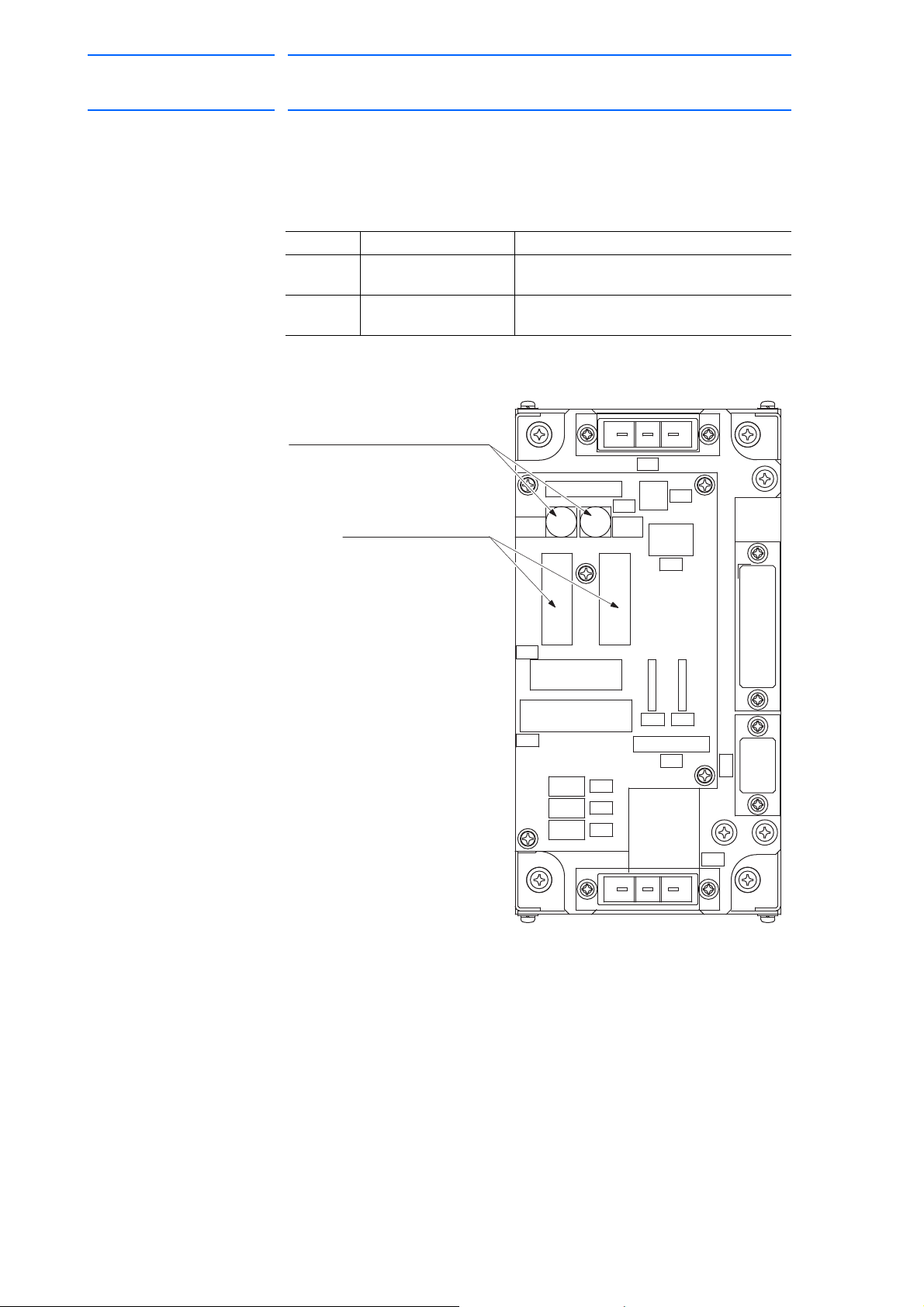
DX100 European
A01
2FU FU
A01
1
CN601
CN610
CN611
CN607
SVMX2SVMX1
CN601
CN606
CN612
CN608
CN602
CN603
CN604
CN605
SVMX2SVMX1
3FU 2.5A
4FU 2.5A
GP25(2.5A 250V)
(4FU), (3FU)
0218010P(10A 250V)
Fuse for AC control power supply
(2FU), (1FU)
SVMX2
SVMX1
CN603
CN604
CN605
CN612
CN606
NCM
CN607
CN611
3FU4FU
1FU2FU
CN610
CN601
CN609CN608
CN602
Fuse for cooling fan
58 of 764
Standard Maintenance
5 Replacing Parts
5.1 Replacing DX100 Parts
5.1.5 Checking and Replacing Fuses
5.1.5.1 Power Supply Contactor Unit
The types of fuses on power supply contactor unit (JZRCR-YPU01-) are
as follows:
Parts No. Fuse Name Specification
1FU, 2FU AC Control Power
3FU,4FU AC Cooling Fan Fuse GP25, 2.5 A, 250V
Fig. 5-13: Replacement Fuse of the Power Supply Contactor Unit
Supply Fuse
171768-1CD
0218010P
250V,10A, Time Lag Fuse (Littelfuse, Inc.)
(Daito Communication Apparatus Co., Ltd.)
If the fuse is blown, replace it with the same type of fuse (supplied or
spare parts).
5-23
RE-CHO-A109
Page 59

171768-1CD
F1, F2
24 VDC fuse for I/O
59 of 764
DX100 European
Standard Maintenance
5.1.5.2 I/O Unit
5 Replacing Parts
5.1 Replacing DX100 Parts
The types of fuses on the I/O unit (JZNC-YIU02-E) are as follows:
Parts No. Fuse Name Specification
F1, F2 24 V
Fuse for I/O 02173.15P, 250 V,3.15 A,
DC
Fast-acting Fuse (Littelfuse, Inc.)
Fig. 5-14: Replacement Fuse of I/O Unit (JZNC-YIU02-E)
If the fuse is blown, replace it with the same type of fuse (supplied or
spare parts).
5-24
RE-CHO-A109
Page 60
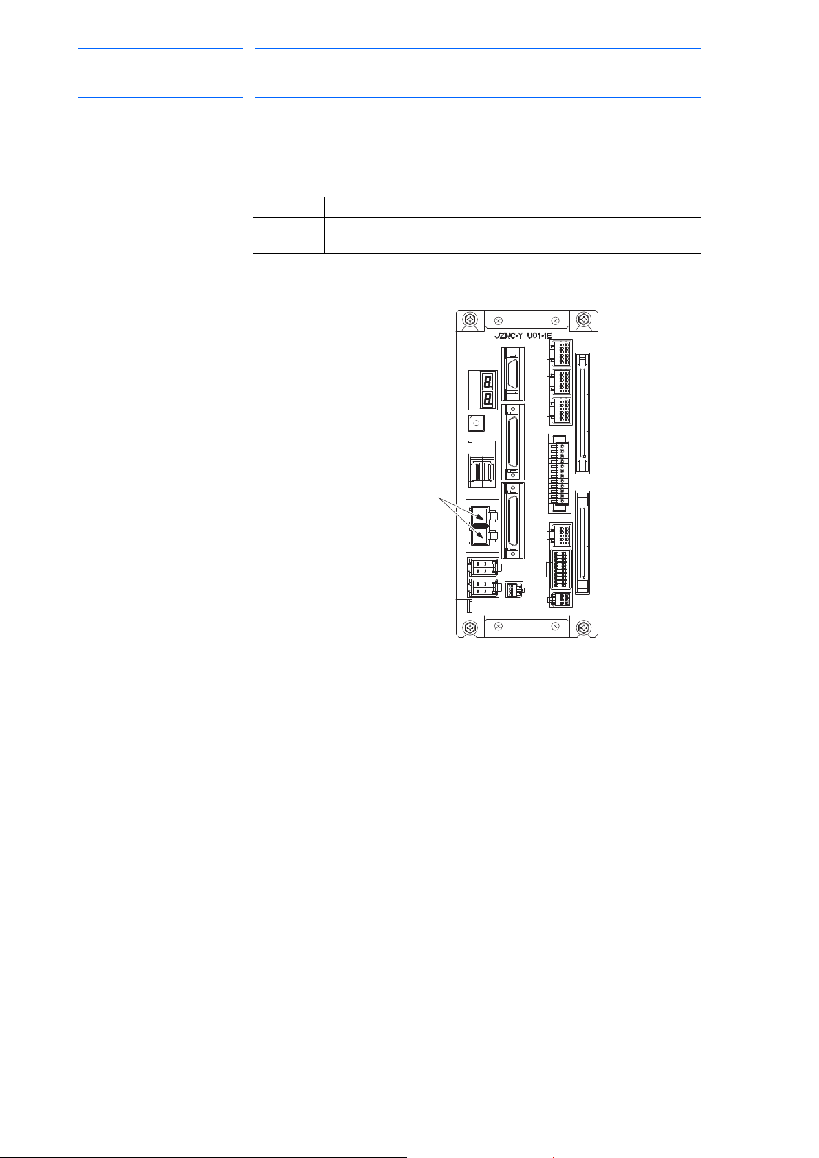
DX100 European
FUSE
CN215 CN216
CN208
CN209
CN210
CN211
CN212 CN213 CN214
CN200 CN201
CN202
CN203 CN205 CN206 CN207
A
B
1
A
B
1
A
B
1
F1, F2
24 VDC Fuse for I/O
FRC5-C50S52T-OLS(D20)
s
60 of 764
Standard Maintenance
5.1.5.3 Machine Safety Unit
171768-1CD
5 Replacing Parts
5.1 Replacing DX100 Parts
The types of fuses on the machine safety unit (JZNC-YSU01-1E) are as
follows.
Parts No. Fuse Name Specification
F1, F2 24 V
Fuse for I/O 02173.15P, 250 V, 3.15 A,
DC
Fast-acting Fuse (Littelfuse, Inc.)
Fig. 5-15: Replacement Fuse of Machine Safety Unit (JZNC-YSU01-1E)
If the fuse is blown, replace it with the same type of fuse (supplied or
spare parts).
5-25
RE-CHO-A109
Page 61
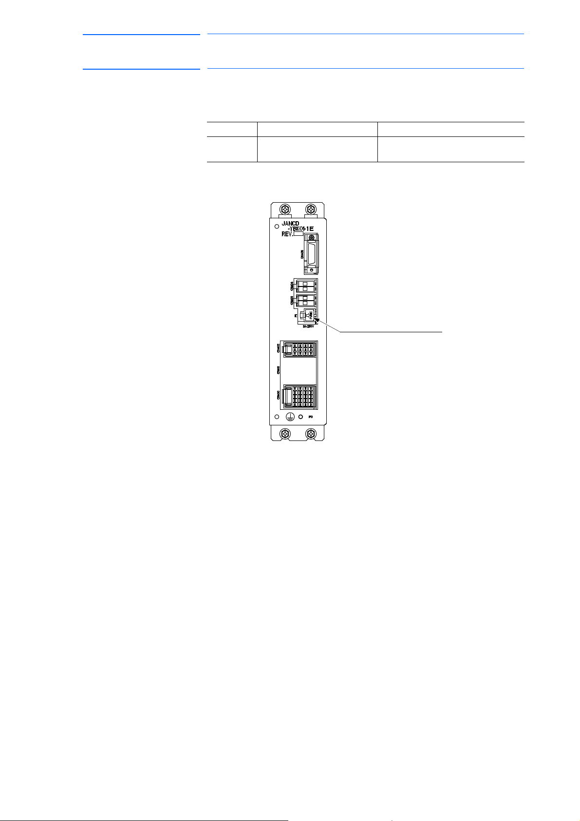
171768-1CD
F1: Brake power supply fuse
for external axis
61 of 764
DX100 European
Standard Maintenance
5.1.5.4 Brake Control Board
5 Replacing Parts
5.1 Replacing DX100 Parts
The types of fuses on the brake control board (JANCD-YBK01-1E) are as
follows:
Parts No. Fuse Name Specification
F1 Brake Power Supply Fuse for
External Axis
02173.15P, 250 V, 3.15 A,
Fast-acting Fuse (Littelfuse, Inc.)
Fig. 5-16: Replacement Fuse of Brake Control Board (JANCD-YBK01-1E)
If the fuse is blown, replace it with the same type of fuse (supplied or
spare parts).
5-26
RE-CHO-A109
Page 62
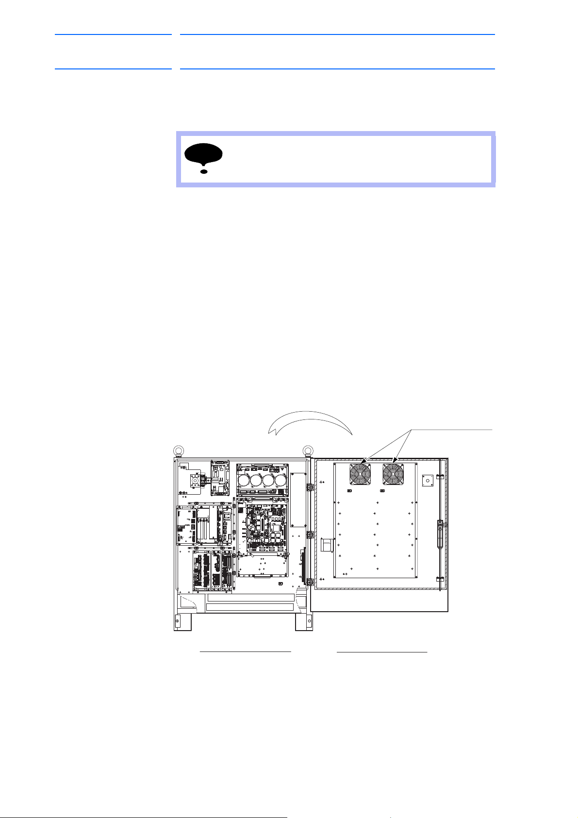
DX100 European
NOTE
4715MS-22T-B5A-B00
Interior circulation fan:
(For air inlet)
Inside View of Door
Front View
Inside the Controller
62 of 764
Standard Maintenance
5 Replacing Parts
5.1 Replacing DX100 Parts
5.1.6 Interior Circulation Fan
5.1.6.1 Replacing the Interior Circulation Fan
Turn OFF the power before replacing the fan.
Replacement Procedures
1. Open the door.
2. Disconnect plug cables connected to the fan.
(Remove the ground wire screwed to the fan.)
3. Remove the screws (two places) fixing the fan.
4. Uninstall the fan from the controller.
171768-1CD
5. Install the new fan to the controller.
6. Tighten the screws (two places) to fix the fan.
7. Connect all the disconnected cables.
8. Close the door.
Fig. 5-17: Replacement of Interior Circulation Fan
5-27
RE-CHO-A109
Page 63
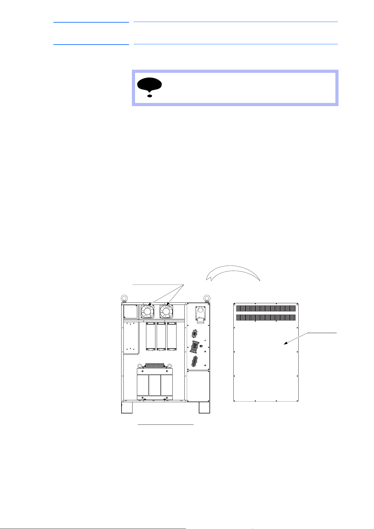
171768-1CD
NOTE
4715MS-22T-B5A-B00
(For air inlet)
Interior circulation fan:
Backboard
(without backboard)
Back View
63 of 764
DX100 European
Standard Maintenance
5 Replacing Parts
5.1 Replacing DX100 Parts
5.1.6.2 Replacing the Backside Duct Fan
Replacement Procedures
1. Remove the backboard.
2. Disconnect plug cables connected to the fan.
(Remove the ground wire scr
3. Remove the screws (two places) fixing the fan.
Turn OFF the power before replacing the fan.
ewed to the fan.)
4. Uninstall the fan f
5. Install the new fan to
rom the controller.
the controller.
6. Tighten the screws (two places) to fix the fan.
7. Connect all the disconnected cables.
8. Mount the backboard.
Fig. 5-18: Replacement of Backside Duct Fan
5-28
RE-CHO-A109
Page 64

DX100 European
64 of 764
Standard Maintenance
5 Replacing Parts
5.2 DX100 Parts List
5.2 DX100 Parts List
Table 5-1: DX100 Parts List
No. Name Model Comment
1 SERVOPACK
2 CPU unit JZNC-YRK01-1E
Control circuit board JANCD-YCP01-E
3 Robot I/F board JANCD-YIF01-1E
4 CPS unit JZNC-YPS01-E
5 Power supply contactor unit JZRCR-YPU01-1
6 Machine safety unit JZNC-YSU01-1E
7 I/O unit JZNC-YIU02-E
8 Brake control board JANCD-YBK01-1E
9 Interior circulation fan 4715MS-22T-B5A-B00
10 Backside duct fan 4715MS-22T-B5A-B00
11 Power supply contactor unit fuse 0218010P, 10 A,250 V Time lag fuse
I/O unit fuse 02173.15P, 3.15 A, 250 V Fast-acting fuse
Machine safety unit fuse 02173.15P, 3.15 A, 250 V Fast-acting fuse
Brake control board fuse 02173.15P, 3.15 A, 250 V Fast-acting fuse
12 Battery ER6VC3N 3.6 V
1 The type of the SERVOPACK depends on the manipulator model.
For details, see the table "SERVOPACK List."
1)
GP25, 2.5 A, 250 V Alarm Fuse
6 axes type
171768-1CD
Table 5-2: SERVOPACK List
Component
SERVOPACK JZRCR-YSV01-11 JZRCR-YSV02-11 JZRCR-YSV02-31 JZRCR-YSV03-11
Amplifier S SRDA-SDA14A01A-E SRDA-SDA14A01A-E SRDA-SDA14A01A-E SRDA-SDA14A01A-E
Converter SRDA-COA12A01A-E SRDA-COA12A01A-E SRDA-COA12A01A-E SRDA-COA12A01A-E
MH5, MH5L MA1400,MH6 VA1400 MA1900, HP20D,
HP20D-6, HP20RD
Model Model Model Model
L SRDA-SDA14A01A-E SRDA-SDA14A01A-E SRDA-SDA14A01A-E SRDA-SDA21A01A-E
U SRDA-SDA06A01A-E SRDA-SDA14A01A-E SRDA-SDA14A01A-E SRDA-SDA14A01A-E
R SRDA-SDA03A01A-E SRDA-SDA06A01A-E SRDA-SDA06A01A-E SRDA-SDA06A01A-E
B SRDA-SDA03A01A-E SRDA-SDA06A01A-E SRDA-SDA06A01A-E SRDA-SDA06A01A-E
T SRDA-SDA03A01A-E SRDA-SDA06A01A-E SRDA-SDA06A01A-E SRDA-SDA06A01A-E
E SRDA-SDA14A01A-E
5-29
RE-CHO-A109
Page 65
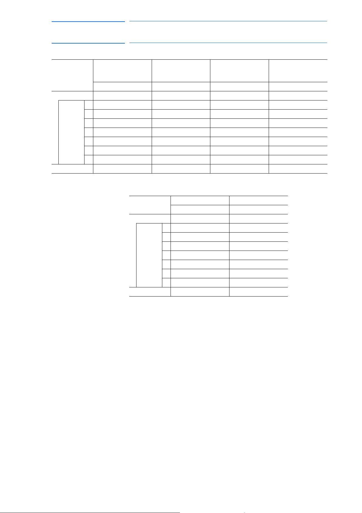
171768-1CD
65 of 764
DX100 European
Standard Maintenance
5 Replacing Parts
5.2 DX100 Parts List
Component MH50, MH50-20,
MH50-35
Model Model Model Model
SERVOPACK JZRCR-YSV04-11 JZRCR-YSV05-11 JZRCR-YSV05-41 JZRCR-YSV06-11
Amplifier S SRDA-SDA71A01A-E SRDA-SDA71A01A-E SRDA-SDA71A01A-E SRDA-SDA71A01A-E
L SRDA-SDA71A01A-E SRDA-SDA71A01A-E SRDA-SDA71A01A-E SRDA-SDA71A01A-E
U SRDA-SDA35A01A-E SRDA-SDA71A01A-E SRDA-SDA71A01A-E SRDA-SDA71A01A-E
R SRDA-SDA14A01A-E SRDA-SDA14A01A-E SRDA-SDA14A01A-E SRDA-SDA35A01A-E
B SRDA-SDA14A01A-E SRDA-SDA14A01A-E SRDA-SDA14A01A-E SRDA-SDA21A01A-E
T SRDA-SDA14A01A-E SRDA-SDA14A01A-E SRDA-SDA14A01A-E SRDA-SDA21A01A-E
E SRDA-SDA71A01A-E
Converter SRDA-COA30A01A-E SRDA-COA30A01A-E SRDA-COA30A01A-E SRDA-COA30A01A-E
Component UP350D MA1800
SERVOPACK JZRCR-YSV07-11 JZRCR-YSV08-11
Converter SRDA-COA30A01A-E SRDA-COA30A01A-E
MS80 VS50, SIA50D ES165D, ES165RD,
ES200D, ES200RD,
HP165D
Model Model
Amplifier S SRDA-SDA71A01A-E SRDA-SDA71A01A-E
L SRDA-SDA71A01A-E SRDA-SDA71A01A-E
U SRDA-SDA71A01A-E SRDA-SDA35A01A-E
R SRDA-SDA35A01A-E SRDA-SDA06A01A-E
B SRDA-SDA35A01A-E SRDA-SDA06A01A-E
T SRDA-SDA35A01A-E SRDA-SDA06A01A-E
E
5-30
RE-CHO-A109
Page 66

DX100 European
66 of 764
Standard Maintenance
5 Replacing Parts
5.3 Supplied Parts List
5.3 Supplied Parts List
The supplied parts of DX100 is as follows.
Parts No.1 to 3 are used for fuse for replacement and No.4, 5, and 6 are
used as a tool for connecting the I/O.
Table 5-3: Supplied Parts List
No. Parts Name Dimensions Pcs. Model Application
1 10 A
Glass-tube fuse
23.15 A
Glass-tube fuse
3 2.5 A
Alarm fuse
4 WAGO connector
wiring tool
5 WAGO connector
wiring tool
6 WAGO terminal
block wiring tool
2 0218010P
10 A, 250 V
(Littelfuse, Inc.)
3 02173.15P
3.15 A, 250 V
(Littelfuse, Inc.)
2 GP25 2.5 A
2.5 A, 250 V
(Daito Communication
Apparatus Co., Ltd.)
2 231-131
(WAGO Company of
Japan, Ltd.)
1 734-230
(WAGO Company of
Japan, Ltd.)
1 210-119SB
(WAGO Company of
Japan, Ltd.)
JZRCR-YPU01-
(1FU, 2FU)
JZNC-YSU01-E1(F1, F2)
JANCD-YBK01-E(F1)
JZNC-YIU0-E(F1, F2)
JZRCR-YPU01-
(3FU, 4FU)
JZNC-YPS01-E-CN152
JZNC-YIU0-E-CN303
JZNC-YSU01-1E-CN211
-X18
171768-1CD
5-31
RE-CHO-A109
Page 67

171768-1CD
NOTE
67 of 764
DX100 European
Standard Maintenance
5 Replacing Parts
5.4 Recommended Spare Parts
5.4 Recommended Spare Parts
It is recommended that the following parts and components be kept in
stock as spare parts for the DX100. The spare parts list for the DX100 is
shown below. Product performance can not be guaranteed when using
spare parts from any company other than Yaskawa. To buy the spare parts
which are ranked B or C, inform the manufacturing number (or order
number) of DX100 to Yaskawa representative. The spare parts are ranked
as follows:
• Rank A: Expendable and frequently replaced parts
• Rank B: Boards and sub-units
• Rank C: Units
For replacing parts in Rank B or Rank C, contact your
Yaskawa representative.
5-32
RE-CHO-A109
Page 68

DX100 European
68 of 764
Standard Maintenance
5 Replacing Parts
5.4 Recommended Spare Parts
Table 5-4: Recommended Spare Parts List of DX100 for MH5, MH5L
171768-1CD
Rank Parts
No.
A 1 Battery ER6VC3N 3.6 V Toshiba Home
A 2 CPS unit
A 3 Interior circulation
A 4 Backside duct fan 4715MS-22T-B5A-B00 Minebea Co., Ltd 2 2
A 5 AC control power
A 6 Brake fuse for AC
A 7 24 VDC fuse for I/O
C 8 Converter SRDA-COA12A01A-E Yaskawa 1 1 SERVOPACK:
B 9 Servo amplifier
B 10 Servo amplifier
B 11 Servo amplifier
B 12 Major axes control
C 13 CPU unit JZNC-YRK01-1E Yaskawa 1 1
B 14 Control circuit
B 15 Robot I/F board JANCD-YIF01-1E Yaskawa 1 1
C 16 Power supply
C 17 CPS unit JZNC-YPS01-E Yaskawa 1 1
B 18 Brake control board JANCD-YBK01-1E Yaskawa 1 1
C 19 Machine safety unit JANC-YSU01-1E Yaskawa 1 1
C 20 I/O unit JZNC-YIU02-E Yaskawa 1 1
C 21 Programming
1 The CPU unit (JZNC-YRK01-1E) does not include the robot I/F board
(JANCD-YIF01-1E). Must be ordered separately if required.
Name Type Manufacturer Qty. Qty.
per
Unit
11
Appliances
Corporation
JZNC-YZU01-E Yaskawa 1 1
cooling fan
4715MS-22T-B5A-B00 Minebea Co., Ltd 2 2
fan
0218010P Littelfuse, Inc. 2 2
supply fuse
cooling fan
brake power supply
fuse for external
axis
1, 2
3
4, 5, 6
circuit board
board
contactor unit
pendant
GP25 2.5 A 250 V Daito
Communication
Apparatus Co.,
Ltd.
02173.15P 3.15 A 250 V Littelfuse, Inc. 3 5
SRDA-SDA14A01A-E Yaskawa 2 2
SRDA-SDA06A01A-E Yaskawa 1 1
SRDA-SDA03A01A-E Yaskawa 3 3
SRDA-EAXA01A Yaskawa 1 1
JANCD-YCP01-E Yaskawa 1 1
JZRCR-YPU01-1 Yaskawa 1 1
JZRCR-YPP01-1 Yaskawa 1 1 With a cable
22
Remarks
JZRCRYSV01-11
1)
(8 meters)
5-33
RE-CHO-A109
Page 69

171768-1CD
69 of 764
DX100 European
Standard Maintenance
5 Replacing Parts
5.4 Recommended Spare Parts
Table 5-5: Recommended Spare Parts List of DX100 for MH6, MA1400
Rank Parts
No.
A 1 Battery ER6VC3N 3.6 V Toshiba Home
A 2 CPS unit cooling
A 3 Interior circulation
A 4 Backside duct fan 4715MS-22T-B5A-B00 Minebea Co., Ltd 2 2
A 5 AC control power
A 6 Brake fuse for AC
A 7 24 VDC fuse for I/O
C 8 Converter SRDA-COA12A01A-E Yaskawa 1 1 SERVOPACK:
B 9 Servo amplifier
B 10 Servo amplifier
B 11 Major axes control
C 12 CPU unit JZNC-YRK01-1E Yaskawa 1 1
B 13 Control circuit
B 14 Robot I/F board JANCD-YIF01-1E Yaskawa 1 1
C 15 Power supply
C 16 CPS unit JZNC-YPS01-E Yaskawa 1 1
B 17 Brake control board JANCD-YBK01-1E Yaskawa 1 1
C 18 Machine safety unit JZNC-YSU01-1E Yaskawa 1 1
C 19 I/O unit JZNC-YIU02-E Yaskawa 1 1
C 20 Programming
1 The CPU unit (JZNC-YRK01-1E) does not include the robot I/F board
(JANCD-YIF01-1E). Must be ordered separately if required.
Name Type Manufacturer Qty. Qty.
per
Unit
11
Appliances
Corporation
JZNC-YZU01-E Yaskawa 1 1
fan
4715MS-22T-B5A-B00 Minebea Co., Ltd 2 2
fan
0218010P Littelfuse, Inc. 2 2
supply fuse
cooling fan
brake power supply
fuse for external
axis
1, 2, 3
4, 5, 6
circuit board
board
contactor unit
pendant
GP25 2.5 A 250 V Daito
Communication
Apparatus Co.,
Ltd.
02173.15P 3.15 A 250 V Littelfuse, Inc. 3 5
SRDA-SDA14A01A-E Yaskawa 3 3
SRDA-SDA06A01A-E Yaskawa 3 3
SRDA-EAXA01A Yaskawa 1 1
JANCD-YCP01-E Yaskawa 1 1
JZRCR-YPU01-1 Yaskawa 1 1
JZRCR-YPP01-1 Yaskawa 1 1 With a cable
22
Remarks
JZRCRYSV02-11
1)
(8 meters)
5-34
RE-CHO-A109
Page 70

DX100 European
70 of 764
Standard Maintenance
5 Replacing Parts
5.4 Recommended Spare Parts
Table 5-6: Recommended Spare Parts List of DX100 for VA1400
171768-1CD
Rank Parts
No.
A 1 Battery ER6VC3N 3.6 V Toshiba Home
A 2 CPS unit cooling
A 3 Interior circulation
A 4 Backside duct fan 4715MS-22T-B5A-B00 Minebea Co., Ltd 2 2
A 5 AC control power
A 6 Brake Fuse for AC
A 7 24 VDC fuse for I/O
C 8 Converter SRDA-COA12A01A-E Yaskawa 1 1 SERVOPACK:
B 9 Servo amplifier
B 10 Servo amplifier
B 11 Major axes control
B 12 External axis
C 13 CPU unit JZNC-YRK01-1E Yaskawa 1 1
B 14 Control circuit
B 15 Robot I/F board JANCD-YIF01-1E Yaskawa 1 1
C 16 Power supply
C 17 CPS unit JZNC-YPS01-E Yaskawa 1 1
B 18 Brake control board JANCD-YBK01-1E Yaskawa 1 1
C 19 Machine safety unit JZNC-YSU01-1E Yaskawa 1 1
C 20 I/O unit JZNC-YIU02-E Yaskawa 1 1
C 21 Programming
1 The CPU unit (JZNC-YRK01-1E) does not include the robot I/F board
(JANCD-YIF01-1E). Must be ordered separately if required.
Name Type Manufacturer Qty. Qty.
per
Unit
11
Appliances
Corporation
JZNC-YZU01-E Yaskawa 1 1
fan
4715MS-22T-B5A-B00 Minebea Co., Ltd 2 2
fan
0218010P Littelfuse, Inc. 2 2
supply fuse
Cooling Fan
brake power supply
fuse for external
axis
1, 2, 3, 7
4, 5, 6
circuit board
control circuit board
board
contactor unit
pendant
GP25 2.5 A 250 V Daito
Communication
Apparatus Co.,
Ltd.
02173.15P 3.15 A 250 V Littelfuse, Inc. 3 5
SRDA-SDA14A01A-E Yaskawa 4 4
SRDA-SDA06A01A-E Yaskawa 3 3
SRDA-EAXA01A Yaskawa 1 1
SRDA-EAXB01A Yaskawa 1 1
JANCD-YCP01-E Yaskawa 1 1
JZRCR-YPU01-1 Yaskawa 1 1
JZRCR-YPP01-1 Yaskawa 1 1 With a cable
22
Remarks
JZRCRYSV02-31
1)
(8 meters)
5-35
RE-CHO-A109
Page 71

171768-1CD
71 of 764
DX100 European
Standard Maintenance
5 Replacing Parts
5.4 Recommended Spare Parts
Table 5-7: Recommended Spare Parts List of DX100 for MA1900, HP20D, HP20D-6, HP20RD
Rank Parts
No.
A 1 Battery ER6VC3N 3.6 V Toshiba Home
A 2 CPS unit cooling
A 3 Interior circulation
A 4 Backside duct fan 4715MS-22T-B5A-B00 Minebea Co., Ltd 2 2
A 5 AC control power
A 6 Brake fuse for AC
A 7 24 VDC fuse for I/O
C 8 Converter SRDA-COA12A01A-E Yaskawa 1 1 SERVOPACK:
B 9 Servo amplifier
B 10 Servo amplifier
B 11 Servo amplifier
B 12 Major axes control
C 13 CPU unit JZNC-YRK01-1E Yaskawa 1 1
B 14 Control circuit
B 15 Robot I/F board JANCD-YIF01-1E Yaskawa 1 1
C 16 Power supply
C 17 CPS unit JZNC-YPS01-E Yaskawa 1 1
B 18 Brake control board JANCD-YBK01-1E Yaskawa 1 1
C 19 Machine safety unit JZNC-YSU01-1E Yaskawa 1 1
C 20 I/O unit JZNC-YIU02-E Yaskawa 1 1
C 21 Programming
1 The CPU unit (JZNC-YRK01-1E) does not include the robot I/F board
(JANCD-YIF01-1E). Must be ordered separately if required.
Name Type Manufacturer Qty. Qty.
per
Unit
11
Appliances
Corporation
JZNC-YZU0-E Yaskawa 1 1
fan
4715MS-22T-B5A-B00 Minebea Co., Ltd 2 2
fan
0218010P Littelfuse, Inc. 2 2
supply fuse
cooling fan
brake power supply
fuse for external
axis
1, 3
2
4, 5, 6
circuit board
board
contactor unit
pendant
GP25 2.5 A 250 V Daito
Communication
Apparatus Co.,
Ltd.
02173.15P 3.15 A 250 V Littelfuse, Inc. 3 5
SRDA-SDA14A01A-E Yaskawa 2 2
SRDA-SDA21A01A-E Yaskawa 1 1
SRDA-SDA06A01A-E Yaskawa 3 3
SRDA-EAXA01A Yaskawa 1 1
JANCD-YCP01-E Yaskawa 1 1
JZRCR-YPU01-1 Yaskawa 1 1
JZRCR-YPP01-1 Yaskawa 1 1 With a cable
22
Remarks
JZRCRYSV03-11
1)
(8 meters)
5-36
RE-CHO-A109
Page 72

DX100 European
72 of 764
Standard Maintenance
5 Replacing Parts
5.4 Recommended Spare Parts
Table 5-8: Recommended Spare Parts List of DX100 for MH50, MH50-20, MH50-35
171768-1CD
Rank Parts
No.
A 1 Battery ER6VC3N 3.6 V Toshiba Home
A 2 CPS unit cooling
A 3 Interior circulation
A 4 Backside duct fan 4715MS-22T-B5A-B00 Minebea Co., Ltd 2 2
A 5 AC control power
A 6 Brake fuse for AC
A 7 24 VDC fuse for I/O
C 8 Converter SRDA-COA30A01A-E Yaskawa Electric
B 9 Servo amplifier
B 10 Servo amplifier
B 11 Servo amplifier
B 12 Major axes control
C 13 CPU unit JZNC-YRK01-1E Yaskawa 1 1
B 14 Control circuit
B 15 Robot I/F board JANCD-YIF01-1E Yaskawa 1 1
C 16 Power supply
C 17 CPS unit JZNC-YPS01-E Yaskawa 1 1
B 18 Brake control board JANCD-YBK01-1E Yaskawa 1 1
C 19 Machine safety unit JZNC-YSU01-1E Yaskawa 1 1
C 20 I/O unit JZNC-YIU02-E Yaskawa 1 1
C 21 Programming
1 The CPU unit (JZNC-YRK01-1E) does not include the robot I/F board
(JANCD-YIF01-1E). Must be ordered separately if required.
Name Type Manufacturer Qty. Qty.
11
Appliances
Corporation
JZNC-YZU01-E Yaskawa 1 1
fan
4715MS-22T-B5A-B00 Minebea Co., Ltd 2 2
fan
0218010P Littelfuse, Inc. 2 2
supply fuse
cooling fan
brake power supply
fuse for external
axis
1, 2
3
4, 5, 6
circuit board
board
contactor unit
pendant
GP25 2.5 A 250 V Daito
Communication
Apparatus Co.,
Ltd.
02173.15P 3.15 A 250 V Littelfuse, Inc. 3 5
Corporation
SRDA-SDA71A01A-E Yaskawa 2 2 SERVOPACK:
SRDA-SDA35A01A-E Yaskawa 1 1
SRDA-SDA14A01A-E Yaskawa 3 3
SRDA-EAXA01A Yaskawa 1 1
JANCD-YCP01-E Yaskawa 1 1
JZRCR-YPU01-1 Yaskawa 1 1
JZRCR-YPP01-1 Yaskawa 1 1 With a cable
22
11
Remarks
per
Unit
JZRCR-
YSV04-11
1)
(8 meters)
5-37
RE-CHO-A109
Page 73
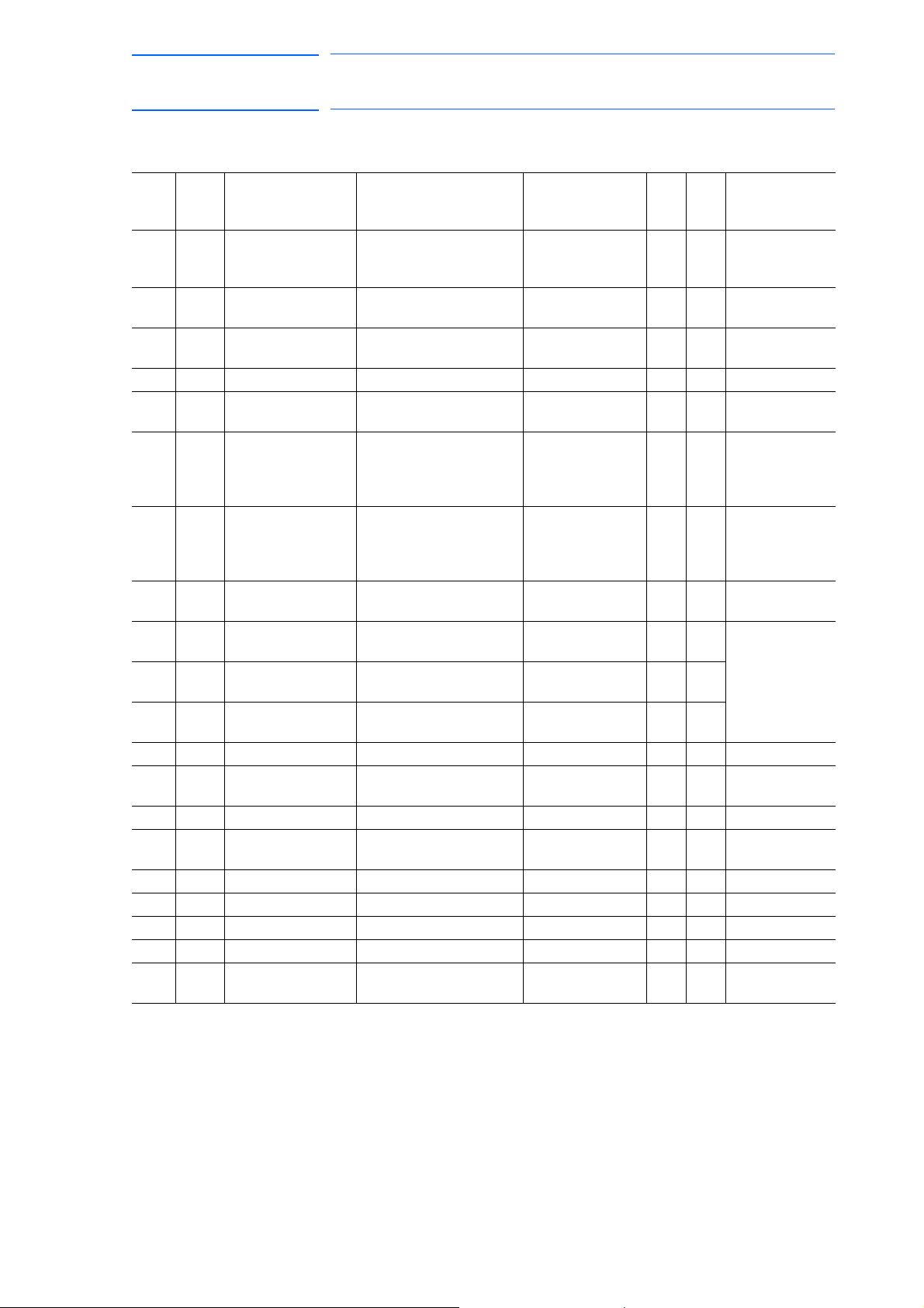
171768-1CD
73 of 764
DX100 European
Standard Maintenance
5 Replacing Parts
5.4 Recommended Spare Parts
Table 5-9: Recommended Spare Parts List of DX100 for MS80
Rank Parts
No.
A 1 Battery ER6VC3N 3.6 V Toshiba Home
A 2 CPS unit
A 3 Interior circulation
A 4 Backside duct fan 4715MS-22T-B5A-B00 Minebea Co., Ltd 2 2
A 5 AC control power
A 6 Brake fuse for AC
A 7 24 VDC fuse for I/O
C 8 Converter SRDA-COA30A01A-E Yaskawa Electric
B 9 Servo amplifier
B 10 Servo amplifier
B 11 Major axes control
C 12 CPU unit JZNC-YRK01-1E Yaskawa 1 1
B 13 Control circuit
B 14 Robot I/F board JANCD-YIF01-1E Yaskawa 1 1
C 15 Power supply
C 16 CPS unit JZNC-YPS01-E Yaskawa 1 1
B 17 Brake control board JANCD-YBK01-1E Yaskawa 1 1
C 18 Machine safety unit JZNC-YSU01-1E Yaskawa 1 1
C 19 I/O unit JZNC-YIU02-E Yaskawa 1 1
C 20 Programming
1 The CPU unit (JZNC-YRK01-1E) does not include the robot I/F board
(JANCD-YIF01-1E). Must be ordered separately if required.
Name Type Manufacturer Qty. Qty.
11
Appliances
Corporation
JZNC-YZU01-E Yaskawa 1 1
cooling fan
4715MS-22T-B5A-B00 Minebea Co., Ltd 2 2
fan
0218010P Littelfuse, Inc. 2 2
supply fuse
cooling fan
brake power supply
fuse for external
axis
1, 2, 3
4, 5, 6
circuit board
board
contactor unit
pendant
GP25 2.5 A 250 V Daito
Communication
Apparatus Co.,
Ltd.
02173.15P 3.15 A 250 V Littelfuse, Inc. 3 5
Corporation
SRDA-SDA71A01A-E Yaskawa 3 3 SERVOPACK:
SRDA-SDA14A01A-E Yaskawa 3 3
SRDA-EAXA01A Yaskawa 1 1
JANCD-YCP01-E Yaskawa 1 1
JZRCR-YPU01-1 Yaskawa 1 1
JZRCR-YPP01-1 Yaskawa 1 1 With a cable
22
11
Remarks
per
Unit
JZRCR-
YSV05-11
1)
(8 meters)
5-38
RE-CHO-A109
Page 74
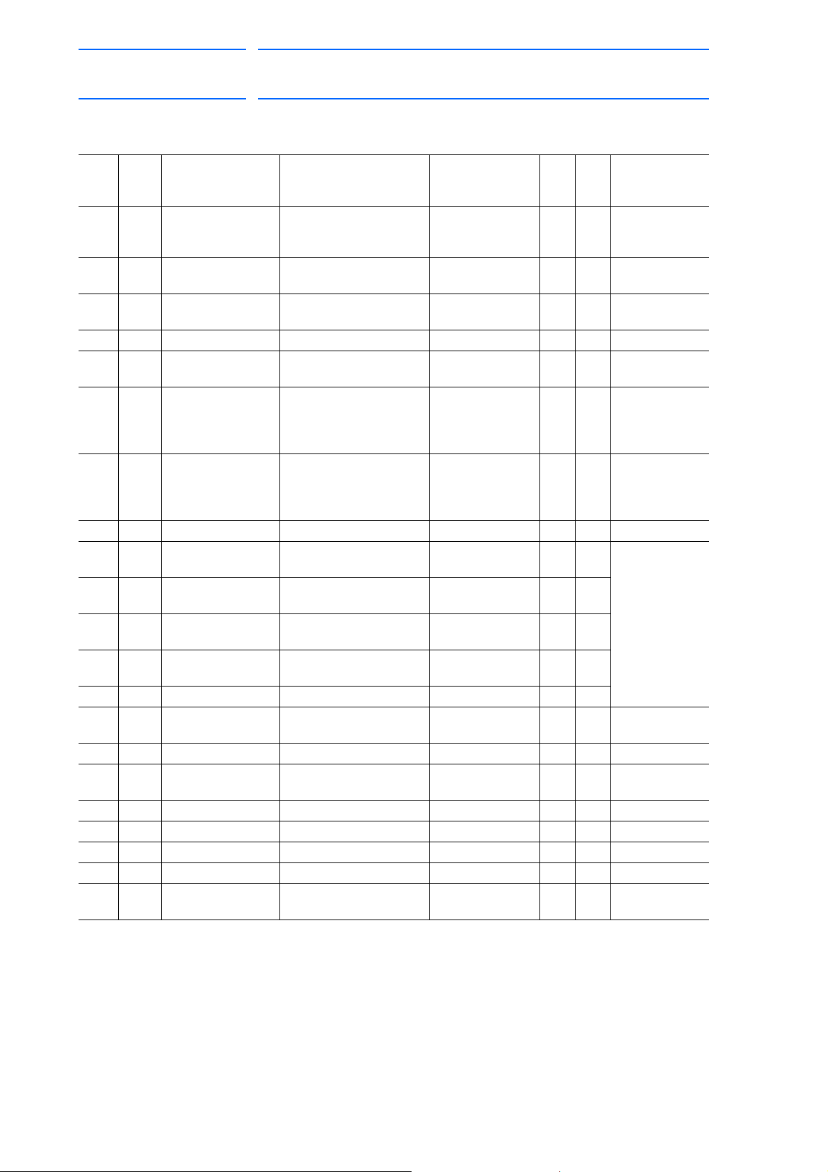
DX100 European
74 of 764
Standard Maintenance
5 Replacing Parts
5.4 Recommended Spare Parts
Table 5-10: Recommended Spare Parts List of DX100 for VS50, SIA50D
171768-1CD
Rank Parts
No.
A 1 Battery ER6VC3N 3.6 V Toshiba Home
A 2 CPS unit cooling
A 3 Interior circulation
A 4 Backside duct fan 4715MS-22T-B5A-B00 Minebea Co., Ltd 2 2
A 5 AC control power
A 6 Brake fuse for AC
A 7 24 VDC fuse for I/O
C 8 Converter SRDA-COA30A01A-E Yaskawa 1 1
B 9 Servo amplifier
B 10 Servo amplifier
B 11 Major axes control
B 12 External axis
C 13 CPU unit JZNC-YRK01-1E Yaskawa 1 1
B 14 Control circuit
B 15 Robot I/F board JANCD-YIF01-1E Yaskawa 1 1
C 16 Power supply
C 17 CPS unit JZNC-YPS01-E Yaskawa 1 1
B 18 Brake control board JANCD-YBK01-1E Yaskawa 1 1
C 19 Machine safety unit JZNC-YSU01-1E Yaskawa 1 1
C 20 I/O unit JZNC-YIU02-E Yaskawa 1 1
C 21 Programming
1 The CPU unit (JZNC-YRK01-1E) does not include the robot I/F board
(JANCD-YIF01-1E). Must be ordered separately if required.
Name Type Manufacturer Qty. Qty.
11
Appliances
Corporation
JZNC-YZU01-E Yaskawa 1 1
fan
4715MS-22T-B5A-B00 Minebea Co., Ltd 2 2
fan
0218010P Littelfuse, Inc. 2 2
supply fuse
cooling fan
brake power supply
fuse for external
axis
1, 2, 3, 7
4, 5, 6
circuit board
control circuit board
board
contactor unit
pendant
GP25 2.5 A 250 V Daito
Communication
Apparatus Co.,
Ltd.
02173.15P 3.15 A 250 V Littelfuse, Inc. 3 5
SRDA-SDA71A01A-E Yaskawa 4 4 SERVOPACK:
SRDA-SDA14A01A-E Yaskawa 3 3
SRDA-EAXA01A Yaskawa 1 1
SRDA-EAXB01A Yaskawa 1 1
JANCD-YCP01-E Yaskawa 1 1
JZRCR-YPU01-1 Yaskawa 1 1
JZRCR-YPP01-1 Yaskawa 1 1 With a cable
22
Remarks
per
Unit
JZRCR-
YSV05-41
1)
(8 meters)
5-39
RE-CHO-A109
Page 75

171768-1CD
75 of 764
DX100 European
Standard Maintenance
5 Replacing Parts
5.4 Recommended Spare Parts
Table 5-11: Recommended Spare Parts List of DX100 for ES165D, ES165RD, ES200D, ES200RD,
HP165D
Rank Parts
No.
A 1 Battery ER6VC3N 3.6 V Toshiba Home
A 2 CPS unit cooling
A 3 Interior circulation
A 4 Backside duct fan 4715MS-22T-B5A-B00 Minebea Co., Ltd 2 2
A 5 AC control power
A 6 Brake fuse for AC
A 7 24 VDC fuse for I/O
C 8 Converter SRDA-COA30A01A-E Yaskawa 1 1
B 9 Servo amplifier
B 10 Servo amplifier
B 11 Servo amplifier
B 12 Major axes control
C 13 CPU unit JZNC-YRK01-1E Yaskawa 1 1
B 14 Control circuit
B 15 Robot I/F board JANCD-YIF01-1E Yaskawa 1 1
C 16 Power supply
C 17 CPS unit JZNC-YPS01-E Yaskawa 1 1
B 18 Brake control board JANCD-YBK01-1E Yaskawa 1 1
C 19 Machine safety unit JZNC-YSU01-1E Yaskawa 1 1
C 20 I/O unit JZNC-YIU02-E Yaskawa 1 1
C 21 Programming
1 The CPU unit (JZNC-YRK01-1E) does not include the robot I/F board
(JANCD-YIF01-1E). Must be ordered separately if required.
Name Type Manufacturer Qty. Qty.
11
Appliances
Corporation
JZNC-YZU01-E Yaskawa 1 1
fan
4715MS-22T-B5A-B00 Minebea Co., Ltd 2 2
fan
0218010P Littelfuse, Inc. 2 2
supply fuse
cooling fan
brake power supply
fuse for external
axis
1, 2, 3
4
5, 6
circuit board
board
contactor unit
pendant
GP25 2.5 A 250 V Daito
Communication
Apparatus Co.,
Ltd.
02173.15P 3.15 A 250 V Littelfuse, Inc. 3 5
SRDA-SDA71A01A-E Yaskawa 3 3 SERVOPACK:
SRDA-SDA35A01A-E Yaskawa 1 1
SRDA-SDA21A01A-E Yaskawa 2 2
SRDA-EAXA01A Yaskawa 1 1
JANCD-YCP01-E Yaskawa 1 1
JZRCR-YPU01-1 Yaskawa 1 1
JZRCR-YPP01-1 Yaskawa 1 1 With a cable
22
Remarks
per
Unit
JZRCR-
YSV06-11
1)
(8 meters)
5-40
RE-CHO-A109
Page 76
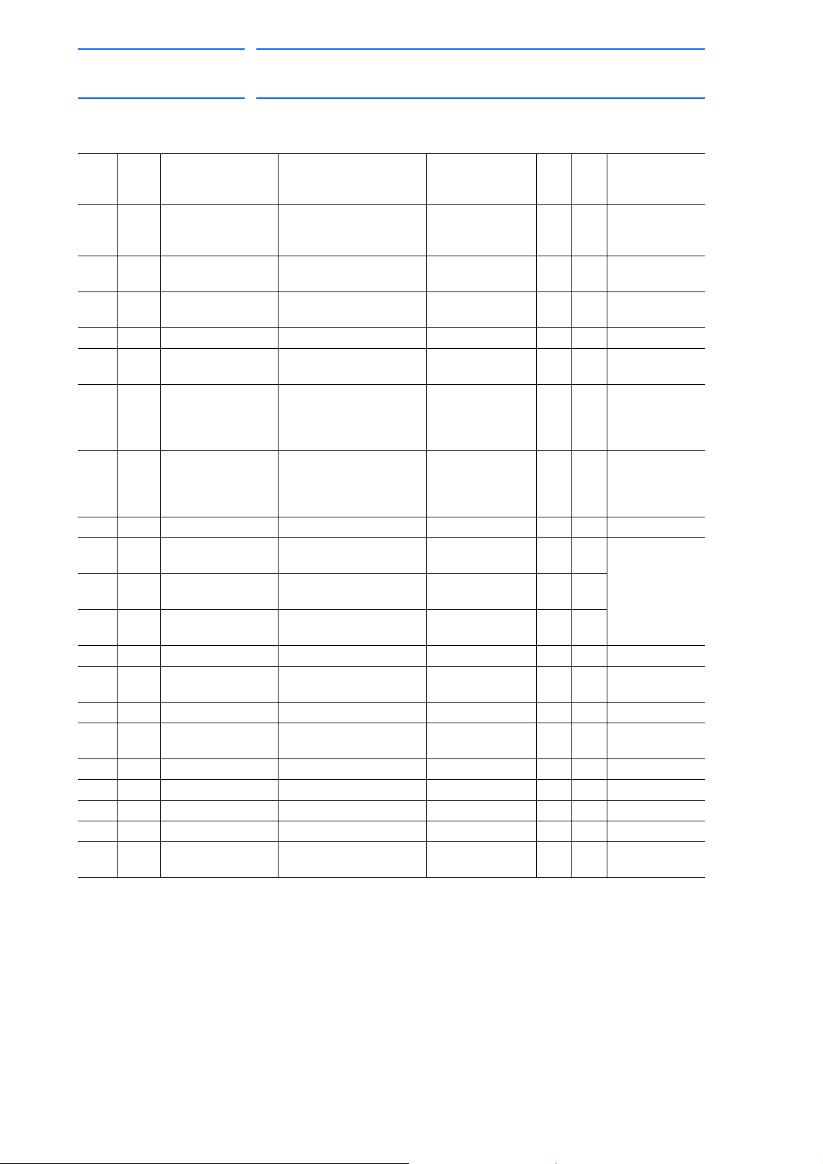
DX100 European
76 of 764
Standard Maintenance
5 Replacing Parts
5.4 Recommended Spare Parts
Table 5-12: Recommended Spare Parts List of DX100 for UP350D
171768-1CD
Rank Parts
No.
A 1 Battery ER6VC3N 3.6 V Toshiba Home
A 2 CPS unit cooling
A 3 Interior circulation
A 4 Backside duct fan 4715MS-22T-B5A-B00 Minebea Co., Ltd 2 2
A 5 AC control power
A 6 Brake fuse for AC
A 7 24 VDC fuse for I/O
C 8 Converter SRDA-COA30A01A-E Yaskawa 1 1
B 9 Servo amplifier
B 10 Servo amplifier
B 11 Major axes control
C 12 CPU unit JZNC-YRK01-1E Yaskawa 1 1
B 13 Control circuit
B 14 Robot I/F board JANCD-YIF01-1E Yaskawa 1 1
C 15 Power supply
C 16 CPS unit JZNC-YPS01-E Yaskawa 1 1
B 17 Brake control board JANCD-YBK01-1E Yaskawa 1 1
C 18 Machine safety unit JZNC-YSU01-1E Yaskawa 1 1
C 19 I/O unit JZNC-YIU02-E Yaskawa 1 1
C 20 Programming
1 The CPU unit (JZNC-YRK01-1E) does not include the robot I/F board
(JANCD-YIF01-1E). Must be ordered separately if required.
Name Type Manufacturer Qty. Qty.
11
Appliances
Corporation
JZNC-YZU01-E Yaskawa 1 1
fan
4715MS-22T-B5A-B00 Minebea Co., Ltd 2 2
fan
0218010P Littelfuse, Inc. 2 2
supply fuse
cooling fan
brake power supply
fuse for external
axis
1, 2, 3
4, 5, 6
circuit board
board
contactor unit
pendant
GP25 2.5 A 250 V Daito
Communication
Apparatus Co.,
Ltd.
02173.15P 3.15 A 250 V Littelfuse, Inc. 3 5
SRDA-SDA71A01A-E Yaskawa 3 3 SERVOPACK:
SRDA-SDA35A01A-E Yaskawa 3 3
SRDA-EAXA01A Yaskawa 1 1
JANCD-YCP01-E Yaskawa 1 1
JZRCR-YPU01-1 Yaskawa 1 1
JZRCR-YPP01-1 Yaskawa 1 1 With a cable
22
Remarks
per
Unit
JZRCR-
YSV07-11
1)
(8 meters)
5-41
RE-CHO-A109
Page 77
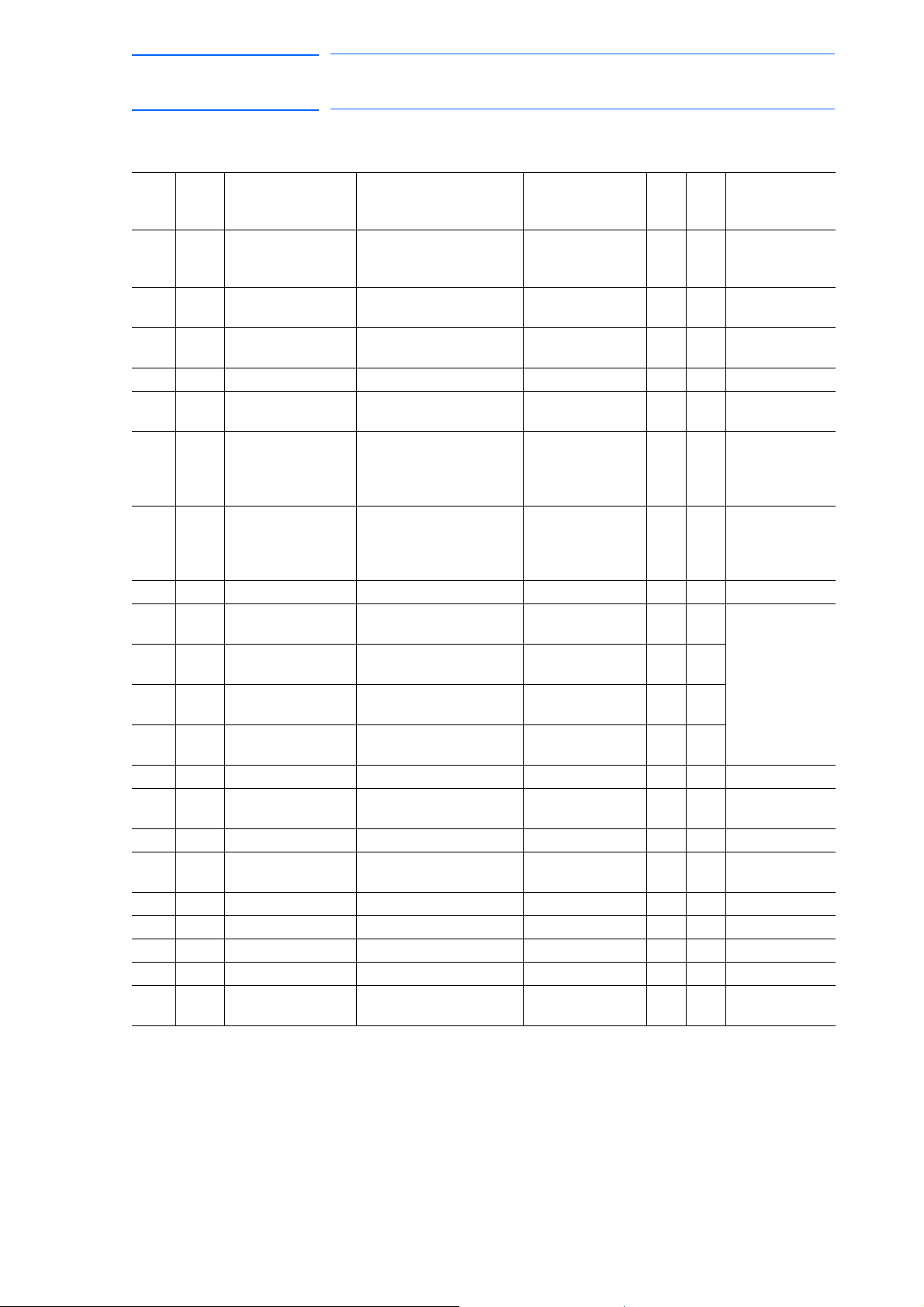
171768-1CD
77 of 764
DX100 European
Standard Maintenance
5 Replacing Parts
5.4 Recommended Spare Parts
Table 5-13: Recommended Spare Parts List of DX100 for MA1800
Rank Parts
No.
A 1 Battery ER6VC3N 3.6 V Toshiba Home
A 2 CPS unit cooling
A 3 Interior circulation
A 4 Backside duct fan 4715MS-22T-B5A-B00 Minebea Co., Ltd 2 2
A 5 AC control power
A 6 Brake fuse for AC
A 7 24 VDC fuse for I/O
C 8 Converter SRDA-COA30A01A-E Yaskawa 1 1
B 9 Servo amplifier
B 10 Servo amplifier
B 11 Servo amplifier
B 12 Major axes control
C 13 CPU unit JZNC-YRK01-1E Yaskawa 1 1
B 14 Control circuit
B 15 Robot I/F board JANCD-YIF01-1E Yaskawa 1 1
C 16 Power supply
C 17 CPS unit JZNC-YPS01-E Yaskawa 1 1
B 18 Brake control board JANCD-YBK01-1E Yaskawa 1 1
C 19 Machine safety unit JZNC-YSU01-1E Yaskawa 1 1
C 20 I/O unit JZNC-YIU02-E Yaskawa 1 1
C 21 Programming
1 The CPU unit (JZNC-YRK01-1E) does not include the robot I/F board
(JANCD-YIF01-1E). Must be ordered separately if required.
Name Type Manufacturer Qty. Qty.
11
Appliances
Corporation
JZNC-YZU01-E Yaskawa 1 1
fan
4715MS-22T-B5A-B00 Minebea Co., Ltd 2 2
fan
0218010P Littelfuse, Inc. 2 2
supply fuse
cooling fan
brake power supply
fuse for external
axis
1, 2
3
4, 5, 6
circuit board
board
contactor unit
pendant
GP25 2.5 A 250 V Daito
Communication
Apparatus Co.,
Ltd.
02173.15P 3.15 A 250 V Littelfuse, Inc. 3 5
SRDA-SDA71A01A-E Yaskawa 2 2 SERVOPACK:
SRDA-SDA35A01A-E Yaskawa 1 1
SRDA-SDA06A01A-E Yaskawa 3 3
SRDA-EAXA01A Yaskawa 1 1
JANCD-YCP01-E Yaskawa 1 1
JZRCR-YPU01-1 Yaskawa 1 1
JZRCR-YPP01-1 Yaskawa 1 1 With a cable
22
Remarks
per
Unit
JZRCR-
YSV08-11
1)
(8 meters)
5-42
RE-CHO-A109
Page 78
DX100 European
WARNING
78 of 764
Standard Maintenance
6 Operations After Replacing Parts
6 Operations After Replacing Parts
• Before operating the manipulator, check that the SERVO ON
lamp turns OFF when the emergency stop buttons on the front
door of the DX100 and the programming pendant are pressed.
Injury or damage to machinery may result if the manipulator cannot be
stopped in case of an emergency.
• Observe the following precautions when performing teaching
operations within the P-point maximum envelope of the
manipulator:
– Be sure to use a lockout device to the safeguarding when
going inside. Also, display the sign that the operation is
being performed inside the safeguarding and make sure no
one closes the safeguarding.
171768-1CD
– View the manipulator from the front whenever possible.
– Always follow the predetermined operating procedure.
– Ensure that you have a safe place to retreat in case of
emergency.
Improper or unintended manipulator operation may result in injury.
• Confirm that no persons are present in the P-point maximum
envelope of the manipulator and that you are in a safe location
before:
– Turning ON the DX100 power.
– Moving the manipulator with the programming pendant
Injury may result if anyone enters the P-point maximum envelope of the
manipulator during operation.
• Always press the emergency stop button immediately if there
are problems.
Emergency stop buttons are located at the upper right corner of the
front door of the DX100 and on the upper right of the programming
pendant.
6-1
RE-CHO-A109
Page 79
171768-1CD
CAUTION
NOTE
79 of 764
DX100 European
Standard Maintenance
6 Operations After Replacing Parts
6.1 Home Position Calibration
• Perform the following inspection procedures prior to
conducting manipulator teaching. If problems are found, repair
them immediately, and be sure that all other necessary
processing has been performed.
– Check for problems in manipulator movement.
– Check for damage to insulation and sheathing of external
wires.
– Always return the programming pendant to the hook on the
DX100 cabinet after use.
The programming pendant can be damaged if it is left in the P-point
maximum envelope of the manipulator, on the floor, or near fixtures.
6.1 Home Position Calibration
6.1.1 Home Position Calibration
Teaching and playback are not possible before home
position calibration is complete.
In a system with two or more manipulators, the home
position of all the manipulators must be calibrated before
starting teaching or playback.
Set the security mode to the management mode to perform
home position calibration.
Home position calibration is an operation in which the home position and
absolute encoder position coincide. Although this operation is performed
prior to shipment at the factory, the following cases require this operation
to be performed again.
• Change in the combination of the manipulator and DX100
• Replacement of the motor or absolute encoder
• Clearing stored memory (by replacement of NIF01 circuit board,
weak battery, etc.)
• Home position deviation caused by hitting the manipulator against a
workpiece, etc.
6-2
RE-CHO-A109
Page 80

DX100 European
SUPPLE-
MENT
80 of 764
Standard Maintenance
171768-1CD
6 Operations After Replacing Parts
6.1 Home Position Calibration
To calibrate the home position, use the axis keys to calibrate the mark for
the home position on each axis so that the manipulator can take its
posture for the home position. There are two operations for home position
calibration:
• All the axes can be moved at the same time
• Axes can be moved individually
If the absolute data of the home position is already known, set the
absolute data again after completing home position registration.
Home Position
The home position is the position with the pulse value “0” for
each axis. See section 6.1.3 “Manipulator Home Position” on
page 6-9.
6-3
RE-CHO-A109
Page 81

171768-1CD
PAGE
GO BACK
PAGE
GO BACK
81 of 764
DX100 European
Standard Maintenance
6 Operations After Replacing Parts
6.1 Home Position Calibration
6.1.2 Calibrating Operation
6.1.2.1 Registering All Axes at One Time
1. Select {ROBOT} under the main menu.
2. Select {HOME POSITION}.
– The HOME POSITIONING window appears.
3. Select {DISPLAY} under the menu,
or select “PAGE” to display the select
or press .
– The pull-down menu appears.
ion window for the control group,
6-4
RE-CHO-A109
Page 82
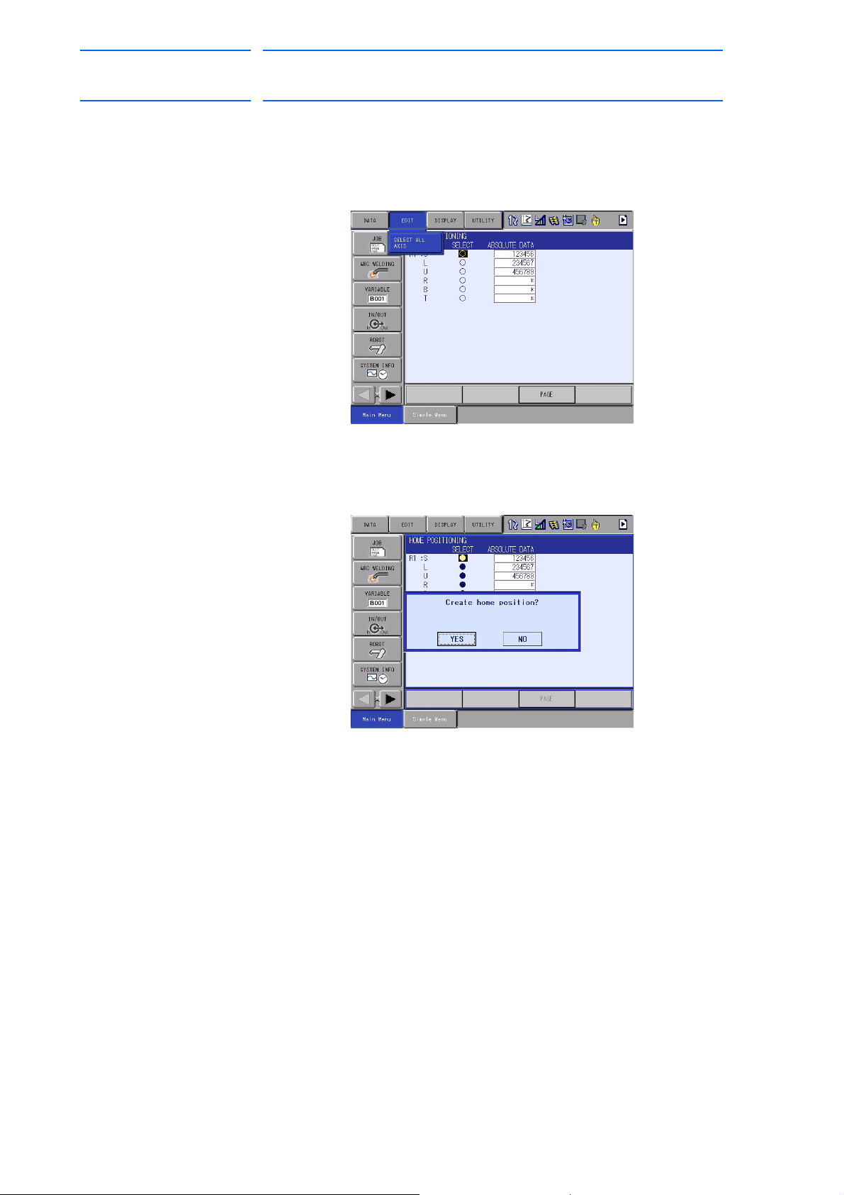
DX100 European
82 of 764
Standard Maintenance
171768-1CD
6 Operations After Replacing Parts
6.1 Home Position Calibration
4. Select the desired control group.
5. Select {EDIT} under the menu.
– The pull-down menu appears.
6. Select {SELECT ALL
– The confirmation dialog box appears.
7. Select “YES.”
– Displayed position data of all axes ar
6.1.2.2 Registering Individual Axes
AXES}.
e registered as home position.
When “NO” is selected, the registration will be canceled.
1. Select {ROBOT} under the main menu.
2. Select {HOME POSITION}.
3. Select the desired control group.
– Perform steps 3 and 4 in section 6.1.2.1 “Registering All Axes at
One Time” to select the desired control group.
6-5
RE-CHO-A109
Page 83

171768-1CD
83 of 764
DX100 European
Standard Maintenance
6 Operations After Replacing Parts
6.1 Home Position Calibration
4. Select the axis to be registered.
– The confirmation dialog box appears.
5. Select “YES”.
– Displayed position data of the axis are registered as home position.
When “NO” is selected, the registration will be canceled.
6-6
RE-CHO-A109
Page 84

DX100 European
84 of 764
Standard Maintenance
6.1.2.3 Changing the Absolute Data
6 Operations After Replacing Parts
6.1 Home Position Calibration
To change the absolute data of the axis when home position calibration is
completed, perform the following:
1. Select {ROBOT} under the main menu.
2. Select {HOME POSITION}.
3. Select the desired control group.
171768-1CD
– Perform steps 3 and 4 in se
One Time” to select the desired control group
4. Select the absolute data to be registered.
– The number can now be entered.
5. Enter the absolute data using the numeric keys.
6. Press [ENTER].
– Absolute data are modified.
ction 6.1.2.1 “Registering All Axes at
6.1.2.4 Clearing
Absolute Data
1. Select {ROBOT} under the main menu.
2. Select {HOME POSITION}.
– Perform steps 2, 3, and 4 in section 6.1.2.1 “Registering All Axes at
One Time” to display the HOME POSITIONING window and select
the desired control group.
6-7
RE-CHO-A109
Page 85

171768-1CD
85 of 764
DX100 European
Standard Maintenance
6 Operations After Replacing Parts
6.1 Home Position Calibration
3. Select {DATA} under the menu.
– The pull-down menu appears.
4. Select {CLEAR ALL DATA}.
– The confirmation dialog box appears.
5. Select “YES”.
– The all absolute data are cleared. When “NO” is selected, the
operation will be canceled.
6-8
RE-CHO-A109
Page 86

DX100 European
NOTE
U-axis angle against horizontal
line on the ground (-0°)
L-axis angle against vertical
line to the ground (-0°)
B-axis center line angle against
U-axis center line (-0°)
86 of 764
Standard Maintenance
6.1.3 Manipulator Home Position
171768-1CD
6 Operations After Replacing Parts
6.1 Home Position Calibration
With the MOTOMAN-VA1400, the home position is as follows.
Other manipulator models have different positions. Always
consult the documentation for the correct manipulator
model.
6-9
RE-CHO-A109
Page 87
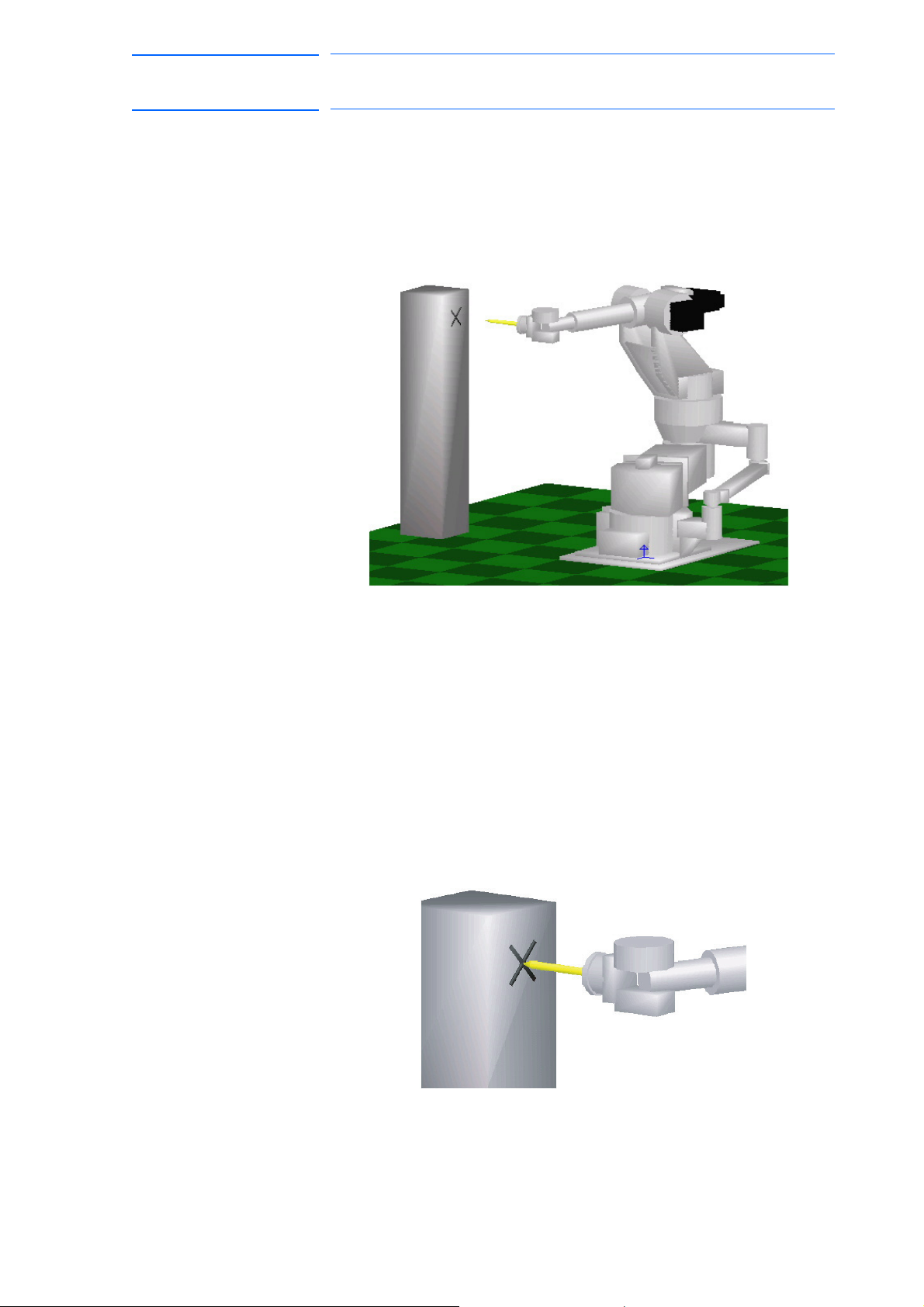
171768-1CD
87 of 764
DX100 European
Standard Maintenance
6 Operations After Replacing Parts
6.2 Position Deviation Check Using the Check Program
6.2 Position Deviation Check Using the Check Program
Use the check program to check if positions are deviated with the
following procedure.
1. Call up the check program in which the check point is taught (the job
for) and operate the manipulator at low speed.
2. Check the tool tip position.
– If it points the check point exactly as shown in the following figure,
th
ere is no deviation from the positions. Proceed to section 6.4
“Setting the Second Home Position (Check Point)” on page 6-13.
– If not, there is a deviation. When the motor or encoder, etc. was
replaced, move the corresponding axis only, when the stored
memory was cleared or the manipulator was hit against a
workpiece, move all axes, to the check point by joint motion. Then,
proceed to section 6.3.3 “Home Position Data Correction” on page
6-12.
6-10
RE-CHO-A109
Page 88
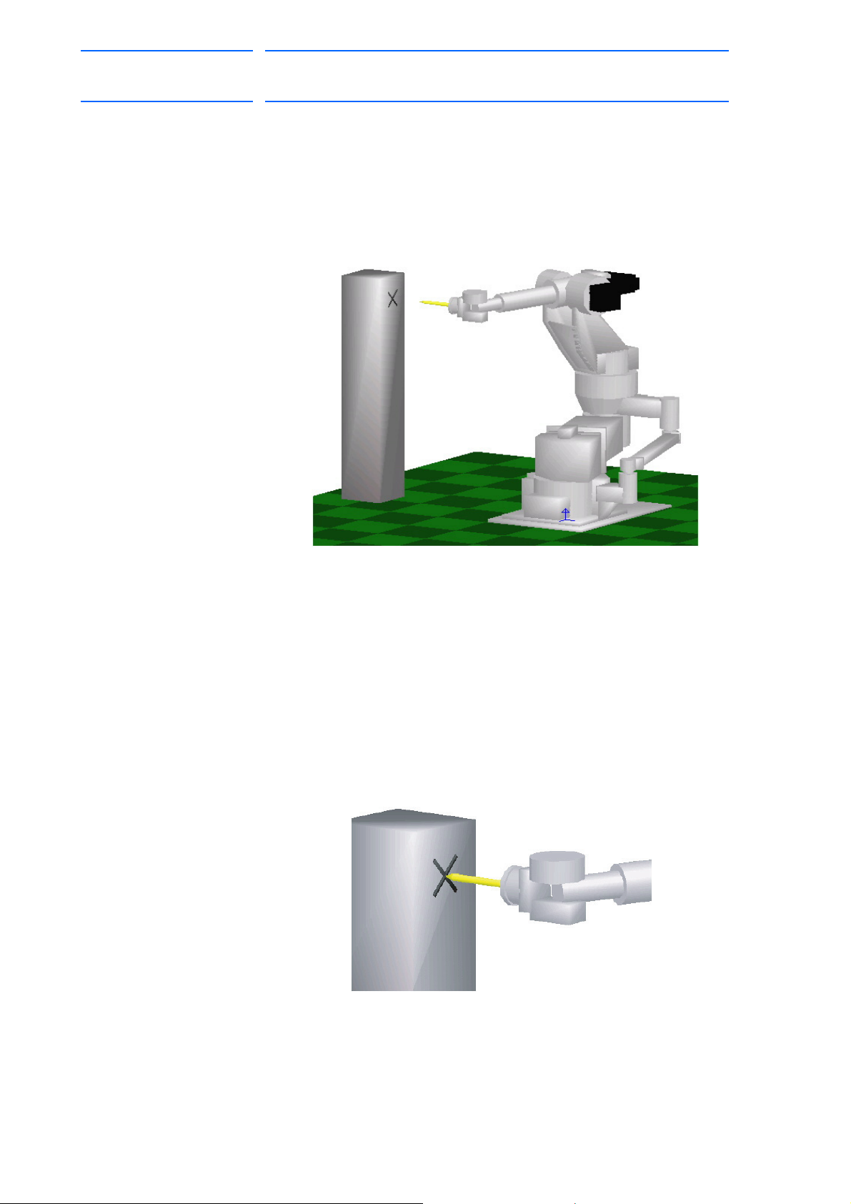
DX100 European
88 of 764
Standard Maintenance
6.3.1 Motion of the Check Program
171768-1CD
6 Operations After Replacing Parts
6.3 Checking of the Check Program
6.3 Checking of the Check Program
Call up the check program in which the check point is taught (the job for
avoiding the position deviation) and operate the manipulator at low speed.
6.3.2 Checking of the Check Program
Check the deviation in to the check point. If the tool tip position is
deviated, there is a deviation.
When the motor or encoder, etc. was replaced, move the corresponding
axis only, when the stored memory was cleared or the manipulator was hit
against a workpiece, move all axes, to the check point by joint motion.
6-11
RE-CHO-A109
Page 89

171768-1CD
89 of 764
DX100 European
Standard Maintenance
6 Operations After Replacing Parts
6.3 Checking of the Check Program
6.3.3 Home Position Data Correction
When there is a deviation from the positions, correct the home position
data with the following procedure.
1. Check the values of the following pulses.
– If there is no deviation, the following two values coincide. Then,
proceed to section 6.4 “Setting the Second Home Position (Check
Point)” on page 6-13.
– If there is a deviation, execute the following procedures to correct it.
(1) Command position pulse of the check point which was taught
in advance
Displaying the Command Position Pulse
I) Select {ROBOT} under the main menu.
II) Select {COMMAND POSITION}.
(2) Current position pulse where the manipulator (tool tip) was
moved to the check point after performing the check program
Displaying the Current Position Pulse
I) Select {ROBOT} under the main menu.
II) Select {CURRENT POSITION}.
2. Calculate the difference between the command position pulse and the
current position pulse.
The difference pulse = Command position pulse − Current position
pulse
3. On the HOME POSITIONING window, ad
to the absolute data of the axis whose motor or encoder, etc. was
replaced.
4. Modify the home position data by following the procedures described
in section 6.1.2.3 “Changing the Absolute Data” on page 6-7.
Confirm that the command position pulse a
pulse coincide.
– The home position data have been corrected.
–
Proceed to section 6.4 “Setting the Second Home Position (Check
Point)” on page 6-13.
d the difference pulse value
nd the current position
6-12
RE-CHO-A109
Page 90

DX100 European
WARNING
90 of 764
Standard Maintenance
171768-1CD
6 Operations After Replacing Parts
6.4 Setting the Second Home Position (Check Point)
6.4 Setting the Second Home Position (Check Point)
• Be aware of safety hazards when performing the position
confirmation of the second home position (check point).
Abnormality of the PG system may be a cause for alarm. The
manipulator may operate in an unexpected manner, and there is a risk
of damage to equipment or injury to personnel.
• Before operating the manipulator, check that the SERVO ON
lamp goes out when the emergency stop buttons on the front
door of DX100 and the programming pendant are pressed.
Injury or damage to machinery may result if the manipulator cannot be
stopped in case of an emergency.
• Observe the following precautions when performing teaching
operations within the P-point maximum envelope of the
manipulator:
– Be sure to use a lockout device to the safeguarding when
going inside. Also, display the sign that the operation is
being performed inside the safeguarding and make sure no
one closes the safeguarding.
– View the manipulator from the front whenever possible.
– Always follow the predetermined operating procedure.
– Ensure that you have a safe place to retreat in case of
emergency.
Improper or unintended manipulator operation may result in injury.
• Prior to performing the following operations, be sure that no
one is in the P-point maximum envelope of the manipulator,
and be sure that you are in a safe place when:
– Turning ON the DX100 power.
– Moving the manipulator with the programming pendant.
– Running the system in the check mode.
– Performing automatic operations.
Injury may result from contact with the manipulator if persons enter the
P-point maximum envelope of the manipulator.
• Always press the emergency stop button immediately if there
are problems.
Emergency stop buttons are attached on the right of the front door of
the DX100 and the programming pendant.
6-13
RE-CHO-A109
Page 91

171768-1CD
CAUTION
91 of 764
DX100 European
Standard Maintenance
6 Operations After Replacing Parts
6.4 Setting the Second Home Position (Check Point)
• Perform the following inspection procedures prior to teaching
the manipulator. If problems are found, correct them
immediately, and be sure that all other necessary tasks have
been performed.
– Check for problems in manipulator movement.
– Check for damage to the insulation and sheathing of external
wires.
– Always return the programming pendant to its hook on the
DX100 cabinet after use.
If the programming pendant is inadvertently left on the manipulator, a
fixture, or on the floor, the manipulator or a tool could collide with it
during manipulator movement, possibly causing injury or equipment
damage.
6-14
RE-CHO-A109
Page 92
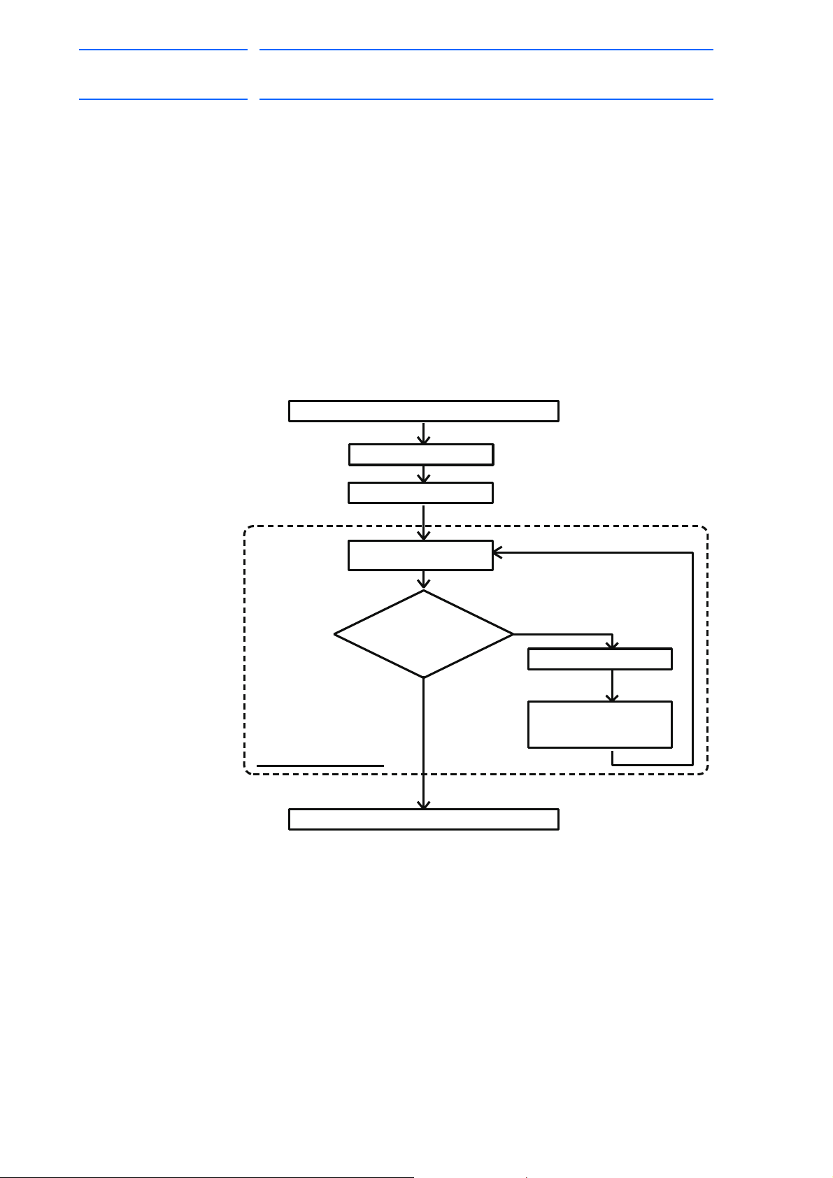
DX100 European
"OUT OF RANGE (ABSO DATA)" alarm occurs
Reset alarm
Turn ON servo power
Alarm occurs again
3, Correct defective axis
Replace PG system
Home position calibration
Playback possible
2,
Compare second home
position (check point)*
pulses with current
position pulses
Procedure After Alarm Occurs
NG
OK
1, Position confirmation
operation
Position checking point
92 of 764
Standard Maintenance
6.4.1 Purpose of Position Check Operation
171768-1CD
6 Operations After Replacing Parts
6.4 Setting the Second Home Position (Check Point)
If the absolute number of rotation detected at power supply ON does not
match the data stored in the absolute encoder the last time the power
supply was turned off, an alarm is issued when the controller power is
turned ON.
There are two possible causes of this alarm:
• Error in the PG system
• The manipulator was moved after the power supply was turned OFF.
If there is an error with the PG system, the manipulator may stall when
playback is started. If the absolute data allowable range error alarm has
occurred, playback and test runs will not function and the position must be
checked.
6-15
RE-CHO-A109
Page 93
171768-1CD
NOTE
93 of 764
DX100 European
Standard Maintenance
6 Operations After Replacing Parts
6.4 Setting the Second Home Position (Check Point)
1, Position Check
After the “OUT OF RANGE (ABSO DATA)” alarm occurs, move to the
second home position using the axis keys and perform the position
confirmation. Playback, test runs, and FWD operation will not function
unless “CONFIRM POSITION” is performed.
2, Pulse Difference Check
The pulse number at the second home position is compared with that at
the current position. If the difference is within the allowable range,
playback is enabled. If not, the alarm occurs again.
• The allowable range pulse is the number of pulses per rotation of the
motor (PPR data).
• The initial value of the second home position is the home position
(where all axes are at pulse 0). The second home position can be
changed. For details, refer to section 6.4.2 “Procedure for the
Second Home Position Setting (Check Point)” on page 6-17.
3, Alarm Occurrence
If the alarm occurs again, there may be an error in the PG system. Check
the system. After adjusting the erroneous axis, calibrate the home position
of the axis, then check the position again.
• Home position calibration of all the axes at the same
time enables playback operations without having to
check the position.
• Sometimes in a system with a manipulator that has no
brake, it is possible to enable playback without position
checking after the alarm occurs. However, as a
rule, always perform “CONFIRM POSITION”.
Under the above special conditions, the manipulator
moves as follows:
After starting, the manipulator moves at low speed (1/10 of
the maximum speed) to the step indicated by the cursor.
If it is stopped and restarted during this motion, the low
speed setting is retained until the step at cursor is reached.
Regardless of cycle setting, the manipulator stops after the
cursor step is reached.
Starting the manipulator again then moves it at the
programmed speed and cycle of the job.
6-16
RE-CHO-A109
Page 94

DX100 European
PAGE
GO BACK
PAGE
GO BACK
94 of 764
Standard Maintenance
6.4.2 Procedure for the Second Home Position Setting (Check Point)
171768-1CD
6 Operations After Replacing Parts
6.4 Setting the Second Home Position (Check Point)
Apart from the “home position” of the manipulator, the second home
position can be set up as a check point for absolute data. Use the
following steps to set the specified point.
If two or more manipulators or stations are controlled by one controller, the
second home position must be set for each manipulator or station.
1. Select {ROBOT} under the main menu.
2. Select {SECOND HOME POS}.
– The SECOND HOME POS window appears.
Th
e message “Available to move to and modify specified point” is
shown.
3. Press the page key ,
or select “PAGE” to display the selection
window for the control group.
– The group axes by which the second home position is set is
sele
cted when there are two or more group axes.
4. Press the axis keys.
– Move the manipulator to the new second home position.
5. Press [MODIFY] and [ENTER].
– The second home position is changed.
6-17
RE-CHO-A109
Page 95
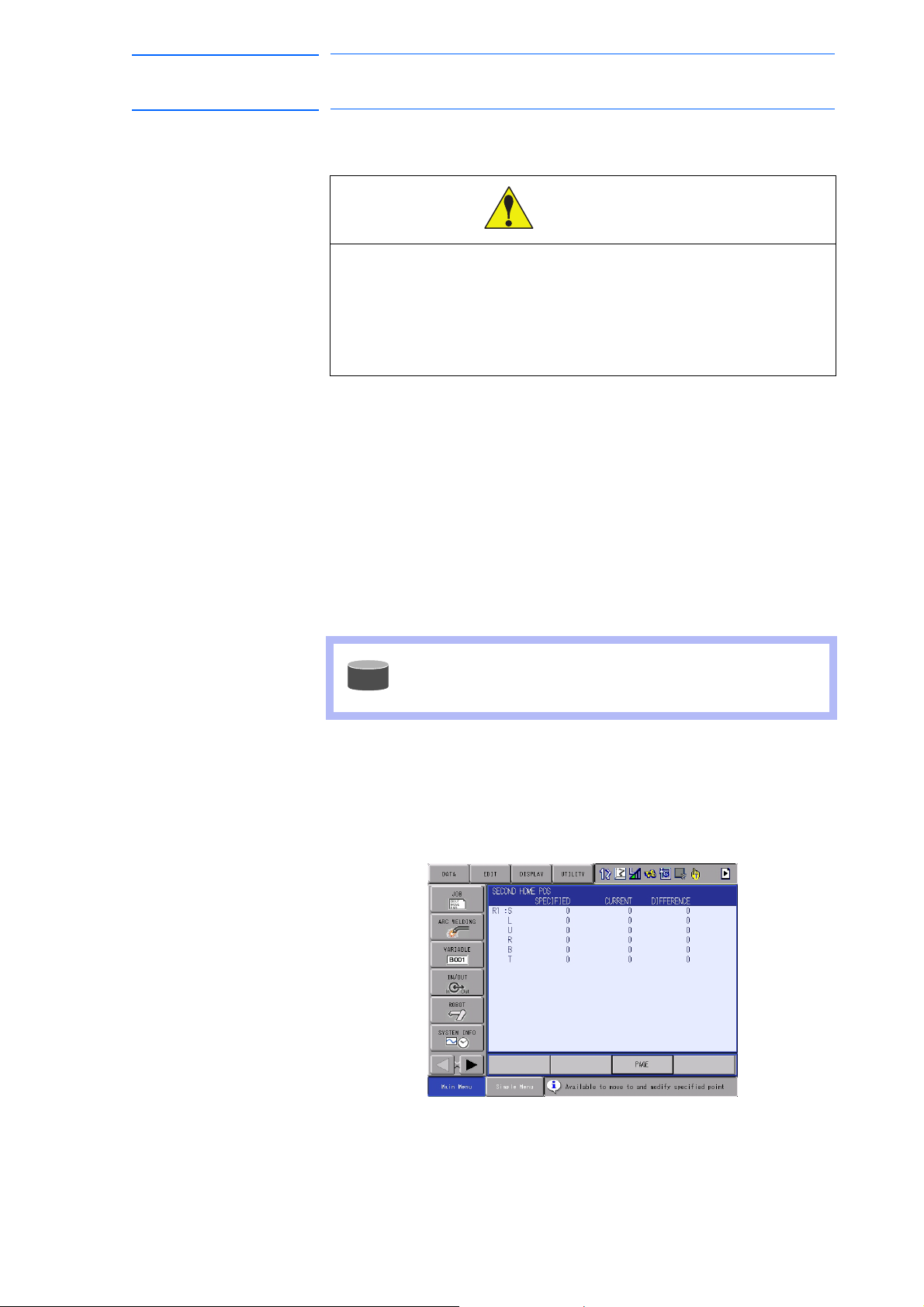
171768-1CD
WARNING
SUPPLE-
MENT
95 of 764
DX100 European
Standard Maintenance
6 Operations After Replacing Parts
6.4 Setting the Second Home Position (Check Point)
6.4.3 Procedure after the Alarm
• Be aware of safety hazards when performing the position
confirmation of the specified point.
Abnormality of the PG system may be cause for alarm. The
manipulator may operate in an unexpected manner, and there is
a risk of damage to equipment or injury to personnel.
If the "OUT OF RANGE (ABSO DATA)" alarm occurs, perform the
followings
• Reset the alarm
• Turn Servo power ON
and confirm the second home position. After the confirmation, if the PG
system is found to be the cause of the alarm, perform the necessary
operation, such as replacing the PG, etc.
The robot current position data when turning main power supply OFF and
ON can be confirmed in “POWER ON/OFF POS" window.
Refer to section 7.7 “Position Data When Power is
Turned ON/OFF” on page 7-21 for details on the
“POWER ON/OFF POS" window.
1. Select {ROBOT} under the main menu.
2. Select {SECOND HOME POS}.
– The SECOND HOME POS window appears.
6-18
RE-CHO-A109
Page 96
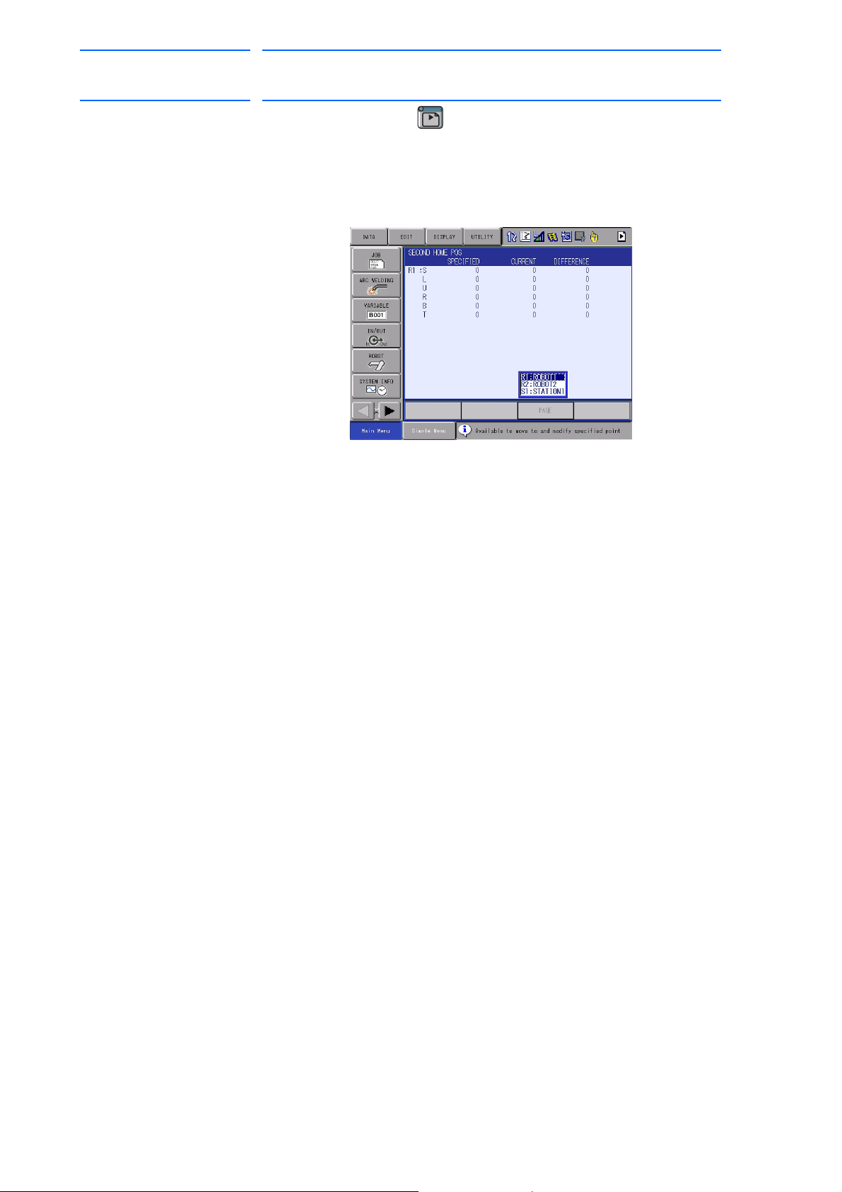
DX100 European
PAGE
GO BACK
PAGE
GO BACK
96 of 764
Standard Maintenance
171768-1CD
6 Operations After Replacing Parts
6.4 Setting the Second Home Position (Check Point)
3. Press the page key .
or select "PAGE" to display the selectio
n window for the control group.
– The group axes by which the second home position is set is
selected when there are two or more group axes.
4. Press [FWD].
– TCP moves to the second home position. The robot moving speed is
set as
selected manual speed.
5. Select {DATA} under the menu.
6. Select {CONFIRM POSITION}.
– The message “Home position checked” is shown.
Pulse da
ta of the second home position and current pulse data are
compared. If the compared error is in allowed range, playback
operation can be done.
If the error is beyond the allowed range, the alarm occurs again.
6-19
RE-CHO-A109
Page 97
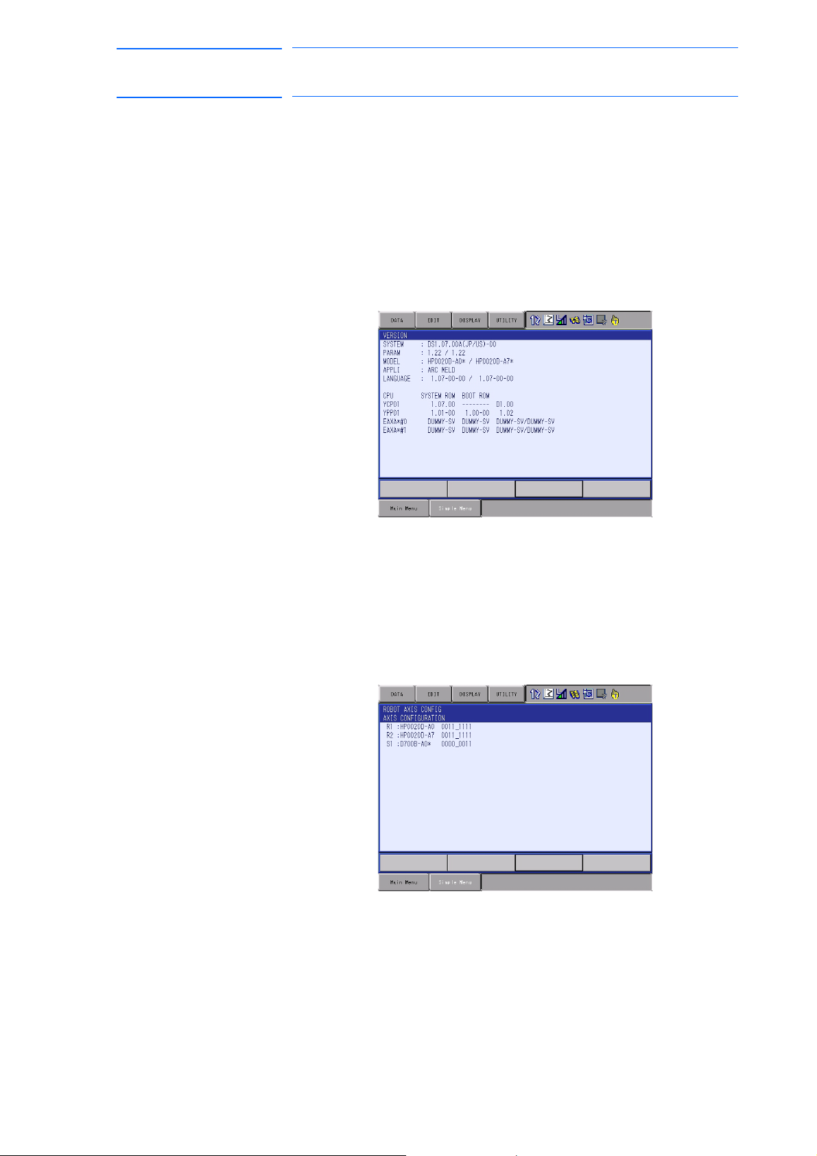
171768-1CD
97 of 764
DX100 European
Standard Maintenance
7 System Diagnosis
7.1 System Version
7 System Diagnosis
7.1 System Version
It is possible to check the system CPU version information as follows.
1. Select {SYSTEM INFO} under the main menu.
2. Select {VERSION}.
– The VERSION window appears.
7.2 Manipulator Model
1. Select {ROBOT} under the main menu.
2. Select {MANIPULATOR TYPE}.
– The ROBOT AXIS CONFIG window appears.
7-1
RE-CHO-A109
Page 98

DX100 European
98 of 764
Standard Maintenance
7 System Diagnosis
7.3 Input/Output Status
7.3 Input/Output Status
7.3.1 Universal Input
The status of input signal which is referred to by input instruction of a job
can be confirmed.
7.3.1.1 Universal Input Window
1. Select {IN/OUT} under the main menu.
2. Select {UNIVERSAL INPUT}.
171768-1CD
– The UNIVERSAL INPU
7.3.1.2 Universal Input Simple Window
1. Select {IN/OUT} under the main menu.
2. Select {UNIVERSAL INPUT}.
– The UNIVERSAL INPUT window appears.
3. Select {SIMPLE} from the pull-down menu of {DISPLAY}.
T window appears.
– The UNIVERSAL INPUT simple window appears.
7-2
RE-CHO-A109
Page 99
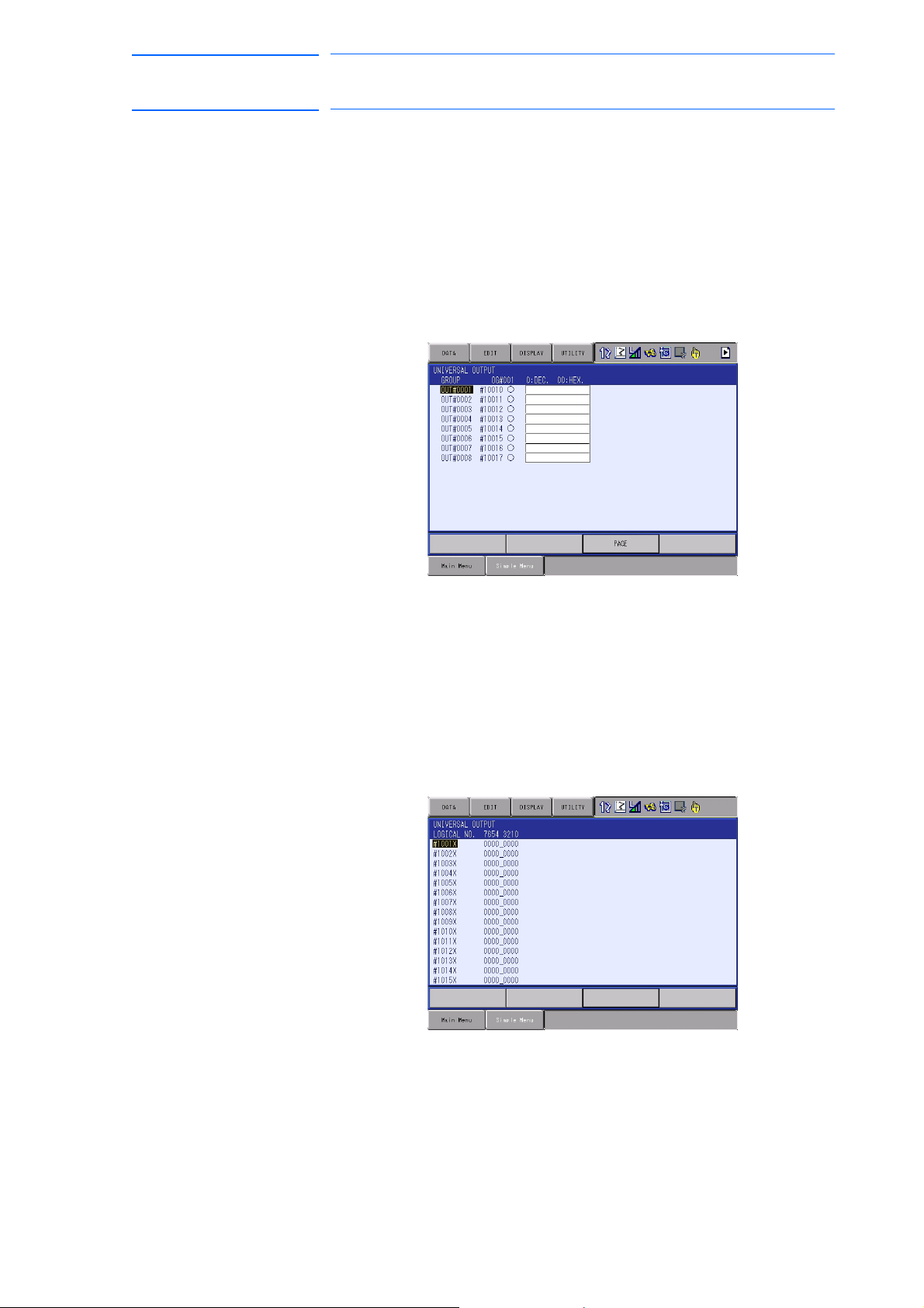
171768-1CD
99 of 764
DX100 European
Standard Maintenance
7.3.2 Universal Output
7.3.2.1 Universal Output Window
7 System Diagnosis
7.3 Input/Output Status
The status of the output signal set by the output instruction can be
confirmed and modified.
1. Select {IN/OUT} under the main menu.
2. Select {UNIVERSAL OUTPUT}.
– The UNIVERSAL OUTPUT window appears.
7.3.2.2
Universal Output Simple Window
1. Select {IN/OUT} under the main menu.
2. Select {UNIVERSAL OUTPUT}.
– The UNIVERSAL OUTPUT window appears.
3. Select {SIMPLE} from the pull-down menu of {DISPLAY}.
– The UNIVERSAL OUTPUT simple window appears.
7-3
RE-CHO-A109
Page 100

DX100 European
NOTE
100 of 764
Standard Maintenance
7.3.2.3 Modifying the Output Status
7 System Diagnosis
7.3 Input/Output Status
The status of universal output signal can be changed by the operation
below.
1. Select the desired output signal number.
171768-1CD
– Select the status of
UNIVERSAL OUTPUT window.
2. Press [INTER LOCK] + [SELECT].
– The status is changed. (: ON status, : OFF status)
The status of universal output signal can be changed only
when the mode is set to the teach mode.
the desired output signal, “” or “” in the
7-4
RE-CHO-A109
 Loading...