

Page 1
DSD 406 / DSD 412
Technical Manual
MagneTek
Page 2

a
3/21/96
© 1996 by
MagneTek, Inc.
New Berlin, Wisconsin
All rights reserved. No part of this publication may be reproduced or used in any form by any means – graphic, electronic, or
mechanical, including photocopying, recording, taping, or information storage and retrieval systems – without written
permission of the publisher.
MicroTrac, DSD, PAC and MagneTek are trademarks of MagneTek, Inc.
The following table shows all pages that have been revised since the first issue
of this manual.
Revision Affected Pages
Date
4/15/94 Initial
3/21/96 Overall revision
Revision
History
Related
Documents List
The following publications provide additional information on the DSD 406 / 412
drives. Each is available from MagneTek.
● PCDU Guide TM 6305
Additional copies of this manual can also be ordered by specifying the
DSD 406 / 412 Product Guide (TM 6107).
Page 3

Warranty
i
Warranty
3/21/96
Warranty
Standard products manufactured by MagneTek are warranted to be free from
defects in workmanship and material for a period of one year from date of
shipment and any products which are defective in workmanship or material will
be repaired or replaced, at MagneTek's option, at no charge to the Buyer. Final
determination as to whether a product is actually defective rests with MagneTek.
The obligation of MagneTek hereunder shall be limited solely to repair or
replace, at MagneTek's discretion, products that fall within the foregoing
limitations, and shall be conditioned upon receipt by MagneTek of written notice
of any alleged defects or deficiency promptly after discovery and within the
warranty period, and in the case of components or units purchased by
MagneTek, the obligations of MagneTek shall not exceed the settlement that
MagneTek is able to obtain from the supplier thereof. No products shall be
returned to MagneTek without its prior consent. Products which MagneTek
consents to have returned shall be shipped prepaid f.o.b. MagneTek's factory .
MagneTek cannot assume responsibility or accept invoices for unauthorized
repairs to its components, even though defective. The life of the products of
MagneTek depends, to a large extent, upon the usage thereof, and MAGNETEK
MAKES NO WARRANTY AS TO FITNESS OF ITS PRODUCTS FOR THE
SPECIFIC APPLICATIONS BY THE BUYER NOR AS TO PERIOD OF
SERVICE UNLESS MAGNETEK SPECIFICALLY AGREES OTHERWISE
IN WRITING AFTER THE PROPOSED USAGE HAS BEEN MADE
KNOWN TO IT.
THE FOREGOING WARRANTY IS EXCLUSIVE AND IN LIEU OF ALL
OTHER WARRANTIES, EXPRESSED OR IMPLIED, INCLUDING, BUT
NOT LIMITED TO, ANY WARRANTY OF MERCHANTABILITY OR OF
FITNESS FOR A PARTICULAR PURPOSE AND BUYER HEREBY
WAIVES ANY AND ALL CLAIMS THEREFORE.
IN NO EVENT SHALL MAGNETEK BE LIABLE FOR LOSS OF PROFIT,
INDIRECT, CONSEQUENTIAL OR INCIDENTAL DAMAGES WHETHER
ARISING OUT OF WARRANTY, BREACH OF CONTRACT OR TOR T.
Limitation
of Liability
Page 4

Manual Contents
ii
Table of Contents
3/21/96
Table of
Contents
Page
Introduction ........................................................................................................ 1
How To Use This Manual ............................................................................. 1
Controls and Indicators ................................................................................. 1
Safety Statements .......................................................................................... 2
How To Contact MagneTek .......................................................................... 2
DSD Drive Description ................................................................................. 3
System Considerations .................................................................................. 5
Installation and Start-Up .................................................................................. 9
Pre-Installation Considerations ..................................................................... 9
Physical Installation ...................................................................................... 9
Electrical Hook-Up ..................................................................................... 14
Use of An Analog Tachometer ................................................................... 20
Pre-Power Check ......................................................................................... 20
Drive Start-Up ............................................................................................. 21
Operation .......................................................................................................... 23
Controls and Indicators ............................................................................... 23
Start-Up Operation ...................................................................................... 25
General Operation........................................................................................ 26
Parameter Functions .................................................................................... 28
Monitor Functions ....................................................................................... 30
Upload/Download of Program/Parameters ................................................. 31
Upload/Download Introduction and Definitions......................................... 31
General Upload/Download Procedures....................................................... 33
Error Handling/Reporting ........................................................................... 45
Non-Volatile “Ram”-Access ....................................................................... 51
Load Defaults Function ............................................................................... 53
Self-Tune (PCU Parameter Measurement) ................................................. 54
Maintenance ..................................................................................................... 57
Preventive Maintenance .............................................................................. 57
Power Conversion Unit Diagnostics............................................................ 58
Troubleshooting Guide................................................................................. 61
Replacing Fuse(s)......................................................................................... 77
Replacing DSD Drive Control PCB............................................................ 79
Replacing the Fan......................................................................................... 81
Replacing the Power Supply........................................................................ 85
Replacing the DSD Armature Interface PCB.............................................. 87
Spare Parts List ............................................................................................... 89
Glossary ............................................................................................................ 95
Index .............................................................................................................. 104
Page 5

List of Tables
Table
Number Title Page
1 Drive Ratings and Specifications.................................................... 5
2 # Function Code Descriptions........................................................ 27
3 Troubleshooting Guide .................................................................. 61
4 Connectors on Drive Control PCB................................................. 79
5 230 Volt Drives Spare Parts............................................................ 89
6 460 Volt Drives Spare Parts ........................................................... 91
7 Burden Resistor .............................................................................. 93
8 Power Range Resistor..................................................................... 94
Manual Contents
iii
List of Illustrations
3/21/96
List of
Illustrations
Figure
Number Title Page
1 Typical MicroTrac DSD System Diagram..................................... 7
2 Dimensions and Mounting Holes
DSD 406/412 1-60 Hp Versions..................................................... 10
3 Dimensions and Mounting Holes
DSD 406/412 75-125 Hp Versions................................................. 11
3.1 Dimensions and Mounting Holes
DSD 412 150-200 Hp Versions...................................................... 13
4 Shield Sheath Termination ............................................................ 16
5 Basic Connections for DSD Power Cube –
Ratings up to 206 Amps................................................................. 17
6 Connections to TB3 and TB1 DSD Power Cube –
Ratings up to 206 Amps................................................................. 18
7 Grounding of Multiple Units.......................................................... 19
8 Operator Controls and Indicators................................................... 23
9 DSD 406/412 to IBM PC Compatible Comp. Inter. Diagram...... 31
10 DSD Drive Fuse Replacement....................................................... 76
11 DSD Drive Control PCB................................................................ 78
12 Replacing DSD Fan........................................................................ 66
13 DSD Power Supply Replacement.................................................. 84
14 DSD Armature Interface PCB Replacement ................................. 86
Page 6

1
Introduction
1
How To Use This Manual
3/21/96
MagneTek has made this product guide an easy to use reference. To help you
use this manual, we have provided the following guides:
● The top of each page has an identification of the section. For example, notice
that at the top of this page appears. This identifies
the page as part of Section 1, Introduction. There are four sections in this
manual: Introduction, Installation and Start-Up, Operation and Maintenance.
● Each section is organized into one or more major subject headings. These are
the main topics covered in that section. You will recognize major subject
headings by their distinctive appearances. The next line illustrates an
example:
This is an example of a major subject heading from Section 3.
Each major subject heading may have one or more minor topics that are
covered. The next line illustrates an example:
This is a minor topic covered under “Controls and Indicators.”
Each minor topic may have one or more descriptive headings. These identify
items covered within the minor topic. The next line illustrates an example:
This is a descriptive heading covered under “Status LEDs.”
At the bottom of each page is the name of the first major subject heading
covered on that page. The page number and revision date are also included.
For example, at the bottom of this page, the information indicates that “How
to Use This Manual” is the first major subject heading. The revision date
indicates the last date the page was changed in any way .
Using the information on the top of the page to find the section, the bottom of
the page to find the major subject heading and the left margin to find the
minor topics and descriptive headings, you can easily page through the
manual to find the information you need.
A table of contents and index are also included. The Table of Contents can be
used to locate sections and major topics. The Index is helpful in locating
specific terms or topics. A glossary is provided to define terms which may be
unfamiliar.
How To Use
This Manual
Controls and
Indicators
Status LEDs
Ready
1
Introduction
Page 7

1
Introduction
2
Safety Statements
3/21/96
Safety
Statements
How To Contact
MagneTek
In addition to notes, the following types of precautionary statements appear in
this manual.
IMPORTANT
A statement of conditions which should be observed during drive
setup or operation to ensure dependable service.
CAUTION
A statement of conditions which must be observed to prevent
undesired equipment faults or degraded drive system
performance.
WARNING
A statement of conditions which MUST BE OBSERVED to
prevent personal injury or serious equipment damage.
For additional information, contact any MagneTek Representative, or
Authorized Distributor, or contact the DSD Technical Support Staff at:
MagneTek, Inc.
16555 West Ryerson Road
New Berlin, WI 53151
(800) 541-0939 (414) 782-0200
FAX: (414) 782-1283
Page 8

1
Introduction
3
DSD Drive Description
3/21/96
DSD Drive
Description
Regeneration
Capability
Flexibility
Control
Accuracy
The MicroTrac®DSD is a complete digital system drive which provides
individual drive and system control in one compact package. This manual
describes two basic configurations, the DSD 406 (6SCR) Nonregenerative and
the DSD 412 (12SCR) Regenerative. All descriptions pertain to both
configurations unless specifically noted.
The nature of an electric motor is such that, if more torque is applied to the
motor by the load than is applied to the load by the motor, the motor will act as
an electrical generator, producing an electrical current. This phenomenon, called
regeneration, occurs anytime the speed of the motor is above the reference (or
preset) speed, sometimes referred to as an “overhauling load” condition. A
regenerative drive, such as the DSD 412, has the capability to feed the electrical
power generated by the motor back into the supply mains. Also referred to as
four-quadrant operation, it is this capability which requires that the DSD 412
contain a total of 12 SCRs, rather than the six included in the two-quadrant,
Nonregenerative DSD 406.
The drive uses two microprocessors, one for the Power Conversion Unit
circuitry , one for the Drive Control Unit circuitry, and is totally software
configurable to the application through a high level language. This provides
complete flexibility without having to make hardware adjustments. Interface to
other equipment is provided with Local Input/Output (I/O) or a high speed Local
Area Network. Use of the MicroTrac Local Area Network (LAN) means that a
single coaxial cable eliminates multiple conductor cables and provides high
noise immunity .
Extensive diagnostics and setup capability are provided through two
Control/Display Units. The Standard Control/Display Unit (SCDU) is mounted
on the Drive Control PCB and consists of a 4-1/2 digit numeric LED display ,
four push buttons and LEDs. The SCDU can be used for all setup functions and
many diagnostics. The Portable Control/Display Unit (PCDU) is an optional
hand-held device that can be plugged into any DSD drive and used for all the
same functions as the SCDU plus some advanced diagnostics. The PCDU has
two lines of sixteen alphanumeric characters and a thirty-key keypad.
The distributed control architecture of the DSD systems means that each drive
performs its own regulation calculations synchronized to a common high
accuracy crystal master. Thus even minute crystal drift will not affect multiple
drive tracking. This allows a DSD system to maintain the drift between sections
at 0.00% steady state. The fully digital nature of the regulation means that an
individual drive can maintain a 0.00% average difference between set and actual
speed from no-load to full-load when using digital tachometer speed feedback.
Digital setup and performance assure exact process line and finished product
duplication shift to shift and month to month.
Page 9

1
Introduction
4
DSD Drive Description
3/21/96
Useability
Characteristics
Speeds, tensions, ratios, draws, limits, ranges, alarms, and other control
parameters can be set as percentages or exact numerical values. Parameters are
entered and displayed in common understandable units. The drive can be
completely setup prior to actual running and changes can be made during
operation. Keypad entry of changed parameters, protected memory , and factory
default values allow the operator to modify data with minimum risk to the
process.
The DSD is available for general use as a complete panel mounted enclosed
drive (NEMA 1 or NEMA 12).
Authorized system integrators can also purchase the drive as a power cube. The
power cube is designed for mounting in a cabinet; space allowances for air
circulation, additional components, outgoing terminals, and wire bends must be
provided.
The enclosed drive consists of the DSD power cube mounted on a panel with a
skirted NEMA 1 or NEMA 12 enclosure, with added fused control transformer
for 115V supply, armature loop contactor, and field wiring terminals. An input
circuit breaker with through-the-door operator is available as an option.
The DSD drive is designed to be connected to a three wire ungrounded power
system, or a four wire grounded or ungrounded power system.
All DSD drives are programmed using MagneTek's PAC language. The drive
programming consists of two portions; the standard control programs shared by
all DSD drives and the application specific programming which defines how the
drive operates in the particular application. The latter portion of DSD drive
programs are developed based on the PAC language, wherein different drive
functions are represented by interconnected graphical symbols, called PAC
blocks, much like an electronic schematic. This provides the ability to quickly
modify programs, along with an assurance of program repeatability and stability .
PAC Language
Programming
Page 10

Ratings Protective Features
● 3.3 - 206 Amps
● 3 Phase, 48-62 Hz
● 1.0 Service Factor
● 150% full load current for one
minute
● 200% full load current for 10
seconds
Basic Drive Specifications
● Full-wave six-pulse SCR control
● Regulation (of set speed) to
0.00% with digital tachometer
speed feedback
● Current regulated shunt field
● Capable of constant HP
operation (requires tachometer)
● Self-adapting to incoming line
power of 230 or 460 VAC.
Service Conditions
● Line voltage 230 or 460 Vac, 3
phase, ±10% of nominal setting
● 115 volt, 1 phase control power
from separate source
● Frequency 48-62 Hz
● Incoming line impedance range
2%-10% of rated
● Operating Temperature 0-45° C
(55° C max at DSD chassis)
● Altitude to 3300 feet above sea
level
● Relative Humidity 95%
(noncondensing)
1
Introduction
5
System Considerations
3/21/96
System
Considerations
In order to operate in a system application, the DSD drive may be used with
other MagneTek devices with which it will communicate by means of the
MicroTrac Local Area Network (LAN). Refer to Figure 1 for a typical DSD
System.
Each of the following remote devices (board or assembly) is described in detail
in a separate User Reference Sheet.
● Remote Display Controller LAN Node PCB (RDC) – This board provides
a means for the DSD system to have system operating parameters displayed
● Programmed memory protection
● Self-protected control power
supply
● Fast phase-back of current
before loop contactor opens
● Contact interlock for E-Stop
● I
2
t motor overload protection
● AC line current limiting fuses
● DC bus fuse (DSD 412 only)
● Instantaneous over-current
protection
● Phase loss protection
● Input line monitoring
● Phase sequence insensitive
● dv/dt protection (snubbers)
● 1400 Peak Reverse Voltage
thyristors
● Field current economizer and
loss protection
● Tachometer monitoring and loss
protection
● Heat sink thermostat
● Automatic test of power circuit
upon power-up
● Control power supply loss
detection
● Isolated I/O and grounded
electronics
Table 1. Drive Ratings and Specifications
Page 11

1
Introduction
6
3/21/96
System Considerations
at locations remote from the DSD drive. The RDC communicates with the
drive through the LAN. A single RDC can support up to 31 Remote Display
Units (RDUs). By means of a Portable Control/Display Unit (PCDU), the
RDC allows the selected display for each RDU to be changed at anytime.
● Remote Display Unit (RDU) – Designed for mounting in a panel cutout, the
RDU provides a two-line LED display (16 character alphanumeric, and 5-1/2
digit numeric). It constitutes a terminal with the information on its display
transmitted to it by a Remote Display Controller LAN Node PCB (RDC).
● Remote Keyboard Assembly – Designed for mounting on a panel with or
near a Remote Display Unit (RDU), the Remote Keyboard allows initiation
of RDU display changes without the need for a Portable Control/Display
Unit (PCDU) plugged into the Remote Display Controller LAN Node PCB
(RDC).
● Remote I/O [Input/Output] Controller LAN Node PCB (RIO) – This
board provides a means for the DSD system to have inputs or outputs at
locations remote from the DSD drive. The RIO communicates with the
drive through the LAN. A single RIO can support up to 6 Remote I/O
boards, using any combination of the following three available types.
● Remote Logic I/O PCB (LOGIO) – This board provides isolated and non
isolated remote logic signal input/output capability for the DSD system. It is
connected to a Remote I/O Controller LAN Node PCB (RIO) for
communication with the DSD drive.
● Remote Analog I/O PCB (ANIO) – This board provides isolated and non
isolated remote analog signal input/output capability for the DSD system. It
is connected to a Remote I/O Controller LAN Node PCB (RIO) for
communication with the DSD drive.
● Remote Thumbwheel Switch I/O PCB (TWIO) – This board provides
remote thumbwheel switch input/output capability for the DSD system. It
can support up to 9 Thumbwheel Switch Assemblies. This board is
connected to a Remote I/O Controller LAN Node PCB (RIO) for
communication with the DSD drive.
● Remote Programmable Logic Controller (PLC) Interface – Available for
PLCs from many major manufacturers. It allows bi-directional
communication via the MicroTrac LAN between DSD drives and the PLC.
Both logic and numeric data can be transferred.
● Remote Power Supply – The Remote Power Supply produces control level
voltages for use by a Remote LAN Node PCB or a Remote Display Unit.
● Remote Serial Communication Controller LAN Node PCB (RSC) – This
board provides a means for the DSD system to have input from or output to
other equipment that uses RS-232 serial communication. The RSC
communicates with the DSD drive through the LAN.
Page 12

1
Introduction
7
3/21/96
System Considerations
Figure 1. Typical MicroTrac DSD System Diagram
MicroTrac
Drive
DRIVE
CONTROL
UNIT
93 Ohm
Terminator
93 Ohm
Terminator
INPUT/OUTPUT
REMOTE
CONTROLLER
PCB (RIO)
MicroTrac
Drive
DRIVE
CONTROL
LOCAL
I/O
PROGRAMMABLE
LOGIC
CONTROLLER (PLC)
UNIT
REMOTE
PLC
INTERFACE
LOCAL
I/O
RG 62/U Coaxial Cable
2.5 million bits/second
REMOTE
COMMUNICATIONS
CONTROLLER
PCB (RSC)
MicroTrac
CONTROL
RS-232
Drive
DRIVE
UNIT
LOCAL
I/O
REMOTE
DISPLAY
CONTROLLER
PCB (RDC)
RS-485
PCDU
DISPLAY #1
8 ISOLATED LOGIC
REMOTE
LOGIC
INPUT/OUTPUT
PCB
(LOGIO)
REMOTE
ANALOG
INPUT/OUTPUT
PCB
(ANIO)
REMOTE
THUMBWHEEL
INPUT/OUTPUT
PCB
(TWIO)
UP TO 6 REMOTE INPUT/OUTPUT PCBS
I/O MODULES
7 NON-ISOLATED
LOGIC OUTPUTS
16 NON-ISOLATED
LOGIC INPUTS
2 NON-ISOLATED
ANALOG OUTPUTS
4 ISOLATED ANALOG
I/O MODULES
4 NON-ISOLATED
ANALOG OUTPUTS
4 NON-ISOLATED
ANALOG INPUTS
PERSONAL
COMPUTER
UP TO 9 BANKS OF
6 DIGITS
+188888
8 8 8 8 8 8
+188888
THUMB
WHEELS
UP TO 31 REMOTE
DISPLAY UNITS
REMOTE
DISPLAY
UNIT (RDU)
DISPLAY #2
MESSAGE
DISPLAY #3
DISPLAY #4
KEYBOARD
123DC
456DN
7
89
+
-
•
0
NE
KEYBOARD
SELECT
ENABLE
LA-8
Page 13

2
Installation and Start-Up
9
3/21/96
Pre-Installation Considerations
Pre-Installation
Considerations
Receipt of
Shipment
Unpacking
Re-Packing
Physical
Installation
The “Installation and Start-Up” section describes and illustrates the following:
● How to select the site to install your DSD drive.
● How to mount your DSD drive.
● How to connect your DSD drive to incoming power and the motor .
● How to start-up the system after it is installed.
The DSD drive is air cooled. The lowest HP rated units are cooled by
convection; all other units are equipped with a fan to ensure adequate air flow .
Select a site for installing the drive which is clean and well ventilated.
Maintenance will be minimized if the drive is located in a clean atmosphere. The
standard drive is designed for vertical mounting.
All equipment is fully tested at the factory . Any damage or shortages evident
when the equipment is received must be reported immediately to the commercial
carrier who transported the equipment. Assistance, if required, is available from
your MagneTek representative. Always refer to the order number, equipment
description, and serial number when contacting MagneTek.
For long periods of storage, equipment should be covered to prevent corrosion
and should be placed in a clean, dry location. If possible, equipment should be
stored in its original crating. Periodic inspection should be made to ensure that
the equipment is dry and that no condensation has accumulated. The equipment
warranty does not cover damage due to improper storage.
Remove the protective shipping material from around the equipment. Remove
all packing material. Unbolt the equipment from its crate. Inspect for loose
wiring. Make sure that all contact wedges and other shipping devices have been
removed.
The drive should be bolted in a crate which provides at least 2 inches clearance.
The drive should then be wrapped in polyethylene and covered with wax
impregnated double walled # 350 corrugation and crated. Assistance, if
required, is available from your MagneTek representative.
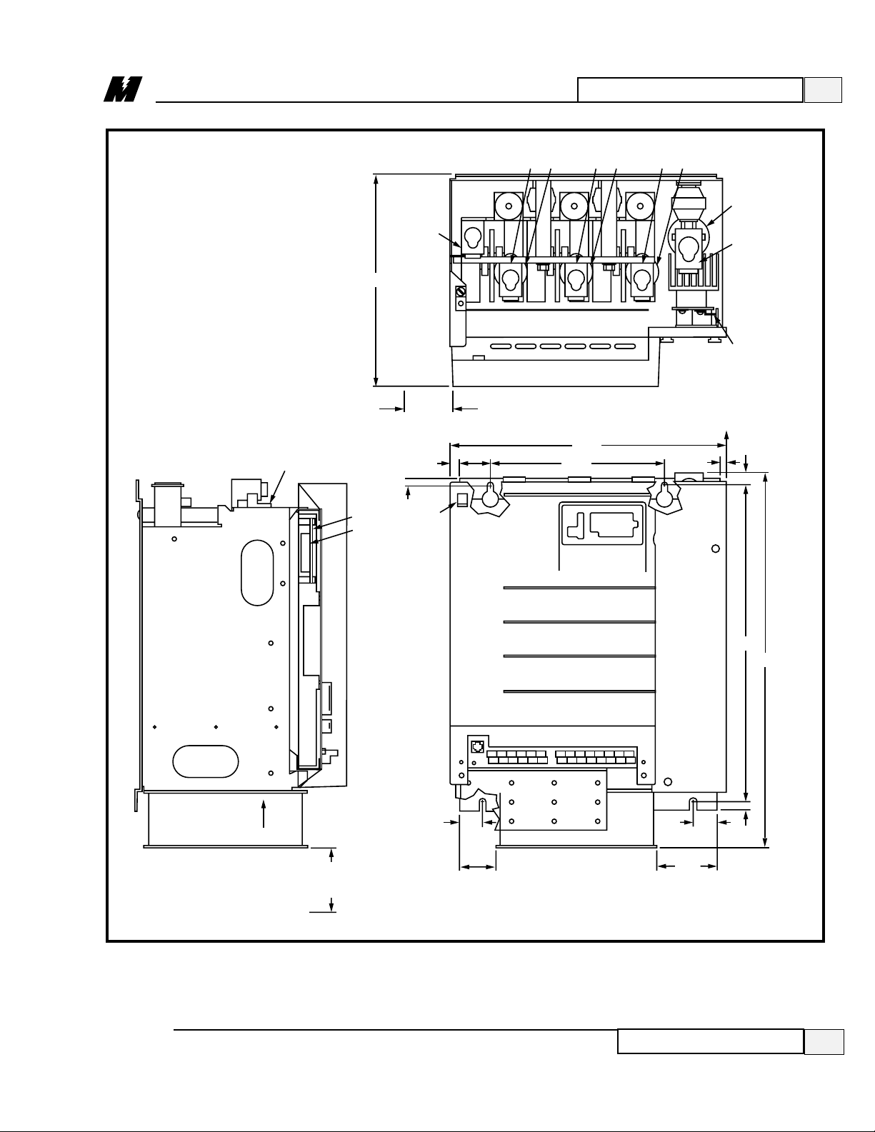
Attach the drive to a cabinet panel or other vertical structure using the mounting
holes provided at the back of the drive (refer to Figure 2, 3 or 3.1 for dimensions
and mounting hole locations). Allow six inches top and bottom and two inches
at sides for free air circulation. For either style, hinged door swing-out clearance
is the same as the width dimension. Ensure that the unit is level.
Storage
CAUTION
The DSD Drive Control PCB has electrostatic sensitive
components. You must follow Electrostatic Discharge (ESD)
procedures to protect the components.
Page 14

4/15/94
2
Installation and Start-Up
10
Physical Installation
Figure 2. Dimensions and Mounting Holes
DSD 406/412
1-60 Hp Versions
MIN. DOOR
SWING
CLEARANCE
2.00
(APPROX. 6.75"
ABOVE MTG. SURFACE)
9.75
0.50
0.31
12.25
11.25
ARM.
NEG.
GND.
L3
L2
L1
NEG GND L1 L2 L3 POS
ARM.
POS.
0.31
FAN (WHEN SUPPLIED)
AIR
FLOW
A4
TB3
MOTOR
FIELD
CONNECTIONS
8
7
6
5
4
3
2
1
TB3
8
7
6
5
4
3
2
1
S3
J3
17.12
19.87
A1
TB1
TB4
2.44
J2
TB1
TB4
F2(–)
FAN (WHEN SUPPLIED)
11.25
3" MINIMUM CLEARANCE REQUIRED
0.50
LA-4
Page 15

2
Installation and Start-Up
11
Physical Installation
3/21/96
Figure 3. Dimensions and Mounting Holes
DSD 406/412
75 - 125 Hp Versions
0.31
GND
A4
TB3
MIN. DOOR SWING
WITH MATING DB9
CONNECTOR IN J1
8
7
6
5
4
3
2
1
J3
21.06
GND
2.69
0.38
0.94
18.06
F1 F2 F3 F4
12.00
11.25
ARM (–) L1 L2 L3
GND
TB3
8
7
6
5
4
3
2
1
11.00
13.06
0.44
ARM (+)
S3
FAN
AIR FLOW
13.88
A1
J2
TB1
TB4
FAN
MOTOR FIELD
CONNECTIONS
0.31
A3
0.38
4.00
ALLOW APPROX. 4" BELOW FAN FOR SERVICING
OF FAN, AND UNRESTRICTED AIR INTAKE.
AC1
07
0.38
1.25
LA-4A
Page 16

2
Installation and Start-Up
12
Physical Installation
3/21/96
Page 17
2
Installation and Start-Up
13
Physical Installation
3/21/96
Figure 3.1. Dimensions and Mounting Holes
DSD 412
150-200 Hp Versions
4.00 MINIMUM
CLEARANCE
REQUIRED
AIR FLOW
1.94
2.13
FAN
FAN
3.50
1.69
23.49
19.50
0.50
A4
TB3
17.09
10.75
0.505
0.83
12.50 MIN.
WIRE BEND
ALLOWANCE
1.94
0.58
2.38 MIN.
DOOR SWING
0.438
12.93
GND
ARM (–)
GND
UNPLUG TB3
FROM HEADER
WHILE
INSTALLING
WIRES.
LA-100
TB1
A1
J2
8
7
6
5
4
3
2
1
(TERMINAL BLOCK QTY PER DRIVE SPECIFICATION)
L1 F1 L2 F2 L3 F3
F4
ARM(+)
MOTOR
FIELD
CONNECTIONS
GND
Page 18

2
Installation and Start-Up
14
Electrical Hook-Up
3/21/96
Ensure that wire size and disconnect devices conform to the installation
contractor’s drawings and to all applicable codes.
● Although the three phase input power line is fuse protected internal to the
drive, it is recommended to provide branch circuit protection by means of a
circuit breaker in accordance with the National Electrical Code, local codes
and with a rating of not less than 5,000 rms Symmetrical Amperes and 600
Volts for 2 to 25 Hp rated drives or 10,000 rms Symmetrical Amperes and
600 volts for 30 to 60 Hp rated drives.
● Electronic overload protection is provided as part of the standard DSD
product. It si electronically timed and will shut down the drive along a
time/output current curve which provides shutdown at 60 seconds at 150%
or 10 seconds at 200% of rated output current. An overload relay may be
added external to the drive in accordance with the National Electrical Code
and local codes for additional protection.
● Main Circuit Input/Output Wire Sizing:
L1-3
: Using 600V vinyl-sheathed wire per the following table.
Electrical
Hook-Up
Recommended Wire Gauge (Copper Only)
Torque
Drive Hp
60°C 75°C
(in-lbs)
214 1435
314 1435
514 1435
7 8 10 40 - 35 *
10 8 10 40 - 35 *
15 6 8 45 - 40 *
20 6 8 45 - 40 *
25 4 4 45
30 4 4 45
40 1 150
50 1 150
60 1/0 180
75 3/0 250
100 3/0 250
125 250 MCM 325
150 600 MCM 375
200 600 MCM 375
* Torque per wire gauge.
Page 19

2
Installation and Start-Up
15
Electrical Hook-Up
3/21/96
ARM (–): Using 600V vinyl-sheathed wire per the following table.
ARM (+): Using 600V vinyl-sheathed wire per the following table.
● Field Current Wire Sizing: The recommended conductor for field current
ratings between 10.0 Ampere and 16.0 Ampere is 12 AWG. The
recommended conductor for field current ratings below 10.0 AMpere is 14
AWG. use 600 V vinyl-sheathed 105°C wire or equivalent. The
recommended torques on the field lugs for 14-10 AWG is 25 in-lbs.
Recommended Wire Gauge (Copper Only)
Torque
Drive Hp
60°C 75°C 90°C
(in-lbs)
214 14 35
314 14 35
514 14 35
7 6 8 45 - 40 *
10 6 8 45 - 40 *
15 4 4 45
20 4 4 45
25 3 50
30 3 50
40 1/0 50
50 1/0 50
60 3/0 50
75 250 MCM 325
100 250 MCM 325
125 350 MCM 325
150 500 MCM 375
200 750 MCM 375
* Torque per wire gauge.
Recommended Wire Gauge (Copper Only)
Torque
Drive Hp
60°C 75°C 90°C
(in-lbs)
214 14 35
314 14 35
514 14 35
7 6 8 45 - 40 *
10 6 8 45 - 40 *
15 4 4 45
20 4 4 45
25 3 50
30 3 50
40 1/0 180
50 1/0 180
60 3/0 250
75 250 MCM 325
100 250 MCM 325
125 350 MCM 325
150 500 MCM 375
200 700 MCM 375
* Torque per wire gauge.
Page 20

2
Installation and Start-Up
16
Electrical Hook-Up
3/21/96
● If the DSD drive is being used in a system application, use a BNC "T"
connector to connect LAN (Local Area Network) coaxial cable to J3 on the
DSD Drive Control PCB.
● The coaxial cable must ultimately be terminated at both ends by a 93 ohm
termination resistor. (MagneTek part number 05P00034-0586)
Figure 4. Shield Sheath Termination
● GND: Recommended conductor size, 2 AWG 600 V vinyl-sheathed for
COPPER wire, 1/0 AWG 600 V vinyl-sheathed for ALUMINUM OR
COPPER CLAD ALUMINUM wire. Recommended torque on the GND
lug is 50 in-lbs.
● Control Wire Sizing:
TB1
: Recommended conductor size, 22-18 AWG 300 V 105°C
vinyl-sheathed wire. Recommended torque is 3.4 in-lbs.
TB3
: Recommended conductor size, < 12 AWG 300 V 105°C
vinyl-sheathed wire. Recommended torque is 5 in-lbs.
TB1
: Recommended conductor size, 14 AWG 300 V 105°C
vinyl-sheathed wire. Recommended torque is 3.4 in-lbs.
Observe the following when wiring:
● Separate the leads used for speed reference, feedback, and other low level
signals from those used for the motor armature, field and AC power.
Do not run these two groups in the same conduit or wire trough.
● Provide shielded and twisted leads as indicated on the Schematic and/or
Interconnection Diagrams. Connect all shields on shielded wire to system
common (not ground) on one end only . Twisted shielded pair wire should be
used for long runs. (Refer to Figure 4 for proper cable preparation.)
SHIELD SHEATH
OUTER JACKET
TO DSD
406/412
SIGNAL
TERMINALS
TO SHIELD
SHEATH
TERMINAL
CRIMP
CONNECTION
WRAP BOTH ENDS
OF SHEATH WITH
INSULATING TAPE
DO NOT
CONNECT
TO
EXTERNAL
CIRCUIT
LA-9
Page 21

2
Installation and Start-Up
17
Electrical Hook-Up
3/21/96
For a NEMA 1 or open panel mounted drive, refer to the equipment
Interconnection Diagram for detailed wiring information.
If only a power cube was ordered, the following connections need to be made
(refer to Figures 5 and 6 for location of terminating points on drives rated up to
330 Amps):
❏ On units rated at 206A armature current (206A Iarm) or less, connect the
three phases of the line from the load side of the isolation transformer or
input circuit breaker to fuses F1, F2, and F3 (marked L1, L2, and L3).
(Refer to Figure 5.) Phase rotation is not important.
Figure 5. Basic Connections for DSD Power Cube –
Ratings up to 206 Amps
WARNING
The external COAST STOP circuit shown on the
Schematic Diagram MUST BE WIRED to the drive as a
safety consideration in case of microprocessor failure.
3 PHASE 230-460 VAC INPUT POWER
FROM CIRCUIT BREAKER OR
ISOLATION TRANSFORMER.
PHASE ROTATION IS NOT IMPORTANT
GND
NEG
L1 L2 L3 POS
F2F1 F3
F4
(DSD
412
ONLY)
K1
DBR
K1
OR
OR
A2
MTR
ARM.
A1
K1
CONNECT TO
ONLY ONE
TERMINAL
PER
APPLICATION
CONNECT HERE
FOR DSD412
ONLY
ARMATURE INTERFACE PCB (A2)
(MOUNTED ON SCR BUS BARS)
TB5 (PART OF E5
SCR BUS BAR)
FIELD INTERFACE PCB (A3)
L2A
L1A
F1(+)
TB4
F1 F2
(+) (–)
MOTOR FIELD
FRONT VIEW OF POWER CUBE INTERIOR WITH SWING DOOR OPEN
F2(-)
AC
AC
+
2
1
–
2
(LOCATED UNDER
FIELD INTERFACE
CONNECT
HERE FOR
DSD406
ONLY
FIELD
CONTROL
MODULE
PCB)
LA-2
Page 22

2
Installation and Start-Up
18
Electrical Hook-Up
3/21/96
Figure 6. Connections to TB3 and TB1 DSD Power Cube –
Ratings up to 206 Amps
❏ On units rated at 206A or less, connect the motor field lead F1 (+) to
A3TB4(F1+), and motor field lead F2 (-) to Field Control Module (F2–).
(Refer to Figure 5.)
❏ On units rated at 206A Iarm or less, connect armature voltage sensing lead
(A1) to Armature Interface PCB(A2) TB5-2(+), and connect armature
voltage sensing lead (A2) to Armature Interface PCB TB5-1(–).
(Refer to Figure 5.)
❏ On units rated 206A Iarm or less, connect the motor armature A1 lead
through contactor N.O. contact to fuse F4 (in a DSD 412) or terminal E5 (in
a DSD 406). (Refer to Figure 5.)
❏ On units rated at 206A Iarm or less, connect the motor armature A2 lead
through armature contactor N.O. contact to terminal ‘NEG’. (Refer to
Figure 5.)
115 VAC LO
(NEUTRAL)
MOTOR
THERMOSTAT
MOTOR
LOOP
CONTACTOR
COAST
STOP
115 VAC HI
(HOT)
K1
DSD POWER SUPPLY PCB (A4)
TB3
8
7
6
5
4
3
2
1
DSD DRIVE CONTROL PCB (A1)
1
TBI
FRONT VIEW OF SWING OUT DOOR
4843
7
K1 AUX
42
84
LA-1
Page 23
❏ Connect 115 VAC control power to the DSD Power Supply PCB(A4), TB3-
1 (Hot) and (A4)TB3-7 (Neutral). This source must be rated at 250 VA or
greater. (Refer to Figure 6.)
❏ Connect the armature (motor loop) contactor coil to DSD Power Supply
PCB, (A4)TB3-4 and (A4)TB3-5. (Refer to Figure 6.)
❏ An auxiliary 10ma, 24VDC, low power, normally open (N.O.) contact from
the armature (motor loop) contactor must be connected to DSD Drive
Control PCB, (A1)TB1-48 and (A1)TB1-7, for the drive to operate.
(Refer to Figure 6.)
❏ The Coast Stop push button (maintained, 10ma, 24VDC, low power), MUST
BE CONNECTED to the DSD Power Supply PCB, (A4)TB3-3 and (A4)
TB3-6. (Refer to Figure 6.)
❏ Connect a grounding wire from the ground pole to the ground terminal
provided. The ground terminal is marked GND, and is located near the
power input and output terminals.
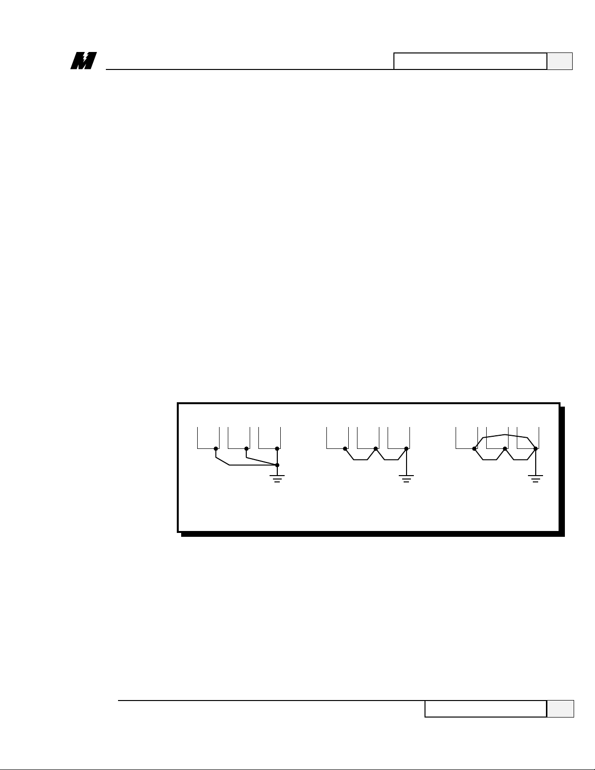
❏ Where several units are used side by side, all units should be grounded
directly to the ground pole. However, it is permissible to connect all the
ground terminals in series and ground only one unit to the ground pole (refer
to Figure 7). DO NOT FORM A LOOP WITH THE GROUND WIRES.
2
Installation and Start-Up
19
Electrical Hook-Up
3/21/96
❏ If dynamic braking resistors (DBR) are to be used, connect across motor
armature in series with loop contactor N.C. contact. (See Figure 5.)
Figure 7. Grounding of Multiple Units
CORRECT CORRECT NOT
ACCEPTABLE
GROUND
POLE
GROUND
POLE
GROUND
POLE
LA-10
Page 24

2
Installation and Start-Up
20
Using of An Analog Tachometer
3/21/96
❏ Inspect all equipment for signs of damage, loose connections, or other
related problem areas.
❏ Ensure the three phase line voltage is within +10% of the nominal input
voltage range of 230/460 VAC. Also verify that frequency is correct for the
drive system. Note that the drive is not sensitive to phase sequence. Input
power specifications are contained on the drive nameplate or the drive
system Schematic Diagram.
❏ Remove all shipping devices and relay wedges. Manually operate all
contactors and relays to ensure that they move freely .
Pre-Power
Check
CAUTION
To prevent damage to the drive, the following checks must be
performed before applying the input power.
IMPORTANT
In order to produce output to a motor, the power cube may also
need input and output signal connections for Local I/O. See
Schematic and/or Interconnection Diagrams for specific
connections.
The DSD 406 / 412 has provisions for an analog tachometer input at TB1
terminals 22 and 23. Either a DC or AC tachometer may be used as selected in
the PAC program. The hardware circuitry is designed for 75-120 volts DC or
50-85 volts AC of nominal input at rated top speed. For best performance, it is
recommended that a 50 volts per 1,000 rpm DC tachometer be used with 1750 or
2300 rpm motors.
If higher tachometer voltages are required, add an external resistor in series with
the tachometer wiring signal at terminal 23. Use 107 Kohms (±1%, 1/2 watt) for
each additional 100 volts expected signal. [ For example, add a 107 Kohm, 1%,
1/2 watt resistor in series with the tachometer wire at terminal 23 if a 100 volts
per 1,000 rpm DC tach is used with 1750 or 2300 rpm motors. ]
Use of An
Analog
Tachometer
CAUTION
The analog tachometer input channel may saturate if input
voltages exceed 150 volts DC or 106 volts AC at terminal 23.
This may cause loss of drive control and a drive speed runaway or component damage.
Page 25

2
Installation and Start-Up
21
Drive Start-Up
3/21/96
Drive Start-Up
❏ Ensure that all electrical connections are secure.
❏ Ensure that all transformers are connected for proper voltage according to
the drive system Schematic Diagram.
❏ Attach a DVM across the 115 VAC control power , at transformer T1
secondary terminals X1 and X2.
❏ Apply the three phase power and verify that the control power is between
103 VAC and 126 VAC as read on the DVM. Then press the RESET push
button on the front of the power cube, and observe the “Drive power-up
sequence” as described below .
NOTE: The "Drive Power-Up Sequence" is also described in the Operation
section of this manual under “Start-Up Operation”. If using upload/download
capabilities, please refer to DSD 406/412 Upload/Download procedure in the
Operation section.
❏ The “Drive Power-Up Sequence” can be observed by monitoring the
Standard Control/Display Unit (SCDU) on the front of the power cube.
❶ First, all of the segments on the digital LED display and all of the LEDs
will light for about one second.
❷ Then the LEDs and display extinguish and the drive will perform
internal checks.
❸ If the drive passes the self-test, then the READY LED will light and the
SCDU will display 'P-UP' to indicate a proper power-up.
Displays other than those mentioned above may occur. If abnormal display
conditions occur, the following actions maybe necessary to correct the situation:
● If no digits or LEDs ever light up, check for proper voltage between the 115
VAC control power lines, or for blown 115 VAC control power fuses, or for
a defective control voltage power supply in the power cube.
● If horizontal segment(s) of the SCDU display are lit, then one or more
phases of the three phase power are missing. Check the three phase power
fuses. See Section 3, Start-Up Operation, for more detailed information
about this test.
Page 26

2
Installation and Start-Up
22
Drive Start-Up
3/21/96
Parameter
Verification
● If the FAULT LED lights and a fault code appears on the SCDU, then refer
to the Fault/Error Codes List in Section 4, Maintenance, to see what caused
the fault and to find the correct solution. A fault code is the letter 'F'
followed by a number representing the fault. See Section 3, Operation, for
more detailed information about fault reporting and clearing.
● If the SCDU displays 'Prot', then the initial checks found that the protected
non-volatile RAM (NVRAM) has not been initialized. Move the NVRAM
PROTECTION switch to "OFF" in order to allow the CPU to initialize the
NVRAM with preprogrammed default values. Notice that the NVRAM
UNPROTECTED LED is now lit to indicate the NVRAM
PROTECTION switch position. Next, press the RESET push button. The
drive will go through its power up sequence again; however, this time it will
initialize the protected NVRAM. After the power up sequence has finished,
return the NVRAM PROTECTION switch to "ON" in order to assure
protection of this memory area. Notice that the NVRAM UNPROTECTED
LED is now turned off.
❏ On drives with fans, verify that the fans are working.
When the READY LED on the SCDU is lit, all the selectable parameter data
should be verified for the proper values as follows. See the PCDU Guide for
information on verifying and entering parameter values on a PCDU:
❏ VERIFY OR CHANGE EACH PARAMETER VALUE for the particular
application and motor involved.
❏ PCU DIAGNOSTICS (function # 998) should now be performed to verify
armature and field circuitry .
❏ SELF-TUNE (PCU Parameter Measurement) (function # 997) should be
performed before the drive is “RUN”. This gives the drive various motor
parameters essential for optimal operation. NVRAM protection must be off
to store parameters.
❏ SELF-TUNE SELECT (Function # *) should be turned on for optimal
operation. (* Check the PAC diagram for correct function number.)
❏ STORE PARAMETERS, (function # 994) so that power can be removed and
reapplied without losing the entered parameters. Remember that NVRAM
protection must be OFF to store parameters.
❏ Operate drive, using external control signal inputs shown on the system
schematic.
Page 27

3
Operation
23
3/21/96
Controls and Indicators
Controls and
Indicators
Pressing the reset button causes the drive to clear faults, or in some cases to reset
the drive, depending on the context.
To the right of the RESET button is a vertical strip of six light emitting diodes
(LEDs):
All status LEDs are under the control of the application specific software.
However, the following descriptions indicate typical uses for the LEDs. The
PAC diagram for this drive must be consulted to determine the actual meaning
for each LED.
Indicates that the drive is ready to operate.
DC loop contactor is closed and drive is controlling motor speed.
Drive is demanding armature current at or above the preset current limits.
RESET Button
Status LEDs
Ready
Run
Torque Limit
Figure 8. Operator Controls and Indicators
The “Operation” Section describes and illustrates the following:
● Operator’s controls and indicators.
● Steps you need to follow to start-up your DSD drive.
● Types of parameters that can be entered after start-up.
● Types of monitor functions available after start-up.
● Upload/Download of Programs or Parameters procedure.
● How to access error and fault lists and clear them.
● How to access non-volatile “RAM”.
● How to reload the default functions.
● Self-tuning feature.
The upper right corner of the power cube cover contains the operator controls
and indicators of the SCDU. Figure 8 identifies these operator components.
Although accessible with the cover in place, all of these components are part of
the DSD Drive Control PCB.
RESET
BUTTON
RUN (green)
READY (green)
SCDU
MEM
UNPROT
DOWN
NV RAM
PROTECTION
ENTER
E-STOP
(red)
FAULT (red)
OVERLOAD
(yellow)
TORQUE
LIMIT
(yellow)
+
DATA/FCTN
UP
LA-3
DATA
LED
DATA
PENDING
Page 28

3
Operation
24
Controls and Indicators
3/21/96
Standard
Control/Display
Unit (SCDU)
Non-Volatile
“RAM” Protection
Current exceeded safe levels for too long and drive was stopped to protect the
motor.
Drive contactor safety interlock is detected as open. Drive will not run when this
light is on.
Indicates that a declared drive fault exists. The Fault/Error Code List defines
what conditions the drive will recognize as faults.
IMPORTANT
Clearing a Fault from the Fault List is NOT THE SAME as
resetting the fault. Some faults are transient in nature and require
no further action after clearing the fault from the Fault List.
Others require some additional positive action to allow the drive
to continue to run. See the Fault/Error Code List for further
details.
The major part of the SCDU is a 4-1/2 digit numeric LED display . Each of its
four full digits can display the values of 0 to 9 plus limited alphabetic characters.
The so-called half digit can display only the value “1” and a plus or minus sign.
Below the numeric LED, is a single indicator and four push buttons. The four
push buttons (DATA/FCTN, ⇑[UP], ⇓ [DOWN], and ENTER) are used to
operate the SCDU.
Next to the numeric displays of the SCDU is a red LED labeled MEM
UNPROT. This LED is lit when the “protected” portion of the non-volatile
random access memory (NVRAM) can be written to. Protection of the NVRAM
is determined by the switch labeled NVRAM PROTECTION. When this
switch is in the "ON" position, the MEM UNPROT LED is off and the
protected portion of the NVRAM can not be written to. This prevents setup
parameters and other important constants from being accidentally erased or
changed. When these parameters need to be changed the switch can be moved
to the "OFF" position, removing the write protection and causing the MEM
UNPROT LED to be lit.
Fault
CAUTION
The NVRAM PROTECTION switch should be left in the
"ON" position to protect the NVRAM during the critical
power-up and power-down periods.
Overload
E-Stop
The optional Portable Control/Display Unit (PCDU) plugs into a telephone-style
jack at the bottom left of the DSD Drive Control PCB (accessible through a
cutout at the bottom left of the front cover). If your unit is equipped with this
option, refer to the PCDU guide provided with the unit for operating procedures.
Portable
Control/Display
Unit Connection
Page 29

3
Operation
25
Start-Up Operation
3/21/96
Start-Up
Operation
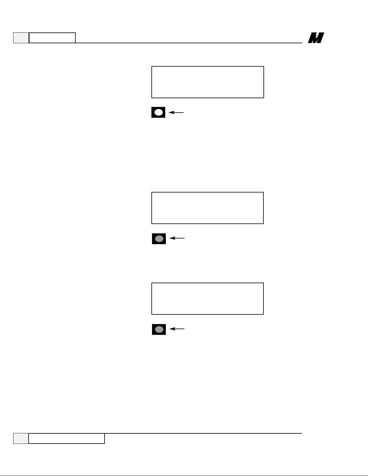
❏ When power is first applied to the drive, all of the segments on the 4-1/2
digit display will turn on briefly in order to show that all are functioning:
❏ After this lamp test is completed, an internal check is made to determine if
the NVRAM chips have ever been used before, or if the EPROMs are the
same as before power-down. If not, the drive software will attempt to load
the defaults into the NVRAM chips. The SCDU displays the word ‘Prot’ if
the NVRAM PROTECTION switch is in the “ON” position; this prevents
NVRAM updates:
If the display shows ‘Prot’, it is necessary to move the NVRAM
PROTECTION switch to the "OFF" position and press the RESET button
in order to load defaults into NVRAM and restart the drive. Then set the
NVRAM PROTECTION switch back to "ON". This message will only
happen when the drive is powered up for the very first time or if the software
in the drive or the NVRAM chips are changed.
❏ After the LED lamp test has completed, the drive software will now perform
a fuse test on each of the three line fuses. If any power conversion fuse is
open, the SCDU will indicate this on its display as follows:
1.8.8.8.8.
-
.
.
prot
-
DATA
RED
Page 30
3
Operation
26
General Operation
3/21/96
If two fuses are blown, the SCDU display will be:
The drive will not operate unless all three line fuses are functional. If the SCDU
indicates a bad fuse, power must be removed from the drive, the fuse replaced
and power reapplied.
❏ After the drive has performed all three tests (lamp test, “RAM” test, and fuse
test), the SCDU displays one of two final messages. If there are any faults
present at this time, the SCDU will display a Fault code. The display will be
similar to:
where the leading ‘F’ indicates a fault and the 3 digits following the ‘F’
indicate the fault number. If however, there are no faults present, the SCDU
displays the normal power-up message:
General
Operation
This ‘P-UP’ display will remain on the SCDU until a key is pressed or a fault
occurs.
After the drive has powered up and the SCDU display is showing ‘P-UP’ or a
fault number, it can be used to enter new parameters, monitor drive operation,
and/or perform certain drive diagnostics. Every operation that the SCDU can
perform is called a ‘function’. There may be up to 1000 functions defined.
The function codes between # 000 and # 999 are grouped as follows:
- -
DATA
RED
OFF
DATA
f 102
OFF
DATA
p-up
Page 31

3
Operation
27
General Operation
3/21/96
All SCDU functions have at least 2 levels and some functions use 3 levels. The
data indicator below the lower left corner of the 4-1/2 digit display is used to
indicate which level of a particular function the SCDU is currently at. The top
level of the SCDU operation is called the "Function" level. The data indicator is
off when the SCDU is in the "Function" level. The ⇑or ⇓ keys are used to select
a function number to be accessed while at this level. The ⇑ key increments the
function number in the display while the ⇓ key decrements it. The SCDU will
ramp the displayed function number when the ⇑ or ⇓ key is pressed and held for
1/2 second or longer.
The DATA/FCTN key is used to toggle between the “Data” level and the
“Function” level. Press the DATA/FCTN key when the desired function
number is in the display . At this point, the SCDU leaves the "Function" level
and enters the "Data" level. Note that the data indicator is now GREEN. This
operation is consistent for every function on the SCDU, although the data
actually displayed while the indicator is GREEN is function-number specific.
Examples of every type of SCDU function are given in subsequent sections. All
function numbers are the same for both the SCDU and the PCDU (Portable
Control/Display Unit). (See the “PCDU Guide” for steps required for PCDU
function entry .) There are some functions, however, that can only be performed
with the PCDU. When such a function number is selected on the SCDU and the
DATA/FCTN key is pressed, the SCDU’s display will change to:
Function # Description
# 000 Reserved for the Fault Display/Clear Function
# 001 - 299 PAC dependent Parameter Mode (Settable Parameters)
# 600 - 799 PAC dependent Monitor Mode (View Only Values)
# 800 - 899 Reserved for Advanced Fault/Error Routines
# 900 - 999 Reserved for Diagnostic/Test Routines
Table 2. # Function Code Descriptions
Function
Levels
DATA/FCTN
Key
OFF
DATA
pcdv
Page 32

❏ Press the DA TA/FCTN key to enter the "Data" level for this function
number. The data indicator is GREEN to verify that the number being
shown is the current actual value for this parameter. For example, if function
# 040 is currently set for a value of 10.6, it will be displayed as follows:
❏ Use the ⇑ and ⇓ keys to ramp the number in the SCDU display to the desired
value. Note that the data indicator is RED to verify that the value being
displayed is NOT the actual value, but rather is in the process of being
changed. Each parameter has an upper and lower limit depending on the
PAC diagram. The following display will occur when the lower limit is
exceeded:
❶ Similarly, if the upper limit is exceeded, the SCDU displays:
GREEN
DATA
10.6
3
Operation
28
3/21/96
Parameter Functions
Parameter
Functions
SCDU functions # 001 through # 299 inclusive are used to modify and/or
display setup points that the drive needs for operation. Items that would
typically fall into this category are functions such as Accel Times, Regulator
Gains, Rated Speed and any other parameter that has been previously
programmed in the PAC diagram for the drive. The following steps show how
to modify a given parameter via the SCDU display .
❏ Use the ⇑ and ⇓ keys to select the function number (between # 001 and
# 299) to be accessed. The data indicator is turned off during this step.
In the example below , function # 040 is chosen:
OFF
DATA
40
DATA
RED
----
Page 33

3
Operation
29
3/21/96
Parameter Functions
❷ The SCDU display will increment from ‘10.6’ to ‘11.0’ if the ⇑
key is pressed 4 times:
❏ Press the ENTER key to transfer the value in the SCDU display to the actual
value used by the drive. Note that the data indicator will change back to
GREEN to indicate that this value is now the actual value for this parameter:
If the ENTER key is pressed while the display is indicating that the upper or
lower limit has been exceeded, the display will change to the appropriate
limit value and the LED will change to GREEN.
The DATA/FCTN key can be pressed any time before the ENTER key is
pressed, to cancel the changes and return to the initial value.
❏ Press the DA TA/FCTN key to put the SCDU back into the "Function" level.
As with the example above, the SCDU display will be:
DATA
RED
----
11.0
DATA
RED
GREEN
DATA
11.0
OFF
DATA
40
All changes made become active values upon pressing the ENTER key.
They remain active until the next reset, or until the drive is powered down.
Page 34

3
Operation
30
3/21/96
Monitor
Functions
Monitor Functions
Due to PAC programming considerations it may be possible to access a
value which cannot be changed. In this case the CDU function will proceed
as described until the ENTER key is pressed to change the value. In this
case the value will simply ignore any requested changes and remain the
same.
SCDU functions # 600 through # 799 inclusive are used to monitor those values
that cannot be directly changed by the operator. Items that would typically fall
into this category are Speed Feedback, Armature Current and Armature Voltage.
To view one of these values, it must have been previously programmed in the
PAC Diagram for the drive. The following steps show how to display a given
value on the SCDU display .
❏ Use the ⇑ and ⇓ keys to select the function number (between # 600 and
# 799) to be accessed. The data indicator is turned off during this step. For
example, if function # 604 is selected, the SCDU display will be:
❏ Press the DA TA/FCTN key to enter the "Data" level for this function
number. The data indicator is GREEN to indicate that actual data is
currently being viewed. If the data for function # 604 is currently at 20.94
for example, the SCDU display will change to:
OFF
DATA
604
When the drive is reset or powered up the value reverts to the value stored in
NVRAM. If changes are to be permanent, use function # 994 (described
later) to save the changed value in NVRAM.
GREEN
DATA
20.94
The SCDU’s display is updated immediately if the value for the selected
function changes.
NOTE: Values displayed with these function numbers cannot be modified.
Page 35

3
Operation
31
3/21/96
Upload/Download of Program/Parameters
Upload/
Download of
Programs or
Parameters
(T992)
In addition to the electrical connections, a serial communications
program must be used by the computer to access data through the
serial port. The serial port communications program must support Y
Modem Batch file transfer protocol (i.e. Qmodem).
Figure 9: DSD 406/412 to IBM PC Compatible
Computer Interconnect Diagram
The “Upload/Download of Programs or Parameters” Section describes
and illustrates the following:
● What is upload/download.
● General upload/download procedures.
● How to upload program into a new Flash ROM chip.
● How to upload a program.
● How to download a program.
● How to upload parameters.
● How to download parameters.
The DSD 406/412 have the ability to pass program and parameter
information between the drive’s memory and a computer with a serial
port. The direction of data flow is defined as Upload (from the
computer to the drive) or Download (from the drive to the computer).
Figure 9 shows the electrical connections required to connect the serial
port of the DSD 406/412 to the serial port (COM1 or COM2) of an IBM
PC compatible computer. The PC utilized must have a serial port and
disk drive.
ISOLATED
RS232 PORT
DB25 TO RJ12
CONVERTER
(P/N 46S03027-0010)
RJ12 CABLE
(P/N 05P00211-004)
9 TO 25 PIN
CONVERTER
(P/N 50210702)
IBM PC
COMPATIBLE
COM 1
Upload/
Download
Introduction
and Definitions
Page 36

3
Operation
32
3/21/96
The default data bit, stop bit and parity values of the drive are “8”, “1”
and “NO”, respectively. These settings can not be changed. The Y
Modem Batch file transfer is the only protocol available for
communicating with the DSD 406/412.
In uploading and downloading
files, the drive behaves like a
bulletin board service to the PC.
A file upload means that a file
is sent from the PC to the drive.
A file download means that a
file is sent from the drive to the
PC.
There are two file types associated with upload and download. The
PAC program file (i.e. the .PRG file) contains the executable
instructions that determine the application characteristics of the drive.
The parameter file is the file of all the parameter settings of a drive at
the time the .PAR file was captured.
● Program upload is the process of a computer sending a new
PAC program (i.e. the .PRG file) to a DSD 406/412 through the
drive’s serial port. This process may be required when, upon
application of power, the drive finds the PAC program loaded
into memory is invalid. This process may also be used when it is
desired to change the PAC program from what was previously
loaded. Some of the steps shown below are skipped when the
PAC program in memory is found to be invalid.
● Program download is the process of the DSD 406/412 drive
sending the PAC program (i.e. the .PRG file) through the drive’s
serial port to a computer. This process can be used for memory
backup.
● Parameter upload is the process of a computer sending all
settable parameters (i.e. the .PAR file) to a DSD 406/412 drive.
This process can be used to set up the drive with a set of tuned
constants.
Upload/Download of Program/Parameters
CAUTION
The communications software must be set up to match
the baud rate of the drive.
Communications Program Set-up
protocol: Y Modem Batch
parity: NO
data: 8
stop: 1
speed: 9600 or 19200
Page 37

3
Operation
33
3/21/96
General
Upload/
Download
Procedures
● Parameter download is the process of the DSD 406/412 drive
sending all of its settable parameter values (i.e. the .PAR file) to
a computer. This process can be used for memory backup. A
parameter download is the only data transfer process that can
occur while the drive is running a motor.
NOTE
The DSD 406 / 412 can not be running a motor while uploading
parameters or a program. It cannot also be running a motor if a
program download is occurring. The PAC program stops
execution during this time.
To perform an upload or download use function # 992. This will allow
you to upload or download PAC programs and parameters. The
following steps explaining how to perform these operations from the
Command/Display Unit, SCDU, resident on the drive:
❏ Check to verify the DATA PENDING light is “OFF”. If not,
press the DATA/FCTN key.
❏ Use the ⇑ and ⇓ keys to select function # 992. The display will
show the function number.
❏ Press the DATA/FCTN key. At this point the DATA/FCTN key,
the ⇑ key and the ⇓ key may be pressed.
● Press the DATA/FCTN key to return to the function entry
mode without performing any data transfers.
General Upload/Download Procedures
OFF
DATA
992
CAUTION
The NVRAM PROTECTION switch needs to be in the
“OFF” position to perform an upload.
The MEM UNPROT light will also need to be lit.
Page 38

3
Operation
34
3/21/96
● Press the ⇑ key to select an upload operation.
● Press the ⇓ key to select a download operation.
❏ Press the ENTER key to accept the Upload or Download
selection. At this point the DATA/FCTN key, the ⇑ key,
and the ⇓ key may be pressed.
● Press the DATA/FCTN key to return to the function entry
mode without performing any data transfers.
● Press the ⇑ key to select transfer of the program.
● Press the ⇓ key to select transfer of the parameters.
GREEN
DATA
pa(
GREEN
DATA
data
General Upload/Download Procedures
GREEN
DATA
send
GREEN
DATA
recv
❏ Press ENTER to accept the given action.
Page 39

3
Operation
35
3/21/96
The DSD 406/412 will automatically go into the upload/download
function # 992, on power up of a drive without DCU software or
replacement of a Flash ROM chip. The default baud rate of 19,200 will
be displayed.
❏ Use the ⇓ key to select the another baud rate if your terminal
does not support 19,200 baud. This will decrease the baud rate.
The ⇑ key is not applicable here since 19,200 is the maximum
baud rate.
❏ Press the ENTER key to accept the displayed baud rate. The
DSD 406/412 will begin to initiate transfer sequence.
A message will appear explaining that permanent storage memory is
being erased.
CAUTION
The communications software must be set up to match
the baud rate of the drive.
CAUTION
When the program transfer begins it must be completed.
eras
General Upload/Download Procedures
Upload
Procedure for a
New Flash ROM
Chip
WARNING
After putting in a new Flash ROM chip and
19,200 baud is not displayed on the SCDU,
contact MagneTek for assistance.
19200
Page 40

3
Operation
36
3/21/96
A message will appear explaining that the DSD 406/412 is attempting
to start the program transfer.
At this time, the DSD 406/412 is waiting to communicate with the PC.
You will see the LED’s on drive scroll upward to indicate it is ready to
upload. Y Modem protocol will be sent to the serial port in the form of
a ‘C’ character indicating that the transfer can start.
Initiate a Y Modem Batch file transfer from the PC (i.e. for Q modem
users, press the PgUp key for an upload and select the Y Modem batch
mode).
When transfer begins, a message will appear showing how much of the
transfer has already taken place. For a baud rate of 19,200, the transfer
will take approximately five minutes. The completion percentage
number counts as more data is transferred.
The LED’s will continue to scroll upward until the upload is complete.
When the upload finishes, the drive resets itself, runs an internal check,
and then executes the PAC program.
General Upload/Download Procedures
l0ad
GREEN
DATA
78
Page 41

3
Operation
37
3/21/96
❏ Press the DATA/FCTN key.
❏ Press the ⇑ key to select an upload operation.
❏ Press the ENTER key to accept the Upload selection.
❏ Press the ⇑ key to select transfer of the program.
❏ Use the DATA/FCTN key to exit out of the program upload
without performing any data transfers.
General Upload/Download Procedures
❏ Check to verify that the DATA PENDING light is “OFF”. If not,
press the DATA/FCTN key.
❏ Use the ⇑ and ⇓ keys to select function # 992. The display will
show the function number.
Program Upload
CAUTION
When the program transfer begins, it must be completed
because the existing program is erased.
OFF
DATA
992
GREEN
DATA
re(v
GREEN
DATA
pa(
Page 42
3
Operation
38
3/21/96
❏ Use the ⇓ key to select the another baud rate.
❏ Press the ENTER key to accept the displayed baud rate. The
DSD 406/412 will begin to initiate transfer sequence.
A message will appear explaining that permanent storage memory is
being erased.
A message will appear explaining that the DSD 406/412 is attempting
to start the program transfer.
General Upload/Download Procedures
❏ Press the ENTER key to accept the transfer of the program.
The current baud rate will be displayed.
19200
eras
l0ad
At this time, the DSD 406/412 is waiting to communicate with the PC.
You will see the LED’s on drive scroll upward to indicate it is ready to
upload. Y Modem protocol will be sent to the serial port in the form of
a ‘C’ character indicating that the transfer can start.
Initiate a Y Modem Batch file transfer from the PC (i.e. for Qmodem
users, press the PgUp key for an upload and select the Y Modem batch
mode).
CAUTION
The communications software must be set up to match
the baud rate of the drive.
Page 43

3
Operation
39
3/21/96
When transfer begins, a message will appear showing how much of the
transfer has already taken place. For a baud rate of 19,200, the transfer
will take approximately five minutes. The completion percentage
number counts as more data is transferred.
The LEDs will continue to scroll upward until the transfer is complete.
When the upload finishes, the drive resets itself, runs an internal check,
and then executes the PAC program.
❏ Check to verify that the DATA PENDING light is “OFF”. Press
the DATA/FCTN key.
❏ Use the ⇑ and ⇓ keys to select function # 992. The display will
show the function number.
❏ Press the DATA/FCTN key.
❏ Press the ENTER key to accept the Download selection.
General Upload/Download Procedures
Program
Download
GREEN
DATA
78
GREEN
DATA
send
OFF
DATA
992
Page 44
3
Operation
40
3/21/96
❏ Press the ⇑ key to select transfer of the program.
❏ Use the DATA/FCTN key to exit out of the program download
without performing any data transfers.
❏ Press the ENTER key to accept the transfer of the program.
The current baud rate will be displayed.
❏ Use the ⇓ key to select the another baud rate if your terminal
does not support 9,600 baud. The maximum baud rate for a
download is 9,600.
❏ Press the ENTER key to accept the displayed baud rate. The
DSD 406/412 will begin to initiate transfer sequence.
Initiate a Y Modem Batch file transfer from the PC (i.e. for Qmodem
users, press the PgDn key for a download and select the Y Modem
batch mode).
General Upload/Download Procedures
GREEN
DATA
pa(
CAUTION
File can not already exist in directory you are trying
to download to.
CAUTION
The maximum baud rate is different from a program
download.
9600
Page 45

3
Operation
41
3/21/96
❏ Check to verify the DATA PENDING light is “OFF”. If not,
press the DATA/FCTN key.
❏ Use the ⇑ and ⇓ keys to select function # 992. The display will
show the function number.
❏ Press the DATA/FCTN key.
❏ Press the ⇑ key to select an upload operation.
General Upload/Download Procedures
NOTE
The downloaded program is already named in the PAC program.
At this time, the DSD 406/412 is waiting to communicate with the PC.
When the transfer begins, a message will appear showing how much of
the transfer has taken place. The completion percentage number
counts as more data is transferred. This transfer should take ten
minutes at 9,600 baud.
GREEN
DATA
re(v
OFF
DATA
992
GREEN
DATA
78
Parameter
Upload
Page 46

3
Operation
42
3/21/96
❏ Use the DATA/FCTN key to exit out of the parameter upload
without performing any data transfers.
❏ Press ENTER to accept the transfer of the parameters.
The current baud rate will be displayed.
❏ Use the ⇓ key to select the another baud rate if your terminal
does not support 9,600 baud. The maximum baud rate for a
download is 9,600.
❏ Press the ENTER key to accept the displayed baud rate. The
DSD 406/412 will begin to initiate transfer sequence.
Initiate a Y Modem Batch file transfer from the PC (i.e. for Qmodem
users, press the PgUp key for an upload and select the Y Modem batch
mode).
At this time, the DSD 406/412 is waiting to communicate with the PC.
When the transfer begins, a message will appear showing how much of
General Upload/Download Procedures
9600
CAUTION
The communications software must be set up to match
the baud rate of the drive.
❏ Press the ENTER key to accept the Upload selection.
GREEN
DATA
data
CAUTION
The maximum baud rate is different from a program
download.
Page 47

3
Operation
43
General Upload/Download Procedures
3/21/96
the transfer has already taken place. For a baud rate of 9,600, the
transfer will take approximately thirty seconds. The completion
percentage number counts as more data is transferred.
❏ Check to verify the DATA PENDING light is “OFF”. If not,
press the DATA/FCTN key
❏ Use the ⇑ and ⇓ keys to select function # 992. The display will
show the function number.
❏ Press the DATA/FCTN key.
❏ Press the ENTER key to accept the Download selection.
Parameter
Download
GREEN
DATA
78
OFF
DATA
992
GREEN
DATA
send
GREEN
DATA
data
Page 48

3
Operation
44
General Upload/Download Procedures
3/21/96
❏ Use the DATA/FCTN key to exit out of the parameter download
without performing any data transfers.
❏ Press ENTER to accept the transfer of the parameters.
The current baud rate
will be displayed.
❏ Use the ⇓ key to select the another baud rate if your terminal
does not support 9,600 baud. The maximum baud rate for a
download is 9,600.
❏ Press the ENTER key to accept the displayed baud rate. The
DSD 406/412 will begin to initiate transfer sequence.
Initiate a Y Modem Batch file transfer from the PC (i.e. for Qmodem
users, press the PgDn key for a download and select the Y Modem
batch mode). The PAC program will assign a name to the downloaded
file.
At this time, the DSD 406/412 is waiting to communicate with the PC.
When the transfer begins, a message will appear showing how much of
the transfer has already taken place. The completion percentage
number counts as more
data is transferred. This
transfer should take
approximately thirty
seconds at 9,600 baud.
GREEN
DATA
78
CAUTION
The communications software must be set up to match
the baud rate of the drive.
9600
CAUTION
The maximum baud rate is different from a program
download.
Page 49

3
Operation
45
3/21/96
Error Handling/Reporting
Error Handling/
Reporting
The drive has two methods available to report errors. Each error condition may
utilize ONE OR BOTH OR NEITHER of the reporting methods.
The most conventional method is called ‘fault recording’. If this method is
enabled for a particular error, the red FAULT LED and a unique fault code
number will appear on the SCDU at the moment the error occurs. Each
occurrence of a fault is recorded in an area in “RAM” called the Fault List. The
Fault List stores the first 16 faults to occur after the drive is powered up,
meaning it will contain the 16 “oldest” faults. Recording of faults stops as soon
as the 16th fault occurs. This list is erased when the drive is powered down or
reset. Whether the drive stops or continues to run is dependent on the way the
particular fault is implemented within the PAC diagram. Most standard faults
are set up so that the drive will stop if a fault occurs.
The second method for error handling is called ‘error recording’. Error
recording differs from fault recording in three respects:
❶ The error condition will not be shown on the SCDU or the red FAULT LED.
❷ The error list stores the last errors to occur, meaning it will contain the 16
most recent errors. Each new error over-writes the oldest error in the list.
❸ This list is maintained in battery-backed-up “RAM” and is retained when the
drive is powered down or reset.
Again, the action taken by the drive when an error occurs depends on how the
particular error is implemented within the PAC Diagram.
Function # 801 is used to display or alter the Error Disposition List. This list can
be consulted at any time to determine whether a particular condition should be
reported as an error, a fault, or both. The process for changing the entry in the
disposition list for a particular condition using the SCDU is as follows:
❏ Use the ⇑ and ⇓ keys to select function # 801 from the function level. The
data indicator is off during this step.
OFF
DATA
801
Page 50

3
Operation
46
3/21/96
e.if.0
DATA
RED
Error Handling/Reporting
❏ Press the DA TA/FCTN key to enter the "Data" level for function # 801.
The data indicator is GREEN and the error code last modified with function
# 801 will be in the SCDU display . The SCDU displays error code # 13
(illegal instruction) initially after power up:
❏ Use the ⇑ and ⇓ keys to select the error code entry in the Disposition List
that is about to changed/viewed. For example, if the disposition for error
code # 102 (Numeric Underflow) is to be modified, press the ⇑ key until the
SCDU display changes to:
GREEN
DATA
102
❏ Press the ENTER key when the desired error code is displayed on the
SCDU. The data indicator changes from GREEN to RED, and the SCDU
display changes as well to a format of ‘E.xF.y’. The ‘E’ and ‘F’ are
abbreviations for Error and Fault respectively . The ‘x’ and ‘y’ will be either
‘1’ or ‘0’ to indicate which list will record the error. For example, if the
display is ‘E.1F.1’, the error is recorded in both lists. If the display is
‘E.0F.1’, the error is recorded in the fault list, but not in the error list. If the
display is ‘E.0F.0’, neither list records the error. In the example above, the
factory set default disposition for a Numeric Underflow (code # 102) is to
record the error in the Error List, but not in the Fault List. In this case, the
SCDU display is:
GREEN
DATA
13
Page 51

3
Operation
47
3/21/96
Error Handling/Reporting
❏ Press either the ⇑ or ⇓ keys repeatedly to change the numbers after the ‘E’
and ‘F’ from ‘1’ to ‘0’ and vice-versa. Starting from no declarations, the
displays are: ‘E.0F.0’, ‘E.0F .1’, ‘E.1F.0’, and ‘E.1F.1’. For example, if the
disposition for this error should be changed so that it is NOT recorded in
either the Fault or Error list.
❶ Press the ⇓key once so the display changes to:
e.0f.1
DATA
RED
This display indicates that the Numeric Underflow error will now be
recorded in the Fault List, but not in the Error List.
❷ Pressing the ⇓key once more will change the display to:
e.0f.0
DATA
RED
This is the desired status for the new disposition of the Numeric Underflow
error, which is to not report it to either the Fault or Error List.
❏ Press the ENTER key when the new disposition code is in the display. At
this point, the data indicator changes from RED to GREEN, and the SCDU
displays the error code again:
GREEN
DATA
102
Page 52

3
Operation
48
3/21/96
Fault
Display/Clear
GREEN
DATA
t0p
Error Handling/Reporting
❏ The ⇑ and ⇓ keys will now be used to select which error code is being
modified.
When all changes in the Error Disposition List are finished, the
DATA/FCTN key will exit back to the function level:
OFF
DATA
801
The drive stores the first 16 faults that have been reported to the Fault List.
Once the Fault List is filled with 16 faults, it will not accept any more entries.
The data in this buffer is not retained when the power is lost. Each time a fault
condition occurs, and its entry in the Disposition List is set to allow recording in
the Fault List, that new fault is placed on the list.
Function # 000 is reserved for viewing the Fault List. Each fault in the Fault List
can be shown on the SCDU display and optionally cleared. The steps to view the
Fault List are as follows:
❏ Use the ⇑ and ⇓ keys to select function # 000. The data indicator is off
during this step. Note that this function can be accessed simply by pressing
the ⇑ key once if the SCDU display is ‘P-UP’.
❏ Press the DA TA/FCTN key to enter the "Data" level for this function. The
data indicator is GREEN to indicate that the fault codes currently in the Fault
List are being displayed. The very first display at this point is the word
'TOP':
OFF
DATA
0
Page 53

3
Operation
49
3/21/96
Error Handling/Reporting
❏ T o view the first fault on the list, press the ⇓key. If there is a Numeric
Underflow fault on the Fault List, for example, the SCDU display will
change to:
GREEN
DATA
102
❏ The contents of the Fault List may be examined by using the ⇑ and ⇓ keys.
The first fault in the list is the first fault actually declared. When the first
fault in the list is displayed, pressing the ⇓ key will cause the next fault to be
displayed. Repeatedly pressing this key will move toward the end of the list.
The SCDU displays the word 'End' after the last fault has been displayed:
GREEN
DATA
end
Error Display
❏ When any fault other than the first fault is displayed, pressing the ⇓ key will
cause the previous fault to be displayed.
For example, if the 10th fault in the list was displayed, the end of the list
(“End”) could be reached by repeatedly pressing the ⇓ key, and the
beginning of the list (“top”) could be reached by repeatedly pressing the ⇑
key .
The drive is able to store the most recent 16 errors that have been reported to the
Error List. This list is constantly updated, with the newest error overwriting the
oldest in the list. This list is held in battery-backed-up “RAM” (NVRAM), so it
is retained when power is lost. Each time an error condition occurs, and if its
entry in the Disposition List is set to allow recording in the Error List, that new
error is placed in the list. In addition to the error code, the Error List holds
number of the PAC block that declared the error, and a time-stamp to indicate
how much time has elapsed since the error occurred. This timer is only updated
while power is applied to the drive. The time-stamp can only be viewed by the
PCDU (see the PCDU Guide), but the PAC block number can be read by the
SCDU.
Page 54

3
Operation
50
3/21/96
❷ The number of the PAC block that declared this error can be viewed by
pressing the ENTER key. If block 485 had declared the Numeric
Underflow error, for example, the SCDU would change to:
If the number displayed during this step is 0, the error was not declared by a
PAC block, but rather by the Kernel of the DCU.
Other errors currently in the Error List can be viewed by pressing the ENTER
key to display the Error Code again, then either the ⇑ or ⇓ key to move to the
next or previous slot in the list. The procedure outlined above should be
repeated as necessary to view the Error Code and PAC block number for other
errors in the Error List.
485
DATA
RED
Error Handling/Reporting
Function # 800 is reserved for viewing the Error List in NVRAM. The steps to
view the Error List are as follows:
❏ Use the ⇑ and ⇓ keys to select function # 800. The data indicator is off
during this step.
❏ Press the DA TA/FCTN key to enter the "Data" level for the view error
function.
❶ The data indicator is GREEN to indicate that an error code is currently
being viewed. If the error in this slot is a Numeric Underflow for
example, the SCDU will display:
OFF
DATA
800
GREEN
DATA
102
Page 55

3
Operation
51
3/21/96
Non-Volatile “RAM”-Access
Non-Volatile
“RAM”-Access
Every parameter that the drive uses has three separate areas in memory
associated with it. There is a factory-set default value for each parameter which
is stored in the read only EPROM chips. There is an area in the active “RAM”
which the drive uses while it is running. There is also an area in NVRAM
reserved for each parameter. The values in the NVRAM area are copied to the
active “RAM” every time the drive is powered up . This split level approach
makes it possible to return to the last set of ‘stable’ parameters in NVRAM if
some errors are made during fine-tuning of the active drive parameters.
Function # 994 is used to perform the transfer of data between the NVRAM and
active parameter lists. The process for copying data to or from the NVRAM
parameter list is as follows:
❏ Use the ⇑ and ⇓ keys to select function # 994 from the function level. The
dual-colored LED is off during this step.
❏ Press the DA TA/FCTN key to enter the "Data" level for function # 994.
The data indicator is GREEN to indicate that this function is currently being
accessed. It is possible to SAVE the current active parameters in “RAM” to
the NVRAM parameter list, or to RESTORE the current parameters from
the NVRAM parameter list to the active “RAM”. Note that a RESTORE is
the same operation that occurs inherently every time the drive is powered
up. Upon entering the data level for this function, the SCDU displays:
OFF
DATA
994
GREEN
DATA
rest
❏ The ⇑ and ⇓ keys can be used to toggle between the above display, which
indicates a pending RESTORE operation, and the following display, which
indicates a pending SAVE:
saue
DATA
RED
Page 56

3
Operation
52
3/21/96
IMPORTANT
During normal operation, and during drive power-up or -down,
the NVRAM PROTECTION switch should ALWAYS be in the
“OFF” position which prevents writes to the NVRAM.
saue
DATA
RED
Non-Volatile “RAM”-Access
Note that as soon as either the ⇑ or ⇓ key is pressed, the data indicator will
change to RED.
❏ Press the ENTER key to actually perform the transfer of data. If ENTER is
pressed while 'SAVE' is displayed, the SCDU display may change to:
This display means that the NVRAM PROTECTION switch is in the “ON”
position preventing writes to the NVRAM. Move the switch to the "OFF"
position, press the DATA/FCTN key, and start over from step #2. (See
Figure 3 in Section 3, Controls and Indicators for the location of the
NVRAM PROTECTION switch.)
During SAVE or RESTORE operation, the DATA/FCTN, ⇑ and ⇓, ENTER
keys will not function. Functionality will resume when operation is
complete.
prot
Page 57

3
Operation
53
3/21/96
Load Defaults Function
Load Defaults
Function
Every parameter in the drive has a factory-set default value that is loaded when
the drive is powered up for the very first time. These default parameters may not
be optimal values for the drive when actually running, but they will generally
allow the drive to function. It is possible to reload these default parameters with
function # 995 of the SCDU. A re-load of the defaults would generally be done
when the drive is operating erratically and it is suspected that one or more
parameters were improperly set and saved.
CAUTION
Use of the LOAD DEFAULTS function will overwrite EVERY
parameter currently being used by the drive with the factory-set
default for each parameter. There is no way to restore
parameters to their previous value once this function is used.
CAUTION
The NVRAM protection switch must be off and the drive must
be in the stop condition.
Function # 995 is used to perform the transfer of data from the default parameter
list to the ACTIVE “RAM” parameter list. The process for accessing the Load
Defaults Function is as follows:
❏ Use the ⇑ and ⇓ keys to select function # 995 from the function level. The
data indicator is off during this step.
OFF
DATA
995
❏ Press the DA TA/FCTN key to enter the "Data" level for function # 995. The
data indicator is GREEN to indicate that this function is currently being
accessed. The SCDU display may change to:
❏ Press the ENTER key to actually perform the Load Defaults transfer.
GREEN
DATA
l0ad
Page 58

3
Operation
54
3/21/96
WARNING
Armature current is circulated through the armature
circuit during parts of the PCU Parameter Measurement
function. The PCU will reduce the field current to zero on
motors with a shunt field in order to minimize motor
rotation. However, a PERMANENT MAGNET motor
must have its shaft locked mechanically prior to running
the PCU Parameter Measurement routine. If the PCU
detects significant motor voltage during the test, the PCU
parameter measurement function will abort.
Self-Tune (PCU Parameter Measurement)
Self-Tune (PCU
Parameter
Measurement)
If the drive is still in a run condition: To correct, put the drive in a stop
condition and press the DAT A/FCTN key to continue with loading defaults.
If the NVRAM protection switch is “ON”: To correct, turn off the NVRAM
protection switch and press the DAT A/FCTN key to continue with loading
defaults.
The DSD drive has a built-in current regulator SELF TUNING feature. When
activated, this feature measures total motor armature circuit resistance,
inductance including wiring, and the field L/R time constant. The drive then
uses the measured value in conjunction with the parameter entered for
“crossover frequency” to calculate integral and proportional gains for the current
regulator and to set the field regulator gains properly . After running the PCU
Parameter Measurement function, the values for armature resistance and
armature inductance are stored in NVRAM. Note that the NVRAM protection
must be turned “OFF” so that the results can be stored. It is possible to override
the values dynamically calculated for armature resistance and inductance values
by disabling the “USE SELF-TUNE” item in the parameter menu.
The dynamically calculated values are used if “USE SELF-TUNE” is set to
“ON” while the manually entered values are used if this item is set to “OFF”.
Prot
The drive will then do a complete reset and the program defaults are now
loaded.
If the SCDU display does not change to LOAd, the following may display .
St0p
Page 59

3
Operation
55
3/21/96
Self-Tune (PCU Parameter Measurement)
The process for accessing the PCU PARAMETER MEASUREMENT function
is as follows:
❏ Use the ⇑ and ⇓ keys to select function # 997 from the function level. The
data indicator is turned off during this step.
❏ Press the DA TA/FCTN key to enter the "Data" level for function # 997. The
data indicator will be GREEN to indicate that this function is currently being
accessed. The SCDU displays the word 'Prot' if the NVRAM
PROTECTION switch is in the position that will not allow any updates to
the NVRAM:
If the ‘Prot’ message appears, press the DAT A/FCTN key to return to the
"Function" level, move the NVRAM PROTECTION switch to the "OFF"
position, and press the DATA/FCTN key again. The SCDU will jump to the
‘Entr’ message (below) if the NVRAM PROTECTION switch is in the
correct position upon entering this function.
The SCDU displays the word ‘Entr’ to prompt the user to press the ENTER
key as further confirmation that the PCU parameter measurement function is
about to be performed:
OFF
DATA
997
prot
GREEN
DATA
entr
❏ Press the ENTER key to actually start the PCU Parameter Measurement
function. The PCU will not begin the measurement routine if a SEVERE
PCU FAULT exists. The PCU will declare a SEVERE FAULT under several
conditions including an IST fault, power supply failure, loss of line
synchronization, low line, or DCU failure. If a SEVERE FAULT exists
when the PCU starts the parameter measurements, the SCDU displays:
Page 60

3
Operation
56
3/21/96
Self-Tune (PCU Parameter Measurement)
❏ When testing is complete, press the DA TA/FCTN key to exit the PCU
parameter measurement routine and return to the "Function" level. The
SCDU displays:
❏ Severe faults can only be cleared by cycling power to the drive and replacing
the bad component if applicable. The SCDU displays the word ‘tESt’ while
it is performing the parameter measurements if there were no SEVERE
FAULTS when the ENTER key was pressed:
❏ Upon completion of the measurement, the SCDU will indicate the status of
the test. If an error occurred, the SCDU will display an appropriate fault
number. If all tests were completed properly, the SCDU displays ‘PASS’:
GREEN
DATA
sflt
GREEN
DATA
test
GREEN
DATA
pass
GREEN
DATA
997
Page 61

4
Maintenance
57
3/21/96
The “Maintenance” Section describes and illustrates the following procedures:
● Preventive Maintenance
● PCU Diagnostics
● Troubleshooting Guide
● Replacement Procedures for fuses, DSD Drive Control PCB, Armature
Interface PCB, fan, and power supply .
Preventive
Maintenance
Preventive maintenance is primarily a matter of routine inspection and cleaning.
The most important factors are that there is sufficient air flow to cool the drive
and that vibration has not loosened any connections.
The DSD drive is designed to have sufficient air flow for long, reliable
operation. Accumulated dust or dirt can reduce this air flow . Check and clean
all fans, filters (if any), and the air flow across the heat sinks for dust or dirt at
least once every three months. It may be necessary to do this more often if
conditions are harsh dirty filters should be replaced.
If the drive is subjected to vibration, all mounting and electrical connections
should be checked at three month intervals. Any loose hardware should be
tightened.
Preventive Maintenance
WARNING
Hazardous voltages may exist in the drive circuits even
with drive circuit breaker in off position. Never attempt
preventive maintenance unless incoming three-phase and
control power is disconnected and locked out.
Page 62

4
Maintenance
58
3/21/96
GREEN
DATA
entr
❏ Press the DA TA/FCTN key to enter the "Data" level for function # 998. The
DAT A Indicator is GREEN to indicate that this function is currently being
accessed. The SCDU prompts the user to press the ENTER key by
displaying:
OFF
DATA
998
The process for accessing the PCU diagnostics function is as follows:
❏ Use the ⇑ and ⇓ keys to select function # 998 from the function level. The
DAT A Indicator is off during this step.
Armature current is circulated through the armature
circuit during parts of the PCU diagnostics function. The
PCU will reduce the field current to zero on motors with a
shunt field in order to minimize motor rotation. However,
a permanent magnet motor must have its shaft locked
mechanically prior to running the PCU diagnostics routine.
If the PCU detects significant motor voltage during the test,
the PCU diagnostics function will abort.
WARNING
The drive has built-in diagnostic routines that can be performed via the SCDU.
The PCU diagnostic routines are able to test for four failure modes. The first test
checks the integrity of the three line fuses. Assuming the three line fuses are all
OK, the PCU then performs a test for shorted SCRs/doubler packs. If this test
indicates no shorted SCRs/doublers, the PCU then verifies that less than 5% of
the value entered for “Rated Field Current” is attainable. The PCU then tests for
open SCRs by passing current through the forward bridge followed by the
reverse bridge, and finally checks polarity of voltage feedback. The result of the
test is displayed on the SCDU after the test completes. The SCDU will light
certain unique LED patterns on its display corresponding with the failure (see
displays in the procedure that follows). The Fault Codes F910, F911, F912, and
F917 will not appear on the SCDU if the Error Disposition List is programmed
so that they are not reported to the Fault List (see “Error Handling/Reporting” in
the Operation Section).
Power
Conversion
Unit
Diagnostics
Power Conversion Unit Diagnostics
Page 63

4
Maintenance
59
Power Conversion Unit Diagnostics
3/21/96
❏ Press the ENTER key to actually start the PCU diagnostics. While the PCU
is performing the diagnostics test, the SCDU displays:
The PCU will not begin the diagnostic routines if a SEVERE PCU FAULT
exists. The PCU will declare a SEVERE FAULT under several conditions
including an IST fault, power supply failure, line sync loss, low line, or DCU
failure. If a SEVERE FAULT exists when the PCU starts the diagnostic tests,
the SCDU displays:
➊ Severe faults can only be cleared by pressing the RESET button on
the Main CPU Control PCB or by cycling power to the drive.
❷ If the display stays on 'tESt' and the contactor doesn't pick up, there is a
fault in the motor field connections.
❸ There are 4 dif ferent kinds of displays possible on the SCDU after the
PCU diagnostic routines complete. If all tests indicate that there are no
failed power components (SCRs and fuses), the SCDU displays:
GREEN
DATA
test
GREEN
DATA
sflt
GREEN
DATA
pass
Page 64

4
Maintenance
60
Power Conversion Unit Diagnostics
3/21/96
❏ Press the DA TA/FCTN key to exit the PCU diagnostic routine and return
to the "Function" level. The SCDU displays:
➊ If the PCU detects one or more open AC fuses, it displays the fault code
for a blown fuse ( F910 ):
❷ If the PCU detects one or more shorted SCR/doubler packs, the SCDU
displays the fault code for a shorted doubler ( F91 1):
❏ Remove power from the drive, consult the Maintenance Guide, or call
MagneTek for assistance, to replace the SCR(s) that are shorted, and perform
this test again.
If the PCU detected one or more open SCR/doubler packs, the SCDU
displays the fault code for an open SCR/doubler pack ( F912 ):
❏ Remove power from the drive, consult the Maintenance Guide, or call
MagneTek for assistance, to replace the SCR(s) that are open, and repeat this
test until the SCDU displays the 'PASS' massage.
OFF
DATA
998
OFF
DATA
f910
OFF
DATA
f911
OFF
DATA
f912
Page 65

Fault/Error Possible Causes &
Code
Fault/Error Name
Corrective Actions
120 VAC control power is not present.
➊ Check any circuit breakers or fuses in
this circuit. See “Replacing Fuse(s)”/
Maintenance Section.
❷ Check connection at J11. See
“Connectors on Drive Control PCB”/
Maintenance Section.
Each line indicates a blown fuse.
➊ Check for blown fuses. See “Replacing
Fuse(s)”/Maintenance Section.
❷ Check cable connection at J14. See
“Connectors on Drive Control PCB”/
Maintenance Section.
❸ Check for proper 3 phase voltage applied.
P.L.
– – –
– –
–
Control Power Loss
● Line Fuse(s) Open
4
Maintenance
61
3/21/96
Troubleshooting Guide
T roubleshooting
Guide
This section lists the fault and error codes along with their possible causes and
corrective actions. The possible cause(s) are listed in order of most likely to
least likely . The corrective actions are listed in order of simplest to most difficult
to perform.
Use the procedures listed in Section 3, Operation, to display and clear the faults
and errors listed in Table 3.
NOTES
● ............... Bulleted Faults/Errors require a microprocessor reboot. Press
the RESET button located on the main PCB or remove and
reapply 120VAC control power .
DCU ........ (Drive Control Unit) This is the microprocessor that primarily
executes the PAC code. This code is customized to user
applications.
PCU ........ (Power Conversion Unit) This is the microprocessor that
primarily executes the standard code and controls the firing of
the SCRs.
EPROM ... Type of memory chip, “Erasable Programmable Read Only
Memory”.
PAC ........ DSD custom software, “Programmable Application Control”
language.
Table 3. T roubleshooting Guide
Page 66

Fault/Error Possible Causes &
Code
Fault/Error Name
Corrective Actions
4
Maintenance
62
3/21/96
Application of 120 VAC control power
with 3 phase power off.
➊ Remove 120 VAC control power and
reapply after 3 phase power is present.
❷ New PCU EPROMs that allow control
power to be applied without 3 phase
present is available. Contact MagneTek.
Main PCB Hardware.
Invalid DCU Instruction.
➊ Unplug and reseat all cables and socketed
devices.
❷ Replace main drive PCB. See “Replacing
Drive Control PCB”/Maintenance Section.
❸ Electromagnetic noise near the drive’s
main PCB may be the cause. Record
the situations during which this fault
occurred. Eliminate noise.
Divide By Zero
➊ If this fault occurs a few times on power-
up, then it can be ignored if the drive is
operating properly. The purpose of this
fault is to assist in checking new code.
Disable this unnecessary fault by using
Function 801/See “Error Handling &
Reporting”/Operation Section. Remove
this fault from both the fault list and the
error list.
❷ If this error occurs at times other than at
power-up, or if the drive is not operating
properly, then the drive’s PAC code
should be reviewed. The fault producing
Block can be identified by accessing the
Error or Fault List.
Main PCB Hardware
➊ Unplug and reseat all cables and socketed
devices.
❷ Replace main drive PCB. See “Replacing
Drive Control PCB”/Maintenance Section.
❸ Electromagnetic noise near the drive’s
main PCB may be the cause. Record
the situations during which this fault
occurred. Eliminate noise.
Troubleshooting Guide
– – –
13
14
15
16
17
21
● Line Fuses Open
● Bad Instruction
● Exception Vector 10
● Exception Vector 11
● Privilege Violation
DCU Divide By Zero
● Watchdog Trip
Table 3. T roubleshooting Guide – Continued
Page 67

Fault/Error Possible Causes &
Code
Fault/Error Name
Corrective Actions
Table 3. T roubleshooting Guide – Continued
DCU Reserved Interrupt
DCU Uninitialized Interrupt
DCU Trace Exception
DCU User Exception
DCU Spurious Exception
Web Break
Overspeed Trip
Main PCB Hardware
➊ Unplug and reseat all cables and socketed
devices.
❷ Replace main drive PCB. See “Replacing
Drive Control PCB”/Maintenance Section.
❸ Electromagnetic noise near the drive’s
main PCB may be the cause. Record
the situations during which this fault
occurred. Eliminate noise.
This fault is declared by the WEBB_0 PAC
block. This is a backup level web break
detection fault and is not capable of
detecting all valid web breaks.
➊ If an actual web break has not occurred,
then the parameter for this fault may have
to be adjusted. Functions 150, 151, and
152 are usually used to setup this fault.
This fault is declared by the TMON_0 PAC
block.
➊ Function 41, “Overspeed Trip”, should
normally be set to 110%. If this DC
drive is used above base speed, then this
overspeed trip point should be increased
to allow for higher speeds.
❷ A tach loss could also cause this fault.
Check that the tach signal is reaching the
drive, that tach wiring is correct, and that
the tach is not damaged, loose, or cracked.
❸ Noise on the tach wires or airborne noise
near the Main PCB can cause this fault.
Check that tach wiring does not run
parallel to power wiring. Tach wires
should be run with signal level wires only.
❹ A speed command that exceeds the tach
overspeed setting can cause this fault.
Reduce speed reference or increase
overspeed setpoint. A trim to the speed
reference could cause an overspeed.
Check that speed trims are limited
properly.
➎ An improperly tuned speed regulator can
cause an overspeed. Check tuning.
22
23
24
25
26
96
97
4
Maintenance
63
Troubleshooting Guide
3/21/96
Page 68

Fault/Error Possible Causes &
Code
Fault/Error Name
Corrective Actions
Table 3. T roubleshooting Guide – Continued
4
Maintenance
64
Troubleshooting Guide
3/21/96
97
(continued)
98
99
100
101
102
103
Tach Loss Trip
Reverse Tachometer Connection
Not a Number
Math Overflow
Math Underflow
Floating Point Divide By Zero
➏ This fault could be caused by this motor
being pulled along by the load.
➐ Try running this DC drive in voltage
feedback to see if this fault still occurs.
This fault is declared by the TMON_0 PAC
block.
➊ This fault may be set too sensitive. On a
DC drive increase the setting of Function
42, “Volt Sense Level”, to 20 and
increase the setting of Function 43, “Tach
Sense Level”, to 15.
❷ Check tach wiring for loose or improper
connections both at tach and at drive.
❸ Check for a loose, damaged, or slipping
tach coupling.
❹ Try running this DC drive in voltage
feedback to see if this fault still occurs.
This fault is declared by the TMON_0 PAC
block.
➊ Correct tach wiring at drive or at tach.
❷ Try running this DC drive in voltage
feedback to see if this fault still occurs.
PAC Block Math Error
➊ If any of these faults occurs a few times
on powerup, then it can be ignored if the
drive is operating properly. The purpose
of these faults is to assist in checking new
code. Disable the unnecessary fault by
using Function 801/See “Error Handling
& Reporting”/Operation Section. Remove
this fault
from both the fault list and the error list.
❷ If any of these errors occur at times other
than powerup, or if the drive is not
operating properly, then the drive’s PAC
code should be reviewed. The fault
producing Block can be identified by
accessing the Error or Fault Lists.
Page 69

Fault/Error Possible Causes &
Code
Fault/Error Name
Corrective Actions
4
Maintenance
65
Troubleshooting Guide
3/21/96
Often caused by slipping nip or improper
data entry to the drive.
➊ Regulator settings need adjusting.
❷ Check all parameters and inputs against
application limits.
1. Thumbwheel switch connected directly
to drive contains an invalid digit
2. Selected bank of Thumbwheel switches
is not present.
➊ Check cables and connections.
❷ Check Bank Select jumper positions on
the Thumbwheel Selector Switch
Assemblies.
Hardware Failure in the Power Conversion
Unit
➊ Replace main drive PCB board. See
“Replacing Drive Control PCB”/
Maintenance Section.
Hardware or Software Failure/Improper
Addressing Attempted
➊ Unplug and reseat all cables and socketed
devices.
❷ Replace drive main PCB board. See
“Replacing Drive Control PCB”/
Maintenance Section.
104
110
111
113
220
221
222
223
224
232
240
241
242
243
244
252
Sign Error in Speed Regulator
Bad Thumbwheel Digit
Missing Thumbwheel Switch
● Missing PCU
● 68K ROM Bus Error
● 68K RAM Bus Error
● 68K NVRAM Bus Error
● 68K DPRAM Bus Error
● LAN Bus Error
● Unknown Bus Error
● 68K ROM Address Error
● 68K RAM Address Error
● 68K NVRAM Address Error
● 68K DPRAM Address Error
● LAN Address Error
● Unknown Address Error
Table 3. T roubleshooting Guide – Continued
Page 70

4
Maintenance
66
Troubleshooting Guide
3/21/96
Fault/Error Possible Causes &
Code
Fault/Error Name
Corrective Actions
Table 3. T roubleshooting Guide – Continued
260
261
262
263
264
265
Iteration Time-Out
Out of Sequence
Byte Time Out
Wrong File Type
Null Block Expected
User Canceled
YMODEM transfer is stopped. The drive
has tried to send or receive a character and
failed to do so within a specific timeout
period.
➊ Verify that the serial cables are attached
properly between the source PC and the
drive.
❷ Verify that the PC has the correct serial
communications settings for
communications with a drive.
YMODEM transfer is stopped. YMODEM
protocol has been violated by an out of
sequence block.
➊ Cancel and try to start over again.
YMODEM transfer is stopped.
Same corrective actions as 260.
YMODEM transfer is stopped. The drive
was sent a file whose file extension was not
recognized. The drive will accept either a
.PRG file or a .PAR file.
➊ Cancel and try again with a valid file
name.
YMODEM transfer is stopped. The
YMODEM protocol has been violated. A
null block was expected but never received.
➊ Re-initialize up load procedures on the
YMODEM software and the drive and try
again.
YMODEM transfer is stopped. A user has
aborted the file transfer from the PC.
➊ Start again if desired.
Page 71

4
Maintenance
67
Troubleshooting Guide
3/21/96
Fault/Error Possible Causes &
Code
Fault/Error Name
Corrective Actions
Table 3. T roubleshooting Guide – Continued
266
267
268
269
270
271
272
273
274
Unexpected Null Block
Wrong S-Record Type
Bad S-Record Check
Bad S-Record End Record
File Too Large
Wrong File Name
No Memory Here
NVRAM Protected
Motor Running
YMODEM transfer is stopped. The
YMODEM protocol has been violated. A
null block was received but not expected.
➊ Re-initialize up load procedures on the
YMODEM software and the drive and try
to start again.
YMODEM transfer is stopped. The
program information data is corrupted.
➊ Try again from backup file.
❷ Recompile PAC program.
YMODEM transfer is stopped. The file to
be transmitted is too large to fit in drive’s
memory.
➊ PAC program is too large. Redo,
recompile and try again.
YMODEM transfer is stopped. The
parameter file sent does not belong to the
drive.
➊ Verify the file belongs to the drive and
try again.
YMODEM transfer is stopped. The file
attempted to write to non-existent memory.
➊ Verify drive type in PAC file is correct.
❷ Replace drive PCB or flash ROM chips.
See “Replacing Drive Control PCB”/
Maintenance Section.
YMODEM transfer is stopped. The
NVRAM switch is set to write protect the
NVRAMs.
➊ Put the NVRAM Protection switch to the
“off” position and retry transfer.
YMODEM transfer is stopped. The motor
was running during an operation that
required the motor to be stopped.
➊ Verify that the motor is not being pulled
by its load.
❷ Stop motor and retry the transfer.
Page 72

4
Maintenance
68
Troubleshooting Guide
3/21/96
Fault/Error Possible Causes &
Code
Fault/Error Name
Corrective Actions
Table 3. T roubleshooting Guide – Continued
274
(continued)
275
276
277
278
290
291
292
293
294
295
296
298
300
301
302
303
304
305
306
307
308
Not a Parameter File
Flash RAM Program 00 Error
Flash RAM Program FF Error
Flash RAM Verify Error
Board Status Bus Error
Board Control Bus Error
D/A 1 Bus Error
D/A 2 Bus Error
A/D Bus Error
Clock Bus Error
Tachometer Bus Error
Expansion 2 Bus Error
Board Status Address Error
Board Control Address Error
D/A 1 Address Error
D/A 2 Address Error
A/D Address Error
Clock Address Error
Tachometer Address Error
Expansion 1 Address Error
Expansion 2 Address Error
❸ If drive has failed to stop motor, replace
main drive PCB board. See “Replacing
Drive Control PCB”/Maintenance Section.
YMODEM transfer is stopped. The .PAR
file is corrupt or not in the correct format
to be a .PAR file.
➊ Re-down load with backup .PAR file.
YMODEM transfer is stopped. The .PRG
file does not agree with the PROMs
installed in the drive.
➊ Replace Main drive PCB or flash ROM
chips. See “Replacing Drive Control
PCB”/Maintenance Section.
CPU halted.
Communications Failure.
➊ Call MagneTek for field service
assistance.
Page 73

4
Maintenance
69
Troubleshooting Guide
3/21/96
Fault/Error Possible Causes &
Code
Fault/Error Name
Corrective Actions
Table 3. T roubleshooting Guide – Continued
800
801
802
803
804
805
806
900
901
902
● LAN Hardware Error
Maximum LAN Retries Exceeded Error
Illegal LAN Message Type Error
LAN Broadcast Message Missed Error
LAN Directed Message Missed Error
LAN-No Transmit Room
LAN-No Receive Room
PCU Loop Fault
Instantaneous Overcurrent Trip (IST)
● Power Supply Fault
Local Area Network (LAN) Error
➊ Check T connectors.
❷ Verify 93 ohm value for terminating
resistors.
❸ Verify that cable lengths do not exceed
recommended values.
❹ Verify that drive is properly grounded.
1. a. Coast Stop Circuit was opened.
b. Contactor Failure (coil or
interlock contact).
2. Contact pilot relay failure.
➊ Check coast stop circuit and repair.
Check contactor and repair.
❷ Replace Power Supply. See “Replacing
the Power Supply”/Maintenance Section.
1. Short circuit in motor armature wiring.
2. Poor current regulator tuning.
➊ Check motor armature and repair as
necessary.
❷ Check current regulator settings.
1. Short circuit in remote power wiring:
a. +5V to tachometer
b. +24V to 24VDC logic
c. +/–15V to Aux circuits
2. Shorts on internal boards.
3. Loss of 115 VAC power
4. Failed power supply
(See Corrective Actions on next page)
Page 74

Fault/Error Possible Causes &
Code
Fault/Error Name
Corrective Actions
4
Maintenance
70
Troubleshooting Guide
3/21/96
Table 3. T roubleshooting Guide – Continued
902
(continued)
903
904
905
● Line Sync Loss Fault
Low Line Fault
Field Loss Fault
➊ Check wiring and repair as necessary.
❷ Check boards for shorts and replace as
necessary.
❸ a. Check output of 1PT
b. Check and replace fuses as necessary.
See “Replacing Fuse(s)”/Maintenance
Section.
c. Check wiring and repair as necessary.
d. Check transformer and replace as
necessary
❹ Replace DSD Power Supply. See
“Replacing the Power Supply”/
Maintenance Section.
1. Excessively noisy or intermittent
power connections.
2. Faulty voltage dividers on Armature
Interface PCB.
3. Loss of 3 phase or 1 phase power.
➊ Check power input for problems.
❷ Replace Armature Interface PCB. See
“Replacing Armature Interface
PCB”/Maintenance Section.
1. Power line dips.
a. 1 cycle below 50%.
b. 2 cycles below 70%.
c. 3 cycles below 80%.
2. Loss of power fuse.
➊ Check input power for problems.
❷ Check for blown fuses. See “Replacing
Fuse(s)”/Maintenance Section.
1. Motor field or wiring open.
2. a. Wrong trip level set.
b. Field Economy set too low.
➊ Check motor and wiring.
❷ a. Check trip level setting.
b. Change economy setting as required.
Page 75

Fault/Error Possible Causes &
Code
Fault/Error Name
Corrective Actions
4
Maintenance
71
Troubleshooting Guide
3/21/96
Table 3. T roubleshooting Guide – Continued
906
907
908
909
DCU Loss Fault
Thermistor Fault
Over Temperature Fault
Excessive Current Ripple Fault
1. Too much code in the faster scans
and/or excessive DSD LAN traffic
caused the PCU to run out of scan time.
2. DCU microprocessor failure.
➊ Reduce the number of LAN
broadcasts or reduce the number of
directed messages to this drive.
❷ PAC code might need to be
revised in order to optimize the
PAC execution time (contact Magnetek)
❸ Replace main PCB. See “Replacing
Drive Control PCB”/Maintenance
Section.
Thermistor on heat sink open or shorted.
➊ Check connections.
❷ Check Thermistor with ohmmeter.
❸ Replace Thermistor.
1. Too high ambient temperature.
2. Clogged air filter in cabinet.
3. Clogged heat sinks.
4. Cooling fan failure.
➊ Check for cause of increased
ambient temperature.
❷ Clean heat sink fins. See
“Preventive Maintenance”.
❸ Check Cooling Fan. See “Replacing
the Fan”/Maintenance Section.
1. a. Loose connections in power circuit.
b. Loose connections in gate leads or
from DSD Drive Control PCB to
Armature Interface PCB.
2. a. Faulty Armature Interface PCB.
b. Faulty DSD Control PCB.
3. Poor current or speed regulator
tuning.
➊ Check all connections inside the power
cube.
❷ Run self-diagnostics to check for bad
SCRs.
Page 76

Fault/Error Possible Causes &
Code
Fault/Error Name
Corrective Actions
Table 3. T roubleshooting Guide – Continued
909
(continued)
910
911
912
915
● Blown Fuse Fault
● Shorted or leaky SCR
● Open SCR Fault
● Bad Set-Up Parameter Fault
❸ a. Replace Armature Interface PCB.
See “Replacing Armature Interface
PCB”/Maintenance Section.
b. Replace main PCB. See “Replacing
Drive Control PCB”/Maintenance
Section.
Main Fuses blown:
1. Power Circuit problem; shorts or loose
connections.
2. Faulty SCR.
3. Poor regulator tuning.
➊ Check power circuit for shorts or loose
connections and repair.
❷ Test for defective SCR(s) and replace as
necessary.
❸ See “Replacing Fuse(s)”/Maintenance
Section. PERFORM THIS STEP
LAST.
1. Loose gate lead connector.
2. Bad SCR.
3. Faulty Armature PCB.
➊ Replace faulty SCR.
❷ Replace Armature Interface PCB.
See “Replacing Armature Interface
PCB”/Maintenance Section.
One or more of the drive’s set-up
parameters is not in the range of
the HP selected:
● Rated AC line volts setting is out of
range.
● Rated Motor Armature Volts setting
is out of range.
● Rated Load Current Setting is out of
range.
● Rated Source Frequency Setting is
out of range.
● Rated Field Current setting is out of
range.
● IST setting is too high.
➊ Access the Fault or Error List to
determine the faulty parameter(s), and the
corresponding fault(s)/error(s).
4
Maintenance
3/21/96
72
Troubleshooting Guide
Page 77

4
Maintenance
73
Troubleshooting Guide
3/21/96
Fault/Error Possible Causes &
Code
Fault/Error Name
Corrective Actions
Table 3. T roubleshooting Guide – Continued
916
917
918
919
Forcing Fault
● Reverse Armature Voltage Connection Fault
IST Setting Error
Line Voltage Setting Error
No rotation was selected while the loop
contactor was energized.
➊ Stop drive and re-enter Forcing mode.
The polarity of the armature voltage feedback is reversed or missing.
➊ Check polarity of wiring.
❷ Replace Armature Interface PCB.
See “Replacing Armature Interface PCB”/
Maintenance Section.
Setting for IST is above hardware
limitations of approximately 325% of rated
drive armature current.
➊ Check setting and adjust as required.
Setting for Rated Line Voltage is not within
the acceptable range of 160-525 VAC or
zero (which will allow the drive to decide if
the input voltage is either 230 or 460 VAC).
➊ Check setting and adjust as required.
Page 78

4
Maintenance
74
Troubleshooting Guide
3/21/96
Fault/Error Possible Causes &
Code
Fault/Error Name
Corrective Actions
Table 3. T roubleshooting Guide – Continued
920
921
922
923
Load Voltage Setting Error
Bridge Fault
Frequency Setting Error
Load Current Setting Error
Setting for Rated Armature Voltage is not
within the acceptable range of 150-700 Vdc.
If a setting of zero is selected, the drive will
sense the line voltage and output a
corresponding Armature Voltage.
➊ Check setting and adjust as required.
1. Connector J14 is out of place.
2. Faulty Armature Interface PCB.
3. Faulty DSD Drive Control PCB.
➊ Verify J14 is in proper location.
❷ Replace Armature Interface PCB. See
“Replacing the Armature Interface PCB”/
Maintenance Section.
❸ Replace Drive main PCB.
See “Replacing DSD Drive Control
PCB”/Maintenance Section.
Setting for Source Frequency is not within
the acceptable range of 48 to 62 Hz or zero
(the drive will default to 60 Hz if zero is
entered).
➊ Check setting and adjust as required.
Setting for Rated Armature Current is not
within a range of 1/8 to 2 times the nominal
bridge current rating. Also see the possible
causes for F921.
➊ Check setting and adjust as required.
Page 79

4
Maintenance
75
Troubleshooting Guide
3/21/96
Fault/Error Possible Causes &
Code
Fault/Error Name
Corrective Actions
Table 3. T roubleshooting Guide – Continued
924
925
926
Field Current Setting Error
Field Sense Resistor Fault
PCU Watchdog Timeout Fault
Setting for Rated Field Current is not
within a range based on the version of Field
Interface PCB present in the power cube.
See “Field Interface PCB Ratings”/
Maintenance Parts List. Also see the
possible causes for F925.
➊ Check setting and adjust as required.
1. Connector J13 is out of place.
2. Faulty Field Interface PCB.
3. Faulty DSD Drive Control PCB.
➊ Verify J13 is in proper location.
❷ Replace Field Interface PCB.
❸ Replace Drive main PCB.
See “Replacing DSD Drive Control
PCB”/Maintenance Section.
1. Problem with either hardware or
software on the DSD Drive Control
PCB.
2. Ambient noise near the drive's main
PCB.
➊ Electromagnetic noise near the drive's
main PCB may be the cause. Record the
situations during which this fault
occurred. Eliminate noise.
❷ Contact MagneTek for assistance.
Page 80

Figure 10. DSD Drive Fuse Replacement
4
Maintenance
76
3/21/96
Replacing Fuses
SEE DETAIL
GND
DETAIL OF FUSE
INSTALLATION (F1-F4)
F4F3F2F1
LOCKWASHER
1/4-20 NUT
TORQUE TO
70 IN LBS
FLAT
WASHER
APPLY
PENETROX
BUS BAR
APPLY PENETROX
LOCKWASHER
LA-7
Page 81

4
Maintenance
77
Replacing Fuses
3/21/96
If you suspect that one of the fuses, the DSD Drive Control PCB, the fan, or the
power supply needs to be replaced, follow the procedures in this section.
WARNING
Before performing any maintenance, disconnect all input
and output power from the DSD drive.
To replace one or more fuses, follow this procedure:
❏ Disconnect all input and output power to the DSD drive.
❏ Pull the handle on the right side of the DSD Drive Control PCB (see Figure
11) towards you and swing the top chassis clear of the lower chassis.
❏ Remove both 1/4-20 hex nuts from the suspected fuse(s) (see Figure 10).
❏ Remove the lockwashers and flat washers (see Figure 10).
❏ Apply Penetrox or equivalent Copolymer oil (PN# 05G10017-001) to the
surfaces between the fuses and the bus bar to ensure a good electrical
connection.
❏ Replace flat washers, lockwashers, and hand tighten 1/4-20 nuts (see
Figure 10.)
❏ T orque 1/4-20 nuts to 70 inch pounds.
❏ Close top chassis.
❏ Reconnect input and output power.
❏ See Section 3, Operation, for start-up procedure.
Replacing
Fuse(s)
Page 82

4
Maintenance
78
Replacing DSD Drive Control PCB
3/21/96
Figure 11. DSD Drive Control PCB
J11
J12
J14
J13
TB11
J2
J1
TB1 (64 POINT)
J3
J11
+
PCB
MOUNTING
SCREWS
J14
J13
TB11
J3
U39
U48 U49
U40
HANDLE
J12
PCB
MOUNTING
SCREWS
J2
J1
TB1 (84 POINT)
LA-5
Page 83

4
Maintenance
79
Replacing DSD Drive Control PCB
3/21/96
Replacing DSD
Drive Control
PCB
* Either connector J1 or J2 will be present on the board.
Connector Type Function
Table 4. Connectors on Drive Control PCB
* RS422 Communications Port.
* RS 232 Port for Portable Control/
Display Unit (PCDU).
Optional LAN Connection.
Power Supply, E-Stop, Motor Thermal
Guard, Loop Contactor Control.
Connector for auxiliary Interface
Card (optional).
Field Control.
Armature Firing Control.
Analog and Digital Local I/O.
Earth Ground
J1
J2
J3
J11
J12
J13
J14
TB1
TB11
DB-9
RJ12 Connector
BNC Connector
20 Pin Header
40 Pin Header
10 Pin Header
40 Pin Header
Screw Terminals
(12 Gauge Wire)
Bare Screw Terminal
CAUTION
The DSD Drive Control PCB has electrostatic sensitive
components. You must follow Electrostatic Discharge (ESD)
procedures to protect the components.
To replace the DSD Drive Control PCB, follow this procedure:
NOTE: Y ou may need a helper to hold the PCB during replacement.
WARNING
Before performing any maintenance, disconnect all input
and output power from the DSD drive.
❏ Remove all input and output power to the DSD drive.
❏ Note where all cables/wires are connected, especially those connected to
TB1 (see Figure 11). Label any cables/wires, as necessary, to insure proper
reinstallation.
Page 84

4
Maintenance
80
Replacing DSD Drive Control PCB
3/21/96
❏ Remove cables/wires connected to J1, J2, J3, J11, J13, J14, TB1 and TB1 1
(see Figure 11).
❏ Remove flash RAM U39, U40, U48, and U49 to reinstall on new Board (see
figure 11)
❏ Remove the nine mounting screws (see Figure 11).
❏ Remove the DSD Drive Controller PCB.
❏ Position the replacement DSD Drive Control PCB over the mounting holes.
❏ Fasten the nine PCB mounting screws.
❏ Replace cables/wires previously connected to J1, J2, J3, J11, J13, J14, TB1
and TB11.
❏ Reconnect input and output power.
❏ See Section 3, Operation, for start-up procedure.
Page 85

4
Maintenance
81
Replacing the Fan
3/21/96
Replacing
the Fan
To replace the DSD Drive Fan, follow the procedure given for the HP of your
DSD drive:
NOTE: Observe where all cables/wires are connected, to insure proper
reinstallation.
❏ Disconnect all input and output power to the DSD drive.
❏ Remove four, #8-32 fan bracket mounting, screws from the DSD chassis as
illustrated in Figure 12. Loosen, do not remove, two #8-32 positioning
screws from top of fan mounting bracket as illustrated in Figure 12. Fan
bracket can be removed from DSD chassis.
❏ Unplug cord assembly from connector on fan.
❏ Fan can be removed from bracket by unscrewing four #6-32 screws and
locknuts. The #6-32 screws and locknuts mount both the fan and the fan
guard to the fan bracket.
❏ Position new fan over the mounting holes on the inside of the fan bracket.
Note air flow arrow. Position fan guard over mounting holes on the outside
of the fan bracket and fasten with #6-32 screws and locknuts.
❏ Position fan bracket in a manner that the cord assembly can be plugged
into the fan.
❏ Position fan bracket with the two position screws so the four, #8-32 fan
bracket mounting, screws can be fastened. Refer to Figure 12.
❏ Reconnect input and output power.
❏ See Section 3, Operation, for start-up procedure.
DSD 406 or 412:
15-30 HP, 230V,
30-60 HP, 460V
Page 86

4
Maintenance
82
3/21/96
Replacing the Fan
Figure 12. Replacing DSD Fan
TB 42
CORD
ASSEMBLY
FAN BRACKET
MOUNTING
SCREWS
CORD
ASSEMBLY
FRONT VIEW
BOTTOM VIEW
20-60 HP UNITS
#8 - 32
SCREWS
BOTTOM VIEW
POSITIONING
SCREWS
FAN BRACKET
MOUNTING
SCREWS
#8 - 32
SCREW
(2 PL)
FRONT VIEW
BOTTOM VIEW
150-200 HP UNITS
GRILL
PARTIAL
RIGHT
SIDE VIEW
75-125 HP UNITS
LA-82
Page 87

4
Maintenance
83
Replacing the Fan
3/21/96
DSD 406 or 412:
40-60 HP, 230V,
75-125 HP, 460V
❏ Disconnect all input and output power to DSD drive.
❏ Remove grill and fan by unscrewing two #8-32 screws as illustrated in
Figure 12. Be careful when removing fan as cord assembly will be plugged
into fan.
❏ Unplug cord assembly from fan.
❏ Plug cord assembly into new fan.
❏ Fit two #8-32 screws, with star washers and split washers, through grill and
new fan, as illustrated in Figure 12. Note air flow arrow. Position fan over
mounting holes and tighten the screws.
❏ Reconnect input and output power.
❏ See Section 3, Operation, for start-up procedure.
❏ Disconnect all input and output power to DSD drive.
❏ Remove grill by unscrewing four #8-32 screws and locknuts.
❏ Remove fan by unscrewing five #8-32 screws and locknuts.
❏ Unplug cord assembly from fan.
❏ Plug cord assembly into new fan.
❏ Position new fan over mounting holes and reinstall the five #8-32 screws
and locknuts. Note the air flow arrow.
❏ Position fan grill over new fan and reinstall the four #8-32 screws and
locknuts.
❏ Reconnect input and output power.
❏ See Section 3, Operation, for start-up procedure.
DSD 412 only:
75-100 HP, 230V,
150-200 HP, 460V
Page 88
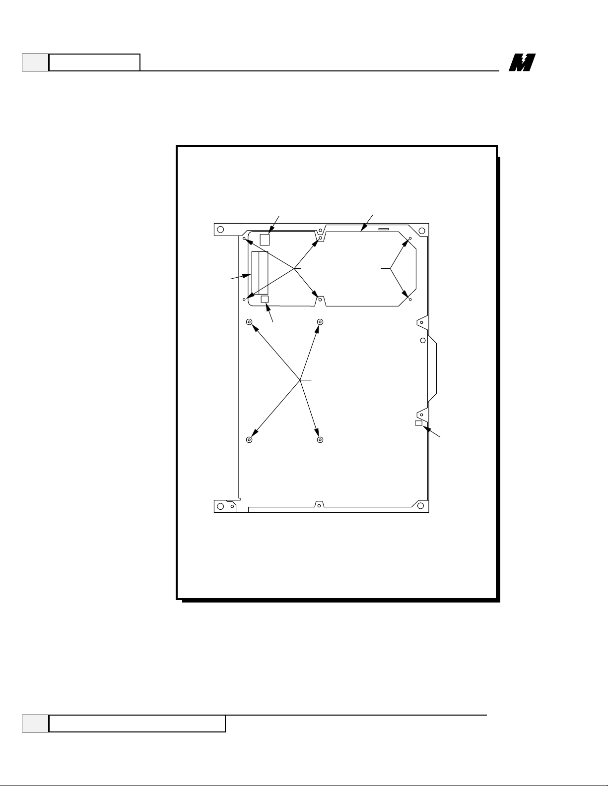
4
Maintenance
84
3/21/96
Replacing the Power Supply
Figure 13. DSD Power Supply Replacement
TB3
TB41
TB42
POWER SUPPLY
MOUNTING SCREWS
DSD DRIVE CONTROL
PCB STANDOFFS
POWER SUPPLY
LATCH
LA-6
Page 89

4
Maintenance
85
3/21/96
Replacing the Power Supply
Replacing the
Power Supply
To replace the DSD power supply , follow this procedure.
CAUTION
The DSD Drive Control PCB has electrostatic sensitive
components. You must follow Electrostatic Discharge (ESD)
procedures to protect the components.
❏ Disconnect all input and output power from the DSD drive.
❏ Remove the DSD Drive Control PCB (see previous procedure).
❏ Note which cables/wires are connected to TB3, TB41, and TB42 on the
DSD Power Supply (see Figure 13). Label any cables/wires, as necessary , to
insure proper reinstallation.
❏ Remove cables/wires from TB3, TB41, and TB42.
❏ Remove six mounting screws (see Figure 13).
❏ Place new power supply on mounting holes.
❏ Fasten the six power supply mounting screws.
❏ Connect cables/wires to TB3, TB41, and TB42.
❏ Replace DSD Drive Control PCB.
❏ Reconnect input and output power.
❏ See Section 3, Operation, for start-up procedure.
WARNING
Before performing any maintenance, disconnect all input
and output power from the DSD drive.
Page 90

4
Maintenance
86
Replacing the DSD Armature Interface PCB
3/21/96
Figure 14. DSD Armature Interface PCB Replacement
CURRENT
SENSOR
NEG GND L1 L2 L3 POS
ARMATURE INTERFACE PCB
Q1 Q3
G2 G1
G2 G1 G2 G1
Q5
(+)
(–)
(N)
THERMISTOR
WIRES
654321
TB6
ALIGNING
PEG
MOUNTING SCREW
(9 TOTAL)
RED
WHT
BLK
J24
E17
E4
E6
E19
TB6
E2
E15
E13
Q4 Q6 Q2
A3
TB4
L1A
L2A
F1 (+)
CONNECTORS FOR
MOTOR ARMATURE
SENSOR FEEDBACK
G1
E21
E8
E23
G2G2G2 G1G1
E10
E12
TB5
LA-101
Page 91

4
Maintenance
87
Replacing the DSD Armature Interface PCB
3/21/96
Replacing the
DSD Armature
Interface PCB
CAUTION
The DSD Armature Control PCB contains electrostatic
sensitive components. You must follow Electrostatic Discharge
(ESD) procedures to protect the components.
To replace the DSD Drive Armature Interface PCB, follow this procedure:
W ARNING
Before performing any maintenance, disconnect all input
and output power from the DSD drive.
❏ Remove all input and output power to the DSD drive.
❏ Locate the Armature Interface PCB. This board is located behind the door
assembly .
❏ Allow the DSD drive to sit for a few seconds to allow the SCRs to discharge.
❏ Remove the J24 connector (see Figure 14).
❏ Remove (unscrew) the wire connectors to the motor armature sensor
feedback wires at TB5 (see Figure 14).
❏ Disconnect the SCRs (Q1 through Q6) gate leads (12 leads) using a needle
nose pliers. Six leads are located on the top and six on the bottom section of
the armature PCB.
❏ Disconnect (unscrew) the thermistor wires at terminals 4 and 5 at TB6 (see
Figure 14).
❏ Disconnect the current sensor (see Figure 14).
❏ Remove the mounting screws (9 screws).
❏ Hold board from top left corner and center bottom and pull out.
❏ Install new board. Line up new board with peg (see Figure 14), and push new
board in making sure not to pinch any wires under the board.
❏ Install the mounting screws (Torque specification of 5-1/2 inch-pounds).
❏ Reconnect the current sensor.
❏ Reconnect the thermistor wires at terminals 4 and 5 at TB6.
Page 92

4
Maintenance
88
Replacing the DSD Armature Interface PCB
3/21/96
❏ Reconnect the SCR gate leads making sure they are not crossed, and are
pushed all the way in (gate leads will first “click” and can then be pushed in
for an additional 1/8” to 1/64”).
❏ Reconnect the Armature sensor feedback wires making sure to observe the
polarity . If these leads are connected in reverse, a Fault 917 (Reverse
Armature Voltage Connection Fault) will occur .
❏ Reconnect the J24 connector.
❏ Apply power to the drive.
Page 93

4
Maintenance
89
Spare Parts List
3/21/96
Description Ref. Design. Qty/Drive Part Number
DSD 406 and 412
Spare Parts List
The parts in Table 5 are replacements for DSD 406 / 412 230 Volt drives.
The parts in Table 6 are replacements for DSD 406 / 412 460 Volt drives.
Table 5. 230 Volt Drives Spare Parts
46S02975-0202
46S03049-0010
-0020
46S02976-0040
46S02976-0010
-0020
-0030
46S03088-0010
46S03046-0010
-0020
-0030
-0040
-0050
-0060
05P00090-0293
46S03020-0010
-0020
-0030
46S03017-0010
46S03089-0010
05P00050-0409
-0410
-0412
05P00050-0446
-0447
46S03214-0010
Drive Control PCBA
Armature Interface PCBA
DSD 406: 1 - 15 HP
20 - 30 HP
40 - 60 HP
DSD 412: 1 - 15 HP
20 - 30 HP
40 - 60 HP
75 - 100 HP
Field Interface PCBA
0.2 - 1.9 A
0.8 - 4.0 A
1.4 - 6.9 A
2.0 - 9.6 A
2.0 - 16 A
5.0 - 24 A
Power Supply PCBA
Snubber PCBA
1 - 7.5 HP
10 - 15 HP
20 - 30 HP
40 - 60 HP
75 - 100 HP (DSD 412 only)
SCR
1 - 15 HP
20 - 30 HP
40 - 60 HP (DSD 412 only)
SCR
40 - 60 HP (DSD 406 only)
SCR
75 - 100 HP (DSD 412 only)
A1
A2
A3
A4
A5
DSD 406: Q1-3
DSD 412: Q1-6
Q1, 3, 5
Q2, 4, 6
Q1-12
1
1
1
1
1
DSD 406: 3
DSD 412: 6
3
3
12
Page 94

Description Ref. Design. Qty/Drive Part Number
4
Maintenance
90
3/21/96
Table 5. 230 Volt Drives Spare Parts - Continued
None
05P00016-0048
-0012
-0008
05P00217-0015
-0014
-0013
-0012
-0020
05P00050-0442
05P00017-0387
-0349
-0226
-0227
-0155
-0228
-0166
-0179
-0220
-0234
05P00017-0387
-0349
-0243
-0227
-0155
-0178
-0166
-0179
-0220
-0366
-0234
-0235
See Table 7
See Table 8
Fan / Guard
1 - 10 HP
15 - 30 HP
40 - 60 HP
75-100 HP (DSD 412 only)
Current Transducer
1 - 7.5 HP
10 - 15 HP
20 - 30 HP
40 - 60 HP
75 - 100 HP (DSD 412 only)
Field Power Module
AC Line Fuse
1 HP (10 A)
1.5 - 2 HP (12 A)
3 - 5 HP (35 A)
7.5 - 10 HP (50 A)
15 HP (70 A)
20 - 25 HP (125 A)
30 HP (150 A)
40 - 50 HP (200 A)
60 HP (200 A)
75 - 100 HP (400 A) (DSD 412 only)
DC Bus Fuse (DSD 412 Only)
1 HP (10 A)
1.5 HP (12 A)
2 HP (15 A)
3 - 5 HP (50 A)
7.5 - 10 HP (70 A)
15 HP (100 A)
20 - 25 HP (150 A)
30 HP (200 A)
40 - 50 HP (250 A)
60 HP (300 A)
75 HP (400 A)
100 HP (500 A)
Burden Resistor
Power Range Resistor
B1
U1
Q7
F1-3
F4
R4
R5
1
1
1
3
1
1
1
Spare Parts List
Page 95

4
Maintenance
91
3/21/96
Spare Parts List
Description Ref. Design. Qty/Drive Part Number
Table 6. 460 Volt Drives Spare Parts
46S02975-0202
46S03049-0010
-0020
46S02976-0040
46S02976-0010
-0020
-0030
46S03088-0010
46S03046-0010
-0020
-0030
-0040
-0050
-0060
05P00090-0293
46S03020-0010
-0020
-0030
46S03017-0010
46S03089-0010
05P00050-0409
-0410
-0412
05P00050-0446
-0447
46S03214-0010
None
05P00016-0048
-0012
-0008
Drive Control PCBA
Armature Interface PCBA
DSD 406: 2 - 30 HP
40 - 60 HP
75 - 125 HP
DSD 412: 2 - 30 HP
40 - 60 HP
75 - 125 HP
150 - 200 HP
Field Interface PCBA
0.2 - 1.9 A
0.8 - 4.0 A
1.4 - 6.9 A
2.0 - 9.6 A
2.0 - 16 A
5.0 - 24 A
Power Supply PCBA
Snubber PCBA
2 - 15 HP
20 - 30 HP
40 - 60 HP
75 - 125 HP
150 - 200 HP (DSD 412 only)
SCR
2 - 30 HP
40 - 60 HP
75 - 125 HP (DSD 412 only)
SCR
75 - 125 HP (DSD 406 only)
SCR
150 - 200 (DSD 412 only)
Fan
2 - 25 HP
30 - 60 HP
75 - 125 HP
150 - 200 HP (DSD 412 only)
A1
A2
A3
A4
A5
DSD 406: Q1-3
DSD 412: Q1-6
Q1, 3, 5
Q2, 4, 6
Q1-12
B1
1
1
1
1
1
DSD 406: 3
DSD 412: 6
3
3
12
1
Page 96

Description Ref. Design. Qty/Drive Part Number
4
Maintenance
92
3/21/96
Table 6. 460 Volt Drives Spare Parts - Continued
05P00217-0015
-0014
-0013
-0012
-0020
05P00050-0442
05P00017-0387
-0349
-0226
-0227
-0155
-0228
-0166
-0179
-0220
-0234
05P00017-0387
-0349
-0243
-0227
-0155
-0178
-0166
-0179
-0220
-0366
-0234
-0235
See Table7
See Table 8
1
1
3
1
1
1
Spare Parts List
Current Transducer
2 - 15 HP
20 - 30 HP
40 - 60 HP
75 - 125 HP
150 - 200 HP (DSD 412 only)
Field Power Module
AC Line Fuse
2 HP (10 A)
3 - 5 HP (12 A)
7.5 - 10 HP (35 A)
15 - 20 HP (50 A)
25 - 30 HP (70 A)
40 - 50 HP (125 A)
60 HP (150 A)
75 - 100 HP (200 A)
125 HP (200 A)
150 - 200 HP (400 A) (DSD 412 only)
DC Bus Fuse (DSD 412 Only)
2 HP (10 A)
3 HP (12 A)
5 HP (15 A)
7.5 - 10 HP (50 A)
15 - 20 HP (70 A)
25 - 30 HP (100 A)
40 - 50 HP (150 A)
60 HP (200 A)
75 - 100 HP (250 A)
125 HP (300 A)
150 HP (400 A)
200 HP (500 A)
Burden Resistor
Power Range Resistor
U1
Q7
F1-3
F4
R4
R5
Page 97

4
Maintenance
93
3/21/96
Burden Resistor List
HP Rating
230V 460V Part No. Description Qty. Ref. Design.
1 2 05P00225-2250 64.9 ohms, 1% metal film, 1/4 Watt. 1 R4
1.5 3 05P00225-2250
2 5 05P00225-2260 76.8 ohms, 1% metal film, 1/4 Watt. 1 R4
3 7.5 05P00225-2260
5 10 05P00225-2260
7.5 15 05P00225-2260
10 20 05P00225-1610 38.3 ohms, 1% metal film, 1/4 Watt. 1 R4
— 25 05P00225-1610
15 30 05P00225-1610
20 40 05P00225-3600 9.53 ohms, 1% metal film, 1/4 Watt. 1 R4
25 50 05P00225-3600
30 60 05P00225-3600
40 75 05P00041-0703 4.32 ohms, 1% metal film, 3 Watt. 1 R4
50 100 05P00041-0703
60 125 05P00041-0703
75 150 05P00225-1992 20.0 ohms, 1% metal film, 1 Watt. 1 R4
100 200 05P00225-0022 15 ohms, 1% metal film, 1 Watt. 1 R4
Table 7. Burden Resistor
Page 98

4
Maintenance
94
Power Range Resistor List
3/21/96
HP Rating
230V 460V Part No. Description Qty. Ref. Design.
1 2 05P00225-2060 26.7 ohms, 1% metal film, 1/4 Watt. 1 R5
1.5 3 05P00225-2060
2 5 05P00225-2300 86.6 ohms, 1% metal film, 1/4 Watt. 1 R5
3 7.5 05P00225-2300
5 10 05P00225-2770 196 ohms, 1% metal film, 1/4 Watt.
7.5 15 05P00225-2770
10 20 05P00225-0200 332 ohms, 1% metal film, 1/4 Watt. 1 R5
— 25 05P00225-0200
15 30 05P00225-0200
20 40 05P00225-0230 499 ohms, 1% metal film, 1/4 Watt. 1 R5
25 50 05P00225-0230
30 60 05P00225-0230
40 75 05P00225-3590 715 ohms, 1% metal film, 1/4 Watt. 1 R5
50 100 05P00225-3590
60 125 05P00225-3590
75 150 05P00225-3780 953 ohms, 1% metal film, 1/4 Watt. 1 R5
100 200 05P00225-3790 1.27 K ohms, 1% metal film, 1/4 Watt. 1 R5
Table 8. Power Range Resistor
Page 99

Glossary
95
Glossary
3/21/96
Glossary
A/D – Analog to Digital converter.
Active Hub – A central component in LAN star networks that ensures data
integrity over distances of up to 2000 feet by regenerating the network signal.
Active menu item – The menu item for an RDU that will be used to get the
source of the information to be displayed. When a menu item number is
selected, the Control/Display Unit (CDU) menu item data will be used; if there is
no data in the CDU menu item for the selected menu item number, then the
default menu item data is used.
Active Link – A device that interconnects two LAN bus networks.
ANIO – Remote Analog I/O [Input/Output] PCB.
Broadcast message – A type of LAN message which is capable of being
received by all nodes on the LAN. The message contains the source of the
message, but the destination is all nodes that have been enabled to receive
broadcast messages.
CDU – Control/Display Unit. There are two CDUs supported for the MicroTrac
DSD drive: the Standard CDU (see SCDU definition) and the Portable CDU (see
PCDU definition).
CDU menu item – A menu item of an RDU that was built by using the PCDU.
Channel – The second level address used to further define the location of
information external to the the PAC environment (the first level of addressing
being the Node number - see NODE definition). To access information external
to the PAC environment requires reference to that information by an address
which includes all levels of addressing defined for that particular information.
That is, to use a Channel number also requires the associated Node number such
as Node 50, Channel 21. The system will support a maximum of 256 (0 through
255) Channel numbers.
Complex PAC task – Any of the more complicated PAC functions (as opposed
to the simpler elemental functions), which consists of two (or more) interrelated
PAC tasks. These interrelated tasks are referred to as segments. Each segment is
a self-contained module which executes sequentially , although each segment
executes separately . The interrelated segments exchange information between
each other which has predefined significance. The various segments need not be
programmed in a common scan (see SCAN definition).
An example of a complex task would be SPDR, the speed regulator task, which
consists of two related segments. One segment executes in the fast scan, and
consists of the actual function of regulating the speed by comparing the speed
Page 100

Glossary
96
Glossary
3/21/96
reference to the feedback and generating a torque command based on the
difference and the required gains of the regulator. The other segment consists of
the code used to calculate the gains required for the speed regulation function in
the format required by that segment. In other words, it translates from the
engineering terms used to describe regulator performance (such as load inertia
and desired crossover frequency) to the integral and proportional gains required
by the regulator segment. Since these defining parameters are rarely changed,
this segment needs to execute only rarely , thus saving processor time for other
functions which do require frequent execution.
Conditional scan – Conditional scan tasks define sub-programs (i.e. subprograms consisting of unique interconnections of PAC tasks) which execute
only when certain logic conditions related to the conditional scan task are
satisfied. When the conditional scan executes, the program defined for the
conditional scan executes at the scan level at which the conditional scan task is
programmed (see SCAN definition). The use of conditional scans allows greater
utilization of the limited processor time.
Custom fault – A fault (or error) defined via the PAC task “FLTD”. These
faults have significance only to a particular PAC design. (See Fault or Err or
definition).
D/A – Digital to Analog converter.
DCU – Drive Control Unit. The drive control unit refers to the hardware and
software used to control the drive as opposed to the hardware and software used
to control the power conversion process. Specifically , it refers to the hardware
and software associated with the DCU microprocessor. The DCU software
includes the variable
software generated as a result of the PAC program and the
fixed
software (see Kernel definition) used to control execution of the PAC
program.
Default menu – A menu for an RDU that contains the default menu items as
received through the LAN from the drives. Each drive connected to the LAN
can have default menu items that are to be displayed on specific RDUs. The
default menu items and the order of the menu items are determined by the PAC
programmer.
Directed message – A type of LAN message which can be received only by one
LAN Node. This type of message contains both the source and destination Node
numbers.
Elemental PAC task – The simpler PAC language functions where everything
associated with that function is contained in one sequentially executed module.
 Loading...