

Page 1

For GPD 515/G5 and GPD 503
Adjustable Frequency Drives
ANALOG SPEED REFERENCE (UNIPOLAR) (AI-14U)
MODEL DS386
Before installing this option, a TECHNICALLY QUALIFIED INDIVIDUAL, who is familiar with this type of
equipment and hazards involved, should READ this ENTIRE INSTRUCTION SHEET.
IMPORTANT
This option may have been installed by the factory. However, certain steps can
only be completed at the installation site. Therefore, review and then perform
those steps which complete the installation process.
INTRODUCTION
When installed, this option allows the user to interface a high resolution (14-bit) analog speed reference to the
GPD 515/G5 or GPD 503. This reference can be either voltage (0-10V) or current (4-20mA). Frequency
command gain and bias are adjusted by programming settings in the drive.
CAUTION
The option card uses CMOS IC chips. If proper electrostatic discharge (ESD)
protective procedure is not used when handling the card, the ICs may be damaged,
resulting in erratic performance of the drive.
INSTALLATION
1. Disconnect all electrical power to drive.
2. Remove drive front cover. Check that CHARGE indicator lamp inside drive is off.
3. Verify voltage has been disconnected by using a voltmeter to check for voltage at incoming power terminals
(L1, L2, L3).
WARNING
HAZARDOUS VOLTAGE CAN CAUSE SEVERE INJURY OR
DEATH. LOCK ALL POWER SOURCES FEEDING DRIVE IN
"OFF" POSITION.
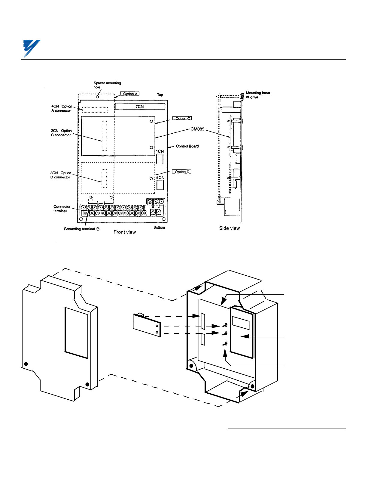
NOTE: If this option is being installed on a GPD 515/G5 with speed feedback, the speed feedback card needs
to be temporarily un-installed to allow access to the connector 2CN on the Drive’s Control Board and TC1, TC2
& TC3 on the AI-14U option card.
4. See Figure 1 (GPD 515/G5) or Figure 2 (GPD 503). Install the option on the Main Control Board, 1PCB, and
ensure 2CN is properly connected. Make sure Electrostatic procedure is followed.
Yaskawa Electric America, Inc . www.drives.com
02Y00025-0295 Page 1 OF 5
REL. 02/8/91
Page 2
ANALOG SPEED REFERENCE
MODEL DS386
Figure 1. Installation of Analog Speed Reference (AI-14U) in GPD 515/G5
FRONT
COVER
2CN
ANALOG
SPEED REF.
3CN
OPTION
BOARD
Figure 2. Installation of Analog Speed Reference (AI-14U) in GPD 503
MAIN
CONTROL
BOARD
DIGITAL
OPERATOR
PLASTIC
STANDOFFS
ON MAIN
BOARD
Yaskawa Electric America, Inc . www.drives.com
02Y00025-0295 Page 2 OF 5
REL. 02/8/91
Page 3

ANALOG SPEED REFERENCE
Table 1. Specifications of AI-14U Card
Parameter Value
Input Signal Level 0 to 10V DC (Input Impedance: 20kΩ)
4 to 20mA (Input Impedance: 250Ω)
Input Resolution 14 bits (1/16384)
Control voltage input (from GPD 515/G5 or GPD 503): 24V (isolated)
5. Wiring. See Figure 3 for Analog Speed Reference connections. See Table 2 for terminal functions.
Table 2. Terminal Functions of AI-14U
Terminal Function Signal Level Notes
TC1 Analog voltage input Input voltage: 0 to 10V — Input Resolution: 1/16384
Input Impedance: 20kΩ (14 bits)
TC2 Analog current input Input current: 4 to 20mA
Input Impedance: 250Ω
TC3 Signal common 0V — Terminal screws are metric size M3.
— Signal Linearity: ±0.1%
MODEL DS386
CAUTION
KEEP ANALOG SPEED REF. (I.E. CONTROL CIRCUIT) WIRING
SEPARATE FROM MAIN CIRCUIT INPUT/OUTPUT WIRING.
CAUTION
TO PREVENT ERRONEOUS OPERATION CAUSED BY NOISE
INTERFERENCE, USE SHEILDED CABLE FOR CONTROL
WIRING, AND LIMIT DISTANCE TO 10M (33 FEET) OR LESS.
IMPORTANT
Because the analog speed reference is converted by 1/16384 resolution, the
voltage source accuracy of the analog speed reference source must be considered. To ensure speed control accuracy, use a high precision power supply for
the voltage source.
Route wires from the drive and connect to the peripheral device. Refer to "Electrical Installation" in the drive’s
technical manual for further information on use of shielded cable.
Yaskawa Electric America, Inc . www.drives.com
02Y00025-0295 Page 3 OF 5
REL. 02/8/91
Page 4

GPD
503
ANALOG SPEED REFERENCE
MODEL DS386
FREQ. REF.
UNIT *
0-10V
4-20mA
0V
* USE HIGH ACCURACY VOLTAGE
REGULATOR FOR FREQ. REF. UNIT
10K ohm
TC1
10K ohm
TC2
250 ohm
TC3
SHIELD
MCCB
AI-14U BOARD
20K ohm
2uF20K ohm
10K ohm
2uF
0V
L1
L2
L3
2CN 2CN
0V
12
GPD
515
or
(GPD 503)
(GPD 515)
T1
T2
T3
MOTOR
I M
E
Figure 3. Interconnection for Analog Speed Reference (AI-14U) Circuit
7. Adjustments. There are no adjustments to be made on the Analog Speed Reference option; however, the
drive will have to be reprogrammed for the input requirement of the remote device.
A. GPD 515/G5: See Table 3 and Figure 4.
IMPORTANT
For the Analog Speed Reference circuit to function properly, parameter b1-01
must be set to " 3 " (input to AI-14U replaces auto speed reference signal).
Table 3. Adjustments of Input Signal Gain and Bias for GPD 515/G5
GPD 515/G5
Function
Setting
Increment Factory Setting
Parameter Range
H3-02 Frequency command 0.0 to 1000.0% 0.1 % 10V/100.0%
gain (10V/xx%)
H3-03 Frequency command -100 to 100% 1 % 0%
bias
Yaskawa Electric America, Inc . www.drives.com
02Y00025-0295 Page 4 OF 5
REL. 02/8/91
Page 5

ANALOG SPEED REFERENCE
MODEL DS386
H3-02 H3-02
GAIN GAIN
H3-03
(+)
FREQ.
CMD
(%)
H3-03
(–)
0
0V
BIAS BIAS
10V 20mA
SPEED
REF.
INPUT
H3-03
(+)
FREQ.
CMD
(%)
H3-03
(–)
0
4mA
SPEED
REF.
INPUT
Figure 4. Frequency Command Gain and Bias Adjustments for GPD 515/G5
B. GPD 503: See Table 4 and Figure 5.
IMPORTANT
For the Analog Speed Reference circuit to function properly, system constant Sn-04 must be set to XXX0 and
Sn-08 must be set to XXX 0. The input to AI-14U replaces the auto speed reference signal (Terminal 13).
7. Reinstall and secure drive cover.
Table 4. Adjustments of Input Signal Gain and Bias for GPD 503
GPD 503
Function
Setting
Increment Factory Setting
Constant Range
bn-05 Frequency command 0.0 to 1000.0% 0.1 % 10V/100.0%
gain (10V/xx%)
bn-06 Frequency command -100 to 100% 1 % 0%
bias
GAIN GAIN
bn-05 bn-05
bn-06
(+)
FREQ.
CMD
(%)
0
0V
BIAS BIAS
10V 20mA
SPEED
FREQ.
CMD
(%)
REF.
bn-06
INPUT
(–)
Figure 5. Frequency Command Gain and Bias Adjustments for GPD 503
8. Place this instruction sheet with the drive technical manual.
THIS COMPLETES INSTALLATION OF THIS OPTION.
bn-06
(+)
bn-06
(–)
0
4mA
SPEED
REF.
INPUT
Yaskawa Electric America, Inc . www.drives.com
02Y00025-0295 Page 5 OF 5
REL. 02/8/91
 Loading...