

Page 1

DriveWizard Plus
Instruction Manual
To properly use the product, read this manual thoroughly and retain
for easy reference, inspection, and maintenance. Ensure the end user
receives this manual.
MANUAL NO. TOEP C730600 20H
Page 2

Table of Contents
Safety Symbols and Markings.........................................................................................................4
Manual Overview.............................................................................................................................5
Related Manuals..............................................................................................................................5
s on Da
Note
About this Software.......................................................................................................................... 5
Safety Notes and Instructi
1 System Over
1.1 DriveWizard Pl
1.2 System Environment.................................................................................................. 9
1.3 Installing Drive
1.4 Uninstalling D
2 Starting DriveWizar
2.1 Starting the Program ............................................................................................... 16
2.1.1 Startin
2.1.2 Starting from a Shortcut................................................................................................16
2.1.3 Double-clicking on a Project
2.2 Connecti
2.3 Connecting the Drive and PC.................................................................................... 19
2.4 Connecting Via an Upper Contro
2.4.1 Ethernet/Ethernet (LP) Connection..............................................................................22
2.4.2 Other Communication Protocols Besides Ethernet/Ethernet (LP).............................. 29
2.5 Managing P
2.5.1 Starting DriveWizard Plus............................................................................................. 33
2.5.2 Double-clicking on a Project File from Windows Explorer...........................................34
2.5.3 Op
2.5.4 Closing a
2.5.5 Connecting
2.5.6 Disconnecting the Drive................................................................................................39
2.5.7 Saving a P
2.5.8 Save Proje
2.5.9 Quitting
2.5.10 Managing Project Files with the Menu .........................................................................42
3 Drive
3.1 Screen Construction
3.1.1 Title Bar ......................................................................................................................... 45
3.1.2 Main Menu .................................................................................................................... 46
3.1.3 Toolbars
3.1.4 Caption Bar
3.1.5 Tree Window.................................................................................................................52
3.1.6 Chil
3.1.7 Docking Windows and Floating Windows ...................................................................56
ta Communicati
view....................................................................................................... 7
g from the Start Menu.........................................................................................16
ng the Drive and PC via the Com
roject Fi
ening a Project File .................................................................................................. 36
Project File .................................................................................................... 37
roject File ..................................................................................................... 40
ct File As......................................................................................................41
the Application .................................................................................................42
Wizard Pl
.........................................................................................................................49
d Windo
ons ..................................................................................................... 5
ons..........................................................................................................6
us Overview and Functions .................................................................. 7
Wizard Plus....................................................................................... 11
riveWizard Plus ................................................................................... 15
d Plus......................................................................................... 16
File ..................................................................................16
Port ......................................................... 17
ller.......................................................................... 21
les ............................................................................................. 32
the Drive to the PC.................................................................................... 38
us Main Screen.................................................................................. 43
................................................................................................. 44
...................................................................................................................51
w ................................................................................................................ 54
2
Page 3

3.1.8 Status Bar......................................................................................................................57
4 Editing Drive Data.................................................................................................... 58
4.1 Drive Model Data Display......................................................................................... 58
4.2 Parameter Edit......................................................................................................... 59
4.2.1 Parameter Edit Window................................................................................................59
4.2.2 Direct Parameter Edit....................................................................................................87
4.2.3 Comment Edit ...............................................................................................................88
4.3 Troubleshooting....................................................................................................... 89
4.3.1 Current Fault .................................................................................................................90
4.3.2 Fault History Display.....................................................................................................90
4.3.3 Clearing the Fault History .............................................................................................91
4.3.4 Updating the Fault History ............................................................................................92
4.3.5 Saving the Fault History................................................................................................ 92
4.3.6 Reading the Fault History .............................................................................................93
4.4 Monitor ................................................................................................................... 94
4.4.1 All Monitors....................................................................................................................94
4.4.2 User Monitor................................................................................................................ 100
4.4.3 I/O Monitor................................................................................................................... 109
4.4.4 Status Monitor .............................................................................................................113
4.4.5 Movement Monitor......................................................................................................115
4.4.6 Oscilloscope................................................................................................................124
4.4.7 V
4.5 A
4.5.1 Selecting the Right Type of Auto-Tuning Mode.........................................................147
4.5.2 Warning Messages.....................................................................................................154
4.5.3 Tuning Parameter Setting Screen..............................................................................167
4.5.4 Auto-Tuning Screen....................................................................................................168
4.6 Test Run.................................................................................................................170
4.6.1 Manual Operation .......................................................................................................170
4.6.2 Pattern Operation........................................................................................................174
4.7 Drive Replacement .................................................................................................179
4.7.1 Drive Replacement and Model Matching...................................................................180
4.7.2 Selecting the Replacement Drive...............................................................................182
4.7.3 Parameter Conversion................................................................................................189
4.7.4 Checking the Results from Convert Parameter.........................................................192
4.7.5 After Parameter Conversion.......................................................................................193
4.7.6 Displaying Data Needed for Drive Replacement.......................................................193
5 DriveWizard Plus Database Update Utility ................................................................194
5.1 Opening a Database Update Utility..........................................................................194
5.1.1 Starting a Session of DriveWizard from the Start Menu............................................194
5.2 Regi
Revision History........................................................................................................................197
isual Monitor..............................................................................................................140
uto-Tuning for Drive and Motor Parameters ...........................................................145
stering New Software Data...............................................................................195
3
Page 4
Safety Symbols and Markings
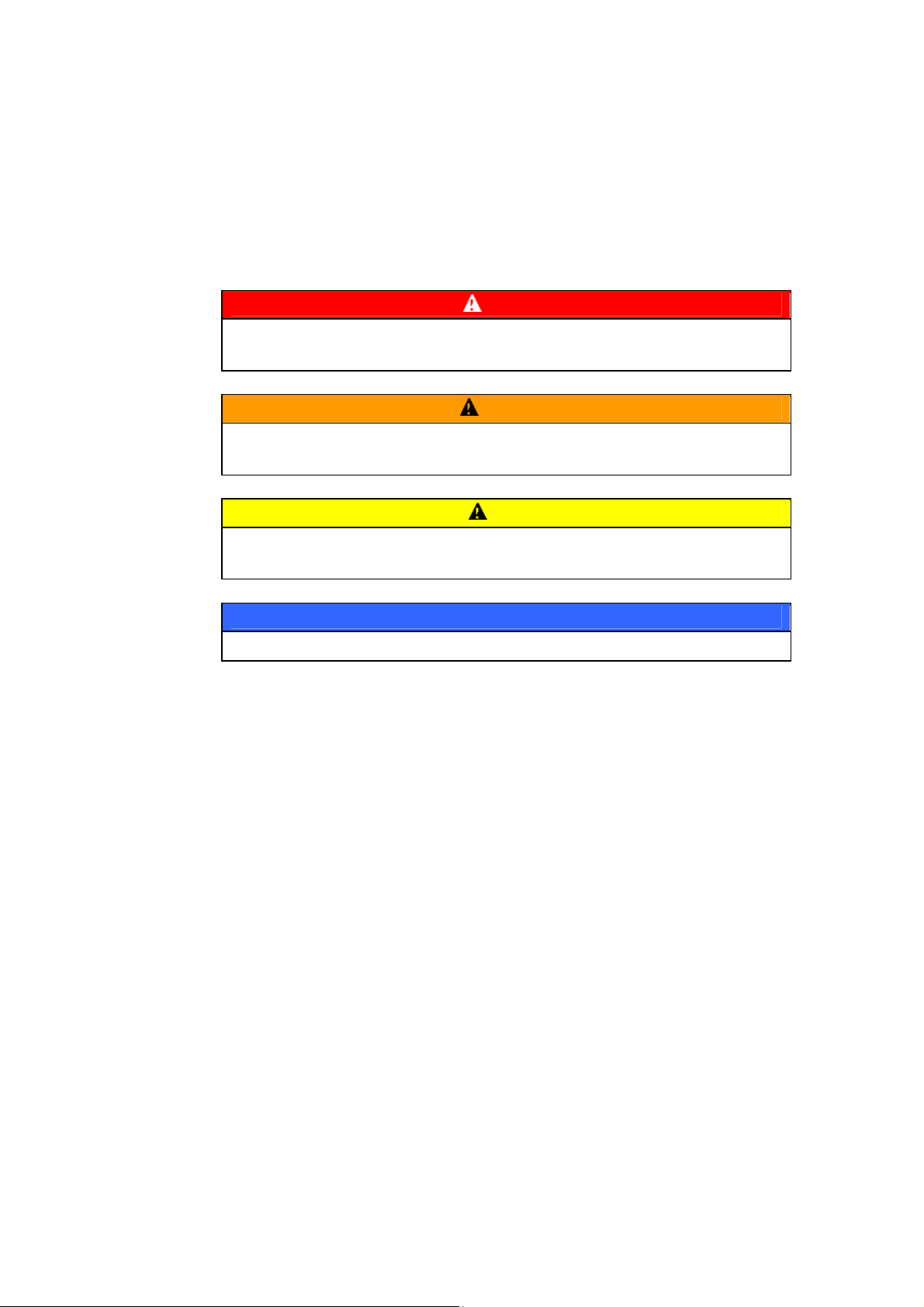
The following conventions are used to indicate and classify safety precautions in this manual.
Always heed the information provided with them. Failure to heed precautions can result in injury to
people or damage to property.
DANGER
Indicates an imminently hazardous situation which, if not avoided, will result in death
or serious injury.
Indicates a potentially hazardous situation which, if not avoided, could result in
death or serious injury.
Indicates a potentially hazardous situation which, if not avoided, may result in minor
or moderate injury, or property damage.
WARNING
Caution
Important
Indicates a property damage message.
4
Page 5

Manual Overview
This manual has been written for those using DriveWizard Plus. Information covered in this manual
includes:
• An overview of all functions used in DriveWizard Plus
• Instructions for installing and uninstalling DriveWizard Plus.
Related Manuals
Detailed technical documentation is available on Yaskawa drives and various drive options. Refer to
this other documentation as needed.
Make sure that you have a proper understanding of all product specifications and restrictions when
using this product.
Notes on Data Communications
Important
・ DriveWizard Plus is not for use with any other communication-related devices not
specified in this manual. Do not make any modifications to the drive, operator,
software, or MEMOBUS/Modbus data.
Use of any other communication devices will involve data that does not agree or
comply with DriveWizard Plus programming, and may not operate properly.
About this Software
Notes on Usage
• This software is for installation to a single computer only. Authorization is required for use on
another computer
• It is strictly forbidden to copy the software for any purpose other than as backup
• Store the CD-ROM in a safe, secure location
• It is strictly forbidden to reverse compile or reverse engineer this software
• It is strictly forbidden to loan, exchange, or trade this software to a third party
• Yaskawa Electric possesses all rights of copyright protection related to this software.
5
Page 6
Operating System and Trademarks
・ Windows 2000, Windows XP, Windows Vista, and Windows 7 registered trade marks of
Microsoft Incorporated.
・ MECHATROLINK is a trademark of the MECHATROLINK Members Association.
・ Adobe Reader is a registered trademark of Adobe Systems Incorporated.
・ Pentium is a registered trademark of Intel Corporation.
・ Ethernet is a registered trademark of Xerox Corporation.
・ InstallShield is a registered trademark of InstallShield Software Corporation.
・ Registered trademarks used in this manual do no appear with TM and ® .
Safety Notes and Instructions
Below is a list of important wiring instructions that must be followed carefully for safety and proper
performance:
Cautionary Notes on Wiring
Note
・ Use the proper cable when connecting the drive and DriveWizard Plus. Close
and restart DriveWizard Plus if the cable is inserted during a session of
DriveWizard Plus.
Using any other type of cable will void the warranty for the drive and software.
Notes on Use
Note
・ Close and restart DriveWizard Plus if the power to the drive is turned off and then
turned on.
Failing to do so will void the warrantee for the drive and software
.
6
Page 7

1 System Overview
This section provides an overview of DriveWizard Plus and various features of the software
1.1 DriveWizard Plus Overview and Functions
DriveWizard Plus is a powerful engineering tool designed for advanced application setup and for
performing maintenance tasks on a Yaskawa drive.
The advanced functionality of DriveWizard Plus assists all users with powering up the drive, test
running the application, or performing maintenance.
Main functions:
・ Editing parameters while taking advantage of useful help information
・ Displaying drive operation status (I/O signals, internal status information, etc.) as well as product
information
・ Troubleshooting features, including possible causes for problems and other help options
・ Test running the drive and application (both manual and pattern operation)
・ Auto-Tuning features to optimize parameter settings
・ Oscilloscope function.
NOTE: Some DriveWizard Plus functions may not be applicable for the specific drive model
being used. Such functions will not be available when displayed in the menu toolbars.
There are two ways to connect the drive to DriveWizard Plus.
Normal Connection (Drive Only)
Connects the drive directly to DriveWizard Plus using an RS-232C communications cable.
To connect a different drive, unplug the communications cable from the drive that is currently
connected and connect it to the other drive.
Controller Connection
DriveWizard Plus can also operate a drive running from an upper controller using a
MECHATROLINK communication cable.
Connecting DriveWizard Plus to an upper controller makes it possible for DriveWizard Plus to
operate multiple drives running on the same network, without needing to switch or connect new
serial communication cables.
7
Page 8
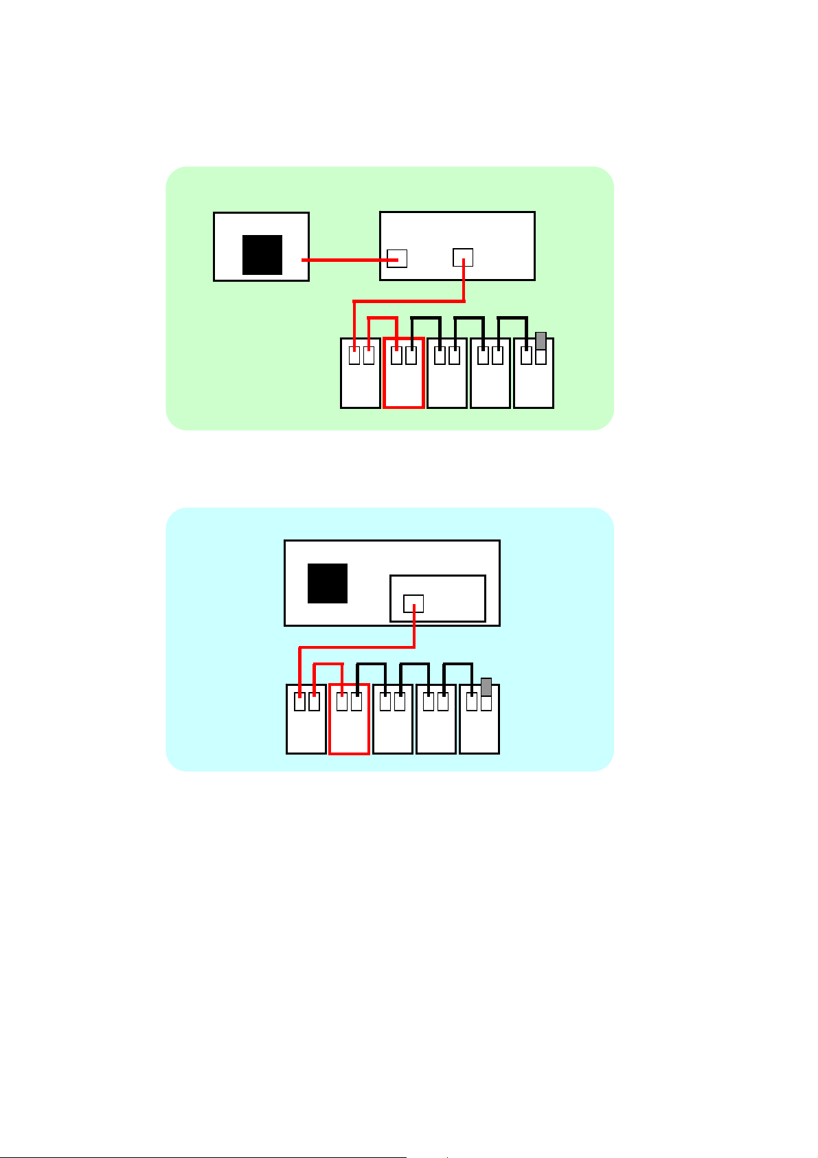
<Ethernet / Ethernet (LP) Connection>
r
r
PC
DriveWizard Plus
Ethernet
Ethernet (LP)
MECHATROLINK-II communication cable
<MP2100 / MP2100M Connection>
DriveWizard Plus
MECHATROLINK-II communication cable
Drive Drive Drive Drive Drive
Controlle
(MP2200/MP2310/MP2300S/MP2400)
M-II
Drive Drive Drive Drive Drive
PC
Controlle
(MP2100/MP2100M)
M-II
8
Page 9

1.2 System Environment
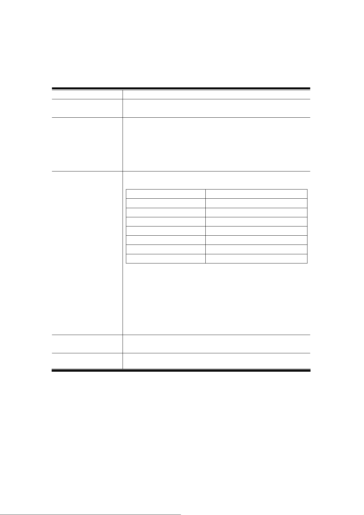
System requirements for running DriveWizard Plus are listed in the table below:
PC PC/AT DOS/V compatible PCs
*Yaskawa will not provide support when using NEC PC9821 series computers.
CPU Pentium 1 GHz or higher (1.6 GHz recommended)
RAM 1 GB or more
Hardware Disk Space At least 100 MB (400 MB recommended at time of installation)
Screen Resolution
Color Display 65535 colors (16 bit) or higher
OS English or Japanese OS
Drive and PC Connection
Cable
Other More than one node requires a separate RS-232C, RS-422, or RS-485 interface.
XGA monitor (at least 1024×768 set for small fonts)
OS compatible with 32-bit memory
・Windows 2000 (Service
OS compatible with 32-bit and 64-bit memory
・Windows 7
Yaskawa provides a RS-232C communications cable.
Drive Model Cable Model
Yaskawa cable
Other cable types
・SI-232/J7 option card required if using VS mini J7.
・SI-232/JC option card required if using J1000.
・If using RS-422 or RS-485, be sure to use the proper cable included and perform all wiring as
specified in the product manual and the technical manual.
CD-ROM (for installation only)
Adobe Acrobat Reader 6.0
*Required for displaying Help information
Pack 1 or later), Windows XP, Windows Vista
G5 Socket Connector Type
W5250
A1000, V1000,
J1000, G7, F7, V7,
J7, and Others
G5 Socket Connector Type
A1000, V1000,
J1000, G7, F7, V7,
J7, and Others
Modular Connector Type
WV103
UWR100-1
UWR103-1w/FLASH write cable
Modular Connector Type
UWR00468-2
UWR00468-1 with FLASH write cable
NOTE: To install and uninstall DriveWizard Plus, the user must be logged in with
administrator rights.
NOTE: Windows XP, Windows Vista, and Windows 7 users should take note of the
following: Multiple users cannot log in simultaneously; only one user is allowed at a time.
NOTE: Some security and virus software may interfere with DriveWizard Plus and keep it
from starting properly.
9
Page 10
■Connectin
System configuration requirements are listed bel
g to an Upper Controller
ow for connecting DriveWizard Plus to an upper
controller.
DriveWizard Plus Ver. 3.00.0028 or later
Serial Communication
Ethernet, PCI bus
Interface
Engineering Tools
MPE720
MPE720 Ver. 6 (Ver. 6.30 or later)
MPE720 Ver. 6 Lite (Ver. 6.30 or later)
NOTE: For information on installation and other operations, refer to
Engineering Tool for MP2000 Series Machine Controller MPE
720 Version 6 USER’S MANUAL (manual No.: SIEP C880700
30).
Controller Machine Controller MP2000 Series
MP2100/MP2100M, MP2200(CPU-03/04), MP2310, MP2300S, MP2400
Controller Software Version
MP2100 Ver. 2.76 or later
MP2100M *1 Ver. 2.76 or later
MP2200 CPU-03 *1 Ver. 2.76 or later
MP2200 CPU-04 *1 Ver. 2.76 or later
MP2310 *1 Ver. 2.76 or later
MP2300S *1 Ver. 2.76 or later
MP2400 Ver. 2.76 or later
*1
Using the SVB-01 module requires that the SVB-01 software be Ver. 1.25 or later.
• Make sure the message communication function is enabled in the MECHATROLINK
master when connecting to an upper controller in addition to the following settings:
• Set the number of node address restarts to greater than 1.
• The number of nodes set for restart must be greater than the number of restarts
allowed:
(Number of restart nodes) – (Number of restarts allowed) > 1
Communications Option SI-T3 Ver. 6104 or later
SI-T3/V Ver. 6104 or later
Drive Set the MECHATROLINK communication speed to 10 Mbps (parameter F6-22 = 0).
10
Page 11
1.3 Installing DriveWizard Plus
Executing the DriveWizard Plus installation program will install the software. All files needed to install
the software are included on the CD-ROM.
For proper software installation, be sure that all other programs have been closed.
NOTE: To install DriveWizard Plus, the user must be logged in with administrator rights.
Follow the instructions below to install DriveWizard Plus:
1) Insert the CD into the CD-ROM drive. If the PC is set for autoplay, the installation program will
open immediately. If the PC is not set for autoplay, follow the directions below to install
DriveWizard Plus:
a) From the Start menu, select “Run,” then enter “D: ¥SETUP.EXE” (the path for the CD drive).
Click “OK”.
b) From Windows
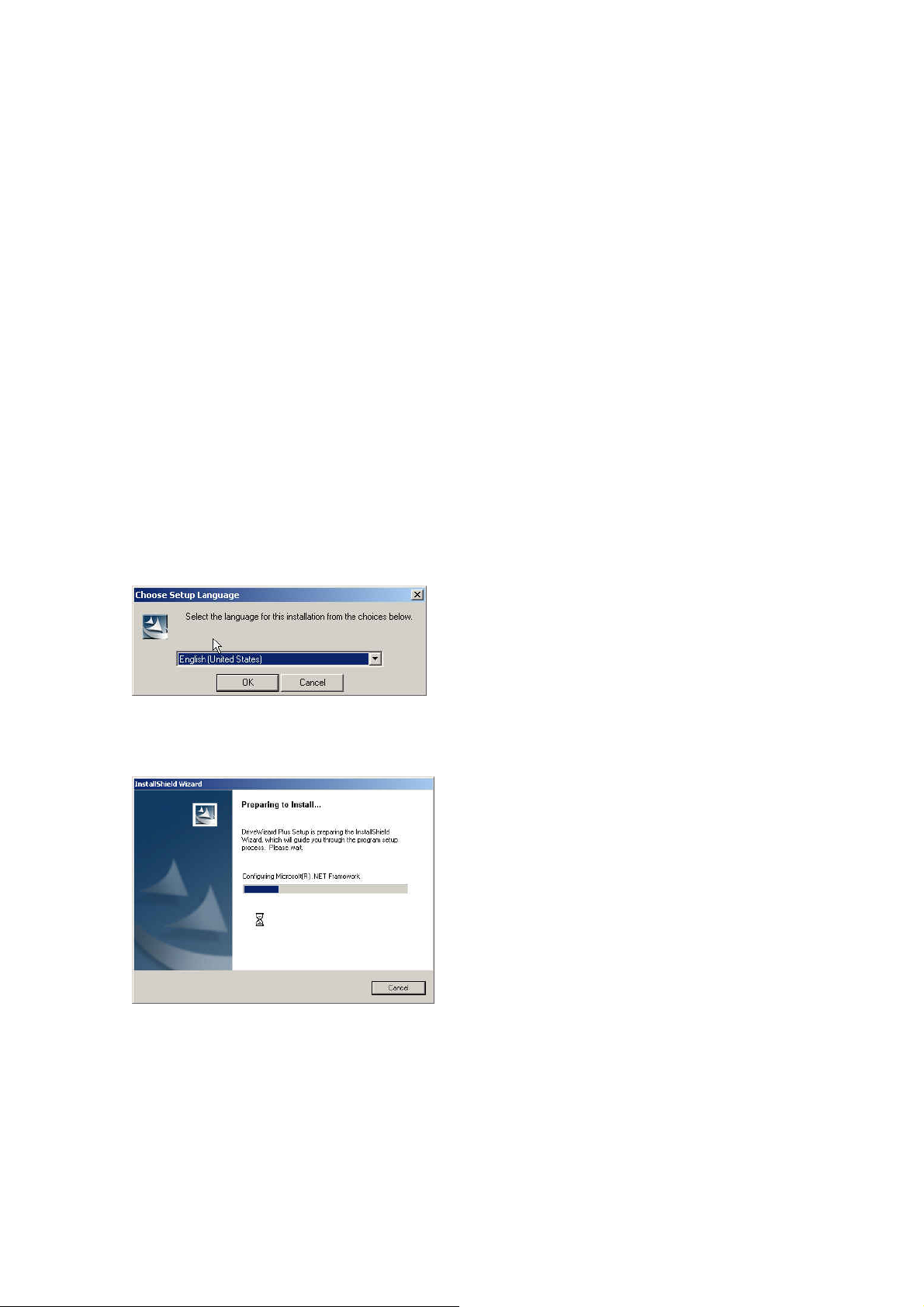
2) The Language selection dialog box will appear. Select the appropriate language (Japanese or
English).
®
Explorer, select the CD-ROM icon then double-click on “D: ¥SETUP.EXE”.
3) Click “OK” and DriveWizard Plus will prepare the InstallShield Wizard and then launch the
InstallShield Wizard for DriveWizard Plus. Click the button marked, “Next” to begin installation.
11
Page 12
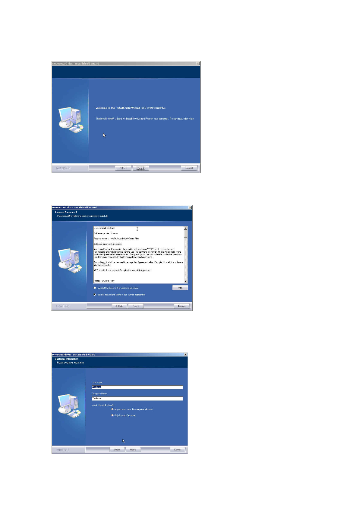
4) America software license agreement. You must accept the terms to proceed with the installation.
Click “Next” to continue.
5) Enter the user information into the required fields. The User Name and company information are
required for installation, registration, and use of the software. Click “Next” after the data has
been entered.
12
Page 13
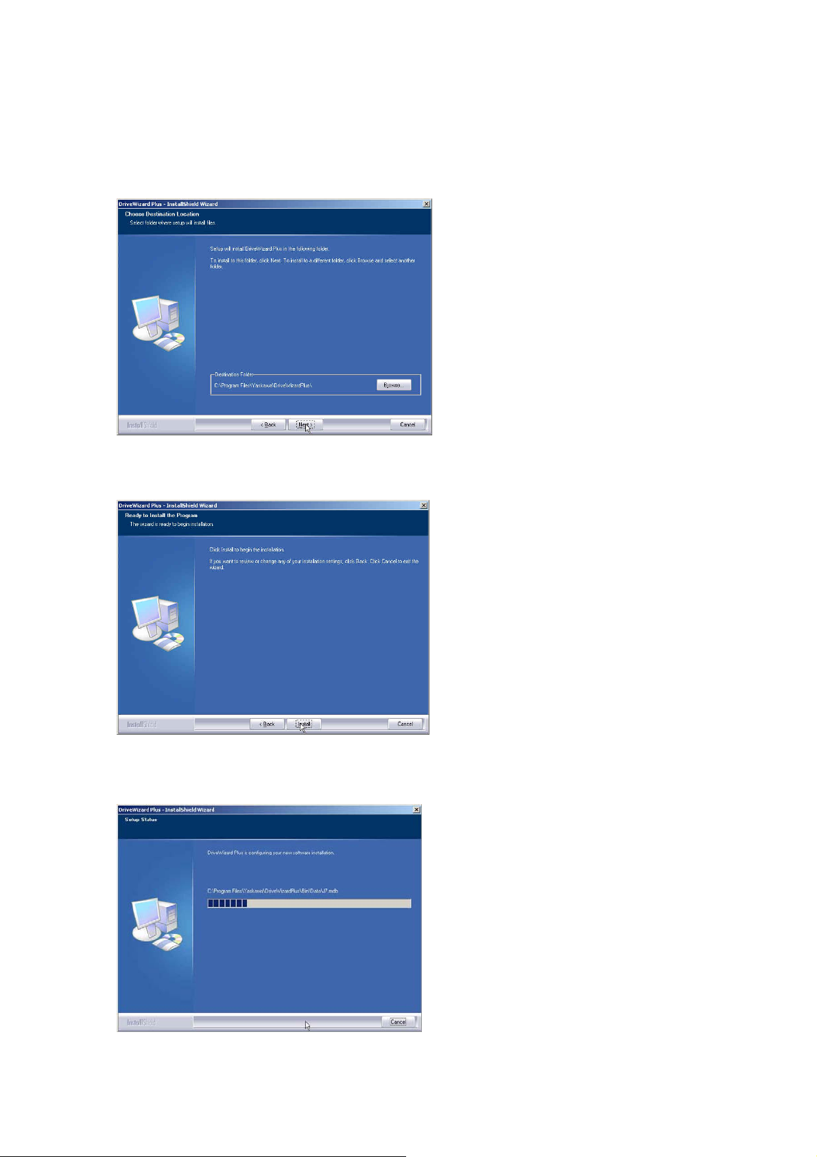
6) DriveWizard Plus asks for the software installation path. The default path will appear as:
C: Program Files¥Yaskawa¥DriveWizardPlus¥. Click “Next”.
7) Once DriveWizard Plus is ready to be installed, a message will appear to indicate that
installation preparations are complete. Click “Install” to install the software.
8) The required files will be installed and copied to the designated directory. A window will appear
to indicate the progress of installation.
13
Page 14
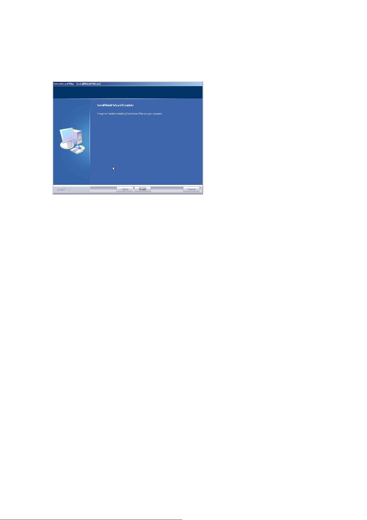
9) A message will appear to indicate that installation is complete. Click “Finish” to close the window.
NOTE: A message may appear indicating that the PC requires restart for proper DriveWizard
Plus installation. Follow the instructions and restart the computer.
14
Page 15
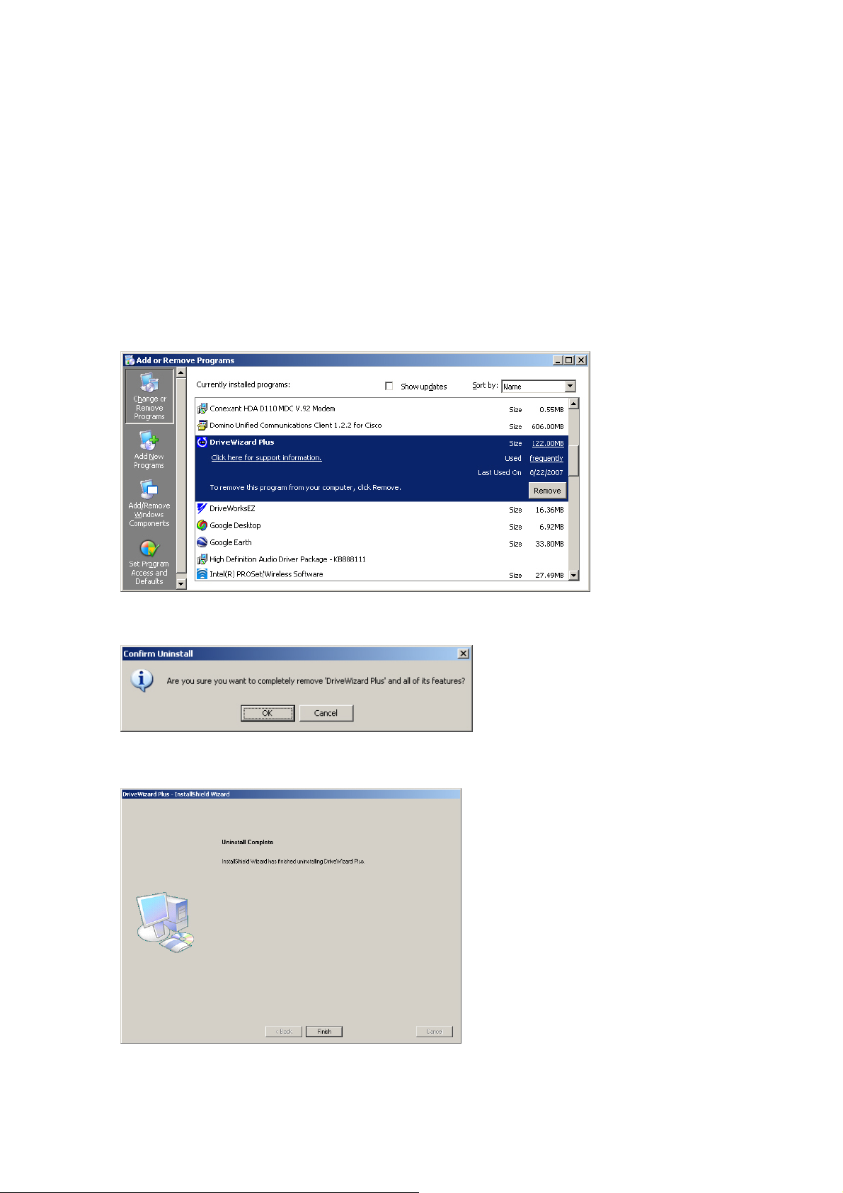
1.4 Uninstalling DriveWizard Plus
NOTE: Administrator privileges are required to uninstall DriveWizard Plus. Log in as the
administrator to uninstall DriveWizard Plus.
Follow the procedure below to uninstall DriveWizard Plus:
1. Open the Start menu in the Windows Task Bar.
2. Click on the “Settings” icon and open the Settings folder.
3. Click “Control Panel” and open the Control Panel folder.
4. Double-click on the “Add or Remove Programs” icon to open the following window:
5. Select DriveWizard Plus and click “Remove”. The following message will appear:
6. Click “OK” to execute the uninstall shield. When the program has been uninstalled, the following
message will appear:
7. Click “Finish”.
15
Page 16

2 Starting DriveWizard Plus
Follow the directions below to start using DriveWizard Plus:
2.1 Starting the Program
There are three ways to start a session of DriveWizard Plus:
・ from the Start menu
・ from a shortcut
・ by double-clicking on a Project file.
2.1.1 Starting from the Start Menu
Follow these instructions to open DriveWizard Plus from the Start menu:
1) Open the Start menu in the Windows task bar.
2) Go to the Programming menu and open the Programming folder.
3) Open the folder marked “YE_Applications”.
4) Select “DriveWizard Plus”.
2.1.2 Starting from a Shortcut
Double-click on the shortcut marked “DriveWizard Plus”.
2.1.3 Double-clicking on a Project File
DriveWizard Plus can be opened by double-clicking on a Project file.
1) Open up Windows Explorer
2) Double-click on a Project file icon.
NOTE: A Project file saved to the desktop can also be used to open a session of DriveWizard
Plus by double-clicking on that icon.
16
Page 17
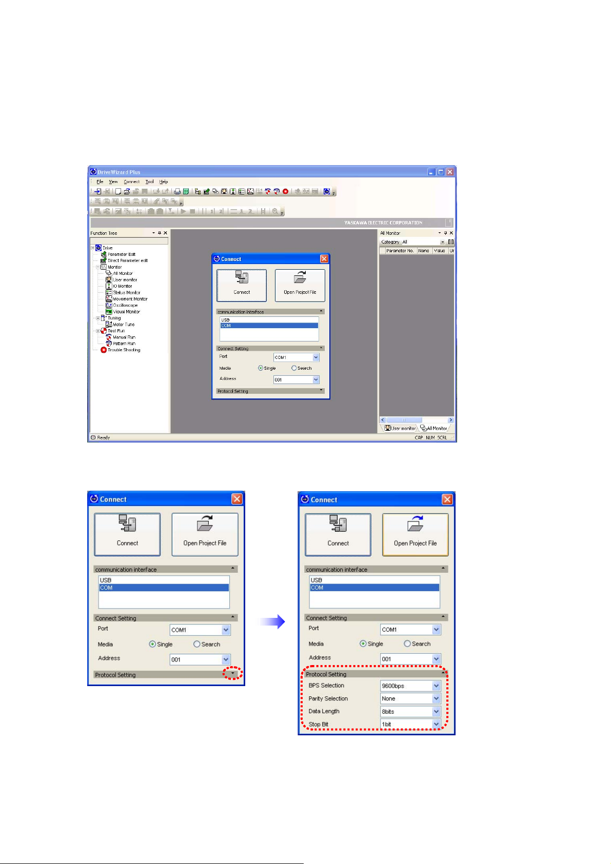
2.2 Connecting the Drive and PC via the Com Port
When DriveWizard Plus is first opened, the start up window shown below will appear on the
computer monitor.
The first window to appear asks if the user would like to connect to a drive or open up a Project file.
Connect: PC connects to the drive to edit parameters and perform test run.
Open Project File: Drive does not necessarily need to be connected to edit a project file.
17
Page 18

To connect a drive, DriveWizard Plus requires that certain data be entered for the “Connect Setting”
and “Protocol Setting”.
1) Specify the Connect Setting
Port
Selects the com port for drive connection. DriveWizard Plus will list the com ports available for
the PC being used. This display will vary by PC.
Media
Selects the media for setting the com address: Search or Single.
If you know the com address, enter it here. If not, select “Search” and DriveWizard Plus will
automatically search for the address.
Address
Sets the com address for drive parameter settings.
This setting will be grayed out when “Search” has been selected for the media.
2) Selecting the Protocol Setting
Sets the communication speed for drive and PC. As these settings vary by drive model, refer to
the instruction manual for proper settings.
BPS Selection
1200 bps, 2400 bps, 4800 bps, 9600 bps, 19200 bps, 38400 bps, 57600 bps, 76800 bps,
115200 bps
Parity Selection
None, Odd, Even
Data Length
7 bit / 8 bit
Stop bit
1 bit / 2 bit
3) Select “Connect”
DriveWizard Plus will attempt to connect to the drive. Once successful, data for that drive will
appear.
18
Page 19
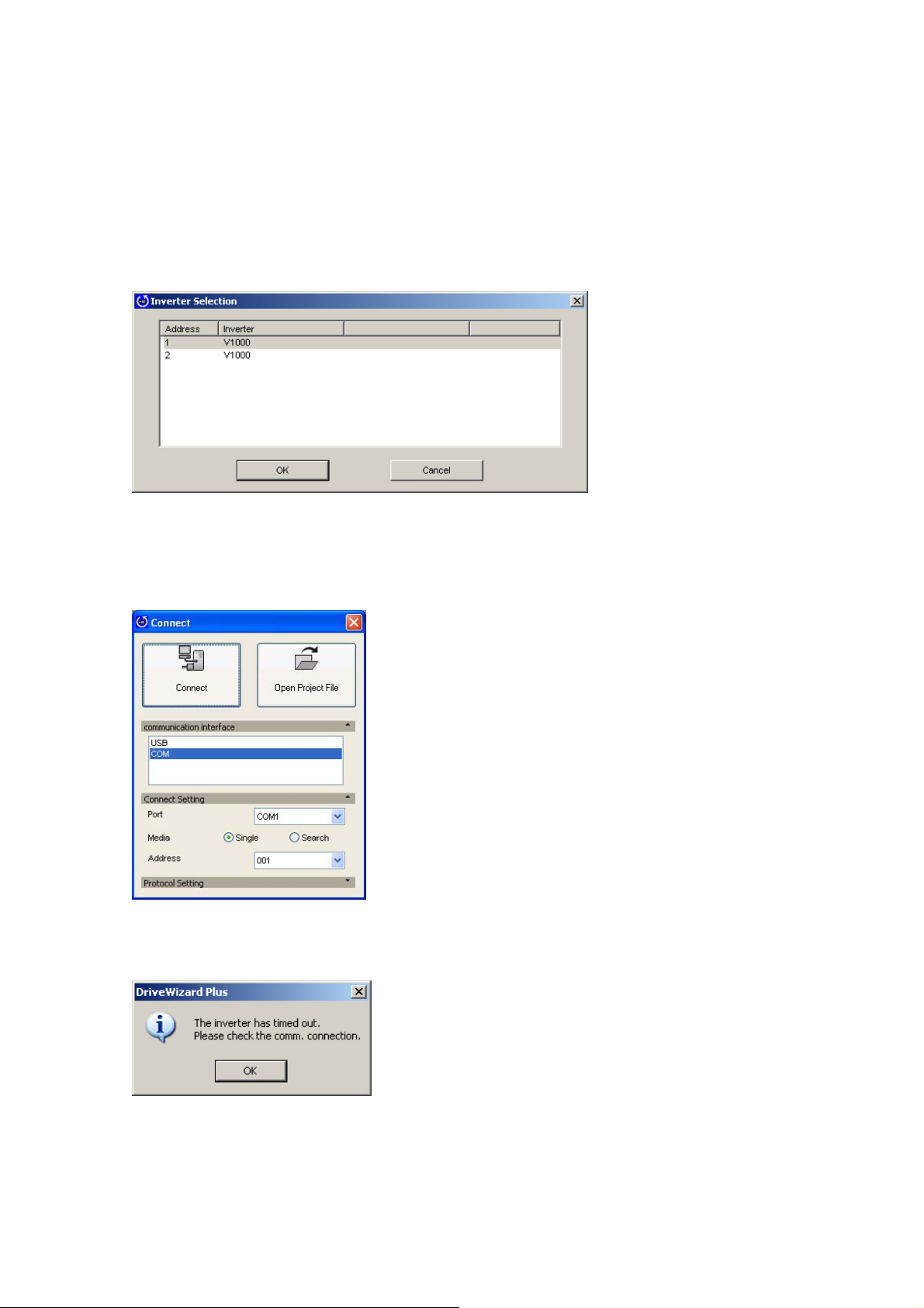
2.3 Connecting the Drive and PC
When the “Media” connection setting discussed in the previous section is set for search detection,
DriveWizard Plus will automatically search all serial ports for any connections.
If DriveWizard Plus detects that more than one drive is connected, the following window will appear,
showing the models and addresses of all drives that are connected.
NOTE: This window will only appear when more than one drive is connected.
Use the window above to select which drive the current session of DriveWizard Plus will focus on
and click “OK”. Clicking on “Cancel” will cause the following window to appear:
If DriveWizard Plus is unable to communicate with the drive, the window above will not appear and
the following message will be displayed instead:
Regardless of whether the drive is connected to the PC, this message may appear if DriveWizard
Plus is unable to properly communicate with the drive.
19
Page 20

If the drive selection screen fails to appear, check the items listed in the table below:
Check Comments
Is the power supply on?
Is there a loose connection
somewhere?
Is the correct com port selected? The com cable should be connected to the same port
Is the com address correct? RS-232C and USB
Is the RS-232C port enabled? Notebook PCs may not supply enough power to the RS-
Is the PC operating from a battery? PC batteries may not supply the type of power needed for
Is the wiring correct? Check for correct wiring using the instructions that came with
Is the com cable the proper length?
Make sure the com cable and the connector are properly
fastened to the correct ports.
specified in the Connect window.
Make sure the com address that is set and the one you are
trying to connect to are the same.
RS-422/ 485
Check the drive parameter settings for the com address and
make sure that the same com address has not been
selected twice, and that “0” is not selected.
232C port. Check the setting for the power supplied to the C
port. Refer to the PC user’s manual for information on setting
the power supply.
communications. Try switching to an AC power supply.
the com cable and the instruction manual for the drive.
・ Try shortening the length of the com cable
・ Use a twisted pair shielded line
・ Check the length of the com cable (RS-232C: 3 m max).
If DriveWizard Plus still has difficulty connecting to the drive after verifying all of the items
listed above, check the following:
・ Are the communication-related parameters in the drive set for use with DriveWizard Plus?
・ Remember that any changes to communication-related parameters in the drive require that power
be cycled in the drive for those new setting changes to take effect. Proper cycling of power means
that LED indicators on the operator must completely extinguish before the power supply back on.
20
Page 21
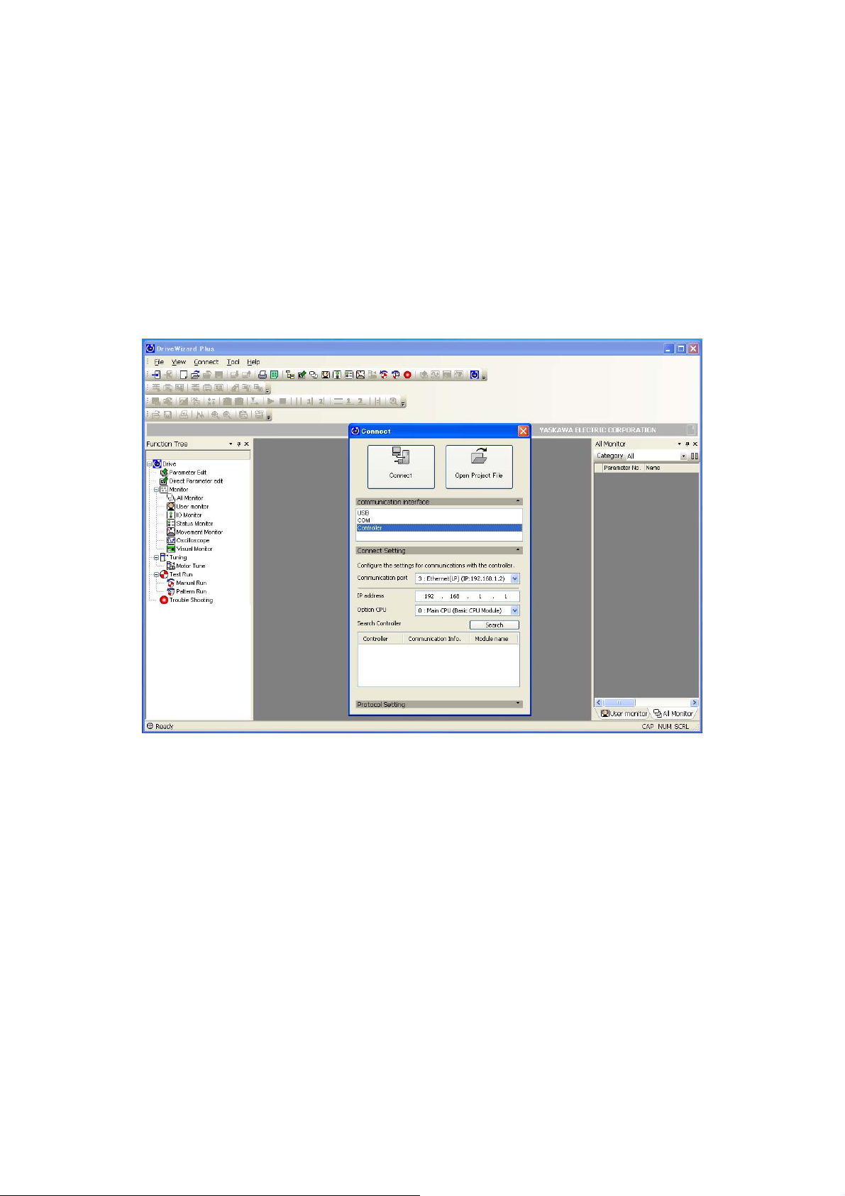
2.4 Connecting Via an Upper Controller
The procedure for connecting DriveWizard Plus to an upper controller using Ethernet/Ethernet (LP)
is different when using a different serial communications protocol.
When DriveWizard Plus is first started, the following window will appear.
If running a software version earlier than MPE720 Ver. 6, then the “Controller” option will not appear
on the drop-down menu as an interface option.
21
Page 22
2.4.1 Ethernet/Ethernet (LP) Connection
The IP address for the PC needs to be entered when connecting DriveWizard Plus to an upper
controller using Ethernet or Ethernet (LP).
The example below illustrates how to set the IP address in Windows XP.
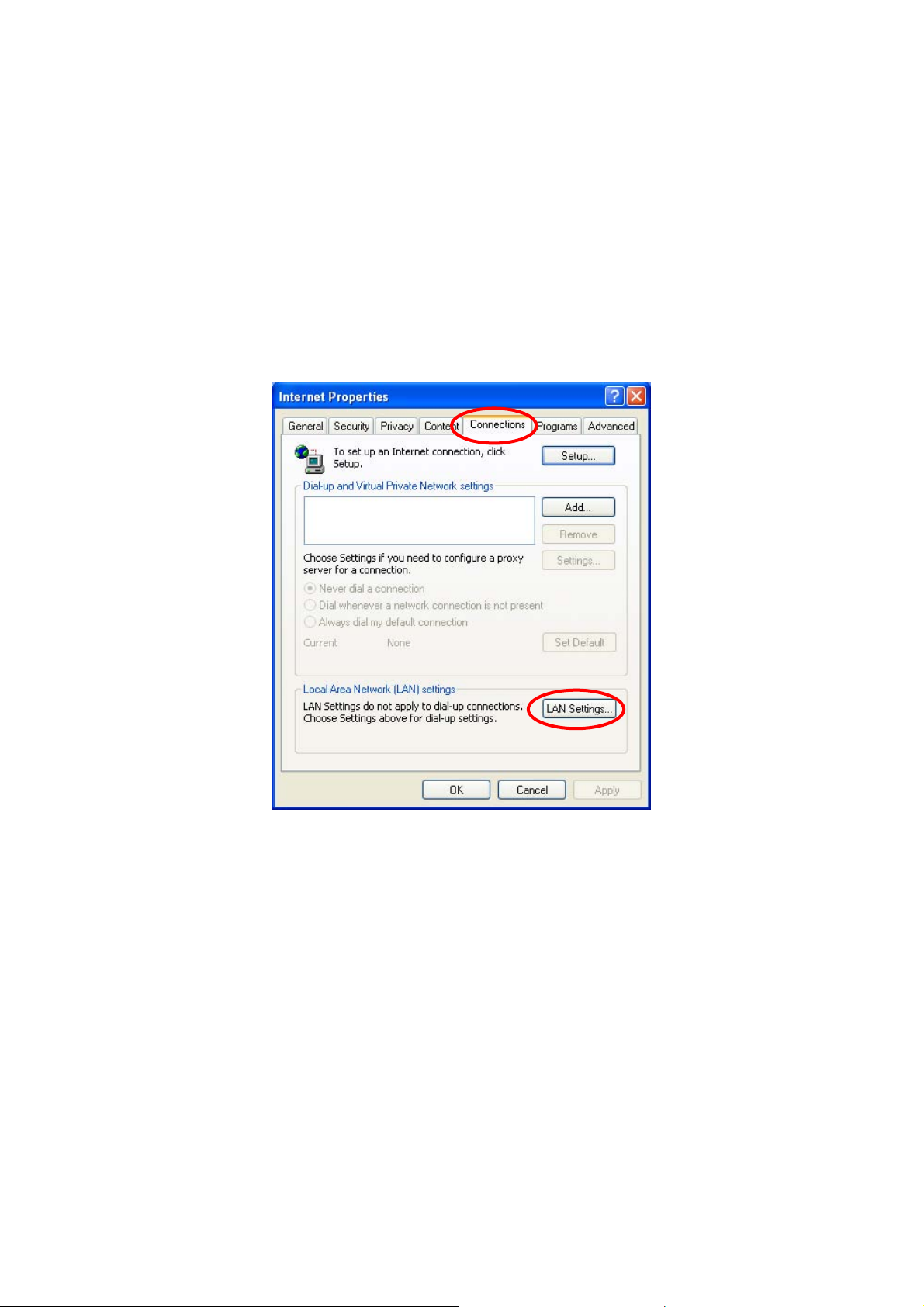
1) Go to the Start Menu Æ Settings Æ Control Panel, and double click on the “Internet Options”
icon.
The following window will appear:
22
Page 23
2) Click on the “Connections” tab, then click the button marked, “LAN settings”.
The following window will appear:
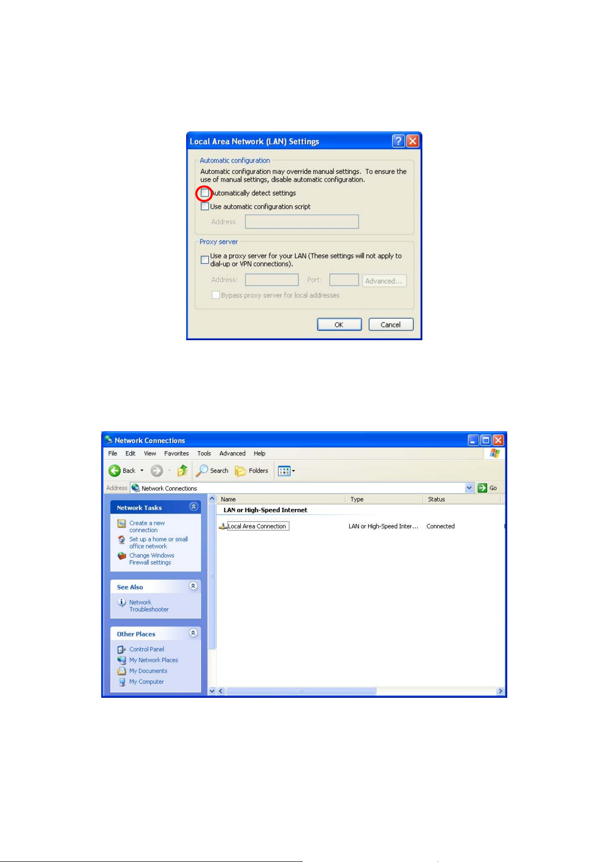
3) Make sure the check box marked, “Automatically detect settings” is unchecked, and click “OK”.
4) Go to the Start Menu Æ Settings Æ Control Panel, and double click on the “Network
Connections” icon.
The following window will appear:
23
Page 24
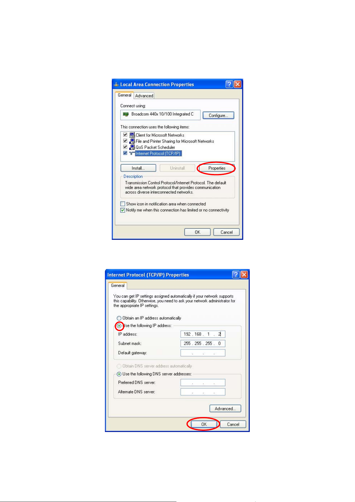
5) Select “Local Area Connection”, then in the Network Task box, click on “Change settings of this
connection”. The following window will appear:
6) Select “Internet Protocol (TCP/IP)” and click “Properties”.
The following window will appear:
24
Page 25
7) Click “Use the following IP address”. Enter the “255. 255. 255. 0” for the subnet mask and an
arbitrary IP address for the IP address. Click “OK” to close the window.
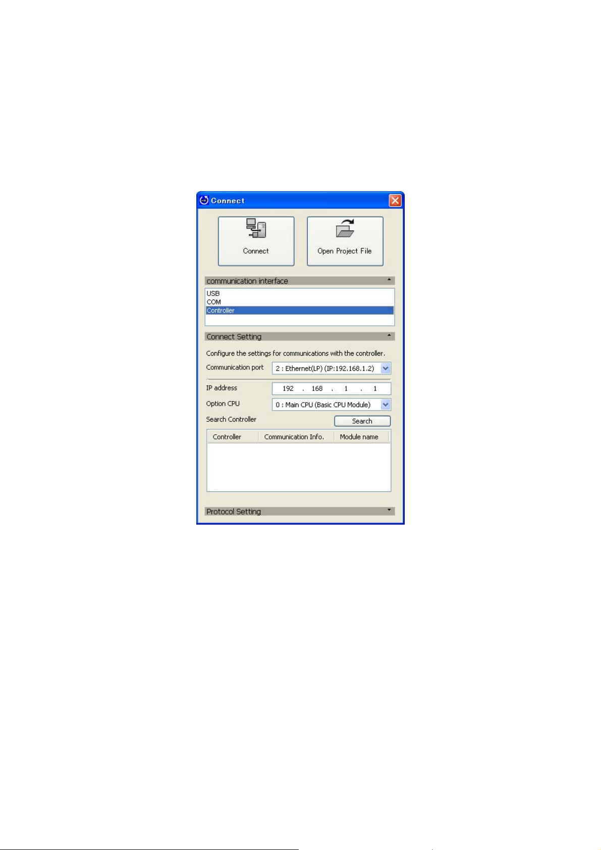
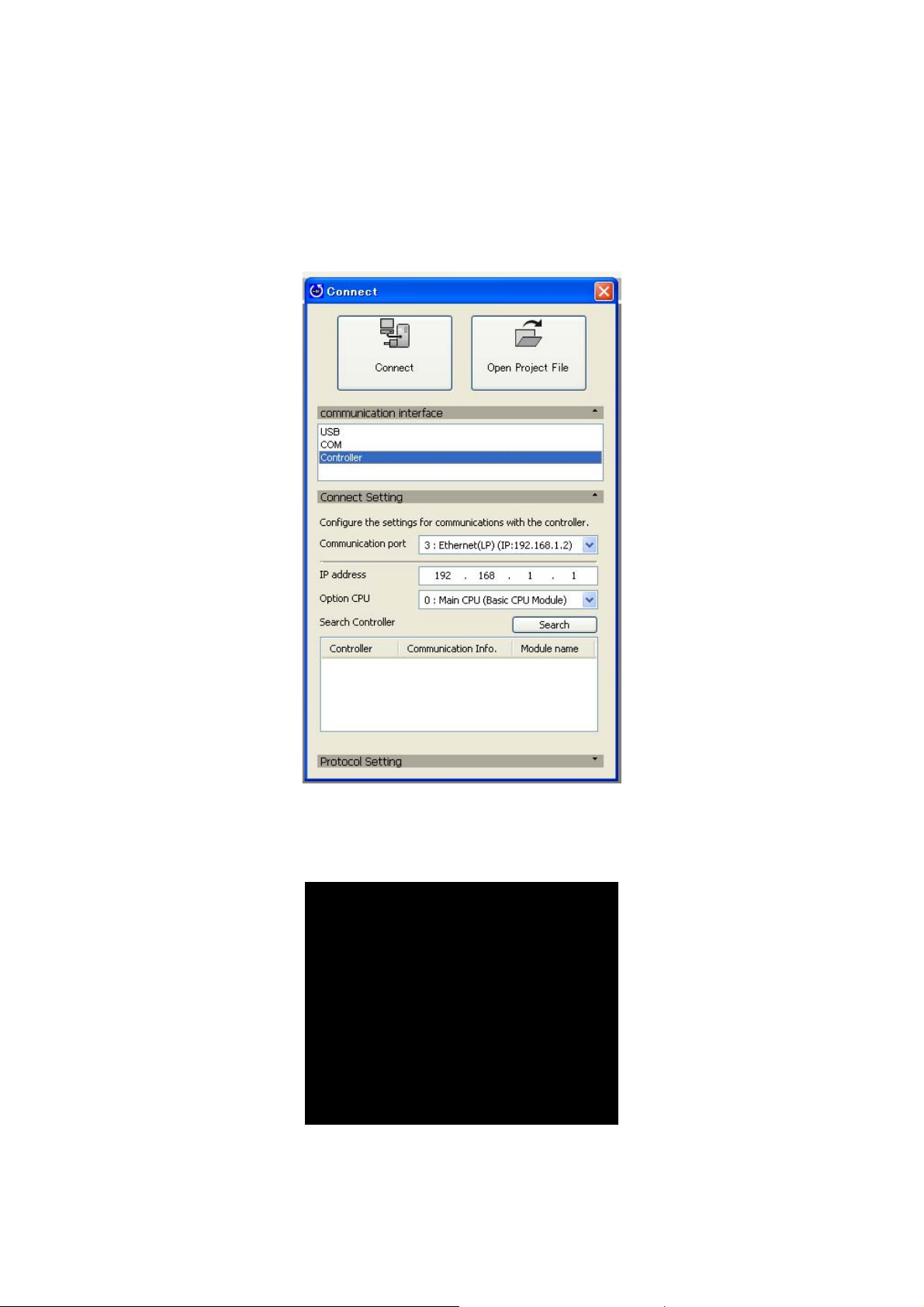
8) Next, open DriveWizard Plus and click “Connect”. Select “Controller” from the communication
interface option.
The following window will appear:
Drive Connect Window
25
Page 26

9) Select the appropriate communication port and click “Connect”.
When Using Ethernet
Select “Ethernet” for the communication port.
Drive Connect Window
When Using Ethernet (LP)
Select “Ethernet (LP)” for the communication port.
Drive Connect Window
When using Ethernet (LP), verify the IP address for possible controller devices as described below.
1) Click “Search”.
The controller names, IP addresses, ports, and module names should appear in the window.
2) Make sure that the IP address of the communication port that has been selected matches
the information listed in the search results window, then click “Connect”.
NOTE: The controller search window appears only when Ethernet (LP) has been selected.
26
Page 27
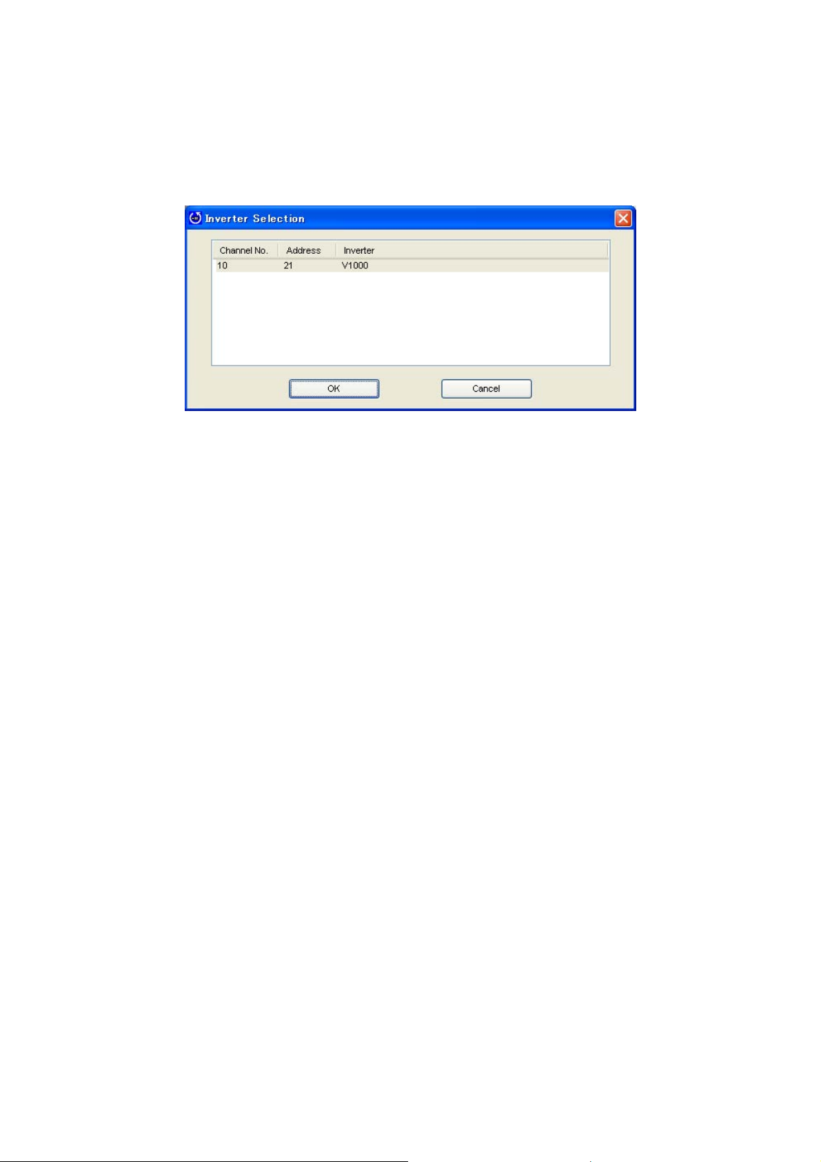
DriveWizard Plus searches for possible connections via the MECHATROLINK communication
cable. Search results appear in the Inverter Selection window.
Inverter Selection Window
Channel No.
The channel for each SVB module is displayed as a hexadecimal number.
Address
The node address for each MECHATROLINK node is displayed as a hexadecimal number.
Inverter
Displays the drive model.
10) Select the drive to connect to and click “OK”.
DriveWizard Plus will begin connecting to the drive. The drive is online once connection is
complete.
27
Page 28

An error message may appear regardless if DriveWizard Plus is connected to a drive or not. Refer
to the check list in the table below if an error occurs.
Check Comments
Is the power on?
Is the connector loose? Make sure the connector on the communication
cable is securely fastened.
Has the correct communication port been
selected?
Is the IP address setting correct? Is should match the IP address for the controller.
Is the PC running on battery? Serial communication problems can occur when
Is wiring correct? For wiring instructions, refer to the instruction manual
Is the number of node restarts set to 0? The number of node restarts should be set greater
Regardless of how the drives are
configured, is the number of drives properly
displayed?
Is the wiring for MECHATROLINK-II
correct?
Is there a problem receiving
MECHATROLINK-II data due to noise?
Make sure that the selected port is the same port
that is connected to the communication cables.
running a PC from the battery. Use an AC power
supply.
that came with the serial communication cable and to
the instruction manual for the drive.
than 1.
Increase the number of node addresses.
If it is not possible to increase the number of
addresses, take the following steps:
• Delete the configuration set for the drive axes.
Note that this will clear parameter values that may
have been set for axis configuration.
•Set up the drives again for DriveWizard Plus.
Check the MECHATROLINK-II wiring.
• Wire the MECHATROLINK-II communication cable
correctly.
• Connect a terminator correctly.
• Take steps to reduce noise.
This might include changing the MEHCATROLINK-II
communication cable or FG wiring, or using a ferrite
core for the communication cable.
NOTE: If DriveWizard Plus still does not properly display the drives that are connected after
going through the check list above, then try the following:
・ Make sure the drive’s parameters for serial communications and the SVB module setting
match.
・ If any changes have been made to communication-related parameters, then power to the
drive needs to be cycled to enable those changes. Note that the LED display on the drive
needs to go out completely when shutting off the power.
28
Page 29
2.4.2 Other Communication Protocols Besides Ethernet/Ethernet (LP)
1) First, open DriveWizard Plus and click “Connect”. Select “Controller” from the communication
interface option.
The following window will appear:
Drive Connect Window
2) Specify the port for the controller and click “Connect”.
For the communication port, select MP2100/MP2500.
Drive Connect Window
29
Page 30
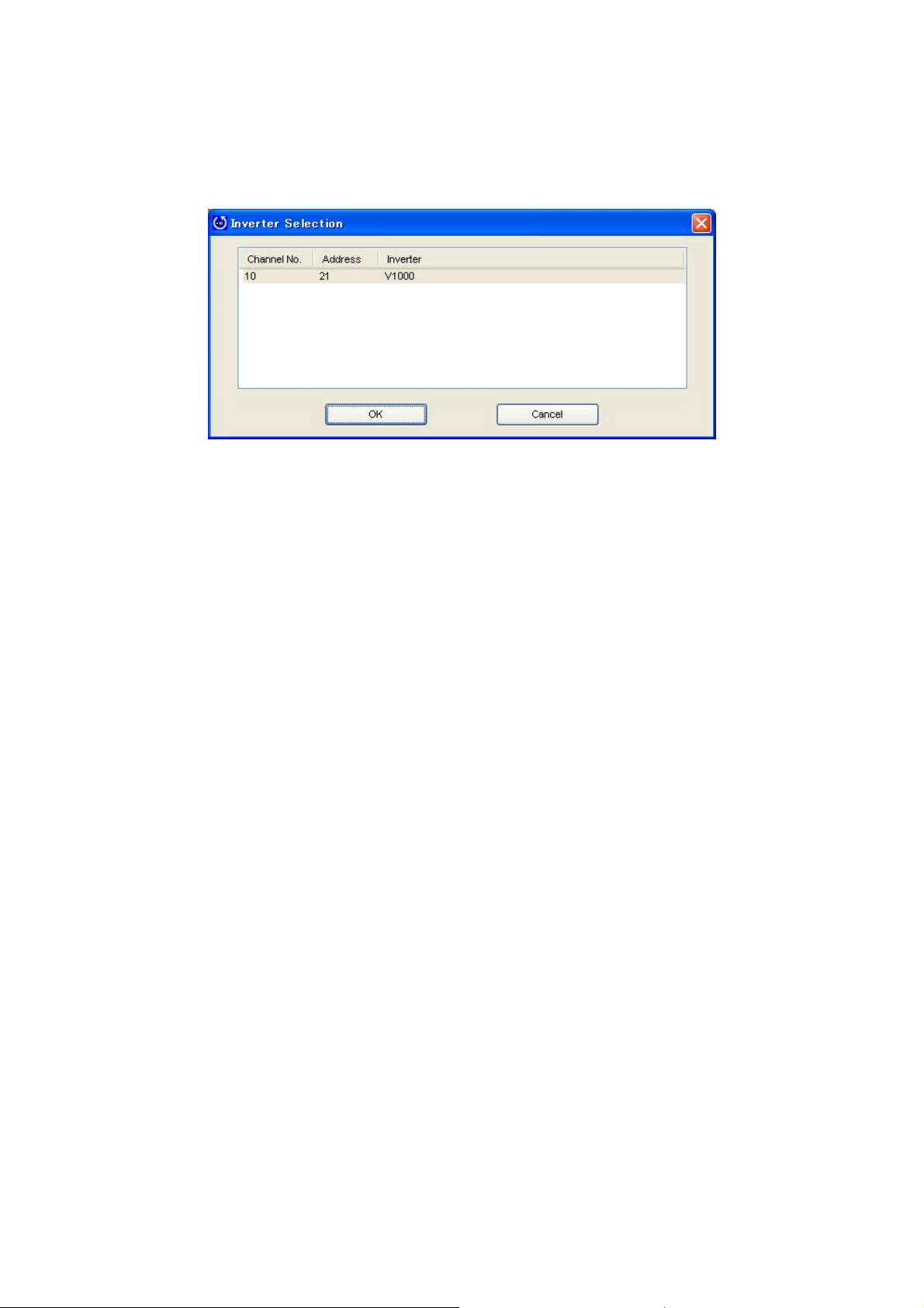
DriveWizard Plus searches for possible connections via the MECHATROLINK communication
cable. Search results appear in the Inverter Selection window.
Inverter Selection Window
Channel No.
The channel for each SVB module is displayed as a hexadecimal number.
Address
The node address for each MECHATROLINK node is displayed as a hexadecimal number.
Inverter
Displays the drive model.
30
Page 31

3) Select the drive to connect to and click “OK”.
DriveWizard Plus will begin connecting to the drive. The drive is online once connection is
complete.
An error message may appear regardless if DriveWizard Plus is connected to a drive or not.
Refer to the check list in the table below if an error occurs.
Check Comments
Is the power on?
Has the correct communication port been
selected?
Is the CPU number correct? Make sure the CPU number connected to the
Is the number of node restarts set to 0? The number of node restarts should be set greater
Regardless of how the drives are
configured, is the number of drives properly
displayed?
Is the wiring for MECHATROLINK-II
correct?
Is there a problem receiving
MECHATROLINK-II data due to noise?
controller is set correctly.
than 1.
Increase the number of node addresses.
If it is not possible to increase the number of
addresses, take the following steps:
• Delete the configuration set for the drive axes.
Note that this will clear parameter values that may
have been set for axis configuration.
•Set up the drives again for DriveWizard Plus.
Check the MECHATROLINK-II wiring.
• Wire the MECHATROLINK-II communication cable
correctly.
• Connect a terminator correctly.
• Take steps to reduce noise.
This might include changing the MEHCATROLINK-II
communication cable or FG wiring, or using a ferrite
core for the communication cable correctly.
NOTE: If DriveWizard Plus still does not properly display the drives that are connected after
going through the check list above, then try the following:
・ Make sure the drive’s parameters for serial communications and the SVB module setting
match.
・ If any changes have been made to communication-related parameters, then power to the
drive needs to be cycled to enable those changes. Note that the LED display on the drive
needs to go out completely when shutting off the power.
31
Page 32

2.5 Managing Project Files
Data handled by DriveWizard Plus is organized into a Project.
Users can assign names to a Project.
A Project stores all connection data, drive functions, and data that have been edited into a single file
to facilitate data tracking and portability.
The flowcharts in the next section outline starting DriveWizard Plus, creating a Project, and quitting
the program.
32
Page 33

2.5.1 Starting DriveWizard Plus
① Starting DriveWizard Plus
⑥ Active DriveWizard Plus application
B
② Connection status display
NG
Is DriveWizard
Plus open?
NO
Successfully
connected?
YES
*4
YES
*Returns to the screen for opening
a previously saved Project.
④ Select a Project File.
Open an existing Project*2 No Project specified*3 Open a New Project*1
NO
Is the drive
connected?
YES
*4
Drive connection
If there is no communication data set, DriveWizard
Plus will use default com settings.
A
⑤ Start DriveWizard Plus
Drive model
data invalid
NO
Successfully
connected?
*4
NO
Communications error
A
YES
A
*1
New Project :
DriveWizard Plus creates a new Project file and automatically assigns default values to all parameters.
The Project must be given a name when it is saved.
*2
Pre-existing Project :
The user selects a Project that was saved earlier.
*3 No Project No Project file is opened. No data will be displayed and no parameters can be edited.
・No child windows (such as the Parameter Edit window, etc.) will be displayed.
・If any docking windows are open, they will not display any data or drive model information.
Software functions will become enabled once a Project is opened or once DriveWizard Plus connects to the drive.
*4 Once a Project has been opened, double check that the drive model information is correct.
33
Page 34

C
2.5.2 Double-clicking on a Project File from Windows Explorer
① Double click on a Project File.
Is DriveWorks Plus
already running?
Does the Project File have a
NO
YES
NO (New Project)
name?
Assign a name
B
YES
Does the same Project already exist?
NO
B
A
34
Page 35

Has the file been edited
C
since it was last saved?
NO
③Enter the name
of the Project File
② Save verification
YES
B
NO (New Project)
Has the Project been named?
YES
Save the Project
Close the Project
Still connected?
B
Disconnect drive
④Close all windows (except tree)
NO
YES
A
35
Page 36

2.5.3 Opening a Project File
① Opening a Project File
A
When a Project is already open, the
“Project Open” selection on the menu is
disabled so that only “New Project” can be
selected.
36
Page 37

2.5.4 Closing a Project File
① Closing a Project File
③ Specify the Project file
Has the file been edited
NO
since it was last saved?
②Safe verification
YES
B
NO (New Project)
Project Name
YES
Saves Project.
Closes the Project File
Already connected?
B
YES
DriveWizard Plus disconnects
the drive and PC.
④ DriveWizard Plus closes all windows (except the tree window)
NO
37
Page 38

2.5.5 Connecting the Drive to the PC
① Connecting the Drive
② Connection Display
Drive connected?
YES
NO
Disconnects the drive
NG
③ If a Project is already open, DriveWizard Plus will connect with the file open.
Drive connected?
OK
38
Page 39

?
2.5.6 Disconnecting the Drive
① Disconnecting the drive
Already
connected
YES
NO
Disconnect the drive
② If a Project File is open, DriveWizard Plus will disconnect the drive and leave the file open.
39
Page 40

2.5.7 Saving a Project File
① Saving a Project File
Does the Project File have a name?
Save Project.
③ Project file remains open
NO (New Project)
② Specify a Project name
YES
40
Page 41

2.5.8 Save Project File As
① Saving a Project
② Enter the Project file name
Saves the Project file
③ Returns to the open Project
41
Page 42

2.5.9 Quitting the Application
See “2.4.4 Closing a Project”.
2.5.10 Managing Project Files with the Menu
DriveWizard Plus
application closes.
Project already open Project not yet opened Situation
Menu
2.4.2 Creating a New Project
2.4.3 Opening a Project File
2.4.4 Closing a Project
2.4.5 Connecting to the Drive
2.4.6 Disconnecting the Drive
2.4.7 Saving a Project
2.4.8 Saving a Project As
2.4.9 Quit
○: Selection possible,×: Selection not possible.
Drive Connected Not Connected Drive Connected Not Connected
× × ○ ○
× × ○ ○
○ ○ × ×
× ○ × ○
○ × ○ ×
○ ○ × ×
○ ○ ○ ×
○ ○ ○ ○
42
Page 43

3 DriveWizard Plus Main Screen
The main screen when DriveWizard Plus is first opened appears below.
43
Page 44

3.1 Screen Construction
g
T
T
r
r
r
The illustration below indicates the various windows, tabs, and toolbars that appear in the main screen.
Title Bar
Main Menu
Toolbar
Document Window
itle
window)
Tree Window
(dockin
Status Bar Message
Child Window Tab
Docking Window
itle
Caption Bar Message
Child Window
Window Size Selecto
Child Window
Docking Window (floating window)
Docking Window
Window Size Selecto
Window
Docking
(floating window)
Docking Window Tab
Docking Window
Window Size Selecto
Status Bar Indicator
44
Page 45

3.1.1 Title Bar
The title bar in DriveWizard Plus shows all active child windows.
When no child windows are displayed
When the Parameter Display Screen is open as a child window
When the Oscilloscope Display is open as a child window
The title bar appears below:
①
NO. DESCRIPTION
①
Displays the DriveWizard Plus icon.
②
Displays the name of the application (DriveWizard Plus) and information on the child window.
③
Minimizes or maximizes the size of the window.
②
③
45
Page 46

3.1.2 Main Menu
Options available in the Main Menu in DriveWizard Plus appear below.
(1) Menu
File (F)
Edit (E)*1
View (V)
Connection (C)
Monitor (M)*1
Tools (T)
Help (H)
*1: For a more detailed description of Menu items, see the description for each function that follows.
(2) File Menu
MENU DESCRIPTION
For reading and writing data from a Project, displaying drive information, as well as
importing and exporting files.
This menu becomes available when using the Parameter Edit and Oscilloscope windows.
*This menu is not available when not using a corresponding child window.
Determines which function windows are displayed or not displayed.
For connecting and disconnecting the drive.
For starting and stopping to trace drive performance with the Oscilloscope.
*This menu is available only when using the Oscilloscope function.
*1
Opens the tools related to the current task.
Displays Help information, including the manual, drive data, and software version data.
SUBMENU DESCRIPTION
Create New Project (N)… Creates a new Project.
Open Project (O)… Open a Project that was saved earlier.
Save Project (S) Saves the current Project.
Save Project As (A) … Saves the current Project under a new or different name
Close Project (L) Closes the current Project.
Closing a Project will disconnect the drive if connected.
Drive Data (T)… Displays data from the drive when the drive is connected.
Import (I)… Imports items as selected in the active window.
Imports files created in an older version of DriveWizard.
Export (E)… Exports items selected in the active window.
Print Settings (P)… Changes settings for print out.
Environment setup (V)… For various program environment settings (how data is saved, use of filters, etc.).
(Project History) Displays a list of the five most recently opened Projects.
Quit (X) Close the current session of DriveWizard Plus
46
Page 47

(3) Display Menu
SUBMENU SELECTION DESCRIPTION
Function Tree
Direct Parameter Edit
All Monitors
User Monitor
I/O Monitor
Status Monitor
Operation Monitor
Manual Operation
Pattern Operation
Troubleshooting
Results List
Drive Replacement
Conversion Results
Motor Parameter Auto-Tuning
Visual Monitor
Parameter Edit
Oscilloscope
Toolbar (T)
Standard (S)
Parameter Edit (E)
Oscilloscope (O)
Customize (C
Language*2
English
J
apanese
)…
○
○
○
○
○
○
○
○
○
○
○
○
○
-
-
-
-
-
○
○
○
-
-
-
-
Displays the Function Tree.
Opens the Direct Parameter Edit window.
Displays all monitors.
Displays user monitors only.
Displays the input and output monitors.
Displays the Status Monitor.
Displays the Operation Monitor.
Displays the window for performing Manual Run.
*This function cannot be used when connected to an upper controller.
Displays the window for performing Pattern Run.
*This function cannot be used when connected to an upper controller.
Shows the Troubleshooting window.
Displays the results after comparing parameters.
Displays the function for replacing the drive with a different model.
Displays the results after performing a Parameter Conversion.
Begins the Auto-Tuning process.
Displays the Visual Monitors.
*Exclusive functions for the V1000 and J1000 series
Opens the window for editing parameters.
Displays the Oscilloscope window.
Displays or hides the toolbar.
Displays or hides the standard toolbar.
Displays or hides the toolbar for editing parameters.
Displays or hides the Oscilloscope toolbar.
Opens the window for customizing the menu and toolbar.
For selecting which language to display.
Displays English only.
English is not displayed when English has been selected.
Displays Japanese language settings.
Japanese is not displayed when Japanese has been selected.
*2: Changing the Language Selection requires restarting DriveWizard Plus. Available languages
differ dependent on software versions.
47
Page 48

(4) Connect Menu
SUBMENU DESCRIPTION
Connect Inverter (C)… Connects the drive to the PC.
Disconnect Inverter Disconnects the drive that is currently connected.
(5) Tool Menu
SUBMENU DESCRIPTION
DriveWorksEZ (E) Opens DriveWorksEZ.
Drive Replacement (R) For updating or replacing a drive with a different model.
(6) Help Menu
SUBMENU DESCRIPTION
DriveWizard Plus Manual (M) … Opens the instruction manual for DriveWizard Plus.
Inverter Help (I) … Offers Help information on various drives.
Version Data (A)… Displays the version of DriveWizard Plus currently installed.
*If already connected, this selection will read, “Reconnect (R)”.
*This selection is only available when a drive is connected.
*Requires that DriveWorksEZ be installed separately.
(7) Edit Menu (Parameter Edit)
Submenu Description
Write selected parameters (S) Writes the value for the selected parameters to the drive.
Write group (G)… Writes the setting values for the entire group of parameters selected to the drive.
Select All Parameters (A) Writes the setting values for all parameters to the drive.
Read selected parameters (E) Read the parameters selected from the drive that is connected.
Read Group (R)… Reads the specified group of parameters from the drive.
Read All Parameters (L) Reads all parameters from the drive.
Drive initialized (I)… Initializes the drive.
Drive Compare (C) Compares parameters settings in the current Project with parameter settings stored in
File Compare (F)… Compares the parameter settings in the current Project with another Project or
Comment Edit (D) Opens the Comment Edit window.
the drive that is connected. This option is disabled when no drive is connected.
parameter file.
48
Page 49

3.1.3 Toolbars
A list of toolbars in DriveWizard Plus appears below.
Standard Toolbar
ICON FUNCTION
Connects to the drive.
Disconnects the drive.
Creates a new Project.
Opens an existing Project.
Closes the Project currently open.
Imports the data selected.
Exports the data selected.
Prints the current document.
Opens the Environment setup window.
Displays the Direct Edit window.
Displays the All Monitor function.
Displays the User monitor.
Displays the I/O Monitor function window.
Shows the Status Monitor.
Shows the Operation Monitor.
Executes Auto-Tuning.
Shows the Manual Run window.
Shows the Pattern Run window.
Displays information for Trouble-Shooting.
Displays the Parameter Edit window.
Displays the Oscilloscope.
Shows the Visual Monitor window.
Shows software version information.
Saves the Project.
Displays the Function Tree window.
49
Page 50

Parameter Edit Toolbar
ICON FUNCTION
Saves the selected parameter to the drive.
Saves an entire group of parameters to the drive.
Saves all parameters to the drive.
Reads the selected parameter.
Reads a group of parameters from the drive.
Reads all parameters from the drive.
Initializes the drive.
Compares settings in the drive.
Compares a file.
Opens the Comment Edit window.
Oscilloscope Toolbar
ICON FUNCTION
Saves the data that was collected.
Reads data that was collected.
Switches the background color and the waveform color.
Copies an image of the waveform.
Displays the calculations toolbar.
Takes a snapshot of the data selected.
Erases the snapshot data.
Displays the Trigger Conditions Setting dialog box.
Starts monitoring drive performance.
Stops monitoring drive performance.
Switches to the vertical cursor display.
Sets the V1 vertical cursor.
Sets the V2 vertical cursor.
Switches to the horizontal cursor display.
Sets the H1 horizontal cursor.
Sets the H2 horizontal cursor.
Moves the cursor.
Enlarges the waveform display.
50
Page 51

3.1.4 Caption Bar
The Caption bar shows the connection status with the drive.
When the drive and PC are not connected:
The following displays appear when the drive and PC are connected:
When properly connected, the Caption bar will display:
The drive is stopped:
During run:
The following displays indicate that there is a problem with the connection:
A streaming arrow indicates the connection status
A streaming arrow indicates the connection status
51
Page 52

j
3.1.5 Tree Window
All functions in DriveWizard Plus can be executed from the Function Tree window.
Displays information regarding the Project that is currently
open.
Drive data also appears when connected to the drive. If
no drive is connected, then the display will show data for
the drive the Pro
Displays the Function menu.
Functions are listed by category. By double clicking on an
item in the tree, a function window that corresponds to
that menu item will appear.
If a window for that function is not already open, a new
window will appear.
ect has been assigned to.
52
Page 53

Right-clicking on the nodes in the display screen will cause a context menu to appear.
Most menus read “Open (O
)” while others offer more functions.
No. Item Menu Operation Description
1 Root
Inverter information (T)… Displays data read from the drive.
Connect Inverter (C) Connects the drive and PC.
Disconnect Inverter (D
) Disconnects the drive from the PC.
Open (O) Opens the Parameter Edit window. 2 Parameter Edit
User Parameter (U
)... Opens the User Parameter setting window.
3 Direct Parameter Edit Open (O) Opens the Direct Parameter Edit window.
4 Monitor
5 All Monitors Open (O) Opens a window displaying all monitors.
User Monitor
6
- -
Open (O) Opens the User Monitor window.
Monitor item setting (M)... Opens the Monitor Item Setting Dialog
7 I/O Monitor Open (O) Opens the I/O Monitor window.
8 Status Monitor Open (O) Opens the Status Monitor window.
Movement Monitor
9
Open (O) Opens the Movement Monitor window.
Monitor item setting (M
)... Opens the Monitor Item Setting toolbar.
10 Oscilloscope Open (O) Opens the Oscilloscope screen.
11
12 Tuning
13 Motor Parameter
Visual Monitor Open (O) Opens the Visual Monitor screen.
- -
Open (O)) Opens the Motor Parameter Auto-Tuning screen.
Auto-Tuning
14 Trial Run
15 Manual Operation Open (O) Opens the Manual Run window.
16
Pattern Operation Open (O) Opens the Pattern Run window.
- -
17 Troubleshooting Open (O) Opens the Troubleshooting window.
53
Page 54

3.1.6 Child Window
The Parameter Edit screen, Oscilloscope, and Visual Monitor functions are displayed in child windows as
shown below.
Parameter Edit Window Oscilloscope Window
Visual Monitor Window
You can switch between displays by clicking on the tabs in the child window, including the Parameter
Display window, Oscilloscope, and Visual Monitor functions.
You can also change the screen layout so that the various windows are stacked horizontally or vertically.
54
Page 55

Example of screen layout:
55
Page 56

3.1.7 Docking Windows and Floating Windows
Monitor, Manual Run, Pattern Run, and Troubleshooting functions are displayed as docking windows.
These windows can be separated from one another to become floating windows.
When windows are docked together, other windows may be hidden with the auto-hide function.
The Auto-Hide
button hides
the window.
A tooltip indicating the name of the tab will appear
as the mouse pointer moves over each tab.
*Only the active window is displayed. Other
windows are hidden automatically.
56
Page 57

3.1.8 Status Bar
The Status Bar shows the progress of the command being executed.
①
When reading parameters from the drive:
①
No. Description
①
Icon appears to indicate the status of DriveWizard Plus.
②
Text to indicate the current status of DriveWizard Plus appears here.
③
Progress bar is displayed while the command is executed.
④
Indicates the keyboard status of the Caps Lock, Num Lock, and Scroll Lock keys.
②
②
③
③
④
④
57
Page 58

4 Editing Drive Data
4.1 Drive Model Data Display
You can display information on the connected drive by selecting ”File (F)” in the Main Menu Æ “Inverter
information (T
information (T
NOTE: No data is displayed if the drive is not online.
)…”, or by right-clicking on the Function Tree “Drive (number)” and selecting “Inverter
)…” in the menu.
58
Page 59

4.2 Parameter Edit
There are two ways to edit parameters:
・ Parameter Edit window
・ Direct Edit window
4.2.1 Parameter Edit Window
The Parameter Edit window lets you change and edit parameter settings.
4.2.1.1 Online Parameter Edit Screen
Double-clicking on “Parameter Edit” in the Fu
nction Tree makes the Parameter Edit window appear.
59
Page 60

Pop-Up Menu in Parameter List
Right-clicking on the Parameter List will display a pop-up menu. The selection available will vary
depending on the tabs that are currently active.
When all parameter tabs are active:
Add Direct Parameter edit
Lets you add parameters selected in the parameter list to the Direct Parameter Edit window.
For instructions on the Direct Parameter Edit function, see 4.2.2.
Check All
Selects all parameters, including those not displayed in the active tab.
Remove All Checks
Clears any checks for any parameters that have been selected.
Open All Tree
Opens all trees.
Close All Tree
Closes all tree branches for all parameter tabs.
Help
Displays information on parameter settings from the drive instruction manual.
Environmental setup
Displays the Environment Setting window.
When other tabs are currently active:
60
Page 61

Adding to the Direct Parameter Edit Window
Adds the parameters selected from the parameter list to the Direct Parameter Edit window. For
instructions on the Direct Parameter Edit function, see 4.1.2.
Check All
Select all parameters, including those not displayed in the active tab.
Remove All Checks
Deselects all parameters that were selected.
Environmental setup
Displays the Environment Settings window.
Pop-up menu appearing from the column head in the Parameter List
Right-clicking on the column head in the Parameter List will display the following pop-up menu:
Columns
Columns can be displayed or hidden. Columns “Selection”, “No.”, and “Working Value” can not
be moved.
Pop-Up Menu in an Active Tab
Right-clicking on a tab window will display the following pop-up menu:
61
Page 62

Shortening display
Displays only the parameter group names.
Detailed display
Displays the details for each parameter group.
Group tab display
Switches between displaying and not displaying tabs.
The tabs for “All Parameters” and “Modified Parameters” cannot be switched.
Move Column
Move columns by dragging and dropping. The “Select” column cannot be moved.
62
Page 63

Edit Parameter Settings
The Parameter Edit window lets you view and edit parameter settings. Setting changes can be made in
the column marked, “Current Setting Value.” The process for editing parameters will vary depending on
the parameter that has been selected.
NOTE: Gray text indicates that the parameter cannot be edited. This includes parameters that
cannot be changed during run. Such parameters can be edited after the drive has come to a
complete stop.
When editing parameter settings, the color of the text and the background color will change.
③
①
②
Parameter display during
①
Edit
Parameter display outside
②
range
Parameter default values
③
differ
Name Description
Parameter currently being edited will appear in green.
Once that parameter has been written to the drive, the
edit status will return to normal and the parameter will
appear in light yellow shading.
Parameters that have been changed from their original
default values will appear in blue text.
If a parameter has been set outside the allowable setting
range, the text will appear in red.
Certain parameters will display “Reserved” when a
selection that cannot be set has been entered.
Settings that have been changed from their original
default values will be displayed in blue text.
63
Page 64

Editing a numeric value
Single-click or double-click on the value you want to change, and then enter the new setting.
Editing the value selected
Select the item from the drop-down menu, or enter the new value directly into the line provided.
Editing the Control Mode
Below is an example of editing the control mode or parameters that depend on the control mode. The
Edit window will appear by double-clicking on a parameter row, or by selecting “Control Method
Selection” from the parameter list, then clicking the
icon.
Either select the setting value from the List Box, or enter the value directly. Any parameters that are
affected when the control mode is changed will be displayed in this list.
Click “OK” to accept all of these related changes, or click “Cancel” if you decide you do not want to make
the changes listed in the window. DriveWizard Plus will return to the Parameter Edit Screen.
64
Page 65

Editing the Access Level of the Selected Parameter
Select “Access Level” from the list, then click on the desired setting in the drop-down list or enter the
value manually.
The value will be displayed, provided the value is within the possible setting range, and all parameters
with that access level will appear in the parameter list.
Editing parameters that affect other parameter settings
Changing certain parameters will cause other parameters to change accordingly.
Select the parameter you want to edit, then click or double-click on the parameter. The Parameter
Edit window will appear.
Either select the setting value from the List Box, or enter the value directly. Any parameters that are
affected when the change is made will be displayed in this list.
Click “OK” to accept all of these related changes, or click “Cancel” if you decide you do not want to make
the changes listed in the window. DriveWizard Plus will return to the Parameter Edit Screen.
65
Page 66

Changing the Settings for the Drive kVA Selection or Initialization
Changing the Drive kVA setting or entering a value into the Initialization parameter will initialize the drive.
Most parameters in the drive will be reset to the default values for the kVA setting that was selected, or
according to the type of initialization that was entered.
Attempting to change any settings to the Drive kVA setting or initialization parameter will generate the
following message. The same will happen by clicking
Clicking “OK” will display with the following message:
.
Either select the type of initialization from the drop-down menu or enter the value manually.
Next, either select “Current Setting Value” from the drop-down menu that appears below, or enter the
value manually. Clicking “OK” will generate the following window:
NOTE: The lower drop-down list is enabled only when editing the drive kVA setting. The lower
drop-down list is enabled only when selecting the type of initialization to perform on the drive
settings.
66
Page 67

Click “Execute” to start the initialization process.
After the drive has been initialized, the parameter settings that are affected by the type of initialization
selected will be automatically set to their new default values.
All changes that have been written to the drive appear in the “Working values” column, and the view will
return to the Parameter Edit screen.
Display Digits for Setting Units
Changing the units displayed or the number of digits for a parameter setting will automatically recalculate
parameter values.
Setting Units
Select “Frequency Reference Setting/Display Units” from the parameter list and click
or double-click
on the corresponding row.
Some drives do not show “Display scaling”.
67
Page 68

Either select the desired setting from the drop-down menu or enter the setting manually.
Once the value has been entered, a list of parameters that are affected by the change in units for the
frequency reference will appear in the list shown above.
Click “OK” to accept these changes, or click “Cancel” if you decide you do not want to make the changes
listed in the window. DriveWizard Plus will return to the Parameter Edit Screen.
User Parameter Setting
Setting parameters to the User Access Level creates a select list of parameters that can be quickly view
and edited.
Select a parameter from “A2: Favorite Parameters Setting” from the parameter list and click
, or
double-click on the appropriate row. The following window will appear:
68
Page 69

Select the parameter to add to the User Parameter list and click “Add”.
Parameters that have been set to the User Parameter List will appear in the corresponding box on the right.
Click “OK” to accept these changes, or click “Cancel” if you decide you do not want to make the changes
listed in the window. DriveWizard Plus will return to the Parameter Edit Screen.
Clicking “OK” will save the changes that were made and DriveWizard Plus will return to the Parameter Edit
Screen.
Saving parameter settings to be used as a User Initialization
Select parameter o2-03 and set the Working value so that the current parameter settings become the
default values when a User Initialization is performed.
NOTE: Any parameters that have been edited will be returned to their previous values if a
function is executed and those changes were not first saved.
*These parameters cannot be edited when online (i.e., they can only be viewed and not changed).
*Initialize parameter values first.
69
Page 70

Next either select “1: Begin storing” from the drop-down menu or enter the value manually.
Clicking “Execute” will save the current parameter settings to be used as a User Initialization. Click
“Cancel” if you decide not to save the current parameter settings. When finished, DriveWizard Plus will
return to the Parameter Edit window.
Comparing Files
To compare all parameter settings (both those displayed in the current window as well as those that are
not displayed) from one file with all parameter settings in another file, follow the directions below.
Click on the “File Compare”
button located on the toolbar. The following screen will appear:
70
Page 71

Select the file you wish to compare and click “Open”. The following message will appear:
If you do not wish to compare the file, click “Cancel” and the screen will return to the Parameter Edit
window.
Click “OK” to compare the files. When finished, the following screen will appear:
When all parameters agree
A message appears, indicating that parameters match the file.
When parameters do not agree
The Status bar will read, “Parameters settings differ.” A list of the parameter setting differences will
appear as shown below:
To save the file compare results, right-click on the Results window and select “Save” from the pop-up
menu.
71
Page 72

Initializing the Drive
Returns all settings to their original default values. To initialize the drive, follow the instructions below:
1) To initialize the drive, select “Drive initialized” from the Edit menu or the toolbar, or double-click
A1-03, Init Parameters from the Parameter Edit window.
The following window will appear:
If you decide that you do not want to initialize the drive at this point, click “Cancel” and DriveWizard
Plus will return to the Parameter Edit window.
2) Select the type of initialization to perform using the drop-down menu. Normally, initializing the
drive does not require information such as the drive capacity or control mode. If there are any
changes to drive capacity or control mode, those changes should be entered directly into the
appropriate parameters.
3) Click “OK” and the following window will appear:
4) Click “Execute,” and the DriveWizard Plus will begin to initialize the drive.
72
Page 73

Comparing Drives
To compare all parameters in a drive with the settings in a Project (including parameters that may not be
displayed on the screen), follow the procedure below:
1) Go to the Edit menu or the toolbar and select “Drive Compare”. The following screen will appear:
If you decide you do not to compare parameter settings at this point, click “Cancel” and DriveWizard
Plus will return to the Parameter Edit window.
2) Click “OK” to compare parameter settings in the drive.
When All Parameters Agree
The Status Bar will display the message “Parameters are matched to the drive.”
When Parameters Do Not Agree
The Status bar will read, “Parameter values in the drive differ.” A list of parameters that have
different setting values will appear.
To save the results after comparing parameters, right-click on the Results window and select
“Save” from the pop-up menu.
73
Page 74

Reading parameter settings from the drive
Reads the selected parameters from the drive and writes them to the Project.
From the Edit menu or the toolbar, click “Read selected parameters”, “Group Read”, or “Read All
Parameters”.
Read Selected Parameters
DriveWizard Plus will read the parameters selected in the Parameter Edit window.
Read Parameter Group
DriveWizard Plus will read the selected group of parameters.
Read All Parameters
Reads all parameters, including those that are not displayed.
When parameters are currently being edited
If parameter settings are currently being edited, the following warning message will appear:
To erase the changes to parameters that are currently being edited and then read parameters in the
drive, click “Yes”. If you decide you do not want to erase the changes currently being made, click “No”
and DriveWizard Plus will return to the Parameter Edit window.
74
Page 75

When parameters settings are affected by a change to another parameter group
The following window will appear:
To read the entire list of parameters including related parameters, click “OK”.
If you decide not to read the parameters in the list, click Cancel and DriveWizard Plus will return to the
Parameter Edit window.
Write to Drive
Saves the selected parameters to the drive.
From the Edit menu or the toolbar, and click “Write selected parameters”, “Write Group”, or “Write all
parameters”.
Write Selected Parameters
Writes the parameters selected in the Parameter Edit window. A shortcut key to write parameter settings
is available by pressing Ctrl + W.
Write Group
Writes all parameters in the group shown in the Parameter Edit window.
Write All Parameters
Write all parameters (including those that are not displayed).
75
Page 76

When parameters selected in a group affect the settings of parameters in other groups
The following window will appear:
To write all parameters, including related parameters listed in the window, click “OK”.
If you decide not to write the parameter values show, click “Cancel” and DriveWizard Plus will return to
the Parameter Edit window.
4.2.1.2 Parameter Edit Screen Working Online
Selecting “Parameter Edit” from the function tree in DriveWizard Plus will call up the Parameter Edit
window.
76
Page 77

Parameter List Pop-Up Menu
Right-clicking on the parameter list will call up a pop-up menu. Possible menu items will vary depending
on which tabs are currently active.
When all parameter tabs are active
Check all
Selects all parameters in the active tab, including those that aren’t displayed.
Remove All Checks
Clears all checks, including those that aren’t displayed.
Open All Tree
Opens all trees in the parameter tab.
Close All Tree
Closes all trees in the parameter tab.
Environmental setup
Displays the Environment setup window.
When other tabs are active
Check all
Selects all parameters in the active tab, including those that aren’t displayed.
77
Page 78

Remove All Checks
Clears all checks, including those that aren’t displayed.
Environmental setup
Displays the Environment setup window.
Pop-up menu displayed in the column head
The following pop-up menu is generated by clicking on a column head in the parameter list.
Column Heading
Column headings can be displayed or hidden from view.
It is not possible, however, to hide “Select”, “No.”, or “Working value”.
Tab pop-up menu
The following pop-up menu will appear by right-clicking on the tab:
Shortening display
Displays only the parameter group names.
Detail display
Displays the details for each parameter group.
Group tab display
Switches between displaying and not displaying tabs.
NOTE: The tabs for “All Parameters” and “Modified Parameters” cannot be switched.
78
Page 79

Edit Parameter Settings
The Edit window lets you view and edit parameter settings. Setting changes can be made in the column
marked, “Working value.” The process for editing parameters will vary depending on the parameter that
has been selected.
NOTE: Gray text indicates that the parameter cannot be edited. This includes parameters that
cannot be changed during run. Such parameters can be edited after the drive has come to a stop.
When editing parameter settings, the color of the text and the background color will change.
③
①
②
No Name Description
Parameter display during
①
Edit
Parameter display outside
②
range
Parameter default values
③
differ
Parameters currently being edited will appear in green.
Once a parameter has been written to the drive, the edit
status will return to normal and the parameter will appear
in light yellow shading.
Parameters that have been changed from their original
default values will appear in blue text.
If a parameter has been set outside the allowable setting
range, the text will appear in red.
Certain parameters will display “Reserved” when a
selection that cannot be set has been entered.
Settings that have been changed from their original
default values will be displayed in blue text.
79
Page 80

Editing a numeric value
Click on the value you want to change, and then enter the new setting. Double-clicking on the value also
works.
Editing the value selected
Either select the item from the drop-down menu, or enter the new value directly into the line provided.
Editing the Control Mode
Below is an example of editing the control mode or parameters that depend on the control mode. The
Edit window will appear by double-clicking on a parameter row, or by selecting “Control Method
Selection” from the parameter list, then clicking the
icon.
80
Page 81

Either select the setting value from the List Box, or enter the value directly. Any parameters that are
affected when the control mode is changed will be displayed in this list.
Click “OK” to accept all of these related changes, or click “Cancel” if you decide you do not want to make
the changes listed in the window. DriveWizard Plus will return to the Parameter Edit Screen.
Editing the Access Level of the Selected Parameter
Select “Access Level” from the list, then click on the desired setting in the drop-down list or enter the
value manually.
The value will be displayed, provided the value is within the possible setting range and all parameters
with that access level will appear in the parameter list.
Editing parameters that affect other parameter settings
Changing certain parameters will cause other parameters to change accordingly.
Select the parameter you want to edit, then click
Edit window will appear.
or double-click on the parameter. The Parameter
81
Page 82

Either select the setting value from the List Box, or enter the value directly. Any parameters that are
affected when the change is made will be displayed in this list.
Click “OK” to accept all of these related changes, or click “Cancel” if you decide you do not want to make
the changes listed in the window. DriveWizard Plus will return to the Parameter Edit Screen.
Changing the Settings for the Drive kVA Selection or Initialization
Changing the Drive kVA setting or entering a value into the Initialization parameter will initialize the drive.
Most parameters in the drive will be reset to the default values for the kVA setting that was selected, or
according to the type of initialization that was entered.
Attempting to change any settings to the Drive kVA setting or initialization parameter will generate the
following message. The same will happen by clicking
Clicking “OK” will display with the following message:
.
Either select the type of initialization from the drop-down menu or enter the value manually. Next, either
select “Current Setting Value” from the drop-down menu that appears below, or enter the value manually.
82
Page 83

Clicking “OK” will generate the following window:
NOTE: The lower drop-down list is enabled only when editing the drive kVA setting and when
selecting the type of initialization to perform on the drive settings.
Click “Execute” to start the initialization process. After the drive has been initialized, the parameter
settings that are affected by the type of initialization selected will be automatically set to their new default
values. All changes that have been written to the drive appear in the “Working values” column, and the
view will return to the Parameter Edit screen.
Display Digits for Setting Units
Changing the units displayed or the number of digits for a parameter setting will automatically recalculate
parameter values.
Setting Units
Select “Frequency Reference Setting/Display Units”
on the corresponding row.
“Display scaling” is not available in some drives.
from the parameter list and click or double-click
83
Page 84

Either select the desired setting from the drop-down menu or enter the setting manually.
Once the value has been entered, a list of parameters that are affected by the change in units for the
frequency reference will appear in the list shown above.
Click “OK” to accept these changes, or click “Cancel” if you decide you do not want to make the changes
listed in the window. DriveWizard Plus will return to the Parameter Edit Screen.
User Parameter Setting
Setting parameters to the User Access Level creates a select list of parameters that can be quickly
viewed and edited. Select a parameter from “A2: Favorite Parameters Setting” from the parameter list
and click
, or double-click on the appropriate row. The following window will appear:
84
Page 85

Select the parameter to add to the User Parameter list and click “Add”.
Parameters that have been set to the User Parameter List will appear in the corresponding box on the
right.
Click “OK” to accept these changes, or click “Cancel” if you decide you do not want to make the changes
listed in the window. DriveWizard Plus will return to the Parameter Edit Screen.
Clicking “OK” will save the changes that were made and DriveWizard Plus will return to the Parameter
Edit Screen.
85
Page 86

Comparing Files
To compare all parameter settings (both those displayed in the current window as well as those that
aren’t displayed) from one file with all parameter settings in another file, follow the directions below.
Click on the “File Compare”
button located on the toolbar. The following screen will appear:
Select the file you wish to compare and click “Open”. The following message will appear:
If you do not wish to compare the file, click “Cancel” and the screen will return to the Parameter Edit
window. Click “OK” to compare the files. When finished, the following screen will appear:
When all parameters agree
A message appears, indicating that parameters match the file.
86
Page 87

When parameters do not agree
The Status bar will read, “Parameters settings differ.”
A list of the parameter setting differences will appear as shown below:
To save the file compare results, right-click on the Results window and select “Save” from the pop-up
menu.
4.2.2 Direct Parameter Edit
The Direct Parameter Edit window lets you view and edit parameter settings.
NOTE: Changes made in the “Direct Parameter Edit” window are immediately saved to the drive.
Follow the procedure below to directly edit parameter settings.
1) Starting in the Main Screen, go to “View” and “Direct Parameter Edit”. The screen shown below
will appear.
NOTE: When a different model of drive is connected, previously edited parameter
settings will be returned to their default value.
There are three ways to add parameters to the list above:
・ Select, “Add to Direct Parameter Edit” from the pop-up menu in the Parameter Edit
window.
・ Manually enter the parameter number into the “Number” column.
・ Drag and drop from the Parameter Edit window into the Direct Parameter Edit window.
Be careful when entering values into the Working value column, as these new settings will be
written immediately to the drive. After settings are changed, the Parameter Edit window is
refreshed and the new values displayed.
NOTE: Parameters that are grayed out cannot be edited. Parameters that cannot be
changed while the drive is running the motor will also be grayed out during run. Stop the
drive to edit those parameters.
2) To remove parameters from the list, right-click on the parameter and select, “Remove” from the
pop-up menu. You can also select the parameter and click “Delete” to remove it.
87
Page 88

4.2.3 Comment Edit
The Comment Edit window allows you to edit the comment in the imported parameter file. Additionally, it
allows you to export a parameter file and include the comment that was edited on the Comment Edit
window at printing.
Use either of the following methods to open the Comment Edit window.
• Select “Edit “Æ “Comment Edit” from the DriveWizard Plus main menu.
• Click the
(Comment Edit) icon in the Parameter Edit toolbar.
・ Displays the comment in the imported parameter
file.
・ If no file was imported or if no comment is included
in the imported file, this field remains blank.
・ Up to 255 characters can be entered as a comment.
・ Click OK to save the
edited contents and close the
window.
Comment Edit Window
・ Click Cancel to close the window
without saving the edited contents.
88
Page 89

4.3 Troubleshooting
The Troubleshooting function lets you view and verify fault information for the drive that is currently
connected.
NOTE: This display will be blank if the drive is not online or is not connected.
To display the Troubleshooting window, go to the DriveWizard Plus Function Tree or select “View (V
from the Main Menu and select “Troubleshooting”. The Troubleshooting window can be displayed as a
docking window or as a floating window.
)”
Troubleshooting Screen with Drive Online Troubleshooting Screen with Drive Offline
89
Page 90

4.3.1 Current Fault
The message above will appear when a fault occurs. If the drive is operating normally without any
problems, the Status window will read, “Normal”.
When a fault occurs, a message will appear showing the name of the fault, and will remain until the fault
is cleared or until another fault occurs.
Fault Reset
To reset a fault, remove whatever is causing the fault and click the “Reset” button that appears in the fault
message box. You can also reset the fault using the digital operator on the drive if DriveWizard Plus is
closed before the fault is cleared.
4.3.2 Fault History Display
You can view the current fault and any other faults that have already occurred using the History Display.
The drive saves data on faults that have occurred, including the order in which the faults occurred, and
information on the total operation time of the drive when the fault happened.
The Fault History lists the most recent faults first so that the most recent fault appears at the top of the list
in the display window.
NOTE: DriveWizard Plus keeps track of a maximum of four faults. (The maximum number of
faults that are displayed differs in accordance with the model used.)
90
Page 91

Below is an example of the data saved when a fault occurs:
4.3.3 Clearing the Fault History
To erase the data saved to the Fault History, click “Delete”.
NOTE: Depending on the drive, it may not be possible to erase data from previous faults.
Clicking “Erase” will generate the following warning message:
Click “Cancel” if you do not want to erase the information; DriveWizard Plus will return to the
Troubleshooting display. Clicking “OK” will clear the contents saved to the Fault History.
NOTE: After clearing the Fault History or other fault data, remove the cause of the fault and reset
the fault using the digital operator on the drive. If the Fault History or fault data is erased before
the fault is properly reset, the digital operator will indicate that the drive is ready operate the
motor, although the cause of the fault still exists. In such occasions DriveWizard Plus will
indicate that a fault is still present.
91
Page 92

4.3.4 Updating the Fault History
To update the Fault History display, click “Update”.
4.3.5 Saving the Fault History
To save the Fault History, use the Export function.
Under “File”, select “Export (E)”.
92
Page 93

4.3.6 Reading the Fault History
If the drive is not connected to the PC, you can still view Troubleshooting data that was saved previously.
Go the Main Menu, select “View (V
Main Menu, and then select “Import (I
)”, and then click “Troubleshooting”. You can also go to “File (F)” in the
)”. The following window will appear:
93
Page 94

4.4 Monitor
Monitors allow you to view various aspects of drive performance including operation status and I/O signal
settings. There are five types of Monitor displays: All Monitors, User Monitors, I/O Monitors, Status
Monitors, and Operation Monitors.
4.4.1 All Monitors
When the drive is connected, a window displaying all monitor items will appear automatically.
If the drive is not connected, the window will appear blank as shown below:
All Monitors Display Window (Drive Offline)
94
Page 95

When the drive is connected, all monitor items will appear automatically as shown in the screen below.
When a Project is open and a drive is connected, monitor items will appear in the order that they have
been saved to the Project.
All Monitors Display Window (Drive Online)
If the drive is disconnected, then monitors will appear as shown below:
All Monitors Display Window (Drive Connection Interrupted)
95
Page 96

Main Screen Display
Select the type of monitors that are displayed as described below.
Monitors can be arranged and displayed using the combo-box in the Monitor display window.
This example shows the Monitor display after selecting to view Input monitors.
NOTE: When changing between input and output monitor displays, DriveWizard Plus maps out
the I/O settings.
96
Page 97

Setting the order in which monitors are displayed
Right-click on the monitor items selected in the monitor screen and select the desired order from the popup menu.
Selecting Monitor Order
After Selecting the Order
Another way to select the order of the monitors is to select the monitor and use the Shift and ↑ or ↓
keys. It is also possible to use the mouse to drag and drop monitors in the desired order.
97
Page 98

Monitor Status Display
To display specific monitors, click on the check box located in the far left column of each row. To select
all monitors right-click on the window and select “Check All” from the pop-up menu.
Monitors that have been checked will display data in each column.
NOTE: The first display screen shows all monitors as checked and has all data displayed.
Hold
By clicking the “Hold” button, the values displayed in the monitor will no longer be refreshed. To update
the data that is currently frozen, click “Hold” again.
Tool Tips
If the mouse pointer rests on one of the monitors, a “tool tip” will appear listing monitor data.
98
Page 99

Column Heading
Column headings describe the type of data listed in the column.
You can move columns by using the mouse to drag and drop the columns into the desired order.
Right-clicking on a column head displays a pop-up menu that lets you hide or show certain columns.
The following example shows how to hide a column:
99
Page 100

4.4.2 User Monitor
User Monitors can be selected and displayed using the Monitor Setting Dialog. If the drive is not
connected when the User Monitor is displayed, a window that looks like this will appear:
User Monitor Screen (Drive Offline)
When the drive is first connected, the display will initially be blank.
User Monitor Screen (Drive Online)
100
 Loading...