

Page 1
Digital Output Option Card
DO-08
Part Number: DO-08.
Applicability. F7, G7, GPD515/G5, G5HHP.
Note: If used in a GPD503/G3, or VCD703/VG3, refer
to Instruction Sheet 02Y00025-0350.
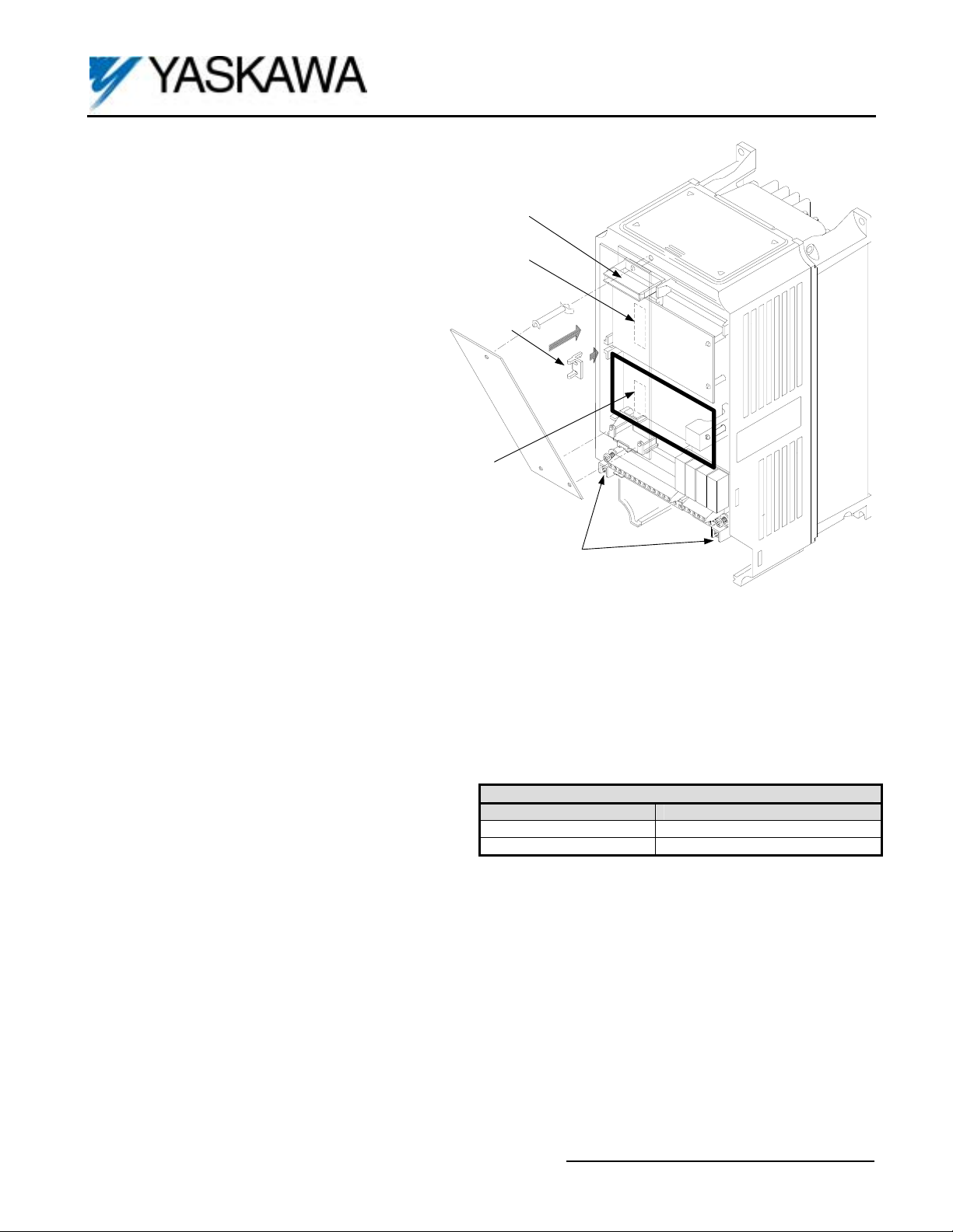
4CN
Option Card A
Introduction. The Digital Output option board is
mounted on the drive’s Control Board and allows the
user to employ isolated type digital signals to monitor
2CN
Option Card C
status outputs of the drive (alarm signal, zero-speed
detection, etc.)
Receiving. All equipment is tested against defect at
Option Clip
the factory. Report any damages or shortages evident
when the equipment is received to the commercial
carrier who transported the equipment.
Warning: Hazardous voltage can cause severe injury
or death. Lock all power sources feeding the drive in
the “OFF” position.
Caution: This option card uses CMOS IC chips. Use
3CN
Option Card D
proper electrostatic discharge (ESD) protective
procedures when handling the card to prevent I.C.
damage or erratic drive operation.
Important:
Grounding Terminal
1. If this option is being installed in a drive with
an encoder (PG) feedback option card, that
card will need to be temporarily removed to
allow access to connector 3CN on the drive’s
Figure 1. DO-08 Option Card installation
control board and TD1 – TD11 on the DO-08
option card.
2. Before installing this option, a technically qualified
individual, who is familiar with this type of
equipment and the hazards involved, should read
this entire installation guide.
Installation and Wiring:
1. Disconnect all electrical power to the drive.
2. Remove the drive’s front cover.
3. Check that the “CHARGE” indicator lamp inside the
drive is off.
4. Use a voltmeter to verify that the voltage at the
incoming power terminals (L1, L2, L3) has been
Output Type Quantity
Photocoupler Output 6 (common emitter)
Relay Contact Output 2 (independent)
Table 1. Specifications
disconnected.
5. Circuit Board Installation: See Figure 1.
a) Position the option card above the control board’s 3CN connector and gently press the card into place.
b) Connect the green ground wire to the grounding terminal on the main control board.
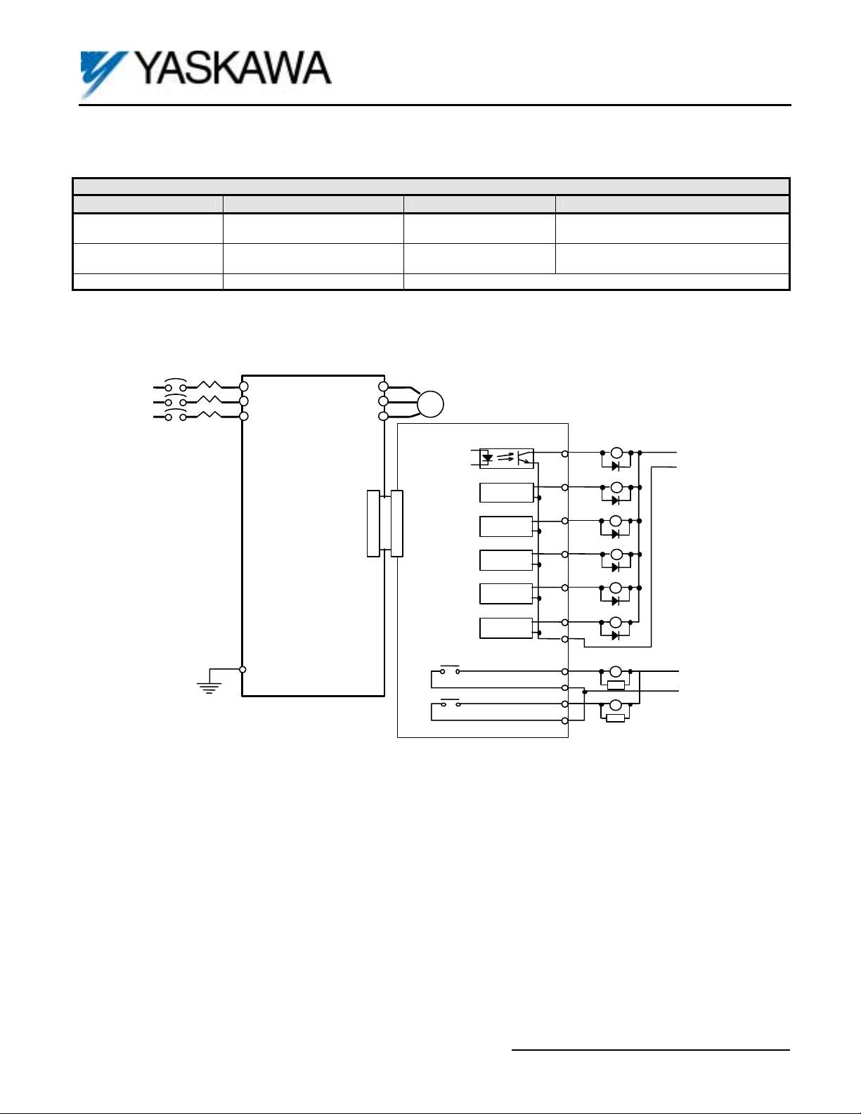
6. Wiring: Refer to Figure 2 and Table 2. Make wire connections between the DO-08 card and the drive, as well as all
peripheral devices. Observe the following:
a) Keep DO-08 (i.e. control circuit) wiring separate from main circuit input/output wiring. A separate metallic
grounded conduit with only the option card’s wiring running through it is preferred.
b) To prevent erroneous operation caused by noise interference, use shielded cable for control signal wiring, and
limit the distance to 50m (165 feet) or less.
c) Refer to the drive technical manual for additional information on the use of shielded cable.
7. Adjustment: There are no adjustments to be made on the Digital Output option card; however, drive parameters will
have to be reprogrammed for the desired output signal content. Refer to Table 3.
8. Reinstall and secure the drive’s front cover.
9. Place this instruction sheet with the drive’s technical manual.
Yaskawa Electric America, Inc. – www.drives.com
IG.AFD.56, Page 1 of 4
Date: 07/01/04, Rev: 04-07
Page 2
Digital Output Option Card
Terminal
(1)
TD1 - TD4
TD5 - TD10
6 outputs (common emitter)
TD11 Output Common, 0V
(1) Terminal Screw Size = M3
MCCB
Attention must be paid to the diode polarity.
*
Be sure to install a surge absorbing circuit.
**
Table 2. Terminal functions of Digital Output Card DO-08
Type Capacity Output Signal
Relay Contact:
2 outputs (independent)
Photocoupler:
250VAC, 1A or less
30VDC, 1A or less
48VDC, 50mA or less See Table 4
L1 (R)
L2 (S)
L3 (T)
F7, G7,
GPD515/G5,
G5HHP
E
T1 (U)
T2 (V)
T3 (W)
3CN 3CN
MOTOR
I M
DO-08
Card
RELAYS
PHOTOCOUPLER
K2
K1
TD5
TD6
TD7
TD8
TD9
TD10
TD11
TD1
TD2
TD3
TD4
Figure 2. DO-08 Interconnection Diagram
**
*
3RY
4RY
5RY
6RY
7RY
8RY
1RY
2RY
RC
RC
See Table 4
DO-08
+24VDC
0V
200VAC
Yaskawa Electric America, Inc. – www.drives.com
IG.AFD.56, Page 2 of 4
Date: 07/01/04, Rev: 04-07
Page 3
Digital Output Option Card
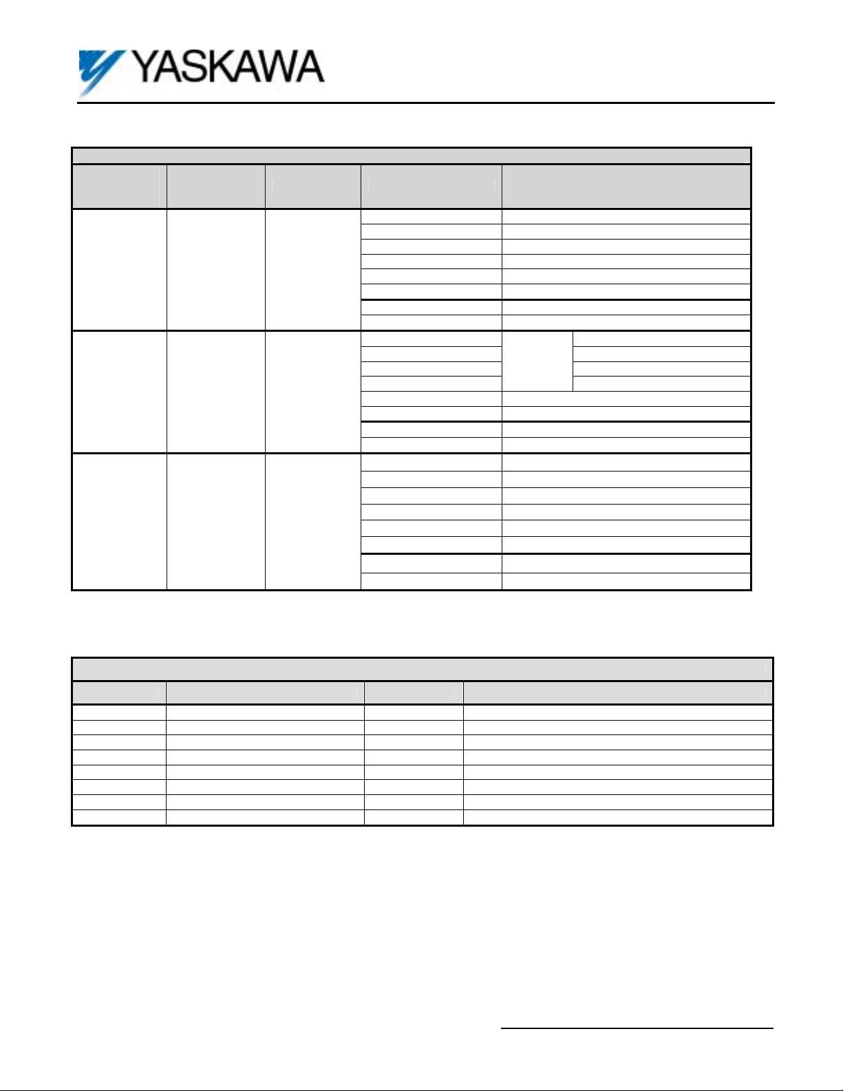
Table 3. DO-08 Output Mode Selection
GPD515/G5
Parameter
F6-01 Setting
0 0 Fixed Data
1 1 Coded Output
- 2
F7, G7
Parameter
F5-09 Setting
Output Type Terminal Output Content
Individually
Selectable
See Table 5
DO-08
TD5-TD11 Overcurrent (SC, OC, GF)
TD6-TD11 Overvoltage (OV)
TD7-TD11 Drive Overload (OL2)
TD8-TD11 DC Bus Fuse Blown (FU, PUF)
TD9-TD11 Not Used
TD10-TD11 Overheat (OH)
TD1-TD2 Zero-Speed
TD3-TD4 Speed Agree
TD5-TD11 Bit 0
TD6-TD11 Bit 1
TD7-TD11 Bit 2
TD8-TD11
TD9-TD11 Zero-Speed
TD10-TD11 Speed Agree
TD1-TD2 Running
TD3-TD4 Minor Fault
TD5-TD11 F5-01
TD6-TD11 F5-02
TD7-TD11 F5-03
TD8-TD11 F5-04
TD9-TD11 F5-05
TD10-TD11 F5-06
TD1-TD2 F5-07
TD3-TD4 F5-08
Coded
Output,
See
Table 4
Bit 3
Table 4. Details of DO-08 Coded Output
Bits 3, 2, 1, 0 Output Content Bits 3, 2, 1, 0 Output Content
0000 No Fault 1000 External Fault (EFXX)
0001 Overcurrent (SC, OC, GF) 1001 Drive Hardware Fault (CPFXX)
0010 Overvoltage (OV) 1010 Motor Overload (OL1)
0011 Drive Overload (OL2) 1011 Not Used
0100 Drive Overheat (OH2) 1100 Power Loss (UV) (Including momentary power loss)
0101 Not Used 1101 Not Used
0110 Fuse Blown (FU) 1110 Not Used
0111 Not Used 1111 Cooling Fan Fault (Fan)
Yaskawa Electric America, Inc. – www.drives.com
IG.AFD.56, Page 3 of 4
Date: 07/01/04, Rev: 04-07
Page 4

Digital Output Option Card
Table 5. DO-08 Output Selection (F7, G7 only and F5-09 = 2)
Control Mode (A1-02)
F5-01
to
F5-08
Setting
During Run 1
0
(ON: Run command with voltage output. Includes Decel and DC injection)
1 Zero Speed (ON: Fout < E1-09) X X X X X
2 Fref/Fout Agree 1 (ON: Fref = Fout, detection width L4-02) X X X X X
3 Fref/L4-01 Agree 1 (ON: Fref = Fout = ±L4-01, detection width L4-02) X X X X X
4
Frequency Detection 1 (ON: +L4-01 ≥ Fout ≥ - L4-01, detection width L4-02)
5
Frequency Detection 2 (ON: Fout ≥ +L4-01 or Fout ≤ -L4-01, detection width L4-02)
6 Inverter Ready (ON: No fault and not in programming mode) X X X X X
DC Bus Undervoltage (UV1, UV2)
7
(ON: DC bus below L2-05 or loss of pre-charge contactor answerback)
8 Baseblock 1 N.O. (ON: Baseblock function is active) X X X X X
9 Operator Reference (ON: Frequency reference source is from operator) X X X X X
A Local/Remote Operation (ON: Start/stop source is from operator) X X X X X
B Torque Detection 1 N.O. (ON: Current is greater/lower than L6-02 for L6-03 time) X X X X X
C Loss of Frequency Reference (Function enabled when L4-05 = 1) X X X X X
D Braking Resistor Fault (ON: Resistor overheat or braking transistor fault) X X X X X
E Fault (ON: Fault occurred other than CPF00 and CPF01) X X X X X
F Not Used (Set for use as remote I/O when drive has network communication link) X X X X X
10 Alarm (ON: Alarm occurring) X X X X X
11 Fault Reset Command Active (keypad, terminal, network) X X X X X
12 Timer Function Output (See parameter group B4) X X X X X
13 Fref/Fout Agree 2 (detection width L4-04) X X X X X
14 Fref/Fout Agree 2 (ON: Fref = Fout = L4-03, detection width L4-04) X X X X X
15
16
17 Torque Detection 1 N.C. (OFF: Current is greater/lower than L6-02 for L6-03 time) X X X X X
18 Torque Detection 2 N.O. (OFF: Current is greater/lower than L6-05 for L6-06 time) X X X X X
19 Torque Detection 2 N.C. (OFF: Current is greater/lower than L6-05 for L6-06 time) X X X X X
1A Reverse Direction (ON: Motor rotation is in reverse due to run command or Fref) X X X X X
1B Baseblock 2 N.C. (OFF: Baseblock function is active) X X X X X
1C
1D Regenerative operation (ON: During regenerative operation.) - - - X X
1E Automatic Fault Restart (ON: Automatic fault restart function is active. See L5-01) X X X X X
1F Motor Overload OL1 Alarm (ON: 90% or greater OL1 detection level) X X X X X
20 OH Alarm (ON: Heatsink temperature is greater than L8-02) X X X X X
30 Torque Limit (ON: Torque limit function active) - - X X X
31 Speed Limit During Speed Control (ON: Speed limit function active) - - - X X
32
33 Zero Servo Complete (ON: Zero servo function is within the b9-02 detection width) - - - X -
37
38
(1) Available in the G7 only.
(2) Not available in the GPD515/G5.
Frequency Detection 3 (ON: Fout ≤ L4-03, detection width L4-04)
Frequency Detection 4 (ON: Fout ≥ L4-03, detection width L4-04)
Motor 2 Selection
(ON: Motor 2 selected using a digital input (H1-XX) programmed for “16”)
(2)
Speed Limit During Torque Control (ON: Speed limit function active)
During Run 2 (ON: Run command with voltage output. Does not include baseblock,
DC injection, or initial excitation)
Drive Enable
(2)
(ON: Drive Enable selected using a digital input (H1-XX) programmed for “6A”)
Function
0: V/F
1: V/F PG
X X X X X
X X X X X
X X X X X
X X X X X
X X X X X
X X X X X
X X X X X
- - - X X
X X X X X
X X X X X
DO-08
2: OLV
3: FV
(1)
4: OLV2
Yaskawa Electric America, Inc. – www.drives.com
IG.AFD.56, Page 4 of 4
Date: 07/01/04, Rev: 04-07
 Loading...